legrand crt catalogue 040919 - systemcontrols.co.in
TRANSCRIPT

GREEN T.HE
HIGH EFFICIENCY CAST RESIN
TRANSFORMERS
THE GLOBAL SPECIALIST IN ELECTRICAL AND DIGITAL BUILDING INFRASTRUCTURES
2

L11egrand
Index
4-6 General Green T.HE cast resin transformers 4
featUres Advantages of Green T.HE transformers 6
Certified quality 8
9-13
Catalogue
Resin Green T.H E
9
pages 12 kV insulation class 10
17,5 kV insulation class 11
24 kV insulation class 12
36 kV insulation class 13
14-15
Technical Installation accessories
informations
14
I Gceoo T.HE I INDEX I '

2
GREENT.HE cast resin
Transformers
With the application in July 2015 of the European
Commission Regulation for ecodesign, efficiency
standards of transformers will be more strenght
The Green T.HE Transformers comply with the EN 50588-1 Standard. They are designed and manufactured according to the Regulation 548/2014 of European Commission and the new Ecodesign guidelines 2009/125/CE. Legrand Green T.HE Transformers, designed and manufactured in accordance with new Regulation, ensure a consistent reduction in energy consumption, resulting in economic savings and the decrease of CO emissions released into the atmosphere.
The EN 50588-1 Standard applies to 50 Hz, 5 kVA to 40 MVA three-phase dry-type distribution transformers with maximum voltage per component not exceeding 36 kV.
548/2014 Regulation sets out the requirements (mandatory) on ecodesign requirements for electric transformers with a minimum power rating of 1 kVA used in electricity transmission and distribution networks.
4
Green T.HE GENERAL FEATURES 5
WWW.PROFESSIONISTI.BTICINO.IT
STEP 1 (from 1 July 2015) STEP 2 (from 1 July 2021)
Rated power (kVA)
Maximum Maximum load losses no-load losses P
k (W) P
0 (W)
Maximum load losses P
k (W)
Maximum no-load losses P
0 (W)
≤ 50 BK
(1700) A0 (200) A
K (1500) A
0 – 10% (180)
100 BK
(2050) A0 (280) A
K (1800) A
0 – 10% (252)
160 B (2900) A (400) A (2600) A – 10% (360)
250 BK
(3800) A0 (520) A
K (3400) A
0 – 10% (468)
400 B (5500) A (750) A (4500) A – 10% (675)
630 BK
(7600) A0 (1100) A
K (7100) A
0 – 10% (990)
800 Ak (8000) A
0 (1300) A
k (8000) A
0 – 10% (1170)
1000 Ak (9000) A
0 (1550) A
k (9000) A
0 – 10% (1395)
1250 Ak (11000) A
0 (1800) A
k (11000) A
0 – 10% (1620)
1600 Ak (13000) A
0 (2200) A
k (13000) A
0 – 10% (1980)
2000 A (16000) A (2600) A (16000) A – 10% (2340)
2500 Ak (19000) A
0 (3100) A
k (19000) A
0 – 10% (2790)
3150 A (22000) A (3800) A (22000) A – 10% (3420)
NO-LOAD LOSSES (P )
LOAD LOSSES (P )
A
A
A B
0
k
k
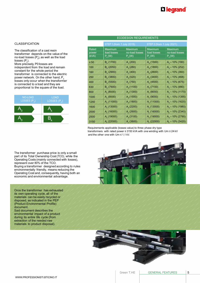
CLASSIFICATION
The classification of a cast resin transformer depends on the value of the no-load losses (P ), as well as the load
ECODESIGN REQUIREMENTS
losses (P ). More precisely, P0 losses are independent from the load and remain constant for the whole period the transformer is connected to the electric power network. On the other hand, P losses only occur when the transformer is connected to a load and they are proportional to the square of the load.
K 0 K 0
K 0 K 0
O K
0 k
k 0 k 0
0 k
k 0 k 0
Requirements applicable (losses value) to three phase dry type transformers with rated power ≤ 3150 kVA with one winding with Um ≤ 24 kV and the other one with Um ≤ 1,1 kV.
The transformer purchase price is only a small part of its Total Ownership Cost (TCO), while the Operating Costs (mainly connected with losses), represent over 80% of the TCO. Buying a transformer designed according to rules environmentally friendly, means reducing the Operating Cost and, consequently, having both an economic and environmental advantage.
Once the transformer has exhausted its own operating cycle, all of the materials can be easily recycled or disposed, as indicated in the PEP (Product Environmental Profile) document. Said document describes the environmental impact of a product during its entire life cycle (from extraction of the needed raw materials to product disposal).

6
ADVANTAGES OF
Green T.HE TRANSFORMERS
Low, partial
discharges, HIGH Quality
According to the product standard related to design of resin transformers (CEI EN 60076-11, i.e. IEC 60076-11), all the windings with a voltage ≥ 3.6kV should be subjected to the measurement of the partial discharges and the value measured should not exceed 10 picocoulombs (pC). Partial discharges are a microscopic phenomena occurring inside insulating resin cavities and can speed up ageing. For this reason, it is important that the values of such currents are limited.
A low value of partial discharges gives an indication of the positive factors, such as:
a solid design criteria has been applied a high quality of raw materials used a high precision during the conductor winding phases a high competence during the epoxy resin pouring around the high-voltage winding a high impregnation coefficient of low voltage coil a rigour in final assembling of semi-manufacturers
It is easy to see a coloration between a lower level of partial discharges that leads to a higher resistance to work stresses and consequently to a higher life expectance of the transformer under examination.
TYPE OF THE PARTIAL DISCHARGES Depending on the type, discharges can be divided into:
Corona effect: is the discharge that happen in air or in a gas surrounding a conductor, this usually occurs in relation to points and edges present on the conductors.
Surface discharges: it occurs on the surface of an insulator and which generally causes damage on the surface of the insulation itself, reducing the efficiency
Internal discharges: represents the main cause of life-cycle decrease of the insulating material)
Treeing (branched discharge channel): is the channel of pre- discharge which is formed following the degradation of the insulation and which leads to a destructive discharge.

Green T.HE GENERAL FEATURES 7
WWW.PROFESSIONISTI.BTICINO.IT
Reliability guaranteed
With Green T.HE series, Legrand provides customers a top-quality product which guarantees long-term excellent performance and reliability. When the Green T.HE transformers are subjected to partial discharges (according to CEI 60076-11, i.e. IEC 60076-11), values under 5 pC have been always been achieved (which exceeds the requirement of the standard which establishes the maximum value at 10 pC).
(*) standard features: all transformers according to the European Directive 548/2014 and with the code starting with “F”, such as FK4AAAGBA Green T.HE-eu AA KVA 1000 kV 20/0,4. All the transformer accessories shown on pages 14 and 15 of this catalogue are expressly excluded from the guarantee extension.

8
CERTIFIED QUALITY
Certifications The Legrand test lab “IB03” has recently received the qualification by ACAE to work according to the 17025 standard on all routine tests and on some tests for medium-voltage transformers.
Such acknowledgement and qualification is a very important plus obtained and Legrand with few others around the world can offer this to their customers.
Every cast resin transformer is tested before the delivery to the customer.
ACCEPTANCE TESTS
Measurement of winding resistance IEC 60076-11 (clause 15) Measurement of voltage ratio and check of phase displacement IEC 60076-11 (clause 16) Measurement of short-circuit impedance and load loss IEC 60076-11 (clause 17) Measurement of no-load loss and current IEC 60076-11 (clause 18) Separate-source AC withstand voltage test IEC 60076-11 (clause 19) Induced AC withstand voltage test IEC 60076-11 (clause 20) Partial discharge measurement IEC 60076-11 (clause 22) TYPE TESTS (on request)
Lightning impulse test IEC 60076-11 (clause 21) Temperature-rise test IEC 60076-11 (clause 23) SPECIAL TESTS (on request)
Measurement of sound level IEC 60076-11 (clause24) Short-circuit test IEC 60076-11 (clause 25)
Green T.HE CATALOGUE 9
C
M1
2
M1
2
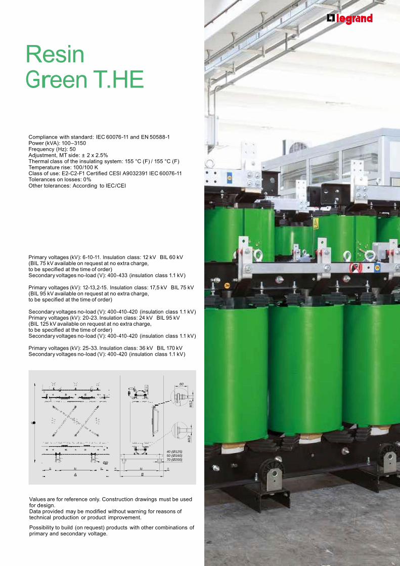
Resin Green T.HE
Compliance with standard: IEC 60076-11 and EN 50588-1 Power (kVA): 100 –3150 Frequency (Hz): 50 Adjustment, MT side: ± 2 x 2.5% Thermal class of the insulating system: 155 °C (F) / 155 °C (F) Temperature rise: 100/100 K Class of use: E2-C2-F1 Certified CESI A9032391 IEC 60076-11 Tolerances on losses: 0% Other tolerances: According to IEC/CEI
Primary voltages (kV): 6-10-11. Insulation class: 12 kV BIL 60 kV (BIL 75 kV available on request at no extra charge, to be specified at the time of order) Secondary voltages no-load (V): 400-433 (insulation class 1.1 kV)
Primary voltages (kV): 12-13,2-15. Insulation class: 17,5 kV BIL 75 kV (BIL 95 kV available on request at no extra charge, to be specified at the time of order)
Secondary voltages no-load (V): 400-410-420 (insulation class 1.1 kV) Primary voltages (kV): 20-23. Insulation class: 24 kV BIL 95 kV (BIL 125 kV available on request at no extra charge, to be specified at the time of order) Secondary voltages no-load (V): 400-410-420 (insulation class 1.1 kV)
Primary voltages (kV): 25-33. Insulation class: 36 kV BIL 170 kV Secondary voltages no-load (V): 400-420 (insulation class 1.1 kV)
60
ØR
= Ic = =
A
Ic
B
40 (Ø125) 50 (Ø160) 70 (Ø200)
=
Values are for reference only. Construction drawings must be used for design. Data provided may be modified without warning for reasons of technical production or product improvement.
Possibility to build (on request) products with other combinations of primary and secondary voltage.
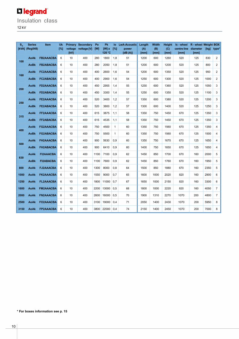
Insulation class 12 kV
10
S R
[kVA]
Series
(Reg548)
Item Uk
[%]
Primary
voltage
[kV]
Secondary
voltage [V]
Po
[W]
Pk
[W] a
120 °C
Io
[%]
LwA-Acoustic
power
[dB (A)]
Length
(A)
[mm]
Width
(B)
[mm]
Height
(C)
[mm]
Ic - wheel
centre line
[mm]
R - wheel
diameter
[mm]
Weight
[kg]
BOX
type*
100
AoAk FB2AAACBA 6 10 400 280 1800 1,8 51 1200 600 1260 520 125 830 2
AoBk FB2ABACBA 6 10 400 280 2050 1,8 51 1200 600 1200 520 125 800 2
160
AoAk FC2AAACBA 6 10 400 400 2600 1,6 54 1200 600 1350 520 125 950 2
AoBk FC2ABACBA 6 10 400 400 2900 1,6 54 1250 600 1300 520 125 1000 2
200
AoAk FD2AAACBA 6 10 400 450 2955 1,4 55 1250 600 1360 520 125 1050 3
AoBk FD2ABACBA 6 10 400 450 3300 1,4 55 1250 600 1350 520 125 1100 3
250
AoAk FE2AAACBA 6 10 400 520 3400 1,2 57 1350 600 1380 520 125 1200 3
AoBk FE2ABACBA 6 10 400 520 3800 1,2 57 1300 600 1400 520 125 1250 3
315
AoAk FF2AAACBA 6 10 400 615 3875 1,1 58 1350 750 1450 670 125 1350 3
AoBk FF2ABACBA 6 10 400 615 4535 1,1 58 1350 750 1450 670 125 1350 3
400
AoAk FG2AAACBA 6 10 400 750 4500 1 60 1350 750 1560 670 125 1350 4
AoBk FG2ABACBA 6 10 400 750 5500 1 60 1350 750 1560 670 125 1500 4
500
AoAk FH2AAACBA 6 10 400 900 5630 0,9 60 1350 750 1670 670 125 1650 4
AoBk FH2ABACBA 6 10 400 900 6410 0,9 60 1400 750 1650 670 125 1650 4
630
AoAk FI2AAACBA 6 10 400 1100 7100 0,9 62 1450 850 1700 670 160 2000 5
AoBk FI2ABACBA 6 10 400 1100 7600 0,9 62 1450 850 1760 670 160 1950 5
800 AoAk FJ2AAACBA 6 10 400 1300 8000 0,8 64 1500 850 1880 670 160 2350 5
1000 AoAk FK2AAACBA 6 10 400 1550 9000 0,7 65 1600 1000 2020 820 160 2900 6
1250 AoAk FL2AAACBA 6 10 400 1800 11000 0,7 67 1650 1000 2150 820 160 3300 6
1600 AoAk FM2AAACBA 6 10 400 2200 13000 0,5 68 1800 1000 2220 820 160 4050 7
2000 AoAk FN2AAACBA 6 10 400 2600 16000 0,5 70 1900 1310 2270 1070 200 4800 7
2500 AoAk FO2AAACBA 6 10 400 3100 19000 0,4 71 2050 1400 2430 1070 200 5950 8
3150 AoAk FP2AAACBA 6 10 400 3800 22000 0,4 74 2150 1400 2450 1070 200 7000 8
* For boxes information see p. 15
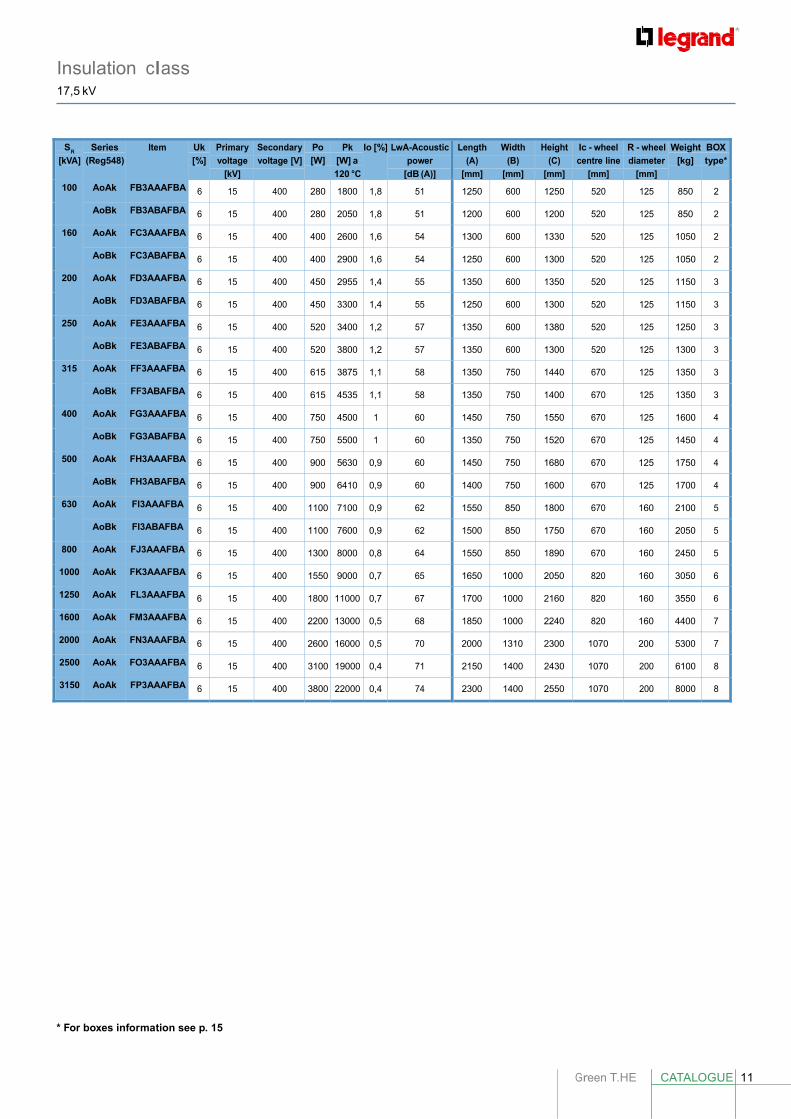
Insulation class 17,5 kV
Green T.HE CATALOGUE 11
S R
[kVA]
Series
(Reg548)
Item Uk
[%]
Primary
voltage
[kV]
Secondary
voltage [V]
Po
[W]
Pk
[W] a
120 °C
Io [%] LwA-Acoustic
power
[dB (A)]
Length
(A)
[mm]
Width
(B)
[mm]
Height
(C)
[mm]
Ic - wheel
centre line
[mm]
R - wheel
diameter
[mm]
Weight
[kg]
BOX
type*
100 AoAk FB3AAAFBA 6 15 400 280 1800 1,8 51 1250 600 1250 520 125 850 2
AoBk FB3ABAFBA 6 15 400 280 2050 1,8 51 1200 600 1200 520 125 850 2
160 AoAk FC3AAAFBA 6 15 400 400 2600 1,6 54 1300 600 1330 520 125 1050 2
AoBk FC3ABAFBA 6 15 400 400 2900 1,6 54 1250 600 1300 520 125 1050 2
200 AoAk FD3AAAFBA 6 15 400 450 2955 1,4 55 1350 600 1350 520 125 1150 3
AoBk FD3ABAFBA 6 15 400 450 3300 1,4 55 1250 600 1300 520 125 1150 3
250 AoAk FE3AAAFBA 6 15 400 520 3400 1,2 57 1350 600 1380 520 125 1250 3
AoBk FE3ABAFBA 6 15 400 520 3800 1,2 57 1350 600 1300 520 125 1300 3
315 AoAk FF3AAAFBA 6 15 400 615 3875 1,1 58 1350 750 1440 670 125 1350 3
AoBk FF3ABAFBA 6 15 400 615 4535 1,1 58 1350 750 1400 670 125 1350 3
400 AoAk FG3AAAFBA 6 15 400 750 4500 1 60 1450 750 1550 670 125 1600 4
AoBk FG3ABAFBA 6 15 400 750 5500 1 60 1350 750 1520 670 125 1450 4
500 AoAk FH3AAAFBA 6 15 400 900 5630 0,9 60 1450 750 1680 670 125 1750 4
AoBk FH3ABAFBA 6 15 400 900 6410 0,9 60 1400 750 1600 670 125 1700 4
630 AoAk FI3AAAFBA 6 15 400 1100 7100 0,9 62 1550 850 1800 670 160 2100 5
AoBk FI3ABAFBA 6 15 400 1100 7600 0,9 62 1500 850 1750 670 160 2050 5
800 AoAk FJ3AAAFBA 6 15 400 1300 8000 0,8 64 1550 850 1890 670 160 2450 5
1000 AoAk FK3AAAFBA 6 15 400 1550 9000 0,7 65 1650 1000 2050 820 160 3050 6
1250 AoAk FL3AAAFBA 6 15 400 1800 11000 0,7 67 1700 1000 2160 820 160 3550 6
1600 AoAk FM3AAAFBA 6 15 400 2200 13000 0,5 68 1850 1000 2240 820 160 4400 7
2000 AoAk FN3AAAFBA 6 15 400 2600 16000 0,5 70 2000 1310 2300 1070 200 5300 7
2500 AoAk FO3AAAFBA 6 15 400 3100 19000 0,4 71 2150 1400 2430 1070 200 6100 8
3150 AoAk FP3AAAFBA 6 15 400 3800 22000 0,4 74 2300 1400 2550 1070 200 8000 8
* For boxes information see p. 15

12
Insulation class 24 kV
S R
[kVA]
Series
(Reg548)
Item Uk
[%]
Primary
voltage
[kV]
Secondary
voltage [V]
Po
[W]
Pk
[W] a
120 °C
Io
[%]
LwA-Acoustic
power
[dB (A)]
Length
(A)
[mm]
Width
(B)
[mm]
Height
(C)
[mm]
Ic - wheel
centre line
[mm]
R - wheel
diameter
[mm]
Weight
[kg]
BOX
type*
100
AoAk FB4AAAGBA 6 20 400 280 1800 1,8 51 1250 600 1300 520 125 900 2
AoBk FB4ABAGBA 6 20 400 280 2050 1,8 51 1250 600 1250 520 125 900 2
160
AoAk FC4AAAGBA 6 20 400 400 2600 1,6 54 1250 600 1360 520 125 1050 2
AoBk FC4ABAGBA 6 20 400 400 2900 1,6 54 1250 600 1300 520 125 1050 2
200
AoAk FD4AAAGBA 6 20 400 450 2955 1,4 55 1350 600 1370 520 125 1200 3
AoBk FD4ABAGBA 6 20 400 450 3300 1,4 55 1350 600 1300 520 125 1200 3
250
AoAk FE4AAAGBA 6 20 400 520 3400 1,2 57 1350 600 1410 520 125 1350 3
AoBk FE4ABAGBA 6 20 400 520 3800 1,2 57 1350 600 1350 520 125 1350 3
315
AoAk FF4AAAGBA 6 20 400 615 3875 1,1 58 1350 750 1470 670 125 1450 3
AoBk FF4ABAGBA 6 20 400 615 4535 1,1 58 1350 750 1400 670 125 1450 3
400
AoAk FG4AAAGBA 6 20 400 750 4500 1 60 1450 750 1570 670 125 1700 4
AoBk FG4ABAGBA 6 20 400 750 5500 1 60 1450 750 1570 670 125 1600 4
500
AoAk FH4AAAGBA 6 20 400 900 5630 0,9 60 1450 750 1700 670 125 1800 4
AoBk FH4ABAGBA 6 20 400 900 6410 0,9 60 1450 750 1650 670 125 1800 4
630
AoAk FI4AAAGBA 6 20 400 1100 7100 0,9 62 1550 850 1820 670 160 2150 5
AoBk FI4ABAGBA 6 20 400 1100 7600 0,9 62 1550 850 1820 670 160 2150 5
800 AoAk FJ4AAAGBA 6 20 400 1300 8000 0,8 64 1550 850 1920 670 160 2550 5
1000 AoAk FK4AAAGBA 6 20 400 1550 9000 0,7 65 1650 1000 2090 820 160 3150 6
1250 AoAk FL4AAAGBA 6 20 400 1800 11000 0,7 67 1750 1000 2180 820 160 3650 6
1600 AoAk FM4AAAGBA 6 20 400 2200 13000 0,5 68 1900 1000 2260 820 160 4600 7
2000 AoAk FN4AAAGBA 6 20 400 2600 16000 0,5 70 2000 1310 2320 1070 200 5550 7
2500 AoAk FO4AAAGBA 6 20 400 3100 19000 0,4 71 2150 1310 2450 1070 200 6300 8
3150 AoAk FP4AAAGBA 6 20 400 3800 22000 0,4 74 2300 1400 2560 1070 200 8100 8
* For boxes information see p. 15
Green T.HE CATALOGUE 13
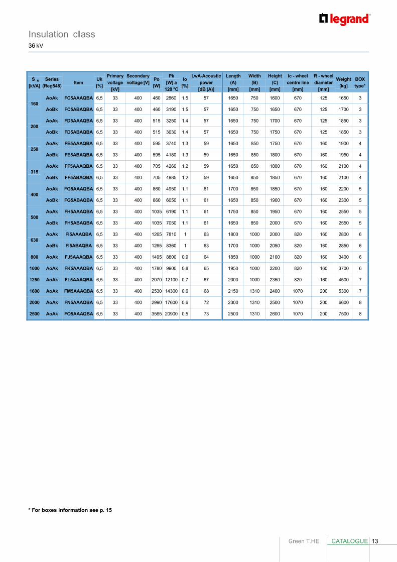
Insulation class 36 kV
S
[kVA]
Series
(Reg548)
Item
Uk
[%]
Primary
voltage
[kV]
Secondary
voltage [V]
Po
[W]
Pk
[W] a
120 °C
Io
[%]
LwA-Acoustic
power
[dB (A)]
Length
(A)
[mm]
Width
(B)
[mm]
Height
(C)
[mm]
Ic - wheel
centre line
[mm]
R - wheel
diameter
[mm]
Weight
[kg]
BOX
type*
160
AoAk FC5AAAQBA 6,5 33 400 460 2860 1,5 57 1650 750 1600 670 125 1650 3
AoBk FC5ABAQBA 6,5 33 400 460 3190 1,5 57 1650 750 1650 670 125 1700 3
200
AoAk FD5AAAQBA 6,5 33 400 515 3250 1,4 57 1650 750 1700 670 125 1850 3
AoBk FD5ABAQBA 6,5 33 400 515 3630 1,4 57 1650 750 1750 670 125 1850 3
250
AoAk FE5AAAQBA 6,5 33 400 595 3740 1,3 59 1650 850 1750 670 160 1900 4
AoBk FE5ABAQBA 6,5 33 400 595 4180 1,3 59 1650 850 1800 670 160 1950 4
315
AoAk FF5AAAQBA 6,5 33 400 705 4260 1,2 59 1650 850 1800 670 160 2100 4
AoBk FF5ABAQBA 6,5 33 400 705 4985 1,2 59 1650 850 1850 670 160 2100 4
400
AoAk FG5AAAQBA 6,5 33 400 860 4950 1,1 61 1700 850 1850 670 160 2200 5
AoBk FG5ABAQBA 6,5 33 400 860 6050 1,1 61 1650 850 1900 670 160 2300 5
500
AoAk FH5AAAQBA 6,5 33 400 1035 6190 1,1 61 1750 850 1950 670 160 2550 5
AoBk FH5ABAQBA 6,5 33 400 1035 7050 1,1 61 1650 850 2000 670 160 2550 5
630
AoAk FI5AAAQBA 6,5 33 400 1265 7810 1 63 1800 1000 2000 820 160 2800 6
AoBk FI5ABAQBA 6,5 33 400 1265 8360 1 63 1700 1000 2050 820 160 2850 6
800 AoAk FJ5AAAQBA 6,5 33 400 1495 8800 0,9 64 1850 1000 2100 820 160 3400 6
1000 AoAk FK5AAAQBA 6,5 33 400 1780 9900 0,8 65 1950 1000 2200 820 160 3700 6
1250 AoAk FL5AAAQBA 6,5 33 400 2070 12100 0,7 67 2000 1000 2350 820 160 4500 7
1600 AoAk FM5AAAQBA 6,5 33 400 2530 14300 0,6 68 2150 1310 2400 1070 200 5300 7
2000 AoAk FN5AAAQBA 6,5 33 400 2990 17600 0,6 72 2300 1310 2500 1070 200 6600 8
2500 AoAk FO5AAAQBA 6,5 33 400 3565 20900 0,5 73 2500 1310 2600 1070 200 7500 8
R
* For boxes information see p. 15

14
Green T.HE cast resin transformersInstallation accessories
200073 200074 200137
200138
CB0012
CB0240
CB0272
Type
Cat. Nos. Ventilation bars
The ventilation busbars temporarily increase the rated power (under normal service conditions). According to standard IEC 60076-1, a transformer is called AN even if it is equipped with discontinuous ventilation. If a transformer with AF continuous service is requested, it is not possible to refer to the codes included in this catalogue, but the transformer will be designed according to the customer’s needs.
Range (kVA) ∆Power (%) Notes
CB02444 100 - 250 + 40 CB02454 315 - 800 + 40
A temporary increase
Cat. Nos. Surge arrester kit
Vn (kV)
130075D 6 130054D 10-11 130055D 15 130056D 20
Rubber supports (anti vibration)
Range (kVA) Description
170019 ≤1600 4 buffers supplied for mounting under the transformer casters
CB02464 1000 - 1250 + 40 CB01414 1600 - 2500 + 30 CB01412 3150 + 20
in rated conditions 170020 ≥2000 4 buffers supplied for mounting under the transformer casters
Cupal plates
Temperature measurement probes
Probes are supplied mounted on to the transformer and wired to aluminium IP 66 junction box.
Range (kVA) N° ∆t (°C) Installation
Cupal is a bimetal sheet made up of one copper sheet and one aluminium sheet inseparably welded together through a special mechanical procedure.
Range (kVA) Description
030014 * ≤ 160 40 x 40 CUPAL plate Pt100 ≤2000 3 - on the LV (3) windings Pt100 ≥2500 3 - on the LV (3) windings Pt100 ≤2000 3+1 - on the LV (3) windings
+ on the core (1)
030008 * ≥ 200 and ≤ 315
030009 * ≥ 400 and ≤ 630
50 x 50 CUPAL plate 60 x 60 CUPAL plate
Pt100 ≥2500 3+1 - on the LV (3) windings + on the core (1)
PTC - 3+3 130-140 on the LV (3 pairs) windings for alarm and release.
PTC - 3+3 110-120 on the LV (3 pairs) windings for alarm and release.
030010 * 800 80 x 80 CUPAL plate 030011 * 1000 100 x 100 CUPAL plate 030012 * ≥ 1250 120 x 120 CUPAL plate
Note: * the codes refer to a single CUPAL plate
Example: - Power = 1250 kVA corresponds to the CUPAL plate code item 030012
PTC - 3+3+3 110-130 -140
Temperature control devices
on the LV (3 pairs) windings for fan control, for alarm and release.
- Quantity calculation: 2 plates x 4 BT terminals = 8 CUPAL plates
Central units are supplied unassembled Type Description
220035 VRT200 fan control 220002 T154 temperature control for 4 Pt100 probes 220023 MT200L temperature control for 4 Pt100 probes 220010 T119 DIN temperature control for 6 PTC probes,
preset for DIN rail mounting 220004 T 119 temperature control for 6 PTC probes 220174 AT100 fan control 220197 NT935 temperature control for 4 Pt100 probe
with analogue and digital output
Green T.HE CATALOGUE 15
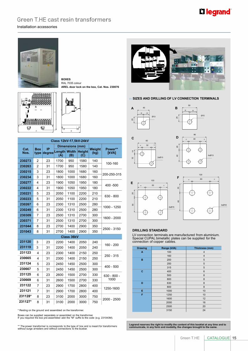
Green T.HE cast resin transformersInstallation accessories
Drawing Range (kVA) Thickness (mm)
A 100 4
160 4
B 200 5
250 5
315 5
C 400 6
500 8
800 8
D 630 8
800 8
E 1000 10
F 1250 10
1600 12
2000 16
2500 20
3150 24
231120 3 23 2200 1400 2050 240 160 - 200
231119 3 31 2200 1400 2050 240
231123 4 23 2300 1400 2150 250 250 - 315
230665 4 31 2300 1400 2150 250
231124 5 23 2450 1450 2500 300 400 - 500
230667 5 31 2450 1450 2500 300
231125 6 23 2600 1500 2700 330 630 - 800 - 1000 230669 6 31 2600 1500 2700 330
231122 7 23 2900 1700 2800 400 1250-1600
231121 7 31 2900 1700 2800 400
231128* 8 23 3100 2000 3000 750 2000 - 2500
231127* 8 31 3100 2000 3000 750
C
32
14
20
50
25
40
20
25
60
30
D
BOXES RAL 7035 colour
AREL door lock on the box, Cat. Nos. 230076
n SIZES AND DRILLING OF LV CONNECTION TERMINALS
A 40
= =
50
B = =
Ø13 Ø15
Cat.
A
Box
B
Class 12kV-17,5kV-24kV
Dimensions (mm) IP
Weight
Power**
C
60
= 32 =
80
= 40 =
Nos. type degree Length Width Height (kg) [kVA] (A) (B) (C)
2xØ13 4xØ13
230273 2 23 1700 950 1580 140
230263 2 31 1700 950 1580 140
230215 3 23 1800 1000 1680 160
230234 3 31 1800 1000 1680 160
230277 4 23 1900 1050 1950 180
230222 4 31 1900 1050 1950 180
230221 5 23 2050 1100 2200 210
230223 5 31 2050 1100 2200 210
230267 6 23 2300 1310 2500 280
230249 6 31 2300 1310 2500 280
230309 7 23 2500 1310 2700 300
230371 7 31 2500 1310 2700 300
231044 8 23 2700 1400 2900 350
100-160
200-250-315
E 400 -500 =
630 - 800
1000 - 1250
1600 - 2000
100 50
F
=
4xØ15
120
= 60 =
4xØ18
231043 8 31 2700 1400 2900 350
Class 36kV
2500 - 3150 DRILLING STANDARD LV connection terminals are manufactured from aluminium. Special CUPAL bimetallic plates can be supplied for the connection of copper cables.
* Resting on the ground and assembled on the transformer.
Boxes can be supplied separately or assembled on the transformer. If you required the box pre-assembled add the “M” suffix to the code (e.g. 231043M).
** The power transformer is corresponds to the type of box and is meant for transformers without surge arresters and without connections to the busbar.
Legrand reserves the right to modify the content of this booklet at any time and to communicate, in any form and modality, the changes brought to the same.

AD
-EX
TR
16H
EC
/GB
- M
arc
h 2
01
6
FOLLOW US ALSO ON
www.legrand.com
www.youtube.com/legrand
twitter.com/@legrand
Head office and International Department 87045 Limoges Cedex - France Tel.: + 33 (0) 5 55 06 87 87 Fax: + 33 (0) 5 55 06 74 55