leica icon robot 50 - survey instrument sales€¦ · introduction icon robot 50 2 introduction...
TRANSCRIPT

Leica iCON robot 50User Manual
Version 1.0English

2iCON robot 50Introduction
IntroductionPurchase Congratulations on the purchase of a iCON robot 50 series instrument.
This manual contains important safety directions as well as instructions for setting up the product and operating it. Refer to "6 Safety Directions" for further informa-tion.Read carefully through the User Manual before you switch on the product.
To ensure safety when using the system, please also observe the directions and instructions contained in the User Manual and Safety Handbook issued by the:• Machine manufacturer,• Controller manufacturer and• Sensor manufacturer.
Productidentification
The type and the serial number of your product are indicated on the type plate.Enter the type and serial number in your manual and always refer to this information when you need to contact your agency or Leica Geosystems authorised service work-shop.
Type: _______________Serial No.: _______________

Introduction iCON robot 50 3
Symbols The symbols used in this manual have the following meanings:
Trademarks • Windows and Windows CE are a registered trademark of Microsoft Corporation• CompactFlash and CF are trademarks of SanDisk Corporation• Bluetooth is a registered trademark of Bluetooth SIG, IncAll other trademarks are the property of their respective owners.
Validity of this manual
This manual applies to all iCON robot 50 Series instruments. Where there are differ-ences between the various models they are clearly described.
Type Description
�Danger Indicates an imminently hazardous situation which, if not avoided, will result in death or serious injury.
�Warning Indicates a potentially hazardous situation or an unintended use which, if not avoided, could result in death or serious injury.
�Caution Indicates a potentially hazardous situation or an unintended use which, if not avoided, may result in minor or moderate injury and/or appreciable material, financial and environmental damage.
Important paragraphs which must be adhered to in practice as they enable the product to be used in a technically correct and efficient manner.

4iCON robot 50Introduction
Availabledocumentation
Refer to the following resources for all iCON robot 50 documentation and software• the Leica iCon DVD• http://myworld.leica-geosystems.com/
It is recommended to set-up the product while reading through this manual.
Name Description and Format
User Manual All instructions required in order to operate the product to a basic level are contained in the User Manual. Provides an overview of the product together with technical data and safety directions.
Name Description and Format
System Soft-ware Manual
Overall comprehensive guide to the product and program functions. Included are detailed descriptions of special software/hardware settings and soft-ware/hardware functions.

Table of Contents iCON robot 50 5
Table of ContentsIn this manual Chapter Page
1 Description of the System 10
1.1 System Components 101.2 System Concept 14
1.2.1 Software Concept 141.2.2 Data Storage 151.2.3 Power Concept 16
1.3 Container Contents 171.4 Instrument Components 21
2 User Interface 24
2.1 Control Panel 242.2 Operating Principles 272.3 Ports 29

6iCON robot 50Table of Contents
3 Operation 30
3.1 Instrument Setup 303.2 Autodetect Behaviour 333.3 Instrument Setup for Remote Control 34
3.3.1 Remote Control Setup 343.3.2 LED Indicators on CommunicationHandle 36
3.4 Battery 383.4.1 Operating Principles 383.4.2 Instrument Battery 41
3.5 Working with the CompactFlash Card 433.6 Guidelines for Correct Results 45
4 Check & Adjust 48
4.1 Overview 484.2 Preparation 514.3 Combined Adjustment (l, t, i, c and ATR) 534.4 Adjusting the Circular Level of the Instrument and Tribrach 544.5 Adjusting the Circular Level of the Prism Pole 564.6 Inspecting the Laser Plummet of the Instrument 574.7 Servicing the Tripod 59

Table of Contents iCON robot 50 7
5 Care and Transport 60
5.1 Transport 605.2 Storage 615.3 Cleaning and Drying 625.4 Maintenance 63
6 Safety Directions 64
6.1 General Introduction 646.2 Intended Use 656.3 Limits of Use 676.4 Responsibilities 686.5 Hazards of Use 70
6.5.1 Safety hazards related to the product 706.6 Laser Classification 79
6.6.1 General 796.6.2 Distancer, Measurements with Reflectors (IR mode) 806.6.3 Distancer, Measurements without Reflectors (RL mode) 826.6.4 Automatic Target Recognition ATR 866.6.5 PowerSearch PS 886.6.6 Electronic Guide Light EGL 906.6.7 Laser Plummet 91
6.7 Electromagnetic Compatibility EMC 946.8 FCC Statement, Applicable in U.S. 976.9 ICES-003 Statement, Applicable in Canada 101

8iCON robot 50Table of Contents
7 Technical Data 102
7.1 Angle Measurement 1027.2 Distance Measurement with Reflectors (IR mode) 1037.3 Distance Measurement without Reflectors (RL mode) 1057.4 Automatic Target Recognition ATR 1077.5 PowerSearch PS 1107.6 Conformity to National Regulations 111
7.6.1 ConstructionRobot 1117.6.2 Communication side cover with Bluetooth 1127.6.3 CommunicationHandle 113
7.7 General Technical Data 1157.7.1 iCON robot 50 Technical Data 115
7.8 Scale Correction 1227.9 Reduction Formulas 128
8 International Limited Warranty, Software License Agreement 132
9 End User Licence Agreement EULA 134
Index 138

Table of Contents iCON robot 50 9

10iCON robot 50Description of the System
1 Description of the System1.1 System Components
Main components
Component Description
iCON robot 50 • an instrument for measuring, calculating and capturing data.• comprised of various models with a range of accuracy classes.• combined with a multi-purpose controller to conduct remote
control surveys.
CC50 or CC60 Multi-purpose controller enabling the remote control of iCON robot 50 via short range Bluetooth and WiFi.
TRACK_001
iCON robot C50
CC60CC61
CC50
CCD3
CO
M

Description of the System iCON robot 50 11
Terminology The following terms and abbreviations may be found in this manual:
CC61 or CCD3 with CC50
Multi-purpose controller enabling the remote control of iCON robot 50 via long range Bluetooth and WiFi.
LM office An office software consisting of a suite of standard and extended programs for the viewing, exchange and management of data.
Component Description
Term Description
ATR Automatic Target Recognition
ATR refers to the instrument sensor which enables the automatic fine pointing to a prism.
Automated Instruments fitted with ATR are referred to as Automated.
Three automation modes are available with ATR:• None: no ATR - no automation and no tracking.• ATR: automatic fine pointing to a prism.• LOCK: automatic tracking of an already targeted prism.

12iCON robot 50Description of the System
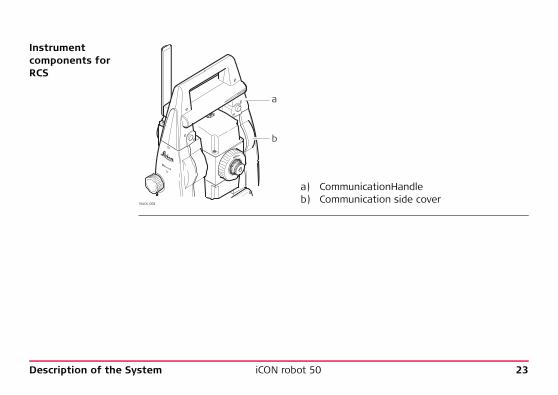
Communication-Handle
CommunicationHandle is a component of the Remote Control System (RCS). It is both, an integrated communication module with attached antenna and a handle to carry the instrument. Available models are: WiFi, long range Bluetooth and radio handle.
Communication side cover
Communication side cover has integrated short range Bluetooth. In combination with CommunicationHandle it is a component of RCS.
EDM Electronic Distance Measurement
EDM refers to the laser distancer incorporated into the instru-ment which enables distance measurement.
Two measuring modes are available:• IR mode. This mode refers to the ability to measure distances
to prisms.• RL mode. This mode refers to the ability to measure
distances without prisms.
Term Description

Description of the System iCON robot 50 13
EGL Electronic Guide Light
An EGL fitted to an instrument assists with prism targeting. It consists of two differently coloured flashing lights located in the instrument telescope housing. The person holding the prism can align him/herself into the instrument’s line of sight.
Motorised Instruments fitted with internal motors, enabling automatic hori-zontal and vertical turning are referred to as Motorised.
PinPoint PinPoint refers to the Reflectorless EDM technology which enables measuring to any surface with a visible red laser spot.
PowerSearch PowerSearch refers to the instrument sensor which enables the automatic rapid finding of a prism.
Term Description

14iCON robot 50Description of the System
1.2 System Concept1.2.1 Software Concept
Software type
Software upload All instrument software is stored in the System RAM of the instrument. The software can be uploaded onto the instrument using the following method:• By connecting the CompactFlash card directly to the computer either via an
internal card slot housing or an external OMNI drive, the software is transferred to the card, which is then stored to the System RAM.
Software type Description
System software This software comprises the central functions of the instrument. It is also referred to as firmware.
Application program
It is recommended to control the instrument with Leica Geosystems field software. Other 3rd party software prod-ucts may also be available.Refer to the respective software manual for more information.

Description of the System iCON robot 50 15
1.2.2 Data Storage
Memory device
Unplugging connecting cables or removing the CompactFlash card during the meas-urement may cause loss of data. Always ensure the instrument is OFF before removing the CompactFlash card or removing cables.
CompactFlash card: A CompactFlash card housing is standard. A CompactFlash card can be inserted and removed. Various storing capacities are available.
Whilst other CompactFlash cards may be used, Leica recommends Leica CompactFlash cards and cannot be held responsible for data loss or any other error that may occur when using a non-Leica card.

16iCON robot 50Description of the System
1.2.3 Power Concept
General Use only the Leica Geosystems batteries, chargers and accessories or accessories recommended by Leica Geosystems to ensure the correct functionality of the instru-ment.
Power options InstrumentPower for the instrument can be supplied either internally or externally. An external battery is connected to the instrument using a LEMO cable.Internal battery: One GEB221 battery fitted into the battery compartment.External battery: One GEB171 battery connected via cable.
Description of the System iCON robot 50 17
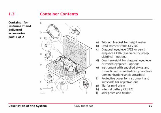
1.3 Container Contents
Container for instrument and deliveredaccessoriespart 1 of 2
a) Tribrach bracket for height meterb) Data transfer cable GEV102c) Diagonal eyepiece GFZ3 or zenith
eyepiece GOK6 (eyepiece for steep sighting) - optional
d) Counterweight for diagonal eyepiece or zenith eyepiece - optional
e) Instrument with supplied stylus and tribrach (with standard carry handle or CommunicationHandle attached)
f) Protective cover for instrument and sunshade for objective lens
g) Tip for mini prismh) Internal battery GEB221i) Mini prism and holder
c
b
a
d
f
gi
e
hTRACK_002

18iCON robot 50Description of the System
Container for instrument and deliveredaccessoriespart 2 of 2
a) Pocket knife - optionalb) Spare stylusc) User manuald) 2 x CompactFlash cards and coverse) Tool set for circular level and EDM
adjustments - comprising two adjusting pins, two allen keys and one screwdriver
f) Battery chargerg) Car adapter power plug for battery
charger (stored under battery charger)
d
c
a
b
gTRACK_003
f
e

Description of the System iCON robot 50 19
Container for CC60/CC61
a) MPR 122 360° Prism or GRZ4 360° Prism
b) Manualsc) GRZ101 360° Mini Prismd) USB-drivee) CC60/CC61f) Cable-Setg) Battery for CC60/CC61h) Stylusi) AC-AdapterROBO_001
a
b
g
f
h
i
c
d
e

20iCON robot 50Description of the System
Container for CC50
a) Battery CC50b) Manualsc) GRZ101 360° Mini Prismd) USB-drivee) CC50f) MPR 122 360° Prism or
GRZ4 360° Prism g) Cable-Seth) Stylusi) AC-AdapterROBO_002
a
b
g
f
h
i
c
d
e

Description of the System iCON robot 50 21
1.4 Instrument Components
Instrumentcomponentspart 1 of 2
a) Carry handleb) Optical sightc) Telescope, integrating EDM, ATR, EGL, PSd) EGL flashing diode - yellowe) EGL flashing diode - redf) PowerSearchg) Coaxial optics for angle and distance meas-
urement, and exit port of visible laser beam for distance measurements
h) CompactFlash card compartmenti) Horizontal drivej) Tribrach securing screwk) Label "leveling hint"
a b c de f g
h i j kTRACK_006

22iCON robot 50Description of the System
Instrumentcomponentspart 2 of 2
l) Vertical drivem) Focusing ringn) Battery compartmento) Circular levelp) Tribrach footscrewq) Interchangeable eyepiecer) Control PanelTRACK_007
l m
n qo p r
TR
K CO
MP
WR
Description of the System iCON robot 50 23
Instrumentcomponents for RCS
a) CommunicationHandleb) Communication side cover
TRACK_008
a
b

24iCON robot 50User Interface
2 User Interface2.1 Control Panel
Control Panel
a) TRK Tracking LEDb) COM Communication LEDc) PWR Power LEDd) ON/OFF button
TRK
COM
PWRa b c dTRACK_009

User Interface iCON robot 50 25
Description of LED indicators
IF the is THEN
PWR off power is off.
green power is okay, battery status is okay.
flashing green power is low. The remaining time for which enough power is available depends on the temperature and the age of the battery.
red power is very low. The battery should be changed.
COM green Bluetooth is in data mode and ready for connection.
blue Bluetooth has connected.
red Internal Bluetooth is off, communication on Port 2 is active to communicate with field software over a handle.
off Internal Bluetooth is off, Port 1 serial is active for communication with field software.
flashing red Firmware upload failed.

26iCON robot 50User Interface
TRK off no prism found.
red instrument is in startup mode and not ready.
flashing green prism locked but not tracking.
green prism locked and tracking.
flashing red uploading firmware.
IF the is THEN

User Interface iCON robot 50 27
2.2 Operating Principles
Turn instrument on 1. Press and hold ON/OFF for 2 s.2. Release when PWR LED turns green. When the red TRK LED switches off the
instrument is ready.
Turn instrument off
1. Press and hold ON/OFF for 2 s. PWR LED turns red.2. Release and instrument shuts down.
Using the instrument with internal Bluetooth
1. Press and hold ON/OFF for 5 s.2. Release when the COM LED turns green. All LEDs turn to their current status.3. Internal Bluetooth is now enabled for use with a controller.
Using the instrument with cable
1. Press and hold ON/OFF for 10 s. BT LED switches off and Bluetooth is disabled.2. Release and all LEDs turn to their current status.3. RS232 mode (Port1) is now enabled for use with a controller.
Using the instrument with Communication-Handle and field software (geocom)
1. Press and hold ON/OFF for 15 s.2. Release when the COM LED turns red. All LEDs turn to their current status.3. CommunicationHandle (Port2) is now enabled for use with a controller (geocom).

28iCON robot 50User Interface
Reset instrument 1. Press and hold ON/OFF for 20 s.2. Release when PWR and TRK LEDs turn red and COM LED turns green.3. Instrument shuts down. All LEDs turn red.4. Instrument turns on again.5. LEDs turn to their current status.
When resetting the instrument following tasks will be performed:• The current job will be deleted.• System RAM will be formatted.• Factory default settings will be activated.• Cable mode will be activated (Baudrate 115200).

User Interface iCON robot 50 29
2.3 Ports
Available ports Port Location
Port 1 This port is located at the base of the instrument and is always available.
Port 2 (Handle) This port is located on top of Communication side cover.
Port 3 (BT) This port is housed within Communication side cover.
30iCON robot 50Operation
3 Operation3.1 Instrument Setup
Description This topic describes an instrument setup over a marked ground point using the laser plummet. It is always possible to set up the instrument without the need for a marked ground point.
Important features:• It is always recommended to shield the instrument from direct sunlight and avoid
uneven temperatures around the instrument.• The laser plummet described in this topic is built into the vertical axis of the
instrument. It projects a red spot onto the ground, making it appreciably easier to centre the instrument.
• The laser plummet cannot be used in conjunction with a tribrach equipped with an optical plummet.

Operation iCON robot 50 31
Setup step-by-step
Step Description
Shield the instrument from direct sunlight and avoid uneven temperatures around the instrument.
1. Extend the tripod legs to allow for a comfortable working posture. Position the tripod over the marked ground point, centring it as well as possible.
2. Fasten the tribrach and instrument onto the tripod.
TRACK_010
2
5 4
5
51
3
1
1
TRK
COMPWR TR
KCOM
PWR
1
26
6
7
7

32iCON robot 50Operation
3. Turn on the instrument by pressing ON/OFF for 2 s. Activate the laser plummet. Refer to GeoPad/Site Foreman manual to access level & laser plummet dialog.
4. Move the tripod legs (1) and use the tribrach footscrews (6) to centre the plummet (4) over the ground point.
5. Adjust the tripod legs to level the circular level (7).
6. By using the electronic level turn the tribrach footscrews (6) to precisely level the instrument.
7. Centre the instrument precisely over the ground point (4) by shifting the tribrach on the tripod plate (2).
8. Repeat steps 6. and 7. until the required accuracy is achieved.
Step Description

Operation iCON robot 50 33
3.2 Autodetect Behaviour
Description • The instrument incorporates an autodetect behaviour and automatically detects the following devices:• CommunicationHandle• radios/modems
• Whenever a device is attached, the instrument responds with two short beeps.• Whenever a device is removed, the instrument responds with one long beep.
Radio/Modemin clip-on housing
• All radios and modems that are built into a clip-on housing are automatically detected by the instrument when attached to clip-on housing, but the device settings are not automatically set.
Communication-Handle
• CommunicationHandle is automatically detected by the instrument when it is attached.
• WiFi and long range Bluetooth Handles appear as "C1" or "C2" identification while they are searched for pairing. Example reading: "iCR52 280536 C1"• CCD1 = WiFi shown as "C1"• CCD2 = Bluetooth shown as "C2"

34iCON robot 50Operation
3.3 Instrument Setup for Remote Control3.3.1 Remote Control Setup
Setup step-by-step
Step Description
Refer to "3.1 Instrument Setup" for the initial instrument setup onto a tripod. To remove the instrument carry handle: Press and hold the four unlock push buttons and lift off the handle.
2
2
2
3
4
1
TRACK_014

Operation iCON robot 50 35
1. To install the CommunicationHandle, first make sure that the interface connection on the underside of the handle is on the same side as the Communication side cover. Then press and hold the four unlock push buttons and attach the handle.
• Ensure that there is a tight fit with the instrument after releasing the push buttons. If no connection can be found, re-check that handle is seated firmly.
2. Swing the CommunicationHandle antenna into an upright position.
Refer to field software manual for more information.
Step Description

36iCON robot 50Operation
3.3.2 LED Indicators on CommunicationHandle
LED Indicators DescriptionThe CommunicationHandle has Light Emitting Diode indicators. They indicate the basic CommunicationHandle status.Diagram of the LED Indicators
a) Power LEDb) Link LEDc) Data Transfer LEDd) Mode LEDTRACK_015
a b c d

Operation iCON robot 50 37
Description of the LED Indicators
IF the is THEN
Power LED off power is off.
green power is on.
Link LED off no connection link to remote controller.
red radio link to remote controller.
Data Transfer LED off no data transfer to/from remote controller.
green orgreen flashing
data transfer to/from remote controller.
Mode LED off data mode.
red configuration mode.
38iCON robot 50Operation
3.4 Battery3.4.1 Operating Principles
Charging/first-time use
For charging and first-time use, the following must be obtained:
• The battery must be charged prior to using for the first time because it is deliv-ered with an energy content as low as possible.
• For new batteries or batteries that have been stored for a long time (> three months), it is effectual to make only one charge/discharge cycle.
• For Li-Ion batteries, a single discharging and charging cycle is sufficient. We recommend carrying out the process when the battery capacity indicated on the charger or on a Leica Geosystems product deviates significantly form the actual battery capacity available.
• The permissible temperature range for charging is between 0°C to +40°C/+32°F to +104°F. For optimal charging we recommend charging the batteries at a low ambient temperature of +10°C to +20°C/+50°F to +68°F if possible.
• It is normal for the battery to become warm during charging. Using the chargers recommended by Leica Geosystems, it is not possible to charge the battery if the temperature is too high.

Operation iCON robot 50 39
Operation/Discharging
• The batteries can be operated from -20°C to +55°C/-4°F to +131°F.• Low operating temperatures reduce the capacity that can be drawn; very high
operating temperatures reduce the service life of the battery.
�Warning If charged or discharged, batteries not recommended by Leica Geosystems may be damaged. They may burn and explode.Precautions:Only charge and discharge batteries recommended by Leica Geosystems.
Operation of indoor-use products (Charger and AC-Adapter)
The following refers to operation of indoor-use products e.g. Charger and AC-Adapter:
�Danger The product is not designed for use under wet and severe conditions. If unit becomes wet it may cause you to receive an electric shock.Precautions:Use the product only in dry environments, for example in buildings or vehicles. Protect the product against humidity. If the product becomes humid, it must not be used!
40iCON robot 50Operation
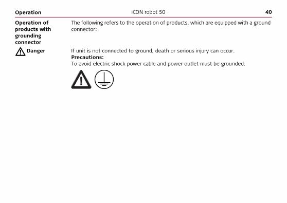
Operation of products with grounding connector
The following refers to the operation of products, which are equipped with a ground connector:
�Danger If unit is not connected to ground, death or serious injury can occur.Precautions:To avoid electric shock power cable and power outlet must be grounded.

Operation iCON robot 50 41
3.4.2 Instrument Battery
Inserting and removing the Battery step-by-step
Step Description
1. Face the instrument so that the vertical drive screw is on the left. The battery compartment is now on the left side of the instrument. Turn the knob to the vertical position, opening the lid of the battery compartment.
2. Pull out the battery housing.
3. Pull the battery from the battery housing.
4. A pictogram of the battery is displayed inside the battery housing. This is a visual aid to assist in placing the battery correctly.
TR
KC
OM
PW
R
TRACK_016
2
1
73
5
4

42iCON robot 50Operation
5. Place the battery into the battery housing, ensuring that the contacts are facing outward. Click the battery into position.
6. Place the battery housing into the battery compartment. Push the battery housing in until it fits completely into the battery compartment.
7. Turn the knob to lock the battery compartment. Ensure that the knob is returned to its original horizontal position.
Step Description

Operation iCON robot 50 43
3.5 Working with the CompactFlash Card
• Keep the card dry.• Use it only within the specified temperature range.• Do not bend the card.• Protect the card from direct impacts.
Failure to follow these instructions could result in data loss and/or permanent damage to the card.
Insert and remove a CompactFlash card step-by-step
TRACK_017
1
7
26 4
5 3
44iCON robot 50Operation
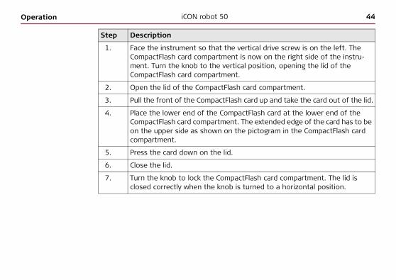
Step Description
1. Face the instrument so that the vertical drive screw is on the left. The CompactFlash card compartment is now on the right side of the instru-ment. Turn the knob to the vertical position, opening the lid of the CompactFlash card compartment.
2. Open the lid of the CompactFlash card compartment.
3. Pull the front of the CompactFlash card up and take the card out of the lid.
4. Place the lower end of the CompactFlash card at the lower end of the CompactFlash card compartment. The extended edge of the card has to be on the upper side as shown on the pictogram in the CompactFlash card compartment.
5. Press the card down on the lid.
6. Close the lid.
7. Turn the knob to lock the CompactFlash card compartment. The lid is closed correctly when the knob is turned to a horizontal position.

Operation iCON robot 50 45
3.6 Guidelines for Correct Results
Very short distances may be measured reflectorless in IR mode to well reflecting targets. Note that the distances are corrected with the additive constant defined for the active reflector.
Distance measurement
When measurements are being made using the red laser EDM, the results may be influ-enced by objects passing between the EDM and the intended target surface. This occurs because reflectorless measurements are made to the first surface returning sufficient energy to allow the measurement to take place. For example, if the intended target surface is the surface of a road, but a vehicle passes between the EDM and the target surface as a measurement is triggered, the measurement may be made to the side of the vehicle. The result is the distance to the vehicle, not to the road surface.
TRACK_064
46iCON robot 50Operation
Accurate measurements to prisms should not be made in reflectorless mode.
When a distance measurement is triggered, the EDM measures to the object which is in the beam path at that moment. If a temporary obstruction, for example a passing vehicle, heavy rain, fog or snow is between the instrument and the point to be meas-ured, the EDM may measure to the obstruction.
Do not measure with two instruments to the same target simultaneously to avoid getting mixed return signals.
ATR/lock Instruments equipped with an ATR sensor permit automatic angle and distance meas-urements to prisms. The prism is sighted with the optical sight. After initiating a distance measurement, the instrument sights the prism centre automatically. Vertical and horizontal angles and the distance are measured to the centre of the prism. The lock mode enables the instrument to follow a moving prism.
As with all other instrument errors, the collimation error of the automatic target recognition must be redetermined periodically. Refer to the GeoPad/Site Foreman manual about checking and adjusting instruments.
If the prism location is changed too quickly, the target may be lost. Make sure that the speed does not exceed the figure given in the technical data.
�Warning Due to laser safety regulations and measuring accuracy, using the Long Range Reflec-torless EDM is only allowed to prisms that are more than 1000 m (3300 ft) away.

Operation iCON robot 50 47

48iCON robot 50Check & Adjust
4 Check & Adjust4.1 Overview
Description Leica instruments are manufactured, assembled and adjusted to the best possible quality. Quick temperature changes, shock or stress can cause deviations and decrease the instrument accuracy.It is therefore recommended to check and adjust the instrument from time to time. This can be done in the field by running through specific measurement procedures. The procedures are guided and have to be followed carefully and precisely as described in the following chapters. Some other instrument errors and mechanical parts can be adjusted mechanically.
Electronicadjustment
The following instrument errors can be checked and adjusted electronically:
Every angle measured in the daily work is corrected automatically if the compensator and the Hz-corrections are activated in the instrument configuration.
l, t Compensator longitudinal and transversal index errorsi Vertical index error, related to the standing axisc Hz collimation error, also called line of sight errora Tilting axis errorATR ATR zero point error for Hz and V - option

Check & Adjust iCON robot 50 49
Mechanicaladjustment
The following instrument parts can be adjusted mechanically:• Circular level on instrument and tribrach• Laser plummet• Optical plummet - option on tribrach• Allen screws on tripod
Precisemeasurements
To get precise measurements in the daily work, it is important:• To check and adjust the instrument from time to time.• To take high precision measurements during the check and adjust procedures.• To measure targets in two faces. Some of the instrument errors are eliminated
by averaging the angles from both faces.• Refer to "4.2 Preparation" to find more important points.
During the manufacturing process, the instrument errors are carefully determined and set to zero. As mentioned above, these errors can change and it is highly recom-mended to redetermine them in the following situations:• Before the first use• Before every high precision survey• After rough or long transportations• After long working periods• After long storage periods• If the temperature difference between current environment and the temperature
at the last calibration is more than 20°C

50iCON robot 50Check & Adjust
Summary of errors to be adjustedelectronically
Instrument error Effects Hz
Effects V
Elimination with two face measurement
Automatically corrected with proper adjust-ment
c - Line of sight error ---
a - Tilting axis error ---
l - Compensator index error ---
t - Compensator index error ---
i - V-Index error ---
ATR Collimation error ---

Check & Adjust iCON robot 50 51
4.2 Preparation
Before starting to work, the instrument has to become acclimatised to the ambient temperature. Approximately two minutes per °C of temperature difference from storage to working environment but at least 15 min should be taken into account.
Before determining the instrument errors, the instrument has to be levelled-up using the electronic level. Please refer to the Controller manual in order to use the electronic level.The tribrach, the tripod and the underground should be very stable and secure from vibrations or other disturbances.
The instrument should be protected from direct sunlight in order to avoid thermal warming.It is also recommended to avoid strong heat shimmer and air turbulence. The best conditions are usually early in the morning or with overcast sky.

52iCON robot 50Check & Adjust
Note, that even after good adjustment of the ATR, the crosshairs might not be posi-tioned exactly on the centre of the prism after an ATR measurement has been executed. This is a normal effect. To speed up the ATR measurement, the telescope is normally not positioned exactly on the centre of the prism. The small rest devia-tions, the ATR offsets are measured individually for each measurement and corrected electronically. This means that the Hz- and V- angles are corrected twice: first by the determined ATR errors for Hz and V and then by the individual small deviations of the current pointing.

Check & Adjust iCON robot 50 53
4.3 Combined Adjustment (l, t, i, c and ATR)
Description The combined adjustment procedure determines the following instrument errors in one process:
Refer to GeoPad/Site Foreman manual to gain further informations regarding all adjustment procedure.
l, t Compensator longitudinal and transversal index errorsi Vertical index error, related to the standing axisc Hz collimation error, also called line of sight errorATR Hz ATR zero point error for Hz angle - optionATR V ATR zero point error for V angle - option

54iCON robot 50Check & Adjust
4.4 Adjusting the Circular Level of the Instrument and Tribrach
Adjusting the circular levelstep-by-step
Step Description
1. Place and secure the instrument into the tribrach and onto a tripod.
2. Using the tribrach footscrews, level the instrument with the electronic level.
3. Check the position of the circular level on the instrument and tribrach.
TRACK_018
2
1 4TRK
COMPWR

Check & Adjust iCON robot 50 55
4. a) If both circular levels are centered, no adjustments are necessary
b) If one or both circular levels are not centered, adjust as follows:
Instrument: If it extends beyond the circle, use the supplied allen key to centre it with the adjustment screws. Turn the instrument by 200 gon (180°). Repeat the adjustment procedure if the circular level does not stay centered.
Tribrach: If it extends beyond the circle, use the supplied allen key to centre it with the adjustment screws.
After the adjustments, all adjusting screws should have the same tight-ening tension and no adjusting screw shall be loose.
Step Description
56iCON robot 50Check & Adjust
4.5 Adjusting the Circular Level of the Prism Pole
Adjusting the circular levelstep-by-step
Step Description
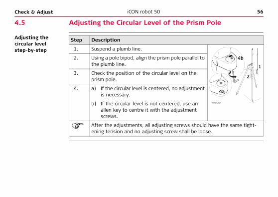
1. Suspend a plumb line.
2. Using a pole bipod, align the prism pole parallel to the plumb line.
3. Check the position of the circular level on the prism pole.
4. a) If the circular level is centered, no adjustment is necessary.
b) If the circular level is not centered, use an allen key to centre it with the adjustment screws.
After the adjustments, all adjusting screws should have the same tight-ening tension and no adjusting screw shall be loose.
TRACK_019
1
2
4b
4a

Check & Adjust iCON robot 50 57
4.6 Inspecting the Laser Plummet of the Instrument
The laser plummet is located in the vertical axis of the instrument. Under normal conditions of use, the laser plummet does not need adjusting. If an adjustment is necessary due to external influences, the instrument has to be returned to any Leica Geosystems authorised service workshop.
Inspecting the laser plummet step-by-step
The following table explains the most common settings.
3
2
4
5
360°
3 mm / 1.5 m
Ø 2.5 mm / 1.5 m
TRACK_021
TRK
COMPWR
1TR
KCOM
PWR

58iCON robot 50Check & Adjust
Step Description
1. Place and secure the instrument into the tribrach and onto a tripod.
2. Using the tribrach footscrews, level the instrument with the electronic level. Refer to GeoPad/Site Foreman manual to access electronic level.
3. Switch on the laser plummet. Refer to GeoPad/Site Foreman manual to access laser plummet. Inspection of the laser plummet should be carried out on a bright, smooth and horizontal surface, like a sheet of paper.
4. Mark the centre of the red dot on the ground.
5. Turn the instrument through 360° slowly, carefully observing the move-ment of the red laser dot.
The maximum diameter of the circular movement described by the centre of the laser point should not exceed 3 mm at a distance of 1.5 m.
6. If the centre of the laser dot describes a perceptible circular movement or moves more than 3 mm away from the point which was first marked, an adjustment may be required. Inform your nearest Leica Geosystems authorised service workshop. Depending on brightness and surface, the diameter of the laser dot can vary. At 1.5 m it is about 2.5 mm.

Check & Adjust iCON robot 50 59
4.7 Servicing the Tripod
Servicing the tripod step-by-step
The following table explains the most common settings.
Step Description
The connections between metal and timber components must always be firm and tight.
1. Tighten the leg cap screws moderately, with the supplied allen key.
2. Tighten the articulated joints on the tripod head just enough to keep the tripod legs open when lifting the tripod off the ground.
3. Tighten the allen screws of the tripod legs.
TRACK_022
12
3

60iCON robot 50Care and Transport
5 Care and Transport5.1 Transport
Transport in the field
When transporting the equipment in the field, always make sure that you• either carry the product in its original transport container,• or carry the tripod with its legs splayed across your shoulder, keeping the
attached product upright.
Transport in a road vehicle
Never carry the product loose in a road vehicle, as it can be affected by shock and vibration. Always carry the product in its transport container and secure it.
Shipping When transporting the product by rail, air or sea, always use the complete original Leica Geosystems packaging, transport container and cardboard box, or its equiva-lent, to protect against shock and vibration.
Shipping, transport of batteries
When transporting or shipping batteries, the person in charge of the product must ensure that the applicable national and international rules and regulations are observed. Before transportation or shipping, contact your local passenger or freight transport company.
Field adjustment After transport inspect the field adjustment parameters given in this user manual before using the product.

Care and Transport iCON robot 50 61
5.2 Storage
Product Respect the temperature limits when storing the equipment, particularly in summer if the equipment is inside a vehicle. Refer to "7 Technical Data" for information about temperature limits.
Field adjustment After long periods of storage inspect the field adjustment parameters given in this user manual before using the product.
Li-Ion batteries • Refer to "7.7 General Technical Data" for information about storage temperature range.
• A storage temperature range of -20°C to +30°C/-4°F to +86°F in a dry environ-ment is recommended to minimise self-discharging of the battery.
• At the recommended storage temperature range, batteries containing a 10% to 50% charge can be stored for up to one year. After this storage period the batteries must be recharged.
• Remove batteries from the product and the charger before storing.• After storage recharge batteries before using.• Protect batteries from damp and wetness. Wet or damp batteries must be dried
before storing or use.

62iCON robot 50Care and Transport
5.3 Cleaning and Drying
Objective, eyepiece and prisms
• Blow dust off lenses and prisms.• Never touch the glass with your fingers.• Use only a clean, soft, lint-free cloth for cleaning. If necessary, moisten the cloth
with water or pure alcohol. Do not use other liquids; these may attack the polymer components.
Fogging of prisms Reflector prisms that are cooler than the ambient temperature tend to fog. It is not enough simply to wipe them. Keep them for some time inside your jacket or in the vehicle to allow them to adjust to the ambient temperature.
Damp products Dry the product, the transport container, the foam inserts and the accessories at a temperature not greater than 40°C / 104°F and clean them. Do not repack until everything is completely dry. Always close the transport container when using in the field.

Care and Transport iCON robot 50 63
Charger and AC-adapter
Use only dry, clean, soft and lint-free cloths for cleaning.
Cables and plugs Keep plugs clean and dry. Blow away any dirt lodged in the plugs of the connecting cables.
5.4 Maintenance
Motorisation Maintenance of the motorisation in motorised products must be done in a Leica Geosystems authorised service workshop.Following conditions:• After about 4000 hours operation.• Twice a year in case of permanent use of the product.

64iCON robot 50Safety Directions
6 Safety Directions6.1 General Introduction
Description The following directions should enable the person responsible for the product, and the person who actually uses the equipment, to anticipate and avoid operational hazards.
The person responsible for the product must ensure that all users understand these directions and adhere to them.

Safety Directions iCON robot 50 65
6.2 Intended Use
Permitted use • Measuring horizontal and vertical angles.• Measuring distances.• Recording measurements.• Automatic target search, recognition and -tracking.• Visualizing the aiming direction and vertical axis.• Remote control of product.• Data communication with external appliances.• Computing with software.
Adverse use • Use of the product without instruction.• Use outside of the intended limits.• Disabling safety systems.• Removal of hazard notices.• Opening the product using tools, for example screwdriver, unless this is specifi-
cally permitted for certain functions.• Modification or conversion of the product.• Use after misappropriation.• Use of products with obviously recognizable damages or defects.• Use with accessories from other manufacturers without the prior explicit
approval of Leica Geosystems.

66iCON robot 50Safety Directions
• Aiming directly into the sun.• Inadequate safeguards at the working site, for example when measuring on
roads.• Deliberate dazzling of third parties.• Controlling of machines, moving objects or similar monitoring application without
additional control- and safety installations.
�Warning Adverse use can lead to injury, malfunction and damage.It is the task of the person responsible for the equipment to inform the user about hazards and how to counteract them. The product is not to be operated until the user has been instructed on how to work with it.
�Warning Unauthorised modification of building and constructions machines by mounting or installing the product may alter the function and safety of the machine.Precautions:Follow the instructions of the machine manufacturer. If no appropriate instruction is available, ask machine manufacturer for instructions before mounting or installing the product.

Safety Directions iCON robot 50 67
6.3 Limits of Use
Environment Suitable for use in an atmosphere appropriate for permanent human habitation: not suitable for use in aggressive or explosive environments.
�Danger Local safety authorities and safety experts must be contacted before working in hazardous areas, or in close proximity to electrical installations or similar situations by the person in charge of the product.
For Charger and AC-adapters
Suitable for use in dry environments only and not under adverse conditions.

68iCON robot 50Safety Directions
6.4 Responsibilities
Manufacturer of the product
Leica Geosystems AG, CH-9435 Heerbrugg, hereinafter referred to as Leica Geosystems, is responsible for supplying the product, including the user manual and original acces-sories, in a completely safe condition.
Manufacturers of nonLeica Geosystems accessories
The manufacturers of non Leica Geosystems accessories for the product are respon-sible for developing, implementing and communicating safety concepts for their products, and are also responsible for the effectiveness of those safety concepts in combination with the Leica Geosystems product.
Person in charge of the product
The person in charge of the product has the following duties:• To understand the safety instructions on the product and the instructions in the
user manual.• To be familiar with local regulations relating to safety and accident prevention.• To inform Leica Geosystems immediately if the product and the application
becomes unsafe.• To ensure that the national laws, regulations and conditions for the operation of
radio transmitters are respected.
�Warning The person responsible for the product must ensure that it is used in accordance with the instructions. This person is also accountable for the training and the deployment of personnel who use the product and for the safety of the equipment in use.

Safety Directions iCON robot 50 69
�Warning This procuct may be installed on building and construction machinery only by an appropriately trained and qualified specialist.

70iCON robot 50Safety Directions
6.5 Hazards of Use6.5.1 Safety hazards related to the product
�Warning The absence of instruction, or the inadequate imparting of instruction, can lead to incorrect or adverse use, and can give rise to accidents with far-reaching human, material, financial and environmental consequences.Precautions:All users must follow the safety directions given by the manufacturer and the direc-tions of the person responsible for the product.
�Caution Watch out for erroneous measurement results if the product has been dropped or has been misused, modified, stored for long periods or transported.Precautions:Periodically carry out test measurements and perform the field adjustments indicated in the user manual, particularly after the product has been subjected to abnormal use and before and after important measurements.

Safety Directions iCON robot 50 71
�Danger Because of the risk of electrocution, it is very dangerous to use poles, masts and extensions in the vicinity of electrical installations such as power cables or electrical railways.Precautions:Keep at a safe distance from electrical installations. If it is essential to work in this environment, first contact the safety authorities responsible for the electrical instal-lations and follow their instructions.
�Caution With the remote control of products, it is possible that extraneous targets will be picked out and measured.Precautions:When measuring in remote control mode, always check your results for plausibility.
�Warning If the product is used with accessories, for example masts, staffs, poles, you may increase the risk of being struck by lightning.Precautions:Do not use the product in a thunderstorm.

72iCON robot 50Safety Directions
�Caution Be careful when pointing the product towards the sun, because the telescope func-tions as a magnifying glass and can injure your eyes and/or cause damage inside the product.Precautions:Do not point the product directly at the sun.
�Warning During dynamic applications, for example stakeout procedures there is a danger of accidents occurring if the user does not pay attention to the environmental condi-tions around, for example obstacles, excavations or traffic.Precautions:The person responsible for the product must make all users fully aware of the existing dangers.
�Warning Inadequate securing of the working site can lead to dangerous situations, for example in traffic, on building sites, and at industrial installations.Precautions:Always ensure that the working site is adequately secured. Adhere to the regulations governing safety and accident prevention and road traffic.
�Warning Only Leica Geosystems authorised service workshops are entitled to repair these products.

Safety Directions iCON robot 50 73
�Warning If computers intended for use indoors are used in the field there is a danger of elec-tric shock.Precautions:Adhere to the instructions given by the computer manufacturer with regard to field use in conjunction with Leica Geosystems products.
�Caution If the accessories used with the product are not properly secured and the product is subjected to mechanical shock, for example blows or falling, the product may be damaged or people may sustain injury.Precautions:When setting-up the product, make sure that the accessories are correctly adapted, fitted, secured, and locked in position.Avoid subjecting the product to mechanical stress.
�Caution During the transport, shipping or disposal of batteries it is possible for inappropriate mechanical influences to constitute a fire hazard.Precautions:Before shipping the product or disposing of it, discharge the batteries by running the product until they are flat.When transporting or shipping batteries, the person in charge of the product must ensure that the applicable national and international rules and regulations are observed. Before transportation or shipping contact your local passenger or freight transport company.

74iCON robot 50Safety Directions
�Warning If charged or discharged, batteries not recommended by Leica Geosystems may be damaged. They may burn and explode.Precautions:Only charge and discharge batteries recommended by Leica Geosystems.
�Warning Using a battery charger not recommended by Leica Geosystems can destroy the batteries. This can cause fire or explosions.Precautions:Only use chargers recommended by Leica Geosystems to charge the batteries.
�Warning High mechanical stress, high ambient temperatures or immersion into fluids can cause leakage, fire or explosions of the batteries.Precautions:Protect the batteries from mechanical influences and high ambient temperatures. Do not drop or immerse batteries into fluids.
�Warning If battery terminals come in contact with jewellery, keys, metallised paper or other metals, short circuited battery terminals can overheat and cause injury or fire, for example by storing or transporting in pockets.Precautions:Make sure that the battery terminals do not come into contact with metallic objects.

Safety Directions iCON robot 50 75
�Caution During the operation of the product there is a hazard of squeezing extremities or entanglement of hairs and/or clothes by moving parts.Precautions:Keep a safe distance of the moving parts.
�Caution Installing near mechanically moving machine components may damage the product.Precautions:Deflect the mechanically moving machine components as far as possible and define a safe installation zone.
�Caution Beware of inadequate steering if machine is defective like after a crash or other damaging events or alterations to the machine.Precautions:Periodically perform control measurements and field adjustments on the machine as specified in the User Manual. While working, construction and grading should be checked by appropriate means, for example spirit level, tachymeter, before and after important measuring tasks.

76iCON robot 50Safety Directions
�Warning While steering or navigating the machine accidents can occur due:• the operator not paying attention to the surroundings (persons, ditches,
traffic, etc.), or• malfunctions of a system component, interference etc.
Precautions:The operator assures that the machine is operated, guided and monitored by a qual-ified user (e.g. driver). The user hast to be able to take emergency measures, for example an emergency stop.
For theAC-Adapters
The following must be obtained for handling of AC-Adapters:
�Warning If you open the product, either of the following actions may cause you to receive an electric shock:
• touching live components, or• using the product after incorrect attempts were made to carry out repairs.
Precautions:Do not open the product. Only Leica Geosystems authorised service workshops are entitled to repair these products.

Safety Directions iCON robot 50 77
Units equipped with a ground connector
The following refers to units, which are equipped with a ground connector:
�Danger If unit is not connected to ground, death or serious injury can occur.Precautions:To avoid electric shock power cable and power outlet must be grounded.
For the AC-Adapters and Chargers
The following must be obtained for handling with AC-Adapters and Chargers:
�Danger The product is not designed for use under wet and severe conditions. If unit becomes wet it may cause you to receive an electric shock.Precautions:Use the product only in dry environments, for example in buildings or vehicles. Protect the product against humidity. If the product becomes humid, it must not be used!

78iCON robot 50Safety Directions
�Warning If the product is improperly disposed of, the following can happen:• If polymer parts are burnt, poisonous gases are produced which may impair
health.• If batteries are damaged or are heated strongly, they can explode and cause
poisoning, burning, corrosion or environmental contamination.• By disposing of the product irresponsibly you may enable unauthorised persons
to use it in contravention of the regulations, exposing themselves and third parties to the risk of severe injury and rendering the environment liable to contamination.
• Improper disposal of silicone oil may cause environmental contamination.Precautions:
Product specific treatment and waste management information can be downloaded from the Leica Geosystems home page at http://www.leica-geosystems.com/treatment or received from your Leica Geosystems dealer.
The product must not be disposed with household waste.Dispose of the product appropriately in accordance with the national regulations in force in your country.Always prevent access to the product by unauthorised personnel.

Safety Directions iCON robot 50 79
6.6 Laser Classification6.6.1 General
General The following directions (in accordance with the state of the art - international standard IEC 60825-1 (2007-03) and IEC TR 60825-14 (2004-02)) provide instruc-tion and training information to the person responsible for the product and the person who actually uses the equipment, to anticipate and avoid operational hazards.
The person responsible for the product must ensure that all users understand these directions and adhere to them.
Products classified as laser class 1, class 2 and class 3R do not require:• laser safety officer involvement,• protective clothes and eyewear,• special warning signs in the laser working areaif used and operated as defined in this user manual due to the low eye hazard level.
Products classified as laser class 2 or class 3R may cause dazzle, flash-blindness and afterimages, particularly under low ambient light conditions.

80iCON robot 50Safety Directions
6.6.2 Distancer, Measurements with Reflectors (IR mode)
General The EDM module built into this product produces a visible laser beam which emerges from the telescope objective.
The laser product described in this section is classified as laser class 1 in accordance with:• IEC 60825-1 (2007-03): "Safety of laser products"• EN 60825-1 (2007-10): "Safety of laser products"
These products are safe under reasonably foreseeable conditions of operation and are not harmful to the eyes provided that the products are used and maintained in accordance with this user manual.
Description Value
Maximum average radiant power 0.33 mW
Pulse duration 800 ps
Pulse repetition frequency 100 MHz - 150 MHz
Wavelength 650 nm - 690 nm

Safety Directions iCON robot 50 81
Labelling
a) Laser beam
TRACK_023
a
Type: iCR.... Art.No.: ......
Equipo.No.: ......Power: 12V / 7,4V ---, 1A maxLeica Geosystems AGCH-9435 HeerbruggManufactured: ....Made in Switzerland S.No.: ......Complies with 21 CFR 1040.10 and 1040.11 except for deviations pursuant to Laser Notice No.50, dated July 26, 2001.This device complies with part 15 of the FCC Rules. Operation is subject to the following two conditions: (1) This device may not cause harmful interference,and (2) this device must accept any interference received, including interference that may cause undesired operation.
Class 1 Laser Productaccording to
IEC 60825-1 ( 2007 - 03 )

82iCON robot 50Safety Directions
6.6.3 Distancer, Measurements without Reflectors (RL mode)
General The EDM module built into the product produces a visible laser beam which emerges from the telescope objective.
The laser product described in this section, is classified as laser class 3R in accord-ance with:• IEC 60825-1 (2007-03): "Safety of laser products"• EN 60825-1 (2007-10): "Safety of laser products"
Direct intrabeam viewing may be hazardous (low-level eye hazard), in particular for deliberate ocular exposure. The risk of injury for laser class 3R products is limited because of: a) unintentional exposure would rarely reflect worst case conditions of (e.g.) beam
alignment with the pupil, worst case accommodation,b) inherent safety margin in the maximum permissible exposure to laser radiation
(MPE),c) natural aversion behaviour for exposure to bright light for the case of visible radi-
ation.

Safety Directions iCON robot 50 83
�Warning From a safety perspective class 3R laser products should be treated as potentially hazardous.Precautions:Prevent direct eye exposure to the beam. Do not direct the beam at other people.
�Warning Potential hazards are not only related to direct beams but also to reflected beams aimed at reflecting surfaces such as prisms, windows, mirrors, metallic surfaces etc.Precautions:Do not aim at areas that are essentially reflective, such as a mirror, or which could emit unwanted reflections.Do not look through or beside the optical sight at prisms or reflecting objects when the laser is switched on, in laser pointer or distance measurement mode. Aiming at prisms is only permitted when looking through the telescope.
Description ValueMaximum average radiant power 5.00 mWPulse duration 800 psPulse repetition frequency 100 MHz - 150 MHzWavelength 650 nm - 690 nmBeam divergence 0.2 mrad x 0.3 mradNOHD (Nominal Ocular Hazard Distance) @ 0.25s 80 m / 262 ft

84iCON robot 50Safety Directions
Labelling
a) Laser beam
a
TRACK_065
Laser Aperture
Laser RadiationAvoid direct eye exposure
Class 3R Laser Productaccording to
IEC 60825-1 ( 2007-03 )Po 5.00 mW
= 650 - 690 nm

Safety Directions iCON robot 50 85
TRACK_066
Type: iCR.... Art.No.: ......
Equipo.No.: ......Power: 12V / 7,4V ---, 1A maxLeica Geosystems AGCH-9435 HeerbruggManufactured: ....Made in Switzerland S.No.: ......Complies with 21 CFR 1040.10 and 1040.11 except for deviations pursuant to Laser Notice No.50, dated July 26, 2001.This device complies with part 15 of the FCC Rules. Operation is subject to the following two conditions: (1) This device may not cause harmful interference,and (2) this device must accept any interference received, including interference that may cause undesired operation.

86iCON robot 50Safety Directions
6.6.4 Automatic Target Recognition ATR
General The Automatic Target Recognition built into this product produces an invisible laser beam which emerges from the telescope objective.
The laser product described in this section is classified as laser class 1 in accordance with:• IEC 60825-1 (2007-03): "Safety of laser products"• EN 60825-1 (2007-10): "Safety of laser products"
These products are safe under reasonably foreseeable conditions of operation and are not harmful to the eyes provided that the products are used and maintained in accordance with this user manual.
Description Value
Maximum peak radiant power 10 mW
Pulse duration 11 ms
Pulse repetition frequency 37 Hz
Wavelength 785 nm

Safety Directions iCON robot 50 87
Labelling
a) Laser beam
TRACK_024
a
Type: iCR.... Art.No.: ......
Equipo.No.: ......Power: 12V / 7,4V ---, 1A maxLeica Geosystems AGCH-9435 HeerbruggManufactured: ....Made in Switzerland S.No.: ......Complies with 21 CFR 1040.10 and 1040.11 except for deviations pursuant to Laser Notice No.50, dated July 26, 2001.This device complies with part 15 of the FCC Rules. Operation is subject to the following two conditions: (1) This device may not cause harmful interference,and (2) this device must accept any interference received, including interference that may cause undesired operation.
Class 1 Laser Productaccording to
IEC 60825-1 ( 2007 - 03 )

88iCON robot 50Safety Directions
6.6.5 PowerSearch PS
General The PowerSearch built into this product produces an invisible laser beam which emerges from the telescope objective.
The laser product described in this section is classified as laser class 1 in accordance with:• IEC 60825-1 (2007-03): "Safety of laser products".• EN 60825-1 (2007-10): "Safety of laser products"
These products are safe under reasonably foreseeable conditions of operation and are not harmful to the eyes provided that the products are used and maintained in accordance with this user manual.
Description Value
Maximum peak radiant power 11 mW
Pulse duration 20 ns, 40 ns
Pulse repetition frequency 24.4 kHz
Wavelength 850 nm

Safety Directions iCON robot 50 89
Labelling
a) Laser beam
TRACK_025
a
Type: iCR.... Art.No.: ......
Equipo.No.: ......Power: 12V / 7,4V ---, 1A maxLeica Geosystems AGCH-9435 HeerbruggManufactured: ....Made in Switzerland S.No.: ......Complies with 21 CFR 1040.10 and 1040.11 except for deviations pursuant to Laser Notice No.50, dated July 26, 2001.This device complies with part 15 of the FCC Rules. Operation is subject to the following two conditions: (1) This device may not cause harmful interference,and (2) this device must accept any interference received, including interference that may cause undesired operation.
Class 1 Laser Product
according to IEC 60825-1 ( 2007 - 03 )

90iCON robot 50Safety Directions
6.6.6 Electronic Guide Light EGL
General The integrated Electronic Guide Light produces a visible LED beam from the front side of the telescope. Depending on the type of telescope the EGL may be designed differently.
The product described in this section, is excluded from the scope of IEC 60825-1 (2007-03): "Safety of laser products".The product described in this section, is classified as exempt group in accordance with IEC 62471 (2006-07) and does not pose any hazard provided that the product is used and maintained in accordance with this user manual.
a) LED beam redb) LED beam yellow
TRACK_026
a
b

Safety Directions iCON robot 50 91
6.6.7 Laser Plummet
General The laser plummet built into the product produces a visible red laser beam which emerges from the bottom of the product.
The laser product described in this section, is classified as laser class 2 in accordance with:• IEC 60825-1 (2007-03): "Safety of laser products".• EN 60825-1 (2007-10): "Safety of laser products"
Class 2 laser products:These products are safe for momentary exposures but can be hazardous for delib-erate staring into the beam.
Description Value
Maximum average radiant power 1.00 mW
Pulse duration 0-100%
Pulse repetition frequency 1 kHz
Wavelength 620 nm - 690 nm
92iCON robot 50Safety Directions
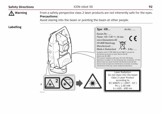
�Warning From a safety perspective class 2 laser products are not inherently safe for the eyes.Precautions:Avoid staring into the beam or pointing the beam at other people.
Labelling
TRACK_027
a
Type: iCR.... Art.No.: ......
Equipo.No.: ......Power: 12V / 7,4V ---, 1A maxLeica Geosystems AGCH-9435 HeerbruggManufactured: ....Made in Switzerland S.No.: ......Complies with 21 CFR 1040.10 and 1040.11 except for deviations pursuant to Laser Notice No.50, dated July 26, 2001.This device complies with part 15 of the FCC Rules. Operation is subject to the following two conditions: (1) This device may not cause harmful interference,and (2) this device must accept any interference received, including interference that may cause undesired operation.
Laser RadiationDo not stare into the beam
Class 2 Laser Productaccording to
IEC 60825-1 ( 2007 - 03 )Po 1.00 mW
λ = 620 - 690 nm

Safety Directions iCON robot 50 93
a) Laser beamb) Exit for laser beam
TRK
COMPWR
b
TRACK_028
a

94iCON robot 50Safety Directions
6.7 Electromagnetic Compatibility EMC
Description The term Electromagnetic Compatibility is taken to mean the capability of the product to function smoothly in an environment where electromagnetic radiation and elec-trostatic discharges are present, and without causing electromagnetic disturbances to other equipment.
�Warning Electromagnetic radiation can cause disturbances in other equipment.
Although the product meets the strict regulations and standards which are in force in this respect, Leica Geosystems cannot completely exclude the possibility that other equipment may be disturbed.
�Caution There is a risk that disturbances may be caused in other equipment if the product is used in conjunction with accessories from other manufacturers, for example field computers, personal computers, two-way radios, non-standard cables or external batteries.Precautions:Use only the equipment and accessories recommended by Leica Geosystems. When combined with the product, they meet the strict requirements stipulated by the guidelines and standards. When using computers and two-way radios, pay attention to the information about electromagnetic compatibility provided by the manufac-turer.

Safety Directions iCON robot 50 95
�Caution Disturbances caused by electromagnetic radiation can result in erroneous measure-ments.Although the product meets the strict regulations and standards which are in force in this respect, Leica Geosystems cannot completely exclude the possibility that the product may be disturbed by very intense electromagnetic radiation, for example, near radio transmitters, two-way radios or diesel generators.Precautions:Check the plausibility of results obtained under these conditions.
�Warning If the product is operated with connecting cables attached at only one of their two ends, for example external supply cables, interface cables, the permitted level of electromagnetic radiation may be exceeded and the correct functioning of other products may be impaired. Precautions:While the product is in use, connecting cables, for example product to external battery, product to computer, must be connected at both ends.

96iCON robot 50Safety Directions
Radios, Bluetooth Use of product with radio devices and Bluetooth:
�Warning Electromagnetic fields can cause disturbances in other equipment, in installations, in medical devices, for example pacemakers or hearing aids and in aircraft. It can also affect humans and animals.Precautions:Although the product meets the strict regulations and standards which are in force in this respect, Leica Geosystems cannot completely exclude the possibility that other equipment may be disturbed or that humans or animals may be affected.• Do not operate the product with radio or digital cellular phone devices in the
vicinity of filling stations or chemical installations, or in other areas where an explosion hazard exists.
• Do not operate the product with radio or digital cellular phone devices near to medical equipment.
• Do not operate the product with radio or digital cellular phone devices in aircraft.

Safety Directions iCON robot 50 97
6.8 FCC Statement, Applicable in U.S.
Applicability The greyed paragraph below is only applicable for products of the iCON robot 50 System without radio, digital cellular phone devices or Bluetooth.
�Warning This equipment has been tested and found to comply with the limits for a Class B digital device, pursuant to part 15 of the FCC rules.These limits are designed to provide reasonable protection against harmful interference in a residential installation.This equipment generates, uses and can radiate radio frequency energy and, if not installed and used in accordance with the instructions, may cause harmful interfer-ence to radio communications. However, there is no guarantee that interference will not occur in a particular installation.If this equipment does cause harmful interference to radio or television reception, which can be determined by turning the equipment off and on, the user is encour-aged to try to correct the interference by one or more of the following measures:• Reorient or relocate the receiving antenna.• Increase the separation between the equipment and the receiver.• Connect the equipment into an outlet on a circuit different from that to which
the receiver is connected.• Consult the dealer or an experienced radio/TV technician for help.

98iCON robot 50Safety Directions
�Warning Changes or modifications not expressly approved by Leica Geosystems for compli-ance could void the user's authority to operate the equipment.
Labelling iCON robot 50
TRACK_029
........ ..............
. . . . . . . .
. . . . . . . . . . . . . . . . . . . .
. . . . . . . . . . . . . . .
. . . . . . . .. . . . . . .
. . . . . . . . . . . . . . .
. . . . . . . . . . . . . . . . . . . . . .
This device complies with part 15 of the FCC Rules. Operation is subject to the following two conditions: (1) This device may not cause harm-ful interference, and (2) this device must accept any interference received, including inter-ference that may cause undesired operation.
Safety Directions iCON robot 50 99
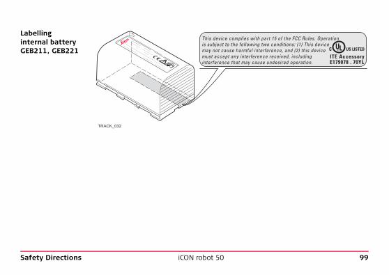
Labellinginternal battery GEB211, GEB221
TRACK_032
.................. ...............
.......................
...................... ................................
.................... ......................
....
..........
.................................................................................
This device complies with part 15 of the FCC Rules. Operation is subject to the following two conditions: (1) This device may not cause harmful interference, and (2) this device must accept any interference received, including interference that may cause undesired operation.

100iCON robot 50Safety Directions
LabellingCommunication-Handle
Available Communication-Handle types
The following CommunicationHandle types are available:• RH 1200 radio handle• CCD1 with WiFi• CCD2 with long range Bluetooth
TRACK_033
This device complies with part 15 of the FCC Rules. Operation is subject to the following two conditions: (1) This device may not cause harmful interference, and (2) this device must accept any interference received, including interference that may cause undesired operation.
Type: CCD.... Art.No.: ......Power: 7.4/12V---, nominal 0.2A max. 100mW EIRPLeica Geosystems AGCH-9435 HeerbruggManufactured: 2004Made in Switzerland This device contains a transmitter: FCC ID: HSW-2410M S.No.: XXXXXX
Safety Directions iCON robot 50 101
Exposure to Radio Frequency (RF) Signals
The wireless device is a radio transmitter and receiver. It is designed and manufac-tured not to exceed the emission limit for exposure to radio frequency (RF) energy set by the OET Bulletin 65 Supplement C / Ministry of Health (Canada), Safety Code 6. These limits are part of comprehensive guidelines and established permitted levels of RF energy for the general population. These guidelines are based on the safety standards previously set by international standard bodies. These standards include a substantial safety margin designed to assure the safety of all persons, regardless of age and health. This device and its antenna must not be co-located or operating in conjunction with any other antenna or transmitter. This device has been shown to be capable of compliance for localized specific absorp-tion rate (SAR) for uncontrolled environment / general public exposure limits specific in ANSI/IEEE C95.1-1992 and had been tested in accordance with the measurement procedures specified in IEEE Std. 1528-2003.
6.9 ICES-003 Statement, Applicable in Canada
�Warning This Class (B) digital apparatus complies with Canadian ICES-003.Cet appareil numérique de la classe (B) est conforme à la norme NMB-003 du Canada.

102iCON robot 50Technical Data
7 Technical Data7.1 Angle Measurement
Accuracy
Characteristics Absolute, continuous, diametric.
Type std. dev. Hz, V, ISO 17123-3 Display least count
["] [mgon] ["] [mgon]
iCON robot 50 2 0.6 0.1 0.5
iCON robot 50 5 1.5 0.1 0.5

Technical Data iCON robot 50 103
7.2 Distance Measurement with Reflectors (IR mode)
Range
Atmospheric conditions
Reflector Range A Range B Range C
[m] [ft] [m] [ft] [m] [ft]
Standard prism (GPR1) 1800 6000 3000 10000 3500 12000
3 standard prisms (GPR1) 2300 7500 4500 14700 5400 17700
360° prism (GRZ4, GRZ121, GRZ122, MPR122)
800 2600 1500 5000 2000 7000
360° Mini prism (GRZ101) 450 1500 800 2600 1000 3300
Mini prism (GMP101) 800 2600 1200 4000 2000 7000
Reflector tape60 mm x 60 mm
150 500 250 800 250 800
Shortest measuring distance: 1.5 m
A: Strong haze, visibility 5 km; or strong sunlight, severe heat shimmerB: Light haze, visibility about 20 km; or moderate sunlight, slight heat shimmerC: Overcast, no haze, visibility about 40 km; no heat shimmer

104iCON robot 50Technical Data
Measurements can be made to reflector tapes over the entire range without external ancillary optics.
Accuracy Accuracy refers to measurements to standard prisms.
Beam interruptions, severe heat shimmer and moving objects within the beam path can result in deviations of the specified accuracy.The display resolution is 0.1 mm.
Characteristics
EDMmeasuring mode
std. dev. ISO 17123-4, standard prism
std. dev. ISO 17123-4,tape
Measurement time, typical [s]
Standard 1 mm + 1.5 ppm 5 mm + 2 ppm 2.4
Fast 3 mm + 1.5 ppm 5 mm + 2 ppm 0.8
Tracking 3 mm + 1.5 ppm 5 mm + 2 ppm < 0.15
Averaging 1 mm + 1.5 ppm 5 mm + 2 ppm -
Principle: Phase measurementType: Coaxial, visible red laserCarrier wave: 660 nmMeasuring system: System analyzer basis 100 MHz - 150 MHz
Technical Data iCON robot 50 105
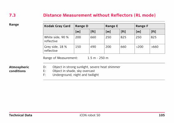
7.3 Distance Measurement without Reflectors (RL mode)
Range
Atmospheric conditions
Kodak Gray Card Range D Range E Range F
[m] [ft] [m] [ft] [m] [ft]
White side, 90 % reflective
200 660 250 825 250 825
Grey side, 18 % reflective
150 490 200 660 >200 >660
Range of Measurement: 1.5 m - 250 m
D: Object in strong sunlight, severe heat shimmerE: Object in shade, sky overcastF: Underground, night and twilight

106iCON robot 50Technical Data
Accuracy
Object in shade, sky overcast.Beam interruptions, severe heat shimmer and moving objects within the beam path can result in deviations of the specified accuracy.
Characteristics
Laser dot size
Standardmeasuring
std. dev.ISO 17123-4
Measure time, typical [s]
Measure time, maximum [s]
0 m - 250 m 2 mm + 2 ppm 3 - 6 12
Type: Coaxial, visible red laserCarrier wave: 658 nmMeasuring system PinPoint: System analyzer basis
100 MHz - 150 MHz
Distance [m] Laser dot size, approximately [mm]
at 20 7 x 14
at 100 12 x 40
at 200 25 x 80

Technical Data iCON robot 50 107
7.4 Automatic Target Recognition ATR
Range ATR/LOCK
ATR accuracy with the GPR1 prism
Reflector Range ATR mode Range Lock mode
[m] [ft] [m] [ft]
Standard prism (GPR1) 1000 3300 800 2600
360° prism (GRZ4, GRZ121, GRZ122, MPR122)
600 2000 500 1600
360° Mini prism (GRZ101) 350 1150 300 1000
Mini prism (GMP101) 500 1600 400 1300
Reflector tape60 mm x 60 mm
55 175 not qualified
Shortest measuring distance: 360° prism ATR: 1.5 mShortest measuring distance: 360° prism LOCK: 5 m
ATR angle accuracy Hz, V (std. dev. ISO 17123-3): 1 " (0.3 mgon)Base Positioning accuracy (std.dev.): ± 1 mm

108iCON robot 50Technical Data
System accuracy with ATR
• The accuracy with which the position of a prism can be determined with Automatic Target Recognition (ATR) depends on several factors such as internal ATR accu-racy, instrument angle accuracy, prism type, selected EDM measuring program and the external measuring conditions. The ATR has a basic standard deviation level of ± 1 mm. Above a certain distance, the instrument angle accuracy predominates and takes over the standard deviation of the ATR.
• The following graph shows the ATR standard deviation based on two different prism types, distances and instrument accuracies.
Leica 360° prism
Leica circular prism
mm ATR accuracy [mm]m Distance measurement [m]" Instrument angle accuracy ["]
20mm
m
181614121086
5”
3”
2”1.5”1”4
20
0
100
200
300
400
500
600
700
800
TRACK_034
Technical Data iCON robot 50 109
Maximum speed in lock mode
Searching
Characteristics
Maximum tangential speed: 5 m/s at 20 m; 25 m/s at 100 mMaximum radial speed with <EDM Mode: Tracking>: 5 m/s
Typical search time in field of view: 1.5 sField of view: 1°25’/1.55 gonDefinable search windows: Yes
Principle: Digital image processingType: Infrared laser

110iCON robot 50Technical Data
7.5 PowerSearch PS
Range
Measurements at the vertical limits of the fan or under unfavourable atmospheric conditions may reduce the maximum range. (*aligned to the instrument optimal)
Searching
Characteristics
Reflector Range PS
[m] [ft]
Standard prism (GPR1) 300 1000
360° prism (GRZ4, GRZ121, GRZ122, MPR122) 300* 1000*
Mini prism (GMP101) 100 330
Shortest measuring distance: 1.5 m
Typical search time: <10 sDefault search area: Hz: 400 gon, V: 40 gonDefinable search windows: Yes
Principle: Digital signal processingType: Infrared laser

Technical Data iCON robot 50 111
7.6 Conformity to National Regulations7.6.1 ConstructionRobot
Conformity to national regulations
Hereby, Leica Geosystems AG, declares that the iCON robot 50 is in compliance with the essential requirements and other relevant provi-sions of the applicable European Directives. The declaration of conformity may be consulted at http://www.leica-geosystems.com/ce.

112iCON robot 50Technical Data
7.6.2 Communication side cover with Bluetooth
Conformity to national regulations
Frequency band 2402 - 2480 MHz
Output power
Antenna
• FCC Part 15 (applicable in US)• Hereby, Leica Geosystems AG, declares that the Communication side cover with
Bluetooth is in compliance with the essential requirements and other relevant provisions of Directive 1999/5/EC. The declaration of conformity may be consulted at http://www.leica-geosystems.com/ce.
Class 1 equipment according European Directive 1999/5/EC (R&TTE) can be placed on the market and be put into service without restric-tions in any EEA Member state.
• The conformity for countries with other national regulations not covered by the FCC part 15 or European directive 1999/5/EC has to be approved prior to use and operation.
Bluetooth: 5 mW (Class 1)
Type Internal Microstrip antennaGain 1.5 dBi

Technical Data iCON robot 50 113
7.6.3 CommunicationHandle
Conformity to national regulations
Frequency band Limited to 2409 - 2435 MHz
Output power < 100mW (e.i.r.p.) (for CCD2 with long range Bluetooth : Class 1)
• FCC Part 15 (applicable in US)• Hereby, Leica Geosystems AG, declares that the CommunicationHandle is in
compliance with the essential requirements and other relevant provisions of Directive 1999/5/EC. The declaration of conformity may be consulted at http://www.leica-geosystems.com/ce.
Class 2 equipment according European Directive 1999/5/EC (R&TTE) for which following EEA Member States apply restrictions on the placing on the market or on the putting into service or require authorization for use:• France• Italy• Norway (if used in the geographical area within a radius
of 20km from the centre of Ny-Ålesund)• The conformity for countries with other national regulations not covered by the
FCC part 15 or European directive 1999/5/EC has to be approved prior to use and operation.

114iCON robot 50Technical Data
Antenna
Exposure to Radio Frequency (RF) Signals
The wireless device is a radio transmitter and receiver. It is designed and manufac-tured not to exceed the emission limit for exposure to radio frequency (RF) energy set by the OET Bulletin 65 Supplement C / Ministry of Health (Canada), Safety Code 6. These limits are part of comprehensive guidelines and established permitted levels of RF energy for the general population. These guidelines are based on the safety standards previously set by international standard bodies. These standards include a substantial safety margin designed to assure the safety of all persons, regardless of age and health. This device and its antenna must not be co-located or operating in conjunction with any other antenna or transmitter. This device has been shown to be capable of compliance for localized specific absorp-tion rate (SAR) for uncontrolled environment / general public exposure limits specific in ANSI/IEEE C95.1-1992 and had been tested in accordance with the measurement procedures specified in IEEE Std. 1528-2003.
Type: Patch antenna (omnidirectional)Gain: 2 dBiConnector: SMB

Technical Data iCON robot 50 115
7.7 General Technical Data7.7.1 iCON robot 50 Technical Data
Telescope
Compensator
Level
Magnification: 30 xClear objective diameter: 40 mmFocusing: 1.7 m/5.6 ft to infinityField of view: 1°30’/1.66 gon
2.7 m at 100 m
Type Setting accuracy Setting range
["] [mgon] [’] [gon]
iCON robot 50 1 0.3 4 0.07
iCON robot 50 1.5 0.5 4 0.07
Circular level sensitivity: 6’/2 mmElectronic level resolution: 2"

116iCON robot 50Technical Data
Instrument Ports Port Name Description
Port 1 Port 1 • 5 pin LEMO-0 for power, communication, data transfer.• This port is located at the base of the instrument.
Port 2 Handle • Hotshoe connection for CommunicationHandle with RCS.• This port is located on top of Communication side cover.
Port 3 BT • Bluetooth module for communication.• This port is housed within Communication side cover.

Technical Data iCON robot 50 117
InstrumentDimensions
Weight
TRACK_035
196
mm
328
mm
226 mm
101.5 mm101.5 mm
196
mm
328
mm
203 mm
TRACK_036
Instrument: 4.8 - 5.5 kgTribrach: 0.8 kgInternal battery GEB221: 0.2 kg

118iCON robot 50Technical Data
Laser plummet
Drives
Motorisation
Power
Internal battery
External battery
Type: Visible red laser class 2Location: In standing axis of instrumentAccuracy: Deviation from plumbline:
1.5 mm at 1.5 m instrument heightDiameter of laser point: 2.5 mm at 1.5 m instrument height
Type: Endless horizontal and vertical drives
Maximum rotating speed: 50 gon/s
External supply voltage: Nominal voltage 12.8 V DC, Range 11.5 V-13.5 V
Type: Li-IonVoltage: 7.4 VCapacity: GEB221: 4.4 AhTypical operating time: 5 - 8 h
Type: NiMHVoltage: 12 VCapacity: GEB171: 8.0 AhTypical operating time: 18 - 24 h

Technical Data iCON robot 50 119
Environmental specifications
Temperature
Protection against water, dust and sand
Humidity
Type Operating temperature [°C] Storage temperature [°C]
iCON robot 50 -20 to +50 -40 to +70
Leica CompactFlash cards, all sizes
-40 to +80 -40 to +80
Battery internal -20 to +55 -40 to +70
Bluetooth -30 to +60 -40 to +80
Type Protection
iCON robot 50 IP54 (IEC 60529)
Type Protection
iCON robot 50 Max 95 % non condensingThe effects of condensation are to be effectively counter-acted by periodically drying out the instrument.

120iCON robot 50Technical Data
Reflectors
There are no special prisms required for ATR or for PS.
Electronic Guide Light EGL
Type Additive Constant [mm] ATR PS
Standard prism, GPR1 0.0 yes yes
Mini prism, GMP101 +17.5 yes yes
360° prism,GRZ4, GRZ121, GRZ122
+23.1 yes yes
360° MA prism MPR122 +28.1 yes yes
360° Mini prism +30.0 yes not recommended
Reflector tape S, M, L +34.4 yes no
Reflectorless +34.4 no no
Working range: 5 - 150 mPositioning accuracy: 5 cm at 100 m

Technical Data iCON robot 50 121
Automaticcorrections
The following automatic corrections are made:• Line of sight error • Vertical index error• Tilting axis error • Standing axis tilt• Earth curvature • Refraction• Circle eccentricity • ATR zero point error• Compensator index error

122iCON robot 50Technical Data
7.8 Scale Correction
Use By entering a scale correction, reductions proportional to distance can be taken into account.• Atmospheric correction• Reduction to mean sea level• Projection distortion
Atmospheric correction ΔD1
The slope distance displayed is correct if the scale correction in ppm, mm/km, which has been entered corresponds to the atmospheric conditions prevailing at the time of the measurement.
The atmospheric correction includes:• Adjustments for air pressure• Air temperature• Relative humidity
For highest precision distance measurements, the atmospheric correction should be determined with an accuracy of 1 ppm. The following parameters must be redeter-mined: • Air temperature to 1°C• Air pressure to 3 mbar• Relative humidity to 20 %

Technical Data iCON robot 50 123
Air humidity The air humidity influences the distance measurement if the climate is extremely hot and damp.For high precision measurements, the relative humidity must be measured and entered along with the air pressure and the temperature.
Air humidity correction
Index n
ppm Air humidity correction [mm/km]% Relative humidity [%]C° Air temperature [°C]
ppm+5
+1
+2
+3
+4
+0-10-20 0 10 20 30 40 50 °C
100%
80%60%40%
20%
TRACK_037
Type Index n carrier wave [nm]
combined EDM 1.0002863 660

124iCON robot 50Technical Data
The index n is calculated from the formula of Barrel and Sears, and is valid for:
Formulas Formula for visible red laser
ΔD1 Atmospheric correction [ppm]p Air pressure [mbar]t Air temperature [°C]h Relative humidity [%]
α
x (7.5 * t/(237.3 + t)) + 0.7857
If the basic value of 60 % relative humidity as used by the EDM is retained, the maximum possible error in the calculated atmospheric correction is 2 ppm, 2 mm/km.
Air pressure p: 1013.25 mbarAir temperature t: 12 °CRelative air humidity h: 60 %
ΔD1= 286.269 -0.29528 · p
· 10x4.126 · 10-4 · h-
TRACK_052
1273.15

Technical Data iCON robot 50 125
Reduction to mean sea level ΔD2
The values for D2 are always negative and are derived from the following formula:
Projectiondistortion ΔD3
The magnitude of the projection distortion is in accordance with the projection system used in a particular country, for which official tables are generally available. The following formula is valid for cylindrical projections such as that of Gauss-Krüger:
In countries where the scale factor is not unity, this formula cannot be directly applied.
ΔD2 Reduction to mean sea level [ppm]H Height of EDM above sea level [m]
R 6.378 * 106 m
ΔD2= - HR
· 106
TRACK_053
ΔD3 Projection distortion [ppm]X Northing, distance from projection
zero line with the scale factor 1 [km]
R 6.378 * 106 m
ΔD3= X2
2R2 · 106
TRACK_054

126iCON robot 50Technical Data
Atmospheric corrections °C
Atmospheric corrections in ppm with temperature [°C], air pressure [mb] and height [m] at 60 % relative humidity.
TRACK_038
-40-35-30-25
-20-15-1
0-50
51015
2025
3035
4045
5055
6065
7075
8085
909510
010511
011512
012513
013514
0
50°C50°C
40°C40°C
30°C30°C
20°C20°C
10°C10°C
0°C 0°C
-10°C-10°C
-20°C-20°C550 mb
5000 m 4500
600 650 700 750 800 850 900 950 1000 1050 mb
550 mb 600 650 700 750 800 850 900 950 1000 1050 mb
4000 3500 3000 2500 2000 1500 1000 500 0 m

Technical Data iCON robot 50 127
Atmospheric correction F
Atmospheric correction in ppm with temperature [F], air pressure [inch Hg] and height [ft] at 60 % relative humidity.
TRACK_039
130°F
120°F
110°F
100°F
90°F
80°F
70°F
60°F
50°F
40°F
30°F
20°F
10°F
0°F
-10°F
-20°F
130°F
120°F
110°F
100°F
90°F
80°F
70°F
60°F
50°F
40°F
30°F
20°F
10°F
0°F
-10°F
-20°F16
[ ft ]
17 18 19 20 21 22 23 24 25 26 27 28 29 30 31 32 inch Hg
16 17 18 19 20 21 22 23 24 25 26 27 28 29 30 31 32 inch Hg
1600
015
00014
00013
00012
000
1100
010
000
9000
8000
7000
6000
5000
4000
3000
2000
1000 o f
t
-15
-20
-25
-30
-35
-40
-45
-50
-55
-10-5
05101520
253035
4045
505560
6570
7580
8590
9510010
511011
512012
513013
514014
5
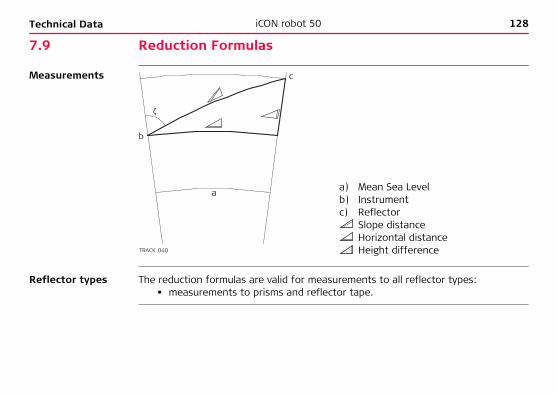
128iCON robot 50Technical Data
7.9 Reduction Formulas
Measurements
Reflector types The reduction formulas are valid for measurements to all reflector types:• measurements to prisms and reflector tape.
a) Mean Sea Levelb) Instrument c) Reflector
Slope distanceHorizontal distanceHeight difference
c
a
b
TRACK_040
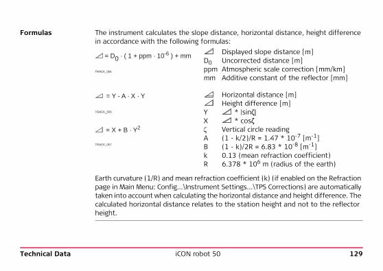
Technical Data iCON robot 50 129
Formulas The instrument calculates the slope distance, horizontal distance, height difference in accordance with the following formulas:
Earth curvature (1/R) and mean refraction coefficient (k) (if enabled on the Refraction page in Main Menu: Config...\Instrument Settings...\TPS Corrections) are automatically taken into account when calculating the horizontal distance and height difference. The calculated horizontal distance relates to the station height and not to the reflector height.
Displayed slope distance [m]D0 Uncorrected distance [m]ppm Atmospheric scale correction [mm/km]mm Additive constant of the reflector [mm]
Horizontal distance [m]Height difference [m]
Y * |sinζ| X * cosζ Vertical circle readingA (1 - k/2)/R = 1.47 * 10-7 [m-1]B (1 - k)/2R = 6.83 * 10-8 [m-1]k 0.13 (mean refraction coefficient)R 6.378 * 106 m (radius of the earth)
= D0 · ( 1 + ppm · 10-6 ) + mm
TRACK_055
= Y - A · X · Y
TRACK_056
= X + B · Y2
TRACK_057

130iCON robot 50Technical Data
Distancemeasuring program Averaging
In the distance measuring program Averaging, the following values are displayed:D Slope distance as arithmetic mean of all measurementss Standard deviation of a single measurementn Number of measurements
These values are calculated as follows:Slope distance as arithmetic mean of all measurements
Σ SumDi Single slope distance measurementn Number of measurements
s Standard deviation of a single slope distance measurement
Σ SumSlope distance as arithmetic mean of all measurements
Di Single slope distance measurementn Number of distance measurements
· ∑ DiD = 1n
n
i = 1
TRACK_058
s = (Di - D)2
n - 1=
Di2 -
n - 1
( Di)2 ∑
n i = 1
∑ n
i = 1 ∑
n i = 1
1n
TRACK_059

Technical Data iCON robot 50 131
The standard deviation of the arithmetic mean of the distance can be calculated as follows:
Standard deviation of the arith-metic mean of the distance
s Standard deviation of a single measurement
n Number of measurements
SD = ns
TRACK_060
132iCON robot 50International Limited Warranty, Soft-ware License Agreement
8 International Limited Warranty, Software License Agreement
International Limited Warranty
This product is subject to the terms and conditions set out in the International Limited Warranty which you can download from the Leica Geosystems home page at http://www.leica-geosystems.com/internationalwarranty or collect from your Leica Geosystems distributor.
The foregoing warranty is exclusive and is in lieu of all other warranties, terms or conditions, express or implied, either in fact or by operation of law, statutory or otherwise, including warranties, terms or conditions of merchantability, fitness for a particular purpose, satisfactory quality and non-infringement, all of which are expressly disclaimed.
Software License Agreement
This product contains software that is preinstalled on the product, or that is supplied to you on a data carrier medium, or that can be downloaded by you online pursuant to prior authorization from Leica Geosystems. Such software is protected by copy-right and other laws and its use is defined and regulated by the Leica Geosystems Software License Agreement, which covers aspects such as, but not limited to, Scope of the License, Warranty, Intellectual Property Rights, Limitation of Liability, Exclusion of other Assurances, Governing Law and Place of Jurisdiction. Please make sure, that at any time you fully comply with the terms and conditions of the Leica Geosystems Software License Agreement.

International Limited Warranty, Soft-ware License Agreement
iCON robot 50 133
Such agreement is provided together with all products and can also be referred to and downloaded at the Leica Geosystems home page at http://www.leica-geosystems.com/swlicense or collected from your Leica Geosystems distributor.
You must not install or use the software unless you have read and accepted the terms and conditions of the Leica Geosystems Software License Agreement. Installa-tion or use of the software or any part thereof, is deemed to be an acceptance of all the terms and conditions of such license agreement. If you do not agree to all or some of the terms of such license agreement, you may not download, install or use the software and you must return the unused software together with its accompa-nying documentation and the purchase receipt to the dealer from whom you purchased the product within ten (10) days of purchase to obtain a full refund of the purchase price.

134iCON robot 50End User Licence Agreement EULA
9 End User Licence Agreement EULAEULA terms • You have acquired a device CC60/CC61 or CC50 that includes software licenced by
Leica Geosystems from an affiliate of Microsoft Corporation ("MS"). Those installed software products of MS origin, as well as associated media, printed materials, and "online" or electronic documentation ("SOFTWARE") are protected by international intellectual property laws and treaties. The SOFTWARE is licenced, not sold. All rights reserved.
• IF YOU DO NOT AGREE TO THIS END USER LICENCE AGREEMENT ("EULA"), DO NOT USE THE DEVICE OR COPY THE SOFTWARE, INSTEAD, PROMPTLY CONTACT Leica Geosystems FOR INSTRUCTIONS ON RETURN OF THE UNUSED DEVICE(S) FOR A REFUND. ANY USE OF THE SOFTWARE, INCLUDING BUT NOT LIMITED TO USE ON THE DEVICE, WILL CONSTITUTE YOUR AGREEMENT TO THIS EULA (OR RATIFICATION OF ANY PREVIOUS CONSENT).
• GRANT OF SOFTWARE LICENCE. This EULA grants you the following licence:• You may use the SOFTWARE only on the DEVICE.• NOT FAULT TOLERANT. THE SOFTWARE IS NOT FAULT TOLERANT. Leica
Geosystems HAS INDEPENDENTLY DETERMINED HOW TO USE THE SOFTWARE IN THE DEVICE, AND MS HAS RELIED UPON Leica Geosystems TO CONDUCT SUFFICIENT TESTING TO DETERMINE THAT THE SOFTWARE IS SUITABLE FOR SUCH USE.

End User Licence Agreement EULA iCON robot 50 135
• NO WARRANTIES FOR THE SOFTWARE. THE SOFTWARE is provided "AS IS" and with all faults. THE ENTIRE RISK AS TO SATISFACTORY QUALITY, PERFORMNCE, ACCURACY, AND EFFORT (INCLUDING LACK OF NEGLIGENCE) IS WITH YOU. ALSO, THERE IS NO WARRANTY AGAINST INTERFERENCE WITH YOUR ENJOYMENT OF THE SOFTWARE OF AGAINST INFRINGEMENT. IF YOU HAVE RECEIVED ANY WARRANTIES REGARDING THE DEVICE OR THE SOFT-WARE, THOSE WARRANTIES DO NOT ORIGINATE FROM, AND ARE NOT BINDING ON, MS.
• No Liability for Certain Damages. EXCEPT AS PROHIBITED BY LAW, MS SHALL HAVE NO LIABILITY FOR ANY INDIRECT, SPECIAL, CONSEQUENTIAL OR INCIDENTAL DAMAGES ARISING FROM OR IN CONNECTION WITH THE USE OR PERFORMANCE OF THE SOFTWARE. THIS LIMITATION SHALL APPLY EVEN IF ANY REMEDY FAILS FOF ITS ESSENTIAL PURPOSE. IN NO EVENT SHALL MS BE LIABLE FOR ANY AMOUNT IN EXCESS OF U.S. TWO HUNDRED FIFTY DOLLARS (U.S.$250.00).
• Limitations on Reverse Engineering, Decompilation, and Disassembly. You may not reverse engineer, decompile, or disassemble the SOFTWARE, except and only to the extent that such activity is expressly permitted by appli-cable law notwithstanding these limitation.
• SOFTWARE TRANSFER ALLOWED BUT WITH RESTRICTIONS. You may permanently transfer rights under this EULA only as part of a permanent sale or transfer of the Device, and only if the recipient agrees to this EULA. If the SOFTWARE is an upgrade, any transfer must also include all prior versions of the SOFTWARE.

136iCON robot 50End User Licence Agreement EULA
• EXPORT RESTRICTIONS. You acknowledge that SOFTWARE is subject to U.S. and European Union export jurisdiction. You agree to comply with all applicable international and national laws that apply to the SOFTWARE, including the U.S. Export Administration Regulations, as well as end-user, end-use and destina-tion restrictions issued by U.S. and other governments. For additional informa-tion see http://www.microsoft.com/exporting/.

End User Licence Agreement EULA iCON robot 50 137

138iCON robot 50Index
Index
AAbbreviations ...................................................... 10Acclimatise to the ambient temperature ............. 51Accuracy
Angle measurement ..................................... 102IR mode ....................................................... 104RL mode ...................................................... 106
AdjustmentCombined (l, t, i, c and ATR) ........................... 53Electronic ....................................................... 48Inspecting the laser plummet ......................... 57Mechanical ..................................................... 49Of circular level on instrument ....................... 54Of circular level on prism pole ........................ 56Of circular level on tribrach ............................ 54Of laser plummet ........................................... 57Preparation .................................................... 51
Angle Measurement .......................................... 102Antenna
Communication side cover ........................... 112CommunicationHandle ................................. 114
Autodetect behaviour ..........................................33CommunicationHandle ....................................33Radios/Modems ..............................................33
Automatic Corrections .......................................121Automatic Target Recognition ATR
Accuracy with the GPR1 prism ......................107Description .....................................................86Positioning of crosshairs ................................52System accuracy ...........................................108
BBattery
For instrument ...............................................41Overview ........................................................38Technical data GEB171 .................................118Technical data GEB221 .................................118

Index iCON robot 50 139
CCheck & Adjust ................................................... 48Cleaning and Drying ............................................ 62Communication side cover
Graphical overview with CommunicationHandle ..23Technical data .............................................. 112
CommunicationHandleDescription .................................................... 12LED indicators ................................................ 36Setup for remote control ............................... 34Technical data .............................................. 113
CompactFlash Card ....................................... 15, 43Insert card ..................................................... 43Remove card .................................................. 43Safety instructions ......................................... 43
Compensator .................................................... 115Container Contents
For Controller and accessories ................. 19, 20For instrument ......................................... 17, 18
Control Panel ...................................................... 24Corrections
Automatic .................................................... 121Scale ............................................................ 122
DData Storage .......................................................15Dimensions
Of instrument ..............................................117Distance Measurement
IR mode .......................................................103RL mode .......................................................105
Documentation .....................................................4Drives ................................................................118
EElectromagnetic Compatibility EMC ......................94Electronic Adjustment ..........................................48Electronic Distance Measurement EDM
Description .....................................................12Electronic Guide Light EGL
Description ...............................................13, 90Technical data ..............................................120
End User Licence Agreement .............................134Environmental specifications .............................119EULA .................................................................134

140iCON robot 50Index
FFCC Statement .................................................... 97Formulas, reduction .......................................... 128Frequency Band
Communication side cover ........................... 112CommunicationHandle ................................. 113
GGuidelines for Correct Results ............................. 45
HHazards of Use ................................................... 70
IInstrument
Components .................................................. 21Dimensions .................................................. 117Ports ............................................................ 116Technical data .............................................. 115Turn on and turn off ...................................... 27Weight ......................................................... 117
Instrument SetupConventional .................................................. 30For remote control ......................................... 34
Intended Use ...................................................... 65
LLabelling
ConstructionRobot .........................................98Laser Classification ..............................................79
Automatic Target Recognition ATR .................86Electronic Guide Light EGL ..............................90Integrated Distancer, Visible Laser ..................82Laser Plummet ...............................................91PowerSearch PS .............................................88
Laser PlummetAdjustment ....................................................57Technical data ..............................................118
LED IndicatorsFor CommunicationHandle ..............................36For ConstructionRobot ...................................25
Level .................................................................115
MMaintenance .......................................................63Manual
Validity of user manual .....................................3Mechanical Adjustment ........................................49

Index iCON robot 50 141
OON/OFF button ................................................... 24Output Power
Communication side cover ........................... 112CommunicationHandle ................................. 113
PPorts ................................................................. 116Power Supply ...................................................... 16PowerSearch PS ................................................ 110Precise Measurements ........................................ 49
RReduction Formulas .......................................... 128Reflectors ......................................................... 120Responsibilities ................................................... 68
SSafety Directions ................................................ 64Scale Correction ................................................ 122Service, of tripod ................................................ 59Setup
Conventional .................................................. 30For remote control ......................................... 34
SoftwareApplication programs .....................................14Software type ................................................14Software upload .............................................14System software ............................................14
Software Concept ...............................................14Specifications, environmental
ConstructionRobot .......................................119Status
CommunicationHandle ....................................36Storage ...............................................................61System Concept ..................................................14

142iCON robot 50Index
TTechnical Data .................................................. 102Telescope ......................................................... 115Temperature
Battery InternalOperating ............................................... 119Storage ................................................... 119
BluetoothOperating ............................................... 119Storage ................................................... 119
CompactFlash CardOperating ............................................... 119Storage ................................................... 119
InstrumentOperating ............................................... 119Storage ................................................... 119
Terminology ........................................................ 10Transport ............................................................ 60Tripod, service of ................................................ 59
WWeight
Of instrument .............................................. 117

Index iCON robot 50 143

Total Quality Management: Our commitment to total customer satisfaction.
Leica Geosystems AG, Heerbrugg, Switzerland, has been certified as being equipped with a quality system which meets the International Standards of Quality Management and Quality Systems (ISO standard 9001) and Environmental Management Systems (ISO standard 14001).
Ask your local Leica Geosystems dealer for more information about our TQM program.
7936
28-1
.0.0
enO
rigin
al t
ext
Prin
ted
in S
witz
erla
nd ©
201
1 Le
ica
Geo
syst
ems
AG, H
eerb
rugg
, Sw
itzer
land
Survey Instrument Sales24037 AcaciaRedford, MI 48239USAPhone +1-313-535-5252
www.surveyinstrumentsales.com