lessons and experiences learned applying model based
TRANSCRIPT
© 2018 Electric Power Research Institute, Inc. All rights reserved.
Dr. Carl Elks, Co-PI, Virginia Commonwealth UniversityDr. Ashraf Tantawy, Research Professor, Virginia Commonwealth UniversityMatt Gibson, Program PI, EPRIRick Hite, Smitha Gautham, Chris Deloglos, Athira Jayakumar, Shawkat Khairullah- Virginia Commonwealth UniversityJason Moore, MathWorks
Andrew Nack, Paragon Inc.
Oct. 8th 2018
Lessons and Experiences Learned Applying Model Based Engineering to Safety Critical FPGA Designs
A US-DOE Funded Project under the NEET Program
11th International Workshop on the Application of FPGAs in NPPs
2 © 2018 Electric Power Research Institute, Inc. All rights reserved.
Who we are: Virginia Commonwealth University Department
of Electrical and Computer Engineering– Located in Richmond, VA, USA– +30,000 enrolled students in university
Dependable and Secure Cyber-Physical Systems Lab– Dr. Carl R. Elks, Ph.D. Emal: [email protected]
– Our lab is multidisciplinary, comprising faculty and research members whose expertise spans across hardware architectures, dependability and cyber-security, Unmanned Autonomous Systems, Nuclear Energy Instrumentation and Control, MEMs devices, and advanced sensors.
– Our lab has a strong focus on experimental methods and practices, we develop techniques and methods that are applied to real world systems or verified with actual data.
3 © 2018 Electric Power Research Institute, Inc. All rights reserved.
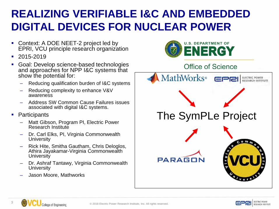
REALIZING VERIFIABLE I&C AND EMBEDDED DIGITAL DEVICES FOR NUCLEAR POWER Context: A DOE NEET-2 project led by
EPRI, VCU principle research organization 2015-2019 Goal: Develop science-based technologies
and approaches for NPP I&C systems that show the potential for:– Reducing qualification burden of I&C systems– Reducing complexity to enhance V&V
awareness– Address SW Common Cause Failures issues
associated with digital I&C systems. Participants
– Matt Gibson, Program PI, Electric Power Research Institute
– Dr. Carl Elks, PI, Virginia Commonwealth University
– Rick Hite, Smitha Gautham, Chris Deloglos, Athira Jayakamar-Virginia Commonwealth University
– Dr. Ashraf Tantawy, Virginia Commonwealth University
– Jason Moore, Mathworks
The SymPLe Project
4 © 2018 Electric Power Research Institute, Inc. All rights reserved.
Research Perspective
What’s the problem we are trying to address?– Safety Critical SW based systems expensive to
develop– Certification/Licensing is even more expensive I&C systems in the context of nuclear power
may not need to be derivatives of software intensive systems and by extension, not carrying the complexity associated with the SW intensive systems. Our approach called SymPLe is to rethink digital
I&C from a perspective of three views: Simplicity, Extensibility and Verifiability.

5 © 2018 Electric Power Research Institute, Inc. All rights reserved.
Comparative View of I&C “Stacks”
6 © 2018 Electric Power Research Institute, Inc. All rights reserved.
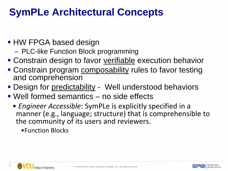
SymPLe Architectural Concepts
HW FPGA based design– PLC-like Function Block programming
Constrain design to favor verifiable execution behavior Constrain program composability rules to favor testing
and comprehension Design for predictability - Well understood behaviors Well formed semantics – no side effects• Engineer Accessible: SymPLe is explicitly specified in a manner (e.g., language; structure) that is comprehensible to the community of its users and reviewers. •Function Blocks
7 © 2018 Electric Power Research Institute, Inc. All rights reserved.
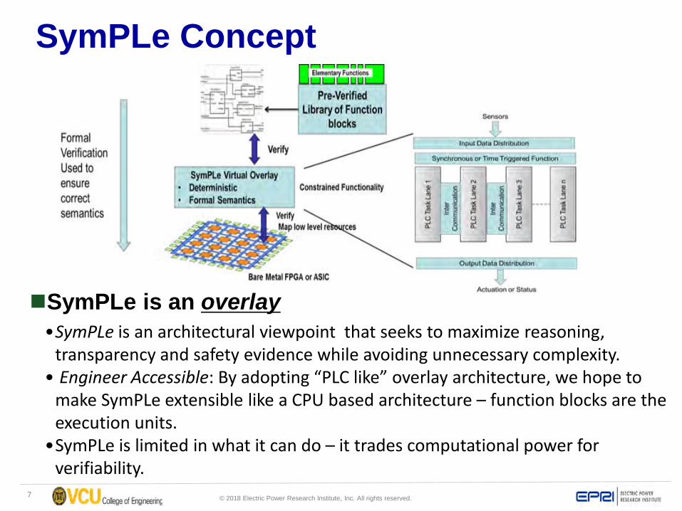
SymPLe Concept
SymPLe is an overlay•SymPLe is an architectural viewpoint that seeks to maximize reasoning,
transparency and safety evidence while avoiding unnecessary complexity. • Engineer Accessible: By adopting “PLC like” overlay architecture, we hope to
make SymPLe extensible like a CPU based architecture – function blocks are the execution units.
•SymPLe is limited in what it can do – it trades computational power for verifiability.
8 © 2018 Electric Power Research Institute, Inc. All rights reserved.
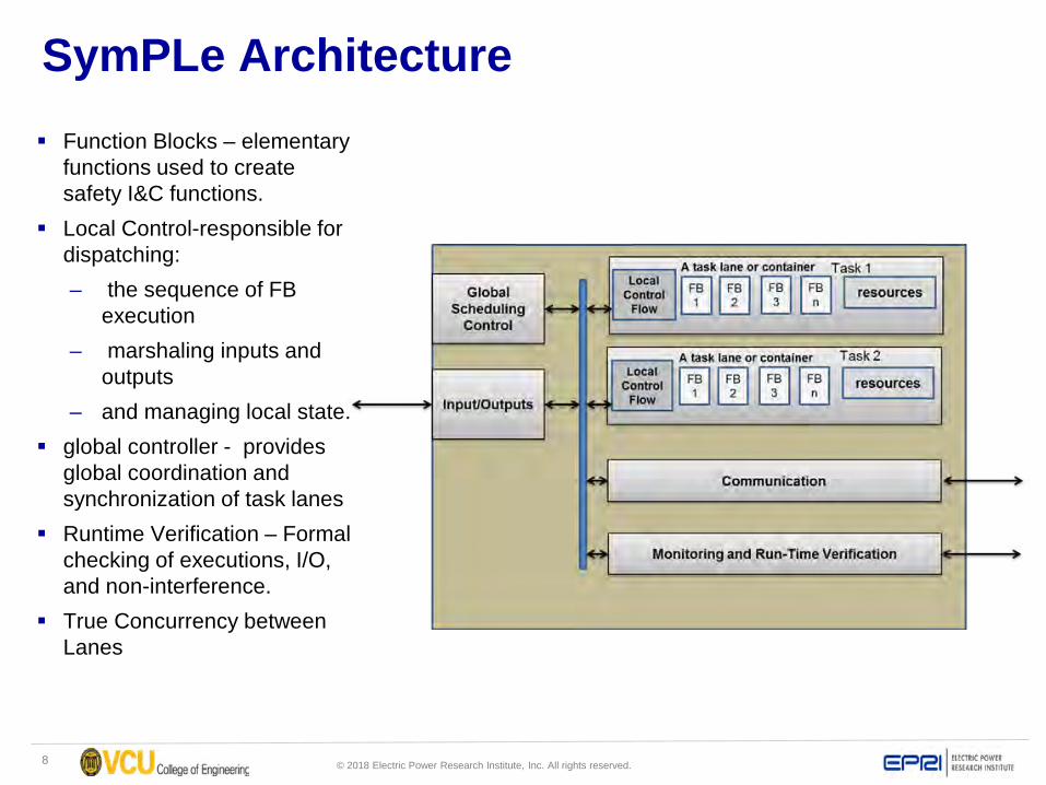
SymPLe Architecture Function Blocks – elementary
functions used to create safety I&C functions.
Local Control-responsible for dispatching:– the sequence of FB
execution– marshaling inputs and
outputs– and managing local state.
global controller - provides global coordination and synchronization of task lanes
Runtime Verification – Formal checking of executions, I/O, and non-interference.
True Concurrency between Lanes

9 © 2018 Electric Power Research Institute, Inc. All rights reserved.
Function Block Architecture
Common architecture for all SymPLe function blocks– Separation of control
and dataflow with clear and defined interconnections
– Formal Semantics– Inspired by IEC-61499
SymPLe architecture variants differ in the control path of the generic function block– Autonomous Function
Block– Lite Function Block
Local ScheduleControl
10 © 2018 Electric Power Research Institute, Inc. All rights reserved.
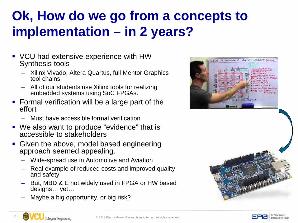
Ok, How do we go from a concepts to implementation – in 2 years? VCU had extensive experience with HW
Synthesis tools– Xilinx Vivado, Altera Quartus, full Mentor Graphics
tool chains– All of our students use Xilinx tools for realizing
embedded systems using SoC FPGAs. Formal verification will be a large part of the
effort– Must have accessible formal verification
We also want to produce “evidence” that is accessible to stakeholders
Given the above, model based engineering approach seemed appealing. – Wide-spread use in Automotive and Aviation – Real example of reduced costs and improved quality
and safety– But, MBD & E not widely used in FPGA or HW based
designs… yet…– Maybe a big opportunity, or big risk?
11 © 2018 Electric Power Research Institute, Inc. All rights reserved.
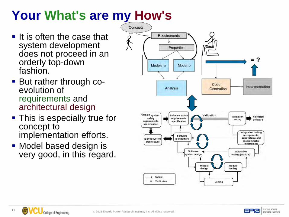
Your What's are my How's It is often the case that
system development does not proceed in an orderly top-down fashion. But rather through co-
evolution of requirements and architectural design This is especially true for
concept to implementation efforts. Model based design is
very good, in this regard.
12 © 2018 Electric Power Research Institute, Inc. All rights reserved.
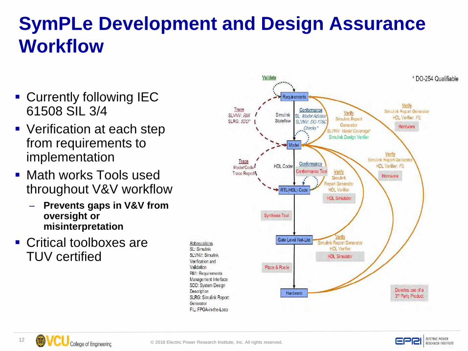
SymPLe Development and Design Assurance Workflow
Currently following IEC 61508 SIL 3/4
Verification at each step from requirements to implementation
Math works Tools used throughout V&V workflow– Prevents gaps in V&V from
oversight or misinterpretation
Critical toolboxes are TUV certified
13 © 2018 Electric Power Research Institute, Inc. All rights reserved.
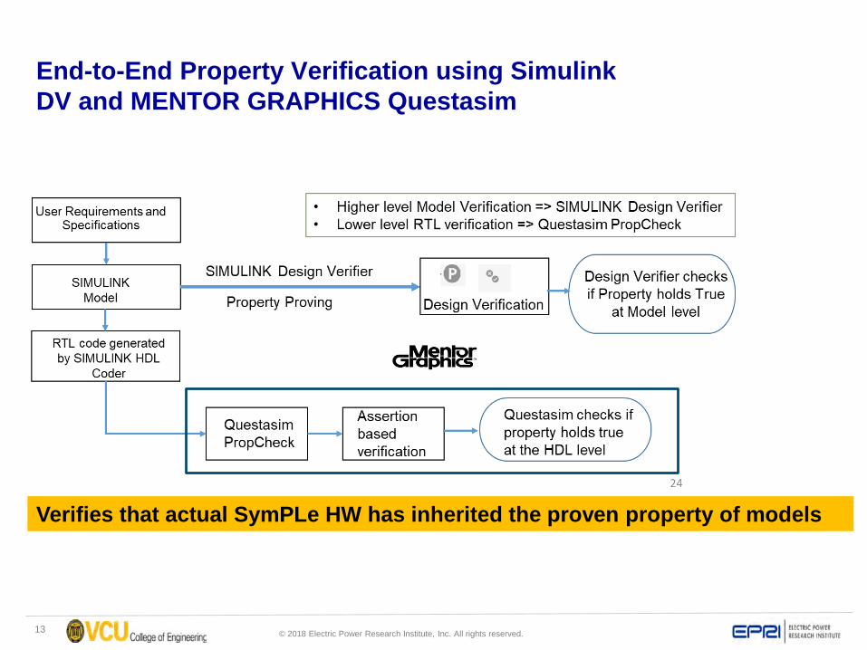
End-to-End Property Verification using Simulink DV and MENTOR GRAPHICS Questasim
Verifies that actual SymPLe HW has inherited the proven property of models
14 © 2018 Electric Power Research Institute, Inc. All rights reserved.
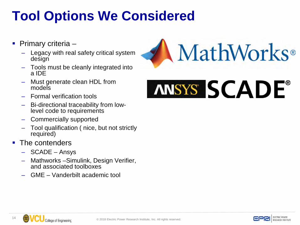
Tool Options We Considered
Primary criteria –– Legacy with real safety critical system
design– Tools must be cleanly integrated into
a IDE– Must generate clean HDL from
models– Formal verification tools– Bi-directional traceability from low-
level code to requirements– Commercially supported – Tool qualification ( nice, but not strictly
required) The contenders
– SCADE – Ansys– Mathworks –Simulink, Design Verifier,
and associated toolboxes– GME – Vanderbilt academic tool
15 © 2018 Electric Power Research Institute, Inc. All rights reserved.
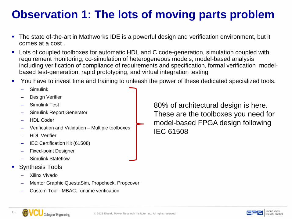
Observation 1: The lots of moving parts problem
The state of-the-art in Mathworks IDE is a powerful design and verification environment, but it comes at a cost .
Lots of coupled toolboxes for automatic HDL and C code-generation, simulation coupled with requirement monitoring, co-simulation of heterogeneous models, model-based analysis including verification of compliance of requirements and specification, formal verification model-based test-generation, rapid prototyping, and virtual integration testing
You have to invest time and training to unleash the power of these dedicated specialized tools. – Simulink– Design Verifier– Simulink Test– Simulink Report Generator– HDL Coder– Verification and Validation – Multiple toolboxes– HDL Verifier– IEC Certification Kit (61508)– Fixed-point Designer– Simulink Stateflow
Synthesis Tools– Xilinx Vivado– Mentor Graphic QuestaSim, Propcheck, Propcover– Custom Tool - MBAC: runtime verification
80% of architectural design is here. These are the toolboxes you need for model-based FPGA design following IEC 61508
16 © 2018 Electric Power Research Institute, Inc. All rights reserved.
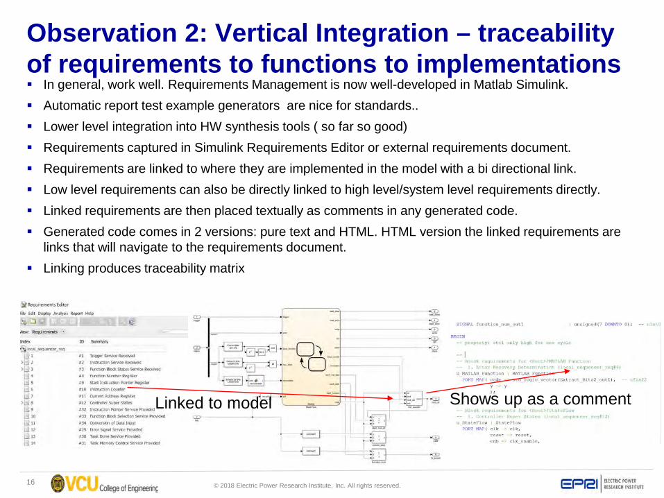
Observation 2: Vertical Integration – traceability of requirements to functions to implementations In general, work well. Requirements Management is now well-developed in Matlab Simulink. Automatic report test example generators are nice for standards.. Lower level integration into HW synthesis tools ( so far so good) Requirements captured in Simulink Requirements Editor or external requirements document. Requirements are linked to where they are implemented in the model with a bi directional link. Low level requirements can also be directly linked to high level/system level requirements directly. Linked requirements are then placed textually as comments in any generated code. Generated code comes in 2 versions: pure text and HTML. HTML version the linked requirements are
links that will navigate to the requirements document. Linking produces traceability matrix
Linked to model Shows up as a comment
17 © 2018 Electric Power Research Institute, Inc. All rights reserved.
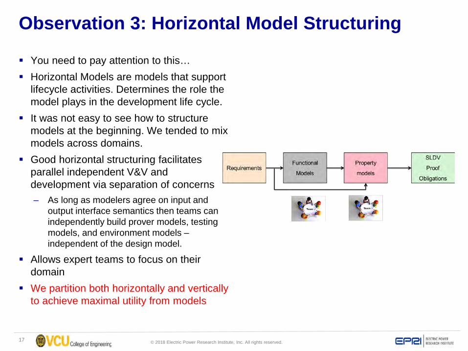
Observation 3: Horizontal Model Structuring
You need to pay attention to this… Horizontal Models are models that support
lifecycle activities. Determines the role the model plays in the development life cycle.
It was not easy to see how to structure models at the beginning. We tended to mix models across domains.
Good horizontal structuring facilitates parallel independent V&V and development via separation of concerns– As long as modelers agree on input and
output interface semantics then teams can independently build prover models, testing models, and environment models –independent of the design model.
Allows expert teams to focus on their domain
We partition both horizontally and vertically to achieve maximal utility from models

18 © 2018 Electric Power Research Institute, Inc. All rights reserved.
Example: How the functional and Property models play togetherDesign Verifier A collection of verification tools, of which the strongest is formal model checking, and K-induction. Used for Property Proving: Properties are written for critical conditions that has to hold true in the
design. Design verifier formally verifies by checking the properties in the entire state space for all inputs. If the properties are falsified, detailed report with counter examples is generated
Design verifier can also be used to generate test cases to increase coverage
Model and the Verification Subsystem having the Properties that have to be verified by the Design Verifier
Functional Model
Property Model
19 © 2018 Electric Power Research Institute, Inc. All rights reserved.
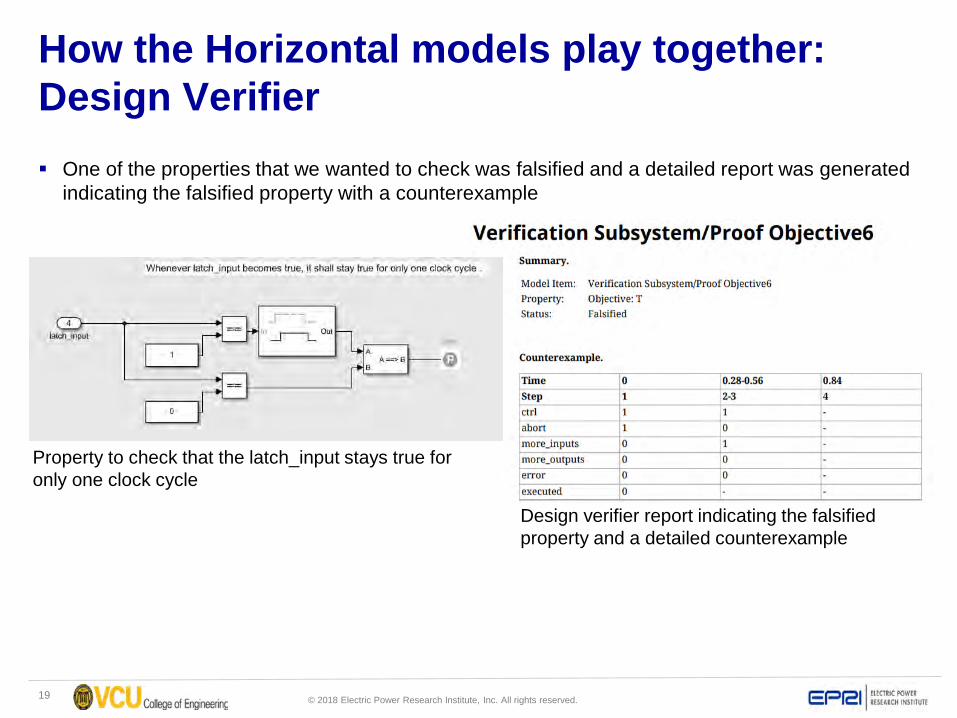
How the Horizontal models play together: Design Verifier One of the properties that we wanted to check was falsified and a detailed report was generated
indicating the falsified property with a counterexample
Property to check that the latch_input stays true for only one clock cycle
Design verifier report indicating the falsified property and a detailed counterexample

20 © 2018 Electric Power Research Institute, Inc. All rights reserved.
Example: How the models play together
Fig: Counterexample indicating the input conditions for which the property failed
21 © 2018 Electric Power Research Institute, Inc. All rights reserved.
Observation 4: Usability Across Specialization Domains
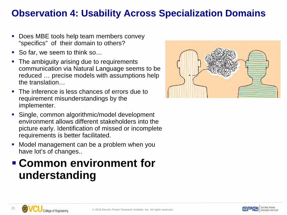
Does MBE tools help team members convey “specifics” of their domain to others?
So far, we seem to think so… The ambiguity arising due to requirements
communication via Natural Language seems to be reduced … precise models with assumptions help the translation…
The inference is less chances of errors due to requirement misunderstandings by the implementer.
Single, common algorithmic/model development environment allows different stakeholders into the picture early. Identification of missed or incomplete requirements is better facilitated.
Model management can be a problem when you have lot’s of changes..
Common environment for understanding
22 © 2018 Electric Power Research Institute, Inc. All rights reserved.
Observation 5: Common environment for understanding
Very well – could be a key to regulator/supplier evidence communication
Single, common algorithmic/model development environment allows different stakeholders into the picture early. Identification of missed or incomplete requirements is better facilitated.
No mix of prototyping languages Commonality fosters sharing, algorithm/utility reuse Use a single, secure, collaborative, web-based sharing repository
(github/Gitlab, bitbucket, etc…) Functional models allow low-level designs and implementations to be
critically reviewed with better comprehension.
23 © 2018 Electric Power Research Institute, Inc. All rights reserved.
Observation 6: Evidence based Artifacts are useful for reviews Very well, needs some help from lower level Synthesis tools. We found that models, and the results/data are very good for confirming or refuting a
claim. Requirements, sub-requirements and assumptions are explicitly chained in all models Testing, formal verification in the Simulink When you get to VHDL and transfer to HW synthesis you may need to check to see if you
can trace bi-directionally. Cite preliminary results for Paragon.
IMAGE REQ DOC TO THE MODEL TO THE TEST RESULTS TO THE PROVER RESULTS
PROP CHECK IMAGE
24 © 2018 Electric Power Research Institute, Inc. All rights reserved.
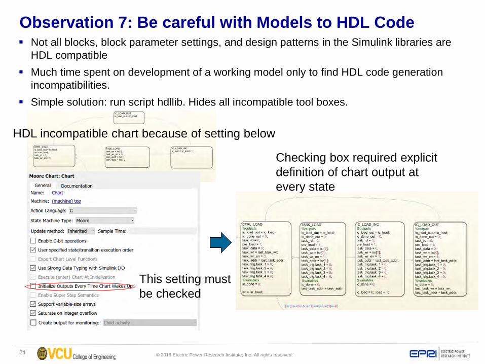
Observation 7: Be careful with Models to HDL Code Not all blocks, block parameter settings, and design patterns in the Simulink libraries are
HDL compatible Much time spent on development of a working model only to find HDL code generation
incompatibilities. Simple solution: run script hdllib. Hides all incompatible tool boxes.
HDL incompatible chart because of setting below
This setting must be checked
Checking box required explicit definition of chart output at every state
25 © 2018 Electric Power Research Institute, Inc. All rights reserved.
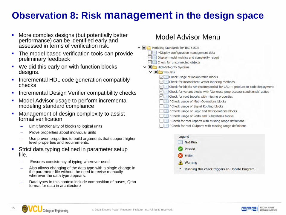
Observation 8: Risk management in the design space
More complex designs (but potentially better performance) can be identified early and assessed in terms of verification risk.
The model based verification tools can provide preliminary feedback
We did this early on with function blocks designs.
Incremental HDL code generation compatibly checks
Incremental Design Verifier compatibility checks Model Advisor usage to perform incremental
modeling standard compliance Management of design complexity to assist
formal verification– Limit functionality of blocks to logical units– Prove properties about individual units– Use proven properties to build arguments that support higher
level properties and requirements.
Strict data typing defined in parameter setup file.– Ensures consistency of typing wherever used. – Also allows changing of the data type with a single change in
the parameter file without the need to revise manually wherever the data type appears.
– Data types in this context include composition of buses, Qmnformat for data in architecture
Model Advisor Menu
26 © 2018 Electric Power Research Institute, Inc. All rights reserved.
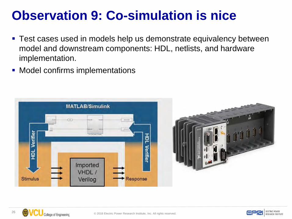
Observation 9: Co-simulation is nice Test cases used in models help us demonstrate equivalency between
model and downstream components: HDL, netlists, and hardware implementation.
Model confirms implementations
27 © 2018 Electric Power Research Institute, Inc. All rights reserved.
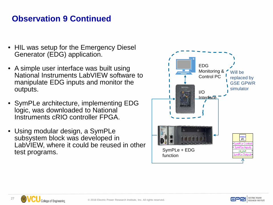
Observation 9 Continued
• HIL was setup for the Emergency Diesel Generator (EDG) application.
• A simple user interface was built using National Instruments LabVIEW software to manipulate EDG inputs and monitor the outputs.
• SymPLe architecture, implementing EDG logic, was downloaded to National Instruments cRIO controller FPGA.
• Using modular design, a SymPLesubsystem block was developed in LabVIEW, where it could be reused in other test programs.
EDG Monitoring & Control PC
SymPLe + EDG function
I/O Interface
Will be replaced by GSE GPWR simulator
28 © 2018 Electric Power Research Institute, Inc. All rights reserved.
Overall Experience Summary Generally very pleased with the outcomes so far. Investment is necessary to reap the full benefits
– Does not eliminate HW synthesis tools, but allows reasoning to be “moved” up to where more stakeholders are inclusive
– Much more formal in it’s approach. Which is a good thing…
It’s a paradigm shift from traditional “platform” based design Great for making the “evidence” accessible and transparent to
reviewers, stakeholders. – Paragon Inc is reviewing the models, evidences, and results as part of a “mock” CGD.
We are finding difficult bugs, which is a metric in itself.. Would have been very difficult to achieve project goals in traditional HW
synthesis tools Not perfect, room for improvement, but the benefits (at least to us) are
very compelling.
29 © 2018 Electric Power Research Institute, Inc. All rights reserved.
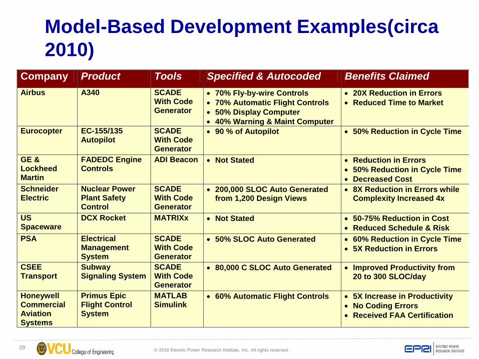
Model-Based Development Examples(circa 2010)
Company Product Tools Specified & Autocoded Benefits Claimed Airbus A340 SCADE
With Code Generator
• 70% Fly-by-wire Controls • 70% Automatic Flight Controls • 50% Display Computer • 40% Warning & Maint Computer
• 20X Reduction in Errors • Reduced Time to Market
Eurocopter EC-155/135 Autopilot
SCADE With Code Generator
• 90 % of Autopilot
• 50% Reduction in Cycle Time
GE & Lockheed Martin
FADEDC Engine Controls
ADI Beacon • Not Stated
• Reduction in Errors • 50% Reduction in Cycle Time • Decreased Cost
Schneider Electric
Nuclear Power Plant Safety Control
SCADE With Code Generator
• 200,000 SLOC Auto Generated from 1,200 Design Views
• 8X Reduction in Errors while Complexity Increased 4x
US Spaceware
DCX Rocket MATRIXx • Not Stated
• 50-75% Reduction in Cost • Reduced Schedule & Risk
PSA Electrical Management System
SCADE With Code Generator
• 50% SLOC Auto Generated • 60% Reduction in Cycle Time • 5X Reduction in Errors
CSEE Transport
Subway Signaling System
SCADE With Code Generator
• 80,000 C SLOC Auto Generated • Improved Productivity from 20 to 300 SLOC/day
Honeywell Commercial Aviation Systems
Primus Epic Flight Control System
MATLAB Simulink
• 60% Automatic Flight Controls • 5X Increase in Productivity • No Coding Errors • Received FAA Certification

30 © 2018 Electric Power Research Institute, Inc. All rights reserved.
Requirements
Properties
Models a
Analysis
Concepts
Model b
Code Generation Implementation
= ?
31 © 2018 Electric Power Research Institute, Inc. All rights reserved.
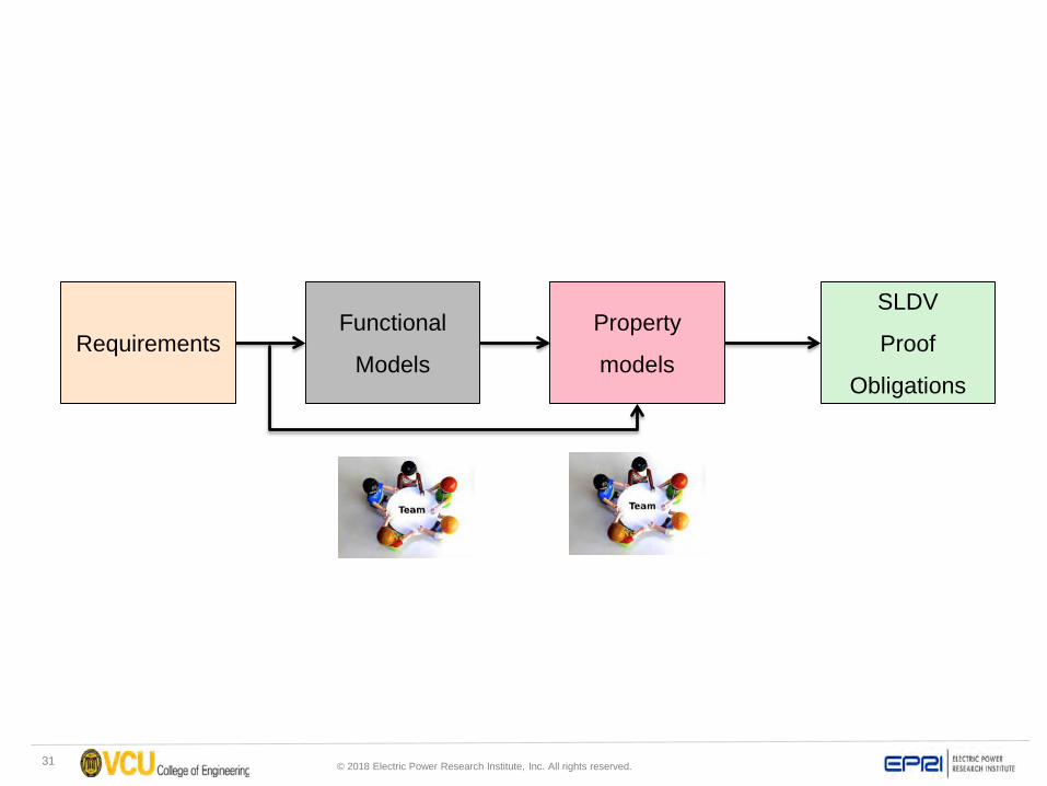
Functional
Models
SLDV
Proof
Obligations
Property
modelsRequirements
32 © 2018 Electric Power Research Institute, Inc. All rights reserved.
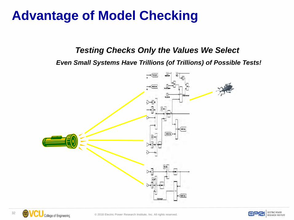
Advantage of Model Checking
Testing Checks Only the Values We SelectEven Small Systems Have Trillions (of Trillions) of Possible Tests!
33 © 2018 Electric Power Research Institute, Inc. All rights reserved.
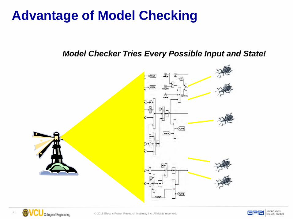
Advantage of Model Checking
Model Checker Tries Every Possible Input and State!