levelflex fmp50 technical information
TRANSCRIPT
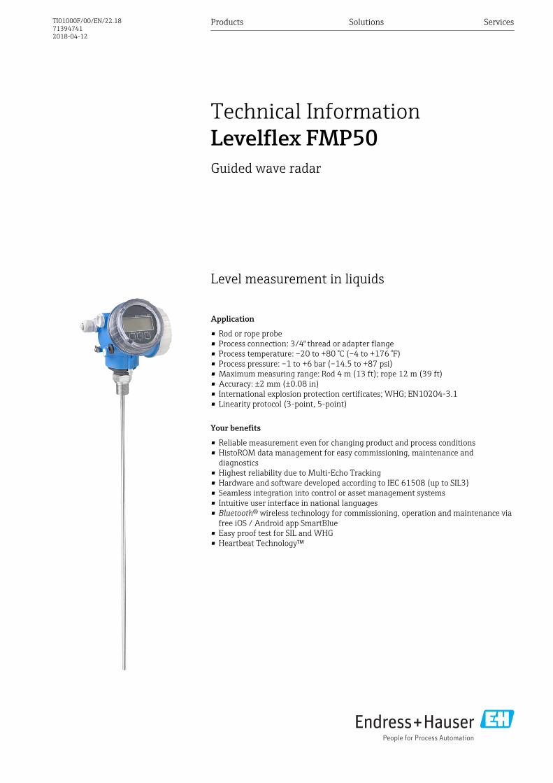
Level measurement in liquids
Application
• Rod or rope probe• Process connection: 3/4" thread or adapter flange• Process temperature: –20 to +80 °C (–4 to +176 °F)• Process pressure: –1 to +6 bar (–14.5 to +87 psi)• Maximum measuring range: Rod 4 m (13 ft); rope 12 m (39 ft)• Accuracy: ±2 mm (±0.08 in)• International explosion protection certificates; WHG; EN10204-3.1• Linearity protocol (3-point, 5-point)
Your benefits
• Reliable measurement even for changing product and process conditions• HistoROM data management for easy commissioning, maintenance and
diagnostics• Highest reliability due to Multi-Echo Tracking• Hardware and software developed according to IEC 61508 (up to SIL3)• Seamless integration into control or asset management systems• Intuitive user interface in national languages• Bluetooth® wireless technology for commissioning, operation and maintenance via
free iOS / Android app SmartBlue• Easy proof test for SIL and WHG• Heartbeat Technology™
Products Solutions Services
Technical InformationLevelflex FMP50Guided wave radar
TI01000F/00/EN/22.18713947412018-04-12
Levelflex FMP50
2 Endress+Hauser
Table of contents
Important document information . . . . . . . . . . . . . . . 4Symbols . . . . . . . . . . . . . . . . . . . . . . . . . . . . . . . . . . . . 4Terms and abbreviations . . . . . . . . . . . . . . . . . . . . . . . . 6Registered trademarks . . . . . . . . . . . . . . . . . . . . . . . . . . 7
Function and system design . . . . . . . . . . . . . . . . . . . 8Measuring principle . . . . . . . . . . . . . . . . . . . . . . . . . . . . 8Measuring system . . . . . . . . . . . . . . . . . . . . . . . . . . . . 11
Input . . . . . . . . . . . . . . . . . . . . . . . . . . . . . . . . . . . . 12Measured variable . . . . . . . . . . . . . . . . . . . . . . . . . . . . 12Measuring range . . . . . . . . . . . . . . . . . . . . . . . . . . . . . 12Blocking distance . . . . . . . . . . . . . . . . . . . . . . . . . . . . 13Measuring frequency spectrum . . . . . . . . . . . . . . . . . . . 13
Output . . . . . . . . . . . . . . . . . . . . . . . . . . . . . . . . . . 14Output signal . . . . . . . . . . . . . . . . . . . . . . . . . . . . . . . 14Signal on alarm . . . . . . . . . . . . . . . . . . . . . . . . . . . . . . 15Linearization . . . . . . . . . . . . . . . . . . . . . . . . . . . . . . . 15Galvanic isolation . . . . . . . . . . . . . . . . . . . . . . . . . . . . 15Protocol-specific data . . . . . . . . . . . . . . . . . . . . . . . . . . 16
Power supply . . . . . . . . . . . . . . . . . . . . . . . . . . . . . 21Terminal assignment . . . . . . . . . . . . . . . . . . . . . . . . . . 21Device plug connectors . . . . . . . . . . . . . . . . . . . . . . . . . 29Power supply . . . . . . . . . . . . . . . . . . . . . . . . . . . . . . . 30Power consumption . . . . . . . . . . . . . . . . . . . . . . . . . . . 33Current consumption . . . . . . . . . . . . . . . . . . . . . . . . . . 33Power supply failure . . . . . . . . . . . . . . . . . . . . . . . . . . 34Potential equalization . . . . . . . . . . . . . . . . . . . . . . . . . 34Terminals . . . . . . . . . . . . . . . . . . . . . . . . . . . . . . . . . 34Cable entries . . . . . . . . . . . . . . . . . . . . . . . . . . . . . . . 34Cable specification . . . . . . . . . . . . . . . . . . . . . . . . . . . . 34Overvoltage protection . . . . . . . . . . . . . . . . . . . . . . . . . 35
Performance characteristics . . . . . . . . . . . . . . . . . . 36Reference operating conditions . . . . . . . . . . . . . . . . . . . 36Reference accuracy . . . . . . . . . . . . . . . . . . . . . . . . . . . 36Resolution . . . . . . . . . . . . . . . . . . . . . . . . . . . . . . . . . 37Reaction time . . . . . . . . . . . . . . . . . . . . . . . . . . . . . . . 38Influence of ambient temperature . . . . . . . . . . . . . . . . . 38
Mounting . . . . . . . . . . . . . . . . . . . . . . . . . . . . . . . . 39Mounting requirements . . . . . . . . . . . . . . . . . . . . . . . . 39
Operating conditions: Environment . . . . . . . . . . . . 54Ambient temperature range . . . . . . . . . . . . . . . . . . . . . 54Ambient temperature limits . . . . . . . . . . . . . . . . . . . . . 54Storage temperature . . . . . . . . . . . . . . . . . . . . . . . . . . 56Climate class . . . . . . . . . . . . . . . . . . . . . . . . . . . . . . . 56Altitude according to IEC61010-1 Ed.3 . . . . . . . . . . . . . . 56Degree of protection . . . . . . . . . . . . . . . . . . . . . . . . . . 56Vibration resistance . . . . . . . . . . . . . . . . . . . . . . . . . . . 56Cleaning the probe . . . . . . . . . . . . . . . . . . . . . . . . . . . 56Electromagnetic compatibility (EMC) . . . . . . . . . . . . . . . 56
Process . . . . . . . . . . . . . . . . . . . . . . . . . . . . . . . . . . 57Process temperature range . . . . . . . . . . . . . . . . . . . . . . 57Process pressure range . . . . . . . . . . . . . . . . . . . . . . . . . 57Dielectric constant (DC) . . . . . . . . . . . . . . . . . . . . . . . . 57Expansion of the rope probes through temperature . . . . . . 57
Mechanical construction . . . . . . . . . . . . . . . . . . . . 58Dimensions . . . . . . . . . . . . . . . . . . . . . . . . . . . . . . . . 58Tolerance of probe length . . . . . . . . . . . . . . . . . . . . . . . 61Shortening probes . . . . . . . . . . . . . . . . . . . . . . . . . . . . 61Weight . . . . . . . . . . . . . . . . . . . . . . . . . . . . . . . . . . . 62Materials: GT19 housing (plastic) . . . . . . . . . . . . . . . . . . 63Materials: GT20 housing (die-cast aluminum, powder-coated) . . . . . . . . . . . . . . . . . . . . . . . . . . . . . . . . . . . 64Materials: Process connection . . . . . . . . . . . . . . . . . . . . 66Materials: Probe . . . . . . . . . . . . . . . . . . . . . . . . . . . . . 67Materials: Mounting bracket . . . . . . . . . . . . . . . . . . . . . 68Materials: Adapter and cable for remote sensor . . . . . . . . 69Materials: Weather protection cover . . . . . . . . . . . . . . . . 70
Operability . . . . . . . . . . . . . . . . . . . . . . . . . . . . . . . 71Operating concept . . . . . . . . . . . . . . . . . . . . . . . . . . . . 71Local operation . . . . . . . . . . . . . . . . . . . . . . . . . . . . . . 72Operation with remote display and operating moduleFHX50 . . . . . . . . . . . . . . . . . . . . . . . . . . . . . . . . . . . 72Operation via Bluetooth® wireless technology . . . . . . . . . . 73Remote operation . . . . . . . . . . . . . . . . . . . . . . . . . . . . 74Integration in tank gauging system . . . . . . . . . . . . . . . . . 77SupplyCare inventory management software . . . . . . . . . . 78
Certificates and approvals . . . . . . . . . . . . . . . . . . . 81CE mark . . . . . . . . . . . . . . . . . . . . . . . . . . . . . . . . . . . 81RoHS . . . . . . . . . . . . . . . . . . . . . . . . . . . . . . . . . . . . . 81RCM-Tick marking . . . . . . . . . . . . . . . . . . . . . . . . . . . . 81Ex approval . . . . . . . . . . . . . . . . . . . . . . . . . . . . . . . . 81Dual seal according to ANSI/ISA 12.27.01 . . . . . . . . . . . . 81Functional Safety . . . . . . . . . . . . . . . . . . . . . . . . . . . . 81Overfill prevention . . . . . . . . . . . . . . . . . . . . . . . . . . . . 81Pressure equipment with allowable pressure≤ 200 bar (2 900 psi) . . . . . . . . . . . . . . . . . . . . . . . . . . 81Telecommunications . . . . . . . . . . . . . . . . . . . . . . . . . . 81Test, Certificate . . . . . . . . . . . . . . . . . . . . . . . . . . . . . . 82Product documentation on paper . . . . . . . . . . . . . . . . . . 82Other standards and guidelines . . . . . . . . . . . . . . . . . . . 83
Ordering information . . . . . . . . . . . . . . . . . . . . . . . 84Ordering information . . . . . . . . . . . . . . . . . . . . . . . . . . 843-point linearity protocol . . . . . . . . . . . . . . . . . . . . . . . 855-point linearity protocol . . . . . . . . . . . . . . . . . . . . . . . 86Customized parametrization . . . . . . . . . . . . . . . . . . . . . 87Tagging (TAG) . . . . . . . . . . . . . . . . . . . . . . . . . . . . . . 87
Application Packages . . . . . . . . . . . . . . . . . . . . . . . 88Heartbeat Diagnostics . . . . . . . . . . . . . . . . . . . . . . . . . 88Heartbeat Verification . . . . . . . . . . . . . . . . . . . . . . . . . 89Heartbeat Monitoring . . . . . . . . . . . . . . . . . . . . . . . . . 90

Levelflex FMP50
Endress+Hauser 3
Accessories . . . . . . . . . . . . . . . . . . . . . . . . . . . . . . . 91Device-specific accessories . . . . . . . . . . . . . . . . . . . . . . 91Communication-specific accessories . . . . . . . . . . . . . . . . 98Service-specific accessories . . . . . . . . . . . . . . . . . . . . . . 99System components . . . . . . . . . . . . . . . . . . . . . . . . . . . 99
Documentation . . . . . . . . . . . . . . . . . . . . . . . . . . . 100Standard documentation . . . . . . . . . . . . . . . . . . . . . . . 100Supplementary documentation . . . . . . . . . . . . . . . . . . . 100Safety Instructions (XA) . . . . . . . . . . . . . . . . . . . . . . . 101
Levelflex FMP50
4 Endress+Hauser
Important document information
Symbols Safety symbols
Symbol Meaning
DANGER
DANGER!This symbol alerts you to a dangerous situation. Failure to avoid this situation willresult in serious or fatal injury.
WARNING
WARNING!This symbol alerts you to a dangerous situation. Failure to avoid this situation canresult in serious or fatal injury.
CAUTION
CAUTION!This symbol alerts you to a dangerous situation. Failure to avoid this situation canresult in minor or medium injury.
NOTICE
NOTE!This symbol contains information on procedures and other facts which do not result inpersonal injury.
Electrical symbols
Symbol Meaning
Direct current
Alternating current
Direct current and alternating current
Ground connectionA grounded terminal which, as far as the operator is concerned, is grounded via agrounding system.
Protective Earth (PE)A terminal which must be connected to ground prior to establishing any otherconnections.
The ground terminals are situated inside and outside the device:• Inner ground terminal: Connects the protectiv earth to the mains supply.• Outer ground terminal: Connects the device to the plant grounding system.
Symbols for certain types of information
Symbol Meaning
PermittedProcedures, processes or actions that are permitted.
PreferredProcedures, processes or actions that are preferred.
ForbiddenProcedures, processes or actions that are forbidden.
TipIndicates additional information.
Reference to documentation.
A Reference to page.
Reference to graphic.
Visual inspection.
Levelflex FMP50
Endress+Hauser 5
Symbols in graphics
Symbol Meaning
1, 2, 3 ... Item numbers
1. , 2. , 3.… Series of steps
A, B, C, ... Views
A-A, B-B, C-C, ... Sections
-Hazardous areaIndicates a hazardous area.
.Safe area (non-hazardous area)Indicates the non-hazardous area.
Symbols at the device
Symbol Meaning
Safety instructionsObserve the safety instructions contained in the associated Operating Instructions.
Temperature resistance of the connection cablesSpecifies the minimum value of the temperature resistance of the connection cables.
Levelflex FMP50
6 Endress+Hauser
Terms and abbreviations Term/abbreviation Explanation
BA Document type "Operating Instructions"
KA Document type "Brief Operating Instructions"
TI Document type "Technical Information"
SD Document type "Special Documentation"
XA Document type "Safety Instructions"
PN Nominal pressure
MWP Maximum Working PressureThe MWP can also be found on the nameplate.
ToF Time of Flight
FieldCare Scalable software tool for device configuration and integrated plant asset managementsolutions
DeviceCare Universal configuration software for Endress+Hauser HART, PROFIBUS,FOUNDATION Fieldbus and Ethernet field devices
DTM Device Type Manager
DD Device Description for HART communication protocol
εr (DC value) Relative dielectric constant
Operating tool The term "operating tool" is used in place of the following operating software:• FieldCare / DeviceCare, for operation via HART communication and PC• SmartBlue (app), for operation using an Android or iOS smartphone or tablet.
BD Blocking Distance; no signals are analyzed within the BD.
PLC Programmable Logic Controller
CDI Common Data Interface
PFS Pulse Frequence Status (Switching output)
MBP Manchester Bus Powered
PDU Protocol Data Unit
Levelflex FMP50
Endress+Hauser 7
Registered trademarks HART®
Registered trademark of the FieldComm Group, Austin, USA
PROFIBUS®
Registered trademark of the PROFIBUS User Organization, Karlsruhe, Germany
FOUNDATIONTM FieldbusRegistered trademark of the FieldComm Group, Austin, Texas, USABluetooth®The Bluetooth® word mark and logos are registered trademarks owned by the Bluetooth SIG, Inc. andany use of such marks by Endress+Hauser is under license. Other trademarks and trade names arethose of their respective owners.Apple®Apple, the Apple logo, iPhone, and iPod touch are trademarks of Apple Inc., registered in the U.S.andother countries. App Store is a service mark of Apple Inc.Android®Android, Google Play and the Google Play logo are trademarks of Google Inc.
KALREZ®, VITON®
Registered trademark of DuPont Performance Elastomers L.L.C., Wilmington, USA
TEFLON®
Registered trademark of E.I. DuPont de Nemours & Co., Wilmington, USA
TRI CLAMP®
Registered trademark of Alfa Laval Inc., Kenosha, USA
Levelflex FMP50
8 Endress+Hauser
Function and system design
Measuring principle Basic principles
The Levelflex is a "downward-looking" measuring system that functions according to the ToF method(ToF = Time of Flight). The distance from the reference point to the product surface is measured.High-frequency pulses are injected to a probe and led along the probe. The pulses are reflected bythe product surface, received by the electronic evaluation unit and converted into level information.This method is also known as TDR (Time Domain Reflectometry).
F
L
D
E
20 mA
100%
4 mA
0%
LN
R
A0011360
1 Parameters for level measurement with the guided radar
LN Probe lengthD DistanceL LevelR Reference point of measurementE Empty calibration (= zero)F Full calibration (= span)
If, for rope probes, the DC value is less than 7, then measurement is not possible in the area ofthe straining weight (0 to 250 mm (0 to 9.84 in) from end of probe; lower blocking distance).
Levelflex FMP50
Endress+Hauser 9
Dielectric constant
The dielectric constant (DC) of the medium has a direct impact on the degree of reflection of thehighfrequency pulses. In the case of large DC values, such as for water or ammonia, there is strongpulse reflection while, with low DC values, such as for hydrocarbons, weak pulse reflection isexperienced.
Input
The reflected pulses are transmitted from the probe to the electronics. There, a microprocessoranalyzes the signals and identifies the level echo which was generated by the reflection of the high-frequency pulses at the product surface. This clear signal detection system benefits from over 30years' experience with pulse time-of-flight procedures that have been integrated into thedevelopment of the PulseMaster® software.
The distance D to the product surface is proportional to the time of flight t of the impulse:
D = c · t/2,
where c is the speed of light.
Based on the known empty distance E, the level L is calculated:
L = E – D
The reference point R of the measurement is located at the process connection. For details see thedimensional drawing:FMP50: → 60The Levelflex possesses functions for interference echo suppression that can be activated by the user.They guarantee that interference echoes from e.g. internals and struts are not interpreted as levelechoes.
Output
The Levelflex is preset at the factory to the probe length ordered so that in most cases only theapplication parameters that automatically adapt the device to the measuring conditions need to beentered. For models with a current output, the factory adjustment for zero point E and span F is 4mA and 20 mA, for digital outputs and the display module 0 % and 100 %. A linearization functionwith max. 32 points, which is based on a table entered manually or semi-automatically, can beactivated on site or via remote operation. This function allows the level to be converted into units ofvolume or mass, for example.
Levelflex FMP50
10 Endress+Hauser
Life cycle of the product
Engineering• Universal measuring principle• Measurement unaffected by medium properties• Hardware and software developed according to SIL IEC 61508• Genuine, direct interface measurementProcurement• Endress+Hauser being the world market leader in level measurement guarantees asset protection• Worldwide support and serviceInstallation• Special tools are not required• Reverse polarity protection• Modern, detachable terminals• Main electronics protected by a separate connection compartmentCommissioning• Fast, menu-guided commissioning in only 6 steps• Plain text display in national languages reduces the risk of error or confusion• Direct local access of all parameters• Short instruction manual at the deviceOperation• Multi-echo tracking: Reliable measurement through self-learning echo-search algorithms taking
into account the short-term and long-term history in order to check the found echoes forplausibility and to suppress interference echoes.
• Diagnostics in accordance with NAMUR NE107Maintenance• HistoROM: Data backup for instrument settings and measured values• Exact instrument and process diagnosis to assist fast decisions with clear details concerning
remedies• Intuitive, menu-guided operating concept in national languages saves costs for training,
maintenance and operation• Cover of the electronics compartment can be opened in hazardous areasRetirement• Order code translation for subsequent models• RoHS-conforming (Restriction of certain Hazardous Substances), unleaded soldering of electronic
components• Environmentally sound recycling concept
Levelflex FMP50
Endress+Hauser 11
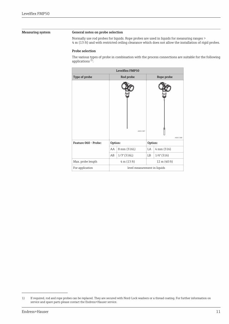
Measuring system General notes on probe selection
Normally use rod probes for liquids. Rope probes are used in liquids for measuring ranges >4 m (13 ft) and with restricted ceiling clearance which does not allow the installation of rigid probes.
Probe selection
The various types of probe in combination with the process connections are suitable for the followingapplications 1):
Levelflex FMP50
Type of probe Rod probe Rope probe
A0011387
A0011388
Feature 060 - Probe: Option: Option:
AA 8 mm (316L) LA 4 mm (316)
AB 1/3" (316L) LB 1/6" (316)
Max. probe length 4 m (13 ft) 12 m (40 ft)
For application level measurement in liquids
1) If required, rod and rope probes can be replaced. They are secured with Nord-Lock washers or a thread coating. For further information onservice and spare parts please contact the Endress+Hauser service.
Levelflex FMP50
12 Endress+Hauser
Input
Measured variable The measured variable is the distance between the reference point and the product surface.
Subject to the empty distance entered "E" the level is calculated.
Alternatively, the level can be converted into other variables (volume, mass) by means oflinearization (32 points).
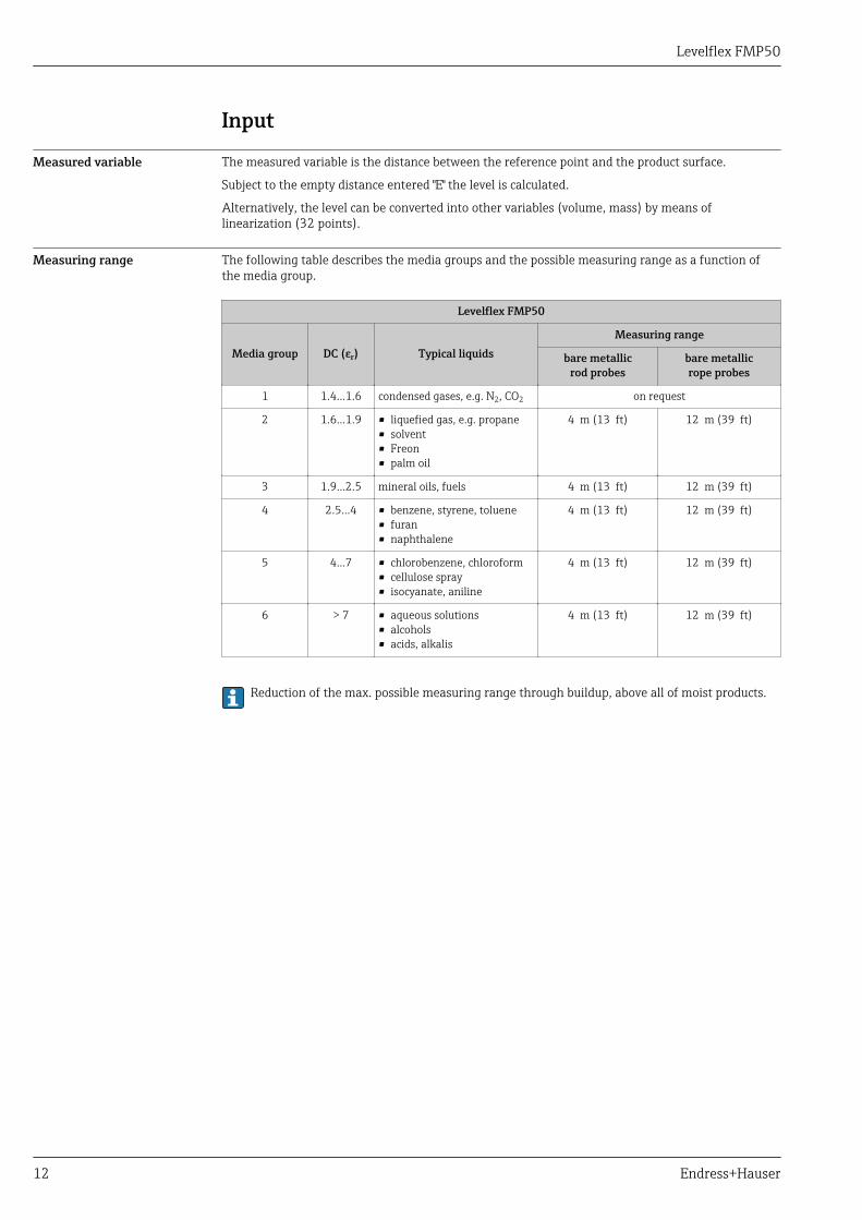
Measuring range The following table describes the media groups and the possible measuring range as a function ofthe media group.
Levelflex FMP50
Media group DC (εr) Typical liquidsMeasuring range
bare metallicrod probes
bare metallicrope probes
1 1.4...1.6 condensed gases, e.g. N2, CO2 on request
2 1.6...1.9 • liquefied gas, e.g. propane• solvent• Freon• palm oil
4 m (13 ft) 12 m (39 ft)
3 1.9...2.5 mineral oils, fuels 4 m (13 ft) 12 m (39 ft)
4 2.5...4 • benzene, styrene, toluene• furan• naphthalene
4 m (13 ft) 12 m (39 ft)
5 4...7 • chlorobenzene, chloroform• cellulose spray• isocyanate, aniline
4 m (13 ft) 12 m (39 ft)
6 > 7 • aqueous solutions• alcohols• acids, alkalis
4 m (13 ft) 12 m (39 ft)
Reduction of the max. possible measuring range through buildup, above all of moist products.
Levelflex FMP50
Endress+Hauser 13
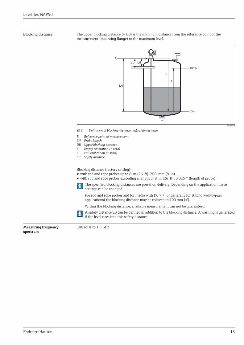
Blocking distance The upper blocking distance (= UB) is the minimum distance from the reference point of themeasurement (mounting flange) to the maximum level.
F
UB
E
100%
0%
LN
R
SD
A0011279
2 Definition of blocking distance and safety distance
R Reference point of measurementLN Probe lengthUB Upper blocking distanceE Empty calibration (= zero)F Full calibration (= span)SD Safety distance
Blocking distance (factory setting):• with rod and rope probes up to 8 m (26 ft): 200 mm (8 in)• with rod and rope probes exceeding a length of 8 m (26 ft): 0.025 * (length of probe)
The specified blocking distances are preset on delivery. Depending on the application thesesettings can be changed.
For rod and rope probes and for media with DC > 7 (or generally for stilling well/bypassapplications) the blocking distance may be reduced to 100 mm (4").
Within the blocking distance, a reliable measurement can not be guaranteed.A safety distance SD can be defined in addition to the blocking distance. A warning is generatedif the level rises into this safety distance.
Measuring frequencyspectrum
100 MHz to 1.5 GHz
Levelflex FMP50
14 Endress+Hauser
Output
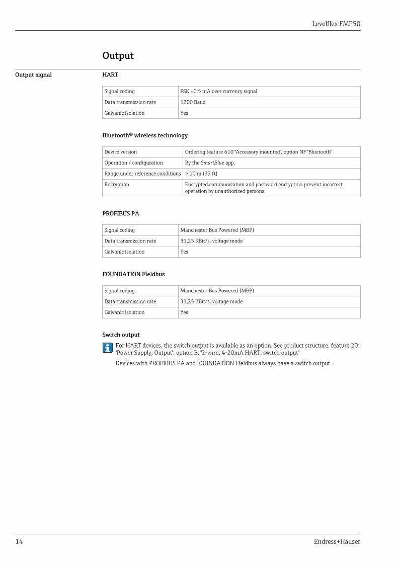
Output signal HART
Signal coding FSK ±0.5 mA over currency signal
Data transmission rate 1200 Baud
Galvanic isolation Yes
Bluetooth® wireless technology
Device version Ordering feature 610 "Accessory mounted", option NF "Bluetooth"
Operation / configuration By the SmartBlue app.
Range under reference conditions > 10 m (33 ft)
Encryption Encrypted communication and password encryption prevent incorrectoperation by unauthorized persons.
PROFIBUS PA
Signal coding Manchester Bus Powered (MBP)
Data transmission rate 31,25 KBit/s, voltage mode
Galvanic isolation Yes
FOUNDATION Fieldbus
Signal coding Manchester Bus Powered (MBP)
Data transmission rate 31,25 KBit/s, voltage mode
Galvanic isolation Yes
Switch output
For HART devices, the switch output is available as an option. See product structure, feature 20:"Power Supply, Output", option B: "2-wire; 4-20mA HART, switch output"
Devices with PROFIBUS PA and FOUNDATION Fieldbus always have a switch output.
Levelflex FMP50
Endress+Hauser 15
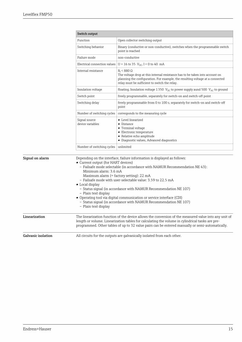
Switch output
Function Open collector switching output
Switching behavior Binary (conductive or non-conductive), switches when the programmable switchpoint is reached
Failure mode non-conductive
Electrical connection values U = 16 to 35 VDC, I = 0 to 40 mA
Internal resistance RI < 880 ΩThe voltage drop at this internal resistance has to be taken into account onplanning the configuration. For example, the resulting voltage at a connectedrelay must be sufficient to switch the relay.
Insulation voltage floating, Insulation voltage 1 350 VDC to power supply aund 500 VAC to ground
Switch point freely programmable, separately for switch-on and switch-off point
Switching delay freely programmable from 0 to 100 s, separately for switch-on and switch-offpoint
Number of switching cycles corresponds to the measuring cycle
Signal sourcedevice variables
• Level linearized• Distance• Terminal voltage• Electronic temperature• Relative echo amplitude• Diagnostic values, Advanced diagnostics
Number of switching cycles unlimited
Signal on alarm Depending on the interface, failure information is displayed as follows:• Current output (for HART devices)
– Failsafe mode selectable (in accordance with NAMUR Recommendation NE 43):Minimum alarm: 3.6 mAMaximum alarm (= factory setting): 22 mA
– Failsafe mode with user-selectable value: 3.59 to 22.5 mA• Local display
– Status signal (in accordance with NAMUR Recommendation NE 107)– Plain text display
• Operating tool via digital communication or service interface (CDI)– Status signal (in accordance with NAMUR Recommendation NE 107)– Plain text display
Linearization The linearization function of the device allows the conversion of the measured value into any unit oflength or volume. Linearization tables for calculating the volume in cylindrical tanks are pre-programmed. Other tables of up to 32 value pairs can be entered manually or semi-automatically.
Galvanic isolation All circuits for the outputs are galvanically isolated from each other.
Levelflex FMP50
16 Endress+Hauser
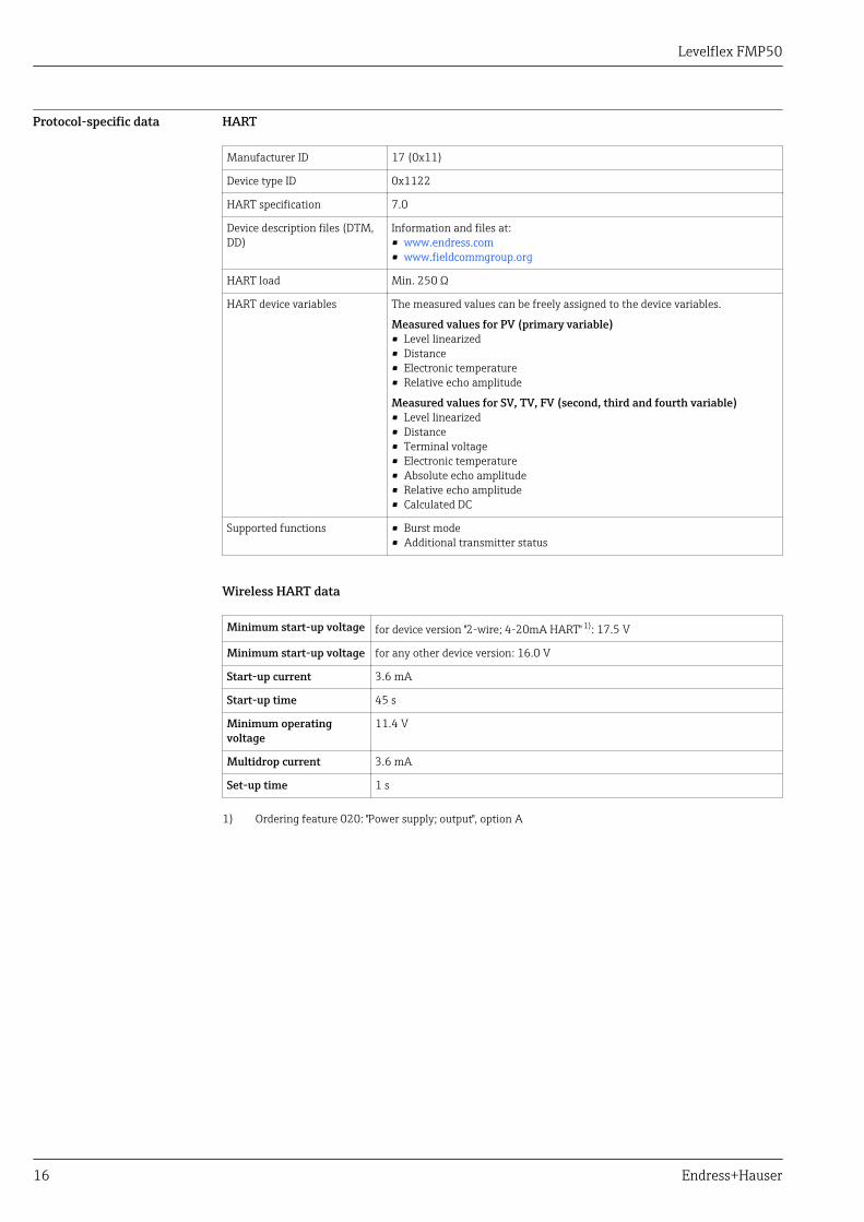
Protocol-specific data HART
Manufacturer ID 17 (0x11)
Device type ID 0x1122
HART specification 7.0
Device description files (DTM,DD)
Information and files at:• www.endress.com• www.fieldcommgroup.org
HART load Min. 250 Ω
HART device variables The measured values can be freely assigned to the device variables.
Measured values for PV (primary variable)• Level linearized• Distance• Electronic temperature• Relative echo amplitude
Measured values for SV, TV, FV (second, third and fourth variable)• Level linearized• Distance• Terminal voltage• Electronic temperature• Absolute echo amplitude• Relative echo amplitude• Calculated DC
Supported functions • Burst mode• Additional transmitter status
Wireless HART data
Minimum start-up voltage for device version "2-wire; 4-20mA HART" 1): 17.5 V
Minimum start-up voltage for any other device version: 16.0 V
Start-up current 3.6 mA
Start-up time 45 s
Minimum operatingvoltage
11.4 V
Multidrop current 3.6 mA
Set-up time 1 s
1) Ordering feature 020: "Power supply; output", option A
Levelflex FMP50
Endress+Hauser 17
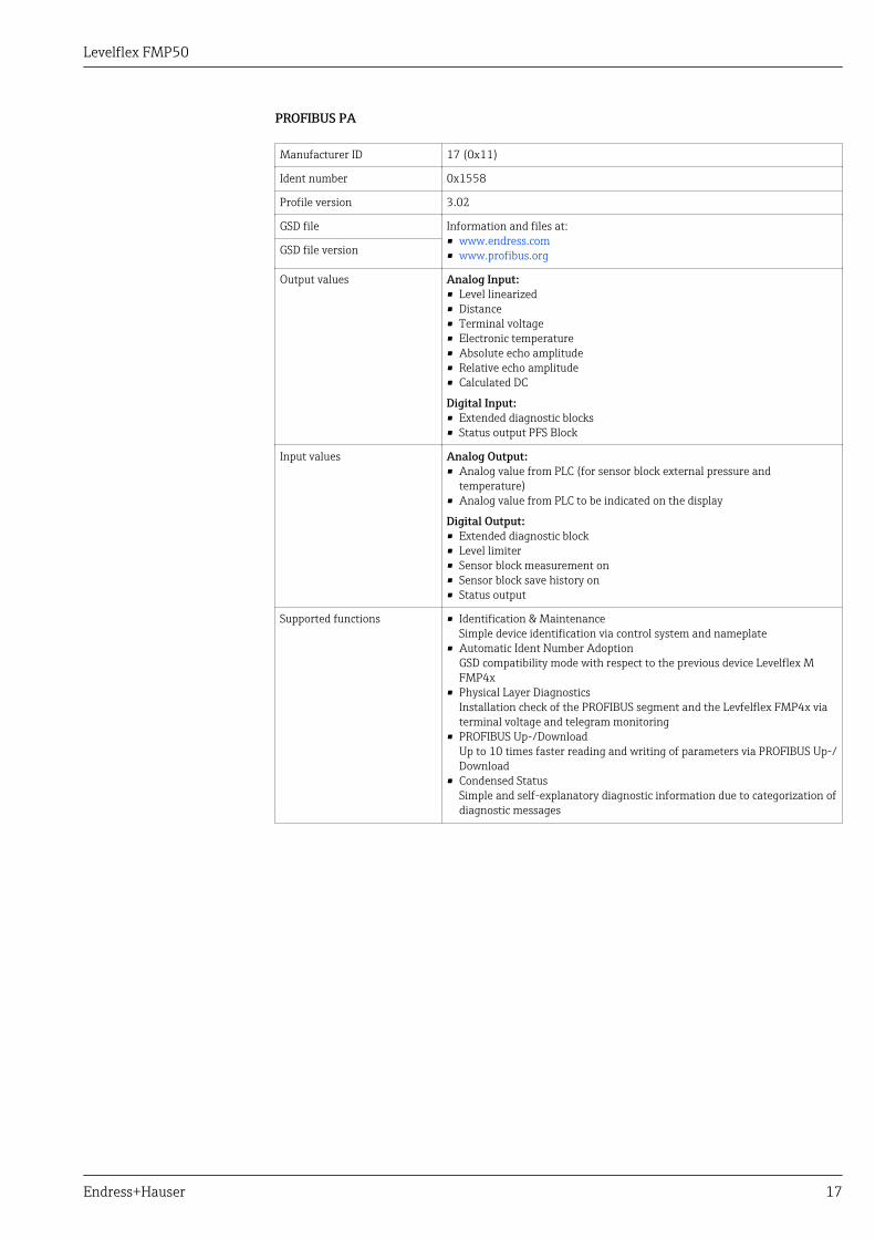
PROFIBUS PA
Manufacturer ID 17 (0x11)
Ident number 0x1558
Profile version 3.02
GSD file Information and files at:• www.endress.com• www.profibus.orgGSD file version
Output values Analog Input:• Level linearized• Distance• Terminal voltage• Electronic temperature• Absolute echo amplitude• Relative echo amplitude• Calculated DC
Digital Input:• Extended diagnostic blocks• Status output PFS Block
Input values Analog Output:• Analog value from PLC (for sensor block external pressure and
temperature)• Analog value from PLC to be indicated on the display
Digital Output:• Extended diagnostic block• Level limiter• Sensor block measurement on• Sensor block save history on• Status output
Supported functions • Identification & MaintenanceSimple device identification via control system and nameplate
• Automatic Ident Number AdoptionGSD compatibility mode with respect to the previous device Levelflex MFMP4x
• Physical Layer DiagnosticsInstallation check of the PROFIBUS segment and the Levfelflex FMP4x viaterminal voltage and telegram monitoring
• PROFIBUS Up-/DownloadUp to 10 times faster reading and writing of parameters via PROFIBUS Up-/Download
• Condensed StatusSimple and self-explanatory diagnostic information due to categorization ofdiagnostic messages
Levelflex FMP50
18 Endress+Hauser
FOUNDATION Fieldbus
Manufacturer ID 0x452B48
Device type 0x1022
Device Revision 0x01
DD Revision Information and files at:• www.endress.com• www.fieldcommgroup.orgCFF Revision
Device Tester Version (ITKVersion)
6.01
ITK Test Campaign Number IT080500
Link Master (LAS) capable yes
Link Master / Basic Deviceselectable
yes; default: Basic Device
Node address Default: 247 (0xF7)
Features supported Following methods are supported:• Restart• ENP Restart• Setup• Linearization• Self Check
Virtual Communication Relationships (VCRs)
Number of VCRs 44
Number of Link Objects in VFD 50
Permanent entries 1
Client VCRs 0
Server VCRs 10
Source VCRs 43
Sink VCRs 0
Subscriber VCRs 43
Publisher VCRs 43
Device Link Capabilities
Slot time 4
Min. inter PDU delay 8
Max. response delay 5
Levelflex FMP50
Endress+Hauser 19
Transducer Blocks
Block Content Output values
Setup Transducer Block Contains all parameters for a standard commissioningprocedure
• Level or volume 1)
(Channel 1)• Distance (Channel 2)
Advanced SetupTransducer Block
Contains all parameters for a more detailedconfiguration of the device
no output values
Display Transducer Block Contains all parameters for the configuration of thedisplay module
no output values
Diagnostic TransducerBlock
Contains diagnostic information no output values
Expert ConfigurationTransducer Block
Contains parameters which require detailedknowledge of the functionalities of the device
no output values
Expert InformationTransducer Block
Contains information about the state of the device no output values
Service Sensor TransducerBlock
Contains parameters which can only be operated byEndress+Hauser service personnel
no output values
Service InformationTransducer Block
Contains information on the state of device which isrelevant for service operations
no output values
Data Transfer TransducerBlock
Contains parameters which allow to backup the deviceconfiguration in the display module and to restore itinto the device.
no output values
1) depending on the configuration of the block
Levelflex FMP50
20 Endress+Hauser
Function Blocks
Block Content Number ofpermanentblocks
Number ofinstantiableblocks
Executiontime
Functionality
Resource Block The Resource Block contains all thedata that uniquely identify the fielddevice. It is an electronic version ofa nameplate of the device.
1 0 - enhanced
Analog InputBlock
The AI block takes themanufacturer's input data, selectedby channel number, and makes itavailable to other function blocks atits output.
2 3 25 ms enhanced
Discrete InputBlock
The DI block takes a discrete inputvalue (e.g. indication of an levellimit), and makes it available toother function blocks at its output.
1 2 20 ms standard
PID Block The PID block serves asproportional-integral-derivativecontroller and is used almostuniversally to do closed-loop-control in the field includingcascade and feedforward.
1 1 25 ms standard
ArithmeticBlock
This block is designed to permitsimple use of popular measurementmath functions. The user does nothave to know how to writeequations. The math algorithm isselected by name, chosen by theuser for the function to be done.
1 1 25 ms standard
SignalCharacterizerBlock
The signal characterizer block hastwo sections, each with an outputthat is a non-linear function of therespective input. The non-linearfunction is determined by a singlelook-up table with 21 arbitrary x-ypairs.
1 1 25 ms standard
Input SelectorBlock
The input selector block providesselection of up to four inputs andgenerates an output based on theconfigured action. This blocknormally receives its inputs from AIblocks. The block performsmaximum, minimum, middle,average and ‘first good’ signalselection.
1 1 25 ms standard
IntegratorBlock
The Integrator Function Blockintegrates a variable as a functionof the time or accumulates thecounts from a Pulse Input block.The block may be used as atotalizer that counts up until resetor as a batch totalizer that has asetpoint, where the integrated oraccumulated value is compared topre-trip and trip settings,generating discrete signals whenthese settings are reached.
1 1 25 ms standard
Analog AlarmBlock
1 1 25 ms standard
Up to 20 blocks can be instantiated in the device altogether, including the blocks alreadyinstantiated on delivery.
Levelflex FMP50
Endress+Hauser 21
Power supply
Terminal assignmentTerminal assignment 2-wire: 4-20 mA HART
1
+2
-
A
1
+
2
-
B
1
2
3
A0036498
3 Terminal assignment 2-wire: 4-20 mA HART
A Without integrated overvoltage protectionB With integrated overvoltage protection1 Connection 4-20 mA HART passive: terminals 1 and 2, without integrated overvoltage protection2 Connection 4-20 mA HART passive: terminals 1 and 2, with integrated overvoltage protection3 Terminal for cable screen
Block diagram 2-wire: 4-20 mA HART
5
4
1
2
3
++
--
Y
I
6
1
2
A0036499
4 Block diagram 2-wire: 4-20 mA HART
1 Active barrier with power supply (e.g. RN221N); observe terminal voltage2 HART communication resistor (≥ 250 Ω); observe maximum load3 Connection for Commubox FXA195 or FieldXpert SFX350/SFX370 (via VIATOR Bluetooth modem)4 Analog display device; observe maximum load5 Cable screen; observe cable specification6 Measuring device

Levelflex FMP50
22 Endress+Hauser
Terminal assignment 2-wire: 4-20 mA HART, switch output
1
3
+
+
2
4
-
-
A
1
3
+
+
2
4
-
-
B
1
4
5
2
3
A0036500
5 Terminal assignment 2-wire: 4-20 mA HART, switch output
A Without integrated overvoltage protectionB With integrated overvoltage protection1 Connection 4-20 mA HART passive: terminals 1 and 2, without integrated overvoltage protection2 Connection switch output (Open Collector): terminals 3 and 4, without integrated overvoltage protection3 Connection switch output (Open Collector): terminals 3 and 4, with integrated overvoltage protection4 Connection 4-20 mA HART passive: terminals 1 and 2, with integrated overvoltage protection5 Terminal for cable screen
Block diagram 2-wire: 4-20 mA HART, switch output
5
4
1
2
3
+
+
+
-
-
-
Y
I
6
7
1
2
3
4
A0036501
6 Block diagram 2-wire: 4-20 mA HART, switch output
1 Active barrier with power supply (e.g. RN221N); observe terminal voltage2 HART communication resistor (≥ 250 Ω); observe maximum load3 Connection for Commubox FXA195 or FieldXpert SFX350/SFX370 (via VIATOR Bluetooth modem)4 Analog display device; observe maximum load5 Cable screen; observe cable specification6 Measuring device7 Switch output (Open Collector)
Levelflex FMP50
Endress+Hauser 23
Terminal assignment 2-wire: 4-20 mA HART, 4-20 mA
1
3
+
+
2
4
-
-
A
1
3
+
+
2
4
-
-
B
1
4
5
2
3
A0036500
7 Terminal assignment 2-wire: 4-20 mA HART, 4-20 mA
A Without integrated overvoltage protectionB With integrated overvoltage protection1 Connection current output 1, 4-20 mA HART passive: terminals 1 and 2, without integrated overvoltage
protection2 Connection current output 2, 4-20 mA: terminals 3 and 4, without integrated overvoltage protection3 Connection current output 2, 4-20 mA: terminals 3 and 4, with integrated overvoltage protection4 Connection current output 1, 4-20 mA HART passive: terminals 1 and 2, with integrated overvoltage
protection5 Terminal for cable screen
Block diagram 2-wire: 4-20 mA HART, 4-20 mA
5
4
1
2
3
+
++
+
-
--
-
Y
I
6
7
8
1
2
3
4
A0036502
8 Block diagram 2-wire: 4-20 mA HART, 4-20 mA
1 Active barrier with power supply (e.g. RN221N); observe terminal voltage2 HART communication resistor (≥ 250 Ω); observe maximum load3 Connection for Commubox FXA195 or FieldXpert SFX350/SFX370 (via VIATOR Bluetooth modem)4 Analog display device; observe maximum load5 Cable screen; observe cable specification6 Measuring device7 Analog display device; observe maximum load8 Active barrier with power supply (e.g. RN221N), current output 2; observe terminal voltage
Levelflex FMP50
24 Endress+Hauser
Terminal assignment 4-wire: 4-20 mA HART (10.4 to 48 VDC)
3
1
+
L+
4
2
-
L-
1
32
A0036516
9 Terminal assignment 4-wire: 4-20 mA HART (10.4 to 48 VDC)
1 Connection 4-20 mA HART (active): terminals 3 and 42 Connection supply voltage: terminals 1 and 23 Terminal for cable screen
Block diagram 4-wire: 4-20 mA HART (10.4 to 48 VDC)
5
4
1
2
3
+
L+
-
L- Y
I
6
7
3
4
1
2
A0036526
10 Block diagram 4-wire: 4-20 mA HART (10.4 to 48 VDC)
1 Evaluation unit, e.g. PLC2 HART communication resistor (≥ 250 Ω); observe maximum load3 Connection for Commubox FXA195 or FieldXpert SFX350/SFX370 (via VIATOR Bluetooth modem)4 Analog display device; observe maximum load5 Cable screen; observe cable specification6 Measuring device7 Supply voltage; observe terminal voltage, observe cable specification
Levelflex FMP50
Endress+Hauser 25
Terminal assignment 4-wire: 4-20 mA HART (90 to 253 VAC)
3
1
+
L
4
2
-
N
1
32
A0036519
11 Terminal assignment 4-wire: 4-20 mA HART (90 to 253 VAC)
1 Connection 4-20 mA HART (active): terminals 3 and 42 Connection supply voltage: terminals 1 and 23 Terminal for cable screen
LCAUTIONTo ensure electrical safety:‣ Do not disconnect the protective connection.‣ Disconnect the supply voltage before disconnecting the protective earth.
Connect protective earth to the internal ground terminal (3) before connecting the supplyvoltage. If necessary, connect the potential matching line to the external ground terminal.In order to ensure electromagnetic compatibility (EMC): Do not only ground the device via theprotective earth conductor of the supply cable. Instead, the functional grounding must also beconnected to the process connection (flange or threaded connection) or to the external groundterminal.An easily accessible power switch must be installed in the proximity of the device. The powerswitch must be marked as a disconnector for the device (IEC/EN61010).
Levelflex FMP50
26 Endress+Hauser
Block diagram 4-wire: 4-20 mA HART (90 to 253 VAC)
5
4
1
2
3
+
L
-
NY
I
6
7
3
4
1
2
A0036527
12 Block diagram 4-wire: 4-20 mA HART (90 to 253 VAC)
1 Evaluation unit, e.g. PLC2 HART communication resistor (≥ 250 Ω); observe maximum load3 Connection for Commubox FXA195 or FieldXpert SFX350/SFX370 (via VIATOR Bluetooth modem)4 Analog display device; observe maximum load5 Cable scree; observe cable specification6 Measuring device7 Supply voltage; observe terminal voltage, observe cable specification
Terminal assignment PROFIBUS PA / FOUNDATION Fieldbus
1
3
+
+
2
4
-
-
A
1
3
+
+
2
4
-
-
B
1
4
5
2
3
A0036500
13 Terminal assignment PROFIBUS PA / FOUNDATION Fieldbus
A Without integrated overvoltage protectionB With integrated overvoltage protection1 Connection PROFIBUS PA / FOUNDATION Fieldbus: terminals 1 and 2, without integrated overvoltage
protection2 Connection switch output (Open Collector): terminals 3 and 4, without integrated overvoltage protection3 Connection switch output (Open Collector): terminals 3 and 4, with integrated overvoltage protection4 Connection PROFIBUS PA / FOUNDATION Fieldbus: terminals 1 and 2, with integrated overvoltage protection5 Terminal for cable screen
Levelflex FMP50
Endress+Hauser 27
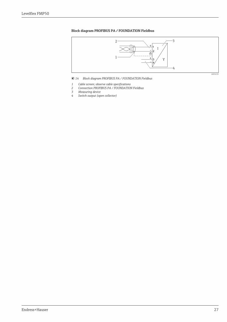
Block diagram PROFIBUS PA / FOUNDATION Fieldbus
+
+
-
-Y
I
2 3
1
2
3
4
1
4
A0036530
14 Block diagram PROFIBUS PA / FOUNDATION Fieldbus
1 Cable screen; observe cable specifications2 Connection PROFIBUS PA / FOUNDATION Fieldbus3 Measuring device4 Switch output (open collector)
Levelflex FMP50
28 Endress+Hauser
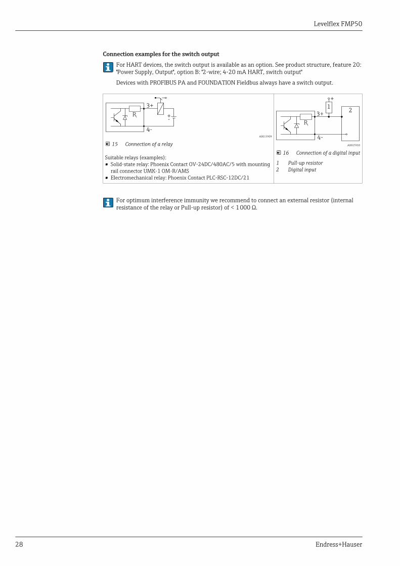
Connection examples for the switch output
For HART devices, the switch output is available as an option. See product structure, feature 20:"Power Supply, Output", option B: "2-wire; 4-20 mA HART, switch output"
Devices with PROFIBUS PA and FOUNDATION Fieldbus always have a switch output.
3+
+-
4-
Ri
A0015909
15 Connection of a relay
Suitable relays (examples):• Solid-state relay: Phoenix Contact OV-24DC/480AC/5 with mounting
rail connector UMK-1 OM-R/AMS• Electromechanical relay: Phoenix Contact PLC-RSC-12DC/21
3+2
1
+
4-
Ri
A0015910
16 Connection of a digital input
1 Pull-up resistor2 Digital input
For optimum interference immunity we recommend to connect an external resistor (internalresistance of the relay or Pull-up resistor) of < 1 000 Ω.
Levelflex FMP50
Endress+Hauser 29
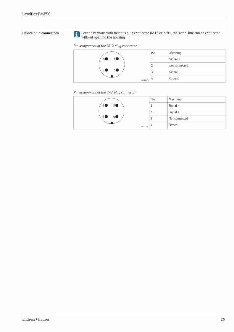
Device plug connectors For the versions with fieldbus plug connector (M12 or 7/8"), the signal line can be connectedwithout opening the housing.
Pin assignment of the M12 plug connector
21
34
A0011175
Pin Meaning
1 Signal +
2 not connected
3 Signal -
4 Ground
Pin assignment of the 7/8" plug connector
42
31
A0011176
Pin Meaning
1 Signal -
2 Signal +
3 Not connected
4 Screen
Levelflex FMP50
30 Endress+Hauser
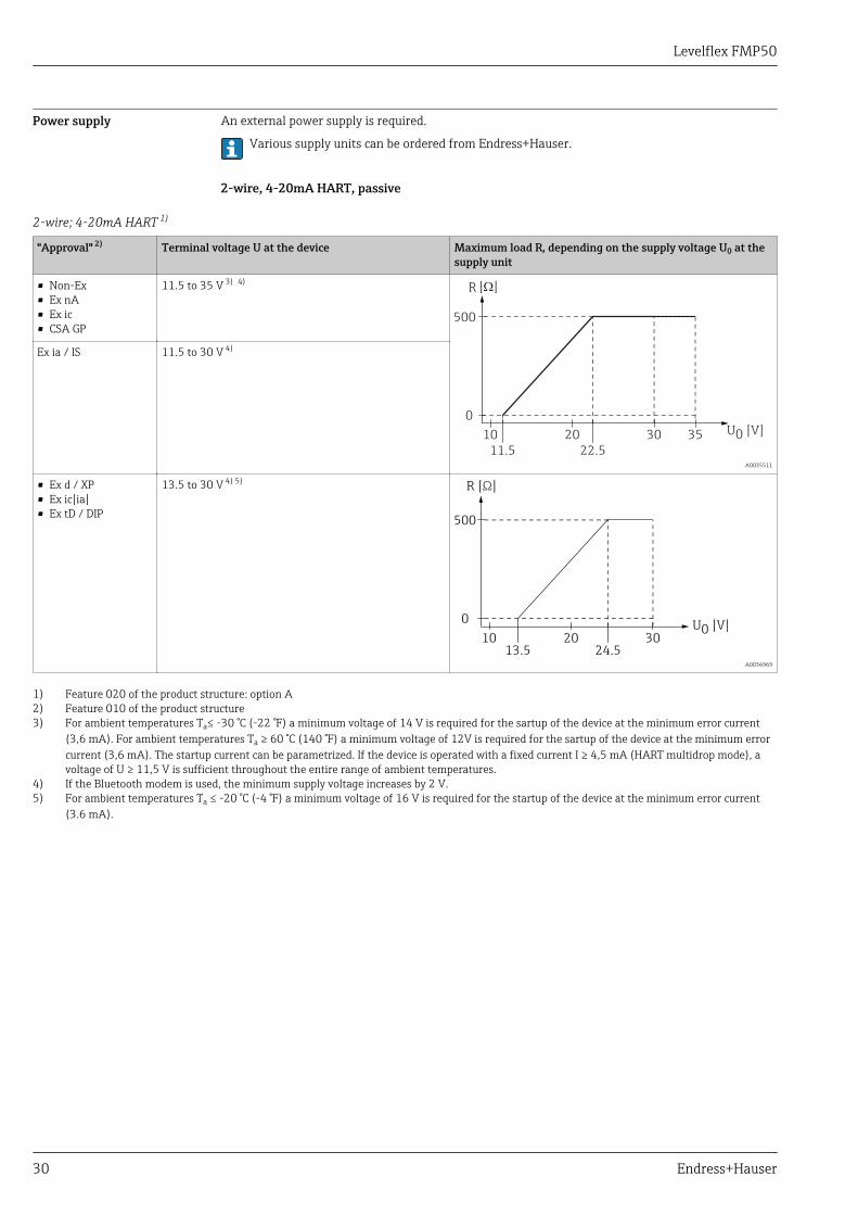
Power supply An external power supply is required.
Various supply units can be ordered from Endress+Hauser.
2-wire, 4-20mA HART, passive
2-wire; 4-20mA HART 1)
"Approval" 2) Terminal voltage U at the device Maximum load R, depending on the supply voltage U0 at thesupply unit
• Non-Ex• Ex nA• Ex ic• CSA GP
11.5 to 35 V 3) 4)
U0 [V]10
11.5 22.5
20 30 35
0
500
R [ ]W
A0035511
Ex ia / IS 11.5 to 30 V 4)
• Ex d / XP• Ex ic[ia]• Ex tD / DIP
13.5 to 30 V 4) 5)R [ ]Ω
[V]U010
13.5 24.520 30
0
500
A0034969
1) Feature 020 of the product structure: option A2) Feature 010 of the product structure3) For ambient temperatures Ta≤ -30 °C (-22 °F) a minimum voltage of 14 V is required for the sartup of the device at the minimum error current
(3,6 mA). For ambient temperatures Ta ≥ 60 °C (140 °F) a minimum voltage of 12V is required for the sartup of the device at the minimum errorcurrent (3,6 mA). The startup current can be parametrized. If the device is operated with a fixed current I ≥ 4,5 mA (HART multidrop mode), avoltage of U ≥ 11,5 V is sufficient throughout the entire range of ambient temperatures.
4) If the Bluetooth modem is used, the minimum supply voltage increases by 2 V.5) For ambient temperatures Ta ≤ -20 °C (-4 °F) a minimum voltage of 16 V is required for the startup of the device at the minimum error current
(3.6 mA).
Levelflex FMP50
Endress+Hauser 31
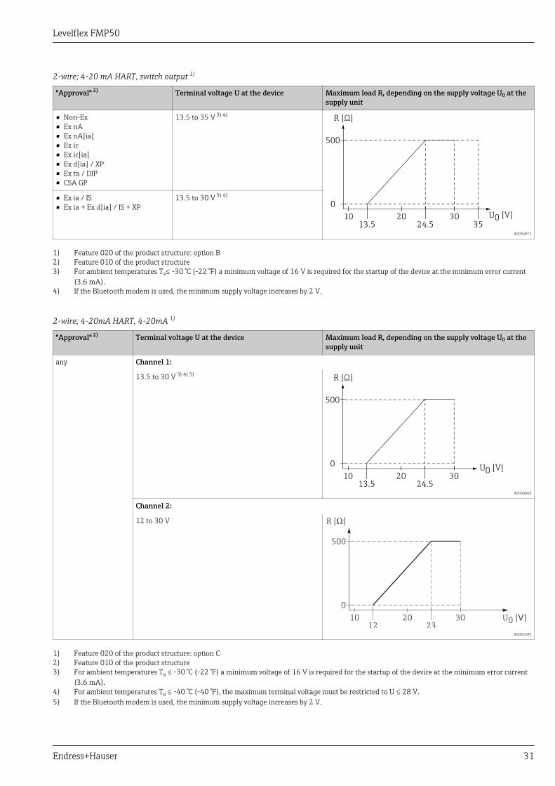
2-wire; 4-20 mA HART, switch output 1)
"Approval" 2) Terminal voltage U at the device Maximum load R, depending on the supply voltage U0 at thesupply unit
• Non-Ex• Ex nA• Ex nA[ia]• Ex ic• Ex ic[ia]• Ex d[ia] / XP• Ex ta / DIP• CSA GP
13.5 to 35 V 3) 4)R [ ]Ω
[V]U01013.5 24.5
20 30
0
500
35 A0034971
• Ex ia / IS• Ex ia + Ex d[ia] / IS + XP
13.5 to 30 V 3) 4)
1) Feature 020 of the product structure: option B2) Feature 010 of the product structure3) For ambient temperatures Ta≤ -30 °C (-22 °F) a minimum voltage of 16 V is required for the startup of the device at the minimum error current
(3.6 mA).4) If the Bluetooth modem is used, the minimum supply voltage increases by 2 V.
2-wire; 4-20mA HART, 4-20mA 1)
"Approval" 2) Terminal voltage U at the device Maximum load R, depending on the supply voltage U0 at thesupply unit
any Channel 1:
13.5 to 30 V 3) 4) 5)R [ ]Ω
[V]U010
13.5 24.520 30
0
500
A0034969
Channel 2:
12 to 30 V R [ ]W
VU0 [ ]1012 23
20 30
0
500
A0022583
1) Feature 020 of the product structure: option C2) Feature 010 of the product structure3) For ambient temperatures Ta ≤ -30 °C (-22 °F) a minimum voltage of 16 V is required for the startup of the device at the minimum error current
(3.6 mA).4) For ambient temperatures Ta ≤ -40 °C (-40 °F), the maximum terminal voltage must be restricted to U ≤ 28 V.5) If the Bluetooth modem is used, the minimum supply voltage increases by 2 V.

Levelflex FMP50
32 Endress+Hauser
Polarity reversalprotection
Yes
Admissible residual rippleat f = 0 to 100 Hz
USS < 1 V
Admissible residual rippleat f = 100 to 10000 Hz
USS < 10 mV
Levelflex FMP50
Endress+Hauser 33
4-wire, 4-20mA HART, active
"Power supply; Output" 1) Terminal voltage Maximum load Rmax
K: 4-wire 90-253VAC; 4-20mA HART 90 to 253 VAC (50 to 60 Hz), overvoltagecategory II
500 Ω
L: 4-wire 10,4-48VDC; 4-20mA HART 10.4 to 48 VDC
1) Feature 020 of the product structure
PROFIBUS PA, FOUNDATION Fieldbus
"Power supply; Output" 1) "Approval" 2) Terminal voltage
E: 2-wire; FOUNDATION Fieldbus, switch outputG: 2-wire; PROFIBUS PA, switch output
• Non-Ex• Ex nA• Ex nA[ia]• Ex ic• Ex ic[ia]• Ex d[ia] / XP• Ex ta / DIP• CSA GP
9 to 32 V 3)
• Ex ia / IS• Ex ia + Ex d[ia] / IS + XP
9 to 30 V 3)
1) Feature 020 of the product structure2) Feature 010 of the product structure3) Input voltages up to 35 V will not spoil the device.
Polarity sensitive No
FISCO/FNICO compliantaccording to IEC 60079-27
Yes
Power consumption "Power supply; Output" 1) Power consumption
A: 2-wire; 4-20mA HART < 0.9 W
B: 2-wire; 4-20mA HART, switch output < 0.9 W
C: 2-wire; 4-20mA HART, 4-20mA < 2 x 0.7 W
K: 4-wire 90-253VAC; 4-20mA HART 6 VA
L: 4-wire 10,4-48VDC; 4-20mA HART 1.3 W
1) Feature 020 of the product structure
Current consumption HART
Nominal current 3.6 to 22 mA, the start-up current for multidrop mode can be parametrized (isset to 3.6 mA on delivery)
Breakdown signal(NAMUR NE43)
adjustable: 3.59 to 22.5 mA
PROFIBUS PA
Nominal current 14 mA
Failure current FDE (FaultDisconnection Electronic)
0 mA
Levelflex FMP50
34 Endress+Hauser
FOUNDATION Fieldbus
Device basic current 15 mA
Failure current FDE (FaultDisconnection Electronic)
0 mA
FISCO
Ui 17.5 V
Ii 550 mA
Pi 5.5 W
Ci 5 nF
Li 10 μH
Power supply failure • Configuration is retained in the HistoROM (EEPROM).• Error messages (incl. value of operated hours counter) are stored.
Potential equalization No special measures for potential equalization are required.
If the device is designed for hazardous areas, observe the information in the documentation"Safety Instructions" (XA).
Terminals • Without integrated overvoltage protectionPlug-in spring terminals for wire cross-sections 0.5 to 2.5 mm2 (20 to 14 AWG)
• With integrated overvoltage protectionScrew terminals for wire cross-sections 0.2 to 2.5 mm2 (24 to 14 AWG)
Cable entries Connection of power supply and signal line
To be selected in feature 050 "Electrical connection"• Gland M20; Material dependent on the approval:
– For Non-Ex, ATEX, IECEx, NEPSI Ex ia/ic:Plastics M20x1.5 for cable 5 to 10 mm (0.2 to 0.39 in)
– For Dust-Ex, FM IS, CSA IS, CSA GP, Ex nA:– For Ex d:
No gland available• Thread
– ½" NPT– G ½"– M20 × 1.5
• Plug M12 / Plug 7/8"Only available for Non-Ex, Ex ic, Ex ia
Connection of remote display FHX50
Feature 030 "Display, Operation" Cable entry for FHX50 connection
L: "Prepared for display FHX50 + M12 connection" M12 socket
M: "Prepared for display FHX50 + M16 gland, custom connection" M12 cable gland
N: "Prepared for display FHX50 + NPT1/2 thread, custom connection" NPT1/2 thread
Cable specification • Devices without integrated overvoltage protectionPluggable spring-force terminals for wire cross-sections 0.5 to 2.5 mm2 (20 to 14 AWG)
• Devices with integrated overvoltage protectionScrew terminals for wire cross-sections 0.2 to 2.5 mm2 (24 to 14 AWG)
• For ambient temperature TU≥60 °C (140 °F): use cable for temperature TU +20 K.
Levelflex FMP50
Endress+Hauser 35
HART
• A normal device cable suffices if only the analog signal is used.• A shielded cable is recommended if using the HART protocol. Observe grounding concept of the
plant.• For 4-wire devices: Standard device cable is sufficient for the power line.
PROFIBUS
Use a twisted, screened two-wire cable, preferably cable type A.For further information on the cable specifications, see Operating Instructions BA00034S"PROFIBUS DP/PA: Guidelines for planning and commissioning", PNO Guideline 2.092"PROFIBUS PA User and Installation Guideline" and IEC 61158-2 (MBP).
FOUNDATION Fieldbus
Endress+Hauser recommends using twisted, shielded two-wire cables.For further information on the cable specifications, see Operating Instructions BA00013S"FOUNDATION Fieldbus Overview", FOUNDATION Fieldbus Guideline and IEC 61158-2 (MBP).
Overvoltage protection If the measuring device is used for level measurement in flammable liquids which requires the use ofovervoltage protection according to DIN EN 60079-14, standard fortest procedures 60060-1 (10 kA, pulse 8/20 μs), an overvoltage protection module has to beinstalled.
Integrated overvoltage protection module
An integrated overvoltage protection module is available for 2-wire HART as well as PROFIBUS PAand FOUNDATION Fieldbus devices.
Product structure: Feature 610 "Accessory mounted", option NA "Overvoltage protection".
Technical data
Resistance per channel 2 × 0.5 Ω max.
Threshold DC voltage 400 to 700 V
Threshold impulse voltage < 800 V
Capacitance at 1 MHz < 1.5 pF
Nominal arrest impulse voltage (8/20 μs) 10 kA
External overvoltage protection module
HAW562 or HAW569 from Endress+Hauser are suited as external overvoltage protection.
For detailed information please refer to the following documents:• HAW562: TI01012K• HAW569: TI01013K
Levelflex FMP50
36 Endress+Hauser
Performance characteristics
Reference operatingconditions
• Temperature = +24 °C (+75 °F) ±5 °C (±9 °F)• Pressure = 960 mbar abs. (14 psia) ±100 mbar (±1.45 psi)• Humidity = 60 % ±15 %• Reflection factor ≥ 0,8 (metal plate for rod and rope probe with min. 1 m (40 in) diameter)• Flange for rod or rope probe ≥ 300 mm (12 in) diameter• Distance to obstacles ≥ 1 m (40 in)
Reference accuracy Typical data under reference operating conditions: DIN EN IEC 61298-2 / DIN EN IEC 60770-1,percentage values in relation to the span.
Output: digital analog 1)
Accuracy (Sum of non-linearity, nonrepeatabilityand hysteresis) 2)
±2 mm (±0.08 in) ±0.02 %
Non-repeatability 3) ≤ 1 mm (0.04 in)
1) Add error of the analogous value to the digital value.2) If the reference conditions are not met, the offset/zero point arising from the mounting conditions may be
up to ±16 mm (±0.63 in). This additional offset/zero point can be compensated for by entering acorrection (parameter "level correction") during commissioning.
3) The non-repeatability is already considered in the accuracy.
Differing from this, the following measuring error is present in the vicinity of the lower probeend:
-80 (-3.15)
-60 (-2.36)
-40 (-1.57)
-20 (-0.79)
0
20 (0.79)
40 (1.57)
60 (2.36)
80 (3.15)
0 A
D
DC = 2
DC = 80
50
(1
.97
)
10
0 (
3.9
4)
15
0 (
5.9
1)
20
0 (
7.8
7)
40
(1
.57
)
80
(3
.15
)
20
(0
.79
)
25
0 (
9.8
4)
30
0 (
11
.8)
A0021480
17 Measuring error at the end-of-probe for rod and coax probes
A Distance from probe end [mm(in)]D Measuring error: Sum of non-linearity, non-repeatability and hysteresis

Levelflex FMP50
Endress+Hauser 37
-80 (-3.15)
-60 (-2.36)
-40 (-1.57)
-20 (-0.79)
0
20 (0.79)
40 (1.57)
60 (2.36)
80 (3.15)
0
DC = 80
A
D
50
(1
.97
)
10
0 (
3.9
4)
15
0 (
5.9
1)
20
0 (
7.8
7)
20
(0
.79
)
25
0 (
9.8
4)
30
0 (
11
.8)
A0021482
18 Measuring error at the end-of-probe for rope probes
A Distance from probe endD Measuring error: Sum of non-linearity, non-repeatability and hysteresis
If for rope probes the DC value is less than 7, then measurement is not possible in the area ofthe straining weight (0 to 250 mm from end of probe; lower blocking distance).
In the area of the upper probe end, the measuring error is as follows (rod/rope only):
2 (0.08)
0 (0)
- 2 (- 0.08)
100 (3.94) 200 (7.87)
10 (0.39)
- 10 (-0.39)
30 (1.18)
- 30 (- 1.18)
40 (1.57)
- 40 (- 1.57)
R
D
DC = 2
DC = 80
A0015091
19 Measuring error at the upper end of the probe; dimensions: mm (in)
D Sum of non-linearity, non-repeatability and hysteresisR Reference point of measurementDC Dielectric constant
Resolution • digital: 1 mm• analog: 1 μA

Levelflex FMP50
38 Endress+Hauser
Reaction time The reaction time can be parametrized. The following step response times (as per DIN EN IEC61298-2 / DIN EN IEC 60770-1) 2) are valid if the damping is switched off:
Level measurement
Probe length Sampling rate Step response time
< 12 m (39 ft) 3.6 measurements/second < 0.8 s
Influence of ambienttemperature
The measurements are carried out in accordance with DIN EN IEC 61298-3 / DIN EN IEC60770-1• digital (HART, PROFIBUS PA, FOUNDATION Fieldbus): average TK = 0.6 mm/10 K
For devices with remote sensor 3) there is an additional offset of ±0.3 mm/10K (±0.01 in/10K) per1 m (3.3 ft) of the remote cable.
• analog (current output):– zero point (4 mA): average TK = 0.02 %/10 K– span (20 mA): average TK = 0.05 %/10 K
2) According to DIN EN IEC 61298-2 / DIN EN IEC 60770-1 the response time is the time which passes after a sudden change of the input signaluntil the output signal for the first time assumes 90% of the steady-state value.
3) Product structure: Feature 600, options MB, MC or MD)
Levelflex FMP50
Endress+Hauser 39
Mounting
Mounting requirements Suitable mounting position
A
C
1 2 3
4
B
A0012606
20 Mounting requirements for Levelflex
Mounting distances
• Distance (A) between wall and rod or rope probe:– for smooth metallic walls: > 50 mm (2 in)– for plastic walls: > 300 mm (12 in) to metallic parts outside the vessel– for concrete walls: > 500 mm (20 in), otherwise the available measuring range may be reduced.
• Distance (B) between rod or rope probe and internal fittings in the vessel: > 300 mm (12 in)• When using more than one Levelflex:
Minimum distance between the sensor axes: 100 mm (3.94 in)• Distance (C) from end of probe to bottom of the vessel:
– Rope probe: > 150 mm (6 in)– Rod probe: > 10 mm (0.4 in)
Levelflex FMP50
40 Endress+Hauser
Additional conditions
• When mounting in the open, a weather protection cover (1) may be installed to protect the deviceagainst extreme weather conditions.
• In metallic vessels: Preferably do not mount the probe in the center of the vessel (2), as this wouldlead to increased interference echoes.If a central mounting position can not be avoided, it is crucial to perform an interference echosuppresion(mapping) after the commissioning of the device.
• Do not mount the probe in the filling curtain (3).• Avoid buckling the rope probe during installation or operation (e.g. through product movement
against silo wall) by selecting a suitable mounting location.With suspended rope probes (probe end not fixed at the bottom) the distance between theprobe rope and internal fittings in the tank must not fall below 300 mm (12") during the entireprocess. A sporadic contact between the probe weight and the cone of the vessel, however, doesnot influence the measurement as long as the dielectric constant of the medium is at least DC =1.8.When mounting the electronics housing into a recess (e.g. in a concrete ceiling), observe aminimum distance of 100 mm (4 inch) between the cover of the terminal compartment /electronics compartment and the wall. Otherwise the connection compartment / electronicscompartment is not accessible after installation.
Levelflex FMP50
Endress+Hauser 41
Applications with restricted mounting space
Mounting with remote sensor
The device version with a remote sensor is suited for applications with restricted mounting space. Inthis case the electronics housing is mounted at a separate position from which it is easier accessible.
A B
C Cr = 100 (4)min
r = 100 (4)min
6 Nm(4.42 lbf ft)
6 Nm(4.42 lbf ft)
6 Nm(4.42 lbf ft)
6 Nm(4.42 lbf ft)
A0014794
A Angled plug at the probeB Angled plug at the electronics housingC Length of the remote cable as ordered
• Product structure, feature 600 "Probe Design":– Option MB "Sensor remote, 3m/9ft cable"– Option MC "Sensor remote, 6m/18ft cable"– Option MB "Sensor remote, 9m/27ft cable"
• The remote cable is supplied with these device versionsMinimum bending radius: 100 mm (4 inch)
• A mounting bracket for the electronics housing is supplied with these device versions. Mountingoptions:– Wall mounting– Pipe mounting; diameter: 42 to 60 mm (1-1/4 to 2 inch)
• The connection cable has got one straight and one angled plug (90°). Depending on the localconditions the angled plug can be connected at the probe or at the electronics housing.
Probe, electronics and connection cable are adjusted to match each other. They are marked by acommon serial number. Only components with the same serial number shall be connected toeach other.
Levelflex FMP50
42 Endress+Hauser
Notes on the mechanical load of the probe
Tensile load limit of rope probes
Sensor Feature 060 Probe Tensile load limit [kN]
FMP50 LA, LB Rope 4mm (1/6") 316 2
Bending strength of rod probes
Sensor Feature 060 Probe Bending strength [Nm]
FMP50 AA, AB Rod 8mm (1/3") 316L 10
Bending load (torque) through fluid flow
The formula for calculating the bending torque M impacting on the probe:
M = cw ⋅ ρ/2 ⋅ v2 ⋅ d ⋅ L ⋅ (LN - 0.5 ⋅ L)
with:
cw: Friction factor
ρ [kg/m3]: Density of the medium
v [m/s]: Velocity of the medium perpendicular to the probe rod
d [m]: Diameter of the probe rod
L [m]: Level
LN [m]: Probe length
Calculation example
v
LN
L
d
A0014175
Friction factor cw 0,9 (on the assumption of a turbulent current - highReynolds number)
Density ρ [kg/m3] 1000 (e.g. water)
Probe diameter d [m] 0,008
L = LN (worst case)
Bending torque [M] on rod probes, diameter 8mm (1/3”)
Probe length [ ] in metersLN
v=0.5m/s
v=0.7m/s
v=1.0m/s
ma
x.
be
nd
ing
torq
ue
0.4 0.8 1.2 1.6 2 2.4 2.8 3.2 3.6 4
0.0
2.0
4.0
6.0
8.0
10.0
12.0
14.0
16.0
18.0
20.0
Be
nd
ing
[Nm
]to
rque
A0014182-EN
Levelflex FMP50
Endress+Hauser 43
Notes on the process connection
Probes are mounted to the process connection with threaded connections or flanges. If during thisinstallation there is the danger that the probe end moves so much that it touches the tank floor orcone at times, the probe must, if necessary, be shortened and fixed down → 46.
Threaded connection
A0015121
21 Mounting with threaded connection; flush with the container ceiling
Seal
The thread as well as the type of seal comply to DIN 3852 Part 1, screwed plug form A.
They can be sealed with the following types of sealing rings:Thread G3/4": According to DIN 7603 with the dimensions 27 x 32 mmPlease use a sealing ring according to this standard in the form A, C or D and of a material that isresistant to the application.
For the length of the screwed plug refer to the dimensional drawing:FMP50: → 60
Levelflex FMP50
44 Endress+Hauser
Nozzle mounting
£1
50
(6
)
H
ø 150 (6)£
A0015122
H Length of the center rod or the rigid part of the rope probe
• Permissible nozzle diameter: ≤ 150 mm (6 in).For larger diameters the near range measuring capability may be reduced.For nozzles ≥ DN300: → 45.
• Permissible nozzle height 4): ≤ 150 mm (6 in).For a larger height the near range measuring capability may be reduced.
• The end of the nozzle should be flush with the tank ceiling in order to avoid ringing effects.With thermally insulated vessels the nozzle should also be insulated in order to preventcondensate formation.
4) Larger nozzle heights on request
Levelflex FMP50
Endress+Hauser 45
Installation in nozzles ≥ DN300
If installation in ≥ 300mm/12" nozzles is unavoidable, installation must be carried out in accordancewith the following sketch.
1
2
3
4
A0014199
1 Lower edge of the nozzle2 Approx. flush with the lower edge of the nozzle (± 50 mm/2")3 Plate4 Pipe 150 to 180 mm (6 to 7 inch)
Nozzle diameter Plate diameter
300 mm (12") 280 mm (11")
≥ 400 mm (16") ≥ 350 mm (14")
Levelflex FMP50
46 Endress+Hauser
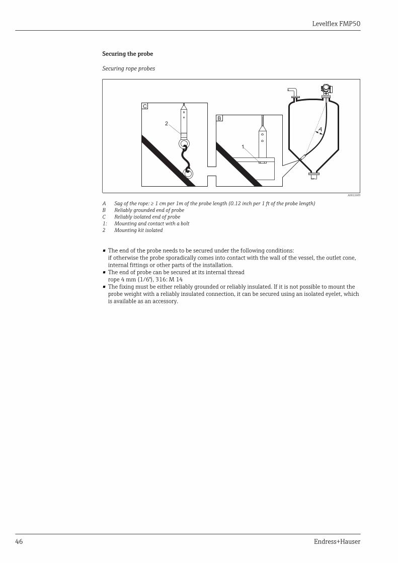
Securing the probe
Securing rope probes
1
A
C
B
2
A0012609
A Sag of the rope: ≥ 1 cm per 1m of the probe length (0.12 inch per 1 ft of the probe length)B Reliably grounded end of probeC Reliably isolated end of probe1: Mounting and contact with a bolt2 Mounting kit isolated
• The end of the probe needs to be secured under the following conditions:if otherwise the probe sporadically comes into contact with the wall of the vessel, the outlet cone,internal fittings or other parts of the installation.
• The end of probe can be secured at its internal threadrope 4 mm (1/6"), 316: M 14
• The fixing must be either reliably grounded or reliably insulated. If it is not possible to mount theprobe weight with a reliably insulated connection, it can be secured using an isolated eyelet, whichis available as an accessory.
Levelflex FMP50
Endress+Hauser 47
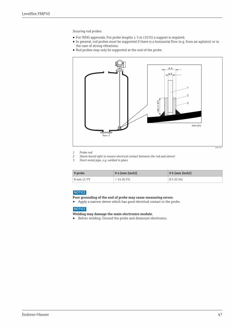
Securing rod probes
• For WHG approvals: For probe lengths ≥ 3 m (10 ft) a support is required.• In general, rod probes must be supported if there is a horizontal flow (e.g. from an agitator) or in
the case of strong vibrations.• Rod probes may only be supported at the end of the probe.
mm (in)
ø a
ø b
»5
0 (
1.9
7)
1
2
3
A0014127
1 Probe rod2 Sleeve bored tight to ensure electrical contact between the rod and sleeve!3 Short metal pipe, e.g. welded in place
probe a [mm (inch)] b [mm (inch)]
8 mm (1/3") < 14 (0.55) 8.5 (0.34)
NOTICEPoor grounding of the end of probe may cause measuring errors.‣ Apply a narrow sleeve which has good electrical contact to the probe.
NOTICEWelding may damage the main electronics module.‣ Before welding: Ground the probe and dismount electronics.
Levelflex FMP50
48 Endress+Hauser
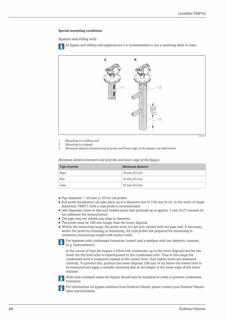
Special mounting conditions
Bypasses and stilling wells
In bypass and stilling well applications it is recommended to use a centering disks or stars.
A B
³1
00
(3.9
4)
3
21
A0014129
1 Mounting in a stilling well2 Mounting in a bypass3 Minimum distance between end of probe and lower edge of the bypass; see table below
Minimum distance between end of probe and lower edge of the bypass
Type of probe Minimum distance
Rope 10 mm (0.4 in)
Rod 10 mm (0.4 in)
Coax 10 mm (0.4 in)
• Pipe diameter: > 40 mm (1.6") for rod probes• Rod probe installation can take place up to a diameter size of 150 mm (6 in). In the event of larger
diameters, FMP51 with a coax probe is recommended.• Side disposals, holes or slits and welded joints that protrude up to approx. 5 mm (0.2") inwards do
not influence the measurement.• The pipe may not exhibit any steps in diameter.• The probe must be 100 mm longer than the lower disposal.• Within the measuring range, the probe must not get into contact with the pipe wall. If necessary,
secure the probe by retaining or tensioning. All rope probes are prepared for tensioning incontainers (tensioning weight with anchor hole).
For bypasses with condensate formation (water) and a medium with low dielectric constant(e.g. hydrocarbons):
In the course of time the bypass is filled with condensate up to the lower disposal and for lowlevels the the level echo is superimposed by the condensate echo. Thus in this range thecondensate level is measured instead of the correct level. Only higher levels are measuredcorrectly. To prevent this, position the lower disposal 100 mm (4 in) below the lowest level tobe measured and apply a metallic centering disk at the height of the lower edge of the lowerdisposal.With heat insulated tanks the bypass should also be insulated in order to prevent condensateformation.For information on bypass solutions from Endress+Hauser please contact your Endress+Hausersales representative.
Levelflex FMP50
Endress+Hauser 49
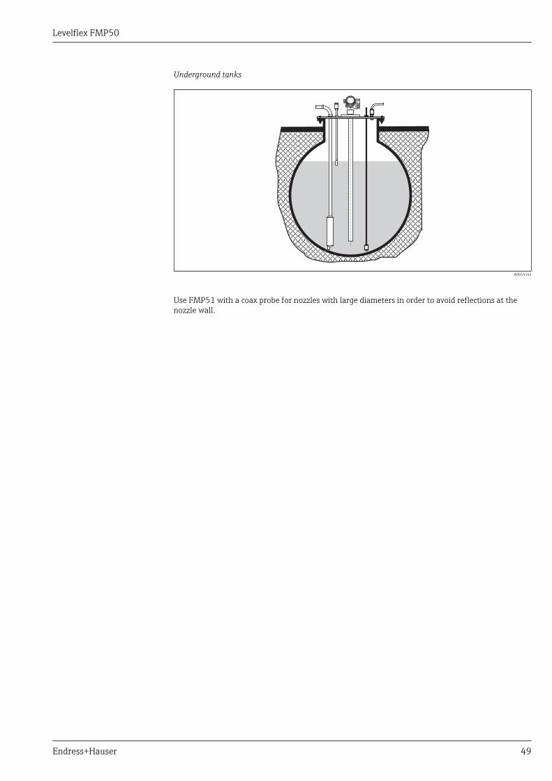
Underground tanks
A0014142
Use FMP51 with a coax probe for nozzles with large diameters in order to avoid reflections at thenozzle wall.
Levelflex FMP50
50 Endress+Hauser
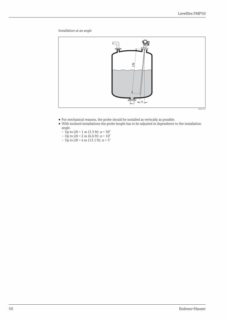
Installation at an angle
a
LN
A0014145
• For mechanical reasons, the probe should be installed as vertically as possible.• With inclined installations the probe length has to be adjusted in dependence to the installation
angle.– Up to LN = 1 m (3.3 ft): α = 30°– Up to LN = 2 m (6.6 ft): α = 10°– Up to LN = 4 m (13.1 ft): α = 5°
Levelflex FMP50
Endress+Hauser 51
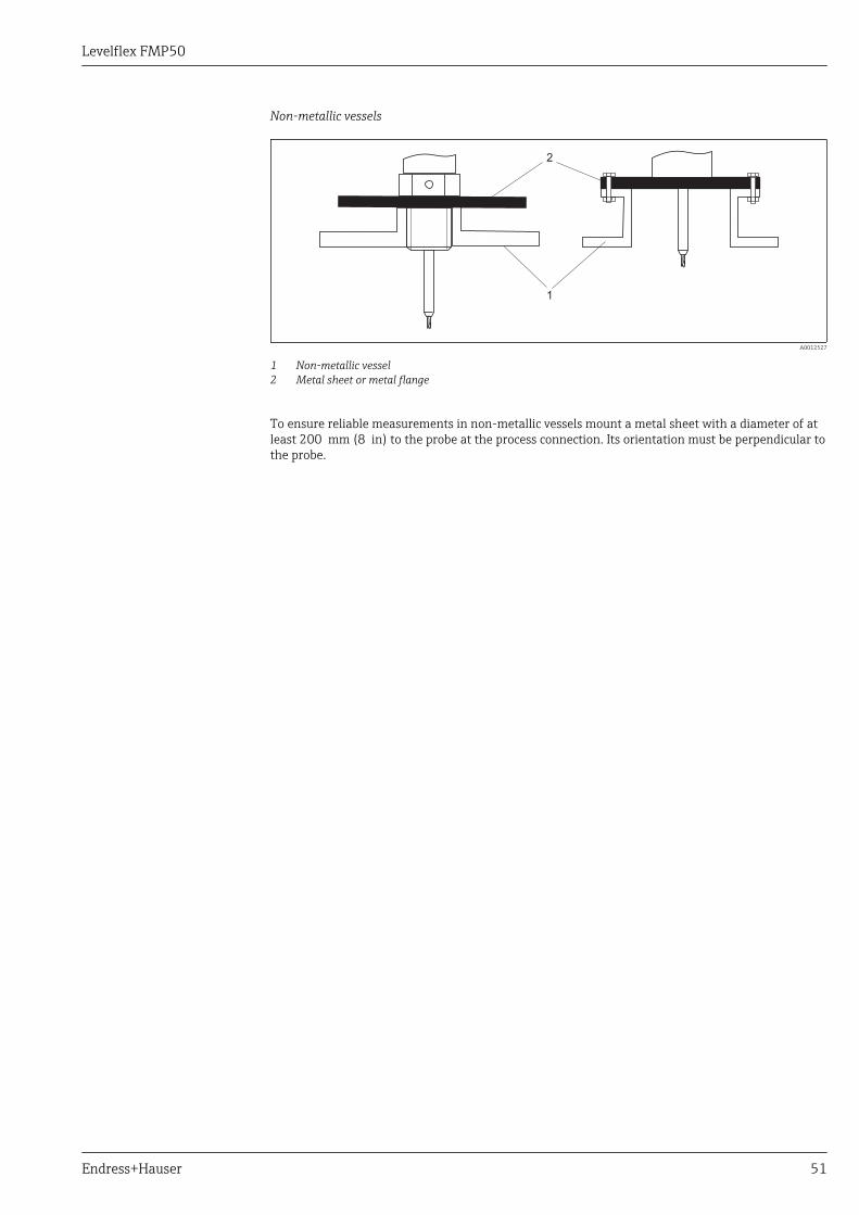
Non-metallic vessels
1
2
A0012527
1 Non-metallic vessel2 Metal sheet or metal flange
To ensure reliable measurements in non-metallic vessels mount a metal sheet with a diameter of atleast 200 mm (8 in) to the probe at the process connection. Its orientation must be perpendicular tothe probe.
Levelflex FMP50
52 Endress+Hauser
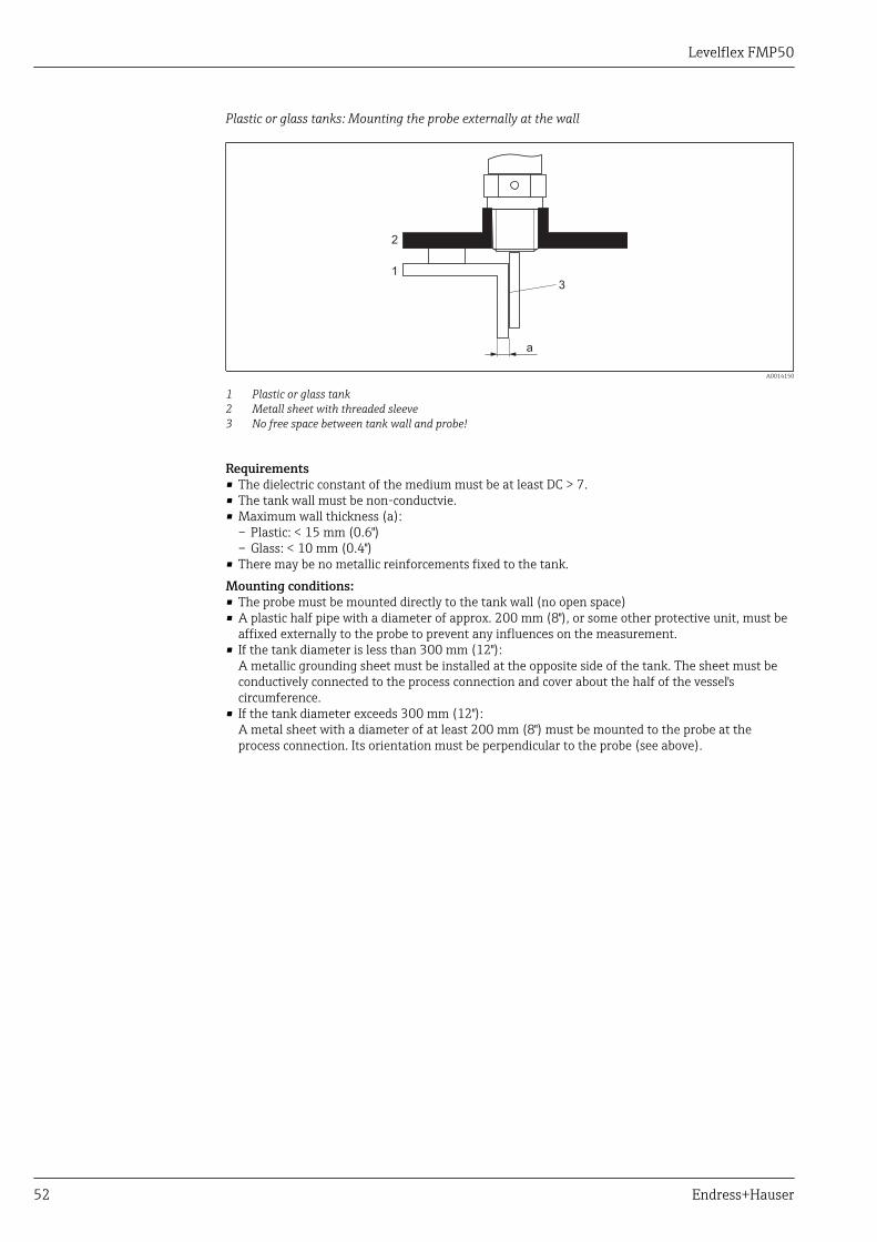
Plastic or glass tanks: Mounting the probe externally at the wall
1
2
a
3
A0014150
1 Plastic or glass tank2 Metall sheet with threaded sleeve3 No free space between tank wall and probe!
Requirements• The dielectric constant of the medium must be at least DC > 7.• The tank wall must be non-conductvie.• Maximum wall thickness (a):
– Plastic: < 15 mm (0.6")– Glass: < 10 mm (0.4")
• There may be no metallic reinforcements fixed to the tank.Mounting conditions:• The probe must be mounted directly to the tank wall (no open space)• A plastic half pipe with a diameter of approx. 200 mm (8"), or some other protective unit, must be
affixed externally to the probe to prevent any influences on the measurement.• If the tank diameter is less than 300 mm (12"):
A metallic grounding sheet must be installed at the opposite side of the tank. The sheet must beconductively connected to the process connection and cover about the half of the vessel'scircumference.
• If the tank diameter exceeds 300 mm (12"):A metal sheet with a diameter of at least 200 mm (8") must be mounted to the probe at theprocess connection. Its orientation must be perpendicular to the probe (see above).
Levelflex FMP50
Endress+Hauser 53
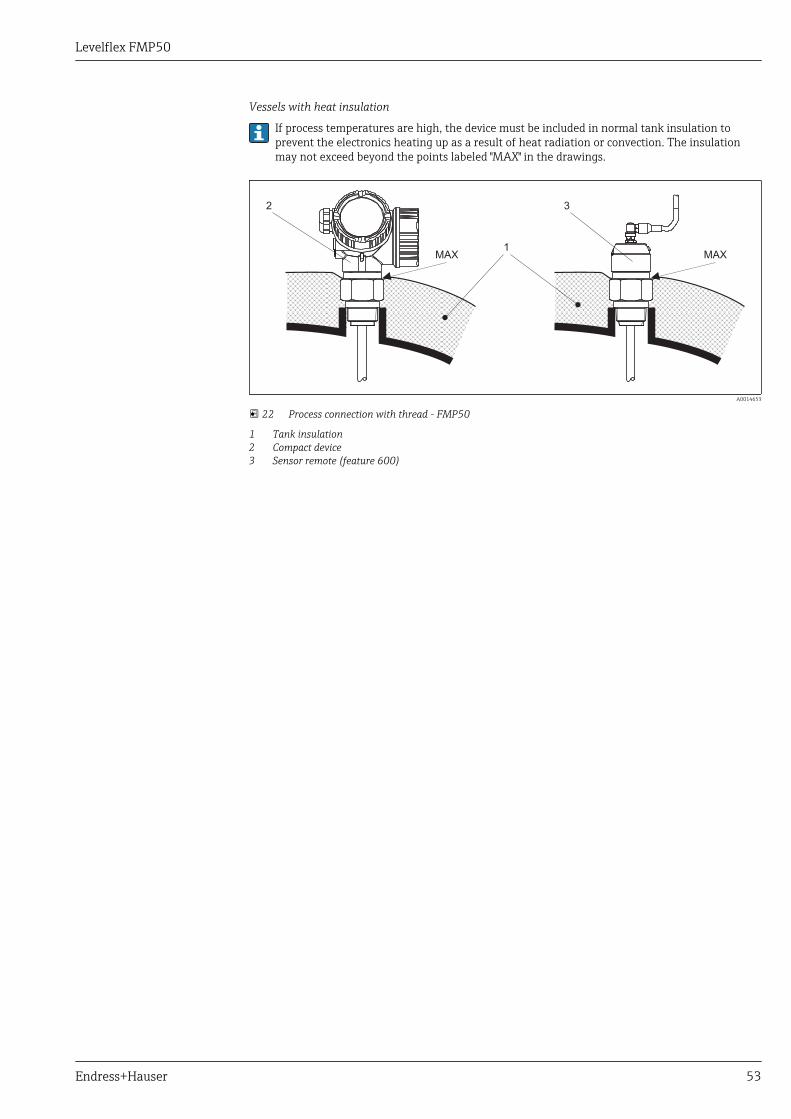
Vessels with heat insulation
If process temperatures are high, the device must be included in normal tank insulation toprevent the electronics heating up as a result of heat radiation or convection. The insulationmay not exceed beyond the points labeled "MAX" in the drawings.
MAX1
3
MAX
2
A0014653
22 Process connection with thread - FMP50
1 Tank insulation2 Compact device3 Sensor remote (feature 600)
Levelflex FMP50
54 Endress+Hauser
Operating conditions: Environment
Ambient temperature range Measuring device –20 to +80 °C (–4 to +176 °F)
Local display –20 to +70 °C (–4 to +158 °F), the readability of the display may be impaired attemperatures outside the temperature range.
Connection cable (for"Probe Design" = "Sensorremote")
max. 100 °C (212 °F)
Remote display FHX50 –40 to 80 °C (–40 to 176 °F)
Remote display FHX50(option)
–50 to 80 °C (–58 to 176 °F) 1)
1) This range is valid if option JN "Ambient temperature transmitter –50 °C (–58 °F)" has been selected inordering feature 580 "Test, Certificate". If the temperature is permanently below –40 °C (–40 °F), failurerates may be increased.
When operating the device in the open with strong sunlight:• Mount the device in a shady position.• Avoid direct sunlight, especially in warmer regions.• Use a weather protection cover (see accessories).
Ambient temperature limits The following diagrams take into account only function requirements. There may be furtherrestrictions for certified device versions. Please refere to the separate Safety Instructions.
Levelflex FMP50
Endress+Hauser 55
With a temperature (Tp) at the process connection the admissible ambient temperature (Ta) isreduced according to the following diagram (temperature derating):
Temperature derating for FMP50 with threaded connection G¾ or NPT¾
[°C] ([°F])Ta
[°C] ([°F])Ta
[°C] ([°F])Ta
[°C] ([°F])Ta
[°C]
[°C]
[°C]
[°C]
([°F])
([°F])
([°F])
([°F])
T
T
T
T
p
p
p
p+80
(+176)
+74 +80
+80
(+165) (+176)
(+176)
-20
-20
-20
-20
(-4)
(-4)
(-4)
(-4)
GT20
GT19: +73(+163)
+80(+176)
GT20: +79 (+174)GT19: +74 (+165)
-20(-4)
-20(-4)
-20(-4)
-20(-4)
Ta
Tp
4...20 mA HARTA:
4...20 mA HART
4...20 mAC:
90...253 VACK:
10.4...48 VDCL:
+76 (+169)
+74(+164)
GT20:
GT20:
+73(+163)
+76(+168)
+74 (+164)
PROFIBUS PAFOUNDATION Fieldbus
Switch output
G :2
+76 +80(+169) (+176)
PROFIBUS PAFOUNDATION Fieldbus
G :1
A0013944
GT19 = plastic housingGT20 = aluminum housing
A = 1 current outputC = 2 current outputsG1, G2 = PROFIBUS PA 1)
K, L = 4-wire
Ta = ambient temperatureTp = temperature at the process connection
1) For PROFIBUS PA and FOUNDATION Fieldbus the temperature derating depends on the usage of theswitch output. (G1: switch output not connected; G2: switch output connected).
Levelflex FMP50
56 Endress+Hauser
Storage temperature –40 to +80 °C (–40 to +176 °F)
Climate class DIN EN 60068-2-38 (test Z/AD)
Altitude according toIEC61010-1 Ed.3
• Generally up to 2 000 m (6 600 ft) above MSL.• Above 2 000 m (6 600 ft) if the following conditions are met:
– Ordering feature 020 "Power supply; Output" = A, B, C, E or G (2-wire versions)– Supply voltage U < 35 V– Supply voltage of overvoltage category 1
Degree of protection • With closed housing tested according to:– IP68, NEMA6P (24 h at 1.83 m under water surface) 5)
– For plastic housing with transparent cover (display module): IP68 (24 h at 1.00 m under watersurface) 6)
– IP66, NEMA4X• With open housing: IP20, NEMA1• Display module: IP22, NEMA2
Degree of protection IP68 NEMA6P applies for M12 PROFIBUS PA plugs only when thePROFIBUS cable is plugged in and is also rated IP68 NEMA6P.
Vibration resistance DIN EN 60068-2-64 / IEC 60068-2-64: 20 to 2 000 Hz, 1 (m/s2)2/Hz
Cleaning the probe Depending on the application, contamination or buildup can accumulate on the probe. A thin, evenlayer only influences measurement slightly. Thick layers can dampen the signal and then reduce themeasuring range. Severe, uneven buildup, adhesion e.g. through crystallization, can lead to incorrectmeasurement. In this case, we recommend that you use a non-contact measuring principle, or checkthe probe regularly for soiling.
Electromagneticcompatibility (EMC)
Electromagnetic compatibility to all relevant requirements of the EN 61326- series and NAMURrecommendation EMC (NE21). For details see declaration of conformity 7). If only the analoguesignal is used, unshielded interconnection lines are sufficient for the installation. In case of using thedigital signal (HART/ PA/ FF) use shielded interconnection lines.
Use a shielded cable when working with a digital communications signal.
Max. fluctuations during EMC- tests: < 0.5 % of the span.
When installing the probes in metal and concrete tanks and when using a coax probe:• Interference emission to EN 61326 - x series, electrical equipment Class B.• Interference immunity to EN 61326 - x series, requirements for industrial areas and NAMUR
Recommendation NE 21 (EMC)The measured value can be affected by strong electromagnetic fields when installing rod and ropeprobes without a shielding/metallic wall, e.g. in plastic and wooden silos.• Interference emission to EN 61326 - x series, electrical equipment Class A.• Interference immunity: the measured value can be affected by strong electromagnetic fields.
5) also valid for the "Sensor remote" version6) This restriction is valid if the following options of the product structure have been selected at the same time: 030 ("Display, Operation") = C
("SD02") or E ("SD03"); 040 ("Housing") = A ("GT19").7) Can be downloaded from www.endress.com.
Levelflex FMP50
Endress+Hauser 57
Process
Process temperature range The maximum permitted temperature at the process connection is determined by the O-ring versionordered:
Device O-ring material Process temperature
FMP50 FKM (Viton GLT) –20 to +80 °C (–4 to 176 °F)
Process pressure range Device Process pressure
FMP50 –1 to 6 bar (–14.5 to 87 psi)
Dielectric constant (DC) Rod and rope probe: DC (εr) ≥ 1.6
Expansion of the rope probesthrough temperature
Elongation through temperature increase from 30 °C (86 °F) to 80 °C (176 °F): 1 mm / m rope length
Levelflex FMP50
58 Endress+Hauser
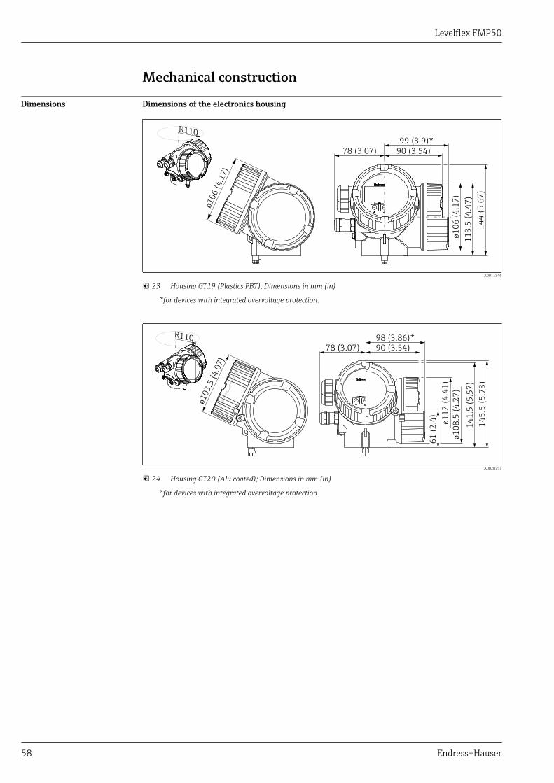
Mechanical construction
Dimensions Dimensions of the electronics housing
14
4 (
5.6
7)
11
3.5
(4
.47
)
ø1
06
(4
.17
)
78 (3.07) 90 (3.54)
99 (3.9)*
ø10
6 (
4.1
7)
R110
A0011346
23 Housing GT19 (Plastics PBT); Dimensions in mm (in)
*for devices with integrated overvoltage protection.
14
5.5
(5
.73
)
14
1.5
(5
.57
)
ø1
12
(4
.41
)
ø1
08
.5 (
4.2
7)
78 (3.07) 90 (3.54)98 (3.86)*
ø10
3.5
(4
.07
)
R110
61
(2
.4)
A0020751
24 Housing GT20 (Alu coated); Dimensions in mm (in)
*for devices with integrated overvoltage protection.
Levelflex FMP50
Endress+Hauser 59
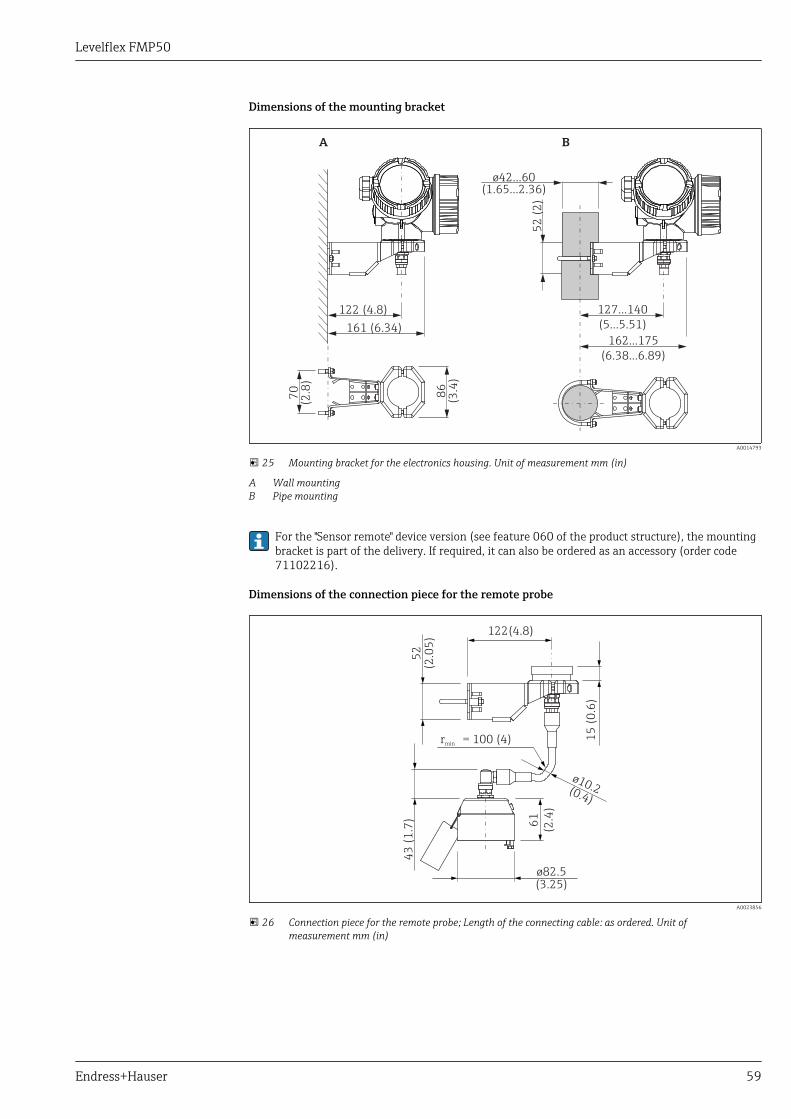
Dimensions of the mounting bracket
122 (4.8)
52
(2
)
86
(3.4
)
70
(2.8
)127...140
(5...5.51)161 (6.34)162...175
(6.38...6.89)
A B
ø42...60(1.65...2.36)
A0014793
25 Mounting bracket for the electronics housing. Unit of measurement mm (in)
A Wall mountingB Pipe mounting
For the "Sensor remote" device version (see feature 060 of the product structure), the mountingbracket is part of the delivery. If required, it can also be ordered as an accessory (order code71102216).
Dimensions of the connection piece for the remote probe
122(4.8)
52
(2.0
5)
15
(0
.6)
61
(2.4
)
ø82.5(3.25)
ø10.2(0.4)
rmin = 100 (4)
43
(1
.7)
A0023856
26 Connection piece for the remote probe; Length of the connecting cable: as ordered. Unit ofmeasurement mm (in)

Levelflex FMP50
60 Endress+Hauser
FMP50 : Dimensions of process connection and probe
ø8 (0.31)
ø4 (0.16)
69
(2
.72
)
G¾NPT¾
25
(0.9
8)
15
0 (
5.9
1)
ø22 (0.87)
M14
29
.5 (
1.1
6)
LN
B C
A
R
36 mm
7 mm 7 mm
A0012644
27 FMP50: Process connection / probe. Unit of measurement mm (in)
A Thread ISO228 G3/4 or ANSI MNPT3/4 (Feature 100)B Rod probe 8mm or 1/3" (Feature 060)C Rope probe 4mm or 1/6" (Feature 060)LN Length of probeR Reference point of the measurement
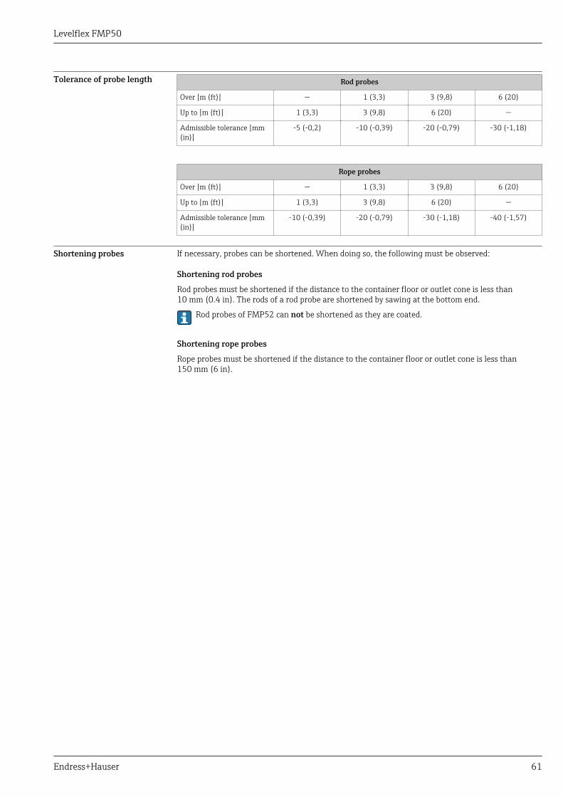
Levelflex FMP50
Endress+Hauser 61
Tolerance of probe length Rod probes
Over [m (ft)] — 1 (3,3) 3 (9,8) 6 (20)
Up to [m (ft)] 1 (3,3) 3 (9,8) 6 (20) —
Admissible tolerance [mm(in)]
-5 (-0,2) -10 (-0,39) -20 (-0,79) -30 (-1,18)
Rope probes
Over [m (ft)] — 1 (3,3) 3 (9,8) 6 (20)
Up to [m (ft)] 1 (3,3) 3 (9,8) 6 (20) —
Admissible tolerance [mm(in)]
-10 (-0,39) -20 (-0,79) -30 (-1,18) -40 (-1,57)
Shortening probes If necessary, probes can be shortened. When doing so, the following must be observed:
Shortening rod probes
Rod probes must be shortened if the distance to the container floor or outlet cone is less than10 mm (0.4 in). The rods of a rod probe are shortened by sawing at the bottom end.
Rod probes of FMP52 can not be shortened as they are coated.
Shortening rope probes
Rope probes must be shortened if the distance to the container floor or outlet cone is less than150 mm (6 in).

Levelflex FMP50
62 Endress+Hauser
Weight Housing
Part Weight
Housing GT19 - plastic approx. 1.2 kg
Housing GT20 - aluminium approx. 1.9 kg
FMP50
Part Weight Part Weight
Sensor approx. 0.25 kg Rope probe 4 mm approx. 0.1 kg/m probe length
Rod probe 8 mm approx. 0.4 kg/m probe length
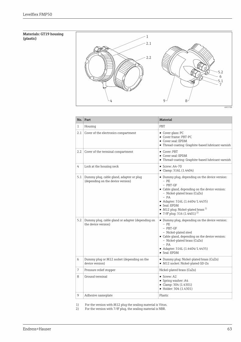
Levelflex FMP50
Endress+Hauser 63
Materials: GT19 housing(plastic)
2.1
1
2.2
5.2
5.1
6
7
894
A0013788
No. Part Material
1 Housing PBT
2.1 Cover of the electronics compartment • Cover glass: PC• Cover frame: PBT-PC• Cover seal: EPDM• Thread-coating: Graphite-based lubricant varnish
2.2 Cover of the terminal compartment • Cover: PBT• Cover seal: EPDM• Thread-coating: Graphite-based lubricant varnish
4 Lock at the housing neck • Screw: A4-70• Clamp: 316L (1.4404)
5.1 Dummy plug, cable gland, adapter or plug(depending on the device version)
• Dummy plug, depending on the device version:– PE– PBT-GF
• Cable gland, depending on the device version:– Nickel-plated brass (CuZn)– PA
• Adapter: 316L (1.4404/1.4435)• Seal: EPDM• M12 plug: Nickel-plated brass 1)
• 7/8" plug: 316 (1.4401) 2)
5.2 Dummy plug, cable gland or adapter (depending onthe device version)
• Dummy plug, depending on the device version:– PE– PBT-GF– Nickel-plated steel
• Cable gland, depending on the device version:– Nickel-plated brass (CuZn)– PA
• Adapter: 316L (1.4404/1.4435)• Seal: EPDM
6 Dummy plug or M12 socket (depending on thedevice version)
• Dummy plug: Nickel-plated brass (CuZn)• M12 socket: Nickel-plated GD-Zn
7 Pressure relief stopper Nickel-plated brass (CuZn)
8 Ground terminal • Screw: A2• Spring washer: A4• Clamp: 304 (1.4301)• Holder: 304 (1.4301)
9 Adhesive nameplate Plastic
1) For the version with M12 plug the sealing material is Viton.2) For the version with 7/8" plug, the sealing material is NBR.

Levelflex FMP50
64 Endress+Hauser
Materials: GT20 housing(die-cast aluminum, powder-coated) 2.1
1
2.2
5.2
5.1
6
7
8934
A0036037
Nr. Part Material
1 Housing, RAL 5012 (blue) • Housing: AlSi10Mg(<0,1% Cu)• Coating: Polyester
2.1 Cover of the electronics compartment; RAL 7035(gray)
• Cover: AlSi10Mg(<0,1% Cu)• Window: Glass• Cover seal: NBR• Seal of the window: NBR• Thread-coating: Graphite-based lubricant varnish
2.2 Cover of the terminal compartment; RAL 7035(gray)
• Cover: AlSi10Mg(<0,1% Cu)• Cover seal: NBR• Thread-coating: Graphite-based lubricant varnish
3 Cover lock • Screw: A4• Clamp: 316L (1.4404)
4 Lock at the housing neck • Screw: A4-70• Clamp: 316L (1.4404)
5.1 Dummy plug, cable gland, adapter or plug(depending on the device version)
• Dummy plug, depending on the device version:– PE– PBT-GF
• Cable gland, depending on the device version:– Nickel-plated brass (CuZn)– PA
• Adapter: 316L (1.4404/1.4435)• Seal: EPDM• M12 plug: Nickel-plated brass 1)
• 7/8" plug: 316 (1.4401) 2)
5.2 Dummy plug, cable gland or adapter (depending onthe device version)
• Dummy plug, depending on the device version:– PE– PBT-GF– Nickel-plated steel
• Cable gland, depending on the device version:– Nickel-plated brass (CuZn)– PA
• Adapter: 316L (1.4404/1.4435)• Seal: EPDM
6 Dummy plug or M12 socket (depending on thedevice version)
• Dummy plug : Nickel-plated brass (CuZn)• M12 socket: Nickel-plated GD-Zn
7 Pressure relief stopper Nickel-plated brass (CuZn)

Levelflex FMP50
Endress+Hauser 65
Nr. Part Material
8 Ground terminal • Screw: A2• Spring washer: A2• Clamp: 304 (1.4301)• Holder: 304 (1.4301)
9 Adhesive nameplate Plastic
1) For the version with M12 plug the sealing material is Viton.2) For the version with 7/8" plug, the sealing material is NBR.
Levelflex FMP50
66 Endress+Hauser
Materials: Processconnection
Levelflex FMP50
Threaded connectionNo. Material
G¾, NPT¾
1
2
3
A0013834
1 PPS-GF40
2 316L (1.4404)
3 PPS-GF40
Levelflex FMP50
Endress+Hauser 67
Materials: Probe Levelflex FMP50
Feature 060 "Probe"Pos. Material• AA: rod 8mm
• AB: rod 1/3"• LA: rope 4mm• LB: rope 1/6"
1
A0036583
1
2
3
1
4
A0036584
1 316L (1.4404)
2 316 (1.4401)
3 Set screw: A4-70
4 Screw for tightening: A2-70
Levelflex FMP50
68 Endress+Hauser
Materials: Mounting bracket
1011
12
12
A0015143
Mounting bracket for version "Sensor remote"
Position Part Material
10 Bracket 316L (1.4404)
11 Bracket 316Ti (1.4571)
Screw/nuts A4-70
Distance sleeves 316Ti (1.4571) or 316L (1.4404)
12 Half-shells 316L (1.4404)
Levelflex FMP50
Endress+Hauser 69
Materials: Adapter and cablefor remote sensor
1
2
34
A0021722
Adapter and cable for version "Sensor remote"
Position Part Material
1 Cable FRNC
2 Sensor adapter 304 (1.4301)
3 Clamp 316L (1.4404)
Screw A4-70
4 Loop 316 (1.4401)
Crimp sleeve Aluminum
Nameplate 304 (1.4301)

Levelflex FMP50
70 Endress+Hauser
Materials: Weatherprotection cover
1
2
3
4
5
6
A0015473
No Part: Material
1 Protection cover: 316L (1.4404)
2 Molded rubber part (4x): EPDM
3 Clamping screw: 316L (1.4404) + carbon fibre
4 Bracket: 316L (1.4404)
5 Ground terminal• Screw: A4• Spring washer: A4• Clamp: 316L (1.4404)• Holder: 316L (1.4404)
6 • Washer: A4• Cheese head screw: A4-70
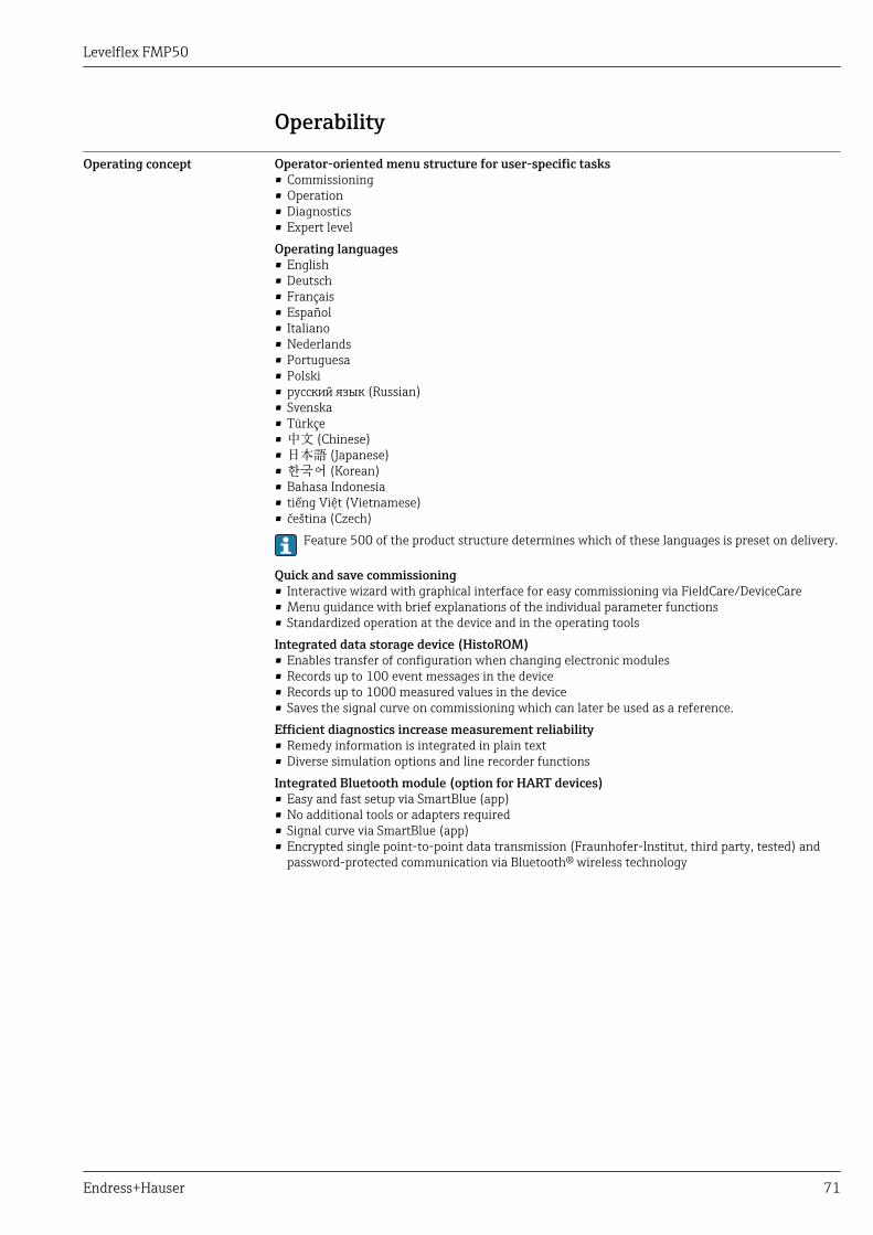
Levelflex FMP50
Endress+Hauser 71
Operability
Operating concept Operator-oriented menu structure for user-specific tasks• Commissioning• Operation• Diagnostics• Expert levelOperating languages• English• Deutsch• Français• Español• Italiano• Nederlands• Portuguesa• Polski• русский язык (Russian)• Svenska• Türkçe• 中文 (Chinese)• 日本語 (Japanese)• 한국어 (Korean)• Bahasa Indonesia• tiếng Việt (Vietnamese)• čeština (Czech)
Feature 500 of the product structure determines which of these languages is preset on delivery.
Quick and save commissioning• Interactive wizard with graphical interface for easy commissioning via FieldCare/DeviceCare• Menu guidance with brief explanations of the individual parameter functions• Standardized operation at the device and in the operating toolsIntegrated data storage device (HistoROM)• Enables transfer of configuration when changing electronic modules• Records up to 100 event messages in the device• Records up to 1000 measured values in the device• Saves the signal curve on commissioning which can later be used as a reference.Efficient diagnostics increase measurement reliability• Remedy information is integrated in plain text• Diverse simulation options and line recorder functionsIntegrated Bluetooth module (option for HART devices)• Easy and fast setup via SmartBlue (app)• No additional tools or adapters required• Signal curve via SmartBlue (app)• Encrypted single point-to-point data transmission (Fraunhofer-Institut, third party, tested) and
password-protected communication via Bluetooth® wireless technology
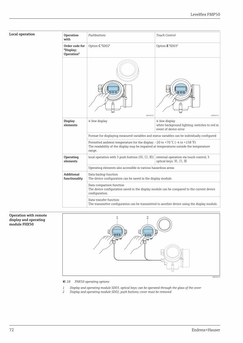
Levelflex FMP50
72 Endress+Hauser
Local operation Operationwith
Pushbuttons Touch Control
Order code for"Display;Operation"
Option C "SD02" Option E "SD03"
A0036312 A0036313
Displayelements
4-line display 4-line displaywhite background lighting; switches to red inevent of device error
Format for displaying measured variables and status variables can be individually configured
Permitted ambient temperature for the display: –20 to +70 °C (–4 to +158 °F)The readability of the display may be impaired at temperatures outside the temperaturerange.
Operatingelements
local operation with 3 push buttons (, , ) external operation via touch control; 3optical keys: , ,
Operating elements also accessible in various hazardous areas
Additionalfunctionality
Data backup functionThe device configuration can be saved in the display module.
Data comparison functionThe device configuration saved in the display module can be compared to the current deviceconfiguration.
Data transfer functionThe transmitter configuration can be transmitted to another device using the display module.
Operation with remotedisplay and operatingmodule FHX50
1 2
A0036314
28 FHX50 operating options
1 Display and operating module SD03, optical keys; can be operated through the glass of the cover2 Display and operating module SD02, push buttons; cover must be removed
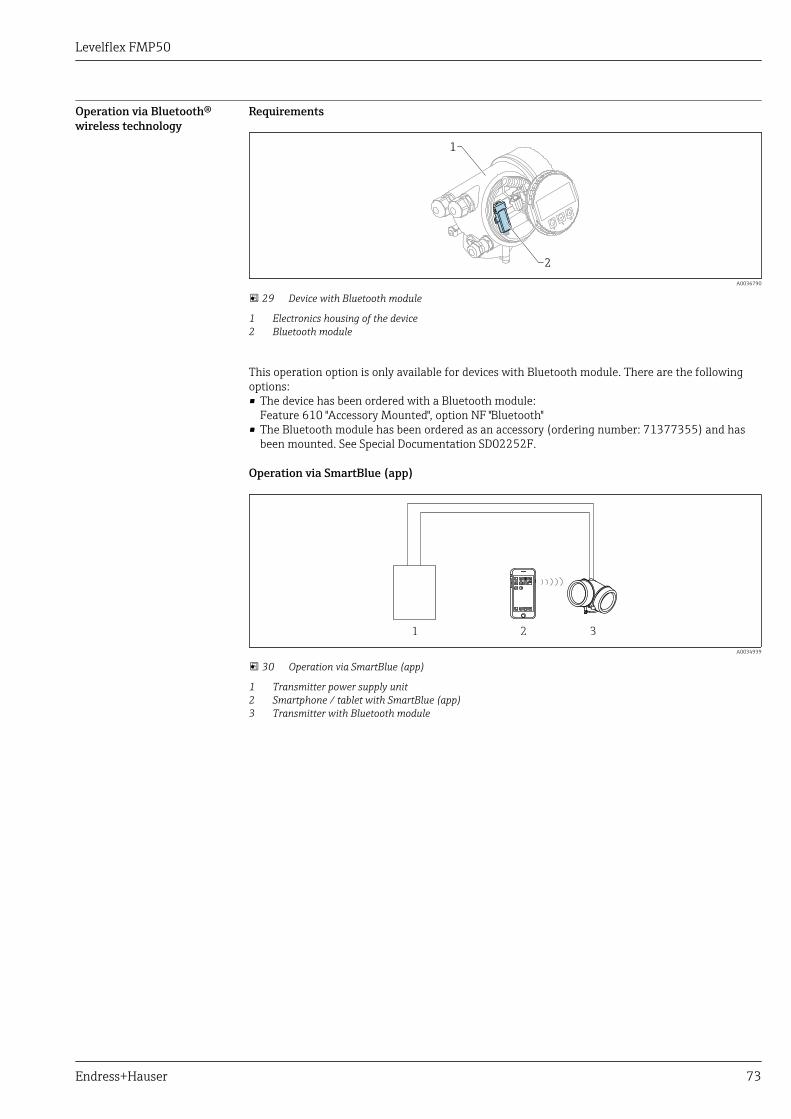
Levelflex FMP50
Endress+Hauser 73
Operation via Bluetooth®wireless technology
Requirements
1
2
A0036790
29 Device with Bluetooth module
1 Electronics housing of the device2 Bluetooth module
This operation option is only available for devices with Bluetooth module. There are the followingoptions:• The device has been ordered with a Bluetooth module:
Feature 610 "Accessory Mounted", option NF "Bluetooth"• The Bluetooth module has been ordered as an accessory (ordering number: 71377355) and has
been mounted. See Special Documentation SD02252F.
Operation via SmartBlue (app)
1 2 3
A0034939
30 Operation via SmartBlue (app)
1 Transmitter power supply unit2 Smartphone / tablet with SmartBlue (app)3 Transmitter with Bluetooth module
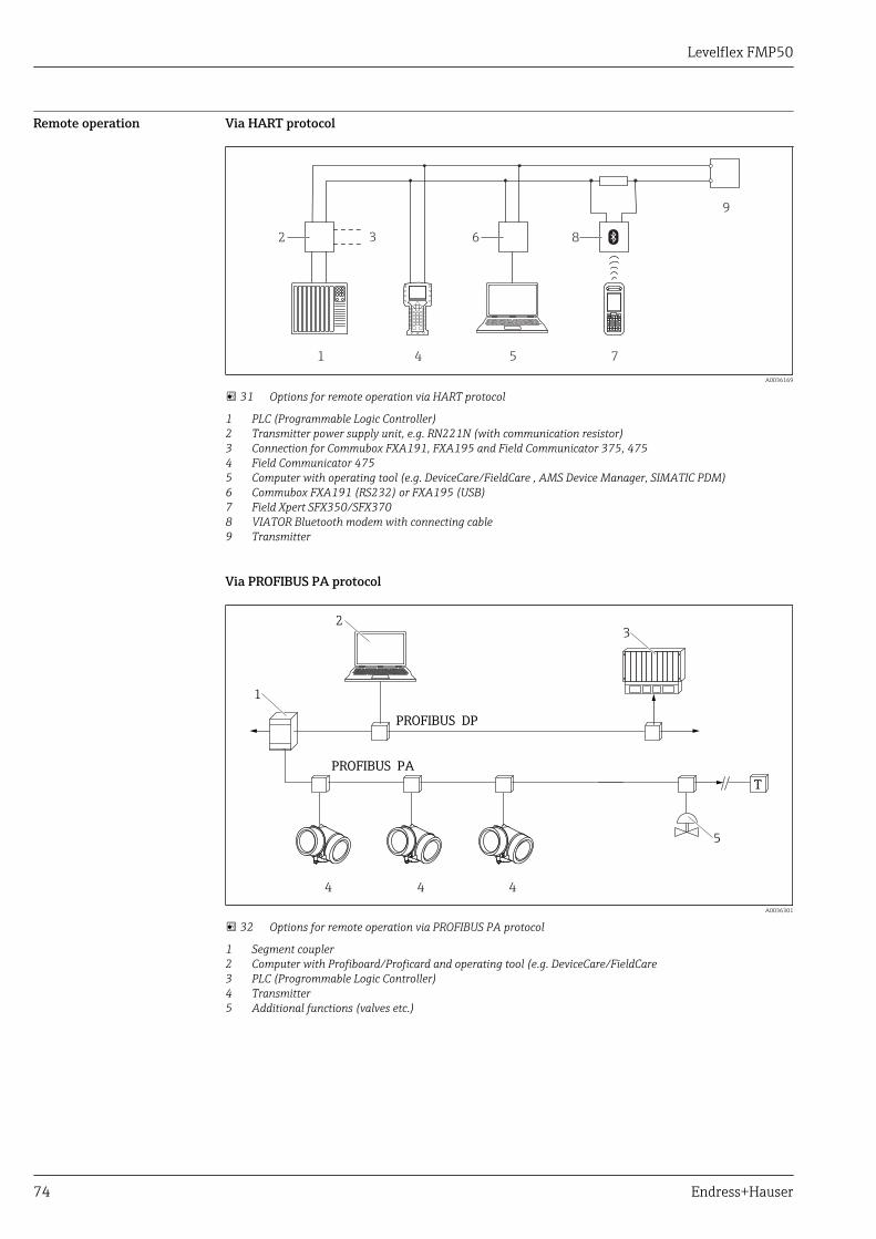
Levelflex FMP50
74 Endress+Hauser
Remote operation Via HART protocol
1 4 5 7
9
6 82 3
A0036169
31 Options for remote operation via HART protocol
1 PLC (Programmable Logic Controller)2 Transmitter power supply unit, e.g. RN221N (with communication resistor)3 Connection for Commubox FXA191, FXA195 and Field Communicator 375, 4754 Field Communicator 4755 Computer with operating tool (e.g. DeviceCare/FieldCare , AMS Device Manager, SIMATIC PDM)6 Commubox FXA191 (RS232) or FXA195 (USB)7 Field Xpert SFX350/SFX3708 VIATOR Bluetooth modem with connecting cable9 Transmitter
Via PROFIBUS PA protocol
PROFIBUS DP
PROFIBUS PA
1
2
3
5
4 4 4
T
A0036301
32 Options for remote operation via PROFIBUS PA protocol
1 Segment coupler2 Computer with Profiboard/Proficard and operating tool (e.g. DeviceCare/FieldCare3 PLC (Progrommable Logic Controller)4 Transmitter5 Additional functions (valves etc.)
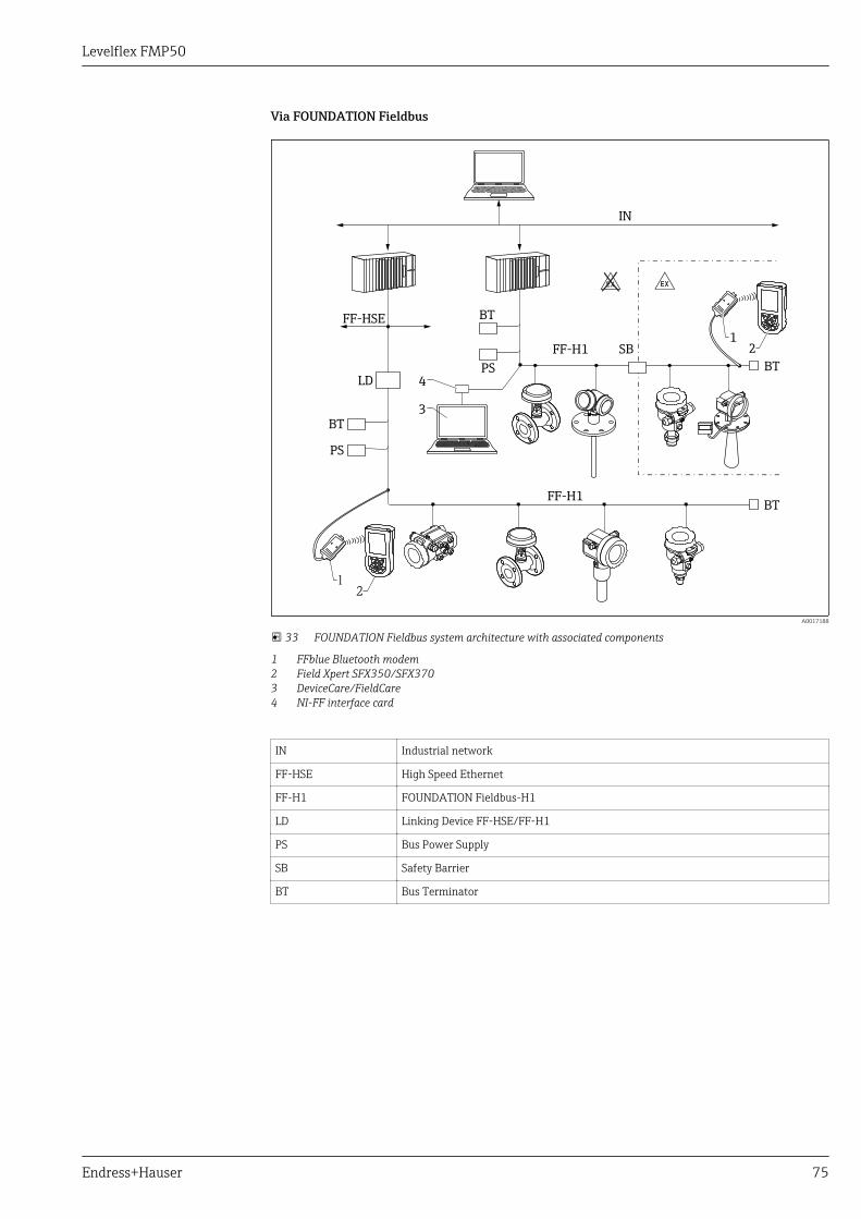
Levelflex FMP50
Endress+Hauser 75
Via FOUNDATION Fieldbus
FF-H1
FF-H1
BT
BT
PS
3
4
PS
BT
SB
BT
FF-HSE
IN
LD
1
1
2
2
-.
A0017188
33 FOUNDATION Fieldbus system architecture with associated components
1 FFblue Bluetooth modem2 Field Xpert SFX350/SFX3703 DeviceCare/FieldCare4 NI-FF interface card
IN Industrial network
FF-HSE High Speed Ethernet
FF-H1 FOUNDATION Fieldbus-H1
LD Linking Device FF-HSE/FF-H1
PS Bus Power Supply
SB Safety Barrier
BT Bus Terminator

Levelflex FMP50
76 Endress+Hauser
DeviceCare/FieldCare via service interface (CDI)
1
2
3
A0032466
34 DeviceCare/FieldCare via service interface (CDI)
1 Service interface (CDI) of the instrument (= Endress+Hauser Common Data Interface)2 Commubox FXA2913 Computer with DeviceCare/FieldCare operating tool
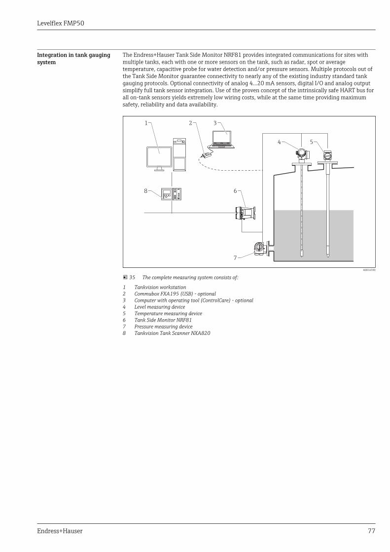
Levelflex FMP50
Endress+Hauser 77
Integration in tank gaugingsystem
The Endress+Hauser Tank Side Monitor NRF81 provides integrated communications for sites withmultiple tanks, each with one or more sensors on the tank, such as radar, spot or averagetemperature, capacitive probe for water detection and/or pressure sensors. Multiple protocols out ofthe Tank Side Monitor guarantee connectivity to nearly any of the existing industry standard tankgauging protocols. Optional connectivity of analog 4...20 mA sensors, digital I/O and analog outputsimplify full tank sensor integration. Use of the proven concept of the intrinsically safe HART bus forall on-tank sensors yields extremely low wiring costs, while at the same time providing maximumsafety, reliability and data availability.
1 2 3
4
6
7
8
5
A0016590
35 The complete measuring system consists of:
1 Tankvision workstation2 Commubox FXA195 (USB) - optional3 Computer with operating tool (ControlCare) - optional4 Level measuring device5 Temperature measuring device6 Tank Side Monitor NRF817 Pressure measuring device8 Tankvision Tank Scanner NXA820
Levelflex FMP50
78 Endress+Hauser
SupplyCare inventorymanagement software
SupplyCare is a web-based operating program for coordinating the flow of material and informationalong the supply chain. SupplyCare provides a comprehensive overview of the levels ofgeographically distributed tanks and silos, for instance, providing complete transparency over thecurrent inventory situation, regardless of time and location.
Based on the measuring and transmission technology installed onsite, the current inventory data arecollected and sent to SupplyCare. Critical levels are clearly indicated and calculated forecasts provideadditional security for material requirements planning.
The main functions of SupplyCare:
Inventory visualization
SupplyCare determines the inventory levels in tanks and silos at regular intervals. It displays currentand historical inventory data and calculated forecasts of future demand. The overview page can beconfigured to suit the user's preferences.
Master data management
With SupplyCare you can create and manage the master data for locations, companies, tanks,products and users, as well as user authorization.
Report Configurator
The Report Configurator can be used to create personalized reports quickly and easily. The reportscan be saved in a variety of formats, such as Excel, PDF, CSV and XML. The reports can betransmitted in many ways, such as by http, ftp or e-mail.
Event management
Events, such as when levels drop below the safety stock level or plan points, are indicated by thesoftware. In addition, SupplyCare can also notify pre-defined users by e-mail.
Alarms
If technical problems occur, e.g. connection issues, alarms are triggered and alarm e-mails are sent tothe System Administrator and the Local System Administrator.
Delivery planning
The integrated delivery planning function automatically generates an order proposal if a pre-setminimum inventory level is undershot. Scheduled deliveries and disposals are monitoredcontinuously by SupplyCare. SupplyCare notifies the user if scheduled deliveries and disposals are notgoing to be met as planned.
Analysis
In the Analysis module, the most important indicators for the inflow and outflow of the individualtanks are calculated and displayed as data and charts. Key indicators of material management areautomatically calculated and form the basis for optimizing the delivery and storage process.
Geographical visualization
All the tanks and the tank inventories are represented graphically on a map (based on Google Maps).The tanks and inventory situations can be filtered by tank group, product, supplier or location.
Multi-language support
The multi-language user interface supports 9 languages, thereby enabling global collaboration on asingle platform. The language and settings are recognized automatically using the browser settings.
SupplyCare Enterprise
SupplyCare Enterprise runs by default as a service under Microsoft Windows on an application serverin an Apache Tomcat environment. The operators and administrators operate the application via aWeb browser from their workstations.
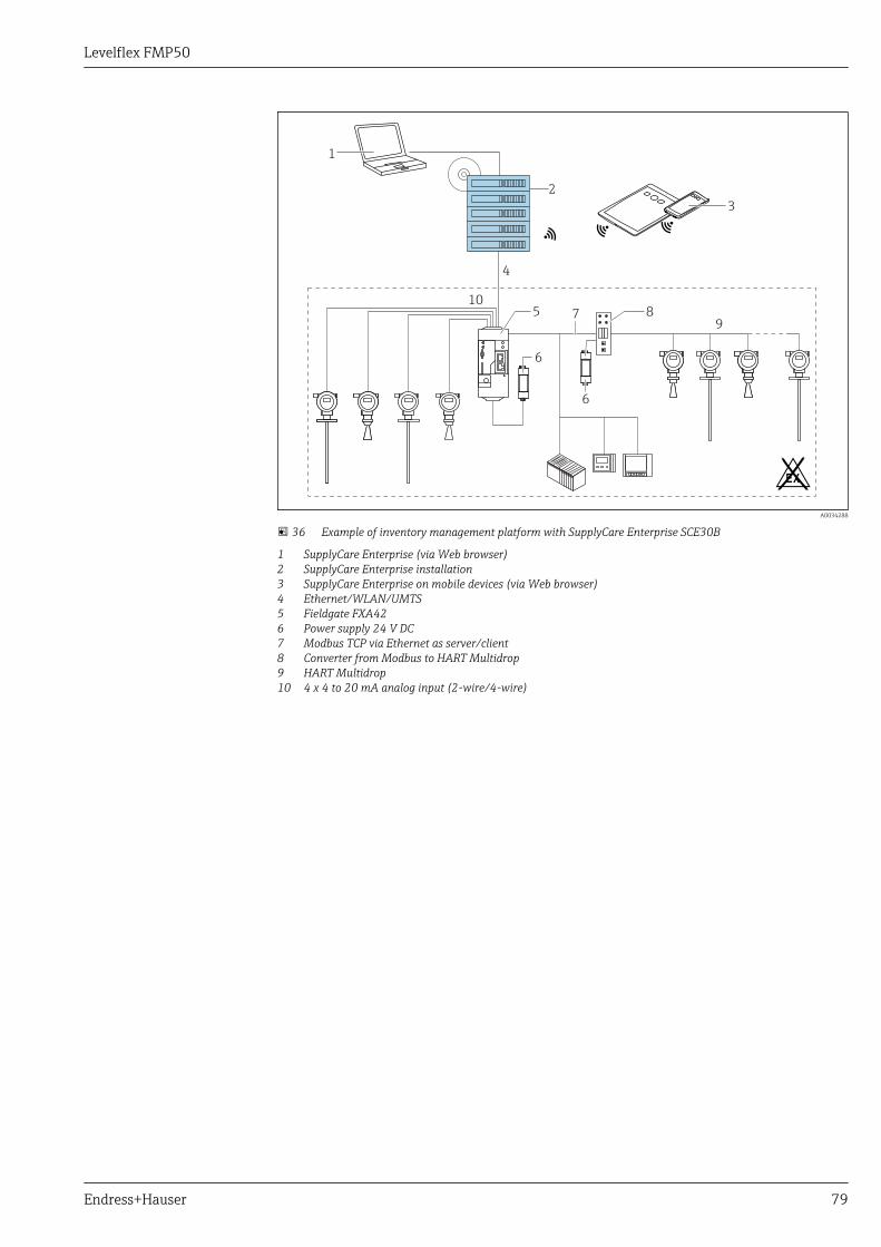
Levelflex FMP50
Endress+Hauser 79
6
.
10
9
1
3
4
6
5 87
2
A0034288
36 Example of inventory management platform with SupplyCare Enterprise SCE30B
1 SupplyCare Enterprise (via Web browser)2 SupplyCare Enterprise installation3 SupplyCare Enterprise on mobile devices (via Web browser)4 Ethernet/WLAN/UMTS5 Fieldgate FXA426 Power supply 24 V DC7 Modbus TCP via Ethernet as server/client8 Converter from Modbus to HART Multidrop9 HART Multidrop10 4 x 4 to 20 mA analog input (2-wire/4-wire)
Levelflex FMP50
80 Endress+Hauser
Cloud-based application: SupplyCare Hosting
SupplyCare Hosting is offered as a hosting service (software as a service). Here, the software isinstalled within the Endress+Hauser IT infrastructure and made available to the user in the Endress+Hauser portal.
6
.
10
9
13
4
6
5 87
2
WWW
A0034289
37 Example of inventory management platform with SupplyCare Hosting SCH30
1 SupplyCare Hosting installation in Endress+Hauser data center2 PC workstation with Internet connection3 Warehouse locations with Internet connection via 2G/3G with FXA42 or FXA304 Warehouse locations with Internet connection with FXA425 Fieldgate FXA426 Power supply 24 V DC7 Modbus TCP via Ethernet as server/client8 Converter from Modbus to HART Multidrop9 HART Multidrop10 4 x 4 to 20 mA analog input (2-wire/4-wire)
With SupplyCare Hosting, users do not need to make the initial software purchase or install and runthe IT infrastructure needed. Endress+Hauser constantly update SupplyCare Hosting and enhancethe capability of the software in conjunction with the customer. The hosted version of SupplyCare isthus always up-to-date and can be customized to meet different customer requirements. Otherservices are also offered in addition to the IT infrastructure and the software that is installed in asecure, redundant Endress+Hauser data center. These services include defined availability of theglobal Endress+Hauser Service and Support Organization and defined response times in a serviceevent.
Levelflex FMP50
Endress+Hauser 81
Certificates and approvalsCurrently available certificates and approvals can be called up via the product configurator.
CE mark The measuring system meets the legal requirements of the applicable EC guidelines. These are listedin the corresponding EC Declaration of Conformity together with the standards applied.
Endress+Hauser confirms successful testing of the device by affixing to it the CE mark.
RoHS The measuring system complies with the substance restrictions of the Restriction on HazardousSubstances Directive 2011/65/EU (RoHS 2).
RCM-Tick marking The supplied product or measuring system meets the ACMA (Australian Communications and MediaAuthority) requirements for network integrity, interoperability, performance characteristics as wellas health and safety regulations. Here, especially the regulatory arrangements for electromagneticcompatibility are met. The products are labelled with the RCM- Tick marking on the name plate.
A0029561
Ex approval The devices are certified for use in hazardous areas and the relevant safety instructions are providedin the separate "Safety Instructions" (XA) document. Reference is made to this document on thenameplate.
The separate documentation "Safety Instructions" (XA) containing all the relevant explosionprotection data is available from your Endress+Hauser Sales Center. Correlation ofdocumentations to the device → 101.
Dual seal according toANSI/ISA 12.27.01
The devices have been designed according to ANSI/ISA 12.27.01 as dual seal devices, allowing theuser to waive the use and save the cost of installing external secondary process seals in the conduitas required by the process sealing sections of ANSI/NFPA 70 (NEC) and CSA 22.1 (CEC) Theseinstruments comply with the North-American installation practice and provide a very safe and cost-saving installation for pressurized applications with hazardous fluids.
Further information can be found in the Safety Instructions (XA) of the relevant devices.
Functional Safety Used for level monitoring (MIN, MAX, range) up to SIL 3 (homogeneous redundancy), independentlyassessed by TÜV Rhineland as per IEC 61508. Other information see documentation SD00326F:"Functional Safety Manual".
Overfill prevention WHG
DIBt Z-65.16-501
Pressure equipment withallowable pressure≤ 200 bar (2 900 psi)
Pressure instruments with a flange and threaded boss that do not have a pressurized housing do notfall within the scope of the Pressure Equipment Directive, irrespective of the maximum allowablepressure.
Reasons:
According to Article 2, point 5 of EU Directive 2014/68/EU, pressure accessories are defined as"devices with an operational function and having pressure-bearing housings".
If a pressure instrument does not have a pressure-bearing housing (no identifiable pressure chamberof its own), there is no pressure accessory present within the meaning of the Directive.
Telecommunications Complies with part 15 of the FCC rules for an unintentional radiator. All probes meet therequirements for a Class A digital device.
In addition, all probes in metallic tanks as well as the coax probe meet the requirements for a Class Bdigital device.
Levelflex FMP50
82 Endress+Hauser
Test, Certificate Feature 580 "Test, Certificate" Designation Available for
JA 3.1 Material certificate, wetted metallic parts, EN10204-3.1inspection certificate
FMP50
Test reports, declarations and material test certificates can be obtained electronically from theW@M Device Viewer :Enter the serial number from the nameplate (www.endress.com/deviceviewer)This applies to the options of the following ordering features:• 550 "Calibration"• 580 "Test, Certificate"
Product documentation onpaper
Test reports, declarations and material certificates can be ordered as hardcopies via ordering feature570 "Service", option I7 „Product documentation on paper“. The printouts will be enclosed in theproduct delivery.
Levelflex FMP50
Endress+Hauser 83
Other standards andguidelines
• EN 60529Degrees of protection by housing (IP code)
• EN 61010-1Protection Measures for Electrical Equipment for Measurement, Control, Regulation andLaboratory Procedures.
• IEC/EN 61326"Emission in accordance with Class A requirements". Electromagnetic compatibility (EMCrequirements)
• NAMUR NE 21Electromagnetic compatibility (EMC) of industrial process and laboratory control equipment.
• NAMUR NE 43Standardization of the signal level for the breakdown information of digital transmitters withanalog output signal.
• NAMUR NE 53Software of field devices and signal-processing devices with digital electronics
• NAMUR NE 107Status classification as per NE107
• NAMUR NE 131Requirements for field devices for standard applications
• IEC61508Functional safety of electrical/electronic/programmable electronic safety-related systems

Levelflex FMP50
84 Endress+Hauser
Ordering information
Ordering information Detailed ordering information is available from the following sources:• In the Product Configurator on the Endress+Hauser website: www.endress.com -> Click "Corporate"
-> Select your country -> Click "Products" -> Select the product using the filters and search field ->Open product page -> The "Configure" button to the right of the product image opens the ProductConfigurator.
• From your Endress+Hauser Sales Center: www.addresses.endress.comProduct Configurator - the tool for individual product configuration• Up-to-the-minute configuration data• Depending on the device: Direct input of measuring point-specific information such as
measuring range or operating language• Automatic verification of exclusion criteria• Automatic creation of the order code and its breakdown in PDF or Excel output format• Ability to order directly in the Endress+Hauser Online Shop
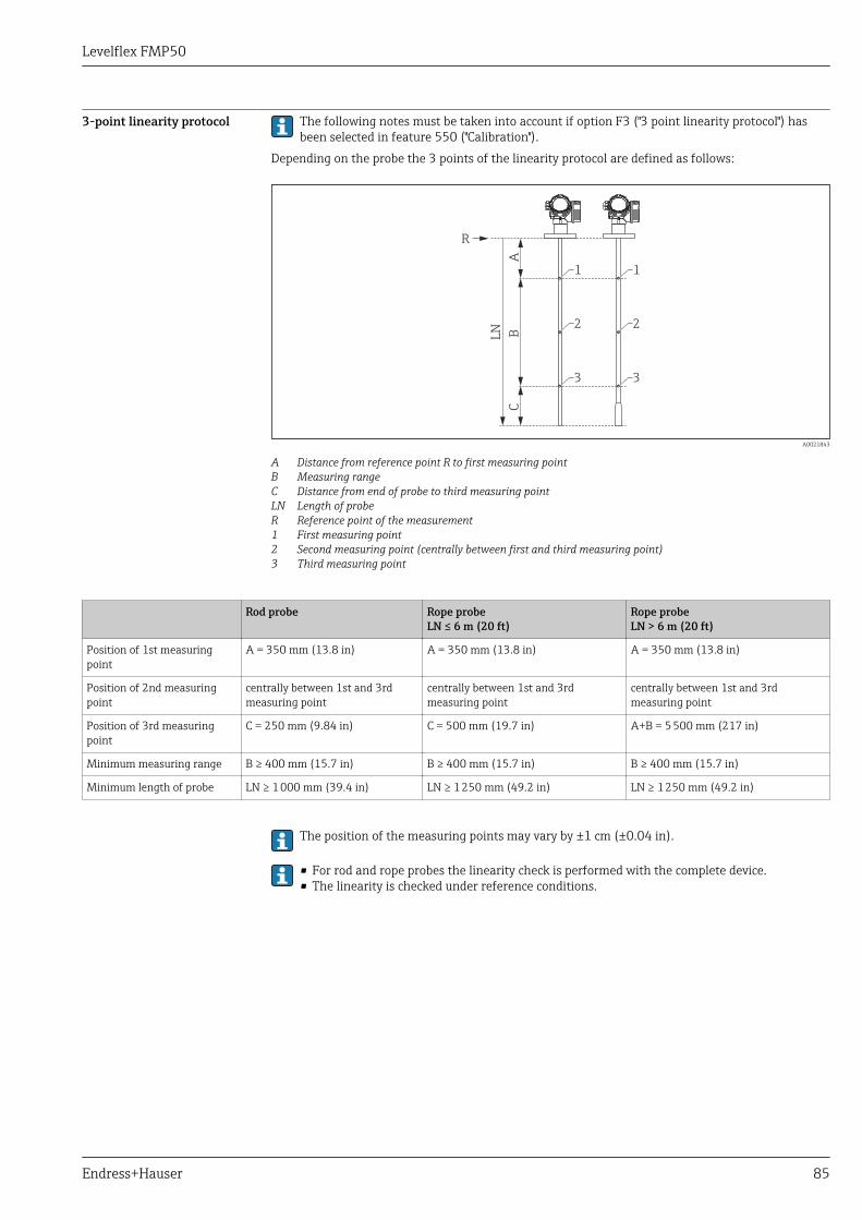
Levelflex FMP50
Endress+Hauser 85
3-point linearity protocol The following notes must be taken into account if option F3 ("3 point linearity protocol") hasbeen selected in feature 550 ("Calibration").
Depending on the probe the 3 points of the linearity protocol are defined as follows:
R
AC
BLN
1 1
3 3
2 2
A0021843
A Distance from reference point R to first measuring pointB Measuring rangeC Distance from end of probe to third measuring pointLN Length of probeR Reference point of the measurement1 First measuring point2 Second measuring point (centrally between first and third measuring point)3 Third measuring point
Rod probe Rope probeLN ≤ 6 m (20 ft)
Rope probeLN > 6 m (20 ft)
Position of 1st measuringpoint
A = 350 mm (13.8 in) A = 350 mm (13.8 in) A = 350 mm (13.8 in)
Position of 2nd measuringpoint
centrally between 1st and 3rdmeasuring point
centrally between 1st and 3rdmeasuring point
centrally between 1st and 3rdmeasuring point
Position of 3rd measuringpoint
C = 250 mm (9.84 in) C = 500 mm (19.7 in) A+B = 5 500 mm (217 in)
Minimum measuring range B ≥ 400 mm (15.7 in) B ≥ 400 mm (15.7 in) B ≥ 400 mm (15.7 in)
Minimum length of probe LN ≥ 1 000 mm (39.4 in) LN ≥ 1 250 mm (49.2 in) LN ≥ 1 250 mm (49.2 in)
The position of the measuring points may vary by ±1 cm (±0.04 in).
• For rod and rope probes the linearity check is performed with the complete device.• The linearity is checked under reference conditions.
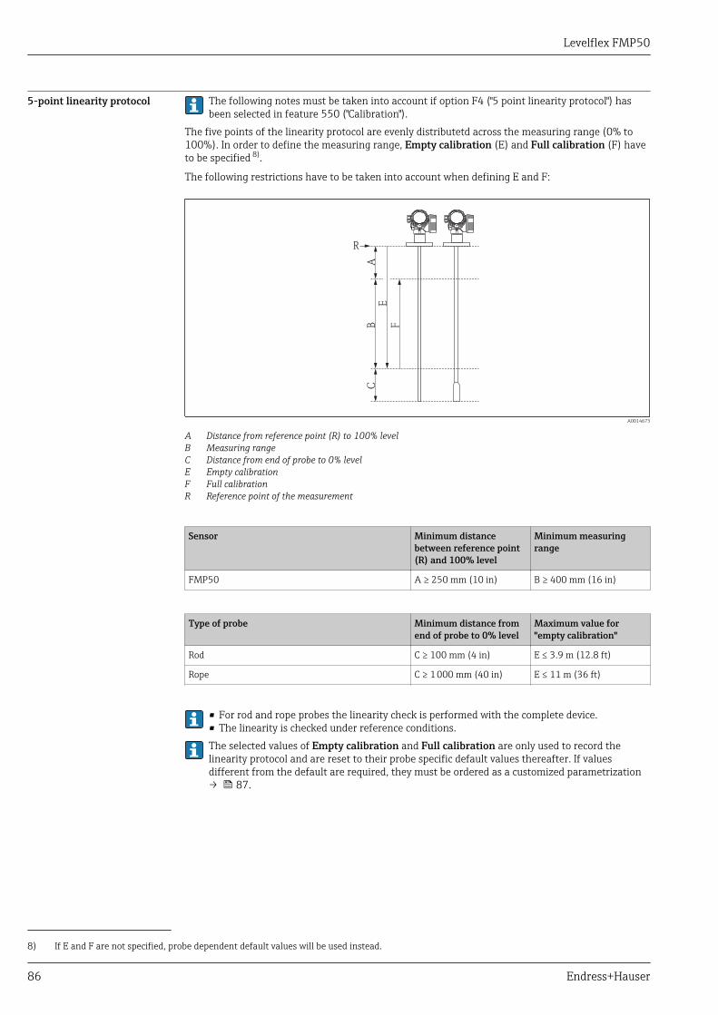
Levelflex FMP50
86 Endress+Hauser
5-point linearity protocol The following notes must be taken into account if option F4 ("5 point linearity protocol") hasbeen selected in feature 550 ("Calibration").
The five points of the linearity protocol are evenly distributetd across the measuring range (0% to100%). In order to define the measuring range, Empty calibration (E) and Full calibration (F) haveto be specified 8).
The following restrictions have to be taken into account when defining E and F:
R
AC
B F
E
A0014673
A Distance from reference point (R) to 100% levelB Measuring rangeC Distance from end of probe to 0% levelE Empty calibrationF Full calibrationR Reference point of the measurement
Sensor Minimum distancebetween reference point(R) and 100% level
Minimum measuringrange
FMP50 A ≥ 250 mm (10 in) B ≥ 400 mm (16 in)
Type of probe Minimum distance fromend of probe to 0% level
Maximum value for"empty calibration"
Rod C ≥ 100 mm (4 in) E ≤ 3.9 m (12.8 ft)
Rope C ≥ 1 000 mm (40 in) E ≤ 11 m (36 ft)
• For rod and rope probes the linearity check is performed with the complete device.• The linearity is checked under reference conditions.The selected values of Empty calibration and Full calibration are only used to record thelinearity protocol and are reset to their probe specific default values thereafter. If valuesdifferent from the default are required, they must be ordered as a customized parametrization→ 87.
8) If E and F are not specified, probe dependent default values will be used instead.
Levelflex FMP50
Endress+Hauser 87
Customized parametrization If the option IJ "Customized parametrization HART", IK "Customized parametrization PA" or IL"Customized parametrization FF" has been selected in feature 570 "Service", customer specificpresettings can be selected for the following parameters:
Parameter Communication Selection list / range ofvalues
Setup → Distance unit • HART• PA• FF
• in• ft• mm• m
Setup → Empty calibration • HART• PA• FF
0 to 12 m (0 to 36 ft)
Setup → Full calibration • HART• PA• FF
0 to 12 m (0 to 36 ft)
Setup → Adv. Setup → Current output 1/2 → Damping HART 0 to 999.9 s
Setup → Adv. Setup → Current output 1/2 → Failure mode HART • Min• Max• Last valid value
Setup → Adv. Setup → Current output 1/2 → Burst mode HART • Off• On
Tagging (TAG) Ordering feature 895: Marking
Option Z1: Tagging (TAG), see additional spec.
Position of the measuringpoint marking
To be selected in the additional specifications:• Tag plate Stainless Steel• Self-adhesive paper label• Supplied label/plate• RFID TAG• RFID TAG + Tag plate Stainless Steel• RFID TAG + Self-adhesive paper label• RFID TAG + Supplied label/plate
Definition of the measuringpoint designation
To be defined in the additional specifications:3 lines containing up to 18 characters each
The measuring point designation appears on the selected label and/or theRFID TAG.
Designation in the ElectronicName Plate (ENP)
The first 32 characters of the measuring point designation
Designation on the displaymodule
The first 12 characters of the measuring point designation
Levelflex FMP50
88 Endress+Hauser
Application Packages
Heartbeat Diagnostics Availability
Available in all device versions.
Function
• Continuous self-monitoring of the device.• Diagnostic messages output to
– the local display.– an asset management system (e.g. FieldCare/DeviceCare).– an automation system (e.g. PLC).
Advantages
• Device condition information is available immediately and processed in time.• The status signals are classified in accordance with VDI/VDE 2650 and NAMUR recommendation
NE 107 and contain information about the cause of the error and remedial action.
Detailed description
See Operating Instructions of the device (→ 100); chapter "Diagnostics and trouble shooting"
Levelflex FMP50
Endress+Hauser 89
Heartbeat Verification Availability
Available for the following options of feature 540 "Application Package":• EH: Heartbeat Verification + Monitoring• EJ: Heartbeat Verification
Device functionality checked on demand
• Verification of the correct functioning of the measuring device within specifications.• The verification result provides information about the condition of the device: Passed or Failed.• The results are documented in a verification report.• The automatically generated report supports the obligation to demonstrate compliance with
internal and external regulations, laws and standards.• Verification is possible without interrupting the process.
Advantages
• No onsite presence is required to use the function.• The DTM 9) triggers verification in the device and interprets the results. No specific knowledge is
required on the part of the user.• The verification report can be used to prove quality measures to a third party.• Heartbeat Verification can replace other maintenance tasks (e.g. periodic check) or extend the
test intervals.
SIL/WHG-locked devices 10)
• The Heartbeat Verification module contains a wizard for the proof test which must be performedat appropriate intervals for the following applications:– SIL (IEC61508/IEC61511)– WHG (German Water Resources Act)
• To perform a proof test, the device must be locked (SIL/WHG locking).• The wizard can be used via FieldCare, DeviceCare or a DTM-based process control system.
In the case of SIL-locked and WHG-locked devices, it is not possible to perform verificationwithout additional measures (e.g. by-passing of the output current) because the output currentmust be simulated (Increased safety mode) or the level must be approached manually (Expertmode) during subsequent re-locking (SIL/WHG locking).
Detailed description
SD01872F
9) DTM: Device Type Manager; controls device operation via DeviceCare, FieldCare or a DTM-based process control system.10) Only relevant for devices with SIL or WHG approval: order code 590 ("Additional approval"), option LA ("SIL") or LC ("WHG").
Levelflex FMP50
90 Endress+Hauser
Heartbeat Monitoring Availability
Available for the following options of feature 540 "Application Package":EH: Heartbeat Verification + Monitoring
Function
• In addition to the verification parameters, the corresponding parameter values are also logged.• Existing measured variables, such as the echo amplitude, are used in the Foam detection and
Build-up detection wizards.For Levelflex FMP5x, the Foam detection and Build-up detection wizards cannot be usedtogether.
"Foam detection" wizard
• The Heartbeat Monitoring module contains the Foam detection wizard.• This wizard is used to configure automatic foam detection, which detects foam on the product
surface on the basis of the reduced signal amplitude. Foam detection can be linked to a switchoutput in order to control a sprinkler system, for example, which dissolves the foam.
• This wizard can be used via FieldCare, DeviceCare or a DTM-based process control system.
"Build-up detection" wizard
• The Heartbeat Monitoring module contains the Build-up detection wizard.• The wizard is used to configure automatic buildup detection, which detects the buildup of deposits
on the probe on the basis of the reduced signal amplitude.• This wizard can be used via FieldCare, DeviceCare or a DTM-based process control system.
Advantages
• Early detection of changes (trends) to ensure plant availability and product quality.• Use of information for the proactive planning of measures (e.g. cleaning/maintenance).• Identification of undesirable process conditions as the basis to optimizing the facility and the
processes.• Automated control of measures to remove foam or buildup.
Detailed description
SD01872F
Levelflex FMP50
Endress+Hauser 91
Accessories
Device-specific accessories Weather protection cover
Accessory Description
Weather protection cover
22
2 (
8.7
4)
A0015466
300 (11.8) 275 (10.8)
255.1 (10)
15
6(6
.14
)
38
(1.5
)
164 (6.46) 54 (2.13)
35
°65
°
55
°
A0015472
38 Weather protection cover; Dimensions: mm (in)
The weather protection cover can be ordered together with the device (product structure, feature 620 "AccessoryEnclosed", option PB "Weather Protection Cover").Alternatively, it can be separately ordered as an accessory; order code 71162242.

Levelflex FMP50
92 Endress+Hauser
Mounting bracket for the electronics housing
Accessory Description
Mounting bracket for theelectronics housing
122 (4.8)
52
(2
)
86
(3.4
)
70
(2.8
)
127...140
(5...5.51)161 (6.34)162...175
(6.38...6.89)
A B
ø42...60(1.65...2.36)
A0014793
39 Mounting bracket for the electronics housing; Dimensions: mm (in)
A Wall mountingB Pipe mounting
For the "Sensor remote" device version (see feature 060 of the product structure), the mounting bracket is part ofthe delivery. If required, it can also be ordered as an accessory (order code 71102216).
Levelflex FMP50
Endress+Hauser 93
Mounting kit, isolated
Accessory Description
Mounting kit, isolated
can be used forFMP50
D
1
2
A0013586
40 Scope of supply of the mounting kit:
1 Insulating sleeve2 Eye-bolt
For reliably insulated fixing of the probe.Maximum process temperature: 150 °C (300 °F)
For rope probes 4 mm (¹⁄₆ in) or 6 mm (1/4 in) with PA>steel:• Diameter D = 20 mm (0.8 in)• Order-No.: 52014249
For rope probes 6 mm (¹⁄₄ in) or 8 mm (1/3 in) with PA>steel:• Diameter D = 25 mm (1 in)• Order-No.: 52014250
Due to the risk of electrostatic charge, the insulating sleeve is not suitable for usein hazardous areas. In these cases the fixing must be reliably grounded.
The mounting kit can also be ordered directly with the device (see theLevelflex product structure, feature 620 "Accessory Enclosed", option PG"Mounting kit, isolated, rope").

Levelflex FMP50
94 Endress+Hauser
Centering star
Accessory Description
Centering star PFA
• 16.4 mm (0.65 in)• 37 mm (1.46 in)
can be used for
FMP50
10
(0
.39
)
A:
ø1
6.4
(0
.65
)
B:
ø3
7 (
1.4
6)
A0014577
A For 8 mm (0.3 in) probesB: For 12 mm (0.47 in) and 16 mm (0.63 in) probes
The centering star is suitable for probes with a rod diameter of 8 mm (0.3 in),12 mm (0.47 in) and 16 mm (0.63 in) (also coated rod probes) and can be used inpipes from DN40 (1½") up to DN50 (2"). See also Operating InstructionsBA00378F/00/A2.
• Material: PFA• Admissible process temperature: –200 to +250 °C (–382 to +482 °F)• Order code
– Probe 8 mm (0.3 in): 71162453– Probe 12 mm (0.47 in): 71157270– Probe 16 mm (0.63 in): 71069065
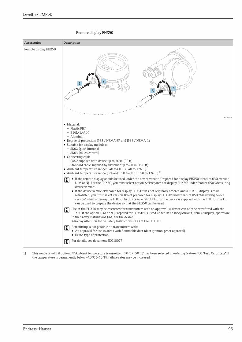
Levelflex FMP50
Endress+Hauser 95
Remote display FHX50
Accessories Description
Remote display FHX50
1.
3.
2.
4.
A0019128
• Material:– Plastic PBT– 316L/1.4404– Aluminum
• Degree of protection: IP68 / NEMA 6P and IP66 / NEMA 4x• Suitable for display modules:
– SD02 (push buttons)– SD03 (touch control)
• Connecting cable:– Cable supplied with device up to 30 m (98 ft)– Standard cable supplied by customer up to 60 m (196 ft)
• Ambient temperature range: –40 to 80 °C (–40 to 176 °F)• Ambient temperature range (option): –50 to 80 °C (–58 to 176 °F) 1)
• If the remote display should be used, order the device version "Prepared for display FHX50" (feature 030, versionL, M or N). For the FHX50, you must select option A: "Prepared for display FHX50" under feature 050 "Measuringdevice version".
• If the device version "Prepared for display FHX50" was not originally ordered and a FHX50 display is to beretrofitted, you must select version B "Not prepared for display FHX50" under feature 050: "Measuring deviceversion" when ordering the FHX50. In this case, a retrofit kit for the device is supplied with the FHX50. The kitcan be used to prepare the device so that the FHX50 can be used.
Use of the FHX50 may be restricted for transmitters with an approval. A device can only be retrofitted with theFHX50 if the option L, M or N ("Prepared for FHX50") is listed under Basic specifications, item 4 "Display, operation"in the Safety Instructions (XA) for the device.Also pay attention to the Safety Instructions (XA) of the FHX50.
Retrofitting is not possible on transmitters with:• An approval for use in areas with flammable dust (dust ignition-proof approval)• Ex nA type of protection
For details, see document SD01007F.
1) This range is valid if option JN "Ambient temperature transmitter –50 °C (–58 °F)" has been selected in ordering feature 580 "Test, Certificate". Ifthe temperature is permanently below –40 °C (–40 °F), failure rates may be increased.
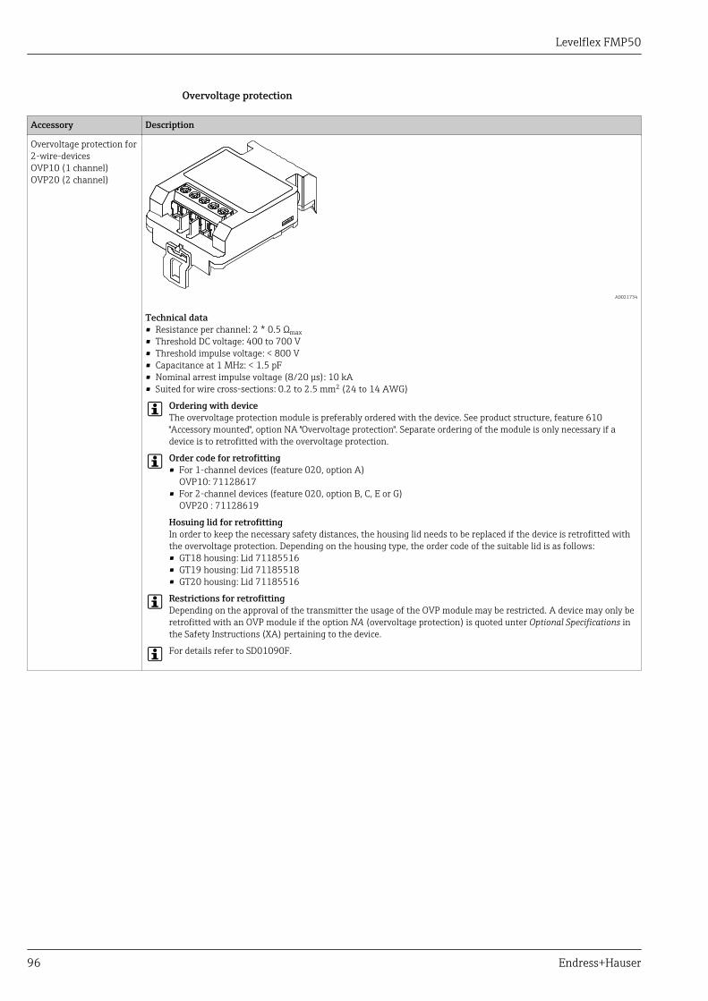
Levelflex FMP50
96 Endress+Hauser
Overvoltage protection
Accessory Description
Overvoltage protection for2-wire-devicesOVP10 (1 channel)OVP20 (2 channel)
A0021734
Technical data• Resistance per channel: 2 * 0.5 Ωmax• Threshold DC voltage: 400 to 700 V• Threshold impulse voltage: < 800 V• Capacitance at 1 MHz: < 1.5 pF• Nominal arrest impulse voltage (8/20 μs): 10 kA• Suited for wire cross-sections: 0.2 to 2.5 mm2 (24 to 14 AWG)
Ordering with deviceThe overvoltage protection module is preferably ordered with the device. See product structure, feature 610"Accessory mounted", option NA "Overvoltage protection". Separate ordering of the module is only necessary if adevice is to retrofitted with the overvoltage protection.
Order code for retrofitting• For 1-channel devices (feature 020, option A)
OVP10: 71128617• For 2-channel devices (feature 020, option B, C, E or G)
OVP20 : 71128619
Hosuing lid for retrofittingIn order to keep the necessary safety distances, the housing lid needs to be replaced if the device is retrofitted withthe overvoltage protection. Depending on the housing type, the order code of the suitable lid is as follows:• GT18 housing: Lid 71185516• GT19 housing: Lid 71185518• GT20 housing: Lid 71185516
Restrictions for retrofittingDepending on the approval of the transmitter the usage of the OVP module may be restricted. A device may only beretrofitted with an OVP module if the option NA (overvoltage protection) is quoted unter Optional Specifications inthe Safety Instructions (XA) pertaining to the device.
For details refer to SD01090F.
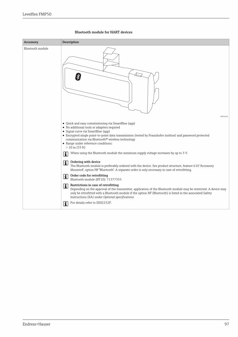
Levelflex FMP50
Endress+Hauser 97
Bluetooth module for HART devices
Accessory Description
Bluetooth module
A0036493
• Quick and easy commissioning via SmartBlue (app)• No additional tools or adapters required• Signal curve via SmartBlue (app)• Encrypted single point-to-point data transmission (tested by Fraunhofer institue) and password protected
communication via Bluetooth® wireless technology• Range under reference conditions:
> 10 m (33 ft)
When using the Bluetooth module the minimum supply voltage increases by up to 3 V.
Ordering with deviceThe Bluetooth module is preferably ordered with the device. See product structure, feature 610 "AccessoryMounted", option NF "Bluetooth". A separate order is only necessary in case of retrofitting.
Order code for retrofittingBluetooth module (BT10): 71377355
Restrictions in case of retrofittingDepending on the approval of the transmitter, application of the Bluetooth module may be restricted. A device mayonly be retrofitted with a Bluetooth module if the option NF (Bluetooth) is listed in the associated SafetyInstructions (XA) under Optional specifications.
For details refer to SD02252F.
Levelflex FMP50
98 Endress+Hauser
Communication-specificaccessories
Accessory Description
Commubox FXA195HART
For intrinsically safe HART communication with FieldCare via the USB interface.
For details refer to Technical Information TI00404F
Accessory Description
Commubox FXA291 Connects Endress+Hauser field devices with CDI interface (= Endress+HauserCommon Data Interface) to the USB interface of a computer.Order code: 51516983
For details refer to Technical Information TI00405C
Accessory Description
HART Loop ConverterHMX50
Evaluates the dynamic HART variables and converts them to analog current signalsor limit values.Order code: 71063562
For details refer to Technical Information TI00429F and OperatingInstructions BA00371F
Accessory Description
WirelessHART AdapterSWA70
Connects field devices to a WirelessHART network.The WirelessHART adapter can be mounted directly at a HART device and is easlyintegrated into an existing HART network. It ensures safe data transmission andcan be operated in parallel with other wireless networks.
For details refer to Operating Instructions BA00061S
Accessories Description
Connect SensorFXA30/FXA30B
Fully integrated, battery-powered gateway for simple applications with SupplyCare Hosting.Up to 4 field devices with 4 to 20 mA communication (FXA30/FXA30B), serial Modbus(FXA30B) or HART (FXA30B) can be connected. With its robust design and ability to run foryears on the battery, it is ideal for remote monitoring in isolated locations. Version with LTE(USA, Canada and Mexico only) or 3G mobile transmission for worldwide communication.
For details, see "Technical Information" TI01356S and Operating InstructionsBA01710S.
Accessories Description
FieldgateFXA42
Fieldgates enable communication between connected 4 to 20 mA, Modbus RS485 andModbus TCP devices and SupplyCare Hosting or SupplyCare Enterprise. The signals aretransmitted either via Ethernet TCP/IP, WLAN or mobile communications (UMTS). Advancedautomation capabilities are available, such as an integrated Web-PLC, OpenVPN and otherfunctions.
For details, see "Technical Information" TI01297S and Operating InstructionsBA01778S.
Accessories Description
SupplyCareEnterpriseSCE30B
Inventory management software that visualizes levels, volumes, masses, temperatures,pressures, densities or other tank parameters. The parameters are recorded and transmittedby means of gateways of the type Fieldgate FXA42.This Web-based software is installed on a local server and can also be visualized andoperated with mobile terminals such as a smartphone or tablet.
For details, see "Technical Information" TI01228S and Operating InstructionsBA00055S
Levelflex FMP50
Endress+Hauser 99
Accessories Description
SupplyCareHosting SCH30
Inventory management software that visualizes levels, volumes, masses, temperatures,pressures, densities or other tank parameters. The parameters are recorded and transmittedby means of gateways of the type Fieldgate FXA42, FXA30 and FXA30B.SupplyCare Hosting is offered as a hosting service (Software as a Service, SaaS). In theEndress+Hauser portal, the user is provided with the data over the Internet.
For details, see "Technical Information" TI01229S and Operating InstructionsBA00050S.
Accessory Description
Field Xpert SFX350 Field Xpert SFX350 is a mobile computer for commissioning and maintenance. Itenables efficient device configuration and diagnostics for HART and FOUNDATIONfieldbus devices in the non-Ex area.
For details, see Operating Instructions BA01202S
Accessory Description
Field Xpert SFX370 Field Xpert SFX370 is a mobile computer for commissioning and maintenance. Itenables efficient device configuration and diagnostics for HART and FOUNDATIONfieldbus devices in the non-Ex area and the Ex area.
For details, see Operating Instructions BA01202S
Service-specific accessories Accessory Description
DeviceCare SFE100 Configuration tool for HART, PROFIBUS and FOUNDATION Fieldbus devices
Technical Information TI01134S
• DeviceCare is available for download atwww.software-products.endress.com. The download requires aregistration in the Endress+Hauser software portal.
• Alternatively, a DeviceCare DVD can be ordered with the device. Productstructure: Feature 570 "Service", Option IV "Tooling DVD (DeviceCareSetup)".
FieldCare SFE500 FDT-based Plant Asset Management tool.Helps to configure and maintain all field devices of your plant. By supplying statusinformation it also supports the diagnosis of the devices.
Technical Information TI00028S
System components Accessory Description
Graphic Data ManagerMemograph M
The graphic data manager Memograph M provides information on all the relevantprocess variables. Measured values are recorded correctly, limit values aremonitored and measuring points analyzed. The data are stored in the 256 MBinternal memory and also on an SD card or USB stick.
For details refer to Technical Information TI00133R and OperatingInstructions BA00247R
RN221N Active barrier with power supply for safe separation of 4 to 20 mA current circuits.Provides bi-directional HART transmission.
For details refer to Technical Information TI00073R and OperatingInstructions BA00202R
RNS221 Transmitter supply for 2-wire sensors or transmitters exclusively for non-Ex areas.Provides bi-directional communication using the HART communication sockets.
For details refer to Technical Information TI00081R and OperatingInstructions KA00110R
Levelflex FMP50
100 Endress+Hauser
DocumentationFor an overview of the scope of the associated Technical Documentation, refer to the following:• The W@M Device Viewer : Enter the serial number from the nameplate
(www.endress.com/deviceviewer)• The Endress+Hauser Operations App: Enter the serial number from the nameplate or scan the
2-D matrix code (QR code) on the nameplate.
Standard documentation Levelflex FMP50
Correlation of documentations to the device:
Device Power supply,output
Communication Document type Document code
FMP50 A, B, C, K, L HART Technical Information TI01000F
Operating Instructions BA01000F
Brief Operating Instructions KA01053F
Description of DeviceParameters
GP01000F
G PROFIBUS PA Technical Information TI01000F
Operating Instructions BA01005F
Brief Operating Instructions KA01071F
Description of DeviceParameters
GP01001F
E FOUNDATION Fieldbus Technical Information TI01000F
Operating Instructions BA01051F
Brief Operating Instructions KA01106F
Description of DeviceParameters
GP01015F
Supplementarydocumentation
Application Package 1) Document type Document code
• EH: Heartbeat Verification + Monitoring• EJ: Heartbeat Verification
Special documentation SD01872F
1) Feature 540 of the product structure
Device Document type Document code
Fieldgate FXA520 Technical Information TI00369F
Tank Side Monitor NRF81 Technical Information TI01251G
Operating Instructions BA01465G
Description of DeviceParameters
GP01083G
Description Document type Document code
Continuous level measurement in liquids and bulk solidsSelection and engineering guide for the process industry
Competence brochure CP00023F
Levelflex FMP50
Endress+Hauser 101
Safety Instructions (XA) Depending on the approval, the following Safety Instructions (XA) are supplied with the device. Theyare an integral part of the Operating Instructions.
Feature 010 Approval Available for Feature 020: "Power Supply; Output"
A 1) B 2) C 3) E 4)/G 5) K 6)/L 7)
BA ATEX II 1G Ex ia IIC T6 Ga FMP50 XA00496F XA01125F XA01126F XA00516F -
BB ATEX II 1/2G Ex ia IIC T6 Ga/Gb FMP50 XA00496F XA01125F XA01126F XA00516F -
BC ATEX II 1/2G Ex d[ia] IIC T6 Ga/Gb FMP50 XA00499F XA00499F XA00499F XA00519F XA01133F
BG ATEX II 3G Ex nA IIC T6 Gc FMP50 XA00498F XA01130F XA01131F XA00518F XA01132F
BH ATEX II 3G Ex ic IIC T6 Gc FMP50 XA00498F XA01130F XA01131F XA00518F -
B2 ATEX II 1/2G Ex ia IIC T6 Ga/Gb, 1/2D Ex ia IIIC Da/Db FMP50 XA00502F XA00502F XA00502F XA00522F -
B3 ATEX II 1/2G Ex d[ia] IIC T6 Ga/Gb, 1/2 D Ex t IIICDa/Db
FMP50 XA00503F XA00503F XA00503F XA00523F XA01136F
B4 ATEX II 1/2G Ex ia IIC T6 Ga/Gb, Ex d[ia] IIC T6 Ga/Gb FMP50 XA00500F XA01134F XA01135F XA00520F -
CB CSA C/US IS Cl.I Div.1 Gr.A-D FMP50 XA00530F XA00530F XA00530F XA00571F XA00530F
CC CSA C/US XP Cl.I Div.1 Gr.A-D FMP50 XA00529F XA00529F XA00529F XA00570F XA00529F
C2 CSA C/US IS Cl.I,II,III Div.1 Gr.A-G, NI Cl.1 Div.2, Ex ia FMP50 XA00530F XA00530F XA00530F XA00571F XA00530F
C3 CSA C/US XP Cl.I,II,III Div.1 Gr.A-G, NI Cl.1 Div.2, Ex d FMP50 XA00529F XA00529F XA00529F XA00570F XA00529F
FA FM IS Cl.I Div.1 Gr.A-D FMP50 XA00531F XA00531F XA00531F XA00573F XA00531F
FB FM IS Cl.I,II,III Div.1 Gr.A-G, AEx ia, NI Cl.1 Div.2 FMP50 XA00531F XA00531F XA00531F XA00573F XA00531F
FC FM XP Cl.I Div.1 Gr.A-D FMP50 XA00532F XA00532F XA00532F XA00572F XA00532F
FD FM XP Cl.I,II,III Div.1 Gr.A-G, AEx d, NI Cl.1 Div.2 FMP50 XA00532F XA00532F XA00532F XA00572F XA00532F
GA EAC Ex ia IIC T6 Ga FMP50 XA01380F XA01380F XA01380F XA01381F XA01380F
GB EAC Ex ia IIC T6 Ga/Gb FMP50 XA01380F XA01380F XA01380F XA01381F XA01380F
GC EAC Ex d[ia] IIC T6 Ga/Gb FMP50 XA01382F XA01382F XA01382F XA01383F XA01382F
IA IEC Ex ia IIC T6 Ga FMP50 XA00496F XA01125F XA01126F XA00516F -
IB IEC Ex ia IIC T6 Ga/Gb FMP50 XA00496F XA01125F XA01126F XA00516F -
IC IEC Ex d[ia] IIC T6 Ga/Gb FMP50 XA00499F XA00499F XA00499F XA00519F XA01133F
IG IEC Ex nA IIC T6 Gc FMP50 XA00498F XA01130F XA01131F XA00518F XA01132F
IH IEC Ex ic IIC T6 Gc FMP50 XA00498F XA01130F XA01131F XA00518F -
I2 IEC Ex ia IIC T6 Ga/Gb, Ex ia IIIC Da/Db FMP50 XA00502F XA00502F XA00502F XA00522F -
I3 IEC Ex d [ia] IIC T6 Ga/Gb, Ex t IIIC Da/Db FMP50 XA00503F XA00503F XA00503F XA00523F XA01136F
I4 IEC Ex II 1/2G Ex ia IIC T6 Ga/Gb, Ex d[ia] IIC T6 Ga/Gb FMP50 XA00500F XA01134F XA01135F XA00520F -
KA KC Ex ia IIC T6 Ga FMP50 XA01169F - XA01169F - -
KB KC Ex ia IIC T6 Ga/Gb FMP50 XA01169F - XA01169F - -
KC KC Ex d[ia] IIC T6 FMP50 - - XA01170F - -
MA INMETRO Ex ia IIC T6 Ga FMP50 XA01038F XA01038F XA01038F - XA01038F
MC INMETRO Ex d[ia] IIC T6 Ga/Gb FMP50 XA01041F XA01041F XA01041F - XA01041F
MH INMETRO Ex ic IIC T6 Gc FMP50 XA01040F XA01040F XA01040F - XA01040F
NA NEPSI Ex ia IIC T6 Ga FMP50 XA00634F XA00634F XA00634F XA00640F XA00634F
NB NEPSI Ex ia IIC T6 Ga/Gb FMP50 XA00634F XA00634F XA00634F XA00640F XA00634F
NC NEPSI Ex d[ia] IIC T6 Ga/Gb FMP50 XA00636F XA00636F XA00636F XA00642F XA00636F
NG NEPSI Ex nA II T6 Gc FMP50 XA00635F XA00635F XA00635F XA00641F XA00635F
NH NEPSI Ex ic IIC T6 Gc FMP50 XA00635F XA00635F XA00635F XA00641F XA00635F
N2 NEPSI Ex ia IIC T6 Ga/Gb, Ex iaD 20/21 T85…90°C FMP50 XA00638F XA00638F XA00638F XA00644F XA00638F
Levelflex FMP50
102 Endress+Hauser
Feature 010 Approval Available for Feature 020: "Power Supply; Output"
A 1) B 2) C 3) E 4)/G 5) K 6)/L 7)
N3 NEPSI Ex d[ia] IIC T6 Ga/Gb, DIP A20/21 T85…90°CIP66
FMP50 XA00639F XA00639F XA00639F XA00645F XA00639F
8A FM/CSA IS+XP Cl.I,II,III Div.1 Gr.A-G FMP50 XA00531FXA00532F
XA00531FXA00532F
XA00531FXA00532F
XA00572FXA00573F
XA00531FXA00532F
1) A: 2-wire; 4-20mA HART2) B: 2-wire; 4-20mA HART, switch output3) C: 2-wire; 4-20mA HART, 4-20mA4) E: 2-wire; FOUNDATION Fieldbus, switch output5) G: 2-wire; PROFIBUS PA, switch output6) K: 4-wire 90-253VAC; 4-20mA HART7) L: 4-wire 10,4-48VDC; 4-20mA HART
For certified devices the relevant Safety Instructions (XA) are indicated on the nameplate.
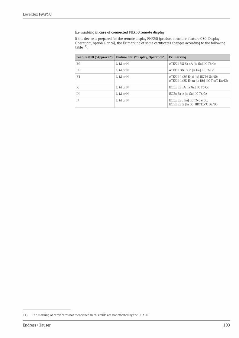
Levelflex FMP50
Endress+Hauser 103
Ex-marking in case of connected FHX50 remote display
If the device is prepared for the remote display FHX50 (product structure: feature 030: Display,Operation", option L or M), the Ex marking of some certificates changes according to the followingtable 11):
Feature 010 ("Approval") Feature 030 ("Display, Operation") Ex-marking
BG L, M or N ATEX II 3G Ex nA [ia Ga] IIC T6 Gc
BH L, M or N ATEX II 3G Ex ic [ia Ga] IIC T6 Gc
B3 L, M or N ATEX II 1/2G Ex d [ia] IIC T6 Ga/Gb,ATEX II 1/2D Ex ta [ia Db] IIIC Txx°C Da/Db
IG L, M or N IECEx Ex nA [ia Ga] IIC T6 Gc
IH L, M or N IECEx Ex ic [ia Ga] IIC T6 Gc
I3 L, M or N IECEx Ex d [ia] IIC T6 Ga/Gb,IECEx Ex ta [ia Db] IIIC Txx°C Da/Db
11) The marking of certificates not mentioned in this table are not affected by the FHX50.

www.addresses.endress.com
*71394741*71394741