operating instructions levelflex fmp51 modbus · operating instructions levelflex fmp51 modbus...
TRANSCRIPT
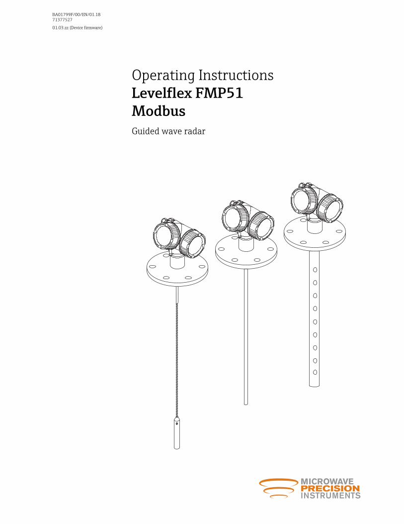
Operating InstructionsLevelflex FMP51ModbusGuided wave radar
BA01799F/00/EN/01.1871377527
01.03.zz (Device firmware)

Levelflex FMP51 Modbus Table of contents
3
Table of contents
1 Important document information . . . . 51.1 Document function . . . . . . . . . . . . . . . . . . . . . 51.2 Symbols . . . . . . . . . . . . . . . . . . . . . . . . . . . . . . 5
1.2.1 Safety symbols . . . . . . . . . . . . . . . . . . 51.2.2 Electrical symbols . . . . . . . . . . . . . . . . 51.2.3 Tool symbols . . . . . . . . . . . . . . . . . . . . 51.2.4 Symbols for
certain types of information . . . . . . . . . 61.2.5 Symbols in graphics . . . . . . . . . . . . . . . 61.2.6 Symbols at the device . . . . . . . . . . . . . 7
1.3 Supplementary documentation . . . . . . . . . . . . . 81.3.1 Safety Instructions (XA) . . . . . . . . . . . . 8
2 Basic safety instructions . . . . . . . . . . . . 92.1 Requirements for the personnel . . . . . . . . . . . . 92.2 Designated use . . . . . . . . . . . . . . . . . . . . . . . . 92.3 Workplace safety . . . . . . . . . . . . . . . . . . . . . . . 92.4 Operational safety . . . . . . . . . . . . . . . . . . . . . 102.5 Product safety . . . . . . . . . . . . . . . . . . . . . . . . 10
2.5.1 CE mark . . . . . . . . . . . . . . . . . . . . . . 102.5.2 EAC conformity . . . . . . . . . . . . . . . . . 10
3 Product description . . . . . . . . . . . . . . . . 113.1 Product design . . . . . . . . . . . . . . . . . . . . . . . . 11
3.1.1 Levelflex FMP51 . . . . . . . . . . . . . . . . 113.1.2 Electronics housing . . . . . . . . . . . . . . 12
3.2 Registered trademarks . . . . . . . . . . . . . . . . . . 13
4 Incoming acceptance and productidentification . . . . . . . . . . . . . . . . . . . . . 14
4.1 Incoming acceptance . . . . . . . . . . . . . . . . . . . 144.2 Product identification . . . . . . . . . . . . . . . . . . 14
4.2.1 Nameplate . . . . . . . . . . . . . . . . . . . . 15
5 Storage, Transport . . . . . . . . . . . . . . . . 165.1 Storage conditions . . . . . . . . . . . . . . . . . . . . . 165.2 Transport product to the measuring point . . . . 16
6 Mounting . . . . . . . . . . . . . . . . . . . . . . . . . 176.1 Mounting requirements . . . . . . . . . . . . . . . . . 17
6.1.1 Suitable mounting position . . . . . . . . 176.1.2 Applications with restricted
mounting space . . . . . . . . . . . . . . . . . 196.1.3 Notes on the mechanical load of the
probe . . . . . . . . . . . . . . . . . . . . . . . . 216.1.4 Notes on the process connection . . . . 236.1.5 Securing the probe . . . . . . . . . . . . . . 276.1.6 Special mounting conditions . . . . . . . 31
6.2 Mounting the device . . . . . . . . . . . . . . . . . . . 406.2.1 Required mounting tools . . . . . . . . . . 406.2.2 Shortening the probe . . . . . . . . . . . . . 40
6.2.3 Mounting the device . . . . . . . . . . . . . 426.2.4 Mounting the "Sensor remote"
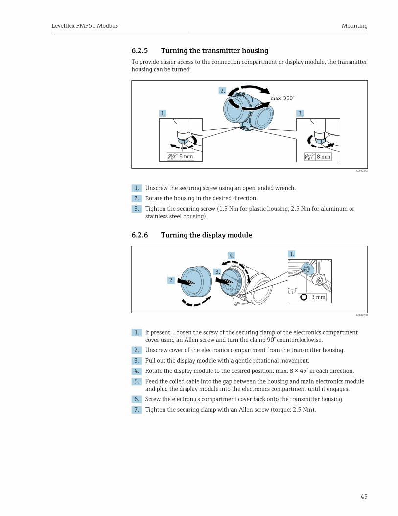
version . . . . . . . . . . . . . . . . . . . . . . . 436.2.5 Turning the transmitter housing . . . . 456.2.6 Turning the display module . . . . . . . . 45
6.3 Post-installation check . . . . . . . . . . . . . . . . . . 46
7 Electrical connection . . . . . . . . . . . . . . 477.1 Connection conditions . . . . . . . . . . . . . . . . . . 47
7.1.1 Terminal assignment . . . . . . . . . . . . . 477.1.2 Cable specification . . . . . . . . . . . . . . . 497.1.3 Device plug connectors . . . . . . . . . . . 507.1.4 Power supply . . . . . . . . . . . . . . . . . . 517.1.5 Overvoltage protection . . . . . . . . . . . 51
7.2 Connecting the measuring device . . . . . . . . . . 517.2.1 Plug-in spring-force terminals . . . . . . 52
7.3 Post-connection check . . . . . . . . . . . . . . . . . . 53
8 Operation options . . . . . . . . . . . . . . . . . 548.1 Overview . . . . . . . . . . . . . . . . . . . . . . . . . . . . 54
8.1.1 Local operation . . . . . . . . . . . . . . . . . 548.1.2 Operation with remote display and
operating module FHX50 . . . . . . . . . . 558.1.3 Remote operation . . . . . . . . . . . . . . . 55
8.2 Structure and function of the operatingmenu . . . . . . . . . . . . . . . . . . . . . . . . . . . . . . 578.2.1 Structure of the operating menu . . . . 578.2.2 User roles and related access
authorization . . . . . . . . . . . . . . . . . . 598.2.3 Write protection via access code . . . . . 608.2.4 Disabling write protection via access
code . . . . . . . . . . . . . . . . . . . . . . . . . 618.2.5 Deactivation of the write protection
via access code . . . . . . . . . . . . . . . . . 618.2.6 Write protection via write protection
switch . . . . . . . . . . . . . . . . . . . . . . . . 618.2.7 Enabling and disabling the keypad
lock . . . . . . . . . . . . . . . . . . . . . . . . . 638.3 Display and operating module . . . . . . . . . . . . 64
8.3.1 Display appearance . . . . . . . . . . . . . . 648.3.2 Operating elements . . . . . . . . . . . . . . 678.3.3 Entering numbers and text . . . . . . . . 688.3.4 Opening the context menu . . . . . . . . . 708.3.5 Envelope curve on the display and
operating module . . . . . . . . . . . . . . . 71
9 Commissioning via wizard . . . . . . . . . 72
10 Commissioning via operatingmenu . . . . . . . . . . . . . . . . . . . . . . . . . . . . . 73
10.1 Installation and function check . . . . . . . . . . . . 7310.2 Setting the operating language . . . . . . . . . . . . 7310.3 Configuration of a level measurement . . . . . . 74
Table of contents Levelflex FMP51 Modbus
4
10.4 Configuration of an interface measurement . . 7610.5 Recording the reference curve . . . . . . . . . . . . 7810.6 Configuration of the on-site display . . . . . . . . 79
10.6.1 Factory settings of the on-sitedisplay for level measurements . . . . . 79
10.6.2 Factory settings of the on-sitedisplay for interface measurements . . 79
10.6.3 Adjustment of the on-site display . . . 7910.7 Configuration of the Modbus
communication . . . . . . . . . . . . . . . . . . . . . . . 8010.7.1 Bus parameters . . . . . . . . . . . . . . . . . 8010.7.2 Device parameters . . . . . . . . . . . . . . . 8010.7.3 Process parameters . . . . . . . . . . . . . . 80
10.8 Configuration management . . . . . . . . . . . . . . 8110.9 Protection of the settings against
unauthorized changes . . . . . . . . . . . . . . . . . . 82
11 Diagnostics and troubleshooting . . . 8311.1 General trouble shooting . . . . . . . . . . . . . . . . 83
11.1.1 General errors . . . . . . . . . . . . . . . . . . 8311.1.2 Parametrization errors . . . . . . . . . . . 84
11.2 Diagnostic information on local display . . . . . . 8611.2.1 Diagnostic message . . . . . . . . . . . . . . 8611.2.2 Calling up remedial measures . . . . . . 88
11.3 Diagnostic event in the operating tool . . . . . . . 8911.4 Diagnostic list . . . . . . . . . . . . . . . . . . . . . . . . 9011.5 Event logbook . . . . . . . . . . . . . . . . . . . . . . . . 90
11.5.1 Event history . . . . . . . . . . . . . . . . . . . 9011.5.2 Filtering the event logbook . . . . . . . . 9111.5.3 Overview of information events . . . . . 91
11.6 Firmware history . . . . . . . . . . . . . . . . . . . . . . 93
12 Maintenance . . . . . . . . . . . . . . . . . . . . . . 9412.1 Exterior cleaning . . . . . . . . . . . . . . . . . . . . . . 94
13 Repairs . . . . . . . . . . . . . . . . . . . . . . . . . . . 9513.1 General information on repairs . . . . . . . . . . . . 95
13.1.1 Repairs to Ex-approved devices . . . . . 9513.1.2 Replacement of an electronics
module . . . . . . . . . . . . . . . . . . . . . . . 9513.1.3 Replacement of a device . . . . . . . . . . 95
13.2 Disposal . . . . . . . . . . . . . . . . . . . . . . . . . . . . 95
14 Accessories . . . . . . . . . . . . . . . . . . . . . . . 9614.1 Device-specific accessories . . . . . . . . . . . . . . . 96
14.1.1 Weather protection cover . . . . . . . . . 9614.1.2 Mounting bracket for the electronics
housing . . . . . . . . . . . . . . . . . . . . . . 9714.1.3 Mounting kit, isolated . . . . . . . . . . . . 9814.1.4 Centering star . . . . . . . . . . . . . . . . . . 9914.1.5 Remote display FHX50 . . . . . . . . . . 101
14.2 Communication-specific accessories . . . . . . . 10214.3 Service-specific accessories . . . . . . . . . . . . . . 10214.4 System components . . . . . . . . . . . . . . . . . . . 102
15 Operating menu . . . . . . . . . . . . . . . . . . 10315.1 Overview of the operating menu (display
module) . . . . . . . . . . . . . . . . . . . . . . . . . . . 10315.2 Overview of the operating menu (operating
tool) . . . . . . . . . . . . . . . . . . . . . . . . . . . . . . 11015.3 "Setup" menu . . . . . . . . . . . . . . . . . . . . . . . . 117
15.3.1 "Mapping" wizard . . . . . . . . . . . . . . . 13015.3.2 "Advanced setup" submenu . . . . . . . . 131
15.4 "Diagnostics" menu . . . . . . . . . . . . . . . . . . . . 18015.4.1 "Diagnostic list" submenu . . . . . . . . . 18215.4.2 "Event logbook" submenu . . . . . . . . . 18315.4.3 "Device information" submenu . . . . . 18415.4.4 "Measured values" submenu . . . . . . . 18715.4.5 "Data logging" submenu . . . . . . . . . . 19015.4.6 "Simulation" submenu . . . . . . . . . . . 19315.4.7 "Device check" submenu . . . . . . . . . . 197
15.5 Modbus register assignment . . . . . . . . . . . . 19915.5.1 Register table . . . . . . . . . . . . . . . . . 19915.5.2 Format of the diagnostic bytes . . . . . 20015.5.3 Format of the status bytes . . . . . . . . 201
Index . . . . . . . . . . . . . . . . . . . . . . . . . . . . . . . . . 202
Levelflex FMP51 Modbus Important document information
5
1 Important document information
1.1 Document functionThese Operating Instructions contain all the information that is required in various phasesof the life cycle of the device: from product identification, incoming acceptance andstorage, to mounting, connection, operation and commissioning through totroubleshooting, maintenance and disposal.
1.2 Symbols
1.2.1 Safety symbols
Symbol Meaning
DANGER
DANGER!This symbol alerts you to a dangerous situation. Failure to avoid this situation willresult in serious or fatal injury.
WARNING
WARNING!This symbol alerts you to a dangerous situation. Failure to avoid this situation canresult in serious or fatal injury.
CAUTION
CAUTION!This symbol alerts you to a dangerous situation. Failure to avoid this situation canresult in minor or medium injury.
NOTICE
NOTE!This symbol contains information on procedures and other facts which do not result inpersonal injury.
1.2.2 Electrical symbols
Symbol Meaning
Direct current
Alternating current
Direct current and alternating current
Ground connectionA grounded terminal which, as far as the operator is concerned, is grounded via agrounding system.
Protective Earth (PE)A terminal which must be connected to ground prior to establishing any otherconnections.
The ground terminals are situated inside and outside the device:• Inner ground terminal: Connects the protectiv earth to the mains supply.• Outer ground terminal: Connects the device to the plant grounding system.
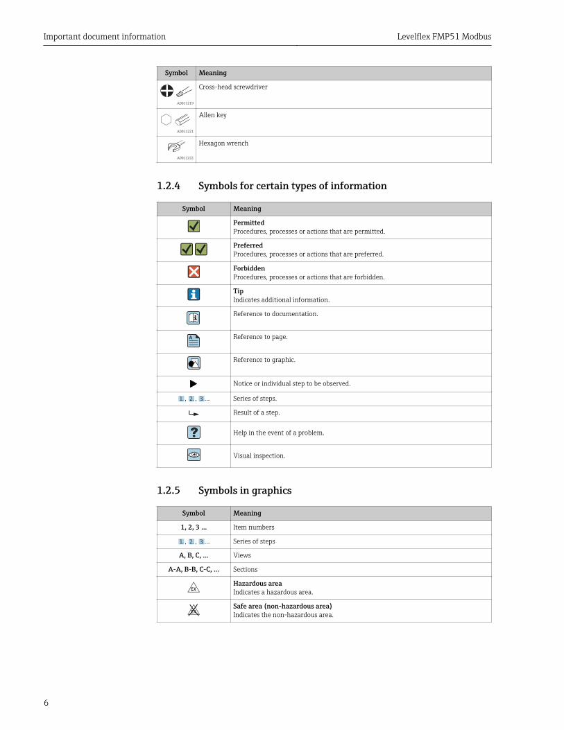
1.2.3 Tool symbols
Symbol Meaning
A0013442
Torx screwdriver
A0011220
Flat blade screwdriver
Important document information Levelflex FMP51 Modbus
6
Symbol Meaning
A0011219
Cross-head screwdriver
A0011221
Allen key
A0011222
Hexagon wrench
1.2.4 Symbols for certain types of information
Symbol Meaning
PermittedProcedures, processes or actions that are permitted.
PreferredProcedures, processes or actions that are preferred.
ForbiddenProcedures, processes or actions that are forbidden.
TipIndicates additional information.
Reference to documentation.
A Reference to page.
Reference to graphic.
Notice or individual step to be observed.
1. , 2. , 3.… Series of steps.
Result of a step.
Help in the event of a problem.
Visual inspection.
1.2.5 Symbols in graphics
Symbol Meaning
1, 2, 3 ... Item numbers
1. , 2. , 3.… Series of steps
A, B, C, ... Views
A-A, B-B, C-C, ... Sections
-Hazardous areaIndicates a hazardous area.
.Safe area (non-hazardous area)Indicates the non-hazardous area.

Levelflex FMP51 Modbus Important document information
7
1.2.6 Symbols at the device
Symbol Meaning
Safety instructionsObserve the safety instructions contained in the associated Operating Instructions.
Temperature resistance of the connection cablesSpecifies the minimum value of the temperature resistance of the connection cables.
Important document information Levelflex FMP51 Modbus
8
1.3 Supplementary documentation
Document Purpose and content of the document
Technical InformationTI01363F (FMP51)
Planning aid for your deviceThe document contains all the technical data on the device and providesan overview of the accessories and other products that can be ordered forthe device.
Brief Operating InstructionsKA01355F (FMP51)
Guide that takes you quickly to the 1st measured valueThe Brief Operating Instructions contain all the essential informationfrom incoming acceptance to initial commissioning.
Description of Device ParametersGP01126F (FMP51)
Reference for your parametersThe document provides a detailed explanation of each individualparameter in the operating menu. The description is aimed at those whowork with the device over the entire life cycle and perform specificconfigurations.
1.3.1 Safety Instructions (XA)Depending on the approval, the following Safety Instructions (XA) are supplied with thedevice. They are an integral part of the Operating Instructions.
Ordering feature 010 (Approval) Ordering feature 020 (Power Supply;Output)
Safety Instructions
Option Meaning Option Meaning
CC CSA C/US XP Cl. I, Div. 1, Groups A-D M 4-wire, Modbus RS485 XA01700F (inpreparation)
C3 CSA C/US XP Cl. I, II, III, Div. 1, Groups A-G; Class I, AEx d [ia] IIC/Ex d [ia] IIC; Class I, Div. 2, Groups A-D
M 4-wire, Modbus RS485 XA01700F (inpreparation)
Levelflex FMP51 Modbus Basic safety instructions
9
2 Basic safety instructions
2.1 Requirements for the personnelThe personnel for installation, commissioning, diagnostics and maintenance must fulfillthe following requirements:‣ Trained, qualified specialists must have a relevant qualification for this specific function
and task.‣ Are authorized by the plant owner/operator.‣ Are familiar with federal/national regulations.‣ Before starting work, read and understand the instructions in the manual and
supplementary documentation as well as the certificates (depending on theapplication).
‣ Follow instructions and comply with basic conditions.
The operating personnel must fulfill the following requirements:‣ Are instructed and authorized according to the requirements of the task by the facility's
owner-operator.‣ Follow the instructions in this manual.
2.2 Designated useApplication and measured materialsThe measuring device described in these Operating Instructions is intended only for leveland interface measurement of liquids. Depending on the version ordered the device canalso measure potentially explosive, flammable, poisonous and oxidizing materials.
Observing the limit values specified in the "Technical data" and listed in the OperatingInstructions and supplementary documentation, the measuring device may be used for thefollowing measurements only:‣ Measured process variable: Level and/or interface‣ Calculated process variable: Volume oder mass in arbitrarily shaped vessels (calculated
from the level by the linearization functionality)
To ensure that the measuring device remains in proper condition for the operation time:‣ Use the measuring device only for measured materials against which the process-
wetted materials are adequately resistant.‣ Observe the limit values in "Technical data".
Incorrect useThe manufacturer is not liable for damage caused by improper or non-designated use.
Residual riskThe electronics housing and its built-in components such as display module, mainelectronics module and I/O electronics module may heat to 80 °C (176 °F) during operationthrough heat transfer from the process as well as power dissipation within the electronics.During operation the sensor may assume a temperature near the temperature of themeasured material.
Danger of burns due to heated surfaces!‣ For high process temperatures: Install protection against contact in order to prevent
burns.
2.3 Workplace safetyFor work on and with the device:‣ Wear the required personal protective equipment according to federal/national
regulations.
Basic safety instructions Levelflex FMP51 Modbus
10
With divisible probe rods, medium may penetrate into the joints between the indivualparts of the rod. This medium may escape when loosening the joints. In the case ofdangerous (e.g. aggressive or toxic) media this may cause injuries.‣ When loosening the joints between the individual parts of the probe rod: Wear
appropriate protective equipment according to the medium.
2.4 Operational safetyRisk of injury.‣ Operate the device in proper technical condition and fail-safe condition only.‣ The operator is responsible for interference-free operation of the device.
Conversions to the deviceUnauthorized modifications to the device are not permitted and can lead to unforeseeabledangers.‣ If, despite this, modifications are required, consult with the manufacturer.
RepairTo ensure continued operational safety and reliability,‣ Carry out repairs on the device only if they are expressly permitted.‣ Observe federal/national regulations pertaining to repair of an electrical device.‣ Use original spare parts and accessories from the manufacturer only.
Hazardous areaTo eliminate a danger for persons or for the facility when the device is used in thehazardous area (e.g. explosion protection, pressure vessel safety):‣ Based on the nameplate, check whether the ordered device is permitted for the
intended use in the hazardous area.‣ Observe the specifications in the separate supplementary documentation that is an
integral part of these Instructions.
2.5 Product safetyThis measuring device is designed in accordance with good engineering practice to meetstate-of-the-art safety requirements, has been tested, and left the factory in a condition inwhich it is safe to operate. It meets general safety standards and legal requirements.
NOTICELoss of degree of protection by opening of the device in humid environments‣ If the device is opened in a humid environment, the degree of protection indicated on
the nameplate is no longer valid. This may also impair the safe operation of the device.
2.5.1 CE markThe measuring system meets the legal requirements of the applicable EC guidelines. Theseare listed in the corresponding EC Declaration of Conformity together with the standardsapplied.
The manufacturer confirms successful testing of the device by affixing to it the CE mark.
2.5.2 EAC conformityThe measuring system meets the legal requirements of the applicable EAC guidelines.These are listed in the corresponding EAC Declaration of Conformity together with thestandards applied.
The manufacturer confirms successful testing of the device by affixing to it the EAC mark.
Levelflex FMP51 Modbus Product description
11
3 Product description
3.1 Product design
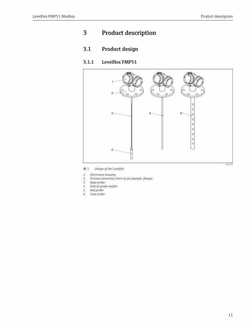
3.1.1 Levelflex FMP51
1
2
53
4
6
A0012399
1 Design of the Levelflex
1 Electronics housing2 Process connection (here as an example: flange)3 Rope probe4 End-of-probe weight5 Rod probe6 Coax probe
Product description Levelflex FMP51 Modbus
12
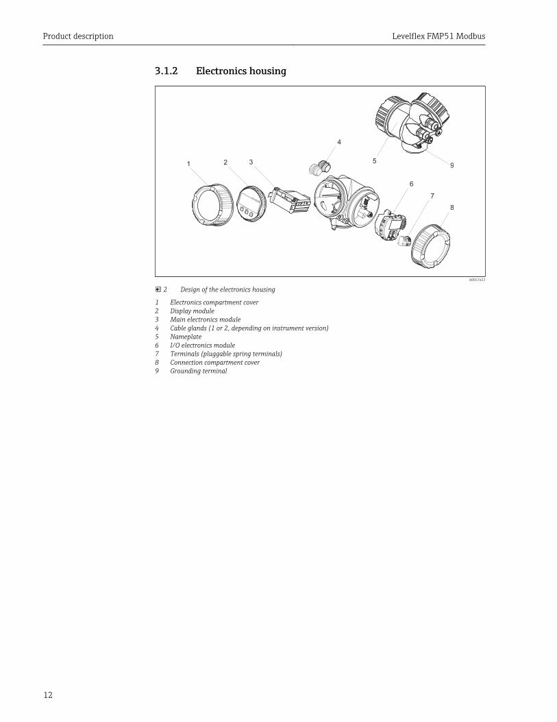
3.1.2 Electronics housing
Esc
–
+
E
1 2 3
4
5
6
9
7
8
A0012422
2 Design of the electronics housing
1 Electronics compartment cover2 Display module3 Main electronics module4 Cable glands (1 or 2, depending on instrument version)5 Nameplate6 I/O electronics module7 Terminals (pluggable spring terminals)8 Connection compartment cover9 Grounding terminal
Levelflex FMP51 Modbus Product description
13
3.2 Registered trademarksModbus®
Registered trademark of SCHNEIDER AUTOMATION, INC.
KALREZ®, VITON®
Registered trademark of DuPont Performance Elastomers L.L.C., Wilmington, USA
TEFLON®
Registered trademark of E.I. DuPont de Nemours & Co., Wilmington, USA
TRI CLAMP®
Registered trademark of Alfa Laval Inc., Kenosha, USA
NORD-LOCK®
Registered trademark of Nord-Lock International AB
FISHER®
Registered trademark of Fisher Controls International LLC, Marshalltown, USA
MASONEILAN®
Registered trademark of Dresser, Inc., Addison, USA
Incoming acceptance and product identification Levelflex FMP51 Modbus
14
4 Incoming acceptance and productidentification
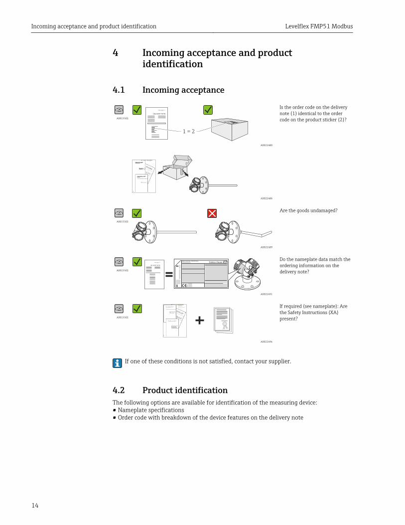
4.1 Incoming acceptance
A0015502
DELIVERY NOTE
1 = 2
A0022480
Is the order code on the deliverynote (1) identical to the ordercode on the product sticker (2)?
A0022486
A0015502
A0022489
Are the goods undamaged?
A0015502
DELIVERY NOTE
Made in Germany, 79689 Maulburg
A0022491
Do the nameplate data match theordering information on thedelivery note?
A0015502
A0022494
If required (see nameplate): Arethe Safety Instructions (XA)present?
If one of these conditions is not satisfied, contact your supplier.
4.2 Product identificationThe following options are available for identification of the measuring device:• Nameplate specifications• Order code with breakdown of the device features on the delivery note
Levelflex FMP51 Modbus Incoming acceptance and product identification
15
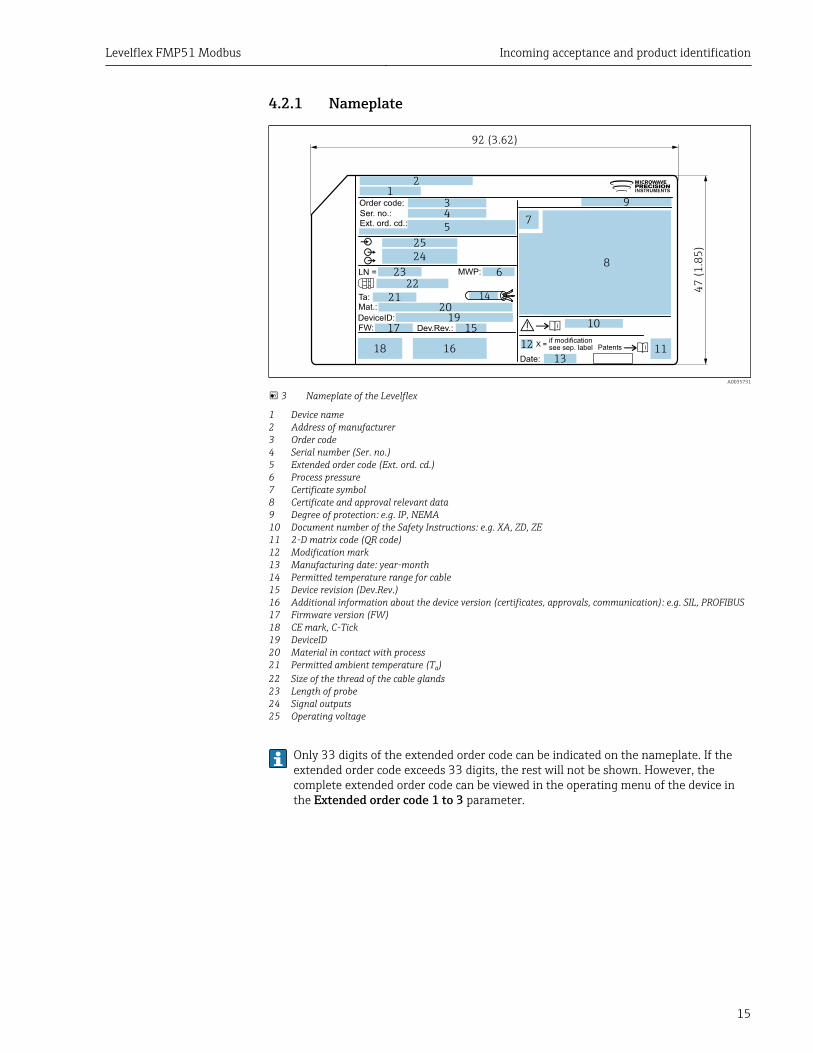
4.2.1 Nameplate
1920
21
23
24
22
25
12
34
5
6
7
8
9
18
17
16
15
14
13
Ext. ord. cd.:
Order code:Ser. no.:
LN =
Mat.:
Date:
FW: Dev.Rev.:DeviceID:
Ta:
if modificationsee sep. labelX =
MWP:
11
10
47
(1
.85
)
92 (3.62)
12
A0035731
3 Nameplate of the Levelflex
1 Device name2 Address of manufacturer3 Order code4 Serial number (Ser. no.)5 Extended order code (Ext. ord. cd.)6 Process pressure7 Certificate symbol8 Certificate and approval relevant data9 Degree of protection: e.g. IP, NEMA10 Document number of the Safety Instructions: e.g. XA, ZD, ZE11 2-D matrix code (QR code)12 Modification mark13 Manufacturing date: year-month14 Permitted temperature range for cable15 Device revision (Dev.Rev.)16 Additional information about the device version (certificates, approvals, communication): e.g. SIL, PROFIBUS17 Firmware version (FW)18 CE mark, C-Tick19 DeviceID20 Material in contact with process21 Permitted ambient temperature (Ta)22 Size of the thread of the cable glands23 Length of probe24 Signal outputs25 Operating voltage
Only 33 digits of the extended order code can be indicated on the nameplate. If theextended order code exceeds 33 digits, the rest will not be shown. However, thecomplete extended order code can be viewed in the operating menu of the device inthe Extended order code 1 to 3 parameter.
Storage, Transport Levelflex FMP51 Modbus
16
5 Storage, Transport
5.1 Storage conditions• Permitted storage temperature: –40 to +80 °C (–40 to +176 °F)• Use the original packaging.
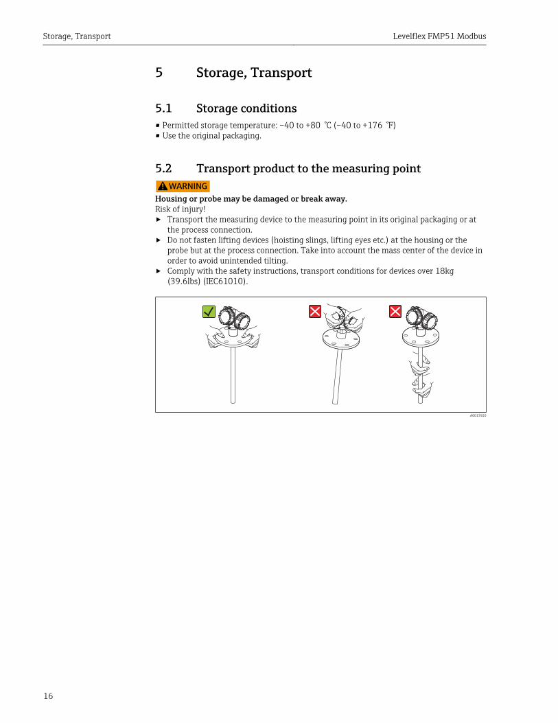
5.2 Transport product to the measuring pointLWARNING
Housing or probe may be damaged or break away.Risk of injury!‣ Transport the measuring device to the measuring point in its original packaging or at
the process connection.‣ Do not fasten lifting devices (hoisting slings, lifting eyes etc.) at the housing or the
probe but at the process connection. Take into account the mass center of the device inorder to avoid unintended tilting.
‣ Comply with the safety instructions, transport conditions for devices over 18kg(39.6lbs) (IEC61010).
A0013920
Levelflex FMP51 Modbus Mounting
17
6 Mounting
6.1 Mounting requirements
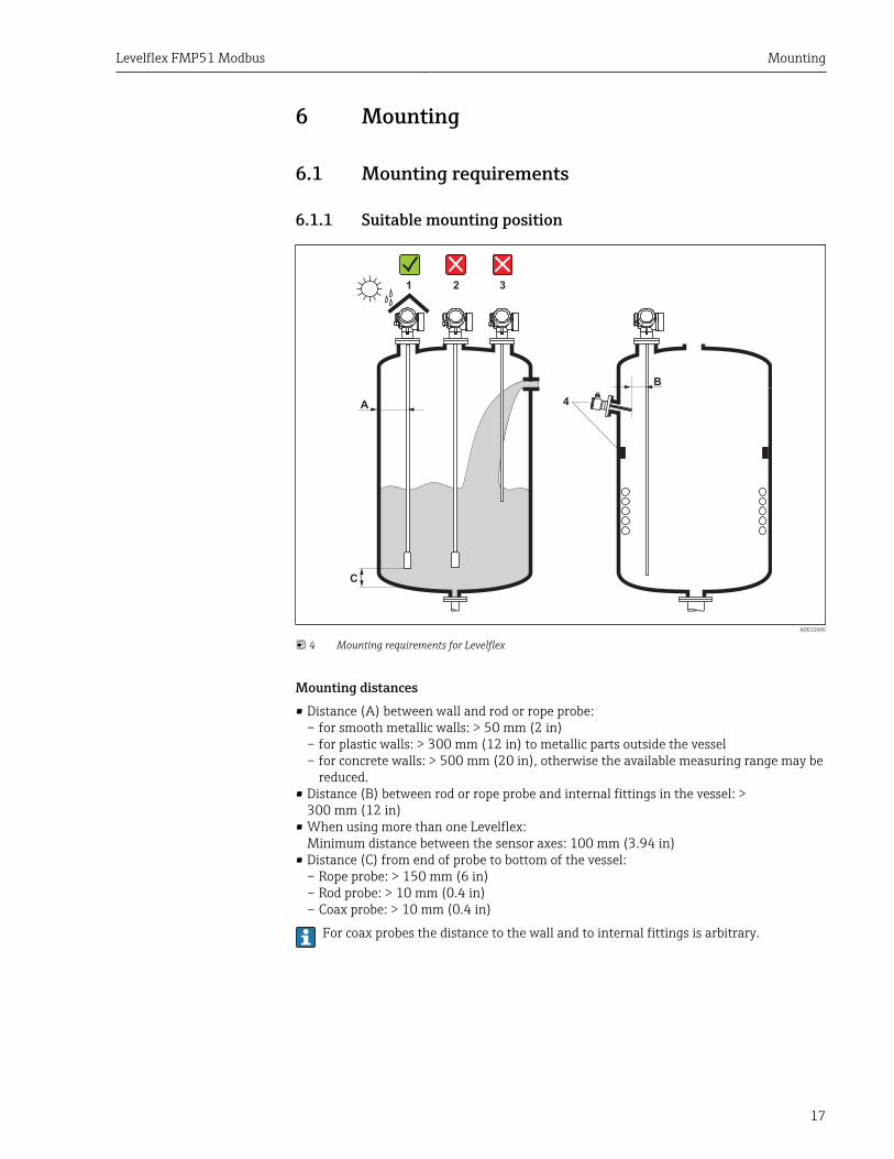
6.1.1 Suitable mounting position
A
C
1 2 3
4
B
A0012606
4 Mounting requirements for Levelflex
Mounting distances• Distance (A) between wall and rod or rope probe:
– for smooth metallic walls: > 50 mm (2 in)– for plastic walls: > 300 mm (12 in) to metallic parts outside the vessel– for concrete walls: > 500 mm (20 in), otherwise the available measuring range may be
reduced.• Distance (B) between rod or rope probe and internal fittings in the vessel: >
300 mm (12 in)• When using more than one Levelflex:
Minimum distance between the sensor axes: 100 mm (3.94 in)• Distance (C) from end of probe to bottom of the vessel:
– Rope probe: > 150 mm (6 in)– Rod probe: > 10 mm (0.4 in)– Coax probe: > 10 mm (0.4 in)
For coax probes the distance to the wall and to internal fittings is arbitrary.
Mounting Levelflex FMP51 Modbus
18
Additional conditions• When mounting in the open, a weather protection cover (1) may be installed to protect
the device against extreme weather conditions.• In metallic vessels: Preferably do not mount the probe in the center of the vessel (2), as
this would lead to increased interference echoes.If a central mounting position can not be avoided, it is crucial to perform an interferenceecho suppresion(mapping) after the commissioning of the device.
• Do not mount the probe in the filling curtain (3).• Avoid buckling the rope probe during installation or operation (e.g. through product
movement against silo wall) by selecting a suitable mounting location.
With suspended rope probes (probe end not fixed at the bottom) the distancebetween the probe rope and internal fittings in the tank must not fall below 300 mm(12") during the entire process. A sporadic contact between the probe weight and thecone of the vessel, however, does not influence the measurement as long as thedielectric constant of the medium is at least DC = 1.8.
When mounting the electronics housing into a recess (e.g. in a concrete ceiling),observe a minimum distance of 100 mm (4 inch) between the cover of the terminalcompartment / electronics compartment and the wall. Otherwise the connectioncompartment / electronics compartment is not accessible after installation.
Levelflex FMP51 Modbus Mounting
19
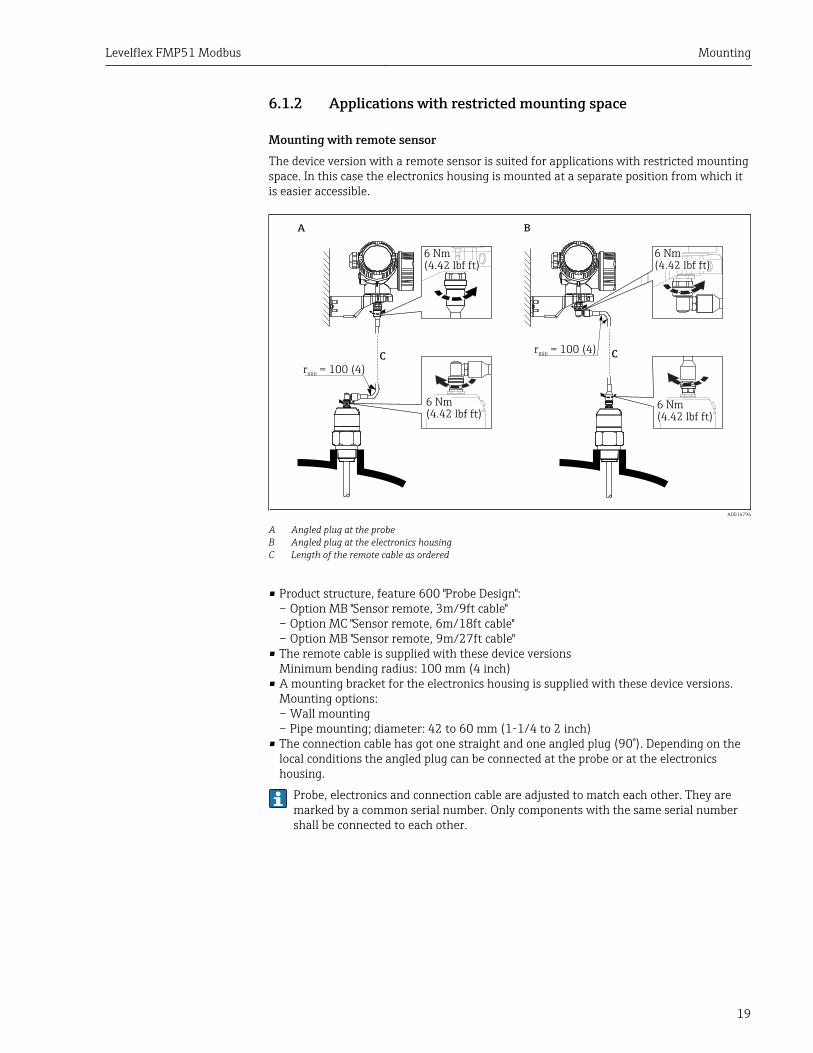
6.1.2 Applications with restricted mounting space
Mounting with remote sensorThe device version with a remote sensor is suited for applications with restricted mountingspace. In this case the electronics housing is mounted at a separate position from which itis easier accessible.
A B
C Cr = 100 (4)
min
r = 100 (4)min
6 Nm
(4.42 lbf ft)6 Nm
(4.42 lbf ft)
6 Nm
(4.42 lbf ft)
6 Nm
(4.42 lbf ft)
A0014794
A Angled plug at the probeB Angled plug at the electronics housingC Length of the remote cable as ordered
• Product structure, feature 600 "Probe Design":– Option MB "Sensor remote, 3m/9ft cable"– Option MC "Sensor remote, 6m/18ft cable"– Option MB "Sensor remote, 9m/27ft cable"
• The remote cable is supplied with these device versionsMinimum bending radius: 100 mm (4 inch)
• A mounting bracket for the electronics housing is supplied with these device versions.Mounting options:– Wall mounting– Pipe mounting; diameter: 42 to 60 mm (1-1/4 to 2 inch)
• The connection cable has got one straight and one angled plug (90°). Depending on thelocal conditions the angled plug can be connected at the probe or at the electronicshousing.
Probe, electronics and connection cable are adjusted to match each other. They aremarked by a common serial number. Only components with the same serial numbershall be connected to each other.
Mounting Levelflex FMP51 Modbus
20
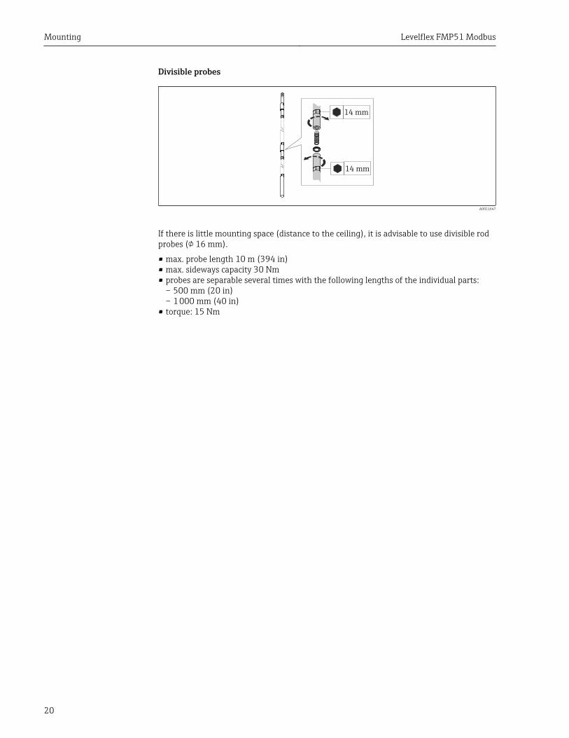
Divisible probes
14 mm
14 mm
A0021647
If there is little mounting space (distance to the ceiling), it is advisable to use divisible rodprobes ( 16 mm).
• max. probe length 10 m (394 in)• max. sideways capacity 30 Nm• probes are separable several times with the following lengths of the individual parts:
– 500 mm (20 in)– 1 000 mm (40 in)
• torque: 15 Nm
Levelflex FMP51 Modbus Mounting
21
6.1.3 Notes on the mechanical load of the probe
Tensile load limit of rope probes
Sensor Feature 060 Probe Tensile load limit [kN]
FMP51 LA, LBMB, MD
Rope 4mm (1/6") 316 5
Bending strength of rod probes
Sensor Feature 060 Probe Bending strength [Nm]
FMP51 AA, AB Rod 8mm (1/3") 316L 10
AC, AD Rod 12mm (1/2") 316L 30
AL, AM Rod 12mm (1/2") AlloyC 30
BA, BB, BC, BD Rod 16mm (0.63") 316L divisible 30
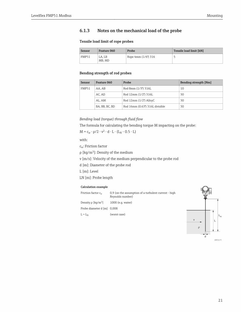
Bending load (torque) through fluid flow
The formula for calculating the bending torque M impacting on the probe:
M = cw ⋅ ρ/2 ⋅ v2 ⋅ d ⋅ L ⋅ (LN - 0.5 ⋅ L)
with:
cw: Friction factor
ρ [kg/m3]: Density of the medium
v [m/s]: Velocity of the medium perpendicular to the probe rod
d [m]: Diameter of the probe rod
L [m]: Level
LN [m]: Probe length
Calculation example
v
LN
L
d
A0014175
Friction factor cw 0,9 (on the assumption of a turbulent current - highReynolds number)
Density ρ [kg/m3] 1000 (e.g. water)
Probe diameter d [m] 0,008
L = LN (worst case)
Mounting Levelflex FMP51 Modbus
22
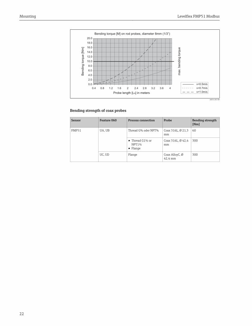
Bending�torque�[M]�on�rod�probes,�diameter�8mm�(1/3”)
Probe�length�[ ]�in�metersL N
v=0.5m/s
v=0.7m/s
v=1.0m/s
max.
�bendin
gto
rque
0.4 0.8 1.2 1.6 2 2.4 2.8 3.2 3.6 4
0.0
2.0
4.0
6.0
8.0
10.0
12.0
14.0
16.0
18.0
20.0
Be
nd
ing
[Nm
]to
rque
A0014182-EN
Bending strength of coax probes
Sensor Feature 060 Process connection Probe Bending strength[Nm]
FMP51 UA, UB Thread G¾ oder NPT¾ Coax 316L, Ø 21,3mm
60
• Thread G1½ orNPT1½
• Flange
Coax 316L, Ø 42,4mm
300
UC, UD Flange Coax AlloyC, Ø42,4 mm
300
Levelflex FMP51 Modbus Mounting
23
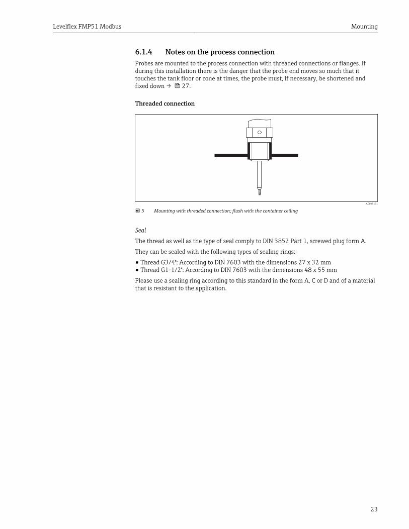
6.1.4 Notes on the process connectionProbes are mounted to the process connection with threaded connections or flanges. Ifduring this installation there is the danger that the probe end moves so much that ittouches the tank floor or cone at times, the probe must, if necessary, be shortened andfixed down → 27.
Threaded connection
A0015121
5 Mounting with threaded connection; flush with the container ceiling
Seal
The thread as well as the type of seal comply to DIN 3852 Part 1, screwed plug form A.
They can be sealed with the following types of sealing rings:
• Thread G3/4": According to DIN 7603 with the dimensions 27 x 32 mm• Thread G1-1/2": According to DIN 7603 with the dimensions 48 x 55 mm
Please use a sealing ring according to this standard in the form A, C or D and of a materialthat is resistant to the application.
Mounting Levelflex FMP51 Modbus
24
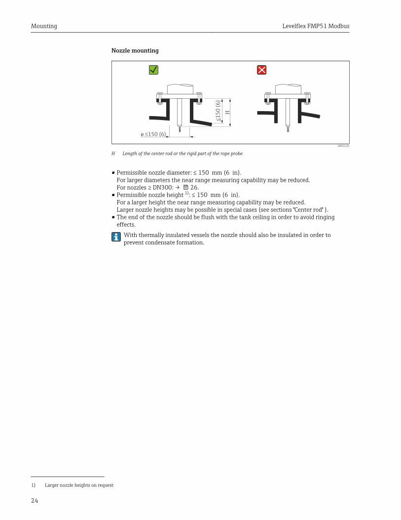
Nozzle mounting
!1
50
(6
)
H
ø 150 (6)!
A0015122
H Length of the center rod or the rigid part of the rope probe
• Permissible nozzle diameter: ≤ 150 mm (6 in).For larger diameters the near range measuring capability may be reduced.For nozzles ≥ DN300: → 26.
• Permissible nozzle height 1): ≤ 150 mm (6 in).For a larger height the near range measuring capability may be reduced.Larger nozzle heights may be possible in special cases (see sections "Center rod" ).
• The end of the nozzle should be flush with the tank ceiling in order to avoid ringingeffects.
With thermally insulated vessels the nozzle should also be insulated in order toprevent condensate formation.
1) Larger nozzle heights on request

Levelflex FMP51 Modbus Mounting
25
Center rod
For rope probes it may be necessary to use a version with center rod in order to prevent theprobe rod from coming into contact with the nozzle wall.
Probe Max. nozzle height (= length of the center rod) Option to be selected in feature 060 ("Probe")
FMP51 150 mm LA
6 inch LB
300 mm MB
12 inch MD
Mounting Levelflex FMP51 Modbus
26
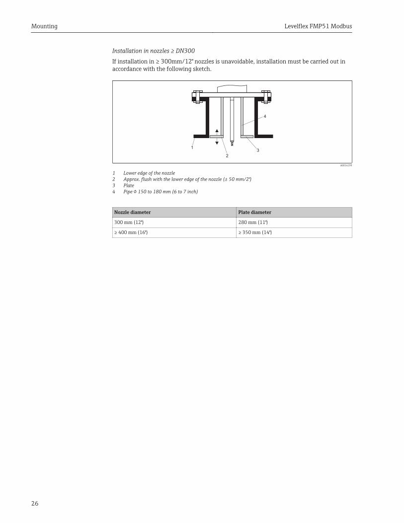
Installation in nozzles ≥ DN300
If installation in ≥ 300mm/12" nozzles is unavoidable, installation must be carried out inaccordance with the following sketch.
1
2
3
4
A0014199
1 Lower edge of the nozzle2 Approx. flush with the lower edge of the nozzle (± 50 mm/2")3 Plate4 Pipe 150 to 180 mm (6 to 7 inch)
Nozzle diameter Plate diameter
300 mm (12") 280 mm (11")
≥ 400 mm (16") ≥ 350 mm (14")
Levelflex FMP51 Modbus Mounting
27
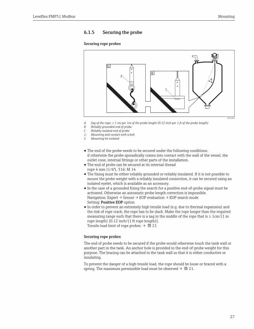
6.1.5 Securing the probe
Securing rope probes
1
A
C
B2
A0012609
A Sag of the rope: ≥ 1 cm per 1m of the probe length (0.12 inch per 1 ft of the probe length)B Reliably grounded end of probeC Reliably isolated end of probe1: Mounting and contact with a bolt2 Mounting kit isolated
• The end of the probe needs to be secured under the following conditions:if otherwise the probe sporadically comes into contact with the wall of the vessel, theoutlet cone, internal fittings or other parts of the installation.
• The end of probe can be secured at its internal threadrope 4 mm (1/6"), 316: M 14
• The fixing must be either reliably grounded or reliably insulated. If it is not possible tomount the probe weight with a reliably insulated connection, it can be secured using anisolated eyelet, which is available as an accessory.
• In the case of a grounded fixing the search for a positive end-of-probe signal must beactivated. Otherwise an automatic probe length correction is impossible.Navigation: Expert → Sensor → EOP evaluation → EOP search modeSetting: Positive EOP option
• In order to prevent an extremely high tensile load (e.g. due to thermal expansion) andthe risk of rope crack, the rope has to be slack. Make the rope longer than the requiredmeasuring range such that there is a sag in the middle of the rope that is ≥ 1cm/(1 mrope length) [0.12 inch/(1 ft rope length)].Tensile load limit of rope probes: → 21
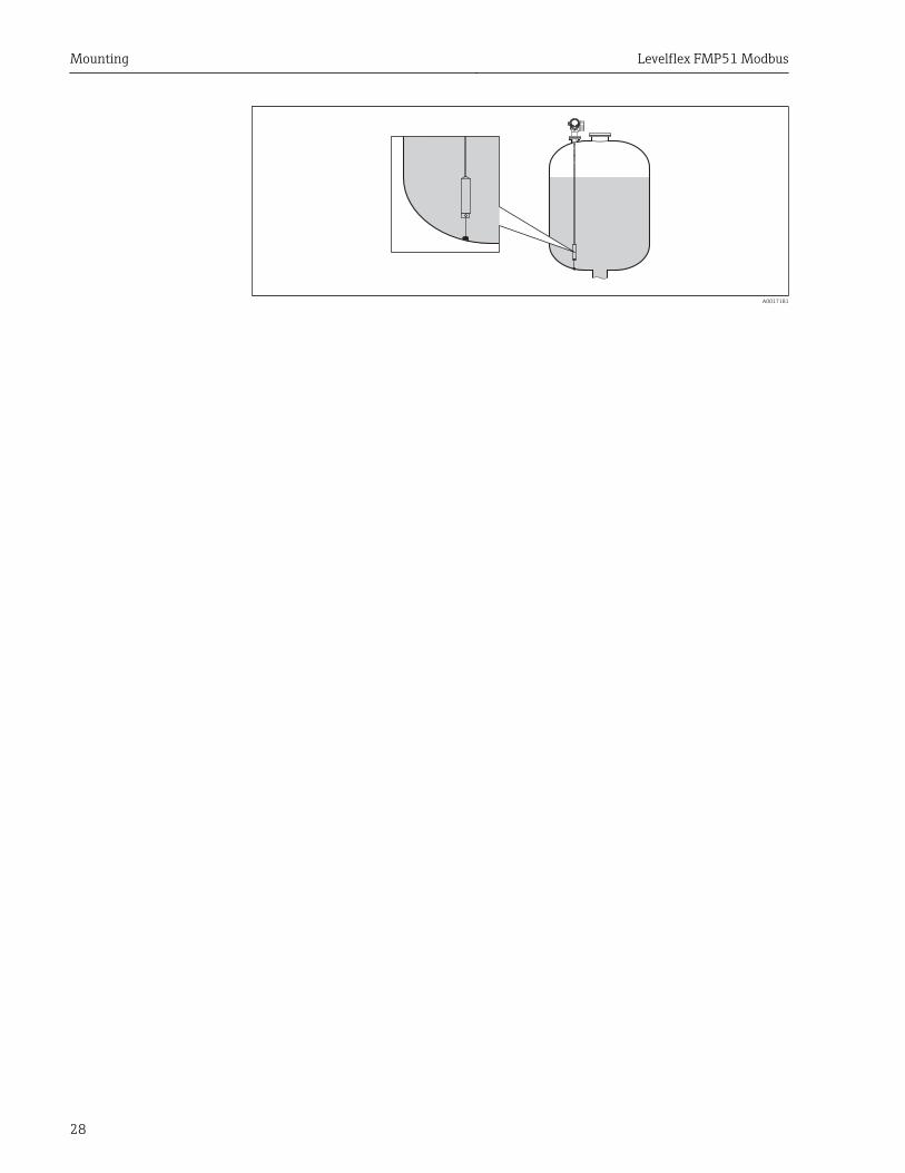
Securing rope probesThe end of probe needs to be secured if the probe would otherwise touch the tank wall oranother part in the tank. An anchor hole is provided in the end-of-probe weight for thispurpose. The bracing can be attached to the tank wall so that it is either conductive orinsulating.
To prevent the danger of a high tensile load, the rope should be loose or braced with aspring. The maximum permissible load must be observed → 21.
Mounting Levelflex FMP51 Modbus
28
A0017181
Levelflex FMP51 Modbus Mounting
29
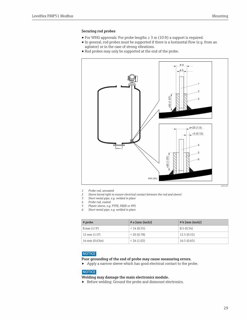
Securing rod probes• For WHG approvals: For probe lengths ≥ 3 m (10 ft) a support is required.• In general, rod probes must be supported if there is a horizontal flow (e.g. from an
agitator) or in the case of strong vibrations.• Rod probes may only be supported at the end of the probe.
mm (in)
ø a
ø b
!5
0 (
1.9
7)
1
2
3
!5
0 (
1.9
7)
4
5
6
ø<25 (1.0)
3 (0.12)!
A0012607
1 Probe rod, uncoated2 Sleeve bored tight to ensure electrical contact between the rod and sleeve!3 Short metal pipe, e.g. welded in place4 Probe rod, coated5 Plastic sleeve, e.g. PTFE, PEEK or PPS6 Short metal pipe, e.g. welded in place
probe a [mm (inch)] b [mm (inch)]
8 mm (1/3") < 14 (0.55) 8.5 (0.34)
12 mm (1/2") < 20 (0.78) 12.5 (0.52)
16 mm (0.63in) < 26 (1.02) 16.5 (0.65)
NOTICEPoor grounding of the end of probe may cause measuring errors.‣ Apply a narrow sleeve which has good electrical contact to the probe.
NOTICEWelding may damage the main electronics module.‣ Before welding: Ground the probe and dismount electronics.
Mounting Levelflex FMP51 Modbus
30
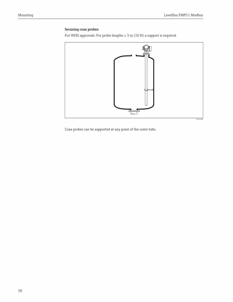
Securing coax probesFor WHG approvals: For probe lengths ≥ 3 m (10 ft) a support is required.
A0012608
Coax probes can be supported at any point of the outer tube.
Levelflex FMP51 Modbus Mounting
31
6.1.6 Special mounting conditions
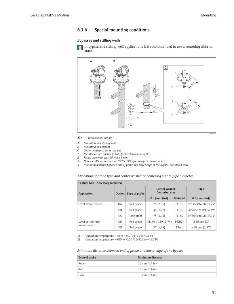
Bypasses and stilling wellsIn bypass and stilling well applications it is recommended to use a centering disks orstars.
A B
!1
00
(3.9
4)
øD
ød
ød
1
2
2
3
C
!1
00
(3.9
4)
4
A0012615
6 Dimensions: mm (in)
A Mounting in a stilling wellB Mounting in a bypassC Center washer or centering star1 Metallic center washer (316L) for level measurement2 Fixing screw; torque: 25 Nm ± 5 Nm3 Non-metallic centering star (PEEK, PFA) for interface measurement4 Minimum distance between end of probe and lower edge of the bypass; see table below
Allocation of probe type and center washer or centering star to pipe diameter
Feature 610 - Accessory mounted
Application Option Type of probeCenter washerCentering star
Pipe
d [mm (in)] Material D [mm (in)]
Level measurement OA Rod probe 75 (2,95) 316L DN80/3" to DN100/4"
OB Rod probe 45 (1,77) 316L DN50/2" to DN65/2½"
OC Rope probe 75 (2,95) 316L DN80/3" to DN100/4"
Level or interfacemeasurement
OD Rod probe 48...95 (1,89...3,74) PEEK 1) ≥ 50 mm (2")
OE Rod probe 37 (1,46) PFA 2) ≥ 40 mm (1.57")
1) Operation temperature: –60 to +250 °C (–76 to 482 °F)2) Operation temperature: –200 to +250 °C (–328 to +482 °F)
Minimum distance between end of probe and lower edge of the bypass
Type of probe Minimum distance
Rope 10 mm (0.4 in)
Rod 10 mm (0.4 in)
Coax 10 mm (0.4 in)
Mounting Levelflex FMP51 Modbus
32
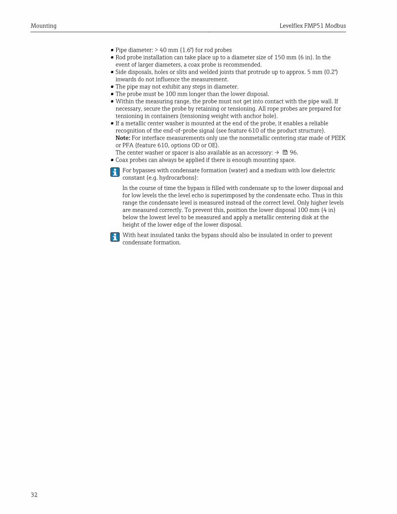
• Pipe diameter: > 40 mm (1.6") for rod probes• Rod probe installation can take place up to a diameter size of 150 mm (6 in). In the
event of larger diameters, a coax probe is recommended.• Side disposals, holes or slits and welded joints that protrude up to approx. 5 mm (0.2")
inwards do not influence the measurement.• The pipe may not exhibit any steps in diameter.• The probe must be 100 mm longer than the lower disposal.• Within the measuring range, the probe must not get into contact with the pipe wall. If
necessary, secure the probe by retaining or tensioning. All rope probes are prepared fortensioning in containers (tensioning weight with anchor hole).
• If a metallic center washer is mounted at the end of the probe, it enables a reliablerecognition of the end-of-probe signal (see feature 610 of the product structure).Note: For interface measurements only use the nonmetallic centering star made of PEEKor PFA (feature 610, options OD or OE).The center washer or spacer is also available as an accessory: → 96.
• Coax probes can always be applied if there is enough mounting space.
For bypasses with condensate formation (water) and a medium with low dielectricconstant (e.g. hydrocarbons):
In the course of time the bypass is filled with condensate up to the lower disposal andfor low levels the the level echo is superimposed by the condensate echo. Thus in thisrange the condensate level is measured instead of the correct level. Only higher levelsare measured correctly. To prevent this, position the lower disposal 100 mm (4 in)below the lowest level to be measured and apply a metallic centering disk at theheight of the lower edge of the lower disposal.
With heat insulated tanks the bypass should also be insulated in order to preventcondensate formation.
Levelflex FMP51 Modbus Mounting
33
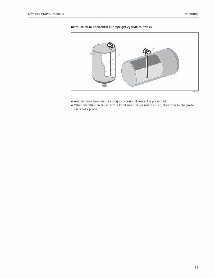
Installation in horizontal and upright cylindrical tanks
1
2
A0014141
• Any distance from wall, as long as occasional contact is prevented.• When installing in tanks with a lot of internals or internals situated close to the probe:
use a coax probe.
Mounting Levelflex FMP51 Modbus
34
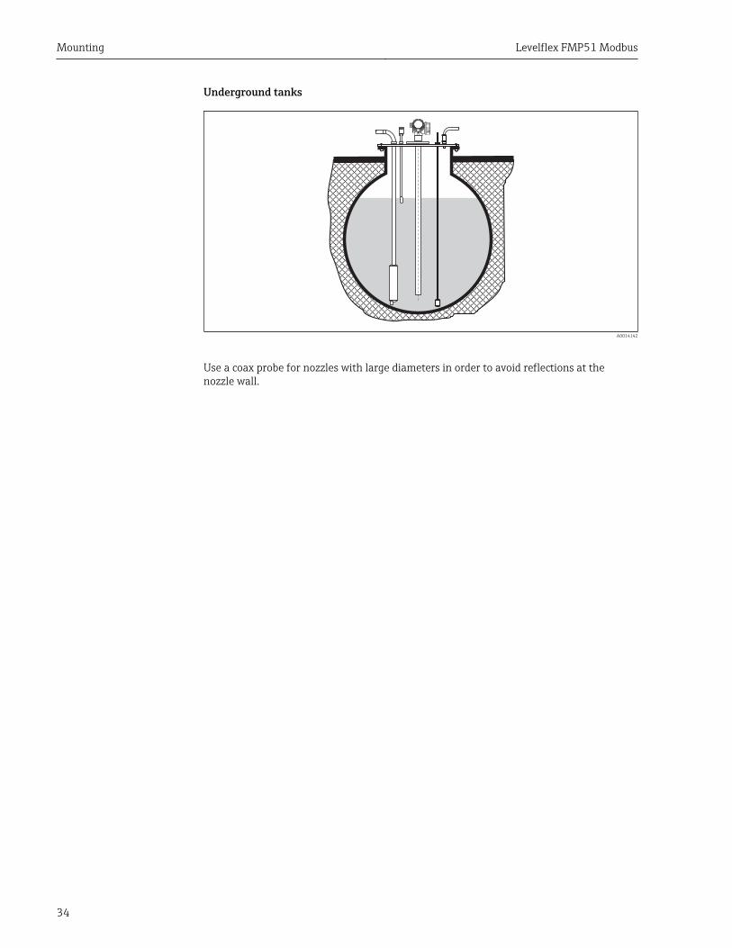
Underground tanks
A0014142
Use a coax probe for nozzles with large diameters in order to avoid reflections at thenozzle wall.
Levelflex FMP51 Modbus Mounting
35
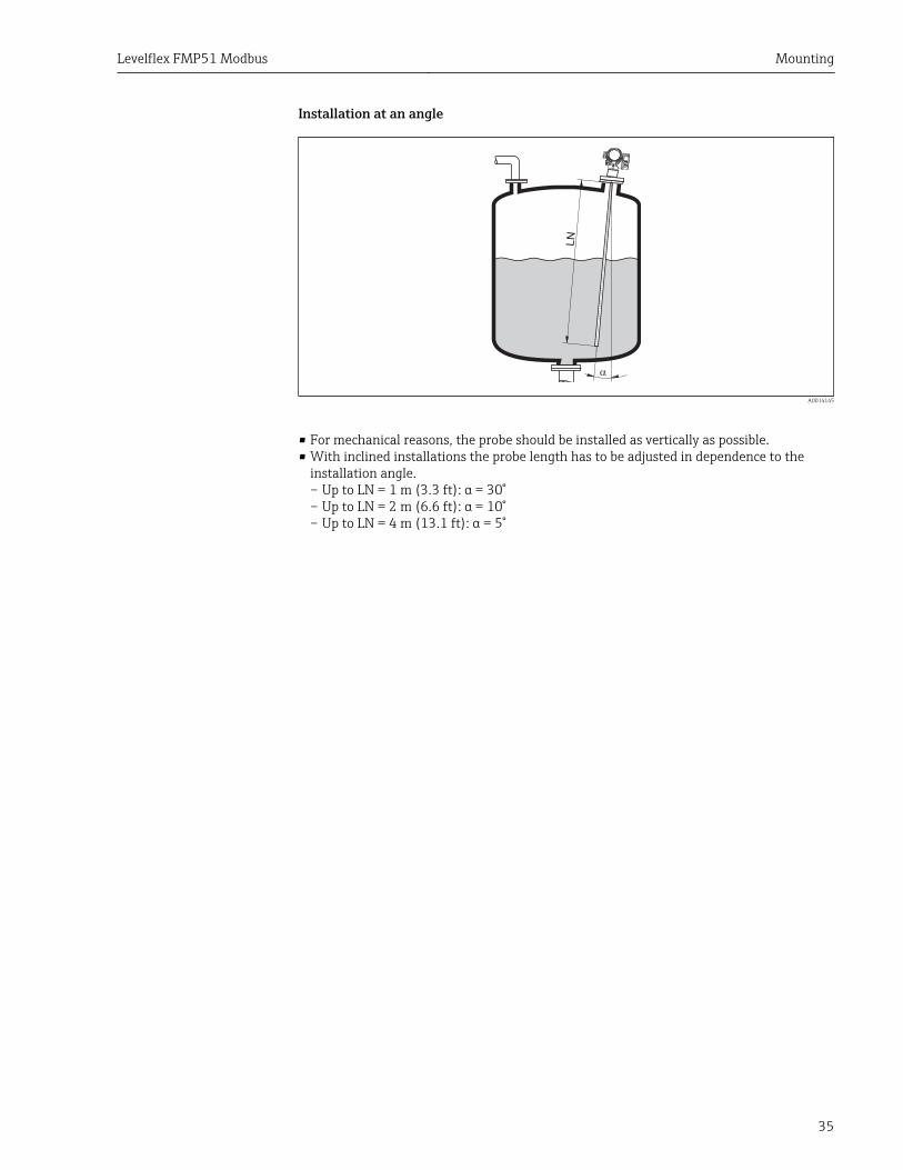
Installation at an angle
!
LN
A0014145
• For mechanical reasons, the probe should be installed as vertically as possible.• With inclined installations the probe length has to be adjusted in dependence to the
installation angle.– Up to LN = 1 m (3.3 ft): α = 30°– Up to LN = 2 m (6.6 ft): α = 10°– Up to LN = 4 m (13.1 ft): α = 5°
Mounting Levelflex FMP51 Modbus
36
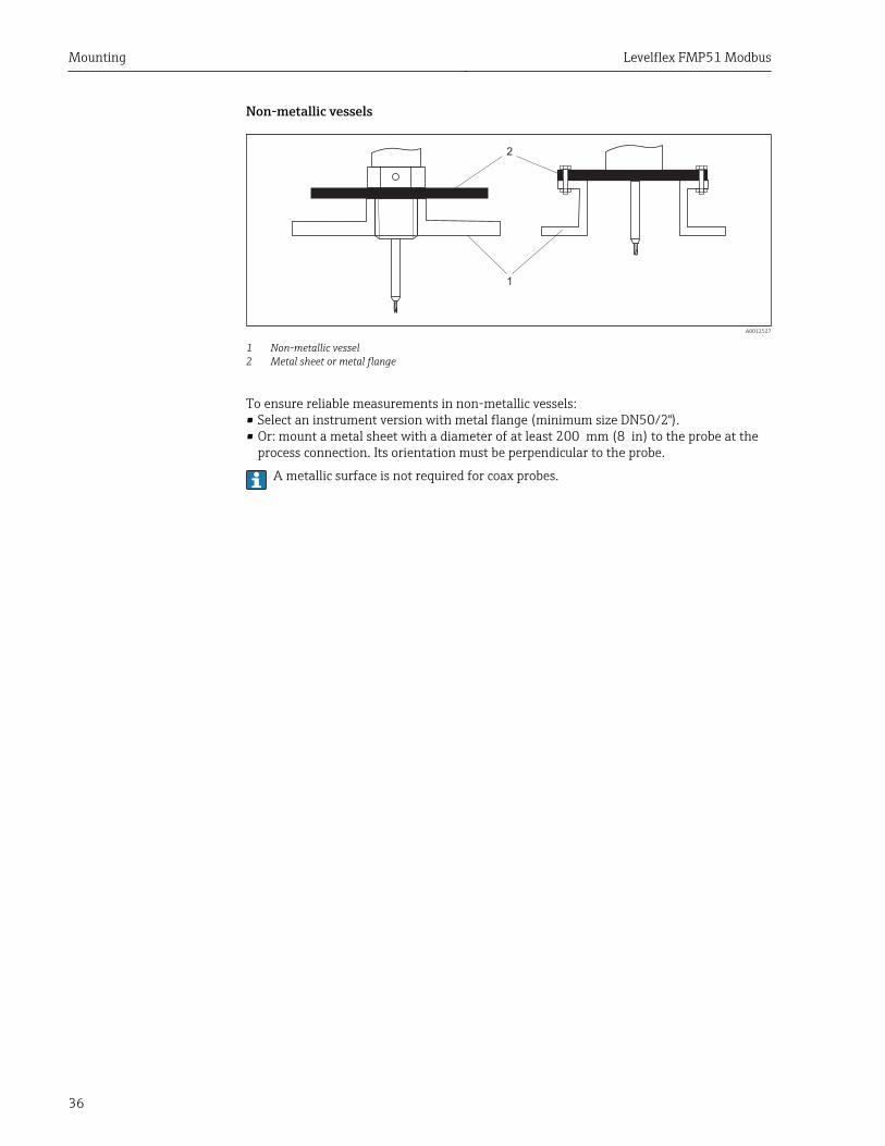
Non-metallic vessels
1
2
A0012527
1 Non-metallic vessel2 Metal sheet or metal flange
To ensure reliable measurements in non-metallic vessels:• Select an instrument version with metal flange (minimum size DN50/2").• Or: mount a metal sheet with a diameter of at least 200 mm (8 in) to the probe at the
process connection. Its orientation must be perpendicular to the probe.
A metallic surface is not required for coax probes.

Levelflex FMP51 Modbus Mounting
37
Plastic or glass tanks: Mounting the probe externally at the wall
1
2
a
3
A0014150
1 Plastic or glass tank2 Metall sheet with threaded sleeve3 No free space between tank wall and probe!
Requirements• The dielectric constant of the medium must be at least DC > 7.• The tank wall must be non-conductvie.• Maximum wall thickness (a):
– Plastic: < 15 mm (0.6")– Glass: < 10 mm (0.4")
• There may be no metallic reinforcements fixed to the tank.
Mounting conditions:• The probe must be mounted directly to the tank wall (no open space)• A plastic half pipe with a diameter of approx. 200 mm (8"), or some other protective
unit, must be affixed externally to the probe to prevent any influences on themeasurement.
• If the tank diameter is less than 300 mm (12"):A metallic grounding sheet must be installed at the opposite side of the tank. The sheetmust be conductively connected to the process connection and cover about the half ofthe vessel's circumference.
• If the tank diameter exceeds 300 mm (12"):A metal sheet with a diameter of at least 200 mm (8") must be mounted to the probe atthe process connection. Its orientation must be perpendicular to the probe (see above).
Calibration for external probe mounting
If the probe is mounted externally at the wall of the tank, the speed of signal propagationwill be reduced. There are two possibilities to compensate for this effect.
Compensation with the gas phase compensation factor
The effect of the dielectric wall can be compared to the effect of a dielectric gas phase.Thus it can be compensated for in the same manner. The compensation factor if given bythe quotient of the actual probe length LN and the probe length meausred when the tankis empty.
The device looks for the end of probe signal in the subtracted curve. Thus, the value ofthe measured probe length depends on the mapping. In order to obtain an exactvalue, it is advisable to determine the probe length manually using the envelope curvedisplay in FieldCare.
Mounting Levelflex FMP51 Modbus
38
Step Parameter Action
1 Expert → Sensor → Gas phase compensation → GPCmode
Select the Const. GPC factor option.
2 Expert → Sensor → Gas phase compensation → Const.GPC factor
Enter quotient: "(Actual probe length)/(Measuredprobe length)".
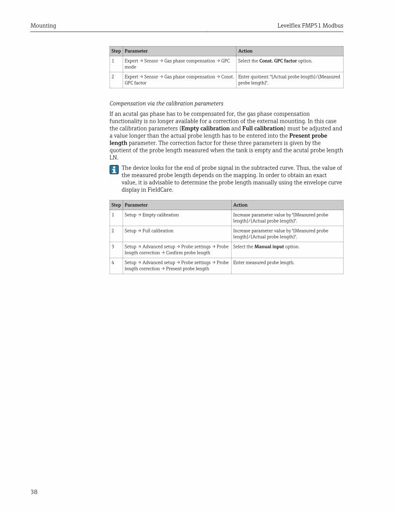
Compensation via the calibration parameters
If an acutal gas phase has to be compensated for, the gas phase compensationfunctionality is no longer available for a correction of the external mounting. In this casethe calibration parameters (Empty calibration and Full calibration) must be adjusted anda value longer than the actual probe length has to be entered into the Present probelength parameter. The correction factor for these three parameters is given by thequotient of the probe length measured when the tank is empty and the acutal probe lengthLN.
The device looks for the end of probe signal in the subtracted curve. Thus, the value ofthe measured probe length depends on the mapping. In order to obtain an exactvalue, it is advisable to determine the probe length manually using the envelope curvedisplay in FieldCare.
Step Parameter Action
1 Setup → Empty calibration Increase parameter value by "(Measured probelength)/(Actual probe length)".
2 Setup → Full calibration Increase parameter value by "(Measured probelength)/(Actual probe length)".
3 Setup → Advanced setup → Probe settings → Probelength correction → Confirm probe length
Select the Manual input option.
4 Setup → Advanced setup → Probe settings → Probelength correction → Present probe length
Enter measured probe length.
Levelflex FMP51 Modbus Mounting
39
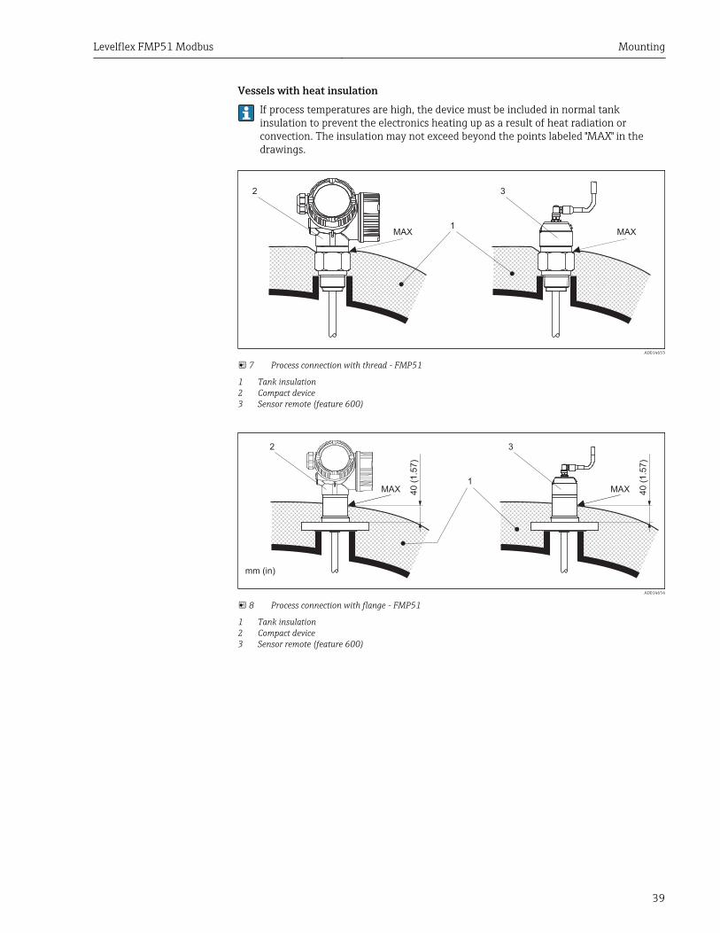
Vessels with heat insulationIf process temperatures are high, the device must be included in normal tankinsulation to prevent the electronics heating up as a result of heat radiation orconvection. The insulation may not exceed beyond the points labeled "MAX" in thedrawings.
MAX1
3
MAX
2
A0014653
7 Process connection with thread - FMP51
1 Tank insulation2 Compact device3 Sensor remote (feature 600)
40�(
1.5
7)
40�(
1.5
7)
MAX
mm�(in)
MAX1
32
A0014654
8 Process connection with flange - FMP51
1 Tank insulation2 Compact device3 Sensor remote (feature 600)
Mounting Levelflex FMP51 Modbus
40
6.2 Mounting the device
6.2.1 Required mounting tools• For mounting thread 3/4": Hexagonal wrench 36 mm• For mounting thread 1-1/2": Hexagonal wrench 55 mm• To shorten rod or coax probes: Saw• To shorten rope probes:
– Allen key AF 3 mm (for 4mm ropes) or AF 4 mm (for 6 mm ropes)– Saw or bolt cutter
• For flanges and other process connections: appropriate mounting tools• To turn the housing: Hexagonal wrench 8 mm
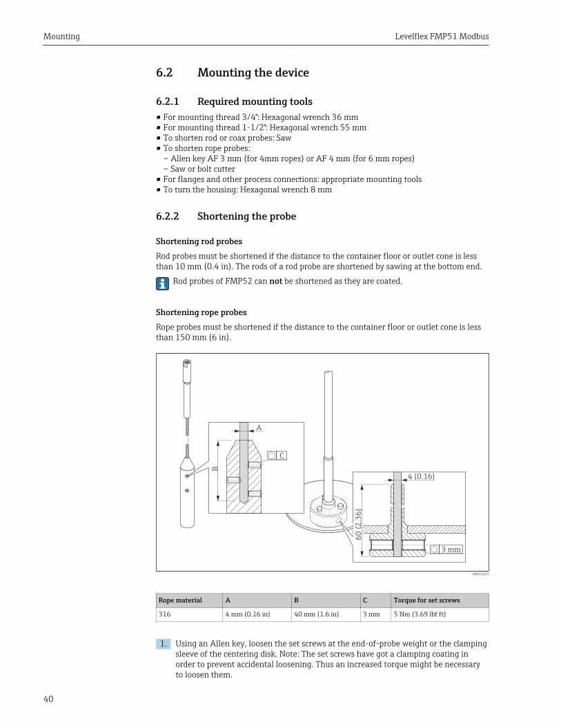
6.2.2 Shortening the probe
Shortening rod probesRod probes must be shortened if the distance to the container floor or outlet cone is lessthan 10 mm (0.4 in). The rods of a rod probe are shortened by sawing at the bottom end.
Rod probes of FMP52 can not be shortened as they are coated.
Shortening rope probesRope probes must be shortened if the distance to the container floor or outlet cone is lessthan 150 mm (6 in).
B
A
C
3 mm
4 (0.16)
60
(2
.36
)
A0012453
Rope material A B C Torque for set screws
316 4 mm (0.16 in) 40 mm (1.6 in) 3 mm 5 Nm (3.69 lbf ft)
1. Using an Allen key, loosen the set screws at the end-of-probe weight or the clampingsleeve of the centering disk. Note: The set screws have got a clamping coating inorder to prevent accidental loosening. Thus an increased torque might be necessaryto loosen them.
Levelflex FMP51 Modbus Mounting
41
2. Remove released rope from the weight or sleeve.
3. Measure off new rope length.
4. Wrap adhesive tape around the rope at the point to be shortened to prevent it fromfanning out.
5. Saw off the rope at a right angle or cut it off with a bolt cutter.
6. Insert the rope completely into the weight or sleeve.
7. Screw the set screws into place. Due to the clamping coating of the setscrewsapplication of a screw locking fluid is not necessary.
Shortening coax probesCoax probes must be shortened if the distance to the container floor or outlet cone is lessthan 10 mm (0.4 in).
Coax probes can be shortened max. 80 mm (3.2 in) from the end. They have centeringunits inside, which fix the rod centrally in the pipe. The centerings are held withborders on the rod. Shortening is possible up to approx. 10 mm (0.4 in) below thecentering unit.
The coax probe is shortened by sawing the pipe at the bottom end.
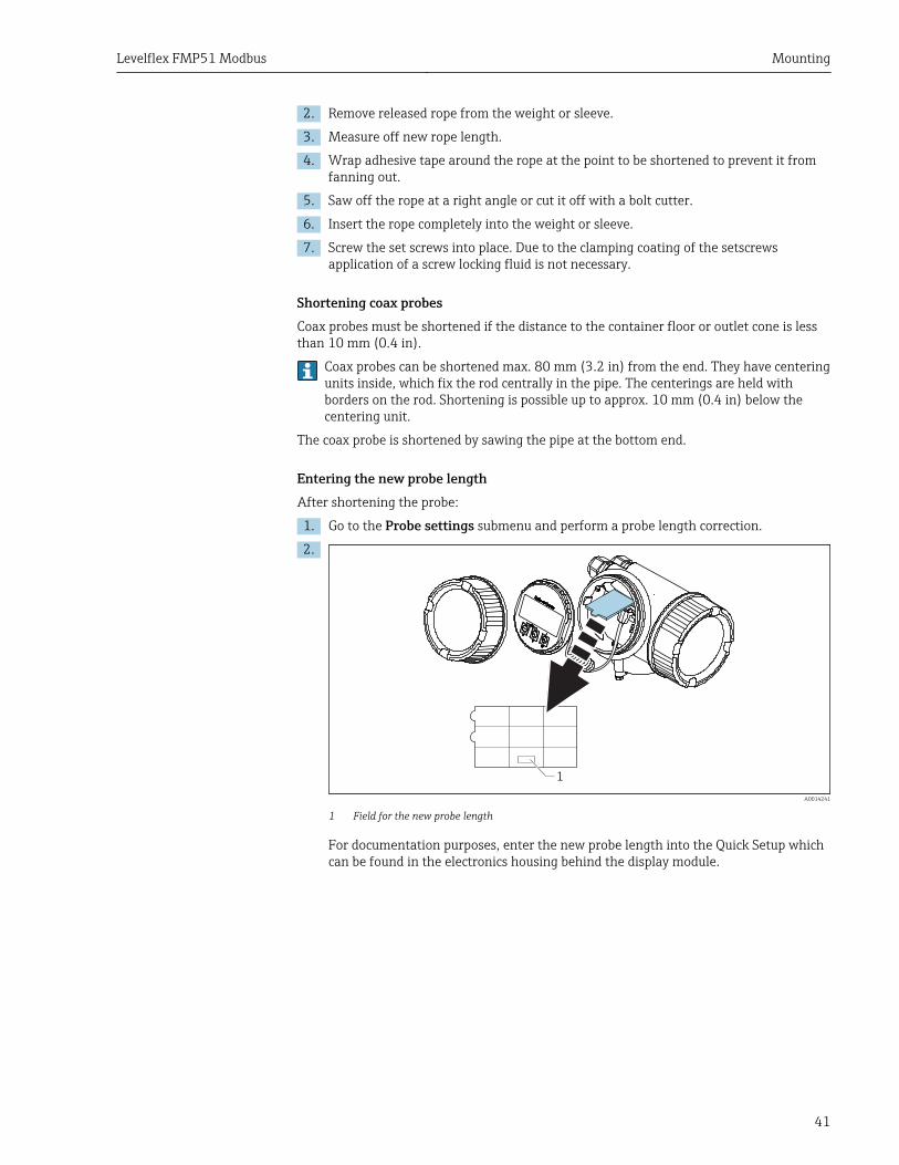
Entering the new probe lengthAfter shortening the probe:
1. Go to the Probe settings submenu and perform a probe length correction.
2.
1
A0014241
1 Field for the new probe length
For documentation purposes, enter the new probe length into the Quick Setup whichcan be found in the electronics housing behind the display module.
Mounting Levelflex FMP51 Modbus
42
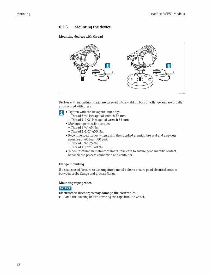
6.2.3 Mounting the device
Mounting devices with thread
A0012528
Devices with mounting thread are screwed into a welding boss or a flange and are usuallyalso secured with these.
• Tighten with the hexagonal nut only:– Thread 3/4": Hexagonal wrench 36 mm– Thread 1-1/2": Hexagonal wrench 55 mm
• Maximum permissible torque:– Thread 3/4": 45 Nm– Thread 1-1/2": 450 Nm
• Recommended torque when using the supplied aramid fibre seal and a processpressure of 40 bar (580 psi):– Thread 3/4": 25 Nm– Thread 1-1/2": 140 Nm
• When installing in metal containers, take care to ensure good metallic contactbetween the process connection and container.
Flange mountingIf a seal is used, be sure to use unpainted metal bolts to ensure good electrical contactbetween probe flange and process flange.
Mounting rope probesNOTICE
Electrostatic discharges may damage the electronics.‣ Earth the housing before lowering the rope into the vessel.
Levelflex FMP51 Modbus Mounting
43
*
A0012852
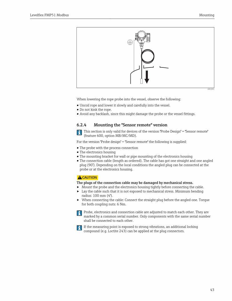
When lowering the rope probe into the vessel, observe the following:
• Uncoil rope and lower it slowly and carefully into the vessel.• Do not kink the rope.• Avoid any backlash, since this might damage the probe or the vessel fittings.
6.2.4 Mounting the "Sensor remote" versionThis section is only valid for devices of the version "Probe Design" = "Sensor remote"(feature 600, option MB/MC/MD).
For the version "Probe design" = "Sensor remote" the following is supplied:
• The probe with the process connection• The electronics housing• The mounting bracket for wall or pipe mounting of the electronics housing• The connection cable (length as ordered). The cable has got one straight and one angled
plug (90°). Depending on the local conditions the angled plug can be connected at theprobe or at the electronics housing.
LCAUTIONThe plugs of the connection cable may be damaged by mechanical stress.‣ Mount the probe and the electronics housing tightly before connecting the cable.‣ Lay the cable such that it is not exposed to mechanical stress. Minimum bending
radius: 100 mm (4").‣ When connecting the cable: Connect the straight plug before the angled one. Torque
for both coupling nuts: 6 Nm.
Probe, electronics and connection cable are adjusted to match each other. They aremarked by a common serial number. Only components with the same serial numbershall be connected to each other.
If the measuring point is exposed to strong vibrations, an additional lockingcompound (e.g. Loctite 243) can be applied at the plug connectors.
Mounting Levelflex FMP51 Modbus
44
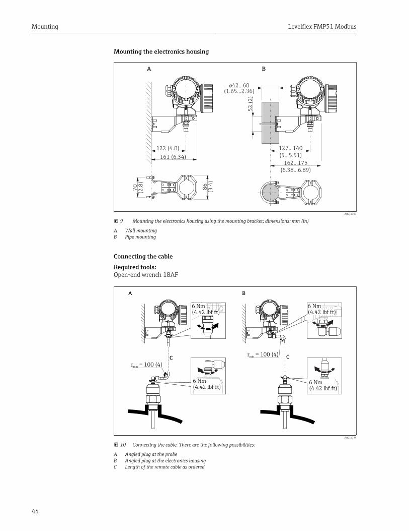
Mounting the electronics housing
122 (4.8)
52
(2
)
86
(3.4
)
70
(2.8
)
127...140
(5...5.51)161 (6.34)
162...175
(6.38...6.89)
A B
ø42...60
(1.65...2.36)
A0014793
9 Mounting the electronics housing using the mounting bracket; dimensions: mm (in)
A Wall mountingB Pipe mounting
Connecting the cableRequired tools:Open-end wrench 18AF
A B
C Cr = 100 (4)
min
r = 100 (4)min
6 Nm
(4.42 lbf ft)6 Nm
(4.42 lbf ft)
6 Nm
(4.42 lbf ft)
6 Nm
(4.42 lbf ft)
A0014794
10 Connecting the cable. There are the following possibilities:
A Angled plug at the probeB Angled plug at the electronics housingC Length of the remote cable as ordered
Levelflex FMP51 Modbus Mounting
45
6.2.5 Turning the transmitter housingTo provide easier access to the connection compartment or display module, the transmitterhousing can be turned:
max. 350°
8 mm 8 mm
1.
2.
3.
A0032242
1. Unscrew the securing screw using an open-ended wrench.
2. Rotate the housing in the desired direction.
3. Tighten the securing screw (1.5 Nm for plastic housing; 2.5 Nm for aluminum orstainless steel housing).
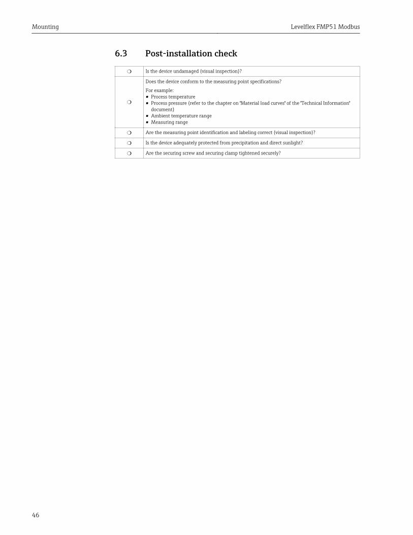
6.2.6 Turning the display module
+
E
–
1
3 mm
1.
2.
3.
4.
A0032238
1. If present: Loosen the screw of the securing clamp of the electronics compartmentcover using an Allen screw and turn the clamp 90° counterclockwise.
2. Unscrew cover of the electronics compartment from the transmitter housing.
3. Pull out the display module with a gentle rotational movement.
4. Rotate the display module to the desired position: max. 8 × 45° in each direction.
5. Feed the coiled cable into the gap between the housing and main electronics moduleand plug the display module into the electronics compartment until it engages.
6. Screw the electronics compartment cover back onto the transmitter housing.
7. Tighten the securing clamp with an Allen screw (torque: 2.5 Nm).
Mounting Levelflex FMP51 Modbus
46
6.3 Post-installation check
❍ Is the device undamaged (visual inspection)?
❍
Does the device conform to the measuring point specifications?
For example:• Process temperature• Process pressure (refer to the chapter on "Material load curves" of the "Technical Information"
document)• Ambient temperature range• Measuring range
❍ Are the measuring point identification and labeling correct (visual inspection)?
❍ Is the device adequately protected from precipitation and direct sunlight?
❍ Are the securing screw and securing clamp tightened securely?
Levelflex FMP51 Modbus Electrical connection
47
7 Electrical connection
7.1 Connection conditions
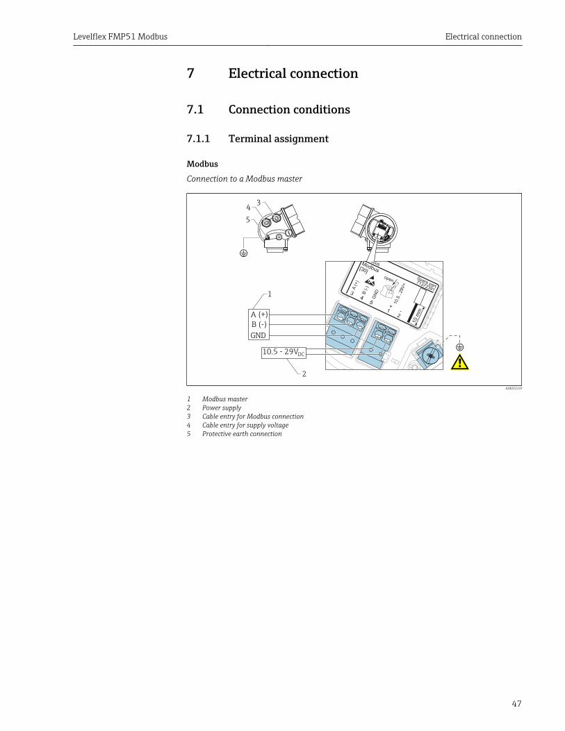
7.1.1 Terminal assignment
ModbusConnection to a Modbus master
open
Fieldbus
+ -
3
1 2
10.5
...2
9V
=
A(+
)
B (-)
GN
D
[30]
Modbus
4-wire
71372391
Spare part
45
1
2
10.5 - 29V
A (+)
B (-)
GND
DC
!
!
34
5
A0035159
1 Modbus master2 Power supply3 Cable entry for Modbus connection4 Cable entry for supply voltage5 Protective earth connection
Electrical connection Levelflex FMP51 Modbus
48
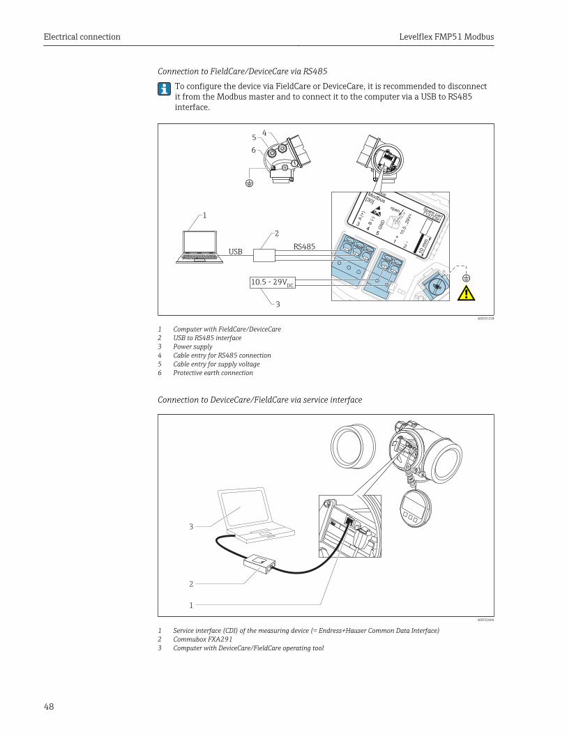
Connection to FieldCare/DeviceCare via RS485
To configure the device via FieldCare or DeviceCare, it is recommended to disconnectit from the Modbus master and to connect it to the computer via a USB to RS485interface.
open
Fieldbus
+ -
3
1 2
10.5
...2
9V
=
A(+
)
B (-)
GN
D
[30]
Modbus
4-wire
71372391
Spare part
452
3
45
1
!
6
10.5 - 29V
USBRS485
DC
!
A0035158
1 Computer with FieldCare/DeviceCare2 USB to RS485 interface3 Power supply4 Cable entry for RS485 connection5 Cable entry for supply voltage6 Protective earth connection
Connection to DeviceCare/FieldCare via service interface
1
2
3
A0032466
1 Service interface (CDI) of the measuring device (= Endress+Hauser Common Data Interface)2 Commubox FXA2913 Computer with DeviceCare/FieldCare operating tool

Levelflex FMP51 Modbus Electrical connection
49
7.1.2 Cable specification• Power line: Standard device cable• Modbus connection : A shielded cable is recommended. Observe grounding concept of
the plant.
Electrical connection Levelflex FMP51 Modbus
50
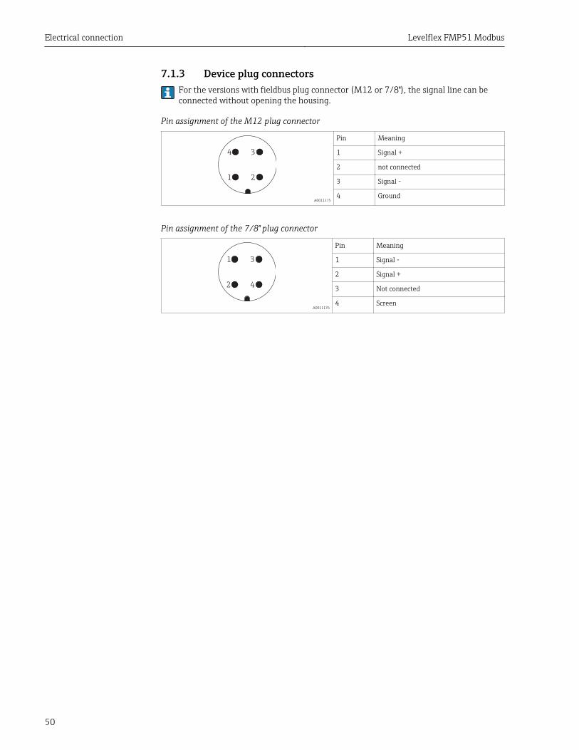
7.1.3 Device plug connectorsFor the versions with fieldbus plug connector (M12 or 7/8"), the signal line can beconnected without opening the housing.
Pin assignment of the M12 plug connector
21
34
A0011175
Pin Meaning
1 Signal +
2 not connected
3 Signal -
4 Ground
Pin assignment of the 7/8" plug connector
42
31
A0011176
Pin Meaning
1 Signal -
2 Signal +
3 Not connected
4 Screen
Levelflex FMP51 Modbus Electrical connection
51
7.1.4 Power supply
Supply voltage 10.5 to 29 VDC
Ripple 1 VSS (< 100 Hz); 10 mVSS (> 100 Hz)
7.1.5 Overvoltage protectionIf the measuring device is used for level measurement in flammable liquids which requiresthe use of overvoltage protection according to DIN EN 60079-14, standard fortest procedures 60060-1 (10 kA, pulse 8/20 μs), an overvoltage protection module has tobe installed.
External overvoltage protection moduleHAW562 or HAW569 from Endress+Hauser are suited as external overvoltage protection.
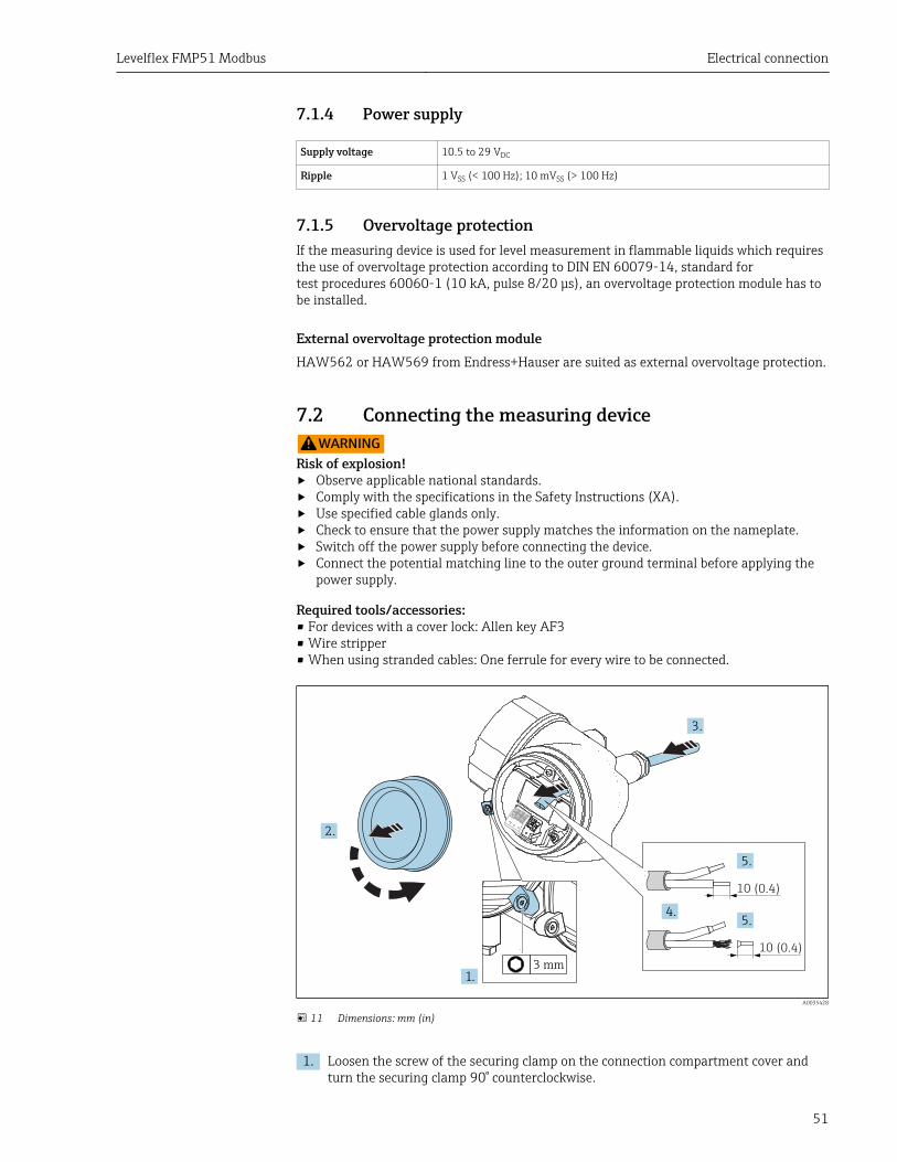
7.2 Connecting the measuring deviceLWARNING
Risk of explosion!‣ Observe applicable national standards.‣ Comply with the specifications in the Safety Instructions (XA).‣ Use specified cable glands only.‣ Check to ensure that the power supply matches the information on the nameplate.‣ Switch off the power supply before connecting the device.‣ Connect the potential matching line to the outer ground terminal before applying the
power supply.
Required tools/accessories:• For devices with a cover lock: Allen key AF3• Wire stripper• When using stranded cables: One ferrule for every wire to be connected.
2.
3.
1.
10 (0.4)
10 (0.4)
4.5.
5.
3 mm
A0035428
11 Dimensions: mm (in)
1. Loosen the screw of the securing clamp on the connection compartment cover andturn the securing clamp 90° counterclockwise.
Electrical connection Levelflex FMP51 Modbus
52
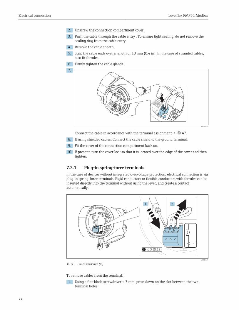
2. Unscrew the connection compartment cover.
3. Push the cable through the cable entry . To ensure tight sealing, do not remove thesealing ring from the cable entry.
4. Remove the cable sheath.
5. Strip the cable ends over a length of 10 mm (0.4 in). In the case of stranded cables,also fit ferrules.
6. Firmly tighten the cable glands.
7.
A0035426
Connect the cable in accordance with the terminal assignment → 47.
8. If using shielded cables: Connect the cable shield to the ground terminal.
9. Fit the cover of the connection compartment back on.
10. If present, turn the cover lock so that it is located over the edge of the cover and thentighten.
7.2.1 Plug-in spring-force terminalsIn the case of devices without integrated overvoltage protection, electrical connection is viaplug-in spring-force terminals. Rigid conductors or flexible conductors with ferrules can beinserted directly into the terminal without using the lever, and create a contactautomatically.
≤ 3 (0.12)
1. 2.
A0035427
12 Dimensions: mm (in)
To remove cables from the terminal:
1. Using a flat-blade screwdriver ≤ 3 mm, press down on the slot between the twoterminal holes
Levelflex FMP51 Modbus Electrical connection
53
2. while simultaneously pulling the cable end out of the terminal.
7.3 Post-connection check
Is the device or cable undamaged (visual check)?
Do the cables comply with the requirements ?
Do the cables have adequate strain relief?
Are all cable glands installed, securely tightened and leak-tight?
Does the supply voltage match the specifications on the nameplate?
Is the terminal assignment correct → 47?
If required: Has protective ground connection been established ?
If supply voltage is present, is the device ready for operation and do values appear on the displaymodule?
Are all housing covers installed and securely tightened?
Is the securing clamp tightened correctly?
Operation options Levelflex FMP51 Modbus
54
8 Operation options
8.1 Overview
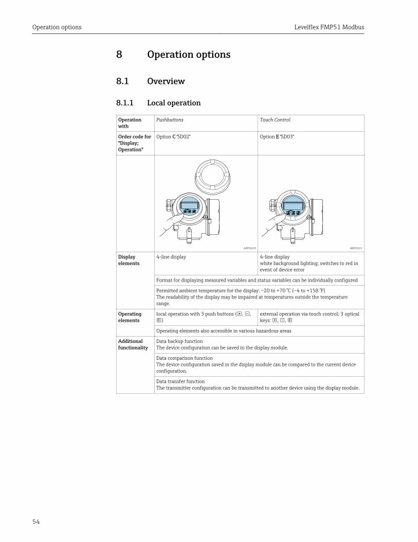
8.1.1 Local operation
Operationwith
Pushbuttons Touch Control
Order code for"Display;Operation"
Option C "SD02" Option E "SD03"
A0032219 A0032221
Displayelements
4-line display 4-line displaywhite background lighting; switches to red inevent of device error
Format for displaying measured variables and status variables can be individually configured
Permitted ambient temperature for the display: –20 to +70 °C (–4 to +158 °F)The readability of the display may be impaired at temperatures outside the temperaturerange.
Operatingelements
local operation with 3 push buttons ( , ,)
external operation via touch control; 3 opticalkeys: , ,
Operating elements also accessible in various hazardous areas
Additionalfunctionality
Data backup functionThe device configuration can be saved in the display module.
Data comparison functionThe device configuration saved in the display module can be compared to the current deviceconfiguration.
Data transfer functionThe transmitter configuration can be transmitted to another device using the display module.
Levelflex FMP51 Modbus Operation options
55
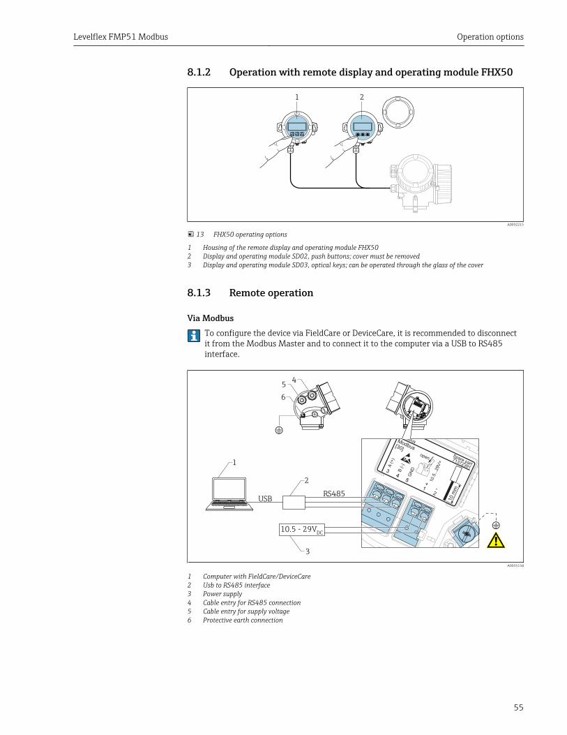
8.1.2 Operation with remote display and operating module FHX50
1 2
A0032215
13 FHX50 operating options
1 Housing of the remote display and operating module FHX502 Display and operating module SD02, push buttons; cover must be removed3 Display and operating module SD03, optical keys; can be operated through the glass of the cover
8.1.3 Remote operation
Via ModbusTo configure the device via FieldCare or DeviceCare, it is recommended to disconnectit from the Modbus Master and to connect it to the computer via a USB to RS485interface.
open
Fieldbus
+ -
3
1 2
10.5
...2
9V
=
A(+
)
B (-)
GN
D
[30]
Modbus
4-wire
71372391
Spare part
452
3
45
1
!
6
10.5 - 29V
USBRS485
DC
!
A0035158
1 Computer with FieldCare/DeviceCare2 Usb to RS485 interface3 Power supply4 Cable entry for RS485 connection5 Cable entry for supply voltage6 Protective earth connection
Operation options Levelflex FMP51 Modbus
56
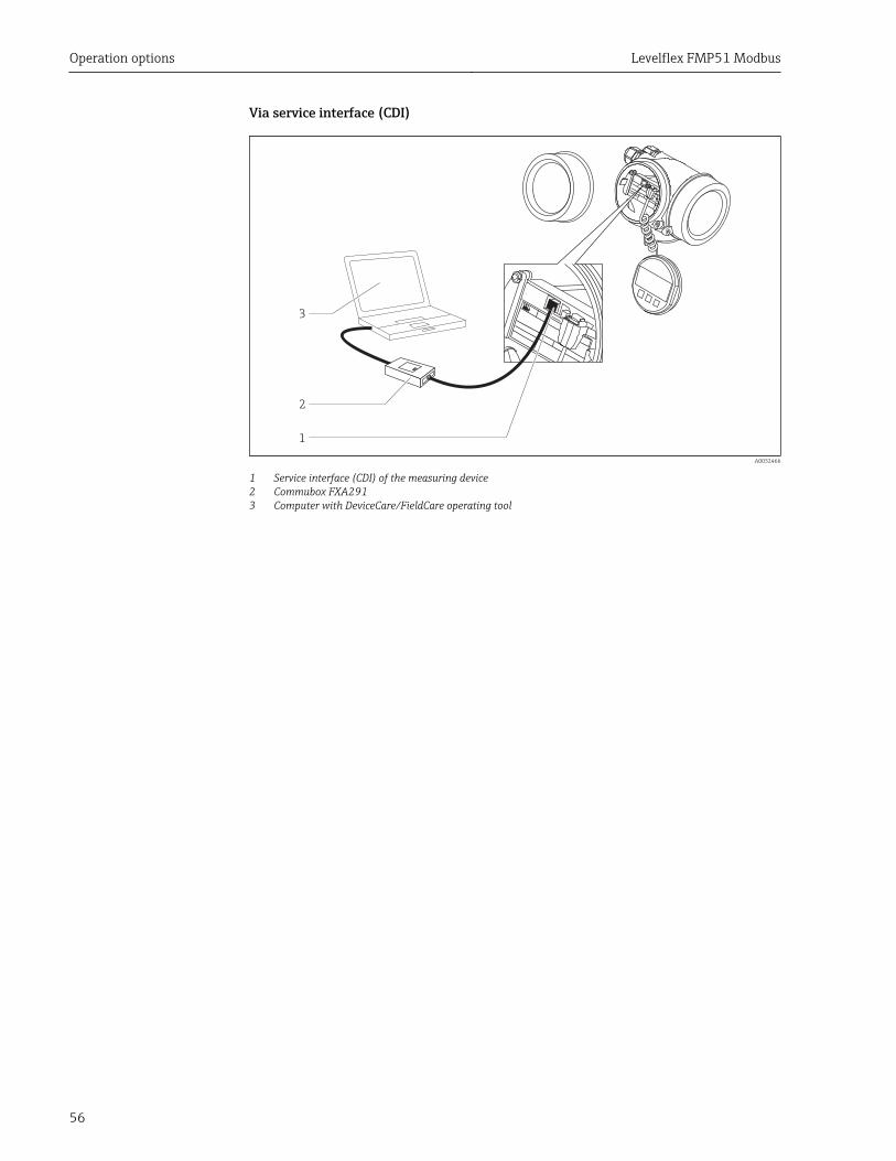
Via service interface (CDI)
1
2
3
A0032466
1 Service interface (CDI) of the measuring device2 Commubox FXA2913 Computer with DeviceCare/FieldCare operating tool
Levelflex FMP51 Modbus Operation options
57
8.2 Structure and function of the operating menu
8.2.1 Structure of the operating menu
Menu Submenu /parameter
Meaning
Language 1) Defines the operating language of the on-site display
Commissioning 2) Launches the interactive wizard forguided commissioning.Additional settings generally do not needto be made in the other menus when thewizard is finished.
Setup Parameter 1...Parameter N
Once values have been set for theseparameters, the measurement shouldgenerally be completely configured.
Advanced setup Contains additional submenus andparameters:• to adapt the device to special
measuring conditions.• to process the measured value (scaling,
linearization).• to configure the signal output.
Diagnostics Diagnostic list Contains up to 5 currently active errormessages.
Event logbook 3) Contains the last 20 messages (which areno longer active).
Device information Contains information for identifying thedevice.
Measured values Contains all current measured values.
Data logging Contains the history of the individualmeasuring values.
Simulation Is used to simulate measured values oroutput values.
Device check Contains all parameters needed to checkthe measurement capability of the device.
Heartbeat 4) Contains all the wizards for theHeartbeat Verification and HeartbeatMonitoring application packages.
Expert 5)
Contains all parameters of the device(including those that are already in one ofthe other menus). This menu is organizedaccording to the function blocks of the device.
The parameters of the Expert menu aredescribed in:GP01126F (Modbus)
System Contains all higher-order deviceparameters that do not concern themeasurement or measured valuecommunication.
Sensor Contains all parameters needed toconfigure the measurement.
Output Contains all parameters needed toconfigure the switch output (PFS).
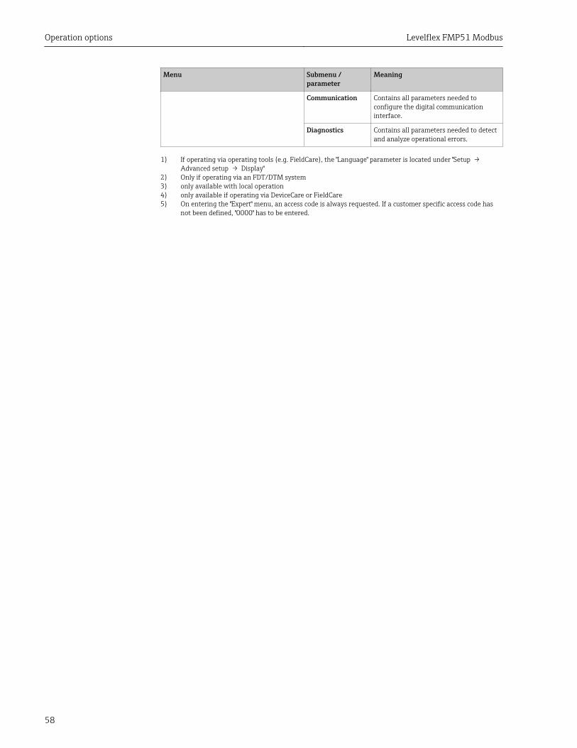
Operation options Levelflex FMP51 Modbus
58
Menu Submenu /parameter
Meaning
Communication Contains all parameters needed toconfigure the digital communicationinterface.
Diagnostics Contains all parameters needed to detectand analyze operational errors.
1) If operating via operating tools (e.g. FieldCare), the "Language" parameter is located under "Setup → Advanced setup → Display"
2) Only if operating via an FDT/DTM system3) only available with local operation4) only available if operating via DeviceCare or FieldCare5) On entering the "Expert" menu, an access code is always requested. If a customer specific access code has
not been defined, "0000" has to be entered.
Levelflex FMP51 Modbus Operation options
59
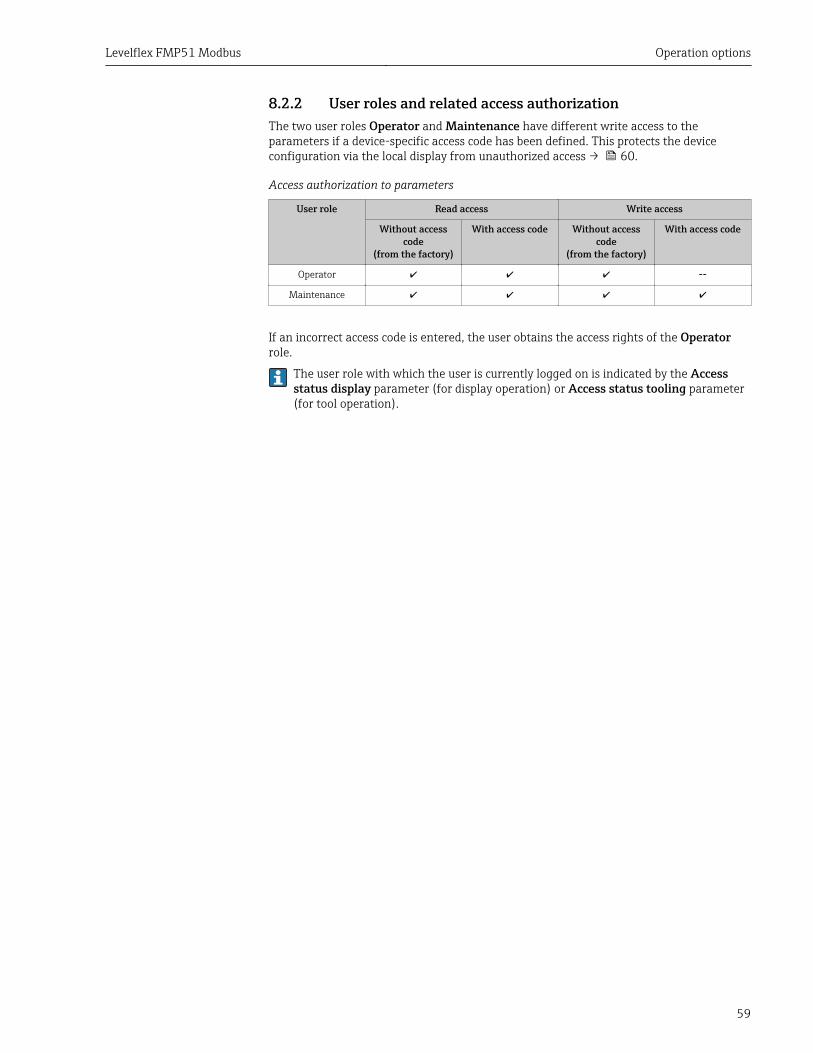
8.2.2 User roles and related access authorizationThe two user roles Operator and Maintenance have different write access to theparameters if a device-specific access code has been defined. This protects the deviceconfiguration via the local display from unauthorized access → 60.
Access authorization to parameters
User role Read access Write access
Without accesscode
(from the factory)
With access code Without accesscode
(from the factory)
With access code
Operator --
Maintenance
If an incorrect access code is entered, the user obtains the access rights of the Operatorrole.
The user role with which the user is currently logged on is indicated by the Accessstatus display parameter (for display operation) or Access status tooling parameter(for tool operation).
Operation options Levelflex FMP51 Modbus
60
8.2.3 Write protection via access codeUsing the device-specific access code, the parameters for the measuring deviceconfiguration are write-protected and their values can no longer be changed via localoperation.
Define access code via local display1. Navigate to: Setup → Advanced setup → Administration → Define access code
→ Define access code
2. Define a max. 4-digit numeric code as an access code.
3. Repeat the same code in Confirm access code parameter.The -symbol appears in front of all write-protected parameters.
Define access code via operating tool (e.g. FieldCare)1. Navigate to: Setup → Advanced setup → Administration → Define access code
2. Define a max. 4-digit numeric code as an access code.Write protection is active.
Parameters that can always be changedThe write protection does not include certain parameters that do not affect themeasurement. Despite the defined access code, they can always be modified, even if theother parameters are locked.
The device automatically locks the write-protected parameters again if a key is not pressedfor 10 minutes in the navigation and editing view. The device locks the write-protectedparameters automatically after 60 s if the user skips back to the measured value displaymode from the navigation and editing view.
• If write access is activated via access code, it can be also be deactivated only via theaccess code → 60.
• In the "Description of Device Parameters" documents, each write-protectedparameter is identified with the -symbol.
Levelflex FMP51 Modbus Operation options
61
8.2.4 Disabling write protection via access codeIf the -symbol appears on the local display in front of a parameter, the parameter iswrite-protected by a device-specific access code and its value cannot be changed at themoment using the local display → 60.
The locking of the write access via local operation can be disabled by entering the device-specific access code.
1. After you press , the input prompt for the access code appears.
2. Enter the access code.The -symbol in front of the parameters disappears; all previously write-protected parameters are now re-enabled.
8.2.5 Deactivation of the write protection via access code
Via local display1. Navigate to: Setup → Advanced setup → Administration → Define access code
→ Define access code
2. 0000.
3. Repeat 0000 in Confirm access code parameter.The write protection is deactivated. Parameters can be changed without enteringan access code.
Via an operating tool (e.g. FieldCare)1. Navigate to: Setup → Advanced setup → Administration → Define access code
2. 0000.The write protection is deactivated. Parameters can be changed without enteringan access code.
8.2.6 Write protection via write protection switchUnlike parameter write protection via a user-specific access code, this allows write accessto the entire operating menu - except for the "Contrast display" parameter - to be locked.
The parameter values are now read only and cannot be edited any more (exception"Contrast display" parameter):• Via local display• Via MODBUS RS485 protocol
1. Loosen the securing clamp.
2. Unscrew the electronics compartment cover.
Operation options Levelflex FMP51 Modbus
62
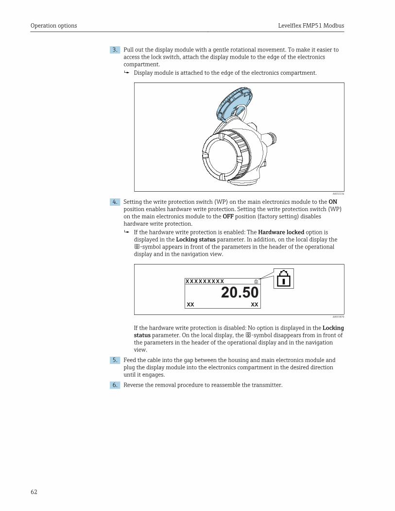
3. Pull out the display module with a gentle rotational movement. To make it easier toaccess the lock switch, attach the display module to the edge of the electronicscompartment.
Display module is attached to the edge of the electronics compartment.
A0032236
4. Setting the write protection switch (WP) on the main electronics module to the ONposition enables hardware write protection. Setting the write protection switch (WP)on the main electronics module to the OFF position (factory setting) disableshardware write protection.
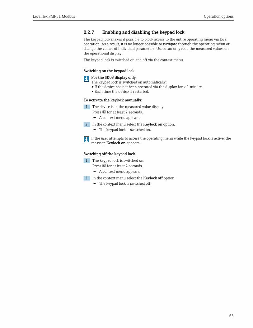
If the hardware write protection is enabled: The Hardware locked option isdisplayed in the Locking status parameter. In addition, on the local display the
-symbol appears in front of the parameters in the header of the operationaldisplay and in the navigation view.
X X X X X X XX X
20.50XXXX
A0015870
If the hardware write protection is disabled: No option is displayed in the Lockingstatus parameter. On the local display, the -symbol disappears from in front ofthe parameters in the header of the operational display and in the navigationview.
5. Feed the cable into the gap between the housing and main electronics module andplug the display module into the electronics compartment in the desired directionuntil it engages.
6. Reverse the removal procedure to reassemble the transmitter.
Levelflex FMP51 Modbus Operation options
63
8.2.7 Enabling and disabling the keypad lockThe keypad lock makes it possible to block access to the entire operating menu via localoperation. As a result, it is no longer possible to navigate through the operating menu orchange the values of individual parameters. Users can only read the measured values onthe operational display.
The keypad lock is switched on and off via the context menu.
Switching on the keypad lockFor the SD03 display onlyThe keypad lock is switched on automatically:• If the device has not been operated via the display for > 1 minute.• Each time the device is restarted.
To activate the keylock manually:1. The device is in the measured value display.
Press for at least 2 seconds.A context menu appears.
2. In the context menu select the Keylock on option.The keypad lock is switched on.
If the user attempts to access the operating menu while the keypad lock is active, themessage Keylock on appears.
Switching off the keypad lock1. The keypad lock is switched on.
Press for at least 2 seconds.A context menu appears.
2. In the context menu select the Keylock off option.The keypad lock is switched off.
Operation options Levelflex FMP51 Modbus
64
8.3 Display and operating module
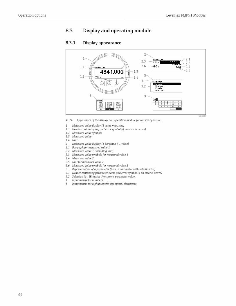
8.3.1 Display appearance
3.1
3.2
2.1
2.2
2.4
2.5
1.1
1.2
1.3
1.4
2.3
2.6
1
2
3
45
ESC
OP
EN
OP
EN
E
ABC_ DEFG
UserHIJK
LMNO PQRS TUVW
XYZ Aa1
3 40 1 295 6 87
20
A0012635
14 Appearance of the display and operation module for on-site operation
1 Measured value display (1 value max. size)1.1 Header containing tag and error symbol (if an error is active)1.2 Measured value symbols1.3 Measured value1.4 Unit2 Measured value display (1 bargraph + 1 value)2.1 Bargraph for measured value 12.2 Measured value 1 (including unit)2.3 Measured value symbols for measured value 12.4 Measured value 22.5 Unit for measured value 22.6 Measured value symbols for measured value 23 Representation of a parameter (here: a parameter with selection list)3.1 Header containing parameter name and error symbol (if an error is active)3.2 Selection list; marks the current parameter value.4 Input matrix for numbers5 Input matrix for alphanumeric and special characters
Levelflex FMP51 Modbus Operation options
65
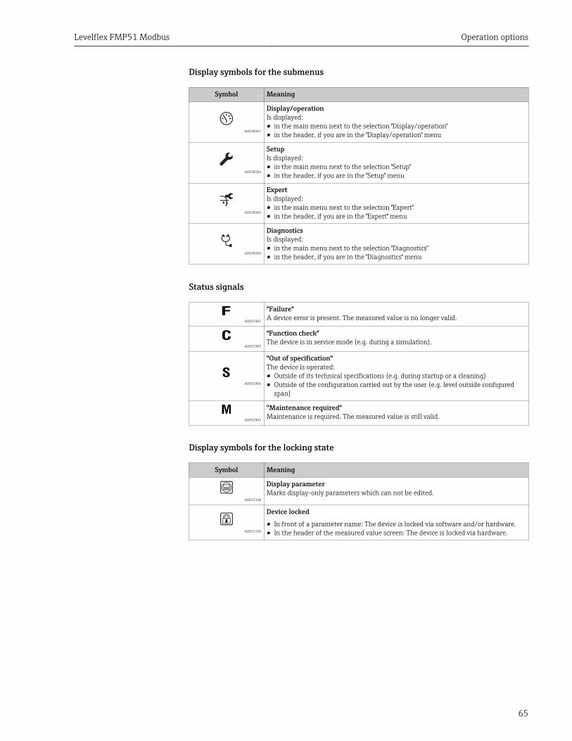
Display symbols for the submenus
Symbol Meaning
A0018367
Display/operationIs displayed:• in the main menu next to the selection "Display/operation"• in the header, if you are in the "Display/operation" menu
A0018364
SetupIs displayed:• in the main menu next to the selection "Setup"• in the header, if you are in the "Setup" menu
A0018365
ExpertIs displayed:• in the main menu next to the selection "Expert"• in the header, if you are in the "Expert" menu
A0018366
DiagnosticsIs displayed:• in the main menu next to the selection "Diagnostics"• in the header, if you are in the "Diagnostics" menu
Status signals
A0032902
"Failure"A device error is present. The measured value is no longer valid.
A0032903
"Function check"The device is in service mode (e.g. during a simulation).
S A0032904
"Out of specification"The device is operated:• Outside of its technical specifications (e.g. during startup or a cleaning)• Outside of the configuration carried out by the user (e.g. level outside configured
span)
A0032905
"Maintenance required"Maintenance is required. The measured value is still valid.
Display symbols for the locking state
Symbol Meaning
A0013148
Display parameterMarks display-only parameters which can not be edited.
A0013150
Device locked
• In front of a parameter name: The device is locked via software and/or hardware.• In the header of the measured value screen: The device is locked via hardware.
Operation options Levelflex FMP51 Modbus
66
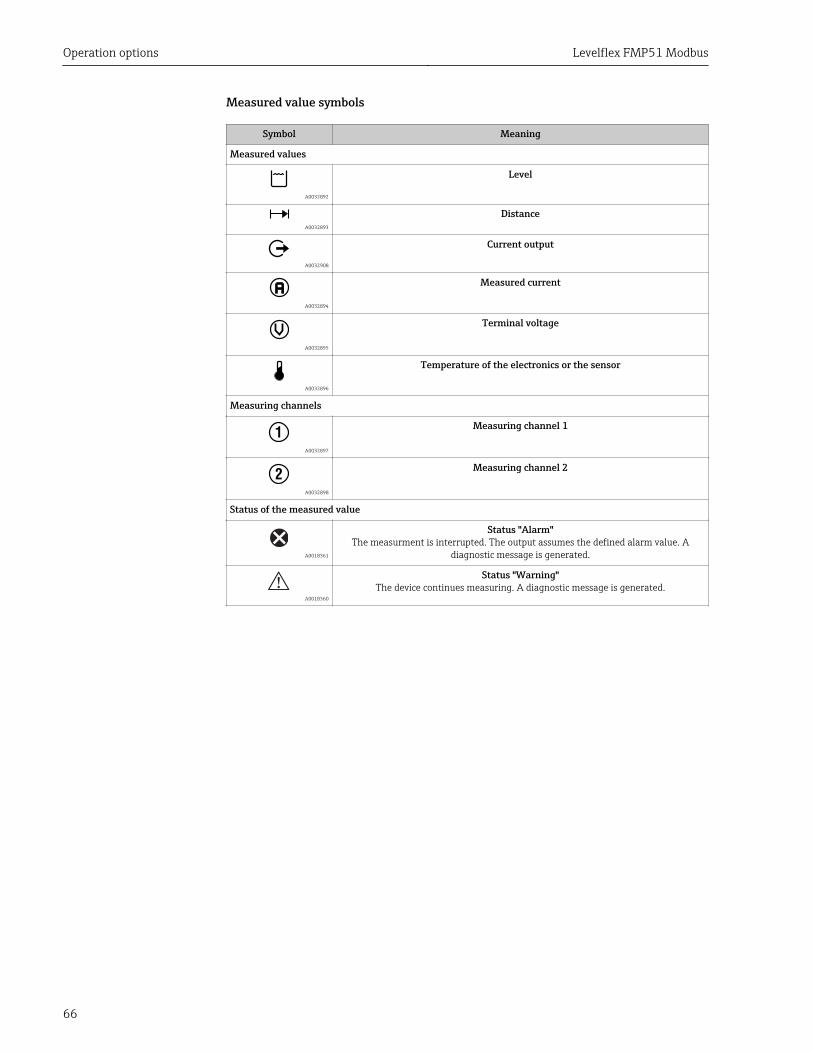
Measured value symbols
Symbol Meaning
Measured values
A0032892
Level
A0032893
Distance
A0032908
Current output
A0032894
Measured current
A0032895
Terminal voltage
A0032896
Temperature of the electronics or the sensor
Measuring channels
1 A0032897
Measuring channel 1
2 A0032898
Measuring channel 2
Status of the measured value
A0018361
Status "Alarm"The measurment is interrupted. The output assumes the defined alarm value. A
diagnostic message is generated.
A0018360
Status "Warning"The device continues measuring. A diagnostic message is generated.
Levelflex FMP51 Modbus Operation options
67
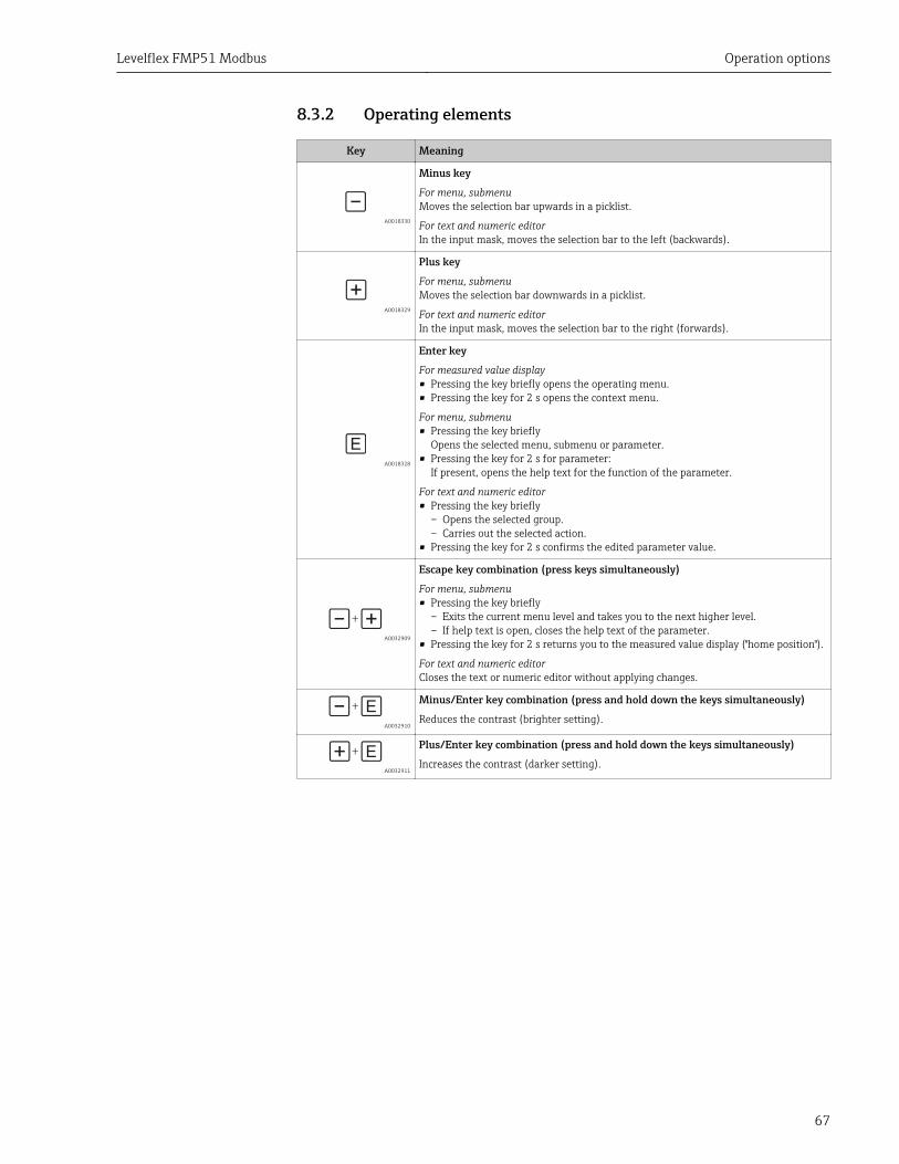
8.3.2 Operating elements
Key Meaning
A0018330
Minus key
For menu, submenuMoves the selection bar upwards in a picklist.
For text and numeric editorIn the input mask, moves the selection bar to the left (backwards).
A0018329
Plus key
For menu, submenuMoves the selection bar downwards in a picklist.
For text and numeric editorIn the input mask, moves the selection bar to the right (forwards).
A0018328
Enter key
For measured value display• Pressing the key briefly opens the operating menu.• Pressing the key for 2 s opens the context menu.
For menu, submenu• Pressing the key briefly
Opens the selected menu, submenu or parameter.• Pressing the key for 2 s for parameter:
If present, opens the help text for the function of the parameter.
For text and numeric editor• Pressing the key briefly
– Opens the selected group.– Carries out the selected action.
• Pressing the key for 2 s confirms the edited parameter value.
+
A0032909
Escape key combination (press keys simultaneously)
For menu, submenu• Pressing the key briefly
– Exits the current menu level and takes you to the next higher level.– If help text is open, closes the help text of the parameter.
• Pressing the key for 2 s returns you to the measured value display ("home position").
For text and numeric editorCloses the text or numeric editor without applying changes.
+
A0032910
Minus/Enter key combination (press and hold down the keys simultaneously)
Reduces the contrast (brighter setting).
+
A0032911
Plus/Enter key combination (press and hold down the keys simultaneously)
Increases the contrast (darker setting).
Operation options Levelflex FMP51 Modbus
68
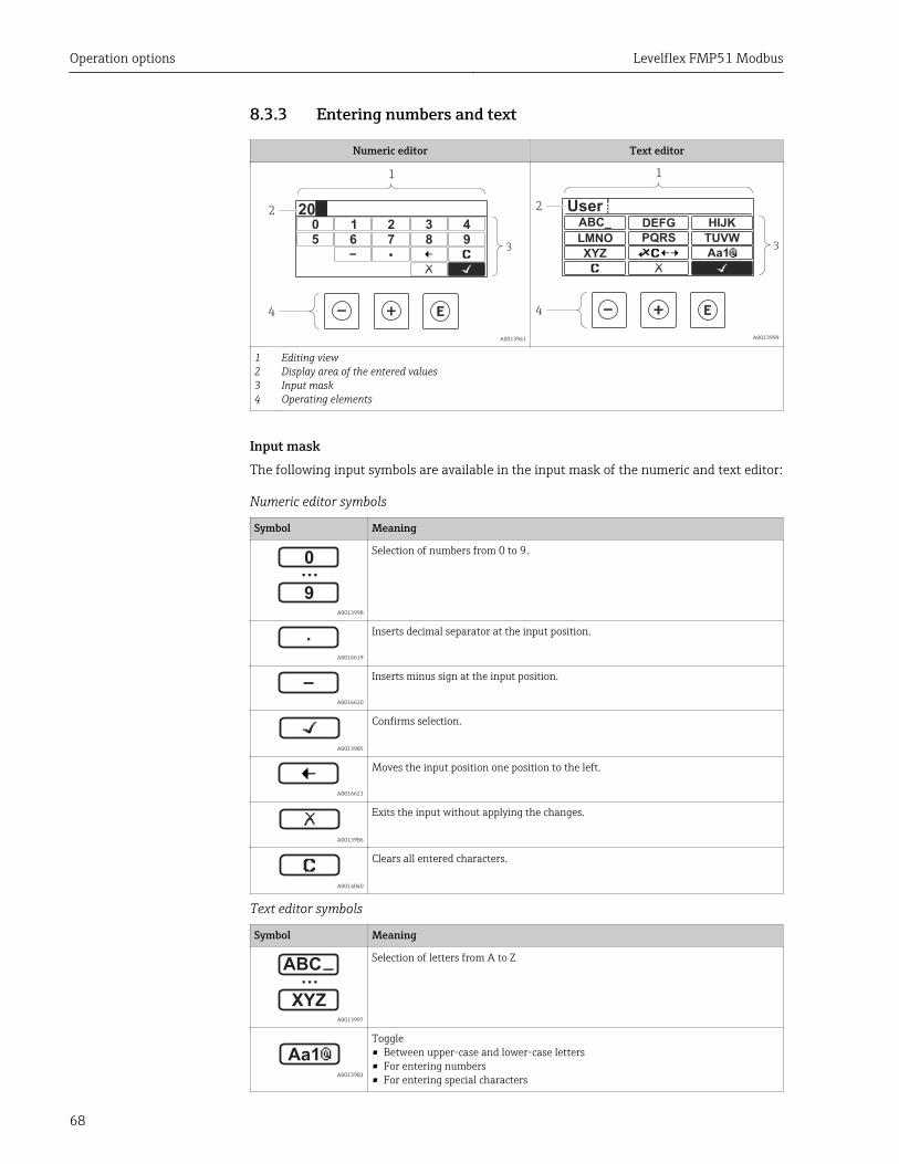
8.3.3 Entering numbers and text
Numeric editor Text editor
3
2
1
4
3 40 1 295 6 87
20
A0013941
ABC_ DEFG
UserHIJK
LMNO PQRS TUVW
XYZ Aa13
2
1
4
A0013999
1234
Editing viewDisplay area of the entered valuesInput maskOperating elements
Input maskThe following input symbols are available in the input mask of the numeric and text editor:
Numeric editor symbols
Symbol Meaning
…0
9 A0013998
Selection of numbers from 0 to 9.
.
A0016619
Inserts decimal separator at the input position.
– A0016620
Inserts minus sign at the input position.
A0013985
Confirms selection.
A0016621
Moves the input position one position to the left.
A0013986
Exits the input without applying the changes.
A0014040
Clears all entered characters.
Text editor symbols
Symbol Meaning
XYZ
ABC_…
A0013997
Selection of letters from A to Z
Aa1 A0013981
Toggle• Between upper-case and lower-case letters• For entering numbers• For entering special characters
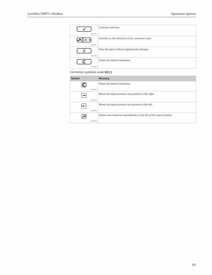
Levelflex FMP51 Modbus Operation options
69
A0013985
Confirms selection.
A0013987
Switches to the selection of the correction tools.
A0013986
Exits the input without applying the changes.
A0014040
Clears all entered characters.
Correction symbols under
Symbol Meaning
A0032907
Clears all entered characters.
A0018324
Moves the input position one position to the right.
A0018326
Moves the input position one position to the left.
A0032906
Deletes one character immediately to the left of the input position.
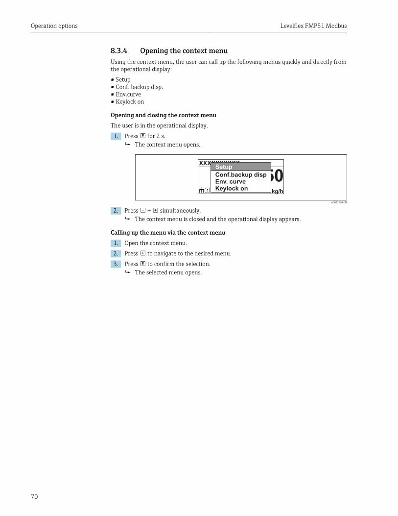
Operation options Levelflex FMP51 Modbus
70
8.3.4 Opening the context menuUsing the context menu, the user can call up the following menus quickly and directly fromthe operational display:
• Setup• Conf. backup disp.• Env.curve• Keylock on
Opening and closing the context menuThe user is in the operational display.
1. Press for 2 s.The context menu opens.
XXXXXXXXXX
kg/h
50Setup
Conf.backup dispEnv. curveKeylock on
A0033110-EN
2. Press + simultaneously.The context menu is closed and the operational display appears.
Calling up the menu via the context menu1. Open the context menu.
2. Press to navigate to the desired menu.
3. Press to confirm the selection.The selected menu opens.
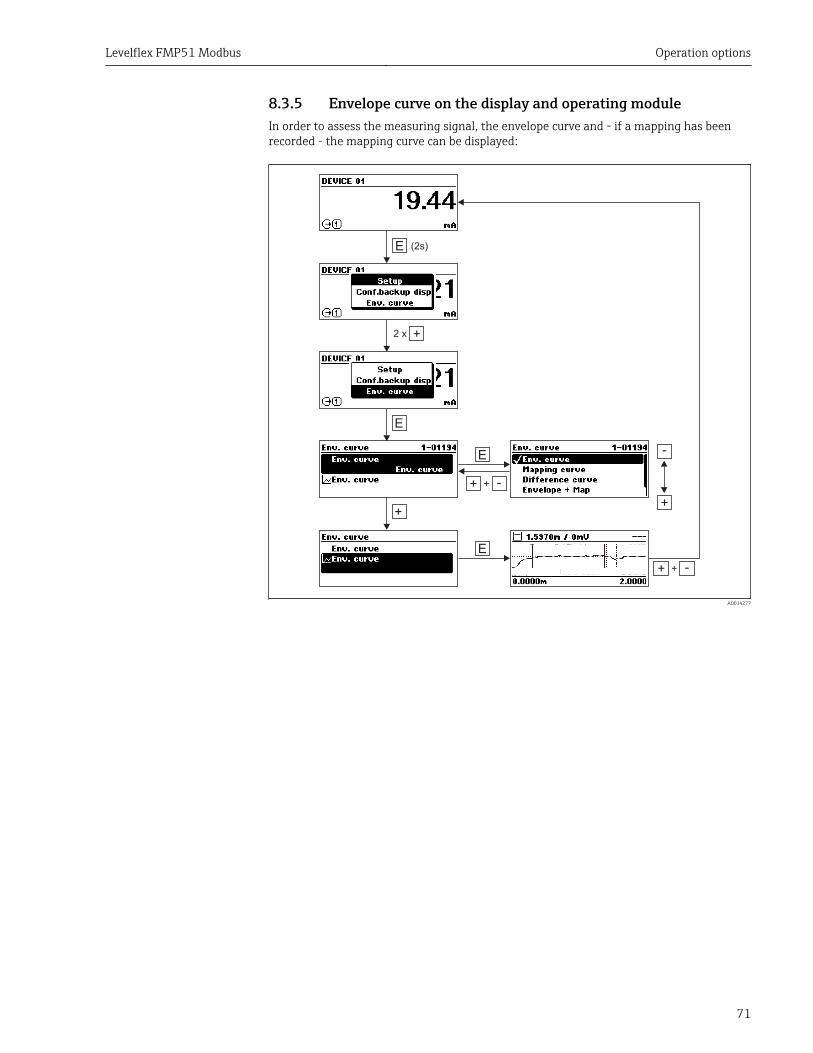
Levelflex FMP51 Modbus Operation options
71
8.3.5 Envelope curve on the display and operating moduleIn order to assess the measuring signal, the envelope curve and - if a mapping has beenrecorded - the mapping curve can be displayed:
E
+
(2s)
E
2�x
E
+ -+
+
-
+
E
+ -+
A0014277
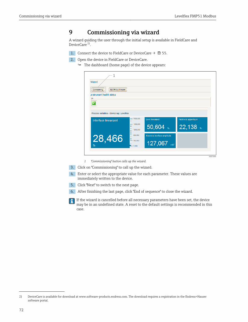
Commissioning via wizard Levelflex FMP51 Modbus
72
9 Commissioning via wizardA wizard guiding the user through the initial setup is available in FieldCare andDeviceCare 2).
1. Connect the device to FieldCare or DeviceCare → 55.
2. Open the device in FieldCare or DeviceCare.The dashboard (home page) of the device appears:
1
A0025866
1 "Commissioning" button calls up the wizard.
3. Click on "Commissioning" to call up the wizard.
4. Enter or select the appropriate value for each parameter. These values areimmediately written to the device.
5. Click "Next" to switch to the next page.
6. After finishing the last page, click "End of sequence" to close the wizard.
If the wizard is cancelled before all necessary parameters have been set, the devicemay be in an undefined state. A reset to the default settings is recommended in thiscase.
2) DeviceCare is available for download at www.software-products.endress.com. The download requires a registration in the Endress+Hausersoftware portal.
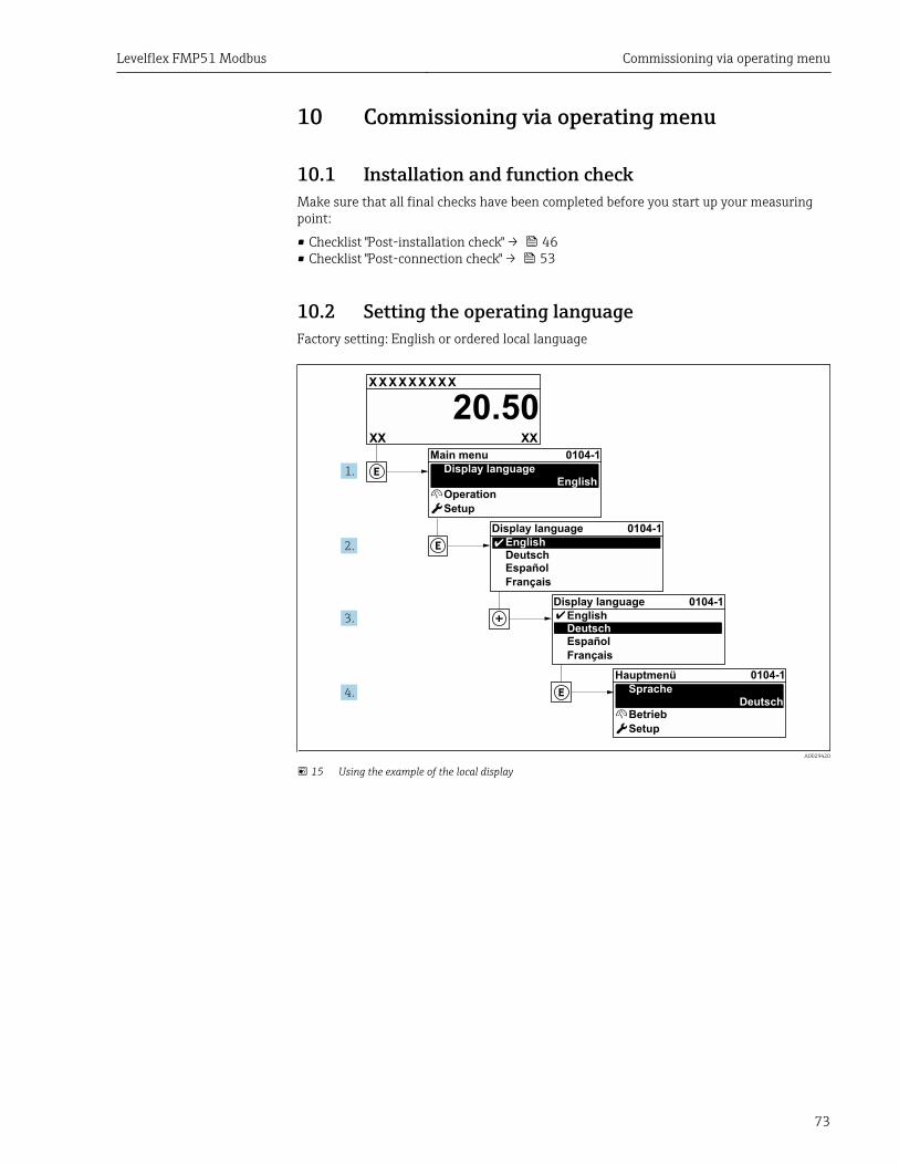
Levelflex FMP51 Modbus Commissioning via operating menu
73
10 Commissioning via operating menu
10.1 Installation and function checkMake sure that all final checks have been completed before you start up your measuringpoint:
• Checklist "Post-installation check" → 46• Checklist "Post-connection check" → 53
10.2 Setting the operating languageFactory setting: English or ordered local language
X X X X X X XX X
20.50
Operation
Setup
Main menu 0104-1Display language
English
Español
Français
Display languageEnglishDeutsch
Ã
0104-1
Ã
Español
Français
Display languageEnglishDeutsch
0104-1
Betrieb
Setup
HauptmenüSprache
Deutsch
0104-1
XXXX
1.
2.
3.
4.
A0029420
15 Using the example of the local display
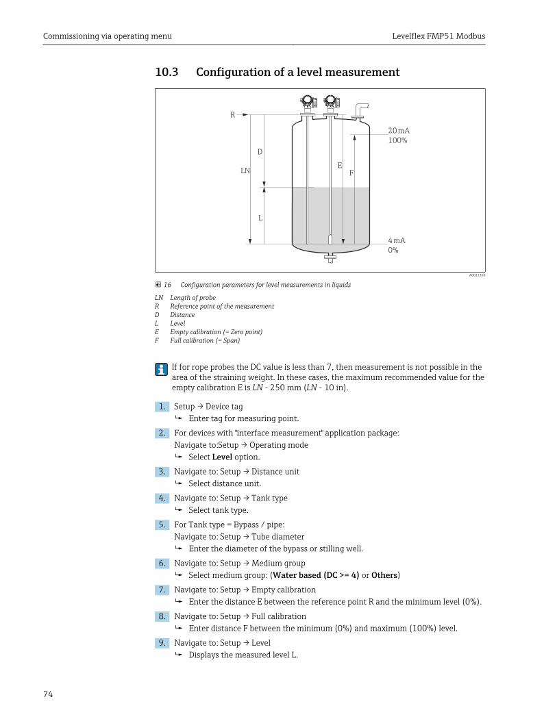
Commissioning via operating menu Levelflex FMP51 Modbus
74
10.3 Configuration of a level measurement
F
L
D
E
20 mA
100%
4 mA
0%
LN
R
A0011360
16 Configuration parameters for level measurements in liquids
LN Length of probeR Reference point of the measurementD DistanceL LevelE Empty calibration (= Zero point)F Full calibration (= Span)
If for rope probes the DC value is less than 7, then measurement is not possible in thearea of the straining weight. In these cases, the maximum recommended value for theempty calibration E is LN - 250 mm (LN - 10 in).
1. Setup → Device tagEnter tag for measuring point.
2. For devices with "interface measurement" application package:Navigate to:Setup → Operating mode
Select Level option.
3. Navigate to: Setup → Distance unitSelect distance unit.
4. Navigate to: Setup → Tank typeSelect tank type.
5. For Tank type = Bypass / pipe:Navigate to: Setup → Tube diameter
Enter the diameter of the bypass or stilling well.
6. Navigate to: Setup → Medium groupSelect medium group: (Water based (DC >= 4) or Others)
7. Navigate to: Setup → Empty calibrationEnter the distance E between the reference point R and the minimum level (0%).
8. Navigate to: Setup → Full calibrationEnter distance F between the minimum (0%) and maximum (100%) level.
9. Navigate to: Setup → LevelDisplays the measured level L.
Levelflex FMP51 Modbus Commissioning via operating menu
75
10. Navigate to: Setup → DistanceDisplays the distance D between the reference point R and the level L.
11. Navigate to: Setup → Signal qualityDisplays the signal quality of the level echo.
12. For operation via local display:Navigate to: Setup → Mapping → Confirm distance
Compare the displayed distance to the real distance in order to start therecording of the mapping curve if required 3).
13. For operation via operating tool:Navigate to: Setup → Confirm distance
Compare the displayed distance to the real distance in order to start therecording of the mapping curve if required 3).
3) For FMP54 with gas phase compensation (product structure: feature 540 "Application Package", option EF or EG) a map must NOT be recorded.
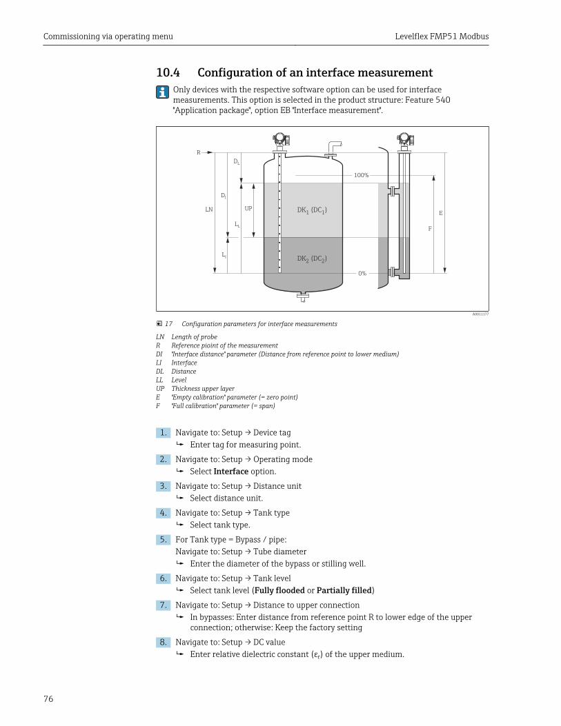
Commissioning via operating menu Levelflex FMP51 Modbus
76
10.4 Configuration of an interface measurementOnly devices with the respective software option can be used for interfacemeasurements. This option is selected in the product structure: Feature 540"Application package", option EB "Interface measurement".
DL
LL
F
LI
UP
DI
LNE
R
0%
100%
DK (DC )2 2
DK DC1 1
( )
A0011177
17 Configuration parameters for interface measurements
LN Length of probeR Reference pioint of the measurementDI "Interface distance" parameter (Distance from reference point to lower medium)LI InterfaceDL DistanceLL LevelUP Thickness upper layerE "Empty calibration" parameter (= zero point)F "Full calibration" parameter (= span)
1. Navigate to: Setup → Device tagEnter tag for measuring point.
2. Navigate to: Setup → Operating modeSelect Interface option.
3. Navigate to: Setup → Distance unitSelect distance unit.
4. Navigate to: Setup → Tank typeSelect tank type.
5. For Tank type = Bypass / pipe:Navigate to: Setup → Tube diameter
Enter the diameter of the bypass or stilling well.
6. Navigate to: Setup → Tank levelSelect tank level (Fully flooded or Partially filled)
7. Navigate to: Setup → Distance to upper connectionIn bypasses: Enter distance from reference point R to lower edge of the upperconnection; otherwise: Keep the factory setting
8. Navigate to: Setup → DC valueEnter relative dielectric constant (εr) of the upper medium.
Levelflex FMP51 Modbus Commissioning via operating menu
77
9. Navigate to: Setup → Empty calibrationEnter the distance E between the reference point R and the minimum level (0%).
10. Navigate to: Setup → Full calibrationEnter distance F between the minimum (0%) and maximum (100%) level.
11. Navigate to: Setup → LevelDisplays the measured level LL.
12. Navigate to: Setup → InterfaceDisplays the interface height LI.
13. Navigate to: Setup → DistanceDisplays the distance DL between the reference point R and the level LL.
14. Navigate to: Setup → Interface distanceDisplays the distance DI between the reference point R and the interface LI.
15. Navigate to: Setup → Signal qualityDisplays the signal quality of the level echo.
16. For operation via local display:Navigate to: Setup → Mapping → Confirm distance
Compare the displayed distance to the real distance in order to start therecording of the mapping curve if required 4).
17. For operation via operating tool (e.g. FieldCare):Navigate to: Setup → Confirm distance
Angezeigte Distanz mit tatsächlichem Wert vergleichen, um gegebenenfalls dieAufnahme einer Störechoausblendungskurve zu starten 4).
4) For FMP54 with gas phase compensation (product structure: feature 540 "Application Package", option EF or EG) a map must NOT be recorded.
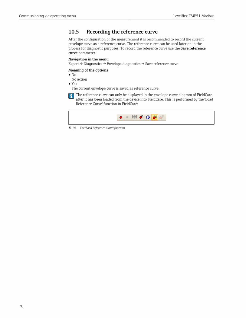
Commissioning via operating menu Levelflex FMP51 Modbus
78
10.5 Recording the reference curveAfter the configuration of the measurement it is recommended to record the currentenvelope curve as a reference curve. The reference curve can be used later on in theprocess for diagnostic purposes. To record the reference curve use the Save referencecurve parameter.
Navigation in the menuExpert → Diagnostics → Envelope diagnostics → Save reference curve
Meaning of the options• No
No action• Yes
The current envelope curve is saved as reference curve.
The reference curve can only be displayed in the envelope curve diagram of FieldCareafter it has been loaded from the device into FieldCare. This is performed by the "LoadReference Curve" function in FieldCare:
18 The "Load Reference Curve" function
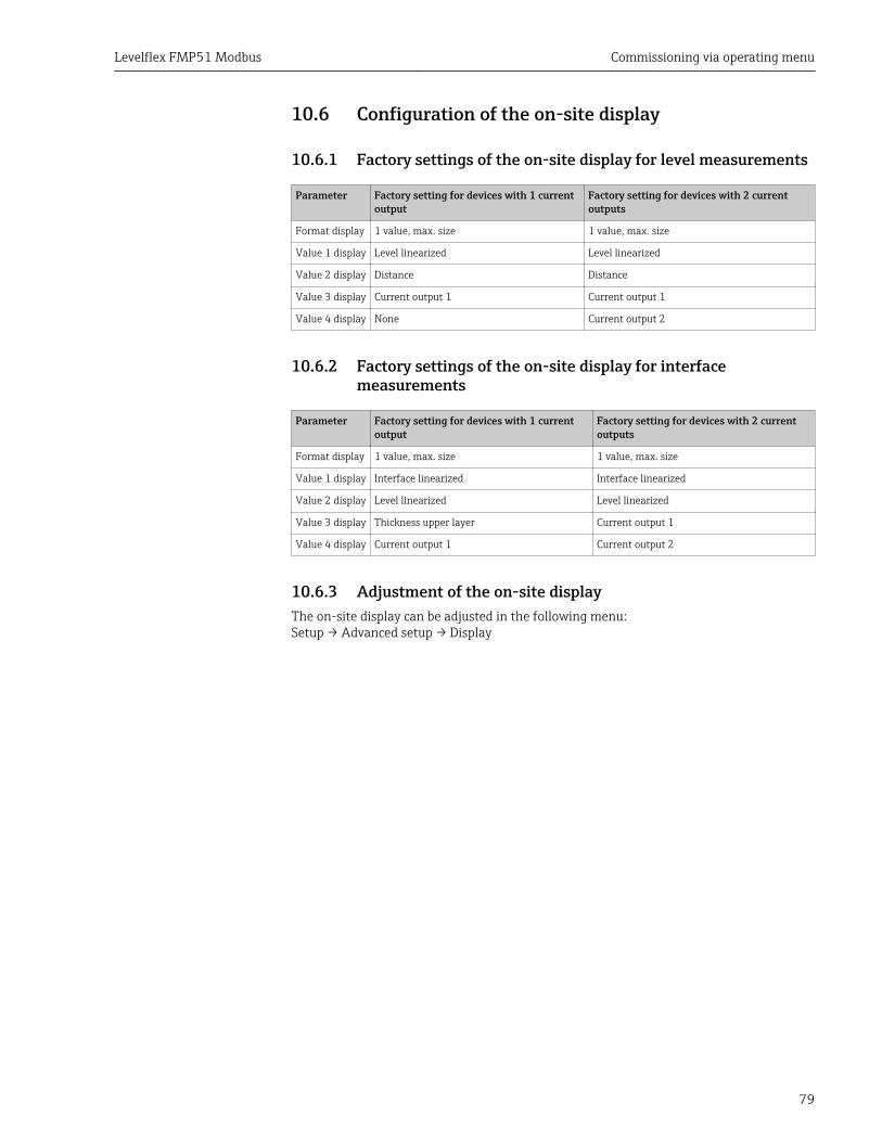
Levelflex FMP51 Modbus Commissioning via operating menu
79
10.6 Configuration of the on-site display
10.6.1 Factory settings of the on-site display for level measurements
Parameter Factory setting for devices with 1 currentoutput
Factory setting for devices with 2 currentoutputs
Format display 1 value, max. size 1 value, max. size
Value 1 display Level linearized Level linearized
Value 2 display Distance Distance
Value 3 display Current output 1 Current output 1
Value 4 display None Current output 2
10.6.2 Factory settings of the on-site display for interfacemeasurements
Parameter Factory setting for devices with 1 currentoutput
Factory setting for devices with 2 currentoutputs
Format display 1 value, max. size 1 value, max. size
Value 1 display Interface linearized Interface linearized
Value 2 display Level linearized Level linearized
Value 3 display Thickness upper layer Current output 1
Value 4 display Current output 1 Current output 2
10.6.3 Adjustment of the on-site displayThe on-site display can be adjusted in the following menu:Setup → Advanced setup → Display
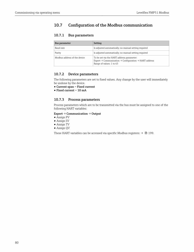
Commissioning via operating menu Levelflex FMP51 Modbus
80
10.7 Configuration of the Modbus communication
10.7.1 Bus parameters
Bus parameter Setting
Baud rate Is adjusted automatically; no manual setting required
Parity Is adjusted automatically; no manual setting required
Modbus address of the device To be set via the HART address parameter:Expert → Communication → Configuration → HART addressRange of values: 1 to 63
10.7.2 Device parametersThe following parameters are set to fixed values. Any change by the user will immediatelybe undone by the device.• Current span = Fixed current• Fixed current = 10 mA
10.7.3 Process parametersProcess parameters which are to be transmitted via the bus must be assigned to one of thefollowing HART variables:
Expert → Communication → Output• Assign PV• Assign SV• Assign TV• Assign QV
These HART variables can be accessed via specific Modbus registers: → 199.
Levelflex FMP51 Modbus Commissioning via operating menu
81
10.8 Configuration managementAfter commissioning, you can save the current device configuration, copy it to anothermeasuring point or restore the previous device configuration. You can do so using theConfiguration management parameter and its options.
Navigation path in the operating menuSetup → Advanced setup → Configuration backup display → Configuration management
Meaning of the options• Cancel
No action is executed and the user exits the parameter.• Execute backup
A backup copy of the current device configuration in the HistoROM (built-in in thedevice) is saved to the display module of the device. The backup copy comprises thetransmitter and sensor data of the device.
• RestoreThe last backup copy of the device configuration is copied from the display module to theHistoROM of the device. The backup copy comprises the transmitter and sensor data ofthe device.
• DuplicateThe transmitter configuration is duplicated to another device using the transmitterdisplay module. The following parameters, which characterize the individual measuringpoint are not included in the transmitted configuration:– HART date code– HART short tag– HART message– HART descriptor– HART address– Device tag– Medium type
• CompareThe device configuration saved in the display module is compared to the current deviceconfiguration of the HistoROM. The result of this comparison is displayed in theComparison result parameter.
• Clear backup dataThe backup copy of the device configuration is deleted from the display module of thedevice.
While this action is in progress, the configuration cannot be edited via the localdisplay and a message on the processing status appears on the display.
If an existing backup is restored to a different device using the Restore option, it mayoccur that some device functionalities are no longer available. In some cases even adevice reset → 177 will not restore the original status..
In order to transmit a configuration to a different device, the Duplicate option shouldalways be used.

Commissioning via operating menu Levelflex FMP51 Modbus
82
10.9 Protection of the settings against unauthorizedchanges
There are two ways to protect the settings against unauthorized changes:
• Via parameter settings (software locking) → 60• Via locking switch (hardware locking) → 61
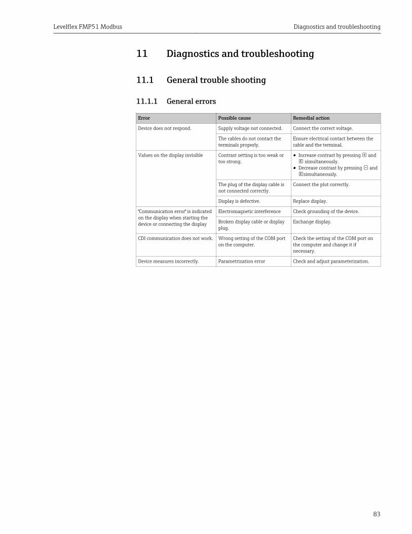
Levelflex FMP51 Modbus Diagnostics and troubleshooting
83
11 Diagnostics and troubleshooting
11.1 General trouble shooting
11.1.1 General errors
Error Possible cause Remedial action
Device does not respond. Supply voltage not connected. Connect the correct voltage.
The cables do not contact theterminals properly.
Ensure electrical contact between thecable and the terminal.
Values on the display invisible Contrast setting is too weak ortoo strong.
• Increase contrast by pressing and simultaneously.
• Decrease contrast by pressing andsimultaneously.
The plug of the display cable isnot connected correctly.
Connect the plut correctly.
Display is defective. Replace display.
"Communication error" is indicatedon the display when starting thedevice or connecting the display
Electromagnetic interference Check grounding of the device.
Broken display cable or displayplug.
Exchange display.
CDI communication does not work. Wrong setting of the COM porton the computer.
Check the setting of the COM port onthe computer and change it ifnecessary.
Device measures incorrectly. Parametrization error Check and adjust parameterization.
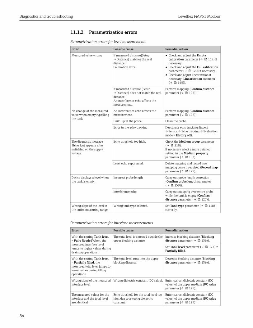
Diagnostics and troubleshooting Levelflex FMP51 Modbus
84
11.1.2 Parametrization errors
Parametrization errors for level measurements
Error Possible cause Remedial action
Measured value wrong If measured distance(Setup→ Distance) matches the realdistance:Calibration error
• Check and adjust the Emptycalibration parameter (→ 119) ifnecessary.
• Check and adjust the Full calibrationparameter (→ 120) if necessary.
• Check and adjust linearization ifnecessary (Linearization submenu(→ 145)).
If measured distance (Setup→ Distance) does not match the realdistance:An interference echo affects themeasurement.
Perform mapping (Confirm distanceparameter (→ 127)).
No change of the measuredvalue when emptying/fillingthe tank
An interference echo affects themeasurement.
Perform mapping (Confirm distanceparameter (→ 127)).
Build-up at the probe. Clean the probe.
Error in the echo tracking Deactivate echo tracking: Expert→ Sensor → Echo tracking → Evaluationmode = History off).
The diagnostic message Echo lost appears afterswitching on the supplyvoltage.
Echo threshold too high. Check the Medium group parameter(→ 118).If necessary select a more detailedsetting in the Medium propertyparameter (→ 133).
Level echo suppressed. Delete mapping and record newmapping curve if required (Record mapparameter (→ 129)).
Device displays a level whenthe tank is empty.
Incorrect probe length Carry out probe length correction(Confirm probe length parameter(→ 159)).
Interference echo Carry out mapping over entire probewhile the tank is empty (Confirmdistance parameter (→ 127)).
Wrong slope of the level inthe entire measuring range
Wrong tank type selected. Set Tank type parameter (→ 118)correctly.
Parametrization errors for interface measurements
Error Possible cause Remedial action
With the setting Tank level= Fully floodedWhen, themeasured interface leveljumps to higher values duringdraining operations.
The total level is detected outside theupper blocking distance.
Increase blocking distance (Blockingdistance parameter (→ 136)).
Set Tank level parameter (→ 124) =Partially filled.
With the setting Tank level= Partially filled, themeasured total level jumps tolower values during fillingoperations.
The total level runs into the upperblocking distance.
Decrease blocking distance (Blockingdistance parameter (→ 136)).
Wrong slope of the measuredinterface level
Wrong dielectric constant (DC value). Enter correct dielectric constant (DCvalue) of the upper medium (DC valueparameter (→ 125)).
The measured values for theinterface and the total levelare identical
Echo threshold for the total level toohigh due to a wrong dielectricconstant.
Enter correct dielectric constant (DCvalue) of the upper medium (DC valueparameter (→ 125)).

Levelflex FMP51 Modbus Diagnostics and troubleshooting
85
Error Possible cause Remedial action
If the interface layers arethin, the total level jumps tothe interface level.
The thickness of the upper mediumis less than 60 mm (2.4 in).
Interface measurement is only possibleif the thickness of the interface isgreater than 60 mm (2.4 in).
The measured interface layerjumps.
Emulsion layer present. Emulsion layers affect themeasurement.
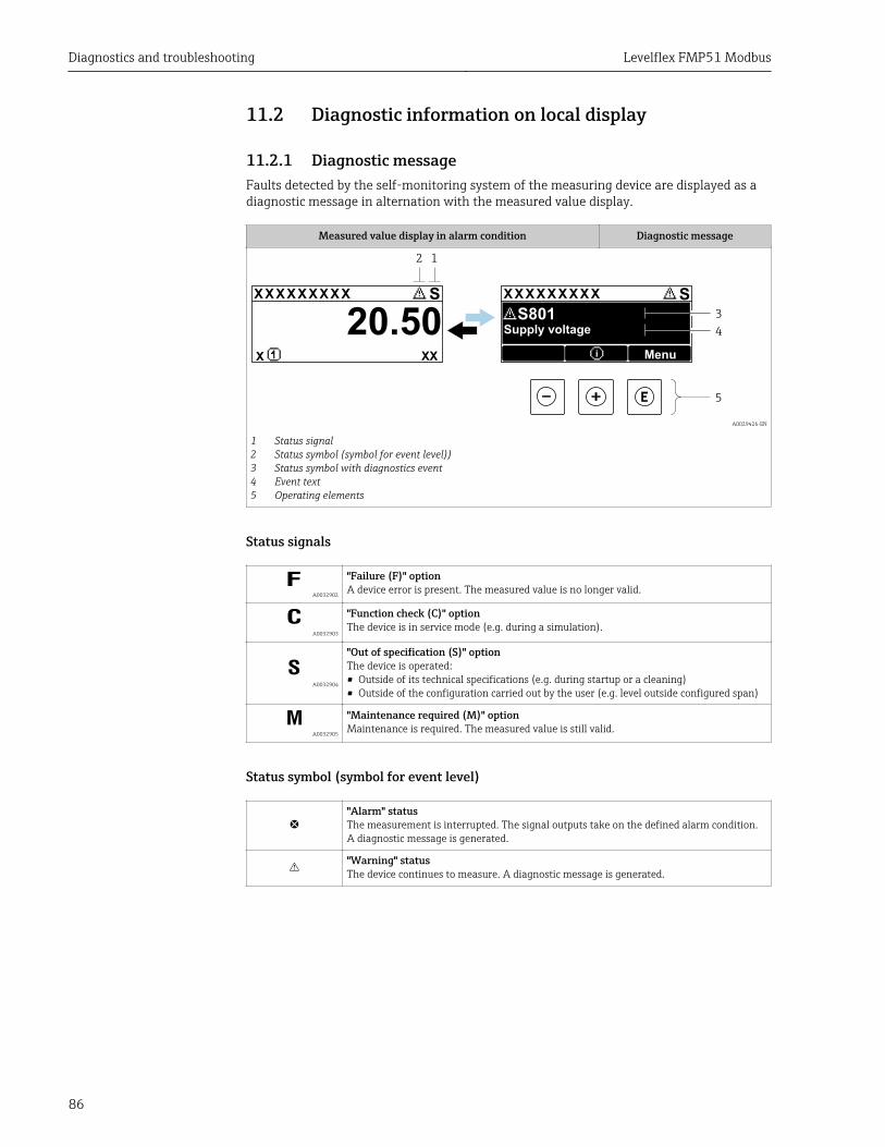
Diagnostics and troubleshooting Levelflex FMP51 Modbus
86
11.2 Diagnostic information on local display
11.2.1 Diagnostic messageFaults detected by the self-monitoring system of the measuring device are displayed as adiagnostic message in alternation with the measured value display.
Measured value display in alarm condition Diagnostic message
1
4
3
X X X X X X XX X X X X X X X XX X
2
S S
XX
20.50
5
X i
S801
Menu
Supply voltage
A0029426-EN
1 Status signal2 Status symbol (symbol for event level))3 Status symbol with diagnostics event4 Event text5 Operating elements
Status signals
A0032902
"Failure (F)" optionA device error is present. The measured value is no longer valid.
A0032903
"Function check (C)" optionThe device is in service mode (e.g. during a simulation).
S A0032904
"Out of specification (S)" optionThe device is operated:• Outside of its technical specifications (e.g. during startup or a cleaning)• Outside of the configuration carried out by the user (e.g. level outside configured span)
A0032905
"Maintenance required (M)" optionMaintenance is required. The measured value is still valid.
Status symbol (symbol for event level)
"Alarm" statusThe measurement is interrupted. The signal outputs take on the defined alarm condition.A diagnostic message is generated.
"Warning" statusThe device continues to measure. A diagnostic message is generated.
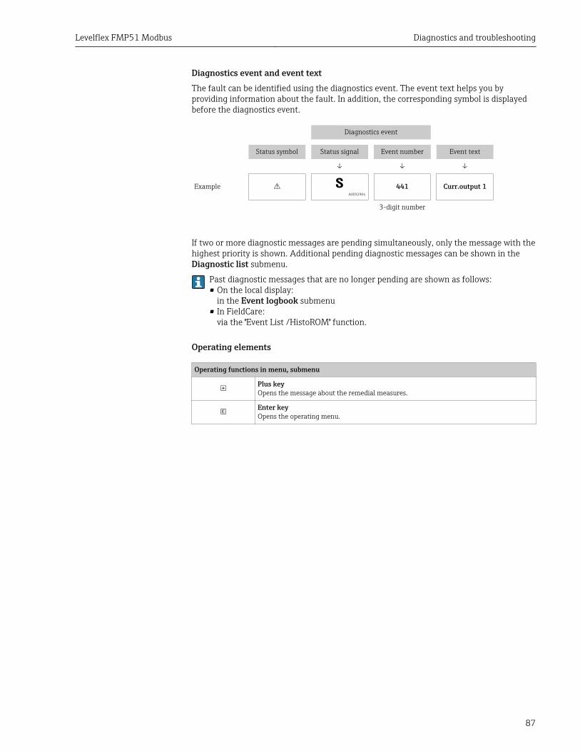
Levelflex FMP51 Modbus Diagnostics and troubleshooting
87
Diagnostics event and event textThe fault can be identified using the diagnostics event. The event text helps you byproviding information about the fault. In addition, the corresponding symbol is displayedbefore the diagnostics event.
Diagnostics event
Status symbol Status signal Event number Event text
↓ ↓ ↓
Example S A0032904
441 Curr.output 1
3-digit number
If two or more diagnostic messages are pending simultaneously, only the message with thehighest priority is shown. Additional pending diagnostic messages can be shown in theDiagnostic list submenu.
Past diagnostic messages that are no longer pending are shown as follows:• On the local display:
in the Event logbook submenu• In FieldCare:
via the "Event List /HistoROM" function.
Operating elements
Operating functions in menu, submenu
Plus keyOpens the message about the remedial measures.
Enter keyOpens the operating menu.
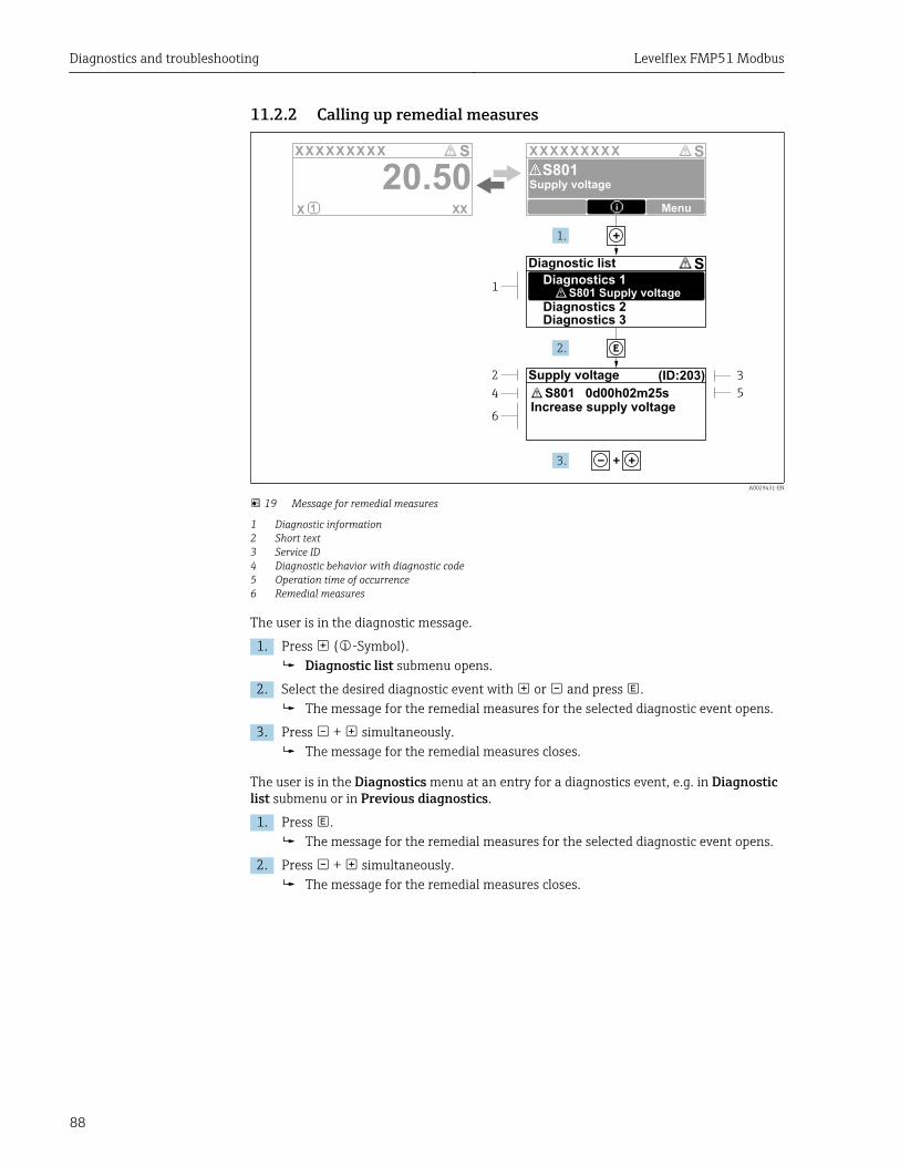
Diagnostics and troubleshooting Levelflex FMP51 Modbus
88
11.2.2 Calling up remedial measures
X X X X X X XX X X X X X X X XX XS S
XX
20.50X i
S801
Menu
S
(ID:203)
S801 0d00h02m25s
1
2
4
6
3
5
1.
2.
3.
Increase supply voltage
S801 Supply voltage
Diagnostic list
Diagnostics 1
Diagnostics 2Diagnostics 3
Supply voltage
Supply voltage
A0029431-EN
19 Message for remedial measures
1 Diagnostic information2 Short text3 Service ID4 Diagnostic behavior with diagnostic code5 Operation time of occurrence6 Remedial measures
The user is in the diagnostic message.
1. Press ( -Symbol).Diagnostic list submenu opens.
2. Select the desired diagnostic event with or and press .The message for the remedial measures for the selected diagnostic event opens.
3. Press + simultaneously.The message for the remedial measures closes.
The user is in the Diagnostics menu at an entry for a diagnostics event, e.g. in Diagnosticlist submenu or in Previous diagnostics.
1. Press .The message for the remedial measures for the selected diagnostic event opens.
2. Press + simultaneously.The message for the remedial measures closes.
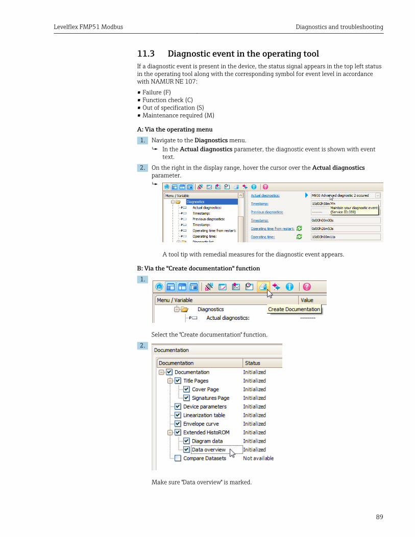
Levelflex FMP51 Modbus Diagnostics and troubleshooting
89
11.3 Diagnostic event in the operating toolIf a diagnostic event is present in the device, the status signal appears in the top left statusin the operating tool along with the corresponding symbol for event level in accordancewith NAMUR NE 107:
• Failure (F)• Function check (C)• Out of specification (S)• Maintenance required (M)
A: Via the operating menu1. Navigate to the Diagnostics menu.
In the Actual diagnostics parameter, the diagnostic event is shown with eventtext.
2. On the right in the display range, hover the cursor over the Actual diagnosticsparameter.
A tool tip with remedial measures for the diagnostic event appears.
B: Via the "Create documentation" function1.
Select the "Create documentation" function.
2.
Make sure "Data overview" is marked.
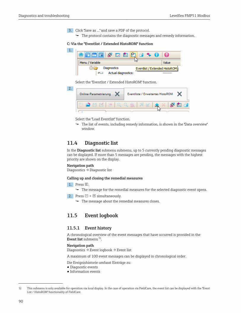
Diagnostics and troubleshooting Levelflex FMP51 Modbus
90
3. Click "Save as ..." and save a PDF of the protocol.The protocol contains the diagnostic messages and remedy information.
C: Via the "Eventlist / Extended HistoROM" function1.
Select the "Eventlist / Extended HistoROM" function.
2.
Select the "Load Eventlist" function.The list of events, including remedy information, is shown in the "Data overview"window.
11.4 Diagnostic listIn the Diagnostic list submenu submenu, up to 5 currently pending diagnostic messagescan be displayed. If more than 5 messages are pending, the messages with the highestpriority are shown on the display.
Navigation pathDiagnostics → Diagnostic list
Calling up and closing the remedial measures1. Press .
The message for the remedial measures for the selected diagnostic event opens.
2. Press + simultaneously.The message about the remedial measures closes.
11.5 Event logbook
11.5.1 Event historyA chronological overview of the event messages that have occurred is provided in theEvent list submenu 5).
Navigation pathDiagnostics → Event logbook → Event list
A maximum of 100 event messages can be displayed in chronological order.
Die Ereignishistorie umfasst Einträge zu:• Diagnostic events• Information events
5) This submenu is only available for operation via local display. In the case of operation via FieldCare, the event list can be displayed with the "EventList / HistoROM" functionality of FieldCare.
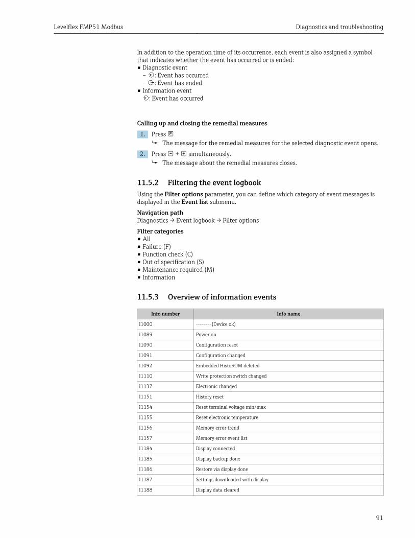
Levelflex FMP51 Modbus Diagnostics and troubleshooting
91
In addition to the operation time of its occurrence, each event is also assigned a symbolthat indicates whether the event has occurred or is ended:• Diagnostic event
– : Event has occurred– : Event has ended
• Information event: Event has occurred
Calling up and closing the remedial measures1. Press
The message for the remedial measures for the selected diagnostic event opens.
2. Press + simultaneously.The message about the remedial measures closes.
11.5.2 Filtering the event logbookUsing the Filter options parameter, you can define which category of event messages isdisplayed in the Event list submenu.
Navigation pathDiagnostics → Event logbook → Filter options
Filter categories• All• Failure (F)• Function check (C)• Out of specification (S)• Maintenance required (M)• Information
11.5.3 Overview of information events
Info number Info name
I1000 --------(Device ok)
I1089 Power on
I1090 Configuration reset
I1091 Configuration changed
I1092 Embedded HistoROM deleted
I1110 Write protection switch changed
I1137 Electronic changed
I1151 History reset
I1154 Reset terminal voltage min/max
I1155 Reset electronic temperature
I1156 Memory error trend
I1157 Memory error event list
I1184 Display connected
I1185 Display backup done
I1186 Restore via display done
I1187 Settings downloaded with display
I1188 Display data cleared
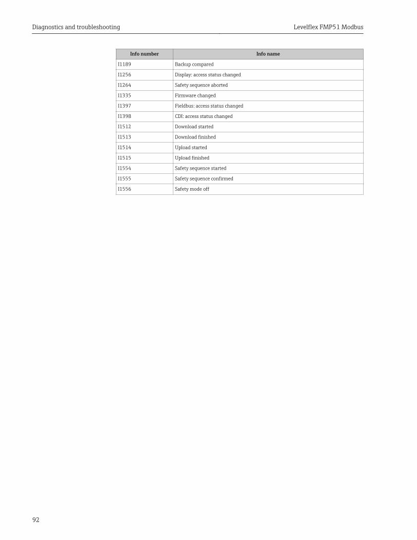
Diagnostics and troubleshooting Levelflex FMP51 Modbus
92
Info number Info name
I1189 Backup compared
I1256 Display: access status changed
I1264 Safety sequence aborted
I1335 Firmware changed
I1397 Fieldbus: access status changed
I1398 CDI: access status changed
I1512 Download started
I1513 Download finished
I1514 Upload started
I1515 Upload finished
I1554 Safety sequence started
I1555 Safety sequence confirmed
I1556 Safety mode off
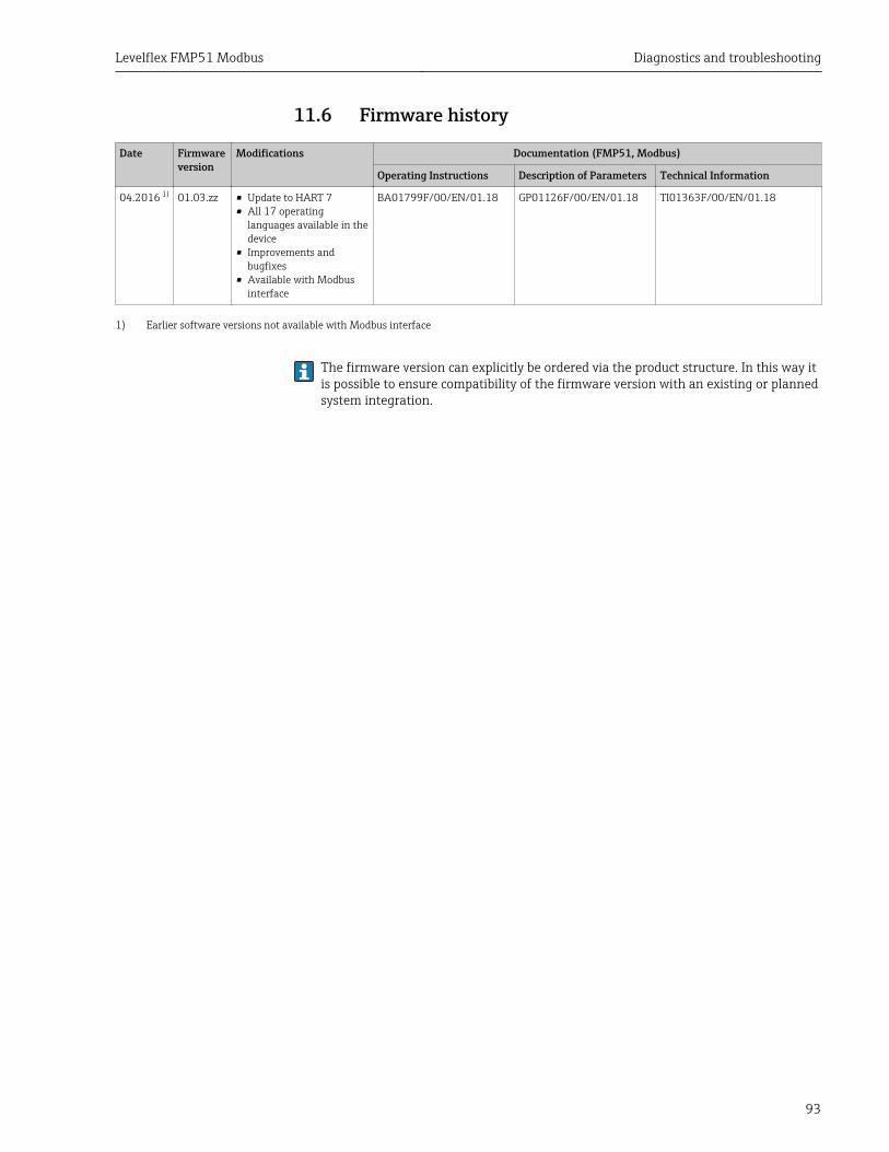
Levelflex FMP51 Modbus Diagnostics and troubleshooting
93
11.6 Firmware history
Date Firmwareversion
Modifications Documentation (FMP51, Modbus)
Operating Instructions Description of Parameters Technical Information
04.2016 1) 01.03.zz • Update to HART 7• All 17 operating
languages available in thedevice
• Improvements andbugfixes
• Available with Modbusinterface
BA01799F/00/EN/01.18 GP01126F/00/EN/01.18 TI01363F/00/EN/01.18
1) Earlier software versions not available with Modbus interface
The firmware version can explicitly be ordered via the product structure. In this way itis possible to ensure compatibility of the firmware version with an existing or plannedsystem integration.

Maintenance Levelflex FMP51 Modbus
94
12 MaintenanceThe measuring device requires no special maintenance.
12.1 Exterior cleaningWhen exterior-cleaning the device, always use cleaning agents that do not attack thesurface of the hosuing and the seals.
Levelflex FMP51 Modbus Repairs
95
13 Repairs
13.1 General information on repairs
13.1.1 Repairs to Ex-approved devicesWhen carrying out repairs to Ex-approved devices, please note the following:
• Repairs to Ex-approved devices may only be carried out by trained personnel.• Comply with the prevailing standards, national Ex-area regulations, safety instructions
(XA) and certificates.• Only use original spare parts.• When ordering a spare part, please note the device designation on the nameplate. Only
replace parts with identical parts.• Carry out repairs according to the instructions. On completion of repairs, carry out the
specified routine test on the device.• It is not allowed to convert a certified device into a different certified variant.• Document all repair work.
13.1.2 Replacement of an electronics moduleIf an electronics module has been replaced, it is not necessary to perform a new basic setupas the calibration parameters are stored in the HistoROM which is located in the housing.However, after exchanging the main electronics module it may be necessary to record anew mapping (interference echo suppression).
13.1.3 Replacement of a deviceAfter a complete device or electronic module has been replaced, the parameters can bedownloaded into the instrument again in one of the following ways:
• Via the display moduleCondition: The configuration of the old device has been saved in the display module→ 174.
• Via FieldCareCondition: The configuration of the old device has been saved to the computer viaFieldCare.
You can continue to measure without carrying out a new setup. Only a linearization and atank map (interference echo suppression) have to be recorded again.
13.2 DisposalObserve the following notes during disposal:• Observe valid federal/national regulations.• Ensure proper separation and reuse of the device components.
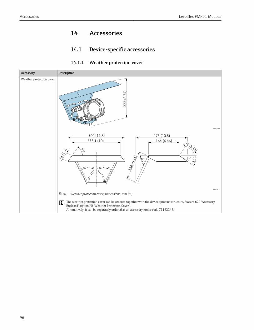
Accessories Levelflex FMP51 Modbus
96
14 Accessories
14.1 Device-specific accessories
14.1.1 Weather protection cover
Accessory Description
Weather protection cover
22
2 (
8.7
4)
A0015466
300 (11.8) 275 (10.8)
255.1 (10)
15
6(6
.14
)
38
(1.5
)
164 (6.46)54
(2.13)
35
°65
°
55
°
A0015472
20 Weather protection cover; Dimensions: mm (in)
The weather protection cover can be ordered together with the device (product structure, feature 620 "AccessoryEnclosed", option PB "Weather Protection Cover").Alternatively, it can be separately ordered as an accessory; order code 71162242.
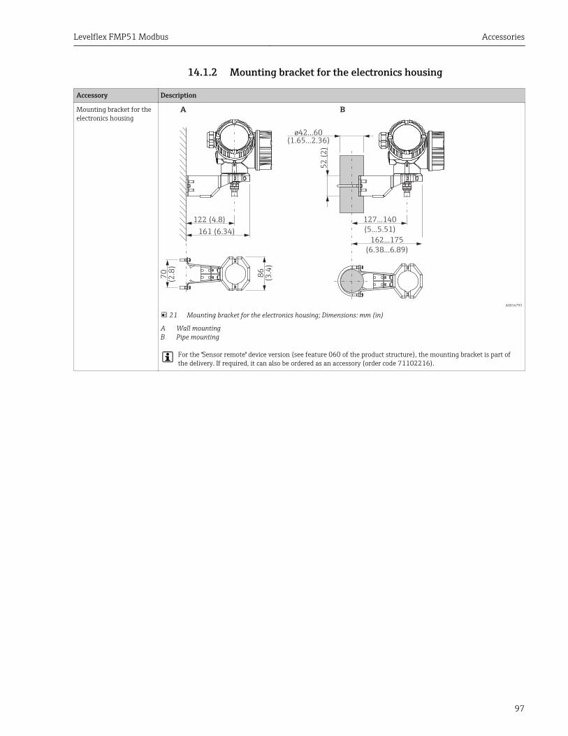
Levelflex FMP51 Modbus Accessories
97
14.1.2 Mounting bracket for the electronics housing
Accessory Description
Mounting bracket for theelectronics housing
122 (4.8)
52
(2
)
86
(3.4
)
70
(2.8
)
127...140
(5...5.51)161 (6.34)
162...175
(6.38...6.89)
A B
ø42...60
(1.65...2.36)
A0014793
21 Mounting bracket for the electronics housing; Dimensions: mm (in)
A Wall mountingB Pipe mounting
For the "Sensor remote" device version (see feature 060 of the product structure), the mounting bracket is part ofthe delivery. If required, it can also be ordered as an accessory (order code 71102216).
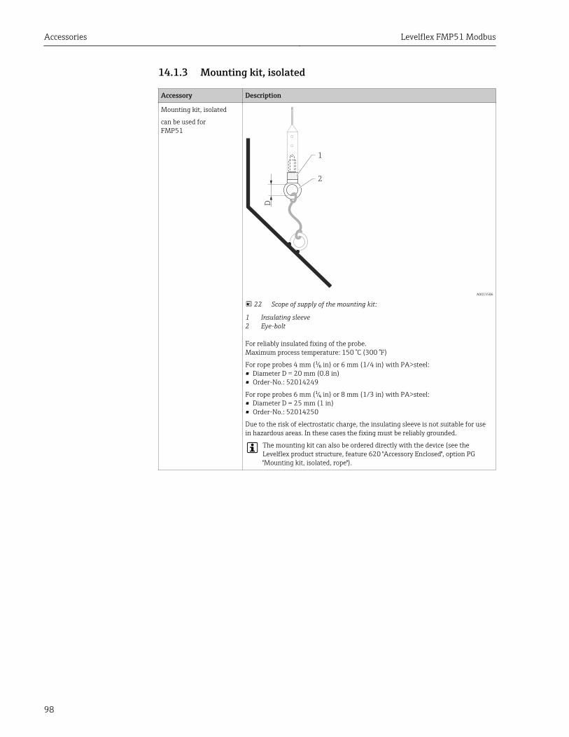
Accessories Levelflex FMP51 Modbus
98
14.1.3 Mounting kit, isolated
Accessory Description
Mounting kit, isolated
can be used forFMP51
D
1
2
A0013586
22 Scope of supply of the mounting kit:
1 Insulating sleeve2 Eye-bolt
For reliably insulated fixing of the probe.Maximum process temperature: 150 °C (300 °F)
For rope probes 4 mm (¹⁄₆ in) or 6 mm (1/4 in) with PA>steel:• Diameter D = 20 mm (0.8 in)• Order-No.: 52014249
For rope probes 6 mm (¹⁄₄ in) or 8 mm (1/3 in) with PA>steel:• Diameter D = 25 mm (1 in)• Order-No.: 52014250
Due to the risk of electrostatic charge, the insulating sleeve is not suitable for usein hazardous areas. In these cases the fixing must be reliably grounded.
The mounting kit can also be ordered directly with the device (see theLevelflex product structure, feature 620 "Accessory Enclosed", option PG"Mounting kit, isolated, rope").
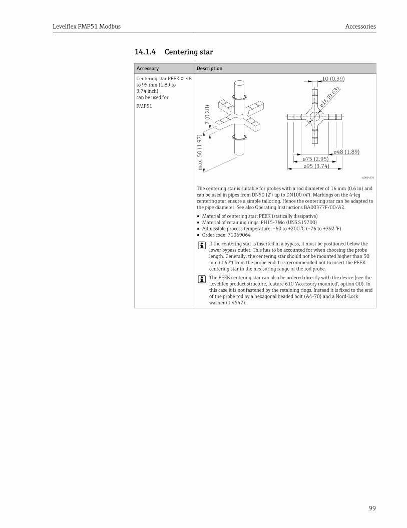
Levelflex FMP51 Modbus Accessories
99
14.1.4 Centering star
Accessory Description
Centering star PEEK 48to 95 mm (1.89 to3.74 inch)can be used for
FMP51
10 (0.39)
ø16
(0.6
3)
ø48 (1.89)
ø75 (2.95)
ø95 (3.74)
ma
x.
50
(1
.97
)
7 (
0.2
8)
A0014576
The centering star is suitable for probes with a rod diameter of 16 mm (0.6 in) andcan be used in pipes from DN50 (2") up to DN100 (4"). Markings on the 4-legcentering star ensure a simple tailoring. Hence the centering star can be adapted tothe pipe diameter. See also Operating Instructions BA00377F/00/A2.
• Material of centering star: PEEK (statically dissipative)• Material of retaining rings: PH15-7Mo (UNS S15700)• Admissible process temperature: –60 to +200 °C (–76 to +392 °F)• Order code: 71069064
If the centering star is inserted in a bypass, it must be positioned below thelower bypass outlet. This has to be accounted for when choosing the probelength. Generally, the centering star should not be mounted higher than 50 mm (1.97") from the probe end. It is recommended not to insert the PEEKcentering star in the measuring range of the rod probe.
The PEEK centering star can also be ordered directly with the device (see theLevelflex product structure, feature 610 "Accessory mounted", option OD). Inthis case it is not fastened by the retaining rings. Instead it is fixed to the endof the probe rod by a hexagonal headed bolt (A4-70) and a Nord-Lockwasher (1.4547).
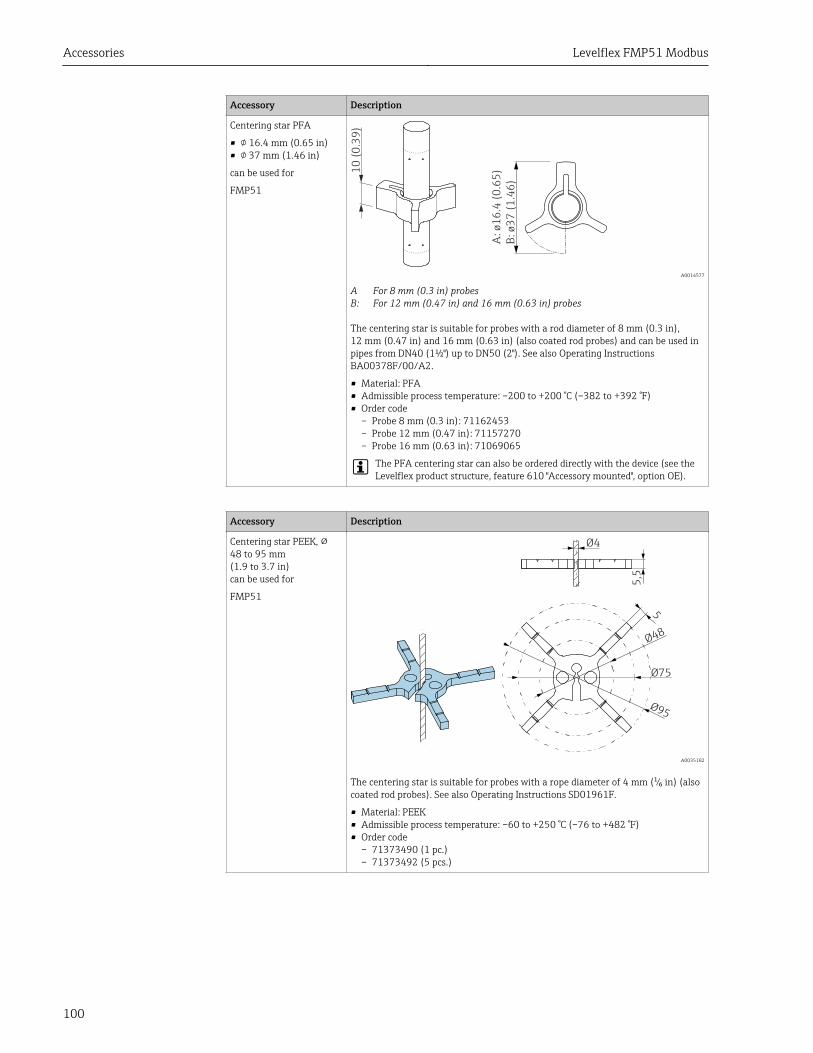
Accessories Levelflex FMP51 Modbus
100
Accessory Description
Centering star PFA
• 16.4 mm (0.65 in)• 37 mm (1.46 in)
can be used for
FMP51
10
(0
.39
)
A:
ø1
6.4
(0
.65
)
B:
ø3
7 (
1.4
6)
A0014577
A For 8 mm (0.3 in) probesB: For 12 mm (0.47 in) and 16 mm (0.63 in) probes
The centering star is suitable for probes with a rod diameter of 8 mm (0.3 in),12 mm (0.47 in) and 16 mm (0.63 in) (also coated rod probes) and can be used inpipes from DN40 (1½") up to DN50 (2"). See also Operating InstructionsBA00378F/00/A2.
• Material: PFA• Admissible process temperature: –200 to +200 °C (–382 to +392 °F)• Order code
– Probe 8 mm (0.3 in): 71162453– Probe 12 mm (0.47 in): 71157270– Probe 16 mm (0.63 in): 71069065
The PFA centering star can also be ordered directly with the device (see theLevelflex product structure, feature 610 "Accessory mounted", option OE).
Accessory Description
Centering star PEEK, ⌀48 to 95 mm(1.9 to 3.7 in)can be used for
FMP51
Ø4
5,5
5
Ø48
Ø75
Ø95
A0035182
The centering star is suitable for probes with a rope diameter of 4 mm (¹⁄₆ in) (alsocoated rod probes). See also Operating Instructions SD01961F.
• Material: PEEK• Admissible process temperature: –60 to +250 °C (–76 to +482 °F)• Order code
– 71373490 (1 pc.)– 71373492 (5 pcs.)
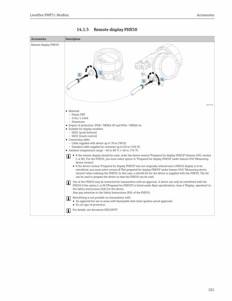
Levelflex FMP51 Modbus Accessories
101
14.1.5 Remote display FHX50
Accessories Description
Remote display FHX50
1.2.
3.4.
A0019128
• Material:– Plastic PBT– 316L/1.4404– Aluminum
• Degree of protection: IP68 / NEMA 6P and IP66 / NEMA 4x• Suitable for display modules:
– SD02 (push buttons)– SD03 (touch control)
• Connecting cable:– Cable supplied with device up to 30 m (98 ft)– Standard cable supplied by customer up to 60 m (196 ft)
• Ambient temperature range: –40 to 80 °C (–40 to 176 °F)
• If the remote display should be used, order the device version "Prepared for display FHX50" (feature 030, versionL or M). For the FHX50, you must select option A: "Prepared for display FHX50" under feature 050 "Measuringdevice version".
• If the device version "Prepared for display FHX50" was not originally ordered and a FHX50 display is to beretrofitted, you must select version B "Not prepared for display FHX50" under feature 050: "Measuring deviceversion" when ordering the FHX50. In this case, a retrofit kit for the device is supplied with the FHX50. The kitcan be used to prepare the device so that the FHX50 can be used.
Use of the FHX50 may be restricted for transmitters with an approval. A device can only be retrofitted with theFHX50 if the option L or M ("Prepared for FHX50") is listed under Basic specifications, item 4 "Display, operation" inthe Safety Instructions (XA) for the device.Also pay attention to the Safety Instructions (XA) of the FHX50.
Retrofitting is not possible on transmitters with:• An approval for use in areas with flammable dust (dust ignition-proof approval)• Ex nA type of protection
For details, see document SD01007F.
Accessories Levelflex FMP51 Modbus
102
14.2 Communication-specific accessories
Accessory Description
Commubox FXA291 Connects field devices with CDI interface to the USB interface of a computer.Order code: 51516983
14.3 Service-specific accessories
Accessory Description
DeviceCare SFE100 Configuration tool for HART, PROFIBUS and FOUNDATION Fieldbus devices
Technical Information TI01134S
FieldCare SFE500 FDT-based Plant Asset Management tool.Helps to configure and maintain all field devices of your plant. By supplying statusinformation it also supports the diagnosis of the devices.
Technical Information TI00028S
14.4 System components
Accessory Description
Graphic Data ManagerMemograph M
The graphic data manager Memograph M provides information on all the relevantprocess variables. Measured values are recorded correctly, limit values aremonitored and measuring points analyzed. The data are stored in the 256 MBinternal memory and also on an SD card or USB stick.
For details refer to Technical Information TI00133R and OperatingInstructions BA00247R
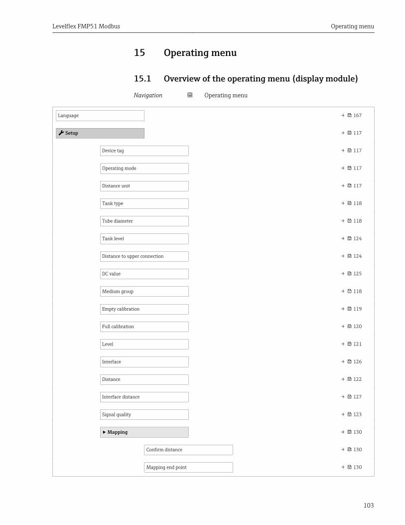
Levelflex FMP51 Modbus Operating menu
103
15 Operating menu
15.1 Overview of the operating menu (display module)
Navigation Operating menu
Language → 167
Setup → 117
Device tag → 117
Operating mode → 117
Distance unit → 117
Tank type → 118
Tube diameter → 118
Tank level → 124
Distance to upper connection → 124
DC value → 125
Medium group → 118
Empty calibration → 119
Full calibration → 120
Level → 121
Interface → 126
Distance → 122
Interface distance → 127
Signal quality → 123
‣ Mapping → 130
Confirm distance → 130
Mapping end point → 130
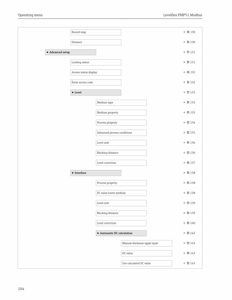
Operating menu Levelflex FMP51 Modbus
104
Record map → 130
Distance → 130
‣ Advanced setup → 131
Locking status → 131
Access status display → 132
Enter access code → 132
‣ Level → 133
Medium type → 133
Medium property → 133
Process property → 134
Advanced process conditions → 135
Level unit → 136
Blocking distance → 136
Level correction → 137
‣ Interface → 138
Process property → 138
DC value lower medium → 138
Level unit → 139
Blocking distance → 139
Level correction → 140
‣ Automatic DC calculation → 143
Manual thickness upper layer → 143
DC value → 143
Use calculated DC value → 143
Levelflex FMP51 Modbus Operating menu
105
‣ Linearization → 145
Linearization type → 147
Unit after linearization → 148
Free text → 149
Maximum value → 150
Diameter → 150
Intermediate height → 151
Table mode → 151
‣ Edit table
Level → 153
Customer value → 153
Activate table → 153
‣ Safety settings → 155
Output echo lost → 155
Value echo lost → 155
Ramp at echo lost → 156
Blocking distance → 136
‣ Probe settings → 158
Probe grounded → 158
‣ Probe length correction → 160
Confirm probe length → 160
Present probe length → 160
‣ Switch output → 161
Switch output function → 161
Assign status → 162
Operating menu Levelflex FMP51 Modbus
106
Assign limit → 162
Assign diagnostic behavior → 162
Switch-on value → 163
Switch-on delay → 164
Switch-off value → 164
Switch-off delay → 165
Failure mode → 165
Switch status → 165
Invert output signal → 165
‣ Display → 167
Language → 167
Format display → 167
Value 1 to 4 display → 169
Decimal places 1 to 4 → 169
Display interval → 170
Display damping → 170
Header → 170
Header text → 171
Separator → 171
Number format → 171
Decimal places menu → 172
Backlight → 172
Contrast display → 173
‣ Configuration backup display → 174
Operating time → 174
Levelflex FMP51 Modbus Operating menu
107
Last backup → 174
Configuration management → 174
Comparison result → 175
‣ Administration → 177
‣ Define access code → 179
Define access code → 179
Confirm access code → 179
Device reset → 177
Diagnostics → 180
Actual diagnostics → 180
Previous diagnostics → 180
Operating time from restart → 181
Operating time → 174
‣ Diagnostic list → 182
Diagnostics 1 to 5 → 182
‣ Event logbook → 183
Filter options → 183
‣ Event list → 183
‣ Device information → 184
Device tag → 184
Serial number → 184
Firmware version → 184
Device name → 184
Order code → 185
Extended order code 1 to 3 → 185
Operating menu Levelflex FMP51 Modbus
108
Device revision → 185
Device ID → 185
Device type → 186
Manufacturer ID → 186
‣ Measured values → 187
Distance → 122
Level linearized → 149
Interface distance → 127
Interface linearized → 150
Thickness upper layer → 189
Terminal voltage 1 → 189
‣ Data logging → 190
Assign channel 1 to 4 → 190
Logging interval → 191
Clear logging data → 191
‣ Display channel 1 to 4 → 192
‣ Simulation → 194
Assign measurement variable → 195
Process variable value → 195
Switch output simulation → 195
Switch status → 196
Device alarm simulation → 196
‣ Device check → 197
Start device check → 197
Result device check → 197

Levelflex FMP51 Modbus Operating menu
109
Last check time → 197
Level signal → 198
Launch signal → 198
Interface signal → 198
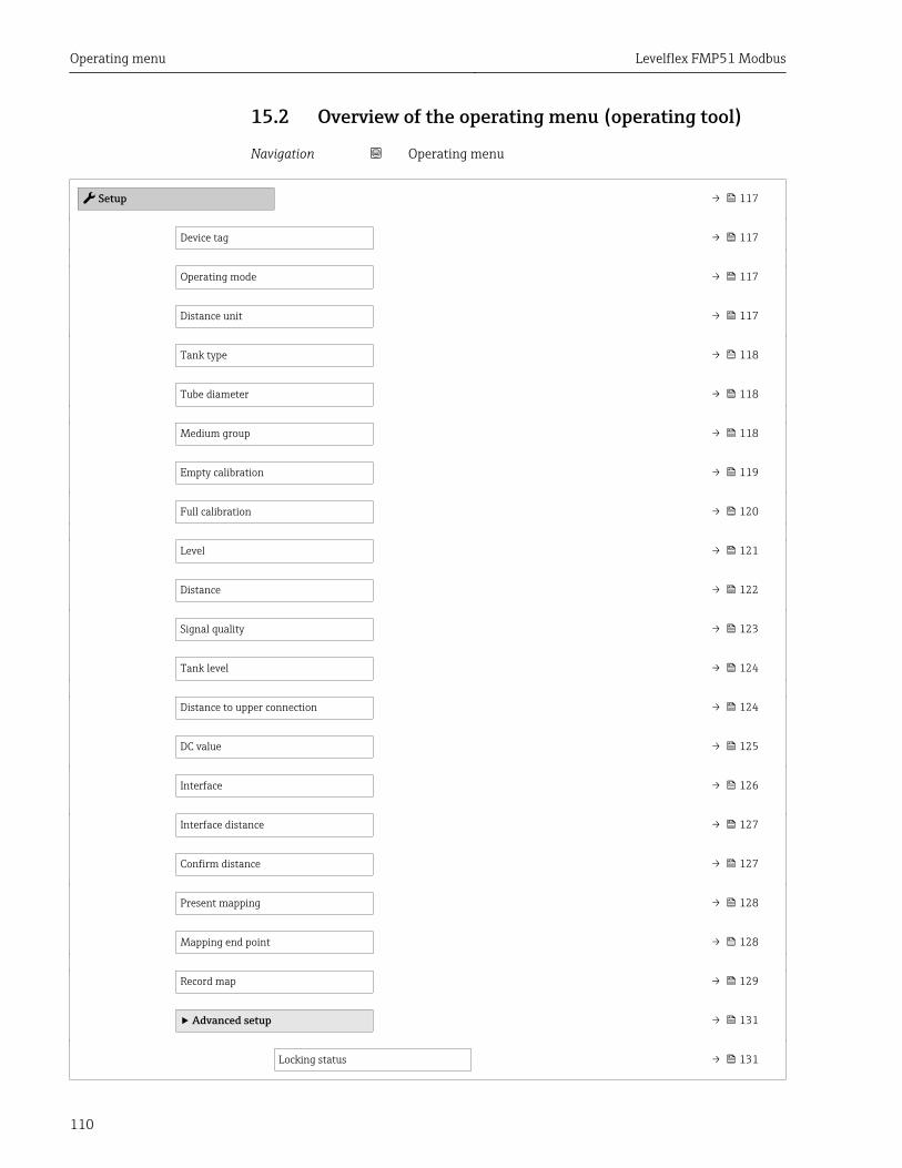
Operating menu Levelflex FMP51 Modbus
110
15.2 Overview of the operating menu (operating tool)
Navigation Operating menu
Setup → 117
Device tag → 117
Operating mode → 117
Distance unit → 117
Tank type → 118
Tube diameter → 118
Medium group → 118
Empty calibration → 119
Full calibration → 120
Level → 121
Distance → 122
Signal quality → 123
Tank level → 124
Distance to upper connection → 124
DC value → 125
Interface → 126
Interface distance → 127
Confirm distance → 127
Present mapping → 128
Mapping end point → 128
Record map → 129
‣ Advanced setup → 131
Locking status → 131
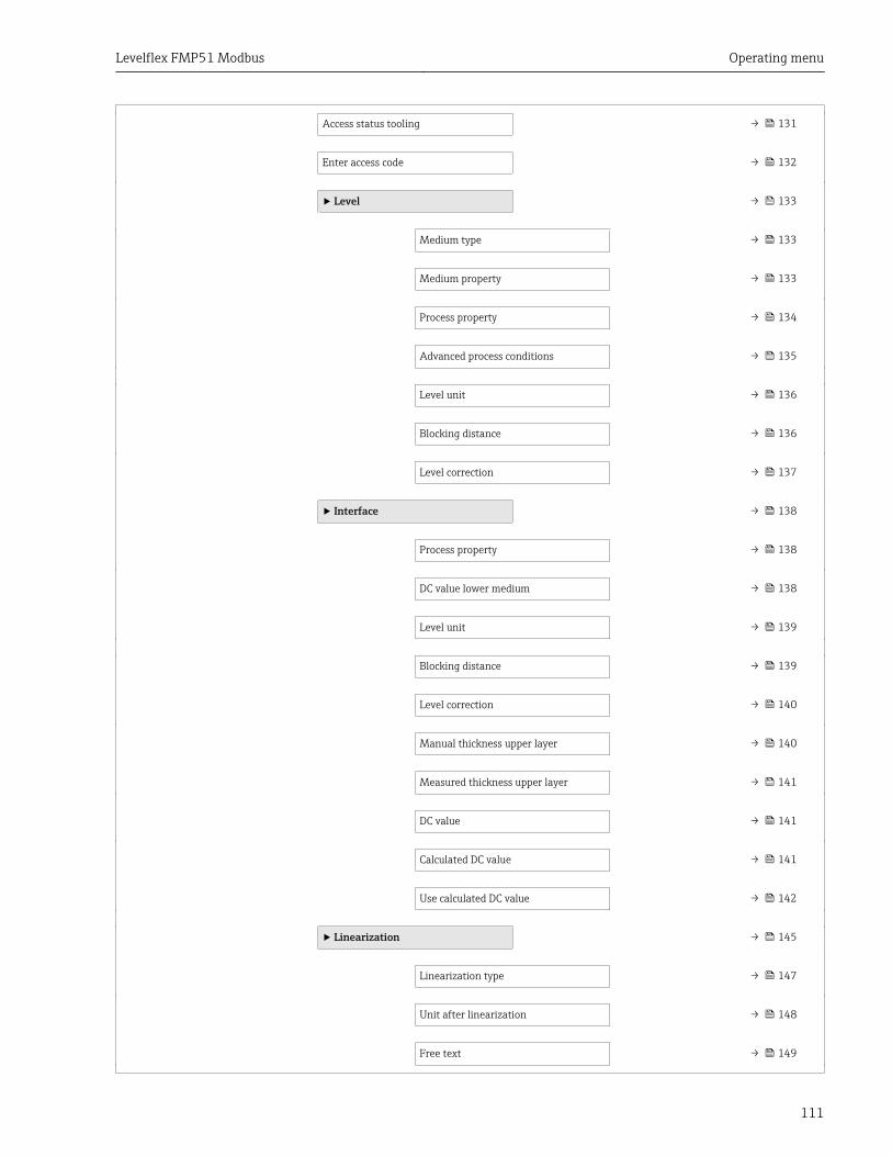
Levelflex FMP51 Modbus Operating menu
111
Access status tooling → 131
Enter access code → 132
‣ Level → 133
Medium type → 133
Medium property → 133
Process property → 134
Advanced process conditions → 135
Level unit → 136
Blocking distance → 136
Level correction → 137
‣ Interface → 138
Process property → 138
DC value lower medium → 138
Level unit → 139
Blocking distance → 139
Level correction → 140
Manual thickness upper layer → 140
Measured thickness upper layer → 141
DC value → 141
Calculated DC value → 141
Use calculated DC value → 142
‣ Linearization → 145
Linearization type → 147
Unit after linearization → 148
Free text → 149
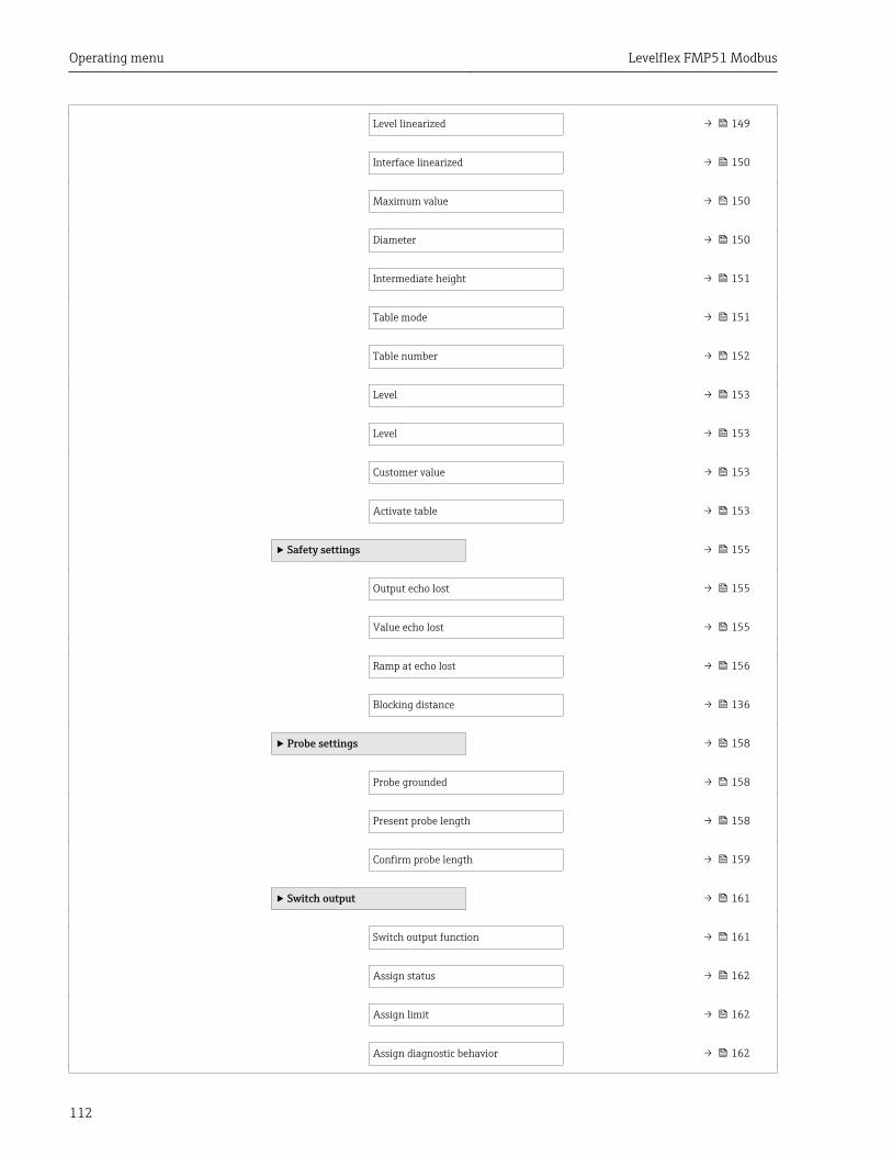
Operating menu Levelflex FMP51 Modbus
112
Level linearized → 149
Interface linearized → 150
Maximum value → 150
Diameter → 150
Intermediate height → 151
Table mode → 151
Table number → 152
Level → 153
Level → 153
Customer value → 153
Activate table → 153
‣ Safety settings → 155
Output echo lost → 155
Value echo lost → 155
Ramp at echo lost → 156
Blocking distance → 136
‣ Probe settings → 158
Probe grounded → 158
Present probe length → 158
Confirm probe length → 159
‣ Switch output → 161
Switch output function → 161
Assign status → 162
Assign limit → 162
Assign diagnostic behavior → 162
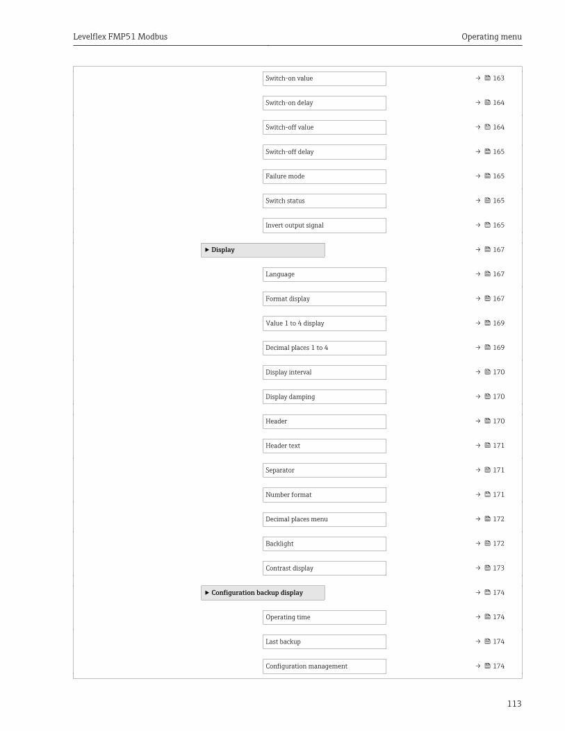
Levelflex FMP51 Modbus Operating menu
113
Switch-on value → 163
Switch-on delay → 164
Switch-off value → 164
Switch-off delay → 165
Failure mode → 165
Switch status → 165
Invert output signal → 165
‣ Display → 167
Language → 167
Format display → 167
Value 1 to 4 display → 169
Decimal places 1 to 4 → 169
Display interval → 170
Display damping → 170
Header → 170
Header text → 171
Separator → 171
Number format → 171
Decimal places menu → 172
Backlight → 172
Contrast display → 173
‣ Configuration backup display → 174
Operating time → 174
Last backup → 174
Configuration management → 174
Operating menu Levelflex FMP51 Modbus
114
Backup state → 175
Comparison result → 175
‣ Administration → 177
Define access code → 179
Device reset → 177
Diagnostics → 180
Actual diagnostics → 180
Timestamp → 180
Previous diagnostics → 180
Timestamp → 181
Operating time from restart → 181
Operating time → 174
‣ Diagnostic list → 182
Diagnostics 1 to 5 → 182
Timestamp 1 to 5 → 182
‣ Device information → 184
Device tag → 184
Serial number → 184
Firmware version → 184
Device name → 184
Order code → 185
Extended order code 1 to 3 → 185
Device revision → 185
Device ID → 185
Levelflex FMP51 Modbus Operating menu
115
Device type → 186
Manufacturer ID → 186
‣ Measured values → 187
Distance → 122
Level linearized → 149
Interface distance → 127
Interface linearized → 150
Thickness upper layer → 189
Terminal voltage 1 → 189
‣ Data logging → 190
Assign channel 1 to 4 → 190
Logging interval → 191
Clear logging data → 191
‣ Simulation → 194
Assign measurement variable → 195
Process variable value → 195
Switch output simulation → 195
Switch status → 196
Device alarm simulation → 196
‣ Device check → 197
Start device check → 197
Result device check → 197
Last check time → 197
Level signal → 198

Operating menu Levelflex FMP51 Modbus
116
Launch signal → 198
Interface signal → 198
‣ Heartbeat
Levelflex FMP51 Modbus Operating menu
117
15.3 "Setup" menu• : Marks the navigation path to the parameter via the display and operating
module.• : Marks the navigation path to the parameter via an operating tool (e.g.
FieldCare).• : Marks parameters which can be locked via the software locking → 60.
Navigation Setup
Device tag
Navigation Setup → Device tag
Description Enter a unique name for the measuring point to identify the device quickly within theplant.
Factory setting FMP5x
Operating mode
Navigation Setup → Operating mode
Prerequisite The device has the "interface measurement" application package 6).
Description Select operating mode.
Selection • Level• Interface with capacitance *
• Interface *
Factory setting Level
Distance unit
Navigation Setup → Distance unit
Description Used for the basic calibration (Empty / Full).
Selection SI units• mm• m
US units• ft• in
6) Product structure: Feature 540 "Application Package", Option EB "Interface measurement"* Visibility depends on order options or device settings
Operating menu Levelflex FMP51 Modbus
118
Factory setting m
Tank type
Navigation Setup → Tank type
Prerequisite Medium type (→ 133) = Liquid
Description Select tank type.
Selection • Metallic• Bypass / pipe• Non metallic• Mounted outside• Coaxial
Factory setting Metallic
Additional information
Tube diameter
Navigation Setup → Tube diameter
Prerequisite Tank type (→ 118) = Bypass / pipe
Description Specify diameter of bypass or stilling well.
User entry 0 to 9.999 m
Factory setting 0.0384 m
Medium group
Navigation Setup → Medium group
Prerequisite Medium type (→ 133) = Liquid
Description Select medium group.
Selection • Others• Water based (DC >= 4)
Factory setting Others
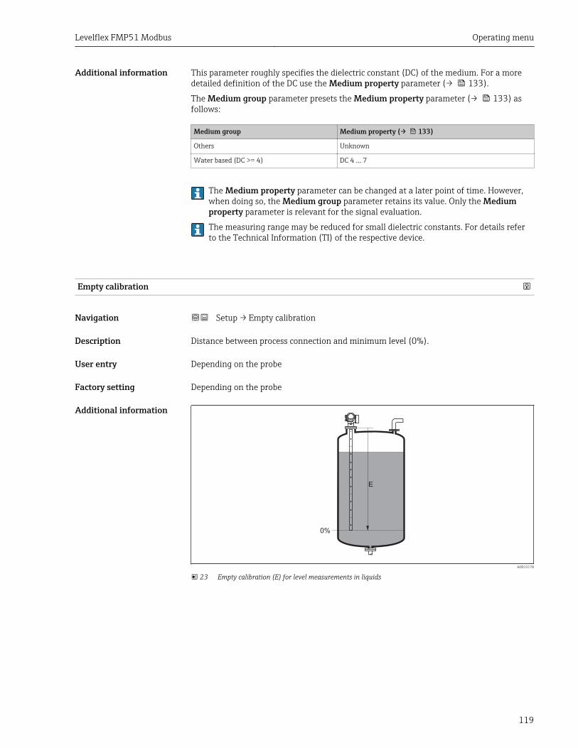
Levelflex FMP51 Modbus Operating menu
119
Additional information This parameter roughly specifies the dielectric constant (DC) of the medium. For a moredetailed definition of the DC use the Medium property parameter (→ 133).
The Medium group parameter presets the Medium property parameter (→ 133) asfollows:
Medium group Medium property (→ 133)
Others Unknown
Water based (DC >= 4) DC 4 ... 7
The Medium property parameter can be changed at a later point of time. However,when doing so, the Medium group parameter retains its value. Only the Mediumproperty parameter is relevant for the signal evaluation.
The measuring range may be reduced for small dielectric constants. For details referto the Technical Information (TI) of the respective device.
Empty calibration
Navigation Setup → Empty calibration
Description Distance between process connection and minimum level (0%).
User entry Depending on the probe
Factory setting Depending on the probe
Additional information
0%
E
A0013178
23 Empty calibration (E) for level measurements in liquids
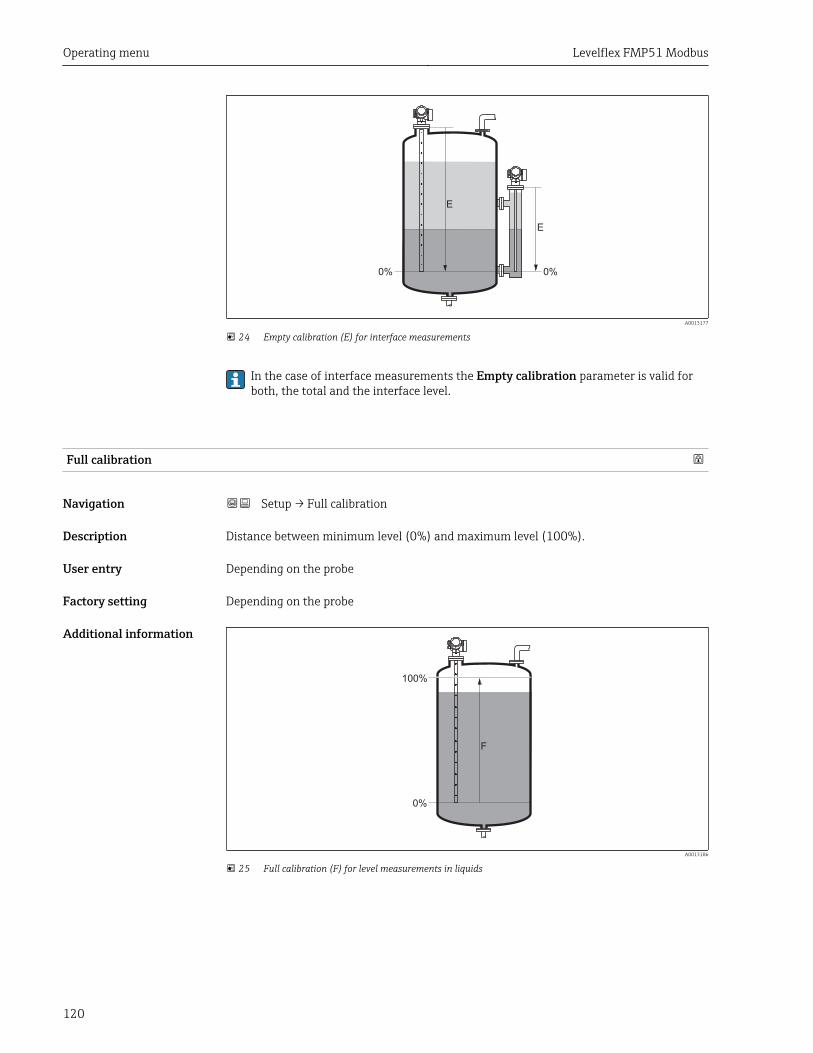
Operating menu Levelflex FMP51 Modbus
120
0%
E
E
0%
A0013177
24 Empty calibration (E) for interface measurements
In the case of interface measurements the Empty calibration parameter is valid forboth, the total and the interface level.
Full calibration
Navigation Setup → Full calibration
Description Distance between minimum level (0%) and maximum level (100%).
User entry Depending on the probe
Factory setting Depending on the probe
Additional information
0%
F
100%
A0013186
25 Full calibration (F) for level measurements in liquids

Levelflex FMP51 Modbus Operating menu
121
0%
F
F
0%
100%
100%
A0013188
26 Full calibration (F) for interface measurements
In the case of interface measurements the Full calibration parameter is valid forboth, the total and the interface level.
Level
Navigation Setup → Level
Description Displays measured level LL (before linearization).
Additional information
0%
LL
A0013194
27 Level in case of liquid measurements
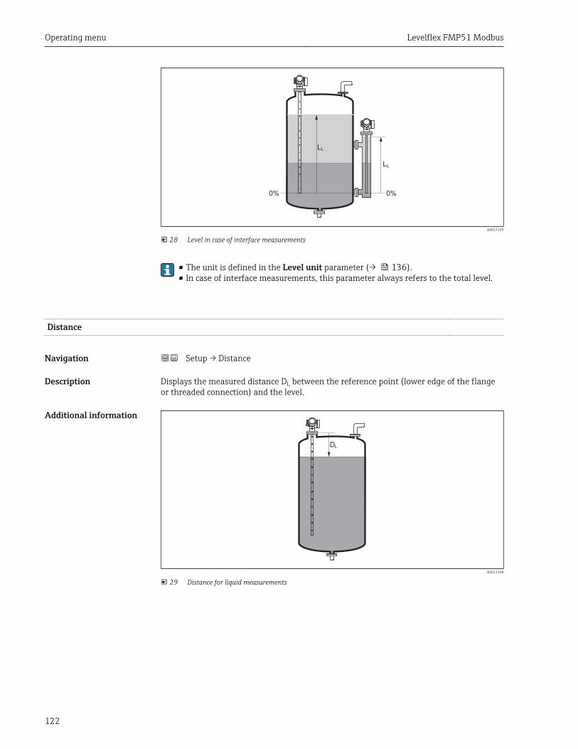
Operating menu Levelflex FMP51 Modbus
122
0%
L
0%
L
LL
A0013195
28 Level in case of interface measurements
• The unit is defined in the Level unit parameter (→ 136).• In case of interface measurements, this parameter always refers to the total level.
Distance
Navigation Setup → Distance
Description Displays the measured distance DL between the reference point (lower edge of the flangeor threaded connection) and the level.
Additional information
DL
A0013198
29 Distance for liquid measurements
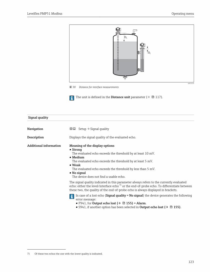
Levelflex FMP51 Modbus Operating menu
123
DL
DL
A0013199
30 Distance for interface measurements
The unit is defined in the Distance unit parameter (→ 117).
Signal quality
Navigation Setup → Signal quality
Description Displays the signal quality of the evaluated echo.
Additional information Meaning of the display options• Strong
The evaluated echo exceeds the threshold by at least 10 mV.• Medium
The evaluated echo exceeds the threshold by at least 5 mV.• Weak
The evaluated echo exceeds the threshold by less than 5 mV.• No signal
The device does not find a usable echo.
The signal quality indicated in this parameter always refers to the currently evaluatedecho: either the level/interface echo 7) or the end-of-probe echo. To differentiate betweenthese two, the quality of the end-of-probe echo is always displayed in brackets.
In case of a lost echo (Signal quality = No signal) the device generates the followingerror message:• F941, for Output echo lost (→ 155) = Alarm.• S941, if another option has been selected in Output echo lost (→ 155).
7) Of these two echos the one with the lower quality is indicated.
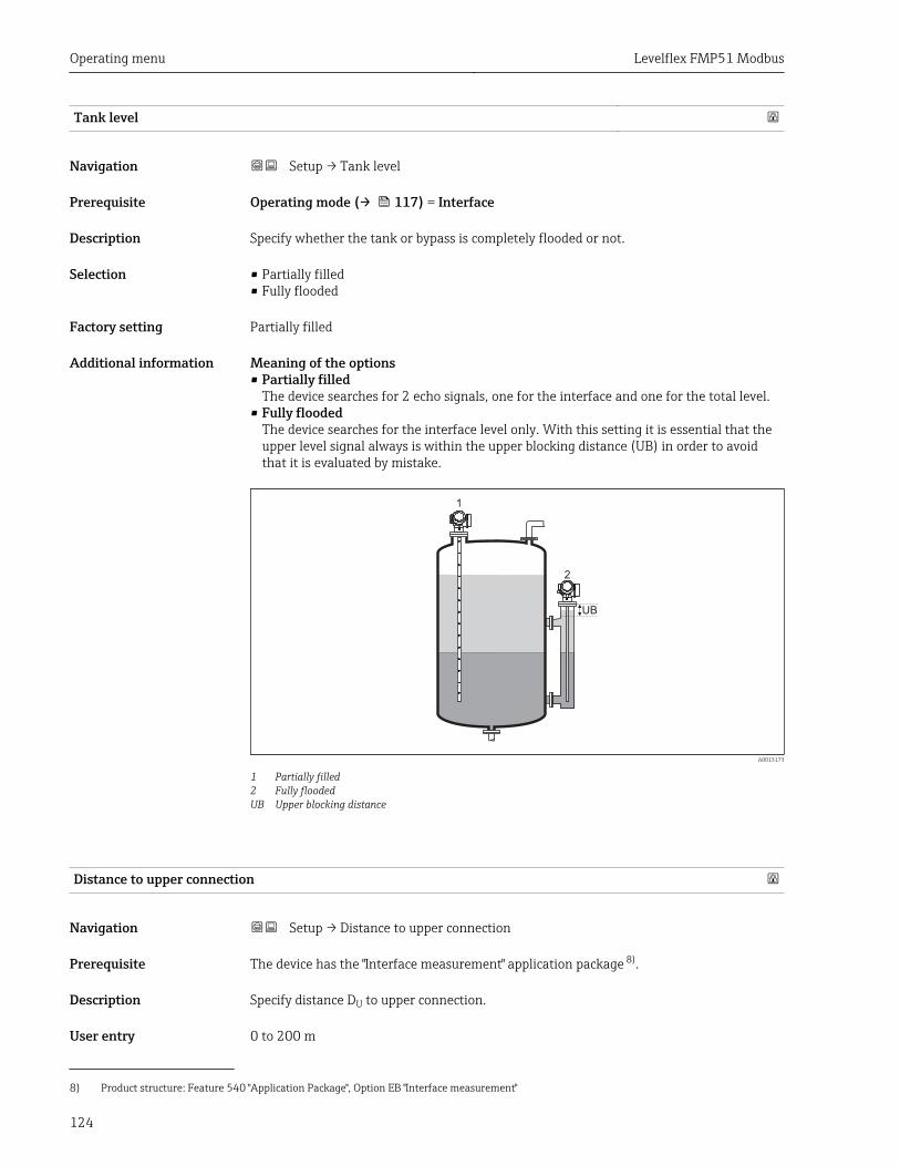
Operating menu Levelflex FMP51 Modbus
124
Tank level
Navigation Setup → Tank level
Prerequisite Operating mode (→ 117) = Interface
Description Specify whether the tank or bypass is completely flooded or not.
Selection • Partially filled• Fully flooded
Factory setting Partially filled
Additional information Meaning of the options• Partially filled
The device searches for 2 echo signals, one for the interface and one for the total level.• Fully flooded
The device searches for the interface level only. With this setting it is essential that theupper level signal always is within the upper blocking distance (UB) in order to avoidthat it is evaluated by mistake.
1
2
UB
A0013173
1 Partially filled2 Fully floodedUB Upper blocking distance
Distance to upper connection
Navigation Setup → Distance to upper connection
Prerequisite The device has the "Interface measurement" application package 8).
Description Specify distance DU to upper connection.
User entry 0 to 200 m
8) Product structure: Feature 540 "Application Package", Option EB "Interface measurement"
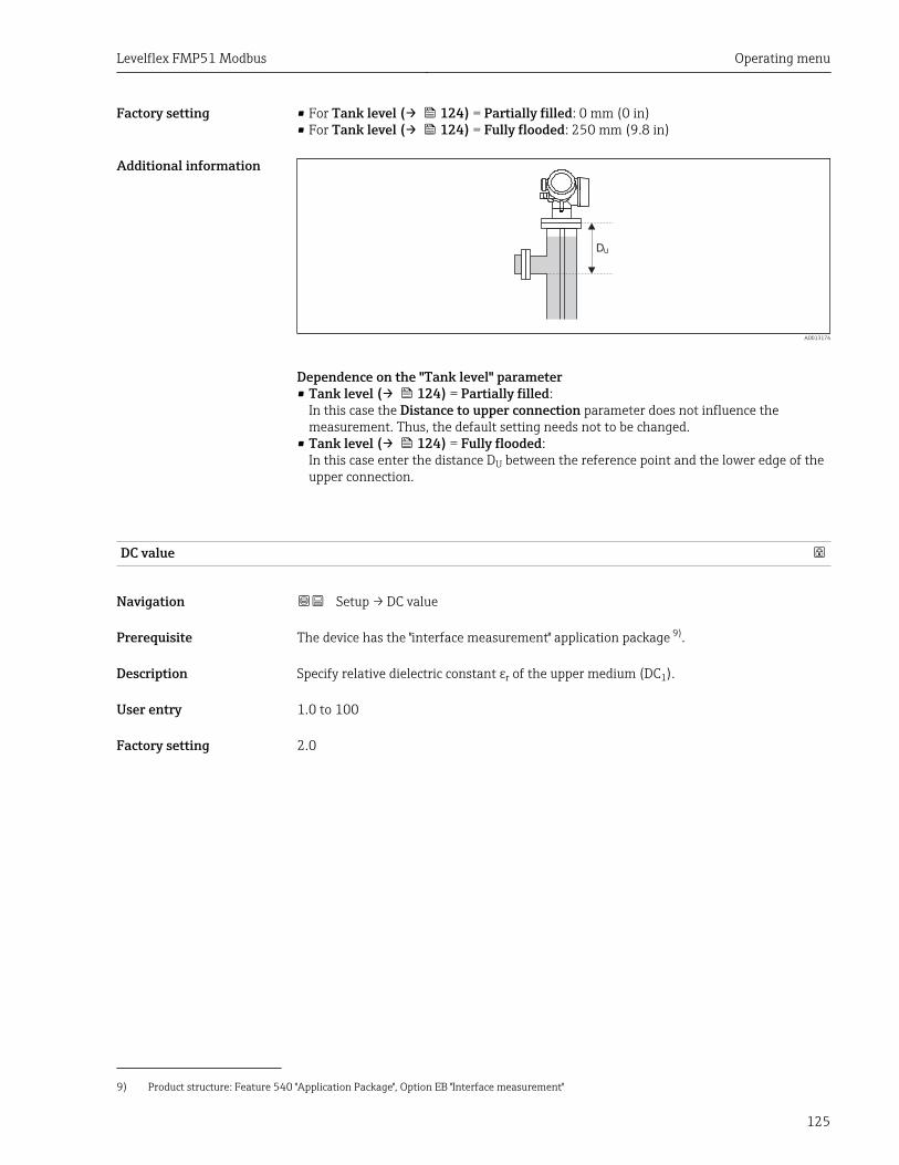
Levelflex FMP51 Modbus Operating menu
125
Factory setting • For Tank level (→ 124) = Partially filled: 0 mm (0 in)• For Tank level (→ 124) = Fully flooded: 250 mm (9.8 in)
Additional information
DU
A0013174
Dependence on the "Tank level" parameter• Tank level (→ 124) = Partially filled:
In this case the Distance to upper connection parameter does not influence themeasurement. Thus, the default setting needs not to be changed.
• Tank level (→ 124) = Fully flooded:In this case enter the distance DU between the reference point and the lower edge of theupper connection.
DC value
Navigation Setup → DC value
Prerequisite The device has the "interface measurement" application package 9).
Description Specify relative dielectric constant εr of the upper medium (DC1).
User entry 1.0 to 100
Factory setting 2.0
9) Product structure: Feature 540 "Application Package", Option EB "Interface measurement"
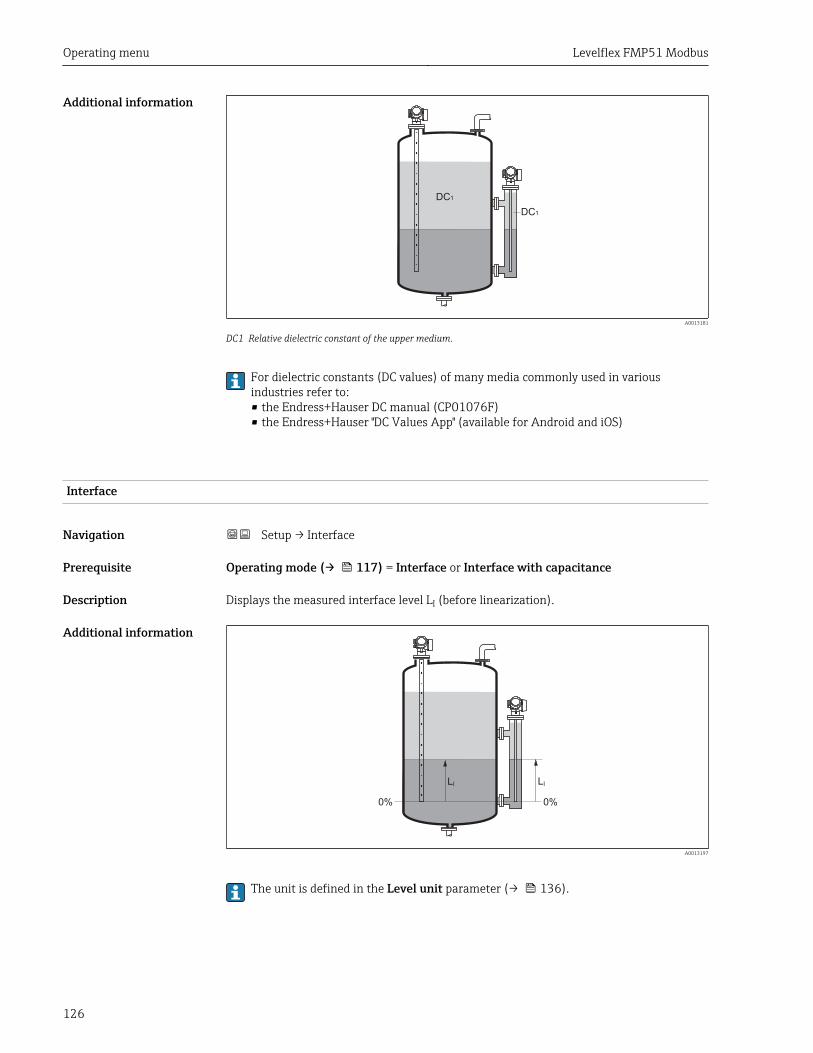
Operating menu Levelflex FMP51 Modbus
126
Additional information
DC 1
DC 1
A0013181
DC1 Relative dielectric constant of the upper medium.
For dielectric constants (DC values) of many media commonly used in variousindustries refer to:• the Endress+Hauser DC manual (CP01076F)• the Endress+Hauser "DC Values App" (available for Android and iOS)
Interface
Navigation Setup → Interface
Prerequisite Operating mode (→ 117) = Interface or Interface with capacitance
Description Displays the measured interface level LI (before linearization).
Additional information
0% 0%
L I L I
A0013197
The unit is defined in the Level unit parameter (→ 136).
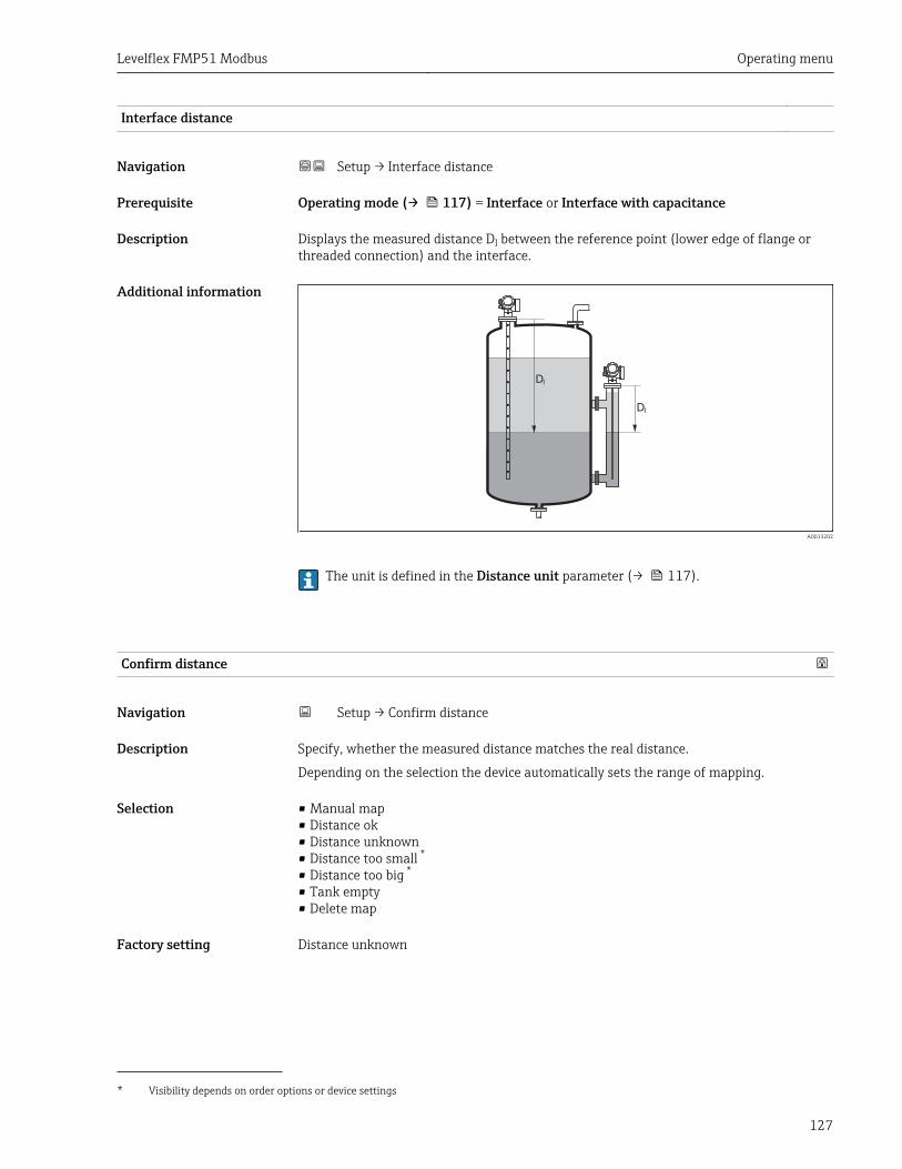
Levelflex FMP51 Modbus Operating menu
127
Interface distance
Navigation Setup → Interface distance
Prerequisite Operating mode (→ 117) = Interface or Interface with capacitance
Description Displays the measured distance DI between the reference point (lower edge of flange orthreaded connection) and the interface.
Additional information
DI
DI
A0013202
The unit is defined in the Distance unit parameter (→ 117).
Confirm distance
Navigation Setup → Confirm distance
Description Specify, whether the measured distance matches the real distance.
Depending on the selection the device automatically sets the range of mapping.
Selection • Manual map• Distance ok• Distance unknown• Distance too small *• Distance too big *
• Tank empty• Delete map
Factory setting Distance unknown
* Visibility depends on order options or device settings
Operating menu Levelflex FMP51 Modbus
128
Additional information Meaning of the options• Manual map
To be selected if the range of mapping is to be defined manually in the Mapping endpoint parameter (→ 128). In this case it is not necessary to confirm the distance.
• Distance okTo be selected if the measured distance matches the actual distance. The deviceperforms a mapping.
• Distance unknownTo be selected if the actual distance is unknown. A mapping can not be performed in thiscase.
• Distance too smallTo be selected if the measured distance is smaller than the actual distance. The devicesearches for the next echo and returns to the Confirm distance parameter. The distanceis recalculated and displayed. The comparison must be repeated until the displayeddistance matches the actual distance. After this, the recording of the map can be startedby selecting Distance ok.
• Distance too big 10)
To be selected if the measured distance exceeds the actual distance. The device adjuststhe signal evaluation and returns to the Confirm distance parameter. The distance isrecalculated and displayed. The comparison must be repeated until the displayeddistance matches the actual distance. After this, the recording of the map can be startedby selecting Distance ok.
• Tank emptyTo be selected if the tank is completely empty. The device records a mapping coveringthe complete measuring range.
• Factory mapTo be selected if the present mapping curve (if one exists) is to be deleted. The devicereturns to the Confirm distance parameter and a new mapping can be recorded.
When operating via the display module, the measured distance is displayed togetherwith this parameter for reference purposes.
For interface measurements the distance always refers to the toatal level (not theinterface level).
If the teaching procedure with the Distance too small option or the Distance too bigoption is quit before the distance has been confirmed, a map is not recorded and theteaching procedure is reset after 60 s.
Present mapping
Navigation Setup → Present mapping
Description Indicates up to which distance a mapping has already been recorded.
Mapping end point
Navigation Setup → Mapping end point
Prerequisite Confirm distance (→ 127) = Manual map or Distance too small
10) Only available for "Expert → Sensor → Echo tracking → Evaluation mode parameter" = "Short time history" or "Long time history"
Levelflex FMP51 Modbus Operating menu
129
Description Specify new end of the mapping.
User entry 0 to 200 000.0 m
Factory setting 0.1 m
Additional information This parameter defines up to which distance the new mapping is to be recorded. Thedistance is measured from the reference point, i.e. from the lower edge of the mountingflange or the threaded connection.
For reference purposes the Present mapping parameter (→ 128) is displayedtogether with this parameter. It indicates up to which distance a mapping has alreadybeen recorded.
Record map
Navigation Setup → Record map
Prerequisite Confirm distance (→ 127) = Manual map or Distance too small
Description Start recording of the map.
Selection • No• Record map• Delete map
Factory setting No
Additional information Meaning of the options• No
The map is not recorded.• Record map
The map is recorded. After the recording is completed, the new measured distance andthe new mapping range appear on the display. When operating via the local display,these values must be confirmed by pressing .
• Delete mapThe mapping (if one exists) is deleted and the device displays the recalculated measureddistance and the mapping range. When operating via the local display, these values mustbe confirmed by pressing .
Operating menu Levelflex FMP51 Modbus
130
15.3.1 "Mapping" wizardThe Mapping wizard is only available when operating via the local display. Whenoperating via an operating tool, all parameters concerning the mapping are locateddirectly in the Setup menu (→ 117).
In the Mapping wizard two parameters are displayed simultaneously on the displaymodule at any one time. The upper parameter can be edited, whereas the lowerparameter is displayed for reference purposes only.
Navigation Setup → Mapping
Confirm distance
Navigation Setup → Mapping → Confirm distance
Description → 127
Mapping end point
Navigation Setup → Mapping → Mapping end point
Description → 128
Record map
Navigation Setup → Mapping → Record map
Description → 129
Distance
Navigation Setup → Mapping → Distance
Description → 122
Levelflex FMP51 Modbus Operating menu
131
15.3.2 "Advanced setup" submenu
Navigation Setup → Advanced setup
Locking status
Navigation Setup → Advanced setup → Locking status
Description Indicates the write protection with the highest priority that is currently active.
User interface • Hardware locked• SIL locked• CT active - defined parameters• WHG locked• Temporarily locked
Additional information Meaning and priorities of the types of write protection• Hardware locked (priority 1)
The DIP switch for hardware locking is activated on the main electronics module. Thislocks write access to the parameters.
• SIL locked (priority 2)The SIL mode is activated. Writing access to the relevant parameters is denied.
• WHG locked (priority 3)The WHG mode is activated. Writing access to the relevant parameters is denied.
• Temporarily locked (priority 4)Write access to the parameters is temporarily locked on account of internal processes inprogress in the device (e.g. data upload/download, reset etc.). The parameters can bemodified as soon as the processes are complete.
On the display module, the -symbol appears in front of parameters that cannot bemodified since they are write-protected.
Access status tooling
Navigation Setup → Advanced setup → Access status tooling
Description Shows the access authorization to the parameters via the operating tool.
Additional information The access authorization can be changed via the Enter access code parameter(→ 132).
If additional write protection is active, this restricts the current access authorizationeven further. The write protection status can be viewed via the Locking statusparameter (→ 131).
Operating menu Levelflex FMP51 Modbus
132
Access status display
Navigation Setup → Advanced setup → Access status display
Prerequisite The device has a local display.
Description Indicates access authorization to parameters via local display.
Additional information The access authorization can be changed via the Enter access code parameter(→ 132).
If additional write protection is active, this restricts the current access authorizationeven further. The write protection status can be viewed via the Locking statusparameter (→ 131).
Enter access code
Navigation Setup → Advanced setup → Enter access code
Description Enter access code to disable write protection of parameters.
User entry 0 to 9 999
Additional information • For local operation, the customer-specific access code, which has been defined in theDefine access code parameter (→ 177), has to be entered.
• If an incorrect access code is entered, the user retains his current access authorization.• The write protection affects all parameters marked with the -symbol in this document.
On the local display, the -symbol in front of a parameter indicates that the parameteris write-protected.
• If no key is pressed for 10 min, or the user switches from the navigation and editingmode back to the measured value display mode, the device automatically locks the write-protected parameters after another 60 s.
Levelflex FMP51 Modbus Operating menu
133
"Level" submenuThe Level submenu (→ 133) is only visible for Operating mode (→ 117) =Level
Navigation Setup → Advanced setup → Level
Medium type
Navigation Setup → Advanced setup → Level → Medium type
Description Specify type of medium.
User interface • Liquid• Solid
Factory setting Liquid
Additional information The Solid option is only available for Operating mode (→ 117) = LevelThis parameter determines the value of several other parameters and stronglyinfluences the complete signal evaluation. Therefore, it is strongly recommended notto change the factory setting.
Medium property
Navigation Setup → Advanced setup → Level → Medium property
Prerequisite • Operating mode (→ 117) = Level• EOP level evaluation ≠ Fix DC
Description Specify relative dielectric constant εr of the medium.
Selection • Unknown• DC 1.4 ... 1.6• DC 1.6 ... 1.9• DC 1.9 ... 2.5• DC 2.5 ... 4• DC 4 ... 7• DC 7 ... 15• DC > 15
Factory setting Dependent on Medium type (→ 133) and Medium group (→ 118).
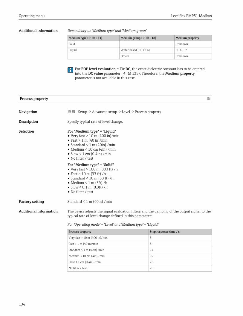
Operating menu Levelflex FMP51 Modbus
134
Additional information Dependency on "Medium type" and "Medium group"
Medium type (→ 133) Medium group (→ 118) Medium property
Solid Unknown
Liquid Water based (DC >= 4) DC 4 ... 7
Others Unknown
For EOP level evaluation = Fix DC, the exact dielectric constant has to be enteredinto the DC value parameter (→ 125). Therefore, the Medium propertyparameter is not available in this case.
Process property
Navigation Setup → Advanced setup → Level → Process property
Description Specify typical rate of level change.
Selection For "Medium type" = "Liquid"• Very fast > 10 m (400 in)/min• Fast > 1 m (40 in)/min• Standard < 1 m (40in) /min• Medium < 10 cm (4in) /min• Slow < 1 cm (0.4in) /min• No filter / test
For "Medium type" = "Solid"• Very fast > 100 m (333 ft) /h• Fast > 10 m (33 ft) /h• Standard < 10 m (33 ft) /h• Medium < 1 m (3ft) /h• Slow < 0.1 m (0.3ft) /h• No filter / test
Factory setting Standard < 1 m (40in) /min
Additional information The device adjusts the signal evaluation filters and the damping of the output signal to thetypical rate of level change defined in this parameter:
For "Operating mode" = "Level" and "Medium type" = "Liquid"
Process property Step response time / s
Very fast > 10 m (400 in)/min 5
Fast > 1 m (40 in)/min 5
Standard < 1 m (40in) /min 14
Medium < 10 cm (4in) /min 39
Slow < 1 cm (0.4in) /min 76
No filter / test < 1
Levelflex FMP51 Modbus Operating menu
135
For "Operating mode" = "Level" and "Medium type" = "Solid"
Process property Step response time / s
Very fast > 100 m (333 ft) /h 37
Fast > 10 m (33 ft) /h 37
Standard < 10 m (33 ft) /h 74
Medium < 1 m (3ft) /h 146
Slow < 0.1 m (0.3ft) /h 290
No filter / test < 1
For "Operating mode" = "Interface" or "Interface with capacitance"
Process property Step response time / s
Very fast > 10 m (400 in)/min 5
Fast > 1 m (40 in)/min 5
Standard < 1 m (40in) /min 23
Medium < 10 cm (4in) /min 47
Slow < 1 cm (0.4in) /min 81
No filter / test 2.2
Advanced process conditions
Navigation Setup → Advanced setup → Level → Advanced process conditions
Prerequisite Operating mode (→ 117) = Level
Description Specify additional process conditions (if required).
Selection • None• Oil/Water condensate• Probe near tank bottom• Build up• Foam (>5cm/0,16ft)
Factory setting None
Additional information Meaning of the options• Oil/Water condensate (only Medium type = Liquid)
Makes sure that in the case of two-phase media only the total level is detected (example:oil/condensate application).
• Probe near tank bottom (only for Medium type = Liquid)Improves the empty detection, especially if the probe is mounted close to the tankbottom.
• Build upEnables a safe empty-detection even if the end-of-probe signal has shifted due to build-up.
• Foam (>5cm/0,16ft) (only for Medium type = Liquid)Optimizes the signal evaluation in applications with foam formation.
Operating menu Levelflex FMP51 Modbus
136
Level unit
Navigation Setup → Advanced setup → Level → Level unit
Description Select level unit.
Selection SI units• %• m• mm
US units• ft• in
Factory setting %
Additional information The level unit may differ from the distance unit defined in the Distance unit parameter(→ 117):
• The unit defined in the Distance unit parameter is used for the basic calibration (Emptycalibration (→ 119) and Full calibration (→ 120)).
• The unit defined in the Level unit parameter is used to display the (unlinearized) level.
Blocking distance
Navigation Setup → Advanced setup → Level → Blocking distance
Description Specify upper blocking distance UB.
User entry 0 to 200 m
Factory setting • For coax probes: 0 mm (0 in)• For rod and rope probes up to 8 m (26 ft): 200 mm (8 in)• For rod and rope probes above 8 m (26 ft): 0.025 * Sondenlänge
For FMP51/FMP52/FMP54 with the Interface measurement application package 11) andfor FMP55:100 mm (3.9 in) for all antenna types
Additional information Signals in the upper blocking distance are only evaluated if they have been outside theblocking distance when the device was switched on and move into the blocking distancedue to a level change during operation. Signals which are already in the blocking distancewhen the device is switched on, are ignored.
This behavior is only valid if the following two conditions are met:• Expert → Sensor → Echo tracking → Evaluation mode = Short time history or Long
time history)• Expert → Sensor → Gas phase compensation → GPC mode= On, Without correction
or External correctionIf one of these conditions is not met, signals in the blocking distance will always beignored.
If required, a different behavior for signals in the blocking distance can be defined bythe Endress+Hauser service.
11) Ordering feature 540 "Application Package", option EB "Interface measurement"
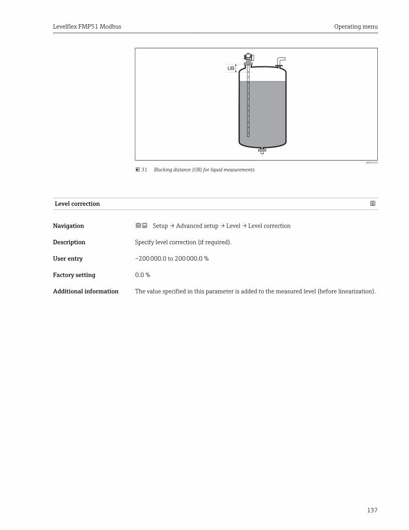
Levelflex FMP51 Modbus Operating menu
137
UB
A0013219
31 Blocking distance (UB) for liquid measurements
Level correction
Navigation Setup → Advanced setup → Level → Level correction
Description Specify level correction (if required).
User entry –200 000.0 to 200 000.0 %
Factory setting 0.0 %
Additional information The value specified in this parameter is added to the measured level (before linearization).
Operating menu Levelflex FMP51 Modbus
138
"Interface" submenu
Navigation Setup → Advanced setup → Interface
Process property
Navigation Setup → Advanced setup → Interface → Process property
Description Specify typical rate of change for the interface position.
Selection • Fast > 1 m (40 in)/min• Standard < 1 m (40in) /min• Medium < 10 cm (4in) /min• Slow < 1 cm (0.4in) /min• No filter / test
Factory setting Standard < 1 m (40in) /min
Additional information The device adjusts the signal evaluation filters and the damping of the output signal to thetypical rate of level change defined in this parameter:
Process property Step response time / s
Fast > 1 m (40 in)/min 5
Standard < 1 m (40in) /min 15
Medium < 10 cm (4in) /min 40
Slow < 1 cm (0.4in) /min 74
No filter / test 2.2
DC value lower medium
Navigation Setup → Advanced setup → Interface → DC value lower medium
Prerequisite Operating mode (→ 117) = Interface or Interface with capacitance
Description Specify the relative dielectric ocnstant εr of the lower medium.
User entry 1 to 100
Factory setting 80.0
Additional information For dielectric constants (DC values) of many media commonly used in variousindustries refer to:• the Endress+Hauser DC manual (CP01076F)• the Endress+Hauser "DC Values App" (available for Android and iOS)
The factory setting, εr = 80, is valid for water at 20 °C (68 °F).
Levelflex FMP51 Modbus Operating menu
139
Level unit
Navigation Setup → Advanced setup → Interface → Level unit
Description Select level unit.
Selection SI units• %• m• mm
US units• ft• in
Factory setting %
Additional information The level unit may differ from the distance unit defined in the Distance unit parameter(→ 117):
• The unit defined in the Distance unit parameter is used for the basic calibration (Emptycalibration (→ 119) and Full calibration (→ 120)).
• The unit defined in the Level unit parameter is used to display the (unlinearized) leveland interface position.
Blocking distance
Navigation Setup → Advanced setup → Interface → Blocking distance
Description Specify upper blocking distance UB.
User entry 0 to 200 m
Factory setting • For coax probes: 100 mm (3.9 in)• For rod and rope probes up to 8 m (26 ft): 200 mm (8 in)• For rod and rope probes above 8 m (26 ft): 0.025 * length of probe
Additional information Echoes from within the blocking distance are not taken into account in the signalevaluation. The upper blocking distance is used
• to suppress interference echoes at the top end of the probe.• to suppress the echo of the total level in the case of flooded bypasses.
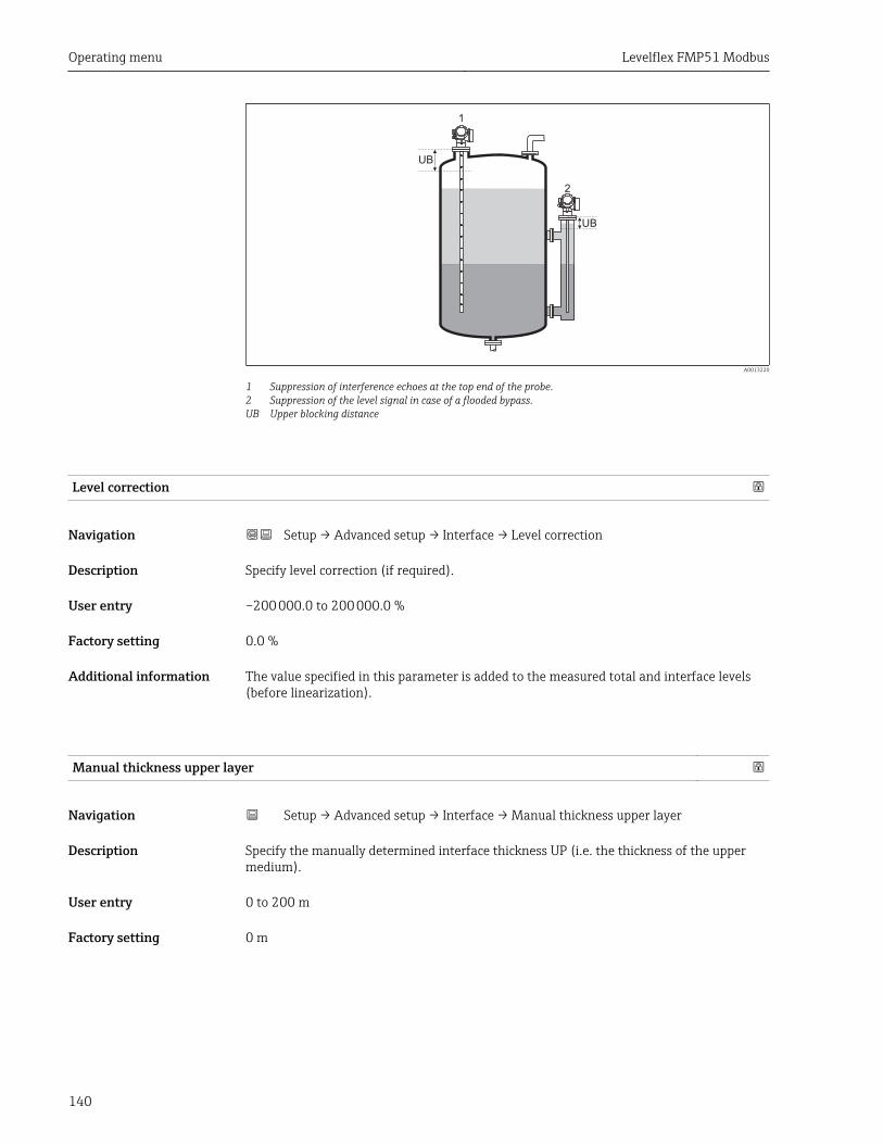
Operating menu Levelflex FMP51 Modbus
140
1
2
UB
UB
A0013220
1 Suppression of interference echoes at the top end of the probe.2 Suppression of the level signal in case of a flooded bypass.UB Upper blocking distance
Level correction
Navigation Setup → Advanced setup → Interface → Level correction
Description Specify level correction (if required).
User entry –200 000.0 to 200 000.0 %
Factory setting 0.0 %
Additional information The value specified in this parameter is added to the measured total and interface levels(before linearization).
Manual thickness upper layer
Navigation Setup → Advanced setup → Interface → Manual thickness upper layer
Description Specify the manually determined interface thickness UP (i.e. the thickness of the uppermedium).
User entry 0 to 200 m
Factory setting 0 m
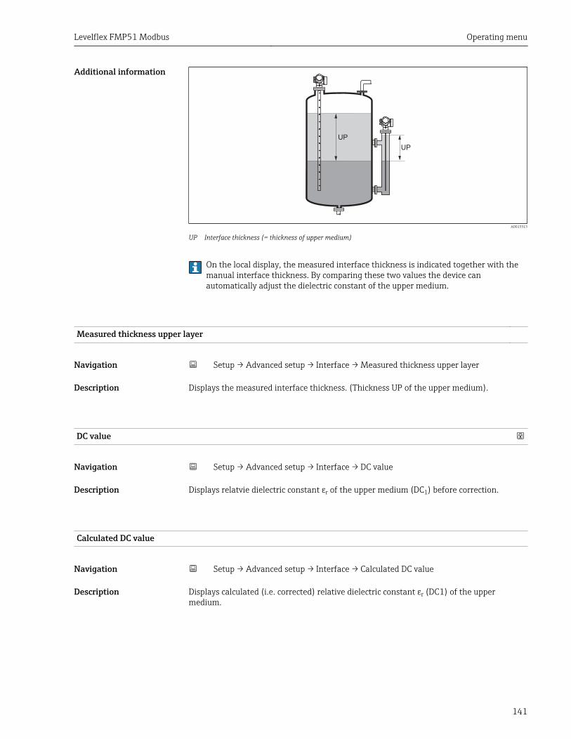
Levelflex FMP51 Modbus Operating menu
141
Additional information
UP
UP
A0013313
UP Interface thickness (= thickness of upper medium)
On the local display, the measured interface thickness is indicated together with themanual interface thickness. By comparing these two values the device canautomatically adjust the dielectric constant of the upper medium.
Measured thickness upper layer
Navigation Setup → Advanced setup → Interface → Measured thickness upper layer
Description Displays the measured interface thickness. (Thickness UP of the upper medium).
DC value
Navigation Setup → Advanced setup → Interface → DC value
Description Displays relatvie dielectric constant εr of the upper medium (DC1) before correction.
Calculated DC value
Navigation Setup → Advanced setup → Interface → Calculated DC value
Description Displays calculated (i.e. corrected) relative dielectric constant εr (DC1) of the uppermedium.
Operating menu Levelflex FMP51 Modbus
142
Use calculated DC value
Navigation Setup → Advanced setup → Interface → Use calculated DC value
Description Specify whether the calculated dielectric constant is to be used.
Selection • Save and exit• Cancel and exit
Factory setting Cancel and exit
Additional information Meaning of the options• Save and exit
The calculated constant is assumed to be the correct one.• Cancel and exit
The calculated dielectric constant is rejected; the previous dielectric constant remainsactive.
On the local display, the Calculated DC value parameter (→ 141) is displayedtogether with this parameter.
Levelflex FMP51 Modbus Operating menu
143
"Automatic DC calculation" wizard
The Automatic DC calculation wizard is only available when operating via the localdisplay. When operating via an operating tool, all parameters concerning theautomatic DC calculation are located directly in the Interface submenu (→ 138)
In the Automatic DC calculation wizard two parameters are displayed simultaneouslyon the display module at any one time. The upper parameter can be edited, whereasthe lower parameter is displayed for reference purposes only.
Navigation Setup → Advanced setup → Interface → Automatic DCcalculation
Manual thickness upper layer
Navigation Setup → Advanced setup → Interface → Automatic DC calculation → Manualthickness upper layer
Description → 140
DC value
Navigation Setup → Advanced setup → Interface → Automatic DC calculation → DC value
Description → 141
Use calculated DC value
Navigation Setup → Advanced setup → Interface → Automatic DC calculation → Use calculatedDC value
Description → 142
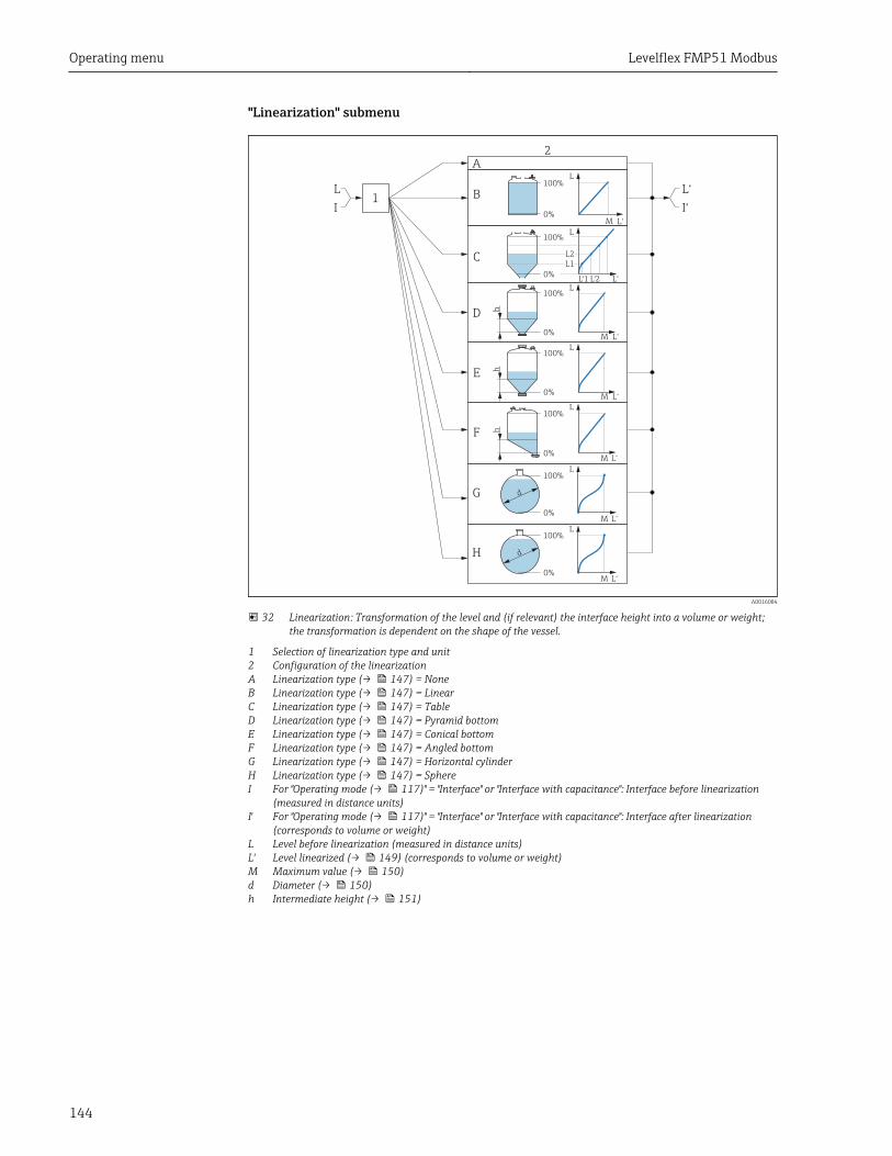
Operating menu Levelflex FMP51 Modbus
144
"Linearization" submenu
0%
100%L
L
L
L
L
L
L
L‘1 L‘2
L‘
L‘
L‘
L‘
L‘
L‘
L‘
M
M
M
M
M
hh
h
M
0%
100%
100%
100%
0%
0%
100%
0%
0%
0%
100%
100%
B
A
C
D
E
F
G
H
2
1L
I
L‘
I‘
d
d
L2
L1
A0016084
32 Linearization: Transformation of the level and (if relevant) the interface height into a volume or weight;the transformation is dependent on the shape of the vessel.
1 Selection of linearization type and unit2 Configuration of the linearizationA Linearization type (→ 147) = NoneB Linearization type (→ 147) = LinearC Linearization type (→ 147) = TableD Linearization type (→ 147) = Pyramid bottomE Linearization type (→ 147) = Conical bottomF Linearization type (→ 147) = Angled bottomG Linearization type (→ 147) = Horizontal cylinderH Linearization type (→ 147) = SphereI For "Operating mode (→ 117)" = "Interface" or "Interface with capacitance": Interface before linearization
(measured in distance units)I' For "Operating mode (→ 117)" = "Interface" or "Interface with capacitance": Interface after linearization
(corresponds to volume or weight)L Level before linearization (measured in distance units)L' Level linearized (→ 149) (corresponds to volume or weight)M Maximum value (→ 150)d Diameter (→ 150)h Intermediate height (→ 151)
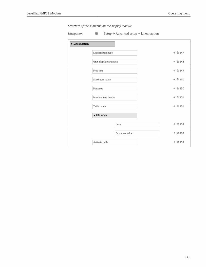
Levelflex FMP51 Modbus Operating menu
145
Structure of the submenu on the display module
Navigation Setup → Advanced setup → Linearization
‣ Linearization
Linearization type → 147
Unit after linearization → 148
Free text → 149
Maximum value → 150
Diameter → 150
Intermediate height → 151
Table mode → 151
‣ Edit table
Level → 153
Customer value → 153
Activate table → 153
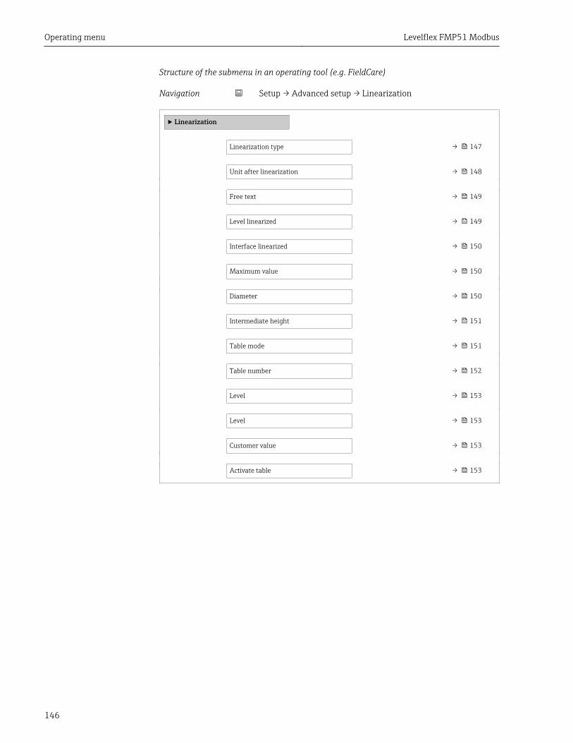
Operating menu Levelflex FMP51 Modbus
146
Structure of the submenu in an operating tool (e.g. FieldCare)
Navigation Setup → Advanced setup → Linearization
‣ Linearization
Linearization type → 147
Unit after linearization → 148
Free text → 149
Level linearized → 149
Interface linearized → 150
Maximum value → 150
Diameter → 150
Intermediate height → 151
Table mode → 151
Table number → 152
Level → 153
Level → 153
Customer value → 153
Activate table → 153
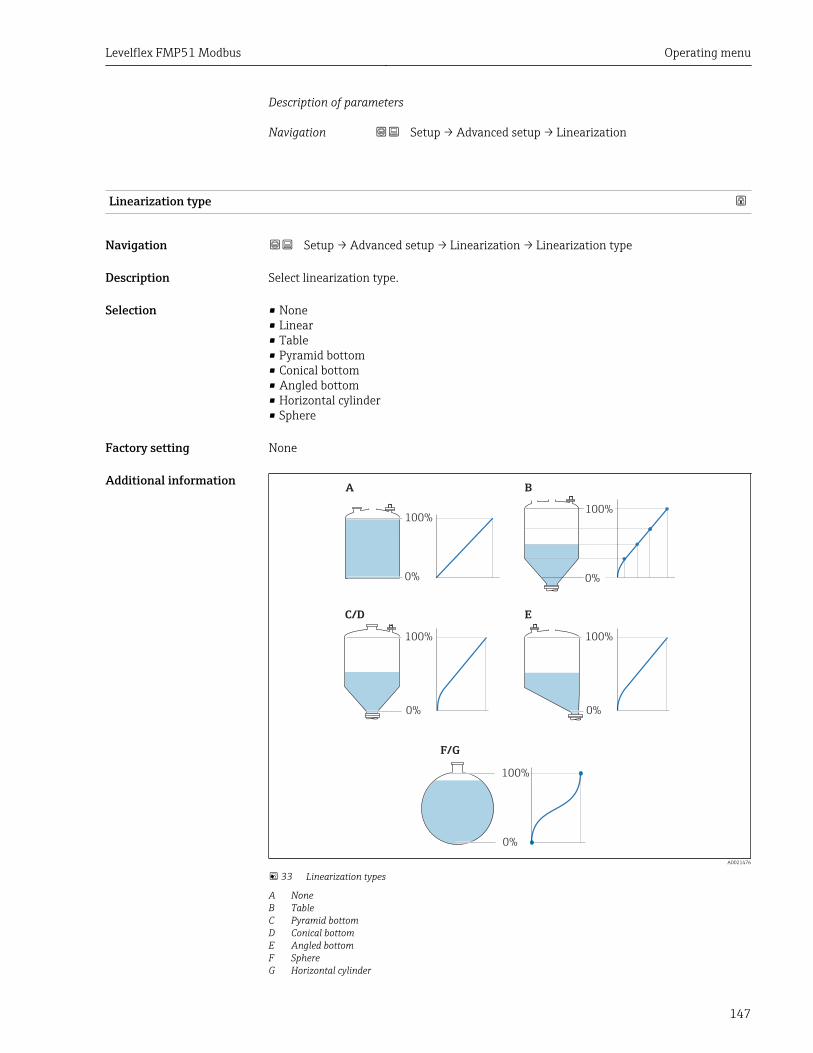
Levelflex FMP51 Modbus Operating menu
147
Description of parameters
Navigation Setup → Advanced setup → Linearization
Linearization type
Navigation Setup → Advanced setup → Linearization → Linearization type
Description Select linearization type.
Selection • None• Linear• Table• Pyramid bottom• Conical bottom• Angled bottom• Horizontal cylinder• Sphere
Factory setting None
Additional information
0%
100%
0%
100%
100%
0%
100%
0%
0%
100%
A B
C/D E
F/G
A0021476
33 Linearization types
A NoneB TableC Pyramid bottomD Conical bottomE Angled bottomF SphereG Horizontal cylinder

Operating menu Levelflex FMP51 Modbus
148
Meaning of the options• None
The level is transmitted in the level unit without linearization.• Linear
The output value (volume/weight) is directly proportional to the level L. This is valid, forexample, for vertical cylinders. The following additional parameters have to be specified:– Unit after linearization (→ 148)– Maximum value (→ 150): Maximum volume or weight
• TableThe relationship between the measured level L and the output value (volume/weight) isgiven by a linearization table consisting of up to 32 pairs of values "level - volume" or"level - weight", respectively. The following additional parameters have to be specified:– Unit after linearization (→ 148)– Table mode (→ 151)– For each table point: Level (→ 153)– For each table point: Customer value (→ 153)– Activate table (→ 153)
• Pyramid bottomThe output value corresponds to the volume or weight in a silo with pyramid bottom.The following additional parameters have to be specified:– Unit after linearization (→ 148)– Maximum value (→ 150): Maximum volume or weight– Intermediate height (→ 151): The height of the pyramid
• Conical bottomThe output value corresponds to the volume or weight in a tank with conical bottom. Thefollowing additional parameters have to be specified:– Unit after linearization (→ 148)– Maximum value (→ 150): Maximum volume or weight– Intermediate height (→ 151): The height of the conical part of the tank
• Angled bottomThe output value corresponds to the volume or weight in a silo with an angled bottom.The following additional parameters have to be specified:– Unit after linearization (→ 148)– Maximum value (→ 150): Maximum volume or weight– Intermediate height (→ 151): Height of the angled bottom
• Horizontal cylinderThe output value corresponds to the volume or weight in a horizontal cylinder. Thefollowing additional parameters have to be specified:– Unit after linearization (→ 148)– Maximum value (→ 150): Maximum volume or weight– Diameter (→ 150)
• SphereThe output value corresponds to the volume or weight in a spherical tank. The followingadditional parameters have to be specified:– Unit after linearization (→ 148)– Maximum value (→ 150): Maximum volume or weight– Diameter (→ 150)
Unit after linearization
Navigation Setup → Advanced setup → Linearization → Unit after linearization
Prerequisite Linearization type (→ 147) ≠ None
Description Select unit of the lineaized value.
Levelflex FMP51 Modbus Operating menu
149
Selection SI units• STon• t• kg• cm³• dm³• m³• hl• l• %• mm• m
US units• lb• UsGal• ft³• ft• in
Imperial unitsimpGal
Custom-specific unitsFree text
Factory setting %
Additional information The selected unit is only used to be indicated on the display. The measured value is nottransformed according to the selected unit.
It is also possible to configure a distance-to-distance linearization, i.e. atransformation from the level unit to a different distance unit. To do so, select theLinear linearization mode. In order to define the new level unit, select the Free textoption in the Unit after linearization parameter and enter the required unit into theFree text parameter (→ 149).
Free text
Navigation Setup → Advanced setup → Linearization → Free text
Prerequisite Unit after linearization (→ 148) = Free text
Description Enter unit symbol.
User entry Up to 32 alphanumerical characters (letters, numbers, special characters)
Factory setting Free text
Level linearized
Navigation Setup → Advanced setup → Linearization → Level linearized
Description Displays linearized level.
Additional information • The unit is defined by the Unit after linearization parameter → 148.• For interface measurements, this parameter always refers to the total level.
Operating menu Levelflex FMP51 Modbus
150
Interface linearized
Navigation Setup → Advanced setup → Linearization → Interface linearized
Prerequisite Operating mode (→ 117) = Interface or Interface with capacitance
Description Displays the linearized interface height.
Additional information The unit is defined in the Unit after linearization parameter → 148.
Maximum value
Navigation Setup → Advanced setup → Linearization → Maximum value
Prerequisite Linearization type (→ 147) has one of the following values:• Linear• Pyramid bottom• Conical bottom• Angled bottom• Horizontal cylinder• Sphere
Description Linearized value corresponding to a level of 100%.
User entry –50 000.0 to 50 000.0 %
Factory setting 100.0 %
Diameter
Navigation Setup → Advanced setup → Linearization → Diameter
Prerequisite Linearization type (→ 147) has one of the following values:• Horizontal cylinder• Sphere
Description Diameter of the cylindrical or spherical tank.
User entry 0 to 9 999.999 m
Factory setting 2 m
Additional information The unit is defined in the Distance unit parameter (→ 117).
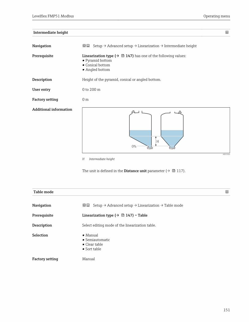
Levelflex FMP51 Modbus Operating menu
151
Intermediate height
Navigation Setup → Advanced setup → Linearization → Intermediate height
Prerequisite Linearization type (→ 147) has one of the following values:• Pyramid bottom• Conical bottom• Angled bottom
Description Height of the pyramid, conical or angled bottom.
User entry 0 to 200 m
Factory setting 0 m
Additional information
0%
H
A0013264
H Intermediate height
The unit is defined in the Distance unit parameter (→ 117).
Table mode
Navigation Setup → Advanced setup → Linearization → Table mode
Prerequisite Linearization type (→ 147) = Table
Description Select editing mode of the linearization table.
Selection • Manual• Semiautomatic• Clear table• Sort table
Factory setting Manual
Operating menu Levelflex FMP51 Modbus
152
Additional information Meaning of the options• Manual
The level and the associated linearized value are entered manually for each linearizationpoint.
• SemiautomaticThe level is measured by the device for each linearization point. The associatedlinearized value is entered manually.
• Clear tableDeletes the existing linearization table.
• Sort tableRearranges the linerization points into an ascending order.
Conditions the linearization table must meet:• The table may consist of up to 32 pairs of values "Level - Linearized Value".• The table must be monotonic (monotonically increasing or decreasing).• The first linearization point must refer to the minimum level.• The last linearization point must refer to the maximum level.
Before entering a linearization table, the values for Empty calibration (→ 119)and Full calibration (→ 120) must be set correctly.
If values of the table need to be changed after the full or empty calibration have beenchanged, a correct evaluation is only ensured if the existing table is deleted and thecomplete table is entered again. To do so delete the existing table (Table mode(→ 151) = Clear table). Then enter a new table.
How to enter the table• Via FieldCare
The table points can be entered via the Table number (→ 152), Level (→ 153)and Customer value (→ 153) parameters. As an alternative, the graphic table editormay be used: Device Operation → Device Functions → Additional Functions →Linearization (Online/Offline)
• Via local displaySelect the Edit table submenu to call up the graphic table editor. The table is displayedand can be edited line by line.
The factory setting for the level unit is "%". If you want to enter the linearization tablein physical units, you must select the appropriate unit in the Level unit parameter(→ 136) beforehand.
Table number
Navigation Setup → Advanced setup → Linearization → Table number
Prerequisite Linearization type (→ 147) = Table
Description Select table point you are going to enter or change.
User entry 1 to 32
Factory setting 1
Levelflex FMP51 Modbus Operating menu
153
Level (Manual)
Navigation Setup → Advanced setup → Linearization → Level
Prerequisite • Linearization type (→ 147) = Table• Table mode (→ 151) = Manual
Description Enter level value of the table point (value before linearization).
User entry Signed floating-point number
Factory setting 0 %
Level (Semiautomatic)
Navigation Setup → Advanced setup → Linearization → Level
Prerequisite • Linearization type (→ 147) = Table• Table mode (→ 151) = Semiautomatic
Description Displays measured level (value before linearization). This value is transmitted to the table.
Customer value
Navigation Setup → Advanced setup → Linearization → Customer value
Prerequisite Linearization type (→ 147) = Table
Description Enter linearized value for the table point.
User entry Signed floating-point number
Factory setting 0 %
Activate table
Navigation Setup → Advanced setup → Linearization → Activate table
Prerequisite Linearization type (→ 147) = Table
Description Activate (enable) or deactivate (disable) the linearization table.
Selection • Disable• Enable

Operating menu Levelflex FMP51 Modbus
154
Factory setting Disable
Additional information Meaning of the options• Disable
The measured level is not linearized.If Linearization type (→ 147) = Table at the same time, the device issues errormessage F435.
• EnableThe measured level is linearized according to the table.
When editing the table, the Activate table parameter is automatically reset toDisable and must be reset to Enable after the table has been entered.
Levelflex FMP51 Modbus Operating menu
155
"Safety settings" submenu
Navigation Setup → Advanced setup → Safety settings
Output echo lost
Navigation Setup → Advanced setup → Safety settings → Output echo lost
Description Output signal in case of a lost echo.
Selection • Last valid value• Ramp at echo lost• Value echo lost• Alarm
Factory setting Last valid value
Additional information Meaning of the options• Last valid value
The last valid value is kept in the case of a lost echo.• Ramp at echo lost 12)
In the case of a lost echo the output value is continously shifted towards 0% or 100%.The slope of the ramp is defined in the Ramp at echo lost parameter (→ 156).
• Value echo lost 12)
In the case of a lost echo the output assumes the value defined in the Value echo lostparameter (→ 155).
• AlarmIn the case of a lost echo the device generates an alarm; see the Failure mode parameter
Value echo lost
Navigation Setup → Advanced setup → Safety settings → Value echo lost
Prerequisite Output echo lost (→ 155) = Value echo lost
Description Output value in case of a lost echo
User entry 0 to 200 000.0 %
Factory setting 0.0 %
Additional information Use the unit which has been defined for the measured value output:• without linearization: Level unit (→ 136)• with linearization: Unit after linearization (→ 148)
12) Only visible if '"Linearization type (→ 147)" = "None"

Operating menu Levelflex FMP51 Modbus
156
Ramp at echo lost
Navigation Setup → Advanced setup → Safety settings → Ramp at echo lost
Prerequisite Output echo lost (→ 155) = Ramp at echo lost
Description Slope of the ramp in the case of a lost echo
User entry Signed floating-point number
Factory setting 0.0 %/min
Additional information
t
min
0%
100%
A
B
C
A0013269
A Delay time echo lostB Ramp at echo lost (→ 156) (positive value)C Ramp at echo lost (→ 156) (negative value)
• The unit for the slope of the ramp is "percentage of the measuring range per minute" (%/min).
• For a negative slope of the ramp: The measured value is continuously decreased until itreaches 0%.
• For a positive slope of the ramp: The measured value is continuosly increased until itreaches 100%.
Blocking distance
Navigation Setup → Advanced setup → Safety settings → Blocking distance
Description Specify upper blocking distance UB.
User entry 0 to 200 m
Factory setting • For coax probes: 0 mm (0 in)• For rod and rope probes up to 8 m (26 ft): 200 mm (8 in)• For rod and rope probes above 8 m (26 ft): 0.025 * Sondenlänge
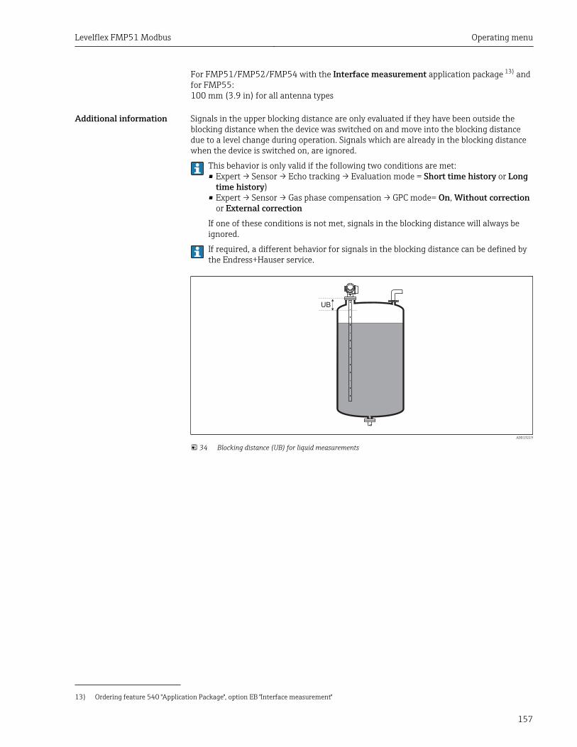
Levelflex FMP51 Modbus Operating menu
157
For FMP51/FMP52/FMP54 with the Interface measurement application package 13) andfor FMP55:100 mm (3.9 in) for all antenna types
Additional information Signals in the upper blocking distance are only evaluated if they have been outside theblocking distance when the device was switched on and move into the blocking distancedue to a level change during operation. Signals which are already in the blocking distancewhen the device is switched on, are ignored.
This behavior is only valid if the following two conditions are met:• Expert → Sensor → Echo tracking → Evaluation mode = Short time history or Long
time history)• Expert → Sensor → Gas phase compensation → GPC mode= On, Without correction
or External correctionIf one of these conditions is not met, signals in the blocking distance will always beignored.
If required, a different behavior for signals in the blocking distance can be defined bythe Endress+Hauser service.
UB
A0013219
34 Blocking distance (UB) for liquid measurements
13) Ordering feature 540 "Application Package", option EB "Interface measurement"
Operating menu Levelflex FMP51 Modbus
158
"Probe settings" submenuThe Probe settings submenu helps to ensure that the end of probe signal within theenvelope curve is correctly assigned by the evaluation algorithm. The assignment is correctif the length of probe indicated by the device matches the acutal lenght of the probe. Theautomatic probe length correction can only be performed if the probe is installed in thevessel and is completely uncovered (no medium). For partially filled vessels and if theprobe length is known, select Confirm probe length (→ 159) = Manual input in orderto enter the value manually.
If a mapping (interference echo suppression) has been recorded after shortening theprobe, it is no longer possible to perform an automatic probe length correction. In thiscase there are two options:• Delete the map using the Record map parameter (→ 129) before performing the
automatic probe length correction. After the probe length correction, a new mapcan be recorded using the Record map parameter (→ 129).
• Alternative: Select Confirm probe length (→ 159) = Manual input and enterthe probe length manually into the Present probe length parameter → 158.
An automatic probe length correction is only possible after the correct option hasbeen selected in the Probe grounded parameter (→ 158).
Navigation Setup → Advanced setup → Probe settings
Probe grounded
Navigation Setup → Advanced setup → Probe settings → Probe grounded
Prerequisite Operating mode (→ 117) = Level
Description Specify whether the probe is grounded.
Selection • No• Yes
Factory setting No
Present probe length
Navigation Setup → Advanced setup → Probe settings → Present probe length
Description • In most cases:Displays the length of the probe according to the currently measured end-of-probesignal.
• For Confirm probe length (→ 159) = Manual input:Enter actual length of probe.
User entry 0 to 200 m
Factory setting 4 m
Levelflex FMP51 Modbus Operating menu
159
Confirm probe length
Navigation Setup → Advanced setup → Probe settings → Confirm probe length
Description Select, whether the value displayed in the Present probe length parameter → 158matches the actual length of the probe. Based on this input, the device performs a probelength correction.
Selection • Probe length OK• Probe length too small• Probe length too big• Probe covered• Manual input• Probe length unknown
Factory setting Probe length OK
Additional information Meaning of the options• Probe length OK
To be selected if the indicated length is correct. An adjustment is not required. Thedevice quits the sequence.
• Probe length too smallTo be selected if the displayed length is smaller than the actual length of the probe. Adifferent end of probe signal is allocated and the newly calculated length is displayed inthe Present probe length parameter → 158. This procedure has to be repeated untilthe displayed value matches the actual length of the probe.
• Probe length too bigTo be selected if the displayed length is bigger than the actual length of the probe. Adifferent end of probe signal is allocated and the newly calculated length is indicated inthe Present probe length parameter → 158. This procedure has to be repeated untilthe displayed value matches the actual length of the probe.
• Probe coveredTo be selected if the probe is (partially or completely) covered. A probe length correctionis impossible in this case. The device quits the sequence.
• Manual inputTo be selected if no automatic probe length correction is to be performed. Instead, theactual length of the probe must be entered manually into the Present probe lengthparameter → 158 14).
• Probe length unknownTo be selected if the acutal length of the probe is unknown. A probe length correction isimpossible in this case and the device quits the sequence..
14) When operated via FieldCare, the Manual input option needs not to be selected explicitly. In FieldCare the length of the probe can always beedited.
Operating menu Levelflex FMP51 Modbus
160
"Probe length correction" wizard
The Probe length correction wizard is only available when operating via the localdisplay. When operating via an operating tool, all parameters concerning the probelength correction are located directly in the Probe settings submenu (→ 158).
Navigation Setup → Advanced setup → Probe settings → Probe lengthcorrection
Confirm probe length
Navigation Setup → Advanced setup → Probe settings → Probe length correction → Confirmprobe length
Description → 159
Present probe length
Navigation Setup → Advanced setup → Probe settings → Probe length correction → Presentprobe length
Description → 158
Levelflex FMP51 Modbus Operating menu
161
"Switch output" submenuThe Switch output submenu (→ 161) is only visible for devices with switchoutput. 15)
Navigation Setup → Advanced setup → Switch output
Switch output function
Navigation Setup → Advanced setup → Switch output → Switch output function
Description Defines the function of the switch output. 'Off' The switch output is always open (non-conductive) 'On' The switch output is always closed (conductive). 'Diagnostic behavior' Theswitch output is normally closed and is only opened if a diagnostic event is present. 'Limit'The switch output is normally closed and is only opened if a measured variable exceeds adefined limit. 'Digital output' The switch output is controlled by one of the digital outputblocks of the device.
Selection • Off• On• Diagnostic behavior• Limit• Digital Output
Factory setting Off
Additional information Meaning of the options• Off
The output is always open (non-conductive).• On
The output is always closed (conductive).• Diagnostic behavior
The output is normally closed and is only opened if a diagnostic event is present. TheAssign diagnostic behavior parameter (→ 162) determines for which type of eventthe output is opened.
• LimitThe output is normally closed and is only opened if a measured variable exceeds or fallsbelow a defined limit. The limit values are defined by the following parameters:– Assign limit (→ 162)– Switch-on value (→ 163)– Switch-off value (→ 164)
• Digital OutputThe switching state of the output tracks the output value of a DI function block. Thefunction block is selected in the Assign status parameter (→ 162).
The Off and On options can be used to simulate the switch output.
15) Ordering feature 020 "Power supply; Output", option B, E or G
Operating menu Levelflex FMP51 Modbus
162
Assign status
Navigation Setup → Advanced setup → Switch output → Assign status
Prerequisite Switch output function (→ 161) = Digital Output
Selection • Off• Digital output AD 1• Digital output AD 2
Factory setting Off
Additional information The Digital output AD 1 and Digital output AD 2 options refer to the AdvancedDiagnostic Blocks. A switch signal generated in these blocks can be transmitted via theswitch output.
Assign limit
Navigation Setup → Advanced setup → Switch output → Assign limit
Prerequisite Switch output function (→ 161) = Limit
Selection • Off• Level linearized• Distance• Interface linearized *
• Interface distance *
• Thickness upper layer *
• Terminal voltage• Electronic temperature• Measured capacitance *
• Relative echo amplitude• Relative interface amplitude *
• Absolute echo amplitude• Absolute interface amplitude *
Factory setting Off
Assign diagnostic behavior
Navigation Setup → Advanced setup → Switch output → Assign diagnostic behavior
Prerequisite Switch output function (→ 161) = Diagnostic behavior
Description Defines to which behavior of diagnostic events the switch output reacts.
* Visibility depends on order options or device settings
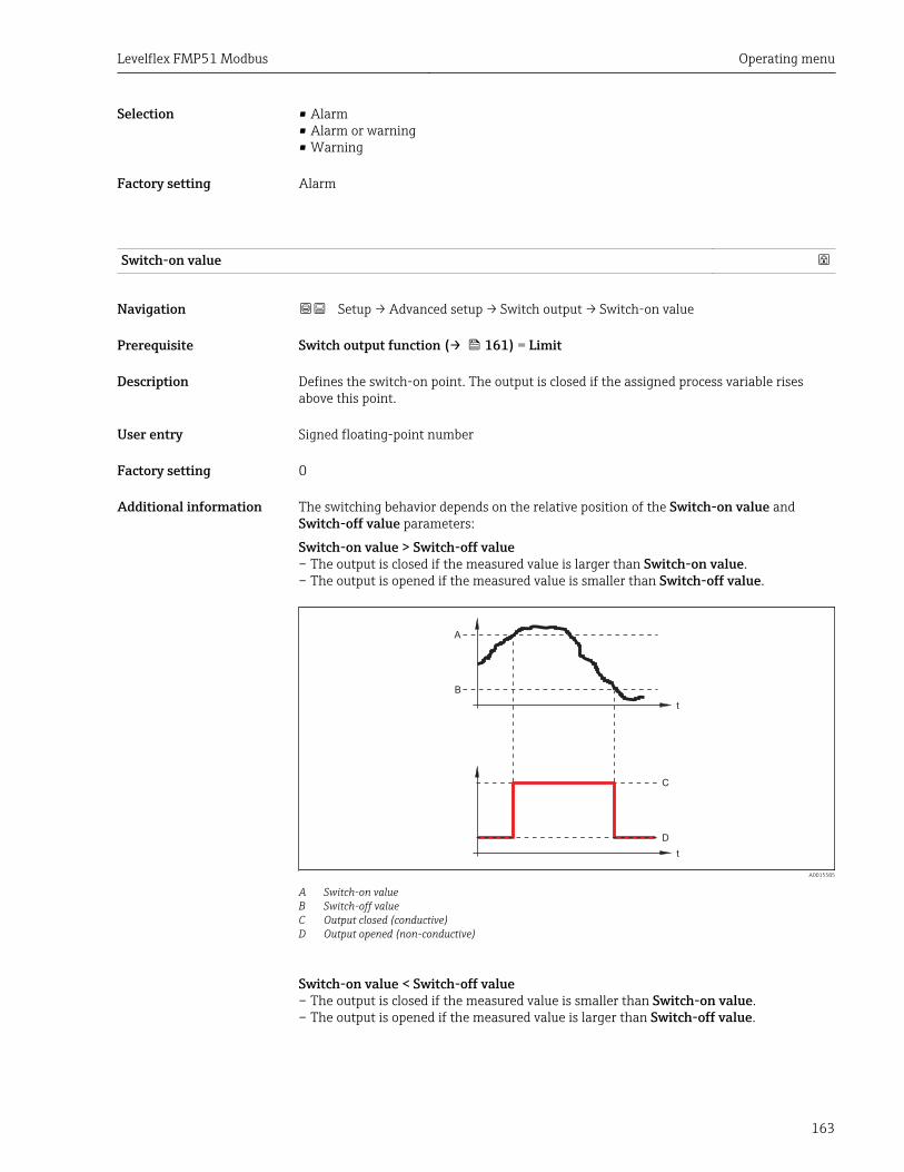
Levelflex FMP51 Modbus Operating menu
163
Selection • Alarm• Alarm or warning• Warning
Factory setting Alarm
Switch-on value
Navigation Setup → Advanced setup → Switch output → Switch-on value
Prerequisite Switch output function (→ 161) = Limit
Description Defines the switch-on point. The output is closed if the assigned process variable risesabove this point.
User entry Signed floating-point number
Factory setting 0
Additional information The switching behavior depends on the relative position of the Switch-on value andSwitch-off value parameters:
Switch-on value > Switch-off value– The output is closed if the measured value is larger than Switch-on value.– The output is opened if the measured value is smaller than Switch-off value.
t
t
A
B
C
D
A0015585
A Switch-on valueB Switch-off valueC Output closed (conductive)D Output opened (non-conductive)
Switch-on value < Switch-off value– The output is closed if the measured value is smaller than Switch-on value.– The output is opened if the measured value is larger than Switch-off value.
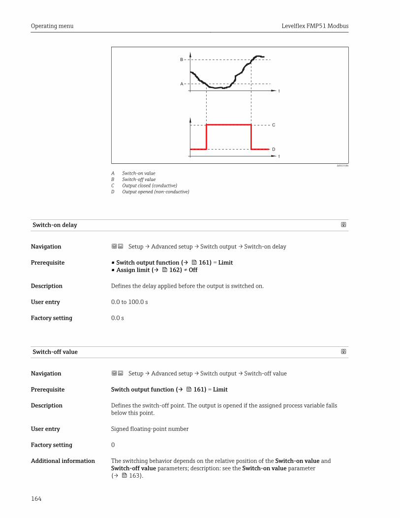
Operating menu Levelflex FMP51 Modbus
164
t
t
B
A
C
D
A0015586
A Switch-on valueB Switch-off valueC Output closed (conductive)D Output opened (non-conductive)
Switch-on delay
Navigation Setup → Advanced setup → Switch output → Switch-on delay
Prerequisite • Switch output function (→ 161) = Limit• Assign limit (→ 162) ≠ Off
Description Defines the delay applied before the output is switched on.
User entry 0.0 to 100.0 s
Factory setting 0.0 s
Switch-off value
Navigation Setup → Advanced setup → Switch output → Switch-off value
Prerequisite Switch output function (→ 161) = Limit
Description Defines the switch-off point. The output is opened if the assigned process variable fallsbelow this point.
User entry Signed floating-point number
Factory setting 0
Additional information The switching behavior depends on the relative position of the Switch-on value andSwitch-off value parameters; description: see the Switch-on value parameter(→ 163).
Levelflex FMP51 Modbus Operating menu
165
Switch-off delay
Navigation Setup → Advanced setup → Switch output → Switch-off delay
Prerequisite • Switch output function (→ 161) = Limit• Assign limit (→ 162) ≠ Off
Description Defines the delay applied before the output is switched off.
User entry 0.0 to 100.0 s
Factory setting 0.0 s
Failure mode
Navigation Setup → Advanced setup → Switch output → Failure mode
Prerequisite Switch output function (→ 161) = Limit or Digital Output
Description Defines the state of the switch output in case of an error.
Selection • Actual status• Open• Closed
Factory setting Open
Additional information
Switch status
Navigation Setup → Advanced setup → Switch output → Switch status
Description Current status of the switch output.
Invert output signal
Navigation Setup → Advanced setup → Switch output → Invert output signal
Description 'No' The switch output behaves as per its parameter setting. 'Yes' The switching behavior isinverted as compared to its parameter setting.
Selection • No• Yes

Operating menu Levelflex FMP51 Modbus
166
Factory setting No
Additional information Meaning of the options• No
The behavior of the switch output is as described above.• Yes
The states Open and Closed are inverted as compared to the description above.
Levelflex FMP51 Modbus Operating menu
167
"Display" submenuThe Display submenu is only visible if a display module is connected to the device.
Navigation Setup → Advanced setup → Display
Language
Navigation Setup → Advanced setup → Display → Language
Description Set display language.
Selection • English• Deutsch *
• Français *
• Español *• Italiano *
• Nederlands *
• Portuguesa *
• Polski *• русский язык (Russian) *
• Svenska *
• Türkçe *
• 中文 (Chinese) *
• 日本語 (Japanese) *
• 한국어 (Korean) *
• Bahasa Indonesia *
• tiếng Việt (Vietnamese) *
• čeština (Czech) *
Factory setting The language selected in feature 500 of the product structure.If no language has been selected: English
Additional information
Format display
Navigation Setup → Advanced setup → Display → Format display
Description Select how measured values are shown on the display.
Selection • 1 value, max. size• 1 bargraph + 1 value• 2 values• 1 value large + 2 values• 4 values
Factory setting 1 value, max. size
* Visibility depends on order options or device settings
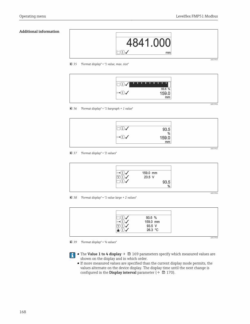
Operating menu Levelflex FMP51 Modbus
168
Additional information
4841.000mm1 Â
A0019963
35 "Format display" = "1 value, max. size"
93.5 %
159.0mm
1
1
Â
Â
A0019964
36 "Format display" = "1 bargraph + 1 value"
93.5%
159.0mm
1
1
Â
Â
A0019965
37 "Format display" = "2 values"
93.5%
159.0 mm
23.5 V
1 Â
1
1V
ÂÂ
A0019966
38 "Format display" = "1 value large + 2 values"
93.5 %159.0 mm
93.5 V26.3 °C
1 Â1
1
1
V
Â
ÂÂ
A0019968
39 "Format display" = "4 values"
• The Value 1 to 4 display → 169 parameters specify which measured values areshown on the display and in which order.
• If more measured values are specified than the current display mode permits, thevalues alternate on the device display. The display time until the next change isconfigured in the Display interval parameter (→ 170).
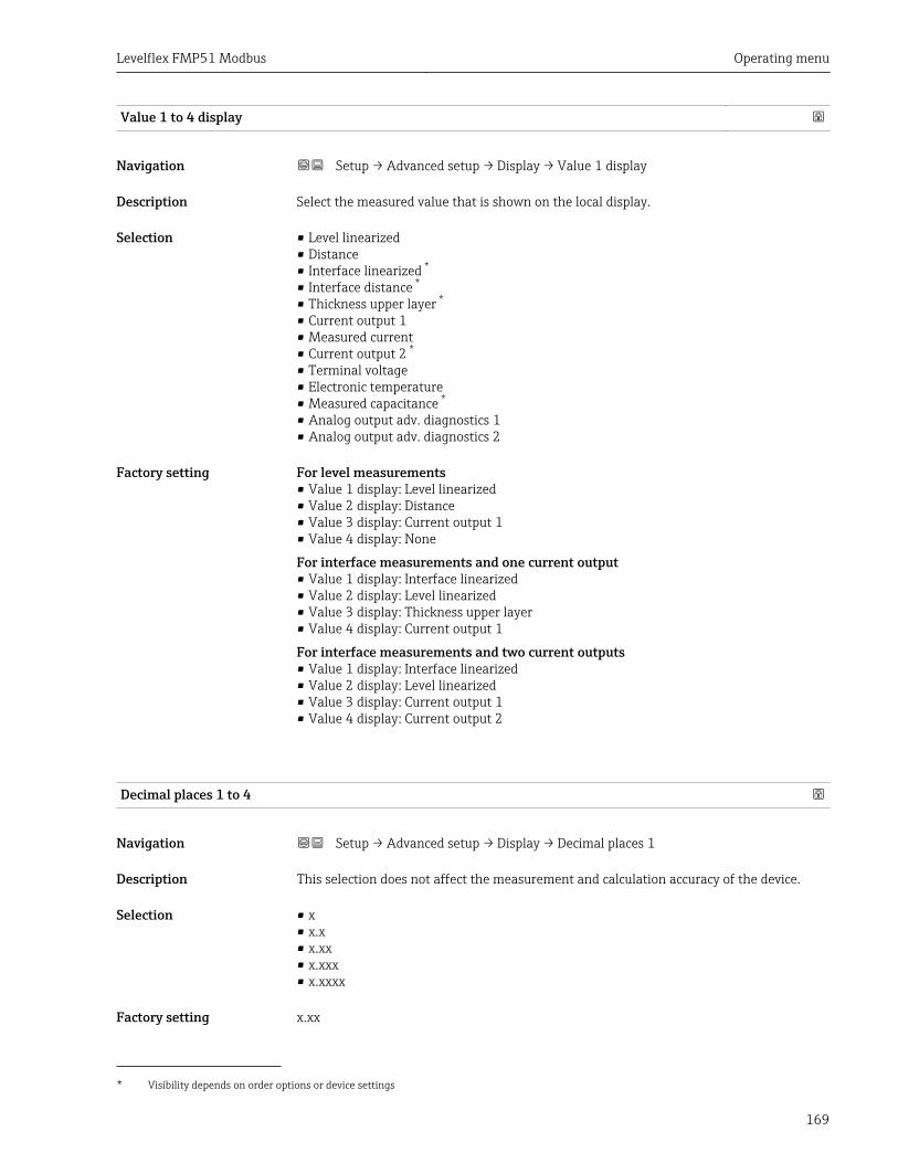
Levelflex FMP51 Modbus Operating menu
169
Value 1 to 4 display
Navigation Setup → Advanced setup → Display → Value 1 display
Description Select the measured value that is shown on the local display.
Selection • Level linearized• Distance• Interface linearized *
• Interface distance *
• Thickness upper layer *
• Current output 1• Measured current• Current output 2 *
• Terminal voltage• Electronic temperature• Measured capacitance *
• Analog output adv. diagnostics 1• Analog output adv. diagnostics 2
Factory setting For level measurements• Value 1 display: Level linearized• Value 2 display: Distance• Value 3 display: Current output 1• Value 4 display: None
For interface measurements and one current output• Value 1 display: Interface linearized• Value 2 display: Level linearized• Value 3 display: Thickness upper layer• Value 4 display: Current output 1
For interface measurements and two current outputs• Value 1 display: Interface linearized• Value 2 display: Level linearized• Value 3 display: Current output 1• Value 4 display: Current output 2
Decimal places 1 to 4
Navigation Setup → Advanced setup → Display → Decimal places 1
Description This selection does not affect the measurement and calculation accuracy of the device.
Selection • x• x.x• x.xx• x.xxx• x.xxxx
Factory setting x.xx
* Visibility depends on order options or device settings
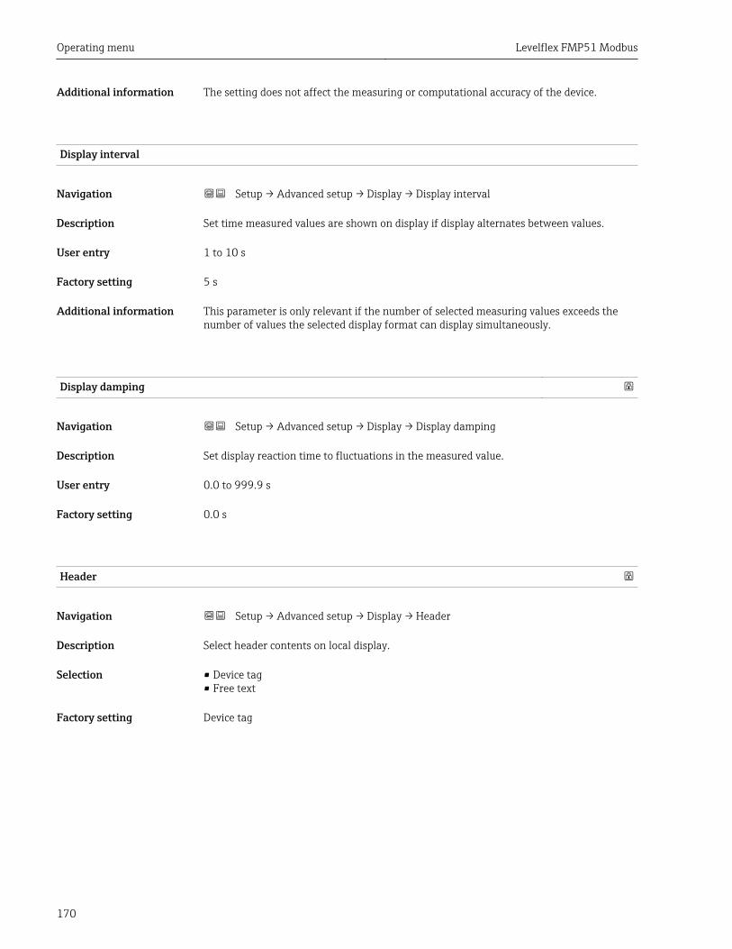
Operating menu Levelflex FMP51 Modbus
170
Additional information The setting does not affect the measuring or computational accuracy of the device.
Display interval
Navigation Setup → Advanced setup → Display → Display interval
Description Set time measured values are shown on display if display alternates between values.
User entry 1 to 10 s
Factory setting 5 s
Additional information This parameter is only relevant if the number of selected measuring values exceeds thenumber of values the selected display format can display simultaneously.
Display damping
Navigation Setup → Advanced setup → Display → Display damping
Description Set display reaction time to fluctuations in the measured value.
User entry 0.0 to 999.9 s
Factory setting 0.0 s
Header
Navigation Setup → Advanced setup → Display → Header
Description Select header contents on local display.
Selection • Device tag• Free text
Factory setting Device tag
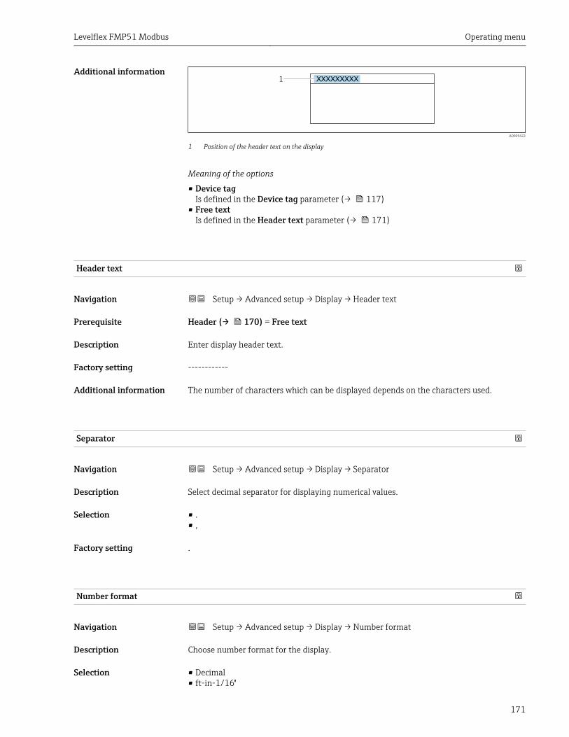
Levelflex FMP51 Modbus Operating menu
171
Additional information1 XXXXXXXXX
A0029422
1 Position of the header text on the display
Meaning of the options
• Device tagIs defined in the Device tag parameter (→ 117)
• Free textIs defined in the Header text parameter (→ 171)
Header text
Navigation Setup → Advanced setup → Display → Header text
Prerequisite Header (→ 170) = Free text
Description Enter display header text.
Factory setting ------------
Additional information The number of characters which can be displayed depends on the characters used.
Separator
Navigation Setup → Advanced setup → Display → Separator
Description Select decimal separator for displaying numerical values.
Selection • .• ,
Factory setting .
Number format
Navigation Setup → Advanced setup → Display → Number format
Description Choose number format for the display.
Selection • Decimal• ft-in-1/16''
Operating menu Levelflex FMP51 Modbus
172
Factory setting Decimal
Additional information The ft-in-1/16'' option is only valid for distance units.
Decimal places menu
Navigation Setup → Advanced setup → Display → Decimal places menu
Description Select number of decimal places for the representation of numbers within the operatingmenu.
Selection • x• x.x• x.xx• x.xxx• x.xxxx
Factory setting x.xxxx
Additional information • Is only valid for numbers in the operating menu (e.g. Empty calibration, Fullcalibration), but not for the measured value display. The number of decimal places forthe measured value display is defined in the Decimal places 1 to 4 → 169parameters.
• The setting does not affect the accuracy of the measurement or the calculations.
Backlight
Navigation Setup → Advanced setup → Display → Backlight
Prerequisite The device has the SD03 local display (with optical keys).
Description Switch the local display backlight on and off.
Selection • Disable• Enable
Factory setting Disable
Additional information Meaning of the options• Disable
Switches the backlight off.• Enable
Switches the backlight on.
Regardless of the setting in this parameter the backlight may be automaticallyswitched off by the device if the supply voltage is too low.

Levelflex FMP51 Modbus Operating menu
173
Contrast display
Navigation Setup → Advanced setup → Display → Contrast display
Description Adjust local display contrast setting to ambient conditions (e.g. lighting or reading angle).
User entry 20 to 80 %
Factory setting Dependent on the display.
Additional information Setting the contrast via push-buttons:• Darker: press the E buttons simultaneously.• Brighter: press the E buttons simultaneously.
Operating menu Levelflex FMP51 Modbus
174
"Configuration backup display" submenuThis submenu is only visible if a display module is connected to the device.
The configuration of the device can be saved to the display module at a certain point oftime (backup). The saved configurateion can be restored to the device if required, e.g. inorder to bring the device back into a defined state. The configuration can also betransferred to a different device of the same type using the display module.
Configurations can only be exchanged between devices which are in the sameoperating mode (see the Operating mode parameter (→ 117)).
Navigation Setup → Advanced setup → Configuration backup display
Operating time
Navigation Setup → Advanced setup → Configuration backup display → Operating time
Description Indicates how long the device has been in operation.
Additional information Maximum time
9 999 d ( ≈ 27 years)
Last backup
Navigation Setup → Advanced setup → Configuration backup display → Last backup
Description Indicates when the last data backup was saved to the display module.
Configuration management
Navigation Setup → Advanced setup → Configuration backup display → Configurationmanagement
Description Select action for managing the device data in the display module.
Selection • Cancel• Execute backup• Restore• Duplicate• Compare• Clear backup data
Factory setting Cancel
Levelflex FMP51 Modbus Operating menu
175
Additional information Meaning of the options• Cancel
No action is executed and the user exits the parameter.• Execute backup
A backup copy of the current device configuration in the HistoROM (built-in in thedevice) is saved to the display module of the device.
• RestoreThe last backup copy of the device configuration is copied from the display module to theHistoROM of the device.
• DuplicateThe transmitter configuration is duplicated to another device using the transmitterdisplay module. The following parameters, which characterize the individual measuringpoint are not included in the transmitted configuration:– HART date code– HART short tag– HART message– HART descriptor– HART address– Device tag– Medium type
• CompareThe device configuration saved in the display module is compared to the current deviceconfiguration of the HistoROM. The result of this comparison is displayed in theComparison result parameter (→ 175).
• Clear backup dataThe backup copy of the device configuration is deleted from the display module of thedevice.
While this action is in progress, the configuration cannot be edited via the localdisplay and a message on the processing status appears on the display.
If an existing backup is restored to a different device using the Restore option, it mayoccur that some device functionalities are no longer available. In some cases even adevice reset will not restore the original status.
In order to transmit a configuration to a different device, the Duplicate option shouldalways be used.
Backup state
Navigation Setup → Advanced setup → Configuration backup display → Backup state
Description Displays which backup action is currently in progress.
Comparison result
Navigation Setup → Advanced setup → Configuration backup display → Comparison result
Description Comparison between present device data and display backup.
Operating menu Levelflex FMP51 Modbus
176
Additional information Meaning of the display options• Settings identical
The current device configuration of the HistoROM is identical to the backup copy in thedisplay module.
• Settings not identicalThe current device configuration of the HistoROM is not identical to the backup copy inthe display module.
• No backup availableThere is no backup copy of the device configuration of the HistoROM in the displaymodule.
• Backup settings corruptThe current device configuration of the HistoROM is corrupt or not compatible with thebackup copy in the display module.
• Check not doneThe device configuration of the HistoROM has not yet been compared to the backup copyin the display module.
• Dataset incompatibleThe data sets are incompatible and can not be compared.
To start the comparison, set Configuration management (→ 174) = Compare.
If the transmitter configuration has been duplicated from a different device byConfiguration management (→ 174) = Duplicate, the new device configurationin the HistoROM is only partially identical to the configuration stored in the displaymodule: Sensor specific properties (e.g. the mapping curve) are not duplicated. Thus,the result of the comparison will be Settings not identical.
Levelflex FMP51 Modbus Operating menu
177
"Administration" submenu
Navigation Setup → Advanced setup → Administration
Define access code
Navigation Setup → Advanced setup → Administration → Define access code
Description Define release code for write access to parameters.
User entry 0 to 9 999
Factory setting 0
Additional information If the factory setting is not changed or 0 is defined as the access code, the parametersare not write-protected and the configuration data of the device can then always bemodified. The user is logged on in the Maintenance role.
The write protection affects all parameters marked with the symbol in thisdocument. On the local display, the symbol in front of a parameter indicates thatthe parameter is write-protected.
Once the access code has been defined, write-protected parameters can only bemodified if the access code is entered in the Enter access code parameter(→ 132).
For display operation: The new access code is only valid after it has been confirmed inthe Confirm access code parameter (→ 179).
Device reset
Navigation Setup → Advanced setup → Administration → Device reset
Description Reset the device configuration - either entirely or in part - to a defined state.
Selection • Cancel• To fieldbus defaults **
• To factory defaults• To delivery settings• Of customer settings• To transducer defaults• Restart device
Factory setting Cancel
** Visibility depends on communication
Operating menu Levelflex FMP51 Modbus
178
Additional information Meaning of the options• Cancel
No action• To factory defaults
All parameters are reset to the order-code specific factory setting.• To delivery settings
All parameters are reset to the delivery setting. The delivery setting may differ from thefactory default if customer specific settings have been ordered.This option is only visible if customer specific settings have been ordered.
• Of customer settingsAll customer parameters are reset to their factory setting. Service parameters, however,remain unchanged.
• To transducer defaultsEvery measurment-related parameter is reset to its factory setting. Service parametersand communication-related parameters, however, remain unchanged.
• Restart deviceThe restart resets every parameter which is stored in the volatile memory (RAM) to thefactory setting (e.g. measured value data). The device configuration remains unchanged.
Levelflex FMP51 Modbus Operating menu
179
"Define access code" wizard
The Define access code wizard is only available when operating via the local display.When operating via an operating tool, the Define access code parameter is locateddirectly in the Administration submenu. The Confirm access code parameter is notavailable for operation via operating tool.
Navigation Setup → Advanced setup → Administration → Define accesscode
Define access code
Navigation Setup → Advanced setup → Administration → Define access code → Define accesscode
Description → 177
Confirm access code
Navigation Setup → Advanced setup → Administration → Define access code → Confirm accesscode
Description Confirm the entered access code.
User entry 0 to 9 999
Factory setting 0
Operating menu Levelflex FMP51 Modbus
180
15.4 "Diagnostics" menu
Navigation Diagnostics
Actual diagnostics
Navigation Diagnostics → Actual diagnostics
Description Displays current diagnostic message.
Additional information The display consists of:• Symbol for event behavior• Code for diagnostic behavior• Operating time of occurrence• Event text
If several messages are active at the same time, the messages with the highestpriority is displayed.
Information on what is causing the message, and remedy measures, can be viewed viathe symbol on the display.
Timestamp
Navigation Diagnostics → Timestamp
Description Displays the timestamp for the currently active diagnostic message.
Previous diagnostics
Navigation Diagnostics → Previous diagnostics
Description Displays the last diagnostic message which has been active before the current message.
Additional information The display consists of:• Symbol for event behavior• Code for diagnostic behavior• Operating time of occurrence• Event text
The condition displayed may still apply. Information on what is causing the message,and remedy measures, can be viewed via the symbol on the display.
Levelflex FMP51 Modbus Operating menu
181
Timestamp
Navigation Diagnostics → Timestamp
Description Shows the timestamp of the previous diagnostic message.
Operating time from restart
Navigation Diagnostics → Operating time from restart
Description Displays the time the device has been in operation since the last device restart.
Operating time
Navigation Diagnostics → Operating time
Description Indicates how long the device has been in operation.
Additional information Maximum time
9 999 d ( ≈ 27 years)
Operating menu Levelflex FMP51 Modbus
182
15.4.1 "Diagnostic list" submenu
Navigation Diagnostics → Diagnostic list
Diagnostics 1 to 5
Navigation Diagnostics → Diagnostic list → Diagnostics 1
Description Display the current diagnostics messages with the highest to fifth-highest priority.
Additional information The display consists of:• Symbol for event behavior• Code for diagnostic behavior• Operating time of occurrence• Event text
Timestamp 1 to 5
Navigation Diagnostics → Diagnostic list → Timestamp
Description Timestamp of the diagnostic message.
Levelflex FMP51 Modbus Operating menu
183
15.4.2 "Event logbook" submenuThe Event logbook submenu is only available when operating via the local display.When operating via FieldCare, the event list can be displayed in the FieldCarefunction "Event List / HistoROM".
Navigation Diagnostics → Event logbook
Filter options
Navigation Diagnostics → Event logbook → Filter options
Description Define which category of event messages is shown in the Events list submenu.
Selection • All• Failure (F)• Function check (C)• Out of specification (S)• Maintenance required (M)• Information (I)
Factory setting All
Additional information • This parameter is only used for operation via the local display.• The status signals are categorized according to NAMUR NE 107.
"Event list" submenuThe Event list submenu displays the history of past events of the category selected in theFilter options parameter (→ 183). A maximum of 100 events are displayed inchronological order.
The following symbols indicate whether an event has occurred or has ended:• : Event has occurred• : Event has ended
Information on what is causing the message, and remedy instructions, can be viewedvia the -button.
Display format• For event messages in category I: information event, event text, "recording event" symbol
and time the event occurred• For event messages in category F, M, C, S (status signal): diagnostics event, event text,
"recording event" symbol and time the event occurred
Navigation Diagnostics → Event logbook → Event list
Operating menu Levelflex FMP51 Modbus
184
15.4.3 "Device information" submenu
Navigation Diagnostics → Device information
Device tag
Navigation Diagnostics → Device information → Device tag
Description Enter the name for the measuring point.
Factory setting FMP5x
Serial number
Navigation Diagnostics → Device information → Serial number
Description Shows the serial number of the measuring device.
Additional information The serial number is also indicated on the nameplate.
Firmware version
Navigation Diagnostics → Device information → Firmware version
Description Shows the device firmware version installed.
User interface xx.yy.zz
Additional information For firmware versions differing only in the last two digits ("zz") there is no differenceconcerning functionality or operation.
Device name
Navigation Diagnostics → Device information → Device name
Description Shows the name of the transmitter.
Levelflex FMP51 Modbus Operating menu
185
Order code
Navigation Diagnostics → Device information → Order code
Description Shows the device order code.
Additional information The order code is generated from the extended roder code, which defines all devicefeatures of the product structure. In contrast, the device features can not be read directlyfrom the order code.
Extended order code 1 to 3
Navigation Diagnostics → Device information → Extended order code 1
Description Display the three parts of the extended order code.
Additional information The extended order code indicates the version of all the features of the product structureand thus uniquely identifies the device.
Device revision
Navigation Diagnostics → Device information → Device revision
Description Shows the device revision with which the device is registered with the HARTCommunication Foundation.
Additional information The device revision is used to allocate the correct Device Description file (DD) to the device.
Device ID
Navigation Diagnostics → Device information → Device ID
Description Shows the device ID for identifying the device in a HART network.
Additional information In addition to the Device type and Manufacturer ID, the Device ID is part of the uniquedevice identification (Unique ID) which characterizes each HART device unambiguously.
Operating menu Levelflex FMP51 Modbus
186
Device type
Navigation Diagnostics → Device information → Device type
Description Shows the device type with which the measuring device is registered with the HARTCommunication Foundation.
Additional information The device type is needed to allocate the suitable Device Description (DD) to the device.
Manufacturer ID
Navigation Diagnostics → Device information → Manufacturer ID
Description Use this function to view the manufacturer ID with which the measuring device isregistered with the HART Communication Foundation.
User interface 2-digit hexadecimal number
Factory setting 0x11 (for Endress+Hauser)
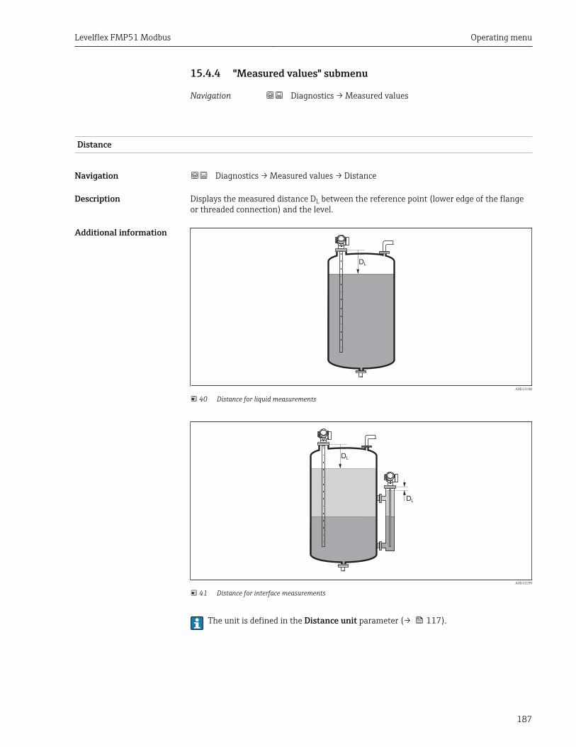
Levelflex FMP51 Modbus Operating menu
187
15.4.4 "Measured values" submenu
Navigation Diagnostics → Measured values
Distance
Navigation Diagnostics → Measured values → Distance
Description Displays the measured distance DL between the reference point (lower edge of the flangeor threaded connection) and the level.
Additional information
DL
A0013198
40 Distance for liquid measurements
DL
DL
A0013199
41 Distance for interface measurements
The unit is defined in the Distance unit parameter (→ 117).
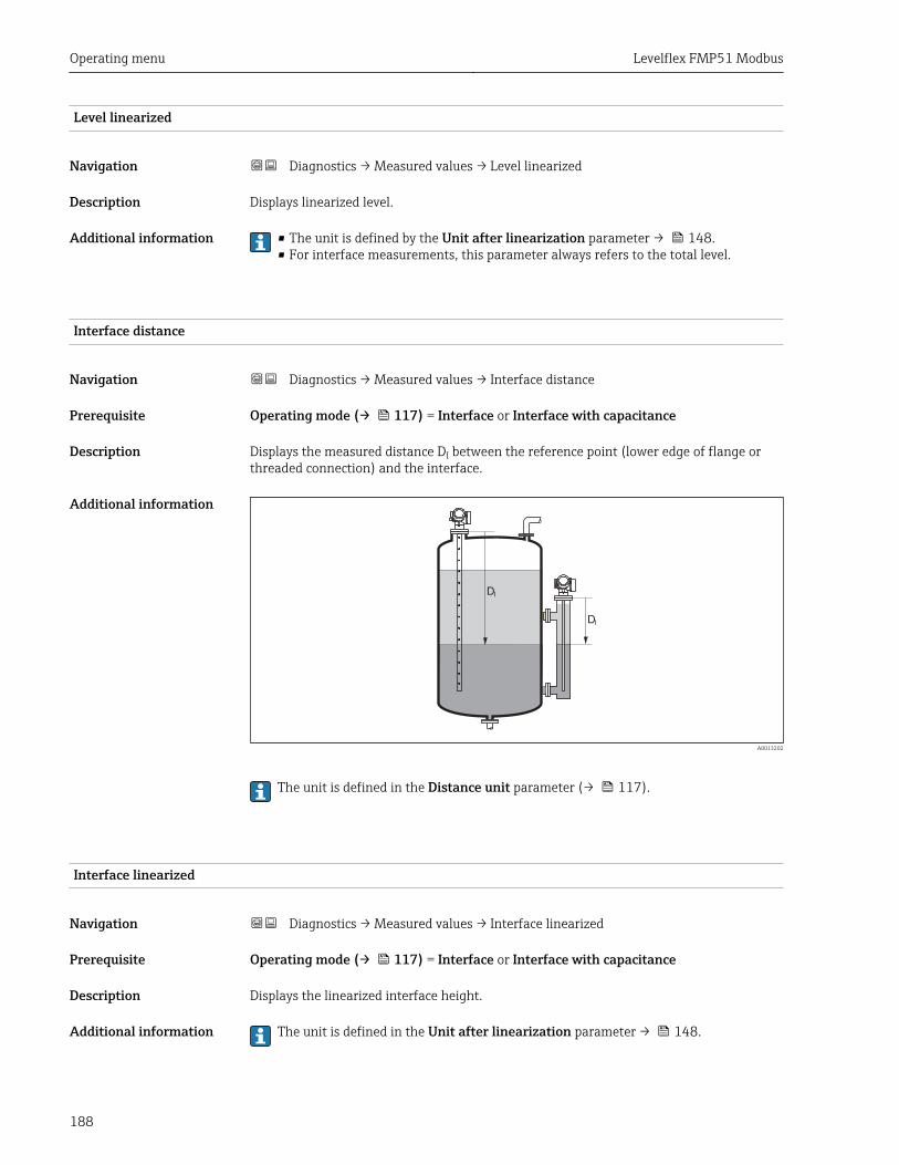
Operating menu Levelflex FMP51 Modbus
188
Level linearized
Navigation Diagnostics → Measured values → Level linearized
Description Displays linearized level.
Additional information • The unit is defined by the Unit after linearization parameter → 148.• For interface measurements, this parameter always refers to the total level.
Interface distance
Navigation Diagnostics → Measured values → Interface distance
Prerequisite Operating mode (→ 117) = Interface or Interface with capacitance
Description Displays the measured distance DI between the reference point (lower edge of flange orthreaded connection) and the interface.
Additional information
DI
DI
A0013202
The unit is defined in the Distance unit parameter (→ 117).
Interface linearized
Navigation Diagnostics → Measured values → Interface linearized
Prerequisite Operating mode (→ 117) = Interface or Interface with capacitance
Description Displays the linearized interface height.
Additional information The unit is defined in the Unit after linearization parameter → 148.
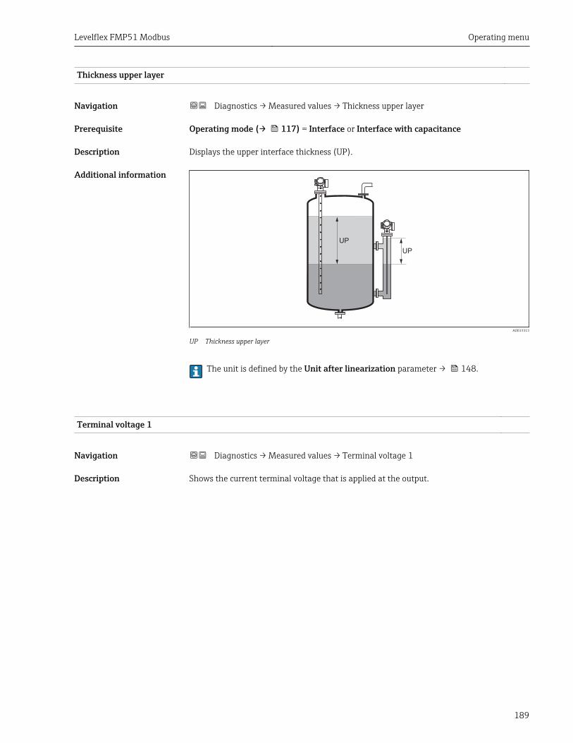
Levelflex FMP51 Modbus Operating menu
189
Thickness upper layer
Navigation Diagnostics → Measured values → Thickness upper layer
Prerequisite Operating mode (→ 117) = Interface or Interface with capacitance
Description Displays the upper interface thickness (UP).
Additional information
UP
UP
A0013313
UP Thickness upper layer
The unit is defined by the Unit after linearization parameter → 148.
Terminal voltage 1
Navigation Diagnostics → Measured values → Terminal voltage 1
Description Shows the current terminal voltage that is applied at the output.
Operating menu Levelflex FMP51 Modbus
190
15.4.5 "Data logging" submenu
Navigation Diagnostics → Data logging
Assign channel 1 to 4
Navigation Diagnostics → Data logging → Assign channel 1 to 4
Description Assign a process variable to logging channel.
Selection • Off• Level linearized• Distance• Unfiltered distance• Interface linearized *
• Interface distance *
• Unfiltered interface distance• Thickness upper layer *
• Current output 1• Measured current• Current output 2 *
• Terminal voltage• Electronic temperature• Measured capacitance *
• Absolute echo amplitude• Relative echo amplitude• Absolute interface amplitude *
• Relative interface amplitude *
• Absolute EOP amplitude• EOP shift• Noise of signal• Calculated DC value *
• Analog output adv. diagnostics 1• Analog output adv. diagnostics 2
Factory setting Off
Additional information A total of 1000 measured values can be logged. This means:• 1000 data points if 1 logging channel is used• 500 data points if 2 logging channels are used• 333 data points if 3 logging channels are used• 250 data points if 4 logging channels are used
If the maximum number of data points is reached, the oldest data points in the data logare cyclically overwritten in such a way that the last 1000, 500, 333 or 250 measuredvalues are always in the log (ring memory principle).
The logged data are deleted if a new option is selected in this parameter.
* Visibility depends on order options or device settings
Levelflex FMP51 Modbus Operating menu
191
Logging interval
Navigation Diagnostics → Data logging → Logging interval
Diagnostics → Data logging → Logging interval
Description Define the logging interval tlog for data logging. This value defines the time intervalbetween the individual data points in the memory.
User entry 1.0 to 3 600.0 s
Factory setting 30.0 s
Additional information This parameter defines the interval between the individual data points in the data log, andthus the maximum loggable process time T log :
• If 1 logging channel is used: T log = 1000 ⋅ t log• If 2 logging channels are used: T log = 500 ⋅ t log• If 3 logging channels are used: T log = 333 ⋅ t log• If 4 logging channels are used: T log = 250 ⋅ t log
Once this time elapses, the oldest data points in the data log are cyclically overwritten suchthat a time of T log always remains in the memory (ring memory principle).
The logged data are deleted if this parameter is changed.
Example
When using 1 logging channel• Tlog = 1000 ⋅ 1 s = 1 000 s ≈ 16.5 min• Tlog = 1000 ⋅ 10 s = 1 000 s ≈ 2.75 h• Tlog = 1000 ⋅ 80 s = 80 000 s ≈ 22 h• Tlog = 1000 ⋅ 3 600 s = 3 600 000 s ≈ 41 d
Clear logging data
Navigation Diagnostics → Data logging → Clear logging data
Diagnostics → Data logging → Clear logging data
Description Clear the entire logging data.
Selection • Cancel• Clear data
Factory setting Cancel
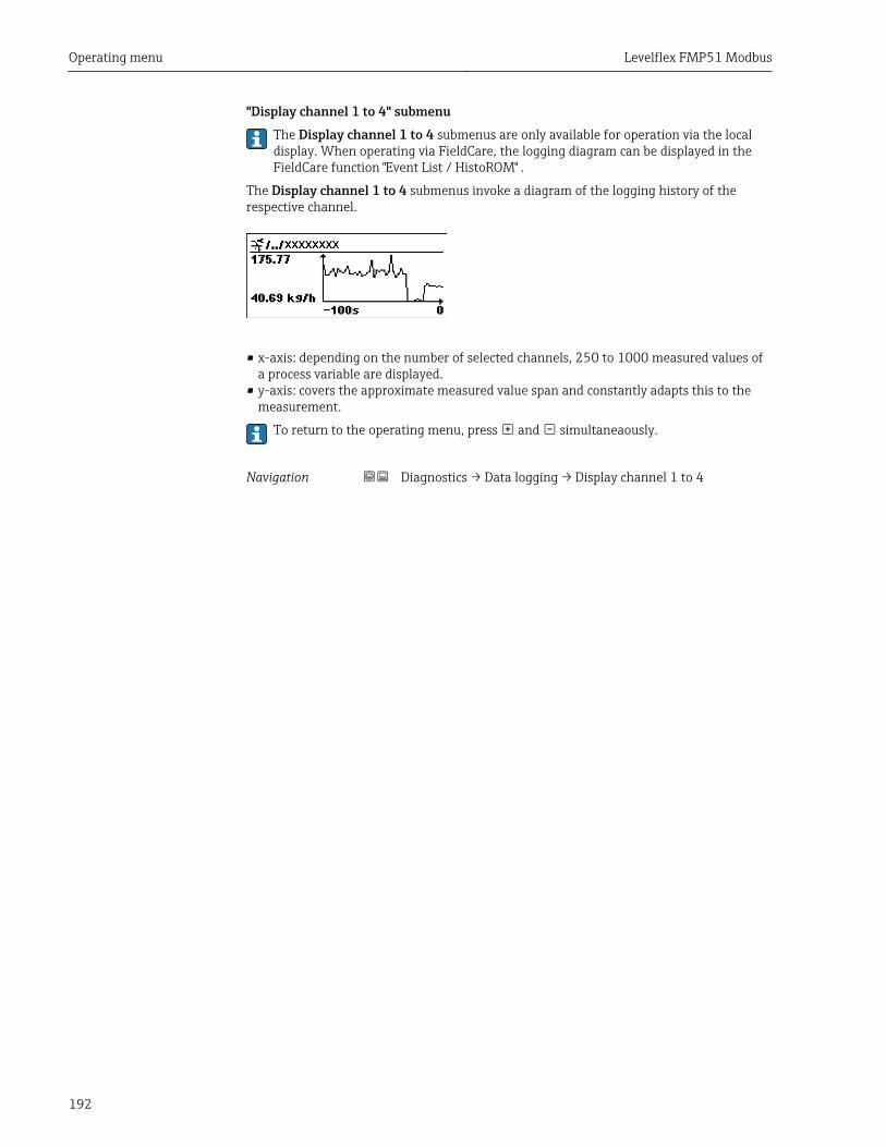
Operating menu Levelflex FMP51 Modbus
192
"Display channel 1 to 4" submenuThe Display channel 1 to 4 submenus are only available for operation via the localdisplay. When operating via FieldCare, the logging diagram can be displayed in theFieldCare function "Event List / HistoROM" .
The Display channel 1 to 4 submenus invoke a diagram of the logging history of therespective channel.
• x-axis: depending on the number of selected channels, 250 to 1000 measured values ofa process variable are displayed.
• y-axis: covers the approximate measured value span and constantly adapts this to themeasurement.
To return to the operating menu, press and simultaneaously.
Navigation Diagnostics → Data logging → Display channel 1 to 4
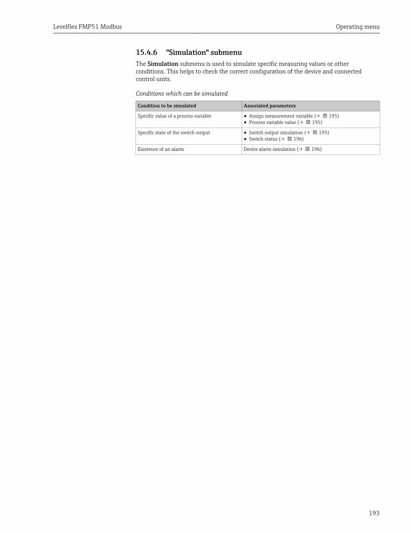
Levelflex FMP51 Modbus Operating menu
193
15.4.6 "Simulation" submenuThe Simulation submenu is used to simulate specific measuring values or otherconditions. This helps to check the correct configuration of the device and connectedcontrol units.
Conditions which can be simulated
Condition to be simulated Associated parameters
Specific value of a process variable • Assign measurement variable (→ 195)• Process variable value (→ 195)
Specific state of the switch output • Switch output simulation (→ 195)• Switch status (→ 196)
Existence of an alarm Device alarm simulation (→ 196)

Operating menu Levelflex FMP51 Modbus
194
Structure of the submenu
Navigation Expert → Diagnostics → Simulation
‣ Simulation
Assign measurement variable → 195
Process variable value → 195
Switch output simulation → 195
Switch status → 196
Device alarm simulation → 196
Levelflex FMP51 Modbus Operating menu
195
Description of parameters
Navigation Expert → Diagnostics → Simulation
Assign measurement variable
Navigation Expert → Diagnostics → Simulation → Assign measurement variable
Selection • Off• Level• Interface *
• Thickness upper layer *
• Level linearized• Interface linearized• Thickness linearized
Factory setting Off
Additional information • The value of the variable to be simulated is defined in the Process variable valueparameter (→ 195).
• If Assign measurement variable ≠ Off, a simulation is active. This is indicated by adiagnotic message of the Function check (C) category.
Process variable value
Navigation Expert → Diagnostics → Simulation → Process variable value
Prerequisite Assign measurement variable (→ 195) ≠ Off
User entry Signed floating-point number
Factory setting 0
Additional information Downstream measured value processing and the signal output use this simulation value. Inthis way, users can verify whether the measuring device has been configured correctly.
Switch output simulation
Navigation Expert → Diagnostics → Simulation → Switch output simulation
Description Switch the simulation of the switch output on and off.
Selection • Off• On
* Visibility depends on order options or device settings
Operating menu Levelflex FMP51 Modbus
196
Factory setting Off
Switch status
Navigation Expert → Diagnostics → Simulation → Switch status
Prerequisite Switch output simulation (→ 195) = On
Description Current status of the switch output.
Selection • Open• Closed
Factory setting Open
Additional information The switch status assumes the value defined in this parameter. This helps to check correctoperation of connected control units.
Device alarm simulation
Navigation Expert → Diagnostics → Simulation → Device alarm simulation
Description Switch the device alarm on and off.
Selection • Off• On
Factory setting Off
Additional information When selecting the On option, the device generates an alarm. This helps to check thecorrect output behavior of the device in the case of an alarm.
An active simulation is indicated by the diagnostic message C484 Failure modesimulation.
Diagnostic event simulation
Navigation Expert → Diagnostics → Simulation → Diagnostic event simulation
Description Select the diagnostic event to be simulated. Note: To terminate the simulation, select 'Off'.
Factory setting Off
Additional information When operated via the local display, the selection list can be filtered according to the eventcategories (Diagnostic event category parameter).
Levelflex FMP51 Modbus Operating menu
197
15.4.7 "Device check" submenu
Navigation Diagnostics → Device check
Start device check
Navigation Diagnostics → Device check → Start device check
Description Start a device check.
Selection • No• Yes
Factory setting No
Additional information In the case of a lost echo a device check can not be performed.
Result device check
Navigation Diagnostics → Device check → Result device check
Description Displays the result of the device check.
Additional information Meaning of the display options• Installation ok
Measurement possible without restrictions.• Accuracy reduced
A measurement is possible. However, the measuring accuracy may be reduced due to thesignal amplitudes.
• Measurement capability reducedA measurement is currently possible. Howerver, there is the risk of an echo loss. Checkthe mounting position of the device and the dielectric constant of the medium.
• Check not doneNo device check has been performed.
Last check time
Navigation Diagnostics → Device check → Last check time
Description Displays the operating time at which the last device check has been performed.
Operating menu Levelflex FMP51 Modbus
198
Level signal
Navigation Diagnostics → Device check → Level signal
Prerequisite Device check has been performed.
Description Displays result of the device check for the level signal.
User interface • Check not done• Check not OK• Check OK
Additional information For Level signal = Check not OK: Check the mounting position of the device and thedielectric constant of the medium.
Launch signal
Navigation Diagnostics → Device check → Launch signal
Prerequisite Device check has been performed.
Description Displays result of the display check for the launch signal.
User interface • Check not done• Check not OK• Check OK
Additional information For Launch signal = Check not OK: Check the mounting position of the device. In non-metallic vessels use a metal plate or a metal flange.
Interface signal
Navigation Diagnostics → Device check → Interface signal
Prerequisite • Operating mode (→ 117) = Interface or Interface with capacitance• Device check has been performed.
Description Displays result of the device check for the interface signal.
User interface • Check not done• Check not OK• Check OK
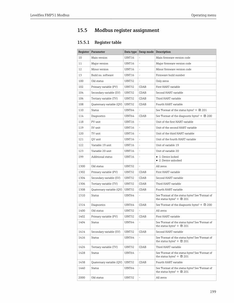
Levelflex FMP51 Modbus Operating menu
199
15.5 Modbus register assignment
15.5.1 Register table
Register Parameter Data type Swap mode Description
10 Main version UINT16 - Main firmware version code
11 Major version UINT16 - Major firmware version code
12 Minor version UINT16 - Minor firmware version code
13 Build no. software UINT16 - Firmware build number
100 Old status UINT32 - Only zeros
102 Primary variable (PV) UINT32 CDAB First HART variable
104 Secondary variable (SV) UINT32 CDAB Second HART variable
106 Tertiary variable (TV) UINT32 CDAB Third HART variable
108 Quaternary variable (QV) UINT32 CDAB Fourth HART variable
110 Status UINT64 - See "Format of the status bytes" → 201
114 Diagnostics UINT64 CDAB See "Format of the diagnostic bytes" → 200
118 PV unit UINT16 - Unit of the first HART variable
119 SV unit UINT16 - Unit of the second HART variable
120 TV unit UINT16 - Unit of the third HART variable
121 QV unit UINT16 - Unit of the fourth HART variable
122 Variable 19 unit UINT16 - Unit of variable 19
123 Variable 20 unit UINT16 - Unit of variable 20
199 Additional status UINT16 - • 1: Device locked• 2: Device unlocked
1300 Old status UINT32 - All zeros
1302 Primary variable (PV) UINT32 CDAB First HART variable
1304 Secondary variable (SV) UINT32 CDAB Second HART variable
1306 Tertiary variable (TV) UINT32 CDAB Third HART variable
1308 Quaternary variable (QV) UINT32 CDAB Fourth HART variable
1310 Status UINT64 - See "Format of the status bytes" See "Format ofthe status bytes" → 201
1314 Diagnostics UINT64 CDAB See "Format of the diagnostic bytes" → 200
1400 Old status UINT32 - All zeros
1402 Primary variable (PV) UINT32 CDAB First HART variable
1404 Status UINT64 - See "Format of the status bytes" See "Format ofthe status bytes" → 201
1414 Secondary variable (SV) UINT32 CDAB Second HART variable
1416 Status UINT64 - See "Format of the status bytes" See "Format ofthe status bytes" → 201
1426 Tertiary variable (TV) UINT32 CDAB Third HART variable
1428 Status UINT64 - See "Format of the status bytes" See "Format ofthe status bytes" → 201
1438 Quaternary variable (QV) UINT32 CDAB Fourth HART variable
1440 Status UINT64 - See "Format of the status bytes" See "Format ofthe status bytes" → 201
2000 Old status UINT32 - All zeros
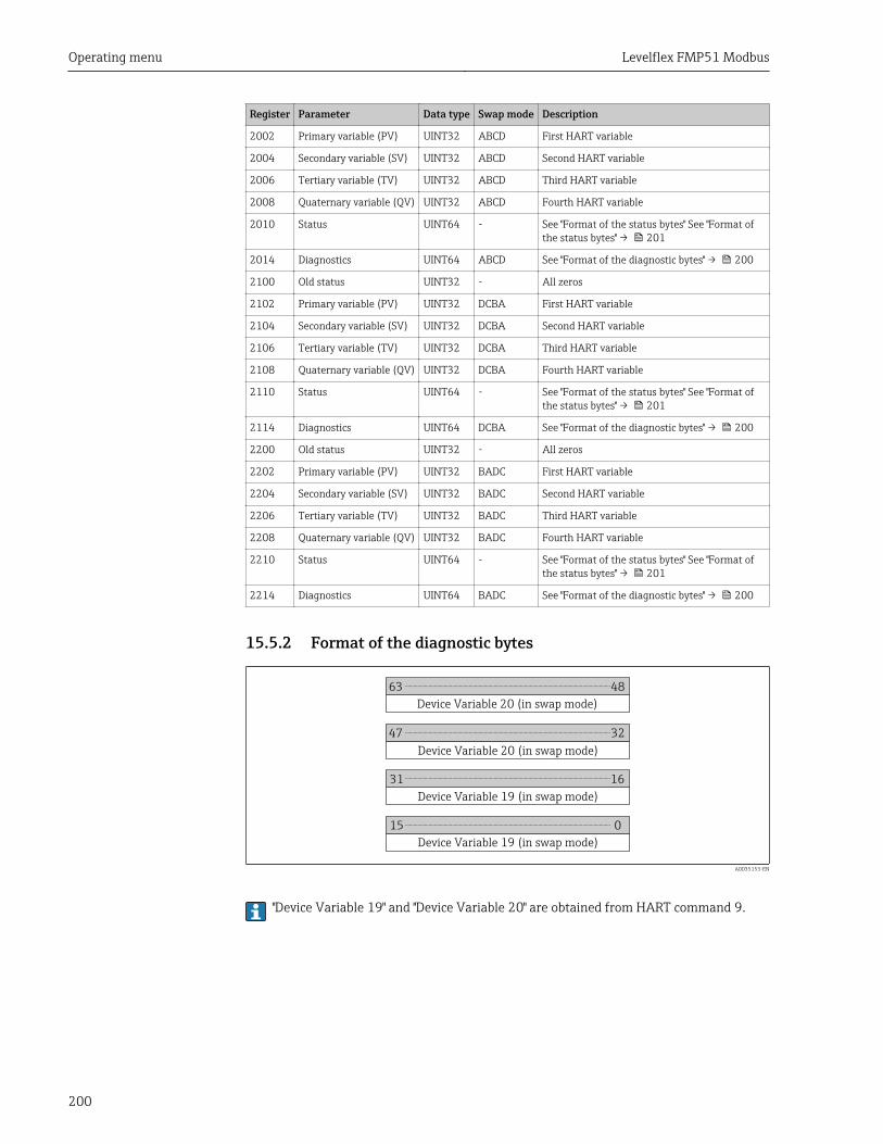
Operating menu Levelflex FMP51 Modbus
200
Register Parameter Data type Swap mode Description
2002 Primary variable (PV) UINT32 ABCD First HART variable
2004 Secondary variable (SV) UINT32 ABCD Second HART variable
2006 Tertiary variable (TV) UINT32 ABCD Third HART variable
2008 Quaternary variable (QV) UINT32 ABCD Fourth HART variable
2010 Status UINT64 - See "Format of the status bytes" See "Format ofthe status bytes" → 201
2014 Diagnostics UINT64 ABCD See "Format of the diagnostic bytes" → 200
2100 Old status UINT32 - All zeros
2102 Primary variable (PV) UINT32 DCBA First HART variable
2104 Secondary variable (SV) UINT32 DCBA Second HART variable
2106 Tertiary variable (TV) UINT32 DCBA Third HART variable
2108 Quaternary variable (QV) UINT32 DCBA Fourth HART variable
2110 Status UINT64 - See "Format of the status bytes" See "Format ofthe status bytes" → 201
2114 Diagnostics UINT64 DCBA See "Format of the diagnostic bytes" → 200
2200 Old status UINT32 - All zeros
2202 Primary variable (PV) UINT32 BADC First HART variable
2204 Secondary variable (SV) UINT32 BADC Second HART variable
2206 Tertiary variable (TV) UINT32 BADC Third HART variable
2208 Quaternary variable (QV) UINT32 BADC Fourth HART variable
2210 Status UINT64 - See "Format of the status bytes" See "Format ofthe status bytes" → 201
2214 Diagnostics UINT64 BADC See "Format of the diagnostic bytes" → 200
15.5.2 Format of the diagnostic bytes
Device Variable 20 (in swap mode)
63 48
47 32
31 16
15 0
Device Variable 20 (in swap mode)
Device Variable 19 (in swap mode)
Device Variable 19 (in swap mode)
A0035153-EN
"Device Variable 19" and "Device Variable 20" are obtained from HART command 9.
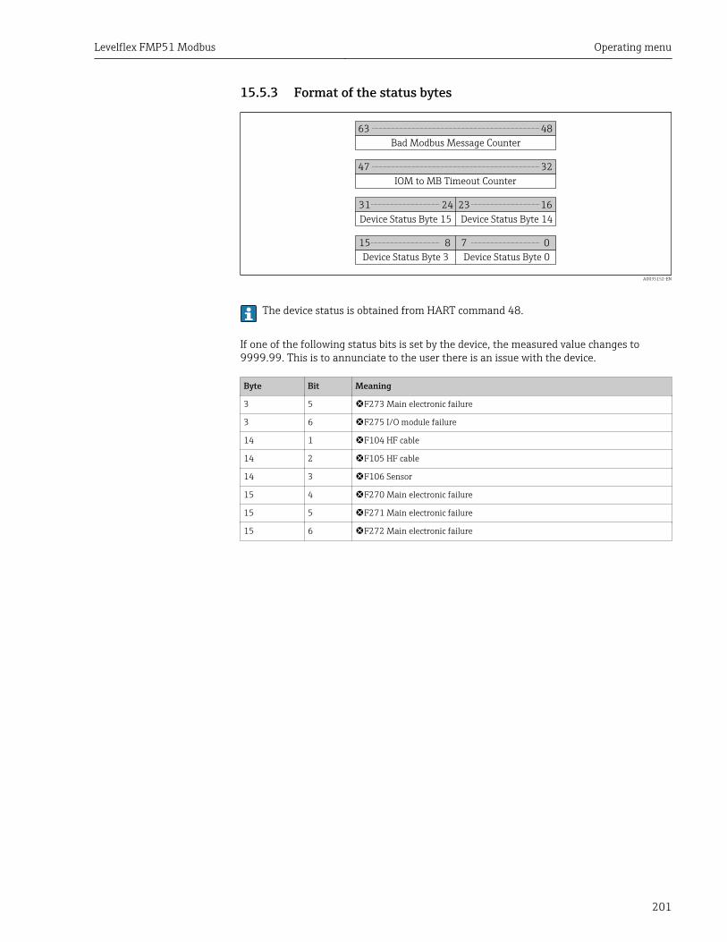
Levelflex FMP51 Modbus Operating menu
201
15.5.3 Format of the status bytes
Bad Modbus Message Counter
63 48
IOM to MB Timeout Counter
47 32
Device Status Byte 15
31 16
15 8
24 23
Device Status Byte 14
Device Status Byte 3 Device Status Byte 0
07
A0035152-EN
The device status is obtained from HART command 48.
If one of the following status bits is set by the device, the measured value changes to9999.99. This is to annunciate to the user there is an issue with the device.
Byte Bit Meaning
3 5 F273 Main electronic failure
3 6 F275 I/O module failure
14 1 F104 HF cable
14 2 F105 HF cable
14 3 F106 Sensor
15 4 F270 Main electronic failure
15 5 F271 Main electronic failure
15 6 F272 Main electronic failure
Index Levelflex FMP51 Modbus
202
Index
AAccess authorization to parameters
Read access . . . . . . . . . . . . . . . . . . . . . . . . . . . . . 59Write access . . . . . . . . . . . . . . . . . . . . . . . . . . . . . 59
Access code . . . . . . . . . . . . . . . . . . . . . . . . . . . . . . . . 59Incorrect input . . . . . . . . . . . . . . . . . . . . . . . . . . . 59
Access status display (Parameter) . . . . . . . . . . . . . . 132Access status tooling (Parameter) . . . . . . . . . . . . . . 131Accessories
Communication specific . . . . . . . . . . . . . . . . . . . 102Device specific . . . . . . . . . . . . . . . . . . . . . . . . . . . 96Service specific . . . . . . . . . . . . . . . . . . . . . . . . . . 102
Activate table (Parameter) . . . . . . . . . . . . . . . . . . . . 153Actual diagnostics (Parameter) . . . . . . . . . . . . . . . . 180Administration (Submenu) . . . . . . . . . . . . . . . . . . . 177Advanced process conditions (Parameter) . . . . . . . . 135Advanced setup (Submenu) . . . . . . . . . . . . . . . . . . . 131Application . . . . . . . . . . . . . . . . . . . . . . . . . . . . . . . . . 9
Residual risk . . . . . . . . . . . . . . . . . . . . . . . . . . . . . 9Assign channel 1 to 4 (Parameter) . . . . . . . . . . . . . . 190Assign diagnostic behavior (Parameter) . . . . . . . . . . 162Assign limit (Parameter) . . . . . . . . . . . . . . . . . . . . . 162Assign measurement variable (Parameter) . . . . . . . . 195Assign status (Parameter) . . . . . . . . . . . . . . . . . . . . 162Automatic DC calculation (Wizard) . . . . . . . . . . . . . 143
BBacklight (Parameter) . . . . . . . . . . . . . . . . . . . . . . . 172Backup state (Parameter) . . . . . . . . . . . . . . . . . . . . 175Blocking distance (Parameter) . . . . . . . . . 136, 139, 156Bypass . . . . . . . . . . . . . . . . . . . . . . . . . . . . . . . . . . . 31
CCalculated DC value (Parameter) . . . . . . . . . . . . . . . 141CE mark . . . . . . . . . . . . . . . . . . . . . . . . . . . . . . . . . . 10Cleaning . . . . . . . . . . . . . . . . . . . . . . . . . . . . . . . . . . 94Clear logging data (Parameter) . . . . . . . . . . . . . . . . 191Coax probe
Design . . . . . . . . . . . . . . . . . . . . . . . . . . . . . . . . . 11Coax probes
Bending strength . . . . . . . . . . . . . . . . . . . . . . . . . 22Shortening . . . . . . . . . . . . . . . . . . . . . . . . . . . . . . 41
Comparison result (Parameter) . . . . . . . . . . . . . . . . 175Configuration backup display (Submenu) . . . . . . . . . 174Configuration management (Parameter) . . . . . . . . . 174Configuration of a level measurement . . . . . . . . . . . . 74Configuration of an interface measurement . . . . . . . . 76Confirm access code (Parameter) . . . . . . . . . . . . . . . 179Confirm distance (Parameter) . . . . . . . . . . . . . 127, 130Confirm probe length (Parameter) . . . . . . . . . . 159, 160Context menu . . . . . . . . . . . . . . . . . . . . . . . . . . . . . . 70Contrast display (Parameter) . . . . . . . . . . . . . . . . . . 173Customer value (Parameter) . . . . . . . . . . . . . . . . . . 153
DData logging (Submenu) . . . . . . . . . . . . . . . . . . . . . 190
DC value (Parameter) . . . . . . . . . . . . . . . . 125, 141, 143DC value lower medium (Parameter) . . . . . . . . . . . . 138Decimal places 1 (Parameter) . . . . . . . . . . . . . . . . . 169Decimal places menu (Parameter) . . . . . . . . . . . . . . 172Declaration of Conformity . . . . . . . . . . . . . . . . . . . . . 10Define access code . . . . . . . . . . . . . . . . . . . . . . . . . . . 60Define access code (Parameter) . . . . . . . . . . . . 177, 179Define access code (Wizard) . . . . . . . . . . . . . . . . . . 179Designated use . . . . . . . . . . . . . . . . . . . . . . . . . . . . . . 9Device alarm simulation (Parameter) . . . . . . . . . . . . 196Device check (Submenu) . . . . . . . . . . . . . . . . . . . . . 197Device ID (Parameter) . . . . . . . . . . . . . . . . . . . . . . . 185Device information (Submenu) . . . . . . . . . . . . . . . . 184Device name (Parameter) . . . . . . . . . . . . . . . . . . . . 184Device replacement . . . . . . . . . . . . . . . . . . . . . . . . . . 95Device reset (Parameter) . . . . . . . . . . . . . . . . . . . . . 177Device revision (Parameter) . . . . . . . . . . . . . . . . . . . 185Device tag (Parameter) . . . . . . . . . . . . . . . . . . 117, 184Device type (Parameter) . . . . . . . . . . . . . . . . . . . . . 186Diagnostic event
In the operating tool . . . . . . . . . . . . . . . . . . . . . . . 89Diagnostic event simulation (Parameter) . . . . . . . . . 196Diagnostic events . . . . . . . . . . . . . . . . . . . . . . . . . . . 86Diagnostic list . . . . . . . . . . . . . . . . . . . . . . . . . . . . . . 90Diagnostic list (Submenu) . . . . . . . . . . . . . . . . . . . . 182Diagnostic message . . . . . . . . . . . . . . . . . . . . . . . . . . 86Diagnostics
Symbols . . . . . . . . . . . . . . . . . . . . . . . . . . . . . . . . 86Diagnostics (Menu) . . . . . . . . . . . . . . . . . . . . . . . . . 180Diagnostics 1 (Parameter) . . . . . . . . . . . . . . . . . . . . 182Diagnostics event . . . . . . . . . . . . . . . . . . . . . . . . . . . 87Diameter (Parameter) . . . . . . . . . . . . . . . . . . . . . . . 150DIP switch
see Write protection switchDisplay (Submenu) . . . . . . . . . . . . . . . . . . . . . . . . . 167Display and operating module FHX50 . . . . . . . . . . . . 55Display channel 1 to 4 (Submenu) . . . . . . . . . . . . . . 192Display damping (Parameter) . . . . . . . . . . . . . . . . . 170Display interval (Parameter) . . . . . . . . . . . . . . . . . . 170Display module . . . . . . . . . . . . . . . . . . . . . . . . . . . . . 64Display symbols for submenus . . . . . . . . . . . . . . . . . . 65Display symbols for the locking state . . . . . . . . . . . . . 65Disposal . . . . . . . . . . . . . . . . . . . . . . . . . . . . . . . . . . 95Distance (Parameter) . . . . . . . . . . . . . . . . 122, 130, 187Distance to upper connection (Parameter) . . . . . . . . 124Distance unit (Parameter) . . . . . . . . . . . . . . . . . . . . 117Document
Function . . . . . . . . . . . . . . . . . . . . . . . . . . . . . . . . 5Document function . . . . . . . . . . . . . . . . . . . . . . . . . . . 5
EElectrical connection
Commubox FXA291 . . . . . . . . . . . . . . . . . . . . . . . 56Operating tools
Via service interface (CDI) . . . . . . . . . . . . . . . . 56
Levelflex FMP51 Modbus Index
203
Electronics housingDesign . . . . . . . . . . . . . . . . . . . . . . . . . . . . . . . . . 12
Empty calibration (Parameter) . . . . . . . . . . . . . . . . . 119Enter access code (Parameter) . . . . . . . . . . . . . . . . . 132Envelope curve display . . . . . . . . . . . . . . . . . . . . . . . . 71Event history . . . . . . . . . . . . . . . . . . . . . . . . . . . . . . . 90Event level
Explanation . . . . . . . . . . . . . . . . . . . . . . . . . . . . . 86Symbols . . . . . . . . . . . . . . . . . . . . . . . . . . . . . . . . 86
Event list (Submenu) . . . . . . . . . . . . . . . . . . . . . . . . 183Event logbook (Submenu) . . . . . . . . . . . . . . . . . . . . 183Event text . . . . . . . . . . . . . . . . . . . . . . . . . . . . . . . . . 87Events list . . . . . . . . . . . . . . . . . . . . . . . . . . . . . . . . . 90Extended order code 1 (Parameter) . . . . . . . . . . . . . 185Exterior cleaning . . . . . . . . . . . . . . . . . . . . . . . . . . . . 94External mounting . . . . . . . . . . . . . . . . . . . . . . . . . . 37
FFailure mode (Parameter) . . . . . . . . . . . . . . . . . . . . 165FHX50 . . . . . . . . . . . . . . . . . . . . . . . . . . . . . . . . . . . 55Filter options (Parameter) . . . . . . . . . . . . . . . . . . . . 183Filtering the event logbook . . . . . . . . . . . . . . . . . . . . 91Firmware version (Parameter) . . . . . . . . . . . . . . . . . 184Flange . . . . . . . . . . . . . . . . . . . . . . . . . . . . . . . . . . . 42Format display (Parameter) . . . . . . . . . . . . . . . . . . . 167Free text (Parameter) . . . . . . . . . . . . . . . . . . . . . . . 149Full calibration (Parameter) . . . . . . . . . . . . . . . . . . . 120
HHardware write protection . . . . . . . . . . . . . . . . . . . . . 61Header (Parameter) . . . . . . . . . . . . . . . . . . . . . . . . 170Header text (Parameter) . . . . . . . . . . . . . . . . . . . . . 171Heat insulation . . . . . . . . . . . . . . . . . . . . . . . . . . . . . 39Housing
Design . . . . . . . . . . . . . . . . . . . . . . . . . . . . . . . . . 12Turning . . . . . . . . . . . . . . . . . . . . . . . . . . . . . . . . 45
IInput mask . . . . . . . . . . . . . . . . . . . . . . . . . . . . . . . . 68Interface (Parameter) . . . . . . . . . . . . . . . . . . . . . . . 126Interface (Submenu) . . . . . . . . . . . . . . . . . . . . . . . . 138Interface distance (Parameter) . . . . . . . . . . . . . 127, 188Interface linearized (Parameter) . . . . . . . . . . . . 150, 188Interface measurement configuration . . . . . . . . . . . . . 76Interface signal (Parameter) . . . . . . . . . . . . . . . . . . 198Intermediate height (Parameter) . . . . . . . . . . . . . . . 151Invert output signal (Parameter) . . . . . . . . . . . . . . . 165
KKeypad lock
Disabling . . . . . . . . . . . . . . . . . . . . . . . . . . . . . . . 63Switching on . . . . . . . . . . . . . . . . . . . . . . . . . . . . 63
LLanguage (Parameter) . . . . . . . . . . . . . . . . . . . . . . . 167Last backup (Parameter) . . . . . . . . . . . . . . . . . . . . . 174Last check time (Parameter) . . . . . . . . . . . . . . . . . . 197Launch signal (Parameter) . . . . . . . . . . . . . . . . . . . . 198Level (Parameter) . . . . . . . . . . . . . . . . . . . . . . 121, 153Level (Submenu) . . . . . . . . . . . . . . . . . . . . . . . . . . . 133
Level correction (Parameter) . . . . . . . . . . . . . . 137, 140Level linearized (Parameter) . . . . . . . . . . . . . . 149, 188Level measurement configuration . . . . . . . . . . . . . . . 74Level signal (Parameter) . . . . . . . . . . . . . . . . . . . . . 198Level unit (Parameter) . . . . . . . . . . . . . . . . . . . 136, 139Linearization (Submenu) . . . . . . . . . . . . . 145, 146, 147Linearization type (Parameter) . . . . . . . . . . . . . . . . 147Local display . . . . . . . . . . . . . . . . . . . . . . . . . . . . . . . 54
see Diagnostics messagesee In alarm condition
Locking status (Parameter) . . . . . . . . . . . . . . . . . . . 131Logging interval (Parameter) . . . . . . . . . . . . . . . . . . 191
MMaintenance . . . . . . . . . . . . . . . . . . . . . . . . . . . . . . . 94Manage device configuration . . . . . . . . . . . . . . . . . . . 81Manual thickness upper layer (Parameter) . . . . 140, 143Manufacturer ID (Parameter) . . . . . . . . . . . . . . . . . 186Mapping (Wizard) . . . . . . . . . . . . . . . . . . . . . . . . . . 130Mapping end point (Parameter) . . . . . . . . . . . . 128, 130Maximum value (Parameter) . . . . . . . . . . . . . . . . . . 150Measured materials . . . . . . . . . . . . . . . . . . . . . . . . . . . 9Measured thickness upper layer (Parameter) . . . . . . 141Measured value symbols . . . . . . . . . . . . . . . . . . . . . . 66Measured values (Submenu) . . . . . . . . . . . . . . . . . . 187Medium group (Parameter) . . . . . . . . . . . . . . . . . . . 118Medium property (Parameter) . . . . . . . . . . . . . . . . . 133Medium type (Parameter) . . . . . . . . . . . . . . . . . . . . 133Menu
Diagnostics . . . . . . . . . . . . . . . . . . . . . . . . . . . . 180Setup . . . . . . . . . . . . . . . . . . . . . . . . . . . . . . . . . 117
Mounting position for level measurements . . . . . . . . . 17
NNon-metallic vessels . . . . . . . . . . . . . . . . . . . . . . . . . 36Number format (Parameter) . . . . . . . . . . . . . . . . . . 171
OOperating elements
Diagnostics message . . . . . . . . . . . . . . . . . . . . . . . 87Operating mode (Parameter) . . . . . . . . . . . . . . . . . . 117Operating module . . . . . . . . . . . . . . . . . . . . . . . . . . . 64Operating time (Parameter) . . . . . . . . . . . . . . . 174, 181Operating time from restart (Parameter) . . . . . . . . . 181Operational safety . . . . . . . . . . . . . . . . . . . . . . . . . . . 10Order code (Parameter) . . . . . . . . . . . . . . . . . . . . . . 185Output echo lost (Parameter) . . . . . . . . . . . . . . . . . . 155Overvoltage protection
General information . . . . . . . . . . . . . . . . . . . . . . . 51
PPresent mapping (Parameter) . . . . . . . . . . . . . . . . . 128Present probe length (Parameter) . . . . . . . . . . 158, 160Previous diagnostics (Parameter) . . . . . . . . . . . . . . . 180Probe grounded (Parameter) . . . . . . . . . . . . . . . . . . 158Probe length correction (Wizard) . . . . . . . . . . . . . . . 160Probe settings (Submenu) . . . . . . . . . . . . . . . . . . . . 158Process property (Parameter) . . . . . . . . . . . . . . 134, 138Process variable value (Parameter) . . . . . . . . . . . . . . 195Product safety . . . . . . . . . . . . . . . . . . . . . . . . . . . . . . 10
Index Levelflex FMP51 Modbus
204
RRamp at echo lost (Parameter) . . . . . . . . . . . . . . . . . 156Read access . . . . . . . . . . . . . . . . . . . . . . . . . . . . . . . . 59Record map (Parameter) . . . . . . . . . . . . . . . . . 129, 130Registered trademarks . . . . . . . . . . . . . . . . . . . . . . . . 13Remedial measures
Calling up . . . . . . . . . . . . . . . . . . . . . . . . . . . . . . 88Closing . . . . . . . . . . . . . . . . . . . . . . . . . . . . . . . . . 88
Remote operation . . . . . . . . . . . . . . . . . . . . . . . . . . . 55Replacing a device . . . . . . . . . . . . . . . . . . . . . . . . . . . 95Requirements for personnel . . . . . . . . . . . . . . . . . . . . . 9Result device check (Parameter) . . . . . . . . . . . . . . . . 197Rod probe
Design . . . . . . . . . . . . . . . . . . . . . . . . . . . . . . . . . 11Rod probes
Bending strength . . . . . . . . . . . . . . . . . . . . . . . . . 21Shortening . . . . . . . . . . . . . . . . . . . . . . . . . . . . . . 40
Rope probeDesign . . . . . . . . . . . . . . . . . . . . . . . . . . . . . . . . . 11
Rope probesShortening . . . . . . . . . . . . . . . . . . . . . . . . . . . . . . 40Tensile load . . . . . . . . . . . . . . . . . . . . . . . . . . . . . 21
SSafety instructions
Basic . . . . . . . . . . . . . . . . . . . . . . . . . . . . . . . . . . . 9Safety settings (Submenu) . . . . . . . . . . . . . . . . . . . . 155Securing coax probes . . . . . . . . . . . . . . . . . . . . . . . . . 30Securing rod probes . . . . . . . . . . . . . . . . . . . . . . . . . . 29Securing rope probes . . . . . . . . . . . . . . . . . . . . . . . . . 27Seilsonden
Montage . . . . . . . . . . . . . . . . . . . . . . . . . . . . . . . 42Separator (Parameter) . . . . . . . . . . . . . . . . . . . . . . . 171Serial number (Parameter) . . . . . . . . . . . . . . . . . . . 184Setting the operating language . . . . . . . . . . . . . . . . . 73Settings
Manage device configuration . . . . . . . . . . . . . . . . 81Operating language . . . . . . . . . . . . . . . . . . . . . . . 73
Setup (Menu) . . . . . . . . . . . . . . . . . . . . . . . . . . . . . 117Signal quality (Parameter) . . . . . . . . . . . . . . . . . . . . 123Simulation (Submenu) . . . . . . . . . . . . . . . . . . . 194, 195Start device check (Parameter) . . . . . . . . . . . . . . . . . 197Status signals . . . . . . . . . . . . . . . . . . . . . . . . . . . 65, 86Stilling well . . . . . . . . . . . . . . . . . . . . . . . . . . . . . . . . 31Störungsbehebung . . . . . . . . . . . . . . . . . . . . . . . . . . 83Submenu
Administration . . . . . . . . . . . . . . . . . . . . . . . . . . 177Advanced setup . . . . . . . . . . . . . . . . . . . . . . . . . 131Configuration backup display . . . . . . . . . . . . . . . 174Data logging . . . . . . . . . . . . . . . . . . . . . . . . . . . 190Device check . . . . . . . . . . . . . . . . . . . . . . . . . . . 197Device information . . . . . . . . . . . . . . . . . . . . . . . 184Diagnostic list . . . . . . . . . . . . . . . . . . . . . . . . . . 182Display . . . . . . . . . . . . . . . . . . . . . . . . . . . . . . . . 167Display channel 1 to 4 . . . . . . . . . . . . . . . . . . . . 192Event list . . . . . . . . . . . . . . . . . . . . . . . . . . . . . . 183Event logbook . . . . . . . . . . . . . . . . . . . . . . . . . . 183Events list . . . . . . . . . . . . . . . . . . . . . . . . . . . . . . 90Interface . . . . . . . . . . . . . . . . . . . . . . . . . . . . . . 138
Level . . . . . . . . . . . . . . . . . . . . . . . . . . . . . . . . . 133Linearization . . . . . . . . . . . . . . . . . . . 145, 146, 147Measured values . . . . . . . . . . . . . . . . . . . . . . . . 187Probe settings . . . . . . . . . . . . . . . . . . . . . . . . . . 158Safety settings . . . . . . . . . . . . . . . . . . . . . . . . . . 155Simulation . . . . . . . . . . . . . . . . . . . . . . . . . 194, 195Switch output . . . . . . . . . . . . . . . . . . . . . . . . . . . 161
Switch output (Submenu) . . . . . . . . . . . . . . . . . . . . 161Switch output function (Parameter) . . . . . . . . . . . . . 161Switch output simulation (Parameter) . . . . . . . . . . . 195Switch status (Parameter) . . . . . . . . . . . . . . . . 165, 196Switch-off delay (Parameter) . . . . . . . . . . . . . . . . . . 165Switch-off value (Parameter) . . . . . . . . . . . . . . . . . . 164Switch-on delay (Parameter) . . . . . . . . . . . . . . . . . . 164Switch-on value (Parameter) . . . . . . . . . . . . . . . . . . 163Symbols
For correction . . . . . . . . . . . . . . . . . . . . . . . . . . . . 68In the text and numeric editor . . . . . . . . . . . . . . . . 68
System components . . . . . . . . . . . . . . . . . . . . . . . . . 102
TTable mode (Parameter) . . . . . . . . . . . . . . . . . . . . . 151Table number (Parameter) . . . . . . . . . . . . . . . . . . . . 152Tank level (Parameter) . . . . . . . . . . . . . . . . . . . . . . 124Tank type (Parameter) . . . . . . . . . . . . . . . . . . . . . . 118Terminal voltage 1 (Parameter) . . . . . . . . . . . . . . . . 189Thickness upper layer (Parameter) . . . . . . . . . . . . . . 189Threaded connection . . . . . . . . . . . . . . . . . . . . . . . . . 42Timestamp (Parameter) . . . . . . . . . . . . . . 180, 181, 182Tools . . . . . . . . . . . . . . . . . . . . . . . . . . . . . . . . . . . . 40Transmitter
Turning the display module . . . . . . . . . . . . . . . . . 45Transmitter housing
Turning . . . . . . . . . . . . . . . . . . . . . . . . . . . . . . . . 45Tube diameter (Parameter) . . . . . . . . . . . . . . . . . . . 118Turning the display module . . . . . . . . . . . . . . . . . . . . 45
UUnderground tanks . . . . . . . . . . . . . . . . . . . . . . . . . . 34Unit after linearization (Parameter) . . . . . . . . . . . . . 148Use calculated DC value (Parameter) . . . . . . . . 142, 143
VValue 1 display (Parameter) . . . . . . . . . . . . . . . . . . 169Value echo lost (Parameter) . . . . . . . . . . . . . . . . . . . 155
WWizard
Automatic DC calculation . . . . . . . . . . . . . . . . . . 143Define access code . . . . . . . . . . . . . . . . . . . . . . . 179Mapping . . . . . . . . . . . . . . . . . . . . . . . . . . . . . . 130Probe length correction . . . . . . . . . . . . . . . . . . . 160
Workplace safety . . . . . . . . . . . . . . . . . . . . . . . . . . . . 9Write access . . . . . . . . . . . . . . . . . . . . . . . . . . . . . . . 59Write protection
Via access code . . . . . . . . . . . . . . . . . . . . . . . . . . . 60Via write protection switch . . . . . . . . . . . . . . . . . . 61
Write protection switch . . . . . . . . . . . . . . . . . . . . . . . 61