levelflex …
TRANSCRIPT

Products Solutions Services
Description of Device ParametersLevelflex FMP50, FMP51, FMP52,FMP53, FMP54, FMP55, FMP56,FMP57PROFIBUS PAGuided wave radar
GP01001F/00/EN/13.1471272188
01.01.zz


Levelflex FMP50, FMP51, FMP52, FMP53, FMP54, FMP55, FMP56, FMP57 PROFIBUS PA Table of contents
Endress+Hauser 3
Table of contents
1 Important document information . . . . 41.1 Document function . . . . . . . . . . . . . . . . . . . . . 41.2 Symbols . . . . . . . . . . . . . . . . . . . . . . . . . . . . . . 4
1.2.1 Symbols for certain types ofinformation . . . . . . . . . . . . . . . . . . . . 4
1.2.2 Symbols in graphics . . . . . . . . . . . . . . . 4
2 Basic principles . . . . . . . . . . . . . . . . . . . . . 52.1 Time-of-Flight principle . . . . . . . . . . . . . . . . . . 52.2 Interface measurement . . . . . . . . . . . . . . . . . . 62.3 Envelope curve . . . . . . . . . . . . . . . . . . . . . . . . 72.4 Mapping and subtracted curve . . . . . . . . . . . . . 82.5 Echo tracking . . . . . . . . . . . . . . . . . . . . . . . . . 82.6 Capacitance measurement (only for
FMP55) . . . . . . . . . . . . . . . . . . . . . . . . . . . . . . 9
3 Overview of the operating menu . . . . 10
4 "Expert" menu . . . . . . . . . . . . . . . . . . . . . 284.1 Structure of the menu . . . . . . . . . . . . . . . . . . 284.2 Description of parameters . . . . . . . . . . . . . . . 294.3 "System" submenu . . . . . . . . . . . . . . . . . . . . . 32
4.3.1 Structure of the submenu . . . . . . . . . 324.3.2 "Display" submenu . . . . . . . . . . . . . . . 334.3.3 "Configuration backup display"
submenu . . . . . . . . . . . . . . . . . . . . . . 414.3.4 "Administration" submenu . . . . . . . . . 46
4.4 "Sensor" submenu . . . . . . . . . . . . . . . . . . . . . . 504.4.1 Structure of the submenu . . . . . . . . . 504.4.2 Description of parameters . . . . . . . . . 524.4.3 "Medium" submenu . . . . . . . . . . . . . . 574.4.4 "Level" submenu . . . . . . . . . . . . . . . . . 624.4.5 "Linearization" submenu . . . . . . . . . . . 744.4.6 "Information" submenu . . . . . . . . . . . . 854.4.7 "Sensor properties" submenu . . . . . . . 924.4.8 "Distance" submenu . . . . . . . . . . . . . . 964.4.9 "Gas phase compensation" submenu 1044.4.10 "Sensor diagnostics" submenu . . . . . . 1144.4.11 "Safety settings" submenu . . . . . . . . . 1194.4.12 "Envelope curve" submenu . . . . . . . . 1304.4.13 "Mapping" submenu . . . . . . . . . . . . . 1324.4.14 "EOP evaluation" submenu . . . . . . . . 1414.4.15 "Echo tracking" submenu . . . . . . . . . 1464.4.16 "Interface" submenu . . . . . . . . . . . . . 152
4.5 "Output" submenu . . . . . . . . . . . . . . . . . . . . . 1654.5.1 Structure of the submenu . . . . . . . . 1654.5.2 "Switch output" submenu . . . . . . . . . 166
4.6 "Communication" submenu . . . . . . . . . . . . . . 1734.6.1 Structure of the submenu . . . . . . . . 1734.6.2 "PROFIBUS PA configuration"
submenu . . . . . . . . . . . . . . . . . . . . . 1744.6.3 "PROFIBUS PA info" submenu . . . . . . 1774.6.4 "Physical block" submenu . . . . . . . . . 180
4.7 "Analog input 1 to 6" submenu . . . . . . . . . . . 1884.7.1 Overview . . . . . . . . . . . . . . . . . . . . . 1884.7.2 Structure of the submenu . . . . . . . . 1894.7.3 Description of parameters . . . . . . . . 191
4.8 "Discrete input 1 to 4" submenu . . . . . . . . . . . 2054.8.1 Übersicht . . . . . . . . . . . . . . . . . . . . 2054.8.2 Structure of the submenu . . . . . . . . 2064.8.3 Description of parameters . . . . . . . . 208
4.9 "Analog output 1 to 4" submenu . . . . . . . . . . 2154.9.1 Overview . . . . . . . . . . . . . . . . . . . . . 2154.9.2 Structure of the submenu . . . . . . . . 2174.9.3 Description of parameters . . . . . . . . 219
4.10 "Discrete output 1 to 4" submenu . . . . . . . . . . 2304.10.1 Overview . . . . . . . . . . . . . . . . . . . . . 2304.10.2 Structure of the submenu . . . . . . . . 2314.10.3 Description of parameters . . . . . . . . 233
4.11 "Diagnostics" submenu . . . . . . . . . . . . . . . . . 2434.11.1 Structure of the submenu on the
local display . . . . . . . . . . . . . . . . . . 2434.11.2 Structure of the submenu in an
operating tool . . . . . . . . . . . . . . . . . 2444.11.3 Description of parameters . . . . . . . . 2454.11.4 "Diagnostic list" submenu . . . . . . . . . 2474.11.5 "Event logbook" submenu . . . . . . . . . 2494.11.6 "Device information" submenu . . . . . 2524.11.7 "Data logging" submenu . . . . . . . . . . 2554.11.8 "Min/max values" submenu . . . . . . . 2594.11.9 "Simulation" submenu . . . . . . . . . . . 2644.11.10 "Device check" submenu . . . . . . . . . . 2684.11.11 "Advanced diagnostics 1 to 2"
submenu . . . . . . . . . . . . . . . . . . . . . 2714.11.12 "Envelope diagnostics" submenu . . . . 287
Index . . . . . . . . . . . . . . . . . . . . . . . . . . . . . . . . . 289
Important document informationLevelflex FMP50, FMP51, FMP52, FMP53, FMP54, FMP55, FMP56, FMP57 PROFIBUS PA
4 Endress+Hauser
1 Important document information
1.1 Document functionThe document is part of the Operating Instructions and serves as a reference forparameters, providing a detailed explanation of each individual parameter of the operatingmenu.
1.2 Symbols
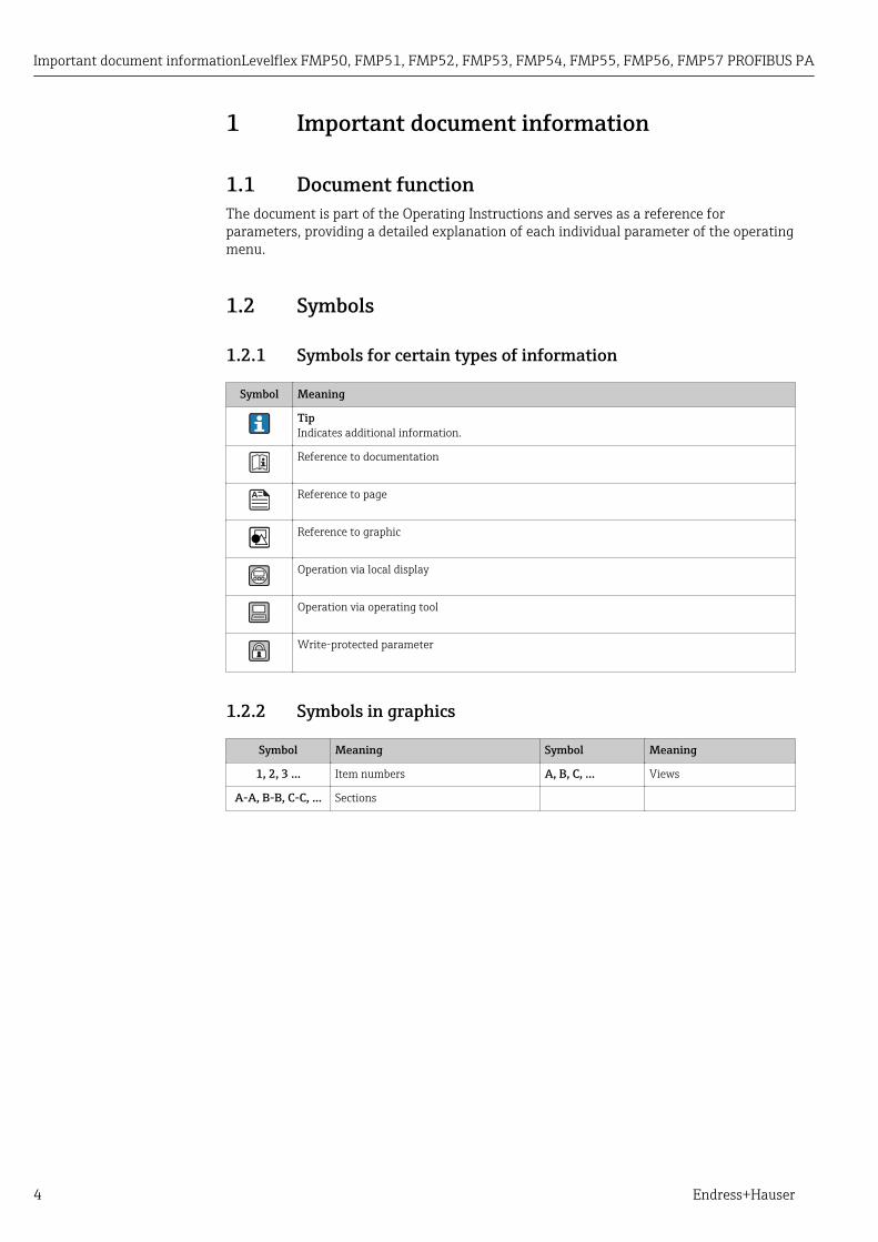
1.2.1 Symbols for certain types of information
Symbol Meaning
TipIndicates additional information.
Reference to documentation
Reference to page
Reference to graphic
Operation via local display
Operation via operating tool
Write-protected parameter
1.2.2 Symbols in graphics
Symbol Meaning Symbol Meaning
1, 2, 3 ... Item numbers A, B, C, ... Views
A-A, B-B, C-C, ... Sections

Levelflex FMP50, FMP51, FMP52, FMP53, FMP54, FMP55, FMP56, FMP57 PROFIBUS PA Basic principles
Endress+Hauser 5
2 Basic principles
2.1 Time-of-Flight principleThe Levelflex uses the guided propagation and reflection of electromagnetic pulses inorder to determine the distance to a target object. The time that passes between emittingand receiving the pulses is a measurement for the distance to the object. Since the pulseshave to travel to the object and back, the distance D is the result of half of the product ofthe duration t and the velocity of propagation c:
D = Δt × c/2
From D, the level is then calculated with the help of the calibration parameters.
F
L
D
E
20 mA
100%
4 mA
0%
LN
R
A0011360
1 Calibration parameters for the time-of-flight principle
LN Length of the probeD DistanceL LevelR Reference point of the measurementE Empty calibration (= zero)F Full calibration (= span)

Basic principles Levelflex FMP50, FMP51, FMP52, FMP53, FMP54, FMP55, FMP56, FMP57 PROFIBUS PA
6 Endress+Hauser
2.2 Interface measurementInterface measurement is possible with FMP51, FMP52, FMP54 and FMP55. It canbe activated via the Operating mode parameter (→ 52).
When the high-frequency pulses hit the surface of the medium, only a percentage of thetransmission pulse is reflected. In the case of media with a low dielectric constant DC1, inparticular, the other part penetrates the medium. The pulse is reflected once more at theinterface point to a second medium with a higher dielectric constant, DC2. The distance tothe interface layer can now also be determined taking into account the delayed time-of-flight of the pulse through the upper medium.
DK1
c = c = 300 000 km/s0
C =1
DK (DC )2 2
DK DC1 1( )C0
LL
R
LI
A0011178
2 Interface measurement with the guided radar
Preconditions for an interface measurement• The dielectric constant (DC) of the upper medium must be known and constant.
Dielectric constants for many media commonly used in the industry are summarized inthe document CD00019F, which can be downloaded from the Endress+Hauser web page(www.endress.com). In addition, if the interface thickness is existing and known, the DCcan be calculated automatically via FieldCare.
• The DC of the upper medium may not be greater than 10.• The DC difference between the upper medium and lower medium must be > 10• The upper medium must have a minimum thickness of 60 mm (2.4 in).
For dielectric constants (DC values) of many media commonly used in variousindustries refer to:• the Endress+Hauser DC manual (CP01076F)• the Endress+Hauser "DC Values App" (available for Android and iOS)
Levelflex FMP50, FMP51, FMP52, FMP53, FMP54, FMP55, FMP56, FMP57 PROFIBUS PA Basic principles
Endress+Hauser 7
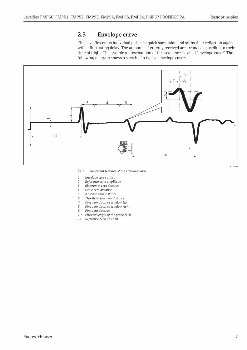
2.3 Envelope curveThe Levelflex emits individual pulses in quick succession and scans their reflection againwith a fluctuating delay. The amounts of entergy received are arranged according to theirtime of flight. The graphic represenataion of this sequence is called "envelope curve". Thefollowing diagram shows a sketch of a typical envelope curve:
11
2
3 4 5
1
10
7 8
9
6 A0016144
3 Important features of the envelope curve
1 Envelope curve offset2 Reference echo amplitude3 Electronics zero distance4 Cable zero distance5 Antenna zero distance6 Threshold fine zero distance7 Fine zero distance window left8 Fine zero distance window right9 Fine zero distance10 Physical length of the probe (LN)11 Reference echo position

Basic principles Levelflex FMP50, FMP51, FMP52, FMP53, FMP54, FMP55, FMP56, FMP57 PROFIBUS PA
8 Endress+Hauser
2.4 Mapping and subtracted curveThe mapping is used to suppress static interference signals which may be generatet byinternal tank or silo fittings. A mapping curve, representing the envelope curve of anempty tank or silo as precisely as possible, is used for the mapping.
After a mapping, the signal evaluation does not use the envelope curve but the subtractedcurve, instead:
Subtracted curve = Envelope curve - Mapping curve
A B C
41 2
3
5
6
A0017065
4 Mapping and subtracted curve
1 Interference echo2 Level echo3 End-of-probe echo4 Envelope curve5 Mapping curve6 Subtracted curveA Internal area (Z distances)B Level areaC End-of-probe area (EOP)
2.5 Echo trackingLevelflex uses an echo tracking algorithm. This means, echoes in subsequent envelopecurves are not evaluated independently but are considered to be a sequence of movingechos. To do so, each echo is surrounded by a window of a certain width and the echo issearched for within this window in the next envelope curve. If an echo of this type isfound, it is allocated to the "track" of the previous echo. Each track can be assigned aspecific meaning (level echo track, interface echo track, end-of-probe echo track, multipleecho track).
For a given installation, these tracks are in a well-defined relationship to each other. Thisrelationship is recorded during the measuruement such that later on reliable measuringvalues can be obtained even if the echo is temporarily lost or if the device is temporarilyswitched off.
For details on the echo tracking refer to: → 146.

Levelflex FMP50, FMP51, FMP52, FMP53, FMP54, FMP55, FMP56, FMP57 PROFIBUS PA Basic principles
Endress+Hauser 9
2.6 Capacitance measurement (only for FMP55)In the case of FMP55, the guided radar can be combined with a capacitance measurement.The capaciatance measurement can be used to increase the reliability of the guided radaror to obtain interface values even if the interface echo is lost.
For details on the combination of guided radar and capacitance measurement refer to:→ 155
Capacitance measurement is only possible if the electrical conductivity of the two mediafulfills the following conditions:• Conductivity of the upper medium: < 1 μS/cm• Conductivity of the lower medium: > 100 μS/cm

Overview of the operating menu Levelflex FMP50, FMP51, FMP52, FMP53, FMP54, FMP55, FMP56, FMP57 PROFIBUS PA
10 Endress+Hauser
3 Overview of the operating menu• The following table lists all parameters the "Expert" menu may contain. The page
number refers to where a description of the parameter can be found.• Depending on the device version and parametrization some parameters will not be
available in a given situation. For details on the conditions refer to the "Prerequisite"category in the description of the respective parameter.
• The representation essentially corresponds to the menu seen when using anoperating tool (e.g. FieldCare). On the local display there may be minor differencesin the menu structure. Details are mentioned in the description of the respectivesubmenu.
Navigation Expert
Expert
Direct access (0106) → 29
Locking status (0004) → 29
Access status display (0091) → 30
Access status tooling (0005) → 30
Enter access code (0003) → 31
‣ System → 32
‣ Display → 33
Language (0104) → 34
Format display (0098) → 34
Value 1 to 4 display (0107–1 to 4) → 36
Decimal places 1 to 4 (0095–1 to 4) → 36
Display interval (0096) → 37
Display damping (0094) → 37
Header (0097) → 37
Header text (0112) → 38
Separator (0101) → 38
Number format (0099) → 38
Decimal places menu (0573) → 39

Levelflex FMP50, FMP51, FMP52, FMP53, FMP54, FMP55, FMP56, FMP57 PROFIBUS PAOverview of the operating menu
Endress+Hauser 11
Contrast display (0105) → 39
Backlight (0111) → 39
Access status display (0091) → 40
‣ Configuration backup display → 42
Operating time (0652) → 43
Last backup (0102) → 43
Configuration management (0100) → 43
Backup state (0121) → 44
Comparison result (0103) → 44
‣ Administration → 46
Define access code (0093) → 47
Confirm access code → 49
Activate SW option (0029) → 47
Device reset (0000) → 47
‣ Sensor → 50
Distance unit (0551) → 52
Temperature unit (0557) → 52
Operating mode (1046) → 52
Tank type (1175) → 53
Tube diameter (1117) → 53
Bin type (1176) → 53
Process property (1081) → 54
Advanced process conditions (1177) → 55
Application parameter (1126) → 56

Overview of the operating menu Levelflex FMP50, FMP51, FMP52, FMP53, FMP54, FMP55, FMP56, FMP57 PROFIBUS PA
12 Endress+Hauser
‣ Medium → 57
Medium group (1208) → 58
Medium type (1049) → 58
Medium property (1165) → 59
DC value lower medium (1154) → 59
DC value (1201) → 60
Calculated DC value (1118) → 61
‣ Level → 63
Distance offset (2309) → 64
Empty calibration (2343) → 65
Full calibration (2308) → 66
Level unit (0576) → 67
Level limit mode (2314) → 68
High limit (2312) → 69
Low limit (2313) → 69
Level correction (2325) → 69
Output mode (2317) → 70
Level (2319) → 70
Level linearized (2318) → 72
Interface (2352) → 72
Interface linearized (2382) → 72
Thickness upper layer (2330) → 73
‣ Linearization → 75
Linearization type (2339) → 77
Unit after linearization (2340) → 78

Levelflex FMP50, FMP51, FMP52, FMP53, FMP54, FMP55, FMP56, FMP57 PROFIBUS PAOverview of the operating menu
Endress+Hauser 13
Free text (2341) → 79
Level linearized (2318) → 79
Interface linearized (2382) → 80
Maximum value (2315) → 80
Diameter (2342) → 80
Intermediate height (2310) → 81
Table mode (2303) → 81
Table number (2370) → 82
Level (2383) → 83
Level (2389) → 83
Customer value (2384) → 83
Activate table (2304) → 83
‣ Information → 85
Signal quality (1047) → 86
Absolute echo amplitude (1127) → 86
Relative echo amplitude (1089) → 87
Absolute interface amplitude (1129) → 88
Relative interface amplitude (1090) → 88
Absolute EOP amplitude (1128) → 89
Found echoes (1068) → 89
Used calculation (1115) → 90
Tank trace state (1206) → 91
Measurement frequency (1180) → 91
Electronic temperature (1062) → 91

Overview of the operating menu Levelflex FMP50, FMP51, FMP52, FMP53, FMP54, FMP55, FMP56, FMP57 PROFIBUS PA
14 Endress+Hauser
‣ Sensor properties → 93
Probe grounded (1222) → 94
Present probe length (1078) → 94
Confirm probe length (1080) → 94
Sensor module (1101) → 95
‣ Distance → 97
Distance (1124) → 98
Interface distance (1067) → 99
Dead time (1199) → 100
Integration time (1092) → 101
Blocking distance (1144) → 102
‣ Gas phase compensation → 110
GPC mode (1034) → 111
External pressure selector (1073) → 111
External pressure (1233) → 112
Gas phase compensation factor (1209) → 112
Present reference distance (1076) → 112
Reference distance (1033) → 113
Reference echo threshold (1168) → 113
Const. GPC factor (1217) → 113
‣ Sensor diagnostics → 116
Broken probe detection (1032) → 117
Start self check (1133) → 117
Result self check (1134) → 117
Noise of signal (1105) → 118
Levelflex FMP50, FMP51, FMP52, FMP53, FMP54, FMP55, FMP56, FMP57 PROFIBUS PAOverview of the operating menu
Endress+Hauser 15
‣ Safety settings → 123
Output echo lost (2307) → 124
Value echo lost (2316) → 124
Diagnostics echo lost (1401) → 125
Status echo lost (1416) → 125
Ramp at echo lost (2323) → 126
Delay time echo lost (1193) → 126
Safety distance (1093) → 127
In safety distance (1018) → 127
Diagnostic in safety distance (1415) → 127
Status in safety distance (1417) → 128
Acknowledge alarm (1130) → 128
‣ Envelope curve → 131
Envelope curve (1207) → 131
‣ Mapping → 135
Distance (1124) → 98
Interface distance (1067) → 99
Confirm distance (1045) → 138
Present mapping (1182) → 139
Mapping end point (1022) → 139
Record map (1069) → 140
‣ EOP evaluation → 142
EOP search mode (1026) → 143
EOP shift (1027) → 143

Overview of the operating menu Levelflex FMP50, FMP51, FMP52, FMP53, FMP54, FMP55, FMP56, FMP57 PROFIBUS PA
16 Endress+Hauser
DC value (1201) → 144
Calculated DC value (1118) → 145
‣ Echo tracking → 149
Evaluation mode (1112) → 150
History reset (1145) → 150
History learning control (1074) → 151
History learning (1094) → 151
‣ Interface → 160
Tank level (1111) → 161
Interface property (1107) → 161
Interface criterion (1184) → 163
Measured capacitance (1066) → 163
Build-up ratio (1210) → 163
Build-up thres. (1211) → 163
Empty capacitance (1122) → 164
‣ Output → 165
‣ Switch output → 166
Switch output function (0481) → 167
Assign diagnostic behavior (0482) → 167
Assign limit (0483) → 168
Switch-on value (0466) → 168
Switch-off value (0464) → 169
Assign status (0485) → 170
Switch-on delay (0467) → 170
Switch-off delay (0465) → 171

Levelflex FMP50, FMP51, FMP52, FMP53, FMP54, FMP55, FMP56, FMP57 PROFIBUS PAOverview of the operating menu
Endress+Hauser 17
Failure mode (0486) → 171
Switch status (0461) → 171
Invert output signal (0470) → 171
‣ Communication → 173
‣ PROFIBUS PA configuration → 174
Address mode (1468) → 175
Device address (1462) → 176
Ident number selector (1461) → 176
‣ PROFIBUS PA info → 177
Status PROFIBUS Master Config (1465) → 178
PROFIBUS ident number (1471) → 178
Profile version (1463) → 178
CRC Count OK (1469) → 178
CRC Count Failed (1470) → 178
Number of good between badtelegrams (1467)
→ 179
Base current (1466) → 179
Terminal voltage 1 (0662) → 179
‣ Physical block → 180
Device tag (1496) → 181
Static revision (1495) → 181
Strategy (1494) → 181
Alert key (1473) → 182
Target mode (1497) → 182
Mode block actual (1472) → 182
Overview of the operating menu Levelflex FMP50, FMP51, FMP52, FMP53, FMP54, FMP55, FMP56, FMP57 PROFIBUS PA
18 Endress+Hauser
Mode block permitted (1493) → 182
Mode block normal (1492) → 183
Alarm summary (1474) → 183
Software revision (1478) → 183
Hardware revision (1479) → 183
Manufacturer ID (1502) → 183
Device ID (1480) → 184
Serial number (1481) → 184
Diagnostics (1482) → 184
Diagnostics mask (1484) → 184
Device certification (1486) → 185
Factory reset (1488) → 185
Descriptor (1489) → 185
Device message (1490) → 186
Device install date (1491) → 186
Ident number selector (1461) → 186
Hardware lock (1499) → 186
Feature supported (1477) → 187
Feature enabled (1476) → 187
Condensed status diagnostic (1500) → 187
‣ Analog input 1 to 6 → 189
Tag description (1562–1 to 6) → 191
Static revision (1560–1 to 6) → 191
Strategy (1559–1 to 6) → 191
Alert key (1522–1 to 6) → 191

Levelflex FMP50, FMP51, FMP52, FMP53, FMP54, FMP55, FMP56, FMP57 PROFIBUS PAOverview of the operating menu
Endress+Hauser 19
Target mode (1563–1 to 6) → 192
Mode block actual (1521–1 to 6) → 192
Mode block permitted (1553–1 to 6) → 192
Mode block normal (1546–1 to 6) → 192
Alarm summary (1537–1 to 6) → 193
Batch ID (1533–1 to 6) → 193
Batch operation (1534–1 to 6) → 193
Batch phase (1535–1 to 6) → 193
Batch Recipe Unit Procedure(1536–1 to 6)
→ 194
Out value (1552–1 to 6) → 194
Out status (1564–1 to 6) → 194
Out status HEX (1549–1 to 6) → 195
PV scale lower range (1554–1 to 6) → 195
PV scale upper range (1555–1 to 6) → 195
Out scale lower range (1548–1 to 6) → 196
Out scale upper range (1551–1 to 6) → 196
Lin type (1523–1 to 6) → 196
Channel (1561–1 to 6) → 196
Out unit (1550–1 to 6) → 197
Out decimal point (1547–1 to 6) → 197
Out unit text (1532–1 to 6) → 198
PV filter time (1524–1 to 6) → 198
Fail safe type (1525–1 to 6) → 198
Fail safe value (1526–1 to 6) → 199
Overview of the operating menu Levelflex FMP50, FMP51, FMP52, FMP53, FMP54, FMP55, FMP56, FMP57 PROFIBUS PA
20 Endress+Hauser
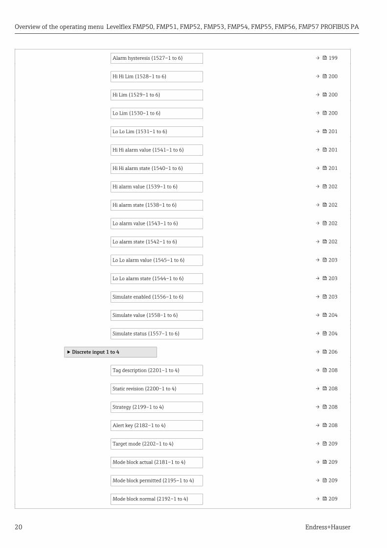
Alarm hysteresis (1527–1 to 6) → 199
Hi Hi Lim (1528–1 to 6) → 200
Hi Lim (1529–1 to 6) → 200
Lo Lim (1530–1 to 6) → 200
Lo Lo Lim (1531–1 to 6) → 201
Hi Hi alarm value (1541–1 to 6) → 201
Hi Hi alarm state (1540–1 to 6) → 201
Hi alarm value (1539–1 to 6) → 202
Hi alarm state (1538–1 to 6) → 202
Lo alarm value (1543–1 to 6) → 202
Lo alarm state (1542–1 to 6) → 202
Lo Lo alarm value (1545–1 to 6) → 203
Lo Lo alarm state (1544–1 to 6) → 203
Simulate enabled (1556–1 to 6) → 203
Simulate value (1558–1 to 6) → 204
Simulate status (1557–1 to 6) → 204
‣ Discrete input 1 to 4 → 206
Tag description (2201–1 to 4) → 208
Static revision (2200–1 to 4) → 208
Strategy (2199–1 to 4) → 208
Alert key (2182–1 to 4) → 208
Target mode (2202–1 to 4) → 209
Mode block actual (2181–1 to 4) → 209
Mode block permitted (2195–1 to 4) → 209
Mode block normal (2192–1 to 4) → 209

Levelflex FMP50, FMP51, FMP52, FMP53, FMP54, FMP55, FMP56, FMP57 PROFIBUS PAOverview of the operating menu
Endress+Hauser 21
Alarm summary (2191–1 to 4) → 210
Batch ID (2183–1 to 4) → 210
Batch operation (2184–1 to 4) → 210
Batch phase (2185–1 to 4) → 210
Batch Recipe Unit Procedure(2186–1 to 4)
→ 211
Out value (2194–1 to 4) → 211
Out status (2203–1 to 4) → 211
Out status HEX (2193–1 to 4) → 212
Channel (2187–1 to 4) → 212
Invert (2188–1 to 4) → 212
Fail safe type (2189–1 to 4) → 213
Fail safe value (2190–1 to 4) → 213
Simulate enabled (2196–1 to 4) → 213
Simulate value (2198–1 to 4) → 214
Simulate status (2197–1 to 4) → 214
‣ Analog output 1 to 4 → 217
Tag description (1667–1 to 4) → 219
Static revision (1666–1 to 4) → 219
Strategy (1665–1 to 4) → 219
Alert key (1632–1 to 4) → 219
Target mode (1668–1 to 4) → 220
Mode block actual (1631–1 to 4) → 220
Mode block permitted (1648–1 to 4) → 220
Mode block normal (1643–1 to 4) → 220

Overview of the operating menu Levelflex FMP50, FMP51, FMP52, FMP53, FMP54, FMP55, FMP56, FMP57 PROFIBUS PA
22 Endress+Hauser
Alarm summary (1642–1 to 4) → 221
Batch ID (1633–1 to 4) → 221
Batch operation (1639–1 to 4) → 221
Batch phase (1640–1 to 4) → 222
Batch Recipe Unit Procedure(1641–1 to 4)
→ 222
Set point value (1661–1 to 4) → 222
Set point status (1660–1 to 4) → 222
PV scale lower range (1651–1 to 4) → 223
PV scale upper range (1652–1 to 4) → 223
Readback value (1659–1 to 4) → 223
Readback status (1658–1 to 4) → 223
RCAS in value (1655–1 to 4) → 224
RCAS in status (1654–1 to 4) → 224
Input channel (1670–1 to 4) → 224
Output channel (1671–1 to 4) → 224
Fail safe time (1635–1 to 4) → 225
Fail safe type (1636–1 to 4) → 225
Fail safe value (1637–1 to 4) → 225
RCAS out value (1657–1 to 4) → 226
RCAS out status (1656–1 to 4) → 226
Position value (1650–1 to 4) → 226
Position status (1649–1 to 4) → 226
Setpoint deviation (1653–1 to 4) → 227
Simulate enabled (1662–1 to 4) → 227

Levelflex FMP50, FMP51, FMP52, FMP53, FMP54, FMP55, FMP56, FMP57 PROFIBUS PAOverview of the operating menu
Endress+Hauser 23
Simulate value (1664–1 to 4) → 227
Simulate status (1663–1 to 4) → 227
Increase close (1638–1 to 4) → 228
Out value (1647–1 to 4) → 228
Out status (1669–1 to 4) → 228
Out status HEX (1645–1 to 4) → 229
Out scale upper range (1646–1 to 4) → 229
Out scale lower range (1644–1 to 4) → 229
‣ Discrete output 1 to 4 → 231
Tag description (1721–1 to 4) → 233
Static revision (1720–1 to 4) → 233
Strategy (1719–1 to 4) → 233
Alert key (1694–1 to 4) → 233
Target mode (1722–1 to 4) → 234
Mode block actual (1691–1 to 4) → 234
Mode block permitted (1705–1 to 4) → 234
Mode block normal (1702–1 to 4) → 234
Alarm summary (1701–1 to 4) → 235
Batch ID (1695–1 to 4) → 235
Batch operation (1698–1 to 4) → 235
Batch phase (1699–1 to 4) → 236
Batch Recipe Unit Procedure(1700–1 to 4)
→ 236
Set point value (1715–1 to 4) → 236
Set point status (1714–1 to 4) → 236

Overview of the operating menu Levelflex FMP50, FMP51, FMP52, FMP53, FMP54, FMP55, FMP56, FMP57 PROFIBUS PA
24 Endress+Hauser
Out value (1704–1 to 4) → 237
Out status (1723–1 to 4) → 237
Out status HEX (1703–1 to 4) → 237
Readback value (1713–1 to 4) → 238
Readback status (1712–1 to 4) → 238
RCAS in value (1707–1 to 4) → 238
RCAS in status (1706–1 to 4) → 238
Input channel (1724–1 to 4) → 239
Output channel (1725–1 to 4) → 239
Invert (1692–1 to 4) → 239
Fail safe time (1697–1 to 4) → 240
Fail safe type (1696–1 to 4) → 240
Fail safe value (1693–1 to 4) → 240
RCAS out value (1711–1 to 4) → 241
RCAS out status (1708–1 to 4) → 241
Simulate enabled (1716–1 to 4) → 241
Simulate value (1718–1 to 4) → 241
Simulate status (1717–1 to 4) → 242
‣ Diagnostics → 243
Actual diagnostics (0691) → 245
Timestamp (0667) → 245
Previous diagnostics (0690) → 245
Timestamp (0672) → 246
Operating time from restart (0653) → 246
Operating time (0652) → 246

Levelflex FMP50, FMP51, FMP52, FMP53, FMP54, FMP55, FMP56, FMP57 PROFIBUS PAOverview of the operating menu
Endress+Hauser 25
‣ Diagnostic list → 247
Diagnostics 1 to 5 (0692–1 to 5) → 248
Timestamp 1 to 5 (0683–1 to 5) → 248
‣ Event logbook → 249
Filter options (0705) → 250
‣ Device information → 252
Device tag (0011) → 253
Serial number (0009) → 253
Firmware version (0010) → 253
Device name (0013) → 253
Order code (0008) → 254
Extended order code 1 to 3(0023–1 to 3)
→ 254
ENP version (0012) → 254
‣ Data logging → 255
Assign channel 1 to 4 (0851–1 to 4) → 256
Logging interval (0856) → 257
Clear logging data (0855) → 257
‣ Min/max values → 259
Max. level value (2357) → 260
Time max. level (2385) → 260
Min. level value (2358) → 260
Time min. level (2386) → 260
Max. draining speed (2320) → 260
Max. filling speed (2360) → 261

Overview of the operating menu Levelflex FMP50, FMP51, FMP52, FMP53, FMP54, FMP55, FMP56, FMP57 PROFIBUS PA
26 Endress+Hauser
Reset min./max. (2324) → 261
Max. interface value (2361) → 261
Time max. interface (2388) → 261
Min. interface value (2362) → 262
Time min. interface (2387) → 262
I max. drain speed (2363) → 262
I max. fill speed (2359) → 262
Max. electronics temperature (1031) → 262
Time max. electronics temperature(1204)
→ 263
Min. electronics temperature (1040) → 263
Time min. electronics temperature(1205)
→ 263
Reset min./max. temp. (1173) → 263
‣ Simulation → 265
Assign measurement variable (2328) → 266
Value process variable (2329) → 266
Switch output simulation (0462) → 266
Switch status (0463) → 267
Simulation device alarm (0654) → 267
‣ Device check → 268
Start device check (1013) → 269
Result device check (1014) → 269
Last check time (1203) → 269
Level signal (1016) → 270

Levelflex FMP50, FMP51, FMP52, FMP53, FMP54, FMP55, FMP56, FMP57 PROFIBUS PAOverview of the operating menu
Endress+Hauser 27
Launch signal (1012) → 270
Interface signal (1015) → 270
‣ Advanced diagnostics 1 to 2 → 278
Assign diagnostic signal 1 to 2(11179–1 to 2)
→ 279
Link AD 1 to 2 to (11180–1 to 2) → 279
Linking logic AD 1 to 2 (11181–1 to 2) → 280
Sample time 1 to 2 (11187–1 to 2) → 280
Calculation type 1 to 2 (11174–1 to 2) → 280
Check mode 1 to 2 (11175–1 to 2) → 281
Calculation unit 1 to 2 (11188–1 to 2) → 282
Upper limit 1 to 2 (11182–1 to 2) → 283
Lower limit 1 to 2 (11184–1 to 2) → 283
Hysteresis 1 to 2 (11178–1 to 2) → 284
Value (11172–1 to 2) → 284
Maximum value 1 to 2 (11183–1 to 2) → 284
Minimum value 1 to 2 (11185–1 to 2) → 284
Reset min./max. 1 to 2 (11186–1 to 2) → 285
Assign status signal to AD event 1 to 2(11176–1 to 2)
→ 285
Assign event behaviour 1 to 2(11177–1 to 2)
→ 285
Alarm delay 1 to 2 (11171–1 to 2) → 286
‣ Envelope diagnostics → 287
Save reference curve (1218) → 288
Time reference curve (1232) → 288

"Expert" menu Levelflex FMP50, FMP51, FMP52, FMP53, FMP54, FMP55, FMP56, FMP57 PROFIBUS PA
28 Endress+Hauser
4 "Expert" menuThe Expert menu contains all parameters of the device. It is structured according to thefunction blocks of the device.
4.1 Structure of the menu
Navigation Expert
Expert
Direct access (0106) → 29
Locking status (0004) → 29
Access status display (0091) → 30
Access status tooling (0005) → 30
Enter access code (0003) → 31
‣ System → 32
‣ Sensor → 50
‣ Output → 165
‣ Communication → 173
‣ Analog input 1 to 6 → 189
‣ Discrete input 1 to 4 → 206
‣ Analog output 1 to 4 → 217
‣ Discrete output 1 to 4 → 231
‣ Diagnostics → 243

Levelflex FMP50, FMP51, FMP52, FMP53, FMP54, FMP55, FMP56, FMP57 PROFIBUS PA "Expert" menu
Endress+Hauser 29
4.2 Description of parameters
Navigation Expert
Direct access
Navigation Expert → Direct access (0106)
Description Enter the access code of a parameter in order to access this parameter directly (i.e. withoutnavigation).
User entry 0 to 65 535
Factory setting 0
Additional information The direct access code consists of a five digit number and an optional channel code, whichspecifies an input or output channel, e.g. 00353-2• Leading zeros need not to be entered.
Example: You may enter "353" instead of "00353"• If the channel code is not entered, channel 1 is automatically selected.
Example: By entering "353" you access the following parameter: Curr.output 1 → Currentspan (0353–1)
• In order to access a different channel: Enter the direct access code with the channel code.Example: By entering "353-2" you access the following parameter: Curr.output 2→ Current span (0353–2)
In this document, the direct access code is added in brackets after the parameter namein the Navigation category.
Locking status
Navigation Expert → Locking status (0004)
Description Indicates the write protection with the highest priority that is currently active.
User interface • Hardware locked• SIL locked• WHG locked• Temporarily locked

"Expert" menu Levelflex FMP50, FMP51, FMP52, FMP53, FMP54, FMP55, FMP56, FMP57 PROFIBUS PA
30 Endress+Hauser
Additional information Meaning and priorities of the types of write protection• Hardware locked (priority 1)
The DIP switch for hardware locking is activated on the main electronics module. Thislocks write access to the parameters.
• SIL locked (priority 2)The SIL mode is activated. Writing access to the relevant parameters is denied.
• WHG locked (priority 3)The WHG mode is activated. Writing access to the relevant parameters is denied.
• Temporarily locked (priority 4)Write access to the parameters is temporarily locked on account of internal processes inprogress in the device (e.g. data upload/download, reset etc.). The parameters can bemodified as soon as the processes are complete.
On the display module, the -symbol appears in front of parameters that cannot bemodified since they are write-protected.
Access status display
Navigation Expert → Access stat.disp (0091)
Prerequsite The device has a local display.
Description Indicates access authorization to parameters via local display.
User interface • Operator• Maintenance• Service
Additional information If a symbol appears in front of a parameter, the parameter cannot be changed viathe local display with the current access authorization.
The access authorization can be changed via the Enter access code parameter(→ 31).
If additional write protection is active, this restricts the current access authorizationeven further. The write protection status can be viewed via the Locking statusparameter (→ 29).
Access status tooling
Navigation Expert → Access stat.tool (0005)
Description Indicates access authorization to parameters via operating tool (e.g. FieldCare).
User interface • Operator• Maintenance• Service

Levelflex FMP50, FMP51, FMP52, FMP53, FMP54, FMP55, FMP56, FMP57 PROFIBUS PA "Expert" menu
Endress+Hauser 31
Additional information The access authorization can be changed via the Enter access code parameter(→ 31).
If additional write protection is active, this restricts the current access authorizationeven further. The write protection status can be viewed via the Locking statusparameter (→ 29).
Enter access code
Navigation Expert → Ent. access code (0003)
Description Enter access code to disable write protection of parameters.
User entry 0 to 9 999
Additional information • For local operation, the customer-specific access code, which has been defined in theDefine access code parameter (→ 47), has to be entered.
• If an incorrect access code is entered, the user retains his current access authorization.• The write protection affects all parameters marked with the -symbol in this document.
On the local display, the -symbol in front of a parameter indicates that the parameteris write-protected.
• If no key is pressed for 10 min, or the user switches from the navigation and editingmode back to the measured value display mode, the device automatically locks the write-protected parameters after another 60 s.
Please contact your Endress+Hauser Sales Center if you lose your access code.

"Expert" menu Levelflex FMP50, FMP51, FMP52, FMP53, FMP54, FMP55, FMP56, FMP57 PROFIBUS PA
32 Endress+Hauser
4.3 "System" submenuThe System submenu contains all general parameters which affect neither themeasurement nor the measured value communication.
4.3.1 Structure of the submenu
Navigation Expert → System
‣ System
‣ Display → 33
‣ Configuration backup display → 42
‣ Administration → 46

Levelflex FMP50, FMP51, FMP52, FMP53, FMP54, FMP55, FMP56, FMP57 PROFIBUS PA "Expert" menu
Endress+Hauser 33
4.3.2 "Display" submenuThe Display submenu is used to configure the representation of measured values on thelocal display module. Up to four measured values can be allocated to the local displaymodule. Additionally, display characteristics such as the format of numbers, the associatedtexts or the display contrast can be configured.
This submenu is only visible if a display module is connected to the device.
Structure of the submenu
Navigation Expert → System → Display
‣ Display
Language → 34
Format display → 34
Value 1 to 4 display → 36
Decimal places 1 to 4 → 36
Display interval → 37
Display damping → 37
Header → 37
Header text → 38
Separator → 38
Number format → 38
Decimal places menu → 39
Contrast display → 39
Backlight → 39
Access status display → 40

"Expert" menu Levelflex FMP50, FMP51, FMP52, FMP53, FMP54, FMP55, FMP56, FMP57 PROFIBUS PA
34 Endress+Hauser
Description of parameters
Navigation Expert → System → Display
Language
Navigation Expert → System → Display → Language (0104)
Description Set display language.
Selection • English• Deutsch 1)
• Français 1)
• Español 1)
• Italiano 1)
• Nederlands 1)
• Portuguesa 1)
• Polski 1)
• русский язык (Russian) 1)
• Svenska 1)
• Türkçe 1)
• 中文 (Chinese) 1)
• 日本語 (Japanese) 1)
• 한국어 (Korean) 1)
• (1 (Arabic) الْعَرَبيّة
• Bahasa Indonesia 1)
• ภาษาไทย (Thai) 1)
• tiếng Việt (Vietnamese) 1)
• čeština (Czech) 1)
Factory setting The additional language selected in feature 500 of the product structure.If no additional language has been selected: English
Additional information The English option can be selected in every device. One additional operating language canbe selected in the product structure when ordering a device (feature 500 "AdditionalOperation Language") and will be selectable in the Language parameter.
Format display
Navigation Expert → System → Display → Format display (0098)
Description Select how measured values are shown on the display.
Selection • 1 value, max. size• 1 bargraph + 1 value• 2 values• 1 value large + 2 values• 4 values
1) Visibility depends on order options or device settings

Levelflex FMP50, FMP51, FMP52, FMP53, FMP54, FMP55, FMP56, FMP57 PROFIBUS PA "Expert" menu
Endress+Hauser 35
Factory setting 1 value, max. size
Additional information
4841.000mm1 Â
A0019963
5 "Format display" = "1 value, max. size"
93.5 %
159.0mm
1
1
Â
Â
A0019964
6 "Format display" = "1 bargraph + 1 value"
93.5%
159.0mm
1
1
Â
Â
A0019965
7 "Format display" = "2 values"
93.5%
159.0 mm
23.5 V
1 Â
1
1V
ÂÂ
A0019966
8 "Format display" = "1 value large + 2 values"
93.5 %
159.0 mm
93.5 V
26.3 °C
1 Â
1
1
1
V
Â
ÂÂ
A0019968
9 "Format display" = "4 values"
• The Value 1 to 4 display → 36 parameters specify which measured values areshown on the display and in which order.
• If more measured values are specified than the current display mode permits, thevalues alternate on the device display. The display time until the next change isconfigured in the Display interval parameter (→ 37).

"Expert" menu Levelflex FMP50, FMP51, FMP52, FMP53, FMP54, FMP55, FMP56, FMP57 PROFIBUS PA
36 Endress+Hauser
Value 1 to 4 display
Navigation Expert → System → Display → Value 1 display (0107)
Description Select the measured value that is shown on the local display.
Selection • None 2)
• Level linearized• Distance• Interface linearized• Interface distance• Thickness upper layer• Current output 1 3)
• Measured current• Current output 2• Terminal voltage• Electronic temperature• Measured capacitance• Analog output adv. diagnostics 1• Analog output adv. diagnostics 2
Factory setting For level measurements• Value 1 display: Level linearized• Value 2 display: Distance• Value 3 display: Current output 1• Value 4 display: None
For interface measurements and one current output• Value 1 display: Interface linearized• Value 2 display: Level linearized• Value 3 display: Thickness upper layer• Value 4 display: Current output 1
For interface measurements and two current outputs• Value 1 display: Interface linearized• Value 2 display: Level linearized• Value 3 display: Current output 1• Value 4 display: Current output 2
Decimal places 1 to 4
Navigation Expert → System → Display → Decimal places 1 to 4 (0095–1 to 4)
Description Select the number of decimal places for the display value.
Selection • x• x.x• x.xx• x.xxx• x.xxxx
2) can not be selected for the 'Value 1 display" parameter.3) "Visibility depends on order options or device settings"

Levelflex FMP50, FMP51, FMP52, FMP53, FMP54, FMP55, FMP56, FMP57 PROFIBUS PA "Expert" menu
Endress+Hauser 37
Factory setting x.xx
Additional information The setting does not affect the measuring or computational accuracy of the device.
Display interval
Navigation Expert → System → Display → Display interval (0096)
Description Set time measured values are shown on display if display alternates between values.
User entry 1 to 10 s
Factory setting 5 s
Additional information This parameter is only relevant if the number of selected measuring values exceeds thenumber of values the selected display format can display simultaneously.
Display damping
Navigation Expert → System → Display → Display damping (0094)
Description Define display reaction time to fluctuations in the measured value.
User entry 0.0 to 999.9 s
Factory setting 0.0 s
Header
Navigation Expert → System → Display → Header (0097)
Description Select header contents on local display.
Selection • Device tag• Free text
Factory setting Device tag
Additional information1 XXXXXXXXX
A0013375
1 Position of the header text on the display

"Expert" menu Levelflex FMP50, FMP51, FMP52, FMP53, FMP54, FMP55, FMP56, FMP57 PROFIBUS PA
38 Endress+Hauser
Meaning of the options
• Device tagIs defined in the Device tag parameter.
• Free textIs defined in the Header text parameter (→ 38).
Header text
Navigation Expert → System → Display → Header text (0112)
Prerequsite Header (→ 37) = Free text
Description Enter display header text.
Factory setting ------------
Additional information The number of characters which can be displayed depends on the characters used.
Separator
Navigation Expert → System → Display → Separator (0101)
Description Select decimal separator for displaying numerical values.
Selection • .• ,
Factory setting .
Number format
Navigation Expert → System → Display → Number format (0099)
Description Choose number format for the display.
Selection • Decimal• ft-in-1/16''
Factory setting Decimal
Additional information The ft-in-1/16'' option is only valid for distance units.
Levelflex FMP50, FMP51, FMP52, FMP53, FMP54, FMP55, FMP56, FMP57 PROFIBUS PA "Expert" menu
Endress+Hauser 39
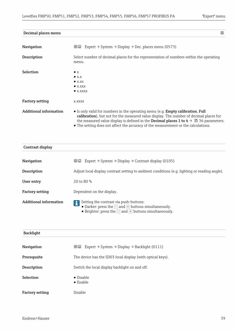
Decimal places menu
Navigation Expert → System → Display → Dec. places menu (0573)
Description Select number of decimal places for the representation of numbers within the operatingmenu.
Selection • x• x.x• x.xx• x.xxx• x.xxxx
Factory setting x.xxxx
Additional information • Is only valid for numbers in the operating menu (e.g. Empty calibration, Fullcalibration), but not for the measured value display. The number of decimal places forthe measured value display is defined in the Decimal places 1 to 4 → 36 parameters.
• The setting does not affect the accuracy of the measurement or the calculations.
Contrast display
Navigation Expert → System → Display → Contrast display (0105)
Description Adjust local display contrast setting to ambient conditions (e.g. lighting or reading angle).
User entry 20 to 80 %
Factory setting Dependent on the display.
Additional information Setting the contrast via push-buttons:• Darker: press the and E buttons simultaneously.• Brighter: press the and E buttons simultaneously.
Backlight
Navigation Expert → System → Display → Backlight (0111)
Prerequsite The device has the SD03 local display (with optical keys).
Description Switch the local display backlight on and off.
Selection • Disable• Enable
Factory setting Disable

"Expert" menu Levelflex FMP50, FMP51, FMP52, FMP53, FMP54, FMP55, FMP56, FMP57 PROFIBUS PA
40 Endress+Hauser
Additional information Meaning of the options• Disable
Switches the backlight off.• Enable
Switches the backlight on.
Regardless of the setting in this parameter the backlight may be automaticallyswitched off by the device if the supply voltage is too low.
Access status display
Navigation Expert → System → Display → Access stat.disp (0091)
Prerequsite The device has a local display.
Description Indicates access authorization to parameters via local display.
User interface • Operator• Maintenance• Service
Additional information If a symbol appears in front of a parameter, the parameter cannot be changed viathe local display with the current access authorization.
The access authorization can be changed via the Enter access code parameter(→ 31).
If additional write protection is active, this restricts the current access authorizationeven further. The write protection status can be viewed via the Locking statusparameter (→ 29).

Levelflex FMP50, FMP51, FMP52, FMP53, FMP54, FMP55, FMP56, FMP57 PROFIBUS PA "Expert" menu
Endress+Hauser 41
4.3.3 "Configuration backup display" submenuThis submenu is only visible if a display module is connected to the device.
All software configurations are initially stored in a memory module (HistoROM) in thehousing and are thus permanently connected with the device. As an additional option, thedisplay module contains a backup memory for the device configuration. The transmissionof configuration data between these two memory modules is controlled by theConfiguration management parameter (→ 43). It provides the following options:• Execute backup
Saves the current device configuration in the display module.• Restore
This option can be used to restore a configuration back into the device which haspreviously been saved in the display module.
• DuplicateIf the configuration has been saved into the display module, the module can beconnected to a different device and the configuration can be duplicated to this device.This allows to efficiently configure a number of devices in the same way.
• CompareThe comparison result indicates whether the device configuration has been changedsince the last backup.
For FMP51, FMP52, FMP54, FMP55: Configurations can only be exchanged betweendevices which are in the same operating mode (see the Operating mode parameter(→ 52)).
If an existing backup is restored to a different device using the Restore option, it mayoccur that some device functionalities are no longer available. Even a reset to thedelivery state won't restore the original state in some cases.
In order to transfer the configuration to a different device only the Duplicate optionshould be used.

"Expert" menu Levelflex FMP50, FMP51, FMP52, FMP53, FMP54, FMP55, FMP56, FMP57 PROFIBUS PA
42 Endress+Hauser
Structure of the submenu
Navigation Expert → System → Conf.backup disp
‣ Configuration backup display
Operating time → 43
Last backup → 43
Configuration management → 43
Backup state → 44
Comparison result → 44

Levelflex FMP50, FMP51, FMP52, FMP53, FMP54, FMP55, FMP56, FMP57 PROFIBUS PA "Expert" menu
Endress+Hauser 43
Description of parameters
Navigation Expert → System → Conf.backup disp
Operating time
Navigation Expert → System → Conf.backup disp → Operating time (0652)
Description Indicates how long the device has been in operation.
User interface Days (d), hours (h), minutes (m), seconds (s)
Additional information Maximum time
9 999 d ( ≈ 27 years)
Last backup
Navigation Expert → System → Conf.backup disp → Last backup (0102)
Description Indicates when the last data backup was saved to the display module.
User interface Days (d), hours (h), minutes (m), seconds (s)
Configuration management
Navigation Expert → System → Conf.backup disp → Config. managem. (0100)
Description Select action for managing the device data in the display module.
Selection • Cancel• Execute backup• Restore• Duplicate• Compare• Clear backup data
Factory setting Cancel
Additional information Meaning of the options• Cancel
No action is executed and the user exits the parameter.• Execute backup
A backup copy of the current device configuration in the HistoROM (built-in in thedevice) is saved to the display module of the device.
• RestoreThe last backup copy of the device configuration is copied from the display module to theHistoROM of the device.

"Expert" menu Levelflex FMP50, FMP51, FMP52, FMP53, FMP54, FMP55, FMP56, FMP57 PROFIBUS PA
44 Endress+Hauser
• DuplicateThe transmitter configuration is duplicated to another device using the transmitterdisplay module. The following parameters, which characterize the individual measuringpoint are not included in the transmitted configuration:Medium type
• CompareThe device configuration saved in the display module is compared to the current deviceconfiguration of the HistoROM. The result of this comparison is displayed in theComparison result parameter (→ 44).
• Clear backup dataThe backup copy of the device configuration is deleted from the display module of thedevice.
While this action is in progress, the configuration cannot be edited via the localdisplay and a message on the processing status appears on the display.
If an existing backup is restored to a different device using the Restore option, it mayoccur that some device functionalities are no longer available. In some cases even adevice reset will not restore the original status.
In order to transmit a configuration to a different device, the Duplicate option shouldalways be used.
Backup state
Navigation Expert → System → Conf.backup disp → Backup state (0121)
Description Displays which backup action is currently in progress.
Comparison result
Navigation Expert → System → Conf.backup disp → Compar. result (0103)
Description Displays the comparison result between the device and the display.
Additional information Meaning of the display options• Settings identical
The current device configuration of the HistoROM is identical to the backup copy in thedisplay module.
• Settings not identicalThe current device configuration of the HistoROM is not identical to the backup copy inthe display module.
• No backup availableThere is no backup copy of the device configuration of the HistoROM in the displaymodule.

Levelflex FMP50, FMP51, FMP52, FMP53, FMP54, FMP55, FMP56, FMP57 PROFIBUS PA "Expert" menu
Endress+Hauser 45
• Backup settings corruptThe current device configuration of the HistoROM is corrupt or not compatible with thebackup copy in the display module.
• Check not doneThe device configuration of the HistoROM has not yet been compared to the backup copyin the display module.
• Dataset incompatibleThe data sets are incompatible and can not be compared.
To start the comparison, set Configuration management (→ 43) = Compare.
If the transmitter configuration has been duplicated from a different device byConfiguration management (→ 43) = Duplicate, the new device configuration inthe HistoROM is only partially identical to the configuration stored in the displaymodule: Sensor specific properties (e.g. the mapping curve) are not duplicated. Thus,the result of the comparison will be Settings not identical.

"Expert" menu Levelflex FMP50, FMP51, FMP52, FMP53, FMP54, FMP55, FMP56, FMP57 PROFIBUS PA
46 Endress+Hauser
4.3.4 "Administration" submenuThe Administration submenu contains all parameters for the management of the device.Its structure depends on the user interface:
Structure of the submenu on the local display
Navigation Expert → System → Administration
‣ Administration
‣ Define access code → 49
Define access code → 49
Confirm access code → 49
Activate SW option → 47
Device reset → 47
Structure of the submenu in an operating tool
Navigation Expert → System → Administration
‣ Administration
Define access code → 47
Activate SW option → 47
Device reset → 47

Levelflex FMP50, FMP51, FMP52, FMP53, FMP54, FMP55, FMP56, FMP57 PROFIBUS PA "Expert" menu
Endress+Hauser 47
Description of parameters
Navigation Expert → System → Administration
Define access code
Navigation Expert → System → Administration → Def. access code (0093)
Description Define release code for write access to parameters.
User entry 0 to 9 999
Factory setting 0
Additional information If the factory setting is not changed or 0 is defined as the access code, the parametersare not write-protected and the configuration data of the device can then always bemodified. The user is logged on in the Maintenance role.
The write protection affects all parameters marked with the symbol in thisdocument. On the local display, the symbol in front of a parameter indicates thatthe parameter is write-protected.
Once the access code has been defined, write-protected parameters can only bemodified if the access code is entered in the Enter access code parameter (→ 31).
Please contact your Endress+Hauser Sales Center if you lose your access code.
For display operation: The new access code is only valid after it has been confirmed inthe Confirm access code parameter (→ 49).
Activate SW option
Navigation Expert → System → Administration → Activate SW opt. (0029)
Description Enter code to unlock specific software options.
User entry Positive integer
Factory setting 0
Device reset
Navigation Expert → System → Administration → Device reset (0000)
Description Select to which state the device is to be reset.
Selection • Cancel• To factory defaults• To delivery settings

"Expert" menu Levelflex FMP50, FMP51, FMP52, FMP53, FMP54, FMP55, FMP56, FMP57 PROFIBUS PA
48 Endress+Hauser
• Of customer settings• To transducer defaults• Restart device
Factory setting Cancel
Additional information Meaning of the options• Cancel
No action• To factory defaults
All parameters are reset to the order-code specific factory setting.• To delivery settings
All parameters are reset to the delivery setting. The delivery setting may differ from thefactory default if customer specific settings have been ordered.This option is only visible if customer specific settings have been ordered.
• Of customer settingsAll customer parameters are reset to their factory setting. Service parameters, however,remain unchanged.
• To transducer defaultsEvery measurment-related parameter is reset to its factory setting. Service parametersand communication-related parameters, however, remain unchanged.
• Restart deviceThe restart resets every parameter which is stored in the volatile memory (RAM) to thefactory setting (e.g. measured value data). The device configuration remains unchanged.
Levelflex FMP50, FMP51, FMP52, FMP53, FMP54, FMP55, FMP56, FMP57 PROFIBUS PA "Expert" menu
Endress+Hauser 49
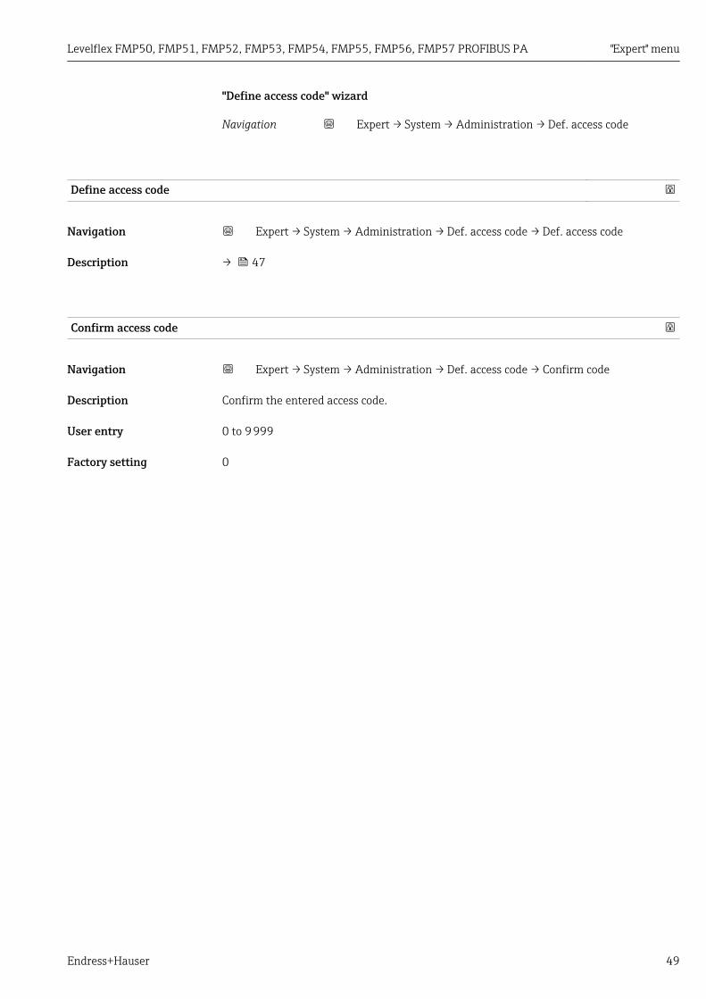
"Define access code" wizard
Navigation Expert → System → Administration → Def. access code
Define access code
Navigation Expert → System → Administration → Def. access code → Def. access code
Description → 47
Confirm access code
Navigation Expert → System → Administration → Def. access code → Confirm code
Description Confirm the entered access code.
User entry 0 to 9 999
Factory setting 0

"Expert" menu Levelflex FMP50, FMP51, FMP52, FMP53, FMP54, FMP55, FMP56, FMP57 PROFIBUS PA
50 Endress+Hauser
4.4 "Sensor" submenuThe Sensor submenu contains all parameters related to the measurement and the sensorsettings.
Navigation Expert → Sensor
4.4.1 Structure of the submenu
Navigation Expert → Sensor
‣ Sensor
Distance unit → 52
Temperature unit → 52
Operating mode → 52
Tank type → 53
Tube diameter → 53
Bin type → 53
Process property → 54
Advanced process conditions → 55
Application parameter → 56
‣ Medium → 57
‣ Level → 63
‣ Linearization → 75
‣ Information → 85
‣ Sensor properties → 93
‣ Distance → 97
‣ Gas phase compensation → 110
‣ Sensor diagnostics → 116
‣ Safety settings → 123

Levelflex FMP50, FMP51, FMP52, FMP53, FMP54, FMP55, FMP56, FMP57 PROFIBUS PA "Expert" menu
Endress+Hauser 51
‣ Envelope curve → 131
‣ Mapping → 135
‣ EOP evaluation → 142
‣ Echo tracking → 149
‣ Interface → 160

"Expert" menu Levelflex FMP50, FMP51, FMP52, FMP53, FMP54, FMP55, FMP56, FMP57 PROFIBUS PA
52 Endress+Hauser
4.4.2 Description of parameters
Navigation Expert → Sensor
Distance unit
Navigation Expert → Sensor → Distance unit (0551)
Description Select distance unit.
Selection SI units• mm• m
US units• ft• in
Factory setting m
Temperature unit
Navigation Expert → Sensor → Temperature unit (0557)
Description Select temperature unit.
Selection SI units• °C• K
US units• °F• °R
Factory setting °C
Operating mode
Navigation Expert → Sensor → Operating mode (1046)
Prerequsite The device has the "interface measurement" application package (available for FMP51,FMP52, FMP54) 4). FMP55 always contains this package.
Description Select operating mode.
Selection • Level• Interface with capacitance 5)
• Interface 5)
4) Product structure: Feature 540 "Application Package", Option EB "Interface measurement"5) Visibility depends on order options or device settings
Levelflex FMP50, FMP51, FMP52, FMP53, FMP54, FMP55, FMP56, FMP57 PROFIBUS PA "Expert" menu
Endress+Hauser 53
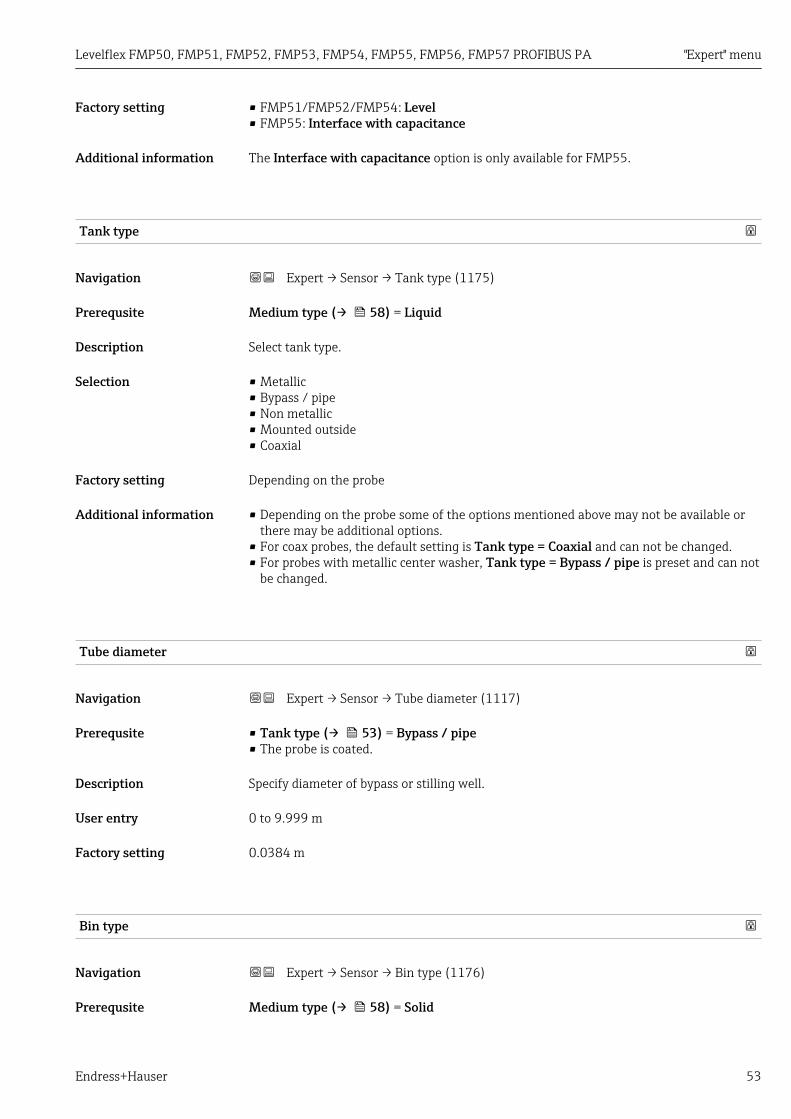
Factory setting • FMP51/FMP52/FMP54: Level• FMP55: Interface with capacitance
Additional information The Interface with capacitance option is only available for FMP55.
Tank type
Navigation Expert → Sensor → Tank type (1175)
Prerequsite Medium type (→ 58) = Liquid
Description Select tank type.
Selection • Metallic• Bypass / pipe• Non metallic• Mounted outside• Coaxial
Factory setting Depending on the probe
Additional information • Depending on the probe some of the options mentioned above may not be available orthere may be additional options.
• For coax probes, the default setting is Tank type = Coaxial and can not be changed.• For probes with metallic center washer, Tank type = Bypass / pipe is preset and can not
be changed.
Tube diameter
Navigation Expert → Sensor → Tube diameter (1117)
Prerequsite • Tank type (→ 53) = Bypass / pipe• The probe is coated.
Description Specify diameter of bypass or stilling well.
User entry 0 to 9.999 m
Factory setting 0.0384 m
Bin type
Navigation Expert → Sensor → Bin type (1176)
Prerequsite Medium type (→ 58) = Solid

"Expert" menu Levelflex FMP50, FMP51, FMP52, FMP53, FMP54, FMP55, FMP56, FMP57 PROFIBUS PA
54 Endress+Hauser
Description Specify bin type.
Selection • Concrete• Plastic wood• Metallic• Aluminium• Buffer silo (fast)• Bin / Pile• Crusher / belt• Silo• Workbench test
Factory setting Metallic
Process property
Navigation Expert → Sensor → Process property (1081)
Description Specify typical rate of level change.
Selection For "Medium type" = "Liquid"• Very fast > 10 m (400 in)/min• Fast > 1 m (40 in)/min• Standard < 1 m (40in) /min• Medium < 10 cm (4in) /min• Slow < 1 cm (0.4in) /min• No filter / test
For "Medium type" = "Solid"• Very fast > 100 m (333 ft) /h• Fast > 10 m (33 ft) /h• Standard < 10 m (33 ft) /h• Medium < 1 m (3ft) /h• Slow < 0.1 m (0.3ft) /h• No filter / test
Factory setting Standard < 1 m (40in) /min
Additional information The device adjusts the signal evaluation filters and the damping of the output signal to thetypical rate of level change defined in this parameter:
For "Operating mode" = "Level" and "Medium type" = "Liquid"
Process property Step response time / s
Very fast > 10 m (400 in)/min 5
Fast > 1 m (40 in)/min 5
Standard < 1 m (40in) /min 14
Medium < 10 cm (4in) /min 39
Slow < 1 cm (0.4in) /min 76
No filter / test < 1

Levelflex FMP50, FMP51, FMP52, FMP53, FMP54, FMP55, FMP56, FMP57 PROFIBUS PA "Expert" menu
Endress+Hauser 55
For "Operating mode" = "Level" and "Medium type" = "Solid"
Process property Step response time / s
Very fast > 100 m (333 ft) /h 37
Fast > 10 m (33 ft) /h 37
Standard < 10 m (33 ft) /h 74
Medium < 1 m (3ft) /h 146
Slow < 0.1 m (0.3ft) /h 290
No filter / test < 1
For "Operating mode" = "Interface" or "Interface with capacitance"
Process property Step response time / s
Very fast > 10 m (400 in)/min 5
Fast > 1 m (40 in)/min 5
Standard < 1 m (40in) /min 23
Medium < 10 cm (4in) /min 47
Slow < 1 cm (0.4in) /min 81
No filter / test 2.2
Other values of the step-response time (e.g. intermediate values) can be defined bythe following parameters:• Dead time (→ 100)• Integration time (→ 101)
Advanced process conditions
Navigation Expert → Sensor → Adv. conditions (1177)
Prerequsite Operating mode (→ 52) = Level
Description Specify additional process conditions (if required).
Selection • None• Oil/Water condensate• Probe near tank bottom• Build up• Foam (>5cm/0,16ft)
Factory setting None
"Expert" menu Levelflex FMP50, FMP51, FMP52, FMP53, FMP54, FMP55, FMP56, FMP57 PROFIBUS PA
56 Endress+Hauser
Additional information Meaning of the options• Oil/Water condensate (only Medium type = Liquid)
Makes sure that in the case of two-phase media only the total level is detected (example:oil/condensate application).
• Probe near tank bottom (only for Medium type = Liquid)Improves the empty detection, especially if the probe is mounted close to the tankbottom.
• Build upEnables a safe empty-detection even if the end-of-probe signal has shifted due to build-up.
• Foam (>5cm/0,16ft) (only for Medium type = Liquid)Optimizes the signal evaluation in applications with foam formation.
Application parameter
Navigation Expert → Sensor → Applicat. param. (1126)
Description Indicates whether settings depending on the application parameters (e.g. Advancedprocess conditions (→ 55), Tank type (→ 53) and Tube diameter (→ 53))have been changed after the basic setup.
User interface • Changed• Not changed
Additional information Meaning of the options• Changed
Parameters have been changed. The device is no longer in the state defined by theapplication parameters.
• Not changedThere have been no changes. The device is still in the state defined by the applicationparameters.

Levelflex FMP50, FMP51, FMP52, FMP53, FMP54, FMP55, FMP56, FMP57 PROFIBUS PA "Expert" menu
Endress+Hauser 57
4.4.3 "Medium" submenuThe Medium submenu is used to specify the relevant properties of the measured medium,especially the dielectric constant (DC).
The dielectric constant is used to calculate the threshold for the level echo and (ifapplicable) the interface echo.
For FMP51/FMP52/FMP54/FMP55: The Operating mode parameter (→ 52)determines which parameters this submenu contains.
Structure of the submenu
Navigation Expert → Sensor → Medium
‣ Medium
Medium group → 58
Medium type → 58
Medium property → 59
DC value lower medium → 59
DC value → 60
Calculated DC value → 61

"Expert" menu Levelflex FMP50, FMP51, FMP52, FMP53, FMP54, FMP55, FMP56, FMP57 PROFIBUS PA
58 Endress+Hauser
Description of parameters
Navigation Expert → Sensor → Medium
Medium group
Navigation Expert → Sensor → Medium → Medium group (1208)
Prerequsite • For FMP51/FMP52/FMP54/FMP55: Operating mode (→ 52) = Level• Medium type (→ 58) = Liquid
Description Select medium group.
Selection • Others• Water based (DC >= 4)
Factory setting Others
Additional information This parameter roughly specifies the dielectric constant (DC) of the medium. For a moredetailed definition of the DC use the Medium property parameter (→ 59).
The Medium group parameter presets the Medium property parameter (→ 59) asfollows:
Medium group Medium property (→ 59)
Others Unknown
Water based (DC >= 4) DC 4 ... 7
The Medium property parameter can be changed at a later point of time. However,when doing so, the Medium group parameter retains its value. Only the Mediumproperty parameter is relevant for the signal evaluation.
The measuring range may be reduced for small dielectric constants. For details referto the Technical Information (TI) of the respective device.
Medium type
Navigation Expert → Sensor → Medium → Medium type (1049)
Description Specify type of medium.
User interface • Liquid• Solid
Factory setting • FMP50, FMP51, FMP52, FMP53, FMP54, FMP55: Liquid• FMP56, FMP57: Solid

Levelflex FMP50, FMP51, FMP52, FMP53, FMP54, FMP55, FMP56, FMP57 PROFIBUS PA "Expert" menu
Endress+Hauser 59
Additional information The Solid option is only available for Operating mode (→ 52) = LevelThis parameter determines the value of several other parameters and stronglyinfluences the complete signal evaluation. Therefore, it is strongly recommended notto change the factory setting.
Medium property
Navigation Expert → Sensor → Medium → Medium property (1165)
Prerequsite • Operating mode (→ 52) = Level• EOP level evaluation ≠ Fix DC
Description Specify relative dielectric constant εr of the medium.
Selection • Unknown• DC 1.4 ... 1.6• DC 1.6 ... 1.9• DC 1.9 ... 2.5• DC 2.5 ... 4• DC 4 ... 7• DC 7 ... 15• DC > 15
Factory setting Dependent on Medium type (→ 58) and Medium group (→ 58).
Additional information Dependency on "Medium type" and "Medium group"
Medium type (→ 58) Medium group (→ 58) Medium property
Solid Unknown
Liquid Water based (DC >= 4) DC 4 ... 7
Others Unknown
For dielectric constants (DC values) of many media commonly used in variousindustries refer to:• the Endress+Hauser DC manual (CP01076F)• the Endress+Hauser "DC Values App" (available for Android and iOS)
For EOP level evaluation = Fix DC, the exact dielectric constant has to be enteredinto the DC value parameter. Therefore, the Medium property parameter is notavailable in this case.
DC value lower medium
Navigation Expert → Sensor → Medium → DC lower medium (1154)
Prerequsite Operating mode (→ 52) = Interface or Interface with capacitance
Description Specify the relative dielectric ocnstant εr of the lower medium.

"Expert" menu Levelflex FMP50, FMP51, FMP52, FMP53, FMP54, FMP55, FMP56, FMP57 PROFIBUS PA
60 Endress+Hauser
User entry 1 to 100
Factory setting 80.0
Additional information For dielectric constants (DC values) of many media commonly used in variousindustries refer to:• the Endress+Hauser DC manual (CP01076F)• the Endress+Hauser "DC Values App" (available for Android and iOS)
The factory setting, εr = 80, is valid for water at 20 °C (68 °F).
DC value
Navigation Expert → Sensor → Medium → DC value (1201)
Description • For level measurements:Specify dielectric constant εr.
• For interface measurements:Specify dielectric constant εr of the upper medium.
User entry Signed floating-point number
Factory setting Dependent on the following parameters:• Operating mode (→ 52)• Medium property (→ 59)• Medium type (→ 58)• Bin type (→ 53)or Tank type (→ 53)
Additional information Dependence of the factory settings on other parameters
For "Operating mode" = "Level"
Medium property(→ 59)
Medium type(→ 58)
Bin type (→ 53) or Tank type (→ 53) DC value
Unknown Solid Bin type (→ 53)• Aluminium• Plastic wood
1.9
Bin type (→ 53)• Concrete• Metallic
1.6
Liquid Tank type (→ 53)Coaxial
1.4
Any other tank type 1.9
DC 1.4 ... 1.6 Solid Bin type (→ 53)• Concrete• Aluminium• Plastic wood
1.6
Bin type (→ 53)Metallic
1.4
Liquid Tank type (→ 53)• Non metallic• Mounted outside
1.6
Any other tank type 1.4

Levelflex FMP50, FMP51, FMP52, FMP53, FMP54, FMP55, FMP56, FMP57 PROFIBUS PA "Expert" menu
Endress+Hauser 61
Medium property(→ 59)
Medium type(→ 58)
Bin type (→ 53) or Tank type (→ 53) DC value
DC 1.6 ... 1.9 1.6
DC 1.9 ... 2.5 1.9
DC 2.5 ... 4 2.5
DC 4 ... 7 4
DC 7 ... 15 7
DC > 15 15
For "Operating mode" = "Interface with capacitance" or "Interface":DC value = 1.9
As the value defines the echo threshold, it may not exceed the actual DC of themedium. Dielectric constants above DC = 15 have only a very limited influence on theecho threshold.
Calculated DC value
Navigation Expert → Sensor → Medium → Calc. DC value (1118)
Prerequsite EOP level evaluation = Automatic DC
Description • For Operating mode (→ 52) = Level:Displays the dielectric constant calculated from the level and end-of-probe signals.
• For Operating mode (→ 52) = Interface or Interface with capacitance:– For Interface property (→ 161) = Special: automatic DC:
Displays the dielectric constant of the upper medium which has been calculated fromthe level and interface signal.
– Else:Identical to DC value (→ 60).
User interface 1.0 to 100.0

"Expert" menu Levelflex FMP50, FMP51, FMP52, FMP53, FMP54, FMP55, FMP56, FMP57 PROFIBUS PA
62 Endress+Hauser
4.4.4 "Level" submenuThe Level submenu (→ 63) is used to configure the calculation of the level from themeasured distance.
D0 D L0 L
1 2 3 4 5
L
t
100%
B
0%
A
0%
100%
DL
B
A
0%
100%
E
DL0
F
D0
R
D
DD
A0016141
10 Calculation of the level from the measured distance
1 Correction of the measured distance2 Level calculation3 Level limitation4 Correction of the level5 Definition of the output value: Level (A) or Ullage (B)

Levelflex FMP50, FMP51, FMP52, FMP53, FMP54, FMP55, FMP56, FMP57 PROFIBUS PA "Expert" menu
Endress+Hauser 63
Structure of the submenu
Navigation Expert → Sensor → Level
‣ Level
Distance offset → 64
Empty calibration → 65
Full calibration → 66
Level unit → 67
Level limit mode → 68
High limit → 69
Low limit → 69
Level correction → 69
Output mode → 70
Level → 70
Level linearized → 72
Interface → 72
Interface linearized → 72
Thickness upper layer → 73

"Expert" menu Levelflex FMP50, FMP51, FMP52, FMP53, FMP54, FMP55, FMP56, FMP57 PROFIBUS PA
64 Endress+Hauser
Description of parameters
Navigation Expert → Sensor → Level
Distance offset
Navigation Expert → Sensor → Level → Distance offset (2309)
Description Specify distance offset.
User entry –200 to 200 m
Factory setting 0 m
Additional information The value specified in this parameter is added to the measured distance between thereference point of the measurement and the level echo.
• Positive values increase the distance and thus decrease the level.• Negative values decrease the distance and thus increase the level.
D0
D D0
R R
DD(<0)DD(>0)
D
A0016081
11 Effect of "Distance offset (→ 64)"
ΔD Distance offsetD0 Measured distanceD Corrected distance (is used to calculate the level)R Reference point
The value entered in this parameter changes the distance input into the level blockand thus influences the measured level.This change, however, is not taken intoaccount in the displayed distance.

Levelflex FMP50, FMP51, FMP52, FMP53, FMP54, FMP55, FMP56, FMP57 PROFIBUS PA "Expert" menu
Endress+Hauser 65
Empty calibration
Navigation Expert → Sensor → Level → Empty calibr. (2343)
Description Specify the distance E between the process connection and the minimum level (0%). Thisdefines the starting point of the measuring range.
User entry Depending on the probe
Factory setting Depending on the probe
Additional information
0%
E
A0013178
12 Empty calibration (E) for level measurements in liquids
0%
E
E
0%
A0013177
13 Empty calibration (E) for interface measurements

"Expert" menu Levelflex FMP50, FMP51, FMP52, FMP53, FMP54, FMP55, FMP56, FMP57 PROFIBUS PA
66 Endress+Hauser
E
0%
A0013180
14 Empty calibration (E) for level measurements in bulk solids.
In the case of interface measurements the Empty calibration parameter is valid forboth, the total and the interface level.
Full calibration
Navigation Expert → Sensor → Level → Full calibr. (2308)
Description Specify the distance F between the minimum level (0%) and the maximum level (100%).
User entry Depending on the probe
Factory setting Depending on the probe
Additional information
0%
F
100%
A0013186
15 Full calibration (F) for level measurements in liquids

Levelflex FMP50, FMP51, FMP52, FMP53, FMP54, FMP55, FMP56, FMP57 PROFIBUS PA "Expert" menu
Endress+Hauser 67
0%
F
F
0%
100%
100%
A0013188
16 Full calibration (F) for interface measurements
F
0%
100%
A0013191
17 Full calibration (F) for level measurements in bulk solids
In the case of interface measurements the Full calibration parameter is valid forboth, the total and the interface level.
Level unit
Navigation Expert → Sensor → Level → Level unit (0576)
Description Select level unit.
Selection SI units• %• m• mm
US units• ft• in
Factory setting %
Additional information The level unit may differ from the distance unit defined in the Distance unit parameter(→ 52):
"Expert" menu Levelflex FMP50, FMP51, FMP52, FMP53, FMP54, FMP55, FMP56, FMP57 PROFIBUS PA
68 Endress+Hauser
• The unit defined in the Distance unit parameter is used for the basic calibration (Emptycalibration (→ 65) and Full calibration (→ 66)).
• The unit defined in the Level unit parameter is used to display the (unlinearized) level.
Level limit mode
Navigation Expert → Sensor → Level → Level limit mode (2314)
Description Select the type of level limitation.
Selection • Off• Low limit• High limit• Low and High Limit
Factory setting Low limit
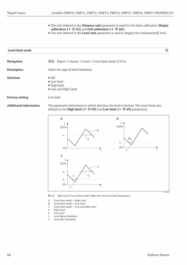
Additional information The parameter determines to which direction the level is limited. The exact limits aredefined in the High limit (→ 69) und Low limit (→ 69) parameters.
L
t
100%
A B
C
0%
a
2
1
L
t
100%
b
0%
a
1
1
22
L
t
100%
0%
b
2
1
A0016083
18 Effect of the "Level limit mode", "High limit" and "Low limit" parameters
A "Level limit mode" = "High limit"B "Level limit mode" = "Low limit"C "Level limit mode" = "Low and High Limit"a "High limit"b "Low limit"1 Level before limitation2 Level after limitation
Levelflex FMP50, FMP51, FMP52, FMP53, FMP54, FMP55, FMP56, FMP57 PROFIBUS PA "Expert" menu
Endress+Hauser 69
High limit
Navigation Expert → Sensor → Level → High limit (2312)
Prerequsite Level limit mode (→ 68) = High limit or Low and High Limit
Description Specify upper limit.
User entry Signed floating-point number
Factory setting 0 %
Additional information Levels exceeding the value specified in this parameter will be ignored. Instead, the deviceuses the maximum level specified in this parameter (for measured value transformationand output).
Low limit
Navigation Expert → Sensor → Level → Low limit (2313)
Prerequsite Level limit mode (→ 68) = Low limit or Low and High Limit
Description Specify lower level limit.
User entry –200 000.0 to 200 000.0 %
Factory setting 0.0 %
Additional information Levels falling below the value specified in this parameter will be ignored. Instead, thedevice uses the minimum level specified in this parameter (for measured valuetransformation and output).
Level correction
Navigation Expert → Sensor → Level → Level correction (2325)
Description Specify level correction (if required).
User entry –200 000.0 to 200 000.0 %
Factory setting 0.0 %
Additional information The value specified in this parameter is added to the measured level (before linearization).
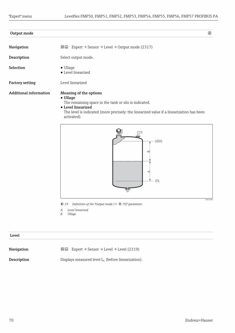
"Expert" menu Levelflex FMP50, FMP51, FMP52, FMP53, FMP54, FMP55, FMP56, FMP57 PROFIBUS PA
70 Endress+Hauser
Output mode
Navigation Expert → Sensor → Level → Output mode (2317)
Description Select output mode.
Selection • Ullage• Level linearized
Factory setting Level linearized
Additional information Meaning of the options• Ullage
The remaining space in the tank or silo is indicated.• Level linearized
The level is indicated (more precisely: the linearized value if a linearization has beenactivated).
0%
100%
BA
A0016086
19 Definition of the "Output mode (→ 70)" parameter
A Level linearizedB Ullage
Level
Navigation Expert → Sensor → Level → Level (2319)
Description Displays measured level LL (before linearization).

Levelflex FMP50, FMP51, FMP52, FMP53, FMP54, FMP55, FMP56, FMP57 PROFIBUS PA "Expert" menu
Endress+Hauser 71
Additional information
0%
LL
A0013194
20 Level in case of liquid measurements
0%
L
0%
L
LL
A0013195
21 Level in case of interface measurements
0%
LL
A0013196
22 Level in case of bulk solid measurements
• The unit is defined in the Level unit parameter (→ 67).• In case of interface measurements, this parameter always refers to the total level.

"Expert" menu Levelflex FMP50, FMP51, FMP52, FMP53, FMP54, FMP55, FMP56, FMP57 PROFIBUS PA
72 Endress+Hauser
Level linearized
Navigation Expert → Sensor → Level → Level linearized (2318)
Description Displays linearized level.
Additional information • The unit is defined by the Unit after linearization parameter → 78.• For interface measurements, this parameter always refers to the total level.
Interface
Navigation Expert → Sensor → Level → Interface (2352)
Prerequsite Operating mode (→ 52) = Interface or Interface with capacitance
Description Displays the measured interface level LI (before linearization).
Additional information
0% 0%
LI LI
A0013197
The unit is defined in the Level unit parameter (→ 67).
Interface linearized
Navigation Expert → Sensor → Level → Interf. lineariz (2382)
Prerequsite Operating mode (→ 52) = Interface or Interface with capacitance
Description Displays the linearized interface height.
Additional information The unit is defined in the Unit after linearization parameter → 78.

Levelflex FMP50, FMP51, FMP52, FMP53, FMP54, FMP55, FMP56, FMP57 PROFIBUS PA "Expert" menu
Endress+Hauser 73
Thickness upper layer
Navigation Expert → Sensor → Level → Thickn.upp.layer (2330)
Prerequsite Operating mode (→ 52) = Interface or Interface with capacitance
Description Displays the upper interface thickness (UP).
Additional information
UP
UP
A0013313
UP Thickness upper layer
The unit is defined by the Unit after linearization parameter → 78.

"Expert" menu Levelflex FMP50, FMP51, FMP52, FMP53, FMP54, FMP55, FMP56, FMP57 PROFIBUS PA
74 Endress+Hauser
4.4.5 "Linearization" submenu
0%
100%L
L
L
L
L
L
L
L2
L1
L‘1L‘2
L‘
L‘
L‘
L‘
L‘
L‘
L‘
M
M
M
M
M
Hh
h
M
0%
100%
100%
100%
0%
0%
100%
0%
0%
0%
100%
100%
B
A
C
D
E
F
G
H
2
1L
I
L‘
I‘
d
d
A0016084
23 Linearization: Transformation of the level and (if relevant) the interface height into a volume or weight;the transformation is dependent on the shape of the vessel.
1 Selection of linearization type and unit2 Configuration of the linearizationA Linearization type (→ 77) = NoneB Linearization type (→ 77) = LinearC Linearization type (→ 77) = TableD Linearization type (→ 77) = Pyramid bottomE Linearization type (→ 77) = Conical bottomF Linearization type (→ 77) = Angled bottomG Linearization type (→ 77) = Horizontal cylinderH Linearization type (→ 77) = SphereI For "Operating mode (→ 52)" = "Interface" or "Interface with capacitance": Interface before linearization
(measured in distance units)I' For "Operating mode (→ 52)" = "Interface" or "Interface with capacitance": Interface after linearization
(corresponds to volume or weight)L Level before linearization (measured in distance units)L' Level linearized (→ 72) (corresponds to volume or weight)M Maximum value (→ 80)d Diameter (→ 80)h Intermediate height (→ 81)

Levelflex FMP50, FMP51, FMP52, FMP53, FMP54, FMP55, FMP56, FMP57 PROFIBUS PA "Expert" menu
Endress+Hauser 75
Structure of the submenu on the local display
Navigation Expert → Sensor → Linearization
‣ Linearization
Linearization type → 77
Unit after linearization → 78
Free text → 79
Maximum value → 80
Diameter → 80
Intermediate height → 81
Table mode → 81
Activate table → 83

"Expert" menu Levelflex FMP50, FMP51, FMP52, FMP53, FMP54, FMP55, FMP56, FMP57 PROFIBUS PA
76 Endress+Hauser
Structure of the submenu in an operating tool (e.g. FieldCare)
Navigation Expert → Sensor → Linearization
‣ Linearization
Linearization type → 77
Unit after linearization → 78
Free text → 79
Level linearized → 79
Interface linearized → 80
Maximum value → 80
Diameter → 80
Intermediate height → 81
Table mode → 81
Table number → 82
Level → 83
Level → 83
Customer value → 83
Activate table → 83

Levelflex FMP50, FMP51, FMP52, FMP53, FMP54, FMP55, FMP56, FMP57 PROFIBUS PA "Expert" menu
Endress+Hauser 77
Description of parameters
Navigation Expert → Sensor → Linearization
Linearization type
Navigation Expert → Sensor → Linearization → Lineariz. type (2339)
Description Select linearization type.
Selection • None• Linear• Table• Pyramid bottom• Conical bottom• Angled bottom• Horizontal cylinder• Sphere
Factory setting None
Additional information
0%
100%
0%
100%
100%
0%
100%
0%
0%
100%
A B
C/D E
F/G
A0021476
24 Linearization types
A NoneB TableC Pyramid bottomD Conical bottomE Angled bottomF SphereG Horizontal cylinder

"Expert" menu Levelflex FMP50, FMP51, FMP52, FMP53, FMP54, FMP55, FMP56, FMP57 PROFIBUS PA
78 Endress+Hauser
Meaning of the options• None
The level is transmitted in the level unit without linearization.• Linear
The output value (volume/weight) is directly proportional to the level L. This is valid, forexample, for vertical cylinders. The following additional parameters have to be specified:– Unit after linearization (→ 78)– Maximum value (→ 80): Maximum volume or weight
• TableThe relationship between the measured level L and the output value (volume/weight) isgiven by a linearization table consisting of up to 32 pairs of values "level - volume" or"level - weight", respectively. The following additional parameters have to be specified:– Unit after linearization (→ 78)– Table mode (→ 81)– For each table point: Level (→ 83)– For each table point: Customer value (→ 83)– Activate table (→ 83)
• Pyramid bottomThe output value corresponds to the volume or weight in a silo with pyramid bottom.The following additional parameters have to be specified:– Unit after linearization (→ 78)– Maximum value (→ 80): Maximum volume or weight– Intermediate height (→ 81): The height of the pyramid
• Conical bottomThe output value corresponds to the volume or weight in a tank with conical bottom. Thefollowing additional parameters have to be specified:– Unit after linearization (→ 78)– Maximum value (→ 80): Maximum volume or weight– Intermediate height (→ 81): The height of the conical part of the tank
• Angled bottomThe output value corresponds to the volume or weight in a silo with an angled bottom.The following additional parameters have to be specified:– Unit after linearization (→ 78)– Maximum value (→ 80): Maximum volume or weight– Intermediate height (→ 81): Height of the angled bottom
• Horizontal cylinderThe output value corresponds to the volume or weight in a horizontal cylinder. Thefollowing additional parameters have to be specified:– Unit after linearization (→ 78)– Maximum value (→ 80): Maximum volume or weight– Diameter (→ 80)
• SphereThe output value corresponds to the volume or weight in a spherical tank. The followingadditional parameters have to be specified:– Unit after linearization (→ 78)– Maximum value (→ 80): Maximum volume or weight– Diameter (→ 80)
Unit after linearization
Navigation Expert → Sensor → Linearization → Unit lineariz. (2340)
Prerequsite Linearization type (→ 77) ≠ None
Description Select unit of the lineaized value.

Levelflex FMP50, FMP51, FMP52, FMP53, FMP54, FMP55, FMP56, FMP57 PROFIBUS PA "Expert" menu
Endress+Hauser 79
Selection SI units• STon• t• kg• cm³• dm³• m³• hl• l• %
US units• lb• UsGal• ft³
Imperial unitsimpGal
Custom-specific unitsFree text
Factory setting %
Additional information The selected unit is only used to be indicated on the display. The measured value is nottransformed according to the selected unit.
It is also possible to configure a distance-to-distance linearization, i.e. atransformation from the level unit to a different distance unit. To do so, select theLinear linearization mode. In order to define the new level unit, select the Free textoption in the Unit after linearization parameter and enter the required unit into theFree text parameter (→ 79).
Free text
Navigation Expert → Sensor → Linearization → Free text (2341)
Prerequsite Unit after linearization (→ 78) = Free text
Description Enter unit symbol.
User entry Up to 32 alphanumerical characters (letters, numbers, special characters)
Factory setting Free text
Level linearized
Navigation Expert → Sensor → Linearization → Level linearized (2318)
Description Displays linearized level.
Additional information • The unit is defined by the Unit after linearization parameter → 78.• For interface measurements, this parameter always refers to the total level.

"Expert" menu Levelflex FMP50, FMP51, FMP52, FMP53, FMP54, FMP55, FMP56, FMP57 PROFIBUS PA
80 Endress+Hauser
Interface linearized
Navigation Expert → Sensor → Linearization → Interf. lineariz (2382)
Prerequsite Operating mode (→ 52) = Interface or Interface with capacitance
Description Displays the linearized interface height.
Additional information The unit is defined in the Unit after linearization parameter → 78.
Maximum value
Navigation Expert → Sensor → Linearization → Maximum value (2315)
Prerequsite Linearization type (→ 77) has one of the following values:• Linear• Pyramid bottom• Conical bottom• Angled bottom• Horizontal cylinder• Sphere
Description Specify the maximum content of the vessel (100%) measured in the units afterlinearization.
User entry –50 000.0 to 50 000.0 %
Factory setting 100.0 %
Diameter
Navigation Expert → Sensor → Linearization → Diameter (2342)
Prerequsite Linearization type (→ 77) has one of the following values:• Horizontal cylinder• Sphere
Description Specify tank diameter.
User entry 0 to 9 999.999 m
Factory setting 2 m
Additional information The unit is defined in the Distance unit parameter (→ 52).

Levelflex FMP50, FMP51, FMP52, FMP53, FMP54, FMP55, FMP56, FMP57 PROFIBUS PA "Expert" menu
Endress+Hauser 81
Intermediate height
Navigation Expert → Sensor → Linearization → Intermed. height (2310)
Prerequsite Linearization type (→ 77) has one of the following values:• Pyramid bottom• Conical bottom• Angled bottom
Description Specify intermediate height H.
User entry 0 to 200 m
Factory setting 0 m
Additional information
0%
H
A0013264
H Intermediate height
The unit is defined in the Distance unit parameter (→ 52).
Table mode
Navigation Expert → Sensor → Linearization → Table mode (2303)
Prerequsite Linearization type (→ 77) = Table
Description Select editing mode of the linearization table.
Selection • Manual• Semiautomatic 6)
• Clear table• Sort table
Factory setting Manual
6) Visibility depends on order options or device settings

"Expert" menu Levelflex FMP50, FMP51, FMP52, FMP53, FMP54, FMP55, FMP56, FMP57 PROFIBUS PA
82 Endress+Hauser
Additional information Meaning of the options• Manual
The level and the associated linearized value are entered manually for each linearizationpoint.
• SemiautomaticThe level is measured by the device for each linearization point. The associatedlinearized value is entered manually.
• Clear tableDeletes the existing linearization table.
• Sort tableRearranges the linerization points into an ascending order.
Conditions the linearization table must meet:• The table may consist of up to 32 pairs of values "Level - Linearized Value".• The table must be monotonic (monotonically increasing or decreasing).• The first linearization point must refer to the minimum level.• The last linearization point must refer to the maximum level.
Before entering a linearization table, the values for Empty calibration (→ 65) andFull calibration (→ 66) must be set correctly.
If values of the table need to be changed after the full or empty calibration have beenchanged, a correct evaluation is only ensured if the existing table is deleted and thecomplete table is entered again. To do so delete the existing table (Table mode(→ 81) = Clear table). Then enter a new table.
How to enter the table• Via FieldCare
The table points can be entered via the Table number (→ 82), Level (→ 83)and Customer value (→ 83) parameters. As an alternative, the graphic table editormay be used: Device Operation → Device Functions → Additional Functions →Linearization (Online/Offline)
• Via local displaySelect the Edit table submenu to call up the graphic table editor. The table is displayedand can be edited line by line.
The factory setting for the level unit is "%". If you want to enter the linearization tablein physical units, you must select the appropriate unit in the Level unit parameter(→ 67) beforehand.
Table number
Navigation Expert → Sensor → Linearization → Table number (2370)
Prerequsite Linearization type (→ 77) = Table
Description Select table point you are going to enter or change.
User entry 1 to 32
Factory setting 1

Levelflex FMP50, FMP51, FMP52, FMP53, FMP54, FMP55, FMP56, FMP57 PROFIBUS PA "Expert" menu
Endress+Hauser 83
Level (Manual)
Navigation Expert → Sensor → Linearization → Level (2383)
Prerequsite • Linearization type (→ 77) = Table• Table mode (→ 81) = Manual
Description Enter level value of the table point (value before linearization).
User entry Signed floating-point number
Factory setting 0 %
Level (Semiautomatic)
Navigation Expert → Sensor → Linearization → Level (2389)
Prerequsite • Linearization type (→ 77) = Table• Table mode (→ 81) = Semiautomatic
Description Displays measured level (value before linearization). This value is transmitted to the table.
Customer value
Navigation Expert → Sensor → Linearization → Customer value (2384)
Prerequsite Linearization type (→ 77) = Table
Description Enter linearized value for the table point.
User entry Signed floating-point number
Factory setting 0 %
Activate table
Navigation Expert → Sensor → Linearization → Activate table (2304)
Prerequsite Linearization type (→ 77) = Table
Description Activate (enable) or deactivate (disable) the linearization table.
Selection • Disable• Enable

"Expert" menu Levelflex FMP50, FMP51, FMP52, FMP53, FMP54, FMP55, FMP56, FMP57 PROFIBUS PA
84 Endress+Hauser
Factory setting Disable
Additional information Meaning of the options• Disable
The measured level is not linearized.If Linearization type (→ 77) = Table at the same time, the device issues errormessage F435.
• EnableThe measured level is linearized according to the table.
When editing the table, the Activate table parameter is automatically reset toDisable and must be reset to Enable after the table has been entered.

Levelflex FMP50, FMP51, FMP52, FMP53, FMP54, FMP55, FMP56, FMP57 PROFIBUS PA "Expert" menu
Endress+Hauser 85
4.4.6 "Information" submenuThe Information submenu comprises all display parameters which give information aboutthe current state of the measurement.
Structure of the submenu
Navigation Expert → Sensor → Information
‣ Information
Signal quality → 86
Absolute echo amplitude → 86
Relative echo amplitude → 87
Absolute interface amplitude → 88
Relative interface amplitude → 88
Absolute EOP amplitude → 89
Found echoes → 89
Used calculation → 90
Tank trace state → 91
Measurement frequency → 91
Electronic temperature → 91

"Expert" menu Levelflex FMP50, FMP51, FMP52, FMP53, FMP54, FMP55, FMP56, FMP57 PROFIBUS PA
86 Endress+Hauser
Description of parameters
Navigation Expert → Sensor → Information
Signal quality
Navigation Expert → Sensor → Information → Signal quality (1047)
Description Displays the signal quality of the evaluated echo.
Additional information Meaning of the display options• Strong
The evaluated echo exceeds the threshold by at least 10 mV.• Medium
The evaluated echo exceeds the threshold by at least 5 mV.• Weak
The evaluated echo exceeds the threshold by less than 5 mV.• No signal
The device does not find a usable echo.
The signal quality indicated in this parameter always refers to the currently evaluatedecho: either the level/interface echo 7) or the end-of-probe echo. To differentiate betweenthese two, the quality of the end-of-probe echo is always displayed in brackets.
In case of a lost echo (Signal quality = No signal) the device generates the followingerror message:• F941, for Output echo lost (→ 124) = Alarm.• S941, if another option has been selected in Output echo lost (→ 124).
Absolute echo amplitude
Navigation Expert → Sensor → Information → Abs. echo ampl. (1127)
Description Displays the absolute amplitude of the level echo in the subtracted curve.
7) Of these two echos the one with the lower quality is indicated.

Levelflex FMP50, FMP51, FMP52, FMP53, FMP54, FMP55, FMP56, FMP57 PROFIBUS PA "Expert" menu
Endress+Hauser 87
Additional information
A0018378
1 Absolute echo amplitude in the envelope curve as measured from the 0mV line
Relative echo amplitude
Navigation Expert → Sensor → Information → Relat.echo ampl. (1089)
Description Displays the relative amplitude of the level echo in the subtracted curve. The relativeamplitude is the difference between the level echo and the echo threshold.

"Expert" menu Levelflex FMP50, FMP51, FMP52, FMP53, FMP54, FMP55, FMP56, FMP57 PROFIBUS PA
88 Endress+Hauser
Additional information
A0018377
1 The relative echo amplitude is the difference between the amplitude in the envelope curve (blue) and the echothreshold (green).
In the envelope curve display of FieldCare, the absolute echo amplitude is indicatedinstead of the relative amplitude (see the number on the top right of the echo peak inthe example).
Absolute interface amplitude
Navigation Expert → Sensor → Information → Abs.interf.ampl. (1129)
Prerequsite Operating mode (→ 52) = Interface or Interface with capacitance
Description Displays the absolute amplitude of the interface echo in the subtracted curve.
Relative interface amplitude
Navigation Expert → Sensor → Information → Rel.interf.ampl. (1090)
Prerequsite Operating mode (→ 52) = Interface or Interface with capacitance
Description Displays the relative amplitude of the interface echo in the subtracted curve.

Levelflex FMP50, FMP51, FMP52, FMP53, FMP54, FMP55, FMP56, FMP57 PROFIBUS PA "Expert" menu
Endress+Hauser 89
Absolute EOP amplitude
Navigation Expert → Sensor → Information → Abs. EOP ampl. (1128)
Description Displays the absolute amplitude of the end-of-probe signal in the subtracted curve.
Additional information
A0018375
1 Absolute EOP amplitude (example for an insulated end-of-probe)
Polarity of the end-of-probe signal• For probe ends which are freely suspended in the medium or insulated against the tank,
the end-of-probe signal is negative.• For probe ends which are grounded to the tank potential, the end-of-probe signal is
positive.
To ensure correct evaluation of the end-of-probe signal, its polarity must be specifiedin the EOP search mode parameter (→ 143).
Found echoes
Navigation Expert → Sensor → Information → Found echoes (1068)
Description Indicates which echoes have been found.

"Expert" menu Levelflex FMP50, FMP51, FMP52, FMP53, FMP54, FMP55, FMP56, FMP57 PROFIBUS PA
90 Endress+Hauser
User interface • None• Level• Interface• EOP• Level and interface• Level and EOP• Interface and EOP• Level, interface and EOP• EOP• EOP (TT)• EOP (LN)• Level and EOP• Multiple echo (TT)• Level and interface with capa.• Level with capa. and interface
Used calculation
Navigation Expert → Sensor → Information → Used calculation (1115)
Description Indicates which echoes are used for the calculation of the measured value.
Additional information Meaning of the options• None
The measured value is not calculated (e.g. due to a lost echo)• Level
The level is calculated from the direct level echo.• EOP
The level is calculated from the end-of-probe signal (EOP).• EOP (TT)
The level is calculated from the end-of-probe signal (EOP) taking into account the tanktable (TT).
• Multiple echo (TT)The level is calculated from the multiple echo, taking into account the tank table (TT).
• EOP (LN)An empty tank is detected from the end-of-probe signal (EOP) in the interface mode.
• Level and EOPThe level is calculated from the direct level echo. Its plausibility is checked by the end-of-probe signal (EOP). This situation may occur if the device is in the interface mode andthe tank contains only one medium.
• InterfaceThe interface height is calculated from the direct interface echo. This situation mayoccur if Tank level (→ 161) = Fully flooded.
• Measured capacitance (only for FMP55)The level is calculated from the measured capacitance without taking into account anyechoes.
• Level and interfaceThe level is calculated from the direct level echo. The interface height is calculated fromthe direct interface echo.
• Level and interface with capa.The level is calculated from the direct level echo. The interface height is calculated fromthe measured capacitance.

Levelflex FMP50, FMP51, FMP52, FMP53, FMP54, FMP55, FMP56, FMP57 PROFIBUS PA "Expert" menu
Endress+Hauser 91
Tank trace state
Navigation Expert → Sensor → Information → Tank trace state (1206)
Description Indicates the current state of the tank trace.
Additional information Meaning of the options• Not active
A valid tank trace is not available.• EOP (TT)
A valid EOP tank trace is available.• Multiple echo (TT)
A valid multiple echo tank trace is available.• EOP + Multiple echo (TT)
A valid EOP and multiple echo tank trace are available.
Measurement frequency
Navigation Expert → Sensor → Information → Measurm. freq. (1180)
Description Displays the current measurement frequency (number of pulses per second).
Additional information The measurement frequency is dependent on the length of the probe. Refer to theTechnical Information (TI) of the respective device for details.
Electronic temperature
Navigation Expert → Sensor → Information → Electronic temp. (1062)
Description Displays the current temperature of the electronics.
Additional information The unit is defined in the Temperature unit parameter (→ 52).

"Expert" menu Levelflex FMP50, FMP51, FMP52, FMP53, FMP54, FMP55, FMP56, FMP57 PROFIBUS PA
92 Endress+Hauser
4.4.7 "Sensor properties" submenuThe Sensor properties submenu comprises all parameters which describe themeasurement-related properties of the probe and the envelope curve.
Probe length correctionFor the signal evaluation it is essential that the Levelflex allocates the end-of-probe signalcorrectly. To ensure this one can manually enter the actual length of the probe or one canperform a probe length correctionn several times until the displayed length of the probematches the actual length of the probe (LN). To do so one needs the following parameters:
• Present probe length (→ 94)• Confirm probe length (→ 94)
When operating via the local display module, the Confirm probe length (→ 94)and Present probe length (→ 94) parameters are comprised in the Probelength correction sequence.

Levelflex FMP50, FMP51, FMP52, FMP53, FMP54, FMP55, FMP56, FMP57 PROFIBUS PA "Expert" menu
Endress+Hauser 93
Structure of the submenu
Navigation Expert → Sensor → Sensor prop.
‣ Sensor properties
Probe grounded → 94
Present probe length → 94
Confirm probe length → 94
Sensor module → 95
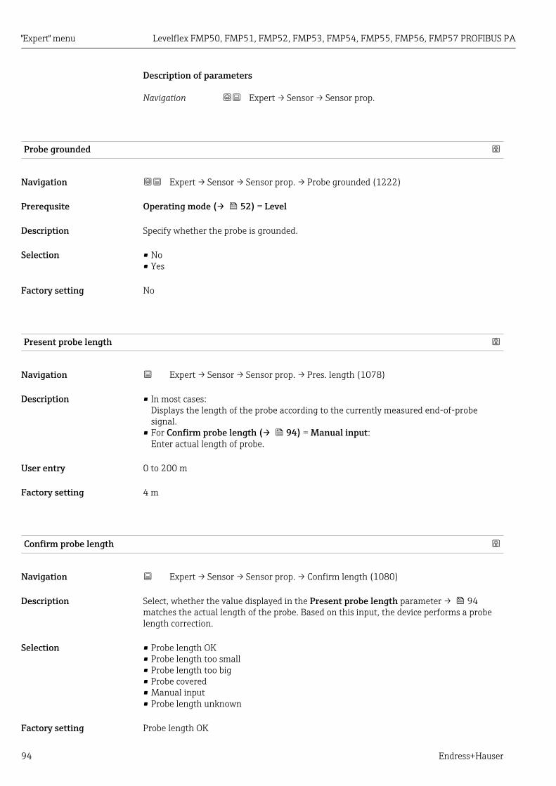
"Expert" menu Levelflex FMP50, FMP51, FMP52, FMP53, FMP54, FMP55, FMP56, FMP57 PROFIBUS PA
94 Endress+Hauser
Description of parameters
Navigation Expert → Sensor → Sensor prop.
Probe grounded
Navigation Expert → Sensor → Sensor prop. → Probe grounded (1222)
Prerequsite Operating mode (→ 52) = Level
Description Specify whether the probe is grounded.
Selection • No• Yes
Factory setting No
Present probe length
Navigation Expert → Sensor → Sensor prop. → Pres. length (1078)
Description • In most cases:Displays the length of the probe according to the currently measured end-of-probesignal.
• For Confirm probe length (→ 94) = Manual input:Enter actual length of probe.
User entry 0 to 200 m
Factory setting 4 m
Confirm probe length
Navigation Expert → Sensor → Sensor prop. → Confirm length (1080)
Description Select, whether the value displayed in the Present probe length parameter → 94matches the actual length of the probe. Based on this input, the device performs a probelength correction.
Selection • Probe length OK• Probe length too small• Probe length too big• Probe covered• Manual input• Probe length unknown
Factory setting Probe length OK
Levelflex FMP50, FMP51, FMP52, FMP53, FMP54, FMP55, FMP56, FMP57 PROFIBUS PA "Expert" menu
Endress+Hauser 95
Additional information Meaning of the options• Probe length OK
To be selected if the indicated length is correct. An adjustment is not required. Thedevice quits the sequence.
• Probe length too smallTo be selected if the displayed length is smaller than the actual length of the probe. Adifferent end of probe signal is allocated and the newly calculated length is displayed inthe Present probe length parameter → 94. This procedure has to be repeated untilthe displayed value matches the actual length of the probe.
• Probe length too bigTo be selected if the displayed length is bigger than the actual length of the probe. Adifferent end of probe signal is allocated and the newly calculated length is indicated inthe Present probe length parameter → 94. This procedure has to be repeated untilthe displayed value matches the actual length of the probe.
• Probe coveredTo be selected if the probe is (partially or completely) covered. A probe length correctionis impossible in this case. The device quits the sequence.
• Manual inputTo be selected if no automatic probe length correction is to be performed. Instead, theactual length of the probe must be entered manually into the Present probe lengthparameter → 94 8).
• Probe length unknownTo be selected if the acutal length of the probe is unknown. A probe length correction isimpossible in this case and the device quits the sequence..
Sensor module
Navigation Expert → Sensor → Sensor prop. → Sensor module (1101)
Description Displays the type of sensor module.
8) When operated via FieldCare, the Manual input option needs not to be selected explicitly. In FieldCare the length of the probe can always beedited.

"Expert" menu Levelflex FMP50, FMP51, FMP52, FMP53, FMP54, FMP55, FMP56, FMP57 PROFIBUS PA
96 Endress+Hauser
4.4.8 "Distance" submenuThe Distance submenu contains all parameters which control the filtering of the rawdistance D1. The resulting distance D0 is used for the subsequent calculation of the level.
D1 D0
1 2
A0016175
25 The configurable distance filters
1 Dead time (→ 100)2 Integration time (→ 101) (low pass filter)
Low pass filterThe low pass filter dampens the distance signal with a user defined integration time τ(Integration time parameter (→ 101)). After a sudden change of the level, it takesabout 5 x τ, until the new measured value is obtained.
t
D1
2
5 x t
A0016169
26 Low pass filter
1 Signal before the low pass filter2 Signal after the low pass filterτ Integration time (→ 101)

Levelflex FMP50, FMP51, FMP52, FMP53, FMP54, FMP55, FMP56, FMP57 PROFIBUS PA "Expert" menu
Endress+Hauser 97
Structure of the submenu
Navigation Expert → Sensor → Distance
‣ Distance
Distance → 98
Interface distance → 99
Dead time → 100
Integration time → 101
Blocking distance → 102

"Expert" menu Levelflex FMP50, FMP51, FMP52, FMP53, FMP54, FMP55, FMP56, FMP57 PROFIBUS PA
98 Endress+Hauser
Description of parameters
Navigation Expert → Sensor → Distance
Distance
Navigation Expert → Sensor → Distance → Distance (1124)
Description Displays the measured distance DL between the reference point (lower edge of the flangeor threaded connection) and the level.
Additional information
DL
A0013198
27 Distance for liquid measurements
DL
DL
A0013199
28 Distance for interface measurements

Levelflex FMP50, FMP51, FMP52, FMP53, FMP54, FMP55, FMP56, FMP57 PROFIBUS PA "Expert" menu
Endress+Hauser 99
DL
A0013201
29 Distance for bulk solid measurements
The unit is defined in the Distance unit parameter (→ 52).
Interface distance
Navigation Expert → Sensor → Distance → Interface dist. (1067)
Prerequsite Operating mode (→ 52) = Interface or Interface with capacitance
Description Displays the measured distance DI between the reference point (lower edge of flange orthreaded connection) and the interface.
Additional information
DI
DI
A0013202
The unit is defined in the Distance unit parameter (→ 52).

"Expert" menu Levelflex FMP50, FMP51, FMP52, FMP53, FMP54, FMP55, FMP56, FMP57 PROFIBUS PA
100 Endress+Hauser
Dead time
Navigation Expert → Sensor → Distance → Dead time (1199)
Description Define the dead time (in seconds).
User entry 0 to 60 s
Factory setting Dependent on the following parameters:• Medium type (→ 58)• Process property (→ 54)
Additional information Factory setting for level measurements with "Medium type" = "Liquid"
Process property (→ 54) Dead time
Fast > 1 m (40 in)/min 0 s
Standard < 1 m (40in) /min 1 s
Medium < 10 cm (4in) /min 3 s
Slow < 1 cm (0.4in) /min 6 s
No filter / test 0 s
Factory setting for level measurements with "Medium type" = "Solid"
Process property (→ 54) Dead time
Fast > 10 m (33 ft) /h 1 s
Standard < 10 m (33 ft) /h 3 s
Medium < 1 m (3ft) /h 5 s
Slow < 0.1 m (0.3ft) /h 10 s
No filter / test 0 s
Factory setting for interface measurements
Process property (→ 54) Dead time
Fast > 1 m (40 in)/min 0 s
Standard < 1 m (40in) /min 10 s
Medium < 10 cm (4in) /min 10 s
Slow < 1 cm (0.4in) /min 10 s
No filter / test 0 s
ApplicationSudden changes of the measured distance are ignored during the time span defined in thisparameter. In this way it is possible to prevent short-term interferences form disturbingthe output signal.

Levelflex FMP50, FMP51, FMP52, FMP53, FMP54, FMP55, FMP56, FMP57 PROFIBUS PA "Expert" menu
Endress+Hauser 101
t
D
2 3
1
A0016164
30 Effect of the dead time
1 Dead time2 Signal before the dead time filter3 Signal after the dead time filter
Disadvantages• The device slows down.• Fast level changes are registered with a delay.
Integration time
Navigation Expert → Sensor → Distance → Integration time (1092)
Description Define the integration time (in seconds).
User entry 0.0 to 200 000.0 s
Factory setting Dependent on the following parameters:• Medium type (→ 58)• Process property (→ 54)
Additional information Factory setting for "Medium type" = "Liquid"
Process property (→ 54) Integration time
Fast > 1 m (40 in)/min 1 s
Standard < 1 m (40in) /min 5 s
Medium < 10 cm (4in) /min 15 s
Slow < 1 cm (0.4in) /min 30 s
No filter / test 0 s
Factory setting for "Medium type" = "Solid"
Process property (→ 54) Integration time
Fast > 10 m (33 ft) /h 37 s
Standard < 10 m (33 ft) /h 74 s
Medium < 1 m (3ft) /h 145 s

"Expert" menu Levelflex FMP50, FMP51, FMP52, FMP53, FMP54, FMP55, FMP56, FMP57 PROFIBUS PA
102 Endress+Hauser
Process property (→ 54) Integration time
Slow < 0.1 m (0.3ft) /h 290 s
No filter / test < 0.8 s
Increasing the integration time results in a calmer measuring signal. However, it alsocauses a delayed reaction to level changes.
Blocking distance
Navigation Expert → Sensor → Distance → Blocking dist. (1144)
Description Specify upper blocking distance UB.
User entry 0 to 200 m
Factory setting • For coax probes: 0 mm (0 in)• For rod and rope probes up to 8 m (26 ft): 200 mm (8 in)• For rod and rope probes above 8 m (26 ft): 0.025 * Sondenlänge
Additional information No echos are evaluated within the blocking distance UB. Therefore, UB can be used tosuppress interference echos within the upper end of the probe.
UB
A0013219
31 Blocking distance (UB) for liquid measurements

Levelflex FMP50, FMP51, FMP52, FMP53, FMP54, FMP55, FMP56, FMP57 PROFIBUS PA "Expert" menu
Endress+Hauser 103
UB
A0013221
32 Blocking distance (UB) for bulk solid measurements

"Expert" menu Levelflex FMP50, FMP51, FMP52, FMP53, FMP54, FMP55, FMP56, FMP57 PROFIBUS PA
104 Endress+Hauser
4.4.9 "Gas phase compensation" submenuFor FMP51, FMP52 and FMP54: The Gas phase compensation submenu(→ 110) is only available if Operating mode (→ 52) = Level.
Einfluss der GasphaseHigh pressures reduce the propagation velocity of the measuring signals in the gas/vaporabove the fluid. This effect depends on the kind of gas/vapor and of its temperature. Thisresults in a systematic measuring error that gets bigger as the distance increases betweenthe reference point of the measurement (flange) and the product surface.
The following table illustrates this measured error for a few typical gases/vapors (withregard to distance; a positive value means that too large a distance is being measured):
Gas layer Temperature Pressure
°C °F 1 bar (14.5 psi) 10 bar (145 psi) 50 bar (725 psi) 100 bar (1 450 psi) 200 bar (2 900 psi) 400 bar (5 800 psi)
Air 20 68 0.00 % 0.22 % 1.2 % 2.4 % 4.9 % 9.5 %
200 392 –0.01 % 0.13 % 0.74 % 1.5 % 3.0 % 6.0 %
400 752 –0.02 % 0.08 % 0.52 % 1.1 % 2.1 % 4.2 %
Hydrogen 20 68 –0.01 % 0.10 % 0.61 % 1.2 % 2.5 % 4.9 %
200 392 –0.02 % 0.05 % 0.37 % 0.76 % 1.6 % 3.1 %
400 752 –0.02 % 0.03 % 0.25 % 0.53 % 1.1 % 2.2 %
Gas layer Temperature Pressure
°C °F 1 bar(14.5 psi)
2 bar(29 psi)
5 bar(72.5 psi)
10 bar(145 psi)
20 bar(290 psi)
50 bar(725 psi)
100 bar(1 450 psi)
200 bar(2 900 psi)
Water(saturated
steam)
100 212 0.26 % - - - - - - -
120 248 0.23 % 0.50 % - - - - - -
152 306 0.20 % 0.42 % 1.14 % - - - - -
180 356 0.17 % 0.37 % 0.99 % 2.10 % - - - -
212 414 0.15 % 0.32 % 0.86 % 1.79 % 3.9 % - - -
264 507 0.12 % 0.26 % 0.69 % 1.44 % 3.0 % 9.2 % - -
311 592 0.09 % 0.22 % 0.58 % 1.21 % 2.5 % 7.1 % 19.3 % -
366 691 0.07 % 0.18 % 0.49 % 1.01 % 2.1 % 5.7 % 13.2 % 76 %
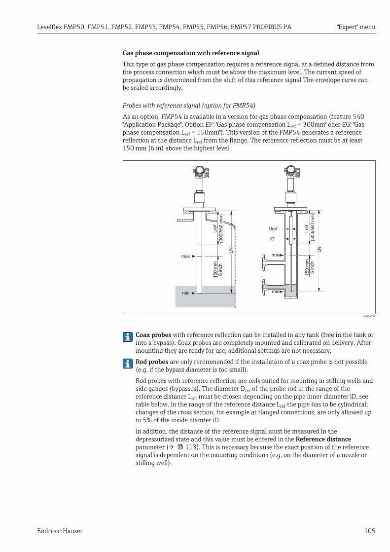
Levelflex FMP50, FMP51, FMP52, FMP53, FMP54, FMP55, FMP56, FMP57 PROFIBUS PA "Expert" menu
Endress+Hauser 105
Gas phase compensation with reference signalThis type of gas phase compensation requires a reference signal at a defined distance fromthe process connection which must be above the maximum level. The current speed ofpropagation is determined from the shift of this reference signal The envelope curve canbe scaled accordingly.
Probes with reference signal (option for FMR54)
As an option, FMP54 is available in a version for gas phase compensation (feature 540"Application Package", Option EF: "Gas phase compensation Lref = 300mm" oder EG: "Gasphase compensation Lref = 550mm"). This version of the FMP54 generates a referencereflection at the distance Lref from the flange. The reference reflection must be at least150 mm (6 in) above the highest level.
Dref
iD
max
min
150 m
m6 inch
LN
Lre
f
max
min
150 m
m6 inch
LN
Lre
f
(300/5
50 m
m)
(300/5
50 m
m)
A0014534
Coax probes with reference reflection can be installed in any tank (free in the tank orinto a bypass). Coax probes are completely mounted and calibrated on delivery. Aftermounting they are ready for use; additional settings are not necessary.
Rod probes are only recommended if the installation of a coax probe is not possible(e.g. if the bypass diameter is too small).
Rod probes with reference reflection are only suited for mounting in stilling wells andside gauges (bypasses). The diameter Dref of the probe rod in the range of thereference distance Lref must be chosen depending on the pipe inner diameter iD, seetable below. In the range of the reference distance Lref the pipe has to be cylindrical;changes of the cross section, for example at flanged connections, are only allowed upto 5% of the inside diamter iD.
In addition, the distance of the reference signal must be measured in thedepressurized state and this value must be entered in the Reference distanceparameter (→ 113). This is necessary because the exact position of the referencesignal is dependent on the mounting conditions (e.g. on the diameter of a nozzle orstilling well).

"Expert" menu Levelflex FMP50, FMP51, FMP52, FMP53, FMP54, FMP55, FMP56, FMP57 PROFIBUS PA
106 Endress+Hauser
Inner diameter iD of the stilling well/bypass Diameter Dref of the rod probe within the reference distanceLref
40 mm (1.57 in) ≤ iD < 45 mm (1.77 in) 22 mm (0.87 in)
45 mm (1.77 in) ≤ iD < 70 mm (2.76 in) 25 mm (0.98 in)
70 mm (2.76 in) ≤ iD < 100 mm (3.94 in) 30 mm (1.18 in)
Limitations for coax/rod probes
Maximum probe length LN LN ≤ 4 000 mm (157 in)
Minimum probe length LN LN > Lref + 200 mm (7.7 in)
Reference distance Lref 300 mm (11.8 in) or 550 mm (21.7 in), see feature 540 ofthe product structure
Maximum level relative to sealing surface of flange Lref + 150 mm (5.9 in)
Minimum dielectric constant of the medium DC > 7

Levelflex FMP50, FMP51, FMP52, FMP53, FMP54, FMP55, FMP56, FMP57 PROFIBUS PA "Expert" menu
Endress+Hauser 107
When can the gas phase compensation with reference signal be used?
Level measurements with high pressure for measuring ranges up to a few meters in polarmedia with a dielectric constant DC > 7 (e.g. water or ammonia), which would cause a highmeasuring error without the compensation.
The accuracy of measurement at reference conditions is the higher the larger the referencelength Lref and the samller the measuring range is:
5
10
15
20
25
30
35
40
45
0 500 1000 1500 2000 2500 3000 3500 4000
D [mm]
Delta
[mm
]
Lref = 550 mm
Lref = 300 mm
A0014535
D Distance from liquid surface to lower edge of the flangeDelta Measuring error
If there are fast pressure changes, there may be an additional error, since the measuredreference distance is filtered with the time constant of the level measurement. In addition,non-equilibrium conditions - for example due to heating - may cause density gradientswithin the medium and condensation of steam at the probe. As a result, the level readingsat different locations inside the tank may vary slightly. Caused by this applicationinfluences the measuring error may be increased by a factor up to 2 to 3.
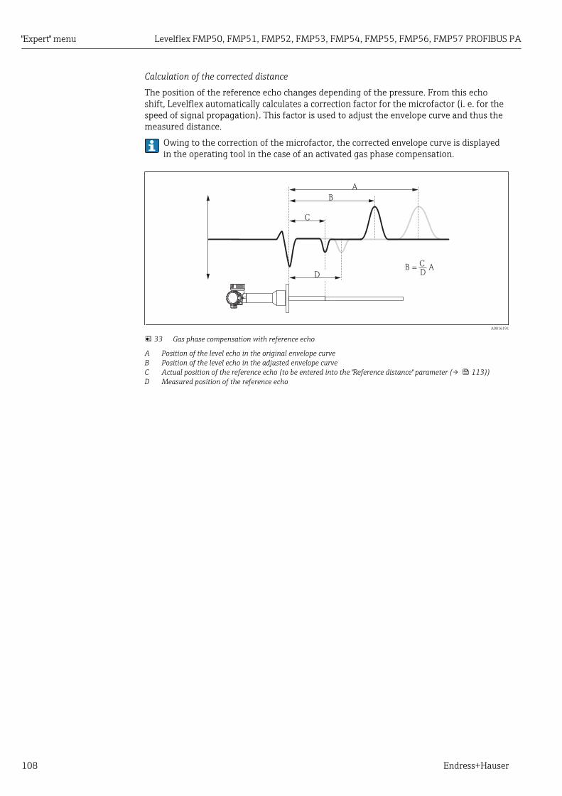
"Expert" menu Levelflex FMP50, FMP51, FMP52, FMP53, FMP54, FMP55, FMP56, FMP57 PROFIBUS PA
108 Endress+Hauser
Calculation of the corrected distance
The position of the reference echo changes depending of the pressure. From this echoshift, Levelflex automatically calculates a correction factor for the microfactor (i. e. for thespeed of signal propagation). This factor is used to adjust the envelope curve and thus themeasured distance.
Owing to the correction of the microfactor, the corrected envelope curve is displayedin the operating tool in the case of an activated gas phase compensation.
C
D
A
B
B =C
DA
A0016191
33 Gas phase compensation with reference echo
A Position of the level echo in the original envelope curveB Position of the level echo in the adjusted envelope curveC Actual position of the reference echo (to be entered into the "Reference distance" parameter (→ 113))D Measured position of the reference echo

Levelflex FMP50, FMP51, FMP52, FMP53, FMP54, FMP55, FMP56, FMP57 PROFIBUS PA "Expert" menu
Endress+Hauser 109
Constant gas phase compensation factorIf the properties of the gas phase (pressure, temperature, composition) do not change overthe time and are known, a gas phase compensation can also be performed without areference signal. Instead, a constant, user-defined correction factor is applied in this case.This factor is used to scale the envelope curve (and thus the measured echo distance).
A
B
B = FA
A0016192
34 Gas phase compensation with a constant correction factor F
A Position of the level echo in the original envelope curveB Position of the level echo in the corrected envelope curve.

"Expert" menu Levelflex FMP50, FMP51, FMP52, FMP53, FMP54, FMP55, FMP56, FMP57 PROFIBUS PA
110 Endress+Hauser
Structure of the submenu
Navigation Expert → Sensor → Gas phase comp.
‣ Gas phase compensation
GPC mode → 111
External pressure selector → 111
External pressure → 112
Gas phase compensation factor → 112
Present reference distance → 112
Reference distance → 113
Reference echo threshold → 113
Const. GPC factor → 113

Levelflex FMP50, FMP51, FMP52, FMP53, FMP54, FMP55, FMP56, FMP57 PROFIBUS PA "Expert" menu
Endress+Hauser 111
Description of parameters
Navigation Expert → Sensor → Gas phase comp.
GPC mode
Navigation Expert → Sensor → Gas phase comp. → GPC mode (1034)
Description Select gas phase compensation mode.
Selection • Off• On• Without correction• External correction 9)
• Const. GPC factor
Factory setting Off
Additional information Meaning of the options• Off
The gas phase compensation is deactivated.• On
This option can only be selected for probes with reference echo. The gas phasecompensation is calculated from the position of this reference echo. In FieldCare, thedisplayed envelope curve does already contain the correction.
• Without correctionThe correction factor is calculated from the reference echo but not applied to themeasurement. In FieldCare, the envelope curve is displayed without the correction. Thisoption is only used for diagnostic purposes and should not be selected in normalapplications.
• External correctionThe device receives the externally measured pressure through an AO block and uses ittogether with the gas phase compensation factor F to calculate the gas phasecompensation. The displayed envelope curve does already contain the correction.
• Const. GPC factorThe correction factor is a constant defined by the user. A reference echo is not needed. InFieldCare, the displayed envelope curve does already contain the correction.
External pressure selector
Navigation Expert → Sensor → Gas phase comp. → Ext. press.input (1073)
Prerequsite GPC mode (→ 111) = External correction
Description Allocate an AO block to the gas phase compensation. The externally measured pressure isread via this AO block.
9) Visibility depends on communication

"Expert" menu Levelflex FMP50, FMP51, FMP52, FMP53, FMP54, FMP55, FMP56, FMP57 PROFIBUS PA
112 Endress+Hauser
Selection • None• Analog output 1• Analog output 2• Analog output 3• Analog output 4
Factory setting None
External pressure
Navigation Expert → Sensor → Gas phase comp. → External press. (1233)
Prerequsite GPC mode (→ 111) = External correction
Description Indicates the measured pressure which is currently used for the gas phase compensation.
Gas phase compensation factor
Navigation Expert → Sensor → Gas phase comp. → Gas comp. factor (1209)
Prerequsite GPC mode (→ 111) = External correction
Description Define gas phase compensation factor F.
User entry Signed floating-point number
Factory setting 0
Additional information Suitable value for saturated steam in the temperature range 100 to 350 °C (212 to 662 °F):
F = 0.00505 / bar
Present reference distance
Navigation Expert → Sensor → Gas phase comp. → Pres. ref. dist. (1076)
Prerequsite GPC mode (→ 111) = On or Without correction
Description Displays the currently measured distance of the reference echo.

Levelflex FMP50, FMP51, FMP52, FMP53, FMP54, FMP55, FMP56, FMP57 PROFIBUS PA "Expert" menu
Endress+Hauser 113
Reference distance
Navigation Expert → Sensor → Gas phase comp. → Reference dist. (1033)
Prerequsite GPC mode (→ 111) = On or Without correction
Description Enter actual distance of the reference echo.
User entry 0 to 200 m
Factory setting According to the probe
Reference echo threshold
Navigation Expert → Sensor → Gas phase comp. → Ref. echo thresh (1168)
Prerequsite GPC mode (→ 111) = On or Without correction
Description Define threshold for the reference echo.
User entry –999.0 to 999.0 mV
Factory setting –80 mV
Additional information • Only echoes exceeding the defined threshold are accepted as reference echo.• Positive reference echoes are not suited for Levelflex as they might be mistaken for the
level echo.
Const. GPC factor
Navigation Expert → Sensor → Gas phase comp. → Const.GPC factor (1217)
Prerequsite GPC mode (→ 111) = Const. GPC factor
Description Specify constant correction factor for the measured distance.
User entry 0.5 to 1.5
Factory setting 1

"Expert" menu Levelflex FMP50, FMP51, FMP52, FMP53, FMP54, FMP55, FMP56, FMP57 PROFIBUS PA
114 Endress+Hauser
4.4.10 "Sensor diagnostics" submenuThe Sensor diagnostics submenu comprises all parameters which contain informationabout the state of the probe and the HF cable.
Broken probe detectionIn the case of a broken probe caused by mechanical wear, a negative echo arises at thebreaking point. If the broken probe detection is active, the device looks for a signal of thistype and creates an error message if required.
The borken probe detection can only be used if an interference echo suppression(map) has been correctly recorded.

Levelflex FMP50, FMP51, FMP52, FMP53, FMP54, FMP55, FMP56, FMP57 PROFIBUS PA "Expert" menu
Endress+Hauser 115
Self checkThe Start self check (→ 117) and Result self check (→ 117) parameters are usedfor the proof-test which is required for SIL applications in regular intervals. For detailsrefer to the description of the test procedure C in the Functional Safety Manual SD00326F.
For the self check, a test signal is generated in the sensor module and fed onto the analogsignal path. The device software checks whether this test signal is within the admissibleamplitude and distance ranges. The result of the self check is displayed in the Result selfcheck parameter (→ 117).

"Expert" menu Levelflex FMP50, FMP51, FMP52, FMP53, FMP54, FMP55, FMP56, FMP57 PROFIBUS PA
116 Endress+Hauser
Structure of the submenu
Navigation Expert → Sensor → Sensor diag.
‣ Sensor diagnostics
Broken probe detection → 117
Start self check → 117
Result self check → 117
Noise of signal → 118

Levelflex FMP50, FMP51, FMP52, FMP53, FMP54, FMP55, FMP56, FMP57 PROFIBUS PA "Expert" menu
Endress+Hauser 117
Description of parameters
Navigation Expert → Sensor → Sensor diag.
Broken probe detection
Navigation Expert → Sensor → Sensor diag. → Brok.probe detec (1032)
Description Switch the broken probe detection on or off.
Selection • Off• On
Factory setting Off
Additional information If the broken probe detection is switched on: As soon as a broken probe is detected, thedevice generates ana alarm and the diagnostic message Broken probe detected.
Start self check
Navigation Expert → Sensor → Sensor diag. → Start self check (1133)
Description Start a self check of the device.
Selection • No• Yes
Factory setting No
Additional information For the self check, a test signal is generated in the sensor module and fed onto the analogsignal path. The device software checks whether this test signal is within the admissibleamplitude and distance ranges. The result of the self check is displayed in the Result selfcheck parameter (→ 117).
The self check is used for the proof-test which is required for SIL applications inregular intervals. For details refer to the description of the test procedure C in theFunctional Safety Manual SD00326F.
Result self check
Navigation Expert → Sensor → Sensor diag. → Result selfcheck (1134)
Description Displays the result of the self check.

"Expert" menu Levelflex FMP50, FMP51, FMP52, FMP53, FMP54, FMP55, FMP56, FMP57 PROFIBUS PA
118 Endress+Hauser
Additional information Meaning of the options• Ok
The self check has been passed.• Not ok
The self check failed.• Check not done
A self check has not been performed.
Noise of signal
Navigation Expert → Sensor → Sensor diag. → Noise of signal (1105)
Description Displays the noise of signal in the envelope curve

Levelflex FMP50, FMP51, FMP52, FMP53, FMP54, FMP55, FMP56, FMP57 PROFIBUS PA "Expert" menu
Endress+Hauser 119
4.4.11 "Safety settings" submenuThe Safety settings submenu contains all parameters which determnine the behavior ofthe device in critical situations such as an echo loss or an undershooting of a user definedsafety distance.
Behavior in the case of an echo lossThe bahavior in case of an echo loss is defined in the Output echo lost parameter(→ 124). Depending on the selected option, suitable values must be selected in anumber of additional parameters:
Option selected in in "Output echo lost (→ 124)" Required additional parameters
Last valid value Delay time echo lost (→ 126)
Ramp at echo lost • Ramp at echo lost (→ 126)• Delay time echo lost (→ 126)
Value echo lost • Value echo lost (→ 124)• Delay time echo lost (→ 126)
Alarm 1)
1) The alarm bahavior ist defined in the submenus "Current output" (HART) or "Analog input" (PROFIBUS PA,FOUNDATION Fieldbus).
0L
t
E
1
2 3
A0016206
35 "Output echo lost (→ 124)" = "Last valid value"
1 Echo loss2 Delay time echo lost (→ 126)3 The last valid measured value is held.

"Expert" menu Levelflex FMP50, FMP51, FMP52, FMP53, FMP54, FMP55, FMP56, FMP57 PROFIBUS PA
120 Endress+Hauser
0L
E
1
2
3
4
%
5
min
t
A0016207
36 "Output echo lost (→ 124)" = "Ramp at echo lost"
1 Echo loss2 "Delay time echo lost (→ 126)"3 For a positive ramp: The measured value is increased with a constant rate until it reaches the maximum value
(100%).4 For a negative ramp: The measured value is decreased with a constant rate until it reaches the minimum
value (0%).5 The ramp is specified as "percentage of the defined measuring span per minute".
0L
E
1
2
3
t
A0016208
37 "Output echo lost (→ 124)" = "Value echo lost"
1 Echo loss2 Delay time echo lost (→ 126)3 Value echo lost (→ 124)

Levelflex FMP50, FMP51, FMP52, FMP53, FMP54, FMP55, FMP56, FMP57 PROFIBUS PA "Expert" menu
Endress+Hauser 121
Safety distanceIn order to get a warning message if the level rises into the proximity of the upper blockingdistance, a safety distance can be defined in the Safety distance parameter (→ 127).
2
1
A0016210
38 Definition of the safety distance
1 Blocking distance (→ 102)2 Safety distance (→ 127)
The behavior of the device in case the level rises into the safety distance is defined in thefollowing parameters:
• In safety distance (→ 127)• Acknowledge alarm (→ 128)
0
L
E
S942
1
t
2
A0016211
39 "In safety distance" = "Alarm": If the safety distance is undershot, the device generates an alarm.
1 Safety distance (→ 127)2 Value defined in "Failure mode"

"Expert" menu Levelflex FMP50, FMP51, FMP52, FMP53, FMP54, FMP55, FMP56, FMP57 PROFIBUS PA
122 Endress+Hauser
0
L
E
1
t
S942
!
A0016212
40 "In safety distance" = "Warning": If the safety distance is undershot, the device continues measuring butnevertheless generates a warning.
1 Safety distance (→ 127)
0
L
E
S942
1
t
2
3
A0016213
41 "In safety distance" = "Self holding": If the safety distance is undershot, the device generates an alarm. Themeasurement is not resumed until this alarm has been acknowledged by the user.
1 Safety distance (→ 127)2 Value defined in "Failure mode"3 Acknowledge alarm (→ 128)

Levelflex FMP50, FMP51, FMP52, FMP53, FMP54, FMP55, FMP56, FMP57 PROFIBUS PA "Expert" menu
Endress+Hauser 123
Structure of the submenu
Navigation Expert → Sensor → Safety sett.
‣ Safety settings
Output echo lost → 124
Value echo lost → 124
Diagnostics echo lost → 125
Status echo lost → 125
Ramp at echo lost → 126
Delay time echo lost → 126
Safety distance → 127
In safety distance → 127
Diagnostic in safety distance → 127
Status in safety distance → 128
Acknowledge alarm → 128

"Expert" menu Levelflex FMP50, FMP51, FMP52, FMP53, FMP54, FMP55, FMP56, FMP57 PROFIBUS PA
124 Endress+Hauser
Description of parameters
Navigation Expert → Sensor → Safety sett.
Output echo lost
Navigation Expert → Sensor → Safety sett. → Output echo lost (2307)
Description Define the behavior of the output signal in case of a lost echo.
Selection • Last valid value• Ramp at echo lost• Value echo lost• Alarm
Factory setting Last valid value
Additional information Meaning of the options• Last valid value
The last valid value is kept in the case of a lost echo.• Ramp at echo lost
In the case of a lost echo the output value is continously shifted towards 0% or 100%.The slope of the ramp is defined in the Ramp at echo lost parameter (→ 126).
• Value echo lostIn the case of a lost echo the output assumes the value defined in the Value echo lostparameter (→ 124).
• AlarmIn the case of a lost echo the device generates an alarm; see the Failure mode parameter
Value echo lost
Navigation Expert → Sensor → Safety sett. → Value echo lost (2316)
Prerequsite Output echo lost (→ 124) = Value echo lost
Description Define output value in case of a lost echo.
User entry 0 to 200 000.0 %
Factory setting 0.0 %
Additional information Use the unit which has been defined for the measured value output:• without linearization: Level unit (→ 67)• with linearization: Unit after linearization (→ 78)
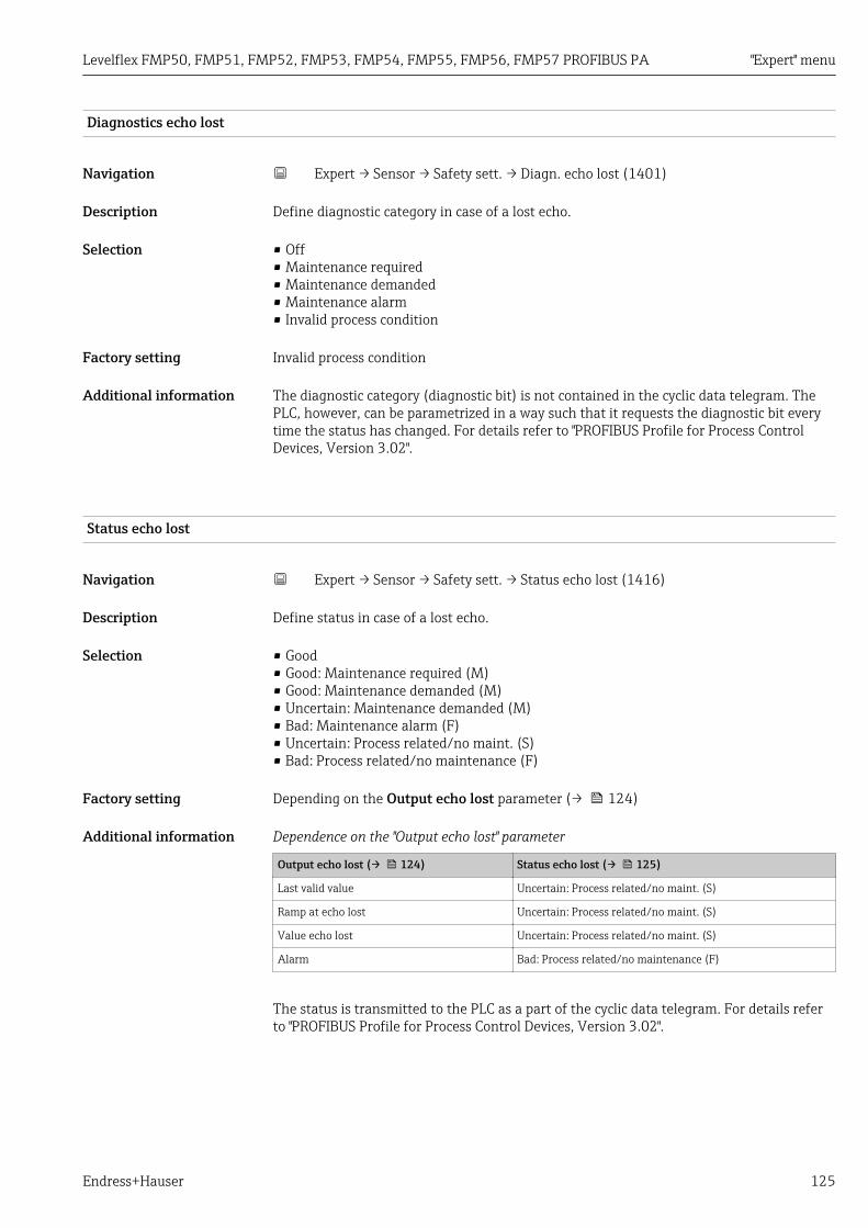
Levelflex FMP50, FMP51, FMP52, FMP53, FMP54, FMP55, FMP56, FMP57 PROFIBUS PA "Expert" menu
Endress+Hauser 125
Diagnostics echo lost
Navigation Expert → Sensor → Safety sett. → Diagn. echo lost (1401)
Description Define diagnostic category in case of a lost echo.
Selection • Off• Maintenance required• Maintenance demanded• Maintenance alarm• Invalid process condition
Factory setting Invalid process condition
Additional information The diagnostic category (diagnostic bit) is not contained in the cyclic data telegram. ThePLC, however, can be parametrized in a way such that it requests the diagnostic bit everytime the status has changed. For details refer to "PROFIBUS Profile for Process ControlDevices, Version 3.02".
Status echo lost
Navigation Expert → Sensor → Safety sett. → Status echo lost (1416)
Description Define status in case of a lost echo.
Selection • Good• Good: Maintenance required (M)• Good: Maintenance demanded (M)• Uncertain: Maintenance demanded (M)• Bad: Maintenance alarm (F)• Uncertain: Process related/no maint. (S)• Bad: Process related/no maintenance (F)
Factory setting Depending on the Output echo lost parameter (→ 124)
Additional information Dependence on the "Output echo lost" parameter
Output echo lost (→ 124) Status echo lost (→ 125)
Last valid value Uncertain: Process related/no maint. (S)
Ramp at echo lost Uncertain: Process related/no maint. (S)
Value echo lost Uncertain: Process related/no maint. (S)
Alarm Bad: Process related/no maintenance (F)
The status is transmitted to the PLC as a part of the cyclic data telegram. For details referto "PROFIBUS Profile for Process Control Devices, Version 3.02".

"Expert" menu Levelflex FMP50, FMP51, FMP52, FMP53, FMP54, FMP55, FMP56, FMP57 PROFIBUS PA
126 Endress+Hauser
Ramp at echo lost
Navigation Expert → Sensor → Safety sett. → Ramp echo lost (2323)
Prerequsite Output echo lost (→ 124) = Ramp at echo lost
Description Define the slope of the ramp in the case of a lost echo.
User entry Signed floating-point number
Factory setting 0.0 %/min
Additional information
t
min
0%
100%
A
B
C
A0013269
A Delay time echo lost (→ 126)B Ramp at echo lost (→ 126) (positive value)C Ramp at echo lost (→ 126) (negative value)
• The unit for the slope of the ramp is "percentage of the measuring range per minute" (%/min).
• For a negative slope of the ramp: The measured value is continuously decreased until itreaches 0%.
• For a positive slope of the ramp: The measured value is continuosly increased until itreaches 100%.
Delay time echo lost
Navigation Expert → Sensor → Safety sett. → Delay echo lost (1193)
Description Define the delay in the case of an echo loss.
User entry 0 to 99 999.9 s
Factory setting 60.0 s
Additional information After an echo loss, the device waits for the time specified in this parameter before reactingas specified in the Output echo lost parameter (→ 124). This helps to avoidinterruptions of the measurement by short-term interferences.

Levelflex FMP50, FMP51, FMP52, FMP53, FMP54, FMP55, FMP56, FMP57 PROFIBUS PA "Expert" menu
Endress+Hauser 127
Safety distance
Navigation Expert → Sensor → Safety sett. → Safety distance (1093)
Description Define safety distance.
User entry –200 to 200 m
Factory setting 0 m
Additional information The safety distance is measured from the reference point of the measurement (lower edgeof the flange or threaded connection). The safety distance can be used to generate awarning before the level rises into the blocking distance. The In safety distance parameter(→ 127) defines the reaction of the device if the level rises into the safety distance.
In safety distance
Navigation Expert → Sensor → Safety sett. → In safety dist. (1018)
Description Define reaction if the level rises into the safety distance.
Selection • Off• Alarm• Warning• Self holding
Factory setting Warning
Additional information Meaning of the options• Off
No reaction if the level rises into the safety distance• Alarm
The device assumes the alarm state and generates the diagnostic message In safetydistance.
• WarningThe device assumes the warning state and generates the diagnostic message In safetydistance.
• Self holdingThe device assumes the defined alarm state. Additionally, the diagnostic message Insafety distance is generated. If the level drops out of the safety distance, the alarmremains active. The measurement is continued only after a reset of the self holding viathe Acknowledge alarm parameter (→ 128).
Diagnostic in safety distance
Navigation Expert → Sensor → Safety sett. → Diag.safety dist (1415)
Description Define the diagnsotic category in case the safety distance is undershot.
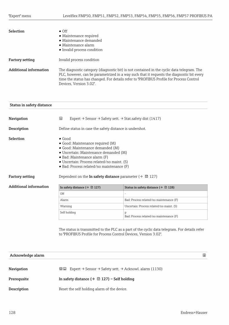
"Expert" menu Levelflex FMP50, FMP51, FMP52, FMP53, FMP54, FMP55, FMP56, FMP57 PROFIBUS PA
128 Endress+Hauser
Selection • Off• Maintenance required• Maintenance demanded• Maintenance alarm• Invalid process condition
Factory setting Invalid process condition
Additional information The diagnostic category (diagnostic bit) is not contained in the cyclic data telegram. ThePLC, however, can be parametrized in a way such that it requests the diagnostic bit everytime the status has changed. For details refer to "PROFIBUS Profile for Process ControlDevices, Version 3.02".
Status in safety distance
Navigation Expert → Sensor → Safety sett. → Stat.safety dist (1417)
Description Define status in case the safety distance is undershot.
Selection • Good• Good: Maintenance required (M)• Good: Maintenance demanded (M)• Uncertain: Maintenance demanded (M)• Bad: Maintenance alarm (F)• Uncertain: Process related/no maint. (S)• Bad: Process related/no maintenance (F)
Factory setting Dependent on the In safety distance parameter (→ 127)
Additional information In safety distance (→ 127) Status in safety distance (→ 128)
Off -
Alarm Bad: Process related/no maintenance (F)
Warning Uncertain: Process related/no maint. (S)
Self holding pBad: Process related/no maintenance (F)
The status is transmitted to the PLC as a part of the cyclic data telegram. For details referto "PROFIBUS Profile for Process Control Devices, Version 3.02".
Acknowledge alarm
Navigation Expert → Sensor → Safety sett. → Acknowl. alarm (1130)
Prerequsite In safety distance (→ 127) = Self holding
Description Reset the self holding alarm of the device.

Levelflex FMP50, FMP51, FMP52, FMP53, FMP54, FMP55, FMP56, FMP57 PROFIBUS PA "Expert" menu
Endress+Hauser 129
Selection • No• Yes
Factory setting No
Additional information Meaning of the options• No
The alarm is not rest.• Yes
The alarm is reset. The measurement is resumed.

"Expert" menu Levelflex FMP50, FMP51, FMP52, FMP53, FMP54, FMP55, FMP56, FMP57 PROFIBUS PA
130 Endress+Hauser
4.4.12 "Envelope curve" submenuThe Envelope curve submenu (→ 131) is only available on the display module(not in FieldCare). It is used to display the envelope curve on the display module.When operating via FieldCare, the envelope curve can be displayed in the envelopecurve editor (Device Operation → Device Functions → Additional Functions →Envelope Curve).

Levelflex FMP50, FMP51, FMP52, FMP53, FMP54, FMP55, FMP56, FMP57 PROFIBUS PA "Expert" menu
Endress+Hauser 131
Description of parameters
Navigation Expert → Sensor → Env. curve
Envelope curve
Navigation Expert → Sensor → Env. curve → Env. curve (1207)
Description Define which curves are included in the envelope curve display on the display module.
Selection • Envelope curve• Envelope + Map• Subtracted + Threshold• Envelope + Ref.
Factory setting Envelope curve
Additional information The display of the selected curve is called up as follows:
E
A0014279
To quit the envelope curve display, press the "+" and "-" keys simultaneously.
When operating via FieldCare, the envelope curve can be displayed in the envelopecurve editor (Device Operation → Device Functions → Additional Functions →Envelope Curve).

"Expert" menu Levelflex FMP50, FMP51, FMP52, FMP53, FMP54, FMP55, FMP56, FMP57 PROFIBUS PA
132 Endress+Hauser
4.4.13 "Mapping" submenuThe mapping is used to suppress static interference signals which may be generatet byinternal tank or silo fittings. A mapping curve, representing the envelope curve of anempty tank or silo as precisely as possible, is used for the mapping.
Mapping curve and subtracted curveAfter a mapping, the signal evaluation does not use the envelope curve but the subtractedcurve, instead:
Subtracted curve = Envelope curve - Mapping curve
A B C
41 2
3
5
6
A0017065
42 Mapping and subtracted curve
1 Interference echo2 Level echo3 End-of-probe echo4 Envelope curve5 Mapping curve6 Subtracted curveA Internal area (Z distances)B Level areaC End-of-probe area (EOP)
Static mapThe static map is typically used for rod and coax probes. It is recorded during thecommissioning. It is essential that the probe is completely uncovered when recording themap.
When recording a new static envelope curve, the previous curve is deleted.
Dynamic mapThe dynamic map is, for example, used for probes with a reference signal for gas phasecompensation. In the case of a static map this reference signal would be suppresed andwould no longer be visible in the subtracted curve.
Before the dynamic mapping curve can be used, a static map - if present - must be deleted.
The dynamic map continuously adjusts itself to the changing conditions within the vessel.An averaging width of 1 500 mm (60 in) is used for this. This prevents the dynamic mapfrom suppressing the acutal level echo.
Combined mapIf it is not possible to record the map with the probe being completely uncovered (e.g.because the vessel can not be completely emptied during the commissioning procedure), acombined map can be used instead. In this case, a static map is only recorded for the upperpart of the probe (defined by the Mapping end point parameter (→ 139)). In the

Levelflex FMP50, FMP51, FMP52, FMP53, FMP54, FMP55, FMP56, FMP57 PROFIBUS PA "Expert" menu
Endress+Hauser 133
lower part, a dynamic map is used. Both curves are connected by an interpolation area toensure a smooth transition.
-60
300 400 500 600 700 800 900 1000 1100
-40
-20
0
20
40
60
80
100
1C
B
A
2
3
A0017067
43 Combined mapping curve
1 Envelope curve2 Mapping curve3 Subtracted curveA Static areaB Transition area (interpolation)C Dynamic area
The initial mapAn initial map is stored in the device. This map is active under the following conditions:• if no static map has been recorded,• if the static map has been deactivated,• if the static map has been deleted.
The form of the initial map depends on a number of settings of the basic calibration and isdesigned to suppress typical interferences in the upper part of the probe. It can not bechanged by the user.

"Expert" menu Levelflex FMP50, FMP51, FMP52, FMP53, FMP54, FMP55, FMP56, FMP57 PROFIBUS PA
134 Endress+Hauser
Structure of the submenu on the local display
Navigation Expert → Sensor → Mapping
‣ Mapping
‣ Mapping → 135
Confirm distance → 138
Mapping end point → 139
Record map → 140
Distance → 136

Levelflex FMP50, FMP51, FMP52, FMP53, FMP54, FMP55, FMP56, FMP57 PROFIBUS PA "Expert" menu
Endress+Hauser 135
Structure of the submenu in an operating tool
Navigation Expert → Sensor → Mapping
"Mapping" submenu
‣ Mapping
Distance → 136
Interface distance → 137
Confirm distance → 138
Present mapping → 139
Mapping end point → 139
Record map → 140

"Expert" menu Levelflex FMP50, FMP51, FMP52, FMP53, FMP54, FMP55, FMP56, FMP57 PROFIBUS PA
136 Endress+Hauser
Description of parameters
Navigation Expert → Sensor → Mapping
Distance
Navigation Expert → Sensor → Mapping → Distance (1124)
Description Displays the measured distance DL between the reference point (lower edge of the flangeor threaded connection) and the level.
Additional information
DL
A0013198
44 Distance for liquid measurements
DL
DL
A0013199
45 Distance for interface measurements

Levelflex FMP50, FMP51, FMP52, FMP53, FMP54, FMP55, FMP56, FMP57 PROFIBUS PA "Expert" menu
Endress+Hauser 137
DL
A0013201
46 Distance for bulk solid measurements
The unit is defined in the Distance unit parameter (→ 52).
Interface distance
Navigation Expert → Sensor → Mapping → Interface dist. (1067)
Prerequsite Operating mode (→ 52) = Interface or Interface with capacitance
Description Displays the measured distance DI between the reference point (lower edge of flange orthreaded connection) and the interface.
Additional information
DI
DI
A0013202
The unit is defined in the Distance unit parameter (→ 52).

"Expert" menu Levelflex FMP50, FMP51, FMP52, FMP53, FMP54, FMP55, FMP56, FMP57 PROFIBUS PA
138 Endress+Hauser
Confirm distance
Navigation Expert → Sensor → Mapping → Confirm distance (1045)
Description Specify, whether the measured distance matches the real distance.
Depending on the selection the device automatically sets the range of mapping.
Selection • Manual map• Distance ok• Distance unknown• Distance too small 10)
• Distance too big 10)
• Tank empty• Delete map
Factory setting Distance unknown
Additional information Meaning of the options• Manual map
To be selected if the range of mapping is to be defined manually in the Mapping endpoint parameter (→ 139). In this case it is not necessary to confirm the distance.
• Distance okTo be selected if the measured distance matches the actual distance. The deviceperforms a mapping.
• Distance unknownTo be selected if the actual distance is unknown. A mapping can not be performed in thiscase.
• Distance too smallTo be selected if the measured distance is smaller than the actual distance. The devicesearches for the next echo and returns to the Confirm distance parameter. The distanceis recalculated and displayed. The comparison must be repeated until the displayeddistance matches the actual distance. After this, the recording of the map can be startedby selecting Distance ok.
10) Visibility depends on order options or device settings

Levelflex FMP50, FMP51, FMP52, FMP53, FMP54, FMP55, FMP56, FMP57 PROFIBUS PA "Expert" menu
Endress+Hauser 139
• Distance too big 11)
To be selected if the measured distance exceeds the actual distance. The device adjuststhe signal evaluation and returns to the Confirm distance parameter. The distance isrecalculated and displayed. The comparison must be repeated until the displayeddistance matches the actual distance. After this, the recording of the map can be startedby selecting Distance ok.
• Tank emptyTo be selected if the tank is completely empty. The device records a mapping coveringthe complete measuring range.
• Factory mapTo be selected if the present mapping curve (if one exists) is to be deleted. The devicereturns to the Confirm distance parameter and a new mapping can be recorded.
When operating via the display module, the measured distance is displayed togetherwith this parameter for reference purposes.
For interface measurements the distance always refers to the toatal level (not theinterface level).
For FMP55 with rope probes and Operating mode (→ 52) = Interface withcapacitance the mapping must be recorded with the tank being empty, and the Tankempty option must be selected. Otherwise the device can not register the correctempty capacitance.
For FMP55 with coax probes a mapping must be recorded at least in the upper part ofthe probe, as tightening the flange has an influence on the envelope curve. However,even with coax probes it is recommended to record the mapping with the tank beingcompletely empty (and selecting the Tank empty option).
If the teaching procedure with the Distance too small option or the Distance too bigoption is quit before the distance has been confirmed, a map is not recorded and theteaching procedure is reset after 60 s.
For FMP54 with gas phase compensation (product structure: feature 540 "ApplicationPackage", option EF or EG) a map must not be recorded.
Present mapping
Navigation Expert → Sensor → Mapping → Present mapping (1182)
Description Indicates up to which distance a mapping has already been recorded.
Mapping end point
Navigation Expert → Sensor → Mapping → Map. end point (1022)
Prerequsite Confirm distance (→ 138) = Manual map or Distance too small
Description Specify new end of the mapping.
User entry 0 to 200 000.0 m
11) Only available for "Expert → Sensor → Echo tracking → Evaluation mode parameter (→ 150)" = "Short time history" or "Long time history"

"Expert" menu Levelflex FMP50, FMP51, FMP52, FMP53, FMP54, FMP55, FMP56, FMP57 PROFIBUS PA
140 Endress+Hauser
Factory setting 0.1 m
Additional information This parameter defines up to which distance the new mapping is to be recorded. Thedistance is measured from the reference point, i.e. from the lower edge of the mountingflange or the threaded connection.
For reference purposes the Present mapping parameter (→ 139) is displayedtogether with this parameter. It indicates up to which distance a mapping has alreadybeen recorded.
Record map
Navigation Expert → Sensor → Mapping → Record map (1069)
Prerequsite Confirm distance (→ 138) = Manual map or Distance too small
Description Start recording of the map.
Selection • No• Record map• Delete map
Factory setting No
Additional information Meaning of the options• No
The map is not recorded.• Record map
The map is recorded. After the recording is completed, the new measured distance andthe new mapping range appear on the display. When operating via the local display,these values must be confirmed by pressing .
• Delete mapThe mapping (if one exists) is deleted and the device displays the recalculated measureddistance and the mapping range. When operating via the local display, these values mustbe confirmed by pressing .

Levelflex FMP50, FMP51, FMP52, FMP53, FMP54, FMP55, FMP56, FMP57 PROFIBUS PA "Expert" menu
Endress+Hauser 141
4.4.14 "EOP evaluation" submenuAs an alternative to evaluating the direct level signal, Levelflex can calculate the level viathe shift of the end-of-probe signal (EOP). Details on the EOP evaluation are configured inthe EOP evaluation submenu.
Shift of the end-of-probe signal (EOP)
L
A
A0017696
47 Shift of the end-of-probe signal (EOP) depending on the level
A EOP shiftL Level
When evaluating the end-of-probe signal, you make use of the fact that electromagneticpulses propagate more slowly in a medium than in air. As a consequence the end-of-probesignal moves downwards when the level is increased. By inverting this relationship onecan calculate the level L from the end-of-probe shift A:
L = A / (SQRT (DK) - 1)
Where DC is the dielectric constant of the medium.
If both, the level signal and the end-of-probe signal are known, the dielectric constant DCcan be calculated:
DK = (A/L + 1)2
The calcluated DC value is displayed in the Calculated DC value parameter (→ 61).

"Expert" menu Levelflex FMP50, FMP51, FMP52, FMP53, FMP54, FMP55, FMP56, FMP57 PROFIBUS PA
142 Endress+Hauser
Structure of the submenu
Navigation Expert → Sensor → EOP evaluation
‣ EOP evaluation
EOP search mode → 143
EOP shift → 143
DC value → 144
Calculated DC value → 145

Levelflex FMP50, FMP51, FMP52, FMP53, FMP54, FMP55, FMP56, FMP57 PROFIBUS PA "Expert" menu
Endress+Hauser 143
Description of parameters
Navigation Expert → Sensor → EOP evaluation
EOP search mode
Navigation Expert → Sensor → EOP evaluation → EOP search mode (1026)
Prerequsite Operating mode parameter (→ 52) = Level
Description Select method for the detection of the end-of-probe signal.
Selection • Empty recognition only• Negative EOP• Positive EOP• Negative EOP high resolution
Factory setting Negative EOP
Additional information Meaning of the options• Empty recognition only
Positive and negative end-of-probe signals are searched for. However, the level is notcalculated from the end-of-probe signal.– If no level signal is present and if the end-of-probe signal is within the range defined
in the EOP range upper area parameter, the level is set to 0%, which means an emptytank or silo is assumed.
– If no level signal is present and if the end-of-probe-signal is beyond the range definedin the EOP range upper area parameter, an echo loss is reported.
• Negative EOPOnly negative end-of-probe signals are searched for. This is the correct option if theprobe end is connected to ground.
• Positive EOPOnly positive end-of-probe signals are searched for. This is the correct option if the endof the probe is insulated.
• Negative EOP high resolutionThe resolution at the end of the probe is improved by a deconvolution algorithm. This isonly possible if the end-of-probe postion in the case of an empty tank has been stored byselecting the Tank empty option in the Confirm distance parameter (→ 138).
EOP shift
Navigation Expert → Sensor → EOP evaluation → EOP shift (1027)
Prerequsite EOP level evaluation ≠ Off
Description Displays the current shift of the end-of-probe signal as compared to the empty vessel.

"Expert" menu Levelflex FMP50, FMP51, FMP52, FMP53, FMP54, FMP55, FMP56, FMP57 PROFIBUS PA
144 Endress+Hauser
DC value
Navigation Expert → Sensor → EOP evaluation → DC value (1201)
Description • For level measurements:Specify dielectric constant εr.
• For interface measurements:Specify dielectric constant εr of the upper medium.
User entry Signed floating-point number
Factory setting Dependent on the following parameters:• Operating mode (→ 52)• Medium property (→ 59)• Medium type (→ 58)• Bin type (→ 53)or Tank type (→ 53)
Additional information Dependence of the factory settings on other parameters
For "Operating mode" = "Level"
Medium property(→ 59)
Medium type(→ 58)
Bin type (→ 53) or Tank type (→ 53) DC value
Unknown Solid Bin type (→ 53)• Aluminium• Plastic wood
1.9
Bin type (→ 53)• Concrete• Metallic
1.6
Liquid Tank type (→ 53)Coaxial
1.4
Any other tank type 1.9
DC 1.4 ... 1.6 Solid Bin type (→ 53)• Concrete• Aluminium• Plastic wood
1.6
Bin type (→ 53)Metallic
1.4
Liquid Tank type (→ 53)• Non metallic• Mounted outside
1.6
Any other tank type 1.4
DC 1.6 ... 1.9 1.6
DC 1.9 ... 2.5 1.9
DC 2.5 ... 4 2.5
DC 4 ... 7 4
DC 7 ... 15 7
DC > 15 15
For "Operating mode" = "Interface with capacitance" or "Interface":DC value = 1.9
As the value defines the echo threshold, it may not exceed the actual DC of themedium. Dielectric constants above DC = 15 have only a very limited influence on theecho threshold.

Levelflex FMP50, FMP51, FMP52, FMP53, FMP54, FMP55, FMP56, FMP57 PROFIBUS PA "Expert" menu
Endress+Hauser 145
Calculated DC value
Navigation Expert → Sensor → EOP evaluation → Calc. DC value (1118)
Prerequsite EOP level evaluation = Automatic DC
Description • For level measurements:Displays calculated dielectric constant εr.
• For interface measurements:Displays calculated dielectric constant εr or the upper medium.
Additional information The exact meaning of this parameter is dependent on further settings:• Operating mode (→ 52) = Level:
Displays the dielectric constant which is calculated from the end-of-probe signal and thelevel 12)
• Operating mode (→ 52) = Interface or Interface with capacitance:– For Interface property (→ 161) = Special: automatic DC:
Automatically calculated DC of the upper medium– In any other case:
Identical to the DC value parameter (→ 60)
12) The correct calculation of the dielectric constant is only possible for media with a small dielectric constant and weak signal damping, for whichthe level signal and the end-of-probe signal can be evaluated simultaneously. Among these media are for example oil, solvents and syntheticgranules.

"Expert" menu Levelflex FMP50, FMP51, FMP52, FMP53, FMP54, FMP55, FMP56, FMP57 PROFIBUS PA
146 Endress+Hauser
4.4.15 "Echo tracking" submenuThe echo tracking algorithm takes into account the change in time of the individual echoeswhen evaluating the envelope curve. This improves the allocation of the echoes to the levelor interface signal. Different types of echo tracking can be selected in the Evaluationmode parameter (→ 150). A number of further parameters is used to configure theecho tracking more precisely.
"Evaluation mode" = "History off"The envelope curve is evaluated statically.
"Evaluation mode" = "Short time history"The static envelope curve evalauation is taken as a starting point.
The position of the individual echoes is tracked. The track contains the position, thevelocity, the relative and the absolute echo amplitude. Normally the strongest echo withina search window is selected and allocated to the track.
A
D
D1
D2
D3
t1
t2
t3
A a
aA
D
t
D1
t1
t2
t3
D2
D3
D
D
A0018587
48 Definition of a track: In a new envelope curve, the echo is searched for in a window of width "a" centeredaround the echo position in the previous envelope curve. The change of the echo position in the course oftime defines the track.
In this evaluation mode it is possible to activate the moving track recognition (Movingtrack recognition parameter).
The moving track recognition is used to distinguish the level echo from interferenceechoes. It makes use of the fact that an echo which moves in one direction for acertain time is likely to be the level echo. Interference echoes, on the other hand,normally stay at the same position within the envelope curve.
If the moving track recognition is switched on, this distinction is used as an additionalcriterion to identify the level echo.

Levelflex FMP50, FMP51, FMP52, FMP53, FMP54, FMP55, FMP56, FMP57 PROFIBUS PA "Expert" menu
Endress+Hauser 147
"Evaluation mode" = "Long time history"The Long time history option is not available for interface measurements.
A so-called tank history is used for the determination of the level and a consistency checkof the echoes.
For a given tank with a given medium, the positions of the level, interface, multiple andend-of-probe or tank bottom echoes are in a defined relation to each other. Thisrelationship is recorded during the operation of the device and stored in the tank history.On the basis of this tank history, echoes can be reliably allocated, even if one echo is losttemporarily or if the device was switched off for a while.
Schematic exmaples
[mV]1 2
3
6
5 4
D0
D1
D1
A0017728
49 Example 1: Tank history with interference echo and end of probe echo (small DC values)
D0 Actual level distanceD1 Distance of the signal in the envelope curve1 Level echo2 Interference echo3 End-of-probe echo4 Track "End-of-probe echo" (stored in the tank history)5 Track "Level echo" (stored in the tank history)6 Track "Interference echo" (stored in the tank history)

"Expert" menu Levelflex FMP50, FMP51, FMP52, FMP53, FMP54, FMP55, FMP56, FMP57 PROFIBUS PA
148 Endress+Hauser
[mV] 12
3
4
D0
D1
D1
A0017729
50 Example 2: Tank history with a multiple echo (large DC values)
D0 Actual level distanceD1 Distance of the signal in the envelope curve1 Level echo2 Multiple echo3 Track "Multiple echo" (stored in the tank history)4 Track "Level echo" (stored in the tank history)

Levelflex FMP50, FMP51, FMP52, FMP53, FMP54, FMP55, FMP56, FMP57 PROFIBUS PA "Expert" menu
Endress+Hauser 149
Structure of the submenu
Navigation Expert → Sensor → Echo tracking
‣ Echo tracking
Evaluation mode → 150
History reset → 150
History learning control → 151
History learning → 151

"Expert" menu Levelflex FMP50, FMP51, FMP52, FMP53, FMP54, FMP55, FMP56, FMP57 PROFIBUS PA
150 Endress+Hauser
Description of parameters
Navigation Expert → Sensor → Echo tracking
Evaluation mode
Navigation Expert → Sensor → Echo tracking → Evaluation mode (1112)
Description Select evaluation mode for echo tracking.
Selection • History off• Short time history• Long time history 13)
Factory setting • For level measurements:Long time history
• For interface measurements:Short time history
• Exceptions:– For FMP54 and any FMP5x with center washer:
Short time history– For Tank type (→ 53) = Bypass / pipe:
Short time history– If the gas phase compensation is active, i.e. GPC mode (→ 111) ≠ Off:
History off– For Process property (→ 54) = Very fast > 100 m (333 ft) /h or No filter / test:
History off
Additional information Meaning of the options• History off
The envelope curve is evaluated only statically.• Short time history
In addition to the static algorithms a dynamic echo trace is continuously created.• Long time history
(Only available for level measurements)In addition to the static algorithms and the dynamic echo trace a tank trace iscontinuously generated. Using the tank trace the device can determine the level even ifthe level echo ist lost temporarily.
• The Long time history option is not available for interface measurements.• The Long time history option is not recommended if there are substantial changes
of the medium or process conditions within a short period of time (e.g. in the caseof changing dielectric constants or boiling media).
History reset
Navigation Expert → Sensor → Echo tracking → History reset (1145)
Description Reset history of the echo and tank tracking.
13) Visibility depends on order options or device settings

Levelflex FMP50, FMP51, FMP52, FMP53, FMP54, FMP55, FMP56, FMP57 PROFIBUS PA "Expert" menu
Endress+Hauser 151
Selection • Reset done• Restart echo tracking• Delete history
Factory setting Reset done
Additional information Meaning of the options• Reset done
Does not initiate an action but is only a display option. It is displayed as soon as the resetoperation has been accomplished.
• Restart echo trackingThe echo tracking is reset. The tank trace, however, is maintained.
• Delete history– The echo tracking and tank trace are reset.– Additionally for Operating mode (→ 52) = Interface with capacitance:
All calibrations are reset.
History learning control
Navigation Expert → Sensor → Echo tracking → Hist. learn.ctrl (1074)
Prerequsite Device with PROFIBUS PA or FOUNDATION Fieldbus
Description Select DO block to be used for starting and stopping the recording of the track.
Selection • None• Digital output 1• Digital output 2• Digital output 3• Digital output 4
Factory setting None
History learning
Navigation Expert → Sensor → Echo tracking → History learning (1094)
Prerequsite Device with PROFIBUS PA or FOUNDATION Fieldbus
Description Start or stop the recording of the echo track.
Selection • Off• On
Factory setting On
Additional information This parameter is only relevant for History learning control (→ 151) = Manual.

"Expert" menu Levelflex FMP50, FMP51, FMP52, FMP53, FMP54, FMP55, FMP56, FMP57 PROFIBUS PA
152 Endress+Hauser
4.4.16 "Interface" submenuWith Levelflex, there are two types of interface measurement which can be selected in theOperating mode parameter (→ 52):
Operating mode(→ 52)
Evaluated signals available for Description
Interface Signal of the guidedradar
• FMP51• FMP52• FMP54• FMP55
(Verweisziel existiert nicht, [email protected]='true')
Interface withcapacitance
• Signal of the guidedradar
• Measuredcapacitance
FMP55 (Verweisziel existiert nicht, [email protected]='true')

Levelflex FMP50, FMP51, FMP52, FMP53, FMP54, FMP55, FMP56, FMP57 PROFIBUS PA "Expert" menu
Endress+Hauser 153
Interface measurement with guided radar (without capacitance measurement)
Basic principles
When the high-frequency pulses hit the surface of the medium, only a percentage of thetransmission pulse is reflected. In the case of media A with a low dielectric constant εA, inparticular, the other part penetrates the medium. The pulse is reflected once more at theinterface point to a second medium, B, with a higher dielectrdic constant εB. Thus, theenvelope curve contains a level echo D1 as well as an interface echo D2.
When evaluating the interface echo, Levelflex must take into account the fact thatelectromagnetic pulses propagate slower in a medium than in air. Therefore, the interfaceecho appears shifted into the direction of larger distances. Using the dielectric constant ofthe upper medium, Levelflex can automatically compensate for this shift:
BA
D1
DA D = DA 1
D = D + (D2 - D1)/B 1 Ae
D2
DB
A0018586
51 Interface measurement with the guided radar
If an interface measurement is activated, Evaluation mode (→ 150) = Short timehistory is the only option. The Long time history option can not be used incombination with an interface meaurement.
Prerequisites for an interface measurement
• The dielectric constant of the upper medium must be constant and known.• Dielectric constant of the upper medium: εA ≤ 10• Dielectric constant of the lower medium: εB ≥ εA + 10

"Expert" menu Levelflex FMP50, FMP51, FMP52, FMP53, FMP54, FMP55, FMP56, FMP57 PROFIBUS PA
154 Endress+Hauser
Tank level
For interface measurements it is important whether the container is partially filled or fullyflooded. This must be specified by the user in the Tank level parameter (→ 161) :
1
2
UB
A0013173
1 Partially filled2 Fully floodedUB Blocking distance (→ 102)
• Tank level (→ 161) = Partially filledIn this case the device looks for two signals: the interface echo and the level echo; ifrequired, the end-of-probe signal is used for signal evaluation, too → 141.
• Tank level (→ 161) = Fully floodedThis is typically used for bypass applications. In this case, the device searches for theinterface echo only; if required, the end-of-probe signal is used for signal evaluation, too→ 141. If this option is selected, the total level must always be within the upperblocking distance (UB) in order to avoid that it is mistaken for the interface signal.

Levelflex FMP50, FMP51, FMP52, FMP53, FMP54, FMP55, FMP56, FMP57 PROFIBUS PA "Expert" menu
Endress+Hauser 155
Interface measurement with guided level radar and capacitance measurementWith Levelflex FMP55, the probe can not only be used for a guided radar measurement,but for a simultaneous capacitance measurement as well. This enables interfacemeasurements even if the interface echo is lost temporarily (e.g. due to foam or emulsion).
Basic principles of the capacitance level measurement
C0
R
C
A0018585
52 Capacitance level measurementC0 = Empty capacitanceC = Capacitance of the (partially) filledtank
The principle of capacitance level measurement is based on the change in capacitance ofthe capacitor due to the change in the level. The probe and container wall (conductivematerial) form an electric capacitor. When the probe is in air, a certain low initialcapacitance is measured. When the container is filled, the capacitance of the capacitorincreases the more the probe is covered.

"Expert" menu Levelflex FMP50, FMP51, FMP52, FMP53, FMP54, FMP55, FMP56, FMP57 PROFIBUS PA
156 Endress+Hauser
"Interface property" = "Standard"
Basic idea
The capacitance measurement is used to calcluate the interface in the case of an echo loss.
Requirements concerning the upper medium (A)
• Conductivity sA < 1 μS/cm• The dielectric constant εA must not change and must be known.• Value of the dielectric constant: 1.4 < εA < 10
Voraussetzungen an das untere Medium (B)
• Conductivity sB > 100 μS/cm• Dielectric constant: εB ≥ εA + 10
The factory setting for the dielectric constant of the lower medium is εB = 80. This isthe value for water. If the lower medium is no water, its dielectric constant must bespecified in theDC value lower medium parameter (→ 59).
Installation
• The measurement requires a coaxial measuring system. This can be achieved by a stillingwell, a bypass or a coax probe.
• In the case of a rope or rod probe, the tank must be empty on commissioning and amapping curve must be recorded with the tank being empty. To do so, select Confirmdistance (→ 138) = Tank empty. This automatically calibrates the emptycapacitance of the rope or rod probe.
• Build-up formation should be avoided.
Signal evaluation
• As long as both echos of the guided radar (level and interface) are found:– HA and HB are calculated from the guided level radar.– HA, HB and the measured capacitance C are used to recalculate the factors a and b
continuously (more precisely: The thickness of the insulation is calculated from whicha and b can be derived by a simple mathematical operation.)
• If the interface echo is lost:HA is calculated from the measured capacitance and the last values of a and b.

Levelflex FMP50, FMP51, FMP52, FMP53, FMP54, FMP55, FMP56, FMP57 PROFIBUS PA "Expert" menu
Endress+Hauser 157
"Interface property" = "Build up"
Basic idea
A comparison of the measuring results from the guided radar and the capacitancemeasurement shows whether build-up is present at the probe.
Requirements concerning the upper medium (A)
• Conductivity sA < 1 μS/cm• The dielectric constant εA must not change and must be known.• Value of the dielectric constant: 1.4 < εA < 10
Requirements concerning the lower medium (B)
• Conductivity sB > 100 μS/cm• Dielectric constant: εB ≥ εA + 10
The factory setting for the dielectric constant of the lower medium is εB = 80. This isthe value for water. If the lower medium is no water, its dielectric constant must bespecified in the DC value lower medium parameter (→ 59).
Installation
• The measurement requires a coaxial measuring system. This can be achieved by a stillingwell, a bypass or a coax probe.
• In the case of a rope or rod probe, the tank must be empty on commissioning and amapping curve must be recorded with the tank being empty. To do so, select Confirmdistance (→ 138) = Tank empty. This automatically calibrates the emptycapacitance of the rope or rod probe.
Signalauswertung
The interface distance is independently calculated from the guided radar and from thecapacitance. The relative deviation of these two distances is calculated:
QD = (DI,TDR - DI,C) / DI
QD is displayed in the Build-up ratio parameter (→ 163).
If the absolute value of QD exceeds a predefined limit (defined in the Build-up thres.parameter (→ 163)), the diagnostic message Build-up detected is generated.
If the interface echo is lost (e.g. due to an emulsion layer), the interface height iscalculated from the capcitance measurement.
The diagnostic message Build-up detected may also occur if the dielectric constant ofthe upper medium changes. It is crucial for the measurement that the exact values ofthe upper and the lower dielectric constants are entered:
• DC value (→ 60)• DC value lower medium (→ 59)

"Expert" menu Levelflex FMP50, FMP51, FMP52, FMP53, FMP54, FMP55, FMP56, FMP57 PROFIBUS PA
158 Endress+Hauser
"Interface property" = "Oil/Water condensate"
Basic idea
In the case of an emulsion layer, the interface echo is strongly attenuated and may evencompletely disappear. Therefore, if this option is selected, the interface height is alwayscalculated from the measured capacitance.
Requirements concerning the upper medium (A)
• Conductivity sA < 1 μS/cm• The dielectric constant εA must not change and must be known.• Value of the dielectric constant: 1.4 < εA < 10
Requirements concerning the lower medium (B)
• Conductivity sB > 100 μS/cm• Dielectric constant: εB ≥ εA + 10
The factory setting for the dielectric constant of the lower medium is εB = 80. This isthe value for water. If the lower medium is no water, its dielectric constant must bespecified in the DC value lower medium parameter (→ 59).
Installation
• The measurement requires a coaxial measuring system. This can be achieved by a stillingwell, a bypass or a coax probe.
• In the case of a rope or rod probe, the tank must be empty on commissioning and amapping curve must be recorded with the tank being empty. To do so, select Confirmdistance (→ 138) = Tank empty. This automatically calibrates the emptycapacitance of the rope or rod probe.
• Any build-up formation must be avoided in order to ensure the reliabilty of thecapacitance measurement.
Signalauswertung
The total level is always calculated from the guided radar signal. The interface level isalways calculated from the measured capacitance and the total level.
It is crucial for the measurement that the exact values of the upper and the lowerdielectric constants are entered:
• DC value (→ 60)• DC value lower medium (→ 59)

Levelflex FMP50, FMP51, FMP52, FMP53, FMP54, FMP55, FMP56, FMP57 PROFIBUS PA "Expert" menu
Endress+Hauser 159
"Interface property" = "Special: automatic DC"
Basic idea
The capacitance measurement is used to continuously recalculate the dielectric constant ofthe upper medium. In this way ist is possible to measure processes with a changingdielectric constant.
This evaluation mode is very sensitive to errors in the radar or capacitancemeasurement. Errors of this type may be caused by a wrong grounding, a wronginterference echo suppression, a free-field installation of a rope probe, or build-upformation, for example. These errors result in a wrong dielectric constant and thus inwrong level values.
Requirements concerning the upper medium (A)
• Conductivity sA < 1 μS/cm• Value of the dielectric constant: 1.4 < εA < 10
Requirements concerning the lower medium (B)
• Conductivity sB > 100 μS/cm• Dielectric constant: εB ≥ εA + 10
The factory setting for the dielectric constant of the lower medium is εB = 80. This isthe value for water. If the lower medium is no water, its dielectric constant must bespecified in the DC value lower medium parameter (→ 59).
Process requirements
• The thickness of the upper medium must be at least 300 mm (12 in) throughout theprocess.
• The level and interface echoes must be detectable throughout the process.• An interference echo suppression must be performed during commissioning.• There must be no build-up at the probe.
Installation
• The measurement requires a coaxial measuring system. This can be achieved by a stillingwell, a bypass or a coax probe.
• In the case of a rope or rod probe, the tank must be empty on commissioning and amapping curve must be recorded with the tank being empty. To do so, select Confirmdistance (→ 138) = Tank empty. This automatically calibrates the emptycapacitance of the rope or rod probe.
Signal evaluation
The level and the interface echo as well as the measured capcitance are used to calculatethe dielectric constant of the upper medium, which is than used in turn to calculate thelevel and the total and interface level.
Small changes of the dielectric constant (e.g. from 2.2 to 2.3) can not be compensatedby the algorithm. It is only useful in the case of larger changes, e.g. from 2 to 6.

"Expert" menu Levelflex FMP50, FMP51, FMP52, FMP53, FMP54, FMP55, FMP56, FMP57 PROFIBUS PA
160 Endress+Hauser
Structure of the submenu
Navigation Expert → Sensor → Interface
‣ Interface
Tank level → 161
Interface property → 161
Interface criterion → 163
Measured capacitance → 163
Build-up ratio → 163
Build-up thres. → 163
Empty capacitance → 164

Levelflex FMP50, FMP51, FMP52, FMP53, FMP54, FMP55, FMP56, FMP57 PROFIBUS PA "Expert" menu
Endress+Hauser 161
Description of parameters
Navigation Expert → Sensor → Interface
Tank level
Navigation Expert → Sensor → Interface → Tank level (1111)
Prerequsite Operating mode (→ 52) = Interface
Description Specify whether the tank or bypass is completely flooded or not.
Selection • Partially filled• Fully flooded
Factory setting Partially filled
Additional information Meaning of the options• Partially filled
The device searches for 2 echo signals, one for the interface and one for the total level.• Fully flooded
The device searches for the interface level only. With this setting it is essential that theupper level signal always is within the upper blocking distance (UB) in order to avoidthat it is evaluated by mistake.
1
2
UB
A0013173
1 Partially filled2 Fully floodedUB Upper blocking distance
Interface property
Navigation Expert → Sensor → Interface → Interface prop. (1107)
Prerequsite Operating mode (→ 52) = Interface with capacitance

"Expert" menu Levelflex FMP50, FMP51, FMP52, FMP53, FMP54, FMP55, FMP56, FMP57 PROFIBUS PA
162 Endress+Hauser
Description Select interface property.
The interface property determines how the Guided Radar and the CapacitanceMeasurement interact.
Selection • Special: automatic DC• Build up• Standard• Emulsion layer
Factory setting Standard
Additional information Meaning of the options• Special: automatic DC
– Condition:The specific capacitance (pF/m) is known. 14)
– Signal evaluation:As long as a clear interface is detected, both the total and the interface level aredetermined via the Guided Radar. The dielectric constant of the upper medium iscontinuously adjusted. If an emulsion layer is present, the total level is determined viathe Guided Radar whereas the interface level is determined via the CapacitanceMeasurement.
• Build up– Condition:
The dielectric constant of the upper medium and the specific capacitance (pF/m) areknown. 14)
– Signal evaluation:As long as a clear interface is detected, the interface level is determined via the GuidedRadar as well as via the Capacitance Measurement. If these two values start to divergefrom each other due to build-up formation, an error message is generated. If anemulsion layer is present, the total level is determined via the Guided Radar whereasthe interface level is determined via the Capacitance Measurement.
• Standard– Condition:
The dielectric constant of the upper medium is known.– Signal evaluation:
As long as a clear interface is detected, the specific capacitance (pF/m) is continuouslyadjusted. Therefore build-up has only little influence on the measurement. If anemulsion layer is present, the total level is determined via the Guided Radar whereasthe interface level is determined via the Capacitance Measurement.
• Oil/Water condensate– Condition:
The dielectric constant of the upper medium and the specific capacitance (pF/m) areknown. 14)
– Signal evaluation:The total level is always determined via the Guided Radar. The interface level is alwaysdetermined via the Capacitance Measurement.
14) The specific capacitance of the media depends on the DC value and the geometry of the probe, which may differ noticeably. For rod probes < 2 m,the probe geometry is measured after production and the resulting specific capacitance for conductive media is preset on delivery.

Levelflex FMP50, FMP51, FMP52, FMP53, FMP54, FMP55, FMP56, FMP57 PROFIBUS PA "Expert" menu
Endress+Hauser 163
Interface criterion
Navigation Expert → Sensor → Interface → Int. criterion (1184)
Prerequsite Operating mode (→ 52) = Interface or Interface with capacitance
Description Displays the threshold (in mV) for the recognition of the interface signal.
Measured capacitance
Navigation Expert → Sensor → Interface → Measur. cap. (1066)
Prerequsite Operating mode (→ 52) = Interface with capacitance
Description Displays the measured capacitance (pF).
Build-up ratio
Navigation Expert → Sensor → Interface → Build-up ratio (1210)
Prerequsite Interface property (→ 161) = Build up
Description Indicates the relative deviation between the interface distance measured by the radar andthe capacitance, respectively.
Additional information Formula by which this value is calculated:
| (DRadar - DCapa) / DRadar |
If this ratio exceeds the value defined in the Build-up thres. parameter (→ 163), anerror message is generated.
Build-up thres.
Navigation Expert → Sensor → Interface → Build-up thres. (1211)
Prerequsite Interface property (→ 161) = Build up
Description Define threshold for build-up detection.
User entry Signed floating-point number
Factory setting 0.1
Additional information If the Build-up ratio parameter (→ 163) exceeds the value specified in this parameter,the corresponding error message is generated.

"Expert" menu Levelflex FMP50, FMP51, FMP52, FMP53, FMP54, FMP55, FMP56, FMP57 PROFIBUS PA
164 Endress+Hauser
Empty capacitance
Navigation Expert → Sensor → Interface → Empty capacitan. (1122)
Prerequsite Operating mode (→ 52) = Interface with capacitance
Description Specify capacitance for the empty tank.
User entry 0.0 to 10 000.0 pF
Factory setting 0.0 pF
Additional information Normally, the device determines the empty capacitance automatically if duringcommissioning Confirm distance (→ 138) = Tank empty is selected. In exceptionalcases - if emptying the tank during commissioning is impossible - a calculated value can beentered manually.
Calculation of the empty capacitance
1. Read the empty capacitance per meter from the diagram.
2. Multiply the read value by the length of the probe.
3. Add the result to the basic capacitance of the device according to the following table:
Device version Basic capacitance
Compact device 29.5 pF
Feature 600 "Probe Design", option model MB "Sensor remote, 3m/9ft cable, detachable+mounting bracket"
278.4 pF
55
45
35
25
50
40
30
20
40
(1.5
7)
80
(3
.15
)
90
(3
.54
)
12
0 (
4.7
2)
13
0 (
5.1
2)
16
0 (
6.3
)
17
0 (
6.6
9)
20
0 (
7.8
7)
50
(1
.97
)
60
(2
.36
)
70
(2
.76
)
10
0 (
3.9
4)
11
0 (
4.3
3)
14
0 (
5.5
1)
15
0 (
5.9
1)
18
0 (
7.0
9)
19
0 (
7.4
8)
K [pF/m]
D [mm (in)]
52.7
43.5
38.0
34.4
31.8
28.2
20.921.7
22.824.1
25.8
A0023504
53 Empty capacitance per meter according to bypass or stilling well diameter
D Bypass or stilling well diameterK Capacitance per meter

Levelflex FMP50, FMP51, FMP52, FMP53, FMP54, FMP55, FMP56, FMP57 PROFIBUS PA "Expert" menu
Endress+Hauser 165
4.5 "Output" submenuThe Output submenu contains all parameters needed to configure the current and switchoutputs.
4.5.1 Structure of the submenu
Navigation Expert → Output
‣ Output
‣ Switch output → 166

"Expert" menu Levelflex FMP50, FMP51, FMP52, FMP53, FMP54, FMP55, FMP56, FMP57 PROFIBUS PA
166 Endress+Hauser
4.5.2 "Switch output" submenuThe Switch output submenu is used to configure the switch output of the device.
Structure of the submenu
Navigation Expert → Output → Switch output
‣ Switch output
Switch output function → 167
Assign diagnostic behavior → 167
Assign limit → 168
Switch-on value → 168
Switch-off value → 169
Assign status → 170
Switch-on delay → 170
Switch-off delay → 171
Failure mode → 171
Switch status → 171
Invert output signal → 171

Levelflex FMP50, FMP51, FMP52, FMP53, FMP54, FMP55, FMP56, FMP57 PROFIBUS PA "Expert" menu
Endress+Hauser 167
Description of parameters
Navigation Expert → Output → Switch output
Switch output function
Navigation Expert → Output → Switch output → Switch out funct (0481)
Description Select function for switch output.
Selection • Off• On• Diagnostic behavior• Limit• Digital Output
Factory setting Off
Additional information Meaning of the options• Off
The output is always open (non-conductive).• On
The output is always closed (conductive).• Diagnostic behavior
The output is normally closed and is only opened if a diagnostic event is present. TheAssign diagnostic behavior parameter (→ 167) determines for which type of eventthe output is opened.
• LimitThe output is normally closed and is only opened if a measured variable exceeds or fallsbelow a defined limit. The limit values are defined by the following parameters:– Assign limit (→ 168)– Switch-on value (→ 168)– Switch-off value (→ 169)
• Digital OutputThe switching state of the output tracks the output value of a DI function block. Thefunction block is selected in the Assign status parameter (→ 170).
The Off and On options can be used to simulate the switch output.
Assign diagnostic behavior
Navigation Expert → Output → Switch output → Assign diag. beh (0482)
Prerequsite Switch output function (→ 167) = Diagnostic behavior
Description Select diagnostic behavior for switch output.
Selection • Alarm• Alarm or warning• Warning

"Expert" menu Levelflex FMP50, FMP51, FMP52, FMP53, FMP54, FMP55, FMP56, FMP57 PROFIBUS PA
168 Endress+Hauser
Factory setting Alarm
Assign limit
Navigation Expert → Output → Switch output → Assign limit (0483)
Prerequsite Switch output function (→ 167) = Limit
Description Select process variable for limit monitoring.
Selection • Off• Level linearized• Distance• Interface linearized 15)
• Interface distance 15)
• Thickness upper layer 15)
• Terminal voltage• Electronic temperature• Measured capacitance 15)
• Relative echo amplitude• Relative interface amplitude 15)
• Absolute echo amplitude• Absolute interface amplitude 15)
Factory setting Off
Switch-on value
Navigation Expert → Output → Switch output → Switch-on value (0466)
Prerequsite Switch output function (→ 167) = Limit
Description Enter measured value for the switch-on point.
User entry Signed floating-point number
Factory setting 0
Additional information The switching behavior depends on the relative position of the Switch-on value andSwitch-off value parameters:
Switch-on value > Switch-off value– The output is closed if the measured value is larger than Switch-on value.– The output is opened if the measured value is smaller than Switch-off value.
15) Visibility depends on order options or device settings

Levelflex FMP50, FMP51, FMP52, FMP53, FMP54, FMP55, FMP56, FMP57 PROFIBUS PA "Expert" menu
Endress+Hauser 169
t
t
A
B
C
D
A0015585
A Switch-on valueB Switch-off valueC Output closed (conductive)D Output opened (non-conductive)
Switch-on value < Switch-off value– The output is closed if the measured value is smaller than Switch-on value.– The output is opened if the measured value is larger than Switch-off value.
t
t
B
A
C
D
A0015586
A Switch-on valueB Switch-off valueC Output closed (conductive)D Output opened (non-conductive)
Switch-off value
Navigation Expert → Output → Switch output → Switch-off value (0464)
Prerequsite Switch output function (→ 167) = Limit
Description Enter measured value for the switch-off point.
"Expert" menu Levelflex FMP50, FMP51, FMP52, FMP53, FMP54, FMP55, FMP56, FMP57 PROFIBUS PA
170 Endress+Hauser
User entry Signed floating-point number
Factory setting 0
Additional information The switching behavior depends on the relative position of the Switch-on value andSwitch-off value parameters; description: see the Switch-on value parameter(→ 168).
Assign status
Navigation Expert → Output → Switch output → Assign status (0485)
Prerequsite Switch output function (→ 167) = Digital Output
Description Select device status for switch output.
Selection • Off• Digital output AD 1• Digital output AD 2• Digital output 1• Digital output 2• Digital output 3• Digital output 4
Factory setting Off
Additional information The Digital output AD 1 and Digital output AD 2 options refer to the AdvancedDiagnostic Blocks → 271. A switch signal generated in these blocks can be transmittedvia the switch output.
Switch-on delay
Navigation Expert → Output → Switch output → Switch-on delay (0467)
Prerequsite • Switch output function (→ 167) = Limit• Assign limit (→ 168) ≠ Off
Description Define switch-on delay.
User entry 0.0 to 100.0 s
Factory setting 0.0 s

Levelflex FMP50, FMP51, FMP52, FMP53, FMP54, FMP55, FMP56, FMP57 PROFIBUS PA "Expert" menu
Endress+Hauser 171
Switch-off delay
Navigation Expert → Output → Switch output → Switch-off delay (0465)
Prerequsite • Switch output function (→ 167) = Limit• Assign limit (→ 168) ≠ Off
Description Define switch-off delay.
User entry 0.0 to 100.0 s
Factory setting 0.0 s
Failure mode
Navigation Expert → Output → Switch output → Failure mode (0486)
Description Define output behavior in alarm condition.
Selection • Actual status• Open• Closed
Factory setting Open
Switch status
Navigation Expert → Output → Switch output → Switch status (0461)
Description Displays the current state of the switch output.
Invert output signal
Navigation Expert → Output → Switch output → Invert outp.sig. (0470)
Description Specify whether the output signal is to be inverted.
Selection • No• Yes
Factory setting No

"Expert" menu Levelflex FMP50, FMP51, FMP52, FMP53, FMP54, FMP55, FMP56, FMP57 PROFIBUS PA
172 Endress+Hauser
Additional information Meaning of the options• No
The behavior of the switch output is as described above.• Yes
The states Open and Closed are inverted as compared to the description above.
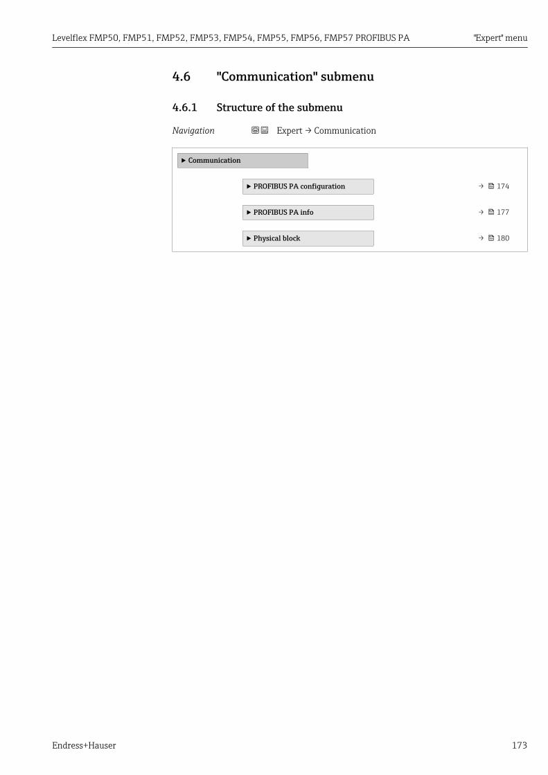
Levelflex FMP50, FMP51, FMP52, FMP53, FMP54, FMP55, FMP56, FMP57 PROFIBUS PA "Expert" menu
Endress+Hauser 173
4.6 "Communication" submenu
4.6.1 Structure of the submenu
Navigation Expert → Communication
‣ Communication
‣ PROFIBUS PA configuration → 174
‣ PROFIBUS PA info → 177
‣ Physical block → 180
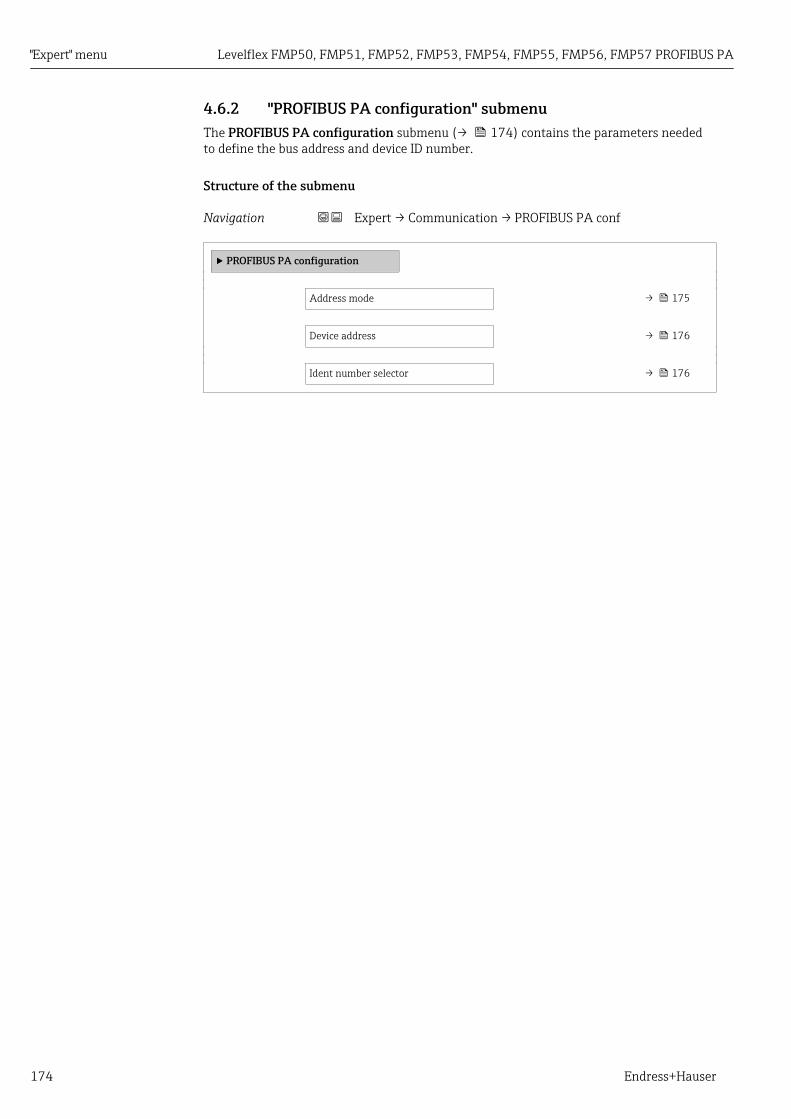
"Expert" menu Levelflex FMP50, FMP51, FMP52, FMP53, FMP54, FMP55, FMP56, FMP57 PROFIBUS PA
174 Endress+Hauser
4.6.2 "PROFIBUS PA configuration" submenuThe PROFIBUS PA configuration submenu (→ 174) contains the parameters neededto define the bus address and device ID number.
Structure of the submenu
Navigation Expert → Communication → PROFIBUS PA conf
‣ PROFIBUS PA configuration
Address mode → 175
Device address → 176
Ident number selector → 176

Levelflex FMP50, FMP51, FMP52, FMP53, FMP54, FMP55, FMP56, FMP57 PROFIBUS PA "Expert" menu
Endress+Hauser 175
Description of parameters
Navigation Expert → Communication → PROFIBUS PA conf
Address mode
Navigation Expert → Communication → PROFIBUS PA conf → Address mode (1468)
Description Displays the address mode.
Additional information Meaning of the display optionsThe address mode is defined via address switch 8 in the connection compartment:• Hardware
Address switch 8 is in the "OFF" position. Hardware addressing is therefore active: thebus address of the device is configured via address switches 1 to 7
• SoftwareAddress switch 8 is in the "ON" position. Software addressing is therefore active: the busaddress of the device is defined in the Device address parameter (→ 176).
Information on hardware addressing
2
98
34
56
78
1
DIP
ON
A0015686
54 Address switch in the connection compartment
Address switches in the "OFF" position do not contribute to the address. Address switchesin the "ON" position contribute to the address as defined in the following list:• Switch 1: Value = 1• Switch 2: Value = 2• Switch 3: Value = 4• Switch 4: Value = 8• Switch 5: Value = 16• Switch 6: Value = 32• Switch 7: Value = 64
Example
2
98
3 4 5 6 7 81
DIPON
2 + 8 = 10
A0015902

"Expert" menu Levelflex FMP50, FMP51, FMP52, FMP53, FMP54, FMP55, FMP56, FMP57 PROFIBUS PA
176 Endress+Hauser
Address switches 2 and 4 are in the "ON" position; all other address switches are in the"OFF" position
Þ Address = 2 + 8 = 10
Device address
Navigation Expert → Communication → PROFIBUS PA conf → Device address (1462)
Description • for Address mode (→ 175) = Software: Enter bus address.• for Address mode (→ 175) = Hardware: Displays bus address.
User entry 0 to 126
Factory setting 126
Ident number selector
Navigation Expert → Communication → PROFIBUS PA conf → Ident num select (1461)
Description Select ident number of the device.
Selection • Profile• FMP5x (1558hex)• FMP4x (152Dhex)• Auto
Factory setting Auto
Additional information Meaning of the options• Profile
The ident number of the PROFIBUS profiles is used.• FMP5x (1558hex)
The ident number of Levelflex FMP5x is used.• FMP4x (152Dhex)
The ident number of the previous device type, Levelflex FMP4x, is used.• Auto
The ident number can be adapted automatically by a Class I PROFIBUS master.

Levelflex FMP50, FMP51, FMP52, FMP53, FMP54, FMP55, FMP56, FMP57 PROFIBUS PA "Expert" menu
Endress+Hauser 177
4.6.3 "PROFIBUS PA info" submenuThe PROFIBUS PA info submenu contains all parameters that provide information aboutthe condition of the PROFIBUS PA interface.
Structure of the submenu
Navigation Expert → Communication → PROFIBUS PA info
‣ PROFIBUS PA info
Status PROFIBUS Master Config → 178
PROFIBUS ident number → 178
Profile version → 178
CRC Count OK → 178
CRC Count Failed → 178
Number of good between badtelegrams
→ 179
Base current → 179
Terminal voltage 1 → 179

"Expert" menu Levelflex FMP50, FMP51, FMP52, FMP53, FMP54, FMP55, FMP56, FMP57 PROFIBUS PA
178 Endress+Hauser
Description of parameters
Navigation Expert → Communication → PROFIBUS PA info
Status PROFIBUS Master Config
Navigation Expert → Communication → PROFIBUS PA info → Stat Master Conf (1465)
Description Indicates whether the cyclic data exchange with the master is currently active.
User interface • Active• Not active
PROFIBUS ident number
Navigation Expert → Communication → PROFIBUS PA info → Ident number (1471)
Description Indicates the ident number of the device.
Additional information The Ident number selector parameter (→ 176) can be used to define which identnumber is used.
Profile version
Navigation Expert → Communication → PROFIBUS PA info → Profile version (1463)
Description Displays the PROFIBUS profile version of the device.
CRC Count OK
Navigation Expert → Communication → PROFIBUS PA info → CRC Count OK (1469)
Description Indicates how many times the checksum test of the cyclic data telegram was successful.
CRC Count Failed
Navigation Expert → Communication → PROFIBUS PA info → CRC Count Failed (1470)
Description Indicates how many times the checksum test of the cyclic data telegram discovered anerror.

Levelflex FMP50, FMP51, FMP52, FMP53, FMP54, FMP55, FMP56, FMP57 PROFIBUS PA "Expert" menu
Endress+Hauser 179
Number of good between bad telegrams
Navigation Expert → Communication → PROFIBUS PA info → Good telegrams (1467)
Description Indicates how many error-free data telegrams were transmitted between the two lastfailed data telegrams.
Base current
Navigation Expert → Communication → PROFIBUS PA info → Base current (1466)
Description Displays the present current consumption at the PROFIBUS input of the device.
Terminal voltage 1
Navigation Expert → Communication → PROFIBUS PA info → Terminal volt. 1 (0662)
Expert → Communication → PROFIBUS PA info → Base current (1466)
Description Dipslays terminal voltage at the current output.
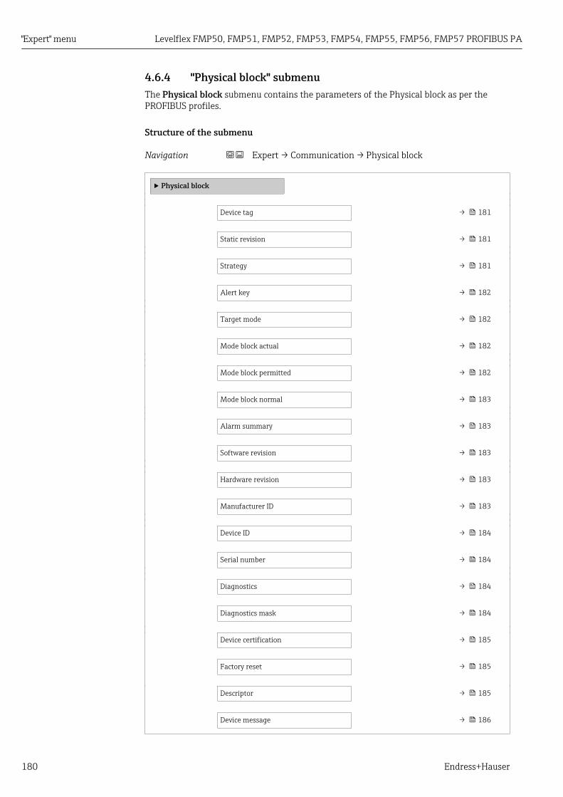
"Expert" menu Levelflex FMP50, FMP51, FMP52, FMP53, FMP54, FMP55, FMP56, FMP57 PROFIBUS PA
180 Endress+Hauser
4.6.4 "Physical block" submenuThe Physical block submenu contains the parameters of the Physical block as per thePROFIBUS profiles.
Structure of the submenu
Navigation Expert → Communication → Physical block
‣ Physical block
Device tag → 181
Static revision → 181
Strategy → 181
Alert key → 182
Target mode → 182
Mode block actual → 182
Mode block permitted → 182
Mode block normal → 183
Alarm summary → 183
Software revision → 183
Hardware revision → 183
Manufacturer ID → 183
Device ID → 184
Serial number → 184
Diagnostics → 184
Diagnostics mask → 184
Device certification → 185
Factory reset → 185
Descriptor → 185
Device message → 186

Levelflex FMP50, FMP51, FMP52, FMP53, FMP54, FMP55, FMP56, FMP57 PROFIBUS PA "Expert" menu
Endress+Hauser 181
Device install date → 186
Ident number selector → 186
Hardware lock → 186
Feature supported → 187
Feature enabled → 187
Condensed status diagnostic → 187
Descripiton of parameters
Navigation Expert → Communication → Physical block
Device tag
Navigation Expert → Communication → Physical block → Device tag (1496)
Description Enter tag for measuring point.
User entry Up to 32 alphanumerical characters
Factory setting FMP5x
Static revision
Navigation Expert → Communication → Physical block → Static revision (1495)
Description Standard block parameter ST_REV according to the PROFIBUS profile
User interface 0 to 65 535
Factory setting 0
Strategy
Navigation Expert → Communication → Physical block → Strategy (1494)
Description Standard block parameter STRATEGY according to the PROFIBUS profile
User entry 0 to 65 535

"Expert" menu Levelflex FMP50, FMP51, FMP52, FMP53, FMP54, FMP55, FMP56, FMP57 PROFIBUS PA
182 Endress+Hauser
Factory setting 0
Alert key
Navigation Expert → Communication → Physical block → Alert key (1473)
Description Standard block parameter ALERT_KEY according to the PROFIBUS profile
User entry 0 to 255
Factory setting 0
Target mode
Navigation Expert → Communication → Physical block → Target mode (1497)
Description Standard block parameter TARGET_MODE according to the PROFIBUS profile
Selection • Auto• Out of service
Factory setting Auto
Mode block actual
Navigation Expert → Communication → Physical block → Mode block act (1472)
Description Element Actual of the standard block parameter MODE_BLK according to the PROFIBUSprofile
User interface • Auto• Out of service
Mode block permitted
Navigation Expert → Communication → Physical block → Mode block perm (1493)
Description Element Permitted of the standard block parameter MODE_BLK according to thePROFIBUS profile
User interface 0 to 255

Levelflex FMP50, FMP51, FMP52, FMP53, FMP54, FMP55, FMP56, FMP57 PROFIBUS PA "Expert" menu
Endress+Hauser 183
Mode block normal
Navigation Expert → Communication → Physical block → Mode blk norm (1492)
Description Element Normal of the standard block parameter MODE_BLK according to the PROFIBUSprofile
User interface • Auto• Out of service
Alarm summary
Navigation Expert → Communication → Physical block → Alarm summary (1474)
Description Standard block parameter ALARM_SUM according to the PROFIBUS profile
User interface • Discrete alarm• Alarm state HiHi limit• Alarm state Hi limit• Alarm state LoLo limit• Alarm state Lo limit• Update Event
Software revision
Navigation Expert → Communication → Physical block → Software rev. (1478)
Description Standard parameter SOFTWARE_REVISION of the Physical block according to thePROFIBUS profile
Hardware revision
Navigation Expert → Communication → Physical block → Hardware rev. (1479)
Description Standard parameter HARDWARE_REVISION of the Physical block according to thePROFIBUS profile
Manufacturer ID
Navigation Expert → Communication → Physical block → Manufacturer ID (1502)
Description Standard parameter DEVICE_MAN_ID of the Physical block according to the PROFIBUSprofile

"Expert" menu Levelflex FMP50, FMP51, FMP52, FMP53, FMP54, FMP55, FMP56, FMP57 PROFIBUS PA
184 Endress+Hauser
User interface 0 to 65 535
Device ID
Navigation Expert → Communication → Physical block → Device ID (1480)
Description Standard parameter DEVICE_ID of the Physical block according to the PROFIBUS profile
Serial number
Navigation Expert → Communication → Physical block → Serial number (1481)
Description Standard parameter DEVICE_SER_NUM of the Physical block according to the PROFIBUSprofile
Diagnostics
Navigation Expert → Communication → Physical block → Diagnostics (1482)
Description Standard parameter DIAGNOSIS of the Physical block according to the PROFIBUS profile
User interface • Memory checksum error• Measurement error• Device not initialized• On warmstart• On coldstart• Maintenance required• Ident number violation• More information available• Maintenance alarm• Maintenance demanded• Function check or simulation• Invalid process condition• Hardware failure electronics
Diagnostics mask
Navigation Expert → Communication → Physical block → Diagnostics mask (1484)
Description Standard parameter DIAGNOSIS_MASK of the Physical block according to the PROFIBUSprofile

Levelflex FMP50, FMP51, FMP52, FMP53, FMP54, FMP55, FMP56, FMP57 PROFIBUS PA "Expert" menu
Endress+Hauser 185
User interface • Memory checksum error• Measurement error• Device not initialized• On warmstart• On coldstart• Maintenance required• Ident number violation• More information available• Maintenance alarm• Maintenance demanded• Function check or simulation• Invalid process condition• Hardware failure electronics
Device certification
Navigation Expert → Communication → Physical block → Dev certificate (1486)
Description Standard parameter DEVICE_CERTIFICATION of the Physical block according to thePROFIBUS profile
Factory reset
Navigation Expert → Communication → Physical block → Factory reset (1488)
Description Standard parameter FACTORY_RESET of the Physical block according to the PROFIBUSprofile
Selection • to defaults• warmstart device• reset bus address• Cancel
Factory setting Cancel
Descriptor
Navigation Expert → Communication → Physical block → Descriptor (1489)
Description Standard parameter DESCRIPTOR of the Physical block according to the PROFIBUS profile

"Expert" menu Levelflex FMP50, FMP51, FMP52, FMP53, FMP54, FMP55, FMP56, FMP57 PROFIBUS PA
186 Endress+Hauser
Device message
Navigation Expert → Communication → Physical block → Device message (1490)
Description Standard parameter DEVICE_MESSAGE of the Physical block according to the PROFIBUSprofile
Device install date
Navigation Expert → Communication → Physical block → Device inst.date (1491)
Description Standard parameter DEVICE_INSTAL_DATE of the Physical block according to thePROFIBUS profile
Ident number selector
Navigation Expert → Communication → Physical block → Ident num select (1461)
Description Select ident number of the device.
Selection • Profile• FMP5x (1558hex)• FMP4x (152Dhex)• Auto
Factory setting Auto
Additional information Meaning of the options• Profile
The ident number of the PROFIBUS profiles is used.• FMP5x (1558hex)
The ident number of Levelflex FMP5x is used.• FMP4x (152Dhex)
The ident number of the previous device type, Levelflex FMP4x, is used.• Auto
The ident number can be adapted automatically by a Class I PROFIBUS master.
Hardware lock
Navigation Expert → Communication → Physical block → Hardware lock (1499)
Description Standard parameter HW_WRITE_PROTECTION of the Physical block according to thePROFIBUS prfile
User interface • Unprotected• Protected

Levelflex FMP50, FMP51, FMP52, FMP53, FMP54, FMP55, FMP56, FMP57 PROFIBUS PA "Expert" menu
Endress+Hauser 187
Feature supported
Navigation Expert → Communication → Physical block → Feature support (1477)
Description Element Supported of the parameter HW_WRITE_PROTECTION in the Physical blockaccording to the PROFIBUS profile
User interface • Condensed status• Classic status diagnosis• Data exchange broadcast• MS1 application relationship• PROFIsafe communication
Feature enabled
Navigation Expert → Communication → Physical block → Feature enabled (1476)
Description Element Enabled of the parameter HW_WRITE_PROTECTION in the Physical blockaccording to the PROFIBUS profile
User interface • Condensed status• Classic status diagnosis• Data exchange broadcast• MS1 application relationship• PROFIsafe communication
Condensed status diagnostic
Navigation Expert → Communication → Physical block → Condensed status (1500)
Description Parameter COND_STATUS_DIAG in the Physical block according to the PROFIBUS profile
Selection • Off• On
Factory setting On

"Expert" menu Levelflex FMP50, FMP51, FMP52, FMP53, FMP54, FMP55, FMP56, FMP57 PROFIBUS PA
188 Endress+Hauser
4.7 "Analog input 1 to 6" submenu
4.7.1 OverviewThere is an Analog input submenu for each Analog Input block in the device. Thissubmenu contains the block parameters of the individual block. The parameters of theAnalog Input block are described in the PROFIBUS profile. The most importantcharacteristics of the parameters are summarized below. An Analog Input block can beused to scale a measured variable of the device and transmit it via the bus to a PLC, forexample.
Channel
Out ValuePROFIBUS
1 2 3
A0017058
55 Transmission of an analog value to a PLC via the Analog Input block
1 Transmitter2 Analog Input block (part of the transmitter software)3 PLC
Data processing in the Analog Input block
Simulate value HiHi alarm value
Out value
LoLo alarm value
Hi alarm value
Lo alarm value
PV scaleupper range
Simulateenable
Enable
Disable
PV scalelower range
Out scalelower range
Out scaleupper range
HiHi lim
LoLo lim
Hi lim
Lo lim
t
Out unit; Out decimal point
PV filter time
Value
Simulate status HiHi alarm state
Out state
Out unit text
LoLo alarm state
Hi alarm state
Lo alarm state
StatusChannel
A0016781
The diagram describes the function of the Analog Input block in the normaloperational state (Mode block actual (→ 192) = Auto). The block's behavior inother operational states is described in the Profibus profiles of the Profibus UserOrganization (PNO).

Levelflex FMP50, FMP51, FMP52, FMP53, FMP54, FMP55, FMP56, FMP57 PROFIBUS PA "Expert" menu
Endress+Hauser 189
4.7.2 Structure of the submenu
Navigation Expert → Analog inputs → Analog input 1 to 6
‣ Analog input 1 to 6
Tag description → 191
Static revision → 191
Strategy → 191
Alert key → 191
Target mode → 192
Mode block actual → 192
Mode block permitted → 192
Mode block normal → 192
Alarm summary → 193
Batch ID → 193
Batch operation → 193
Batch phase → 193
Batch Recipe Unit Procedure → 194
Out value → 194
Out status → 194
Out status HEX → 195
PV scale lower range → 195
PV scale upper range → 195
Out scale lower range → 196
Out scale upper range → 196
Lin type → 196
Channel → 196
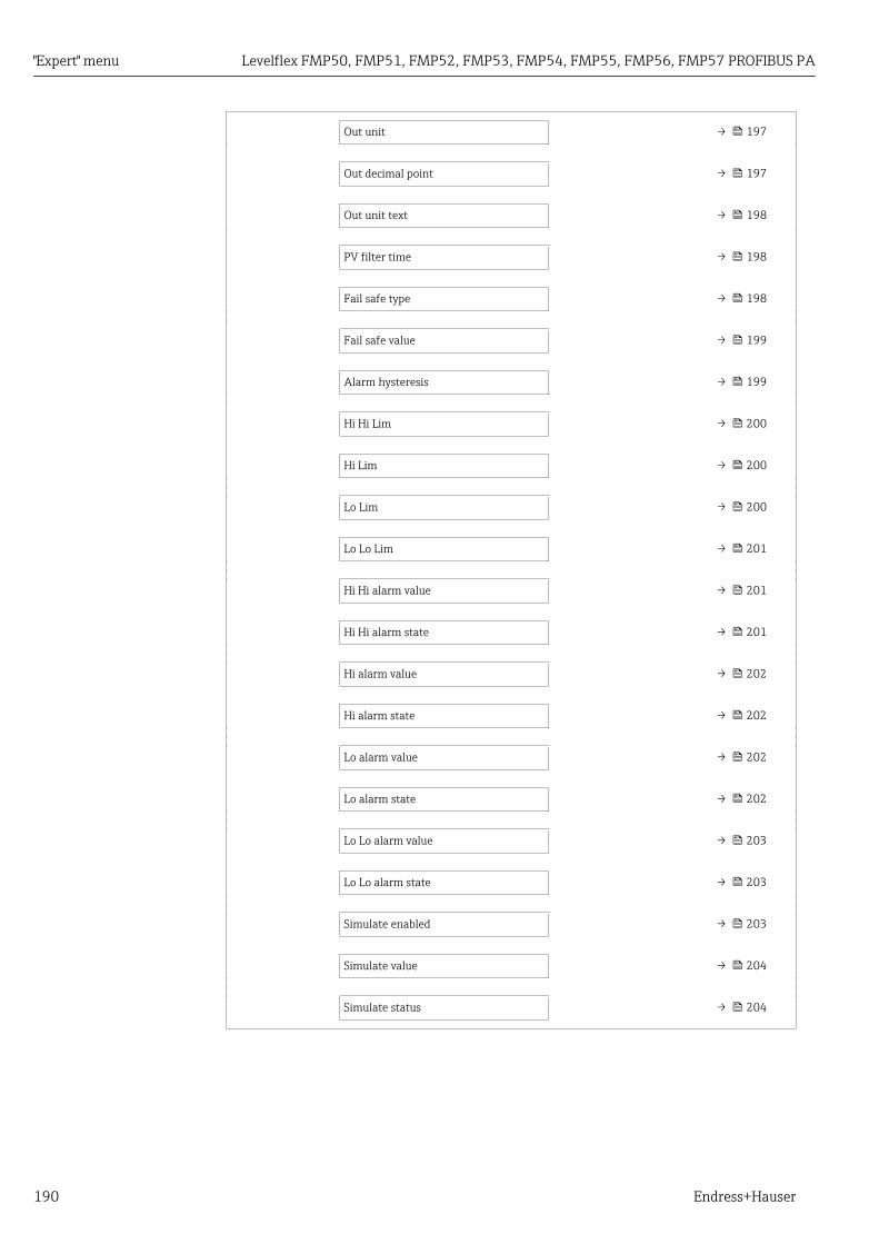
"Expert" menu Levelflex FMP50, FMP51, FMP52, FMP53, FMP54, FMP55, FMP56, FMP57 PROFIBUS PA
190 Endress+Hauser
Out unit → 197
Out decimal point → 197
Out unit text → 198
PV filter time → 198
Fail safe type → 198
Fail safe value → 199
Alarm hysteresis → 199
Hi Hi Lim → 200
Hi Lim → 200
Lo Lim → 200
Lo Lo Lim → 201
Hi Hi alarm value → 201
Hi Hi alarm state → 201
Hi alarm value → 202
Hi alarm state → 202
Lo alarm value → 202
Lo alarm state → 202
Lo Lo alarm value → 203
Lo Lo alarm state → 203
Simulate enabled → 203
Simulate value → 204
Simulate status → 204

Levelflex FMP50, FMP51, FMP52, FMP53, FMP54, FMP55, FMP56, FMP57 PROFIBUS PA "Expert" menu
Endress+Hauser 191
4.7.3 Description of parameters
Navigation Expert → Analog inputs → Analog input 1 to 6
Tag description
Navigation Expert → Analog inputs → Analog input 1 to 6 → Tag description (1562–1 to 6)
Description Standard block parameter TAG_DESC according to the PROFIBUS profile
Static revision
Navigation Expert → Analog inputs → Analog input 1 to 6 → Static revision (1560–1 to 6)
Description Standard block parameter ST_REV according to the PROFIBUS profile
User interface 0 to 65 535
Strategy
Navigation Expert → Analog inputs → Analog input 1 to 6 → Strategy (1559–1 to 6)
Description Standard block parameter STRATEGY according to the PROFIBUS profile
User entry 0 to 65 535
Factory setting 0
Alert key
Navigation Expert → Analog inputs → Analog input 1 to 6 → Alert key (1522–1 to 6)
Description Standard block parameter ALERT_KEY according to the PROFIBUS profile
User entry 0 to 255
Factory setting 0

"Expert" menu Levelflex FMP50, FMP51, FMP52, FMP53, FMP54, FMP55, FMP56, FMP57 PROFIBUS PA
192 Endress+Hauser
Target mode
Navigation Expert → Analog inputs → Analog input 1 to 6 → Target mode (1563–1 to 6)
Description Standard block parameter TARGET_MODE according to the PROFIBUS profile
Selection • Auto• Man• Out of service
Factory setting Auto
Mode block actual
Navigation Expert → Analog inputs → Analog input 1 to 6 → Mode block act (1521–1 to 6)
Description Element Actual of the standard block parameter MODE_BLK according to the PROFIBUSprofile
User interface • Auto• Man• Out of service
Mode block permitted
Navigation Expert → Analog inputs → Analog input 1 to 6 → Mode block perm (1553–1 to 6)
Description Element Permitted of the standard block parameter MODE_BLK according to thePROFIBUS profile
User interface 0 to 255
Mode block normal
Navigation Expert → Analog inputs → Analog input 1 to 6 → Mode blk norm (1546–1 to 6)
Description Element Normal of the standard block parameter MODE_BLK according to the PROFIBUSprofile
User interface • Auto• Man• Out of service
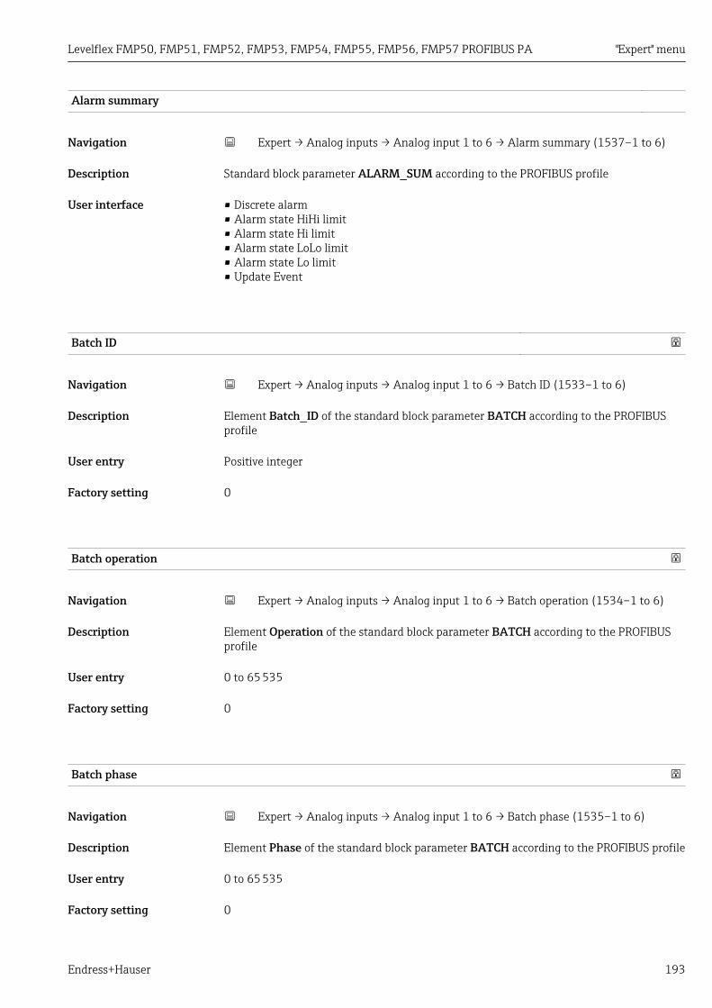
Levelflex FMP50, FMP51, FMP52, FMP53, FMP54, FMP55, FMP56, FMP57 PROFIBUS PA "Expert" menu
Endress+Hauser 193
Alarm summary
Navigation Expert → Analog inputs → Analog input 1 to 6 → Alarm summary (1537–1 to 6)
Description Standard block parameter ALARM_SUM according to the PROFIBUS profile
User interface • Discrete alarm• Alarm state HiHi limit• Alarm state Hi limit• Alarm state LoLo limit• Alarm state Lo limit• Update Event
Batch ID
Navigation Expert → Analog inputs → Analog input 1 to 6 → Batch ID (1533–1 to 6)
Description Element Batch_ID of the standard block parameter BATCH according to the PROFIBUSprofile
User entry Positive integer
Factory setting 0
Batch operation
Navigation Expert → Analog inputs → Analog input 1 to 6 → Batch operation (1534–1 to 6)
Description Element Operation of the standard block parameter BATCH according to the PROFIBUSprofile
User entry 0 to 65 535
Factory setting 0
Batch phase
Navigation Expert → Analog inputs → Analog input 1 to 6 → Batch phase (1535–1 to 6)
Description Element Phase of the standard block parameter BATCH according to the PROFIBUS profile
User entry 0 to 65 535
Factory setting 0

"Expert" menu Levelflex FMP50, FMP51, FMP52, FMP53, FMP54, FMP55, FMP56, FMP57 PROFIBUS PA
194 Endress+Hauser
Batch Recipe Unit Procedure
Navigation Expert → Analog inputs → Analog input 1 to 6 → Batch Recipe (1536–1 to 6)
Description Element Rup (Recipe unit procedure) of the standard block parameter BATCH accordingto the PROFIBUS profile
User entry 0 to 65 535
Factory setting 0
Out value
Navigation Expert → Analog inputs → Analog input 1 to 6 → Out value (1552–1 to 6)
Description Element Value of the standard parameter OUT in the Analog Input Block according to thePROFIBUS Profile.
User entry Signed floating-point number
Factory setting 0
Additional information • For Mode block actual (→ 192) = Man:Enter the output value of the Analog Input Block.
• Else:Displays the output value of the Analog Input Block.
Out status
Navigation Expert → Analog inputs → Analog input 1 to 6 → Out status (1564–1 to 6)
Description Element Status of the standard parameter OUT in the Analog Input Block accordintg tothe PROFIBUS Profile.
User interface • Good• Uncertain• Bad
Additional information Only the two quality bits are evaluated in this parameter.
Levelflex FMP50, FMP51, FMP52, FMP53, FMP54, FMP55, FMP56, FMP57 PROFIBUS PA "Expert" menu
Endress+Hauser 195
Out status HEX
Navigation Expert → Analog inputs → Analog input 1 to 6 → Out status HEX (1549–1 to 6)
Description Element Status of the standard parameter OUT in the Analog Input Block according to thePROFIBUS Profile.
User entry 0 to 255
Factory setting 128
Additional information The complete status byte is displayed in the form of a two-digit hexadecimal number inthis parameter.
PV scale lower range
Navigation Expert → Analog inputs → Analog input 1 to 6 → PVscale lo range (1554–1 to 6)
Description Element EU_at_0% of the standard parameter PV_SCALE in the Analog Input blockaccording to the PROFIBUS profile
User entry Signed floating-point number
Factory setting 0
Additional information This parameter defines the 0% marker for the input value of the block.
PV scale upper range
Navigation Expert → Analog inputs → Analog input 1 to 6 → PVscale up range (1555–1 to 6)
Description Element EU_at_100% of the standard parameter PV_SCALE in the Analog Input blockaccording to the PROFIBUS profile
User entry Signed floating-point number
Factory setting 100.0
Additional information This parameter defines the 100% marker for the input value of the block.

"Expert" menu Levelflex FMP50, FMP51, FMP52, FMP53, FMP54, FMP55, FMP56, FMP57 PROFIBUS PA
196 Endress+Hauser
Out scale lower range
Navigation Expert → Analog inputs → Analog input 1 to 6 → Out scale low (1548–1 to 6)
Description Element EU_at_0% of the standard parameter OUT_SCALE in the Analog Input blockaccording to the PROFIBUS profile
User entry Signed floating-point number
Factory setting 0
Additional information This parameter defines the 0% marker for the output value of the block.
Out scale upper range
Navigation Expert → Analog inputs → Analog input 1 to 6 → Out scale up (1551–1 to 6)
Description Element EU_at_100% of the standard parameter OUT_SCALE in the Analog Input blockaccording to the PROFIBUS profile
User entry Signed floating-point number
Factory setting 100.0
Additional information This parameter defines the 100% marker for the output value of the block.
Lin type
Navigation Expert → Analog inputs → Analog input 1 to 6 → Lin type (1523–1 to 6)
Description Standard parameter LIN_TYPE of the Analog Input block according to the PROFIBUSprofile
Selection Off
Factory setting Off
Channel
Navigation Expert → Analog inputs → Analog input 1 to 6 → Channel (1561–1 to 6)
Description Standard parameter CHANNEL of the Analog Input Block according to the PROFIBUSProfile.

Levelflex FMP50, FMP51, FMP52, FMP53, FMP54, FMP55, FMP56, FMP57 PROFIBUS PA "Expert" menu
Endress+Hauser 197
Selection • Level linearized• Distance• Interface linearized 16)
• Interface distance 16)
• Thickness upper layer 16)
• Terminal voltage• Electronic temperature• Measured capacitance 16)
• Absolute echo amplitude• Relative echo amplitude• Absolute interface amplitude 16)
• Relative interface amplitude 16)
• Absolute EOP amplitude• Noise of signal• EOP shift• Calculated DC value 16)
• Sensor debug• Analog output adv. diagnostics 1• Analog output adv. diagnostics 2
Factory setting Level linearized
Additional information Allocates a measured value to the AI block.
Out unit
Navigation Expert → Analog inputs → Analog input 1 to 6 → Out unit (1550–1 to 6)
Description Element Units_Index of the standard parameter OUT_SCALE in the Analog Input blockaccording to the PROFIBUS profile
User entry 0 to 65 535
Factory setting 1 997
Additional information This parameter defines the unit for the output value. The units are represented by anumeric code according to the PROFIBUS profile.
Out decimal point
Navigation Expert → Analog inputs → Analog input 1 to 6 → Out dec_ point (1547–1 to 6)
Description Element Decimal_Point of the standard parameter OUT_SCALE in the Analog Input blockaccording to the PROFIBUS profile
User entry 0 to 7
Factory setting 0
16) Visibility depends on order options or device settings
"Expert" menu Levelflex FMP50, FMP51, FMP52, FMP53, FMP54, FMP55, FMP56, FMP57 PROFIBUS PA
198 Endress+Hauser
Additional information This parameter defines up to which decimal the output value is to be considered valid.
Out unit text
Navigation Expert → Analog inputs → Analog input 1 to 6 → Out unit text (1532–1 to 6)
Description Standard block parameter OUT_UNIT_TEXT in the Analog Input block according to thePROFIBUS profile
Factory setting NoUnit
Additional information This text is used as unit if Out unit (→ 197) = 1995: Textual unit.
PV filter time
Navigation Expert → Analog inputs → Analog input 1 to 6 → PV filter time (1524–1 to 6)
Description Standard parameter PV_FTIME of the Analog Input Block according to the PROFIBUSprofile.
User entry Positive floating-point number
Factory setting 0
Additional information This parameter defines the damping constant τ (in seconds) for the output of the AnalogInput Block.
Fail safe type
Navigation Expert → Analog inputs → Analog input 1 to 6 → Fail safe type (1525–1 to 6)
Description Standard parameter FSAFE_TYPE of the Analog Input Block according to the PROFIBUSprofile.
Selection • Fail safe value• Fallback value• Off
Factory setting Off

Levelflex FMP50, FMP51, FMP52, FMP53, FMP54, FMP55, FMP56, FMP57 PROFIBUS PA "Expert" menu
Endress+Hauser 199
Additional information Meaning of the optionsThis parameter specifies the output value of the Analog Input block in the event of anerror.• Fail safe value
The output value in the event of an error is defined in the Fail safe value parameter(→ 199).
• Fallback valueThe last output value that was valid before the error occurred is retained.
• OffThe output value follows the current measured value. The status is set to BAD.
Fail safe value
Navigation Expert → Analog inputs → Analog input 1 to 6 → Fail safe value (1526–1 to 6)
Prerequsite Fail safe type (→ 198) = Fail safe value
Description Standard parameter FSAFE_VALUE of the Analog Input Block according to the PROFIBUSprofile.
User entry Signed floating-point number
Factory setting 0
Additional information This parameter defines the output value of the Analog Input Block in case of an error.
Alarm hysteresis
Navigation Expert → Analog inputs → Analog input 1 to 6 → Alarm hysteresis (1527–1 to 6)
Description Standard parameter ALARM_HYS of the Analog Input block according to the PROFIBUSprofile
User entry Signed floating-point number
Factory setting 0
Additional information This parameter defines the hysteresis for limit violation of the output value in the AnalogInput block. The hysteresis is specified in the same unit as the output value (Out unitparameter (→ 197)).

"Expert" menu Levelflex FMP50, FMP51, FMP52, FMP53, FMP54, FMP55, FMP56, FMP57 PROFIBUS PA
200 Endress+Hauser
Hi Hi Lim
Navigation Expert → Analog inputs → Analog input 1 to 6 → Hi Hi Lim (1528–1 to 6)
Description Standard parameter HI_HI_LIM of the Analog Input block according to the PROFIBUSprofile
User entry Signed floating-point number
Factory setting Positive floating-point number
Additional information An alarm is generated if the output value of the Analog Input block rises above this value.
For a consistent evaluation of the output staus, the limit values must be defined inascending order:
Lo Lo Lim < Lo Lim < Hi Lim < Hi Hi Lim
Hi Lim
Navigation Expert → Analog inputs → Analog input 1 to 6 → Hi Lim (1529–1 to 6)
Description Standard parameter HI_LIM in the Analog Input block according to the PROFIBUS profile
User entry Signed floating-point number
Factory setting Positive floating-point number
Additional information An alarm is generated if the output value of the Analog Input block rises above this value.
For a consistent evaluation of the output status, the limit values must be defined inascending order:
Lo Lo Lim < Lo Lim < Hi Lim < Hi Hi Lim
Lo Lim
Navigation Expert → Analog inputs → Analog input 1 to 6 → Lo Lim (1530–1 to 6)
Description Standard parameter LO_LIM of the Analog Input block according to the PROFIBUS profile
User entry Signed floating-point number
Factory setting Negative floating-point number
Additional information An alarm is generated if the output value of the Analog Input block falls below this value.
For a consistent evaluation fo the output status, the limit values must be defined inascending order:
Lo Lo Lim < Lo Lim < Hi Lim < Hi Hi Lim

Levelflex FMP50, FMP51, FMP52, FMP53, FMP54, FMP55, FMP56, FMP57 PROFIBUS PA "Expert" menu
Endress+Hauser 201
Lo Lo Lim
Navigation Expert → Analog inputs → Analog input 1 to 6 → Lo Lo Lim (1531–1 to 6)
Description Standard parameter LO_LO_LIM of the Analog Input block according to the PROFIBUSprofile
User entry Signed floating-point number
Factory setting Negative floating-point number
Additional information An alarm is generated if the output value of the Analog Input block falls below this value.
For a consistent evaluation of the output status, the limit values must be defined inascending order:
Lo Lo Lim < Lo Lim < Hi Lim < Hi Hi Lim
Hi Hi alarm value
Navigation Expert → Analog inputs → Analog input 1 to 6 → HiHi alarm value (1541–1 to 6)
Description Element Value of the standard parameter HI_HI_ALM in the Analog Input blockaccording to the PROFIBUS profile
User interface Signed floating-point number
Additional information This parameter displays the output value which caused the alarm.
Hi Hi alarm state
Navigation Expert → Analog inputs → Analog input 1 to 6 → HiHi alarm state (1540–1 to 6)
Description Element Alarm_State of the standard parameter HI_HI_ALM in the Analog Input blockaccording to the PROFIBUS profile
User interface • No alarm• Alarm state HiHi limit
Additional information This parameter indicates whether an alarm caused by Hi Hi Lim violation is currentlyactive.

"Expert" menu Levelflex FMP50, FMP51, FMP52, FMP53, FMP54, FMP55, FMP56, FMP57 PROFIBUS PA
202 Endress+Hauser
Hi alarm value
Navigation Expert → Analog inputs → Analog input 1 to 6 → Hi alarm value (1539–1 to 6)
Description Element Value of the standard parameter HI_ALM in the Analog Input block according tothe PROFIBUS profile
User interface Signed floating-point number
Additional information This parameter displays the output value which caused the alarm.
Hi alarm state
Navigation Expert → Analog inputs → Analog input 1 to 6 → Hi alarm state (1538–1 to 6)
Description Element Alarm_State of the standard parameter HI_ALM in the Analog Input blockaccording to the PROFIBUS profile
User interface • No warning• Alarm state Hi limit
Additional information This parameter indicates whether an alarm caused by a Hi Lim violation is currently active.
Lo alarm value
Navigation Expert → Analog inputs → Analog input 1 to 6 → Lo alarm value (1543–1 to 6)
Description Element Value of the standard parameter LO_ALM in the Analog Input block according tothe PROFIBUS profile
User interface Signed floating-point number
Additional information This parameter displays the output value which caused the alarm.
Lo alarm state
Navigation Expert → Analog inputs → Analog input 1 to 6 → Lo alarm state (1542–1 to 6)
Description Element Alarm_State of the standard parameter LO_ALM in the Analog Input blockaccording to the PROFIBUS profile
User interface • No warning• Alarm state Lo limit
Additional information This parameter indicates whether an alarm caused by a Lo Lim violation is currently active.

Levelflex FMP50, FMP51, FMP52, FMP53, FMP54, FMP55, FMP56, FMP57 PROFIBUS PA "Expert" menu
Endress+Hauser 203
Lo Lo alarm value
Navigation Expert → Analog inputs → Analog input 1 to 6 → LoLo alarm value (1545–1 to 6)
Description Element Value of the standard parameter LO_LO_ALM in the Analog Input blockaccording to the PROFIBUS profile
User interface Signed floating-point number
Additional information This parameter displays the output value which caused the alarm.
Lo Lo alarm state
Navigation Expert → Analog inputs → Analog input 1 to 6 → LoLo alarm state (1544–1 to 6)
Description Element Alarm_State of the standard parameter LO_LO_ALM in the Analog Input blockaccording to the PROFIBUS profile
User interface • No alarm• Alarm state LoLo limit
Additional information This parameter indicates whether an alarm caused by a Lo Lo Lim violation is currentlyactive.
Simulate enabled
Navigation Expert → Analog inputs → Analog input 1 to 6 → Simulate enabled (1556–1 to 6)
Description Element Simulate_Enabled of the standard parameter SIMULATE in the Analog Inputblock according to the PROFIBUS profile
Selection • Disable• Enable
Factory setting Disable
Additional information Enables or disables the simulation of the Analog Input block. If the simulation is enabled,the Analog Input block uses a constant simulation value instead of the measured valueselected in Channel (→ 196). This value is specified in Simulate value (→ 204).The associated status is specified in Simulate status (→ 204).

"Expert" menu Levelflex FMP50, FMP51, FMP52, FMP53, FMP54, FMP55, FMP56, FMP57 PROFIBUS PA
204 Endress+Hauser
Simulate value
Navigation Expert → Analog inputs → Analog input 1 to 6 → Simulate value (1558–1 to 6)
Description Element Simulate_Value of the standard parameter SIMULATE in the Analog Input blocaccording to the PROFIBUS profile
User entry Signed floating-point number
Factory setting 0
Additional information This parameter defines the simulation value.
Simulate status
Navigation Expert → Analog inputs → Analog input 1 to 6 → Simulate status (1557–1 to 6)
Description Element Simulate_Status of the standard parameter SIMULATE in the Analog Inputblock according to the PROFIBUS profile
User entry 0 to 255
Factory setting 0
Additional information This parameter defines the status of the simulation value.

Levelflex FMP50, FMP51, FMP52, FMP53, FMP54, FMP55, FMP56, FMP57 PROFIBUS PA "Expert" menu
Endress+Hauser 205
4.8 "Discrete input 1 to 4" submenu
4.8.1 ÜbersichtThere is a Discrete input submenu for each Discrete Input block in the device. It containsthe block parameters of the respective block. The parameters of the Discrete Input blockare described in the PROFIBUS profile. The most important characteristics of theparameters are summarized below. A Discrete Input block can be used to transmit adiscrete measured variable via the bus to a PLC, for example.
Channel
Out ValuePROFIBUS
1 2 3
A0017058
56 Transmission of a discrete value to a PLC via the Discrete Input block
1 Transmitter2 Discrete Input block (part of transmitter software)3 PLC
Data processing in the Discrete Input block
Simulate value
Invert
Enable
off
on
Disable
Value
Simulate status
StatusChannel
TRUE TRUE
TRUE FALSE
FALSE FALSE
FALSE TRUE
Out value
Out stateSimulateenable
A0016782
The diagram describes the function of the Discrete Input block in the normaloperational state (Mode block actual (→ 209) = Auto). The block's behavior inother operational states is described in the Profibus profiles of the Profibus UserOrganization (PNO).

"Expert" menu Levelflex FMP50, FMP51, FMP52, FMP53, FMP54, FMP55, FMP56, FMP57 PROFIBUS PA
206 Endress+Hauser
4.8.2 Structure of the submenu
Navigation Expert → Discrete inputs → Discrete input 1 to 4
‣ Discrete input 1 to 4
Tag description → 208
Static revision → 208
Strategy → 208
Alert key → 208
Target mode → 209
Mode block actual → 209
Mode block permitted → 209
Mode block normal → 209
Alarm summary → 210
Batch ID → 210
Batch operation → 210
Batch phase → 210
Batch Recipe Unit Procedure → 211
Out value → 211
Out status → 211
Out status HEX → 212
Channel → 212
Invert → 212
Fail safe type → 213
Fail safe value → 213
Simulate enabled → 213

Levelflex FMP50, FMP51, FMP52, FMP53, FMP54, FMP55, FMP56, FMP57 PROFIBUS PA "Expert" menu
Endress+Hauser 207
Simulate value → 214
Simulate status → 214

"Expert" menu Levelflex FMP50, FMP51, FMP52, FMP53, FMP54, FMP55, FMP56, FMP57 PROFIBUS PA
208 Endress+Hauser
4.8.3 Description of parameters
Navigation Expert → Discrete inputs → Discrete input 1 to 4
Tag description
Navigation Expert → Discrete inputs → Discrete input 1 to 4 → Tag description (2201–1 to 4)
Description Standard block parameter TAG_DESC according to the PROFIBUS profile
Static revision
Navigation Expert → Discrete inputs → Discrete input 1 to 4 → Static revision (2200–1 to 4)
Description Standard block parameter ST_REV according to the PROFIBUS profile
User interface 0 to 65 535
Strategy
Navigation Expert → Discrete inputs → Discrete input 1 to 4 → Strategy (2199–1 to 4)
Description Standard block parameter STRATEGY according to the PROFIBUS profile
User entry 0 to 65 535
Factory setting 0
Alert key
Navigation Expert → Discrete inputs → Discrete input 1 to 4 → Alert key (2182–1 to 4)
Description Standard block parameter ALERT_KEY according to the PROFIBUS profile
User entry 0 to 255
Factory setting 0

Levelflex FMP50, FMP51, FMP52, FMP53, FMP54, FMP55, FMP56, FMP57 PROFIBUS PA "Expert" menu
Endress+Hauser 209
Target mode
Navigation Expert → Discrete inputs → Discrete input 1 to 4 → Target mode (2202–1 to 4)
Description Standard block parameter TARGET_MODE according to the PROFIBUS profile
Selection • Auto• Man• Out of service
Factory setting Auto
Mode block actual
Navigation Expert → Discrete inputs → Discrete input 1 to 4 → Mode block act (2181–1 to 4)
Description Element Actual of the standard block parameter MODE_BLK according to the PROFIBUSprofile
User interface • Auto• Man• Out of service
Mode block permitted
Navigation Expert → Discrete inputs → Discrete input 1 to 4 → Mode block perm (2195–1 to 4)
Description Element Permitted of the standard block parameter MODE_BLK according to thePROFIBUS profile
User interface 0 to 255
Mode block normal
Navigation Expert → Discrete inputs → Discrete input 1 to 4 → Mode blk norm (2192–1 to 4)
Description Element Normal of the standard block parameter MODE_BLK according to the PROFIBUSprofile
User interface • Auto• Man• Out of service

"Expert" menu Levelflex FMP50, FMP51, FMP52, FMP53, FMP54, FMP55, FMP56, FMP57 PROFIBUS PA
210 Endress+Hauser
Alarm summary
Navigation Expert → Discrete inputs → Discrete input 1 to 4 → Alarm summary (2191–1 to 4)
Description Standard block parameter ALARM_SUM according to the PROFIBUS profile
User interface • Discrete alarm• Alarm state HiHi limit• Alarm state Hi limit• Alarm state LoLo limit• Alarm state Lo limit• Update Event
Batch ID
Navigation Expert → Discrete inputs → Discrete input 1 to 4 → Batch ID (2183–1 to 4)
Description Element Batch_ID of the standard block parameter BATCH according to the PROFIBUSprofile
User entry Positive integer
Factory setting 0
Batch operation
Navigation Expert → Discrete inputs → Discrete input 1 to 4 → Batch operation (2184–1 to 4)
Description Element Operation of the standard block parameter BATCH according to the PROFIBUSprofile
User entry 0 to 65 535
Factory setting 0
Batch phase
Navigation Expert → Discrete inputs → Discrete input 1 to 4 → Batch phase (2185–1 to 4)
Description Element Phase of the standard block parameter BATCH according to the PROFIBUS profile
User entry 0 to 65 535
Factory setting 0

Levelflex FMP50, FMP51, FMP52, FMP53, FMP54, FMP55, FMP56, FMP57 PROFIBUS PA "Expert" menu
Endress+Hauser 211
Batch Recipe Unit Procedure
Navigation Expert → Discrete inputs → Discrete input 1 to 4 → Batch Recipe (2186–1 to 4)
Description Element Rup (Recipe unit procedure) of the standard block parameter BATCH accordingto the PROFIBUS profile
User entry 0 to 65 535
Factory setting 0
Out value
Navigation Expert → Discrete inputs → Discrete input 1 to 4 → Out value (2194–1 to 4)
Description Element Value of the standard parameter OUT_D in the Discrete Input block according tothe PROFIBUS profile
User entry 0 to 255
Factory setting 0
Additional information • For Mode block actual (→ 209) = Man:Enter the output value of the Discrete Input block.
• Else:Displays the output value of the Discrete Input block.
The display or input format is a two-digit hexadecimal number. This corresponds to theouput value of the DI block as follows:• Out value = 00 → FALSE• Out value ≠ 00 → TRUE
Out status
Navigation Expert → Discrete inputs → Discrete input 1 to 4 → Out status (2203–1 to 4)
Description Element Status of the standard parameter OUT_D in the Discrete Input Block according tothe PROFIBUS profile
User interface • Good• Uncertain• Bad
Additional information Only the two quality bits are evaluated in this parameter.

"Expert" menu Levelflex FMP50, FMP51, FMP52, FMP53, FMP54, FMP55, FMP56, FMP57 PROFIBUS PA
212 Endress+Hauser
Out status HEX
Navigation Expert → Discrete inputs → Discrete input 1 to 4 → Out status HEX (2193–1 to 4)
Description Element Status of the standard parameter OUT in the Discrete Input block according tothe PROFIBUS profile.
User entry 0 to 255
Factory setting 128
Additional information The complete status byte is displayed in this parameter in the form of a two-digithexadecimal number.
Channel
Navigation Expert → Discrete inputs → Discrete input 1 to 4 → Channel (2187–1 to 4)
Description Standard parameter CHANNEL of the Discrete Input Block according to the PROFIBUSprofile
Selection • None• Switch output• Digital output AD 1• Digital output AD 2
Factory setting None
Additional information This parameter allocates a switching variable to the Discrete Input Block.
Invert
Navigation Expert → Discrete inputs → Discrete input 1 to 4 → Invert (2188–1 to 4)
Description Standard parameter INVERT of the Discrete Input block according to the PROFIBUS profile
Selection • Off• On
Factory setting Off
Additional information The discrete output signal can be inverted by this parameter (permutation of the logicalstates FALSE and TRUE)
Meaning of the options:• Off
No inversion• On
The switching signal is inverted before the transmission to the bus.

Levelflex FMP50, FMP51, FMP52, FMP53, FMP54, FMP55, FMP56, FMP57 PROFIBUS PA "Expert" menu
Endress+Hauser 213
Fail safe type
Navigation Expert → Discrete inputs → Discrete input 1 to 4 → Fail safe type (2189–1 to 4)
Description Standard parameter FSAFE_TYPE of the Discrete Input block according to the PROFIBUSprofile
Selection • Fail safe value• Fallback value• Off
Factory setting Off
Additional information Meaning of the optionsThis parameter defines the output value of the Discrete Input block in case of a failure.• Fail safe value
The output value in case of a failure is defined in the Fail safe value parameter(→ 213).
• Fallback valueThe last output value before occurence of the failure is kept.
• OffThe output follows the measuring value. The status is set to BAD.
Fail safe value
Navigation Expert → Discrete inputs → Discrete input 1 to 4 → Fail safe value (2190–1 to 4)
Prerequsite Fail safe type (→ 213) = Fail safe value
Description Standard parameter FSAFE_VAL_D of the Discrete Input block according to the PROFIBUSprofile
User entry 0 to 255
Factory setting 0
Additional information This parameter defines the output value of the Discrete Input block in case of a failure.
Simulate enabled
Navigation Expert → Discrete inputs → Discrete input 1 to 4 → Simulate enabled (2196–1 to 4)
Description Element Simulate_Enabled of the standard parameter SIMULATE_D in the DiscreteInput block according to the PROFIBUS profile
Selection • Disable• Enable
Factory setting Disable

"Expert" menu Levelflex FMP50, FMP51, FMP52, FMP53, FMP54, FMP55, FMP56, FMP57 PROFIBUS PA
214 Endress+Hauser
Additional information This parameter activates or deactivates the simulation of the Discrete Input block. If thesimulation is active, the Discrete Input block does not use the measured value selected inChannel (→ 212) but a constant simulation value. This value is defined in Simulatevalue (→ 214).
Simulate value
Navigation Expert → Discrete inputs → Discrete input 1 to 4 → Simulate value (2198–1 to 4)
Description Element Simulate_Value of the standard parameter SIMULATE_D in the Discrete Inputblock according to the PROFIBUS profile
User entry 0 to 255
Factory setting 0
Additional information This parameter defines the simulation value.
Simulate status
Navigation Expert → Discrete inputs → Discrete input 1 to 4 → Simulate status (2197–1 to 4)
Description Element Simulate_Status of the standard parameter SIMULATE_D in the Discrete Inputblock according to the PROFIBUS profile
User entry 0 to 255
Factory setting 0
Additional information This parameter defines the status of the simulation value.

Levelflex FMP50, FMP51, FMP52, FMP53, FMP54, FMP55, FMP56, FMP57 PROFIBUS PA "Expert" menu
Endress+Hauser 215
4.9 "Analog output 1 to 4" submenu
4.9.1 OverviewThere is an Analog output submenu for each Analog Output block in the device. Thissubmenu contains the parameters of the individual block. The parameters of the AnalogOutput block are described in the PROFIBUS profile. The most important characteristics ofthe parameters are summarized below.
The device uses the Analog Output block to read in a value, which has been measuredexternally, via the bus. This value can be used
• for display on the display module (Display submenu (→ 33))• in the case of a pressure value: for the automatic gas phase compensation (External
pressure selector parameter (→ 111))
2
ENDRESS + HAUSER
P
P
1
4
2
3
A0016304
57 The level transmitter reads the externally measured pressure via the Analog output block.
1 Level transmitter2 Segment coupler3 PLC4 Absolute pressure transmitter

"Expert" menu Levelflex FMP50, FMP51, FMP52, FMP53, FMP54, FMP55, FMP56, FMP57 PROFIBUS PA
216 Endress+Hauser
Data processing in the Analog Output block
Set point value Out value
PV scaleupper range
PV scalelower range
Out scalelower range
Out scaleupper range
Set point status Out status
A0016954
The diagram describes the function of the Analog Output block in the normaloperational state (Mode block actual (→ 220) = Auto). The block's behavior inother operational states is described in the Profibus profiles of the Profibus UserOrganization (PNO).

Levelflex FMP50, FMP51, FMP52, FMP53, FMP54, FMP55, FMP56, FMP57 PROFIBUS PA "Expert" menu
Endress+Hauser 217
4.9.2 Structure of the submenu
Navigation Expert → Analog outputs → Analog output 1 to 4
‣ Analog output 1 to 4
Tag description → 219
Static revision → 219
Strategy → 219
Alert key → 219
Target mode → 220
Mode block actual → 220
Mode block permitted → 220
Mode block normal → 220
Alarm summary → 221
Batch ID → 221
Batch operation → 221
Batch phase → 222
Batch Recipe Unit Procedure → 222
Set point value → 222
Set point status → 222
PV scale lower range → 223
PV scale upper range → 223
Readback value → 223
Readback status → 223
RCAS in value → 224
RCAS in status → 224
Input channel → 224

"Expert" menu Levelflex FMP50, FMP51, FMP52, FMP53, FMP54, FMP55, FMP56, FMP57 PROFIBUS PA
218 Endress+Hauser
Output channel → 224
Fail safe time → 225
Fail safe type → 225
Fail safe value → 225
RCAS out value → 226
RCAS out status → 226
Position value → 226
Position status → 226
Setpoint deviation → 227
Simulate enabled → 227
Simulate value → 227
Simulate status → 227
Increase close → 228
Out value → 228
Out status → 228
Out status HEX → 229
Out scale upper range → 229
Out scale lower range → 229

Levelflex FMP50, FMP51, FMP52, FMP53, FMP54, FMP55, FMP56, FMP57 PROFIBUS PA "Expert" menu
Endress+Hauser 219
4.9.3 Description of parameters
Navigation Expert → Analog outputs → Analog output 1 to 4
Tag description
Navigation Expert → Analog outputs → Analog output 1 to 4 → Tag description (1667–1 to 4)
Description Standard block parameter TAG_DESC according to the PROFIBUS profile
Static revision
Navigation Expert → Analog outputs → Analog output 1 to 4 → Static revision (1666–1 to 4)
Description Standard block parameter ST_REV according to the PROFIBUS profile
User interface 0 to 65 535
Strategy
Navigation Expert → Analog outputs → Analog output 1 to 4 → Strategy (1665–1 to 4)
Description Standard block parameter STRATEGY according to the PROFIBUS profile
User entry 0 to 65 535
Factory setting 0
Alert key
Navigation Expert → Analog outputs → Analog output 1 to 4 → Alert key (1632–1 to 4)
Description Standard block parameter ALERT_KEY according to the PROFIBUS profile
User entry 0 to 255
Factory setting 0

"Expert" menu Levelflex FMP50, FMP51, FMP52, FMP53, FMP54, FMP55, FMP56, FMP57 PROFIBUS PA
220 Endress+Hauser
Target mode
Navigation Expert → Analog outputs → Analog output 1 to 4 → Target mode (1668–1 to 4)
Description Standard block parameter TARGET_MODE according to the PROFIBUS profile
Selection • Auto• Local override• Man• Out of service• Remote Cascaded
Factory setting Auto
Mode block actual
Navigation Expert → Analog outputs → Analog output 1 to 4 → Mode block act (1631–1 to 4)
Description Element Actual of the standard block parameter MODE_BLK according to the PROFIBUSprofile
User interface • Auto• Local override• Man• Out of service• Remote Cascaded
Mode block permitted
Navigation Expert → Analog outputs → Analog output 1 to 4 → Mode block perm (1648–1 to 4)
Description Element Permitted of the standard block parameter MODE_BLK according to thePROFIBUS profile
User interface 0 to 255
Mode block normal
Navigation Expert → Analog outputs → Analog output 1 to 4 → Mode blk norm (1643–1 to 4)
Description Element Normal of the standard block paramete MODE_BLK according to the PROFIBUSprofile
Levelflex FMP50, FMP51, FMP52, FMP53, FMP54, FMP55, FMP56, FMP57 PROFIBUS PA "Expert" menu
Endress+Hauser 221
User interface • Auto• Local override• Man• Out of service• Remote Cascaded
Alarm summary
Navigation Expert → Analog outputs → Analog output 1 to 4 → Alarm summary (1642–1 to 4)
Description Standard block parameter ALARM_SUM according to the PROFIBUS profile
User interface • Discrete alarm• Alarm state HiHi limit• Alarm state Hi limit• Alarm state LoLo limit• Alarm state Lo limit• Update Event
Batch ID
Navigation Expert → Analog outputs → Analog output 1 to 4 → Batch ID (1633–1 to 4)
Description Element Batch_ID of the standard block parameter BATCH according to the PROFIBUSprofile
User entry Positive integer
Factory setting 0
Batch operation
Navigation Expert → Analog outputs → Analog output 1 to 4 → Batch operation (1639–1 to 4)
Description Element Operation of the standard block parameter BATCH according to the PROFIBUSprofile
User entry 0 to 65 535
Factory setting 0

"Expert" menu Levelflex FMP50, FMP51, FMP52, FMP53, FMP54, FMP55, FMP56, FMP57 PROFIBUS PA
222 Endress+Hauser
Batch phase
Navigation Expert → Analog outputs → Analog output 1 to 4 → Batch phase (1640–1 to 4)
Description Element Phase of the standard block parameter BATCH according to the PROFIBUS profile
User entry 0 to 65 535
Factory setting 0
Batch Recipe Unit Procedure
Navigation Expert → Analog outputs → Analog output 1 to 4 → Batch Recipe (1641–1 to 4)
Description Element Rup (Recipe unit procedure) of the standard block parameter BATCH accordingto the PROFIBUS profile
User entry 0 to 65 535
Factory setting 0
Set point value
Navigation Expert → Analog outputs → Analog output 1 to 4 → Set point val (1661–1 to 4)
Description Input value of the AO block
User entry Signed floating-point number
Factory setting 0
Additional information This value is normally written via PROFIBUS by a linked device (e.g. a pressuretransmitter). It can be scaled by the AO block before being transmitted to Out value(→ 228) and is then used for the display or for additional calculations.
Set point status
Navigation Expert → Analog outputs → Analog output 1 to 4 → Set point status (1660–1 to 4)
Description Hexidecimal representation of the status of the input value
User entry 0 to 255
Factory setting 0

Levelflex FMP50, FMP51, FMP52, FMP53, FMP54, FMP55, FMP56, FMP57 PROFIBUS PA "Expert" menu
Endress+Hauser 223
Additional information Normally, this value is written via PROFIBUS by a linked device (e.g. a pressuretransmitter).
PV scale lower range
Navigation Expert → Analog outputs → Analog output 1 to 4 → PVscale lo range (1651–1 to 4)
Description Element EU_at_0% of the standard parameter PV_SCALE in the Analog Output blockaccording to the PROFIBUS profile
User entry Signed floating-point number
Factory setting 0
Additional information This parameter defines the 0% marker for the input value.
PV scale upper range
Navigation Expert → Analog outputs → Analog output 1 to 4 → PVscale up range (1652–1 to 4)
Description Element EU_at_100% of the standard parameter PV_SCALE in the Analog Output blockaccording to the PROFIBUS profile
User entry Signed floating-point number
Factory setting 100.0
Additional information This parameter defines the 100% marker for the input value.
Readback value
Navigation Expert → Analog outputs → Analog output 1 to 4 → Readback value (1659–1 to 4)
Description Element Value of the standard parameter READBACK in the Analog Output block
User interface Signed floating-point number
Readback status
Navigation Expert → Analog outputs → Analog output 1 to 4 → Readback status (1658–1 to 4)
Description Element Status of the standard parameter READBACK in the Analog Output block
"Expert" menu Levelflex FMP50, FMP51, FMP52, FMP53, FMP54, FMP55, FMP56, FMP57 PROFIBUS PA
224 Endress+Hauser
User interface 0 to 255
RCAS in value
Navigation Expert → Analog outputs → Analog output 1 to 4 → RCAS in value (1655–1 to 4)
Description Element Value of the standard parameter RCAS_IN in the Analog Output block accordingto the PROFIBUS profile
User entry Signed floating-point number
Factory setting 0
RCAS in status
Navigation Expert → Analog outputs → Analog output 1 to 4 → RCAS in status (1654–1 to 4)
Description Element Status of the standard parameter RCAS_IN in the Analog Input block accordingto the PROFIBUS profile
User entry 0 to 255
Factory setting 0
Input channel
Navigation Expert → Analog outputs → Analog output 1 to 4 → Input channel (1670–1 to 4)
Description Standard parameter IN_CHANNEL of the Analog Output block according to the PROFIBUSprofile
Selection None
Factory setting None
Output channel
Navigation Expert → Analog outputs → Analog output 1 to 4 → Output channel (1671–1 to 4)
Description Standard parameter OUT-CHANNEL of the Analog Output block according to thePROFIBUS profile
Selection None

Levelflex FMP50, FMP51, FMP52, FMP53, FMP54, FMP55, FMP56, FMP57 PROFIBUS PA "Expert" menu
Endress+Hauser 225
Factory setting None
Fail safe time
Navigation Expert → Analog outputs → Analog output 1 to 4 → Fail safe time (1635–1 to 4)
Description Standard parameter FSAFE_TIME of the Analog Output block according to the PROFIBUSprofile
User entry 0 to 999.0
Factory setting 0
Additional information Defines the time (in seconds) between the occurrence of an error in the set point (Setpoint status (→ 222) = BAD) and the corresponding reaction of the AO block.
Fail safe type
Navigation Expert → Analog outputs → Analog output 1 to 4 → Fail safe type (1636–1 to 4)
Description Standard parameter FSAFE_TYPE of the Analog Output block according to the PROFIBUSprofile
Selection • Fail safe value• Fallback value• Off
Factory setting Fallback value
Additional information Meaning of the optionsThis parameter defines the output value of the Analog Output block in case of an error.• Fail safe value
The output value in case of an error is defined in the Fail safe value parameter(→ 225).
• Fallback valueThe last valid output value before the occurence of the error is maintained.
• OffThe output value corresponds to the current measured value. The status, however, is setto BAD.
Fail safe value
Navigation Expert → Analog outputs → Analog output 1 to 4 → Fail safe value (1637–1 to 4)
Prerequsite Fail safe type (→ 225) = Fail safe value

"Expert" menu Levelflex FMP50, FMP51, FMP52, FMP53, FMP54, FMP55, FMP56, FMP57 PROFIBUS PA
226 Endress+Hauser
Description Standard parameter FSAFE_VALUE of the Analog Output block according to thePROFIBUS profile
User entry Signed floating-point number
Factory setting 0
Additional information This parameter defines the output value of the Analog Output block in case of an error.
RCAS out value
Navigation Expert → Analog outputs → Analog output 1 to 4 → RCAS out value (1657–1 to 4)
Description Element Value of the standard parameter RCAS_OUT in the Analog Output blockaccording to the PROFIBUS profile
User interface Signed floating-point number
RCAS out status
Navigation Expert → Analog outputs → Analog output 1 to 4 → RCAS out status (1656–1 to 4)
Description Element Status of the standard parameter RCAS_OUT in the Analog Input block accordingto the PROFIBUS profile
User interface 0 to 255
Position value
Navigation Expert → Analog outputs → Analog output 1 to 4 → Pos value (1650–1 to 4)
Description Element Value of the standard parameter POS_D in the Analog Output block according tothe PROFIBUS profile
User interface 0 to 255
Position status
Navigation Expert → Analog outputs → Analog output 1 to 4 → Position status (1649–1 to 4)
Description Element Status of the standard parameter POS_D in the Analog Output block according tothe PROFIBUS profile

Levelflex FMP50, FMP51, FMP52, FMP53, FMP54, FMP55, FMP56, FMP57 PROFIBUS PA "Expert" menu
Endress+Hauser 227
User interface 0 to 255
Setpoint deviation
Navigation Expert → Analog outputs → Analog output 1 to 4 → Setp. deviation (1653–1 to 4)
Description Standard parameter SETP_DEVIATION of the Analog Output block according to thePROFIBUS profile
User interface Signed floating-point number
Simulate enabled
Navigation Expert → Analog outputs → Analog output 1 to 4 → Simulate enabled (1662–1 to 4)
Description Element Simulate_Enabled of the standard parameter SIMULATE in the Analog Inputblock according to the PROFIBUS profile
Selection • Disable• Enable
Factory setting Disable
Simulate value
Navigation Expert → Analog outputs → Analog output 1 to 4 → Simulate value (1664–1 to 4)
Description Element Simulate_Value of the standard parameter SIMULATE in the Analog Outputblock according to the PROFIBUS profile.
User entry Signed floating-point number
Factory setting 0
Simulate status
Navigation Expert → Analog outputs → Analog output 1 to 4 → Simulate status (1663–1 to 4)
Description Element Simulate_Status of the standard parameter SIMULATE in the Analog Outputblock according to the PROFIBUS profile
User entry 0 to 255

"Expert" menu Levelflex FMP50, FMP51, FMP52, FMP53, FMP54, FMP55, FMP56, FMP57 PROFIBUS PA
228 Endress+Hauser
Factory setting 0
Increase close
Navigation Expert → Analog outputs → Analog output 1 to 4 → Increase close (1638–1 to 4)
Description Standard parameter INCREASE_CLOSE of the Analog Input block according to thePROFIBUS profile
User entry 0 to 255
Factory setting 0
Out value
Navigation Expert → Analog outputs → Analog output 1 to 4 → Out value (1647–1 to 4)
Description Element Value of the standard parameter OUT in the Analog Output block according tothe PROFIBUS profile
User entry Signed floating-point number
Factory setting 0
Additional information • For Mode block actual (→ 220) = Man:Enter the output value of the Analo Output block.
• Else:Indicates the output value of the Analog Output block.
Out status
Navigation Expert → Analog outputs → Analog output 1 to 4 → Out status (1669–1 to 4)
Description Element Status of the standard parameter OUT in the Analog Output block according tothe PROFIBUS profile
User interface • Good• Uncertain• Bad
Additional information Only the two quality bits are evaluated in this parameter.

Levelflex FMP50, FMP51, FMP52, FMP53, FMP54, FMP55, FMP56, FMP57 PROFIBUS PA "Expert" menu
Endress+Hauser 229
Out status HEX
Navigation Expert → Analog outputs → Analog output 1 to 4 → Out status HEX (1645–1 to 4)
Description Element Status of the standard parameter OUT in the Analog Output block according tothe PROFIBUS profile
User entry 0 to 255
Factory setting 128
Additional information The complete status byte is displayed in this parameter in the form of a two-digithexadecimal number.
Out scale upper range
Navigation Expert → Analog outputs → Analog output 1 to 4 → Out scale up (1646–1 to 4)
Description Element EU_at_100% of the standard parameter OUT_SCALE in the Analog Output blockaccording to the PROFIBUS profile
User entry Signed floating-point number
Factory setting 100.0
Additional information This parameter defines the 100% marker for the output value of the block.
Out scale lower range
Navigation Expert → Analog outputs → Analog output 1 to 4 → Out scale low (1644–1 to 4)
Description Element EU_at_0% of the standard parameter OUT_SCALE in the Analog Output blockaccording to the PROFIBUS profile
User entry Signed floating-point number
Factory setting 0
Additional information This parameter defines the 0% marker for the output value of the block.

"Expert" menu Levelflex FMP50, FMP51, FMP52, FMP53, FMP54, FMP55, FMP56, FMP57 PROFIBUS PA
230 Endress+Hauser
4.10 "Discrete output 1 to 4" submenu
4.10.1 OverviewThere is a Discrete output 1 to 4 for each Discrete Output block in the device. Thissubmenu contains the parameters of the individual block. The parameters of the DiscreteOutput block are described in the PROFIBUS profile. The most important characteristics ofthe parameters are summarized below.
The device uses the Discrete Output block to read in a discrete value (0-False / 1-TRUE). This discrete value can be used:
• for transmission via the switch output (terminals 3 and 4 in the connectioncompartment). This is controlled by:Assign status (→ 170)
• to switch the measurement on and off. This is controlled by:Control measurement
• to transmit a permanently defined level or interface value, regardless of themeasurement. This is controlled by:– Level external input 1– Interface external input 1
Set point value
PROFIBUSOut Value
1 2 3
–
4
+
3 +
1–
2
3+
4-
A0017059
58 Transmission of an external discrete value via the switch output of the device
1 PLC2 Discrete Output block (part of transmitter software)3 Transmitter
Data processing in the Discrete Output blockThe diagram describes the function of the Discrete Output block in the normaloperational state (Mode block actual (→ 234) = Auto). The block's behavior inother operational states is described in the Profibus profiles of the Profibus UserOrganization (PNO).
Simulate value
Invert
Enable
off
on
Disable
Set point value
Simulate status
Set point status
TRUE TRUE
TRUE FALSE
FALSE FALSE
FALSE TRUE
Out valueOut state
Simulateenable
A0017057

Levelflex FMP50, FMP51, FMP52, FMP53, FMP54, FMP55, FMP56, FMP57 PROFIBUS PA "Expert" menu
Endress+Hauser 231
4.10.2 Structure of the submenu
Navigation Expert → Discrete outputs → Discr. out. 1 to 4
‣ Discrete output 1 to 4
Tag description → 233
Static revision → 233
Strategy → 233
Alert key → 233
Target mode → 234
Mode block actual → 234
Mode block permitted → 234
Mode block normal → 234
Alarm summary → 235
Batch ID → 235
Batch operation → 235
Batch phase → 236
Batch Recipe Unit Procedure → 236
Set point value → 236
Set point status → 236
Out value → 237
Out status → 237
Out status HEX → 237
Readback value → 238
Readback status → 238
RCAS in value → 238
RCAS in status → 238

"Expert" menu Levelflex FMP50, FMP51, FMP52, FMP53, FMP54, FMP55, FMP56, FMP57 PROFIBUS PA
232 Endress+Hauser
Input channel → 239
Output channel → 239
Invert → 239
Fail safe time → 240
Fail safe type → 240
Fail safe value → 240
RCAS out value → 241
RCAS out status → 241
Simulate enabled → 241
Simulate value → 241
Simulate status → 242

Levelflex FMP50, FMP51, FMP52, FMP53, FMP54, FMP55, FMP56, FMP57 PROFIBUS PA "Expert" menu
Endress+Hauser 233
4.10.3 Description of parameters
Navigation Expert → Discrete outputs → Discr. out. 1 to 4
Tag description
Navigation Expert → Discrete outputs → Discr. out. 1 to 4 → Tag description (1721–1 to 4)
Description Standard block parameter TAG_DESC according to the PROFIBUS profile
Static revision
Navigation Expert → Discrete outputs → Discr. out. 1 to 4 → Static revision (1720–1 to 4)
Description Standard block parameter ST_REV according to the PROFIBUS profile
User interface 0 to 65 535
Strategy
Navigation Expert → Discrete outputs → Discr. out. 1 to 4 → Strategy (1719–1 to 4)
Description Standard block parameter STRATEGY according to the PROFIBUS profile
User entry 0 to 65 535
Factory setting 0
Alert key
Navigation Expert → Discrete outputs → Discr. out. 1 to 4 → Alert key (1694–1 to 4)
Description Standard block parameter ALERT_KEY according to the PROFIBUS profile
User entry 0 to 255
Factory setting 0

"Expert" menu Levelflex FMP50, FMP51, FMP52, FMP53, FMP54, FMP55, FMP56, FMP57 PROFIBUS PA
234 Endress+Hauser
Target mode
Navigation Expert → Discrete outputs → Discr. out. 1 to 4 → Target mode (1722–1 to 4)
Description Standard block parameter TARGET_MODE according to the PROFIBUS profile
Selection • Local override• Remote Cascaded• Man• Out of service• Auto
Factory setting Auto
Mode block actual
Navigation Expert → Discrete outputs → Discr. out. 1 to 4 → Mode block act (1691–1 to 4)
Description Element Actual of the standard block parameter MODE_BLK according to the PROFIBUSprofile
User interface • Local override• Remote Cascaded• Man• Out of service• Auto
Mode block permitted
Navigation Expert → Discrete outputs → Discr. out. 1 to 4 → Mode block perm (1705–1 to 4)
Description Element Permitted of the standard block parameter MODE_BLK according to thePROFIBUS profile
User interface 0 to 255
Mode block normal
Navigation Expert → Discrete outputs → Discr. out. 1 to 4 → Mode blk norm (1702–1 to 4)
Description Element Normal of the standard block parameter MODE_BLK according to the PROFIBUSprofile

Levelflex FMP50, FMP51, FMP52, FMP53, FMP54, FMP55, FMP56, FMP57 PROFIBUS PA "Expert" menu
Endress+Hauser 235
User interface • Local override• Remote Cascaded• Man• Out of service• Auto
Alarm summary
Navigation Expert → Discrete outputs → Discr. out. 1 to 4 → Alarm summary (1701–1 to 4)
Description Standard block parameter ALARM_SUM according to the PROFIBUS profile
User interface • Discrete alarm• Alarm state HiHi limit• Alarm state Hi limit• Alarm state LoLo limit• Alarm state Lo limit• Update Event
Batch ID
Navigation Expert → Discrete outputs → Discr. out. 1 to 4 → Batch ID (1695–1 to 4)
Description Element Batch_ID of the standard block paramter BATCH according to the PROFIBUSprofile
User entry Positive integer
Factory setting 0
Batch operation
Navigation Expert → Discrete outputs → Discr. out. 1 to 4 → Batch operation (1698–1 to 4)
Description Element Operation of the standard block parameter BATCH according to the PROFIBUSprofile
User entry 0 to 65 535
Factory setting 0

"Expert" menu Levelflex FMP50, FMP51, FMP52, FMP53, FMP54, FMP55, FMP56, FMP57 PROFIBUS PA
236 Endress+Hauser
Batch phase
Navigation Expert → Discrete outputs → Discr. out. 1 to 4 → Batch phase (1699–1 to 4)
Description Element Phase of the standard block parameter BATCH according to the PROFIBUS profile
User entry 0 to 65 535
Factory setting 0
Batch Recipe Unit Procedure
Navigation Expert → Discrete outputs → Discr. out. 1 to 4 → Batch Recipe (1700–1 to 4)
Description Element Rup (Recipe unit procedure) of the standard block parameter BATCH accordingto the PROFIBUS profile
User entry 0 to 65 535
Factory setting 0
Set point value
Navigation Expert → Discrete outputs → Discr. out. 1 to 4 → Set point val (1715–1 to 4)
Description Input value of the DO block
User entry 0 to 255
Factory setting 0
Additional information Normally, this value is transmitted via PROFIBUS by a PLC or another device.
Set point status
Navigation Expert → Discrete outputs → Discr. out. 1 to 4 → Set point status (1714–1 to 4)
Description Hexadecimal representation of the status of the input value
User entry 0 to 255
Factory setting 0
Additional information Normally, this value is transmitted via PROFIBUS from a PLC or another device.

Levelflex FMP50, FMP51, FMP52, FMP53, FMP54, FMP55, FMP56, FMP57 PROFIBUS PA "Expert" menu
Endress+Hauser 237
Out value
Navigation Expert → Discrete outputs → Discr. out. 1 to 4 → Out value (1704–1 to 4)
Description Element Value of the standard parameter OUTin the Discrete Output block according tothe PROFIBUS profile
User entry 0 to 255
Factory setting 0
Additional information • For Mode block actual (→ 234) = Man:Enter the output value of the Discrete Output block
• Else:Displays the output value of the Discrete Output block.
Out status
Navigation Expert → Discrete outputs → Discr. out. 1 to 4 → Out status (1723–1 to 4)
Description Element Status of the standard parameter OUT in the Discrete Output block according tothe PROFIBUS profile
User interface • Good• Uncertain• Bad
Additional information Only the two quality bits are evaluated in this parameter.
Out status HEX
Navigation Expert → Discrete outputs → Discr. out. 1 to 4 → Out status HEX (1703–1 to 4)
Description Element Status of the standard parameter OUT in the Discrete Output block according tothe PROFIBUS profile
User entry 0 to 255
Factory setting 128
Additional information The complete status byte is displayed in this parameter in the form of a hexadecimalnumber.

"Expert" menu Levelflex FMP50, FMP51, FMP52, FMP53, FMP54, FMP55, FMP56, FMP57 PROFIBUS PA
238 Endress+Hauser
Readback value
Navigation Expert → Discrete outputs → Discr. out. 1 to 4 → Readback value (1713–1 to 4)
Description Element Value of the standard parameter READBACK in the Discrete Output block
User interface 0 to 255
Readback status
Navigation Expert → Discrete outputs → Discr. out. 1 to 4 → Readback status (1712–1 to 4)
Description Element Status of the standard parameter READBACK in the Discrete Output block
User interface 0 to 255
RCAS in value
Navigation Expert → Discrete outputs → Discr. out. 1 to 4 → RCAS in value (1707–1 to 4)
Description Element Value of the standard parameter RCAS_IN in the Discrete Output block accordingto the PROFIBUS profile
User entry 0 to 255
Factory setting 0
RCAS in status
Navigation Expert → Discrete outputs → Discr. out. 1 to 4 → RCAS in status (1706–1 to 4)
Description Element Status of the standard parameter RCAS_IN in the Discrete Output blockaccording to the PROFIBUS profile
User entry 0 to 255
Factory setting 0

Levelflex FMP50, FMP51, FMP52, FMP53, FMP54, FMP55, FMP56, FMP57 PROFIBUS PA "Expert" menu
Endress+Hauser 239
Input channel
Navigation Expert → Discrete outputs → Discr. out. 1 to 4 → Input channel (1724–1 to 4)
Description Standard parameter IN_CHANNEL of the Discrete Output block according to thePROFIBUS profile
Selection None
Factory setting None
Output channel
Navigation Expert → Discrete outputs → Discr. out. 1 to 4 → Output channel (1725–1 to 4)
Description Standard parameter OUT-CHANNEL of the Discrete Output block according to thePROFIBUS profile
Selection None
Factory setting None
Invert
Navigation Expert → Discrete outputs → Discr. out. 1 to 4 → Invert (1692–1 to 4)
Description Standard parameter INVERT of the Discrete Output block according to the PROFIBUSprofile
Selection • Off• On
Factory setting Off
Additional information Enables the inversion of the discrete output signal (permutation of the logical statesFALSE and TRUE).
Meaning of the options• Off
No inversion• On
The switch signal is inverted before being used in the device.
"Expert" menu Levelflex FMP50, FMP51, FMP52, FMP53, FMP54, FMP55, FMP56, FMP57 PROFIBUS PA
240 Endress+Hauser
Fail safe time
Navigation Expert → Discrete outputs → Discr. out. 1 to 4 → Fail safe time (1697–1 to 4)
Description Standard parameter FSAFE_TIME in the Discrete Input block according to the PROFIBUSprofile
User entry Signed floating-point number
Factory setting 0
Additional information Defines the time (in seconds) between the occurrence of a set point error (Set point status(→ 236) = BAD) and the corresponding response of the DO block.
Fail safe type
Navigation Expert → Discrete outputs → Discr. out. 1 to 4 → Fail safe type (1696–1 to 4)
Description Standard parameter FSAFE_TYPE in the Discrete Output block according to the PROFIBUSprofile
Selection • Fail safe value• Fallback value• Off
Factory setting Fallback value
Additional information Meaning of the optionsThis parameter specifies the output value of the Discrete Input block in the event of anerror.• Fail safe value
The value output in the event of an error is defined in the Fail safe value parameter(→ 240).
• Fallback valueThe last output value that was valid before the error occurred is maintained.
• OffThe output value follows the current measured value. The status is set to BAD.
Fail safe value
Navigation Expert → Discrete outputs → Discr. out. 1 to 4 → Fail safe value (1693–1 to 4)
Prerequsite Fail safe type (→ 240) = Fail safe value
Description Standard parameter FSAFE_VALUE in the Discrete Output block according to thePROFIBUS profile
User entry 0 to 255

Levelflex FMP50, FMP51, FMP52, FMP53, FMP54, FMP55, FMP56, FMP57 PROFIBUS PA "Expert" menu
Endress+Hauser 241
Factory setting 0
Additional information This parameter specifies the output value of the Discrete Output block in the event of anerror.
RCAS out value
Navigation Expert → Discrete outputs → Discr. out. 1 to 4 → RCAS out value (1711–1 to 4)
Description Element Value of the standard parameter RCAS_OUT in the Discrete Output blockaccording to the PROFIBUS profile
User interface 0 to 255
RCAS out status
Navigation Expert → Discrete outputs → Discr. out. 1 to 4 → RCAS out status (1708–1 to 4)
Description Element Status of the standard parameter RCAS_OUT in the Discrete Output blockaccording to the PROFIBUS profile
User interface 0 to 255
Simulate enabled
Navigation Expert → Discrete outputs → Discr. out. 1 to 4 → Simulate enabled (1716–1 to 4)
Description Element Simulate_Enabled of the standard parameter SIMULATE in the Discrete Outputblock according to the PROFIBUS profile
Selection • Disable• Enable
Factory setting Disable
Simulate value
Navigation Expert → Discrete outputs → Discr. out. 1 to 4 → Simulate value (1718–1 to 4)
Description Element Simulate_Value of the standard parameter SIMULATE in the Discrete Outputblock according to the PROFIBUS profile
User entry 0 to 255

"Expert" menu Levelflex FMP50, FMP51, FMP52, FMP53, FMP54, FMP55, FMP56, FMP57 PROFIBUS PA
242 Endress+Hauser
Factory setting 0
Simulate status
Navigation Expert → Discrete outputs → Discr. out. 1 to 4 → Simulate status (1717–1 to 4)
Description Element Simulate_Status of the standard parameter SIMULATE in the Discrete Outputblock according to the PROFIBUS profile
User entry 0 to 255
Factory setting 0

Levelflex FMP50, FMP51, FMP52, FMP53, FMP54, FMP55, FMP56, FMP57 PROFIBUS PA "Expert" menu
Endress+Hauser 243
4.11 "Diagnostics" submenu
4.11.1 Structure of the submenu on the local display
Navigation Expert → Diagnostics
‣ Diagnostics
Actual diagnostics → 245
Previous diagnostics → 245
Operating time from restart → 246
Operating time → 246
‣ Diagnostic list → 247
‣ Event logbook → 249
‣ Device information → 252
‣ Data logging → 255
‣ Min/max values → 259
‣ Simulation → 265
‣ Device check → 268
‣ Advanced diagnostics 1 to 2 → 278
‣ Envelope diagnostics → 287

"Expert" menu Levelflex FMP50, FMP51, FMP52, FMP53, FMP54, FMP55, FMP56, FMP57 PROFIBUS PA
244 Endress+Hauser
4.11.2 Structure of the submenu in an operating tool
Navigation Expert → Diagnostics
‣ Diagnostics
Actual diagnostics → 245
Timestamp → 245
Previous diagnostics → 245
Timestamp → 246
Operating time from restart → 246
Operating time → 246
‣ Diagnostic list → 247
‣ Event logbook → 249
‣ Device information → 252
‣ Data logging → 255
‣ Min/max values → 259
‣ Simulation → 265
‣ Device check → 268
‣ Advanced diagnostics 1 to 2 → 278
‣ Envelope diagnostics → 287

Levelflex FMP50, FMP51, FMP52, FMP53, FMP54, FMP55, FMP56, FMP57 PROFIBUS PA "Expert" menu
Endress+Hauser 245
4.11.3 Description of parameters
Navigation Expert → Diagnostics
Actual diagnostics
Navigation Expert → Diagnostics → Actual diagnos. (0691)
Description Displays current diagnostic message.
Additional information The display consists of:• Symbol for event behavior• Code for diagnostic behavior• Operating time of occurrence• Event text
If several messages are active at the same time, the messages with the highestpriority is displayed.
Information on what is causing the message, and remedy measures, can be viewed viathe symbol on the display.
Timestamp
Navigation Expert → Diagnostics → Timestamp (0667)
Description Displays timestamp for the Actual diagnostics parameter (→ 245).
User interface Days (d), hours (h), minutes (m), seconds (s)
Previous diagnostics
Navigation Expert → Diagnostics → Prev.diagnostics (0690)
Description Displays the last diagnostic message which has been active before the current message.
Additional information The display consists of:• Symbol for event behavior• Code for diagnostic behavior• Operating time of occurrence• Event text
The condition displayed may still apply. Information on what is causing the message,and remedy measures, can be viewed via the symbol on the display.

"Expert" menu Levelflex FMP50, FMP51, FMP52, FMP53, FMP54, FMP55, FMP56, FMP57 PROFIBUS PA
246 Endress+Hauser
Timestamp
Navigation Expert → Diagnostics → Timestamp (0672)
Description Displays timestamp for the Previous diagnostics parameter (→ 245).
User interface Days (d), hours (h), minutes (m), seconds (s)
Operating time from restart
Navigation Expert → Diagnostics → Time fr. restart (0653)
Description Displays the time the device has been in operation since the last device restart.
User interface Days (d), hours (h), minutes (m), seconds (s)
Operating time
Navigation Expert → Diagnostics → Operating time (0652)
Description Indicates how long the device has been in operation.
User interface Days (d), hours (h), minutes (m), seconds (s)
Additional information Maximum time
9 999 d ( ≈ 27 years)
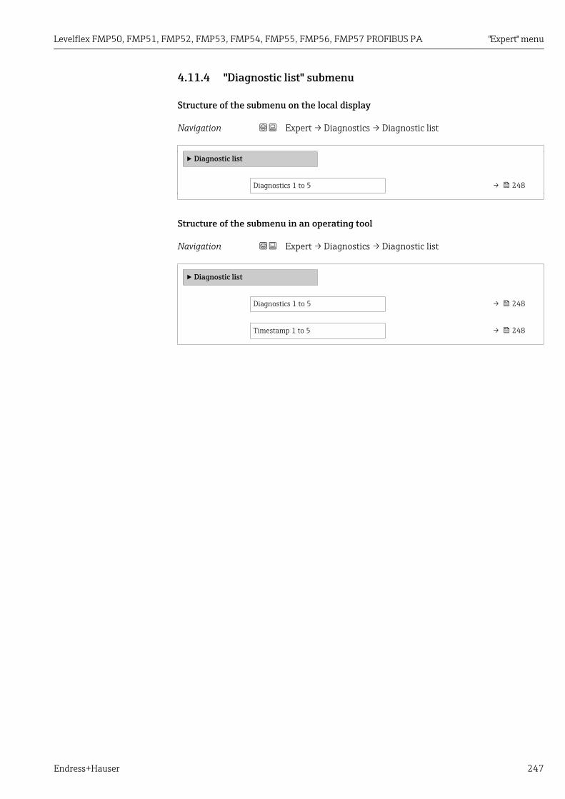
Levelflex FMP50, FMP51, FMP52, FMP53, FMP54, FMP55, FMP56, FMP57 PROFIBUS PA "Expert" menu
Endress+Hauser 247
4.11.4 "Diagnostic list" submenu
Structure of the submenu on the local display
Navigation Expert → Diagnostics → Diagnostic list
‣ Diagnostic list
Diagnostics 1 to 5 → 248
Structure of the submenu in an operating tool
Navigation Expert → Diagnostics → Diagnostic list
‣ Diagnostic list
Diagnostics 1 to 5 → 248
Timestamp 1 to 5 → 248

"Expert" menu Levelflex FMP50, FMP51, FMP52, FMP53, FMP54, FMP55, FMP56, FMP57 PROFIBUS PA
248 Endress+Hauser
Description of parameters
Navigation Expert → Diagnostics → Diagnostic list
Diagnostics 1 to 5
Navigation Expert → Diagnostics → Diagnostic list → Diagnostics 1 to 5 (0692–1 to 5)
Description Display the current diagnostics messages with the highest to fifth-highest priority.
Additional information The display consists of:• Symbol for event behavior• Code for diagnostic behavior• Operating time of occurrence• Event text
Timestamp 1 to 5
Navigation Expert → Diagnostics → Diagnostic list → Timestamp (0683)
Description Displays timestamp for the Diagnostics 1 to 5 parameter (→ 248).
User interface Days (d), hours (h), minutes (m), seconds (s)

Levelflex FMP50, FMP51, FMP52, FMP53, FMP54, FMP55, FMP56, FMP57 PROFIBUS PA "Expert" menu
Endress+Hauser 249
4.11.5 "Event logbook" submenu
Structure of the submenu on the local display
Navigation Expert → Diagnostics → Event logbook
‣ Event logbook
Filter options → 250
‣ Event list
Structure of the submenu in an operating tool
Navigation Expert → Diagnostics → Event logbook
‣ Event logbook

"Expert" menu Levelflex FMP50, FMP51, FMP52, FMP53, FMP54, FMP55, FMP56, FMP57 PROFIBUS PA
250 Endress+Hauser
Description of parameters
Navigation Expert → Diagnostics → Event logbook
Filter options
Navigation Expert → Diagnostics → Event logbook → Filter options (0705)
Description Select category (status signal) whose event messages are displayed in the events list.
Selection • All• Failure (F)• Function check (C)• Out of specification (S)• Maintenance required (M)• Information (I)
Factory setting All
Additional information • This parameter is only used for operation via the local display.• The status signals are categorized according to NAMUR NE 107.

Levelflex FMP50, FMP51, FMP52, FMP53, FMP54, FMP55, FMP56, FMP57 PROFIBUS PA "Expert" menu
Endress+Hauser 251
"Event list" submenuThe Event list submenu displays the history of past events of the category selected in theFilter options parameter (→ 250). A maximum of 20 events are displayed inchronological order. If the advanced HistoROM functionality has been activated in thedevice, the event list may comprise up to 100 entries.
The following symbols indicate whether an event has occurred or has ended:• : Event has occurred• : Event has ended
Information on what is causing the message, and remedy instructions, can be viewedvia the -button.
Display format• For event messages in category I: information event, event text, "recording event" symbol
and time the event occurred• For event messages in category F, M, C, S (status signal): diagnostics event, event text,
"recording event" symbol and time the event occurred

"Expert" menu Levelflex FMP50, FMP51, FMP52, FMP53, FMP54, FMP55, FMP56, FMP57 PROFIBUS PA
252 Endress+Hauser
4.11.6 "Device information" submenu
Structure of the submenu
Navigation Expert → Diagnostics → Device info
‣ Device information
Device tag → 253
Serial number → 253
Firmware version → 253
Device name → 253
Order code → 254
Extended order code 1 to 3 → 254
ENP version → 254
Levelflex FMP50, FMP51, FMP52, FMP53, FMP54, FMP55, FMP56, FMP57 PROFIBUS PA "Expert" menu
Endress+Hauser 253
Description of parameters
Navigation Expert → Diagnostics → Device info
Device tag
Navigation Expert → Diagnostics → Device info → Device tag (0011)
Description Enter the name for the measuring point.
Factory setting FMP5x
Serial number
Navigation Expert → Diagnostics → Device info → Serial number (0009)
Description Displays serial number of the device.
Additional information Uses of the serial number• To identify the device quickly, e.g. when contacting Endress+Hauser.• To obtain specific information on the device using the Device Viewer:
www.endress.com/deviceviewer
The serial number is also indicated on the nameplate.
Firmware version
Navigation Expert → Diagnostics → Device info → Firmware version (0010)
Description Indicates the installed Firmware version.
User interface xx.yy.zz
Additional information For firmware versions differing only in the last two digits ("zz") there is no differenceconcerning functionality or operation.
Device name
Navigation Expert → Diagnostics → Device info → Device name (0013)
Description Displays device name.

"Expert" menu Levelflex FMP50, FMP51, FMP52, FMP53, FMP54, FMP55, FMP56, FMP57 PROFIBUS PA
254 Endress+Hauser
Order code
Navigation Expert → Diagnostics → Device info → Order code (0008)
Description Displays order code of the device.
Additional information The order code is generated from the extended roder code, which defines all devicefeatures of the product structure. In contrast, the device features can not be read directlyfrom the order code.
Extended order code 1 to 3
Navigation Expert → Diagnostics → Device info → Ext. order cd. 1 to 3 (0023–1 to 3)
Description Displays the three parts of the extended order code.
Additional information The extended order code indicates the version of all the features of the product structureand thus uniquely identifies the device.
ENP version
Navigation Expert → Diagnostics → Device info → ENP version (0012)
Description Displays version of the electronic nameplate (ENP).
User interface xx.yy.zz

Levelflex FMP50, FMP51, FMP52, FMP53, FMP54, FMP55, FMP56, FMP57 PROFIBUS PA "Expert" menu
Endress+Hauser 255
4.11.7 "Data logging" submenu
Structure of the submenu on the local display
Navigation Expert → Diagnostics → Data logging
‣ Data logging
Assign channel 1 to 4 → 256
Logging interval → 257
Clear logging data → 257
‣ Display channel 1 to 4
Structure of the submenu in an operating tool
Navigation Expert → Diagnostics → Data logging
‣ Data logging
Assign channel 1 to 4 → 256
Logging interval → 257
Clear logging data → 257

"Expert" menu Levelflex FMP50, FMP51, FMP52, FMP53, FMP54, FMP55, FMP56, FMP57 PROFIBUS PA
256 Endress+Hauser
Description of parameters
Navigation Expert → Diagnostics → Data logging
Assign channel 1 to 4
Navigation Expert → Diagnostics → Data logging → Assign chan. 1 (0851)
Description Allocate a process variable to the respective data logging channel.
Selection • Off• Level linearized• Distance• Unfiltered distance• Interface linearized 17)
• Interface distance 17)
• Unfiltered interface distance• Thickness upper layer 17)
• Terminal voltage• Electronic temperature• Measured capacitance 17)
• Absolute echo amplitude• Relative echo amplitude• Absolute interface amplitude 17)
• Relative interface amplitude 17)
• Absolute EOP amplitude• EOP shift• Noise of signal• Calculated DC value 17)
• Analog output adv. diagnostics 1• Analog output adv. diagnostics 2
Factory setting Off
Additional information A total of 500 measured values can be logged. This means:• 500 data points if 1 logging channel is used• 250 data points if 2 logging channels are used• 166 data points if 3 logging channels are used• 125 data points if 4 logging channels are used
If the maximum number of data points is reached, the oldest data points in the data logare cyclically overwritten in such a way that the last 500, 250, 166 or 125 measuredvalues are always in the log (ring memory principle).
The logged data are deleted if a new option is selected in this parameter.
17) Visibility depends on order options or device settings

Levelflex FMP50, FMP51, FMP52, FMP53, FMP54, FMP55, FMP56, FMP57 PROFIBUS PA "Expert" menu
Endress+Hauser 257
Logging interval
Navigation Expert → Diagnostics → Data logging → Logging interval (0856)
Description Define logging interval tlog.
User entry 1.0 to 3 600.0 s
Factory setting 30.0 s
Additional information This parameter defines the interval between the individual data points in the data log, andthus the maximum loggable process time T log :
• If 1 logging channel is used: T log = 500 ⋅ t log• If 2 logging channels are used: T log = 250 ⋅ t log• If 3 logging channels are used: T log = 166 ⋅ t log• If 4 logging channels are used: T log = 125 ⋅ t log
Once this time elapses, the oldest data points in the data log are cyclically overwritten suchthat a time of T log always remains in the memory (ring memory principle).
The logged data are deleted if this parameter is changed.
Example
When using 1 logging channel• Tlog = 500 ⋅ 1 s = 500 s ≈ 8.5 min• Tlog = 500 ⋅ 10 s = 5 000 s ≈ 1.5 h• Tlog = 500 ⋅ 80 s = 40 000 s ≈ 11 h• Tlog = 500 ⋅ 3 600 s = 1 800 000 s ≈ 20 d
Clear logging data
Navigation Expert → Diagnostics → Data logging → Clear logging (0855)
Description Initiate a deletion of the complete logging memory.
Selection • Cancel• Clear data
Factory setting Cancel

"Expert" menu Levelflex FMP50, FMP51, FMP52, FMP53, FMP54, FMP55, FMP56, FMP57 PROFIBUS PA
258 Endress+Hauser
"Display channel 1 to 4" submenuThe Display channel 1 to 4 submenu is only available when operating via the localdisplay. When operating via FieldCare, the diagram can be displayed in the "EventList / HistoROM" function.
The Display channel 1 to 4 submenu displays the measured value trend of the respectivelogging channel.
• x-axis: displays 125 to 500 measured values of a process variable (the number of valuesdepending on the number of selected channels).
• y-axis: displays the approximate measured value span and constantly adapts this to theongoing measurement.
To quit the diagram and to return to the operating menu, press and simultaneously.

Levelflex FMP50, FMP51, FMP52, FMP53, FMP54, FMP55, FMP56, FMP57 PROFIBUS PA "Expert" menu
Endress+Hauser 259
4.11.8 "Min/max values" submenu
Structure of the submenu
Navigation Expert → Diagnostics → Min/max val.
‣ Min/max values
Max. level value → 260
Time max. level → 260
Min. level value → 260
Time min. level → 260
Max. draining speed → 260
Max. filling speed → 261
Reset min./max. → 261
Max. interface value → 261
Time max. interface → 261
Min. interface value → 262
Time min. interface → 262
I max. drain speed → 262
I max. fill speed → 262
Max. electronics temperature → 262
Time max. electronics temperature → 263
Min. electronics temperature → 263
Time min. electronics temperature → 263
Reset min./max. temp. → 263

"Expert" menu Levelflex FMP50, FMP51, FMP52, FMP53, FMP54, FMP55, FMP56, FMP57 PROFIBUS PA
260 Endress+Hauser
Description of parameters
Navigation Expert → Diagnostics → Min/max val.
Max. level value
Navigation Expert → Diagnostics → Min/max val. → Max. level value (2357)
Description Displays maximum level measured in the past.
Time max. level
Navigation Expert → Diagnostics → Min/max val. → Time max. level (2385)
Description Displays operating time at which the maximum level has been obtained.
Min. level value
Navigation Expert → Diagnostics → Min/max val. → Min. level value (2358)
Description Displays minimum level measured in the past.
Time min. level
Navigation Expert → Diagnostics → Min/max val. → Time min. level (2386)
Description Displays operating time at which the minimum level has been obtained.
Max. draining speed
Navigation Expert → Diagnostics → Min/max val. → Max.drain.speed (2320)
Description Displays maximum draining speed measured in the past.

Levelflex FMP50, FMP51, FMP52, FMP53, FMP54, FMP55, FMP56, FMP57 PROFIBUS PA "Expert" menu
Endress+Hauser 261
Max. filling speed
Navigation Expert → Diagnostics → Min/max val. → Max. fill. speed (2360)
Description Displays maximum filling speed measured in the past.
Reset min./max.
Navigation Expert → Diagnostics → Min/max val. → Reset min/max (2324)
Description Select which min/max values are to be reset.
Selection • None• Drain/fill speed• Level• I drain/fill speed 18)
• Interface 18)
• Reset all
Factory setting None
Max. interface value
Navigation Expert → Diagnostics → Min/max val. → Max.interf.value (2361)
Prerequsite Operating mode (→ 52) = Interface or Interface with capacitance
Description Displays minimum interface height measured in the past.
Time max. interface
Navigation Expert → Diagnostics → Min/max val. → Time max. interf (2388)
Prerequsite Operating mode (→ 52) = Interface or Interface with capacitance
Description Displays operating time at which the maximum interface height has been obtained.
18) Visibility depends on order options or device settings

"Expert" menu Levelflex FMP50, FMP51, FMP52, FMP53, FMP54, FMP55, FMP56, FMP57 PROFIBUS PA
262 Endress+Hauser
Min. interface value
Navigation Expert → Diagnostics → Min/max val. → Min.interf.value (2362)
Prerequsite Operating mode (→ 52) = Interface or Interface with capacitance
Description Displays minimum interface height measured in the past.
Time min. interface
Navigation Expert → Diagnostics → Min/max val. → Time min. interf (2387)
Prerequsite Operating mode (→ 52) = Interface or Interface with capacitance
Description Displays operating time at whicht the minimum interface height has been obtained.
I max. drain speed
Navigation Expert → Diagnostics → Min/max val. → I max. draining (2363)
Prerequsite Operating mode (→ 52) = Interface or Interface with capacitance
Description Displays maximum drainging speed of the lower medium measured in the past.
I max. fill speed
Navigation Expert → Diagnostics → Min/max val. → I max.fill speed (2359)
Prerequsite Operating mode (→ 52) = Interface or Interface with capacitance
Description Displays maximum filling speed of the lower medium measured in the past.
Max. electronics temperature
Navigation Expert → Diagnostics → Min/max val. → Max.electr.temp. (1031)
Description Displays maximum electronics temperature measured in the past.

Levelflex FMP50, FMP51, FMP52, FMP53, FMP54, FMP55, FMP56, FMP57 PROFIBUS PA "Expert" menu
Endress+Hauser 263
Time max. electronics temperature
Navigation Expert → Diagnostics → Min/max val. → Time max.el.temp (1204)
Description Displays operating time at which the maximum electronics temperature has beenobtained.
Min. electronics temperature
Navigation Expert → Diagnostics → Min/max val. → Min.electr.temp. (1040)
Description Displays minimum electronics temperature measured in the past.
Time min. electronics temperature
Navigation Expert → Diagnostics → Min/max val. → Time min.el.temp (1205)
Description Displays operating time at which the minimum electronics temperature has been obtained.
Reset min./max. temp.
Navigation Expert → Diagnostics → Min/max val. → Res.min/max temp (1173)
Description Select which min/max values are to be reset.
User interface • None• Electronic temperature• Reset all
Factory setting None

"Expert" menu Levelflex FMP50, FMP51, FMP52, FMP53, FMP54, FMP55, FMP56, FMP57 PROFIBUS PA
264 Endress+Hauser
4.11.9 "Simulation" submenuThe Simulation submenu is used to simulate specific measuring values or otherconditions. This helps to check the correct configuration of the device and connectedcontrol units.
Conditions which can be simulated
Condition to be simulated Associated parameters
Specific value of a process variable • Assign measurement variable (→ 266)• Value process variable (→ 266)
Specific state of the switch output • Switch output simulation (→ 266)• Switch status (→ 267)
Existence of an alarm Simulation device alarm (→ 267)

Levelflex FMP50, FMP51, FMP52, FMP53, FMP54, FMP55, FMP56, FMP57 PROFIBUS PA "Expert" menu
Endress+Hauser 265
Structure of the submenu
Navigation Expert → Diagnostics → Simulation
‣ Simulation
Assign measurement variable → 266
Value process variable → 266
Switch output simulation → 266
Switch status → 267
Simulation device alarm → 267

"Expert" menu Levelflex FMP50, FMP51, FMP52, FMP53, FMP54, FMP55, FMP56, FMP57 PROFIBUS PA
266 Endress+Hauser
Description of parameters
Navigation Expert → Diagnostics → Simulation
Assign measurement variable
Navigation Expert → Diagnostics → Simulation → Assign meas.var. (2328)
Description Selct process variable to be simulated.
Selection • Off• Level• Interface 19)
• Level linearized• Interface linearized• Thickness linearized
Factory setting Off
Additional information • The value of the variable to be simulated is defined in the Value process variableparameter (→ 266).
• If Assign measurement variable ≠ Off, a simulation is active. This is indicated by adiagnotic message of the Function check (C) category.
Value process variable
Navigation Expert → Diagnostics → Simulation → Value proc. var. (2329)
Prerequsite Assign measurement variable (→ 266) ≠ Off
Description Specify value of the process value being simulated.
User entry Signed floating-point number
Factory setting 0
Additional information Downstream measured value processing and the signal output use this simulation value. Inthis way, users can verify whether the measuring device has been configured correctly.
Switch output simulation
Navigation Expert → Diagnostics → Simulation → Switch sim. (0462)
Description Switch the simulation of the switch output on or off.
19) Visibility depends on order options or device settings

Levelflex FMP50, FMP51, FMP52, FMP53, FMP54, FMP55, FMP56, FMP57 PROFIBUS PA "Expert" menu
Endress+Hauser 267
Selection • Off• On
Factory setting Off
Switch status
Navigation Expert → Diagnostics → Simulation → Switch status (0463)
Prerequsite Switch output simulation (→ 266) = On
Description Define the switch state to be simulated.
Selection • Open• Closed
Factory setting Open
Additional information The switch status assumes the value defined in this parameter. This helps to check correctoperation of connected control units.
Simulation device alarm
Navigation Expert → Diagnostics → Simulation → Sim. alarm (0654)
Description Switch alarm simulation on or off.
Selection • Off• On
Factory setting Off
Additional information When selecting the On option, the device generates an alarm. This helps to check thecorrect output behavior of the device in the case of an alarm.
An active simulation is indicated by the diagnostic message C484 Simulation failuremode.

"Expert" menu Levelflex FMP50, FMP51, FMP52, FMP53, FMP54, FMP55, FMP56, FMP57 PROFIBUS PA
268 Endress+Hauser
4.11.10 "Device check" submenu
Structure of the submenu
Navigation Expert → Diagnostics → Device check
‣ Device check
Start device check → 269
Result device check → 269
Last check time → 269
Level signal → 270
Launch signal → 270
Interface signal → 270

Levelflex FMP50, FMP51, FMP52, FMP53, FMP54, FMP55, FMP56, FMP57 PROFIBUS PA "Expert" menu
Endress+Hauser 269
Description of parameters
Navigation Expert → Diagnostics → Device check
Start device check
Navigation Expert → Diagnostics → Device check → Start dev. check (1013)
Description Start a device check.
Selection • No• Yes
Factory setting No
Additional information In the case of a lost echo a device check can not be performed.
Result device check
Navigation Expert → Diagnostics → Device check → Result dev.check (1014)
Description Displays the result of the device check.
Additional information Meaning of the display options• Installation ok
Measurement possible without restrictions.• Accuracy reduced
A measurement is possible. However, the measuring accuracy may be reduced due to thesignal amplitudes.
• Measurement capability reducedA measurement is currently possible. Howerver, there is the risk of an echo loss. Checkthe mounting position of the device and the dielectric constant of the medium.
• Check not doneNo device check has been performed.
Last check time
Navigation Expert → Diagnostics → Device check → Last check time (1203)
Description Displays the operating time at which the last device check has been performed.

"Expert" menu Levelflex FMP50, FMP51, FMP52, FMP53, FMP54, FMP55, FMP56, FMP57 PROFIBUS PA
270 Endress+Hauser
Level signal
Navigation Expert → Diagnostics → Device check → Level signal (1016)
Prerequsite Device check has been performed.
Description Displays result of the device check for the level signal.
User interface • Check not done• Check not OK• Check OK
Additional information For Level signal = Check not OK: Check the mounting position of the device and thedielectric constant of the medium.
Launch signal
Navigation Expert → Diagnostics → Device check → Launch signal (1012)
Prerequsite Device check has been performed.
Description Displays result of the display check for the launch signal.
User interface • Check not done• Check not OK• Check OK
Additional information For Launch signal = Check not OK: Check the mounting position of the device. In non-metallic vessels use a metal plate or a metal flange.
Interface signal
Navigation Expert → Diagnostics → Device check → Interface signal (1015)
Prerequsite • Operating mode (→ 52) = Interface or Interface with capacitance• Device check has been performed.
Description Displays result of the device check for the interface signal.
User interface • Check not done• Check not OK• Check OK
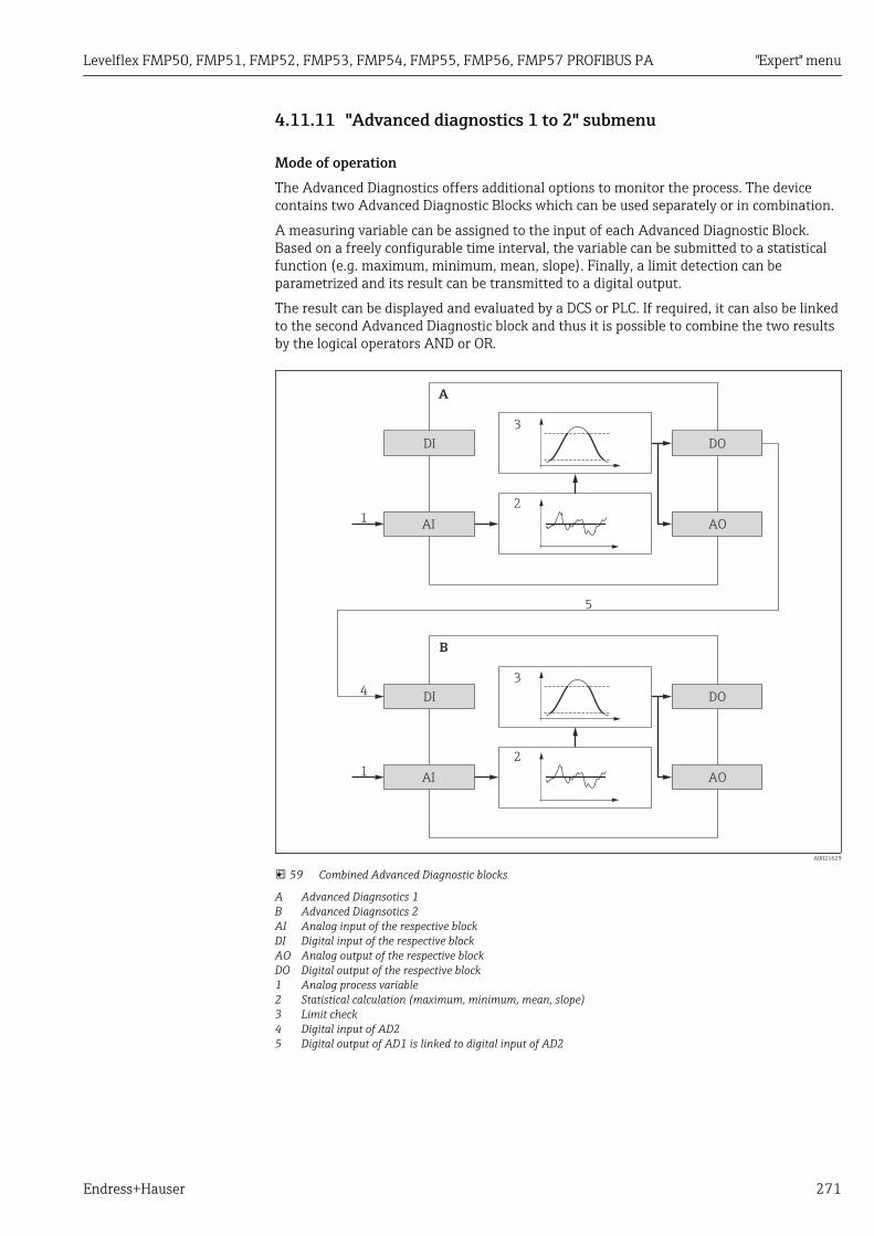
Levelflex FMP50, FMP51, FMP52, FMP53, FMP54, FMP55, FMP56, FMP57 PROFIBUS PA "Expert" menu
Endress+Hauser 271
4.11.11 "Advanced diagnostics 1 to 2" submenu
Mode of operationThe Advanced Diagnostics offers additional options to monitor the process. The devicecontains two Advanced Diagnostic Blocks which can be used separately or in combination.
A measuring variable can be assigned to the input of each Advanced Diagnostic Block.Based on a freely configurable time interval, the variable can be submitted to a statisticalfunction (e.g. maximum, minimum, mean, slope). Finally, a limit detection can beparametrized and its result can be transmitted to a digital output.
The result can be displayed and evaluated by a DCS or PLC. If required, it can also be linkedto the second Advanced Diagnostic block and thus it is possible to combine the two resultsby the logical operators AND or OR.
1
1
4
5
A
B
DI
DI
2
2
AI
AI
3
3
AO
AO
DO
DO
A0021629
59 Combined Advanced Diagnostic blocks
A Advanced Diagnsotics 1B Advanced Diagnsotics 2AI Analog input of the respective blockDI Digital input of the respective blockAO Analog output of the respective blockDO Digital output of the respective block1 Analog process variable2 Statistical calculation (maximum, minimum, mean, slope)3 Limit check4 Digital input of AD25 Digital output of AD1 is linked to digital input of AD2

"Expert" menu Levelflex FMP50, FMP51, FMP52, FMP53, FMP54, FMP55, FMP56, FMP57 PROFIBUS PA
272 Endress+Hauser
Overview of the Advanced Diagnostic functionalities
Task Associated parameters
Allocation of a process variable to the analog input of theblock.
Assign diagnostic signal (→ 279)
Linking the digital input to the digital output of the otherblock.
• Link AD to (→ 279)• Linking logic AD (→ 280)
Calculation of one of the following quantities for a freelyconfigurable sampling interval:• Maximum• Minimum• Mean• Standard deviation• Difference Max. - Min.• Slope
• Sample time (→ 280)• Calculation type (→ 280)• Calculation unit (→ 282)
Drag indicator for the calculated quantity • Maximum value (→ 284)• Minimum value (→ 284)• Reset min./max. (→ 285)
Limit check • Check mode (→ 281)• Upper limit (→ 283)• Lower limit (→ 283)• Hysteresis (→ 284)
Reaction in case of a limit violation • Assign status signal to AD event (→ 285)• Assign event behaviour (→ 285)• Alarm delay (→ 286)

Levelflex FMP50, FMP51, FMP52, FMP53, FMP54, FMP55, FMP56, FMP57 PROFIBUS PA "Expert" menu
Endress+Hauser 273
Example 1: Draining/filling speedOnly one Advanced Diagnostic Block is needed for this application. In the example thisis Advanced diagnostics 1 (→ 278). However, Advanced diagnostics 2(→ 278) could be used just as well.
The level change rate (i.e. draining or filling speed) allows the customer to instantly realizewhether or not the level is changing, and at which rate. The rate at which the level ischanging must be observed as powerful pumps can create significant over andunderpressure in a tank. Pressure relieve valves can only operate properly up to a certainlevel change rate. This is in particular valid for almost emptied tanks. The level change rateis also an intermediate result for calculating transfer estimates, such as time to fill, time toempty, time to target, etc.
Basic idea
The Advanced Diagnostics is used to calculate the draining or filling speed from themeasured level. The result can be transmitted via the current output or the HARTcommunication interface.
1
AD1
2
3
AI AO
a a a
D
D
L
t
D
D
L
tL
A0022315
60 Calculation of the draining or filling speed
1 Allocation of the (linearized) level to Advanced Diagnsotic Block AD12 Calculation of the draining or filling speed ΔL/Δt within the sampling interval a.3 ΔL/Δt can be transmitted via the current output or the HART communication interface.
Configuration of the calculation
The calculation of the rate of level change is configured as follows:
1. Select Assign diagnostic signal 1 = Level linearized.
2. Select Link AD 1 to = None (= factory setting)
3. Define Sample time 1 in accordance with the expected draining or filling speed.
4. Select Calculation type 1 = Slope.
5. Select a suitable option in Calculation unit 1, e.g.: "Level unit" / s
As the rate of level change is not to be checked for limit violation, the followingparameters may retain their factory settings:• Check mode 1• Assign status signal to AD event (→ 285)• Assign event behaviour (→ 285)• Alarm delay (→ 286)With this configuration, the Maximum value 1 and Minimum value 1 dragindicators display the maximum or minimum value the rate of lavel change hasobtained. Positive values indicate filling (rising level), negative values indicatedraining (falling level). If required, the drag indicators can be reset by the Reset min./max. 1 parameter.

"Expert" menu Levelflex FMP50, FMP51, FMP52, FMP53, FMP54, FMP55, FMP56, FMP57 PROFIBUS PA
274 Endress+Hauser
Allocation of the calculated rate of level change to the current output
1. Navigate to the following submenu: Expert → Output → Curr.output 1.
2. Select Assign current output = Analog output adv. diagnostics 1.
3. Select Turn down = On.
4. Enter maximum expected draining speed (negative value) in 4 mA value.
5. Enter maximum expected filling speed (positive value) in 20 mA value.
With this configuration, the rate of level change is transmitted via the current output. Therelationship between the rate of level change and the output current is as follows:
5W - W4 20DL
Dt
W - W20 4
4 16 mAI+=
A0022342
Where:• ΔL/Δt : Rate of level change 20)
• W4 : 4 mA value• W20 : 20 mA value• I: Output current
In the case of a constant level (ΔL/Δt = 0) the current is:
W - W20 4
W4
4 mA 16 mAI0
-=
A0022343
Allocation of the calculated rate of level change to the HART output
1. Navigate to the following submenu: Expert → Communication → Output
2. Select Assign PV = Analog output adv. diagnostics 1.
With this configuration, the Primary variable (PV) parameter displays the calculatedfilling or draining speed. Positive values indicate filling; negative values indicatedraining.
Instead of PV, it is also possible to allocate the rate of level change to SV, TV or QV.
20) Negative values: draining speed; Positive values: filling speed

Levelflex FMP50, FMP51, FMP52, FMP53, FMP54, FMP55, FMP56, FMP57 PROFIBUS PA "Expert" menu
Endress+Hauser 275
Example 2: Foam detectionIn this example, both Advance Diagnostic Blocks are used.
Preconditions
• The process runs at a fixed level (in the example: 80 %)• If foam occurs during the operation, the vessel should automatically be sprinkled with
water from the top or an antifoam agent should be added to dissolve the foam.
Basic idea
The echo amplitude decreases in the case of foam formation. This can be used by theAdvanced Diagnostics to detect the foam. The foam detection, however, should only beactive as long as the level is between 75 % and 85 %.
85%
75%
A A
A0022594
61 Decrease of the amplitude in case of foam formation
A Amplitude threshold for foam detection
Configuration of the level monitoring
In order to ensure that the level is within the correct range, configure the Advanceddiagnostics 1 submenu (→ 278) submenu as follows:
1. Navigate to the Advanced diagnostics 1 submenu (→ 278)
2. Select Assign diagnostic signal 1 = Level linearized.
3. Select Check mode 1 = Out of range4. Set Upper limit 1 = 85 %.
5. Set Lower limit 1 = 75 %.
Check mode 1 = Out of range checks whether the level is outside a defined range. Aslong as this is the case, the block outputs "0" (INACTIVE). If the level gets into thedefined range, the block outputs "1" (ACTIVE).
Configuration of the foam detection
For the foam detection, configure the Advanced diagnostics 2 submenu (→ 278) asfollows:

"Expert" menu Levelflex FMP50, FMP51, FMP52, FMP53, FMP54, FMP55, FMP56, FMP57 PROFIBUS PA
276 Endress+Hauser
1. Select Assign diagnostic signal 2 = Relative echo amplitude.
2. Use the Minimum value 2 parameter to observe the echo amplitude for the specifiedlevel (80 % in the example) for a while and determine a suitable lower limit for theamplitude (130 mV in the example).
3. Select Calculation type 2 = Mean.
4. Enter Sample time 2 = "60 s".
5. Select Check mode 2 = Lower limit.
6. Enter the amplitude limit determined in step 2 into the Lower limit 2 parameter(130 mV in the example).
With these settings, the Advanced Diagnostic Block behaves as follows:• If the amplitude is above 130 mV (i.e.: no foam), the block assumes the digital value
"0" (INACTIVE).• If the amplitude is below 130 mV (i.e.: foam present), the block assumes the digital
value "1" (ACTIVE).
Configuration of the block linking
The linking logic is configured in the Advanced diagnostics 2 submenu (→ 278):
1. Select Link AD 2 to = Digital output AD 1.
2. Select Linking logic AD 2 = AND.
With this configuration the output of Advanced Diagnostics 2 assumes the followingvalue:• 0 (INACTIVE) - if at least one of the two blocks is in the "0" (INACTIVE) status.• 1 (ACTIVE) - if both blocks are in the "1" (ACTIVE) status.
For the example this means:– A diagnostic signal is output, if the level is within the defined range and the signal
amplitude is below the threshold (i.e. foam is present).– If, on the other hand, the level is out of the defined range or if the signal
amplitude exceeds the threshold (i.e. no foam), no diagnostic signal istransmitted via the switch output.
The digital output signal of Advanced diagnostics 2 can be linked to the switchoutput of the device:
Expert → Output → Switch output → Assign status (0485) = Digital output AD 2

Levelflex FMP50, FMP51, FMP52, FMP53, FMP54, FMP55, FMP56, FMP57 PROFIBUS PA "Expert" menu
Endress+Hauser 277
Overview: Foam detection with the advanced diagnostics
L
L
A
1.1
2.1
1.3
1.2
2.2 2.4
2.5
2.7
2.6
2.8
2.3
1.5
1.4
A
1
2
A0022595
62 Configuration of the Advanced Diagnostics for foam detection
L LevelA Amplitude1 Advanced diagnostics 1: Monitoring the level1.1 "Assign diagnostic signal 1" = "Relative echo amplitude"1.2 "Check mode 1" = "Out of range"1.3 "Upper limit 1" = 85 %1.4 "Lower limit 1" = 75 %1.5 Digital output of Advanced Diagnostics 12 Advanced Diagnostics 2: Monitoring the amplitude2.1 "Assign diagnostic signal 2" = "Relative echo amplitude"2.2 "Calculation type 2" = "Mean"2.3 "Sample time 2" = 60 s2.4 "Check mode 2" = "Lower limit"2.5 "Lower limit 2" = 130 mV2.6 "Link AD 2 to" = "Digital output AD 1"2.7 "Linking logic AD 2" = "AND"2.8 Digital output of Advanced Diagnostics 2

"Expert" menu Levelflex FMP50, FMP51, FMP52, FMP53, FMP54, FMP55, FMP56, FMP57 PROFIBUS PA
278 Endress+Hauser
Structure of the submenu
Navigation Expert → Diagnostics → Adv.diagn. 1 to 2
‣ Advanced diagnostics 1 to 2
Assign diagnostic signal 1 to 2 → 279
Link AD 1 to 2 to → 279
Linking logic AD 1 to 2 → 280
Sample time 1 to 2 → 280
Calculation type 1 to 2 → 280
Check mode 1 to 2 → 281
Calculation unit 1 to 2 → 282
Upper limit 1 to 2 → 283
Lower limit 1 to 2 → 283
Hysteresis 1 to 2 → 284
Value → 284
Maximum value 1 to 2 → 284
Minimum value 1 to 2 → 284
Reset min./max. 1 to 2 → 285
Assign status signal to AD event 1 to 2 → 285
Assign event behaviour 1 to 2 → 285
Alarm delay 1 to 2 → 286
Levelflex FMP50, FMP51, FMP52, FMP53, FMP54, FMP55, FMP56, FMP57 PROFIBUS PA "Expert" menu
Endress+Hauser 279
Description of parameters
Navigation Expert → Diagnostics → Adv.diagn. 1 to 2
Assign diagnostic signal 1 to 2
Navigation Expert → Diagnostics → Adv.diagn. 1 to 2 → Assign signal 1 to 2 (11179–1 to 2)
Description Allocate a measuring variable to the Advanced Diagnostic Block.
Selection • None• Level linearized• Interface linearized 21)
• Thickness upper layer 21)
• Distance• Unfiltered distance• Interface distance 21)
• Unfiltered interface distance• Absolute echo amplitude• Relative echo amplitude• Absolute interface amplitude 21)
• Relative interface amplitude 21)
• Absolute EOP amplitude• EOP shift• Sensor debug• Noise of signal• Measured capacitance 21)
• Electronic temperature• Terminal voltage• Calculated DC value 21)
• Analog output 1• Analog output 2• Analog output 3• Analog output 4
Factory setting None
Link AD 1 to 2 to
Navigation Expert → Diagnostics → Adv.diagn. 1 to 2 → Link AD 1 to 2 to (11180–1 to 2)
Description Link the digital input (DI) of the Advanced Diagnostic Block to the digital output (DO) ofthe other Advanced Diagnostic Block.
Selection • None• Digital output AD 1• Digital output AD 2• Digital output 1
21) Visibility depends on order options or device settings

"Expert" menu Levelflex FMP50, FMP51, FMP52, FMP53, FMP54, FMP55, FMP56, FMP57 PROFIBUS PA
280 Endress+Hauser
• Digital output 2• Digital output 3• Digital output 4
Factory setting None
Linking logic AD 1 to 2
Navigation Expert → Diagnostics → Adv.diagn. 1 to 2 → Link. logic AD 1 to 2 (11181–1 to 2)
Prerequsite Link AD to (→ 279) = Digital output AD 1 oder Digital output AD 2
Description Select linking logic between the two Advanced Diagnostic Blocks.
Selection • AND• OR
Factory setting AND
Sample time 1 to 2
Navigation Expert → Diagnostics → Adv.diagn. 1 to 2 → Sample time 1 to 2 (11187–1 to 2)
Prerequsite Assign diagnostic signal (→ 279) ≠ None
Description Specify sampling interval for the calculation.
User entry 1 to 3 600 s
Factory setting 10 s
Calculation type 1 to 2
Navigation Expert → Diagnostics → Adv.diagn. 1 to 2 → Calc. type 1 to 2 (11174–1 to 2)
Prerequsite Assign diagnostic signal (→ 279) ≠ None
Description Select quantity to be calculated from the measured variable.
Selection • Off• Maximum• Minimum• Mean• Standard deviation• Difference Max. - Min.• Slope

Levelflex FMP50, FMP51, FMP52, FMP53, FMP54, FMP55, FMP56, FMP57 PROFIBUS PA "Expert" menu
Endress+Hauser 281
Factory setting Off
Additional informationa
a
a
a
a
a
A
B
C
F
D
E
a
a
a
a
a
a
a
a
a
a
a
a
D
D
y
x
A0021630
63 Options of the "Calculation type " parameter
a Sample time (→ 280)A "Calculation type " = "Maximum"B "Calculation type " = "Minimum"C "Calculation type " = "Mean"D "Calculation type " = "Standard deviation"E "Calculation type " = "Difference Max. - Min."F "Calculation type " = "Slope"
The calculation is performed based on the sampling interval defined in the Sampletime parameter (→ 280).
Check mode 1 to 2
Navigation Expert → Diagnostics → Adv.diagn. 1 to 2 → Check mode 1 to 2 (11175–1 to 2)
Prerequsite Assign diagnostic signal (→ 279) ≠ None
Description Define check mode for limit monitoring.

"Expert" menu Levelflex FMP50, FMP51, FMP52, FMP53, FMP54, FMP55, FMP56, FMP57 PROFIBUS PA
282 Endress+Hauser
Selection • Off• Upper limit• Lower limit• In range• Out of range
Factory setting Off
Additional information
B
A
D
C
1
a
b
a
b
b
a
1
1
1
0
0
0
0
c c
c
c
c
c
A0021631
64 Limit monitoring in the Advanced Diagnostic Block
0 Status of digital output: 0 ("INACTIVE")1 Status of digital output: 1 ("ACTIVE")a Upper limit (→ 283)b Lower limit (→ 283)c Hysteresis (→ 284)A "Check mode " = "Lower limit"B "Check mode " = "Upper limit"C "Check mode " = "In range"D "Check mode " = "Out of range"
If a calculation has been selected in the Calculation type parameter (→ 280), thecheck does not refer to the assigned measuring variable but to the quantity calculatedfrom it.
Calculation unit 1 to 2
Navigation Expert → Diagnostics → Adv.diagn. 1 to 2 → Calc. unit 1 to 2 (11188–1 to 2)
Prerequsite Assign diagnostic signal (→ 279) ≠ None
Description Select unit for the calculation.
Selection Dependent on the following parameters:• Assign diagnostic signal (→ 279)• Calculation type (→ 280)

Levelflex FMP50, FMP51, FMP52, FMP53, FMP54, FMP55, FMP56, FMP57 PROFIBUS PA "Expert" menu
Endress+Hauser 283
Factory setting Dependent on the following parameters:• Assign diagnostic signal (→ 279)• Calculation type (→ 280)
Upper limit 1 to 2
Navigation Expert → Diagnostics → Adv.diagn. 1 to 2 → Upper limit 1 to 2 (11182–1 to 2)
Prerequsite Check mode parameter (→ 281) has one of the following values:• Upper limit• In range• Out of range
Description Specify upper limit for the limit monitoring.
User entry Dependent on the following parameters:• Assign diagnostic signal (→ 279)• Calculation type (→ 280)
Factory setting Dependent on the following parameters:• Assign diagnostic signal (→ 279)• Calculation type (→ 280)
Lower limit 1 to 2
Navigation Expert → Diagnostics → Adv.diagn. 1 to 2 → Lower limit 1 to 2 (11184–1 to 2)
Prerequsite Check mode parameter (→ 281) has one of the following values:• Lower limit• In range• Out of range
Description Define lower limit for the limit monitoring.
User entry Dependent on the following parameters:• Assign diagnostic signal (→ 279)• Calculation type (→ 280)
Factory setting Dependent on the following parameters:• Assign diagnostic signal (→ 279)• Calculation type (→ 280)

"Expert" menu Levelflex FMP50, FMP51, FMP52, FMP53, FMP54, FMP55, FMP56, FMP57 PROFIBUS PA
284 Endress+Hauser
Hysteresis 1 to 2
Navigation Expert → Diagnostics → Adv.diagn. 1 to 2 → Hysteresis 1 to 2 (11178–1 to 2)
Prerequsite Check mode parameter (→ 281) has one of the following values:• Upper limit• Lower limit• In range• Out of range
Description Select hysteresis for the limit monitoring.
User entry Dependent on the following parameters:• Assign diagnostic signal (→ 279)• Calculation type (→ 280)
Factory setting Dependent on the following parameters:• Assign diagnostic signal (→ 279)• Calculation type (→ 280)
Value
Navigation Expert → Diagnostics → Adv.diagn. 1 to 2 → Value (11172–1 to 2)
Description Displays the current value of the calculated process variable.
Maximum value 1 to 2
Navigation Expert → Diagnostics → Adv.diagn. 1 to 2 → Maximum value 1 to 2 (11183–1 to 2)
Prerequsite Assign diagnostic signal (→ 279) ≠ None
Description Indicates the maximum value the assigned measuring variable has obtained in the past(drag indicator).
Minimum value 1 to 2
Navigation Expert → Diagnostics → Adv.diagn. 1 to 2 → Minimum value 1 to 2 (11185–1 to 2)
Prerequsite Assign diagnostic signal (→ 279) ≠ None
Description Indicates minimum value the assigned measuring variable has obtained in the past (dragindicator).

Levelflex FMP50, FMP51, FMP52, FMP53, FMP54, FMP55, FMP56, FMP57 PROFIBUS PA "Expert" menu
Endress+Hauser 285
Reset min./max. 1 to 2
Navigation Expert → Diagnostics → Adv.diagn. 1 to 2 → Reset min/max 1 to 2 (11186–1 to 2)
Prerequsite Assign diagnostic signal (→ 279) ≠ None
Description Reset drag indicators (Maximum value (→ 284) and/or Minimum value (→ 284)).
Selection • Off• Reset max.• Reset min.• Reset min./max.
Factory setting Off
Assign status signal to AD event 1 to 2
Navigation Expert → Diagnostics → Adv.diagn. 1 to 2 → Stat. AD event 1 to 2 (11176–1 to 2)
Prerequsite Assign diagnostic signal (→ 279) ≠ None
Description Assign a category according to NAMUR NE107 to the event of the Advanced DiagnosticBlock.
Selection • Failure (F)• Maintenance required (M)• Function check (C)• Out of specification (S)
Factory setting Maintenance required (M)
Assign event behaviour 1 to 2
Navigation Expert → Diagnostics → Adv.diagn. 1 to 2 → Evt behaviour 1 to 2 (11177–1 to 2)
Prerequsite Assign diagnostic signal (→ 279) ≠ None
Description Assign an event behavior to the event of the Advanced Diagnostic Block.
Selection • Off• Alarm• Warning• Logbook entry only
Factory setting Warning

"Expert" menu Levelflex FMP50, FMP51, FMP52, FMP53, FMP54, FMP55, FMP56, FMP57 PROFIBUS PA
286 Endress+Hauser
Alarm delay 1 to 2
Navigation Expert → Diagnostics → Adv.diagn. 1 to 2 → Alarm delay 1 to 2 (11171–1 to 2)
Prerequsite Assign diagnostic signal (→ 279) ≠ None
Description Define alarm delay for the Advanced Diagnostic Block.
User entry 0.0 to 3 600.0 s
Factory setting 10.0 s

Levelflex FMP50, FMP51, FMP52, FMP53, FMP54, FMP55, FMP56, FMP57 PROFIBUS PA "Expert" menu
Endress+Hauser 287
4.11.12 "Envelope diagnostics" submenuIn devices which have been delivered with software version 01.00.zz, this submenu isonly visible for the "Service" user role.
After the configuration of the measurement it is recommended to record the currentenvelope curve as a reference curve. The reference curve can be used later for diagnosticpurposes. To record the reference curve use the Save reference curve parameter(→ 288).
The reference curve can only be displayed in the envelope curve diagram of FieldCare afterit has been loaded from the device into FieldCare. This is performed by the "Load ReferenceCurve" function in FieldCare:
Structure of the submenu
Navigation Expert → Diagnostics → Envelope diag.
‣ Envelope diagnostics
Save reference curve → 288
Time reference curve → 288

"Expert" menu Levelflex FMP50, FMP51, FMP52, FMP53, FMP54, FMP55, FMP56, FMP57 PROFIBUS PA
288 Endress+Hauser
Description of parameters
Navigation Expert → Diagnostics → Envelope diag.
Save reference curve
Navigation Expert → Diagnostics → Envelope diag. → Save ref. curve (1218)
Description Save current envelope curve as reference curve.
Selection • No• Yes
Factory setting No
Additional information Meaning of the options• No
No action• Yes
The current envelope curve is saved as reference curve.
Time reference curve
Navigation Expert → Diagnostics → Envelope diag. → Time ref. curve (1232)
Description Indicates at which time the existing reference curve has been recorded.
Levelflex FMP50, FMP51, FMP52, FMP53, FMP54, FMP55, FMP56, FMP57 PROFIBUS PA Index
Endress+Hauser 289
Index
AAbsolute echo amplitude (Parameter) . . . . . . . . . . . . 86Absolute EOP amplitude (Parameter) . . . . . . . . . . . . . 89Absolute interface amplitude (Parameter) . . . . . . . . . 88Access status display (Parameter) . . . . . . . . . . . . 30, 40Access status tooling (Parameter) . . . . . . . . . . . . . . . 30Acknowledge alarm (Parameter) . . . . . . . . . . . . . . . 128Activate SW option (Parameter) . . . . . . . . . . . . . . . . 47Activate table (Parameter) . . . . . . . . . . . . . . . . . . . . . 83Actual diagnostics (Parameter) . . . . . . . . . . . . . . . . 245Address mode (Parameter) . . . . . . . . . . . . . . . . . . . 175Administration (Submenu) . . . . . . . . . . . . . . . . . 46, 47Advanced diagnostics 1 to 2 (Submenu) . . . . . . 278, 279Advanced process conditions (Parameter) . . . . . . . . . 55Alarm delay 1 to 2 (Parameter) . . . . . . . . . . . . . . . . 286Alarm hysteresis (Parameter) . . . . . . . . . . . . . . . . . 199Alarm summary (Parameter) . . 183, 193, 210, 221, 235Alert key (Parameter) . . . . . . . 182, 191, 208, 219, 233Analog input 1 to 6 (Submenu) . . . . . . . . . . . . 189, 191Analog output 1 to 4 (Submenu) . . . . . . . . . . . 217, 219Application parameter (Parameter) . . . . . . . . . . . . . . 56Assign channel 1 (Parameter) . . . . . . . . . . . . . . . . . 256Assign diagnostic behavior (Parameter) . . . . . . . . . . 167Assign diagnostic signal 1 to 2 (Parameter) . . . . . . . 279Assign event behaviour 1 to 2 (Parameter) . . . . . . . . 285Assign limit (Parameter) . . . . . . . . . . . . . . . . . . . . . 168Assign measurement variable (Parameter) . . . . . . . . 266Assign status (Parameter) . . . . . . . . . . . . . . . . . . . . 170Assign status signal to AD event 1 to 2 (Parameter) 285
BBacklight (Parameter) . . . . . . . . . . . . . . . . . . . . . . . . 39Backup state (Parameter) . . . . . . . . . . . . . . . . . . . . . 44Base current (Parameter) . . . . . . . . . . . . . . . . . . . . 179Batch ID (Parameter) . . . . . . . . . . . . 193, 210, 221, 235Batch operation (Parameter) . . . . . . 193, 210, 221, 235Batch phase (Parameter) . . . . . . . . . 193, 210, 222, 236Batch Recipe Unit Procedure (Parameter) 194, 211,222, 236Bin type (Parameter) . . . . . . . . . . . . . . . . . . . . . . . . . 53Blocking distance (Parameter) . . . . . . . . . . . . . . . . . 102Broken probe detection (Parameter) . . . . . . . . . . . . 117Build-up ratio (Parameter) . . . . . . . . . . . . . . . . . . . . 163Build-up thres. (Parameter) . . . . . . . . . . . . . . . . . . . 163
CCalculated DC value (Parameter) . . . . . . . . . . . . 61, 145Calculation type 1 to 2 (Parameter) . . . . . . . . . . . . . 280Calculation unit 1 to 2 (Parameter) . . . . . . . . . . . . . 282Channel (Parameter) . . . . . . . . . . . . . . . . . . . . 196, 212Check mode 1 to 2 (Parameter) . . . . . . . . . . . . . . . . 281Clear logging data (Parameter) . . . . . . . . . . . . . . . . 257Communication (Submenu) . . . . . . . . . . . . . . . . . . . 173Comparison result (Parameter) . . . . . . . . . . . . . . . . . 44Condensed status diagnostic (Parameter) . . . . . . . . . 187Configuration backup display (Submenu) . . . . . . . 42, 43
Configuration management (Parameter) . . . . . . . . . . 43Confirm access code (Parameter) . . . . . . . . . . . . . . . . 49Confirm distance (Parameter) . . . . . . . . . . . . . . . . . 138Confirm probe length (Parameter) . . . . . . . . . . . . . . . 94Const. GPC factor (Parameter) . . . . . . . . . . . . . . . . . 113Contrast display (Parameter) . . . . . . . . . . . . . . . . . . . 39CRC Count Failed (Parameter) . . . . . . . . . . . . . . . . . 178CRC Count OK (Parameter) . . . . . . . . . . . . . . . . . . . 178Customer value (Parameter) . . . . . . . . . . . . . . . . . . . 83
DData logging (Submenu) . . . . . . . . . . . . . . . . . 255, 256DC value (Parameter) . . . . . . . . . . . . . . . . . . . . 60, 144DC value lower medium (Parameter) . . . . . . . . . . . . . 59Dead time (Parameter) . . . . . . . . . . . . . . . . . . . . . . 100Decimal places 1 to 4 (Parameter) . . . . . . . . . . . . . . . 36Decimal places menu (Parameter) . . . . . . . . . . . . . . . 39Define access code (Parameter) . . . . . . . . . . . . . . 47, 49Define access code (Wizard) . . . . . . . . . . . . . . . . . . . 49Delay time echo lost (Parameter) . . . . . . . . . . . . . . . 126Descriptor (Parameter) . . . . . . . . . . . . . . . . . . . . . . 185Device address (Parameter) . . . . . . . . . . . . . . . . . . . 176Device certification (Parameter) . . . . . . . . . . . . . . . . 185Device check (Submenu) . . . . . . . . . . . . . . . . . 268, 269Device ID (Parameter) . . . . . . . . . . . . . . . . . . . . . . . 184Device information (Submenu) . . . . . . . . . . . . . 252, 253Device install date (Parameter) . . . . . . . . . . . . . . . . 186Device message (Parameter) . . . . . . . . . . . . . . . . . . 186Device name (Parameter) . . . . . . . . . . . . . . . . . . . . 253Device reset (Parameter) . . . . . . . . . . . . . . . . . . . . . . 47Device tag (Parameter) . . . . . . . . . . . . . . . . . . 181, 253Diagnostic in safety distance (Parameter) . . . . . . . . . 127Diagnostic list (Submenu) . . . . . . . . . . . . . . . . 247, 248Diagnostics (Parameter) . . . . . . . . . . . . . . . . . . . . . 184Diagnostics (Submenu) . . . . . . . . . . . . . . 243, 244, 245Diagnostics 1 to 5 (Parameter) . . . . . . . . . . . . . . . . . 248Diagnostics echo lost (Parameter) . . . . . . . . . . . . . . 125Diagnostics mask (Parameter) . . . . . . . . . . . . . . . . . 184Diameter (Parameter) . . . . . . . . . . . . . . . . . . . . . . . . 80Direct access
Absolute echo amplitude (1127) . . . . . . . . . . . . . . 86Absolute EOP amplitude (1128) . . . . . . . . . . . . . . 89Absolute interface amplitude (1129) . . . . . . . . . . 88Access status display (0091) . . . . . . . . . . . . . . 30, 40Access status tooling (0005) . . . . . . . . . . . . . . . . . 30Acknowledge alarm (1130) . . . . . . . . . . . . . . . . 128Activate SW option (0029) . . . . . . . . . . . . . . . . . . 47Activate table (2304) . . . . . . . . . . . . . . . . . . . . . . 83Actual diagnostics (0691) . . . . . . . . . . . . . . . . . . 245Address mode (1468) . . . . . . . . . . . . . . . . . . . . . 175Advanced process conditions (1177) . . . . . . . . . . . 55Alarm delay 1 to 2 (11171–1 to 2) . . . . . . . . . . . 286Alarm hysteresis
Analog input 1 to 6 (1527–1 to 6) . . . . . . . . . 199Alarm summary
Analog input 1 to 6 (1537–1 to 6) . . . . . . . . . 193

Index Levelflex FMP50, FMP51, FMP52, FMP53, FMP54, FMP55, FMP56, FMP57 PROFIBUS PA
290 Endress+Hauser
Analog output 1 to 4 (1642–1 to 4) . . . . . . . . 221Discrete input 1 to 4 (2191–1 to 4) . . . . . . . . 210Discrete output 1 to 4 (1701–1 to 4) . . . . . . . 235
Alarm summary (1474) . . . . . . . . . . . . . . . . . . . 183Alert key
Analog input 1 to 6 (1522–1 to 6) . . . . . . . . . 191Analog output 1 to 4 (1632–1 to 4) . . . . . . . . 219Discrete input 1 to 4 (2182–1 to 4) . . . . . . . . 208Discrete output 1 to 4 (1694–1 to 4) . . . . . . . 233
Alert key (1473) . . . . . . . . . . . . . . . . . . . . . . . . 182Application parameter (1126) . . . . . . . . . . . . . . . 56Assign channel 1 (0851) . . . . . . . . . . . . . . . . . . 256Assign diagnostic behavior (0482) . . . . . . . . . . . 167Assign diagnostic signal 1 to 2 (11179–1 to 2) . . 279Assign event behaviour 1 to 2 (11177–1 to 2) . . 285Assign limit (0483) . . . . . . . . . . . . . . . . . . . . . . 168Assign measurement variable (2328) . . . . . . . . . 266Assign status (0485) . . . . . . . . . . . . . . . . . . . . . 170Assign status signal to AD event 1 to 2 (11176–1to 2) . . . . . . . . . . . . . . . . . . . . . . . . . . . . . . . . . 285Backlight (0111) . . . . . . . . . . . . . . . . . . . . . . . . . 39Backup state (0121) . . . . . . . . . . . . . . . . . . . . . . . 44Base current (1466) . . . . . . . . . . . . . . . . . . . . . . 179Batch ID
Analog input 1 to 6 (1533–1 to 6) . . . . . . . . . 193Analog output 1 to 4 (1633–1 to 4) . . . . . . . . 221Discrete input 1 to 4 (2183–1 to 4) . . . . . . . . 210Discrete output 1 to 4 (1695–1 to 4) . . . . . . . 235
Batch operationAnalog input 1 to 6 (1534–1 to 6) . . . . . . . . . 193Analog output 1 to 4 (1639–1 to 4) . . . . . . . . 221Discrete input 1 to 4 (2184–1 to 4) . . . . . . . . 210Discrete output 1 to 4 (1698–1 to 4) . . . . . . . 235
Batch phaseAnalog input 1 to 6 (1535–1 to 6) . . . . . . . . . 193Analog output 1 to 4 (1640–1 to 4) . . . . . . . . 222Discrete input 1 to 4 (2185–1 to 4) . . . . . . . . 210Discrete output 1 to 4 (1699–1 to 4) . . . . . . . 236
Batch Recipe Unit ProcedureAnalog input 1 to 6 (1536–1 to 6) . . . . . . . . . 194Analog output 1 to 4 (1641–1 to 4) . . . . . . . . 222Discrete input 1 to 4 (2186–1 to 4) . . . . . . . . 211Discrete output 1 to 4 (1700–1 to 4) . . . . . . . 236
Bin type (1176) . . . . . . . . . . . . . . . . . . . . . . . . . . 53Blocking distance (1144) . . . . . . . . . . . . . . . . . . 102Broken probe detection (1032) . . . . . . . . . . . . . . 117Build-up ratio (1210) . . . . . . . . . . . . . . . . . . . . . 163Build-up thres. (1211) . . . . . . . . . . . . . . . . . . . . 163Calculated DC value (1118) . . . . . . . . . . . . . . 61, 145Calculation type 1 to 2 (11174–1 to 2) . . . . . . . . 280Calculation unit 1 to 2 (11188–1 to 2) . . . . . . . . 282Channel
Analog input 1 to 6 (1561–1 to 6) . . . . . . . . . 196Discrete input 1 to 4 (2187–1 to 4) . . . . . . . . 212
Check mode 1 to 2 (11175–1 to 2) . . . . . . . . . . . 281Clear logging data (0855) . . . . . . . . . . . . . . . . . . 257Comparison result (0103) . . . . . . . . . . . . . . . . . . . 44Condensed status diagnostic (1500) . . . . . . . . . . 187Configuration management (0100) . . . . . . . . . . . 43
Confirm access code . . . . . . . . . . . . . . . . . . . . . . . 49Confirm distance (1045) . . . . . . . . . . . . . . . . . . 138Confirm probe length (1080) . . . . . . . . . . . . . . . . 94Const. GPC factor (1217) . . . . . . . . . . . . . . . . . . 113Contrast display (0105) . . . . . . . . . . . . . . . . . . . . 39CRC Count Failed (1470) . . . . . . . . . . . . . . . . . . 178CRC Count OK (1469) . . . . . . . . . . . . . . . . . . . . . 178Customer value (2384) . . . . . . . . . . . . . . . . . . . . . 83DC value (1201) . . . . . . . . . . . . . . . . . . . . . . 60, 144DC value lower medium (1154) . . . . . . . . . . . . . . . 59Dead time (1199) . . . . . . . . . . . . . . . . . . . . . . . . 100Decimal places 1 to 4 (0095–1 to 4) . . . . . . . . . . . 36Decimal places menu (0573) . . . . . . . . . . . . . . . . 39Define access code . . . . . . . . . . . . . . . . . . . . . . . . 49Define access code (0093) . . . . . . . . . . . . . . . . . . 47Delay time echo lost (1193) . . . . . . . . . . . . . . . . 126Descriptor (1489) . . . . . . . . . . . . . . . . . . . . . . . . 185Device address (1462) . . . . . . . . . . . . . . . . . . . . 176Device certification (1486) . . . . . . . . . . . . . . . . . 185Device ID (1480) . . . . . . . . . . . . . . . . . . . . . . . . 184Device install date (1491) . . . . . . . . . . . . . . . . . . 186Device message (1490) . . . . . . . . . . . . . . . . . . . 186Device name (0013) . . . . . . . . . . . . . . . . . . . . . . 253Device reset (0000) . . . . . . . . . . . . . . . . . . . . . . . 47Device tag (0011) . . . . . . . . . . . . . . . . . . . . . . . . 253Device tag (1496) . . . . . . . . . . . . . . . . . . . . . . . . 181Diagnostic in safety distance (1415) . . . . . . . . . . 127Diagnostics (1482) . . . . . . . . . . . . . . . . . . . . . . . 184Diagnostics 1 to 5 (0692–1 to 5) . . . . . . . . . . . . 248Diagnostics echo lost (1401) . . . . . . . . . . . . . . . . 125Diagnostics mask (1484) . . . . . . . . . . . . . . . . . . 184Diameter (2342) . . . . . . . . . . . . . . . . . . . . . . . . . 80Direct access (0106) . . . . . . . . . . . . . . . . . . . . . . . 29Display damping (0094) . . . . . . . . . . . . . . . . . . . . 37Display interval (0096) . . . . . . . . . . . . . . . . . . . . . 37Distance (1124) . . . . . . . . . . . . . . . . . . . . . . 98, 136Distance offset (2309) . . . . . . . . . . . . . . . . . . . . . 64Distance unit (0551) . . . . . . . . . . . . . . . . . . . . . . 52Electronic temperature (1062) . . . . . . . . . . . . . . . 91Empty calibration (2343) . . . . . . . . . . . . . . . . . . . 65Empty capacitance (1122) . . . . . . . . . . . . . . . . . 164ENP version (0012) . . . . . . . . . . . . . . . . . . . . . . 254Enter access code (0003) . . . . . . . . . . . . . . . . . . . 31Envelope curve (1207) . . . . . . . . . . . . . . . . . . . . 131EOP search mode (1026) . . . . . . . . . . . . . . . . . . 143EOP shift (1027) . . . . . . . . . . . . . . . . . . . . . . . . 143Evaluation mode (1112) . . . . . . . . . . . . . . . . . . . 150Extended order code 1 to 3 (0023–1 to 3) . . . . . . 254External pressure (1233) . . . . . . . . . . . . . . . . . . 112External pressure selector (1073) . . . . . . . . . . . . 111Factory reset (1488) . . . . . . . . . . . . . . . . . . . . . . 185Fail safe time
Analog output 1 to 4 (1635–1 to 4) . . . . . . . . 225Discrete output 1 to 4 (1697–1 to 4) . . . . . . . 240
Fail safe typeAnalog input 1 to 6 (1525–1 to 6) . . . . . . . . . 198Analog output 1 to 4 (1636–1 to 4) . . . . . . . . 225Discrete input 1 to 4 (2189–1 to 4) . . . . . . . . 213Discrete output 1 to 4 (1696–1 to 4) . . . . . . . 240

Levelflex FMP50, FMP51, FMP52, FMP53, FMP54, FMP55, FMP56, FMP57 PROFIBUS PA Index
Endress+Hauser 291
Fail safe valueAnalog input 1 to 6 (1526–1 to 6) . . . . . . . . . 199Analog output 1 to 4 (1637–1 to 4) . . . . . . . . 225Discrete input 1 to 4 (2190–1 to 4) . . . . . . . . 213Discrete output 1 to 4 (1693–1 to 4) . . . . . . . 240
Failure mode (0486) . . . . . . . . . . . . . . . . . . . . . 171Feature enabled (1476) . . . . . . . . . . . . . . . . . . . 187Feature supported (1477) . . . . . . . . . . . . . . . . . . 187Filter options (0705) . . . . . . . . . . . . . . . . . . . . . 250Firmware version (0010) . . . . . . . . . . . . . . . . . . 253Format display (0098) . . . . . . . . . . . . . . . . . . . . . 34Found echoes (1068) . . . . . . . . . . . . . . . . . . . . . . 89Free text (2341) . . . . . . . . . . . . . . . . . . . . . . . . . . 79Full calibration (2308) . . . . . . . . . . . . . . . . . . . . . 66Gas phase compensation factor (1209) . . . . . . . . 112GPC mode (1034) . . . . . . . . . . . . . . . . . . . . . . . . 111Hardware lock (1499) . . . . . . . . . . . . . . . . . . . . 186Hardware revision (1479) . . . . . . . . . . . . . . . . . 183Header (0097) . . . . . . . . . . . . . . . . . . . . . . . . . . . 37Header text (0112) . . . . . . . . . . . . . . . . . . . . . . . 38Hi alarm state
Analog input 1 to 6 (1538–1 to 6) . . . . . . . . . 202Hi alarm value
Analog input 1 to 6 (1539–1 to 6) . . . . . . . . . 202Hi Hi alarm state
Analog input 1 to 6 (1540–1 to 6) . . . . . . . . . 201Hi Hi alarm value
Analog input 1 to 6 (1541–1 to 6) . . . . . . . . . 201Hi Hi Lim
Analog input 1 to 6 (1528–1 to 6) . . . . . . . . . 200Hi Lim
Analog input 1 to 6 (1529–1 to 6) . . . . . . . . . 200High limit (2312) . . . . . . . . . . . . . . . . . . . . . . . . . 69History learning (1094) . . . . . . . . . . . . . . . . . . . 151History learning control (1074) . . . . . . . . . . . . . 151History reset (1145) . . . . . . . . . . . . . . . . . . . . . . 150Hysteresis 1 to 2 (11178–1 to 2) . . . . . . . . . . . . 284I max. drain speed (2363) . . . . . . . . . . . . . . . . . . 262I max. fill speed (2359) . . . . . . . . . . . . . . . . . . . 262Ident number selector (1461) . . . . . . . . . . . 176, 186In safety distance (1018) . . . . . . . . . . . . . . . . . . 127Increase close
Analog output 1 to 4 (1638–1 to 4) . . . . . . . . 228Input channel
Analog output 1 to 4 (1670–1 to 4) . . . . . . . . 224Discrete output 1 to 4 (1724–1 to 4) . . . . . . . 239
Integration time (1092) . . . . . . . . . . . . . . . . . . . 101Interface (2352) . . . . . . . . . . . . . . . . . . . . . . . . . . 72Interface criterion (1184) . . . . . . . . . . . . . . . . . . 163Interface distance (1067) . . . . . . . . . . . . . . . 99, 137Interface linearized (2382) . . . . . . . . . . . . . . . 72, 80Interface property (1107) . . . . . . . . . . . . . . . . . . 161Interface signal (1015) . . . . . . . . . . . . . . . . . . . . 270Intermediate height (2310) . . . . . . . . . . . . . . . . . 81Invert
Discrete input 1 to 4 (2188–1 to 4) . . . . . . . . 212Discrete output 1 to 4 (1692–1 to 4) . . . . . . . 239
Invert output signal (0470) . . . . . . . . . . . . . . . . . 171Language (0104) . . . . . . . . . . . . . . . . . . . . . . . . . 34
Last backup (0102) . . . . . . . . . . . . . . . . . . . . . . . 43Last check time (1203) . . . . . . . . . . . . . . . . . . . . 269Launch signal (1012) . . . . . . . . . . . . . . . . . . . . . 270Level (2319) . . . . . . . . . . . . . . . . . . . . . . . . . . . . 70Level (2383) . . . . . . . . . . . . . . . . . . . . . . . . . . . . 83Level (2389) . . . . . . . . . . . . . . . . . . . . . . . . . . . . 83Level correction (2325) . . . . . . . . . . . . . . . . . . . . 69Level limit mode (2314) . . . . . . . . . . . . . . . . . . . . 68Level linearized (2318) . . . . . . . . . . . . . . . . . . 72, 79Level signal (1016) . . . . . . . . . . . . . . . . . . . . . . 270Level unit (0576) . . . . . . . . . . . . . . . . . . . . . . . . . 67Lin type
Analog input 1 to 6 (1523–1 to 6) . . . . . . . . . 196Linearization type (2339) . . . . . . . . . . . . . . . . . . . 77Link AD 1 to 2 to (11180–1 to 2) . . . . . . . . . . . . 279Linking logic AD 1 to 2 (11181–1 to 2) . . . . . . . . 280Lo alarm state
Analog input 1 to 6 (1542–1 to 6) . . . . . . . . . 202Lo alarm value
Analog input 1 to 6 (1543–1 to 6) . . . . . . . . . 202Lo Lim
Analog input 1 to 6 (1530–1 to 6) . . . . . . . . . 200Lo Lo alarm state
Analog input 1 to 6 (1544–1 to 6) . . . . . . . . . 203Lo Lo alarm value
Analog input 1 to 6 (1545–1 to 6) . . . . . . . . . 203Lo Lo Lim
Analog input 1 to 6 (1531–1 to 6) . . . . . . . . . 201Locking status (0004) . . . . . . . . . . . . . . . . . . . . . 29Logging interval (0856) . . . . . . . . . . . . . . . . . . . 257Low limit (2313) . . . . . . . . . . . . . . . . . . . . . . . . . 69Lower limit 1 to 2 (11184–1 to 2) . . . . . . . . . . . 283Manufacturer ID (1502) . . . . . . . . . . . . . . . . . . . 183Mapping end point (1022) . . . . . . . . . . . . . . . . . 139Max. draining speed (2320) . . . . . . . . . . . . . . . . 260Max. electronics temperature (1031) . . . . . . . . . 262Max. filling speed (2360) . . . . . . . . . . . . . . . . . . 261Max. interface value (2361) . . . . . . . . . . . . . . . . 261Max. level value (2357) . . . . . . . . . . . . . . . . . . . 260Maximum value (2315) . . . . . . . . . . . . . . . . . . . . 80Maximum value 1 to 2 (11183–1 to 2) . . . . . . . . 284Measured capacitance (1066) . . . . . . . . . . . . . . . 163Measurement frequency (1180) . . . . . . . . . . . . . . 91Medium group (1208) . . . . . . . . . . . . . . . . . . . . . 58Medium property (1165) . . . . . . . . . . . . . . . . . . . 59Medium type (1049) . . . . . . . . . . . . . . . . . . . . . . 58Min. electronics temperature (1040) . . . . . . . . . . 263Min. interface value (2362) . . . . . . . . . . . . . . . . 262Min. level value (2358) . . . . . . . . . . . . . . . . . . . 260Minimum value 1 to 2 (11185–1 to 2) . . . . . . . . 284Mode block actual
Analog input 1 to 6 (1521–1 to 6) . . . . . . . . . 192Analog output 1 to 4 (1631–1 to 4) . . . . . . . . 220Discrete input 1 to 4 (2181–1 to 4) . . . . . . . . 209Discrete output 1 to 4 (1691–1 to 4) . . . . . . . 234
Mode block actual (1472) . . . . . . . . . . . . . . . . . . 182Mode block normal
Analog input 1 to 6 (1546–1 to 6) . . . . . . . . . 192Analog output 1 to 4 (1643–1 to 4) . . . . . . . . 220

Index Levelflex FMP50, FMP51, FMP52, FMP53, FMP54, FMP55, FMP56, FMP57 PROFIBUS PA
292 Endress+Hauser
Discrete input 1 to 4 (2192–1 to 4) . . . . . . . . 209Discrete output 1 to 4 (1702–1 to 4) . . . . . . . 234
Mode block normal (1492) . . . . . . . . . . . . . . . . . 183Mode block permitted
Analog input 1 to 6 (1553–1 to 6) . . . . . . . . . 192Analog output 1 to 4 (1648–1 to 4) . . . . . . . . 220Discrete input 1 to 4 (2195–1 to 4) . . . . . . . . 209Discrete output 1 to 4 (1705–1 to 4) . . . . . . . 234
Mode block permitted (1493) . . . . . . . . . . . . . . . 182Noise of signal (1105) . . . . . . . . . . . . . . . . . . . . 118Number format (0099) . . . . . . . . . . . . . . . . . . . . . 38Number of good between bad telegrams (1467) . 179Operating mode (1046) . . . . . . . . . . . . . . . . . . . . 52Operating time (0652) . . . . . . . . . . . . . . . . . 43, 246Operating time from restart (0653) . . . . . . . . . . 246Order code (0008) . . . . . . . . . . . . . . . . . . . . . . . 254Out decimal point
Analog input 1 to 6 (1547–1 to 6) . . . . . . . . . 197Out scale lower range
Analog input 1 to 6 (1548–1 to 6) . . . . . . . . . 196Analog output 1 to 4 (1644–1 to 4) . . . . . . . . 229
Out scale upper rangeAnalog input 1 to 6 (1551–1 to 6) . . . . . . . . . 196Analog output 1 to 4 (1646–1 to 4) . . . . . . . . 229
Out statusAnalog input 1 to 6 (1564–1 to 6) . . . . . . . . . 194Analog output 1 to 4 (1669–1 to 4) . . . . . . . . 228Discrete input 1 to 4 (2203–1 to 4) . . . . . . . . 211Discrete output 1 to 4 (1723–1 to 4) . . . . . . . 237
Out status HEXAnalog input 1 to 6 (1549–1 to 6) . . . . . . . . . 195Analog output 1 to 4 (1645–1 to 4) . . . . . . . . 229Discrete input 1 to 4 (2193–1 to 4) . . . . . . . . 212Discrete output 1 to 4 (1703–1 to 4) . . . . . . . 237
Out unitAnalog input 1 to 6 (1550–1 to 6) . . . . . . . . . 197
Out unit textAnalog input 1 to 6 (1532–1 to 6) . . . . . . . . . 198
Out valueAnalog input 1 to 6 (1552–1 to 6) . . . . . . . . . 194Analog output 1 to 4 (1647–1 to 4) . . . . . . . . 228Discrete input 1 to 4 (2194–1 to 4) . . . . . . . . 211Discrete output 1 to 4 (1704–1 to 4) . . . . . . . 237
Output channelAnalog output 1 to 4 (1671–1 to 4) . . . . . . . . 224Discrete output 1 to 4 (1725–1 to 4) . . . . . . . 239
Output echo lost (2307) . . . . . . . . . . . . . . . . . . . 124Output mode (2317) . . . . . . . . . . . . . . . . . . . . . . 70Position status
Analog output 1 to 4 (1649–1 to 4) . . . . . . . . 226Position value
Analog output 1 to 4 (1650–1 to 4) . . . . . . . . 226Present mapping (1182) . . . . . . . . . . . . . . . . . . 139Present probe length (1078) . . . . . . . . . . . . . . . . . 94Present reference distance (1076) . . . . . . . . . . . 112Previous diagnostics (0690) . . . . . . . . . . . . . . . . 245Probe grounded (1222) . . . . . . . . . . . . . . . . . . . . 94Process property (1081) . . . . . . . . . . . . . . . . . . . . 54PROFIBUS ident number (1471) . . . . . . . . . . . . . 178
Profile version (1463) . . . . . . . . . . . . . . . . . . . . 178PV filter time
Analog input 1 to 6 (1524–1 to 6) . . . . . . . . . 198PV scale lower range
Analog input 1 to 6 (1554–1 to 6) . . . . . . . . . 195Analog output 1 to 4 (1651–1 to 4) . . . . . . . . 223
PV scale upper rangeAnalog input 1 to 6 (1555–1 to 6) . . . . . . . . . 195Analog output 1 to 4 (1652–1 to 4) . . . . . . . . 223
Ramp at echo lost (2323) . . . . . . . . . . . . . . . . . . 126RCAS in status
Analog output 1 to 4 (1654–1 to 4) . . . . . . . . 224Discrete output 1 to 4 (1706–1 to 4) . . . . . . . 238
RCAS in valueAnalog output 1 to 4 (1655–1 to 4) . . . . . . . . 224Discrete output 1 to 4 (1707–1 to 4) . . . . . . . 238
RCAS out statusAnalog output 1 to 4 (1656–1 to 4) . . . . . . . . 226Discrete output 1 to 4 (1708–1 to 4) . . . . . . . 241
RCAS out valueAnalog output 1 to 4 (1657–1 to 4) . . . . . . . . 226Discrete output 1 to 4 (1711–1 to 4) . . . . . . . 241
Readback statusAnalog output 1 to 4 (1658–1 to 4) . . . . . . . . 223Discrete output 1 to 4 (1712–1 to 4) . . . . . . . 238
Readback valueAnalog output 1 to 4 (1659–1 to 4) . . . . . . . . 223Discrete output 1 to 4 (1713–1 to 4) . . . . . . . 238
Record map (1069) . . . . . . . . . . . . . . . . . . . . . . 140Reference distance (1033) . . . . . . . . . . . . . . . . . 113Reference echo threshold (1168) . . . . . . . . . . . . 113Relative echo amplitude (1089) . . . . . . . . . . . . . . 87Relative interface amplitude (1090) . . . . . . . . . . . 88Reset min./max. (2324) . . . . . . . . . . . . . . . . . . . 261Reset min./max. 1 to 2 (11186–1 to 2) . . . . . . . . 285Reset min./max. temp. (1173) . . . . . . . . . . . . . . 263Result device check (1014) . . . . . . . . . . . . . . . . . 269Result self check (1134) . . . . . . . . . . . . . . . . . . . 117Safety distance (1093) . . . . . . . . . . . . . . . . . . . . 127Sample time 1 to 2 (11187–1 to 2) . . . . . . . . . . . 280Save reference curve (1218) . . . . . . . . . . . . . . . . 288Sensor module (1101) . . . . . . . . . . . . . . . . . . . . . 95Separator (0101) . . . . . . . . . . . . . . . . . . . . . . . . . 38Serial number (0009) . . . . . . . . . . . . . . . . . . . . . 253Serial number (1481) . . . . . . . . . . . . . . . . . . . . . 184Set point status
Analog output 1 to 4 (1660–1 to 4) . . . . . . . . 222Discrete output 1 to 4 (1714–1 to 4) . . . . . . . 236
Set point valueAnalog output 1 to 4 (1661–1 to 4) . . . . . . . . 222Discrete output 1 to 4 (1715–1 to 4) . . . . . . . 236
Setpoint deviationAnalog output 1 to 4 (1653–1 to 4) . . . . . . . . 227
Signal quality (1047) . . . . . . . . . . . . . . . . . . . . . . 86Simulate enabled
Analog input 1 to 6 (1556–1 to 6) . . . . . . . . . 203Analog output 1 to 4 (1662–1 to 4) . . . . . . . . 227Discrete input 1 to 4 (2196–1 to 4) . . . . . . . . 213Discrete output 1 to 4 (1716–1 to 4) . . . . . . . 241

Levelflex FMP50, FMP51, FMP52, FMP53, FMP54, FMP55, FMP56, FMP57 PROFIBUS PA Index
Endress+Hauser 293
Simulate statusAnalog input 1 to 6 (1557–1 to 6) . . . . . . . . . 204Analog output 1 to 4 (1663–1 to 4) . . . . . . . . 227Discrete input 1 to 4 (2197–1 to 4) . . . . . . . . 214Discrete output 1 to 4 (1717–1 to 4) . . . . . . . 242
Simulate valueAnalog input 1 to 6 (1558–1 to 6) . . . . . . . . . 204Analog output 1 to 4 (1664–1 to 4) . . . . . . . . 227Discrete input 1 to 4 (2198–1 to 4) . . . . . . . . 214Discrete output 1 to 4 (1718–1 to 4) . . . . . . . 241
Simulation device alarm (0654) . . . . . . . . . . . . . 267Software revision (1478) . . . . . . . . . . . . . . . . . . 183Start device check (1013) . . . . . . . . . . . . . . . . . . 269Start self check (1133) . . . . . . . . . . . . . . . . . . . . 117Static revision
Analog input 1 to 6 (1560–1 to 6) . . . . . . . . . 191Analog output 1 to 4 (1666–1 to 4) . . . . . . . . 219Discrete input 1 to 4 (2200–1 to 4) . . . . . . . . 208Discrete output 1 to 4 (1720–1 to 4) . . . . . . . 233
Static revision (1495) . . . . . . . . . . . . . . . . . . . . . 181Status echo lost (1416) . . . . . . . . . . . . . . . . . . . 125Status in safety distance (1417) . . . . . . . . . . . . . 128Status PROFIBUS Master Config (1465) . . . . . . . 178Strategy
Analog input 1 to 6 (1559–1 to 6) . . . . . . . . . 191Analog output 1 to 4 (1665–1 to 4) . . . . . . . . 219Discrete input 1 to 4 (2199–1 to 4) . . . . . . . . 208Discrete output 1 to 4 (1719–1 to 4) . . . . . . . 233
Strategy (1494) . . . . . . . . . . . . . . . . . . . . . . . . . 181Switch output function (0481) . . . . . . . . . . . . . . 167Switch output simulation (0462) . . . . . . . . . . . . 266Switch status (0461) . . . . . . . . . . . . . . . . . . . . . 171Switch status (0463) . . . . . . . . . . . . . . . . . . . . . 267Switch-off delay (0465) . . . . . . . . . . . . . . . . . . . 171Switch-off value (0464) . . . . . . . . . . . . . . . . . . . 169Switch-on delay (0467) . . . . . . . . . . . . . . . . . . . 170Switch-on value (0466) . . . . . . . . . . . . . . . . . . . 168Table mode (2303) . . . . . . . . . . . . . . . . . . . . . . . 81Table number (2370) . . . . . . . . . . . . . . . . . . . . . . 82Tag description
Analog input 1 to 6 (1562–1 to 6) . . . . . . . . . 191Analog output 1 to 4 (1667–1 to 4) . . . . . . . . 219Discrete input 1 to 4 (2201–1 to 4) . . . . . . . . 208Discrete output 1 to 4 (1721–1 to 4) . . . . . . . 233
Tank level (1111) . . . . . . . . . . . . . . . . . . . . . . . . 161Tank trace state (1206) . . . . . . . . . . . . . . . . . . . . 91Tank type (1175) . . . . . . . . . . . . . . . . . . . . . . . . . 53Target mode
Analog input 1 to 6 (1563–1 to 6) . . . . . . . . . 192Analog output 1 to 4 (1668–1 to 4) . . . . . . . . 220Discrete input 1 to 4 (2202–1 to 4) . . . . . . . . 209Discrete output 1 to 4 (1722–1 to 4) . . . . . . . 234
Target mode (1497) . . . . . . . . . . . . . . . . . . . . . . 182Temperature unit (0557) . . . . . . . . . . . . . . . . . . . 52Terminal voltage 1 (0662) . . . . . . . . . . . . . . . . . 179Thickness upper layer (2330) . . . . . . . . . . . . . . . . 73Time max. electronics temperature (1204) . . . . . 263Time max. interface (2388) . . . . . . . . . . . . . . . . 261Time max. level (2385) . . . . . . . . . . . . . . . . . . . 260
Time min. electronics temperature (1205) . . . . . 263Time min. interface (2387) . . . . . . . . . . . . . . . . . 262Time min. level (2386) . . . . . . . . . . . . . . . . . . . . 260Time reference curve (1232) . . . . . . . . . . . . . . . 288Timestamp (0667) . . . . . . . . . . . . . . . . . . . . . . . 245Timestamp (0672) . . . . . . . . . . . . . . . . . . . . . . . 246Timestamp (0683) . . . . . . . . . . . . . . . . . . . . . . . 248Tube diameter (1117) . . . . . . . . . . . . . . . . . . . . . 53Unit after linearization (2340) . . . . . . . . . . . . . . . 78Upper limit 1 to 2 (11182–1 to 2) . . . . . . . . . . . . 283Used calculation (1115) . . . . . . . . . . . . . . . . . . . . 90Value
Advanced diagnostics 1 to 2 (11172–1 to 2) . 284Value 1 display (0107) . . . . . . . . . . . . . . . . . . . . . 36Value echo lost (2316) . . . . . . . . . . . . . . . . . . . . 124Value process variable (2329) . . . . . . . . . . . . . . . 266
Direct access (Parameter) . . . . . . . . . . . . . . . . . . . . . 29Discrete input 1 to 4 (Submenu) . . . . . . . . . . . . 206, 208Discrete output 1 to 4 (Submenu) . . . . . . . . . . . 231, 233Display (Submenu) . . . . . . . . . . . . . . . . . . . . . . . 33, 34Display damping (Parameter) . . . . . . . . . . . . . . . . . . 37Display interval (Parameter) . . . . . . . . . . . . . . . . . . . 37Distance (Parameter) . . . . . . . . . . . . . . . . . . . . . 98, 136Distance (Submenu) . . . . . . . . . . . . . . . . . . . . . . 97, 98Distance offset (Parameter) . . . . . . . . . . . . . . . . . . . . 64Distance unit (Parameter) . . . . . . . . . . . . . . . . . . . . . 52Document
Function . . . . . . . . . . . . . . . . . . . . . . . . . . . . . . . . 4Document function . . . . . . . . . . . . . . . . . . . . . . . . . . . 4
EEcho tracking (Submenu) . . . . . . . . . . . . . . . . . 149, 150Electronic temperature (Parameter) . . . . . . . . . . . . . . 91Empty calibration (Parameter) . . . . . . . . . . . . . . . . . . 65Empty capacitance (Parameter) . . . . . . . . . . . . . . . . 164ENP version (Parameter) . . . . . . . . . . . . . . . . . . . . . 254Enter access code (Parameter) . . . . . . . . . . . . . . . . . . 31Envelope curve (Parameter) . . . . . . . . . . . . . . . . . . . 131Envelope curve (Submenu) . . . . . . . . . . . . . . . . . . . 131Envelope diagnostics (Submenu) . . . . . . . . . . . 287, 288EOP evaluation (Submenu) . . . . . . . . . . . . . . . 142, 143EOP search mode (Parameter) . . . . . . . . . . . . . . . . . 143EOP shift (Parameter) . . . . . . . . . . . . . . . . . . . . . . . 143Evaluation mode (Parameter) . . . . . . . . . . . . . . . . . 150Event logbook (Submenu) . . . . . . . . . . . . . . . . 249, 250Expert (Menu) . . . . . . . . . . . . . . . . . . . . . . . . 10, 28, 29Extended order code 1 to 3 (Parameter) . . . . . . . . . . 254External pressure (Parameter) . . . . . . . . . . . . . . . . . 112External pressure selector (Parameter) . . . . . . . . . . . 111
FFactory reset (Parameter) . . . . . . . . . . . . . . . . . . . . 185Fail safe time (Parameter) . . . . . . . . . . . . . . . . 225, 240Fail safe type (Parameter) . . . . . . . . 198, 213, 225, 240Fail safe value (Parameter) . . . . . . . . 199, 213, 225, 240Failure mode (Parameter) . . . . . . . . . . . . . . . . . . . . 171Feature enabled (Parameter) . . . . . . . . . . . . . . . . . . 187Feature supported (Parameter) . . . . . . . . . . . . . . . . 187Filter options (Parameter) . . . . . . . . . . . . . . . . . . . . 250

Index Levelflex FMP50, FMP51, FMP52, FMP53, FMP54, FMP55, FMP56, FMP57 PROFIBUS PA
294 Endress+Hauser
Firmware version (Parameter) . . . . . . . . . . . . . . . . . 253Format display (Parameter) . . . . . . . . . . . . . . . . . . . . 34Found echoes (Parameter) . . . . . . . . . . . . . . . . . . . . . 89Free text (Parameter) . . . . . . . . . . . . . . . . . . . . . . . . 79Full calibration (Parameter) . . . . . . . . . . . . . . . . . . . . 66
GGas phase compensation (Submenu) . . . . . . . . 110, 111Gas phase compensation factor (Parameter) . . . . . . . 112GPC mode (Parameter) . . . . . . . . . . . . . . . . . . . . . . 111
HHardware lock (Parameter) . . . . . . . . . . . . . . . . . . . 186Hardware revision (Parameter) . . . . . . . . . . . . . . . . 183Header (Parameter) . . . . . . . . . . . . . . . . . . . . . . . . . . 37Header text (Parameter) . . . . . . . . . . . . . . . . . . . . . . 38Hi alarm state (Parameter) . . . . . . . . . . . . . . . . . . . 202Hi alarm value (Parameter) . . . . . . . . . . . . . . . . . . . 202Hi Hi alarm state (Parameter) . . . . . . . . . . . . . . . . . 201Hi Hi alarm value (Parameter) . . . . . . . . . . . . . . . . . 201Hi Hi Lim (Parameter) . . . . . . . . . . . . . . . . . . . . . . . 200Hi Lim (Parameter) . . . . . . . . . . . . . . . . . . . . . . . . . 200High limit (Parameter) . . . . . . . . . . . . . . . . . . . . . . . 69History learning (Parameter) . . . . . . . . . . . . . . . . . . 151History learning control (Parameter) . . . . . . . . . . . . 151History reset (Parameter) . . . . . . . . . . . . . . . . . . . . 150Hysteresis 1 to 2 (Parameter) . . . . . . . . . . . . . . . . . 284
II max. drain speed (Parameter) . . . . . . . . . . . . . . . . 262I max. fill speed (Parameter) . . . . . . . . . . . . . . . . . . 262Ident number selector (Parameter) . . . . . . . . . . 176, 186In safety distance (Parameter) . . . . . . . . . . . . . . . . . 127Increase close (Parameter) . . . . . . . . . . . . . . . . . . . . 228Information (Submenu) . . . . . . . . . . . . . . . . . . . . 85, 86Input channel (Parameter) . . . . . . . . . . . . . . . . 224, 239Integration time (Parameter) . . . . . . . . . . . . . . . . . . 101Interface (Parameter) . . . . . . . . . . . . . . . . . . . . . . . . 72Interface (Submenu) . . . . . . . . . . . . . . . . . . . . 160, 161Interface criterion (Parameter) . . . . . . . . . . . . . . . . 163Interface distance (Parameter) . . . . . . . . . . . . . . 99, 137Interface linearized (Parameter) . . . . . . . . . . . . . . 72, 80Interface property (Parameter) . . . . . . . . . . . . . . . . 161Interface signal (Parameter) . . . . . . . . . . . . . . . . . . 270Intermediate height (Parameter) . . . . . . . . . . . . . . . . 81Invert (Parameter) . . . . . . . . . . . . . . . . . . . . . . 212, 239Invert output signal (Parameter) . . . . . . . . . . . . . . . 171
LLanguage (Parameter) . . . . . . . . . . . . . . . . . . . . . . . . 34Last backup (Parameter) . . . . . . . . . . . . . . . . . . . . . . 43Last check time (Parameter) . . . . . . . . . . . . . . . . . . 269Launch signal (Parameter) . . . . . . . . . . . . . . . . . . . . 270Level (Parameter) . . . . . . . . . . . . . . . . . . . . . . . . 70, 83Level (Submenu) . . . . . . . . . . . . . . . . . . . . . . . . . 63, 64Level correction (Parameter) . . . . . . . . . . . . . . . . . . . 69Level limit mode (Parameter) . . . . . . . . . . . . . . . . . . . 68Level linearized (Parameter) . . . . . . . . . . . . . . . . 72, 79Level signal (Parameter) . . . . . . . . . . . . . . . . . . . . . 270Level unit (Parameter) . . . . . . . . . . . . . . . . . . . . . . . . 67
Lin type (Parameter) . . . . . . . . . . . . . . . . . . . . . . . . 196Linearization (Submenu) . . . . . . . . . . . . . . . . 75, 76, 77Linearization type (Parameter) . . . . . . . . . . . . . . . . . 77Link AD 1 to 2 to (Parameter) . . . . . . . . . . . . . . . . . 279Linking logic AD 1 to 2 (Parameter) . . . . . . . . . . . . . 280Lo alarm state (Parameter) . . . . . . . . . . . . . . . . . . . 202Lo alarm value (Parameter) . . . . . . . . . . . . . . . . . . . 202Lo Lim (Parameter) . . . . . . . . . . . . . . . . . . . . . . . . . 200Lo Lo alarm state (Parameter) . . . . . . . . . . . . . . . . . 203Lo Lo alarm value (Parameter) . . . . . . . . . . . . . . . . . 203Lo Lo Lim (Parameter) . . . . . . . . . . . . . . . . . . . . . . . 201Locking status (Parameter) . . . . . . . . . . . . . . . . . . . . 29Logging interval (Parameter) . . . . . . . . . . . . . . . . . . 257Low limit (Parameter) . . . . . . . . . . . . . . . . . . . . . . . . 69Lower limit 1 to 2 (Parameter) . . . . . . . . . . . . . . . . . 283
MManufacturer ID (Parameter) . . . . . . . . . . . . . . . . . 183Mapping (Submenu) . . . . . . . . . . . . . . . . 134, 135, 136Mapping end point (Parameter) . . . . . . . . . . . . . . . . 139Max. draining speed (Parameter) . . . . . . . . . . . . . . . 260Max. electronics temperature (Parameter) . . . . . . . . 262Max. filling speed (Parameter) . . . . . . . . . . . . . . . . . 261Max. interface value (Parameter) . . . . . . . . . . . . . . . 261Max. level value (Parameter) . . . . . . . . . . . . . . . . . . 260Maximum value (Parameter) . . . . . . . . . . . . . . . . . . . 80Maximum value 1 to 2 (Parameter) . . . . . . . . . . . . . 284Measured capacitance (Parameter) . . . . . . . . . . . . . 163Measurement frequency (Parameter) . . . . . . . . . . . . . 91Medium (Submenu) . . . . . . . . . . . . . . . . . . . . . . . 57, 58Medium group (Parameter) . . . . . . . . . . . . . . . . . . . . 58Medium property (Parameter) . . . . . . . . . . . . . . . . . . 59Medium type (Parameter) . . . . . . . . . . . . . . . . . . . . . 58Menu
Expert . . . . . . . . . . . . . . . . . . . . . . . . . . . 10, 28, 29Min. electronics temperature (Parameter) . . . . . . . . 263Min. interface value (Parameter) . . . . . . . . . . . . . . . 262Min. level value (Parameter) . . . . . . . . . . . . . . . . . . 260Min/max values (Submenu) . . . . . . . . . . . . . . . 259, 260Minimum value 1 to 2 (Parameter) . . . . . . . . . . . . . 284Mode block actual (Parameter) 182, 192, 209, 220, 234Mode block normal (Parameter) 183, 192, 209, 220,234Mode block permitted (Parameter) 182, 192, 209,220, 234
NNoise of signal (Parameter) . . . . . . . . . . . . . . . . . . . 118Number format (Parameter) . . . . . . . . . . . . . . . . . . . 38Number of good between bad telegrams (Parameter). . . . . . . . . . . . . . . . . . . . . . . . . . . . . . . . . . . . . . . 179
OOperating mode (Parameter) . . . . . . . . . . . . . . . . . . . 52Operating time (Parameter) . . . . . . . . . . . . . . . . 43, 246Operating time from restart (Parameter) . . . . . . . . . 246Order code (Parameter) . . . . . . . . . . . . . . . . . . . . . . 254Out decimal point (Parameter) . . . . . . . . . . . . . . . . . 197Out scale lower range (Parameter) . . . . . . . . . . 196, 229

Levelflex FMP50, FMP51, FMP52, FMP53, FMP54, FMP55, FMP56, FMP57 PROFIBUS PA Index
Endress+Hauser 295
Out scale upper range (Parameter) . . . . . . . . . . 196, 229Out status (Parameter) . . . . . . . . . . . 194, 211, 228, 237Out status HEX (Parameter) . . . . . . . 195, 212, 229, 237Out unit (Parameter) . . . . . . . . . . . . . . . . . . . . . . . . 197Out unit text (Parameter) . . . . . . . . . . . . . . . . . . . . 198Out value (Parameter) . . . . . . . . . . . 194, 211, 228, 237Output (Submenu) . . . . . . . . . . . . . . . . . . . . . . . . . . 165Output channel (Parameter) . . . . . . . . . . . . . . 224, 239Output echo lost (Parameter) . . . . . . . . . . . . . . . . . . 124Output mode (Parameter) . . . . . . . . . . . . . . . . . . . . . 70
PPhysical block (Submenu) . . . . . . . . . . . . . . . . 180, 181Position status (Parameter) . . . . . . . . . . . . . . . . . . . 226Position value (Parameter) . . . . . . . . . . . . . . . . . . . 226Present mapping (Parameter) . . . . . . . . . . . . . . . . . 139Present probe length (Parameter) . . . . . . . . . . . . . . . 94Present reference distance (Parameter) . . . . . . . . . . 112Previous diagnostics (Parameter) . . . . . . . . . . . . . . . 245Probe grounded (Parameter) . . . . . . . . . . . . . . . . . . . 94Process property (Parameter) . . . . . . . . . . . . . . . . . . . 54PROFIBUS ident number (Parameter) . . . . . . . . . . . . 178PROFIBUS PA configuration (Submenu) . . . . . . 174, 175PROFIBUS PA info (Submenu) . . . . . . . . . . . . . 177, 178Profile version (Parameter) . . . . . . . . . . . . . . . . . . . 178PV filter time (Parameter) . . . . . . . . . . . . . . . . . . . . 198PV scale lower range (Parameter) . . . . . . . . . . 195, 223PV scale upper range (Parameter) . . . . . . . . . . 195, 223
RRamp at echo lost (Parameter) . . . . . . . . . . . . . . . . . 126RCAS in status (Parameter) . . . . . . . . . . . . . . . 224, 238RCAS in value (Parameter) . . . . . . . . . . . . . . . . 224, 238RCAS out status (Parameter) . . . . . . . . . . . . . . 226, 241RCAS out value (Parameter) . . . . . . . . . . . . . . . 226, 241Readback status (Parameter) . . . . . . . . . . . . . . 223, 238Readback value (Parameter) . . . . . . . . . . . . . . 223, 238Record map (Parameter) . . . . . . . . . . . . . . . . . . . . . 140Reference distance (Parameter) . . . . . . . . . . . . . . . . 113Reference echo threshold (Parameter) . . . . . . . . . . . 113Relative echo amplitude (Parameter) . . . . . . . . . . . . . 87Relative interface amplitude (Parameter) . . . . . . . . . . 88Reset min./max. (Parameter) . . . . . . . . . . . . . . . . . . 261Reset min./max. 1 to 2 (Parameter) . . . . . . . . . . . . . 285Reset min./max. temp. (Parameter) . . . . . . . . . . . . . 263Result device check (Parameter) . . . . . . . . . . . . . . . . 269Result self check (Parameter) . . . . . . . . . . . . . . . . . . 117
SSafety distance (Parameter) . . . . . . . . . . . . . . . . . . . 127Safety settings (Submenu) . . . . . . . . . . . . . . . . 123, 124Sample time 1 to 2 (Parameter) . . . . . . . . . . . . . . . . 280Save reference curve (Parameter) . . . . . . . . . . . . . . . 288Sensor (Submenu) . . . . . . . . . . . . . . . . . . . . . . . . 50, 52Sensor diagnostics (Submenu) . . . . . . . . . . . . . 116, 117Sensor module (Parameter) . . . . . . . . . . . . . . . . . . . . 95Sensor properties (Submenu) . . . . . . . . . . . . . . . . 93, 94Separator (Parameter) . . . . . . . . . . . . . . . . . . . . . . . . 38Serial number (Parameter) . . . . . . . . . . . . . . . . 184, 253
Set point status (Parameter) . . . . . . . . . . . . . . 222, 236Set point value (Parameter) . . . . . . . . . . . . . . . 222, 236Setpoint deviation (Parameter) . . . . . . . . . . . . . . . . 227Signal quality (Parameter) . . . . . . . . . . . . . . . . . . . . . 86Simulate enabled (Parameter) . . . . . 203, 213, 227, 241Simulate status (Parameter) . . . . . . . 204, 214, 227, 242Simulate value (Parameter) . . . . . . . 204, 214, 227, 241Simulation (Submenu) . . . . . . . . . . . . . . . . . . . 265, 266Simulation device alarm (Parameter) . . . . . . . . . . . . 267Software revision (Parameter) . . . . . . . . . . . . . . . . . 183Start device check (Parameter) . . . . . . . . . . . . . . . . . 269Start self check (Parameter) . . . . . . . . . . . . . . . . . . . 117Static revision (Parameter) . . . . 181, 191, 208, 219, 233Status echo lost (Parameter) . . . . . . . . . . . . . . . . . . 125Status in safety distance (Parameter) . . . . . . . . . . . . 128Status PROFIBUS Master Config (Parameter) . . . . . . 178Strategy (Parameter) . . . . . . . . 181, 191, 208, 219, 233Submenu
Administration . . . . . . . . . . . . . . . . . . . . . . . . 46, 47Advanced diagnostics 1 to 2 . . . . . . . . . . . . 278, 279Analog input 1 to 6 . . . . . . . . . . . . . . . . . . 189, 191Analog output 1 to 4 . . . . . . . . . . . . . . . . . 217, 219Communication . . . . . . . . . . . . . . . . . . . . . . . . . 173Configuration backup display . . . . . . . . . . . . . 42, 43Data logging . . . . . . . . . . . . . . . . . . . . . . . . 255, 256Device check . . . . . . . . . . . . . . . . . . . . . . . . 268, 269Device information . . . . . . . . . . . . . . . . . . . 252, 253Diagnostic list . . . . . . . . . . . . . . . . . . . . . . . 247, 248Diagnostics . . . . . . . . . . . . . . . . . . . . . 243, 244, 245Discrete input 1 to 4 . . . . . . . . . . . . . . . . . . 206, 208Discrete output 1 to 4 . . . . . . . . . . . . . . . . . 231, 233Display . . . . . . . . . . . . . . . . . . . . . . . . . . . . . . 33, 34Distance . . . . . . . . . . . . . . . . . . . . . . . . . . . . . 97, 98Echo tracking . . . . . . . . . . . . . . . . . . . . . . . 149, 150Envelope curve . . . . . . . . . . . . . . . . . . . . . . . . . . 131Envelope diagnostics . . . . . . . . . . . . . . . . . 287, 288EOP evaluation . . . . . . . . . . . . . . . . . . . . . . 142, 143Event logbook . . . . . . . . . . . . . . . . . . . . . . 249, 250Gas phase compensation . . . . . . . . . . . . . . . 110, 111Information . . . . . . . . . . . . . . . . . . . . . . . . . . 85, 86Interface . . . . . . . . . . . . . . . . . . . . . . . . . . 160, 161Level . . . . . . . . . . . . . . . . . . . . . . . . . . . . . . . 63, 64Linearization . . . . . . . . . . . . . . . . . . . . . . 75, 76, 77Mapping . . . . . . . . . . . . . . . . . . . . . . 134, 135, 136Medium . . . . . . . . . . . . . . . . . . . . . . . . . . . . . 57, 58Min/max values . . . . . . . . . . . . . . . . . . . . . 259, 260Output . . . . . . . . . . . . . . . . . . . . . . . . . . . . . . . . 165Physical block . . . . . . . . . . . . . . . . . . . . . . . 180, 181PROFIBUS PA configuration . . . . . . . . . . . . 174, 175PROFIBUS PA info . . . . . . . . . . . . . . . . . . . 177, 178Safety settings . . . . . . . . . . . . . . . . . . . . . . 123, 124Sensor . . . . . . . . . . . . . . . . . . . . . . . . . . . . . . 50, 52Sensor diagnostics . . . . . . . . . . . . . . . . . . . 116, 117Sensor properties . . . . . . . . . . . . . . . . . . . . . . 93, 94Simulation . . . . . . . . . . . . . . . . . . . . . . . . . 265, 266Switch output . . . . . . . . . . . . . . . . . . . . . . . 166, 167System . . . . . . . . . . . . . . . . . . . . . . . . . . . . . . . . . 32
Switch output (Submenu) . . . . . . . . . . . . . . . . 166, 167Switch output function (Parameter) . . . . . . . . . . . . . 167

Index Levelflex FMP50, FMP51, FMP52, FMP53, FMP54, FMP55, FMP56, FMP57 PROFIBUS PA
296 Endress+Hauser
Switch output simulation (Parameter) . . . . . . . . . . . 266Switch status (Parameter) . . . . . . . . . . . . . . . . 171, 267Switch-off delay (Parameter) . . . . . . . . . . . . . . . . . . 171Switch-off value (Parameter) . . . . . . . . . . . . . . . . . . 169Switch-on delay (Parameter) . . . . . . . . . . . . . . . . . . 170Switch-on value (Parameter) . . . . . . . . . . . . . . . . . . 168System (Submenu) . . . . . . . . . . . . . . . . . . . . . . . . . . 32
TTable mode (Parameter) . . . . . . . . . . . . . . . . . . . . . . 81Table number (Parameter) . . . . . . . . . . . . . . . . . . . . . 82Tag description (Parameter) . . . . . . . 191, 208, 219, 233Tank level (Parameter) . . . . . . . . . . . . . . . . . . . . . . 161Tank trace state (Parameter) . . . . . . . . . . . . . . . . . . . 91Tank type (Parameter) . . . . . . . . . . . . . . . . . . . . . . . 53Target mode (Parameter) . . . . . 182, 192, 209, 220, 234Temperature unit (Parameter) . . . . . . . . . . . . . . . . . . 52Terminal voltage 1 (Parameter) . . . . . . . . . . . . . . . . 179Thickness upper layer (Parameter) . . . . . . . . . . . . . . . 73Time max. electronics temperature (Parameter) . . . . 263Time max. interface (Parameter) . . . . . . . . . . . . . . . 261Time max. level (Parameter) . . . . . . . . . . . . . . . . . . 260Time min. electronics temperature (Parameter) . . . . 263Time min. interface (Parameter) . . . . . . . . . . . . . . . 262Time min. level (Parameter) . . . . . . . . . . . . . . . . . . 260Time reference curve (Parameter) . . . . . . . . . . . . . . 288Timestamp (Parameter) . . . . . . . . . . . . . . 245, 246, 248Tube diameter (Parameter) . . . . . . . . . . . . . . . . . . . . 53
UUnit after linearization (Parameter) . . . . . . . . . . . . . . 78Upper limit 1 to 2 (Parameter) . . . . . . . . . . . . . . . . . 283Used calculation (Parameter) . . . . . . . . . . . . . . . . . . . 90
VValue (Parameter) . . . . . . . . . . . . . . . . . . . . . . . . . . 284Value 1 display (Parameter) . . . . . . . . . . . . . . . . . . . 36Value echo lost (Parameter) . . . . . . . . . . . . . . . . . . . 124Value process variable (Parameter) . . . . . . . . . . . . . 266
WWizard
Define access code . . . . . . . . . . . . . . . . . . . . . . . . 49


www.addresses.endress.com
*71272188*71272188