levelflex m fmp45 - axon automationh literature/manuals/menu/docs/ioms/lev… · levelflex m fmp45...
TRANSCRIPT

BA281F/00/en/12.06
No. 52021043
Valid as of software version
V 01.04.00 (amplifier)
V 1.0 (communication)
Operating Instructions
Levelflex M FMP45Guided Level-Radar
FOUNDATION Fieldbus
9
Brief overview Levelflex M FMP45 with FOUNDATION Fieldbus
2 Endress + Hauser
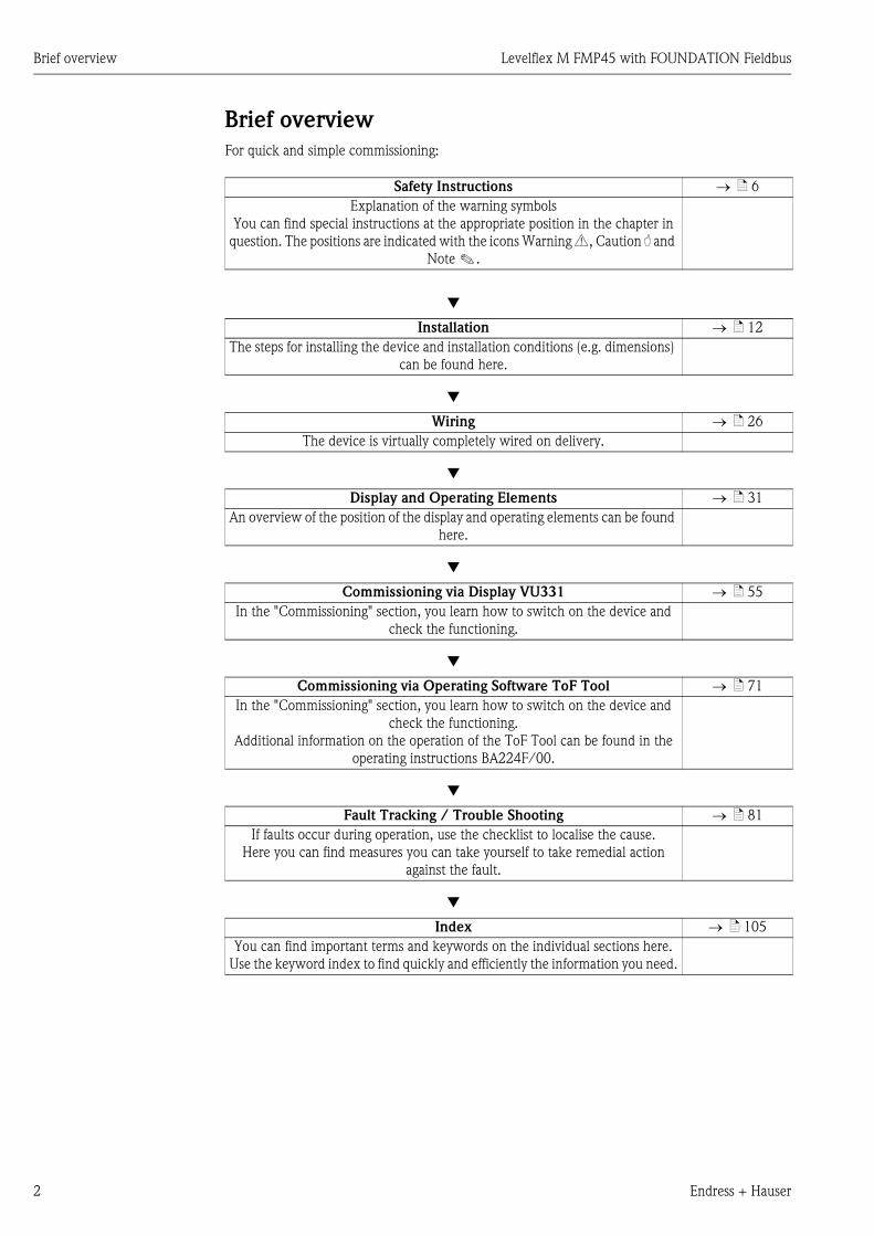
Brief overview
For quick and simple commissioning:
Safety Instructions → ä 6
Explanation of the warning symbols
You can find special instructions at the appropriate position in the chapter in
question. The positions are indicated with the icons Warning #, Caution " and
Note !.
Æ
Installation → ä 12
The steps for installing the device and installation conditions (e.g. dimensions)
can be found here.
Æ
Wiring → ä 26
The device is virtually completely wired on delivery.
Æ
Display and Operating Elements → ä 31
An overview of the position of the display and operating elements can be found
here.
Æ
Commissioning via Display VU331 → ä 55
In the "Commissioning" section, you learn how to switch on the device and
check the functioning.
Æ
Commissioning via Operating Software ToF Tool → ä 71
In the "Commissioning" section, you learn how to switch on the device and
check the functioning.
Additional information on the operation of the ToF Tool can be found in the
operating instructions BA224F/00.
Æ
Fault Tracking / Trouble Shooting → ä 81
If faults occur during operation, use the checklist to localise the cause.
Here you can find measures you can take yourself to take remedial action
against the fault.
Æ
Index → ä 105
You can find important terms and keywords on the individual sections here.
Use the keyword index to find quickly and efficiently the information you need.
Levelflex M FMP45 with FOUNDATION Fieldbus Brief overview
Endress + Hauser 3
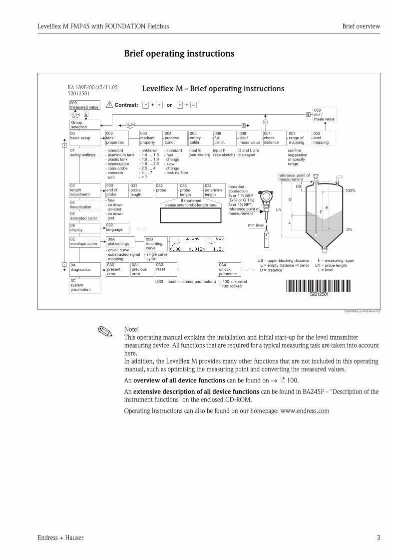
Brief operating instructions
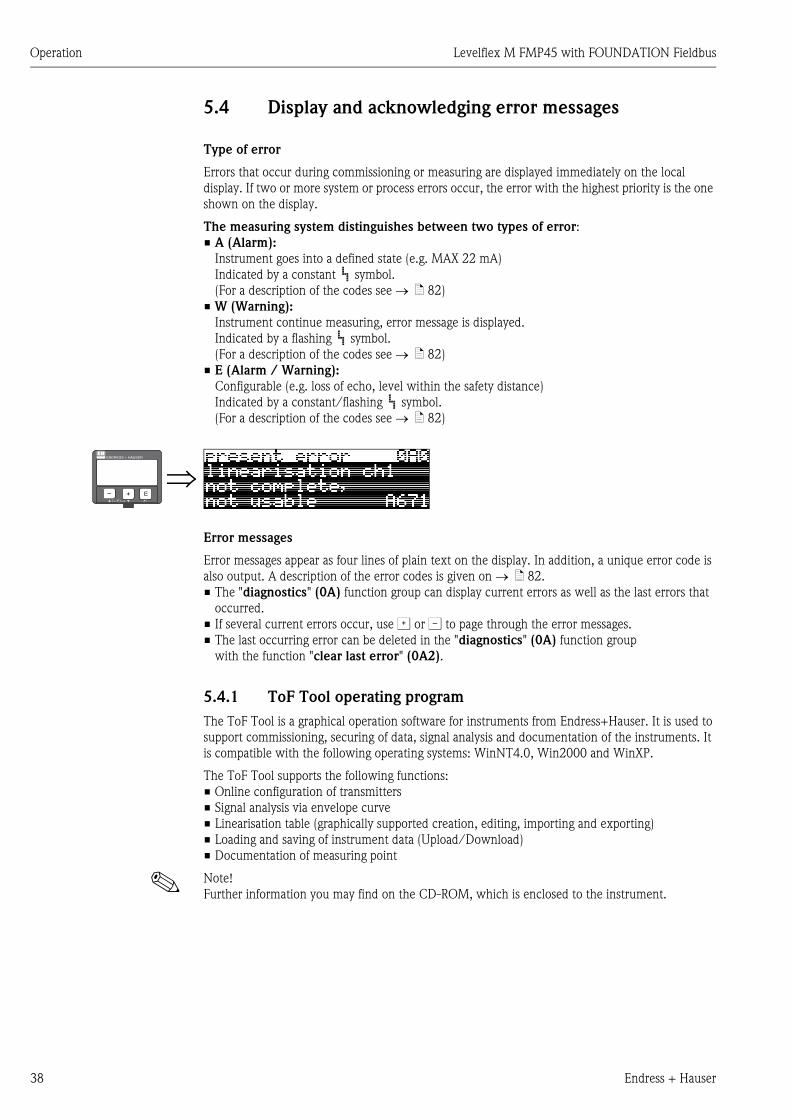
L00-FMP40xxx-19-00-00-en-012
! Note!
This operating manual explains the installation and initial start-up for the level transmitter
measuring device. All functions that are required for a typical measuring task are taken into account
here.
In addition, the Levelflex M provides many other functions that are not included in this operating
manual, such as optimising the measuring point and converting the measured values.
An overview of all device functions can be found on → ä 100.
An extensive description of all device functions can be found in BA245F – "Description of the
instrument functions" on the enclosed CD-ROM.
Operating Instructions can also be found on our homepage: www.endress.com
E+-
+
E+-E
E
-
… …
… …
KA 189F/00/a2/11.0552012501
52012501
100%
0%
FE
UB
LN
D
L
Levelflex M - Brief operating instructions
input E(see sketch)
input F(see sketch) displayed
D and L are confirm
or specifyrange
suggestion
000measured value
Groupselection
00basic setup
01safety settings
09display
04linearisation
05extended calibr.
0Csystemparameters
092language
0Adiagnostics
0A0presenterror
002tankproperties
004processcond.
005emptycalibr.
006fullcalibr.
008dist./meas value
051checkdistance
003mediumproperty
052range ofmapping
053startmapping
008dist./meas value
- envel. curve- substracted signal- mapping
- single curve- cyclic
= 100: unlocked¹ 100: locked
09Aplot settings
09Brecordingcurve
0A1previouserror
0A4unlockparameter
(333 = reset customer parameters)
0A3reset
min. level
threadedconnection
1 ½(G 1
:reference point ofmeasurement
¾ or BSP¾ or G ½)
¾ or 1½ NPT
03lengthadjustment
030end ofprobe
031probelength
032probe
033probelength
034determinelength
- unknown- 1.4 … 1.6- 1.6 … 1.9- 1.9 … 2.5
- 4 … 7- 2.5 … 4
- > 7
0Eenvelope curve
Contrast: + or +
- standard- aluminium tank- plastic tank- bypass/pipe- coax-probe- concretewall
- standard- fastchange
- test: no filter
- slowchange
- free- tie downisolated
- tie downgnd.
If shortenedplease enter probe length here.
reference point ofmeasurement
F = measuring span
E = empty distance (= zero)
UB = upper blocking distance
LN = probe lengthL = levelD = distance

Brief overview Levelflex M FMP45 with FOUNDATION Fieldbus
4 Endress + Hauser
Levelflex M FMP45 with FOUNDATION Fieldbus Table of contents
Endress + Hauser 5
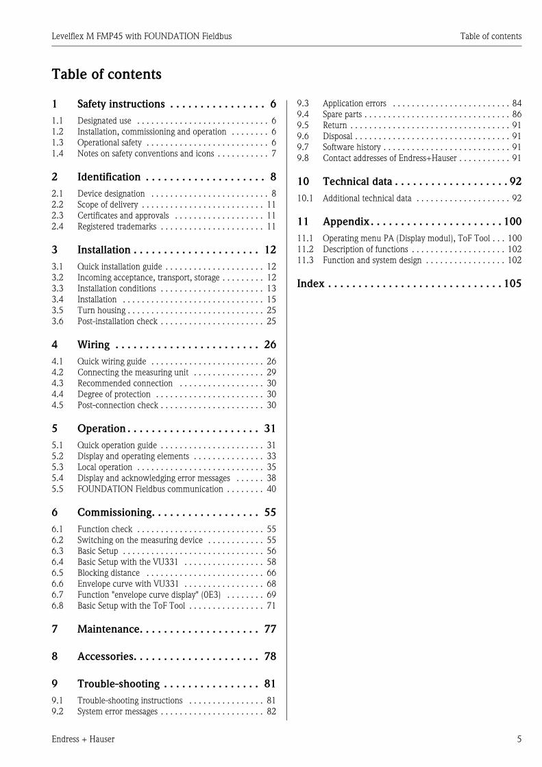
Table of contents
1 Safety instructions . . . . . . . . . . . . . . . . 6
1.1 Designated use . . . . . . . . . . . . . . . . . . . . . . . . . . . . 6
1.2 Installation, commissioning and operation . . . . . . . . 6
1.3 Operational safety . . . . . . . . . . . . . . . . . . . . . . . . . . 6
1.4 Notes on safety conventions and icons . . . . . . . . . . . 7
2 Identification . . . . . . . . . . . . . . . . . . . . 8
2.1 Device designation . . . . . . . . . . . . . . . . . . . . . . . . . 8
2.2 Scope of delivery . . . . . . . . . . . . . . . . . . . . . . . . . . 11
2.3 Certificates and approvals . . . . . . . . . . . . . . . . . . . 11
2.4 Registered trademarks . . . . . . . . . . . . . . . . . . . . . . 11
3 Installation . . . . . . . . . . . . . . . . . . . . . 12
3.1 Quick installation guide . . . . . . . . . . . . . . . . . . . . . 12
3.2 Incoming acceptance, transport, storage . . . . . . . . . 12
3.3 Installation conditions . . . . . . . . . . . . . . . . . . . . . . 13
3.4 Installation . . . . . . . . . . . . . . . . . . . . . . . . . . . . . . 15
3.5 Turn housing . . . . . . . . . . . . . . . . . . . . . . . . . . . . . 25
3.6 Post-installation check . . . . . . . . . . . . . . . . . . . . . . 25
4 Wiring . . . . . . . . . . . . . . . . . . . . . . . . 26
4.1 Quick wiring guide . . . . . . . . . . . . . . . . . . . . . . . . 26
4.2 Connecting the measuring unit . . . . . . . . . . . . . . . 29
4.3 Recommended connection . . . . . . . . . . . . . . . . . . 30
4.4 Degree of protection . . . . . . . . . . . . . . . . . . . . . . . 30
4.5 Post-connection check . . . . . . . . . . . . . . . . . . . . . . 30
5 Operation . . . . . . . . . . . . . . . . . . . . . . 31
5.1 Quick operation guide . . . . . . . . . . . . . . . . . . . . . . 31
5.2 Display and operating elements . . . . . . . . . . . . . . . 33
5.3 Local operation . . . . . . . . . . . . . . . . . . . . . . . . . . . 35
5.4 Display and acknowledging error messages . . . . . . 38
5.5 FOUNDATION Fieldbus communication . . . . . . . . 40
6 Commissioning. . . . . . . . . . . . . . . . . . 55
6.1 Function check . . . . . . . . . . . . . . . . . . . . . . . . . . . 55
6.2 Switching on the measuring device . . . . . . . . . . . . 55
6.3 Basic Setup . . . . . . . . . . . . . . . . . . . . . . . . . . . . . . 56
6.4 Basic Setup with the VU331 . . . . . . . . . . . . . . . . . 58
6.5 Blocking distance . . . . . . . . . . . . . . . . . . . . . . . . . 66
6.6 Envelope curve with VU331 . . . . . . . . . . . . . . . . . 68
6.7 Function "envelope curve display" (0E3) . . . . . . . . 69
6.8 Basic Setup with the ToF Tool . . . . . . . . . . . . . . . . 71
7 Maintenance. . . . . . . . . . . . . . . . . . . . 77
8 Accessories. . . . . . . . . . . . . . . . . . . . . 78
9 Trouble-shooting . . . . . . . . . . . . . . . . 81
9.1 Trouble-shooting instructions . . . . . . . . . . . . . . . . 81
9.2 System error messages . . . . . . . . . . . . . . . . . . . . . . 82
9.3 Application errors . . . . . . . . . . . . . . . . . . . . . . . . . 84
9.4 Spare parts . . . . . . . . . . . . . . . . . . . . . . . . . . . . . . . 86
9.5 Return . . . . . . . . . . . . . . . . . . . . . . . . . . . . . . . . . . 91
9.6 Disposal . . . . . . . . . . . . . . . . . . . . . . . . . . . . . . . . . 91
9.7 Software history . . . . . . . . . . . . . . . . . . . . . . . . . . . 91
9.8 Contact addresses of Endress+Hauser . . . . . . . . . . . 91
10 Technical data . . . . . . . . . . . . . . . . . . . 92
10.1 Additional technical data . . . . . . . . . . . . . . . . . . . . 92
11 Appendix. . . . . . . . . . . . . . . . . . . . . . 100
11.1 Operating menu PA (Display modul), ToF Tool . . . 100
11.2 Description of functions . . . . . . . . . . . . . . . . . . . . 102
11.3 Function and system design . . . . . . . . . . . . . . . . . 102
Index . . . . . . . . . . . . . . . . . . . . . . . . . . . . . 105
Safety instructions Levelflex M FMP45 with FOUNDATION Fieldbus
6 Endress + Hauser
1 Safety instructions
1.1 Designated use
The Levelflex M FMP45 is a compact level transmitter for the continuous measurement of solids
and liquids, measuring prinziple: Guided Level Radar / TDR: Time Domain Reflectometry.
1.2 Installation, commissioning and operation
The Levelflex M has been designed to operate safely in accordance with current technical, safety
and EU standards. If installed incorrectly or used for applications for which it is not intended,
however, it is possible that application-related dangers may arise, e.g. product overflow due to
incorrect installation or calibration. For this reason, the instrument must be installed, connected,
operated and maintained according to the instructions in this manual: personnel must be authorised
and suitably qualified. The manual must have been read and understood, and the instructions
followed. Modifications and repairs to the device are permissible only when they are expressly
approved in the manual.
1.3 Operational safety
Hazardous areas
Measuring systems for use in hazardous environments are accompanied by separate "Ex
documentation", which is an integral part of this Operating Manual. Strict compliance with the
installation instructions and ratings as stated in this supplementary documentation is mandatory.
• Ensure that all personnel are suitably qualified.
• Observe the specifications in the certificate as well as national and local regulations.
Levelflex M FMP45 with FOUNDATION Fieldbus Safety instructions
Endress + Hauser 7
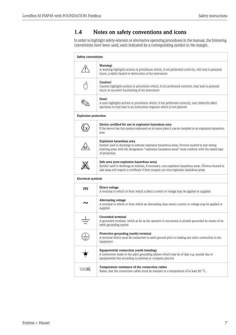
1.4 Notes on safety conventions and icons
In order to highlight safety-relevant or alternative operating procedures in the manual, the following
conventions have been used, each indicated by a corresponding symbol in the margin.
Safety conventions
#Warning!
A warning highlights actions or procedures which, if not performed correctly, will lead to personal
injury, a safety hazard or destruction of the instrument
"Caution!
Caution highlights actions or procedures which, if not performed correctly, may lead to personal
injury or incorrect functioning of the instrument
!Note!
A note highlights actions or procedures which, if not performed correctly, may indirectly affect
operation or may lead to an instrument response which is not planned
Explosion protection
0Device certified for use in explosion hazardous area
If the device has this symbol embossed on its name plate it can be installed in an explosion hazardous
area
-Explosion hazardous area
Symbol used in drawings to indicate explosion hazardous areas. Devices located in and wiring
entering areas with the designation “explosion hazardous areas” must conform with the stated type
of protection.
.Safe area (non-explosion hazardous area)
Symbol used in drawings to indicate, if necessary, non-explosion hazardous areas. Devices located in
safe areas still require a certificate if their outputs run into explosion hazardous areas
Electrical symbols
% Direct voltage
A terminal to which or from which a direct current or voltage may be applied or supplied
&Alternating voltage
A terminal to which or from which an alternating (sine-wave) current or voltage may be applied or
supplied
)Grounded terminal
A grounded terminal, which as far as the operator is concerned, is already grounded by means of an
earth grounding system
*Protective grounding (earth) terminal
A terminal which must be connected to earth ground prior to making any other connection to the
equipment
+Equipotential connection (earth bonding)
A connection made to the plant grounding system which may be of type e.g. neutral star or
equipotential line according to national or company practice
Temperature resistance of the connection cables
States, that the connection cables must be resistant to a temperature of at least 85 °C.t >85°C
Identification Levelflex M FMP45 with FOUNDATION Fieldbus
8 Endress + Hauser
2 Identification
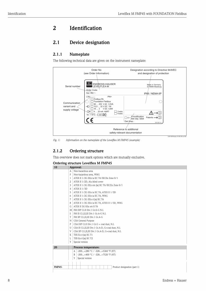
2.1 Device designation
2.1.1 Nameplate
The following technical data are given on the instrument nameplate:
L00-FMP4xxxx-18-00-00-en-001
Fig. 1: Information on the nameplate of the Levelflex M FMP45 (example)
2.1.2 Ordering structure
This overview does not mark options which are mutually exclusive.
Ordering structure Levelflex M FMP45
Made in GermanyD-79689 Maulburg
Dat./Insp.:
Order Code:
IP68 / NEMA 6PSer.-No.:
4-wire
ENDRESS+HAUSER
t >85°CTA > 70°C :
D01301-A
if modificationsee sep. labelX = Patents
LEVELFLEX-M
90 … 253 V AC 3,5VA10,5 … 32 V DC 1W16 … 3 V DC 0,8W
Profibus PAFoundation Fieldbus
LN= PN=
4 … 20 mA HART 2-wire
Order No(see Order Information)
Communicationvariant andsupply voltage
Serial number
Reference to additionalsafety-relevant documentation
Designation according to Directive 94/9/ECand designation of protection
10 Approval:
A Non-hazardous area
F Non-hazardous area, WHG
1 ATEX II 1/2G EEx ia IIC T6/IECEx Zone 0/1
2 ATEX II 1/2D, Alu blind cover
3 ATEX II 1/2G EEx em [ia] IIC T6/IECEx Zone 0/1
4 ATEX II 1/3D
5 ATEX II 1/2G EEx ia IIC T6, ATEX II 1/3D
6 ATEX II 1/2G EEx ia IIC T6, WHG
7 ATEX II 1/2G EEx d [ia] IIC T6
8 ATEX II 1/2G EEx ia IIC T6, ATEX II 1/3D, WHG
G ATEX II 3G EEx nA II T6
M FM DIP Cl.II Div.1 Gr.E-G N.I.
S FM IS Cl.I,II,III Div.1 Gr.A-G N.I.
T FM XP Cl.I,II,III Div.1 Gr.A-G
N CSA General Purpose
P CSA DIP Cl.II Div.1 Gr.G + coal dust, N.I.
U CSA IS Cl.I,II,III Div.1 Gr.A-D, G+coal dust, N.I.
V CSA XP Cl.I,II,III Div.1 Gr.A-D, G+coal dust, N.I.
K TIIS Ex d [ia] IIC T1
L TIIS Ex d [ia] IIC T2
Y Special version
20 Process temperature:
A -200...+280 °C / -328...+5360 °F (XT)
B -200...+400 °C / -328...+7520 °F (HT)
Y Special version
FMP45- Product designation (part 1)

Levelflex M FMP45 with FOUNDATION Fieldbus Identification
Endress + Hauser 9
Ordering structure Levelflex M FMP45 (continued)30 Probe:
A .....mm, rope 4mm, 316
C .....inch, rope 1/16", 316
K .....mm, rod 16 mm, 316L
L .....mm, coax , 316L
M .....inch, rod 16 mm, 316L
N .....inch, coax, 316L
Y Special version
40 Process Connection:
AFJ 2" 150lbs RF, 316/316L flange ASME B16.5
AGJ 3" 150lbs RF, 316/316L flange ASME B16.5
AHJ 4" 150lbs RF, 316/316L flange ASME B16.5
ARJ 2" 300/600lbs RF, 316/316L flange ASME B16.5
ASJ 3" 300/600lbs RF, 316/316L flange ASME B16.5
ATJ 4" 300lbs RF, 316/316L flange ASME B16.5
A1J 2" 1500lbs RF, 316/316L flange ASME B16.5
A2J 3" 1500lbs RF, 316/316L flange ASME B16.5
A3J 4" 600lbs RF, 316/316L flange ASME B16.5
A4J 4" 900lbs RF, 316/316L flange ASME B16.5
A5J 4" 1500lbs RF, 316/316L flange ASME B16.5
CHJ DN100 PN10/16 B1, 316L flange EN1092-1 (DIN2527 C)
CRJ DN50 PN10-40 B1, 316L flange EN1092-1 (DIN2527 C)
CSJ DN80 PN10-40 B1, 316L flange EN1092-1 (DIN2527 C)
CTJ DN100 PN25/40 B1, 316L flange EN1092-1 (DIN2527 C)
C1J DN50 PN63 B2, 316L flange EN1092-1 (DIN2527 E)
C2J DN50 PN100 B2, 316L flange EN1092-1 (DIN2527 E)
C3J DN80 PN63 B2, 316L flange EN1092-1 (DIN2527 E)
C4J DN80 PN100 B2, 316L flange EN1092-1 (DIN2527 E)
C5J DN100 PN63 B2, 316L flange EN1092-1 (DIN2527 E)
C6J DN100 PN100 B2, 316L flange EN1092-1 (DIN2527 E)
KFJ 10K 50 RF, 316L flange JIS B2220
KGJ 10K 80 RF, 316L flange JIS B2220
KHJ 10K 100 RF, 316L flange JIS B2220
K3J 63K 50 RF, 316L flange JIS B2220
K4J 63K 80 RF, 316L flange JIS B2220
K5J 63K 100 RF, 316L flange JIS B2220
40 Prozessanschluss:
GGJ Thread ISO228 G1-1/2, 200bar, 316L
GJJ Thread ISO228 G1-1/2, 400bar, 316L
RGJ Thread ANSI NPT1-1/2, 200bar, 316L
RJJ Thread ANSI NPT1-1/2, 400bar, 316L, High pressure test
YY9 Special version
FMP45- Product designation (part 2)

Identification Levelflex M FMP45 with FOUNDATION Fieldbus
10 Endress + Hauser
Ordering structure Levelflex M FMP45 (continued)50 Power Supply; Output:
B 2-wire; 4-20mA HART
D 2-wire; PROFIBUS -PA
F 2-wire; FOUNDATION Fieldbus
G 4-wire 90-250VAC; 4-20mA HART
H 4-wire 10.5-32VDC; 4-20mA HART
Y Special version
60 Operation:
1 W/o display, via communication
2 4-line display VU331, Envelope curve display on site
3 Prepared for FHX40, Remote display (accessory)
9 Special version
70 Type of Probe:
1 Compact, basic version
3 Remote, cable 3m, top entry
4 Remote, cable 3m, side entry
9 Special version
80 Housing:
A F12 Alu, coated IP68 NEMA6P
B F23 316L IP68 NEMA6P
C T12 Alu, coated IP68 NEMA6P, Separate conn. compartment,
D T12 Alu, coated IP68 NEMA6P + OVP, Separate conn. compartment,
OVP = overvoltage protection
Y Special version
90 Cable Entry:
2 Gland M20 (EEx d > thread M20)
3 Thread G1/2
4 Thread NPT1/2
5 Plug M12
6 Plug 7/8"
9 Special version
100 Additional Option:
A Basic version
B EN10204-3.1 material, wetted parts,
(316L wetted parts for rod/coax) inspection certificate
C EN10204-3.1 material, wetted parts,
(316L pressurized for rope version) inspection certificate
N EN10204-3.1 material, NACE MR0175,
(316L wetted parts) inspection certificate
Y Special version
FMP45- Complete product designation
⇓
Please enter probe length in mm or inch / 0.1 inch
mm
inch / 0.1 inch
probe length LN → ä 14
Levelflex M FMP45 with FOUNDATION Fieldbus Identification
Endress + Hauser 11
2.2 Scope of delivery
" Caution!
It is essential to follow the instructions concerning the unpacking, transport and storage of
measuring instruments given in the chapter "Incoming acceptance, transport, storage" on → ä 12!
The scope of delivery consists of:
• Assembled instrument
• 2 ToF Tool - FieldTool® Package CD-ROMs
– CD 1: ToF Tool - FieldTool® Program
Program including Device Descriptions (device drivers) for all Endress+Hauser devices wich are
operable using ToF Tool
– CD 2: ToF Tool - FieldTool® Documentation
Documentation for all Endress+Hauser devices wich are operable using ToF Tool)
• Accessories (→ Chap. 8).
Accompanying documentation:
• Short manual (basic setup/troubleshooting): housed in the instrument
• Operating manual (this manual)
• Approval documentation: if this is not included in the operating manual.
! Note!
The operating manual BA245F - "Description of Instrument functions" you can be found on the
enclosed CD-ROM.
2.3 Certificates and approvals
CE mark, declaration of conformity
The device is designed to meet state-of-the-art safety requirements, has been tested and left the
factory in a condition in which it is safe to operate. The device complies with the applicable
standards and regulations as listed in the EC declaration of conformity and thus complies with the
statutory requirements of the EG directives. Endress+Hauser confirms the successful testing of the
device by affixing to it the CE mark.
2.4 Registered trademarks
KALREZ®, VITON®, TEFLON®
Registered trademark of the company, E.I. Du Pont de Nemours & Co., Wilmington, USA
TRI-CLAMP®
Registered trademark of the company, Ladish & Co., Inc., Kenosha, USA
HART®
Registered trademark of HART Communication Foundation, Austin, USA
ToF®
Registered trademark of the company Endress+Hauser GmbH+Co. KG, Maulburg, Germany
PulseMaster®
Registered trademark of the company Endress+Hauser GmbH+Co. KG, Maulburg, Germany
Foundation™ Fieldbus
Registered trademark of Fieldbus Foundation Austin, Texas, USA

Installation Levelflex M FMP45 with FOUNDATION Fieldbus
12 Endress + Hauser
3 Installation
3.1 Quick installation guide
L00-FMP45xxx-17-00-00-en-003
3.2 Incoming acceptance, transport, storage
3.2.1 Incoming acceptance
Check the packing and contents for any signs of damage.
Check the shipment, make sure nothing is missing and that the scope of supply matches your order.
3.2.2 Transport
" Caution!
Follow the safety instructions and transport conditions for instruments of more than
18 kg.
Do not lift the measuring instrument by its probe rod in order to transport it.
3.2.3 Storage
Pack the measuring instrument so that is protected against impacts for storage and transport. The
original packing material provides the optimum protection for this.
The permissible storage temperature is -40 °C…+80 °C.
3
1
2
60
1 "½ F12 housing
Turn housingThe housing can be turned 350°in order to simplify access to the
display and the terminal compartment
AF 60
max. torquesee table
Caution!Use only thethreaded boss ???
F12 or T12 housing
torqueProcess temperature
max. 280 °C 450 Nm
max. 400 °C 400 Nm
Levelflex M FMP45 with FOUNDATION Fieldbus Installation
Endress + Hauser 13
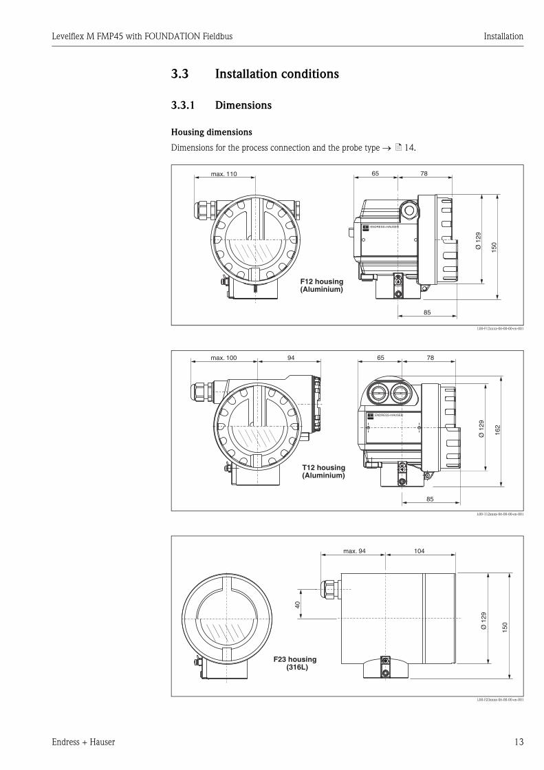
3.3 Installation conditions
3.3.1 Dimensions
Housing dimensions
Dimensions for the process connection and the probe type → ä 14.
L00-F12xxxx-06-00-00-en-001
L00-T12xxxx-06-00-00-en-001
L00-F23xxxx-06-00-00-en-001
ENDRESS+HAUSER
65 78max. 110
85
150
Ø 1
29
(Aluminium)F12 housing
ENDRESS+HAUSER
78
85
65
162
max. 100 94
Ø 1
29(Aluminium)T12 housing
max. 94 104
Ø 1
29
150
40
(316L)F23 housing
Installation Levelflex M FMP45 with FOUNDATION Fieldbus
14 Endress + Hauser
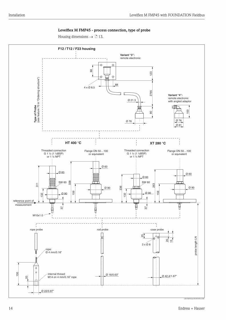
Levelflex M FMP45 - process connection, type of probe
Housing dimensions → ä 13.
L00-FMP45xxx-06-00-00-en-001
88
88
123
2765
80
Ø 76
4 x Ø 8,5
150
HT 400 °C XT 280 °C
3 x Ø 8
20 15
25
100
Ø 76
Ø 81
236 26
3
20
Threaded connectionG 1 ½ (1 ½BSP)
or 1 ½ NPT
Threaded connectionG 1 ½ (1 ½BSP)
or 1 ½ NPT
Flange DN 50…100or equivalent
Flange DN 50…100or equivalent
reference point of
measurement
rope:Ø 4 mm/0.16”
rope probe rod probe coax probe
Ø 16/0.63” Ø 42,4/1.67”
Ø 22/0.87”
prob
e le
ngth
LN
F12 / T12 / F23 housing
SW 60 SW 60
159
159
338
3737
Ø 90Ø 90
Ø 90 Ø 90
Ø 60
Ø 60
Ø 60
Ø 60
132
311
132
M10x1.0
Ø 21.3
Typ
e o
f P
rob
e(s
eefe
atur
e 70
in“O
rder
ing
stru
ctur
e”)
Variant “3”:remote electronic
Variant “4”:remote electronicwith angled adaptor
internal thread:M14 on 4 mm/0.16” rope
Levelflex M FMP45 with FOUNDATION Fieldbus Installation
Endress + Hauser 15
3.4 Installation
3.4.1 Mounting kit
In addition to the tool needed for flange mounting, you will require the following tool:
• For the mounting of threaded connection: 60 mm Open-end spanner for 1½", 50 mm Open-end
spanner for ¾".
• 4 mm Allen wrench for turning the housing.
3.4.2 Shortening probes
Rod probe
The shortening is necessary if the distance to the container floor or outlet cone is less than 50 mm.
The rods of a rod probe are shortened by sawing or separating at the bottom end.
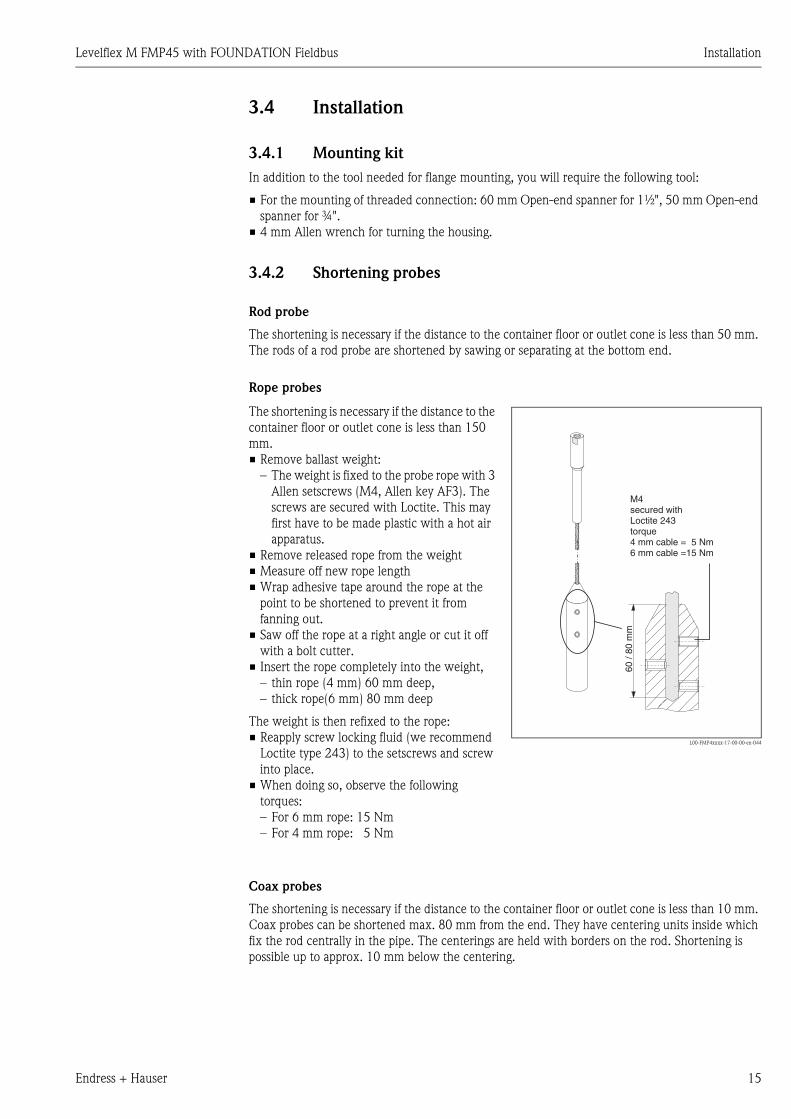
Rope probes
Coax probes
The shortening is necessary if the distance to the container floor or outlet cone is less than 10 mm.
Coax probes can be shortened max. 80 mm from the end. They have centering units inside which
fix the rod centrally in the pipe. The centerings are held with borders on the rod. Shortening is
possible up to approx. 10 mm below the centering.
The shortening is necessary if the distance to the
container floor or outlet cone is less than 150
mm.
• Remove ballast weight:
– The weight is fixed to the probe rope with 3
Allen setscrews (M4, Allen key AF3). The
screws are secured with Loctite. This may
first have to be made plastic with a hot air
apparatus.
• Remove released rope from the weight
• Measure off new rope length
• Wrap adhesive tape around the rope at the
point to be shortened to prevent it from
fanning out.
• Saw off the rope at a right angle or cut it off
with a bolt cutter.
• Insert the rope completely into the weight,
– thin rope (4 mm) 60 mm deep,
– thick rope(6 mm) 80 mm deep
The weight is then refixed to the rope:
• Reapply screw locking fluid (we recommend
Loctite type 243) to the setscrews and screw
into place.
• When doing so, observe the following
torques:
– For 6 mm rope: 15 Nm
– For 4 mm rope: 5 Nm
L00-FMP4xxxx-17-00-00-en-044
60 /
80 m
m
M4secured withLoctite 243torque4 mm cable = 5 Nm6 mm cable =15 Nm
Installation Levelflex M FMP45 with FOUNDATION Fieldbus
16 Endress + Hauser
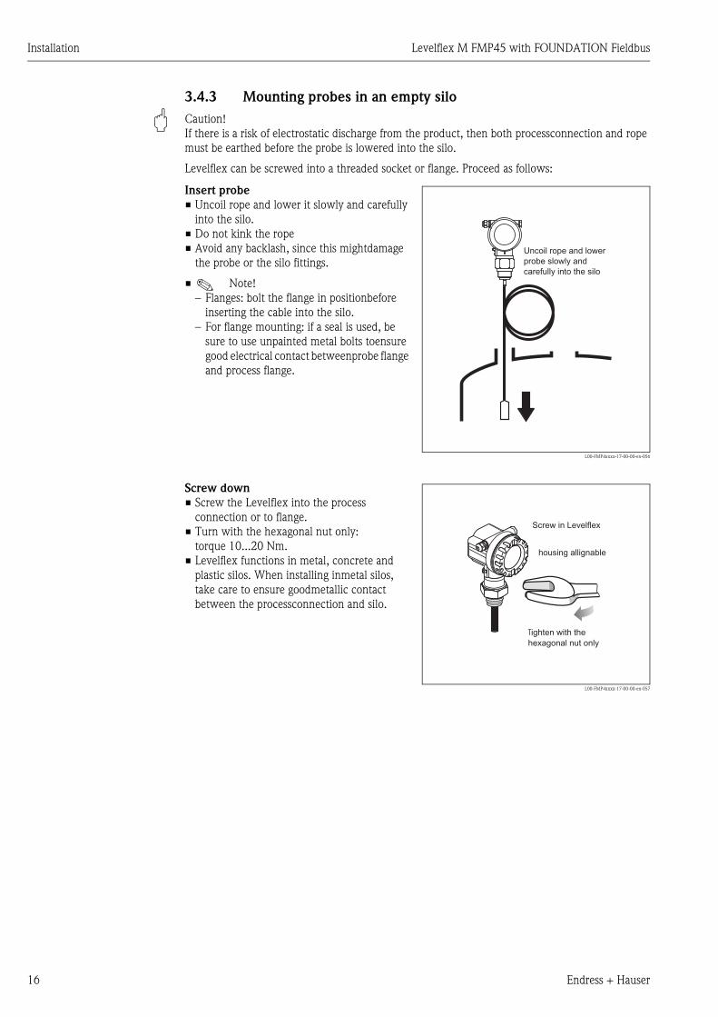
3.4.3 Mounting probes in an empty silo
" Caution!
If there is a risk of electrostatic discharge from the product, then both processconnection and rope
must be earthed before the probe is lowered into the silo.
Levelflex can be screwed into a threaded socket or flange. Proceed as follows:
Insert probe
• Uncoil rope and lower it slowly and carefully
into the silo.
• Do not kink the rope
• Avoid any backlash, since this mightdamage
the probe or the silo fittings.
• ! Note!
– Flanges: bolt the flange in positionbefore
inserting the cable into the silo.
– For flange mounting: if a seal is used, be
sure to use unpainted metal bolts toensure
good electrical contact betweenprobe flange
and process flange.
L00-FMP4xxxx-17-00-00-en-056
Uncoil rope and lower
probe slowly and
carefully into the silo
Screw down
• Screw the Levelflex into the process
connection or to flange.
• Turn with the hexagonal nut only:
torque 10...20 Nm.
• Levelflex functions in metal, concrete and
plastic silos. When installing inmetal silos,
take care to ensure goodmetallic contact
between the processconnection and silo.
L00-FMP4xxxx-17-00-00-en-057
Screw in Levelflex
housing allignable
Tighten with the
hexagonal nut only
Levelflex M FMP45 with FOUNDATION Fieldbus Installation
Endress + Hauser 17
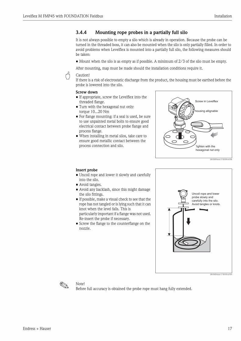
3.4.4 Mounting rope probes in a partially full silo
It is not always possible to empty a silo which is already in operation. Because the probe can be
turned in the threaded boss, it can also be mounted when the silo is only partially filled. In order to
avoid problems when Levelflex is mounted into a partially full silo, the following measures should
be taken:
• Mount when the silo is as empty as if possible. A minimum of 2/3 of the silo must be empty.
After mounting, map must be made should the installation conditions require it.
" Caution!
If there is a risk of electrostatic discharge from the product, the housing must be earthed before the
probe is lowered into the silo.
! Note!
Before full accuracy is obtained the probe rope must hang fully extended.
Screw down
• If appropriate, screw the Levelflex into the
threaded flange.
• Turn with the hexagonal nut only:
torque 10...20 Nm
• For flange mounting: if a seal is used, be sure
to use unpainted metal bolts to ensure good
electrical contact between probe flange and
process flange.
• When installing in metal silos, take care to
ensure good metallic contact between the
process connection and silo.
L00-FMP4xxxx-17-00-00-en-058
Screw in Levelflex
housing allignable
Tighten with the
hexagonal nut only
Insert probe
• Uncoil rope and lower it slowly and carefully
into the silo.
• Avoid tangles.
• Avoid any backlash, since this might damage
the silo fittings.
• If possible, make a visual check to see that the
rope has not tangled or is lying such that it can
knot when the level falls. This is
particularly important if a flange was not used.
Re-insert the probe if necessary.
• Screw the flange to the counterflange on the
nozzle.
L00-FMP4xxxx-17-00-00-en-059
Uncoil rope and lower
probe slowly and
carefully into the silo.
Avoid tangles or knots.

Installation Levelflex M FMP45 with FOUNDATION Fieldbus
18 Endress + Hauser
3.4.5 General instructions
Normally use rod probes. Rope probes are used in liquids for measuring ranges > 4m and with
restricted ceiling clearance which does not allow the installation of rigid probes.
Coax probes are not influenced by the installation conditions. They may also be operated
• in the filling curtain
• in arbitrary proximity to internal fittings
• at viscositys up to 500 cSt.
! Note!
Seal for devices with G 1½" thread
The thread and the type of seal comply to DIN 3852 part 1, screwed end type A. Gaskets according
to DIN 7603 with a dimesnion of 48x55mm can be used for it. Please use a gasket according to this
standard in the form A, C or D and of a material that is resistant to your application.
Mounting location
• Do not mount rod or rope probes in the filling
curtain (2).
• Mount rod and rope probes away from the
wall (B) at such a distance that, in the event of
build-up on the wall, there is still a minimum
distance of 100 mm between the probe and
the build-up.
• Mount rod and rope probes as far away as
possible from installed fittings. "Mapping "
must be carried out during commissioning in
the event of distances < 300 mm.
• Minimum distance of probe end to the
container floor (C):
– Rope probe: 150 mm
– Rod probe: 100 mm
– Coax probe: 10 mm
• When installing outdoors, it is recommended
that you use a protective cover (1) see
Accessories on → ä 78.
L00-FMP4xxxx-17-00-00-xx-007
B
C
1 2
Levelflex M FMP45 with FOUNDATION Fieldbus Installation
Endress + Hauser 19
Minimum distance B of rod and rope probes to the container wall:
The wall clearance can be chosen as desired as long as the probe does not touch the tank wall.
! Note!
• There should no bridges to the wall created by soiling or highly viscous media.
Welding the probe into the vessel
" Caution!
Before welding the probe into the vessel, it must be grounded by a low-resistive connection. If this
is not possible, the electronics as well as the HF module must be disconnected. Otherwise the
electronics may be damaged.
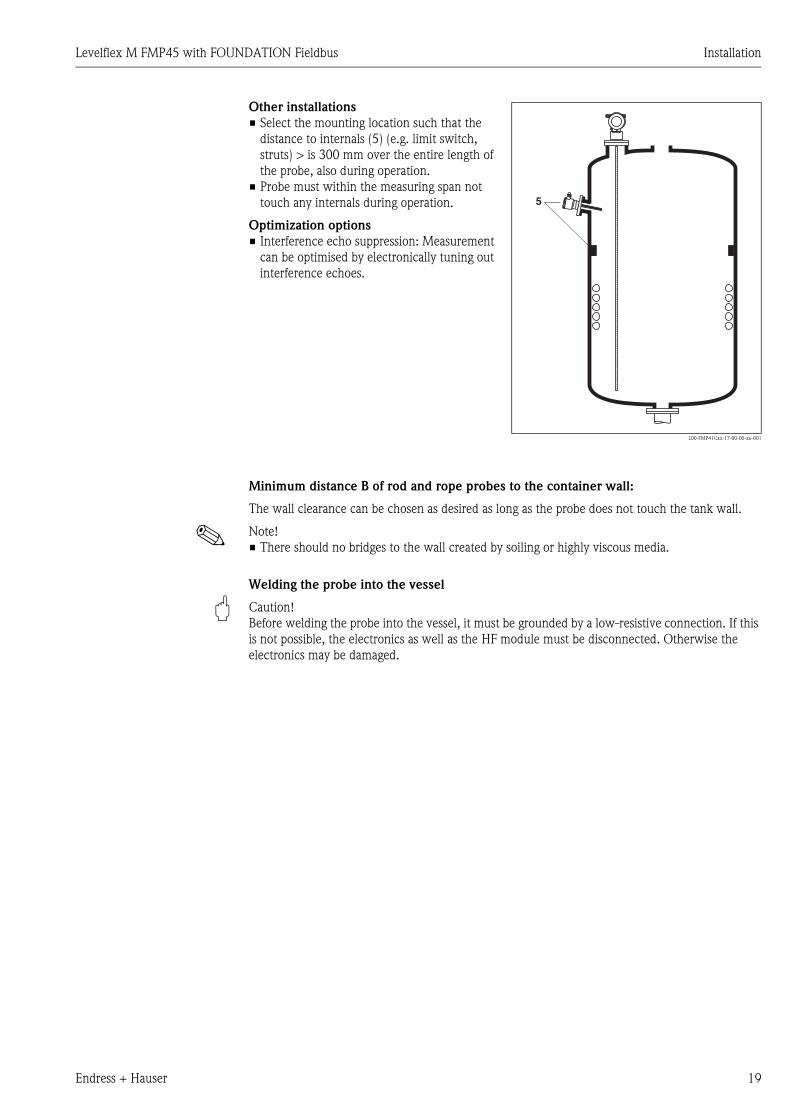
Other installations
• Select the mounting location such that the
distance to internals (5) (e.g. limit switch,
struts) > is 300 mm over the entire length of
the probe, also during operation.
• Probe must within the measuring span not
touch any internals during operation.
Optimization options
• Interference echo suppression: Measurement
can be optimised by electronically tuning out
interference echoes.
L00-FMP41Cxx-17-00-00-xx-001
5
Installation Levelflex M FMP45 with FOUNDATION Fieldbus
20 Endress + Hauser
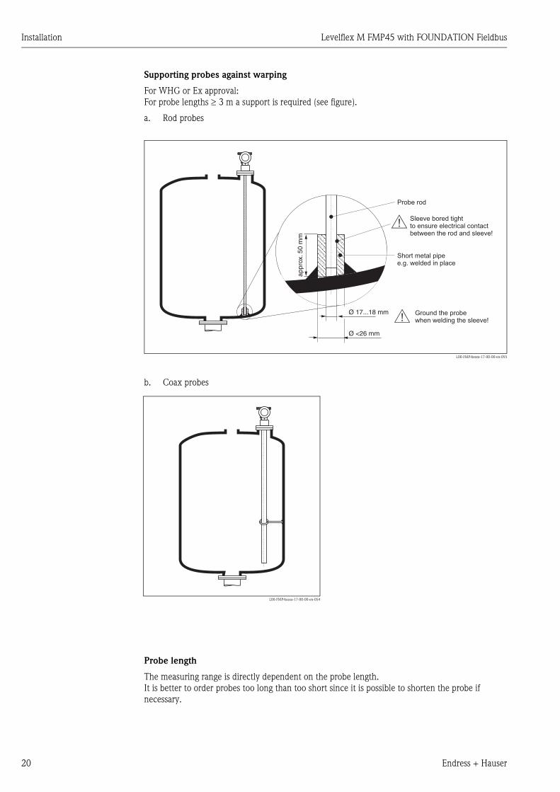
Supporting probes against warping
For WHG or Ex approval:
For probe lengths ≥ 3 m a support is required (see figure).
a. Rod probes
L00-FMP4xxxx-17-00-00-en-055
b. Coax probes
Probe length
The measuring range is directly dependent on the probe length.
It is better to order probes too long than too short since it is possible to shorten the probe if
necessary.
Ø <26 mm
#
#Ø 17...18 mm
Probe rod
Short metal pipee.g. welded in place
appr
ox. 5
0 m
m
Sleeve bored tightto ensure electrical contactbetween the rod and sleeve!
Ground the probewhen welding the sleeve!
L00-FMP4xxxx-17-00-00-en-054
Levelflex M FMP45 with FOUNDATION Fieldbus Installation
Endress + Hauser 21
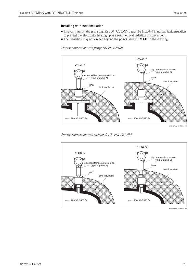
Installing with heat insulation
• If process temperatures are high (≥ 200 °C), FMP45 must be included in normal tank insulation
to prevent the electronics heating up as a result of heat radiation or convection.
• The insulation may not exceed beyond the points labelled "MAX" in the drawing.
Process connection with flange DN50...DN100
L00-FMP45xxx-17-00-00-en-001
Process connection with adapter G 1½" and 1½" NPT
L00-FMP45xxx-17-00-00-en-002
MAX
MAX
HT 400 °C
XT 280 °C
max. 400° C (752° F)max. 280° C (536° F)
tank insulation
tank insulation
high temperature version(type of probe B)
extended temperature version(type of probe A)
MAX
MAX
HT 400 °C
XT 280 °C
max. 400° C (752° F)max. 280° C (536° F)
tank insulation
tank insulation
high temperature version(type of probe B)
extended temperature version(type of probe A)

Installation Levelflex M FMP45 with FOUNDATION Fieldbus
22 Endress + Hauser
3.4.6 Special instructions
When installing in stirring tanks, observe lateral load of probes. Possibly check whether a non-
contact radar would not be better suited, above all if the stirrer generates large mechanical loads on
the probe.
" Caution!
In vacuum applications and in applications where extremely condensate fermation may occur, there
is the danger that the vessel is completely flooded. For media groups with high DC values, this may
result in a measuring value lower than the actual level. Please contact your local Endress+Hauser
representative for remedial actions.
Installation in horizontal cylindrical and
standing tanks
• Use a rod probe for measuring ranges up to 4
m. For anything over this or if there is too free
cover space use a rope probe.
• Any distance from wall, as long as occasional
contact is prevented.
• When using metal tanks, it is preferable to
mount probes (1) eccentrically.
L00-FMP4xxxx-17-00-00-yy-049
1
Installation in stilling well or bypass
• Rod and rope probes can also be installed in
pipes (stilling well, bypass).
• When installing in metal pipes up to DN 150/
6", the measuring sensitivity of the device
increases such that liquids as of DK 1.4 can be
measured.
• Welded joints that protrude up to approx. 5
mm/0.2" inwards do not influence
measurement.
L00-FMP4xxxx-17-00-00-yy-023
Levelflex M FMP45 with FOUNDATION Fieldbus Installation
Endress + Hauser 23
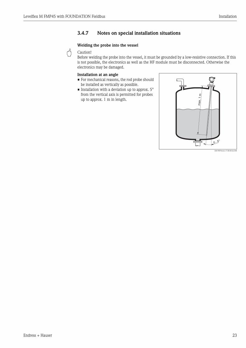
3.4.7 Notes on special installation situations
Welding the probe into the vessel
" Caution!
Before welding the probe into the vessel, it must be grounded by a low-resistive connection. If this
is not possible, the electronics as well as the HF module must be disconnected. Otherwise the
electronics may be damaged.
Installation at an angle
• For mechanical reasons, the rod probe should
be installed as vertically as possible.
• Installation with a deviation up to approx. 5°
from the vertical axis is permitted for probes
up to approx. 1 m in length.
L00-FMP4xxxx-17-00-00-de-048
0...5°
max.1
m

Installation Levelflex M FMP45 with FOUNDATION Fieldbus
24 Endress + Hauser
3.4.8 Installation for difficult to access process connections
Installation with remote electronic
• Follow installation instructions on → ä 18
• Mount housing on a wall or pipe as shown in the diagram.
L00-FMP4xxxx-17-00-00-en-015
! Note!
The protective hose cannot be disassembled at these points (1).
The ambient temperature for the connecting line (2) between the probe and the electronics must
not be greater than 105°C. For the remote electronics, temperatures up to 280 °C or 400 °C
(depending on the instrumeent version) are admissible at the process connection. The version with
remote electronics consists of the probe, a connecting cable and the housing. If they are ordered as
a complete unit they will be delivered assembled and cannot be separated.
150
ENDRESS+HAUSERLevelflex M
65 78
Ø 1
29
85
150
ENDRESS+HAUSERLevelflex M
65 78
Ø 1
29
85
52
52
150
max
.80
min
.30
96
94
94
88
88
123
2765
112
190
≥75
Ø 76
1
1
4 x Ø 8,5
1
1
2
pipe
wall
Note min.bend radius!
Ø 21.3
Levelflex M FMP45 with FOUNDATION Fieldbus Installation
Endress + Hauser 25
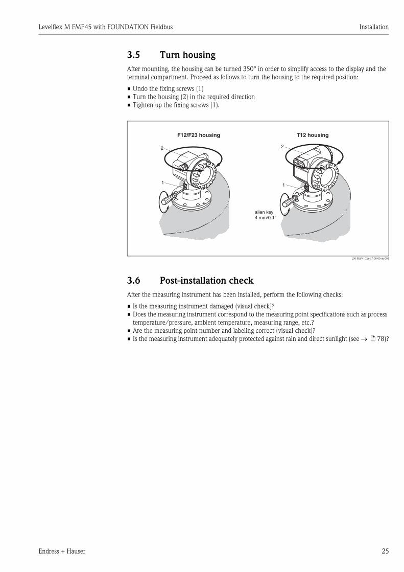
3.5 Turn housing
After mounting, the housing can be turned 350° in order to simplify access to the display and the
terminal compartment. Proceed as follows to turn the housing to the required position:
• Undo the fixing screws (1)
• Turn the housing (2) in the required direction
• Tighten up the fixing screws (1).
L00-FMP41Cxx-17-00-00-de-002
3.6 Post-installation check
After the measuring instrument has been installed, perform the following checks:
• Is the measuring instrument damaged (visual check)?
• Does the measuring instrument correspond to the measuring point specifications such as process
temperature/pressure, ambient temperature, measuring range, etc.?
• Are the measuring point number and labeling correct (visual check)?
• Is the measuring instrument adequately protected against rain and direct sunlight (see → ä 78)?
90°90° 90°90°90°90°
11
2 2
F12/F23 housing T12 housing
allen key4 mm/0.1”
Wiring Levelflex M FMP45 with FOUNDATION Fieldbus
26 Endress + Hauser
4 Wiring
4.1 Quick wiring guide
Wiring in F12/F23 housing
L00-FMP41Cxx-04-00-00-en-005
-
-
"
1 2 3 4
#
Made in GermanyD-79689 Maulburg
Dat./Insp.:
Order Code:
IP68 / NEMA 6PSer.-No.:
4-wire
ENDRESS+HAUSER
t >85°CTA > 70°C :
D01301-A
if modificationsee sep. labelX = Patents
LEVELFLEX-M
90 … 253 V AC 1VA10,5 … 32 V DC 1W16 … 3 V DC 0,8W
Profibus PAFoundation Fieldbus
LN= PN=
4 … 20 mA HART 2-wire
1
3 41 2FF- FF+
7
#
4
5
6
2
3
7
8
ENDRESS+HAUSER
ENDRESS+HAUSER
Sealed terminalcompartment
Before connection please note the following:
Foundation Fieldbus devices are marked on the nameplate (1).The voltage is determined by the Foundation Fieldbusstandard and the desired safety concept. (e.g. FISCO).
Connect potential matching line to transmitterground terminal before connecting up the device.
Tighten the locking screw :It forms the connection between the antenna and the housingearth potential.
�
�
�
(7)
(8)
When you use the measuring system in hazardous areas, make sure you comply withnational standards and the specifications in the safety instructions (XA’s).Make sure you use the specific cable gland.
On devices supplied with a certificate, the explosion protectionis designed as follows:
Housing F12 - EEx ia:Power supply must be intrinsically safe.
The electronics and the current output are galvanicallyseparated from the probe circuit.
�
�
Connect up the Levelflex M as follows:
Unscrew housing cover (2).
Remove any display (3) if fitted.
Remove cover plate from terminal compartment (4).
Pull out terminal module slightly using pulling loop.
Insert cable (5) through gland (6).Use screened, twisted wire pair.
Only ground screen conductor (7) on sensor side.
Make connection (see pin assignment).
Re-insert terminal module.
Tighten cable gland (6).
Tighten screws on cover plate (4).
Insert display if fitted.
Screw on housing cover (2).(on dust-Ex torque 40 Nm).
�
�
�
�
�
�
�
�
�
�
�
≈
Unplug display connector!
Caution!
plantground
Levelflex M FMP45 with FOUNDATION Fieldbus Wiring
Endress + Hauser 27
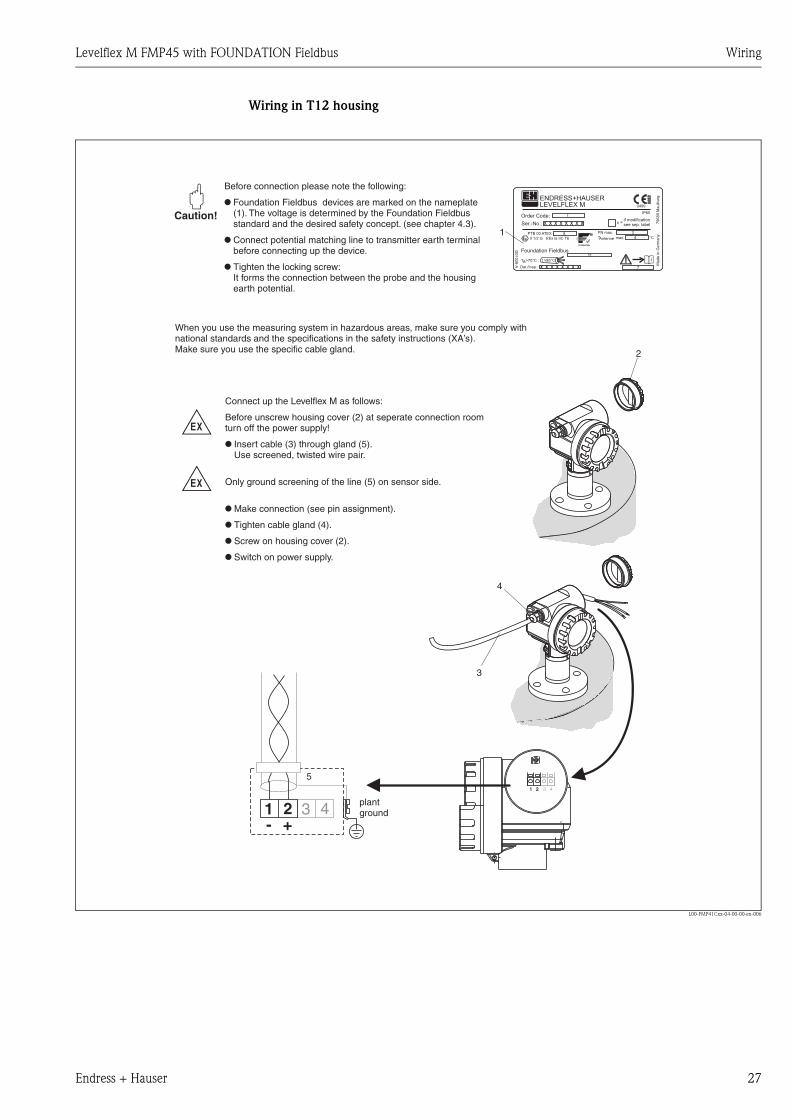
Wiring in T12 housing
L00-FMP41Cxx-04-00-00-en-006
-
-
51 2 3 4
1
"Ser.-No.:
Order Code:
D0
10
28
-A
t >85°C
x =if modificationsee sep. label
Dat./Insp.:
PN max.
TAntenne max. °C
79
68
9M
au
lbu
rgM
ad
ein
Ge
rma
ny
T >70°C :A
LEVELFLEX MENDRESS+HAUSER
PTB 00 ATEX
II 1/2 G EEx ia IIC T6
IP65
Foundation Fieldbus
x x x x x x x x
x x x x x x x x
1
3
4
11
8
7
3 41 2- +
2
4
3
When you use the measuring system in hazardous areas, make sure you comply withnational standards and the specifications in the safety instructions (XA’s).Make sure you use the specific cable gland.
Connect up the Levelflex M as follows:
Before unscrew housing cover (2) at seperate connection roomturn off the power supply!
Insert cable (3) through gland (5).Use screened, twisted wire pair.
Only ground screening of the line (5) on sensor side.
Make connection (see pin assignment).
Tighten cable gland (4).
Screw on housing cover (2).
Switch on power supply.
�
�
�
�
�
Before connection please note the following:
Foundation Fieldbus devices are marked on the nameplate(1). The voltage is determined by the Foundation Fieldbusstandard and the desired safety concept. (see chapter 4.3).
Connect potential matching line to transmitter earth terminalbefore connecting up the device.
Tighten the locking screw:It forms the connection between the probe and the housingearth potential.
�
�
�
Caution!
plantground

Wiring Levelflex M FMP45 with FOUNDATION Fieldbus
28 Endress + Hauser
Wiring with FOUNADTION Fieldbus connector
L00-FMP41Cxx-04-00-00-en-007
Cable specification FOUNDATION Fieldbus
Twisted, shielded pairs must be used. The cable specifications can be taken from the FF specification
or IEC 61158-2. The following have been found suitable:
Non-Ex-area:
• Siemens 6XV1 830-5BH10,
• Belden 3076F,
• Kerpen CEL-PE/OSCR/PVC/FRLA FB-02YS(ST)YFL.
Ex-area:
• Siemens 6XV1 830-5AH10,
• Belden 3076F,
• Kerpen CEL-PE/OSCR/PVC/FRLA FB-02YS(ST)YFL.
Fieldbus plug connectors
For the versions with fieldbus plug connector (M12 or 7/8"), the signal line can be connected
without opening the housing.
Pin assignment of the 7/8" plug connector (FOUNDATION Fieldbus plug)
L00-FMxxxxxx-04-00-00-yy-017
Pin Meaning
1 Signal -
2 Signal +
3 not connected
4 ground
-
"Made in GermanyD-79689 Maulburg
Dat./Insp.:
Order Code:
IP68 / NEMA 6PSer.-No.:
90 … 253 V AC 1VA10,5 … 36 V DC 1W10,5 … 36 V DC 0,8W
4 … 20 mA HART 2-wire4-wire
Profibus PAFoundation Fieldbus
ENDRESS+HAUSER
t >85°CTA > 70°C :
D01345-A
if modificationsee sep. labelX = Patents
LEVELFLEX-M
x
4
1
23
Before connection please note the following:
Foundation Fieldbus devices are marked on thenameplate (1). The voltage is determined by theFoundation Fieldbus standard and the desired safetyconcept (e.g. FISCO).
Connect potential matching line to transmitter earthterminal (4) before connecting up the device.
●
●
When you use the measuring system in hazardous areas, make sure you comply withnational standards and the specifications in the safety instructions (XA’s).
On devices supplied with a certificate, the explosion protectionis designed as follows:
Housing F12 - EEx ia:Power supply must be intrinsically safe (e.g. FISCO).
The electronics and the current output are galvanicallyseparated from the antenna circuit.
●
●
Caution!
The Levelflex M is connected as follows:
Insert plug (2) into bushing (3).
Screw firmly
Ground the device according to the desired safety concept.
●
●
●
2
1 3
4+
– nc
Levelflex M FMP45 with FOUNDATION Fieldbus Wiring
Endress + Hauser 29
4.2 Connecting the measuring unit
Ground connection
It is necessary to make a good ground connection to the ground terminal on the outside of the
housing, in order to achieve EMC security.
Cable gland
Cable entry
Fieldbus FOUNDATION 7/8" plug
Terminals
for wire cross-sections of 0.5...2.5 mm2
Supply voltage
The following values are the voltages across the terminals directly at the instrument:
Current consumption
Approx 13 mA for the range of voltages given above.
Overvoltage protection
If the measuring device is used for the level measurement in flammable liquids which requires the
use of an overvoltage protection according to DIN EN 60079-14, standard for testprocedures DIN
IEC 60060-1 (10 kA, Puls 8/20 μs) it has to be ensured that
• the measuring device with integrated overvoltage protection with gas discharge tubes within the
T12-enclosure is used, refer to product overview on → ä 8
or
• this protection is achieved by the use of other appropriate measures (external protection devices
e.g. HAW262Z).
Type Clamping area
Standard, EEx ia, IS Plastic M20x1.5 5...10 mm
EEx em, EEx nA Metal M20x1.5 7...10.5 mm
Type Terminal voltage
minimum maximum
standard 9 V 32 V
EEx ia (FISCO model) 9 V 17, 5 V
EEx ia (Entity concept) 9 V 24 V

Wiring Levelflex M FMP45 with FOUNDATION Fieldbus
30 Endress + Hauser
4.3 Recommended connection
For maximum EMC protection please observe the following points:
• The external ground terminal on the transmitter must be connected to ground.
• The continuity of the cable screening between tapping points must be ensured.
• If potential equalisation is present between the individual grounding points, ground the screening
at each cable end or connect it to the device housing (as short as possible).
• If there are large differences in potential between grounding points, the grounding should run via
a capacitor that is suitable for high frequency use (e.g. ceramic 10 nF/250 V&).
" Caution!
Applications, which are subject to the explosion prevention, permit only under special conditions
the repeated grounding of the protective screen , see to EN 60 079-14..
4.4 Degree of protection
• with closed housing tested according to
– IP68, NEMA6P (24 h at 1.83 m under water surface)
– IP66, NEMA4X
• with open housing: IP20, NEMA1 (also ingress protection of the display)
4.5 Post-connection check
After wiring the measuring instrument, perform the following checks:
• Is the terminal allocation correct (see → ä 26 and → ä 27)?
• Is the cable gland tight?
• Is the M12 connector screwed tight?
• Is the housing cover screwed tight?
• If auxiliary power is available:
Is the instrument ready for operation and is the liquid crystal display visible?

Levelflex M FMP45 with FOUNDATION Fieldbus Operation
Endress + Hauser 31
5 Operation
5.1 Quick operation guide
L00-FMP4xxxx-19-00-00-en-001
X XX
X
S
S S
OO O
F F
>3 s
F
...
2x
ENDRESS + HAUSER
E+–
...
...
Selection and configuration in Operation menu:
Group Selection
Function Groupunction
Note!
Selection menus:function
Typing in numerals and text:numeral / text
function
function
Group selection
Measured value display
1.) Change from Measured Value Display to by pressing
2.) Press or to select the required (e.g.. "basic setup (00)") and confirm by pressing
(e.g. "tank shape (002)") is selected.
The active selection is marked by a in front of the menu text.
3.) Activate Edit mode with or .
a) Select the required in selected (e.g. "tank shape (002)") with or .
b) confirms selection appears in front of the selected parameter
c) confirms the edited value system quits Edit mode
d) / (= ) interrupts selection system quits Edit mode
a) Press or to edit the first character of the (e.g. "empty calibr. (005)")
b) positions the cursor at the next character (a) until you have completed your input
c) if a symbol appears at the cursor, press to accept the value enteredsystem quits Edit mode
d) / (= ) interrupts the input,
4) Press to select the next (e.g. "medium property (003)")
5) Press / (= ) once return to previous (e.g. "tank shape (002)")
Press / (= ) twice return to
6) Press / (= ) to return to
F
S O
O
S O
F
S
X
S
F
S
F
F
O S X
O S
F
O X
F
O S X
O S
O X
➜ ✔
➜
➜
➜
➜
➜
➜
First f
continue with
system quits Edit mode
➜
✔
Parameter
��������
������ ����������������
���������������
�����������
����������� ����
����������
��������
� ������������
� ����������
�������������
��������
����������
��������������
Operation Levelflex M FMP45 with FOUNDATION Fieldbus
32 Endress + Hauser
5.1.1 General structure of the operating menu
The operating menu is made up of two levels:
• Function groups (00, 01, 03, …, 0C, 0D):
The individual operating options of the instrument are split up roughly into different function
groups. The function groups that are available include, e.g.: "basic setup", "safety settings.",
"output", "display", etc.
• Functions (001, 002, 003, …, 0D8, 0D9):
Each function group consists of one or more functions. The functions perform the actual operation
or parameterisation of the instrument. Numerical values can be entered here and parameters can
be selected and saved. The available functions of the “basic setup" (00) function group include,
e.g.: "tank properties" (002), "medium property" (003), "process cond." (004), "empty
calibr." (005), etc.
If, for example, the application of the instrument is to be changed, carry out the following
procedure:
1. Select the “basic setup" (00) function group.
2. Select the "tank properties" (002) function (where the existing tank shape is selected).
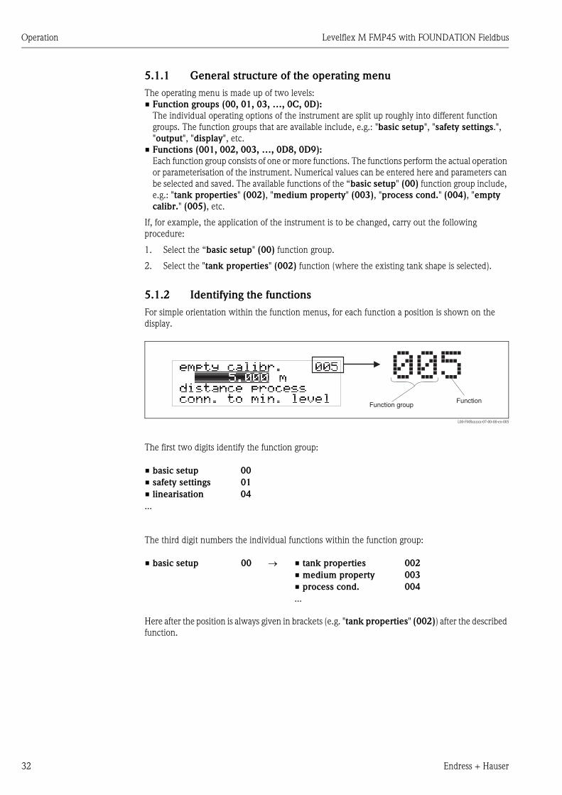
5.1.2 Identifying the functions
For simple orientation within the function menus, for each function a position is shown on the
display.
L00-FMRxxxxx-07-00-00-en-005
The first two digits identify the function group:
The third digit numbers the individual functions within the function group:
Here after the position is always given in brackets (e.g. "tank properties" (002)) after the described
function.
• basic setup 00
• safety settings 01
• linearisation 04
...
• basic setup 00 → • tank properties 002
• medium property 003
• process cond. 004
...
Levelflex M FMP45 with FOUNDATION Fieldbus Operation
Endress + Hauser 33
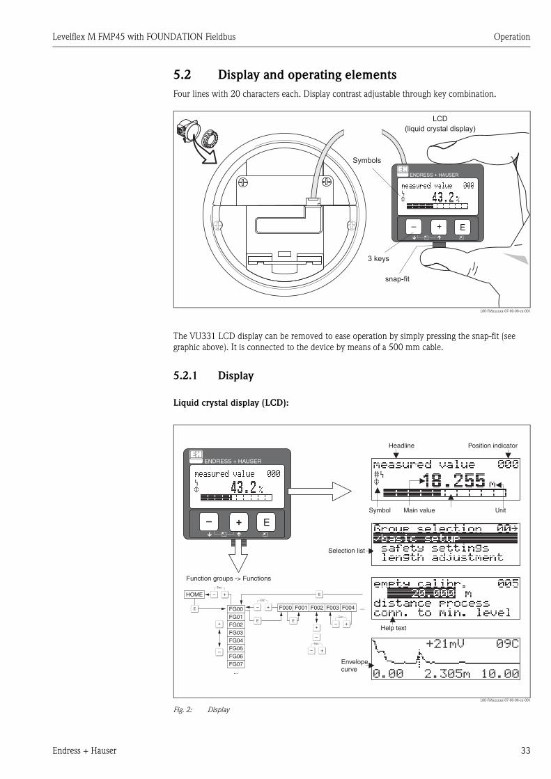
5.2 Display and operating elements
Four lines with 20 characters each. Display contrast adjustable through key combination.
L00-FMxxxxxx-07-00-00-en-001
The VU331 LCD display can be removed to ease operation by simply pressing the snap-fit (see
graphic above). It is connected to the device by means of a 500 mm cable.
5.2.1 Display
Liquid crystal display (LCD):
L00-FMxxxxxx-07-00-00-en-001
Fig. 2: Display
ENDRESS + HAUSER
E+–
ENDRESS+HAUSER
MICROPILOT II
ENDRESS+HAUSER
MICROPILOT II
IP 65IP 65
Order Code:Ser.-No.:
Order Code:Ser.-No.:
MessbereichMeasuring range
MessbereichMeasuring rangeU 16...36 V DC
4...20 mA
U 16...36 V DC
4...20 mA
max. 20 m
max. 20 m
Made
inG
erm
any
Maulb
urg
Made
inG
erm
any
Maulb
urg
T>70°C :
A
t >85°C
T>70°C :
A
t >85°C
LCD(liquid crystal display)
Symbols
3 keys
snap-fit
XX
X
XS
S
OO FF
F
F
HOME
FG00 F000 F001 F002 F003 F004 ...
FG01FG02FG03FG04FG05FG06FG07
...
�� �! "#$
"�""��%"&�"�""
ENDRESS + HAUSER
E+–
Headline Position indicator
Main value UnitSymbol
Selection list
Function groups -> Functions
Help text
Envelopecurve

Operation Levelflex M FMP45 with FOUNDATION Fieldbus
34 Endress + Hauser
5.2.2 Display symbols
The following table describes the symbols that appear on the liquid crystal display:
5.2.3 Key assignment
The operating elements are located inside the housing and are accessible for operation by opening
the lid of the housing.
Function of the keys
Sybmol Meaning
ALARM_SYMBOL
This alarm symbol appears when the instrument is in an alarm state. If the symbol flashes, this indicates a
warning.
LOCK_SYMBOL
This lock symbol appears when the instrument is locked,i.e. if no input is possible.
COM_SYMBOL
This communication symbol appears when a data transmission via e.g. HART, PROFIBUS PA or
FOUNDATION Fieldbus is in progress.
SIMULATION_SWITCH_ENABLE
This communication symbol appears when simulation in FOUNDATION Fieldbus is enabled via the DIP
switch.
Key(s) Meaning
O or V Navigate upwards in the selection list
Edit numeric value within a function
S or W Navigate downwards in the selection list
Edit numeric value within a function
X or Z Navigate to the left within a function group
For M Navigate to the right within a function group, confirmation.
O and For
S and F
Contrast settings of the LCD
O and S and F
Hardware lock / unlock
After a hardware lock, an operation of the instrument via display or
communication is not possible!
The hardware can only be unlocked via the display. An unlock parameter must
be entered to do so.
Levelflex M FMP45 with FOUNDATION Fieldbus Operation
Endress + Hauser 35
5.3 Local operation
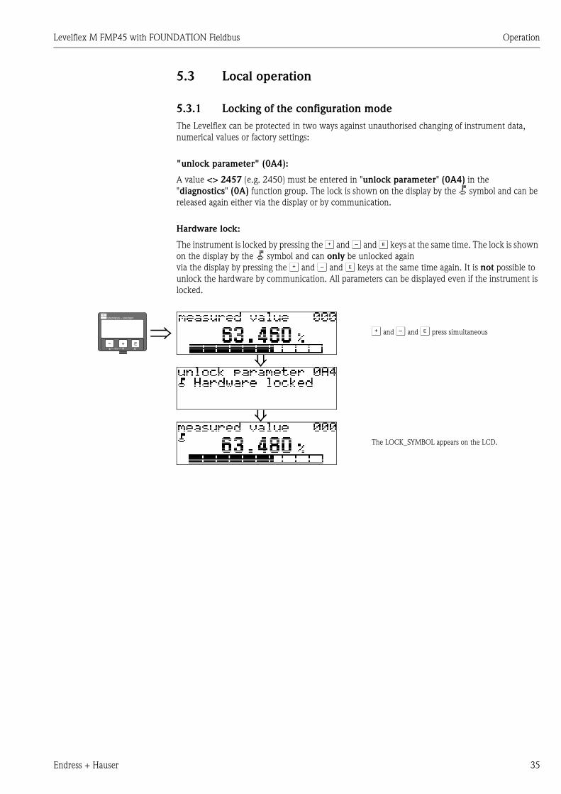
5.3.1 Locking of the configuration mode
The Levelflex can be protected in two ways against unauthorised changing of instrument data,
numerical values or factory settings:
"unlock parameter" (0A4):
A value <> 2457 (e.g. 2450) must be entered in "unlock parameter" (0A4) in the
"diagnostics" (0A) function group. The lock is shown on the display by the symbol and can be
released again either via the display or by communication.
Hardware lock:
The instrument is locked by pressing the O and S and F keys at the same time. The lock is shown
on the display by the symbol and can only be unlocked again
via the display by pressing the O and S and F keys at the same time again. It is not possible to
unlock the hardware by communication. All parameters can be displayed even if the instrument is
locked.
⇒ O and S and F press simultaneous
⇓
⇓The LOCK_SYMBOL appears on the LCD.
ENDRESS + HAUSER
E+–
Operation Levelflex M FMP45 with FOUNDATION Fieldbus
36 Endress + Hauser
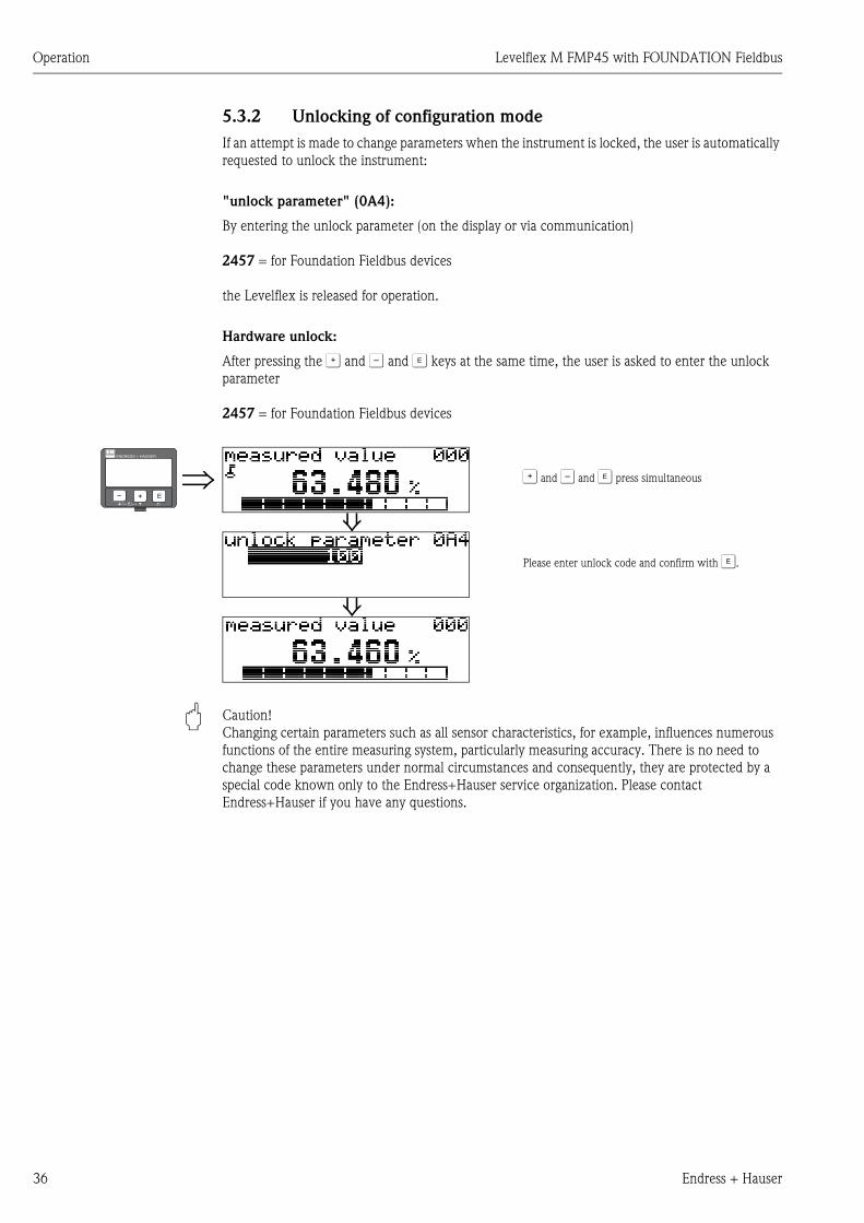
5.3.2 Unlocking of configuration mode
If an attempt is made to change parameters when the instrument is locked, the user is automatically
requested to unlock the instrument:
"unlock parameter" (0A4):
By entering the unlock parameter (on the display or via communication)
2457 = for Foundation Fieldbus devices
the Levelflex is released for operation.
Hardware unlock:
After pressing the O and S and F keys at the same time, the user is asked to enter the unlock
parameter
2457 = for Foundation Fieldbus devices
" Caution!
Changing certain parameters such as all sensor characteristics, for example, influences numerous
functions of the entire measuring system, particularly measuring accuracy. There is no need to
change these parameters under normal circumstances and consequently, they are protected by a
special code known only to the Endress+Hauser service organization. Please contact
Endress+Hauser if you have any questions.
⇒ O and S and F press simultaneous
⇓Please enter unlock code and confirm with F.
⇓
ENDRESS + HAUSER
E+–

Levelflex M FMP45 with FOUNDATION Fieldbus Operation
Endress + Hauser 37
5.3.3 Factory settings (Reset)
" Caution!
A reset sets the instrument back to the factory settings. This can lead to an impairment of the
measurement. Generally, you should perform a basic setup again following a reset.
A reset is only necessary:
• if the instrument no longer functions
• if the instrument must be moved from one measuring point to another
• if the instrument is being de-installed /put into storage/installed
User input ("reset" (0A3)):
• 33 333 = customer parameters
333 = reset customer parameters
This reset is recommended whenever an instrument with an unknown 'history' is to be used in an
application:
• The Levelflex is reset to the default values.
• The customer specific tank map is not deleted.
• The mapping can also be deleted in the "cust. tank map" (055) function of the "extended
calibr" (05) function group.
• A linearisation is switched to "linear" although the table values are retained. The table can be
reactivated in the "linearisation" (04) function group.
List of functions that are affected by a reset:
A complete “basic setup" (00) must be activated.
⇒ENDRESS + HAUSER
E+–
• tank properties (002)
• medium cond. (003)
• process proper. (004)
• empty calibr. (005)
• full calibr. (006)
• output on alarm (010)
• output on alarm (011)
• outp. echo loss (012)
• ramp %span/min (013)
• delay time (014)
• safety distance. (015)
• in safety dist. (016)
• overspill protection (018)
• end of probe (030)
• level/ullage (040)
• linearisation (041)
• customer unit (042)
• max. scale (046)
• diameter vessel (047)
• check distance (051)
• range of mapping (052)
• start mapping (053)
• offset (057)
• output damping (058)
• low output limit (062)
• curr. output mode (063)
• fixed cur. value (064)
• 4mA value (068)
• language (092)
• back to home (093)
• format display (094)
• no of decimals (095)
• sep. character (096)
• unlock parameter (0A4)
Operation Levelflex M FMP45 with FOUNDATION Fieldbus
38 Endress + Hauser
5.4 Display and acknowledging error messages
Type of error
Errors that occur during commissioning or measuring are displayed immediately on the local
display. If two or more system or process errors occur, the error with the highest priority is the one
shown on the display.
The measuring system distinguishes between two types of error:
• A (Alarm):
Instrument goes into a defined state (e.g. MAX 22 mA)
Indicated by a constant symbol.
(For a description of the codes see → ä 82)
• W (Warning):
Instrument continue measuring, error message is displayed.
Indicated by a flashing symbol.
(For a description of the codes see → ä 82)
• E (Alarm / Warning):
Configurable (e.g. loss of echo, level within the safety distance)
Indicated by a constant/flashing symbol.
(For a description of the codes see → ä 82)
Error messages
Error messages appear as four lines of plain text on the display. In addition, a unique error code is
also output. A description of the error codes is given on → ä 82.
• The "diagnostics" (0A) function group can display current errors as well as the last errors that
occurred.
• If several current errors occur, use O or S to page through the error messages.
• The last occurring error can be deleted in the "diagnostics" (0A) function group
with the function "clear last error" (0A2).
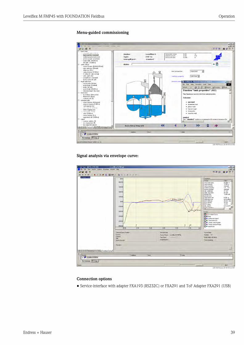
5.4.1 ToF Tool operating program
The ToF Tool is a graphical operation software for instruments from Endress+Hauser. It is used to
support commissioning, securing of data, signal analysis and documentation of the instruments. It
is compatible with the following operating systems: WinNT4.0, Win2000 and WinXP.
The ToF Tool supports the following functions:
• Online configuration of transmitters
• Signal analysis via envelope curve
• Linearisation table (graphically supported creation, editing, importing and exporting)
• Loading and saving of instrument data (Upload/Download)
• Documentation of measuring point
! Note!
Further information you may find on the CD-ROM, which is enclosed to the instrument.
⇒ENDRESS + HAUSER
E+–
Levelflex M FMP45 with FOUNDATION Fieldbus Operation
Endress + Hauser 39
Menu-guided commissioning
L00-FMP4xxxx-20-00-00-de-002
Signal analysis via envelope curve:
L00-FMP4xxxx-20-00-00-de-007
Connection options
• Service-interface with adapter FXA193 (RS232C) or FXA291 and ToF Adapter FXA291 (USB)

Operation Levelflex M FMP45 with FOUNDATION Fieldbus
40 Endress + Hauser
5.5 FOUNDATION Fieldbus communication
5.5.1 System architecture
The following diagram shows two typical examples of a FOUNDATION Fieldbus network with the
associated components.
L00-FMxxxxxx-14-00-06-xx-001
Fig. 3: FOUNDATION Fieldbus-HSE: High Speed Ethernet, FOUNDATION Fieldbus-H1: FOUNDATION Fieldbus-
H1, LD: Linking Device FOUNDATION Fieldbus-HSE/FOUNDATION Fieldbus-H1,
PS: Bus Power Supply, SB: Safety Barrier, BT: Bus Terminator
The system can be connected in the following ways:
– A linking device makes the connection to higher-order fieldbus levels (e.g. High Speed Ethernet (HSE)) possible.
– An FOUNDATION Fieldbus-H1 connecting card is needed for direct connection to a process control system.
! Note!
Further information on FOUNDATION Fieldbus can be found in Operating Instructions BA013S
"FOUNDATION Fieldbus Overview, Installation and Commissioning Guidelines", the
FOUNDATION Fieldbus Specification or on the Internet at "http://www. fieldbus.org".
FOUNDATION Fieldbus-H1
FOUNDATION Fieldbus-H1
BT
BT
PS
PS
BT
SB
BT
FOUNDATION Fieldbus-HSE
Industrial Network
LD
Levelflex M
Levelflex M
Prosonic M
Prosonic M
Micropilot M
Micropilot M
Gammapilot M
Gammapilot M
Levelflex M FMP45 with FOUNDATION Fieldbus Operation
Endress + Hauser 41
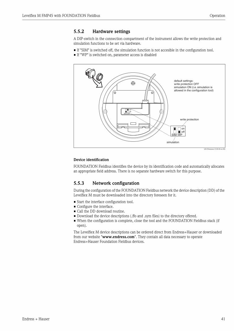
5.5.2 Hardware settings
A DIP-switch in the connection compartment of the instrument allows the write protection and
simulation functions to be set via hardware.
• If "SIM" is switched off, the simulation function is not accesible in the configuration tool.
• If "WP" is switched on, parameter access is disabled
L00-FMxxxxxx-19-00-00-en-002
Device identification
FOUNDATION Fieldbus identifies the device by its identification code and automatically allocates
an appropriate field address. There is no separate hardware switch for this purpose.
5.5.3 Network configuration
During the configuration of the FOUNDATION Fieldbus network the device description (DD) of the
Levelflex M must be downloaded into the directory foreseen for it.
• Start the interface configuration tool.
• Configure the interface.
• Call the DD download routine.
• Download the device descriptions (.ffo and .sym files) to the directory offered.
• When the configuration is complete, close the tool and the FOUNDATION Fieldbus stack (if
open).
The Levelflex M device descriptions can be ordered direct from Endress+Hauser or downloaded
from our website "www.endress.com". They contain all data necessary to operate
Endress+Hauser Foundation Fieldbus devices.
ENDRESS+HAUSER
MICROPILOT II
ENDRESS+HAUSER
MICROPILOT II
IP 65IP 65
Order Code:Ser.-No.:
Order Code:Ser.-No.:
MessbereichMeasuring range
MessbereichMeasuring rangeU 16...36 V DC
4...20 mA
U 16...36 V DC4...20 mA
max. 20 m
max. 20 m
Made in
Germ
any
M
aulb
urg
Made in
Germ
any
M
aulb
urg
T>70°C :
A
t >85°C
T>70°C :
A
t >85°C
onoff
SIM WP
SIM WPoffon
simulation
write protection
default settings:write protection OFFsimulation ON (i.e. simulation isallowed in the configuration tool)
Operation Levelflex M FMP45 with FOUNDATION Fieldbus
42 Endress + Hauser
Example: Start-up using the NI-Fieldbus configurator
Start the bus configuration tool. After start-up, the tool shows the network configuration in the form
of an expandable tree. If the Levelflex M has been connected correctly, it can now be identified:
A double click on the name reveals the device data:
The device ID is made up of the following components:
whereby:
A right-hand mouse click on the name opens up a menu from which the PD_TAG and
NODE_ADDRESS can be changed
A click on the name expands the device tree to show the function blocks available for it:
E+H_LEVELFLEX_M_XXXXXXXX
PD_TAG the physical name of the device
DEVICE_ID the unique device identifier
NODE_ADDRESS the fieldbus node to which the device is connected (is automatically allocated by the
Configurator)
Device_ID = 452B481012-XXXXXXXX
452B48 ID code for Endress+Hauser
1012 ID code for Levelflex M
XXXXXXXX Device serial number, as printed on the nameplate
E+H_LEVELFLEX_M_XXXXXXXX
RESOURCE_XXXXXX (RB2)
SENSOR_XXXXXX (TBGRL)
DIAGNOSTIC_BLOCK_XXXXXX (DIAG)
DISPLAY_BLOCK-XXXXXX (DISP)
ANALOG_INPUT_1_XXXXXX (AI)
ANALOG_INPUT_2_XXXXXX (AI)
PID_XXXXXX(PID)
AR_XXXXXX (AR)
IS_XXXXXX (IS)
SC_XXXXXX (SC)
IT_XXXXXX (IT)
Levelflex M FMP45 with FOUNDATION Fieldbus Operation
Endress + Hauser 43
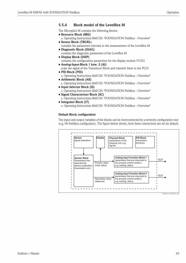
5.5.4 Block model of the Levelflex M
The Micropilot M contains the follwoing blocks:
• Resource Block (RB2)
s. Operating Instructions BA013S: "FOUNDATION Fieldbus - Overview"
• Sensor Block (TBGRL)
contains the parameters relevant to the measurement of the Levelflex M
• Diagnostic Block (DIAG)
contains the diagnostic parameters of the Levelflex M
• Display Block (DISP)
contains the configuration parameters for the display module VU331
• Analog-Input-Block 1 bzw. 2 (AI)
scale the signal of the Transducer Block and transmit them to the PLCS
• PID Block (PID)
s. Operating Instructions BA013S: "FOUNDATION Fieldbus - Overview"
• Arithmetic Block (AR)
s. Operating Instructions BA013S: "FOUNDATION Fieldbus - Overview"
• Input Selector Block (IS)
s. Operating Instructions BA013S: "FOUNDATION Fieldbus - Overview"
• Signal Characterizer Block (SC)
s. Operating Instructions BA013S: "FOUNDATION Fieldbus - Overview"
• Integrator Block (IT)
s. Operating Instructions BA013S: "FOUNDATION Fieldbus - Overview"
Default Block configuration
The input and output variables of the blocks can be interconnected by a network configuration tool
(e.g. NI-Fieldbus configurator). The figure below shows, how these connections are set by default.
L00-FMxxxxxx-02-00-00-en-002
OUT
OUT
Physical Blockparameters of thephysical unit, e.g.tag No.
DisplaySensorsignal evaluation
Sensor BlockParameters thatdescribe thedevice (calibration,linearisation etc.)
Analog Input Function Block 1parameters that are important tothe process control system,e.g. scaling, status
Analog Input Function Block 2parameters that are important tothe process control system,e.g. scaling, status
PID BlockAutomationfunctions
Primary value(main value)
Secondary value(distance)

Operation Levelflex M FMP45 with FOUNDATION Fieldbus
44 Endress + Hauser
5.5.5 Resource block
The resource block contains the parameters used to describe physical resources of the device. It has
no linkable inputs or outputs.
Operation
The resource block is opened by a click on the resource line.
If the NI-FBUS Configurator is being used, a series of file tabs appears on the screen. The files can
be opened to view and/or edit the parameters in the following table. A short description of the
parameter function appears on the side of the screen. A change in the parameter is stored by pressing
the WRITE CHANGES button when the block is out of service. Press the READ ALL button to check
the values stored in the device.
Parameters
The function of the resource block parameters not described here can can be taken from the
FOUNDATION Fieldbus specification, see "www.fieldbus.org".
Parameter Description
TAG_DESC User description of the intended application of the block.
MODE_BLK Lists the actual, target, permitted and normal operating modes of the block.
– Target: changes the operating mode of the block
– Actual: indicates the current operating mode of the block
– Permitted: states which operating modes are allowed
– Normal: indicates the normal operating mode of the block
The possible operating modes of the resources block are:
– AUTO: the block is operating as normal
– OOS: the block is out of service.
If the resource block is out of service, then all blocks within the device (resource) are
forced into the same status.
RS_STATE Indicates the state of the resource block application state machine
– On-line: block in AUTO mode
– Standby: block in OOS mode
WRITE_LOCK Indicates the status of DIP-switch WP
– LOCKED: device data can be modified
– NOT LOCKED: device data can be modified
RESTART Allows a manual restart:
– UNINITIALISED: no status
– RUN: normal operational status
– RESOURCE: resets the resource block parameters
– DEFAULTS: Resets all FOUNDATION Fieldbus parameters within the
device, but not the manufacturer specific parameters.
– PROCESSOR: make a warm start of the processor
BLOCK_ERROR Shows error status of software and hardware components
– Out-of-Service: the block is in OOS mode
– Simulation active: shows the setting of DIP-switch SIM
BLOCK_ALM Shows any configuration, hardware, connection and system problems in the lock. The
cause of the alert is to be seen in the subcode field.
Levelflex M FMP45 with FOUNDATION Fieldbus Operation
Endress + Hauser 45
5.5.6 Sensor Block
The Sensor Block contains the parameters required to calibrate the device. These parameters can
also be addressed by using the VU331 display module. The calibration of the device is described in
Chapter 6.
Operation
Parameter changes from the tool are made off-line while the device is operating. The changes are
downloaded by first setting MODE_BLK = OOS then pressing the WRITE CHANGES button. In
order to resume operation, change MODE-BLK to AUTO 1)).
Block administration parameters
Output values
Configuration parameters
The Sensor block also contains the configuration parameters, which are used to commission and
calibrate the instrument. They are identical to the functions of the operating menu, except for the
service parameters which are not accessible on the bus. Thus, the calibration procedure via the
display module (Chapter 6.4) is equally valid for a calibration via a network configuration tool.
A complete list of the configuration parameters can be found in the "Description of Instrument
Functions", BA245F/00/en.
1) If MODE_BLK refuses to be changed to AUTO, an error is present. Control all parameters, perform the required changes and try again to change MODE_BLK
to AUTO.
Parameter Description
MODE_BLK See description in Resource block. The possible operating modes of the Sensor block are:
– AUTO: the block is operating as normal
– OOS: the block is out of service.
TAG_DESC User description of the intended application of the block.
BLOCK_ERROR Shows error status of software and hardware components
– Out-of-Service: the block is in OOS mode
Parameter Description
PRIMARY_VALUE Main value (level or volume).
SECONDARY_VALUE Measured distance.
Operation Levelflex M FMP45 with FOUNDATION Fieldbus
46 Endress + Hauser
Methods
The FOUNDATION Fieldbus specification provides for the use of so-called methods to simplify the
operation of the device. A method is an interactive sequence of steps that must be followed in order
to obtain a particular function from the device.
The Levelflex M has got the following methods:
• Basic setup
• Safety settings
• Acknowledge alarm
• Length adjustment
• Linearisation
• Extended calibration
• Output
• System parameters
• Lock TB Manufacturer parameters
Most of these methods are identical to the respective function group in the operating menu. A
detailed description of them can be found in the "Description of Instrument functions", BA245F/
00/en.
Parameter list of the Levelflex M Sensor Block
Parameter Position
Indicator
rel.
Index
Variable Name Size
[bytes]
Type Access Storage
Class
Changeable
in Mode
measured value 000 18 PARMEASUREDVALUE 4 FloatingPoint RO dynamic Auto, OOS
tank properties 002 19 PARTANKPROPERTIES 1 Unsigned8 RW static OOS
medium property 003 20 PARMEDIUMCONDITION 1 Unsigned8 RW static OOS
process propert. 004 21 PARPROCESSPROPERTIES 1 Unsigned8 RW static OOS
end of probe 030 22 PARENDOFPROBE 1 Unsigned8 RW static OOS
probe length 031 23 PARPROBESHORTEND 1 Unsigned8 RW dynamic OOS
probe 032 24 PARPROBEFREE 1 Unsigned8 RW dynamic OOS
probe length 033 25 PARPROBELENGTH 4 FloatingPoint RW static OOS
determine length 034 26 PARPROBELENGTHSETUP 1 Unsigned8 RW dynamic OOS
empty calibr. 005 27 PAREMPTYCALIBRATION 4 FloatingPoint RW static OOS
full calibr. 006 28 PARFULLCALIBRATION 4 FloatingPoint RW static OOS
echo quality 056 29 PARECHOQUALITY 2 Integer16 RO dynamic Auto, OOS
check distance 051 30 PARCHECKDISTANCE 1 Unsigned8 RW dynamic OOS
range of mapping 052 31 PARSUPPRESSIONDISTANCE 4 FloatingPoint RW dynamic OOS
start mapping 053 32 PARSTARTMAPPINGRECORD 1 Unsigned8 RW dynamic OOS
pres. map dist. 054 33 PARPRESMAPRANGE 4 FloatingPoint RO dynamic Auto, OOS
delete mapping 055 34 PARDELETEMAPPING 1 Unsigned8 RW dynamic OOS
offset 057 35 PAROFFSETOFMEASUREDDISTANCE 4 FloatingPoint RW static OOS
output damping 058 36 PAROUTPUTDAMPING 4 FloatingPoint RW static Auto, OOS
upper block.dist 059 37 PARHIGHBLOCKINGDISTANCE 4 FloatingPoint RW static OOS
output on alarm 010 38 PAROUTPUTONALARM 1 Unsigned8 RW static OOS
outp. echo loss 012 39 PARREACTIONLOSTECHO 1 Unsigned8 RW static OOS
ramp %span/min 013 40 PARRAMPINPERCENTPERMIN 4 FloatingPoint RW static OOS
delay time 014 41 PARDELAYTIMEONLOSTECHO 2 Unsigned16 RW static OOS
safety distance 015 42 PARLEVELWITHINSAFETYDISTANCE 4 FloatingPoint RW static OOS
in safety dist. 016 43 PARINSAFETYDISTANCE 1 Unsigned8 RW static OOS
Levelflex M FMP45 with FOUNDATION Fieldbus Operation
Endress + Hauser 47
ackn. alarm 017 44 PARACKNOWLEDGEALARM 1 Unsigned8 RW dynamic Auto, OOS
broken probe det 019 45 PARBROKENPROBEDETECTION 1 Unsigned8 RW static OOS
level/ullage 040 46 PARLEVELULLAGEMODE 1 Unsigned8 RW static OOS
linearisation 041 47 PARLINEARISATION 1 Unsigned8 RW static OOS
customer unit 042 48 PARCUSTOMERUNIT 2 Unsigned16 RW static OOS
table no. 043 49 PARTABLENUMBER 1 Unsigned8 RW non-vol. Auto, OOS
input level 044 50 PARINPUTLEVELHALFAUTOMATIC 4 FloatingPoint RO dynamic Auto, OOS
input level 044 51 PARINPUTLEVELMANUAL 4 FloatingPoint RW dynamic OOS
input volume 045 52 PARINPUTVOLUME 4 FloatingPoint RW dynamic OOS
max. scale 046 53 PARMAXVOLUME 4 FloatingPoint RW static OOS
diameter vessel 047 54 PARCYLINDERVESSEL 4 FloatingPoint RW static OOS
simulation 065 55 PARSIMULATION 1 Unsigned8 RW dynamic OOS
simulation value 066 56 PARSIMULATIONVALUELEVEL 4 FloatingPoint RW dynamic Auto, OOS
simulation value 066 57 PARSIMULATIONVALUEVOLUME 4 FloatingPoint RW dynamic Auto, OOS
unlock parameter 0A4 58 PAROPERATIONCODE 2 Unsigned16 RW non-vol. OOS
measured dist. 0A5 59 PARMEASUREDDISTANCE 4 FloatingPoint RO dynamic Auto, OOS
measured level 0A6 60 PARMEASUREDLEVEL 4 FloatingPoint RO dynamic Auto, OOS
detection window 0A7 61 PARDETECTIONWINDOW 1 Unsigned8 RW dynamic OOS
application par. 0A8 62 PARAPPLICATIONPARAMETER 1 Unsigned8 RO dynamic Auto, OOS
distance unit 0C5 63 PARDISTANCEUNIT 2 Unsigned16 RW static OOS
download mode 0C8 64 PARDOWNLOADMODE 1 Unsigned8 RW static OOS
max meas dist 0D84 65 PARABSMAXMESSDIST 4 FloatingPoint RO dynamic Auto, OOS
max sample dist. 0D88 66 PAREDITRANGEMAXSAMPLEDIST 4 FloatingPoint RO dynamic Auto, OOS
present error 0A0 67 PARACTUALERROR 2 Unsigned16 RO dynamic Auto, OOS
Parameter Position
Indicator
rel.
Index
Variable Name Size
[bytes]
Type Access Storage
Class
Changeable
in Mode
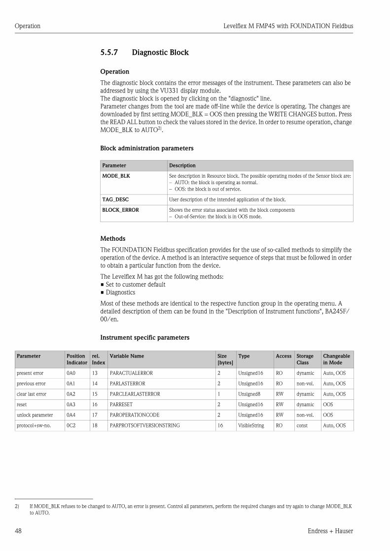
Operation Levelflex M FMP45 with FOUNDATION Fieldbus
48 Endress + Hauser
5.5.7 Diagnostic Block
Operation
The diagnostic block contains the error messages of the instrument. These parameters can also be
addressed by using the VU331 display module.
The diagnostic block is opened by clicking on the "diagnostic" line.
Parameter changes from the tool are made off-line while the device is operating. The changes are
downloaded by first setting MODE_BLK = OOS then pressing the WRITE CHANGES button. Press
the READ ALL button to check the values stored in the device. In order to resume operation, change
MODE_BLK to AUTO2).
Block administration parameters
Methods
The FOUNDATION Fieldbus specification provides for the use of so-called methods to simplify the
operation of the device. A method is an interactive sequence of steps that must be followed in order
to obtain a particular function from the device.
The Levelflex M has got the following methods:
• Set to customer default
• Diagnostics
Most of these methods are identical to the respective function group in the operating menu. A
detailed description of them can be found in the "Description of Instrument functions", BA245F/
00/en.
Instrument specific parameters
2) If MODE_BLK refuses to be changed to AUTO, an error is present. Control all parameters, perform the required changes and try again to change MODE_BLK
to AUTO.
Parameter Description
MODE_BLK See description in Resource block. The possible operating modes of the Sensor block are:
– AUTO: the block is operating as normal.
– OOS: the block is out of service.
TAG_DESC User description of the intended application of the block.
BLOCK_ERROR Shows the error status associated with the block components
– Out-of-Service: the block is in OOS mode.
Parameter Position
Indicator
rel.
Index
Variable Name Size
[bytes]
Type Access Storage
Class
Changeable
in Mode
present error 0A0 13 PARACTUALERROR 2 Unsigned16 RO dynamic Auto, OOS
previous error 0A1 14 PARLASTERROR 2 Unsigned16 RO non-vol. Auto, OOS
clear last error 0A2 15 PARCLEARLASTERROR 1 Unsigned8 RW dynamic Auto, OOS
reset 0A3 16 PARRESET 2 Unsigned16 RW dynamic OOS
unlock parameter 0A4 17 PAROPERATIONCODE 2 Unsigned16 RW non-vol. OOS
protocol+sw-no. 0C2 18 PARPROTSOFTVERSIONSTRING 16 VisibleString RO const Auto, OOS
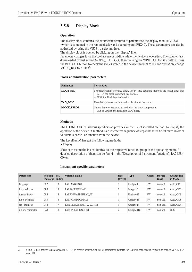
Levelflex M FMP45 with FOUNDATION Fieldbus Operation
Endress + Hauser 49
5.5.8 Display Block
Operation
The display block contains the parameters required to parametrise the display module VU331
(which is contained in the remote display and operating unit FHX40). These parameters can also be
addressed by using the VU331 display module.
The display block is opened by clicking on the "display" line.
Parameter changes from the tool are made off-line while the device is operating. The changes are
downloaded by first setting MODE_BLK = OOS then pressing the WRITE CHANGES button. Press
the READ ALL button to check the values stored in the device. In order to resume operation, change
MODE_BLK to AUTO3).
Block administration parameters
Methods
The FOUNDATION Fieldbus specification provides for the use of so-called methods to simplify the
operation of the device. A method is an interactive sequence of steps that must be followed in order
to obtain a particular function from the device.
The Levelflex M has got the following methods:
• Display
Most of these methods are identical to the respective function group in the operating menu. A
detailed description of them can be found in the "Description of Instrument functions", BA245F/
00/en.
Instrument specific parameters
3) If MODE_BLK refuses to be changed to AUTO, an error is present. Control all parameters, perform the required changes and try again to change MODE_BLK
to AUTO.
Parameter Description
MODE_BLK See description in Resource block. The possible operating modes of the sensor block are:
– AUTO: the block is operating as normal.
– OOS: the block is out of service.
TAG_DESC User description of the intended application of the block.
BLOCK_ERROR Shows the error status associated with the block components
– Out-of-Service: the block is in OOS mode.
Parameter Position
Indicator
rel.
Index
Variable Name Size
[bytes]
Type Access Storage
Class
Changeable
in Mode
language 092 13 PARLANGUAGE 1 Unsigned8 RW non-vol. Auto, OOS
back to home 093 14 PARBACKTOHOME 2 Integer16 RW non-vol. Auto, OOS
format display 094 15 PARFORMATDISPLAY_FT 1 Unsigned8 RW non-vol. Auto, OOS
no.of decimals 095 16 PARNOOFDECIMALS 1 Unsigned8 RW non-vol. Auto, OOS
sep. character 096 17 PARSEPARATIONCHARACTER 1 Unsigned8 RW non-vol. Auto, OOS
unlock parameter 0A4 18 PAROPERATIONCODE 2 Unsigned16 RW non-vol. OOS

Operation Levelflex M FMP45 with FOUNDATION Fieldbus
50 Endress + Hauser
5.5.9 Analog input block
The analog input block conditons the signal output by the Sensor block and outputs signal to the
PCL or other function blocks.
L00-FMR2xxxx-05-00-00-en-008
Operation
The resource block is opened by a click on the resource line.
Parameter changes from the tool are made off-line while the device is operating. The changes are
downloaded by first setting MODE_BLK = OOS then pressing the WRITE CHANGES button. Press
the READ ALL button to check the values stored in the device. Normally operation is resumed as
soon as MODE-BLK is set to AUTO.
Block administration parameters
Parameter Description
MODE_BLK See description in Resource block. The possible operating modes of the Sensor block are:
– AUTO: the block is operating as normal
– MAN: the block is operated with a manually entered primary value.
– OOS: the block is out of service.
TAG_DESC User description of the intended application of the block.
BLOCK_ERROR Shows error status of software and hardware components
– Out-of-Service: the block is in OOS mode
– Simulation active: shows the setting of DIP-switch SIM. Input failure/process variable
has BAD status.
– configuration error

Levelflex M FMP45 with FOUNDATION Fieldbus Operation
Endress + Hauser 51
Output values
Scaling parameters
The relationship between the output values and scaling paramaters for the Levelflex M is as follows:
The L_TYPE parameter influences the signal conversion:
• Direct:
• Indirect:
• Indirect square root:
Parameter Description
PV Either the primary/secondary Sensor block value used to execute the block or a process
value associated with it. Comprises value and status.
OUT The primary value output as a result of executing the analog input block. Comprises
value and status.
FIELD_VALUE Raw value of field device in % of PV range with a status reflecting the Sensor condition
before signal characterisation L_Type or filtering V_TIME. Comprises value and status.
Parameter Description
CHANNEL Selects the measured value to be input to the analogue input block
– 0 = no channel defined
– 1 = primary value: measured level/volume
– 2 = secondary value: measured distance
XD_SCALE Scales the Sensor block value in the required engineering units (EU).
OUT_SCALE Scales the output value in the required engineering units (EU).
L_TYPE Sets the linearization type:
– DIRECT: the Sensor block value bypasses the scaling functions
– INDIRECT:the Sensor block value is fed through the linear scaling functions
– INDIRECT SQRT: the Sensor block value is fed through the square root scaling
functions
MIN_SCALE_XDMAX_SCALE_XDMIN_SCALE_XDVALUE_CHANNEL
100VAL_FIELD−−×=
PV = CHANNEL_VALUE
( ) MIN_SCALE_OUTMIN_SCALE_OUTMAX_SCALE_OUT100
VALUE_FIELDPV +−×=
( ) MIN_SCALE_OUTMIN_SCALE_OUTMAX_SCALE_OUT100
VALUE_FIELDPV +−×=
Operation Levelflex M FMP45 with FOUNDATION Fieldbus
52 Endress + Hauser
Output response parameters
Alarm parameters
Alarm priorities
Alarm status
Parameter Description
LOW_CUT Not relevant to level measurement!
Determines a threshold for square root linearization below which the output value is set
to zero.
PV_FTIME Sets the time constant for the output value.
Parameter Description
ACK_OPTION Sets the way in which alarms and warnings are to be acknowledged.
ALARM_HYS Sets the hysteresis (in output engineering units) for all configured alarms.
A hysteresis of e.g. 2% on a HI_HI_LIMIT of 95% would cause the alarm to activate
when the level reaches 95% and to deactivate when the level drops below 93%.
A hysteresis of e.g. 2% on a LO_LO_LIMIT of 5% would cause the alarm to activate
when the level drops below 5% and to deactivate when the level rises to 7%.
HI_HI_PRI The priority (1 – 15) of the HI_HI alarm
HI_HI_LIM Sets the HI_HI alarm limit in output engineering units
HI_PRI The priority (1 – 15) of the HI alarm
HI_LIM Sets the HI warning limit in output engineering units
LO_PRI The priority (1 – 15) of the LO alarm
LO_LIM Sets the LO warning limit in output engineering units
LO_LO_PRI The priority (1 – 15) of the LO_LO alarm
LO_LO_LIM Sets the LO_LO alarm limit in output engineering units
Parameter Description
0 Alarm is suppressed
1 Recognised by the system but not reported
2 Reported to the operator, but does not require his attention
3 - 7 Advisroy alarms of increasing priority
8 - 15 Critical alarms of increasing priority
Parameter Description
HI_HI_ALM The status of the HI_HI alarm
HI_ALM The status of the HI alarm
LO_ALM The status of the LO alarm
LO_LO_ALM The status of the LO_LO alarm

Levelflex M FMP45 with FOUNDATION Fieldbus Operation
Endress + Hauser 53
Simulation
The SIMULATE parameter allows the Sensor block output value to be simulated, provided
simulation has also been enabled at the device DIP switch. The simulation must be enabled, a value
and/or status entered and the block must be in AUTO mode. During simulation the Sensor output
value is substituted by the simulated value.
A simulation is also possible by switching MODE_BLK to "MAN" and entering a value for OUT.
5.5.10 Checklist for commissioning
The following checklist refers to the configuration via the NI-Fieldbus configurator. In general, the
operation is rather similar for other network design tools.
1. Configure the network and integrate the device.
– Identify the device by means of the device ID and serial number.
– If appropriate, assign a new PD_TAG.
2. Configure the resource block.
– Check the position of the hardware switch in WRITE_LOCK
– If "locked" is displayed, change the position of the DIP-switch.
– If appropriate, change the block tag (right-hand click on tree).
– Set MODE_BLK_TARGET to Out-of-Service.
– Reset the device to factory values by using the function RESTART => Defaults
(this function may also be available with a right-hand click on the device name)
– If appropriate, assign a tag description (TAG_DESC).
– Set MODE_BLK_TARGET to Auto.
3. Configure the Sensor block.
– If appropriate, change the block tag (right-hand click on tree).
– Set MODE_BLK_TARGET to Out-of-Service.
– If appropriate, assign a tag description (TAG_DESC)
– Configure the device as described in Chapter 6.4.
– Set MODE_BLK_TARGET to Auto.
4. Configure the analog input block.
– If appropriate, change the block tag (right-hand click on tree).
– Set MODE_BLK_TARGET to Out-of-Service.
– If appropriate, assign a tag description (TAG_DESC).
– Set Channel to measured value or distance.
– Set L_TYPE to "DIRECT" if the OUT value is to be in technical units e.g. ft to "INDIRECT"
if the OUT value is to be scaled.
– Set the desired output damping in PV_TIME.
– If appropriate, set the advisory and critical alarms.
– Set MODE_BLK_TARGET to Auto.
5. Link the function blocks in the function block editor.
6. Download the configuration (menu configure).
7. If appropriate, check the configuration by using the SIMULATE function.
Parameter Description
SIMULATE Enables, sets and displays a simulated value, options:
– enable/disable
– simulated value
– output value
Operation Levelflex M FMP45 with FOUNDATION Fieldbus
54 Endress + Hauser
5.5.11 List of start indices
The following list indicates the start indices for all blocks and objects:
Object Start Index
Object Dictionary 298
Object Start Index
Resource Block 400
Analog Input 1 Function Block 500
Analog Input 2 Function Block 600
PID Function Block 700
Arithmetic Function Block 800
Input Selector Function Block 900
Signal Characterizer Function Block 1000
Integrator Function Block 1100
Sensor Block 2000
Diagnostic Block 2200
Display Block 2400
Object Start Index
View Objects Resource Block 3000
View Objects Analog Input 1 Function Block 3010
View Objects Analog Input 2 Function Block 3020
View Objects PID Function Block 3030
View Objects Arithmetic Function Block 3040
View Objects Input Selector Function Block 3050
View Objects Signal Characterizer Function Block 3060
View Objects Integrator Function Block 3070
View Objects Sensor Block 4000
View Object Diagnostic Block 4100
View Object Display Block 4200
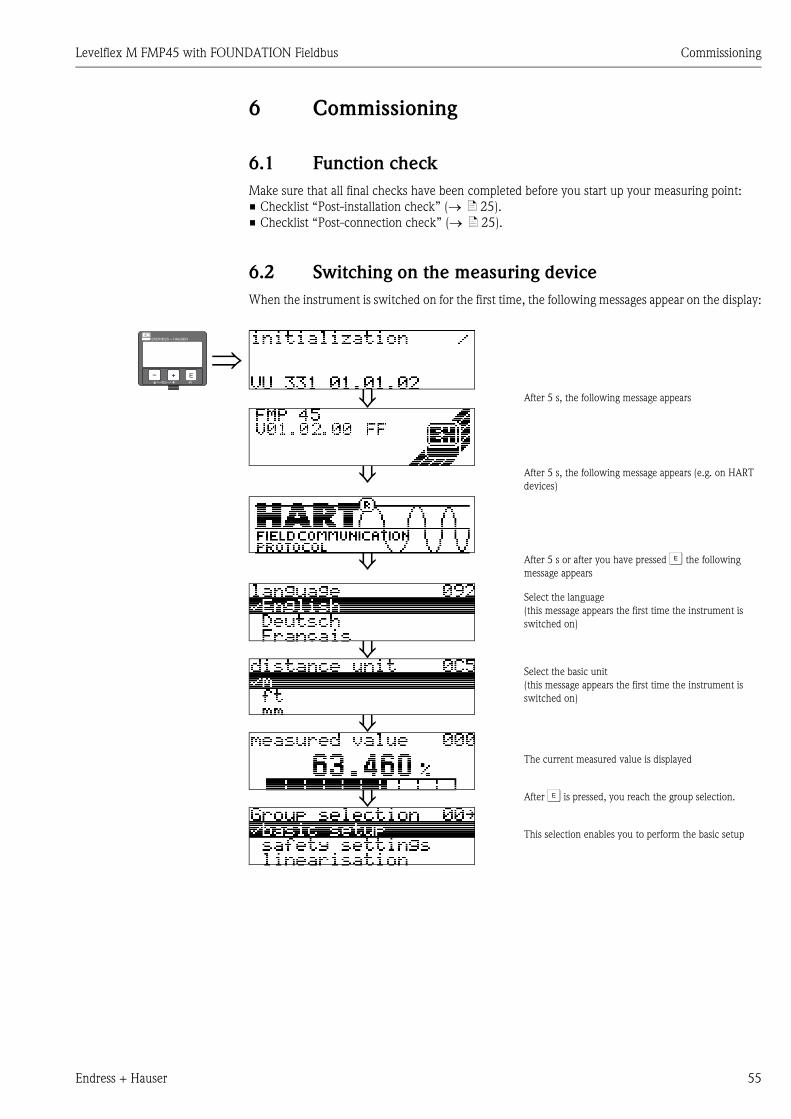
Levelflex M FMP45 with FOUNDATION Fieldbus Commissioning
Endress + Hauser 55
6 Commissioning
6.1 Function check
Make sure that all final checks have been completed before you start up your measuring point:
• Checklist “Post-installation check” (→ ä 25).
• Checklist “Post-connection check” (→ ä 25).
6.2 Switching on the measuring device
When the instrument is switched on for the first time, the following messages appear on the display:
⇒⇓ After 5 s, the following message appears
⇓ After 5 s, the following message appears (e.g. on HART
devices)
⇓ After 5 s or after you have pressed F the following
message appears
Select the language
(this message appears the first time the instrument is
switched on)
⇓Select the basic unit
(this message appears the first time the instrument is
switched on)
⇓The current measured value is displayed
⇓ After F is pressed, you reach the group selection.
This selection enables you to perform the basic setup
ENDRESS + HAUSER
E+–

Commissioning Levelflex M FMP45 with FOUNDATION Fieldbus
56 Endress + Hauser
6.3 Basic Setup
L00-FMP41Cxx-19-00-00-en-001
SD
UB
F
L
D
E
LN
LB
flange:referencepointofmeasurement
����������
��������
��������������
'�����
��������������
��������
�������
���������������
�����������
����������� ����
���
�������� ����
�� ��� ����
(des
crip
tion
see
BA
245
F)
basi
c se
tup
(sta
ndar
d)op
tion
E = empty calibr. (= zero) LN = probe lengthsetting in 005 setting in 033
F = full calibr. (= span) UB = upper blocking distancesetting in 006 setting in 059
D = distance (distance flange / product) SD = safety distancedisplay in 0A5 setting in 015
L = level LB = lower blockingdisplay in 0A6 distance
Levelflex M FMP45 with FOUNDATION Fieldbus Commissioning
Endress + Hauser 57
The basic setup is sufficient for successful commissioning in most applications.
The Levelflex is initially adjusted at the factory to the probe length ordered, so that in most cases
only the application parameters, that automatically adapt the device to the measuring conditions,
need to be entered. For models with current output, the factory adjustment for zero point and span
is F 4 mA and 20 mA, for digital outputs and the display module 0 % and 100 %.A linearisation
function with max. 32 points, that is based on a manually or semi-automatically input table, can be
activated on-site or via remote operation. This function enables, for example, the conversion of the
level into units of volume or weight.
! Note!
The Levelflex M allows to check for broken probe. On delivery, this function is switched off,
because otherwise shortening of the probe would be mistaken for a broken probe.
In order to activate this function, perform the following steps:
1. With the probe uncovered, perform a mapping ("range of mapping" (052) and "start
mapping." (053)).
2. Activate the "broken probe det" (019) function in the "safety settings" (01) function
group.
Complex measuring operations necessitate additional functions that the user can use to customise
the Levelflex as necessary to suit his specific requirements. The functions available to do this are
described in detail in the BA245F – "Description of the instrument functions" on the enclosed CD-
ROM.
Comply with the following instructions when configuring the functions in the "basic setup" (00):
• Select the functions as described on → ä 31.
• Certain functions (e.g. starting an interference echo mapping (053)) prompt you to confirm your
data entries. Press O or S to select "YES" and press F to confirm. The function is now started.
• If you do not press a key during a configurable time period (→ function group "display (09)") ,
an automatic return is made to the home position (measured value display).
! Note!
• The instrument continues to measure while data entry is in progress, i.e. the current measured
values are output via the signal outputs in the normal way.
• If the envelope curve mode is active on the display, the measured values are updated in a slower
cycle time. Thus, it is advisable to leave the envelope curve mode after the measuring point has
been optimised.
• If the power supply fails, all preset and parameterised values remain safely stored in the EEPROM.
" Caution!
All functions are described in detail, as is the overview of the operating menu itself, in the manual
BA245F – "Description of the instrument functions" on the enclosed CD-ROM.
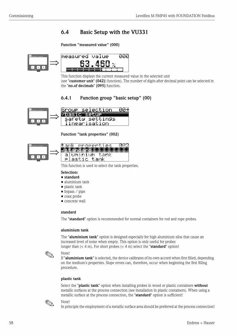
Commissioning Levelflex M FMP45 with FOUNDATION Fieldbus
58 Endress + Hauser
6.4 Basic Setup with the VU331
Function "measured value" (000)
This function displays the current measured value in the selected unit
(see "customer unit" (042)) function). The number of digits after decimal point can be selected in
the "no.of decimals" (095) function.
6.4.1 Function group "basic setup" (00)
Function "tank properties" (002)
This function is used to select the tank properties.
Selection:
• standard
• aluminium tank
• plastic tank
• bypass / pipe
• coax probe
• concrete wall
standard
The "standard" option is recommended for normal containers for rod and rope probes.
aluminium tank
The "aluminium tank" option is designed especially for high aluminium silos that cause an
increased level of noise when empty. This option is only useful for probes
longer than (< 4 m). For short probes (< 4 m) select the "standard" option!
! Note!
If "aluminium tank" is selected, the device calibrates of its own accord when first filled, depending
on the medium's properties. Slope errors can, therefore, occur when beginning the first filling
procedure.
plastic tank
Select the "plastic tank" option when installing probes in wood or plastic containers without
metallic surfaces at the process connection (see installation in plastic containers). When using a
metallic surface at the process connection, the "standard" option is sufficient!
! Note!
In principle the employment of a metallic surface area should be preferred at the process connection!
⇒ENDRESS + HAUSER
E+–
⇒ENDRESS + HAUSER
E+–
⇒ENDRESS + HAUSER
E+–

Levelflex M FMP45 with FOUNDATION Fieldbus Commissioning
Endress + Hauser 59
bypass / pipe
The "bypass / pipe" option is designed especially for the installation of probes in a bypass or a
stilling well. If this option is selected, the upper blocking distance is preset to 100 mm.
coax probe
Select the "coax probe" option when using a coaxial probe. When this setting is made, the
evaluation is adapted to the high sensitivity of the coax probe. This option should, therefore, not be
selected when using rope or rod probes.
concrete wall
The "concrete wall" option takes into account the signal-damping property of concrete walls when
mounting with < 1 m distance to the wall.
Function "medium property" (003)
This function is used to select the dielectric constant.
Selection:
• unknown
• 1.4 ... 1.6 (1,4 for installation in metallic pipes)
• 1.6 ... 1.9
• 1.9 ... 2.5
• 2.5 ... 4.0
• 4.0 ... 7.0
• > 7.0
The lower group applies to very loose or loosened bulk solids. Reduction of the max. possible
measuring range by means of:
• extremely loose surfaces of bulk solids, e.g. bulk solids with low piled density when filled
pneumatically.
• Build-up, primarily of moist products.
! Note!
Due to the high diffusion rate of ammonia it is recommended to use the FMP45 with gas-tight
bushing for measurements in this medium.
⇒ENDRESS + HAUSER
E+–
Media group DC (εr) Typical liquids Typ. measuring range
1 1.4...1.6 – Condensed gases, e.g. N2, CO2 4 m (157"), when installed in metallic pipes
2 1.6...1.9
– Liquefied gas, e.g. Propane
– Solvent
– Frigen / Freon
– Palm oil
9 m (354")
3 1.9...2.5 – Mineral oils, fuels 12 m (472")
4 2.5...4
– Benzene, styrene, toluene
– Furan
– Naphthalene
16 m (629")
5 4...7
– Chlorobenzene, chloroform
– Cellulose spray
– Isocyanate, aniline
25 m (984")
6 > 7
– Aqueous solutions
– Alcohols
– Acids, alkalis
30 m (1181")
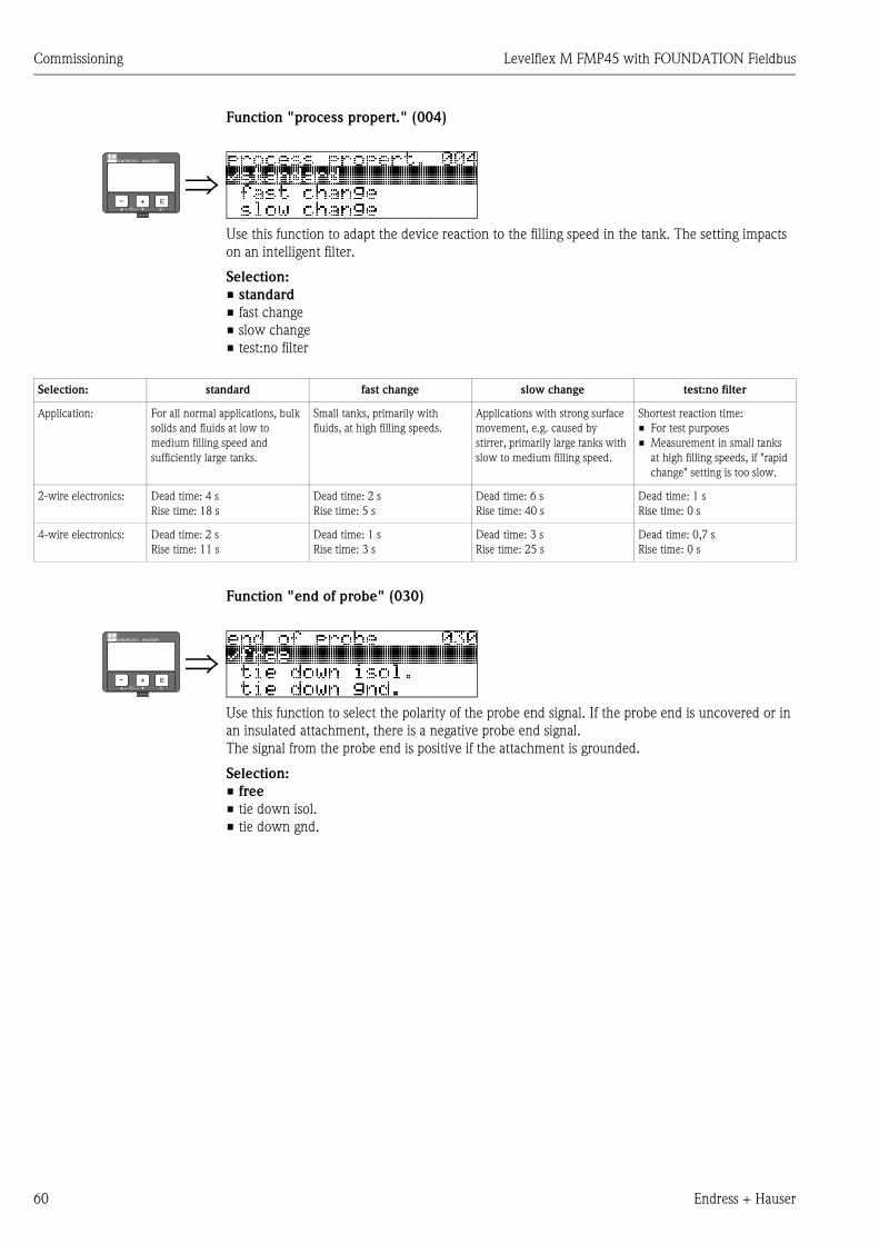
Commissioning Levelflex M FMP45 with FOUNDATION Fieldbus
60 Endress + Hauser
Function "process propert." (004)
Use this function to adapt the device reaction to the filling speed in the tank. The setting impacts
on an intelligent filter.
Selection:
• standard
• fast change
• slow change
• test:no filter
Function "end of probe" (030)
Use this function to select the polarity of the probe end signal. If the probe end is uncovered or in
an insulated attachment, there is a negative probe end signal.
The signal from the probe end is positive if the attachment is grounded.
Selection:
• free
• tie down isol.
• tie down gnd.
⇒ENDRESS + HAUSER
E+–
Selection: standard fast change slow change test:no filter
Application: For all normal applications, bulk
solids and fluids at low to
medium filling speed and
sufficiently large tanks.
Small tanks, primarily with
fluids, at high filling speeds.
Applications with strong surface
movement, e.g. caused by
stirrer, primarily large tanks with
slow to medium filling speed.
Shortest reaction time:
• For test purposes
• Measurement in small tanks
at high filling speeds, if "rapid
change" setting is too slow.
2-wire electronics: Dead time: 4 s
Rise time: 18 s
Dead time: 2 s
Rise time: 5 s
Dead time: 6 s
Rise time: 40 s
Dead time: 1 s
Rise time: 0 s
4-wire electronics: Dead time: 2 s
Rise time: 11 s
Dead time: 1 s
Rise time: 3 s
Dead time: 3 s
Rise time: 25 s
Dead time: 0,7 s
Rise time: 0 s
⇒ENDRESS + HAUSER
E+–
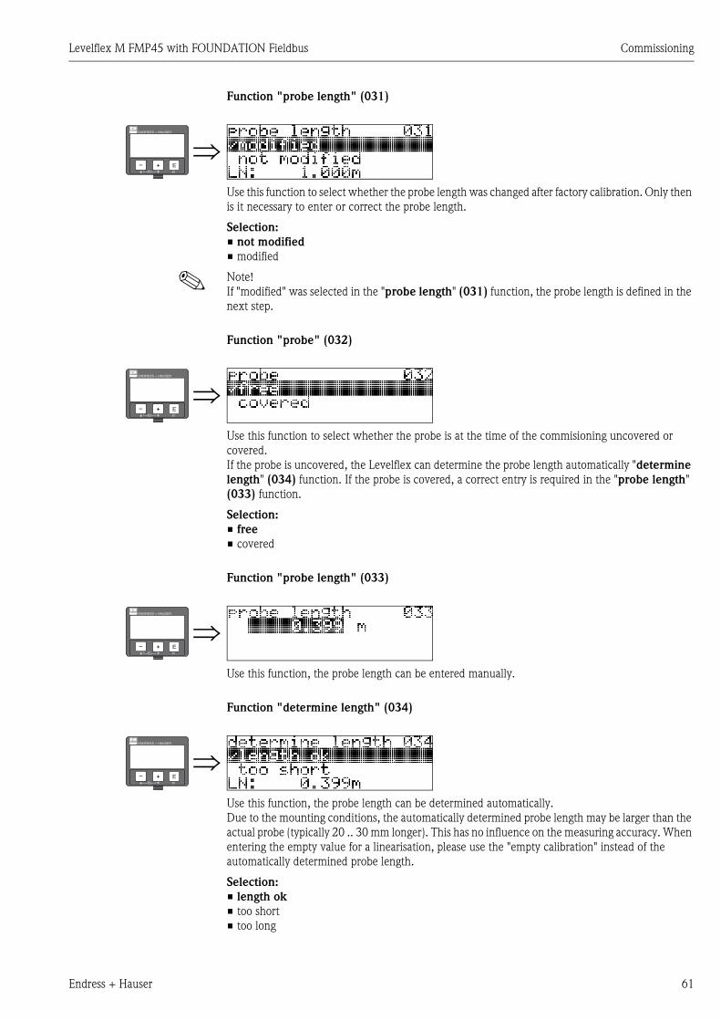
Levelflex M FMP45 with FOUNDATION Fieldbus Commissioning
Endress + Hauser 61
Function "probe length" (031)
Use this function to select whether the probe length was changed after factory calibration. Only then
is it necessary to enter or correct the probe length.
Selection:
• not modified
• modified
! Note!
If "modified" was selected in the "probe length" (031) function, the probe length is defined in the
next step.
Function "probe" (032)
Use this function to select whether the probe is at the time of the commisioning uncovered or
covered.
If the probe is uncovered, the Levelflex can determine the probe length automatically "determine
length" (034) function. If the probe is covered, a correct entry is required in the "probe length"
(033) function.
Selection:
• free
• covered
Function "probe length" (033)
Use this function, the probe length can be entered manually.
Function "determine length" (034)
Use this function, the probe length can be determined automatically.
Due to the mounting conditions, the automatically determined probe length may be larger than the
actual probe (typically 20 .. 30 mm longer). This has no influence on the measuring accuracy. When
entering the empty value for a linearisation, please use the "empty calibration" instead of the
automatically determined probe length.
Selection:
• length ok
• too short
• too long
⇒ENDRESS + HAUSER
E+–
⇒ENDRESS + HAUSER
E+–
⇒ENDRESS + HAUSER
E+–
⇒ENDRESS + HAUSER
E+–
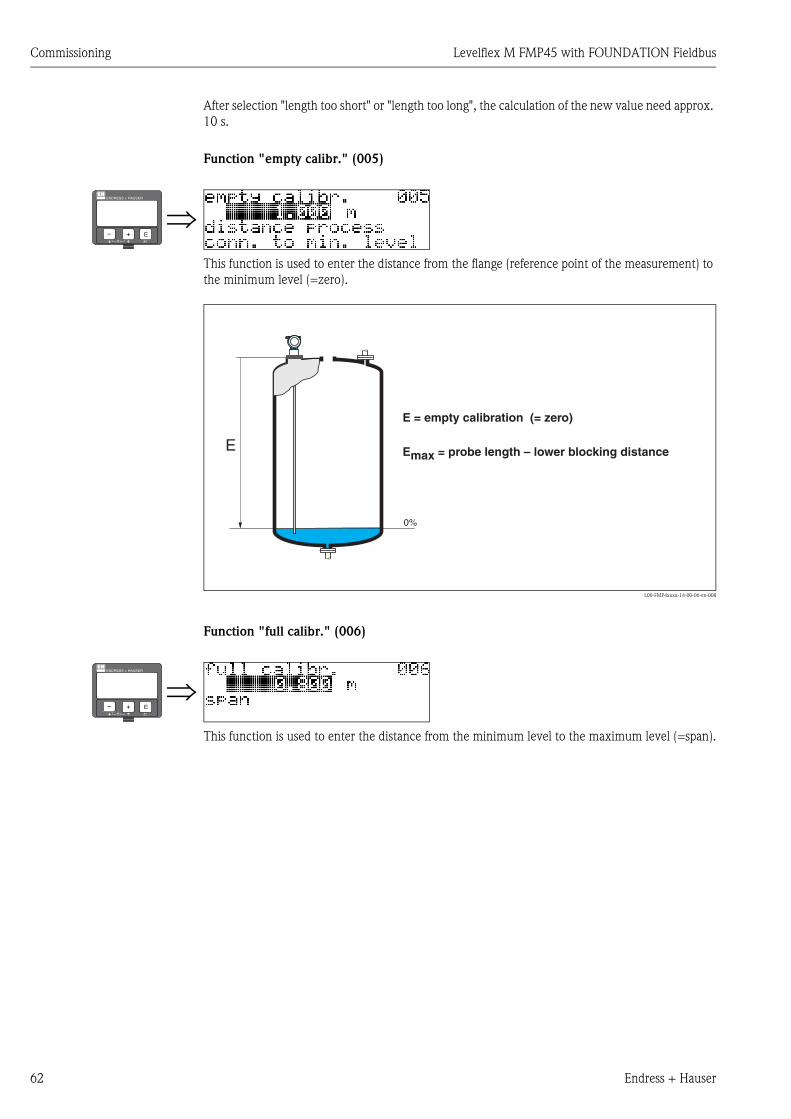
Commissioning Levelflex M FMP45 with FOUNDATION Fieldbus
62 Endress + Hauser
After selection "length too short" or "length too long", the calculation of the new value need approx.
10 s.
Function "empty calibr." (005)
This function is used to enter the distance from the flange (reference point of the measurement) to
the minimum level (=zero).
L00-FMP4xxxx-14-00-06-en-008
Function "full calibr." (006)
This function is used to enter the distance from the minimum level to the maximum level (=span).
⇒ENDRESS + HAUSER
E+–
0%
E
E = empty calibration (= zero)
Emax = probe length – lower blocking distance
⇒ENDRESS + HAUSER
E+–

Levelflex M FMP45 with FOUNDATION Fieldbus Commissioning
Endress + Hauser 63
L00-FMP4xxxx-14-00-06-en-009
! Note!
The usable measuring range lies between the lower and the upper blocking distance. The values for
empty distance (E) and span (F) can be set independently of this.
Display (008)
The distance measured from the reference point to the product surface and the meas. value
calculated with the aid of the empty adjustment are displayed. Check whether the values
correspond to the actual meas. value or the actual distance. The following cases can occur:
• Distance correct – meas. value correct -> continue with the next function
"check distance" (051).
• Distance correct – meas. value incorrect -> Check "empty calibr." (005)
• Distance incorrect – meas. value incorrect -> continue with the next function
"check distance" (051).
Function "check distance" (051)
This function triggers the mapping of interference echoes. To do so, the measured distance must be
compared with the actual distance to the product surface. The following options are available for
selection:
Selection:
• distance = ok
• dist. too small
• dist. too big
• dist. unknown
• manual
• probe free
100%
0%
F
F = full calibration (= span)
Fmax = E – upper blocking distance
⇒ENDRESS + HAUSER
E+–
⇒ENDRESS + HAUSER
E+–
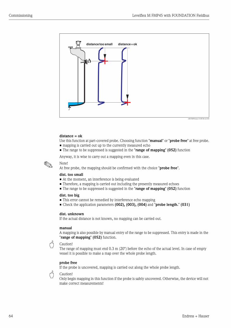
Commissioning Levelflex M FMP45 with FOUNDATION Fieldbus
64 Endress + Hauser
L00-FMP4xxxx-14-00-06-en-010
distance = ok
Use this function at part-covered probe. Choosing function "manual" or "probe free" at free probe.
• mapping is carried out up to the currently measured echo
• The range to be suppressed is suggested in the "range of mapping" (052) function
Anyway, it is wise to carry out a mapping even in this case.
! Note!
At free probe, the mapping should be confirmed with the choice "probe free".
dist. too small
• At the moment, an interference is being evaluated
• Therefore, a mapping is carried out including the presently measured echoes
• The range to be suppressed is suggested in the "range of mapping" (052) function
dist. too big
• This error cannot be remedied by interference echo mapping
• Check the application parameters (002), (003), (004) and "probe length." (031)
dist. unknown
If the actual distance is not known, no mapping can be carried out.
manual
A mapping is also possible by manual entry of the range to be suppressed. This entry is made in the
"range of mapping" (052) function.
" Caution!
The range of mapping must end 0.3 m (20") before the echo of the actual level. In case of empty
vessel it is possible to make a map over the whole probe length.
probe free
If the probe is uncovered, mapping is carried out along the whole probe length.
" Caution!
Only begin mapping in this function if the probe is safely uncovered. Otherwise, the device will not
make correct measurements!
+
+
distance toosmall distance =ok

Levelflex M FMP45 with FOUNDATION Fieldbus Commissioning
Endress + Hauser 65
Function "range of mapping" (052)
This function displays the suggested range of mapping. The reference point is always the reference
point of the measurement (→ ä 56). This value can be edited by the operator.
For manual mapping, the default value is 0,3 m.
Function "start mapping" (053)
This function is used to start the interference echo mapping up to the distance given in "range of
mapping" (052).
Selection:
• off: no mapping is carried out
• on: mapping is started
Display (008)
The distance measured from the reference point to the product surface and the meas. value
calculated with the aid of the empty alignment are displayed again. Check whether the values
correspond to the actual meas. value or the actual distance. The following cases can occur:
• Distance correct – meas. value correct -> basic setup completed
• Distance incorrect – meas. value incorrect -> a further interference echo mapping must be
carried out "check distance" (051).
• Distance correct – meas. value incorrect -> check "empty calibr" (005)
! Note!
After the basic setup, an evaluation of the measurement with the aid of the envelope curve
("envelope curve" (0E) function group) is recommended (→ ä 75).
⇒ENDRESS + HAUSER
E+–
⇒ENDRESS + HAUSER
E+–
⇒ENDRESS + HAUSER
E+–
⇒⇓ After 3 s, the following message appears
ENDRESS + HAUSER
E+–
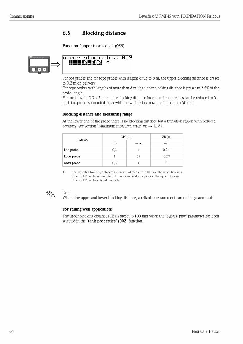
Commissioning Levelflex M FMP45 with FOUNDATION Fieldbus
66 Endress + Hauser
6.5 Blocking distance
Function "upper block. dist" (059)
For rod probes and for rope probes with lengths of up to 8 m, the upper blocking distance is preset
to 0.2 m on delivery.
For rope probes with lengths of more than 8 m, the upper blocking distance is preset to 2.5% of the
probe length.
For media with DC > 7, the upper blocking distance for rod and rope probes can be reduced to 0.1
m, if the probe is mounted flush with the wall or in a nozzle of maximum 50 mm.
Blocking distance and measuring range
At the lower end of the probe there is no blocking distance but a transition region with reduced
accuracy, see section "Maximum measured error" on → ä 67.
! Note!
Within the upper and lower blocking distance, a reliable measurement can not be guaranteed.
For stilling well applications
The upper blocking distance (UB) is preset to 100 mm when the "bypass/pipe" parameter has been
selected in the "tank properties" (002) function.
⇒ENDRESS + HAUSER
E+–
FMP45LN [m] UB [m]
min max min
Rod probe 0,3 4 0,2 1)
1) The indicated blocking distances are preset. At media with DC > 7, the upper blocking
distance UB can be reduced to 0.1 mm for rod and rope probes. The upper blocking
distance UB can be entered manually.
Rope probe 1 35 0,22)
Coax probe 0,3 4 0

Levelflex M FMP45 with FOUNDATION Fieldbus Commissioning
Endress + Hauser 67
Maximum measured error
Typical statements for reference conditions:
DIN EN 61298-2, percentage of the span.
If the reference conditions are not met, the offset/zero arising from the mounting situation may be
up to ±12 mm. This additional offset/zero can be compensated for by entering a correction
(function "offset" (057)) during commissioning.
Differing from this , the following measuring error is present in the vicinity of the probe end:
! Note!
Please reenter the blocking distance in the function group "extended calibr." (05) function
"upper block.dist" (059) when installing the device in a high nozzle: upper blocking distance (UB)
= nozzle height (H) + 50 mm.
L00-FMP4xxxx-14-00-06-xx-001
Output: digital analogue
sum of non-linearity,
non-repeatability
and hysteresis
measurig range:
– up to 10 m: ±3 mm
– > 10 m: ± 0.03 %
for PA coated rope
measuring range:
– up to 5 m: ±5 mm
– > 5 m: ± 0.1 %
± 0.06 %
Offset / Zero ±4 mm ± 0.03 %
L00-FMP4xxxx-05-00-00-en-001 L00-FMP4xxxx-05-00-00-en-002
rod probe and coax probe
-80
-60
-40
-20
0
20
40
60
80
0 50 100 150 200 250 300
distance from probe end [mm]
su
m o
f n
on
-lin
eari
ty, n
on
-rep
eata
bilit
y
an
d h
yste
resis
[m
m]
DC = 2
DC > 7
rope probe
-80
-60
-40
-20
0
20
40
60
80
0 50 100 150 200 250 300
distance from probe end [mm]
su
m o
f n
on
-lin
eari
ty, n
on
-rep
eata
bilit
y
an
d h
ys
tere
sis
[m
m] DC > 7
UBH
50
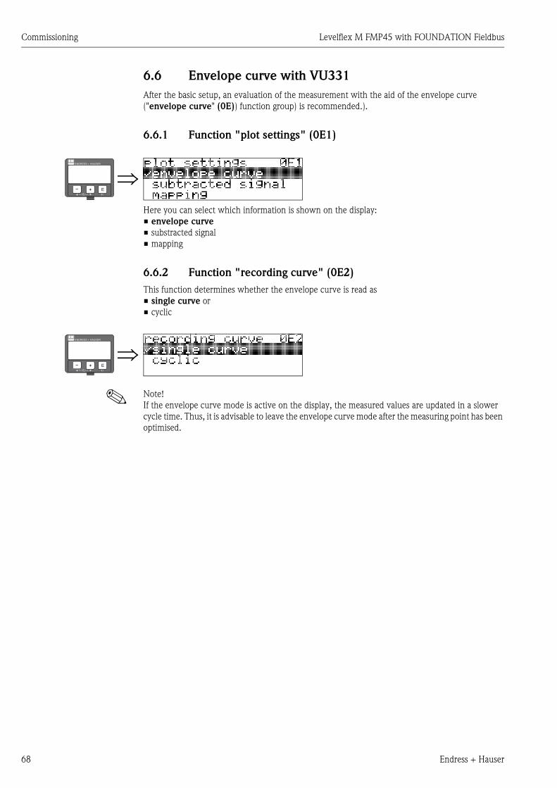
Commissioning Levelflex M FMP45 with FOUNDATION Fieldbus
68 Endress + Hauser
6.6 Envelope curve with VU331
After the basic setup, an evaluation of the measurement with the aid of the envelope curve
("envelope curve" (0E)) function group) is recommended.).
6.6.1 Function "plot settings" (0E1)
Here you can select which information is shown on the display:
• envelope curve
• substracted signal
• mapping
6.6.2 Function "recording curve" (0E2)
This function determines whether the envelope curve is read as
• single curve or
• cyclic
! Note!
If the envelope curve mode is active on the display, the measured values are updated in a slower
cycle time. Thus, it is advisable to leave the envelope curve mode after the measuring point has been
optimised.
⇒ENDRESS + HAUSER
E+–
⇒ENDRESS + HAUSER
E+–
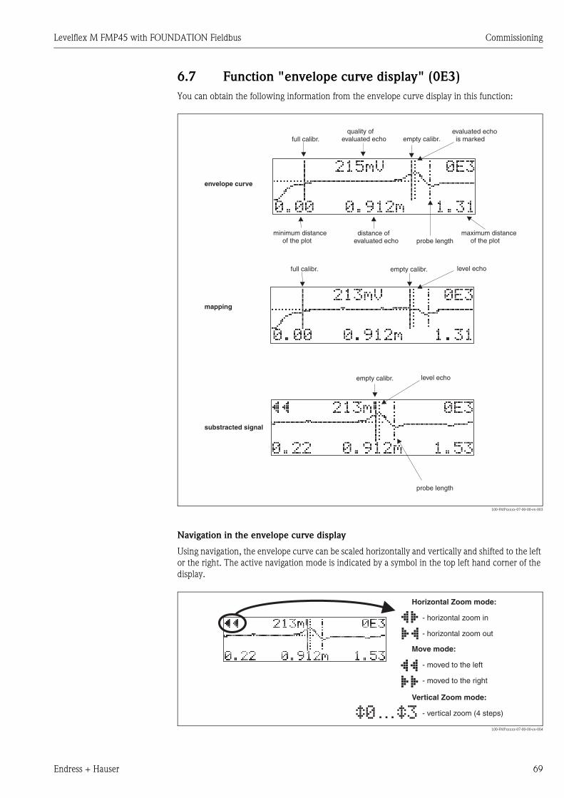
Levelflex M FMP45 with FOUNDATION Fieldbus Commissioning
Endress + Hauser 69
6.7 Function "envelope curve display" (0E3)
You can obtain the following information from the envelope curve display in this function:
L00-FMPxxxxx-07-00-00-en-003
Navigation in the envelope curve display
Using navigation, the envelope curve can be scaled horizontally and vertically and shifted to the left
or the right. The active navigation mode is indicated by a symbol in the top left hand corner of the
display.
L00-FMPxxxxx-07-00-00-en-004
minimum distanceof the plot
maximum distanceof the plot
distance ofevaluated echo
evaluated echois marked
quality ofevaluated echo empty calibr.
empty calibr.
empty calibr.
envelope curve
substracted signal
mapping
level echo
level echo
full calibr.
full calibr.
probe length
probe length
…
Move mode:
- m
-
oved to the left
moved to the right
Horizontal Zoom mode:
- h
-
orizontal zoom in
horizontal zoom out
Vertical Zoom mode:
- vertical zoom (4 steps)
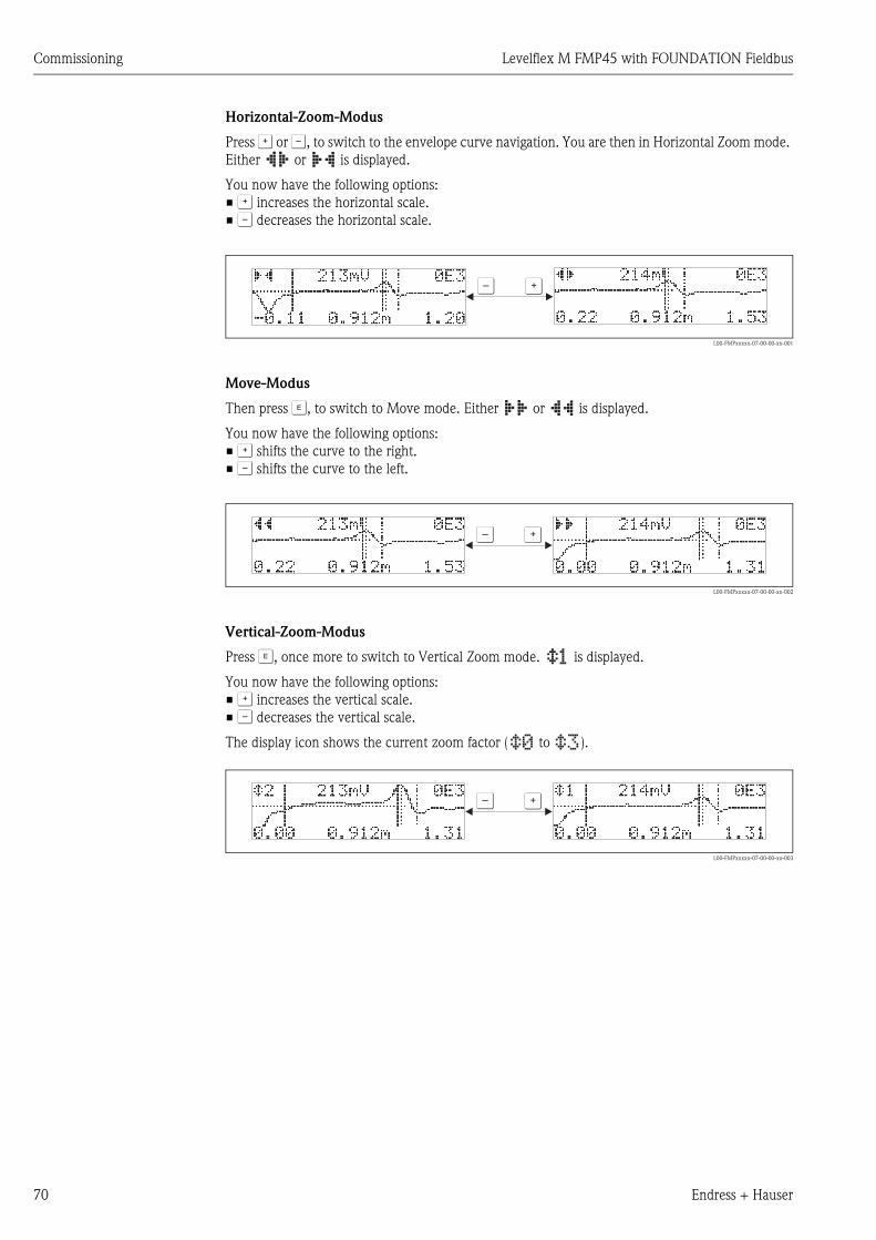
Commissioning Levelflex M FMP45 with FOUNDATION Fieldbus
70 Endress + Hauser
Horizontal-Zoom-Modus
Press O or S, to switch to the envelope curve navigation. You are then in Horizontal Zoom mode.
Either or is displayed.
You now have the following options:
• O increases the horizontal scale.
• S decreases the horizontal scale.
L00-FMPxxxxx-07-00-00-xx-001
Move-Modus
Then press F, to switch to Move mode. Either or is displayed.
You now have the following options:
• O shifts the curve to the right.
• S shifts the curve to the left.
L00-FMPxxxxx-07-00-00-xx-002
Vertical-Zoom-Modus
Press F, once more to switch to Vertical Zoom mode. is displayed.
You now have the following options:
• O increases the vertical scale.
• S decreases the vertical scale.
The display icon shows the current zoom factor ( to ).
L00-FMPxxxxx-07-00-00-xx-003
OS
OS
OS
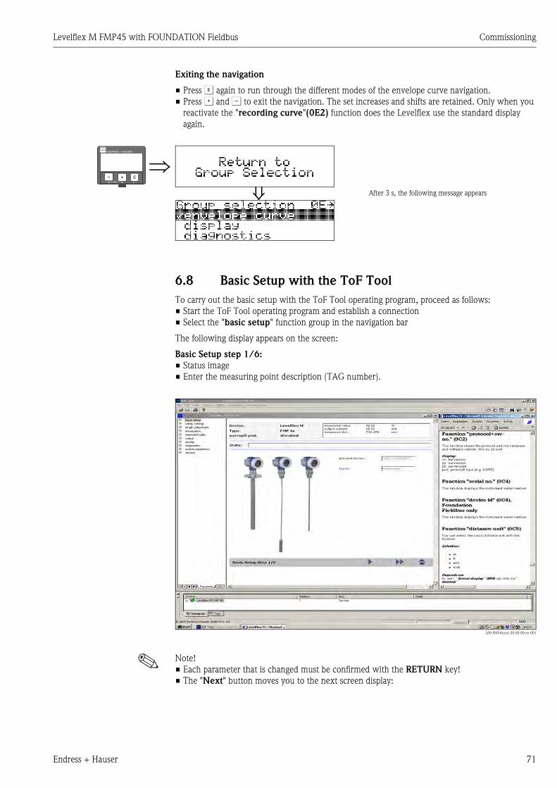
Levelflex M FMP45 with FOUNDATION Fieldbus Commissioning
Endress + Hauser 71
Exiting the navigation
• Press F again to run through the different modes of the envelope curve navigation.
• Press O and S to exit the navigation. The set increases and shifts are retained. Only when you
reactivate the "recording curve"(0E2) function does the Levelflex use the standard display
again.
6.8 Basic Setup with the ToF Tool
To carry out the basic setup with the ToF Tool operating program, proceed as follows:
• Start the ToF Tool operating program and establish a connection
• Select the "basic setup" function group in the navigation bar
The following display appears on the screen:
Basic Setup step 1/6:
• Status image
• Enter the measuring point description (TAG number).
L00-FMP4xxxx-20-00-00-en-001
! Note!
• Each parameter that is changed must be confirmed with the RETURN key!
• The "Next" button moves you to the next screen display:
⇒⇓ After 3 s, the following message appears
ENDRESS + HAUSER
E+–
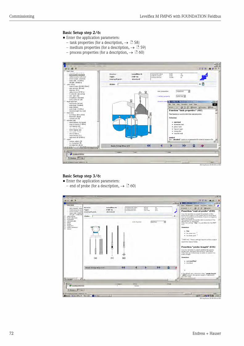
Commissioning Levelflex M FMP45 with FOUNDATION Fieldbus
72 Endress + Hauser
Basic Setup step 2/6:
• Enter the application parameters:
– tank properties (for a description, → ä 58)
– medium properties (for a description, → ä 59)
– process properties (for a description, → ä 60)
l00-fmp4xxxx-20-00-00-en-002
Basic Setup step 3/6:
• Enter the application parameters:
– end of probe (for a description, → ä 60)
l00-fmp4xxxx-20-00-00-en-003
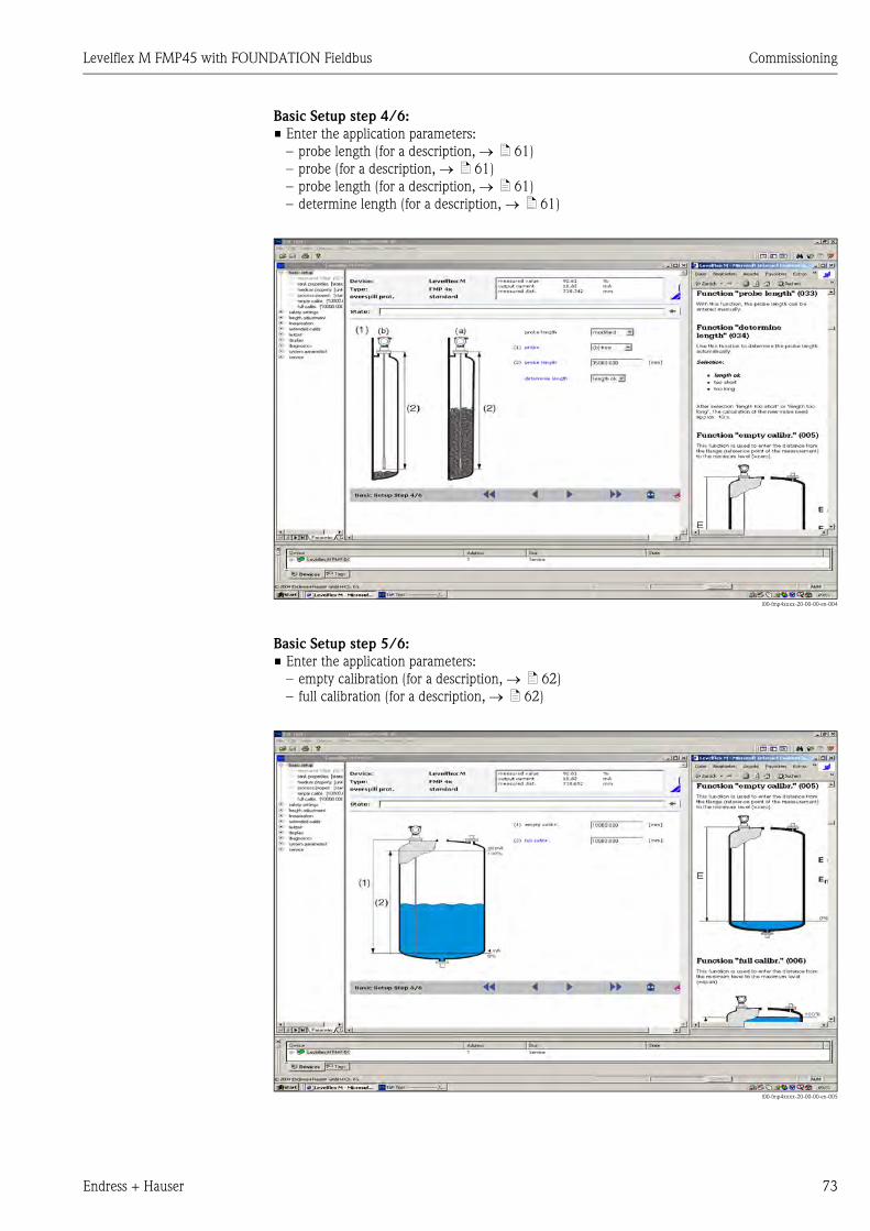
Levelflex M FMP45 with FOUNDATION Fieldbus Commissioning
Endress + Hauser 73
Basic Setup step 4/6:
• Enter the application parameters:
– probe length (for a description, → ä 61)
– probe (for a description, → ä 61)
– probe length (for a description, → ä 61)
– determine length (for a description, → ä 61)
l00-fmp4xxxx-20-00-00-en-004
Basic Setup step 5/6:
• Enter the application parameters:
– empty calibration (for a description, → ä 62)
– full calibration (for a description, → ä 62)
l00-fmp4xxxx-20-00-00-en-005
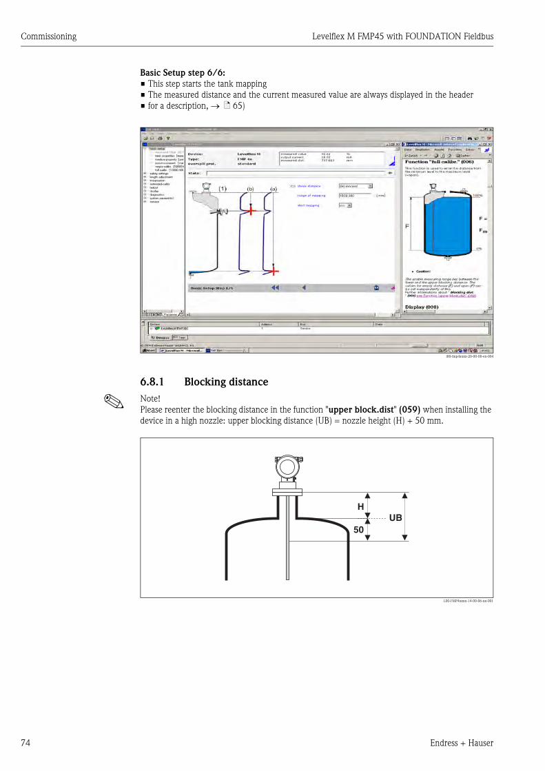
Commissioning Levelflex M FMP45 with FOUNDATION Fieldbus
74 Endress + Hauser
Basic Setup step 6/6:
• This step starts the tank mapping
• The measured distance and the current measured value are always displayed in the header
• for a description, → ä 65)
l00-fmp4xxxx-20-00-00-en-004
6.8.1 Blocking distance
! Note!
Please reenter the blocking distance in the function "upper block.dist" (059) when installing the
device in a high nozzle: upper blocking distance (UB) = nozzle height (H) + 50 mm.
L00-FMP4xxxx-14-00-06-xx-001
UBH
50
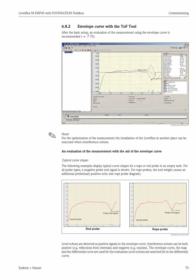
Levelflex M FMP45 with FOUNDATION Fieldbus Commissioning
Endress + Hauser 75
6.8.2 Envelope curve with the ToF Tool
After the basic setup, an evaluation of the measurement using the envelope curve is
recommended (→ ä 75).
L00-FMP4xxxx-20-00-00-en-007
! Note!
For the optimization of the measurement the installation of the Levelflex in another place can be
executed when enterference echoes.
An evaluation of the measurement with the aid of the envelope curve
Typical curve shape:
The following examples display typical curve shapes for a rope or rod probe in an empty tank. For
all probe types, a negative probe end signal is shown. For rope probes, the end weight causes an
additional preliminary positive echo (see rope probe diagram).
L00-FMP40xxx-05-00-00-en-024
Level echoes are detected as positive signals in the envelope curve. Interference echoes can be both
positive (e.g. reflections from internals) and negative (e.g. nozzles). The envelope curve, the map
and the differential curve are used for the evaluation.Level echoes are searched for in the differential
curve.
400.00 400.00
[mV] [mV]
300.00 300.00
200.00 200.00
100.00 100.00
0.00 0.00
-100.00 -100.00
-200.00 -200.00
-300.00 -300.00
-400.00 -400.00
-500.00 -500.00
0.00 0.000.20 0.200.40 0.400.60 0.600.80 0.801.00 1.00 1.20 1.40[m] [m]
LN LNE EF F
(1.00 m, -143.00 mV)(1.08 m, -115.00 mV)
Rod probe Rope probe
Probe end signal
Launch pulse
Probe end signal
Launch pulse
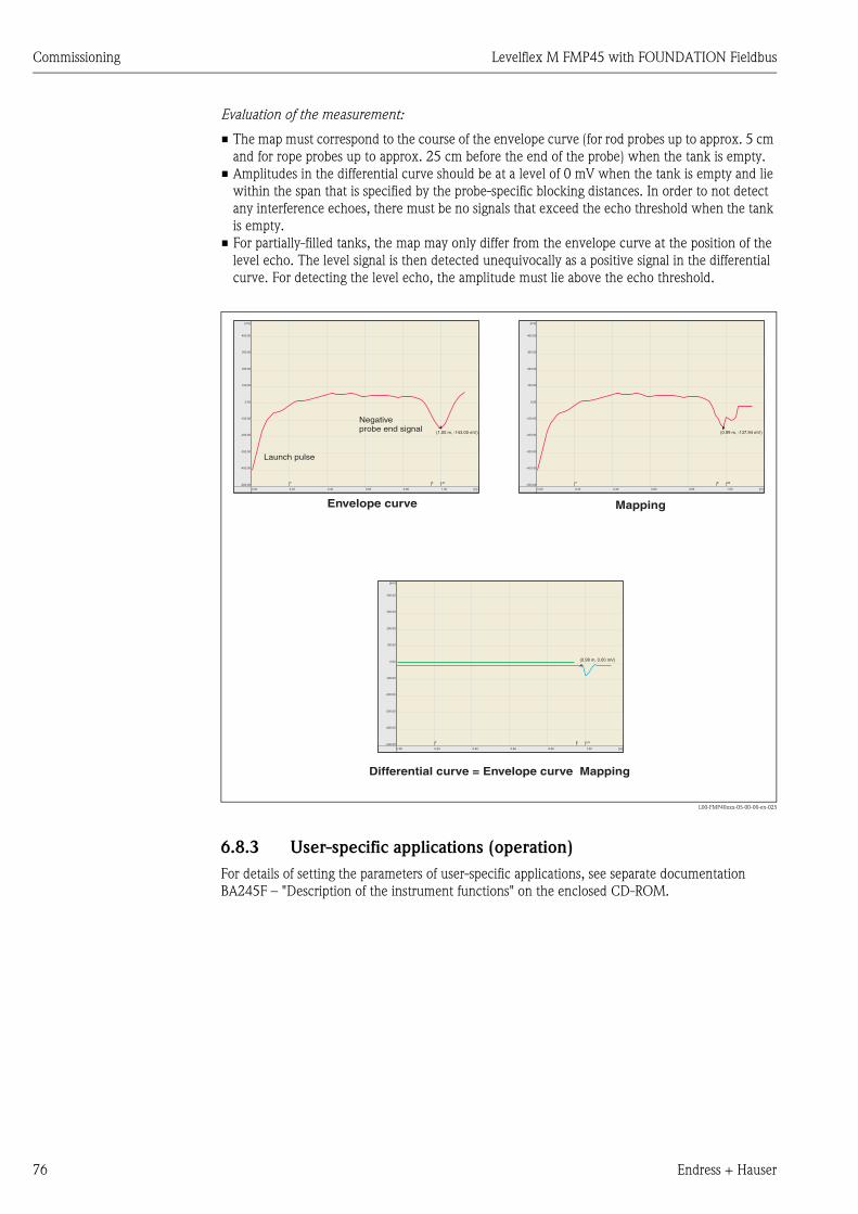
Commissioning Levelflex M FMP45 with FOUNDATION Fieldbus
76 Endress + Hauser
Evaluation of the measurement:
• The map must correspond to the course of the envelope curve (for rod probes up to approx. 5 cm
and for rope probes up to approx. 25 cm before the end of the probe) when the tank is empty.
• Amplitudes in the differential curve should be at a level of 0 mV when the tank is empty and lie
within the span that is specified by the probe-specific blocking distances. In order to not detect
any interference echoes, there must be no signals that exceed the echo threshold when the tank
is empty.
• For partially-filled tanks, the map may only differ from the envelope curve at the position of the
level echo. The level signal is then detected unequivocally as a positive signal in the differential
curve. For detecting the level echo, the amplitude must lie above the echo threshold.
L00-FMP40xxx-05-00-00-en-025
6.8.3 User-specific applications (operation)
For details of setting the parameters of user-specific applications, see separate documentation
BA245F – "Description of the instrument functions" on the enclosed CD-ROM.
400.00
400.00
400.00
[mV]
[mV]
[mV]
300.00
300.00
300.00
200.00
200.00
200.00
100.00
100.00
100.00
0.00
0.00
0.00
-100.00
-100.00
-100.00
-200.00
-200.00
-200.00
-300.00
-300.00
-300.00
-400.00
-400.00
-400.00
-500.00
-500.00
-500.00
0.00
0.00
0.000.20
0.20
0.200.40
0.40
0.400.60
0.60
0.600.80
0.80
0.801.00
1.00
1.00[m]
[m]
[m]
LN
LN
LNE
E
EF
F
F
(1.00 m, -143.00 mV)
(0.98 m, 0.00 mV)
(0.99 m, -137.94 mV)
Launch pulse
Negativeprobe end signal
Envelope curve
Differential curve = Envelope curve Mapping
Mapping
Levelflex M FMP45 with FOUNDATION Fieldbus Maintenance
Endress + Hauser 77
7 Maintenance
The Levelflex M measuring instrument requires no special maintenance.
Exterior cleaning
When cleaning the Levelflex M , always use cleaning agents that do not attack the surface of the
housing and the seals.
Repairs
The Endress+Hauser repair concept assumes that the measuring devices have a modular design and
that customers are able to undertake repairs themselves. Spare parts are contained in suitable kits.
They contain the related replacement instructions. All the spare parts kits which you can order from
Endress+Hauser for repairs to the Levelflex M are listed with their order numbers on → ä 86 and
89. Please contact Endress+Hauser Service for further information on service and spare parts.
Repairs to Ex-approved devices
When carrying out repairs to Ex-approved devices, please note the following:
• Repairs to Ex-approved devices may only be carried out by trained personnel or by
Endress+Hauser Service.
• Comply with the prevailing standards, national Ex-area regulations, safety instructions (XA) and
certificates.
• Only use original spare parts from Endress+Hauser.
• When ordering a spare part, please note the device designation on the nameplate. Only replace
parts with identical parts.
• Carry out repairs according to the instructions. On completion of repairs, carry our the specified
routine test on the device.
• Only Endress+Hauser Service may convert a certified device into a different certified variant.
• Document all repair work and conversions.
Replacement
After a complete Levelflex M or electronic module has been replaced, the parameters can be
downloaded into the instrument again via the communication interface. Prerequisite to this is that
the data were uploaded to the PC beforehand using the ToF Tool.
Measurement can continue without having to carry out a new setup.
• You may have to activate linearisation (see BA245F – "Description of the instrument functions"
on the enclosed CD-ROM.)
• You may need to record the tank map again (see Basic Setup)
After an probe or electronic has been replaced, a new calibration must be carried out. This is
described in the repair instructions.
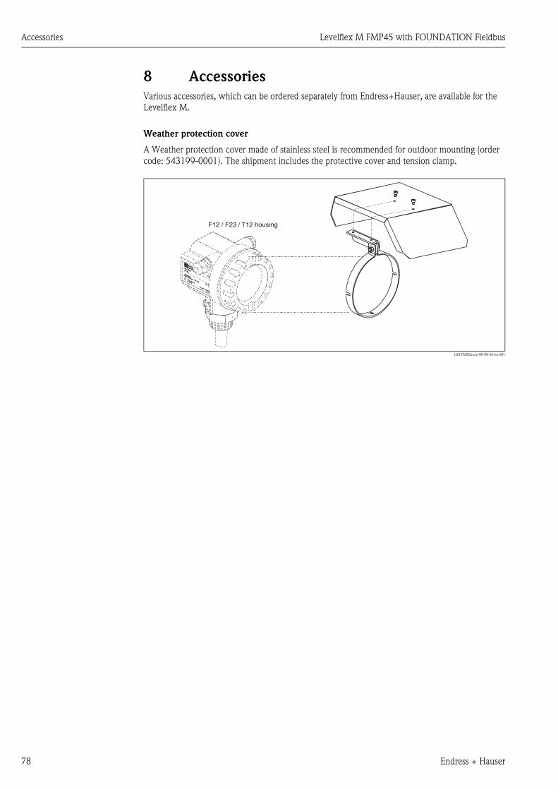
Accessories Levelflex M FMP45 with FOUNDATION Fieldbus
78 Endress + Hauser
8 Accessories
Various accessories, which can be ordered separately from Endress+Hauser, are available for the
Levelflex M.
Weather protection cover
A Weather protection cover made of stainless steel is recommended for outdoor mounting (order
code: 543199-0001). The shipment includes the protective cover and tension clamp.
L00-FMR2xxxx-00-00-06-en-001
ENDRESS+HAUSER
MICROPILOT II
ENDRESS+HAUSER
MICROPILOT II
IP 65
Order Code:Ser.-No.:
Order Code:Ser.-No.:
MessbereichMeasuring range
MessbereichMeasuring rangeU 16...36 V DC
4...20 mA
U 16...36 V DC4...20 mA
max. 20 m
max. 20 m
Made in
Germ
any
Maulb
urg
Made in
Germ
any
Maulb
urg
T>70°C :
A
t >85°C
T>70°C :
A
t >85°C
F12 / F23 / T12 housing
Levelflex M FMP45 with FOUNDATION Fieldbus Accessories
Endress + Hauser 79
Commubox FXA291
The Commubox FXA291 connects Endress+Hauser field instruments with CDI interface (=
Endress+Hauser Common Data Interface) to the USB interface of a personal computer or a
notebook. For details refer to TI405C/07/en.
! Note!
For the following Endress+Hauser instruments you need the "ToF Adapter FXA291" as an additional
accessory:
• Cerabar S PMC71, PMP7x
• Deltabar S PMD7x, FMD7x
• Deltapilot S FMB70
• Gammapilot M FMG60
• Levelflex M FMP4x
• Micropilot FMR130/FMR131
• Micropilot M FMR2xx
• Micropilot S FMR53x, FMR540
• Prosonic FMU860/861/862
• Prosonic M FMU4x
• Tank Side Monitor NRF590 (with additional adapter cable)
ToF Adapter FXA291
The ToF Adapter FXA291 connects the Commubox FXA291 via the USB interface of a personal
computer or a notebook to the following Endress+Hauser instruments:
• Cerabar S PMC71, PMP7x
• Deltabar S PMD7x, FMD7x
• Deltapilot S FMB70
• Gammapilot M FMG60
• Levelflex M FMP4x
• Micropilot FMR130/FMR131
• Micropilot M FMR2xx
• Micropilot S FMR53x, FMR540
• Prosonic FMU860/861/862
• Prosonic M FMU4x
• Tank Side Monitor NRF590 (with additional adapter cable)
For details refer to KA271F/00/a2.
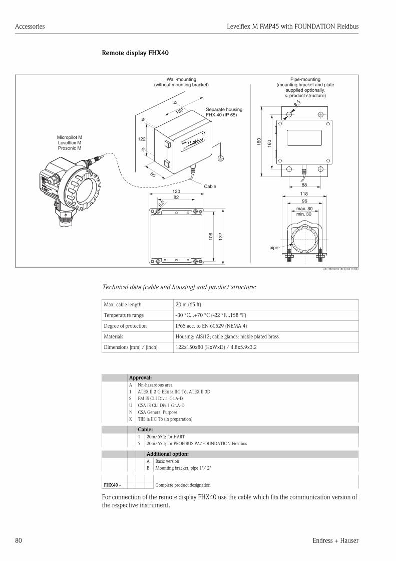
Accessories Levelflex M FMP45 with FOUNDATION Fieldbus
80 Endress + Hauser
Remote display FHX40
L00-FMxxxxxx-00-00-06-en-003
Technical data (cable and housing) and product structure:
For connection of the remote display FHX40 use the cable which fits the communication version of
the respective instrument.
ENDRESS+HAUSER
ENDRESS+HAUSER
IP 65IP 65
Order Code:Ser.-No.:
Order Code:Ser.-No.:
MessbereichMeasuring range
MessbereichMeasuring rangeU 16...36 V DC
4...20 mA
U 16...36 V DC4...20 mA
max. 20 m
max. 20 m
Made in
Germ
any
M
aulb
urg
Made in
Germ
any
M
aulb
urg
T>70°C :
A
t >85°C
T>70°C :
A
t >85°C 82
6,3
106
122
120
max. 80min. 30
96
88
160
8,5
118
180Micropilot M
Levelflex MProsonic M
Separate housingFHX 40 (IP 65)
Cable
122
150
80
Wall-mounting(without mounting bracket)
Pipe-mounting(mounting bracket and plate
supplied optionally,s. product structure)
pipe
Max. cable length 20 m (65 ft)
Temperature range -30 °C...+70 °C (-22 °F...158 °F)
Degree of protection IP65 acc. to EN 60529 (NEMA 4)
Materials Housing: AlSi12; cable glands: nickle plated brass
Dimensions [mm] / [inch] 122x150x80 (HxWxD) / 4.8x5.9x3.2
Approval:
A Nn-hazardous area
1 ATEX II 2 G EEx ia IIC T6, ATEX II 3D
S FM IS Cl.I Div.1 Gr.A-D
U CSA IS Cl.I Div.1 Gr.A-D
N CSA General Purpose
K TIIS ia IIC T6 (in preparation)
Cable:
1 20m/65ft; for HART
5 20m/65ft; for PROFIBUS PA/FOUNDATION Fieldbus
Additional option:
A Basic version
B Mounting bracket, pipe 1"/ 2"
FHX40 - Complete product designation

Levelflex M FMP45 with FOUNDATION Fieldbus Trouble-shooting
Endress + Hauser 81
9 Trouble-shooting
9.1 Trouble-shooting instructions
L00-FMP4xxxx-19-00-00-en-010
Instrument doesnot respond
Check voltage andcompare it with thespecifications on thenameplate.
Connect thecorrect voltage
Instrument works? Ready
Check the polarityof the voltage.
Check power connectionto electronic board
Correct the polarity
Connect plug
Instrument works?
Instrument works?
Ready
Ready
Values on displayinvissible
ok
ok
ok
Yes
Yes
Yes
No
No
No
No
Not ok
Not ok
Not ok
Check plug contactof the display.
Connect the plugcorrectly
Correct configuration
Display works? Ready
Ready
Yes
ok
No
Not ok
Yes
No
Levelflex M -Trouble Shooting
ok
Output current between3.6 …22mA ?
Contrast: F O+
The display is possibly defective.Contact Endress+Hauser Service
Yes
Output current< 3.6 mA ? (2 wire)< 2.4 mA ? (4 wire)
No
Check cablingCorrect thecabling
Current is ok? ReadyYes
No
Possibly defective electronicsContact Endress+Hauser Service
HARTcommunicationdoes notfunction
Is the communicationresistor installedaccording to theOM?
Install the fuse(see the OM)
Communication ok? Ready
Ready
ok
Yes
Yes
No
No
Connect theCommubox(see the OM)
Communication ok? Ready
Set the switchcorrectly
Communication ok Ready
Ready
Contact ServiceEndress+Hauser
Contact ServiceEndress+Hauser
Contact Endress+Hauser Service
ok
ok
ok
Yes
No
Yes
Yes
No
No
ok
Not ok
Not ok
Not ok
Not ok
Not ok
Not ok
?
Is the switch on theCommubox forselecting HARTin the correct position?
Is the Commuboxconnected accordingto the OM?
Communicationvia Service adapterdoes not function
Instrumentmeasuresincorrectly
Check configurationof COM port on PC
Check basic setup
Proceed accordingto section'Trouble shooting’ in OM
Repeatbasic setup
Not ok
Yes
Yes
Yes
Yes
Yes
CommunicationPA does notfunction
Check cabling +terminator
EMC interference?
ok
Correct cabling +terminator
Not ok
Check screening(see BA Section'Connection’)
Yes
Communication ok?
Communication ok?
Measurement ok?
ReadyYes
No
Communication ok? ReadyYes
No

Trouble-shooting Levelflex M FMP45 with FOUNDATION Fieldbus
82 Endress + Hauser
9.2 System error messages
Code Description Possible cause Remedy
A102 checksum error
general reset & new calibr.
required
device has been powered off before data
could be stored;
emc problem;
E2PROM defect
reset
avoid emc problem;
if alarm prevails after reset,
exchange electronics
W103 initialising - please wait E2PROM storage not yet finished wait some seconds; if warning
prevails, exchange electronics
A106 downloading please wait processing data download wait until warning disappears
A110 checksum error
general reset & new calibr.
required.
device has been powered off before data
could be stored;
emc problem;
E2PROM defect
reset
avoid emc problem;
if alarm prevails after reset,
exchange electronics
A111 electronics defect RAM defective reset
if alarm prevails after reset,
exchange electronics
A113 electronics defect ROM defective reset
if alarm prevails after reset,
exchange electronics
A114 electronics defect E2PROM defective reset
if alarm prevails after reset,
exchange electronics
A115 electronics defect general hardware problem Reset
if alarm prevails after reset,
exchange electronics
A116 download error
repeat download
checksum of stored data not correct restart download of data
A121 electronics defect no factory calibration existant; E2PROM
defective
contact service
W153 initialising - please wait initialisation of electronics wait some seconds; if warning
prevails, power off device and
power on again
A160 checksum error
general reset & new calibr.
required.
device has been powered off before data
could be stored;
emc problem;
E2PROM defect
reset
avoid emc problem;
if alarm prevails after reset,
exchange electronics
A164 electronics defect hardware problem reset
if alarm prevails after reset,
exchange electronics
A171 electronics defect hardware problem reset
if alarm prevails after reset,
exchange electronics
A221 Probe pulse deviation from
average values
HF module or cable between HF module
and electronics defective
Check contacts on HF module
If fault cannot be eliminated:
Replace HF module
A241 Broken probe Broken probe orvalue for probe length is
too short
Check the probe length in 033,
Check the probe itself,if the probe is
broken, change the probe, or
change to a non contact system
A251 Feedthrough Lost contact in the process feedthrough Replace process feedtrough
A261 HF cable defective HF cable defective or HF connector
removed
Check HF connector, replace cable
if defective
W275 Offset too high Temperature at the electronics too high or
HF module defective
Check temperature, replace HF
module if defective
W512 recording of mapping please
wait
mapping active wait some seconds until alarm
disappears
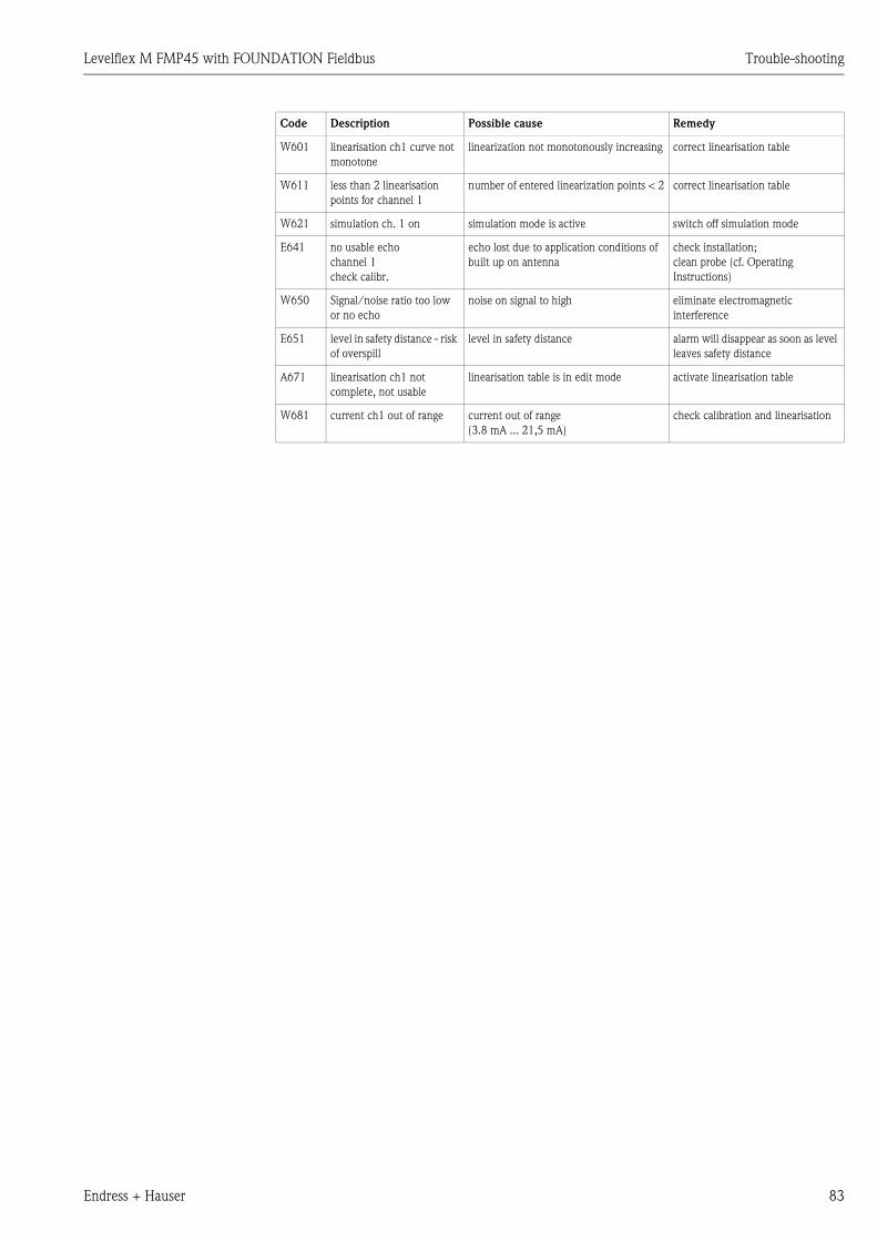
Levelflex M FMP45 with FOUNDATION Fieldbus Trouble-shooting
Endress + Hauser 83
W601 linearisation ch1 curve not
monotone
linearization not monotonously increasing correct linearisation table
W611 less than 2 linearisation
points for channel 1
number of entered linearization points < 2 correct linearisation table
W621 simulation ch. 1 on simulation mode is active switch off simulation mode
E641 no usable echo
channel 1
check calibr.
echo lost due to application conditions of
built up on antenna
check installation;
clean probe (cf. Operating
Instructions)
W650 Signal/noise ratio too low
or no echo
noise on signal to high eliminate electromagnetic
interference
E651 level in safety distance - risk
of overspill
level in safety distance alarm will disappear as soon as level
leaves safety distance
A671 linearisation ch1 not
complete, not usable
linearisation table is in edit mode activate linearisation table
W681 current ch1 out of range current out of range
(3.8 mA ... 21,5 mA)
check calibration and linearisation
Code Description Possible cause Remedy
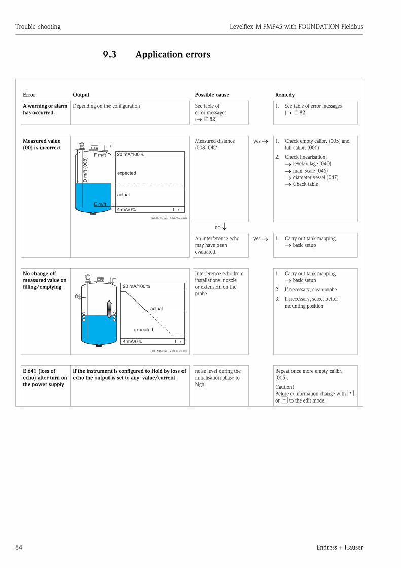
Trouble-shooting Levelflex M FMP45 with FOUNDATION Fieldbus
84 Endress + Hauser
9.3 Application errors
Error Output Possible cause Remedy
A warning or alarm
has occurred.
Depending on the configuration See table of
error messages
(→ ä 82)
1. See table of error messages
(→ ä 82)
Measured value
(00) is incorrect
L00-FMP4xxxx-19-00-00-en-019
Measured distance
(008) OK?
yes → 1. Check empty calibr. (005) and
full calibr. (006)
2. Check linearisation:
→ level/ullage (040)
→ max. scale (046)
→ diameter vessel (047)
→ Check table
no ↓An interference echo
may have been
evaluated.
yes → 1. Carry out tank mapping
→ basic setup
No change off
measured value on
filling/emptying
L00-FMR2xxxx-19-00-00-en-014
Interference echo from
installations, nozzle
or extension on the
probe
1. Carry out tank mapping
→ basic setup
2. If necessary, clean probe
3. If necessary, select better
mounting position
E 641 (loss of
echo) after turn on
the power supply
If the instrument is configured to Hold by loss of
echo the output is set to any value/current.
noise level during the
initialisation phase to
high.
Repeat once more empty calibr.
(005).
Caution!
Before conformation change with O
or S to the edit mode.
20 mA/100%F m/ft
E m/ft4 mA/0% t →
D m
/ft (
008)
actual
expected
20 mA/100%
4 mA/0% t →
actual
expected
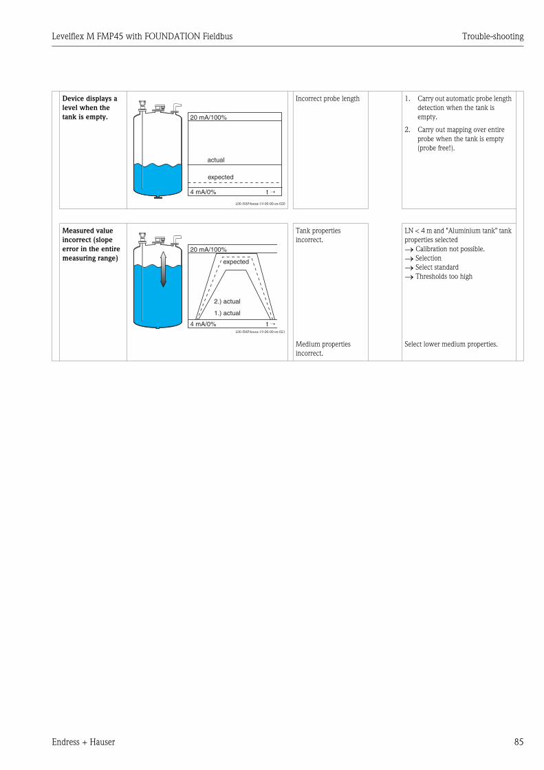
Levelflex M FMP45 with FOUNDATION Fieldbus Trouble-shooting
Endress + Hauser 85
Device displays a
level when the
tank is empty.
L00-FMP4xxxx-19-00-00-en-020
Incorrect probe length 1. Carry out automatic probe length
detection when the tank is
empty.
2. Carry out mapping over entire
probe when the tank is empty
(probe free!).
Measured value
incorrect (slope
error in the entire
measuring range)
L00-FMP4xxxx-19-00-00-en-021
Tank properties
incorrect.
LN < 4 m and "Aluminium tank" tank
properties selected
→ Calibration not possible.
→ Selection
→ Select standard
→ Thresholds too high
Medium properties
incorrect.
Select lower medium properties.
20 mA/100%
4 mA/0% t →
actual
expected
20 mA/100%
4 mA/0% t →
2.) actual
1.) actual
expected
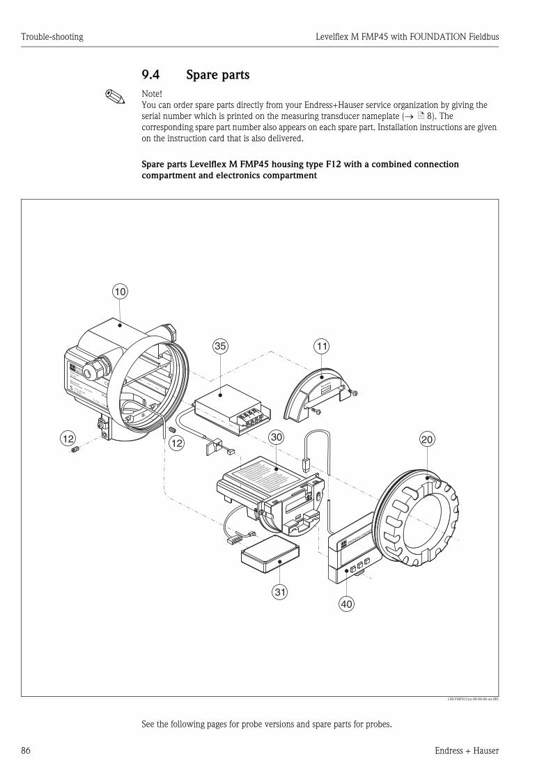
Trouble-shooting Levelflex M FMP45 with FOUNDATION Fieldbus
86 Endress + Hauser
9.4 Spare parts
! Note!
You can order spare parts directly from your Endress+Hauser service organization by giving the
serial number which is printed on the measuring transducer nameplate (→ ä 8). The
corresponding spare part number also appears on each spare part. Installation instructions are given
on the instruction card that is also delivered.
Spare parts Levelflex M FMP45 housing type F12 with a combined connection
compartment and electronics compartment
L00-FMP41Cxx-00-00-06-xx-001
See the following pages for probe versions and spare parts for probes.
ENDRESS+HAUSER
MICROPILOT II
IP 65
Order Code:Ser.-No.:
MessbereichMeasuring rangeU 16...36 V DC
4...20 mA
max. 20 m
Ma
de
in G
erm
any
Ma
ulb
urg
Ma
de
in G
erm
any
Ma
ulb
urg
T>70°C :
A
t >85°C
12
34
Terminal
ENDRESS+HAUSER
Achtung bei Abziehen des Koax-Steckers
(z.B. HF-Modul Wechsel) im Ex-Bereich:
Es ist sicherzustellen, dass bei abgezogen-
em Koax-Stecker keine elektrostatische
Aufladung (isolierte Kapazität) der Sonde
erfolgt (z.B. durch Befüllen oder Entleeren).
Bei Reparaturen Koax-Stecker sofort
wieder aufstecken!
35
1212
10
11
30
4031
20

Levelflex M FMP45 with FOUNDATION Fieldbus Trouble-shooting
Endress + Hauser 87
10 Housing
52008556 Housing F12, aluminium, M20, FF connector
52013409 Housing F12, aluminium, coated, M20, metal
52013348 Housing F12, aluminium, coated, G1/2, 4-wire
52013349 Housing F12, aluminium, coated, NPT1/2, 4-wire
52013350 Housing F12, aluminium, coated, M20, 4-wire
52013351 Housing F12, aluminium, coated, M20, metal
543120-0022 Housing F12, aluminium, G1/2
543120-0023 Housing F12, aluminium, NPT1/2
543120-0024 Housing F12, aluminium, M20
11 Hood for terminal compartment
52006026 Cover for the connection compartment F12
52019062 Cover for the connection compartment F12, FHX40
12 Set of screws
535720-9020 Set of screws for housing F12/T12
20 Cover
52005936 Cover F12/T12 aluminium, inspection glass, seal
517391-0011 Cover F12/T12 aluminium, coated, seal
30 Electronics
52013243 Electronics LEVELFLEX-M, Ex, FOUNDATION Fieldbus
31 HF module
52019780 HF module LEVELFLEX-M
35 Terminal module / power unit
52012156 Terminal module 4-pin, PROFIBUS PA, Foundation Fieldbus
52013304 Power unit, 10.5...32V DC (housing F12) for electronics, 4-wire
52013305 Power unit, 90 ...250V AC (housing F12) for electronics, 4-wire
52015585 Power unit, CSA, 10.5...32V DC (housing F12) for electronics, 4-wire
52015586 Power unit, CSA, 90...250V AC (housing F12) for electronics, 4-wire
40 Display
52005585 Display/operating module VU331

Trouble-shooting Levelflex M FMP45 with FOUNDATION Fieldbus
88 Endress + Hauser
Spare parts for Levelflex M FMP45 housing type F23
20 Cover
52018670 Cover F23 316L, sight glass, gasket
52018681 Cover F23 316L, gasket

Levelflex M FMP45 with FOUNDATION Fieldbus Trouble-shooting
Endress + Hauser 89
Spare parts for Levelflex M FMP45 housing type T12 with separate connecting
compartment
L00-FMP41Cxx-00-00-06-xx-002
ENDRESS+HAUSER
MICROPILOT FMR
IP 65
Order Code:Ser.-No.:
MessbereichMeasuring rangeU 16...36 V DC
4...20 mA
max. 20 m
Made in
Germ
any
M
aulb
urg
Made in
Germ
any
M
aulb
urg
T>70°C :
A
t >85°C
ENDRESS+HAUSER
Achtung bei Abziehen des Koax-Steckers
(z.B. HF-Modul Wechsel) im Ex-Bereich:
Es ist sicherzustellen, dass bei abgezogen-
em Koax-Stecker keine elektrostatische
Aufladung (isolierte Kapazität) der Sonde
erfolgt (z.B. durch Befüllen oder Entleeren).
Bei Reparaturen Koax-Stecker sofort
wieder aufstecken!
25
35
1212
10
11
30
40
31
20

Trouble-shooting Levelflex M FMP45 with FOUNDATION Fieldbus
90 Endress + Hauser
10 Housing
52006205 Housing T12, aluminium, M20, PEL, cover
52013410 Housing T12, aluminium, M20, FF connector, cover
543180-1023 Housing T12, aluminium, NPT1/2, PEL
11 Hood for terminal compartment
52005643 Hood T12
12 Set of screws
535720-9020 Set of screws for housing F12/T12
20 Cover
52005936 Cover F12/T12 aluminium, inspection glass, seal
517391-0011 Cover F12/T12 aluminium, coated, seal
25 Cover for the connection compartment
518710-0020 Cover T3/T12, aluminium, coated, seal
30 Electronics
52013243 Electronics LEVELFLEX-M, Ex, FOUNDATION Fieldbus
31 HF module
52019780 HF module LEVELFLEX-M
35 Terminal module / power unit
52013303 Terminal module Ex d, 2-pin, 2-wire, PROFIBUS PA, Foundation Fieldbus, T12
52018950 Terminal module EEx ia, 4-pin, PROFIBUS PA, Foundation Fieldbus, T12, OVP
40 Display
52005585 Display/operating module VU331
FMP45 - probes, accessories and spare parts
Under development.
Levelflex M FMP45 with FOUNDATION Fieldbus Trouble-shooting
Endress + Hauser 91
9.5 Return
The following procedures must be carried out before a transmitter is sent to Endress+Hauser e.g.
for repair or calibration:
• Remove all residue which may be present. Pay special attention to the gasket grooves and crevices
where fluid may be present. This is especially important if the fluid is dangerous to health, e.g.
corrosive, poisonous, carcinogenic, radioactive, etc.
• Always enclose a duly completed "Declaration of contamination" form (a copy of the “Declaration
of contamination” is included at the end of this operating manual). Only then can Endress
+Hauser transport, examine and repair a returned device.
• Enclose special handling instructions if necessary, for example a safety data sheet as per EN 91/
155/EEC.
Additionally specify:
• An exact description of the application
• The chemical and physical characteristics of the product
• A short description of the error that occurred (specify error code if possible)
• If necessary, give the error code
9.6 Disposal
In case of disposal please seperate the different components according to their material consistence.
9.7 Software history
9.8 Contact addresses of Endress+Hauser
Contact addresses can be found on our homepage: www.endress.com/worldwide. If you have any
questions, please do not hesitate to contact your Endress+Hauser representative.
Software version / Date Software changed Documentation changes
V 01.02.02 / 08.2003 Original software.
Operated via:
– ToF Tool
– Commuwin II (as of Version 2.08-1 Update C)
– HART-Communicator DXR375 withRev. 1, DD 1.
V 01.02.04 / 07.2004 "mapping" function improved Specification of the measuring accuracy at the end of probe
V 01.02.06 / 01.2005 Function "cho lost" improved
V 01.04.00 / 03.2006 function "detection window" • Description of Instrument Functions
• Operating menu extended see Cap. 11.1
Technical data Levelflex M FMP45 with FOUNDATION Fieldbus
92 Endress + Hauser
10 Technical data
10.1 Additional technical data
10.1.1 Input
Measured variable The measured variable is the distance between a reference point (see Fig. on → ä 14) and the
product surface.
Subject to the input empty distance (E, see Fig. on → ä 102), the level is calculated.
Alternatively, the level can be converted by means of linearisation (32 points) into other variables
(volume, mass).
10.1.2 Output
Output signal Foundation Fieldbus
Signal on alarm Error information can be accessed via the following interfaces:
• Local display:
– Error symbol (→ ä 34)
– Plain text display
• Current output, signal on error can be selected (e.g. according to NAMUR recommendation NE
43).
• Digital interface
Linearization The Levelflex M linearisation function enables conversion of the measured value into any desired
length or volume units and mass or %. Linearisation tables for volume calculation in cylindrical tanks
are pre-programmed. Any other tables from up to 32 value pairs can be input manually or semi-
automatically.
The creation of a linearisation table with the ToF Tool or FieldCare is particularly convenient.
10.1.3 Performance characteristics
Reference operating
conditions
• temperature = +20 °C (68 °F) ±5 °C (9 °F)
• pressure = 1013 mbar abs. (14.7 psia) ±20 mbar (0.3 psi)
• humidity = 65 % ±20%
• Reflection factor ≥ 0.8 (surface of the water for coax probe, metal plate for rod and rope probe
with min. 1 m ∅)
• Flange for rod or rope probe ≥ 30 cm ∅• Distance to obstructions ≥ 1 m
Maximum measured error Is in Function group "basic setup" (00) starting from → ä 58.
Resolution • digital: 1 mm
Reaction time The reaction time is dependent on the configuration.
Shortest time:
• 2-wire electronics: 1 s
Influence of ambiente
temperature
The measurements are carried out in accordance with EN 61298-3:
• digital output (HART, PROFIBUS PA, Foundation Fieldbus):
– average TK: 0.6 mm/10 K, max. ±3.5 mm over the entire temperature range -40 °C...+80 °C

Levelflex M FMP45 with FOUNDATION Fieldbus Technical data
Endress + Hauser 93
Influence of gaslayer High pressures reduce the propagation velocity of the measuring signals in the gas/vapor above the
fluid. This effect depends on the gas/vapor and is particularly large for low temperatures. This
results in a measuring error that gets bigger as the distance increases between the device zero point
(flange) and product surface. The following table illustrates this measured error for a few typical
gases/vapors (with regard to the distance; a positive value means that too large a distance is being
measured):
Special versions of FMP45 are available which provide a compensation method for the gas phase
influence. Please contact your local Endress+Hauser representative.
Gaslayer Temperature Pressure
°C °F 1 bar/14.5 psi 10 bar/145 psi 50 bar/725 psi 100 bar/1450 psi 200 bar/2900 psi 400 bar/5801 psi
Air
Nitrogen
20 68 0,00 % 0,22 % 1,2 % 2,4 % 4,9 % 9,5 %
200 392 -0,01 % 0,13 % 0,74 % 1,5 % 3,0 % 6,0 %
400 752 -0,02 % 0,08 % 0,52 % 1,1 % 2,1 % 4,2 %
Hydrogen 20 68 -0,01 % 0,10 % 0,61 % 1,2 % 2,5 % 4,9 %
200 392 -0,02 % 0,05 % 0,37 % 0,76 % 1,6 % 3,1 %
400 752 -0,02 % 0,03 % 0,25 % 0,53 % 1,1 % 2,2 %
Gaslayer Temperatuer Pressure
°C °F 1 bar/14.5 psi 10 bar/145 psi 50 bar/725 psi 100 bar/1450 psi 200 bar/2900 psi
Water
(saturated
steam)
100 212 0,20 % — — — —
180 356 — 2,1 % — — —
263 505,4 — — 8,6 % — —
310 590 — — — 22 % —
364 687,2 — — — — 58 %
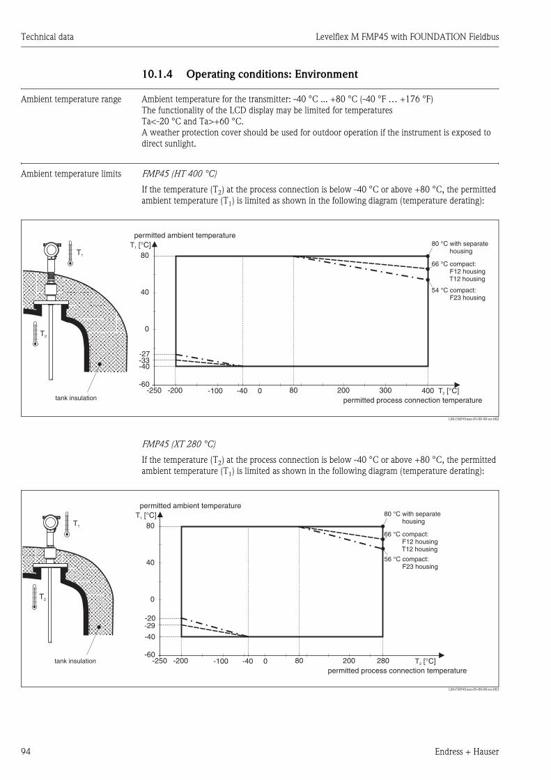
Technical data Levelflex M FMP45 with FOUNDATION Fieldbus
94 Endress + Hauser
10.1.4 Operating conditions: Environment
Ambient temperature range Ambient temperature for the transmitter: -40 °C ... +80 °C (-40 °F … +176 °F)
The functionality of the LCD display may be limited for temperatures
Ta<-20 °C and Ta>+60 °C.
A weather protection cover should be used for outdoor operation if the instrument is exposed to
direct sunlight.
Ambient temperature limits FMP45 (HT 400 °C)
If the temperature (T2) at the process connection is below -40 °C or above +80 °C, the permitted
ambient temperature (T1) is limited as shown in the following diagram (temperature derating):
L00-FMP45xxx-05-00-00-en-002
FMP45 (XT 280 °C)
If the temperature (T2) at the process connection is below -40 °C or above +80 °C, the permitted
ambient temperature (T1) is limited as shown in the following diagram (temperature derating):
L00-FMP45xxx-05-00-00-en-003
T2 [°C]
T1 [°C]
-200-250 0-100 -40-60
-40-33-27
0
40
80 200 300 400
80
T2
T1
permitted process connection temperature
permitted ambient temperature80 °C with separate
housing
54 °C compact:F23 housing
66 °CF12 housingT12 housing
compact:
tank insulation
T2 [°C]
T1 [°C]
-200-250 0-100 -40-60
-40
-29-20
0
40
80 200 280
80
T2
T1
permitted process connection temperature
permitted ambient temperature80 °C with separate
housing
56 °C compact:F23 housing
66 °CF12 housingT12 housing
compact:
tank insulation

Levelflex M FMP45 with FOUNDATION Fieldbus Technical data
Endress + Hauser 95
Storage temperature -40 °C … +80 °C (-40 °F … +176°F)
Climate class DIN EN 60068-2-38 (test Z/AD)
Vibration resistance DIN EN 60068-2-64 / IEC 68-2-64: 20…2000 Hz, 1 (m/s2)2/Hz
Cleaning the probe Depending on the application, soilings or sediments can accumulate on the probe. A thin, even layer
only influences measurement slightly. Thick layers can dampen the signal and then reduce the
measuring range. Heavy, uneven build-up, adhesion e.g. through crystallisation, can lead to
incorrect measurement. In this case, we recommend that you use a non-contact measuring
principle, or check the probe regularly for soiling
Electromagnetic
compatibility (EMC)
When installing the probes in metal and concrete tanks and when using a coax probe:
• Interference Emission to EN 61326, Electrical Equipment Class B
• Interference immunity to EN 61326, Annex A (Industrial area) and NAMUR Recommendation
NE 21 (EMC)
The measured value can be affected by strong electromagnetic fields when installing rod and rope
probes without a shielding/metallic wall, e.g. plastic, and in wooden silos.
• Interference emission to EN 61326, Class A equipment.
• Interference immunity: the measured value can be affected by strong electromagnetic fields.
10.1.5 Operating conditions: Process
Process temperature range The maximum permitted temperature at the process connection (see Figure for measuring point) is
determined by the process connection ordered:
L00-FMP45xxx-05-00-00-de-001
Process pressure limits See pressure/temperature diagram on this page.
The specified rage may be reduced by the selected process connection.
The pressure rating (PN) specified on the flanges refers to a reference temperature of 20 °C, for
ASME flanges to 100 °F.
FMP45: process pressure depending on the process temperature
350
300
400 400 400 400
380
0
50
100
150
200
250
300
350
400
450
1 2 3 4 5 6 7-60oC 0oC 100oC 200oC 300oC 400oC
Pressure [bar]
-200oC -100
oC 0
oC 100
oC 200
oC 300
oC 400
oC
280 °C Temp. [oC]
FMP45 XT FMP45 HT
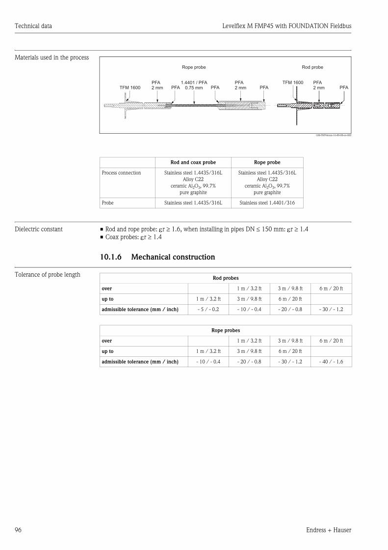
Technical data Levelflex M FMP45 with FOUNDATION Fieldbus
96 Endress + Hauser
Materials used in the process
L00-FMP4xxxx-16-00-00-en-002
Dielectric constant • Rod and rope probe: εr ≥ 1.6, when installing in pipes DN ≤ 150 mm: εr ≥ 1.4
• Coax probes: εr ≥ 1.4
10.1.6 Mechanical construction
Tolerance of probe length
Rod and coax probe Rope probe
Process connection Stainless steel 1.4435/316L
Alloy C22
ceramic Al2O3, 99.7%
pure graphite
Stainless steel 1.4435/316L
Alloy C22
ceramic Al2O3, 99.7%
pure graphite
Probe Stainless steel 1.4435/316L Stainless steel 1.4401/316
TFM 1600TFM 1600PFA
2 mmPFA2 mm
PFA2 mmPFA PFAPFA PFA
1.4401 / PFA0.75 mm
Rope probe Rod probe
Rod probes
over 1 m / 3.2 ft 3 m / 9.8 ft 6 m / 20 ft
up to 1 m / 3.2 ft 3 m / 9.8 ft 6 m / 20 ft
admissible tolerance (mm / inch) - 5 / - 0.2 - 10 / - 0.4 - 20 / - 0.8 - 30 / - 1.2
Rope probes
over 1 m / 3.2 ft 3 m / 9.8 ft 6 m / 20 ft
up to 1 m / 3.2 ft 3 m / 9.8 ft 6 m / 20 ft
admissible tolerance (mm / inch) - 10 / - 0.4 - 20 / - 0.8 - 30 / - 1.2 - 40 / - 1.6

Levelflex M FMP45 with FOUNDATION Fieldbus Technical data
Endress + Hauser 97
Weight
Material • Housing:
– housing F12/T12: aluminium (AlSi10Mg), seawater-resistant, chromated, powder-coated
– housing F23: 316L, corrosion-resistant steel
• Sight window: glass
Levelflex M
FMP45
XT version (max. 280 °C) HT version (max. 400 °C)
Rod probe Rope probe Coax probe Rod probe Rope probe Coax probe
Weight with F12 or
T12 housing
approx. 8.5 kg
+
approx. 1.6 kg/m
Probe length
+
Flange weight
approx. 8.5 kg
+
approx. 0.1 kg/m
Probe length
+
Flange weight
approx. 8.5 kg
+
approx. 3.5 kg/m
Probe length
+
Flange weight
approx. 9.5 kg
+
approx. 1.6 kg/m
Probe length
+
Flange weight
approx. 9.5 kg
+
approx. 0.1 kg/m
Probe length
+
Flange weight
approx. 9.5 kg
+
approx. 3.5 kg/m
Probe length
+
Flange weight
Weight with F23
housing
approx. 12 kg
+
approx. 1.6 kg/m
Probe length
+
Flange weight
approx. 12 kg
+
approx. 0.1 kg/m
Probe length
+
Flange weight
approx. 12 kg
+
approx. 3.5 kg/m
Probe length
+
Flange weight
approx. 13 kg
+
approx. 1.6 kg/m
Probe length
+
Flange weight
approx. 13 kg
+
approx. 0.1 kg/m
Probe length
+
Flange weight
approx. 13 kg
+
approx. 3.5 kg/m
Probe length
+
Flange weight
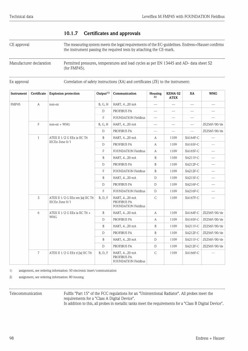
Technical data Levelflex M FMP45 with FOUNDATION Fieldbus
98 Endress + Hauser
10.1.7 Certificates and approvals
CE approval The measuring system meets the legal requirements of the EC-guidelines. Endress+Hauser confirms
the instrument passing the required tests by attaching the CE-mark.
Manufacturer declaration Permitted pressures, temperatures and load cycles as per EN 13445 and AD- data sheet S2
(for FMP45).
Ex approval Correlation of safety instructions (XA) and certificates (ZE) to the instrument:
Telecommunication Fulfils "Part 15" of the FCC regulations for an "Unintentional Radiator". All probes meet the
requirements for a "Class A Digital Device".
In addition to this, all probes in metallic tanks meet the requirements for a "Class B Digital Device".
Instrument Certificate Explosion protection Output1)) Communication Housing 2))
KEMA 02
ATEX
XA WHG
FMP45 A non-ex B, G, H HART, 4...20 mA — — — —
D PROFIBUS PA — — — —
F FOUNDATION Fieldbus — — — —
F non-ex + WHG B, G, H HART, 4...20 mA — — — ZE256F/00/de
D PROFIBUS PA — — — ZE256F/00/de
1 ATEX II 1/2 G EEx ia IIC T6
IECEx Zone 0/1
B HART, 4...20 mA A 1109 XA164F-C —
D PROFIBUS PA A 1109 XA165F-C —
F FOUNDATION Fieldbus A 1109 XA165F-C —
B HART, 4...20 mA B 1109 XA211F-C —
D PROFIBUS PA B 1109 XA212F-C —
F FOUNDATION Fieldbus B 1109 XA212F-C —
B HART, 4...20 mA D 1109 XA215F-C —
D PROFIBUS PA D 1109 XA216F-C —
F FOUNDATION Fieldbus D 1109 XA216F-C —
3 ATEX II 1/2 G EEx em [ia] IIC T6
IECEx Zone 0/1
B, D, F HART, 4...20 mA
PROFIBUS PA
FOUNDATION Fieldbus
C 1109 XA167F-C —
6 ATEX II 1/2 G EEx ia IIC T6 +
WHG
B HART, 4...20 mA A 1109 XA164F-C ZE256F/00/de
D PROFIBUS PA A 1109 XA165F-C ZE256F/00/de
B HART, 4...20 mA B 1109 XA211F-C ZE256F/00/de
D PROFIBUS PA B 1109 XA212F-C ZE256F/00/de
B HART, 4...20 mA D 1109 XA211F-C ZE256F/00/de
D PROFIBUS PA D 1109 XA212F-C ZE256F/00/de
7 ATEX II 1/2 G EEx d [ia] IIC T6 B, D, F HART, 4...20 mA
PROFIBUS PA
FOUNDATION Fieldbus
C 1109 XA166F-C —
1) assignment, see ordering information: 50 electronic insert/communication
2) assignment, see ordering information: 80 housing

Levelflex M FMP45 with FOUNDATION Fieldbus Technical data
Endress + Hauser 99
External standards and
guidelines
EN 60529
Protection class of housing (IP-code)
EN 61010
Safety regulations for electrical devices for measurement, control, regulation and laboratory use.
EN 61326
Emissions (equipment class B), compatibility (appendix A - industrial area)
NAMUR NE 21
Electromagnetic Compatibility (EMC) of Industrial Process and Laboratory Control Equipment.
NAMUR NE 43
Standardization of the Signal Level for the Failure Information of Digital Transmitters.
Pressure Equipment Directive The FMP45 corresponds to the 97/23/EC Directive (Pressure Equipment Directive). It is a pressure
accessory with a volume < 0.1 l, corresponding to Category I.
Conformity assessment was carried out as per Module A, the design as per EN 13445 and AD 2000
technical specifications. FMP45 is not suitable for use with unstable gases at nominal pressures
above 200 bar.
10.1.8 Supplementary Documentation
! Note!
This supplementary documentation can be found on our product pages on www.endress.com.
• Technical Information (TI386F/00/en)
• Safety Manual "Functional safety manual" (SD174F/00/en)
• Certificate "Allgemeine bauaufsichtliche Zulassung" (ZE256F/00/de)

Appendix Levelflex M FMP45 with FOUNDATION Fieldbus
100 Endress + Hauser
11 Appendix
11.1 Operating menu PA (Display modul), ToF Tool
L00-FMP4xxxx-19-00-01-en-022
safety settings
basic setup
output on alarm
MIN
holdMAX
standardaluminium tankplastic tankbypass / pipecoax probeconcrete wall
unknownDC: 1.4 … 1.6DC: 1.6 … 1.9DC: 1.9 … 2.5DC: 2.5 … 4DC: 4 … 7DC: > 7
standardfast changeslow changetest: no filter
tank properties
end of probe
freetie down isolatedtie down gnd.
enter value
medium cond.
outp. echo loss
alarmhold
ramp %MB/min
process proper.
ramp %span/min
empty calibr.enter value
delay time
in case of echo lossmax. 4000 sec.default: 30 s
length adjustment
01
00
010
002
030
003
012
004
013
005
014
03 probe lengthnot modified
modified
probe
free
probe length
probe length
determine length
length OK
031
032 033
033
034
level/ullage.
level DUullage DU
level CUullage CU
Selectionmapping
common
delete map.
envelope curvesubstracted signalmapping
single curvecyclic
plot settings
present error
linearisation
manualsemi-automatictable on
horizontal cyl
linear
clear table
dist./meas.valueD and L is displayed
recording curve
language
previous error
customer unit
table no.input levelinput volume
customer unit
customer unit
check distancedistance = ok
dist. unknowndist. too big
back to homeenter timeDefault: 900 s
EnglishDeutschFrancaisEspanolItalianoNederlandsKatakana (japanese)
clear last error
linearisation
range of mapping
pres. Map dist.
input of mappingrange
is displayed
resetfor reset codesee manual
next point
no
yes
start mapping
delete map.
offon
no
yes
no.of decimalsxx.xx.xxx.xxx
unlock parameterfor enter codesee manual
linearisation
extended calibr.
envelope curve
display
diagnostics
040
050
0E1
0A0
041
008
0E2
092
0A1
042
043
043
044045
042
042
051
093
0A2
052
054
0A3
045
053
055
095
0A4
04
05
0E
09
0A
format displaydecimal
094
1/16”
manualprobe freedist. too small
covered
see Function group “leghth adjustment 03”end of probe 030 determine length 034
too shorttoo long
output 06
device id protocol+sw-no. dd rev.system parameter 0C1 0C2 0C40C device tag dev. rev.0C0 0C3
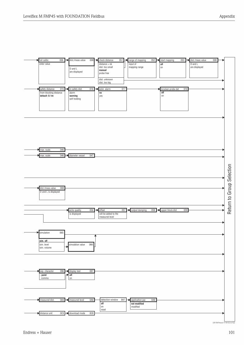
Levelflex M FMP45 with FOUNDATION Fieldbus Appendix
Endress + Hauser 101
L00-FMP4xxxx-19-00-02-en-022
safety distancefrom blocking distancedefault: 0.1m
dist./meas.value
D and Lare displayed
in safety dist.alarm
self holdingwarning
check distance
distance = okdist. too small
probe freemanual
dist. unknowndist. too big
ackn. alarmnoyes
range of mapping
input ofmapping range
Retu
rn to
Gro
up S
elec
tion
start mappingfull calibr.enter value
dist./meas.value
brocken probe det
D and Lare displayed
015
008
016
051
017
052 053006 008
019
dist./meas.valueD und L is displayed
sep. character
. point, comma
measured dist.
max. scale
max. scale
echo qualityis displayed
display test
offon
offon
offon
measured level
diameter vessel
offsetwill be added to themeasured level
output damping
application par.not modifiedmodified
upper block.dist
008
096
0A5
046
046
056
097
0A6
047
057 058
0A8
059
simulation
sim. offsim. levelsim. volume
simulation value
065
066
distance unit download mode0C5 0C8
detection windowoffonreset
0A7
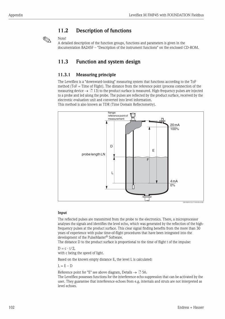
Appendix Levelflex M FMP45 with FOUNDATION Fieldbus
102 Endress + Hauser
11.2 Description of functions
! Note!
A detailed description of the function groups, functions and parameters is given in the
documentation BA245F – "Description of the instrument functions" on the enclosed CD-ROM.
11.3 Function and system design
11.3.1 Measuring principle
The Levelflex is a "downward-looking" measuring system that functions according to the ToF
method (ToF = Time of Flight). The distance from the reference point (process connection of the
measuring device → ä 13) to the product surface is measured. High-frequency pulses are injected
to a probe and led along the probe. The pulses are reflected by the product surface, received by the
electronic evaluation unit and converted into level information.
This method is also known as TDR (Time Domain Reflectometry).
L00-FMP41Cxx-15-00-00-en-001
Input
The reflected pulses are transmitted from the probe to the electronics. There, a microprocessor
analyses the signals and identifies the level echo, which was generated by the reflection of the high-
frequency pulses at the product surface. This clear signal finding benefits from the more than 30
years of experience with pulse time-of-flight procedures that have been integrated into the
development of the PulseMaster® Software.
The distance D to the product surface is proportional to the time of flight t of the impulse:
D = c · t/2,
with c being the speed of light.
Based on the known empty distance E, the level L is calculated:
L = E – D
Reference point for "E" see above diagram, Details → ä 56.
The Levelflex possesses functions for the interference echo suppression that can be activated by the
user. They guarantee that interference echoes from e.g. internals and struts are not interpreted as
level echoes.
20mA100%
4mA0%
D
L
F
E
flange:referencepointofmeasurement
probe lengthLN
Levelflex M FMP45 with FOUNDATION Fieldbus Appendix
Endress + Hauser 103
11.3.2 Equipment architecture
Stand-alone
The Levelflex M can be used for measurement in a stilling well / bypass as well as in free space.
System integration via FOUNDATION Fieldbus
The system integration via FOUNDATION Fieldbus is described in → Kap. 5.5.
On-site operation:
• with display and operating module VU331,
• with a Personal Computer, FXA193 (RS232C) or FXA291 and ToF Adapter FXA291 (USB) and
the operating software "ToF Tool - FieldTool Package" respectively "FieldCare".
The ToF Tool is a graphical operating software for instruments from Endress+Hauser that operate
based on the time-of-flight principle (radar, ultrasonic, guided micro-impulse). It assists with
commissioning, securing data, signal analysis and documentation of the measuring point.
Remote operation
• with a Personal Computer, a Fieldbus H1 card (e.g. NI Fieldbus Interface Board) and a network
configuration software (e.g. NI-FBUS configurator) and the operating software ToF Tool.
11.3.3 Patents
This product may be protected by at least one of the following patents.
Further patents are pending.
• US 5,661,251 i EP 0 780 664
• US 5,827,985 i EP 0 780 664
• US 5,884,231 i EP 0 780 665
• US 5,973,637 i EP 0 928 974

Appendix Levelflex M FMP45 with FOUNDATION Fieldbus
104 Endress + Hauser

Levelflex M FMP45 with FOUNDATION Fieldbus Index
Endress + Hauser 105
Index
AAccessories . . . . . . . . . . . . . . . . . . . . . . . . . . . . . . . . . . . . 78
Alarm . . . . . . . . . . . . . . . . . . . . . . . . . . . . . . . . . . . . . . . . 38
Application errors . . . . . . . . . . . . . . . . . . . . . . . . . . . . . . . 84
BBasic Setup . . . . . . . . . . . . . . . . . . . . . . . . . . . . . . 56, 58, 71
Blocking distance . . . . . . . . . . . . . . . . . . . . . . . . . . . . . . . 66
CCE mark . . . . . . . . . . . . . . . . . . . . . . . . . . . . . . . . . . . . . . 11
Commissioning . . . . . . . . . . . . . . . . . . . . . . . . . . . . . . . . . 55
Ddeclaration of conformity. . . . . . . . . . . . . . . . . . . . . . . . . . 11
degree of protection . . . . . . . . . . . . . . . . . . . . . . . . . . . . . 30
Designated use . . . . . . . . . . . . . . . . . . . . . . . . . . . . . . . . . . 6
Determine length . . . . . . . . . . . . . . . . . . . . . . . . . . . . . . . 61
Dimensions . . . . . . . . . . . . . . . . . . . . . . . . . . . . . . . . . . . . 13
Display . . . . . . . . . . . . . . . . . . . . . . . . . . . . . . . . . . . . . . . 33
EEmpty calibration . . . . . . . . . . . . . . . . . . . . . . . . . . . . . . . 62
End of probe . . . . . . . . . . . . . . . . . . . . . . . . . . . . . . . . . . . 72
Engineering hints . . . . . . . . . . . . . . . . . . . . . . . . . . . . . . . 22
Envelope curve . . . . . . . . . . . . . . . . . . . . . . . . . . . . . . 68, 75
Error messages . . . . . . . . . . . . . . . . . . . . . . . . . . . . . . 38, 82
Ersatzteile . . . . . . . . . . . . . . . . . . . . . . . . . . . . . . . . . . . . . 89
Ex(-)approval . . . . . . . . . . . . . . . . . . . . . . . . . . . . . . . . . . 98
Exterior cleaning . . . . . . . . . . . . . . . . . . . . . . . . . . . . . . . . 77
Ex-Zulassung . . . . . . . . . . . . . . . . . . . . . . . . . . . . . . . . . . . 8
FF12 housing . . . . . . . . . . . . . . . . . . . . . . . . . . . . . . . . . . . 26
FHX40 . . . . . . . . . . . . . . . . . . . . . . . . . . . . . . . . . . . . . . . 80
fieldbus plug connectors . . . . . . . . . . . . . . . . . . . . . . . . . . 28
FOUNDATION Fieldbus . . . . . . . . . . . . . . . . . . . . . . . . . . 40
Foundation Fieldbus connector . . . . . . . . . . . . . . . . . . . . . 28
Full calibration . . . . . . . . . . . . . . . . . . . . . . . . . . . . . . . . . 62
IInterference echo mapping . . . . . . . . . . . . . . . . . . . . . . . . 74
KKey assignment . . . . . . . . . . . . . . . . . . . . . . . . . . . . . . . . . 34
LLock . . . . . . . . . . . . . . . . . . . . . . . . . . . . . . . . . . . . . . . . . 35
MMaintenance . . . . . . . . . . . . . . . . . . . . . . . . . . . . . . . . . . . 77
Media group . . . . . . . . . . . . . . . . . . . . . . . . . . . . . . . . . . . 59
Medium properties . . . . . . . . . . . . . . . . . . . . . . . . . . . 59, 72
Mounting . . . . . . . . . . . . . . . . . . . . . . . . . . . . . . . . . . . . . 12
NNameplate . . . . . . . . . . . . . . . . . . . . . . . . . . . . . . . . . . . . . 8
OOperating menu . . . . . . . . . . . . . . . . . . . . . . . . . . . . . . . . 32
Operation . . . . . . . . . . . . . . . . . . . . . . . . . . . . . . . . . . 31, 35
Operational safety . . . . . . . . . . . . . . . . . . . . . . . . . . . . . . . . 6
Ordering structure . . . . . . . . . . . . . . . . . . . . . . . . . . . . . . . . 8
PProbe . . . . . . . . . . . . . . . . . . . . . . . . . . . . . . . . . . . . . . . . 73
Probe length . . . . . . . . . . . . . . . . . . . . . . . . . . . . . . . . . . . 73
Process properties . . . . . . . . . . . . . . . . . . . . . . . . . . . . 60, 72
RRepairs . . . . . . . . . . . . . . . . . . . . . . . . . . . . . . . . . . . . . . . 77
Repairs to Ex-approved devices . . . . . . . . . . . . . . . . . . . . . 77
Replacement . . . . . . . . . . . . . . . . . . . . . . . . . . . . . . . . . . . 77
Reset . . . . . . . . . . . . . . . . . . . . . . . . . . . . . . . . . . . . . . . . . 37
Return. . . . . . . . . . . . . . . . . . . . . . . . . . . . . . . . . . . . . . . . 91
SSafety conventions and symbols . . . . . . . . . . . . . . . . . . . . . . 7
Service Interface FXA291. . . . . . . . . . . . . . . . . . . . . . . . . . 79
Software history. . . . . . . . . . . . . . . . . . . . . . . . . . . . . . . . . 91
Spare parts. . . . . . . . . . . . . . . . . . . . . . . . . . . . . . . . . . . . . 86
spare parts . . . . . . . . . . . . . . . . . . . . . . . . . . . . . . . . . . . . . 90
System error messages . . . . . . . . . . . . . . . . . . . . . . . . . . . . 82
TT12 housing . . . . . . . . . . . . . . . . . . . . . . . . . . . . . . . . . . . 27
Tank properties . . . . . . . . . . . . . . . . . . . . . . . . . . . . . . . . . 72
Technical data . . . . . . . . . . . . . . . . . . . . . . . . . . . . . . . . . . 92
ToF Tool . . . . . . . . . . . . . . . . . . . . . . . . . . . . . . . 71, 75, 100
Trouble-shooting . . . . . . . . . . . . . . . . . . . . . . . . . . . . . . . . 81
Trouble-shooting instructions. . . . . . . . . . . . . . . . . . . . . . . 81
Turn housing. . . . . . . . . . . . . . . . . . . . . . . . . . . . . . . . . . . 25
UUnlock parameter . . . . . . . . . . . . . . . . . . . . . . . . . . . . . . . 36
VVU 331 . . . . . . . . . . . . . . . . . . . . . . . . . . . . . . . . . . . . . . . 68
WWarning . . . . . . . . . . . . . . . . . . . . . . . . . . . . . . . . . . . . . . 38
weather protection cover . . . . . . . . . . . . . . . . . . . . . . . . . . 78
Wiring. . . . . . . . . . . . . . . . . . . . . . . . . . . . . . . . . . . . . . . . 26

Levelflex M FMP45 with FOUNDATION Fieldbus Index
106 Endress + Hauser


www.endress.com/worldwide
BA281F/00/en/12.06
Nr. 52021043
CCS/FM+SGML 6.0/ProMoDo 52021043