levelflex m fmp40 and fmp45 - hyking.com · the levelflex m fmp40 and fmp45 is a compact level...
TRANSCRIPT

BA327F/00/en/03.05No. 52027874Valid as of software versionV 01.02.04 (amplifier)V 01.02.04 (communication)
Operating Instructions
Levelflex M FMP40 and FMP45Guided Level-Radar for interface measurement according to MVTFN0341HART/4...20 mA
6
Brief overview Levelflex M FMP40 and FMP45
2
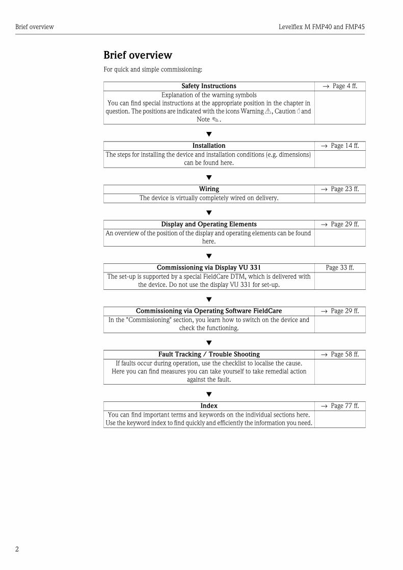
Brief overviewFor quick and simple commissioning:
Safety Instructions → Page 4 ff.Explanation of the warning symbols
You can find special instructions at the appropriate position in the chapter in question. The positions are indicated with the icons Warning #, Caution " and
Note !.
Æ
Installation → Page 14 ff.The steps for installing the device and installation conditions (e.g. dimensions)
can be found here.
Æ
Wiring → Page 23 ff.The device is virtually completely wired on delivery.
Æ
Display and Operating Elements → Page 29 ff.An overview of the position of the display and operating elements can be found
here.
Æ
Commissioning via Display VU 331 Page 33 ff.The set-up is supported by a special FieldCare DTM, which is delivered with
the device. Do not use the display VU 331 for set-up.
Æ
Commissioning via Operating Software FieldCare → Page 29 ff.In the "Commissioning" section, you learn how to switch on the device and
check the functioning.
Æ
Fault Tracking / Trouble Shooting → Page 58 ff.If faults occur during operation, use the checklist to localise the cause.
Here you can find measures you can take yourself to take remedial action against the fault.
Æ
Index → Page 77 ff.You can find important terms and keywords on the individual sections here.
Use the keyword index to find quickly and efficiently the information you need.

Levelflex M FMP40 and FMP45 Table of contents
3
Table of contents
1 Safety instructions . . . . . . . . . . . . . . . . 41.1 Designated use . . . . . . . . . . . . . . . . . . . . . . . . . . . . 41.2 Installation, commissioning and operation . . . . . . . . 41.3 Operational safety . . . . . . . . . . . . . . . . . . . . . . . . . . 41.4 Notes on safety conventions and icons . . . . . . . . . . . 5
2 Identification . . . . . . . . . . . . . . . . . . . . 62.1 Device designation . . . . . . . . . . . . . . . . . . . . . . . . . 62.2 Scope of delivery . . . . . . . . . . . . . . . . . . . . . . . . . . 132.3 Certificates and approvals . . . . . . . . . . . . . . . . . . . 132.4 Registered trademarks . . . . . . . . . . . . . . . . . . . . . . 13
3 Installation . . . . . . . . . . . . . . . . . . . . . 143.1 Quick installation guide . . . . . . . . . . . . . . . . . . . . . 143.2 Incoming acceptance, transport, storage . . . . . . . . . 153.3 Installation conditions . . . . . . . . . . . . . . . . . . . . . . 163.4 Installation . . . . . . . . . . . . . . . . . . . . . . . . . . . . . . 193.5 Turn housing . . . . . . . . . . . . . . . . . . . . . . . . . . . . . 223.6 Post-installation check . . . . . . . . . . . . . . . . . . . . . . 22
4 Wiring . . . . . . . . . . . . . . . . . . . . . . . . 234.1 Quick wiring guide . . . . . . . . . . . . . . . . . . . . . . . . 234.2 Connecting the measuring unit . . . . . . . . . . . . . . . 254.3 Recommended connection . . . . . . . . . . . . . . . . . . 284.4 Degree of protection . . . . . . . . . . . . . . . . . . . . . . . 284.5 Post-connection check . . . . . . . . . . . . . . . . . . . . . . 28
5 Operation . . . . . . . . . . . . . . . . . . . . . . 295.1 Display and operating elements . . . . . . . . . . . . . . . 295.2 Display and acknowledging error messages . . . . . . 31
6 Commissioning. . . . . . . . . . . . . . . . . . 326.1 Function check . . . . . . . . . . . . . . . . . . . . . . . . . . . 326.2 Switching on the measuring device . . . . . . . . . . . . 326.3 Basic Setup . . . . . . . . . . . . . . . . . . . . . . . . . . . . . . 33
7 Description of Instrument Functions . 397.1 Function group "basic setup" . . . . . . . . . . . . . . . . . 397.2 Function group "safety settings" . . . . . . . . . . . . . . . 417.3 Function group "length adjustment" . . . . . . . . . . . . 467.4 Function group "extended calibr." . . . . . . . . . . . . . 467.5 Function group "output" . . . . . . . . . . . . . . . . . . . . 477.6 Function group "display" . . . . . . . . . . . . . . . . . . . . 507.7 Function group "diagnostics" . . . . . . . . . . . . . . . . . 527.8 Function group "system parameters" . . . . . . . . . . . 547.9 Function group "service" . . . . . . . . . . . . . . . . . . . . 54
8 Maintenance . . . . . . . . . . . . . . . . . . . . 55
9 Accessories . . . . . . . . . . . . . . . . . . . . . 56
10 Trouble-shooting . . . . . . . . . . . . . . . . . 5810.1 Trouble-shooting instructions . . . . . . . . . . . . . . . . . 5810.2 System error messages . . . . . . . . . . . . . . . . . . . . . . 5910.3 Spare parts . . . . . . . . . . . . . . . . . . . . . . . . . . . . . . . 6010.4 Return . . . . . . . . . . . . . . . . . . . . . . . . . . . . . . . . . . 6410.5 Disposal . . . . . . . . . . . . . . . . . . . . . . . . . . . . . . . . . 6410.6 Software history . . . . . . . . . . . . . . . . . . . . . . . . . . . 6410.7 Contact addresses of Endress+Hauser . . . . . . . . . . . 64
11 Technical data . . . . . . . . . . . . . . . . . . . 6511.1 Additional technical data . . . . . . . . . . . . . . . . . . . . 65
12 Appendix . . . . . . . . . . . . . . . . . . . . . . . 7412.1 Function and system design . . . . . . . . . . . . . . . . . . 74
Index . . . . . . . . . . . . . . . . . . . . . . . . . . . . . . 77

Safety instructions Levelflex M FMP40 and FMP45
4
1 Safety instructions
1.1 Designated useThe Levelflex M FMP40 and FMP45 is a compact level transmitter for the continuous measurement of the interface level in liquids, measuring prinziple: Guided Level Radar / TDR: Time Domain Reflectometry.
1.2 Installation, commissioning and operationThe Levelflex M has been designed to operate safely in accordance with current technical, safety and EU standards. If installed incorrectly or used for applications for which it is not intended, however, it is possible that application-related dangers may arise, e.g. product overflow due to incorrect installation or calibration. For this reason, the instrument must be installed, connected, operated and maintained according to the instructions in this manual: personnel must be authorised and suitably qualified. The manual must have been read and understood, and the instructions followed. Modifications and repairs to the device are permissible only when they are expressly approved in the manual.
1.3 Operational safety
Hazardous areas
Measuring systems for use in hazardous environments are accompanied by separate "Ex documentation", which is an integral part of this Operating Manual. Strict compliance with the installation instructions and ratings as stated in this supplementary documentation is mandatory.
• Ensure that all personnel are suitably qualified.• Observe the specifications in the certificate as well as national and local regulations.

Levelflex M FMP40 and FMP45 Safety instructions
5
1.4 Notes on safety conventions and iconsIn order to highlight safety-relevant or alternative operating procedures in the manual, the following conventions have been used, each indicated by a corresponding symbol in the margin.
Safety conventions
#Warning!A warning highlights actions or procedures which, if not performed correctly, will lead to personal injury, a safety hazard or destruction of the instrument
"Caution!Caution highlights actions or procedures which, if not performed correctly, may lead to personal injury or incorrect functioning of the instrument
!Note!A note highlights actions or procedures which, if not performed correctly, may indirectly affect operation or may lead to an instrument response which is not planned
Explosion protection
0Device certified for use in explosion hazardous areaIf the device has this symbol embossed on its name plate it can be installed in an explosion hazardous area
-Explosion hazardous areaSymbol used in drawings to indicate explosion hazardous areas. Devices located in and wiring entering areas with the designation “explosion hazardous areas” must conform with the stated type of protection.
.Safe area (non-explosion hazardous area)Symbol used in drawings to indicate, if necessary, non-explosion hazardous areas. Devices located in safe areas still require a certificate if their outputs run into explosion hazardous areas
Electrical symbols
% Direct voltageA terminal to which or from which a direct current or voltage may be applied or supplied
&Alternating voltageA terminal to which or from which an alternating (sine-wave) current or voltage may be applied or supplied
)Grounded terminalA grounded terminal, which as far as the operator is concerned, is already grounded by means of an earth grounding system
*Protective grounding (earth) terminalA terminal which must be connected to earth ground prior to making any other connection to the equipment
+Equipotential connection (earth bonding)A connection made to the plant grounding system which may be of type e.g. neutral star or equipotential line according to national or company practice
Temperature resistance of the connection cablesStates, that the connection calbes must be resistant to a temperature of at least 85 °C.
t >85°C

Identification Levelflex M FMP40 and FMP45
6
2 Identification
2.1 Device designation
2.1.1 NameplateThe following technical data are given on the instrument nameplate:
L00-FMP4xxxx-18-00-00-en-001
Fig. 1: Information on the nameplate of the Levelflex M (example)
2.1.2 Ordering structureOrdering structure Levelflex M FMP40
Made in GermanyD-79689 Maulburg
Dat./Insp.:
Order Code:
IP68 / NEMA 6PSer.-No.:
4-wire
ENDRESS+HAUSER
t >85°CTA > 70°C :
D01301-A
if modificationsee sep. labelX = Patents
LEVELFLEX-M
90 … 253 V AC 3,5VA10,5 … 32 V DC 1W16 … 3 V DC 0,8W
Profibus PAFoundation Fieldbus
LN= PN=
4 … 20 mA HART 2-wire
Order No(see Order Information)
Communicationvariant andsupply voltage
Serial number
Reference to additionalsafety-relevant documentation
Designation according to Directive 94/9/ECand designation of protection
10 Approval:A Non-hazardous areaF Non-hazardous area, WHG1 ATEX II 1/2G EEx ia IIC T62 ATEX II 1/2D, Alu blind cover3 ATEX II 2G EEx em (ia) IIC T64 ATEX II 1/3D5 ATEX II 1/2G EEx ia IIC T6, ATEX II 1/3D6 ATEX II 1/2G EEx ia IIC T6, WHG7 ATEX II 1/2G EEx d (ia) IIC T68 ATEX II 1/2G EEx ia IIC T6, ATEX II 1/3D, WHGM FM DIP Cl.II Div.1 Gr.E-G N.I.S FM IS Cl.I,II,III Div.1 Gr.A-G N.I.T FM XP Cl.I,II,III Div.1 Gr.A-GN CSA General PurposeP CSA DIP Cl.II Div.1 Gr.G + coal dust, N.I.U CSA IS Cl.I,II,III Div.1 Gr.A-D,G + coal dust, N.I.V CSA IS Cl.I,II,III Div.1 Gr.A-D,G + coal dust, N.I.K *TIIS Ex ia IIC T4L *TIIS Ex d (ia) IIC T5D AUS Ex DIP A20/A21Y Special version
FMP40- Product designation (part 1)

Levelflex M FMP40 and FMP45 Identification
7
Ordering structure Levelflex M FMP40 (continued)20 Probe:
A Rope 4mm / 1/6", mainly solidB Rope 6mm / 1/4", solidH Rope 6mm / 1/4", PA > steel, solidP Rod 6mm, liquid1 Rod 12mm, liquidK Rod 16mm, mainly liquidL Coax, liquidY Special version
30 Probe length:Rope probes:Options A, B, E, D, F:1000mm-35000mm/40in-1378inOption C:35in-1378inThe price is based on 1000mm
A ..... mm, rope 4mm, 316B ..... mm, rope 6mm, 316E ..... mm, rope 6mm, PA > steel
The price is based on inchC ..... inch rope 1/6", 316D ..... inch, rope 1/4", 316F ..... inch, rope 1/4", PA > steel
Rod probes:Options K, L, 1, 2, M, N:300mm-4000mm/12in-157inOptions P, R, 3, 4:300mm-2000mm/12in-80inThe price is based on 100mm
K ..... mm, rod 16mm, 316LL ..... mm, coax, 316LP ..... mm, rod 6mm, 316L
The price is based on inchM ..... inch, rod 16mm, 316LN ..... inch, coax, 316LR ..... inch, rod 6mm, 316LY Special version
40 O-ring Material:2 Viton3 EPDM4 Kalrez9 Special version
FMP40- Product designation (part 2)

Identification Levelflex M FMP40 and FMP45
8
Ordering structure Levelflex M FMP40 (continued)50 Process connection:
Threaded bossCRJ Thread ISO228 G3/4, 316LGRJ Thread ISO228 G1-1/2, 316LCNJ Thread ANSI NPT3/4, 316LGNJ Thread ANSI NPT1-1/2, 316L
EN-FlangesCFJ DN40 PN25/40 B1, 316LCGJ DN50 PN25/40 B1, 316LCMJ DN80 PN10/16 B1, 316LCSJ DN80 PN25/40 B1, 316LCQJ DN100 PN10/16 B1, 316LCTJ DN100 PN25/40 B1, 316LCWJ DN150 PN10/16 B1, 316LCXJ DN200 PN16 B1, 316L
ANSI-FlangesACJ 1-1/2" 150lbs RF, 316/316LADJ 1-1/2" 300lbs RF, 316/316LAEJ 2" 150lbs RF, 316/316LAFJ 2" 300lbs RF, 316/316LALJ 3" 150lbs RF, 316/316LAMJ 3" 300lbs RF, 316/316LAPJ 4" 150lbs RF, 316/316LAQJ 4" 300lbs RF, 316/316LAWJ 6" 150lbs RF, 316/316LA3J 8" 150lbs RF, 316/316L
JIS-FlangesKDJ 10K 40A RF, 316LKEJ 10K 50A RF, 316LKLJ 10K 80A RF, 316LKPJ 10K 100A RF, 316LYY9 Special version
60 Power supply; Output:Y Special version according MVTFN0341, HART 2-wire
70 Operation:1 w/o display, via communication2 4-line display VU3313 Prepared for FHX40, remote display (Accessory)9 Special version
80 Remote electronics:1 Compact, basic version2 Temp. separator, 400mm3 Remote, cable 3m9 Special version
FMP40- Product designation (part 3)

Levelflex M FMP40 and FMP45 Identification
9
Ordering structure Levelflex M FMP40 (continued)90 Housing; Cable entry:
A F12 Alu, coated IP68; Gland M20B F12 Alu, coated IP68; Thread G1/2C F12 Alu, coated IP68; Thread NPT1/2D F12 Alu, coated IP68; Plug M12E F12 Alu, coated IP68; Plug 7/8"G T12 Alu, coated IP68; Gland M20H T12 Alu, coated IP68; Thread G1/2J T12 Alu, coated IP68; Thread NPT1/2K T12 Alu, coated IP68; Plug M12L T12 Alu, coated IP68; Plug 7/8"M T12 Alu, coated IP68; Gland M20 + OVP
OVP = overvoltage protectionN T12 Alu, coated IP68; Thread G1/2 + OVP
OVP = overvoltage protectionP T12 Alu, coated IP68; Thread NPT1/2+OVP
OVP = overvoltage protectionQ T12 Alu, coated IP68; Plug M12 + OVP
OVP = overvoltage protectionR T12 Alu, coated IP68; Plug 7/8" + OVP
OVP = overvoltage protection1 F23 316L IP68; Gland M202 F23 316L IP68; Thread G1/23 F23 316L IP68; Thread NPT1/24 F23 316L IP66; Plug M125 F23 316L IP68; Plug 7/8"9 Special version
100 Additional option:A Basic versionB EN10204-3.1B (316L wetted parts)
Inspection certificateN EN10204-3.1B, NACE MR0175
(316L wetted parts)Inspection certificate
S GL/ABS marine certificateY Special version
FMP40- complete product designation⇓
Please enter probe length in mm or inch / 0.1 inch
mm
inch / 0.1 inch
probe length LN see Page 18

Identification Levelflex M FMP40 and FMP45
10
Ordering structure Levelflex M FMP4510 Approval:
A Non-hazardous areaF *Non-hazardous area, WHG1 ATEX II 1/2G EEx ia IIC T66 *ATEX II 1/2G EEx ia IIC T6, WHG7 ATEX II 1/2G EEx d (ia) IIC T65 ATEX II 1/2G EEx ia IIC T6,ATEX II 1/3D8 *ATEX II 1/2G EEx ia IIC T6
ATEX II 1/3D, WHG3 ATEX II 2G EEx em (ia) IIC T62 ATEX II 1/2D, Alu blind cover4 ATEX II 1/3DM *FM DIP Cl.II Div.1 Gr.E-G N.I.S *FM IS Cl.I,II,III Div.1 Gr.A-G N.I.T *FM XP Cl.I,II,III Div.1 Gr.A-GN *CSA General PurposeP *CSA DIP Cl.II Div.1 Gr.G + coal dust, N.I.U *CSA IS Cl.I,II,III Div.1 Gr.A-D,G + coal dust, N.I.V *CSA XP Cl.I,II,III Div.1 Gr.A-D,G + coal dust, N.I.K *TIIS Ex ia IIC T4L *TIIS Ex d (ia) IIC T5Y Special version
20 Process temperature:A -200...+280 °C/-328...+536 °F (XT)B -200...+400 °C/-328...+752 °F (HT)Y Special version
30 Probe:Rod probe:300mm-4000mm/12in-157inThe price is based on 100mm
K ..... mm, rod 16mm, PTFE > 316LThe price is based on inch
M ..... inch, rod 16mm, 316LRope probe:1000mm-35000mm/40in-1378inThe price is based on 1000mm
A ..... mm, rope 4mm, 316The price is based on inch
C ..... inch, rope 1/6", 316Coax probe:300mm-4000mm/12in-157inThe price is based on 100mm
L ..... mm, coax, 316LThe price is based on inch
N ..... inch, coax, 316LY Special version
FMP45- Product designation (part 1)

Levelflex M FMP40 and FMP45 Identification
11
Ordering structure Levelflex M FMP45 (continued)40 Process connection:
Threaded bossGGJ Thread ISO228 G1-1/2, 200bar, 316LGJJ Thread ISO228 G1-1/2, 400bar, 316L, high pressure testRGJ Thread ANSI NPT1-1/2, 200bar, 316LRJJ *Thread ANSI NPT1-1/2, 400bar, 316L, high pressure test
EN-FlangesCRJ DN50 PN10-40 B1, 316LC1J DN50 PN64 B1, 316LC2J DN50 PN100 B1, 316LCSJ DN80 PN10-40 B1, 316LC3J DN80 PN63 B1, 316LC4J DN80 PN100 B1, 316LCHJ DN100 PN10/16 B1, 316LCTJ DN100 PN25/40 B1, 316LC5J DN100 PN63 B1, 316LC6J DN100 PN100 B1, 316L
ANSI-FlangesAFJ 2" 150lbs RF, 316/316LARJ 2" 300/600lbs RF, 316/316LA1J 2" 1500lbs RF, 316/316LAGJ 3" 150lbs RF, 316/316LASJ 3" 300/600lbs RF, 316/316LA2J 3" 1500lbs RF, 316/316LAHJ 4" 150lbs RF, 316/316LATJ 4" 300lbs RF, 316/316LA3J 4" 600lbs RF, 316/316LA4J 4" 900lbs RF, 316/316LA5J 4" 1500lbs RF, 316/316L
JIS-FlangesKFJ 10K 50A RF, 316LKGJ 10K 80A RF, 316LKHJ 10K 100A RF, 316LK3J 63K 50A RF, 316LK4J 63K 80A RF, 316LK5J 63K 100A RF, 316LY Special version
50 Power supply; Output:Y Special version according to MVTFN0341, HART 2-wire
60 Operation:1 w/o display, via communication2 4-line display VU3313 Prepared for FHX40, remote display (Accessory)9 Special version
70 Remote electronics:1 Compact, basic version3 Remote, cable 3m9 Special version
80 Housing:A F12 Alu, coated IP68 NEMA6PC T12 Alu, coated IP68 NEMA6P, separate conn. compartmentB F23 316L IP68 NEMA6PD *T12 Alu, coated IP68 NEMA6P + OVP, separate conn. compartment,
OVP = overvoltage protectionY Special version
FMP45- Product designation (part 2)

Identification Levelflex M FMP40 and FMP45
12
Ordering structure Levelflex M FMP45 (continued)90 Cable entry:
2 Gland M203 Thread G1/24 Thread NPT1/25 Plug M126 Plug 7/8"9 Special version
100 Additional option:A Basic versionB EN10204-3.1B (316L wetted parts)
Inspection certificateN *EN10204-3.1B, NACE MR0175 (316L wetted parts)
Inspection certificateY Special version
FMP45- Complete product designation⇓
Please enter probe length in mm or inch / 0.1 inch
mm
inch / 0.1 inch
probe length LN see Page 18

Levelflex M FMP40 and FMP45 Identification
13
2.2 Scope of delivery
" Caution! It is essential to follow the instructions concerning the unpacking, transport and storage of measuring instruments given in the chapter "Incoming acceptance, transport, storage" on Page 15!
The scope of delivery consists of:• Assembled instrument• FieldCare CD-ROM• FMP4x HART Interface, DTM CD-ROM• Accessories (→ Chap. 9).
Accompanying documentation:• Operating manual (this manual)• Approval documentation: if this is not included in the operating manual.
2.3 Certificates and approvalsCE mark, declaration of conformityThe instrument is designed to meet state-of-the-art safety requirements, has been tested and left the factory in a condition in which it is safe to operate. The instrument complies with the applicable standards and regulations as listed in the EC declaration of conformity and thus complies with the statutory requirements of the EG directives. Endress+Hauser confirms the successful testing of the instrument by affixing to it the CE mark.
For further information see → Chap. 11.1.7 on Page 71 ff.
2.4 Registered trademarksKALREZ®, VITON®, TEFLON®
Registered trademark of the company, E.I. Du Pont de Nemours & Co., Wilmington, USA
TRI-CLAMP®
Registered trademark of the company, Ladish & Co., Inc., Kenosha, USA
HART®
Registered trademark of HART Communication Foundation, Austin, USA
ToF®
Registered trademark of the company Endress+Hauser GmbH+Co. KG, Maulburg, Germany
PulseMaster®
Registered trademark of the company Endress+Hauser GmbH+Co. KG, Maulburg, Germany
FieldCare®
Registered trademark of the company Endress+Hauser Process Solutions AG.
Installation Levelflex M FMP40 and FMP45
14
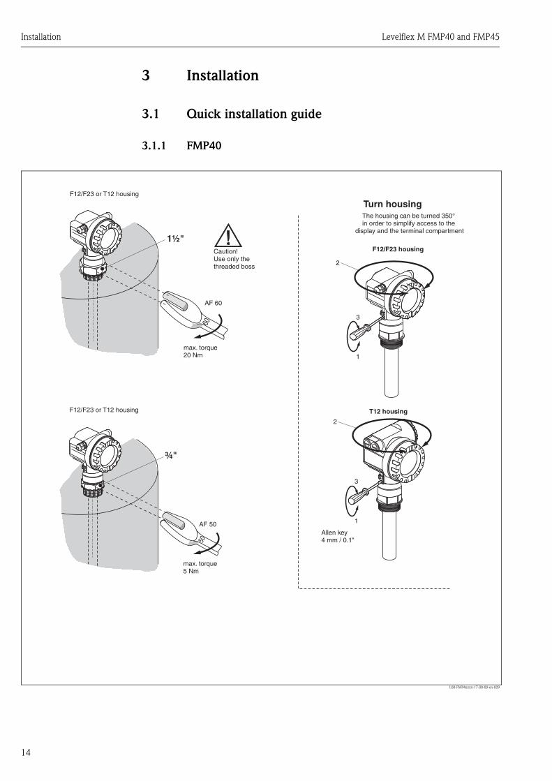
3 Installation
3.1 Quick installation guide
3.1.1 FMP40
L00-FMP4xxxx-17-00-00-en-029
3
1
3
1
2
2
6050
1½"
¾"
F12/F23 housing
T12 housing
Turn housingThe housing can be turned 350°in order to simplify access to the
display and the terminal compartment
Allen key4 mm / 0.1"
AF 60
AF 50
max. torque20 Nm
max. torque5 Nm
Caution!Use only thethreaded boss
F12/F23 or T12 housing
F12/F23 or T12 housing

Levelflex M FMP40 and FMP45 Installation
15
3.1.2 FMP45
L00-FMP45xxx-17-00-00-en-003
3.2 Incoming acceptance, transport, storage
3.2.1 Incoming acceptanceCheck the packing and contents for any signs of damage.Check the shipment, make sure nothing is missing and that the scope of supply matches your order.
3.2.2 Transport
" Caution! Follow the safety instructions and transport conditions for instruments of more than 18 kg. Do not lift the measuring instrument by its probe rod in order to transport it.
3.2.3 StoragePack the measuring instrument so that is protected against impacts for storage and transport. The original packing material provides the optimum protection for this.The permissible storage temperature is -40 °C…+80 °C.
3
1
2
60
1 "½ F12 housing
Turn housingThe housing can be turned 350°in order to simplify access to the
display and the terminal compartment
AF 60
max. torquesee table
Caution!Use only thethreaded boss ???
F12 or T12 housing
torqueProcess temperature
max. 280 °C 450 Nm
max. 400 °C 400 Nm

Installation Levelflex M FMP40 and FMP45
16
3.3 Installation conditions
3.3.1 Dimensions
Housing dimensions
Dimensions for the process connection and the probe type see Page 18.
L00-F12xxxx-06-00-00-en-001
L00-T12xxxx-06-00-00-en-001
L00-F23xxxx-06-00-00-en-001
ENDRESS+HAUSER
65 78max. 110
85
150
Ø 1
29
(Aluminium)F12 housing
ENDRESS+HAUSER
78
85
65
162
max. 100 94
Ø 1
29
(Aluminium)T12 housing
max. 94 104
Ø 1
29
150
40
(316L)F23 housing
Levelflex M FMP40 and FMP45 Installation
17
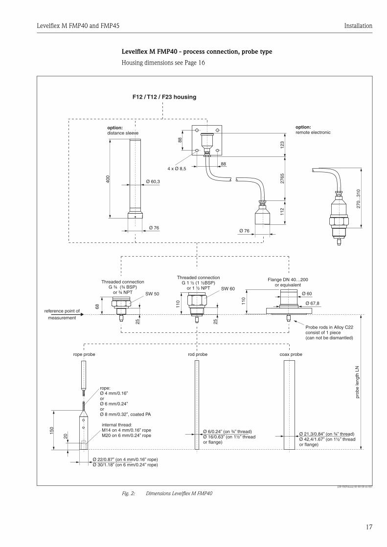
Levelflex M FMP40 - process connection, probe type
Housing dimensions see Page 16
L00-FMP4xxxx-06-00-00-en-007
Fig. 2: Dimensions Levelflex M FMP40
88
88
400
123
2765
112 27
0...3
10
Ø 76Ø 76
SW 50SW 60
4 x Ø 8,5
110 11
0
Ø 60
Ø 67,8
150
20
Ø 60,3
25 25
Threaded connectionG ¾ (¾ BSP)
or ¾ NPT
Threaded connectionG 1 ½ (1 ½BSP)
or 1 ½ NPT
Flange DN 40…200or equivalent
reference point of
measurement
option:distance sleeve
option:remote electronic
68
rope:Ø 4 mm/or
0.16”
Ø 6 mm/0.24”orØ 8 mm/0.32”, coated PA
rope probe rod probe coax probe
Ø 6/0.24” (on ¾” thread)Ø 16/0.63” (on 1½” threador flange)
Ø 21,3/0.84” (on ¾” thread)Ø 42,4/1.67” (on 1½” threador flange)
Ø 22/0.87” (on 4 mm/ rope)0.16”Ø 30/1.18” (on 6 mm/0.24” rope)
internal thread:M14 on 4 mm/0.16” ropeM20 on 6 mm/0.24” rope
prob
e le
ngth
LN
Probe rods in Alloy C22consist of 1 piece(can not be dismantled)
F12 / T12 / F23 housing

Installation Levelflex M FMP40 and FMP45
18
Levelflex M FMP45 - process connection, type of probe
Housing dimensions see Page 16.
L00-FMP45xxx-06-00-00-en-001
88
88
123
2765
112
Ø 76
4 x Ø 8,5
150
HT 400 °C XT 280 °C
Threaded connectionG 1 ½ (1 ½BSP)
or 1 ½ NPT
Threaded connectionG 1 ½ (1 ½BSP)
or 1 ½ NPT
Flange DN 50…100or equivalent
Flange DN 50…100or equivalent
reference point of
measurement
option:remote electronic
rope:Ø 4 mm/0.16”
rope probe rod probe coax probe
Ø 16/0.63” Ø 42,4/1.67”
Ø 22/0.87”
prob
e le
ngth
LN
F12 / T12 / F23 housing
SW 60 SW 60
262
159
159
338
2525
Ø 90Ø 90
Ø 90 Ø 90
Ø 60
Ø 60
Ø 60
Ø 60
132
23531
1
132

Levelflex M FMP40 and FMP45 Installation
19
3.4 Installation
3.4.1 General instructions for interface measurementFor the measurement of the interface level, the coaxial probe, the rod or rope probe may be used. However, rope and rod probes may be used in bypass resp. stilling well only. Rope probes should be used in exceptions only, e.g. if the measurement range extends for more than 4 meters or the available space above the tank is too limited to introduce rod probes.
The following constraints for the Levelflex Interface Version have to be considered:• The overall level has to be constant.• The dielectric constant of the upper prodcut level has to be smaller than 10.• The difference between the dielectric values of the two product levels should be 10 or bigger.• The minimum product level of each product is 100mm.
! Note! If one of these conditions is not met, the interface level measurement is not possible!
3.4.2 Installation• Coaxial probes may be mounted directly into the tank.• Rope and Rod probes have to be mounted into a bypass or stilling well• For the use of any probes into stilling wells it has to be made sure that the stilling well or bypass
is perforated in a way which allows the product level in the inner part of the stilling well to adjust to the outer level.
• The diameter of the stilling well / bypass should not exceed DN150 / 6” and not be smaller than DN 50 / 2”
For a bypass, the dimensions of the following diagram should be kept:
L00-FMP4xxxx-17-00-00-en-062
100 %
0 %
reco
mm
enda
tion
min
.20
0m
m/ 8
”re
com
men
datio
nm
in.
200
mm
/ 8”
50mm / 2” DN 150 mm / 6”< <

Installation Levelflex M FMP40 and FMP45
20
FMP45: Installing with heat insulation
• If process temperatures are high (≥ 200 °C), FMP45 must be included in normal tank insulation to prevent the electronics heating up as a result of heat radiation or convection.
• The insulation may not exceed beyond the points labelled "MAX" in the drawing.
Process connection with flange DN50...DN100
L00-FMP45xxx-17-00-00-en-001
Process connection with adapter G 1½" and 1½" NPT
L00-FMP45xxx-17-00-00-en-002
MAX
MAX
HT 400 °C
XT 280 °C
max. 400° C (752° F)max. 280° C (536° F)
tank insulation
tank insulation
high temperature version(type of probe B)
extended temperature version(type of probe A)
MAX
MAX
HT 400 °C
XT 280 °C
max. 400° C (752° F)max. 280° C (536° F)
tank insulation
tank insulation
high temperature version(type of probe B)
extended temperature version(type of probe A)

Levelflex M FMP40 and FMP45 Installation
21
3.4.3 Installation for difficult to access process connections
Installation with remote electronic
• Follow installation instructions on Page 19 ff.• Mount the housing on the wall or pipe (in vertical or horizontal position as required) as shown in
the diagram.
L00-FMP4xxxx-17-00-00-en-015
! Note! The connection tube cannot be disassembled at these points (1).
With remote electronics, for FMP40 temperatures up to 150 °C (302 °F) and for FMP45 temperatures up to 280 °C (536 °F) or 400 °C (752 °F) are permitted at the process connection depending on the instrument version. The ambient temperature for the connecting line (2) between the probe and electronics can be max. 105 °C. The version with remote electronics consists of the probe, a connecting tube and the housing. If they are ordered as a set, they are assembled on delivery.
150
ENDRESS+HAUSERLevelflex M
65 78
Ø 1
29
85
150
ENDRESS+HAUSERLevelflex M
65 78
Ø 1
29
85
52
52
150
max
.80
min
.30
96
94
94
88
88
123
2765
112
190
≥75
Ø 76
1
1
4 x Ø 8,5
1
2
pipe
wall
Note min.bend radius!

Installation Levelflex M FMP40 and FMP45
22
3.5 Turn housingAfter mounting, the housing can be turned 350° in order to simplify access to the display and the terminal compartment. Proceed as follows to turn the housing to the required position:
• Undo the fixing screws (1)• Turn the housing (2) in the required direction• Tighten up the fixing screws (1).
L00-FMP41Cxx-17-00-00-de-002
3.6 Post-installation checkAfter the measuring instrument has been installed, perform the following checks:
• Is the measuring instrument damaged (visual check)?• Does the measuring instrument correspond to the measuring point specifications such as process
temperature/pressure, ambient temperature, measuring range, etc.?• Are the measuring point number and labeling correct (visual check)?• Is the measuring instrument adequately protected against rain and direct sunlight (see
Page 56 ff.)?
90°90° 90°90°90°90°
11
2 2
F12/F23 housing T12 housing
allen key4 mm/0.1”

Levelflex M FMP40 and FMP45 Wiring
23
4 Wiring
4.1 Quick wiring guide
Wiring in F12/F23 housing
L00-FMP41Cxx-04-00-00-en-001
Made in GermanyD-79689 Maulburg
Dat./Insp.:
Order Code:
IP68 / NEMA 6PSer.-No.:
4-wire
ENDRESS+HAUSER
t >85°CTA > 70°C :
D01301-A
if modificationsee sep. labelX = Patents
LEVELFLEX-M
90 … 253 V AC 1VA10,5 … 32 V DC 1W16 … 3 V DC 0,8W
Profibus PAFoundation Fieldbus
LN= PN=
4 … 20 mA HART 2-wire
1 2 3 4
#
4
5
6
2
3
7
7
1
7
8-
-
"
5 6I+ I-
1 2L- L+
1 2L1/L+ N/L-
3 4I+ I-
ENDRESS+HAUSER
ENDRESS+HAUSER
Sealed terminalcompartment
Before connection please note the following:
The power supply must be identical to the data on thenameplate (1).
Switch off power supply before connecting up the device.
Connect Equipotential bonding to transmitterground terminal (7) before connecting up the device.
Tighten the locking screw (8):It forms the connection between the probe and the housingground potential.
When you use the measuring system in hazardous areas, make sure you comply withnational standards and the specifications in the safety instructions (XA’s).Make sure you use the specific cable gland.
On devices supplied with a certificate, the explosion protectionis designed as follows:
Housing F12/F23 - EEx ia:Power supply must be intrinsically safe (not for dust-Ex).
The electronics and the current output are galvanicallyseparated from the probe circuit.
Connect up the Levelflex M as follows:
Unscrew housing cover (2).
Remove any display (3) if fitted.
Remove cover plate from terminal compartment (4).
Pull out terminal module slightly using "pulling loop" (only 2-wire).
Only ground screening of the line (7) on sensor side.
Make connection (see pin assignment).
Re-insert terminal module.
Tighten cable gland (6). Max. torque 10...12 Nm!
Tighten screws on cover plate (4).
Insert display if fitted.
Screw on housing cover (2).(on dust-Ex torque 40 Nm).
Switch on power supply.
≈
Insert cable (5) through gland (6).A standard installation cable is sufficient if only the analogue signal isused. Use a screened cable when working with a superimposedcommunications signal (HART).
Unplug display connector!
Caution!
Note!plantground
test sockets(output current)
power powerdisplay unit,recorder, PCS
2-wire-version 4-wire-version
If 4-wire for dust-Ex-applications is used,the current output is .intrinsically save
AC / DCDC
plantground
0...20mA
Wiring Levelflex M FMP40 and FMP45
24
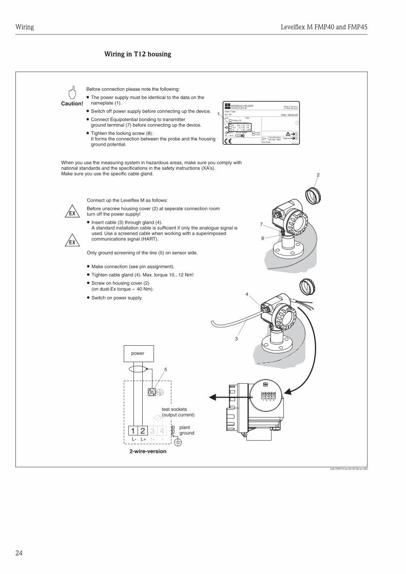
Wiring in T12 housing
L00-FMP41Cxx-04-00-00-en-002
Made in GermanyD-79689 Maulburg
Dat./Insp.:
Order Code:
IP68 / NEMA 6PSer.-No.:
4-wire
ENDRESS+HAUSER
t >85°CTA > 70°C :
D01301-A
if modificationsee sep. labelX = Patents
LEVELFLEX-M
90 … 253 V AC 1VA10,5 … 32 V DC 1W16 … 3 V DC 0,8W
Profibus PAFoundation Fieldbus
LN= PN=
4 … 20 mA HART 2-wire
2
-
-
1 2 3 4
4
3
1
5
1 2L- L+
7
8
3 4I+ I-
Caution!"
Before connection please note the following:
The power supply must be identical to the data on thenameplate (1).
Switch off power supply before connecting up the device.
Connect Equipotential bonding to transmitterground terminal (7) before connecting up the device.
Tighten the locking screw (8):It forms the connection between the probe and the housingground potential.
When you use the measuring system in hazardous areas, make sure you comply withnational standards and the specifications in the safety instructions (XA’s).Make sure you use the specific cable gland.
Connect up the Levelflex M as follows:
Before unscrew housing cover (2) at seperate connection roomturn off the power supply!
Insert cable (3) through gland (4).
Only ground screening of the line (5) on sensor side.
Make connection (see pin assignment).
Tighten cable gland (4). Max. torque 10...12 Nm!
Screw on housing cover (2)(on dust-Ex torque 40 Nm).
Switch on power supply.
≈
A standard installation cable is sufficient if only the analogue signal isused. Use a screened cable when working with a superimposedcommunications signal (HART).
plantground
test sockets(output current)
power
2-wire-version

Levelflex M FMP40 and FMP45 Wiring
25
4.2 Connecting the measuring unit
Terminal compartment
Three housings are available:• Aluminium housing F12 with additionally sealed terminal compartment for:
– standard,– EEx ia.
• Aluminium housing T12 with separate terminal compartment for:– standard,– EEx e,– EEx d– EEX ia (with overvoltage protection).
• Stainless steel 316L housing F23 for:– standard,– EEx ia.
After mounting, the housing can be turned 350° in order to simplify access to the display and the terminal compartment.
L00-FMR2xxxx-04-00-00-en-019
The instrument data are given on the nameplate together with important information regarding the analog output and voltage supply. Housing orientation regarding the wiring see "Turn housing" on Page 22.
Load HART
Minimum load for Hart communication: 250 Ω
Cable entry
Cable gland: M20x1.5Cable entry: G ½ or ½ NPT
Supply voltage
HART, 2-wire
The following values are the voltages across the terminals directly at the instrument:
1 12 23 34 41 2 3 4
sealed terminalcompartment
F12 housing F23 housingT12 housing

Wiring Levelflex M FMP40 and FMP45
26
HART residual ripple, 2-wire: Uss ≤ 200 mV
HART, 4-wire active
Power consumption
min. 60 mW, max. 900 mW
Current consumption
Overvoltage protection
If there is the risk of differences in potential forming when installing the Levelflex M to measure the level of flammable liquids, the device can be fitted with a T12 housing and integrated overvoltage protection (600 V gas tube surge arrester), see Ordering structure on Page 6. This overvoltage protection meets the requirements of DIN EN 60079-14, test standard 60060-1, and also protects the device (10 kA, impulse 8/20 µs).
Communication Currentconsumption
Terminal voltage
minimal maximal
HARTstandard
4 mA 16 V 36 V
20 mA 7.5 V 36 V
EEx ia4 mA 16 V 30 V
20 mA 7.5 V 30 V
EEx emEEx d
4 mA 16 V 30 V
20 mA 11 V 30 V
Fixed current, adjustable e.g. for solar power operation (measured value transferred at HART)
standard 11 mA 10 V 36 V
EEx ia 11 mA 10 V 30 V
Fixed current for HART Multidrop mode
standard 4 mA1)
1) Start up current 11 mA.
16 V 36 V
EEx ia 4 mA1) 16 V 30 V
Version Voltage Max. load
DC 10.5...32 V 600 Ω
AC 85...250 V 600 Ω
Communication Current consumption
Current consumption
Power consumption
HART, 2-wire 3.6…22 mA —
HART, 4-wire (90...250 VAC) 2.4...22 mA ~ 3...6 mA / ~ 3.5 VA
HART, 4-wire (10,5...32 VDC) 2.4...22 mA ~ 100 mA / ~ 1 W
PROFIBUS-PA max. 11 mA —
Foundation Fieldbus (FF) max. 15 mA —

Levelflex M FMP40 and FMP45 Wiring
27
4.2.1 HART connection with E+H RMA 422 / RN 221 N
L00-FMP4xxxx-04-00-00-yy-001
4.2.2 HART connection with other supplies
L00-FMP4xxxx-04-00-00-en-002
" Caution! If the HART communication resistor is not built into the supply unit and the HART interface is to be used, it is necessary to insert a communication resistor of 250 Ω into the 2-wire line.
4...20 mA
1 2 3 4
ENDRESS + HAUSERRMA 422
CommuboxFXA191
RMA422RN221N
- FieldCare
1 2 3 4- FieldCare
CommuboxFXA191
³ W250
PLC
DC power supplyunit
or
4...20 mA

Wiring Levelflex M FMP40 and FMP45
28
4.3 Recommended connection
4.3.1 Equipotential bondingConnect the Equipotential bonding to the external ground terminal (1) of the transmitter.
L00-FMP41Cxx-17-00-00-en-003
4.3.2 Wiring screened cable
" Caution! In Ex applications, the instrument must only be grounded on the sensor side. Further safety instructions are given in the separate documentation for applications in explosion hazardous areas.
4.4 Degree of protection• housing: IP 68, NEMA 6P (open housing: IP20, NEMA 1)• probe: IP 68 (NEMA 6P)
4.5 Post-connection checkAfter wiring the measuring instrument, perform the following checks:• Is the terminal allocation correct (see Page 23 ff. and Page 24)?• Is the cable gland tight?• Is the housing cover screwed tight?• If auxiliary power is available:
Is the instrument ready for operation and is the liquid crystal display visible?
11
F12/F23 housing T12 housing
Levelflex M FMP40 and FMP45 Operation
29
5 Operation
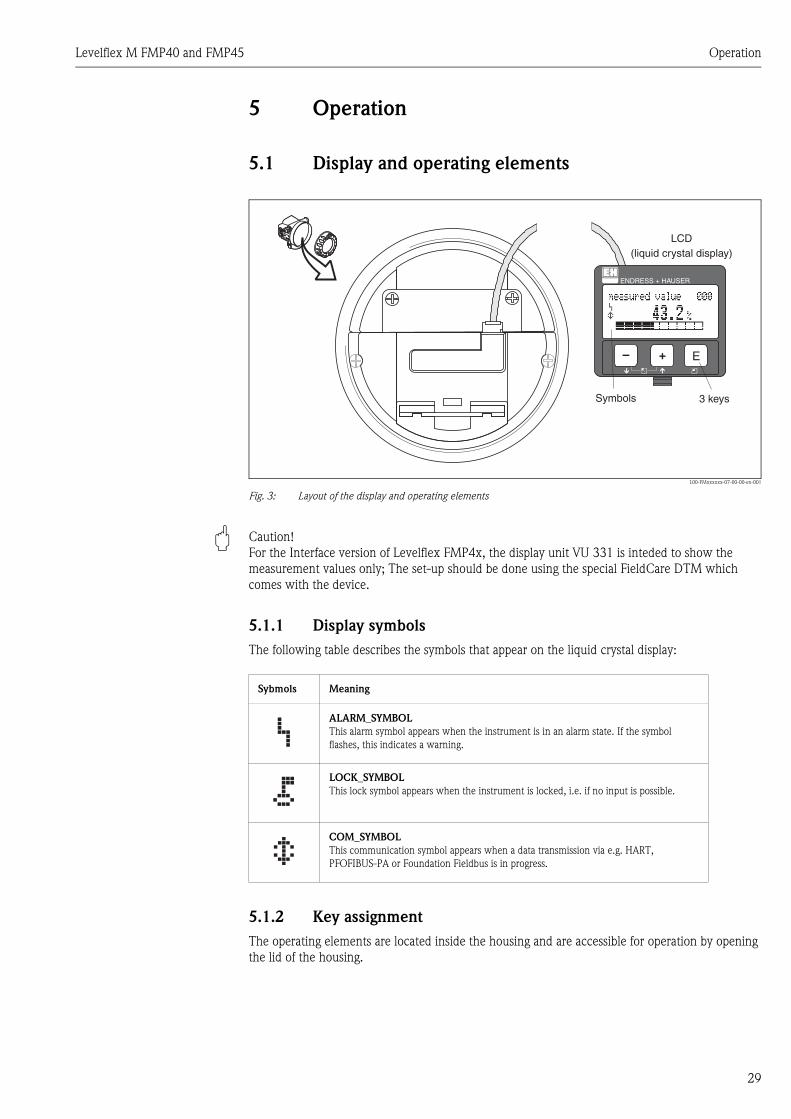
5.1 Display and operating elements
L00-FMxxxxxx-07-00-00-en-001
Fig. 3: Layout of the display and operating elements
" Caution! For the Interface version of Levelflex FMP4x, the display unit VU 331 is inteded to show the measurement values only; The set-up should be done using the special FieldCare DTM which comes with the device.
5.1.1 Display symbolsThe following table describes the symbols that appear on the liquid crystal display:
5.1.2 Key assignmentThe operating elements are located inside the housing and are accessible for operation by opening the lid of the housing.
ENDRESS + HAUSER
E+–
ENDRESS+HAUSER
MICROPILOT II
ENDRESS+HAUSER
MICROPILOT II
IP 65IP 65
Order Code:Ser.-No.:
Order Code:Ser.-No.:
MessbereichMeasuring range
MessbereichMeasuring rangeU 16...36 V DC
4...20 mA
U 16...36 V DC4...20 mA
max. 20 m
max. 20 m
Made in
Germ
any
M
aulb
urg
Made in
Germ
any
M
aulb
urg
T>70°C :
A
t >85°C
T>70°C :
A
t >85°C LCD(liquid crystal display)
Symbols 3 keys
Sybmols Meaning
ALARM_SYMBOLThis alarm symbol appears when the instrument is in an alarm state. If the symbol flashes, this indicates a warning.
LOCK_SYMBOLThis lock symbol appears when the instrument is locked, i.e. if no input is possible.
COM_SYMBOLThis communication symbol appears when a data transmission via e.g. HART, PFOFIBUS-PA or Foundation Fieldbus is in progress.

Operation Levelflex M FMP40 and FMP45
30
Function of the keys
" Caution! For the Interface version of Levelflex FMP4x, the display unit VU 331 is inteded to show the measurement values only; The set-up should be done using the special FieldCare DTM which comes with the device.
Key(s) Meaning
O or V Navigate upwards in the selection listEdit numeric value within a function
S or W Navigate downwards in the selection listEdit numeric value within a function
X or Z Navigate to the left within a function group
For M Navigate to the right within a function group, confirmation.
O and For
S and F
Contrast settings of the LCD
O and S and F
Hardware lock / unlockAfter a hardware lock, an operation of the instrument via display orcommunication is not possible!The hardware can only be unlocked via the display. An unlock parameter must be entered to do so.
Levelflex M FMP40 and FMP45 Operation
31
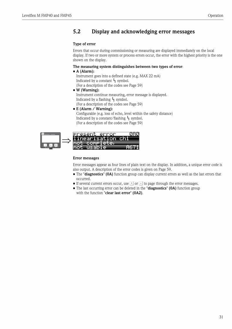
5.2 Display and acknowledging error messages
Type of error
Errors that occur during commissioning or measuring are displayed immediately on the local display. If two or more system or process errors occur, the error with the highest priority is the one shown on the display.
The measuring system distinguishes between two types of error:• A (Alarm):
Instrument goes into a defined state (e.g. MAX 22 mA)Indicated by a constant symbol.(For a description of the codes see Page 59)
• W (Warning):Instrument continue measuring, error message is displayed.Indicated by a flashing symbol.(For a description of the codes see Page 59)
• E (Alarm / Warning): Configurable (e.g. loss of echo, level within the safety distance)Indicated by a constant/flashing symbol.(For a description of the codes see Page 59)
Error messages
Error messages appear as four lines of plain text on the display. In addition, a unique error code is also output. A description of the error codes is given on Page 59.• The "diagnostics" (0A) function group can display current errors as well as the last errors that
occurred.• If several current errors occur, use O or S to page through the error messages.• The last occurring error can be deleted in the "diagnostics" (0A) function group
with the function "clear last error" (0A2).
⇒ENDRESS + HAUSER
E+–
Commissioning Levelflex M FMP40 and FMP45
32
6 Commissioning
6.1 Function checkMake sure that all final checks have been completed before you start up your measuring point:• Checklist “Post-installation check” (see Page 22 ff.).• Checklist “Post-connection check” (see Page 22 ff.).
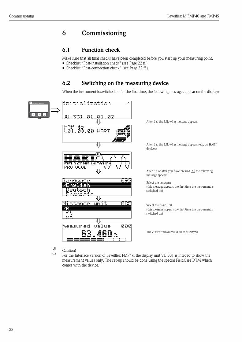
6.2 Switching on the measuring deviceWhen the instrument is switched on for the first time, the following messages appear on the display:
" Caution! For the Interface version of Levelflex FMP4x, the display unit VU 331 is inteded to show the measurement values only; The set-up should be done using the special FieldCare DTM which comes with the device.
⇒⇓ After 5 s, the following message appears
⇓ After 5 s, the following message appears (e.g. on HART devices)
⇓ After 5 s or after you have pressed F the following message appears
Select the language(this message appears the first time the instrument is switched on)
⇓Select the basic unit(this message appears the first time the instrument is switched on)
⇓The current measured value is displayed
ENDRESS + HAUSER
E+–

Levelflex M FMP40 and FMP45 Commissioning
33
6.3 Basic SetupThe Basic Setup of the device has to be performed with a special FieldCare DTM which is delivered with the device. The setup is not inteded to be made via the display VU 331 or via any other digital communication!
In order to perform the basic calibration via FieldCare, please proceed as follows:• connect the FXA191 (HART Commubox) with the device • start FieldCare and define a new project.• Add a HART Comm DTM to the project.• Add the FMP4x Interface HART DTM.• Extablish an on-line communication to the device by pressing .• Start the parametrization by opening th "on-line parametrization".
L00-FMP4xxxx-19-00-00-de-002
On the screen, the following picture will appear:
L00-FMP4xxxx-19-00-00-de-004
Please use the flash buttoms to go through the basic calibration step by step.

Commissioning Levelflex M FMP40 and FMP45
34
Basic Setup step 1/4:• The TAG of the measurement point can be edited.• Additional information are displayed:
protocol and SW numberdevice nameorder code
L00-FMP4xxxx-19-00-00-de-006
! Note! Each changed parameter has to be entered / confirmed by the Return key.
Basic Setup step 2/4:• Enter the application parameters:
– Dielectric const.– Dist. total level
l00-L00-FMP4xxxx-19-00-00-de-007

Levelflex M FMP40 and FMP45 Commissioning
35
Function "Dielectric. const."By this function the medium property of the upper product layer is defined. The dielectric value can be defined also by clicking the tank smbol and by this opening the table book of dielectric values. By entering the dielectic value, the threshold (noise level elimination) of the device is configured. If it is necessary to adjust this threshold manually, this can be done in step 4.
l00-L00-FMP4xxxx-19-00-00-de-008
! Note! The table value of the dielectic constant may be different from the real product dielectric value.
Function "Dist. total level"By this function, the distance to the overall level is defined. It is used to compensate the gas layer above the product.
! Note! After entering the function “Dist. total level”, the parameter “upper blocking dist.” is adjusted to the same value!

Commissioning Levelflex M FMP40 and FMP45
36
Basic Setup step 3/4:• Enter the length calibration:
– Function "probe length"
l00-fmp4xxxx-20-00-00-de-004
Function "probe length"By this function it is defined if the probe length has been changed after factory calibration. Any adjustment is necessary only if the probe length has been changed!
Selection:• Not changed • Changed
L00-FMP4xxxx-19-00-00-de-009
In case the function "probe length " "changed" has been selected, in the following steps the new, actual probe length can be entered.
Levelflex M FMP40 and FMP45 Commissioning
37
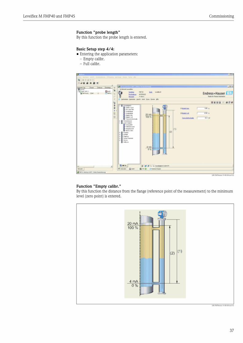
Function "probe length"By this function the probe length is entered.
Basic Setup step 4/4:• Entering the application parameters:
– Empty calibr.– Full calibr.
L00-FMP4xxxx-19-00-00-de-012
Function "Empty calibr." By this function the distance from the flange (reference point of the measurement) to the minimum level (zero point) is entered.
L00-FMP4xxxx-19-00-00-de-013

Commissioning Levelflex M FMP40 and FMP45
38
Function "Full calibr." By this function the distance from the minimum level to the maximum overall level (Span) is entered.The 100% Point should not be higher than the overall (total) level!
L00-FMP4xxxx-19-00-00-de-013
" Achtung!The usable measurement range is situated between the overall level and the probe length. Especially for products / media of the upper layer with a dielectric value bigger than 4, the measurement range can be diminished by adjusting the upper blocking distance.More information about this topic please refer to function “upper blocking dist.” see page 47.
Levelflex M FMP40 and FMP45 7 Description of Instrument Functions
7 Description of Instrument Functions
7.1 Function group "basic setup"
7.1.1 Function "measured value"This function displays the current measured value in the selected unit. The number of places after decimal point can be selected in the "no.of decimals" function.
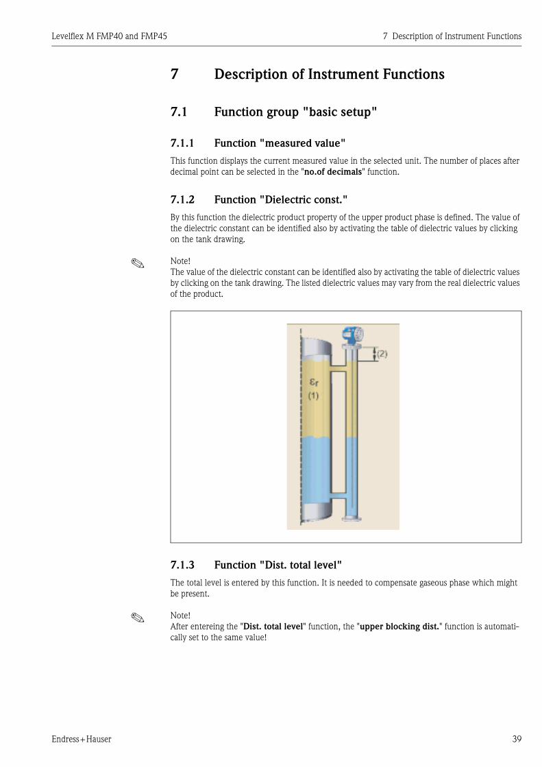
7.1.2 Function "Dielectric const."By this function the dielectric product property of the upper product phase is defined. The value of the dielectric constant can be identified also by activating the table of dielectric values by clicking on the tank drawing.
! Note!The value of the dielectric constant can be identified also by activating the table of dielectric values by clicking on the tank drawing. The listed dielectric values may vary from the real dielectric values of the product.
7.1.3 Function "Dist. total level"The total level is entered by this function. It is needed to compensate gaseous phase which might be present.
! Note!After entereing the "Dist. total level" function, the "upper blocking dist." function is automati-cally set to the same value!
Endress+Hauser 39

7 Description of Instrument Functions Levelflex M FMP40 and FMP45
7.1.4 Function "empty calibr."This function is used to enter the distance from the flange (reference point of the measurement) to the minimum level (=zero).
7.1.5 Function "full calibr."This function is used to enter the distance from the minimum level to the maximum level (=span).The 100% point should not be defined at a higher level than the overall level
40 Endress+Hauser

Levelflex M FMP40 and FMP45 7 Description of Instrument Functions
! Note!The usable measurement range extends between the overall level and the probe length.For media of the upper product phase with a dielectric value > 4, the measurement range may have to be restricted by increasing the upper blocking distance. The upper blocking distance is used to eliminate the overall level echo.Further Informations to the "blocking distance" see function "upper blocking dist." on page 47.
7.2 Function group "safety settings"
7.2.1 Function "output on alarm"This function is used to select the reaction of output on an alarm.
Selection:• MIN (<= 3.6mA)• MAX (22mA)• hold• user specific
MIN (<= 3.6mA)
If the instrument is in alarm state, the output changes as follows:• HART: MIN-Alarm 3.6 mA
MAX 110% 22mA
Endress+Hauser 41

7 Description of Instrument Functions Levelflex M FMP40 and FMP45
If the instrument is in alarm state, the output changes as follows:• HART: MAX-Alarm 22 mA
hold
If the instrument is in alarm state, the last measured value is held.
user specific
If the instrument is in alarm state, the output is set to the value configured in "output on alarm" (x mA).
" Caution!This selection is available for HART devices only!
7.2.2 Function "output on alarm", HART onlyOn alarm, the output current is in mA. This function is active when you selected "user specific" in the "output on alarm" function.
" Caution!This function is available for HART devices only!
42 Endress+Hauser
Levelflex M FMP40 and FMP45 7 Description of Instrument Functions
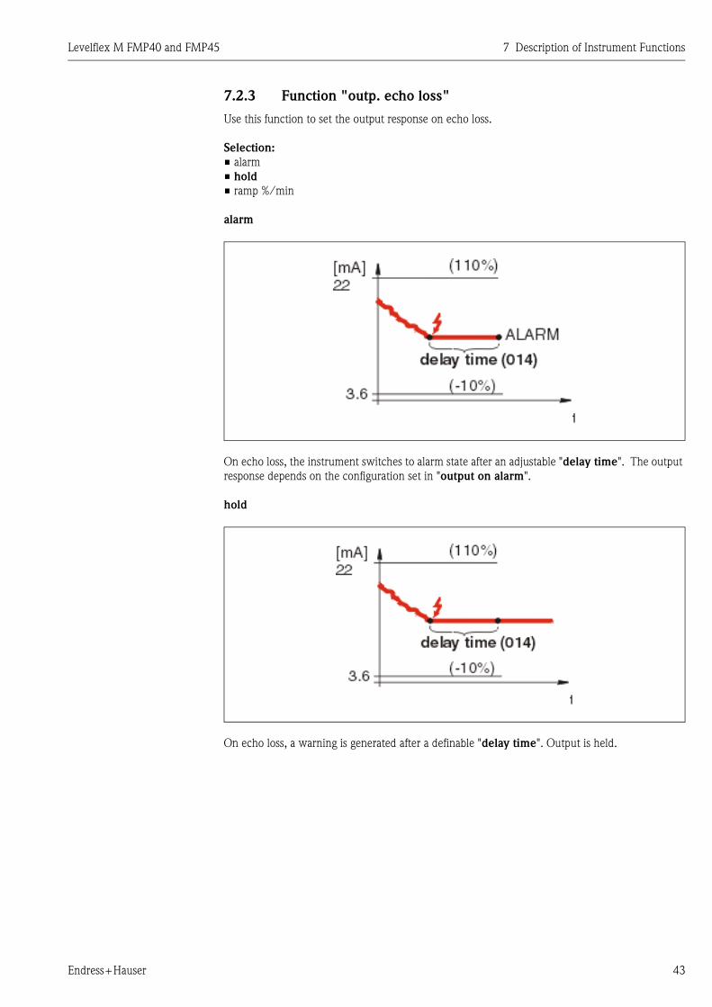
7.2.3 Function "outp. echo loss"Use this function to set the output response on echo loss.
Selection:• alarm• hold• ramp %/min
alarm
On echo loss, the instrument switches to alarm state after an adjustable "delay time". The output response depends on the configuration set in "output on alarm".
hold
On echo loss, a warning is generated after a definable "delay time". Output is held.
Endress+Hauser 43

7 Description of Instrument Functions Levelflex M FMP40 and FMP45
ramp %/min
On echo loss, a warning is generated after a definable "delay time". The output is changed towards 0% or 100% depending on the slope defined in "ramp %span/min".
7.2.4 Function "ramp %span/min"Ramp slope which defines the output value on echo loss. This value is used if "ramp %span/min" is selected in "outp. echo loss". The slope is given in % of the measuring range per minute.
7.2.5 Function "delay time"Use this function to enter the delay time (Default = 30 s) after which a warning is generated on echo loss, or after which the instrument switches to alarm state.
7.2.6 Function "safety distance"A configurable safety distance is placed before the "blocking dist.". This distance warns you that any further level increase would make the measurement invalid.
Enter the size of the safety distance here. The default value is: 0.1 m.
44 Endress+Hauser

Levelflex M FMP40 and FMP45 7 Description of Instrument Functions
7.2.7 Function "in safety dist."This function defines the response when the level enters the safety distance .
Selection:• alarm• warning
alarm
Instrument enters the defined alarm state ("output on alarm"). The alarm message E651 -"level in safety distance - risk of overspill" is displayed.If the level drops out of the safety distance, the alarm warning disappears and the instrument starts to measure again.
warning
Instrument displays a warning E651 - "level in safety distance - risk of overspill", but conti-nues to measure. If the level leaves the safety distance, the warning disappears.
Endress+Hauser 45

7 Description of Instrument Functions Levelflex M FMP40 and FMP45
7.3 Function group "length adjustment"
7.3.1 Function "probe length"Use this function to select whether the probe length was changed after factory calibration. Only then is it necessary to enter or correct the probe length.
Selection:• modified• not modified
! Note!If "modified" was selected in the "probe length" function, the probe length is defined in the next step.
7.3.2 Function "probe length"Use this function to enter the probe length.
7.4 Function group "extended calibr."
7.4.1 Function "echo quality"
The echo quality is the benchmark for measurement reliability. It describes the amount of reflected energy and depends primarily on the following conditions:• Dielectric constant of the medium• probe type• Distance between sensor and product
Low values increase the probability that the echo is lost through a change in measurement conditi-ons, e.g. emulsion or high dampening of the upper product phase.
7.4.2 Function "offset"This function corrects the measured level by a constant value. The entered value is added to the measured level.
46 Endress+Hauser

Levelflex M FMP40 and FMP45 7 Description of Instrument Functions
7.4.3 Function "output damping"Influences the time an output requires to react to a sudden level jump (63% of steady state). A high value attenuates, for example, the influences of rapid changes on the measured variable.
User input:0...255 s
The default value depends on the selected application parameter "process cond.".
7.4.4 Function "upper blocking dist."In case of strong reflections of the upper (overall) level, the echo signal of the overall level has to be eliminated by the blocking distance. It is advised to enter the “distance overall level” + 100mm.
! Note!The available measuring range is decreased by the value entered.
7.5 Function group "output"
7.5.1 Function "commun. address", HART onlyEnter the communication address for the instrument with this function.• Standard: 0• Multidrop: 1-15In multidrop mode, the standard output current is 4 mA. This can be changed in the "fixed cur. value" function.
" Caution!This function is available for HART devices only!
7.5.2 Function "no. of preambels", HART onlyEnter the number of preambles for the HART protocol with this function.An increase in the value is advisable for "bad" lines with communications problems.
" Caution!This user input is available for HART devices only!
Endress+Hauser 47

7 Description of Instrument Functions Levelflex M FMP40 and FMP45
7.5.3 Function "low output limit", HART onlyThe output of negative level values can be suppressed with this function.
Selection:• off minimum output -10% (3.8 mA for HART)• on minimum output 0% (4 mA for HART)
" Caution!This user input is available for HART devices only!
7.5.4 Function "curr. output mode", HART onlyUse this function to specify the current output mode for HART devices.
Selection:• standard• curr. turn down• fixed current
standardThis selection displays the complete measuring range (0...100%) across the full current interval (4...20 mA).
curr. turn downThis selection only displays a part of the measuring range across the full current interval (4...20 mA). This range is specified using the "4mA value" and "20mA Value" functions.
fixed currentSelecting this outputs a fixed current. The measured value is only transmitted using the HART sig-nal. The current output value is set using the "fixed cur. value" function.
" Caution!This selection is available for HART devices only!
48 Endress+Hauser
Levelflex M FMP40 and FMP45 7 Description of Instrument Functions
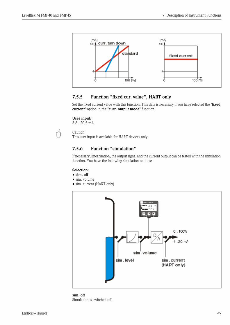
7.5.5 Function "fixed cur. value", HART onlySet the fixed current value with this function. This data is necessary if you have selected the "fixed current" option in the "curr. output mode" function.
User input:3,8...20,5 mA
" Caution!This user input is available for HART devices only!
7.5.6 Function "simulation"If necessary, linearisation, the output signal and the current output can be tested with the simulation function. You have the following simulation options:
Selection:• sim. off• sim. volume• sim. current (HART only)
sim. offSimulation is switched off.
Endress+Hauser 49
7 Description of Instrument Functions Levelflex M FMP40 and FMP45
sim. levelEnter the level value in "simulation value".The functions• measured value• measured level• output current" - only with HART instruments!follow the entered values.
sim. volumeEnter the volume value in "simulation value".The functions• measured value• output current" - only with HART instruments!follow the entered values.
sim. current (HART only)Enter the current value in "simulation value".The function• output current" - only with HART instruments!follows the entered values.
7.5.7 Function "simulation value"
7.5.8 Function "output current", HART onlyDisplays the output current in mA.
" Caution!This function is available for HART devices only!
7.5.9 Function "4mA value", HART onlyIn this function, enter the level (or volume, weight) at which the output current should be 4 mA. This entry is only required if you selected the "current turn down" option in the "curr. output mode" function.
7.5.10 Function "20mA value", HART onlyIn this function, enter the level (or volume, weight) at which the output current should be 20 mA. This entry is only required if you have selected the"current turn down" option in the "curr. output mode" function.
7.6 Function group "display"
7.6.1 Function "language"Selects the display language.
Selection:• English• Deutsch• Français• Español• Italiano• Nederlands• Katakana (japanese)
50 Endress+Hauser

Levelflex M FMP40 and FMP45 7 Description of Instrument Functions
DependenceAll texts are changed.
" Caution!This function is not visualised in Commuwin II!
7.6.2 Function "back to home"If no entry is made using the display during the specified time period, the display returns to the measured value display.9999 s means that there is no return.
User input:3...9999 s
7.6.3 Function "format display"Selects the display format.
Selection:• decimal• ft-in-1/16"
decimalThe measured value is given in decimal form in the display (e.g. 10.70%).
ft-in-1/16"The measured value is given in the display in this format (e.g 5'05-14/16").This option is only possible for "distance unit" - "ft" and "in"!
7.6.4 Function "no.of decimals"
Selection:• x• x.x• x.xx• x.xxx
7.6.5 Function "sep. character"
Selection:• .• ,
.The decimal place is separated by a point.
,The decimal place is separated by a comma.
7.6.6 Function "display test"All display pixels are switched on. If the whole LCD is dark, it is working correctly.
Endress+Hauser 51

7 Description of Instrument Functions Levelflex M FMP40 and FMP45
7.7 Function group "diagnostics"
In the "diagnostics" function group, you can display and confirm error messages.
Type of errorErrors that occur during commissioning or measuring are displayed immediately on the local dis-play. If two or more system or process errors occur, the error with the highest priority is the one shown on the display.The measuring system distinguishes between two types of error:• A (Alarm):
Instrument goes into a defined state (e.g. MAX)Indicated by a constant symbol.(For a description of the codes see system error messages)
• W (Warning):Instrument continue measuring, error message is displayed.Indicated by a flashing symbol.(For a description of the codes, see system error messages)
• E (Alarm / Warning):Configurable (e.g. loss of echo, level within the safety distance)Indicated by a constant/flashing symbol.(For a description of the codes, see system error messages)
Error messagesError messages appear as four lines of plain text on the display. In addition, a unique error code is also output. A description of the error codes is given by system error messages.• The "diagnostics" function group can display current errors as well as the last errors that occur-
red.• If several current errors occur, use O or S to page through the error messages.The last occurring error can be deleted in the "diagnostics" function group with the function "clear last error".
7.7.1 Function "present error"The present error is shown using this function.
7.7.2 Function "previous error"The last error presented is shown with this function.
7.7.3 Function "clear last error"
Selection:• keep• erase
7.7.4 Function "reset"
" Caution!Generally, no reset is necessary.
52 Endress+Hauser
Levelflex M FMP40 and FMP45 7 Description of Instrument Functions
7.7.5 Function "unlock parameter"Set-up can be locked and unlocked with this function. Levelflex M for interface measurements is delivered in locked status (access code = 99). The access code has to be entered before the device commissioning. It is advised to lock the device again after installation and commissioning.
7.7.6 Locking of the configuration modeThe Levelflex can be protected in two ways against unauthorised changing of instrument data, numerical values or factory settings:
"unlock parameter":A value <> 100 for HART (e.g. 99) must be entered in "unlock parameter" in the "diagnostics" function group. The lock is shown on the display by the symbol and can be released again either via the display or by communication.
7.7.7 Unlocking of configuration modeIf an attempt is made to change parameters when the instrument is locked, the user is automatically requested to unlock the instrument:
"unlock parameter":By entering the unlock parameter (on the display or via communication)
100 = for HART devices
the Levelflex is released for operation.
" Caution!Changing certain parameters such as all sensor characteristics, for example, influences numerous functions of the entire measuring system, particularly measuring accuracy. There is no need to change these parameters under normal circumstances and consequently, they are protected by a special code known only to the E+H service organization. Please contact Endress+Hauser if you have any questions.
7.7.8 Function "measured dist."Display of measured distance in the selected "distance unit".
7.7.9 Function "measured level"Display of measured level in the selected "distance unit".
7.7.10 Function "application par."If, for example, the "output damping" is changed, the "application par." shows "modified".
Selection:• not modified• modified
Endress+Hauser 53
7 Description of Instrument Functions Levelflex M FMP40 and FMP45
7.8 Function group "system parameters"
7.8.1 Function "tag no."You can define the tag number with this function.
User input:• 16 alphanumeric characters for HART instruments (8 using the HART universal command)
7.8.2 Function "protocol+sw-no."This function shows the protocol and the hardware and software version: Vxx.yy.zz.prot.
Display:xx: hw-versionyy: sw-versionzz: sw-revisionprot: protocoll type (e.g. HART)
7.8.3 Function "serial no."This function displays the instrument serial number.
7.8.4 Function "distance unit"You can select the basic distance unit with this function.
Selection:• m• ft• mm• inch
Dependencem, mm: "format display" can only be "decimal".
The units are changed for the following parameters:• empty calibr.• full calibr.• safety distance• offset• measured dist.• measured level
7.8.5 Function "download mode"
! Note!The parameter up- / download are not possible with the Levelflex M interface version.
7.9 Function group "service"
Parameters in the function group service are for use of the E+H Service only!
7.9.1 System error messagesSee Chapter 10.2.
54 Endress+Hauser

Levelflex M FMP40 and FMP45 Maintenance
55
8 MaintenanceThe Levelflex M measuring instrument requires no special maintenance.
Exterior cleaning
When cleaning the Levelflex M, always use cleaning agents that do not attack the surface of the housing and the seals.
Repairs
The Endress+Hauser repair concept assumes that the measuring devices have a modular design and that customers are able to undertake repairs themselves. Spare parts are contained in suitable kits. They contain the related replacement instructions. All the spare parts kits which you can order from Endress+Hauser for repairs to the Levelflex M are listed with their order numbers on Page 60 ff.*. * Excepted from this is the exchange of an electronics according to MVTFN0341. Please contact Endress+Hauser Service for further information on service and spare parts.
Repairs to Ex-approved devices
When carrying out repairs to Ex-approved devices, please note the following:• Repairs to Ex-approved devices may only be carried out by trained personnel or by
Endress+Hauser Service.• Comply with the prevailing standards, national Ex-area regulations, safety instructions (XA) and
certificates.• Only use original spare parts from Endress+Hauser.• When ordering a spare part, please note the device designation on the nameplate. Only replace
parts with identical parts.• Carry out repairs according to the instructions. On completion of repairs, carry our the specified
routine test on the device.• Only Endress+Hauser Service may convert a certified device into a different certified variant.• Document all repair work and conversions.
Replacement electronics module
After a complete electronic module has been replaced, the parameters can be downloaded into the instrument not again via the communication interface. After a probe or electronic has been replaced, a new basic setup must be performed by the Endress+Hauser service.

Accessories Levelflex M FMP40 and FMP45
56
9 AccessoriesVarious accessories, which can be ordered separately from Endress+Hauser, are available for the Levelflex M.
Weather protection cover
A Weather protection cover made of stainless steel is available for outdoor mounting (order code: 543199-0001). The shipment includes the protective cover and tension clamp.
L00-FMR2xxxx-00-00-06-en-001
Commubox FXA 191 HART
For intrinsically safe communication via the RS 232C interface using FieldCare.
ENDRESS+HAUSER
MICROPILOT II
ENDRESS+HAUSER
MICROPILOT II
IP 65
Order Code:Ser.-No.:
Order Code:Ser.-No.:
MessbereichMeasuring range
MessbereichMeasuring rangeU 16...36 V DC
4...20 mA
U 16...36 V DC4...20 mA
max. 20 m
max. 20 m
Made in
Germ
any
Maulb
urg
Made in
Germ
any
Maulb
urg
T>70°C :
A
t >85°C
T>70°C :
A
t >85°C
F12 / F23 / T12 housing

Levelflex M FMP40 and FMP45 Accessories
57
Remote display FHX40
Dimensions
L00-FMxxxxxx-00-00-06-en-003
Technical data (cable and housing) and product structure:
ENDRESS+HAUSER
ENDRESS+HAUSER
IP 65
Order Code:Ser.-No.:
Order Code:Ser.-No.:
MessbereichMeasuring range
MessbereichMeasuring range
U 16...36 V DC4...20 mA
U 16...36 V DC4...20 mA
max. 20 m
max. 20 m
Mad
e in
Ger
man
y
M
aulb
urg
Mad
e in
Ger
man
y
M
aulb
urg
T>70°C :
A
t >85°C
T>70°C :
A
t >85°C
82
6,310
6
122
120
max. 80min. 30
96
88
160
8,5
118
180Micropilot M
Levelflex MProsonic M
Separate housingFHX 40 (IP 65)
Cable
122
150
80
Wall-mounting(without mounting bracket)
Pipe-mounting(mounting bracket and plate
supplied optionally,s. product structure)
pipe
Max. cable length 20 m (65 ft)
Temperature range -30 °C...+70 °C (-22 °F...158 °F)
Degree of protection IP65 acc. to EN 60529 (NEMA 4)
Materials Housing: AL Si 12; cable glands: nickle plated brass
Dimensions [mm] / [inch] 122x150x80 (HxWxD) / 4.8x5.9x3.2
Approval:A Nn-hazardous area1 ATEX II 2 G EEx ia IIC T6, ATEX II 3DS FM IS Cl.I Div.1 Gr.A-DU CSA IS Cl.I Div.1 Gr.A-DN CSA General Purpose
Cable length:1 20m/65ft
Additional option:A Basic versionB Mounting bracket, pipe 1"/ 2"
FHX40 - Complete product designation

Trouble-shooting Levelflex M FMP40 and FMP45
58
10 Trouble-shooting
10.1 Trouble-shooting instructions
L00-FMP4xxxx-19-00-00-en-010
Instrument doesnot respond
Check voltage andcompare it with thespecifications on thenameplate.
Connect thecorrect voltage
Instrument works? Ready
Check the polarityof the voltage.
Check power connectionto electronic board
Correct the polarity
Connect plug
Instrument works?
Instrument works?
Ready
Ready
Values on displayinvissible
ok
ok
ok
Yes
Yes
Yes
No
No
No
No
Not ok
Not ok
Not ok
Check plug contactof the display.
Connect the plugcorrectly
Correct configuration
Display works? Ready
Ready
Yes
ok
No
Not ok
Yes
No
Levelflex M -Trouble Shooting
ok
Output current between3.6 …22mA ?
Contrast: F O+
The display is possibly defective.Contact E+H Service
Yes
Output current< 3.6 mA ? (2 wire)< 2.4 mA ? (4 wire)
No
Check cablingCorrect thecabling
Current is ok? ReadyYes
No
Possibly defective electronicsContact E+H Service
HARTcommunicationdoes notfunction
Is the communicationresistor installedaccording to theOM?
Install the fuse(see the OM)
Communication ok? Ready
Ready
ok
Yes
Yes
No
No
Connect theCommubox(see the OM)
Communication ok? Ready
Set the switchcorrectly
Communication ok Ready
Ready
Contact E+H Service
Contact E+H Service
Contact E+H Service
ok
ok
ok
Yes
No
Yes
Yes
No
No
ok
Not ok
Not ok
Not ok
Not ok
Not ok
Not ok
?
Is the switch on theCommubox forselecting HART/Intensorin the correct position?
Is the Commuboxconnected accordingto the OM?
Communicationvia Service adapterFXA 193 does notfunction
Instrumentmeasuresincorrectly
Check configurationof COM port on PC
Check basic setup
Proceed accordingto section'Trouble shooting’ in OM
Repeatbasic setup
Not ok
Yes
Yes
Yes
Yes
Yes
CommunicationPA does notfunction
Check cabling +terminator
EMC interference?
ok
Correct cabling +terminator
Not ok
Check screening(see BA Section'Connection’)
Yes
Communication ok?
Communication ok?
Measurement ok?
ReadyYes
No
Communication ok? ReadyYes
No

Levelflex M FMP40 and FMP45 Trouble-shooting
59
10.2 System error messages
Code Description Possible cause
A102 checksum errorgeneral reset & new calibr. required
device has been powered off before data could be stored; emc problem; E2PROM defect
avoid emc problem;exchange electronics
W103 initialising - please wait E2PROM storage not yet finished wait some seconds; if warning prevails, exchange electronics
A106 downloading please wait processing data download wait until warning disappears
A110 checksum errorgeneral reset & new calibr. required.
device has been powered off before data could be stored;emc problem;E2PROM defect
avoid emc problem;exchange electronics
A111 electronics defect RAM defective exchange electronics
A113 electronics defect ROM defective exchange electronics
A114 electronics defect E2PROM defective exchange electronics
A115 electronics defect general hardware problem exchange electronics
A121 electronics defect no factory calibration existant; E2PROM defective
contact service
W153 initialising - please wait initialisation of electronics wait some seconds; if warning prevails, power off device and power on again
A160 checksum errorgeneral reset & new calibr. required.
device has been powered off before data could be stored; emc problem; E2PROM defect
avoid emc problem;exchange electronics
A164 electronics defect hardware problem exchange electronics
A171 electronics defect hardware problem exchange electronics
A221 Probe pulse deviation from average values
HF module or cable between HF module and electronics defective
Check contacts on HF moduleIf fault cannot be eliminated: Replace HF module
A251 Feedthrough Lost contact in the process feedthrough Replace process feedtrough
A261 HF cable defective HF cable defective or HF connector removed
Check HF connector, replace cable if defective
A275 Offset too high Temperature at the electronics too high or HF module defective
Check temperature, replace HF module if defective
W511 no factory basic setup is present
factory basic setup is deleted exchange electronics
W621 simulation ch. 1 on simulation mode is active
E641 no usable echochannel 1check calibr.
echo lost due to application conditions check installation;clean probe (cf. Operating Instructions)
E651 level in safety distance - risk of overspill
level in safety distance alarm will disappear as soon as level leaves safety distance

Trouble-shooting Levelflex M FMP40 and FMP45
60
10.3 Spare parts
! Note! You can order spare parts directly from your E+H service organization by giving the serial number which is printed on the measuring transducer nameplate (see Page 6 ff.). The corresponding spare part number also appears on each spare part. Installation instructions are given on the instruction card that is also delivered.
Spare parts Levelflex M FMP40 and FMP45 housing type F12 with a combined connection compartment and electronics compartment
L00-FMP41Cxx-00-00-06-xx-001
See the following pages for probe versions and spare parts for probes.
ENDRESS+HAUSER
MICROPILOT II
IP 65
Order Code:Ser.-No.:
MessbereichMeasuring rangeU 16...36 V DC
4...20 mA
max. 20 m
Ma
de
in G
erm
any
Ma
ulb
urg
Ma
de
in G
erm
any
Ma
ulb
urg
T>70°C :
A
t >85°C
12
34
Terminal
ENDRESS+HAUSER
Achtung bei Abziehen des Koax-Steckers
(z.B. HF-Modul Wechsel) im Ex-Bereich:
Es ist sicherzustellen, dass bei abgezogen-
em Koax-Stecker keine elektrostatische
Aufladung (isolierte Kapazität) der Sonde
erfolgt (z.B. durch Befüllen oder Entleeren).
Bei Reparaturen Koax-Stecker sofort
wieder aufstecken!
35
1212
10
11
30
4031
20

Levelflex M FMP40 and FMP45 Trouble-shooting
61
10 Housing
52013409 Housing F12, aluminium, coated, M20, metal
52013351 Housing F12, aluminium, coated, M20, metal
543120-0022 Housing F12, aluminium, G1/2
543120-0023 Housing F12, aluminium, NPT1/2
543120-0024 Housing F12, aluminium, M20
11 Hood for terminal compartment
52006026 Cover for the connection compartment F12
52019062 Cover for the connection compartment F12, FHX40
12 Set of screws
535720-9020 Set of screws for housing F12/T12
20 Cover
52005936 Cover F12/T12 aluminium, inspection glass, seal
517391-0011 Cover F12/T12 aluminium, coated, seal
30 Electronics
Electronic according to MVTFN0341 LEVELFLEX M, Ex, 2 Dr, HART - Please contact your Endress+Hauser service.
31 HF module
52019780 HF module LEVELFLEX-M
40 Display
52005585 Display/operating module VU331

Trouble-shooting Levelflex M FMP40 and FMP45
62
Spare parts for Levelflex M FMP45 housing type T12 with separate connecting compart-ment
L00-FMP41Cxx-00-00-06-xx-002
ENDRESS+HAUSER
MICROPILOT FMR
IP 65
Order Code:Ser.-No.:
MessbereichMeasuring rangeU 16...36 V DC
4...20 mA
max. 20 m
Made in
Germ
any
M
aulb
urg
Made in
Germ
any
M
aulb
urg
T>70°C :
A
t >85°C
ENDRESS+HAUSER
Achtung bei Abziehen des Koax-Steckers
(z.B. HF-Modul Wechsel) im Ex-Bereich:
Es ist sicherzustellen, dass bei abgezogen-
em Koax-Stecker keine elektrostatische
Aufladung (isolierte Kapazität) der Sonde
erfolgt (z.B. durch Befüllen oder Entleeren).
Bei Reparaturen Koax-Stecker sofort
wieder aufstecken!
25
35
1212
10
11
30
40
31
20
Levelflex M FMP40 and FMP45 Trouble-shooting
63
10 Housing
52006205 Housing T12, aluminium, M20, PEL, cover
543180-1023 Housing T12, aluminium, NPT1/2, PEL
11 Hood for terminal compartment
52005643 Hood T12
12 Set of screws
535720-9020 Set of screws for housing F12/T12
20 Cover
52005936 Cover F12/T12 aluminium, inspection glass, seal
517391-0011 Cover F12/T12 aluminium, coated, seal
25 Cover for the connection compartment
518710-0020 Cover T3/T12, aluminium, coated, seal
30 Electronics
Electronic according to MVTFN0341 LEVELFLEX M, Ex, 2 Dr, HART - Please contact your Endress+Hauser service.
31 HF module
52019780 HF module LEVELFLEX-M
35 Terminal module / power unit
52013302 Terminal module Ex d, 4-pin, 2-wire, HART, T12
52018949 Terminal module EEx ia, 4-pin, HART, T12, OVP
40 Display
52005585 Display/operating module VU331

Trouble-shooting Levelflex M FMP40 and FMP45
64
10.4 ReturnThe following procedures must be carried out before a transmitter is sent to Endress+Hauser e.g. for repair or calibration:• Remove all residue which may be present. Pay special attention to the gasket grooves and crevices
where fluid may be present. This is especially important if the fluid is dangerous to health, e.g. corrosive, poisonous, carcinogenic, radioactive, etc.
• Always enclose a duly completed "Declaration of contamination" form (a copy of the “Declaration of contamination” is included at the end of this operating manual). Only then can Endress +Hauser transport, examine and repair a returned device.
• Enclose special handling instructions if necessary, for example a safety data sheet as per EN 91/155/EEC.
Additionally specify:• An exact description of the application• The chemical and physical characteristics of the product• A short description of the error that occurred (specify error code if possible)• If necessary, give the error code
10.5 DisposalIn case of disposal please seperate the different components according to their material consistence.
10.6 Software history
10.7 Contact addresses of Endress+HauserContact addresses can be found on our homepage: www.endress.com/worldwide. If you have any questions, please do not hesitate to contact your Endress+Hauser representative.
Software version / Date Software changed Documentation changes
V 01.02.02 / 08.2003 • Function group: envelope curve display
• Katakana (japanese)• current turn down (HART only)• the customer tank map can be
edited
Original software.Operated via:
– ToF Tool– Commuwin II (as of Version
2.08-1 Update C)– HART-Communicator DXR 375
withRev. 1, DD 1.
V 01.02.04 / 07.2004 "mapping" function improved Specification of the measuring accuracy at the end of probe
V 01.02.06 Function E641 verbessert

Levelflex M FMP40 and FMP45 Technical data
65
11 Technical data
11.1 Additional technical data
11.1.1 Input
Measured variable The measured variable is the distance between a reference point (see Fig. on Page 18) and the interface.Subject to the input empty distance, the level is calculated.
11.1.2 Output
Output signal 4…20 mA with HART protocol
Signal on alarm Error information can be accessed via the following interfaces:• Local display:
– Error symbol (see Page 29)– Plain text display
• Current output• Digital interface
Linearization The Levelflex M linearisation function is not provided.
11.1.3 Performance characteristics
Reference operating conditions
• temperature = +20 °C (68 °F) ±5 °C (9 °F)• pressure = 1013 mbar abs. (14.7 psia) ±20 mbar (0.3 psi)• humidity = 65 % ±20%• Bypasss DN50 or coax slitted)• upper phase oil DC = 2,1 (constant)• lower phase water DC80• total level constant• minimum layer thickness > 100 mm (> 3,8")• no emulsion
Maximum measured error ± 10 mm.
Resolution • Digital: 1 mm• analog: 0.03 % of the measuring range
Reaction time The reaction time is dependent on the configuration.
Shortest time:• 2-wire electronics: 1 s • 4-wire electronics: 0.7 s

Technical data Levelflex M FMP40 and FMP45
66
Influence of ambiente temperature
The measurements are carried out in accordance with EN 61298-3:• digital output (HART):
– average TK: 0.6 mm/10 K, max. ±3.5 mm over the entire temperature range -40 °C...+80 °C
2-wire• Current output (additional error, in reference to the span of 16 mA):
– Zero point (4 mA)average TK: 0.032 %/10 K, max. 0.35 % over the entire temperature range -40 °C...+80 °C
– Span (20 mA)average TK: 0.05 %/10 K, max. 0.5 % over the entire temperature range -40 °C...+80 °C
4-wire• Current output (additional error, in reference to the span of 16 mA):
– Zero point (4 mA)average TK: 0.02 %/10 K, max. 0.29 % over the entire temperature range -40 °C...+80 °C
– Span (20 mA)average TK: 0.06 %/10 K, max. 0.89 % over the entire temperature range -40 °C...+80 °C
11.1.4 Operating conditions: Environment
Ambient temperature range Ambient temperature for the transmitter: -40 °C ... +80 °C (-40 °F … +176 °F)The functionality of the LCD display may be limited for temperaturesTa<-20 °C and Ta>+60 °C.A weather protection cover should be used for outdoor operation if the instrument is exposed to direct sunlight.
Ambient temperature limits FMP40If temperatures above 80 °C are present at the process connection, the permitted ambient temperature is reduced according to the following diagram (temperature derating):
L00-FMP40xxx-05-00-00-en-001
T [°C]
T [°C]
-40 0 50-40
0
40
60
80 100 150
80
max. process connection temperature
max. ambient temperature80 °C with separate
housing
75 °C with distancesleeve
65 °C standard compactF12/T12 housing
60 °C standard compactF23 housing

Levelflex M FMP40 and FMP45 Technical data
67
FMP45 (HT 400 °C)If the temperature (T2) at the process connection is below -40 °C or above +80 °C, the permitted ambient temperature (T1) is limited as shown in the following diagram (temperature derating):
L00-FMP45xxx-05-00-00-en-002
FMP45 (XT 280 °C)If the temperature (T2) at the process connection is below -40 °C or above +80 °C, the permitted ambient temperature (T1) is limited as shown in the following diagram (temperature derating):
L00-FMP45xxx-05-00-00-en-003
Storage temperature -40 °C … +80 °C (-40 °F … +176°F)
Climate class DIN EN 60068-2-38 (test Z/AD)
Vibration resistance DIN EN 60068-2-64 / IEC 68-2-64: 20…2000 Hz, 1 (m/s2)2/Hz
T2 [°C]
T1 [°C]
-200-250 0-100 -40-60
-40-33-27
0
40
80 200 300 400
80
T2
T1
permitted process connection temperature
permitted ambient temperature80 °C with separate
housing
54 °C compact:F23 housing
66 °CF12 housingT12 housing
compact:
tank insulation
T2 [°C]
T1 [°C]
-200-250 0-100 -40-60
-40
-29-20
0
40
80 200 280
80
T2
T1
permitted process connection temperature
permitted ambient temperature80 °C with separate
housing
56 °C compact:F23 housing
66 °CF12 housingT12 housing
compact:
tank insulation

Technical data Levelflex M FMP40 and FMP45
68
Cleaning the probe Depending on the application, soilings or sediments can accumulate on the probe. A thin, even layer only influences measurement slightly. Thick layers can dampen the signal and then reduce the measuring range. Heavy, uneven build-up, adhesion e.g. through crystallisation, can lead to incorrect measurement. In this case, we recommend that you use a non-contact measuring principle, or check the probe regularly for soiling
Electromagnetic compatibility When installing the probes in metal tanks: • Interference emission to EN 61326, Class A equipment. • Interference immunity to EN 61326, Annex A (Industrial area) and NAMUR Recommendation
NE 21 (EMC)
The measured value can be affected by strong electromagnetic fields when installing rod and rope probes without a metallic wall, e.g. plastic tanks. For interference emission according to EN 61326, we fulfil the requirement for Class A equipment. • Interference emission to EN 61326, Class A equipment. • Interference immunity: the measured value can be affected by strong electromagnetic fields.
11.1.5 Operating conditions: Process
Process temperature range FMP40The maximum permitted temperature at the process connection (see Figure for measuring point) is determined by the O-ring version ordered:
! Note! The medium temperature can be higher.
FMP45The maximum permitted temperature at the process connection (see figure measuring point) is determined by the process connection ordered:
L00-FMP45xxx-05-00-00-en-001
O-ring-material min. Temperature max. Temperature
FKM (Viton) -30 °C/-22 °F +150 °C/302 °F
EPDM -40 °C/-40 °F +120 °C/248 °F
FFKM (Kalrez) -5 °C/23 °F +150 °C/302 °F
measuredhere
FMP45: process pressure depending on the process temperature
350
300
400 400 400 400
380
0
50
100
150
200
250
300
350
400
450
1 2 3 4 5 6 7-60oC 0oC 100oC 200oC 300oC 400oC
Pressure [bar]
-200oC -100
oC 0
oC 100
oC 200
oC 300
oC 400
oC
280 °C Temp. [oC]
FMP45 XT FMP45 HT

Levelflex M FMP40 and FMP45 Technical data
69
Process pressure limits FMP40All models: Vacuum (-1)...40 bar.
Note!All Levelflex probes have two levels of sealing. There is an O-ring seal and a moulded seal behind that.
FMP45See pressure/temperature diagram on this page.
Materials in contact with process
FMP40
• O-ring seal: see "Ordering structure" on Page 6 ff..• Rope coating: PA 12 (Vestamid L 1940).• All probes with 1½" and flange connection:
– on the lower edge of the process connections: PTFE (Dyneon TFM 1600).• all Probes with ¾" connection:
– lower edge of the process connections: PPS-GF 40.
FMP45
Part Materials
1 Proczess connection and rod probe or rope
See "Ordering structure" on Page 6 ff..
2 Feed-trough rod 1.44462, Duplex Cr22
3 NordLock washers 1.4547
4 Centering stars PFA
Part Materials
1 Process connection and rod probe or rope
See "Ordering structure" on → Seite 6 ff..
2 Feed-trough rod Alloy C22 / 2.4602
3 NordLock washers 1.4547
4 Centering stars PFA
1 4
1
23
1 4
1
23

Technical data Levelflex M FMP40 and FMP45
70
Dielectric constant • With coax, rod or rope probe in bypass or stilling well: εr of the upper phase ≥ 1,4.• Difference of DC between upper and lower phase: minimum 10.• Total level constant• minimum layer thickness ≥ 100 mm (> 3,8") for DC 2.
11.1.6 Mechanical construction
Weight
Levelflex M
FMP45
XT version (max. 280 °C) HT version (max. 400 °C)
Rod probe Rope probe Coax probe Rod probe Rope probe Coax probe
Weight with F12 or T12 housing
approx. 8.5 kg+
approx. 1.6 kg/mProbe length
+Flange weight
approx. 8.5 kg+
approx. 0.1 kg/mProbe length
+Flange weight
approx. 8.5 kg+
approx. 3.5 kg/mProbe length
+Flange weight
approx. 9.5 kg+
approx. 1.6 kg/mProbe length
+Flange weight
approx. 9.5 kg+
approx. 0.1 kg/mProbe length
+Flange weight
approx. 9.5 kg+
approx. 3.5 kg/mProbe length
+Flange weight
Weight with F23 housing
approx. 12 kg+
approx. 1.6 kg/mProbe length
+Flange weight
approx. 12 kg+
approx. 0.1 kg/mProbe length
+Flange weight
approx. 12 kg+
approx. 3.5 kg/mProbe length
+Flange weight
approx. 13 kg+
approx. 1.6 kg/mProbe length
+Flange weight
approx. 13 kg+
approx. 0.1 kg/mProbe length
+Flange weight
approx. 13 kg+
approx. 3.5 kg/mProbe length
+Flange weight

Levelflex M FMP40 and FMP45 Technical data
71
11.1.7 Certificates and approvals
CE approval The measuring system meets the legal requirements of the EC-guidelines. Endress+Hauser confirms the instrument passing the required tests by attaching the CE-mark.
Ex approval Correlation of safety instructions (XA) to the instrument:
Overspill protection WHG. See "Ordering structure" on Page 6- (see ZE 256F/de).
Telecommunication Fulfils "Part 15" of the FCC regulations for an "Unintentional Radiator". All probes meet the requirements for a "Class A Digital Device". In addition to this, all probes in metallic tanks meet the requirements for a "Class B Digital Device".
External standards and guidelines
EN 60529Protection class of housing (IP-code)
EN 61010Safety regulations for electrical devices for measurement, control, regulation and laboratory use.
EN 61326Emissions (equipment class B), compatibility (appendix A - industrial area)
NAMURStandards committee for measurement and control in the chemical industry
KEMA 02 ATEX 1109
Certificate ATEX marking Explosion protection Output Remarks XA
1 II 1/2 G EEx ia IIC T6 B 2W, F12, HART XA164F
2W, F23 HART XA211F
2W, T12-OVP HART XA215F
D, F 2W, F12, PA, FF XA165F
2W, F23 PA/FF XA212F
2W, T12-OVP PA, FF XA216F
7 II 1/2 G EEx d [ia] IIC T6 B, D, F 2W, T12, HART, PA, FF XA166F
2 II 1/2 D IP6x, T 115 °C Output: EEx ia IIB G, H 4W, F12, Alu-cover XA168F
EEx ia IIC T6 IP6x, T 83 °C B, D, F 2W, F12, Alu-cover XA172F
IP6x, T 80 °C B, D, F 2W, T12, Alu-cover XA173F
EEx ia IIC T6 IP6x, T 85 °C B, D, F 2W F23, HART, PA, FF XA213F
EEx ia IIC T6 IP6x, T 84 °C B, D, F 2W T12-OVP, HART, PA, FF XA217F
3 II 2 G EEx em [ia] IIC T6 B, D, F 2W, T12, HART, PA, FF XA167F
4 II 1/3 D EEx ia IIC T6 IP6x, T 82 °C B, D, F 2W, F12, HART, PA, FF XA172F
EEx ia IIC T6 IP6x, T 84 °C B, D, F 2W F23, HART, PA, FF XA213F
EEx ia IIC T6 IP6x, T 83 °C B, D, F 2W T12-OVP, HART, PA, FF XA217F
IP6x, T 77 °C B, D, F 2W, T12, HART, PA, FF XA173F
IP6x, T 83 °C Output: EEx ia IIB G, H 4W, F12, HART XA168F
5(8) II 1/2 G, II 1/3 D (+WHG) EEx ia IIC T6 IP6x, T 82 °C B, D, F 2W, F12, HART, PA, FF XA172F
EEx ia IIC T6 IP6x, T 84 °C B, D, F 2W, F23, HART, PA, FF XA213F
EEx ia IIC T6 IP6x, T 83 °C B, D, F 2W, T12-OVP, HART, PA, FF XA217F

Technical data Levelflex M FMP40 and FMP45
72
Pressure Equipment Directive FMP45
The FMP45 corresponds to the 97/23/EC Directive (Pressure Equipment Directive). It is a pressure accessory with a volume < 0.1 l, corresponding to Category I.Conformity assessment was carried out as per Module A, the design as per EN 13445 and AD 2000 technical specifications. FMP45 is not suitable for use with unstable gases at nominal pressures above 200 bar.

Levelflex M FMP40 and FMP45 Technical data
73
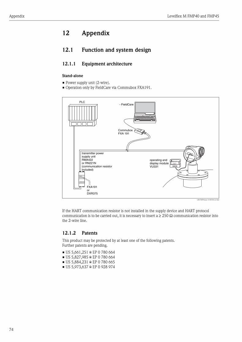
Appendix Levelflex M FMP40 and FMP45
74
12 Appendix
12.1 Function and system design
12.1.1 Equipment architecture
Stand-alone
• Power supply unit (2-wire).• Operation only by FieldCare via Commubox FXA191.
L00-FMP4xxxx-14-00-06-en-022
If the HART communication resistor is not installed in the supply device and HART protocol communication is to be carried out, it is necessary to insert a ≥ 250 Ω communication resistor into the 2-wire line.
12.1.2 PatentsThis product may be protected by at least one of the following patents.Further patents are pending.
• US 5,661,251 i EP 0 780 664• US 5,827,985 i EP 0 780 664• US 5,884,231 i EP 0 780 665• US 5,973,637 i EP 0 928 974
ENDRESS + HAUSER
E+–
ENDRESS + HAUSERRMA 422
- FieldCare
FXA191orDXR375
transmitter powersupply unitRMA422or RN221N(communication resistorincluded)
PLC
CommuboxFXA 191
operating anddisplay moduleVU331

Levelflex M FMP40 and FMP45 Appendix
75

Appendix Levelflex M FMP40 and FMP45
76

Levelflex M FMP40 and FMP45 Index
77
Index
AAccessories . . . . . . . . . . . . . . . . . . . . . . . . . . . . . . . . . . . . 56Alarm . . . . . . . . . . . . . . . . . . . . . . . . . . . . . . . . . . . . . . . . 31
CCE mark . . . . . . . . . . . . . . . . . . . . . . . . . . . . . . . . . . . . . . 13Commissioning . . . . . . . . . . . . . . . . . . . . . . . . . . . . . . . . . 32Commubox. . . . . . . . . . . . . . . . . . . . . . . . . . . . . . . . . . . . 27Commubox FXA 191 HART . . . . . . . . . . . . . . . . . . . . . . . 56Commuwin II . . . . . . . . . . . . . . . . . . . . . . . . . . . . . . . . . . 27Connecting . . . . . . . . . . . . . . . . . . . . . . . . . . . . . . . . . . . . 27
Ddeclaration of conformity. . . . . . . . . . . . . . . . . . . . . . . . . . 13Degree of protection . . . . . . . . . . . . . . . . . . . . . . . . . . . . . 28Designated use . . . . . . . . . . . . . . . . . . . . . . . . . . . . . . . . . . 4Dimensions . . . . . . . . . . . . . . . . . . . . . . . . . . . . . . . . . . . . 16DXR 375. . . . . . . . . . . . . . . . . . . . . . . . . . . . . . . . . . . . . . 27
EEquipotential bonding . . . . . . . . . . . . . . . . . . . . . . . . . . . . 28Error messages . . . . . . . . . . . . . . . . . . . . . . . . . . . . . . 31, 59Ersatzteile . . . . . . . . . . . . . . . . . . . . . . . . . . . . . . . . . . . . . 62Ex(-)approval . . . . . . . . . . . . . . . . . . . . . . . . . . . . . . . . . . 71Exterior cleaning . . . . . . . . . . . . . . . . . . . . . . . . . . . . . . . . 55Ex-Zulassung . . . . . . . . . . . . . . . . . . . . . . . . . . . . . . . . . . . 6
FF12 housing . . . . . . . . . . . . . . . . . . . . . . . . . . . . . . . . . . . 23FHX40 . . . . . . . . . . . . . . . . . . . . . . . . . . . . . . . . . . . . . . . 57FXA 191 . . . . . . . . . . . . . . . . . . . . . . . . . . . . . . . . . . . . . . 27FXA 193 . . . . . . . . . . . . . . . . . . . . . . . . . . . . . . . . . . . . . . 27
GGrundabgleich . . . . . . . . . . . . . . . . . . . . . . . . . . . . . . . . . 33
HHART . . . . . . . . . . . . . . . . . . . . . . . . . . . . . . . . . . . . . 25, 27
KKey assignment . . . . . . . . . . . . . . . . . . . . . . . . . . . . . . . . . 29
MMaintenance . . . . . . . . . . . . . . . . . . . . . . . . . . . . . . . . . . . 55Mounting . . . . . . . . . . . . . . . . . . . . . . . . . . . . . . . . . . . . . 14
NNameplate . . . . . . . . . . . . . . . . . . . . . . . . . . . . . . . . . . . . . 6
OOperation . . . . . . . . . . . . . . . . . . . . . . . . . . . . . . . . . . . . . 29Operational safety . . . . . . . . . . . . . . . . . . . . . . . . . . . . . . . . 4Ordering structure. . . . . . . . . . . . . . . . . . . . . . . . . . . . . . . . 6
RRepairs . . . . . . . . . . . . . . . . . . . . . . . . . . . . . . . . . . . . . . . 55Repairs to Ex-approved devices . . . . . . . . . . . . . . . . . . . . . 55Replacement . . . . . . . . . . . . . . . . . . . . . . . . . . . . . . . . . . . 55
Return. . . . . . . . . . . . . . . . . . . . . . . . . . . . . . . . . . . . . . . . 64RMA 422 . . . . . . . . . . . . . . . . . . . . . . . . . . . . . . . . . . . . . 27RN 221 N . . . . . . . . . . . . . . . . . . . . . . . . . . . . . . . . . . . . . 27
SSafety conventions and symbols . . . . . . . . . . . . . . . . . . . . . . 5Software history. . . . . . . . . . . . . . . . . . . . . . . . . . . . . . . . . 64Spare parts. . . . . . . . . . . . . . . . . . . . . . . . . . . . . . . . . . . . . 60System error messages . . . . . . . . . . . . . . . . . . . . . . . . . . . . 59
TT12 housing . . . . . . . . . . . . . . . . . . . . . . . . . . . . . . . . . . . 24Technical data . . . . . . . . . . . . . . . . . . . . . . . . . . . . . . . . . . 65Terminal compartment . . . . . . . . . . . . . . . . . . . . . . . . . . . 25ToF Tool . . . . . . . . . . . . . . . . . . . . . . . . . . . . . . . . . . . . . . 27Trouble-shooting . . . . . . . . . . . . . . . . . . . . . . . . . . . . . . . . 58Trouble-shooting instructions. . . . . . . . . . . . . . . . . . . . . . . 58
WWarning . . . . . . . . . . . . . . . . . . . . . . . . . . . . . . . . . . . . . . 31Weather protection cover . . . . . . . . . . . . . . . . . . . . . . . . . 56Wiring. . . . . . . . . . . . . . . . . . . . . . . . . . . . . . . . . . . . . . . . 23

Levelflex M FMP40 and FMP45 Index
78

!
" #"
$" " "
%" %" &"
'!(
)
*
%" %"
"
" "
+),"
-"
'( '%(
SAFE

www.endress.com/worldwide
BA327F/00/en/03.05Nr. 52027874CCS/FM+SGML 6.0/ProMoDo 52027874