Ölflex unitronic ® epic skintop etherline hitronic …
TRANSCRIPT

ÖLFLEX® | UNITRONIC® | EPIC® | SKINTOP® | ETHERLINE® | HITRONIC® | SILVYN® | FLEXIMARK®
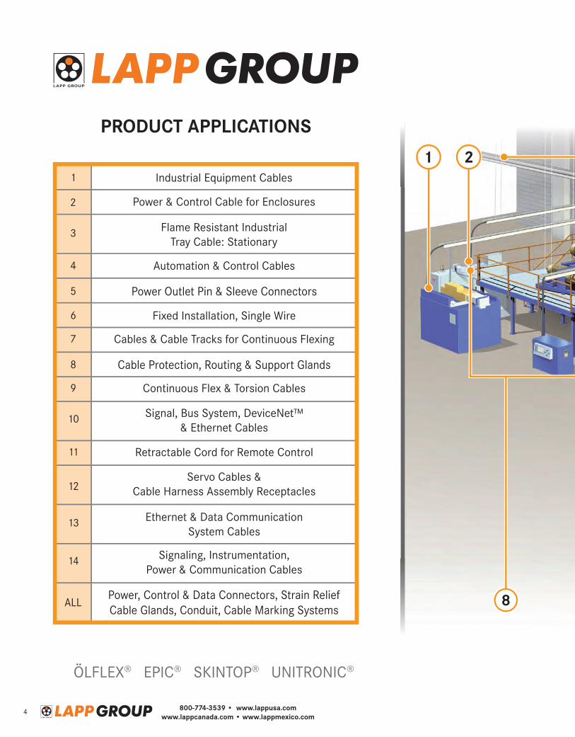
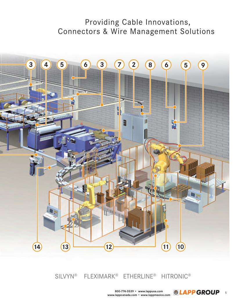
AutomationGuidefor Servo Motors/Drives and BUS Systems
Automation Make the right connection.

Make the right connection.At the Lapp Group we understand the critical role electrical connectivity products play in a wide array of industrial manufacturing applications. And how our customers depend on the quality, performance and durability of Lapp’s cable and connectivity solutions to keep their facilities and lines up and running, even in the most demanding conditions.
Helping our customers meet productivity goals at the lowest cost of ownership is the single focus of everything we do. Helping them make the right connection.
When you choose the Lapp Group you connect with a group of industry experts who embrace the company’s rich history of developing solutions that enable our customers to achieve optimum productivity and greater business success. You’ll have access to a robust line of products that provide more uptime and reduce downtime, no matter the job at hand. You’ll connect with a global company that combines international capabilities with domestic manufacturing; which ensures the utmost in product quality and availability. And you’ll connect with unrivaled customer support that is with you every step of the way.
First established in Germany in the 1950s and in the US in 1976, Lapp Group North America is headquartered in a newly renovated 130,000 square foot facility in Florham Park, New Jersey. The North American facility includes our state-of-the-art cable manufacturing plant, Lapp Cable Works. Lapp’s domestic manufacturing enables a fast and flexible focus on customer needs, greater inventory and the ability to meet demanding needs quickly. Additionally, Lapp has invested in engineering know-how to develop new products, and to support real-world applications with an in-house UL Certified Test Data Lab that is unique in the industry.
Lapp Group’s complete connectivity solutions for industrial machine and infrastructure applications include a full suite of power and control cable, connectors, accessories and systems. These products and solutions are specifically tailored for a wide array of industries including automotive, food and beverage, wind energy, oil and gas, packaging and manufacturing.
Lapp brands include; ÖLFLEX®, UNITRONIC®, EPIC®, SKINTOP®, ETHERLINE®, HITRONIC®, SILVYN®, AND FLEXIMARK®
We welcome the opportunity to collaborate with you to make the right connection.

A Full Suite of Connectivity Solutions• Machine Cables for all applications
• TC-ER Rated Tray Cables
• Cables for major VFDs and manufacturers of servo motors and drives
• Industrial Grade Data Cables for signal, control and networks
• Environmentally Protected Industrial Connectors for power, control, and data; including Rectangular, Circular, and IEC Pin and Sleeve Connectors
• Strain Relief Products
• Cable Management Accessories including: Conduit, Track, Sleeving and Marking Systems
Industry Leading Expertise• Specially trained national sales team
• In-house team of engineers
• State-of-the-art cable manufacturing in North America
• North American based UL Client test Data Lab
• Worldwide logistics centers
• Extensive product inventory
• In-house Systems Group providing Custom Assemblies and Populated Cable Tracks
• ISO Certified
800-774-3539 • www.lappusa.comwww.lappcanada.com • www.lappmexico.com
4
800-774-3539 • www.lappusa.comwww.lappcanada.com • www.lappmexico.com
5
800-774-3539 • www.lappusa.comwww.lappcanada.com • www.lappmexico.com
6
Bus Cable Attributes for UNITRONIC® Bus Cable 10
UNITRONIC® BUS DeviceNet™ Gray 11For DeviceNet Bus Systems; Stationary & Continuous Flex Applications; 120 Ω
UNITRONIC® BUS DeviceNet™ Violet 11For DeviceNet Bus Systems; Stationary & Continuous Flex Applications; 120 Ω
DeviceNet™ Field Wireable Connectors 12
DeviceNet™ Cordsets 13
UNITRONIC® BUS PB 15For PROFIBUS-DP/FMS/FIP Bus Systems; Stationary Applications; 150 Ω
UNITRONIC® BUS PB FD 15For PROFIBUS-DP/FMS/FIP Bus Systems; Continuous Flex Applications; 150 Ω
UNITRONIC® BUS PB TORSION 15For PROFIBUS-DP/FMS/FIP Bus Systems; Torsion Applications; 150 Ω
EPIC® Data PROFIBUS Connectors 16
PROFIBUS Field Wireable M12 Connectors 16
PROFIBUS Cordsets 17
UNITRONIC® BUS CAN 18For CAN Bus Systems; Stationary Applications; 120 Ω
UNITRONIC® BUS CAN FD 18For CAN Bus Systems; Continuous Flex Applications; 120 Ω
UNITRONIC® BUS LD/LD FD P 19For RS485/RS422 Bus Systems; Stationary & Continuous Flex Applications; 100 - 120 Ω
UNITRONIC® SENSOR FD 19Multi-Conductor Continuous Flex Communication Cable with PUR Jacket; 300V
General Specifications for Bus Cordsets 20DeviceNet™ and PROFIBUS Cordsets
Bus Cable Attributes for ETHERLINE® Cable 21
ETHERLINE® 2 Pair: CAT.5/5e 22Industrial Ethernet Cables for Stationary, Flexing & Continuous Flex Applications
ETHERLINE® 2 Pair: CAT.5 TORSION 22Industrial Ethernet Cable Suitable for Torsion Stress
ETHERLINE® 4 Pair: CAT.5e 23Industrial Ethernet Cables for Stationary, Flexing & Continuous Flex Applications
ETHERLINE® 4 Pair: CAT.6 23Industrial Ethernet Cable for Continuous Flex Applications
ETHERLINE® 4 Pair: CAT.6A/7; Stationary 24Industrial Ethernet Cable for Stationary Applications
Products for Bus Systems
800-774-3539 • www.lappusa.comwww.lappcanada.com • www.lappmexico.com
7
ÖLFLEX® VFD SLIM 35Reduced-Diameter VFD Cable; 600/1000V; UL & c(UL) TC Approval
ÖLFLEX® VFD XL 35Precision Control VFD Cable; 600/1000V; UL & c(UL) TC Approval
ÖLFLEX® VFD with Signal 36Flexible VFD Cable with a Pair for Signal or Temperature Sensor; 600/1000V; UL & c(UL) TC Approval
V 2000 36VFD Symmetrical 2kV Motor Supply Cable for Large HP VFD Drives; UL TC-ER Approval
ÖLFLEX® SERVO FD 796 P 37High-Acceleration Continuous Flex Servo Cable with PUR Jacket; Unshielded
ÖLFLEX® SERVO FD 796 CP 38High-Acceleration Continuous Flex Servo Cable with PUR Jacket; Shielded
ÖLFLEX® SERVO FD 798 CP 39High-Acceleration Continuous Flex Encoder & Resolver Cable; UL & CSA Approval
ÖLFLEX® CHAIN 896 P 40High-Acceleration Continuous Flexing Control Cable with PUR Jacket
C 304 29Multi-Conductor, Low-Voltage Communication, Audio & Control Cable; Unshielded
C 304 S 30Multi-Conductor, Low-Voltage Communication, Audio & Control Cable; Shielded
D 304 IS 31Multi-Pair, Low-Voltage Communication, Audio, Signal & Control Cable; Individually Shielded Pairs
D 304 OS 32Multi-Pair, Low-Voltage Communication, Audio, Signal & Control Cable; Overall Shield
UNITRONIC® 300 33Multi-Conductor, 300V Flexible Industrial Signal & Control Cable; Unshielded
UNITRONIC® 300 S 34Multi-Conductor, 300V Flexible Industrial Signal & Control Cable; Shielded
Electronic Cable
Products for Motors & Drives
ETHERLINE® 4 Pair: CAT.6A; Continuous Flex 24Industrial Ethernet Cable for Continuous Flex Applications
ETHERLINE® 4 Pair: CAT.6A TORSION 24Industrial Ethernet Cable for Torsion Stress
RJ45/M12 Field Wireable Connectors 25
Ethernet Cordsets 26
General Specifications for Bus Cordsets 28Ethernet and PROFINET Cordsets
800-774-3539 • www.lappusa.comwww.lappcanada.com • www.lappmexico.com
8
Servo Cables according to SIEMENS® Standard 6FX 8 Plus 41Highly Flexible Servo Cable for High-Acceleration Continuous Flexing Motion
Servo Cables according to INDRAMAT® Standard INK 42Continuous Flex Cable according to INDRAMAT® Standard INK
AB Assemblies for Rockwell Automation Motors 43Feedback & Power Cable Assemblies for Flexing Applications
AB Legacy Assemblies for Rockwell Automation Motors 45Legacy Feedback & Power Cable Assemblies
Servo Assemblies according to SIEMENS® Standards 47SIEMENS® Standards 6FX 8002 & 6FX 5002
Servo LK-INX Assemblies according to INDRAMAT® Standards 48INDRAMAT® Standards IKG/RKL & IKS/RKG
Servo Assemblies according to LENZE® Standard 49
Servo Assemblies according to SEW™ Standard 49
Environmentally Protected Industrial Connectors
EPIC® Connectors 50For Power, Signal/Control & Data Applications
EPIC® Connectors to Cable Cross Reference 51Find the Right Connector for Your Cable
EPIC® Rectangular Housings Overview 55
EPIC® Rectangular Inserts Overview 56
EPIC® ULTRA HB Housings 57
EPIC® Rectangular Inserts 58HBE 6, HBS 6, Mixed Power & MC Modular Inserts
EPIC® Rectangular Insert Contacts 60
EPIC® Tools 61Rectangular Connector Crimp Tools & Hole Punch
Remote Access Ports 62
EPIC® CIRCON LS1 Circular Connectors 63
EPIC® CIRCON M23 Circular Connectors 64
800-774-3539 • www.lappusa.comwww.lappcanada.com • www.lappmexico.com
9
SKINTOP® Cable Glands 66Strain Relief Cable Glands: Secured by a Single Turn of the Hand
SKINTOP® SL/SLR 67Strain Relief with PG Thread
SKINTOP® SLM/SLRM 68Strain Relief with Metric Thread
SKINTOP® SLN/SLRN 69Strain Relief with NPT Thread
SKINTOP® CUBE 69Multi-Cable Bushing System
SKINTOP® CLICK/CLICK-R 70Strain Relief with Quick “Click” Insertion System
SKINTOP® INOX/INOX-R 70Stainless Steel Strain Relief with Metric Thread
SKINTOP® BRUSH 71Nickel-Plated Brass Strain Relief for EMC Applications with NPT or Metric Thread
SKINDICHT® SM-PE Locknuts 71Nickel-Plated Brass Grounding Locknuts for PG & Metric Cable Glands
SKINTOP® MS-SC/MS-SC-XL 72Nickel-Plated Brass Strain Relief for EMC Applications with NPT, PG & Metric Thread
Cable Attributes 73Oil Resistance, Fire Restistance, Motion & Mechanical Protection Attributes
Color Code Charts 75
VFD Cable Selection Guide 77Motor Properties & Voltage Drop Factors
Size Conversion 77American Wire Gauge (AWG) to mm2
IP Ratings 78Modes of Protection per DIN VDE 0470-1 (IEC EN 60529)
Conversion Factors 79
Strain Relief Cable Glands
Technical Information and Reference
800-774-3539 • www.lappusa.comwww.lappcanada.com • www.lappmexico.com
10Recommended SKINTOP® assumes minimal OD variance. Additional configurations are available. Photographs are not to scale and are not true representations of the products in question. For current information go to our website. If not otherwise specified, all values relating to the product are nominal values.
BUS
SYST
EMS
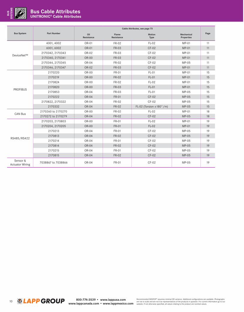
UNITRONIC® Cable AttributesBus Cable Attributes
Bus System Part Number
Cable Attributes, see page 73
PageOil Resistance
Flame Resistance
MotionType
Mechanical Properties
DeviceNet™
4001, 4002 OR-01 FR-02 FL-02 MP-01 11
6001, 6002 OR-01 FR-03 CF-02 MP-01 11
2170342, 2170343 OR-02 FR-03 CF-02 MP-01 11
2170340, 2170341 OR-00 FR-03 CF-02 MP-01 11
2170344, 2170345 OR-04 FR-02 CF-02 MP-05 11
2170346, 2170347 OR-02 FR-03 CF-02 MP-01 11
PROFIBUS
2170220 OR-00 FR-01 FL-01 MP-01 15
2170219 OR-00 FR-02 FL-01 MP-01 15
2170824 OR-00 FR-02 FL-02 MP-01 15
2170820 OR-00 FR-03 FL-01 MP-01 15
2170853 OR-04 FR-03 FL-01 MP-05 15
2170222 OR-04 FR-01 CF-02 MP-05 15
2170822, 2170322 OR-04 FR-02 CF-02 MP-05 15
2170332 OR-04 FR-02 FL-02 (Torsion ±180°/m) MP-05 15
CAN Bus2170260 to 2170270 OR-00 FR-02 FL-02 MP-01 18
2170272 to 2170279 OR-04 FR-02 CF-02 MP-05 18
RS485/RS422
2170203, 2170803 OR-00 FR-01 FL-02 MP-01 19
2170204, 2170205 OR-00 FR-01 FL-02 MP-01 19
2170213 OR-04 FR-01 CF-02 MP-05 19
2170813 OR-04 FR-02 CF-02 MP-05 19
2170214 OR-04 FR-01 CF-02 MP-05 19
2170814 OR-04 FR-02 CF-02 MP-05 19
2170215 OR-04 FR-01 CF-02 MP-05 19
2170815 OR-04 FR-02 CF-02 MP-05 19
Sensor & Actuator Wiring
7038867 to 7038866 OR-04 FR-01 CF-02 MP-05 19
800-774-3539 • www.lappusa.comwww.lappcanada.com • www.lappmexico.com
11Recommended SKINTOP® assumes minimal OD variance. Additional configurations are available. Photographs are not to scale and are not true representations of the products in question. For current information go to our website. If not otherwise specified, all values relating to the product are nominal values.
BUS
SYSTEMS
BUS
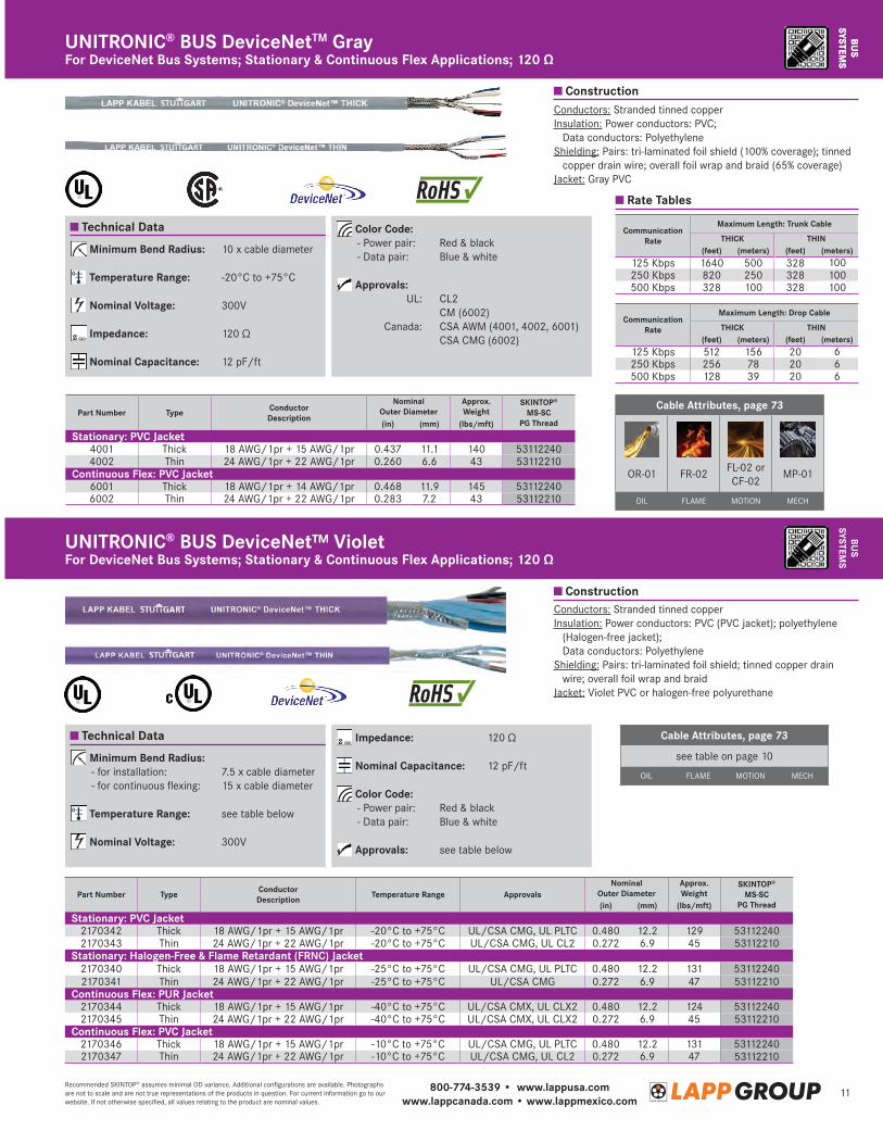
SYSTEMSFor DeviceNet Bus Systems; Stationary & Continuous Flex Applications; 120 ΩUNITRONIC® BUS DeviceNetTM Gray
Cable Attributes, page 73
OR-01 FR-02 FL-02 orCF-02
MP-01
OIL FLAME MOTION MECH
Minimum Bend Radius: 10 x cable diameter
Temperature Range: -20°C to +75°C
Nominal Voltage: 300V
Impedance: 120 Ω
Nominal Capacitance: 12 pF/ft
Color Code: - Power pair: Red & black - Data pair: Blue & white
Approvals: UL: CL2 CM (6002) Canada: CSA AWM (4001, 4002, 6001) CSA CMG (6002)
Technical Data
Conductors: Stranded tinned copperIn sulation: Power conductors: PVC;
Data conductors: PolyethyleneS hielding: Pairs: tri-laminated foil shield (100% coverage); tinned
copper drain wire; overall foil wrap and braid (65% coverage)Jacket: Gray PVC
Part Number Type Conductor Description
Nominal Outer Diameter
Approx. Weight
SKINTOP® MS-SC
PG Thread(in) (mm) (lbs/mft)
Stationary: PVC Jacket4001 Thick 18 AWG/1pr + 15 AWG/1pr 0.437 11.1 140 531122404002 Thin 24 AWG/1pr + 22 AWG/1pr 0.260 6.6 43 53112210
Continuous Flex: PVC Jacket6001 Thick 18 AWG/1pr + 14 AWG/1pr 0.468 11.9 145 531122406002 Thin 24 AWG/1pr + 22 AWG/1pr 0.283 7.2 43 53112210
Communication Rate
Maximum Length: Trunk Cable
THICK THIN(feet) (meters) (feet) (meters)
125 Kbps 1640 500 328 100250 Kbps 820 250 328 100500 Kbps 328 100 328 100
Rate Tables
Communication Rate
Maximum Length: Drop Cable
THICK THIN(feet) (meters) (feet) (meters)
125 Kbps 512 156 20 6250 Kbps 256 78 20 6500 Kbps 128 39 20 6
BUS
SYSTEMSFor DeviceNet Bus Systems; Stationary & Continuous Flex Applications; 120 Ω
UNITRONIC® BUS DeviceNet™ Violet
Construction
Technical Data
Conductors: Stranded tinned copperIn sulation: Power conductors: PVC (PVC jacket); polyethylene
(Halogen-free jacket); Data conductors: Polyethylene
S hielding: Pairs: tri-laminated foil shield; tinned copper drain wire; overall foil wrap and braid
Jacket: Violet PVC or halogen-free polyurethane
Minimum Bend Radius: - for installation: 7.5 x cable diameter - for continuous flexing: 15 x cable diameter
Temperature Range: see table below
Nominal Voltage: 300V
Impedance: 120 Ω
Nominal Capacitance: 12 pF/ft
Color Code: - Power pair: Red & black - Data pair: Blue & white
Approvals: see table below
Part Number Type Conductor Description Temperature Range Approvals
Nominal Outer Diameter
Approx. Weight
SKINTOP® MS-SC
PG Thread(in) (mm) (lbs/mft)
Stationary: PVC Jacket2170342 Thick 18 AWG/1pr + 15 AWG/1pr -20°C to +75°C UL/CSA CMG, UL PLTC 0.480 12.2 129 531122402170343 Thin 24 AWG/1pr + 22 AWG/1pr -20°C to +75°C UL/CSA CMG, UL CL2 0.272 6.9 45 53112210
Stationary: Halogen-Free & Flame Retardant (FRNC) Jacket2170340 Thick 18 AWG/1pr + 15 AWG/1pr -25°C to +75°C UL/CSA CMG, UL PLTC 0.480 12.2 131 531122402170341 Thin 24 AWG/1pr + 22 AWG/1pr -25°C to +75°C UL/CSA CMG 0.272 6.9 47 53112210
Continuous Flex: PUR Jacket2170344 Thick 18 AWG/1pr + 15 AWG/1pr -40°C to +75°C UL/CSA CMX, UL CLX2 0.480 12.2 124 531122402170345 Thin 24 AWG/1pr + 22 AWG/1pr -40°C to +75°C UL/CSA CMX, UL CLX2 0.272 6.9 45 53112210
Continuous Flex: PVC Jacket2170346 Thick 18 AWG/1pr + 15 AWG/1pr -10°C to +75°C UL/CSA CMG, UL PLTC 0.480 12.2 131 531122402170347 Thin 24 AWG/1pr + 22 AWG/1pr -10°C to +75°C UL/CSA CMG, UL CL2 0.272 6.9 47 53112210
Cable Attributes, page 73
see table on page 10
OIL FLAME MOTION MECH
Construction
800-774-3539 • www.lappusa.comwww.lappcanada.com • www.lappmexico.com
12Recommended SKINTOP® assumes minimal OD variance. Additional configurations are available. Photographs are not to scale and are not true representations of the products in question. For current information go to our website. If not otherwise specified, all values relating to the product are nominal values.
BUS
SYST
EMS
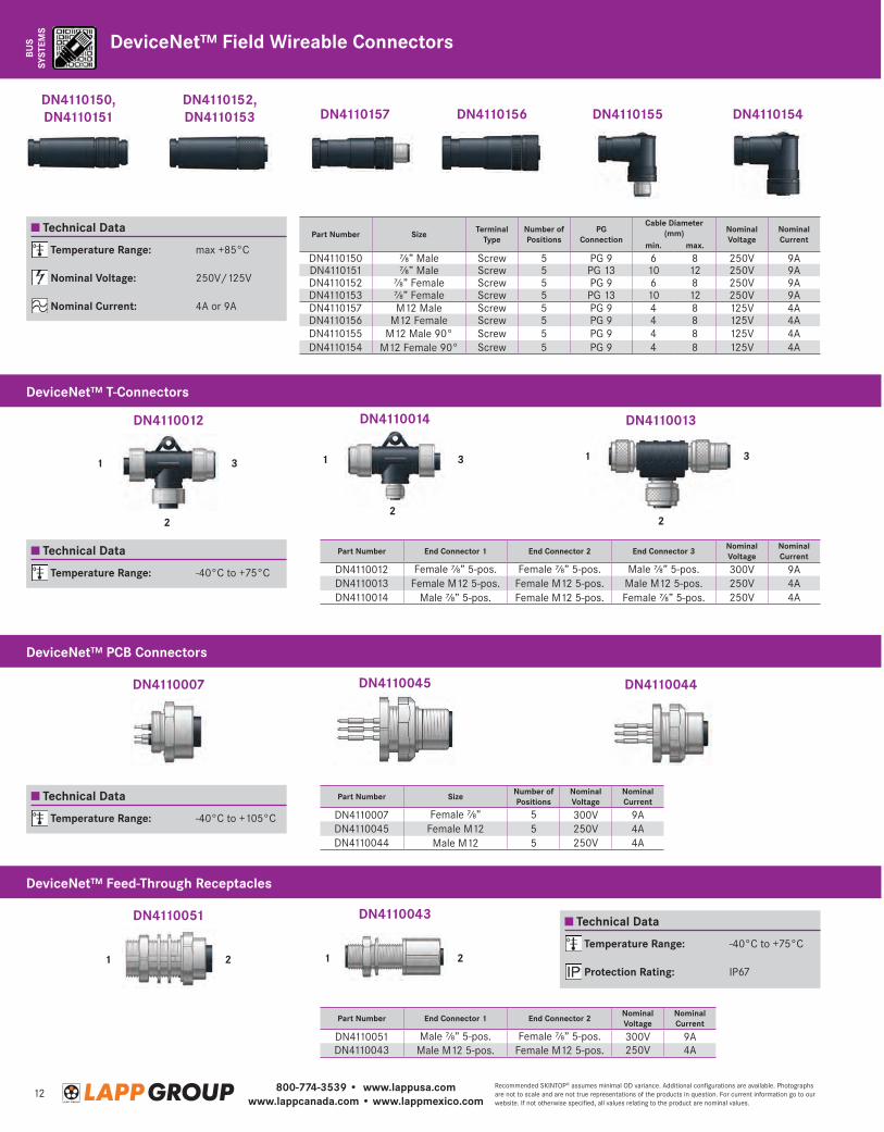
Temperature Range: max +85°C
Nominal Voltage: 250V/125V
Nominal Current: 4A or 9A
Temperature Range: -40°C to +75°C
Temperature Range: -40°C to +105°C
Temperature Range: -40°C to +75°C
Protection Rating: IP67
Technical Data
Technical Data
Technical Data
Technical Data
DN4110156 DN4110155DN4110152, DN4110153
DN4110150, DN4110151 DN4110157 DN4110154
Part Number Size Terminal Type
Number of Positions
PG Connection
Cable Diameter (mm) Nominal
VoltageNominal Current
min. max.
DN4110150 ⅞” Male Screw 5 PG 9 6 8 250V 9ADN4110151 ⅞” Male Screw 5 PG 13 10 12 250V 9ADN4110152 ⅞” Female Screw 5 PG 9 6 8 250V 9ADN4110153 ⅞” Female Screw 5 PG 13 10 12 250V 9ADN4110157 M12 Male Screw 5 PG 9 4 8 125V 4ADN4110156 M12 Female Screw 5 PG 9 4 8 125V 4ADN4110155 M12 Male 90° Screw 5 PG 9 4 8 125V 4ADN4110154 M12 Female 90° Screw 5 PG 9 4 8 125V 4A
DN4110014
DN4110045
DN4110043
DN4110013
DN4110044
DN4110012
DN4110007
DN4110051
1 3
2
1 3
2
1
1 1
3
2 2
2
Part Number End Connector 1 End Connector 2 End Connector 3 Nominal Voltage
Nominal Current
DN4110012 Female ⅞” 5-pos. Female ⅞” 5-pos. Male ⅞” 5-pos. 300V 9ADN4110013 Female M12 5-pos. Female M12 5-pos. Male M12 5-pos. 250V 4ADN4110014 Male ⅞” 5-pos. Female M12 5-pos. Female ⅞” 5-pos. 250V 4A
Part Number Size Number of Positions
Nominal Voltage
Nominal Current
DN4110007 Female ⅞” 5 300V 9ADN4110045 Female M12 5 250V 4ADN4110044 Male M12 5 250V 4A
Part Number End Connector 1 End Connector 2 Nominal Voltage
Nominal Current
DN4110051 Male ⅞” 5-pos. Female ⅞” 5-pos. 300V 9ADN4110043 Male M12 5-pos. Female M12 5-pos. 250V 4A
DeviceNet™ T-Connectors
DeviceNet™ PCB Connectors
DeviceNet™ Feed-Through Receptacles
DeviceNet™ Field Wireable Connectors
800-774-3539 • www.lappusa.comwww.lappcanada.com • www.lappmexico.com
13Recommended SKINTOP® assumes minimal OD variance. Additional configurations are available. Photographs are not to scale and are not true representations of the products in question. For current information go to our website. If not otherwise specified, all values relating to the product are nominal values.
BUS
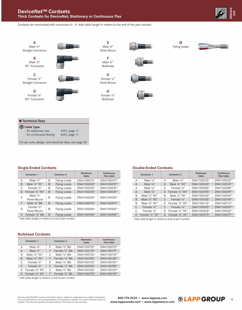
SYSTEMSThick Cordsets for DeviceNet; Stationary or Continuous FlexDeviceNet™ Cordsets
Technical Data
Cable Type: - for stationary use: 4001, page 11 - for continuous flexing: 6001, page 11
For pin outs, design, and electrical data, see page 20
AMale ⅞”
Straight Connector
BMale ⅞”
90° Connector
FMale ⅞”Bulkhead
CFemale ⅞”
Straight Connector
DFemale ⅞”
90° Connector
ØFlying Leads
EMale ⅞”
Panel Mount
GFemale ⅞”
Panel Mount
HFemale ⅞”Bulkhead
Cordsets are terminated with connectors A - H. Add cable length in meters to the end of the part number.
Single-Ended Cordsets
Bulkhead Cordsets
* Add cable length in meters to end of part number
* Add cable length in meters to end of part number
* Add cable length in meters to end of part number
Double-Ended Cordsets
Connector 1 Connector 2 Stationary Cable
Continuous Flex Cable
A Male ⅞” Ø Flying Leads DN4110001S* DN4110001F*B Male ⅞” 90° Ø Flying Leads DN4110002S* DN4110002F*C Female ⅞” Ø Flying Leads DN4110003S* DN4110003F*D Female ⅞” 90° Ø Flying Leads DN4110004S* DN4110004F*
EMale ⅞”
Panel MountØ Flying Leads DN4110005S* DN4110005F*
F Male ⅞” Blk Ø Flying Leads DN4110097S* DN4110097F*
GFemale ⅞”
Panel MountØ Flying Leads DN4110006S* DN4110006F*
H Female ⅞” Blk Ø Flying Leads DN4110098S* DN4110098F*
Connector 1 Connector 2 Stationary Cable
Continuous Flex Cable
A Male ⅞” E Male ⅞” Blk DN4110072S* DN4110072F*A Male ⅞” F Female ⅞” Blk DN4110017S* DN4110017F*B Male ⅞” 90° E Male ⅞” Blk DN4110073S* DN4110073F*B Male ⅞” 90° F Female ⅞” Blk DN4110018S* DN4110018F*C Female ⅞” E Male ⅞” Blk DN4110015S* DN4110015F*C Female ⅞” F Female ⅞” Blk DN4110078S* DN4110078F*D Female ⅞” 90° E Male ⅞” Blk DN4110016S* DN4110016F*D Female ⅞” 90° F Female ⅞” Blk DN4110079S* DN4110079F*
Connector 1 Connector 2 Stationary Cable
Continuous Flex Cable
A Male ⅞” A Male ⅞” DN4110052S* DN4110052F*A Male ⅞” B Male ⅞” 90° DN4110053S* DN4110053F*A Male ⅞” C Female ⅞” DN4110008S* DN4110008F*A Male ⅞” D Female ⅞” 90° DN4110009S* DN4110009F*B Male ⅞” 90° B Male ⅞” 90° DN4110054S* DN4110054F*B Male ⅞” 90° C Female ⅞” DN4110010S* DN4110010F*B Male ⅞” 90° D Female ⅞” 90° DN4110011S* DN4110011F*C Female ⅞” C Female ⅞” DN4110055S* DN4110055F*C Female ⅞” D Female ⅞” 90° DN4110056S* DN4110056F*D Female ⅞” 90° D Female ⅞” 90° DN4110057S* DN4110057F*
800-774-3539 • www.lappusa.comwww.lappcanada.com • www.lappmexico.com
14Recommended SKINTOP® assumes minimal OD variance. Additional configurations are available. Photographs are not to scale and are not true representations of the products in question. For current information go to our website. If not otherwise specified, all values relating to the product are nominal values.
BUS
SYST
EMS
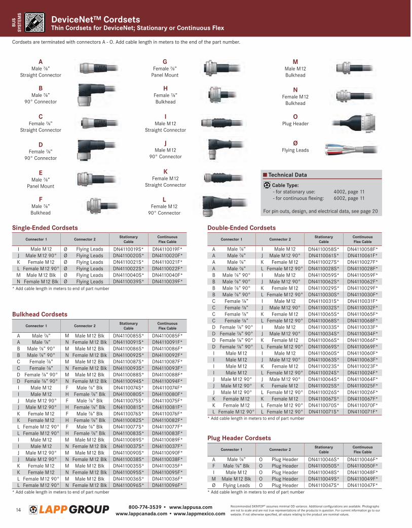
DeviceNet™ CordsetsThin Cordsets for DeviceNet; Stationary or Continuous Flex
Technical Data
Cable Type: - for stationary use: 4002, page 11 - for continuous flexing: 6002, page 11
For pin outs, design, and electrical data, see page 20
AMale ⅞”
Straight Connector
BMale ⅞”
90° Connector
FMale ⅞”Bulkhead
JMale M12
90° Connector
CFemale ⅞”
Straight Connector
DFemale ⅞”
90° Connector
ØFlying Leads
OPlug Header
NFemale M12
Bulkhead
EMale ⅞”
Panel Mount
IMale M12
Straight Connector
GFemale ⅞”
Panel Mount
KFemale M12
Straight Connector
HFemale ⅞”Bulkhead
MMale M12Bulkhead
LFemale M12
90° Connector
Cordsets are terminated with connectors A - O. Add cable length in meters to the end of the part number.
Single-Ended Cordsets
* Add cable length in meters to end of part number
* Add cable length in meters to end of part number
* Add cable length in meters to end of part number
* Add cable length in meters to end of part number
Double-Ended Cordsets
Bulkhead Cordsets
Connector 1 Connector 2 Stationary Cable
Continuous Flex Cable
I Male M12 Ø Flying Leads DN4110019S* DN4110019F*J Male M12 90° Ø Flying Leads DN4110020S* DN4110020F*K Female M12 Ø Flying Leads DN4110021S* DN4110021F*L Female M12 90° Ø Flying Leads DN4110022S* DN4110022F*M Male M12 Blk Ø Flying Leads DN4110040S* DN4110040F*N Female M12 Blk Ø Flying Leads DN4110039S* DN4110039F*
Plug Header Cordsets
Connector 1 Connector 2 Stationary Cable
Continuous Flex Cable
A Male ⅞” O Plug Header DN4110046S* DN4110046F*F Male ⅞” Blk O Plug Header DN4110050S* DN4110050F*I Male M12 O Plug Header DN4110048S* DN4110048F*
M Male M12 Blk O Plug Header DN4110049S* DN4110049F*Ø Flying Leads O Plug Header DN4110047S* DN4110047F*
Connector 1 Connector 2 Stationary Cable
Continuous Flex Cable
A Male ⅞” I Male M12 DN4110058S* DN4110058F*A Male ⅞” J Male M12 90° DN4110061S* DN4110061F*A Male ⅞” K Female M12 DN4110027S* DN4110027F*A Male ⅞” L Female M12 90° DN4110028S* DN4110028F*B Male ⅞” 90° I Male M12 DN4110059S* DN4110059F*B Male ⅞” 90° J Male M12 90° DN4110062S* DN4110062F*B Male ⅞” 90° K Female M12 DN4110029S* DN4110029F*B Male ⅞” 90° L Female M12 90° DN4110030S* DN4110030F*C Female ⅞” I Male M12 DN4110031S* DN4110031F*C Female ⅞” J Male M12 90° DN4110032S* DN4110032F*C Female ⅞” K Female M12 DN4110065S* DN4110065F*C Female ⅞” L Female M12 90° DN4110068S* DN4110068F*D Female ⅞” 90° I Male M12 DN4110033S* DN4110033F*D Female ⅞” 90° J Male M12 90° DN4110034S* DN4110034F*D Female ⅞” 90° K Female M12 DN4110066S* DN4110066F*D Female ⅞” 90° L Female M12 90° DN4110069S* DN4110069F*I Male M12 I Male M12 DN4110060S* DN4110060F*I Male M12 J Male M12 90° DN4110063S* DN4110063F*I Male M12 K Female M12 DN4110023S* DN4110023F*I Male M12 L Female M12 90° DN4110024S* DN4110024F*J Male M12 90° J Male M12 90° DN4110064S* DN4110064F*J Male M12 90° K Female M12 DN4110025S* DN4110025F*J Male M12 90° L Female M12 90° DN4110026S* DN4110026F*K Female M12 K Female M12 DN4110067S* DN4110067F*K Female M12 L Female M12 90° DN4110070S* DN4110070F*L Female M12 90° L Female M12 90° DN4110071S* DN4110071F*
Connector 1 Connector 2 Stationary Cable
Continuous Flex Cable
A Male ⅞” M Male M12 Blk DN4110085S* DN4110085F*A Male ⅞” N Female M12 Blk DN4110091S* DN4110091F*B Male ⅞” 90° M Male M12 Blk DN4110086S* DN4110086F*B Male ⅞” 90° N Female M12 Blk DN4110092S* DN4110092F*C Female ⅞” M Male M12 Blk DN4110087S* DN4110087F*C Female ⅞” N Female M12 Blk DN4110093S* DN4110093F*D Female ⅞” 90° M Male M12 Blk DN4110088S* DN4110088F*D Female ⅞” 90° N Female M12 Blk DN4110094S* DN4110094F*I Male M12 F Male ⅞” Blk DN4110074S* DN4110074F*I Male M12 H Female ⅞” Blk DN4110080S* DN4110080F*J Male M12 90° F Male ⅞” Blk DN4110075S* DN4110075F*J Male M12 90° H Female ⅞” Blk DN4110081S* DN4110081F*K Female M12 F Male ⅞” Blk DN4110076S* DN4110076F*K Female M12 H Female ⅞” Blk DN4110082S* DN4110082F*L Female M12 90° F Male ⅞” Blk DN4110077S* DN4110077F*L Female M12 90° H Female ⅞” Blk DN4110083S* DN4110083F*I Male M12 M Male M12 Blk DN4110089S* DN4110089F*I Male M12 N Female M12 Blk DN4110037S* DN4110037F*J Male M12 90° M Male M12 Blk DN4110090S* DN4110090F*J Male M12 90° N Female M12 Blk DN4110038S* DN4110038F*K Female M12 M Male M12 Blk DN4110035S* DN4110035F*K Female M12 N Female M12 Blk DN4110095S* DN4110095F*L Female M12 90° M Male M12 Blk DN4110036S* DN4110036F*L Female M12 90° N Female M12 Blk DN4110096S* DN4110096F*

800-774-3539 • www.lappusa.comwww.lappcanada.com • www.lappmexico.com
15Recommended SKINTOP® assumes minimal OD variance. Additional configurations are available. Photographs are not to scale and are not true representations of the products in question. For current information go to our website. If not otherwise specified, all values relating to the product are nominal values.
BUS
SYSTEMS
Construction
Construction
Technical Data
UNITRONIC® BUS PBFor PROFIBUS-DP/FMS/FIP Bus Systems; Stationary Applications; 150 Ω
BUS
SYSTEMS
Technical Data
Minimum Bend Radius: see table below
Temperature Range: - for stationary use: -40°C to +80°C - for flexible use: -30°C to +70°C - torsion: -25°C to +75°C
Impedance: 150 Ω ± 15 Ω
Nominal Capacitance: 9 pF/ft
Color Code: Red & green pair
Approvals: see table below
Conductors: Stranded bare copperInsulation: PolyethyleneShielding: Specially designed foil/tinned copper braidJacket: Violet polyurethane (PB Torsion: halogen-free
polyurethane)
UNITRONIC® BUS PB FD & PB TORSIONFor PROFIBUS-DP/FMS/FIP Bus Systems; Continuous Flex & Torsion Applications; 150 Ω
Minimum Bend Radius: - for installation: 10 x cable diameter
Temperature Range: - PVC: -40°C to +80°C - Halogen-free: -30°C to +80°C
Impedance: 150 Ω ± 15 Ω
Nominal Capacitance: 9 pF/ft
Color Code: Red & green pair
Approvals: see table below
Conductors: Solid and stranded bare copperInsulation: PolyethyleneShielding: Specially designed foil/tinned copper braidJacket: Violet PVC (except 2170853: halogen-free)
Communication Rate
Length of Cable Segment(feet) (meters)
93.75 Kbps 3936 1200187.5 Kbps 3280 1000500 Kbps 1312 4001.5 Mbps 656 200
12.0 Mbps 328 100
Maximum Cable Length by Bit Rate
Part Number Jacket Type Conductor Description Approvals
Nominal Outer Diameter
Approx. Weight
SKINTOP® MS-SC
PG Thread(in) (mm) (lbs/mft)
Stationary2170220 PVC 22 AWG/1pr — 0.315 8 50 531122202170219 PVC 22 AWG/1pr UL/CSA CMX 0.315 8 38 53112220
2170824* PVC 24 AWG/1pr, 7 wire UL/CSA CMG, UL CL3 0.315 8 37 53112220Stationary: Fast Connect
2170820 PVC 22 AWG/1pr UL/CSA CMG, UL CL3 0.315 8 56 531122202170853 Halogen-free 22 AWG/1pr UL/CSA CMG 0.315 8 50 53112220
*For applications where vibrations occur.
Part Number Jacket Type Conductor Description
Min. Bend Radius(x cable diameter) Approvals
Nominal Outer Diameter
Approx. Weight
SKINTOP® MS-SC
PG Thread(in) (mm) (lbs/mft)
Continuous Flex2170222 PUR 24 AWG/1pr 9 Torsion Rated 0.315 8 43 531122202170822 PUR 24 AWG/1pr 9 UL/CSA CMX, Torsion Rated 0.315 8 39 53112220
Continuous Flex: Fast Connect2170322 PUR 24 AWG/1pr 15 UL/CSA CMX 0.315 8 53 53112220
Torsion2170332 PUR 22 AWG/1pr 4 (stationary), 15 (flexible) UL/CSA CMX, Torsion Rated 0.315 8 44 53112220
Cable Attributes, page 73
see table on page 10
OIL FLAME MOTION MECH
Cable Attributes, page 73
see table on page 10
OIL FLAME MOTION MECH
800-774-3539 • www.lappusa.comwww.lappcanada.com • www.lappmexico.com
16Recommended SKINTOP® assumes minimal OD variance. Additional configurations are available. Photographs are not to scale and are not true representations of the products in question. For current information go to our website. If not otherwise specified, all values relating to the product are nominal values.
BUS
SYST
EMS
BUS
SYST
EMS
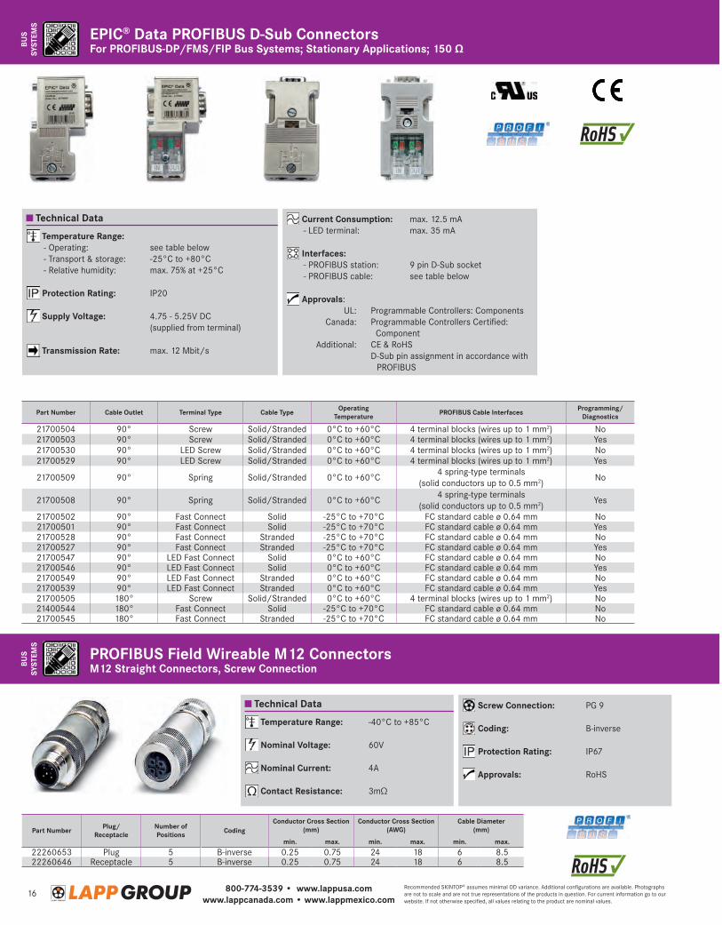
For PROFIBUS-DP/FMS/FIP Bus Systems; Stationary Applications; 150 ΩEPIC® Data PROFIBUS D-Sub Connectors
Technical Data
Temperature Range: - Operating: see table below - Transport & storage: -25°C to +80°C - Relative humidity: max. 75% at +25°C
Protection Rating: IP20
Supply Voltage: 4.75 - 5.25V DC (supplied from terminal)
Transmission Rate: max. 12 Mbit/s
Current Consumption: max. 12.5 mA - LED terminal: max. 35 mA
Interfaces: - PROFIBUS station: 9 pin D-Sub socket - PROFIBUS cable: see table below
Approvals: UL: Programmable Controllers: Components Canada: P rogrammable Controllers Certified:
Component Additional: CE & RoHS D -Sub pin assignment in accordance with
PROFIBUS
PROFIBUS Field Wireable M12 ConnectorsM12 Straight Connectors, Screw Connection
Part Number Plug/Receptacle
Number of Positions Coding
Conductor Cross Section (mm)
Conductor Cross Section (AWG)
Cable Diameter (mm)
min. max. min. max. min. max.
22260653 Plug 5 B-inverse 0.25 0.75 24 18 6 8.522260646 Receptacle 5 B-inverse 0.25 0.75 24 18 6 8.5
Technical Data
Temperature Range: -40°C to +85°C
Nominal Voltage: 60V
Nominal Current: 4A
Contact Resistance: 3mΩ
Screw Connection: PG 9
Coding: B-inverse
Protection Rating: IP67
Approvals: RoHS
Part Number Cable Outlet Terminal Type Cable Type Operating Temperature PROFIBUS Cable Interfaces Programming/
Diagnostics
21700504 90° Screw Solid/Stranded 0°C to +60°C 4 terminal blocks (wires up to 1 mm2) No21700503 90° Screw Solid/Stranded 0°C to +60°C 4 terminal blocks (wires up to 1 mm 2) Yes21700530 90° LED Screw Solid/Stranded 0°C to +60°C 4 terminal blocks (wires up to 1 mm2) No21700529 90° LED Screw Solid/Stranded 0°C to +60°C 4 terminal blocks (wires up to 1 mm2) Yes
21700509 90° Spring Solid/Stranded 0°C to +60°C4 spring-type terminals
(solid conductors up to 0.5 mm2)No
21700508 90° Spring Solid/Stranded 0°C to +60°C4 spring-type terminals
(solid conductors up to 0.5 mm2)Yes
21700502 90° Fast Connect Solid -25°C to +70°C FC standard cable ø 0.64 mm No21700501 90° Fast Connect Solid -25°C to +70°C FC standard cable ø 0.64 mm Yes21700528 90° Fast Connect Stranded -25°C to +70°C FC standard cable ø 0.64 mm No21700527 90° Fast Connect Stranded -25°C to +70°C FC standard cable ø 0.64 mm Yes21700547 90° LED Fast Connect Solid 0°C to +60°C FC standard cable ø 0.64 mm No21700546 90° LED Fast Connect Solid 0°C to +60°C FC standard cable ø 0.64 mm Yes21700549 90° LED Fast Connect Stranded 0°C to +60°C FC standard cable ø 0.64 mm No21700539 90° LED Fast Connect Stranded 0°C to +60°C FC standard cable ø 0.64 mm Yes21700505 180° Screw Solid/Stranded 0°C to +60°C 4 terminal blocks (wires up to 1 mm2) No21400544 180° Fast Connect Solid -25°C to +70°C FC standard cable ø 0.64 mm No21700545 180° Fast Connect Stranded -25°C to +70°C FC standard cable ø 0.64 mm No
800-774-3539 • www.lappusa.comwww.lappcanada.com • www.lappmexico.com
17Recommended SKINTOP® assumes minimal OD variance. Additional configurations are available. Photographs are not to scale and are not true representations of the products in question. For current information go to our website. If not otherwise specified, all values relating to the product are nominal values.
BUS
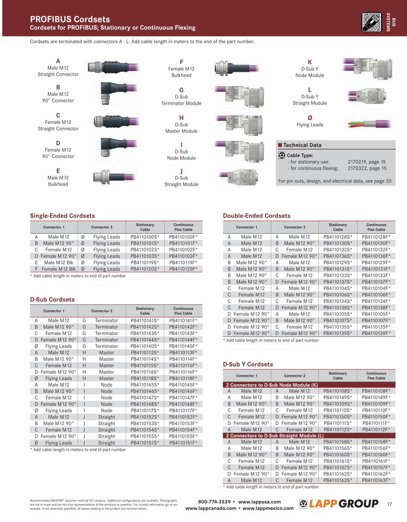
SYSTEMSCordsets for PROFIBUS; Stationary or Continuous FlexingPROFIBUS Cordsets
Technical Data
Cable Type: - for stationary use: 2170219, page 15 - for continuous flexing: 2170322, page 15
For pin outs, design, and electrical data, see page 20
AMale M12
Straight Connector
BMale M12
90° Connector
FFemale M12
Bulkhead
JD-Sub
Straight Module
CFemale M12
Straight Connector
DFemale M12
90° Connector
ØFlying Leads
EMale M12Bulkhead
ID-Sub
Node Module
GD-Sub
Terminator Module
KD-Sub Y
Node Module
HD-Sub
Master Module
LD-Sub Y
Straight Module
Cordsets are terminated with connectors A - L. Add cable length in meters to the end of the part number.
Single-Ended Cordsets
D-Sub Cordsets
* Add cable length in meters to end of part number
* Add cable length in meters to end of part number
* Add cable length in meters to end of part number
* Add cable length in meters to end of part number
Double-Ended Cordsets
D-Sub Y Cordsets
Connector 1 Connector 2 Stationary Cable
Continuous Flex Cable
A Male M12 Ø Flying Leads PB4110100S* PB4110100F*B Male M12 90° Ø Flying Leads PB4110101S* PB4110101F*C Female M12 Ø Flying Leads PB4110102S* PB4110102F*D Female M12 90° Ø Flying Leads PB4110103S* PB4110103F*E Male M12 Blk Ø Flying Leads PB4110119S* PB4110119F*F Female M12 Blk Ø Flying Leads PB4110120S* PB4110120F*
Connector 1 Connector 2 Stationary Cable
Continuous Flex Cable
A Male M12 G Terminator PB4110141S* PB4110141F*B Male M12 90° G Terminator PB4110142S* PB4110142F*C Female M12 G Terminator PB4110143S* PB4110143F*D Female M12 90° G Terminator PB4110144S* PB4110144F*Ø Flying Leads G Terminator PB4110140S* PB4110140F*A Male M12 H Master PB4110113S* PB4110113F*B Male M12 90° H Master PB4110114S* PB4110114F*C Female M12 H Master PB4110115S* PB4110115F*D Female M12 90° H Master PB4110116S* PB4110116F*Ø Flying Leads H Master PB4110118S* PB4110118F*A Male M12 I Node PB4110145S* PB4110145F*B Male M12 90° I Node PB4110146S* PB4110146F*C Female M12 I Node PB4110147S* PB4110147F*D Female M12 90° I Node PB4110148S* PB4110148F*Ø Flying Leads I Node PB4110117S* PB4110117F*A Male M12 J Straight PB4110152S* PB4110152F*B Male M12 90° J Straight PB4110153S* PB4110153F*C Female M12 J Straight PB4110154S* PB4110154F*D Female M12 90° J Straight PB4110155S* PB4110155F*Ø Flying Leads J Straight PB4110151S* PB4110151F*
Connector 1 Connector 2 Stationary Cable
Continuous Flex Cable
A Male M12 A Male M12 PB4110128S* PB4110128F*A Male M12 B Male M12 90° PB4110130S* PB4110130F*A Male M12 C Female M12 PB4110132S* PB4110132F*A Male M12 D Female M12 90° PB4110136S* PB4110136F*B Male M12 90° A Male M12 PB4110129S* PB4110129F*B Male M12 90° B Male M12 90° PB4110131S* PB4110131F*B Male M12 90° C Female M12 PB4110133S* PB4110133F*B Male M12 90° D Female M12 90° PB4110137S* PB4110137F*C Female M12 A Male M12 PB4110104S* PB4110104F*C Female M12 B Male M12 90° PB4110106S* PB4110106F*C Female M12 C Female M12 PB4110134S* PB4110134F*C Female M12 D Female M12 90° PB4110138S* PB4110138F*D Female M12 90° A Male M12 PB4110105S* PB4110105F*D Female M12 90° B Male M12 90° PB4110107S* PB4110107F*D Female M12 90° C Female M12 PB4110135S* PB4110135F*D Female M12 90° D Female M12 90° PB4110139S* PB4110139F*
Connector 1 Connector 2 Stationary Cable
Continuous Flex Cable
2 Connectors to D-Sub Node Module (K)A Male M12 A Male M12 PB4110108S* PB4110108F*A Male M12 B Male M12 90° PB4110149S* PB4110149F*B Male M12 90° B Male M12 90° PB4110109S* PB4110109F*C Female M12 C Female M12 PB4110110S* PB4110110F*C Female M12 D Female M12 90° PB4110150S* PB4110150F*D Female M12 90° D Female M12 90° PB4110111S* PB4110111F*A Male M12 C Female M12 PB4110112S* PB4110112F*
2 Connectors to D-Sub Straight Module (L)A Male M12 A Male M12 PB4110158S* PB4110158F*A Male M12 B Male M12 90° PB4110156S* PB4110156F*B Male M12 90° B Male M12 90° PB4110160S* PB4110160F*C Female M12 C Female M12 PB4110161S* PB4110161F*C Female M12 D Female M12 90° PB4110157S* PB4110157F*D Female M12 90° D Female M12 90° PB4110162S* PB4110162F*A Male M12 C Female M12 PB4110163S* PB4110163F*
800-774-3539 • www.lappusa.comwww.lappcanada.com • www.lappmexico.com
18Recommended SKINTOP® assumes minimal OD variance. Additional configurations are available. Photographs are not to scale and are not true representations of the products in question. For current information go to our website. If not otherwise specified, all values relating to the product are nominal values.
BUS
SYST
EMS
Construction
BUS
SYST
EMS
Construction
Technical Data
Minimum Bend Radius: 15 x cable diameter
Temperature Range: - for installation: -40°C to +80°C - for continuous flexing: -30°C to +70°C
Nominal Voltage: 250V
Impedance: 120 Ω ± 15%
Nominal Capacitance: 18 pF/ft
Color Code: DIN 47100: Chart 8, page 76 - Pair 1: White & brown - Pair 2: Green & yellow
Approvals: UL: CMX Canada: c(UL) CMX
Construction: 7-wire strands of bare copperInsulation: PolyethyleneShielding: Tinned copper braid shieldJacket: Violet halogen-free polyurethane
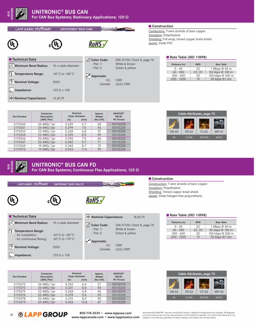
For CAN Bus Systems; Continuous Flex Applications; 120 ΩUNITRONIC® BUS CAN FD
Technical Data
Minimum Bend Radius: 10 x cable diameter
Temperature Range: -30°C to +80°C
Nominal Voltage: 250V
Impedance: 120 Ω ± 15%
Nominal Capacitance: 12 pF/ft
Color Code: DIN 47100: Chart 8, page 76 - Pair 1: White & brown - Pair 2: Green & yellow
Approvals: UL: CMX Canada: c(UL) CMX
Conductors: 7-wire strands of bare copperInsulation: PolyethyleneShielding: Foil wrap; tinned copper braid shieldJacket: Violet PVC
For CAN Bus Systems; Stationary Applications; 120 ΩUNITRONIC® BUS CAN
Part NumberConductor Description(AWG/Pair)
Nominal Outer Diameter
Approx. Weight
(lbs/mft)
SKINTOP® MS-SC
PG Thread(in) (mm)
2170260 24 AWG/1pr 0.224 5.7 28 531122202170261 24 AWG/2pr 0.299 7.6 46 531122202170263 22 AWG/1pr 0.268 6.8 37 531122202170264 22 AWG/2pr 0.335 8.5 59 531122202170266 20 AWG/1pr 0.296 7.5 60 531122202170267 20 AWG/2pr 0.382 9.7 71 531122302170269 19 AWG/1pr 0.343 8.7 73 531122202170270 19 AWG/2pr 0.453 11.5 95 53112230
Distance (m) AWG Max. Rate
0 - 40 22 1 Mbps @ 40 m40 - 300 22, 20 50 kbps @ 100 m
300 - 600 20 100 kbps @ 500 m600 - 1000 19 50 kbps @1 km
Rate Table (ISO 11898)
Distance (m) AWG Max. Rate
0 - 40 22 1 Mbps @ 40 m40 - 300 22, 20 50 kbps @ 100 m
300 - 600 20 100 kbps @ 500 m600 - 1000 19 50 kbps @1 km
Rate Table (ISO 11898)
Part NumberConductor Description(AWG/Pair)
Nominal Outer Diameter
Approx. Weight
(lbs/mft)
SKINTOP® MS-SC
PG Thread(in) (mm)
2170272 24 AWG/1pr 0.252 6.4 27 531122102170273 24 AWG/2pr 0.331 8.4 44 531122202170275 22 AWG/1pr 0.268 6.8 40 531122102170276 22 AWG/2pr 0.378 9.6 59 531122302170278 20 AWG/1pr 0.315 8.0 50 531122202170279 20 AWG/2pr 0.426 10.8 67 53112230
Cable Attributes, page 73
OR-00 FR-02 FL-02 MP-01
OIL FLAME MOTION MECH
Cable Attributes, page 73
OR-04 FR-02 CF-02 MP-05
OIL FLAME MOTION MECH
800-774-3539 • www.lappusa.comwww.lappcanada.com • www.lappmexico.com
19Recommended SKINTOP® assumes minimal OD variance. Additional configurations are available. Photographs are not to scale and are not true representations of the products in question. For current information go to our website. If not otherwise specified, all values relating to the product are nominal values.
BUS
SYSTEMS
Construction
BUS
SYSTEMS
Technical Data
Minimum Bend Radius: - for stationary use: 5 x cable diameter - for continuous flexing: 10 x cable diameter
Temperature Range: - for stationary use: -40°C to +80°C - for flexible use: -15°C to +80°C
Nominal Voltage: 300V
Color Code: - 3 conductors: 1: Brown, 2: Blue, 3: Black - 4 conductors: 1: Brown, 2: White, 3: Blue,
4: Black - 5 conductors: 1: Brown, 2: White, 3: Blue,
4: Black, 5: Gray - 8 conductors: 1: White, 2: Brown,
3: Green, 4: Yellow, 5: Gray, 6: Pink, 7: Blue, 8: Red
Approvals: UL: AWM 20549 Additional: RoHS
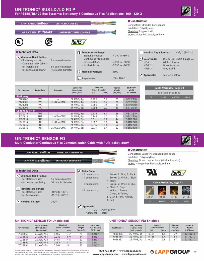
Conductors: Super fine stranded bare copperInsulation: PolypropyleneShielding: Tinned copper braid (shielded version)Jacket: Halogen-free black polyurethane
Multi-Conductor Continuous Flex Communication Cable with PUR Jacket; 300VUNITRONIC® SENSOR FD
Technical Data
Conductors: Stranded bare copperInsulation: PolyethyleneShielding: Copper braidJacket: Violet PVC or polyurethane
Minimum Bend Radius: - Stationary cables: 8 x cable diameter - Continuous flex cables: - for installation: 6 x cable diameter - for continuous flexing: 15 x cable diameter
Temperature Range: - Stationary cables: -40°C to +80°C - Continuous flex cables: - for installation: -40°C to +80°C - for flexible use: -30°C to +70°C
Nominal Voltage: 250V
Impedance: 100 - 120 Ω
Nominal Capacitance: 18 pF/ft (800 Hz)
Color Code: DIN 47100: Chart 8, page 76 - Pair 1: White & brown - Pair 2: Green & yellow - Pair 3: Gray & pink
Approvals: see table below
For RS485/RS422 Bus Systems; Stationary & Continuous Flex Applications; 100 - 120 ΩUNITRONIC® BUS LD/LD FD P
Cable Attributes, page 73
OR-04 FR-01 CF-02 MP-05
OIL FLAME MOTION MECH
Part NumberSize / Number of Conductors(incl. ground)
Nominal Outer Diameter
Approx. Weight
SKINTOP® Non-Metallic
PG Thread(in) (mm) (lbs/mft)
7038867 24 AWG/5c 0.185 4.7 23 S21077038868 24 AWG/8c 0.232 5.9 34 S21077038864 22 AWG/3c 0.181 4.6 20 S21077038865 22 AWG/4c 0.185 4.7 27 S21077038866 22 AWG/5c 0.201 5.1 30 S2107
Part NumberSize / Number of Conductors(incl. ground)
Nominal Outer Diameter
Approx. Weight
SKINTOP® MS-SC
PG Thread(in) (mm) (lbs/mft)
7038885 22 AWG/3c 0.181 4.6 79 531122107038886 22 AWG/4c 0.185 4.7 88 531122107038887 22 AWG/5c 0.201 5.1 97 53112210
Part Number Jacket Type ApprovalsConductor Description(AWG/Pair)
Nominal Outer Diameter
Approx. Weight
(lbs/mft)
SKINTOP® MS-SC
PG Thread(in) (mm)
Stationary2170203 PVC — 24 AWG/1pr 0.225 5.7 25 531122102170803 PVC UL/CSA CMX 24 AWG/1pr 0.225 5.7 26 531122102170204 PVC — 24 AWG/2pr 0.280 7.1 30 531122102170205 PVC — 24 AWG/3pr 0.284 7.2 48 53112210
Continuous Flex2170213 PUR — 24 AWG/1pr 0.236 6.0 26 531122102170813 PUR UL/CSA CMX 24 AWG/1pr 0.244 6.2 26 531122102170214 PUR — 24 AWG/2pr 0.311 7.9 44 531122202170814 PUR UL/CSA CMX 24 AWG/2pr 0.327 8.3 44 531122202170215 PUR — 24 AWG/3pr 0.315 8.0 52 531122202170815 PUR UL/CSA CMX 24 AWG/3pr 0.331 8.4 52 53112220
Construction
Cable Attributes, page 73
see table on page 10
OIL FLAME MOTION MECH
UNITRONIC® SENSOR FD: Unshielded UNITRONIC® SENSOR FD: Shielded
800-774-3539 • www.lappusa.comwww.lappcanada.com • www.lappmexico.com
20Recommended SKINTOP® assumes minimal OD variance. Additional configurations are available. Photographs are not to scale and are not true representations of the products in question. For current information go to our website. If not otherwise specified, all values relating to the product are nominal values.
BUS
SYST
EMS
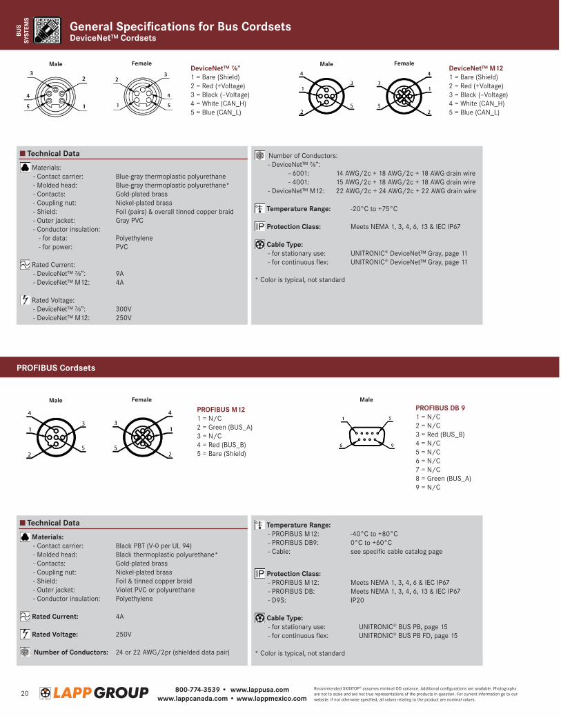
DeviceNet™ CordsetsGeneral Specifications for Bus Cordsets
PROFIBUS M121 = N/C2 = Green (BUS_A)3 = N/C4 = Red (BUS_B)5 = Bare (Shield)
DeviceNet™ ⅞”1 = Bare (Shield)2 = Red (+Voltage)3 = Black (–Voltage)4 = White (CAN_H)5 = Blue (CAN_L)
Male
Male Male
Female
Female Female
PROFIBUS DB 91 = N/C 2 = N/C 3 = Red (BUS_B) 4 = N/C 5 = N/C6 = N/C7 = N/C8 = Green (BUS_A)9 = N/C
DeviceNet™ M121 = Bare (Shield)2 = Red (+Voltage)3 = Black (–Voltage)4 = White (CAN_H)5 = Blue (CAN_L)
Male
Technical Data
Technical Data
Materials: - Contact carrier: Black PBT (V-0 per UL 94) - Molded head: Black thermoplastic polyurethane* - Contacts: Gold-plated brass - Coupling nut: Nickel-plated brass - Shield: Foil & tinned copper braid - Outer jacket: Violet PVC or polyurethane - Conductor insulation: Polyethylene
Rated Current: 4A
Rated Voltage: 250V
Number of Conductors: 24 or 22 AWG/2pr (shielded data pair)
Materials: - Contact carrier: Blue-gray thermoplastic polyurethane - Molded head: Blue-gray thermoplastic polyurethane* - Contacts: Gold-plated brass - Coupling nut: Nickel-plated brass - Shield: Foil (pairs) & overall tinned copper braid - Outer jacket: Gray PVC - Conductor insulation: - for data: Polyethylene - for power: PVC
Rated Current: - DeviceNet™ ⅞”: 9A - DeviceNet™ M12: 4A
Rated Voltage: - DeviceNet™ ⅞”: 300V - DeviceNet™ M12: 250V
Temperature Range: - PROFIBUS M12: -40°C to +80°C - PROFIBUS DB9: 0°C to +60°C - Cable: see specific cable catalog page
Protection Class: - PROFIBUS M12: Meets NEMA 1, 3, 4, 6 & IEC IP67 - PROFIBUS DB: Meets NEMA 1, 3, 4, 6, 13 & IEC IP67 - D9S: IP20
Cable Type: - for stationary use: UNITRONIC® BUS PB, page 15 - for continuous flex: UNITRONIC® BUS PB FD, page 15
* Color is typical, not standard
Number of Conductors: - DeviceNet™ ⅞”: - 6001: 14 AWG/2c + 18 AWG/2c + 18 AWG drain wire - 4001: 15 AWG/2c + 18 AWG/2c + 18 AWG drain wire - DeviceNet™ M12: 22 AWG/2c + 24 AWG/2c + 22 AWG drain wire
Temperature Range: -20°C to +75°C
Protection Class: Meets NEMA 1, 3, 4, 6, 13 & IEC IP67
Cable Type: - for stationary use: UNITRONIC® DeviceNet™ Gray, page 11 - for continuous flex: UNITRONIC® DeviceNet™ Gray, page 11
* Color is typical, not standard
PROFIBUS Cordsets
800-774-3539 • www.lappusa.comwww.lappcanada.com • www.lappmexico.com
21Recommended SKINTOP® assumes minimal OD variance. Additional configurations are available. Photographs are not to scale and are not true representations of the products in question. For current information go to our website. If not otherwise specified, all values relating to the product are nominal values.
BUS
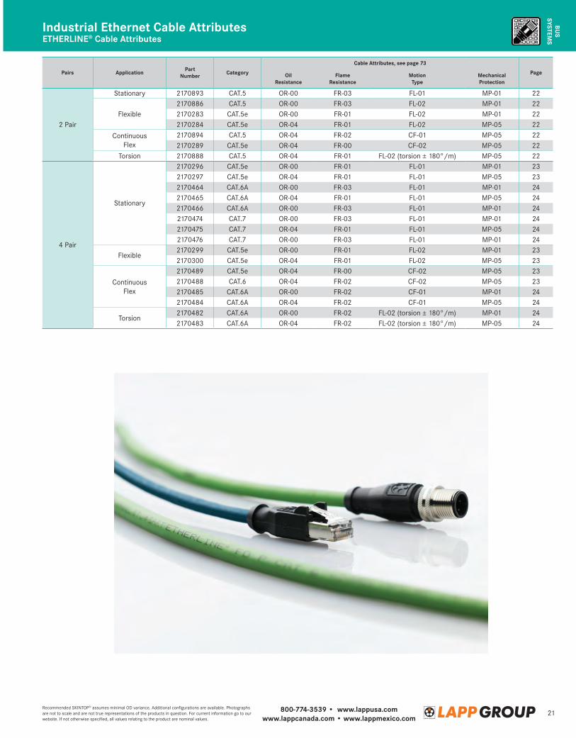
SYSTEMSIndustrial Ethernet Cable AttributesETHERLINE® Cable Attributes
Pairs Application Part Number Category
Cable Attributes, see page 73
PageOil Resistance
Flame Resistance
MotionType
Mechanical Protection
2 Pair
Stationary 2170893 CAT.5 OR-00 FR-03 FL-01 MP-01 22
Flexible2170886 CAT.5 OR-00 FR-03 FL-02 MP-01 222170283 CAT.5e OR-00 FR-01 FL-02 MP-01 222170284 CAT.5e OR-04 FR-01 FL-02 MP-05 22
ContinuousFlex
2170894 CAT.5 OR-04 FR-02 CF-01 MP-05 222170289 CAT.5e OR-04 FR-00 CF-02 MP-05 22
Torsion 2170888 CAT.5 OR-04 FR-01 FL-02 (torsion ± 180°/m) MP-05 22
4 Pair
Stationary
2170296 CAT.5e OR-00 FR-01 FL-01 MP-01 232170297 CAT.5e OR-04 FR-01 FL-01 MP-05 232170464 CAT.6A OR-00 FR-03 FL-01 MP-01 242170465 CAT.6A OR-04 FR-01 FL-01 MP-05 242170466 CAT.6A OR-00 FR-03 FL-01 MP-01 242170474 CAT.7 OR-00 FR-03 FL-01 MP-01 242170475 CAT.7 OR-04 FR-01 FL-01 MP-05 242170476 CAT.7 OR-00 FR-03 FL-01 MP-01 24
Flexible2170299 CAT.5e OR-00 FR-01 FL-02 MP-01 232170300 CAT.5e OR-04 FR-01 FL-02 MP-05 23
ContinuousFlex
2170489 CAT.5e OR-04 FR-00 CF-02 MP-05 232170488 CAT.6 OR-04 FR-02 CF-02 MP-05 232170485 CAT.6A OR-00 FR-02 CF-01 MP-01 242170484 CAT.6A OR-04 FR-02 CF-01 MP-05 24
Torsion2170482 CAT.6A OR-00 FR-02 FL-02 (torsion ± 180°/m) MP-01 242170483 CAT.6A OR-04 FR-02 FL-02 (torsion ± 180°/m) MP-05 24

800-774-3539 • www.lappusa.comwww.lappcanada.com • www.lappmexico.com
22Recommended SKINTOP® assumes minimal OD variance. Additional configurations are available. Photographs are not to scale and are not true representations of the products in question. For current information go to our website. If not otherwise specified, all values relating to the product are nominal values.
BUS
SYST
EMS
Technical Data
Construction
Technical Data
Conductors: Stranded tinned copperPairs: Star quadInsulation: Foamed polyethyleneShielding: Tinned copper braid; non-woven wrapJacket: Green halogen-free polyurethane
Minimum Bend Radius: 5 x cable diameter
Temperature Range: -40°C to +80°C
Nominal Voltage: 100V (not for power)
Impedance: 100Ω ± 15Ω
Color Code: White, yellow, blue, orange
Approvals: UL: AWM 21161 Additional: RoHS
Industrial Ethernet Cable Suitable for Torsion StressETHERLINE® 2 Pair: CAT.5 TORSION
Conductors: Solid or stranded bare copperPairs: Two twisted pairs or star quadInsulation: PolyethyleneShielding: Foil and braid (2170289: braid only)Jacket: Green or teal PVC, polyurethane, or halogen-free
Minimum Bend Radius: - for stationary use: 10 x cable diameter - for flexible use: 15 x cable diameter - for continuous flexing: 15 x cable diameter
Temperature Range: - for stationary use: -40°C to +80°C - for flexible use: - CAT.5 cable: -20°C to +60°C - CAT.5e cable: -5°C to +60°C - for continuous flexing: -20°C to +60°C
Nominal Voltage: see table below
Impedance: 100Ω ± 15Ω
Color Code: - CAT.5 cable: White, yellow, blue, orange - CAT.5e cable: White/orange & orange,
white/green & green
Approvals: see table below
Industrial Ethernet Cables for Stationary, Flexing & Continuous Flex ApplicationsETHERLINE® 2 Pair: CAT.5/5e
Part Number Size / Pairs Stranding Jacket Category
Nominal Voltage
(not for power)Approvals Fast
Connect
Nominal Outer Diameter
Approx. Weight
(lbs/mft)
SKINTOP® MS-SC
PG Thread(in) (mm)
Stationary
2170893 22 AWG/2pr Solid Green PVC CAT.5 600V PROFINET, UL AWM, UL/CSA CMG, 600V
Yes 0.256 6.5 47 53112210
Flexing
2170886 22 AWG/2pr 7 wire Green PVC CAT.5 600V PROFINET, UL AWM,UL/CSA CMG, 600V
Yes 0.256 6.5 45 53112210
2170283* 26 AWG/2pr 7 wire Teal HF CAT.5e 125V — No 0.213 5.4 29 531122102170284* 26 AWG/2pr 7 wire Teal PUR CAT.5e 125V UL/CSA AWM No 0.228 5.8 30 53112210Continuous Flex2170894 22 AWG/2pr 7 wire Green PUR CAT.5 100V PROFINET, UL/CSA CMX Yes 0.256 6.5 42 53112210
2170289* 26 AWG/2pr 19 wire Teal PUR CAT.5e 125V UL/CSA AWM No 0.240 6.1 32 53112210* Max cable run: 196 ft (60 m)
Part Number Size / Pairs Stranding Jacket Approvals Fast
Connect
Nominal Outer Diameter
Approx. Weight
(lbs/mft)
SKINTOP® MS-SC
PG Thread(in) (mm)
2170888 22 AWG/2pr 19 wire Green PUR PROFINET, UL AWM No 0.256 6.5 35 53112210
Cable Attributes, page 73
OR-04 FR-01 FL-02* MP-05
OIL FLAME MOTION MECH
* Torsion ±180°/m
Cable Attributes, page 73
see table on page 21
OIL FLAME MOTION MECH
BUS
SYST
EMS
Construction
800-774-3539 • www.lappusa.comwww.lappcanada.com • www.lappmexico.com
23Recommended SKINTOP® assumes minimal OD variance. Additional configurations are available. Photographs are not to scale and are not true representations of the products in question. For current information go to our website. If not otherwise specified, all values relating to the product are nominal values.
BUS
SYSTEMS
Construction
Technical Data
BUS
SYSTEMS
Construction
Technical Data
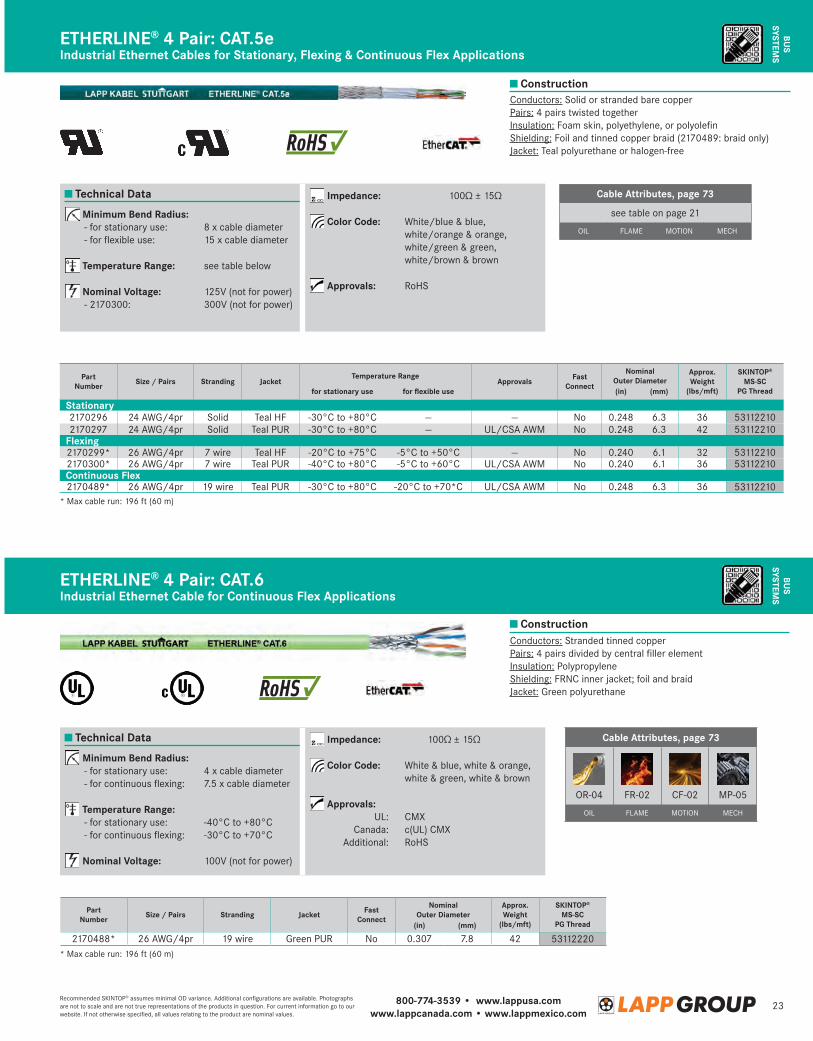
Minimum Bend Radius: - for stationary use: 4 x cable diameter -forcontinuousflexing: 7.5xcablediameter
Temperature Range: - for stationary use: -40°C to +80°C -forcontinuousflexing: -30°Cto+70°C
Nominal Voltage: 100V (not for power)
Impedance: 100Ω±15Ω
Color Code: White&blue,white&orange, white&green,white&brown
Approvals: UL: CMX Canada: c(UL) CMX Additional: RoHS
Conductors: Stranded tinned copperPairs:4pairsdividedbycentralfillerelementInsulation: PolypropyleneShielding: FRNC inner jacket; foil and braidJacket: Green polyurethane
Industrial Ethernet Cable for Continuous Flex ApplicationsETHERLINE® 4 Pair: CAT.6
ETHERLINE® 4 Pair: CAT.5eIndustrial Ethernet Cables for Stationary, Flexing & Continuous Flex Applications
Conductors: Solid or stranded bare copperPairs:4pairstwistedtogetherInsulation:Foamskin,polyethylene,orpolyolefinShielding:Foilandtinnedcopperbraid(2170489:braidonly)Jacket:Tealpolyurethaneorhalogen-free
Minimum Bend Radius: - for stationary use: 8 x cable diameter -forflexibleuse: 15xcablediameter
Temperature Range: see table below
Nominal Voltage: 125V(notforpower) -2170300: 300V(notforpower)
Impedance: 100Ω±15Ω
Color Code: White/blue & blue, white/orange&orange, white/green&green, white/brown & brown
Approvals: RoHS
Part Number Size / Pairs Stranding Jacket
Temperature RangeApprovals Fast
Connect
Nominal Outer Diameter
Approx. Weight
(lbs/mft)
SKINTOP® MS-SC
PG Threadfor stationary use for flexible use (in) (mm)
Stationary2170296 24 AWG/4pr Solid Teal HF -30°C to +80°C — — No 0.248 6.3 36 531122102170297 24 AWG/4pr Solid Teal PUR -30°C to +80°C — UL/CSA AWM No 0.248 6.3 42 53112210
Flexing2170299* 26AWG/4pr 7wire Teal HF -20°Cto+75°C -5°Cto+50°C — No 0.240 6.1 32 531122102170300* 26AWG/4pr 7wire Teal PUR -40°C to +80°C -5°Cto+60°C UL/CSA AWM No 0.240 6.1 36 53112210Continuous Flex2170489* 26AWG/4pr 19wire Teal PUR -30°C to +80°C -20°Cto+70*C UL/CSA AWM No 0.248 6.3 36 53112210
*Maxcablerun:196ft(60m)
*Maxcablerun:196ft(60m)
Cable Attributes, page 73
OR-04 FR-02 CF-02 MP-05
OIL FLAME MOTION MECH
Part Number Size / Pairs Stranding Jacket Fast
Connect
Nominal Outer Diameter
Approx. Weight
(lbs/mft)
SKINTOP® MS-SC
PG Thread(in) (mm)
2170488* 26AWG/4pr 19wire Green PUR No 0.307 7.8 42 53112220
Cable Attributes, page 73
seetableonpage21
OIL FLAME MOTION MECH

800-774-3539 • www.lappusa.comwww.lappcanada.com • www.lappmexico.com
24Recommended SKINTOP® assumes minimal OD variance. Additional configurations are available. Photographs are not to scale and are not true representations of the products in question. For current information go to our website. If not otherwise specified, all values relating to the product are nominal values.
BUS
SYST
EMS
Construction
Construction
Construction
BUS
SYST
EMS
BUS
SYST
EMS
ETHERLINE® 4 Pair: CAT.6A; Continuous Flex
ETHERLINE® 4 Pair: CAT.6A TORSION
Industrial Ethernet Cable for Continuous Flex Applications
Industrial Ethernet Cable for Torsion Stress
Technical Data
Technical Data
Technical Data
Conductors: Solid bare copperPairs: 4 pairs, individually shielded with foil tapeInsulation: PolyethyleneShielding: Overall copper braidJacket: Green PVC, polyurethane, or halogen-free
Conductors: Stranded tinned copperPairs: 4 pairs individually shielded with aluminum
compound foilInsulation: Foam skinShielding: Foil-laminated fleece and tinned copper
braidJacket: Green PVC or polyurethane
Conductors: Stranded tinned copperPairs: 4 pairs individually shielded with aluminum
compound foilInsulation: Foam skinShielding: Foil-laminated fleece and tinned copper
braidJacket: Green PVC or polyurethane
Minimum Bend Radius: - for stationary use: 10 x cable diameter
Temperature Range: - PUR & PVC: -40°C to +80°C - Halogen-free: -25°C to +80°C
Minimum Bend Radius: - for continuous flexing: 15 x cable diameter
Temperature Range: - for stationary use: -40°C to +80°C - for continuous flexing: -10°C to +70°C
Minimum Bend Radius: 15 x cable diameter
Temperature Range: - for stationary use: -40°C to +80°C - for flexible use: -10°C to +70°C
Nominal Voltage: 100V (not for power)
Impedance: 100Ω ± 15Ω
Color Code: White/blue & blue, white/orange & orange, white/green & green, white/brown & brown
Nominal Voltage: 125V (not for power)
Impedance: 100Ω ± 15Ω
Color Code: White/blue & blue, white/orange & orange, white/green & green, white/brown & brown
Nominal Voltage: 125V (not for power)
Impedance: 100Ω ± 15Ω
Color Code: White/blue & blue, white/orange & orange, white/green & green, white/brown & brown
Industrial Ethernet Cable for Stationary ApplicationsETHERLINE® 4 Pair: CAT.6A/7; Stationary
Part Number Size / Pairs Stranding Jacket Category Fast
Connect
Nominal Outer Diameter
Approx. Weight
SKINTOP® MS-SC
PG Thread(in) (mm) (lbs/mft)
2170464 22 AWG/4pr Solid Green PVC CAT.6A No 0.343 8.7 66 531122202170465 22 AWG/4pr Solid Green PUR CAT.6A No 0.343 8.7 61 531122202170466 22 AWG/4pr Solid Green HF CAT.6A No 0.343 8.7 67 531122202170474 22 AWG/4pr Solid Green PVC CAT.7 No 0.343 8.7 66 531122202170475 22 AWG/4pr Solid Green PUR CAT.7 No 0.343 8.7 61 531122202170476 22 AWG/4pr Solid Green HF CAT.7 No 0.343 8.7 67 53112220
Part Number Size / Pairs Stranding Jacket Category Approvals Fast
Connect
Nominal Outer Diameter
Approx. Weight
SKINTOP® MS-SC
PG Thread(in) (mm) (lbs/mft)
2170485 24 AWG/4pr 7 wire Green PVC CAT.6A PROFINET No 0.355 9.0 59 531122202170484 24 AWG/4pr 7 wire Green PVC CAT.6A UL/CSA AWM, PROFINET No 0.355 9.0 60 53112220
Part Number Size / Pairs Stranding Jacket Category Approvals Fast
Connect
Nominal Outer Diameter
Approx. Weight
(lbs/mft)
SKINTOP® MS-SC
PG Thread(in) (mm)
2170482 24 AWG/4pr 7 wire Green PVC CAT.6A PROFINET No 0.355 9.0 59 531122202170483 24 AWG/4pr 7 wire Green PUR CAT.6A UL/CSA AWM, PROFINET No 0.355 9.0 60 53112220
800-774-3539 • www.lappusa.comwww.lappcanada.com • www.lappmexico.com
25Recommended SKINTOP® assumes minimal OD variance. Additional configurations are available. Photographs are not to scale and are not true representations of the products in question. For current information go to our website. If not otherwise specified, all values relating to the product are nominal values.
BUS
SYSTEMS
BUS
SYSTEMS
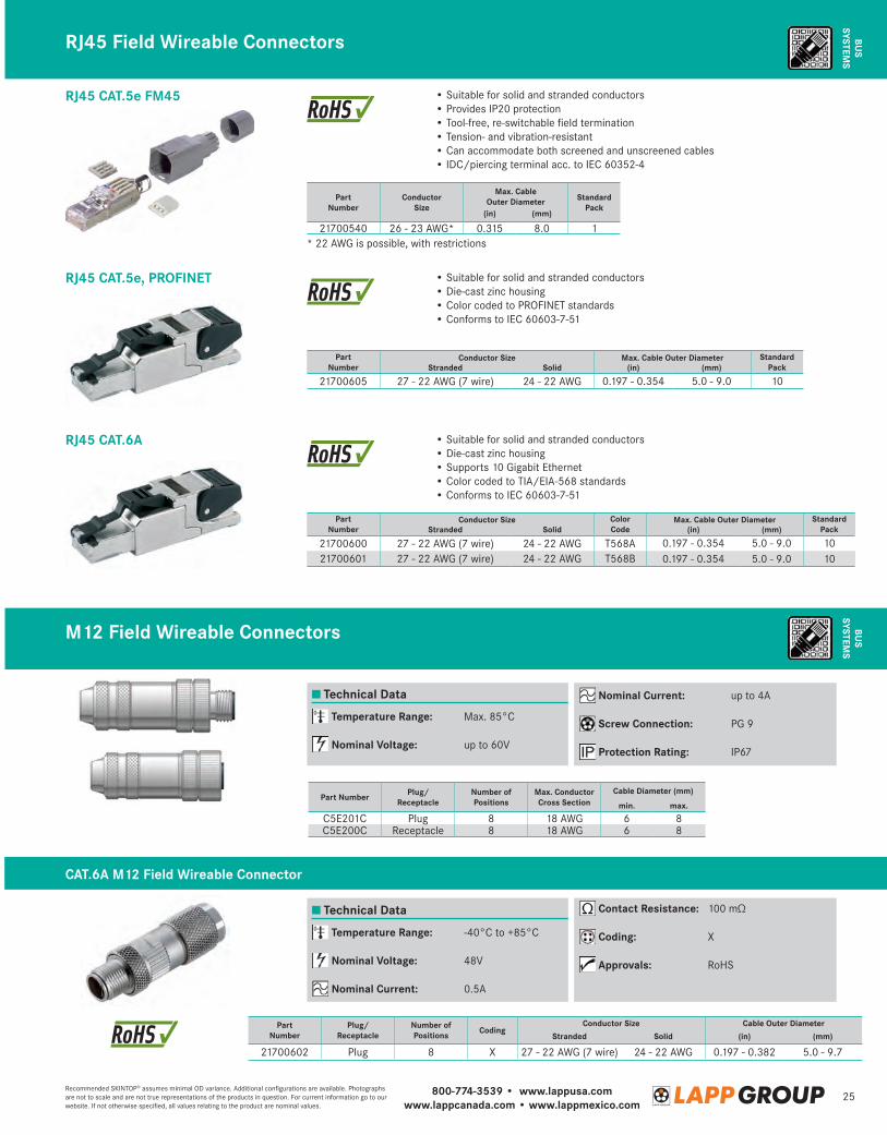
M12 Field Wireable Connectors
RJ45 Field Wireable Connectors
RJ45 CAT.5e FM45
RJ45 CAT.5e, PROFINET
RJ45 CAT.6A
Part Number
ConductorSize
Max. Cable Outer Diameter Standard
Pack(in) (mm)
21700540 26 - 23 AWG* 0.315 8.0 1* 22 AWG is possible, with restrictions
• Suitable for solid and stranded conductors• Provides IP20 protection• Tool-free, re-switchable field termination• Tension- and vibration-resistant• Can accommodate both screened and unscreened cables• IDC/piercing terminal acc. to IEC 60352-4
• Suitable for solid and stranded conductors• Die-cast zinc housing• Color coded to PROFINET standards• Conforms to IEC 60603-7-51
• Suitable for solid and stranded conductors• Die-cast zinc housing• Supports 10 Gigabit Ethernet• Color coded to TIA/EIA-568 standards• Conforms to IEC 60603-7-51
Part Number
Conductor Size Max. Cable Outer Diameter Standard PackStranded Solid (in) (mm)
21700605 27 - 22 AWG (7 wire) 24 - 22 AWG 0.197 - 0.354 5.0 - 9.0 10
Part Number
Conductor Size Color Code
Max. Cable Outer Diameter Standard PackStranded Solid (in) (mm)
21700600 27 - 22 AWG (7 wire) 24 - 22 AWG T568A 0.197 - 0.354 5.0 - 9.0 1021700601 27 - 22 AWG (7 wire) 24 - 22 AWG T568B 0.197 - 0.354 5.0 - 9.0 10
Part Number
Plug/Receptacle
Number ofPositions Coding
Conductor Size Cable Outer DiameterStranded Solid (in) (mm)
21700602 Plug 8 X 27 - 22 AWG (7 wire) 24 - 22 AWG 0.197 - 0.382 5.0 - 9.7
Part Number Plug/Receptacle
Number of Positions
Max. Conductor Cross Section
Cable Diameter (mm)
min. max.
C5E201C Plug 8 18 AWG 6 8C5E200C Receptacle 8 18 AWG 6 8
Technical Data
Technical Data
Temperature Range: Max. 85°C
Nominal Voltage: up to 60V
Temperature Range: -40°C to +85°C
Nominal Voltage: 48V
Nominal Current: 0.5A
Nominal Current: up to 4A
Screw Connection: PG 9
Protection Rating: IP67
Contact Resistance: 100 mΩ
Coding: X
Approvals: RoHS
CAT.6A M12 Field Wireable Connector
800-774-3539 • www.lappusa.comwww.lappcanada.com • www.lappmexico.com
26Recommended SKINTOP® assumes minimal OD variance. Additional configurations are available. Photographs are not to scale and are not true representations of the products in question. For current information go to our website. If not otherwise specified, all values relating to the product are nominal values.
BUS
SYST
EMS
BUS
SYST
EMS
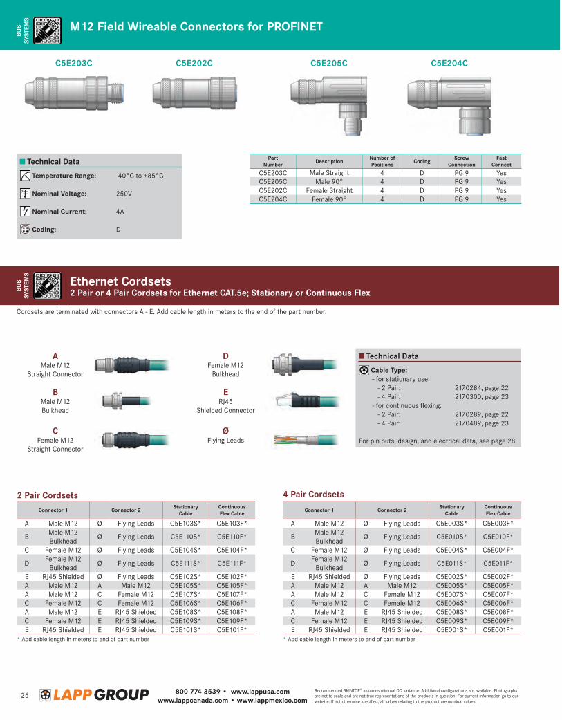
2 Pair or 4 Pair Cordsets for Ethernet CAT.5e; Stationary or Continuous FlexEthernet Cordsets
M12 Field Wireable Connectors for PROFINET
Part Number Description Number of
Positions Coding ScrewConnection
Fast Connect
C5E203C Male Straight 4 D PG 9 YesC5E205C Male 90° 4 D PG 9 YesC5E202C Female Straight 4 D PG 9 YesC5E204C Female 90° 4 D PG 9 Yes
Technical Data
Technical Data
Temperature Range: -40°C to +85°C
Nominal Voltage: 250V
Nominal Current: 4A
Coding: D
Cable Type: - for stationary use: - 2 Pair: 2170284, page 22 - 4 Pair: 2170300, page 23 - for continuous flexing: - 2 Pair: 2170289, page 22 - 4 Pair: 2170489, page 23
For pin outs, design, and electrical data, see page 28
AMale M12
Straight Connector
BMale M12 Bulkhead
ERJ45
Shielded Connector
CFemale M12
Straight Connector
DFemale M12
Bulkhead
ØFlying Leads
Connector 1 Connector 2 Stationary Cable
Continuous Flex Cable
A Male M12 Ø Flying Leads C5E003S* C5E003F*
BMale M12 Bulkhead
Ø Flying Leads C5E010S* C5E010F*
C Female M12 Ø Flying Leads C5E004S* C5E004F*
DFemale M12
BulkheadØ Flying Leads C5E011S* C5E011F*
E RJ45 Shielded Ø Flying Leads C5E002S* C5E002F*A Male M12 A Male M12 C5E005S* C5E005F*A Male M12 C Female M12 C5E007S* C5E007F*C Female M12 C Female M12 C5E006S* C5E006F*A Male M12 E RJ45 Shielded C5E008S* C5E008F*C Female M12 E RJ45 Shielded C5E009S* C5E009F*E RJ45 Shielded E RJ45 Shielded C5E001S* C5E001F*
Connector 1 Connector 2 Stationary Cable
Continuous Flex Cable
A Male M12 Ø Flying Leads C5E103S* C5E103F*
BMale M12 Bulkhead
Ø Flying Leads C5E110S* C5E110F*
C Female M12 Ø Flying Leads C5E104S* C5E104F*
DFemale M12
BulkheadØ Flying Leads C5E111S* C5E111F*
E RJ45 Shielded Ø Flying Leads C5E102S* C5E102F*A Male M12 A Male M12 C5E105S* C5E105F*A Male M12 C Female M12 C5E107S* C5E107F*C Female M12 C Female M12 C5E106S* C5E106F*A Male M12 E RJ45 Shielded C5E108S* C5E108F*C Female M12 E RJ45 Shielded C5E109S* C5E109F*E RJ45 Shielded E RJ45 Shielded C5E101S* C5E101F*
Cordsets are terminated with connectors A - E. Add cable length in meters to the end of the part number.
4 Pair Cordsets
* Add cable length in meters to end of part number* Add cable length in meters to end of part number
2 Pair Cordsets
C5E203C C5E205CC5E202C C5E204C
800-774-3539 • www.lappusa.comwww.lappcanada.com • www.lappmexico.com
27Recommended SKINTOP® assumes minimal OD variance. Additional configurations are available. Photographs are not to scale and are not true representations of the products in question. For current information go to our website. If not otherwise specified, all values relating to the product are nominal values.
BUS
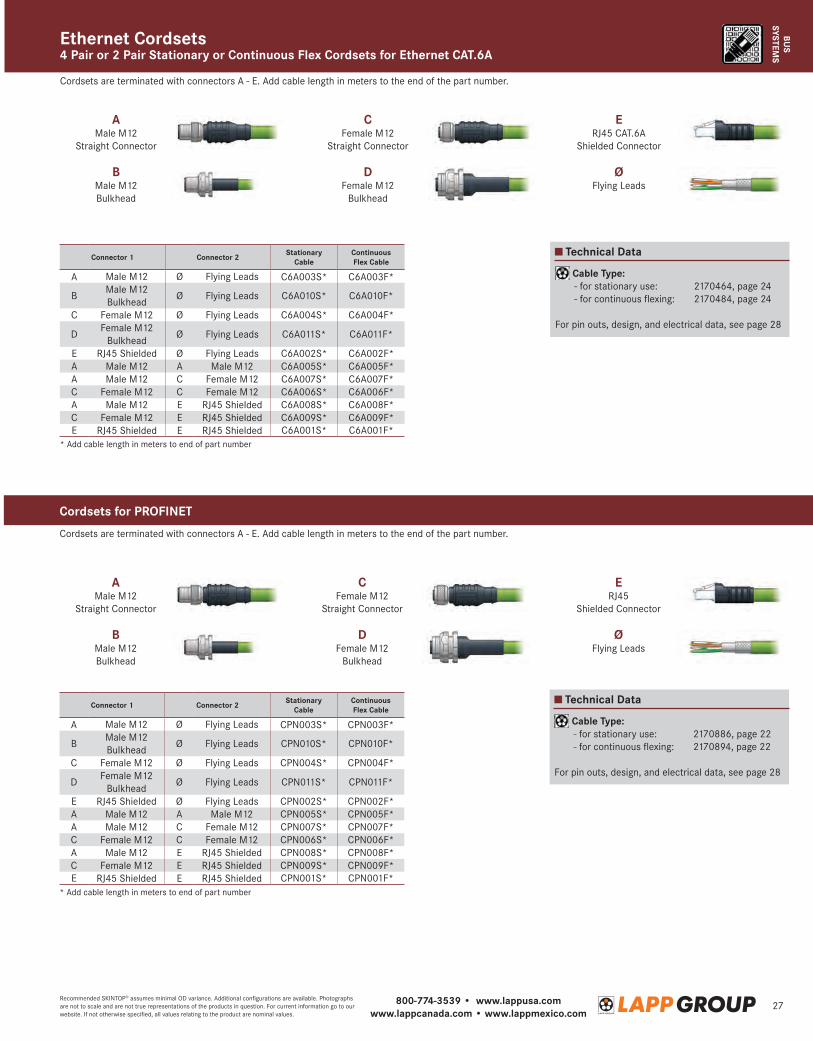
SYSTEMS4 Pair or 2 Pair Stationary or Continuous Flex Cordsets for Ethernet CAT.6AEthernet Cordsets
Technical Data
Cable Type: - for stationary use: 2170464, page 24 - for continuous flexing: 2170484, page 24
For pin outs, design, and electrical data, see page 28
AMale M12
Straight Connector
AMale M12
Straight Connector
CFemale M12
Straight Connector
CFemale M12
Straight Connector
DFemale M12
Bulkhead
DFemale M12
Bulkhead
ERJ45 CAT.6A
Shielded Connector
ERJ45
Shielded Connector
BMale M12 Bulkhead
BMale M12 Bulkhead
ØFlying Leads
ØFlying Leads
Connector 1 Connector 2 Stationary Cable
Continuous Flex Cable
A Male M12 Ø Flying Leads CPN003S* CPN003F*
BMale M12 Bulkhead
Ø Flying Leads CPN010S* CPN010F*
C Female M12 Ø Flying Leads CPN004S* CPN004F*
DFemale M12
BulkheadØ Flying Leads CPN011S* CPN011F*
E RJ45 Shielded Ø Flying Leads CPN002S* CPN002F*A Male M12 A Male M12 CPN005S* CPN005F*A Male M12 C Female M12 CPN007S* CPN007F*C Female M12 C Female M12 CPN006S* CPN006F*A Male M12 E RJ45 Shielded CPN008S* CPN008F*C Female M12 E RJ45 Shielded CPN009S* CPN009F*E RJ45 Shielded E RJ45 Shielded CPN001S* CPN001F*
Connector 1 Connector 2 Stationary Cable
Continuous Flex Cable
A Male M12 Ø Flying Leads C6A003S* C6A003F*
BMale M12 Bulkhead
Ø Flying Leads C6A010S* C6A010F*
C Female M12 Ø Flying Leads C6A004S* C6A004F*
DFemale M12
BulkheadØ Flying Leads C6A011S* C6A011F*
E RJ45 Shielded Ø Flying Leads C6A002S* C6A002F*A Male M12 A Male M12 C6A005S* C6A005F*A Male M12 C Female M12 C6A007S* C6A007F*C Female M12 C Female M12 C6A006S* C6A006F*A Male M12 E RJ45 Shielded C6A008S* C6A008F*C Female M12 E RJ45 Shielded C6A009S* C6A009F*E RJ45 Shielded E RJ45 Shielded C6A001S* C6A001F*
Cordsets are terminated with connectors A - E. Add cable length in meters to the end of the part number.
Cordsets are terminated with connectors A - E. Add cable length in meters to the end of the part number.
* Add cable length in meters to end of part number
* Add cable length in meters to end of part number
Cordsets for PROFINET
Technical Data
Cable Type: - for stationary use: 2170886, page 22 - for continuous flexing: 2170894, page 22
For pin outs, design, and electrical data, see page 28
800-774-3539 • www.lappusa.comwww.lappcanada.com • www.lappmexico.com
28Recommended SKINTOP® assumes minimal OD variance. Additional configurations are available. Photographs are not to scale and are not true representations of the products in question. For current information go to our website. If not otherwise specified, all values relating to the product are nominal values.
BUS
SYST
EMS
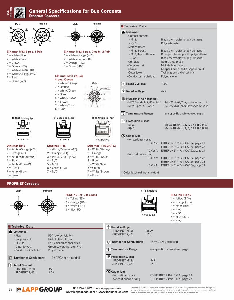
PROFINET M12 D-coded1 = Yellow (TD+)2 = Orange (TD - )3 = White (RD+)4 = Blue (RD - )
Ethernet M12 8-pos. 4 Pair1 = White/Blue2 = White/Brown3 = Brown4 = Orange (-TX)5 = White/Green (+RX)6 = White/Orange (+TX)7 = Blue8 = Green (-RX)
Ethernet M12 CAT.6A 8-pos. X-code1 = White/Orange2 = Orange3 = White/Green4 = Green5 = White/Brown6 = Brown7 = White/Blue8 = Blue
Male
Male
Male
Male
RJ45 Shielded, 4pr
Female
Female Female
RJ45 Shielded, 2pr RJ45 Shielded, 4pr
PROFINET RJ451 = Yellow (TD+)2 = Orange (TD - )3 = White (RD+)4 = N/C5 = N/C6 = Blue (RD - )7 = N/C
Ethernet M12 4-pos. D-code, 2 Pair1 = White/Orange (+TX)2 = White/Green (+RX)3 = Orange (–TX)4 = Green (–RX)
Ethernet RJ451 = White/Orange (+TX)2 = Orange (–TX)3 = White/Green (+RX)4 = Blue5 = White/Blue (-RX)6 = Green7 = White/Brown8 = Brown
Ethernet RJ451 = White/Orange (+TX)2 = Orange (–TX)3 = White/Green (+RX)4 = N/C5 = N/C6 = Green (–RX)7 = N/C
Ethernet RJ45 CAT.6A1 = White/Orange2 = Orange3 = White/Green4 = Blue5 = White/Blue6 = Green7 = White/Brown8 = Brown
RJ45 Shielded
Technical Data
Technical Data
Materials: - Plug: PBT (V-0 per UL 94) - Coupling nut: Nickel-plated brass - Shield: Foil & tinned copper braid - Outer jacket: Green polyurethane or PVC - Conductor insulation: Polyethylene
Number of Conductors: 22 AWG/2pr, stranded
Rated Current: - PROFINET M12: 4A - PROFINET RJ45: 1.5A
Materials: - Contact carrier: - M12: Black thermoplastic polyurethane - RJ45: Polycarbonate - Molded head: - M12, 8-pos.: Black thermoplastic polyurethane* - M12, 4-pos. D-code: Blue-gray thermoplastic polyurethane* - RJ45: Black thermoplastic polyurethane* - Contacts: Gold-plated brass - Coupling nut: Nickel-plated brass - Shield: Copper braid or foil & copper braid - Outer jacket: Teal or green polyurethane - Conductor insulation: Polyethylene
Rated Current: 1.5A
Rated Voltage: 42V
Number of Conductors: - M12 D-code & RJ45 shield: 26 - 22 AWG/2pr, stranded or solid - M12 8-pos. & RJ45S: 26 - 22 AWG/4pr, stranded or solid
Temperature Range: see specific cable catalog page
Protection Class: - M12: Meets NEMA 1, 3, 4, 6P & IEC IP67 - RJ45: Meets NEMA 1, 3, 4, 6P & IEC IP20
Cable Type: - for stationary use: CAT.5e: ETHERLINE® 2 Pair CAT.5e, page 22 ETHERLINE® 4 Pair CAT.5e, page 23 CAT.6A: ETHERLINE® 4 Pair CAT.6A, page 24 - for continuous flex: CAT.5e: ETHERLINE® 2 Pair CAT.5e, page 22 ETHERLINE® 4 Pair CAT.5e, page 23 CAT.6A: ETHERLINE® 4 Pair CAT.6A, page 24
* Color is typical, not standard
Rated Voltage: - PROFINET M12: 250V - PROFINET RJ45: 42V
Number of Conductors: 22 AWG/2pr, stranded
Temperature Range: see specific cable catalog page
Protection Class: - PROFINET M12: IP67 - PROFINET RJ45: IP20
Cable Type: - for stationary use: ETHERLINE® 2 Pair CAT.5, page 22 - for continuous flexing: ETHERLINE® 2 Pair CAT.5, page 22
PROFINET Cordsets
Ethernet CordsetsGeneral Specifications for Bus Cordsets

800-774-3539 • www.lappusa.comwww.lappcanada.com • www.lappmexico.com
29Recommended SKINTOP® assumes minimal OD variance. Additional configurations are available. Photographs are not to scale and are not true representations of the products in question. For current information go to our website. If not otherwise specified, all values relating to the product are nominal values.
ELECTRON
ICCA
BLE
Construction
Cable Attributes, page 73
OR-01 FR-03 FL-01 MP-01
OIL FLAME MOTION MECH
Technical Data
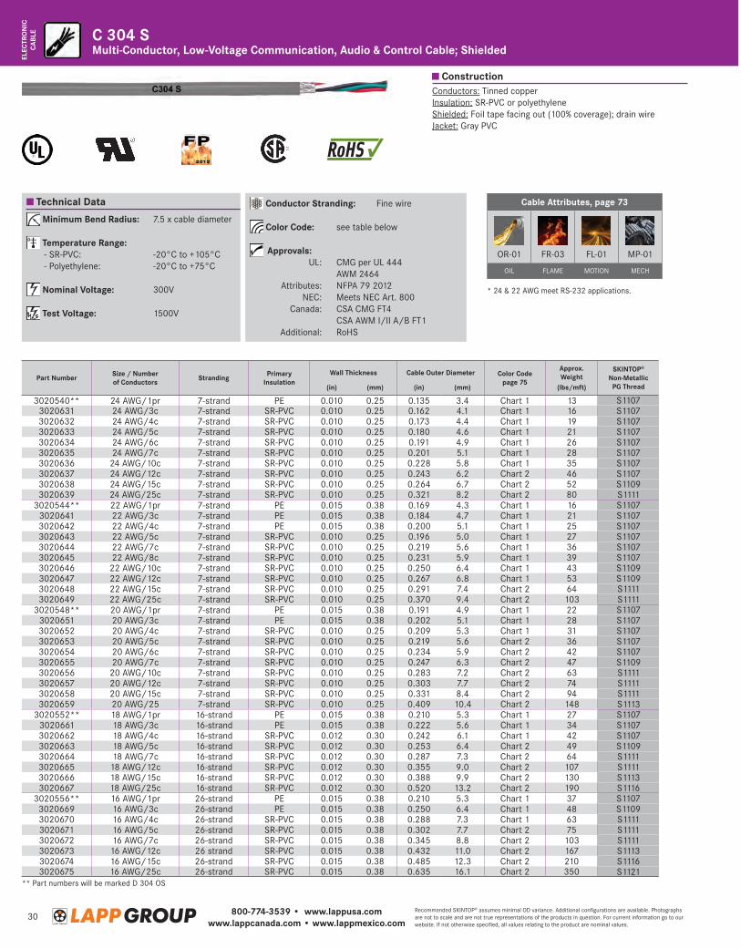
Minimum Bend Radius: 7.5 x cable diameter
Temperature Range: -20°C to +105°C
Nominal Voltage: 300V
Test Voltage: 1500V
Conductor Stranding: Fine wire
Color Code: see table below
Approvals: UL: CMG per UL 444 AWM 2464 Attributes: NFPA 79 2012 NEC: Meets NEC Art. 800 Canada: CSA CMG FT4 CSA AWM I/II A/B FT1 Additional: RoHS
Conductors: Tinned copperInsulation: SR-PVCJacket: Gray PVC
Multi-Conductor, Low-Voltage Communication, Audio & Control Cable; UnshieldedC 304
* 24 & 22 AWG meet RS-232 applications.
Part Number Size / Number of Conductors Stranding Wall Thickness Cable Outer Diameter Color Code
page 75
Approx.Weight
(lbs/mft)
SKINTOP® Non-Metallic
PG Thread(in) (mm) (in) (mm)
3020570 24 AWG/2c 7-strand 0.010 0.25 0.149 3.8 black, red 7 S11073020571 24 AWG/3c 7-strand 0.010 0.25 0.156 4.0 black, red, green 9 S11073020572 24 AWG/4c 7-strand 0.010 0.25 0.168 4.3 Chart 1 14 S11073020573 24 AWG/5c 7-strand 0.010 0.25 0.175 4.4 Chart 1 20 S11073020574 24 AWG/7c 7-strand 0.010 0.25 0.208 5.3 Chart 1 27 S11073020575 24 AWG/10c 7-strand 0.010 0.25 0.226 5.7 Chart 1 33 S11073020576 24 AWG/12c 7-strand 0.010 0.25 0.241 6.1 Chart 1 38 S11073020577 24 AWG/15c 7-strand 0.010 0.25 0.262 6.7 Chart 2 46 S11093020578 24 AWG/25c 7-strand 0.010 0.25 0.319 8.1 Chart 2 75 S11113020582 22 AWG/2c 7-strand 0.010 0.25 0.161 4.1 black, red 10 S11073020583 22 AWG/3c 7-strand 0.010 0.25 0.169 4.3 black, red, green 15 S11073020584 22 AWG/4c 7-strand 0.010 0.25 0.182 4.6 Chart 1 20 S11073020585 22 AWG/5c 7-strand 0.010 0.25 0.194 4.9 Chart 1 25 S11073020586 22 AWG/6c 7-strand 0.010 0.25 0.206 5.2 Chart 1 29 S11073020587 22 AWG/7c 7-strand 0.010 0.25 0.217 5.5 Chart 1 33 S11073020588 22 AWG/8c 7-strand 0.010 0.25 0.229 5.8 Chart 1 37 S11073020589 22 AWG/9c 7-strand 0.010 0.25 0.239 6.1 Chart 1 40 S11073020590 22 AWG/10c 7-strand 0.010 0.25 0.248 6.3 Chart 1 44 S11093020591 22 AWG/12c 7-strand 0.010 0.25 0.265 6.7 Chart 1 50 S11093020592 22 AWG/15c 7-strand 0.010 0.25 0.289 7.3 Chart 2 62 S11113020593 22 AWG/20c 7-strand 0.010 0.25 0.323 8.2 Chart 2 82 S11113020594 22 AWG/25c 7-strand 0.010 0.25 0.354 9.0 Chart 2 100 S11113020598 20 AWG/2c 7-strand 0.010 0.25 0.180 4.6 black, red 13 S11073020599 20 AWG/3c 7-strand 0.010 0.25 0.189 4.8 Chart 1 19 S11073020600 20 AWG/4c 7-strand 0.010 0.25 0.207 5.3 Chart 1 27 S11073020601 20 AWG/5c 7-strand 0.010 0.25 0.217 5.5 Chart 1 33 S11073020602 20 AWG/6c 7-strand 0.010 0.25 0.232 5.9 Chart 1 39 S11073020603 20 AWG/7c 7-strand 0.010 0.25 0.245 6.2 Chart 1 45 S11073020604 20 AWG/9c 7-strand 0.010 0.25 0.270 6.9 Chart 1 57 S11093020605 20 AWG/12c 7-strand 0.010 0.25 0.301 7.6 Chart 1 71 S11113020606 20 AWG/15c 7-strand 0.010 0.25 0.329 8.4 Chart 2 91 S11113020607 18 AWG/2c 16-strand 0.012 0.30 0.209 5.3 black, red 21 S11073020608 18 AWG/3c 16-strand 0.012 0.30 0.221 5.6 Chart 1 27 S11073020609 18 AWG/4c 16-strand 0.012 0.30 0.240 6.1 Chart 1 38 S11073020610 18 AWG/5c 16-strand 0.012 0.30 0.251 6.4 Chart 1 43 S11093020611 18 AWG/7c 16-strand 0.012 0.30 0.285 7.2 Chart 1 60 S11113020612 18 AWG/12c 16-strand 0.012 0.30 0.353 9.0 Chart 2 103 S11113020613 18 AWG/15c 16-strand 0.012 0.30 0.386 9.8 Chart 2 128 S11133020614 18 AWG/25c 16-strand 0.012 0.30 0.492 12.5 Chart 2 206 S11163020615 16 AWG/2c 26-strand 0.015 0.38 0.248 6.3 Chart 2 30 S11093020616 16 AWG/3c 26-strand 0.015 0.38 0.262 6.7 Chart 2 45 S11093020617 16 AWG/4c 26-strand 0.015 0.38 0.286 7.3 Chart 2 59 S11113020618 16 AWG/5c 26-strand 0.015 0.38 0.300 7.6 Chart 2 70 S11113020619 16 AWG/7c 26-strand 0.015 0.38 0.343 8.7 Chart 2 100 S11113020620 16 AWG/12c 26 strand 0.015 0.38 0.430 10.9 Chart 2 173 S11133020621 16 AWG/15c 26-strand 0.015 0.38 0.483 12.3 Chart 2 202 S11163020622 16 AWG/25c 26-strand 0.015 0.38 0.633 16.1 Chart 2 340 S1121
800-774-3539 • www.lappusa.comwww.lappcanada.com • www.lappmexico.com
30Recommended SKINTOP® assumes minimal OD variance. Additional configurations are available. Photographs are not to scale and are not true representations of the products in question. For current information go to our website. If not otherwise specified, all values relating to the product are nominal values.
ELEC
TRO
NIC
CABL
E
Construction
Technical Data Conductor Stranding: Fine wire
Color Code: see table below
Approvals: UL: CMG per UL 444 AWM 2464 Attributes: NFPA 79 2012 NEC: Meets NEC Art. 800 Canada: CSA CMG FT4 CSA AWM I/II A/B FT1 Additional: RoHS
Minimum Bend Radius: 7.5 x cable diameter
Temperature Range: - SR-PVC: -20°C to +105°C - Polyethylene: -20°C to +75°C
Nominal Voltage: 300V
Test Voltage: 1500V
Cable Attributes, page 73
OR-01 FR-03 FL-01 MP-01
OIL FLAME MOTION MECH
Conductors: Tinned copperInsulation: SR-PVC or polyethyleneShielded: Foil tape facing out (100% coverage); drain wireJacket: Gray PVC
Multi-Conductor, Low-Voltage Communication, Audio & Control Cable; ShieldedC 304 S
* 24 & 22 AWG meet RS-232 applications.
** Part numbers will be marked D 304 OS
Part Number Size / Numberof Conductors Stranding Primary
InsulationWall Thickness Cable Outer Diameter Color Code
page 75
Approx.Weight
SKINTOP® Non-Metallic
PG Thread(in) (mm) (in) (mm) (lbs/mft)
3020540** 24 AWG/1pr 7-strand PE 0.010 0.25 0.135 3.4 Chart 1 13 S11073020631 24 AWG/3c 7-strand SR-PVC 0.010 0.25 0.162 4.1 Chart 1 16 S11073020632 24 AWG/4c 7-strand SR-PVC 0.010 0.25 0.173 4.4 Chart 1 19 S11073020633 24 AWG/5c 7-strand SR-PVC 0.010 0.25 0.180 4.6 Chart 1 21 S11073020634 24 AWG/6c 7-strand SR-PVC 0.010 0.25 0.191 4.9 Chart 1 26 S11073020635 24 AWG/7c 7-strand SR-PVC 0.010 0.25 0.201 5.1 Chart 1 28 S11073020636 24 AWG/10c 7-strand SR-PVC 0.010 0.25 0.228 5.8 Chart 1 35 S11073020637 24 AWG/12c 7-strand SR-PVC 0.010 0.25 0.243 6.2 Chart 2 46 S11073020638 24 AWG/15c 7-strand SR-PVC 0.010 0.25 0.264 6.7 Chart 2 52 S11093020639 24 AWG/25c 7-strand SR-PVC 0.010 0.25 0.321 8.2 Chart 2 80 S1111
3020544** 22 AWG/1pr 7-strand PE 0.015 0.38 0.169 4.3 Chart 1 16 S11073020641 22 AWG/3c 7-strand PE 0.015 0.38 0.184 4.7 Chart 1 21 S11073020642 22 AWG/4c 7-strand PE 0.015 0.38 0.200 5.1 Chart 1 25 S11073020643 22 AWG/5c 7-strand SR-PVC 0.010 0.25 0.196 5.0 Chart 1 27 S11073020644 22 AWG/7c 7-strand SR-PVC 0.010 0.25 0.219 5.6 Chart 1 36 S11073020645 22 AWG/8c 7-strand SR-PVC 0.010 0.25 0.231 5.9 Chart 1 39 S11073020646 22 AWG/10c 7-strand SR-PVC 0.010 0.25 0.250 6.4 Chart 1 43 S11093020647 22 AWG/12c 7-strand SR-PVC 0.010 0.25 0.267 6.8 Chart 1 53 S11093020648 22 AWG/15c 7-strand SR-PVC 0.010 0.25 0.291 7.4 Chart 2 64 S11113020649 22 AWG/25c 7-strand SR-PVC 0.010 0.25 0.370 9.4 Chart 2 103 S1111
3020548** 20 AWG/1pr 7-strand PE 0.015 0.38 0.191 4.9 Chart 1 22 S11073020651 20 AWG/3c 7-strand PE 0.015 0.38 0.202 5.1 Chart 1 28 S11073020652 20 AWG/4c 7-strand SR-PVC 0.010 0.25 0.209 5.3 Chart 1 31 S11073020653 20 AWG/5c 7-strand SR-PVC 0.010 0.25 0.219 5.6 Chart 2 36 S11073020654 20 AWG/6c 7-strand SR-PVC 0.010 0.25 0.234 5.9 Chart 2 42 S11073020655 20 AWG/7c 7-strand SR-PVC 0.010 0.25 0.247 6.3 Chart 2 47 S11093020656 20 AWG/10c 7-strand SR-PVC 0.010 0.25 0.283 7.2 Chart 2 63 S11113020657 20 AWG/12c 7-strand SR-PVC 0.010 0.25 0.303 7.7 Chart 2 74 S11113020658 20 AWG/15c 7-strand SR-PVC 0.010 0.25 0.331 8.4 Chart 2 94 S11113020659 20 AWG/25 7-strand SR-PVC 0.010 0.25 0.409 10.4 Chart 2 148 S1113
3020552** 18 AWG/1pr 16-strand PE 0.015 0.38 0.210 5.3 Chart 1 27 S11073020661 18 AWG/3c 16-strand PE 0.015 0.38 0.222 5.6 Chart 1 34 S11073020662 18 AWG/4c 16-strand SR-PVC 0.012 0.30 0.242 6.1 Chart 1 42 S11073020663 18 AWG/5c 16-strand SR-PVC 0.012 0.30 0.253 6.4 Chart 2 49 S11093020664 18 AWG/7c 16-strand SR-PVC 0.012 0.30 0.287 7.3 Chart 2 64 S11113020665 18 AWG/12c 16-strand SR-PVC 0.012 0.30 0.355 9.0 Chart 2 107 S11113020666 18 AWG/15c 16-strand SR-PVC 0.012 0.30 0.388 9.9 Chart 2 130 S11133020667 18 AWG/25c 16-strand SR-PVC 0.012 0.30 0.520 13.2 Chart 2 190 S1116
3020556** 16 AWG/1pr 26-strand PE 0.015 0.38 0.210 5.3 Chart 1 37 S11073020669 16 AWG/3c 26-strand PE 0.015 0.38 0.250 6.4 Chart 1 48 S11093020670 16 AWG/4c 26-strand SR-PVC 0.015 0.38 0.288 7.3 Chart 1 63 S11113020671 16 AWG/5c 26-strand SR-PVC 0.015 0.38 0.302 7.7 Chart 2 75 S11113020672 16 AWG/7c 26-strand SR-PVC 0.015 0.38 0.345 8.8 Chart 2 103 S11113020673 16 AWG/12c 26 strand SR-PVC 0.015 0.38 0.432 11.0 Chart 2 167 S11133020674 16 AWG/15c 26-strand SR-PVC 0.015 0.38 0.485 12.3 Chart 2 210 S11163020675 16 AWG/25c 26-strand SR-PVC 0.015 0.38 0.635 16.1 Chart 2 350 S1121
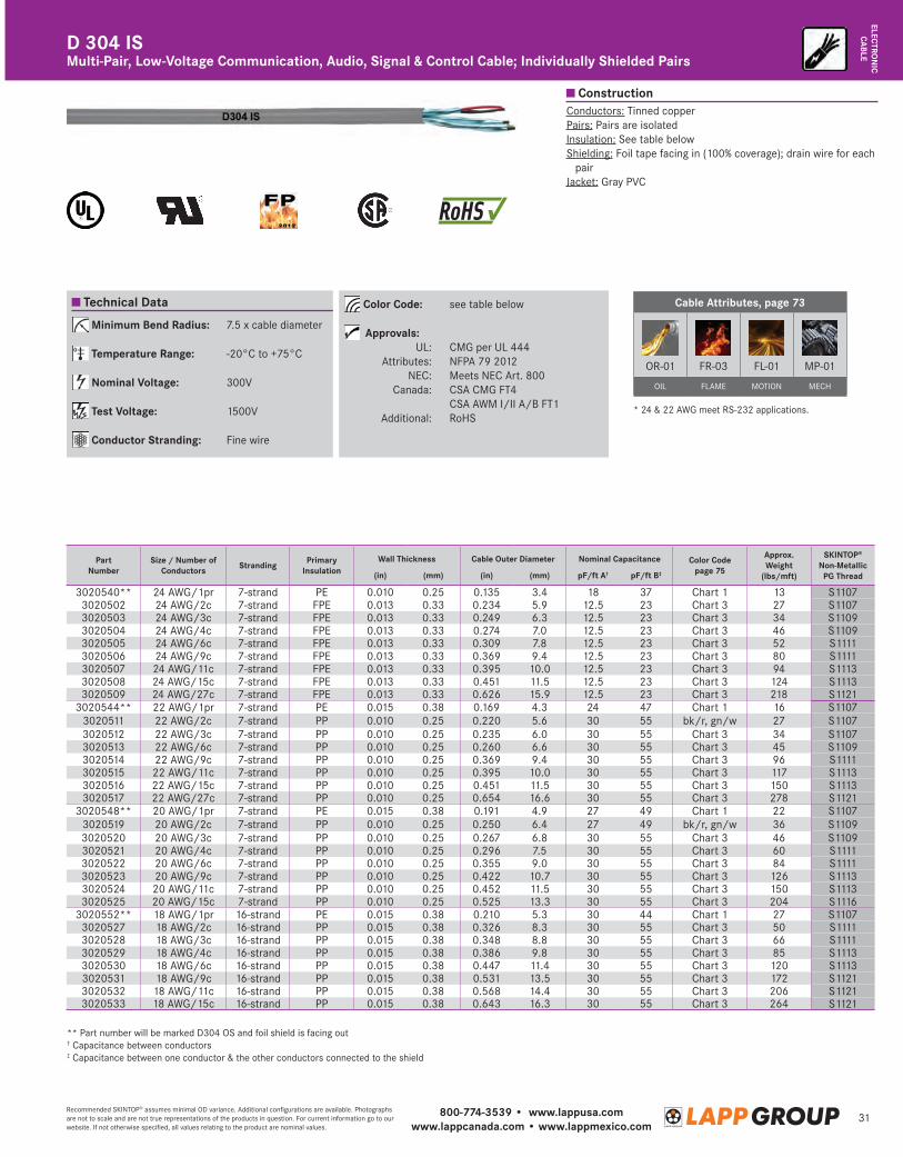
800-774-3539 • www.lappusa.comwww.lappcanada.com • www.lappmexico.com
31Recommended SKINTOP® assumes minimal OD variance. Additional configurations are available. Photographs are not to scale and are not true representations of the products in question. For current information go to our website. If not otherwise specified, all values relating to the product are nominal values.
ELECTRON
ICCA
BLE
Construction
Technical Data
Multi-Pair, Low-Voltage Communication, Audio, Signal & Control Cable; Individually Shielded PairsD 304 IS
Conductors: Tinned copperPairs: Pairs are isolatedInsulation: See table belowShielding: Foil tape facing in (100% coverage); drain wire for each
pairJacket: Gray PVC
Cable Attributes, page 73
OR-01 FR-03 FL-01 MP-01
OIL FLAME MOTION MECH
Minimum Bend Radius: 7.5 x cable diameter
Temperature Range: -20°C to +75°C
Nominal Voltage: 300V
Test Voltage: 1500V
Conductor Stranding: Fine wire
Color Code: see table below
Approvals: UL: CMG per UL 444 Attributes: NFPA 79 2012 NEC: Meets NEC Art. 800 Canada: CSA CMG FT4 CSA AWM I/II A/B FT1 Additional: RoHS
* 24 & 22 AWG meet RS-232 applications.
** Part number will be marked D304 OS and foil shield is facing out† Capacitance between conductors‡ Capacitance between one conductor & the other conductors connected to the shield
Part Number
Size / Number of Conductors Stranding Primary
InsulationWall Thickness Cable Outer Diameter Nominal Capacitance Color Code
page 75
Approx.Weight
(lbs/mft)
SKINTOP® Non-Metallic
PG Thread(in) (mm) (in) (mm) pF/ft A† pF/ft B‡
3020540** 24 AWG/1pr 7-strand PE 0.010 0.25 0.135 3.4 18 37 Chart 1 13 S11073020502 24 AWG/2c 7-strand FPE 0.013 0.33 0.234 5.9 12.5 23 Chart 3 27 S11073020503 24 AWG/3c 7-strand FPE 0.013 0.33 0.249 6.3 12.5 23 Chart 3 34 S11093020504 24 AWG/4c 7-strand FPE 0.013 0.33 0.274 7.0 12.5 23 Chart 3 46 S11093020505 24 AWG/6c 7-strand FPE 0.013 0.33 0.309 7.8 12.5 23 Chart 3 52 S11113020506 24 AWG/9c 7-strand FPE 0.013 0.33 0.369 9.4 12.5 23 Chart 3 80 S11113020507 24 AWG/11c 7-strand FPE 0.013 0.33 0.395 10.0 12.5 23 Chart 3 94 S11133020508 24 AWG/15c 7-strand FPE 0.013 0.33 0.451 11.5 12.5 23 Chart 3 124 S11133020509 24 AWG/27c 7-strand FPE 0.013 0.33 0.626 15.9 12.5 23 Chart 3 218 S1121
3020544** 22 AWG/1pr 7-strand PE 0.015 0.38 0.169 4.3 24 47 Chart 1 16 S11073020511 22 AWG/2c 7-strand PP 0.010 0.25 0.220 5.6 30 55 bk/r, gn/w 27 S11073020512 22 AWG/3c 7-strand PP 0.010 0.25 0.235 6.0 30 55 Chart 3 34 S11073020513 22 AWG/6c 7-strand PP 0.010 0.25 0.260 6.6 30 55 Chart 3 45 S11093020514 22 AWG/9c 7-strand PP 0.010 0.25 0.369 9.4 30 55 Chart 3 96 S11113020515 22 AWG/11c 7-strand PP 0.010 0.25 0.395 10.0 30 55 Chart 3 117 S11133020516 22 AWG/15c 7-strand PP 0.010 0.25 0.451 11.5 30 55 Chart 3 150 S11133020517 22 AWG/27c 7-strand PP 0.010 0.25 0.654 16.6 30 55 Chart 3 278 S1121
3020548** 20 AWG/1pr 7-strand PE 0.015 0.38 0.191 4.9 27 49 Chart 1 22 S11073020519 20 AWG/2c 7-strand PP 0.010 0.25 0.250 6.4 27 49 bk/r, gn/w 36 S11093020520 20 AWG/3c 7-strand PP 0.010 0.25 0.267 6.8 30 55 Chart 3 46 S11093020521 20 AWG/4c 7-strand PP 0.010 0.25 0.296 7.5 30 55 Chart 3 60 S11113020522 20 AWG/6c 7-strand PP 0.010 0.25 0.355 9.0 30 55 Chart 3 84 S11113020523 20 AWG/9c 7-strand PP 0.010 0.25 0.422 10.7 30 55 Chart 3 126 S11133020524 20 AWG/11c 7-strand PP 0.010 0.25 0.452 11.5 30 55 Chart 3 150 S11133020525 20 AWG/15c 7-strand PP 0.010 0.25 0.525 13.3 30 55 Chart 3 204 S1116
3020552** 18 AWG/1pr 16-strand PE 0.015 0.38 0.210 5.3 30 44 Chart 1 27 S11073020527 18 AWG/2c 16-strand PP 0.015 0.38 0.326 8.3 30 55 Chart 3 50 S11113020528 18 AWG/3c 16-strand PP 0.015 0.38 0.348 8.8 30 55 Chart 3 66 S11113020529 18 AWG/4c 16-strand PP 0.015 0.38 0.386 9.8 30 55 Chart 3 85 S11133020530 18 AWG/6c 16-strand PP 0.015 0.38 0.447 11.4 30 55 Chart 3 120 S11133020531 18 AWG/9c 16-strand PP 0.015 0.38 0.531 13.5 30 55 Chart 3 172 S11213020532 18 AWG/11c 16-strand PP 0.015 0.38 0.568 14.4 30 55 Chart 3 206 S11213020533 18 AWG/15c 16-strand PP 0.015 0.38 0.643 16.3 30 55 Chart 3 264 S1121
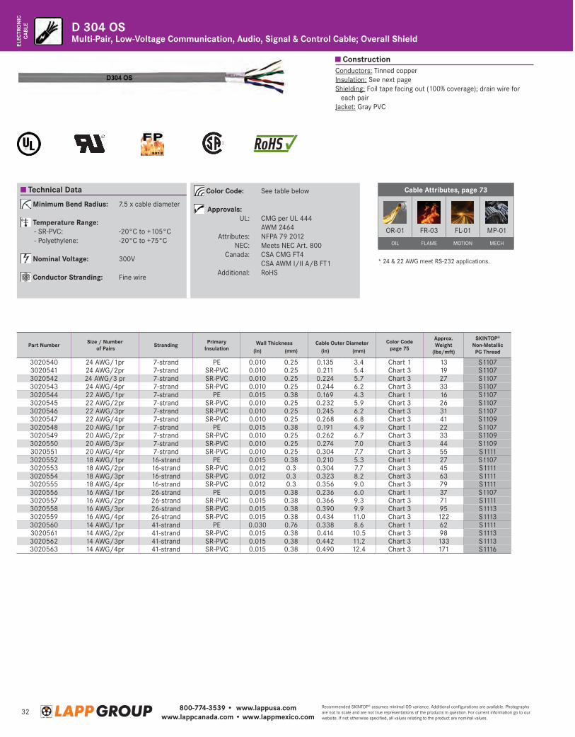
800-774-3539 • www.lappusa.comwww.lappcanada.com • www.lappmexico.com
32Recommended SKINTOP® assumes minimal OD variance. Additional configurations are available. Photographs are not to scale and are not true representations of the products in question. For current information go to our website. If not otherwise specified, all values relating to the product are nominal values.
ELEC
TRO
NIC
CABL
E
Construction
Technical Data Cable Attributes, page 73
OR-01 FR-03 FL-01 MP-01
OIL FLAME MOTION MECH
Conductors: Tinned copperInsulation: See next pageShielding: Foil tape facing out (100% coverage); drain wire for
each pairJacket: Gray PVC
Minimum Bend Radius: 7.5 x cable diameter
Temperature Range: - SR-PVC: -20°C to +105°C - Polyethylene: -20°C to +75°C
Nominal Voltage: 300V
Conductor Stranding: Fine wire
Color Code: See table below
Approvals: UL: CMG per UL 444 AWM 2464 Attributes: NFPA 79 2012 NEC: Meets NEC Art. 800 Canada: CSA CMG FT4 CSA AWM I/II A/B FT1 Additional: RoHS
D 304 OSMulti-Pair, Low-Voltage Communication, Audio, Signal & Control Cable; Overall Shield
* 24 & 22 AWG meet RS-232 applications.
Part Number Size / Number of Pairs Stranding Primary
InsulationWall Thickness Cable Outer Diameter Color Code
page 75
Approx.Weight
(lbs/mft)
SKINTOP® Non-Metallic
PG Thread(in) (mm) (in) (mm)
3020540 24 AWG/1pr 7-strand PE 0.010 0.25 0.135 3.4 Chart 1 13 S11073020541 24 AWG/2pr 7-strand SR-PVC 0.010 0.25 0.211 5.4 Chart 3 19 S11073020542 24 AWG/3 pr 7-strand SR-PVC 0.010 0.25 0.224 5.7 Chart 3 27 S11073020543 24 AWG/4pr 7-strand SR-PVC 0.010 0.25 0.244 6.2 Chart 3 33 S11073020544 22 AWG/1pr 7-strand PE 0.015 0.38 0.169 4.3 Chart 1 16 S11073020545 22 AWG/2pr 7-strand SR-PVC 0.010 0.25 0.232 5.9 Chart 3 26 S11073020546 22 AWG/3pr 7-strand SR-PVC 0.010 0.25 0.245 6.2 Chart 3 31 S11073020547 22 AWG/4pr 7-strand SR-PVC 0.010 0.25 0.268 6.8 Chart 3 41 S11093020548 20 AWG/1pr 7-strand PE 0.015 0.38 0.191 4.9 Chart 1 22 S11073020549 20 AWG/2pr 7-strand SR-PVC 0.010 0.25 0.262 6.7 Chart 3 33 S11093020550 20 AWG/3pr 7-strand SR-PVC 0.010 0.25 0.274 7.0 Chart 3 44 S11093020551 20 AWG/4pr 7-strand SR-PVC 0.010 0.25 0.304 7.7 Chart 3 55 S11113020552 18 AWG/1pr 16-strand PE 0.015 0.38 0.210 5.3 Chart 1 27 S11073020553 18 AWG/2pr 16-strand SR-PVC 0.012 0.3 0.304 7.7 Chart 3 45 S11113020554 18 AWG/3pr 16-strand SR-PVC 0.012 0.3 0.323 8.2 Chart 3 63 S11113020555 18 AWG/4pr 16-strand SR-PVC 0.012 0.3 0.356 9.0 Chart 3 79 S11113020556 16 AWG/1pr 26-strand PE 0.015 0.38 0.236 6.0 Chart 1 37 S11073020557 16 AWG/2pr 26-strand SR-PVC 0.015 0.38 0.366 9.3 Chart 3 71 S11113020558 16 AWG/3pr 26-strand SR-PVC 0.015 0.38 0.390 9.9 Chart 3 95 S11133020559 16 AWG/4pr 26-strand SR-PVC 0.015 0.38 0.434 11.0 Chart 3 122 S11133020560 14 AWG/1pr 41-strand PE 0.030 0.76 0.338 8.6 Chart 1 62 S11113020561 14 AWG/2pr 41-strand SR-PVC 0.015 0.38 0.414 10.5 Chart 3 98 S11133020562 14 AWG/3pr 41-strand SR-PVC 0.015 0.38 0.442 11.2 Chart 3 133 S11133020563 14 AWG/4pr 41-strand SR-PVC 0.015 0.38 0.490 12.4 Chart 3 171 S1116
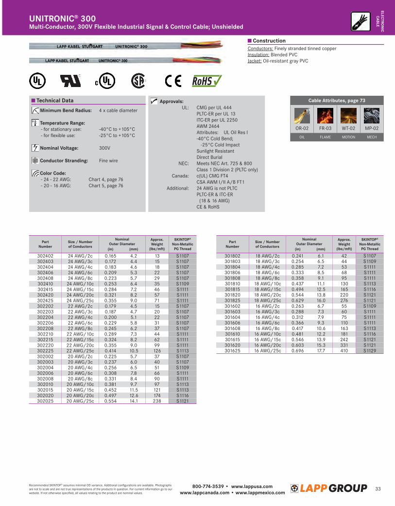
800-774-3539 • www.lappusa.comwww.lappcanada.com • www.lappmexico.com
33Recommended SKINTOP® assumes minimal OD variance. Additional configurations are available. Photographs are not to scale and are not true representations of the products in question. For current information go to our website. If not otherwise specified, all values relating to the product are nominal values.
ELECTRON
ICCA
BLE
Technical Data Cable Attributes, page 73
OR-02 FR-03 WT-02 MP-02
OIL FLAME MOTION MECH
Minimum Bend Radius: 4 x cable diameter
Temperature Range: - for stationary use: -40°C to +105°C - for flexible use: -25°C to +105°C
Nominal Voltage: 300V
Conductor Stranding: Fine wire
Color Code: - 24 - 22 AWG: Chart 4, page 76 - 20 - 16 AWG: Chart 5, page 76
Approvals: UL: CMG per UL 444 PLTC-ER per UL 13 ITC-ER per UL 2250 AWM 2464 Attributes: UL Oil Res I -4 0°C Cold Bend;
-25°C Cold Impact Sunlight Resistant Direct Burial NEC: Meets NEC Art. 725 & 800 Class 1 Division 2 (PLTC only) Canada: c(UL) CMG FT4 CSA AWM I/II A/B FT1 Additional: 24 AWG is not PLTC P LTC-ER & ITC-ER
(18 & 16 AWG) CE & RoHS
Conductors: Finely stranded tinned copperInsulation: Blended PVCJacket: Oil-resistant gray PVC
Multi-Conductor, 300V Flexible Industrial Signal & Control Cable; UnshieldedUNITRONIC ® 300
PartNumber
Size / Number of Conductors
Nominal Outer Diameter
Approx.Weight
(lbs/mft)
SKINTOP®
Non-MetallicPG Thread(in) (mm)
302402 24 AWG/2c 0.165 4.2 13 S1107302403 24 AWG/3c 0.172 4.4 15 S1107302404 24 AWG/4c 0.183 4.6 18 S1107302406 24 AWG/6c 0.209 5.3 22 S1107302408 24 AWG/8c 0.223 5.7 29 S1107302410 24 AWG/10c 0.253 6.4 35 S1109302415 24 AWG/15c 0.284 7.2 46 S1111302420 24 AWG/20c 0.321 8.2 57 S1111302425 24 AWG/25c 0.355 9.0 71 S1111302202 22 AWG/2c 0.179 4.5 15 S1107302203 22 AWG/3c 0.187 4.7 20 S1107302204 22 AWG/4c 0.200 5.1 22 S1107302206 22 AWG/6c 0.229 5.8 31 S1107302208 22 AWG/8c 0.245 6.2 37 S1107302210 22 AWG/10c 0.289 7.3 44 S1111302215 22 AWG/15c 0.324 8.2 62 S1111302220 22 AWG/20c 0.355 9.0 99 S1111302225 22 AWG/25c 0.414 10.5 126 S1113302002 20 AWG/2c 0.225 5.7 37 S1107302003 20 AWG/3c 0.237 6.0 40 S1107302004 20 AWG/4c 0.256 6.5 51 S1109302006 20 AWG/6c 0.308 7.8 66 S1111302008 20 AWG/8c 0.331 8.4 90 S1111302010 20 AWG/10c 0.381 9.7 97 S1113302015 20 AWG/15c 0.452 11.5 121 S1113302020 20 AWG/20c 0.497 12.6 174 S1116302025 20 AWG/25c 0.554 14.1 238 S1121
Construction
PartNumber
Size / Number of Conductors
Nominal Outer Diameter
Approx.Weight
(lbs/mft)
SKINTOP®
Non-MetallicPG Thread(in) (mm)
301802 18 AWG/2c 0.241 6.1 42 S1107301803 18 AWG/3c 0.254 6.5 44 S1109301804 18 AWG/4c 0.285 7.2 53 S1111301806 18 AWG/6c 0.333 8.5 68 S1111301808 18 AWG/8c 0.358 9.1 95 S1111301810 18 AWG/10c 0.437 11.1 130 S1113301815 18 AWG/15c 0.494 12.5 165 S1116301820 18 AWG/20c 0.544 13.8 220 S1121301825 18 AWG/25c 0.629 16.0 276 S1121301602 16 AWG/2c 0.263 6.7 55 S1109301603 16 AWG/3c 0.288 7.3 60 S1111301604 16 AWG/4c 0.312 7.9 75 S1111301606 16 AWG/6c 0.366 9.3 110 S1111301608 16 AWG/8c 0.417 10.6 163 S1113301610 16 AWG/10c 0.481 12.2 181 S1116301615 16 AWG/15c 0.546 13.9 242 S1121301620 16 AWG/20c 0.603 15.3 331 S1121301625 16 AWG/25c 0.696 17.7 410 S1129
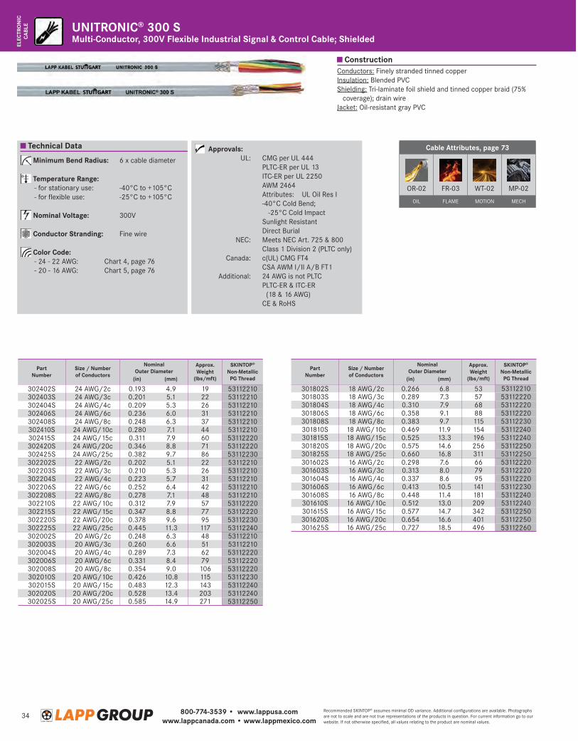
800-774-3539 • www.lappusa.comwww.lappcanada.com • www.lappmexico.com
34Recommended SKINTOP® assumes minimal OD variance. Additional configurations are available. Photographs are not to scale and are not true representations of the products in question. For current information go to our website. If not otherwise specified, all values relating to the product are nominal values.
ELEC
TRO
NIC
CABL
E
Cable Attributes, page 73
OR-02 FR-03 WT-02 MP-02
OIL FLAME MOTION MECH
Conductors: Finely stranded tinned copperInsulation: Blended PVCShielding: Tri-laminate foil shield and tinned copper braid (75%
coverage); drain wireJacket: Oil-resistant gray PVC
Multi-Conductor, 300V Flexible Industrial Signal & Control Cable; ShieldedUNITRONIC® 300 S
PartNumber
Size / Number of Conductors
Nominal Outer Diameter
Approx.Weight
(lbs/mft)
SKINTOP®
Non-MetallicPG Thread(in) (mm)
302402S 24 AWG/2c 0.193 4.9 19 53112210302403S 24 AWG/3c 0.201 5.1 22 53112210302404S 24 AWG/4c 0.209 5.3 26 53112210302406S 24 AWG/6c 0.236 6.0 31 53112210302408S 24 AWG/8c 0.248 6.3 37 53112210302410S 24 AWG/10c 0.280 7.1 44 53112210302415S 24 AWG/15c 0.311 7.9 60 53112220302420S 24 AWG/20c 0.346 8.8 71 53112220302425S 24 AWG/25c 0.382 9.7 86 53112230302202S 22 AWG/2c 0.202 5.1 22 53112210302203S 22 AWG/3c 0.210 5.3 26 53112210302204S 22 AWG/4c 0.223 5.7 31 53112210302206S 22 AWG/6c 0.252 6.4 42 53112210302208S 22 AWG/8c 0.278 7.1 48 53112210302210S 22 AWG/10c 0.312 7.9 57 53112220302215S 22 AWG/15c 0.347 8.8 77 53112220302220S 22 AWG/20c 0.378 9.6 95 53112230302225S 22 AWG/25c 0.445 11.3 117 53112240302002S 20 AWG/2c 0.248 6.3 48 53112210302003S 20 AWG/3c 0.260 6.6 51 53112210302004S 20 AWG/4c 0.289 7.3 62 53112220302006S 20 AWG/6c 0.331 8.4 79 53112220302008S 20 AWG/8c 0.354 9.0 106 53112220302010S 20 AWG/10c 0.426 10.8 115 53112230302015S 20 AWG/15c 0.483 12.3 143 53112240302020S 20 AWG/20c 0.528 13.4 203 53112240302025S 20 AWG/25c 0.585 14.9 271 53112250
Construction
Technical Data
Minimum Bend Radius: 6 x cable diameter
Temperature Range: - for stationary use: -40°C to +105°C - for flexible use: -25°C to +105°C
Nominal Voltage: 300V
Conductor Stranding: Fine wire
Color Code: - 24 - 22 AWG: Chart 4, page 76 - 20 - 16 AWG: Chart 5, page 76
Approvals: UL: CMG per UL 444 PLTC-ER per UL 13 ITC-ER per UL 2250 AWM 2464 Attributes: UL Oil Res I -4 0°C Cold Bend;
-25°C Cold Impact Sunlight Resistant Direct Burial NEC: Meets NEC Art. 725 & 800 Class 1 Division 2 (PLTC only) Canada: c(UL) CMG FT4 CSA AWM I/II A/B FT1 Additional: 24 AWG is not PLTC P LTC-ER & ITC-ER
(18 & 16 AWG) CE & RoHS
PartNumber
Size / Number of Conductors
Nominal Outer Diameter
Approx.Weight
(lbs/mft)
SKINTOP®
Non-MetallicPG Thread(in) (mm)
301802S 18 AWG/2c 0.266 6.8 53 53112210301803S 18 AWG/3c 0.289 7.3 57 53112220301804S 18 AWG/4c 0.310 7.9 68 53112220301806S 18 AWG/6c 0.358 9.1 88 53112220301808S 18 AWG/8c 0.383 9.7 115 53112230301810S 18 AWG/10c 0.469 11.9 154 53112240301815S 18 AWG/15c 0.525 13.3 196 53112240301820S 18 AWG/20c 0.575 14.6 256 53112250301825S 18 AWG/25c 0.660 16.8 311 53112250301602S 16 AWG/2c 0.298 7.6 66 53112220301603S 16 AWG/3c 0.313 8.0 79 53112220301604S 16 AWG/4c 0.337 8.6 95 53112220301606S 16 AWG/6c 0.413 10.5 141 53112230301608S 16 AWG/8c 0.448 11.4 181 53112240301610S 16 AWG/10c 0.512 13.0 209 53112240301615S 16 AWG/15c 0.577 14.7 342 53112250301620S 16 AWG/20c 0.654 16.6 401 53112250301625S 16 AWG/25c 0.727 18.5 496 53112260
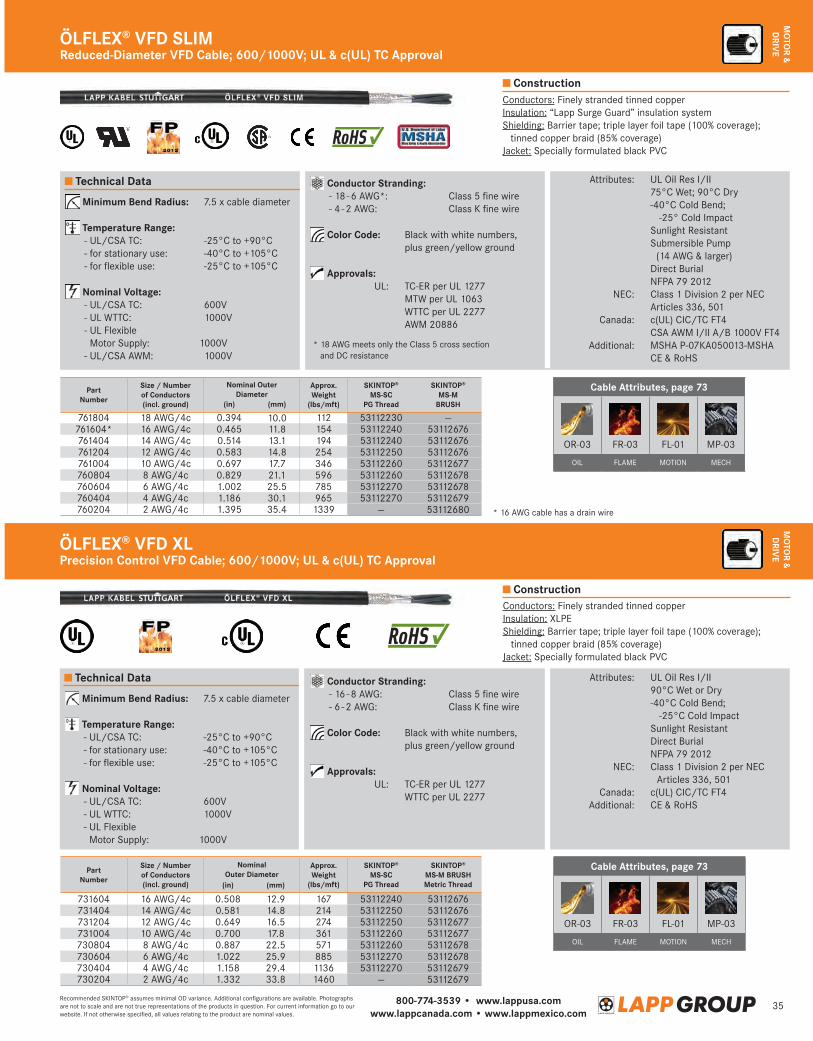
800-774-3539 • www.lappusa.comwww.lappcanada.com • www.lappmexico.com
35Recommended SKINTOP® assumes minimal OD variance. Additional configurations are available. Photographs are not to scale and are not true representations of the products in question. For current information go to our website. If not otherwise specified, all values relating to the product are nominal values.
MO
TOR &
DRIV
E
Construction
Construction
Reduced-Diameter VFD Cable; 600/1000V; UL & c(UL) TC ApprovalÖLFLEX® VFD SLIM
Technical Data
Minimum Bend Radius: 7.5 x cable diameter
Temperature Range: - UL/CSA TC: -25°C to +90°C - for stationary use: -40°C to +105°C - for flexible use: -25°C to +105°C
Nominal Voltage: - UL/CSA TC: 600V - UL WTTC: 1000V - UL Flexible
Motor Supply: 1000V - UL/CSA AWM: 1000V
Conductor Stranding: - 18 - 6 AWG*: Class 5 fine wire - 4 - 2 AWG: Class K fine wire
Color Code: Black with white numbers, plus green/yellow ground
Approvals: UL: TC-ER per UL 1277 MTW per UL 1063 WTTC per UL 2277 AWM 20886
Attributes: UL Oil Res I/II 75°C Wet; 90°C Dry -4 0°C Cold Bend;
-25° Cold Impact Sunlight Resistant S ubmersible Pump
(14 AWG & larger) Direct Burial NFPA 79 2012 NEC: Class 1 Division 2 per NEC
Articles 336, 501 Canada: c(UL) CIC/TC FT4 CSA AWM I/II A/B 1000V FT4 Additional: MSHA P-07KA050013-MSHA CE & RoHS
Cable Attributes, page 73
OR-03 FR-03 FL-01 MP-03
OIL FLAME MOTION MECH
Conductors: Finely stranded tinned copperInsulation: “Lapp Surge Guard” insulation systemS hielding: Barrier tape; triple layer foil tape (100% coverage);
tinned copper braid (85% coverage)Jacket: Specially formulated black PVC
PartNumber
Size / Number of Conductors(incl. ground)
Nominal Outer Diameter
Approx. Weight
(lbs/mft)
SKINTOP® MS-SC
PG Thread
SKINTOP®
MS-M BRUSH(in) (mm)
761804 18 AWG/4c 0.394 10.0 112 53112230 —761604* 16 AWG/4c 0.465 11.8 154 53112240 53112676761404 14 AWG/4c 0.514 13.1 194 53112240 53112676761204 12 AWG/4c 0.583 14.8 254 53112250 53112676761004 10 AWG/4c 0.697 17.7 346 53112260 53112677760804 8 AWG/4c 0.829 21.1 596 53112260 53112678760604 6 AWG/4c 1.002 25.5 785 53112270 53112678760404 4 AWG/4c 1.186 30.1 965 53112270 53112679760204 2 AWG/4c 1.395 35.4 1339 — 53112680 * 16 AWG cable has a drain wire
Precision Control VFD Cable; 600/1000V; UL & c(UL) TC ApprovalÖLFLEX® VFD XL
Cable Attributes, page 73
OR-03 FR-03 FL-01 MP-03
OIL FLAME MOTION MECH
Technical Data
Minimum Bend Radius: 7.5 x cable diameter
Temperature Range: - UL/CSA TC: -25°C to +90°C - for stationary use: -40°C to +105°C - for flexible use: -25°C to +105°C
Nominal Voltage: - UL/CSA TC: 600V - UL WTTC: 1000V - UL Flexible
Motor Supply: 1000V
Conductor Stranding: - 16 - 8 AWG: Class 5 fine wire - 6 - 2 AWG: Class K fine wire
Color Code: Black with white numbers, plus green/yellow ground
Approvals: UL: TC-ER per UL 1277 WTTC per UL 2277
Attributes: UL Oil Res I/II 90°C Wet or Dry -4 0°C Cold Bend;
-25°C Cold Impact Sunlight Resistant Direct Burial NFPA 79 2012 NEC: C lass 1 Division 2 per NEC
Articles 336, 501 Canada: c(UL) CIC/TC FT4 Additional: CE & RoHS
Conductors: Finely stranded tinned copperInsulation: XLPES hielding: Barrier tape; triple layer foil tape (100% coverage);
tinned copper braid (85% coverage)Jacket: Specially formulated black PVC
PartNumber
Size / Number of Conductors(incl. ground)
Nominal Outer Diameter
Approx. Weight
(lbs/mft)
SKINTOP® MS-SC
PG Thread
SKINTOP®
MS-M BRUSHMetric Thread(in) (mm)
731604 16 AWG/4c 0.508 12.9 167 53112240 53112676731404 14 AWG/4c 0.581 14.8 214 53112250 53112676731204 12 AWG/4c 0.649 16.5 274 53112250 53112677731004 10 AWG/4c 0.700 17.8 361 53112260 53112677730804 8 AWG/4c 0.887 22.5 571 53112260 53112678730604 6 AWG/4c 1.022 25.9 885 53112270 53112678730404 4 AWG/4c 1.158 29.4 1136 53112270 53112679730204 2 AWG/4c 1.332 33.8 1460 — 53112679
* 18 AWG meets only the Class 5 cross section and DC resistance
MO
TOR &
DRIV
E
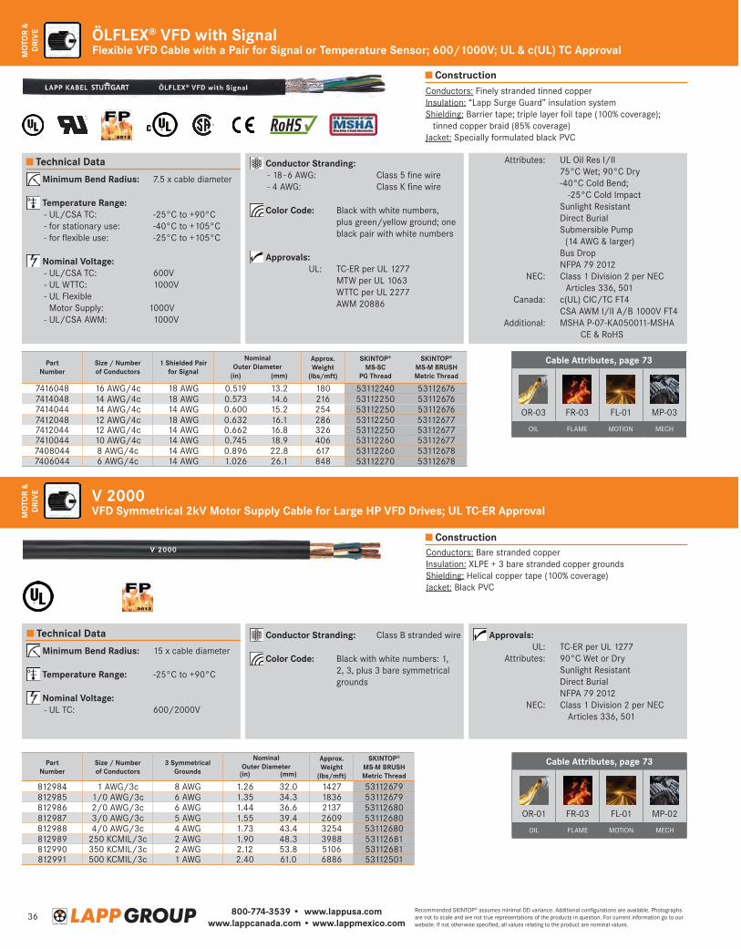
800-774-3539 • www.lappusa.comwww.lappcanada.com • www.lappmexico.com
36Recommended SKINTOP® assumes minimal OD variance. Additional configurations are available. Photographs are not to scale and are not true representations of the products in question. For current information go to our website. If not otherwise specified, all values relating to the product are nominal values.
MO
TOR
& D
RIV
E
Construction
Construction
Flexible VFD Cable with a Pair for Signal or Temperature Sensor; 600/1000V; UL & c(UL) TC ApprovalÖLFLEX® VFD with Signal
Cable Attributes, page 73
OR-03 FR-03 FL-01 MP-03
OIL FLAME MOTION MECH
Conductors: Finely stranded tinned copperInsulation: “Lapp Surge Guard” insulation systemS hielding: Barrier tape; triple layer foil tape (100% coverage);
tinned copper braid (85% coverage)Jacket: Specially formulated black PVC
Technical Data Conductor Stranding: - 18 - 6 AWG: Class 5 fine wire - 4 AWG: Class K fine wire
Color Code: Black with white numbers, plus green/yellow ground; one black pair with white numbers
Approvals:
UL: TC-ER per UL 1277 MTW per UL 1063 WTTC per UL 2277 AWM 20886
Attributes: UL Oil Res I/II 75°C Wet; 90°C Dry -4 0°C Cold Bend;
-25°C Cold Impact Sunlight Resistant Direct Burial S ubmersible Pump
(14 AWG & larger) Bus Drop NFPA 79 2012 NEC: C lass 1 Division 2 per NEC
Articles 336, 501 Canada: c(UL) CIC/TC FT4 CSA AWM I/II A/B 1000V FT4 Additional: MSHA P-07-KA050011-MSHA CE & RoHS
Minimum Bend Radius: 7.5 x cable diameter
Temperature Range: - UL/CSA TC: -25°C to +90°C - for stationary use: -40°C to +105°C - for flexible use: -25°C to +105°C
Nominal Voltage: - UL/CSA TC: 600V - UL WTTC: 1000V - UL Flexible
Motor Supply: 1000V - UL/CSA AWM: 1000V
PartNumber
Size / Number of Conductors
1 Shielded Pair for Signal
Nominal Outer Diameter
Approx. Weight
(lbs/mft)
SKINTOP® MS-SC
PG Thread
SKINTOP®
MS-M BRUSHMetric Thread(in) (mm)
7416048 16 AWG/4c 18 AWG 0.519 13.2 180 53112240 531126767414048 14 AWG/4c 18 AWG 0.573 14.6 216 53112250 531126767414044 14 AWG/4c 14 AWG 0.600 15.2 254 53112250 531126767412048 12 AWG/4c 18 AWG 0.632 16.1 286 53112250 531126777412044 12 AWG/4c 14 AWG 0.662 16.8 326 53112250 531126777410044 10 AWG/4c 14 AWG 0.745 18.9 406 53112260 531126777408044 8 AWG/4c 14 AWG 0.896 22.8 617 53112260 531126787406044 6 AWG/4c 14 AWG 1.026 26.1 848 53112270 53112678
VFD Symmetrical 2kV Motor Supply Cable for Large HP VFD Drives; UL TC-ER ApprovalV 2000
Conductors: Bare stranded copperInsulation: XLPE + 3 bare stranded copper groundsShielding: Helical copper tape (100% coverage)Jacket: Black PVC
PartNumber
Size / Numberof Conductors
3 Symmetrical Grounds
Nominal Outer Diameter
Approx. Weight
(lbs/mft)
SKINTOP®
MS-M BRUSHMetric Thread(in) (mm)
812984 1 AWG/3c 8 AWG 1.26 32.0 1427 53112679812985 1/0 AWG/3c 6 AWG 1.35 34.3 1836 53112679812986 2/0 AWG/3c 6 AWG 1.44 36.6 2137 53112680812987 3/0 AWG/3c 5 AWG 1.55 39.4 2609 53112680812988 4/0 AWG/3c 4 AWG 1.73 43.4 3254 53112680812989 250 KCMIL/3c 2 AWG 1.90 48.3 3988 53112681812990 350 KCMIL/3c 2 AWG 2.12 53.8 5106 53112681812991 500 KCMIL/3c 1 AWG 2.40 61.0 6886 53112501
Technical Data Conductor Stranding: Class B stranded wire
Color Code: Black with white numbers: 1, 2, 3, plus 3 bare symmetrical grounds
Approvals: UL: TC-ER per UL 1277 Attributes: 90°C Wet or Dry Sunlight Resistant Direct Burial NFPA 79 2012 NEC: Cl ass 1 Division 2 per NEC
Articles 336, 501
Minimum Bend Radius: 15 x cable diameter
Temperature Range: -25°C to +90°C
Nominal Voltage: - UL TC: 600/2000V
Cable Attributes, page 73
OR-01 FR-03 FL-01 MP-02
OIL FLAME MOTION MECH
MO
TOR
& D
RIV
E
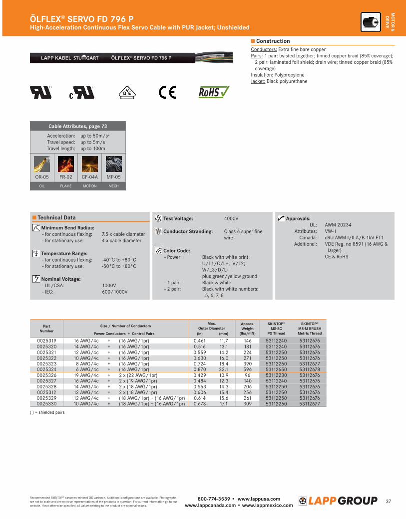
800-774-3539 • www.lappusa.comwww.lappcanada.com • www.lappmexico.com
37Recommended SKINTOP® assumes minimal OD variance. Additional configurations are available. Photographs are not to scale and are not true representations of the products in question. For current information go to our website. If not otherwise specified, all values relating to the product are nominal values.
MO
TOR &
DRIV
EHigh-Acceleration Continuous Flex Servo Cable with PUR Jacket; UnshieldedÖLFLEX® SERVO FD 796 P
Conductors: Extra fine bare copperPairs: 1 pair: twisted together; tinned copper braid (85% coverage);
2 pair: laminated foil shield; drain wire; tinned copper braid (85% coverage)
Insulation: PolypropyleneJacket: Black polyurethane
Construction
Cable Attributes, page 73
Acceleration:Travel speed:Travel length:
up to 50m/s2
up to 5m/sup to 100m
OR-05 FR-02 CF-04A MP-05
OIL FLAME MOTION MECH
Test Voltage: 4000V
Conductor Stranding: Class 6 super fine wire
Color Code: - Power: Black with white print:
U/L1/C/L+; V/L2; W/L3/D/L - plus green/yellow ground
- 1 pair: Black & white - 2 pair: B lack with white numbers:
5, 6, 7, 8
Minimum Bend Radius: - for continuous flexing: 7.5 x cable diameter - for stationary use: 4 x cable diameter
Temperature Range: - for continuous flexing: -40°C to +80°C - for stationary use: -50°C to +80°C
Nominal Voltage: - UL/CSA: 1000V - IEC: 600/1000V
Approvals: UL: AWM 20234 Attributes: VW-1 Canada: cRU AWM I/II A/B 1kV FT1 Additional: V DE Reg. no 8591 (16 AWG &
larger) CE & RoHS
PartNumber
Size / Number of Conductors Max. Outer Diameter
Approx. Weight
(lbs/mft)
SKINTOP® MS-SC
PG Thread
SKINTOP®
MS-M BRUSHMetric ThreadPower Conductors + Control Pairs (in) (mm)
0025319 16 AWG/4c + (16 AWG/1pr) 0.461 11.7 146 53112240 531126760025320 14 AWG/4c + (16 AWG/1pr) 0.516 13.1 181 53112240 531126760025321 12 AWG/4c + (16 AWG/1pr) 0.559 14.2 224 53112250 531126760025322 10 AWG/4c + (16 AWG/1pr) 0.630 16.0 271 53112250 531126760025323 8 AWG/4c + (16 AWG/1pr) 0.724 18.4 390 53112260 531126770025324 6 AWG/4c + (16 AWG/1pr) 0.870 22.1 596 53112650 531126780025326 19 AWG/4c + 2 x (22 AWG/1pr) 0.429 10.9 96 53112230 531126760025327 16 AWG/4c + 2 x (19 AWG/1pr) 0.484 12.3 140 53112240 531126760025328 14 AWG/4c + 2 x (18 AWG/1pr) 0.563 14.3 206 53112250 531126760025312 12 AWG/4c + 2 x (18 AWG/1pr) 0.606 15.4 256 53112250 531126760025329 12 AWG/4c + (18 AWG/1pr) + (16 AWG/1pr) 0.614 15.6 261 53112250 531126760025330 10 AWG/4c + (18 AWG/1pr) + (16 AWG/1pr) 0.673 17.1 309 53112260 53112677
Technical Data
( ) = shielded pairs
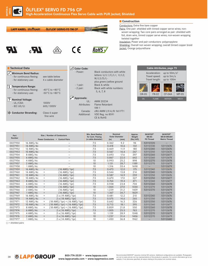
800-774-3539 • www.lappusa.comwww.lappcanada.com • www.lappmexico.com
38Recommended SKINTOP® assumes minimal OD variance. Additional configurations are available. Photographs are not to scale and are not true representations of the products in question. For current information go to our website. If not otherwise specified, all values relating to the product are nominal values.
MO
TOR
& D
RIV
E ÖLFLEX® SERVO FD 796 CPHigh-Acceleration Continuous Flex Servo Cable with PUR Jacket; Shielded
Cable Attributes, page 73
Acceleration:Travel speed:Travel length:
up to 50m/s2
up to 5m/sup to 100m
OR-05 FR-02 CF-04A MP-05
OIL FLAME MOTION MECH
Conductors: Extra fine bare copperPairs: One pair: shielded with tinned copper serve wires; non-
woven wrapping; Two core pairs arranged as pair: shielded with foil, drain wire, tinned copper serve wires; non-woven wrapping twisted together
Insulation: Power and pair conductors: polypropyleneShielding: Overall non woven wrapping; overall tinned copper braidJacket: Orange polyurethane
Construction
Technical Data
Minimum Bend Radius: - for continuous flexing: see table below - for stationary use: 4 x cable diameter
Temperature Range: - for continuous flexing: -40°C to +80°C - for stationary use: -50°C to +80°C
Nominal Voltage: - UL/CSA: 1000V - IEC U0/U: 600/1000V
Conductor Stranding: C lass 6 super fine wire
Color Code: - Power: Black conductors with white
letters: U/L1/C/L+; V/L2; W/L3/D/L - plus green/yellow ground
- 1 pair: Black & white - 2 pair: B lack with white numbers:
5, 6, 7, 8
Approvals: UL: AWM 20234 Attributes: Flame Retardant VW-1 Canada: cRU AWM I/II A/B 1kV FT1 Additional: VDE Reg. no 8591 CE & RoHS
( ) = shielded pairs
PartNumber
Size / Number of Conductors Min. Bend Radiusfor Cont. Flexing
(x cable diameter)
Nominal Outer Diameter
Approx. Weight
(lbs/mft)
SKINTOP® MS-SC
PG Thread
SKINTOP®
MS-M BRUSHMetric ThreadPower Conductors + Control Pairs (in) (mm)
0027950 16 AWG/4c — 7.5 0.362 9.2 94 53112220 —0027951 14 AWG/4c — 7.5 0.418 10.6 132 53112230 531126760027952 12 AWG/4c — 7.5 0.469 11.9 180 53112240 531126760027953 10 AWG/4c — 7.5 0.567 14.4 267 53112250 531126760027954 8 AWG/4c — 7.5 0.693 17.6 397 53112260 531126770027955 6 AWG/4c — 7.5 0.867 22.0 642 53112260 531126780027956 4 AWG/4c — 10 0.993 25.2 898 53112270 531126780027957 2 AWG/4c — 10 1.131 28.7 1189 53112270 531126790027958 1 AWG/4c — 10 1.316 33.4 1658 — 531126790027959 16 AWG/4c + (16 AWG/1pr) 7.5 0.473 12.0 175 53112240 531126760027960 14 AWG/4c + (16 AWG/1pr) 7.5 0.544 13.8 214 53112240 531126760027961 12 AWG/4c + (16 AWG/1pr) 7.5 0.587 14.9 259 53112250 531126760027962 10 AWG/4c + (16 AWG/1pr) 7.5 0.670 17.0 327 53112250 531126770027963 8 AWG/4c + (16 AWG/1pr) 7.5 0.764 19.4 471 53112260 531126770027964 6 AWG/4c + (16 AWG/1pr) 7.5 0.938 23.8 704 53112260 531126780027965 4 AWG/4c + (16 AWG/1pr) 10 1.064 27.0 1030 53112270 531126780027966 2 AWG/4c + (16 AWG/1pr) 10 1.229 31.2 1409 53112270 531126790027967 1 AWG/4c + (16 AWG/1pr) 10 1.367 34.7 1829 — 531126790027969 16 AWG/4c + 2 x (19 AWG/1pr) 7.5 0.481 12.2 210 53112240 531126760027970 14 AWG/4c + 2 x (18 AWG/1pr) 7.5 0.575 14.6 265 53112250 531126760027971 12 AWG/4c + (18 AWG/1pr) + (16 AWG/1pr) 7.5 0.642 16.3 326 53112250 531126760027972 10 AWG/4c + (18 AWG/1pr) + (16 AWG/1pr) 7.5 0.713 18.1 395 53112260 531126770027973 8 AWG/4c + (18 AWG/1pr) + (16 AWG/1pr) 7.5 0.859 21.8 550 53112260 531126780027974 6 AWG/4c + 2 x (16 AWG/1pr) 7.5 1.005 25.5 763 53112270 531126780027975 4 AWG/4c + 2 x (16 AWG/1pr) 10 1.139 28.9 1048 53112270 531126790027976 2 AWG/4c + 2 x (16 AWG/1pr) 10 1.237 31.4 1406 53112270 531126790027977 1 AWG/4c + 2 x (14 AWG/1pr) 10 1.450 36.8 1962 — 53112680
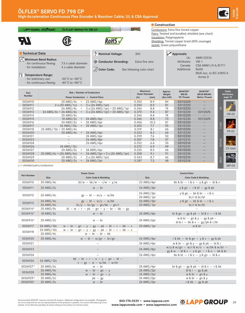
800-774-3539 • www.lappusa.comwww.lappcanada.com • www.lappmexico.com
39Recommended SKINTOP® assumes minimal OD variance. Additional configurations are available. Photographs are not to scale and are not true representations of the products in question. For current information go to our website. If not otherwise specified, all values relating to the product are nominal values.
MO
TOR &
DRIV
E
( ) = shielded pairs/conductors
Technical Data
Cable Attributes,
page 73
OIL
OR-05
FLAM
E
FR-02
MO
TIO
N
CF-04A
MEC
H
MP-05
Minimum Bend Radius: - for continuous flexing: 7.5 x cable diameter - for installation: 4 x cable diameter
Temperature Range: - for stationary use: -50°C to +80°C - for continuous flexing: -40°C to +80°C
Nominal Voltage: 30V
Conductor Stranding: Extra fine wire
Color Code: See following color chart
Approvals: UL: AWM 20236 Attributes: VW-1 Canada: CSA AWM I/II A/B FT1 Additional: RoHS M UD acc. to IEC 61892-4
Annex D
Conductors: Extra fine tinned copperPairs: Twisted and bundled; shielded (see chart)Insulation: PolypropyleneShielding: Tinned copper braid (85% coverage)Jacket: Green polyurethane
High-Acceleration Continuous Flex Encoder & Resolver Cable; UL & CSA ApprovalÖLFLEX® SERVO FD 798 CP
Construction
Part NumberPower Cores Control Pairs
Size Color Code & Shielding Size Color Code & Shielding
0036910 20 AWG/4c bl/w — bk/w — r/w — y/w 22 AWG/4pr bk & br — r & o — y & gn — bl & v
0036911 20 AWG/2c w — br 26 AWG/3pr y & gn — r & bl — gy & pk
0036912 26 AWG/4c gy — bl — w/y — w/bk26 AWG/3pr y & gn — bk & br — r & o20 AWG/1pr br/r & br/bl
003691326 AWG/4c gy — bl — w/y — w/bk 26 AWG/3pr y & gn — bk & br — r & o26 AWG/4c br/y — br/gy — gn/bk — gn/r 20 AWG/1pr br/r & br/bl
0036914* 20 AWG/9c bl — w — r — pk — gn — y — br — bk — gy —
0036915* 18 AWG/2c w — br 24 AWG/4pr br & gn — gy & pk — bl & v — r & bk
0036916* 20 AWG/2c w — br 24 AWG/6prw & br — gn & y — gy & pk —
bl & r — bk & v — gy/pk & r/bl 0036917 26 AWG/10c w — br — gn — y — gy — pk — bl — r — bk — v 20 AWG/1pr w & br
003691826 AWG/10c w — br — gn — y — gy — pk — bl — r — bk — v
—20 AWG/4c w — br — bl — bk
0036920 20 AWG/4c w — bl — w/gn — br/gn 26 AWG/4pr r & bk — br & gn — y & v — gy & pk
0036921 — 24 AWG/4pr w & br — gn & y — gy & pk — bl & r
0036923 — 26 AWG/8prw/y & w/gn — w/r & w/o — w/bk & w/br — gy & w — bl & v — y & gn — r & o — bk & br
0036924 — 26 AWG/4pr bk & br — r & o — y & gn — bl & v
0036926 26 AWG/12cbk — br — r — o — y — gn — bl —
v — gy — w — w/bk — w/br—
0036927* 20 AWG/2c w — br 24 AWG/4pr br & gn — gy & pk — bl & v — r & bk
003692826 AWG/4c w — br — gn — y 26 AWG/2pr bl & r — gy & pk20 AWG/4c w — br — gn — y 26 AWG/2pr w & br — gn & y
0036929* 20 AWG/2c pk — gy 24 AWG/2pr w & br — gn & y0036930* 20 AWG/2c w — br 24 AWG/2pr r & bk — gy & pk
PartNumber
Size / Number of Conductors Maximum Outer Diameter
Approx. Weight
(lbs/mft)
SKINTOP® MS-SC
PG Thread
SKINTOP®
MS-M BRUSHMetric ThreadPower Conductors + Control Pairs (in) (mm)
0036910 20 AWG/4c + 22 AWG/4pr 0.350 8.9 84 53112220 —0036911 2 x (20 AWG/1c) + 3 x (26 AWG/1pr) 0.350 8.9 81 53112220 —0036912 26 AWG/4c + 3 x (26 AWG/1pr) + 20 AWG/1pr 0.346 8.8 74 53112220 —0036913 26 AWG/4c + 26 AWG/4c + 3 x (26 AWG/1pr) + 20 AWG/1pr 0.370 9.4 87 53112220 531126760036914 20 AWG/9c — 0.346 8.8 74 53112220 —0036915 18 AWG/2c + 24 AWG/4pr 0.346 8.8 73 53112230 531126760036916 20 AWG/2c + 24 AWG/6pr 0.406 10.3 81 53112220 —0036917 26 AWG/10c + 20 AWG/1pr 0.303 7.7 55 53112220 —0036918 26 AWG/10c + 20 AWG/4c — 0.319 8.1 66 53112220 —0036920 20 AWG/4c + 26 AWG/4pr 0.323 8.2 64 53112220 —0036921 — 24 AWG/4pr 0.299 7.6 50 53112220 —0036923 — 26 AWG/8pr 0.307 7.8 57 53112210 —0036924 — 26 AWG/4pr 0.252 6.4 35 53112210 —0036926 24 AWG/12c — 0.272 6.9 49 53112210 —0036927 20 AWG/2c + 24 AWG/4pr 0.335 8.5 66 53112220 —0036928 20 AWG/4c + (26 AWG/4c) + 26 AWG/2pr + 2 x (26 AWG/1pr) 0.358 9.1 91 53112220 —0036929 20 AWG/2c + 2 x (24 AWG/1pr) 0.343 8.7 66 53112210 —0036930 20 AWG/2c + 24 AWG/2pr 0.287 7.3 48 53112210 —
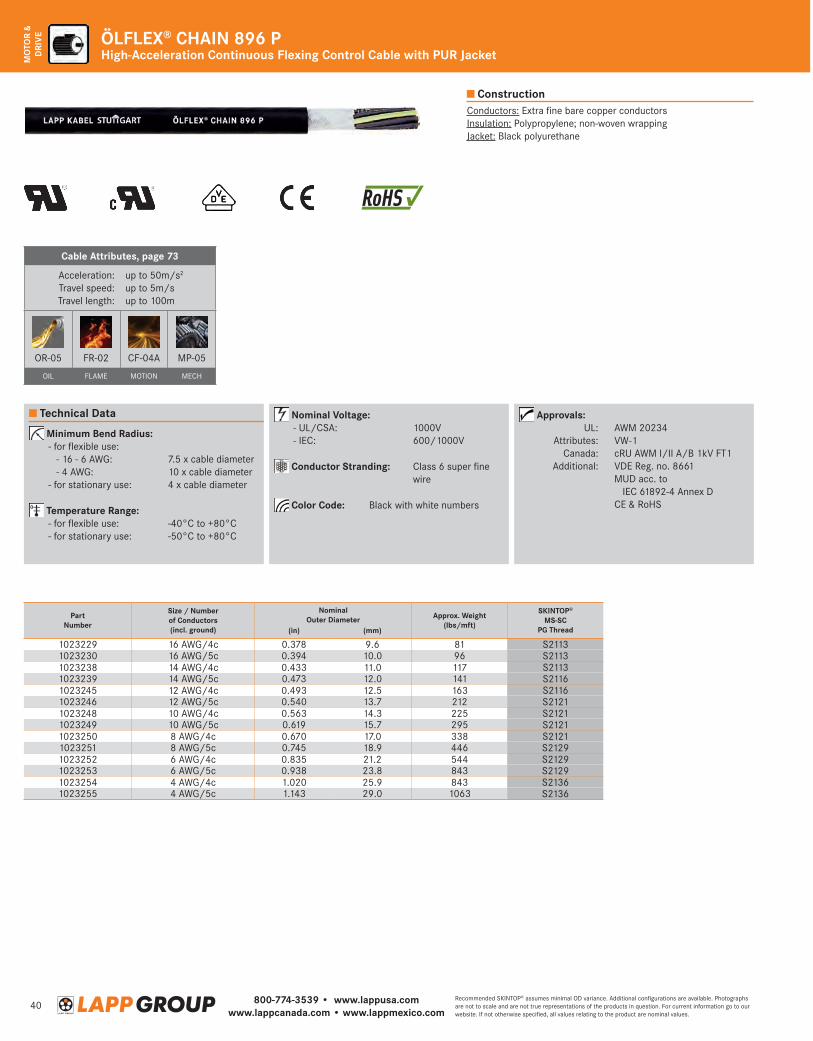
800-774-3539 • www.lappusa.comwww.lappcanada.com • www.lappmexico.com
40Recommended SKINTOP® assumes minimal OD variance. Additional configurations are available. Photographs are not to scale and are not true representations of the products in question. For current information go to our website. If not otherwise specified, all values relating to the product are nominal values.
MO
TOR
& D
RIV
E ÖLFLEX® CHAIN 896 PHigh-Acceleration Continuous Flexing Control Cable with PUR Jacket
Construction
Technical Data
Minimum Bend Radius: -forflexibleuse: -16-6AWG: 7.5xcablediameter -4AWG: 10xcablediameter -forstationaryuse: 4xcablediameter
Temperature Range: -forflexibleuse: -40°Cto+80°C -forstationaryuse: -50°Cto+80°C
Nominal Voltage: -UL/CSA: 1000V -IEC: 600/1000V
Conductor Stranding: Class6superfinewire
Color Code: Blackwithwhitenumbers
Approvals: UL: AWM20234 Attributes: VW-1 Canada: cRUAWMI/IIA/B1kVFT1 Additional: VDEReg.no.8661 MUDacc.to
IEC61892-4AnnexD CE&RoHS
Conductors:ExtrafinebarecopperconductorsInsulation:Polypropylene;non-wovenwrappingJacket:Blackpolyurethane
PartNumber
Size / Number of Conductors(incl. ground)
Nominal Outer Diameter Approx. Weight
(lbs/mft)
SKINTOP® MS-SC
PG Thread(in) (mm)
1023229 16AWG/4c 0.378 9.6 81 S21131023230 16AWG/5c 0.394 10.0 96 S21131023238 14AWG/4c 0.433 11.0 117 S21131023239 14AWG/5c 0.473 12.0 141 S21161023245 12AWG/4c 0.493 12.5 163 S21161023246 12AWG/5c 0.540 13.7 212 S21211023248 10AWG/4c 0.563 14.3 225 S21211023249 10AWG/5c 0.619 15.7 295 S21211023250 8AWG/4c 0.670 17.0 338 S21211023251 8AWG/5c 0.745 18.9 446 S21291023252 6AWG/4c 0.835 21.2 544 S21291023253 6AWG/5c 0.938 23.8 843 S21291023254 4AWG/4c 1.020 25.9 843 S21361023255 4AWG/5c 1.143 29.0 1063 S2136
Cable Attributes, page 73
Acceleration:Travelspeed:Travellength:
upto50m/s2
upto5m/supto100m
OR-05 FR-02 CF-04A MP-05
OIL FLAME MOTION MECH
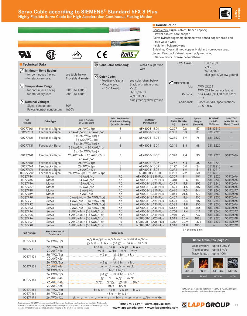
800-774-3539 • www.lappusa.comwww.lappcanada.com • www.lappmexico.com
41Recommended SKINTOP® assumes minimal OD variance. Additional configurations are available. Photographs are not to scale and are not true representations of the products in question. For current information go to our website. If not otherwise specified, all values relating to the product are nominal values.
MO
TOR &
DRIV
EServo Cable according to SIEMENS® Standard 6FX 8 PlusHighly Flexible Servo Cable for High-Acceleration Continuous Flexing Motion
Technical Data
Minimum Bend Radius: -forcontinuousflexing: seetablebelow -forstationaryuse: 4xcablediameter
Temperature Range: -forcontinuousflexing: -20°Cto+60°C -forstationaryuse: -50°Cto+80°C
Nominal Voltage: -Signalconductors: 30V -Power/controlconductors: 1000V
Conductor Stranding: Class6superfinewire
Color Code: -Feedback/signal: seecolorchartbelow -Motor/servo: Blackwithwhiteprint: -16-14AWG: V/L2
U/L1/C/L+ W/L3/D/L- plusgreen/yellowground
-12-1AWG: U/L1/C/L+ V/L2 W/L3/D/L- plusgreen/yellowground
Approvals: UL: AWM21223 AWM20236(sensorleads) Canada: CSAAWMI/IIA/B1kV80°C
FT1 Additional: BasedonVDEspecifications CE&RoHS
Conductors:Signalcables:tinnedcopper; Powercables:barecopper
Pairs:Twistedtogether;shieldedwithtinnedcopperbraidandnon-wovenwrap
Insulation:PolypropyleneShielding:Overalltinnedcopperbraidandnon-wovenwrapJacket:Feedback/signal:greenpolyurethane; Servo/motor:orangepolyurethane
Construction
SIEMENS®isaregisteredtrademarkofSIEMENSAG.SIEMENSpartnumbersaresuppliedforinformationalpurposesonly.
Part Number Size / Number of Conductors Color Code
00277101 26AWG/8prw/y&w/gn—w/r&w/o—w/bk&w/br— gy&w—bl&v—y&gn—r&o—bk&br
0027711122AWG/4pr br&bk—r&o—y&gn—bl&v20AWG/4c w/bl—w/bk—w/r—w/y
0027712126AWG/3pr y&gn—bk&br—r&o20AWG/2c bk—r
0027713126AWG/3pr y&gn—bk&br—r&o26AWG/4c gy—bl—w/y—w/bk20AWG/1pr br/r&br/bl
00277141
26AWG/3pr y&gn—bk&br—r&o26AWG/4c gy—bl—w/y—w/bk26AWG/4c br/y—br/gy—gn/bk—gn/r20AWG/2c br/r—br/bl
00277151 26AWG/4pr bk&br—r&o—y&gn—bl&v00277161 26AWG/2pr r&o—bk&br00277171 26AWG/12c bk—br—r—o—y—gn—bl—v—gy—w—w/bk—w/br
PartNumber Cable Type Size / Number
of Conductors
Min. Bend RadiusContinuous Flexing(x cable diameter)
SIEMENS® Part Number
Nominal Outer Diameter
Approx. Weight
(lbs/mft)
SKINTOP® MS-SC
PG Thread
SKINTOP®
MS-M BRUSHMetric Thread(in) (mm)
00277101 Feedback/Signal 26AWG/8pr 8 6FX8008-1BD11 0.307 7.8 57 53112210 —00277111 Feedback/Signal 22AWG/4pr+20AWG/4c 8 6FX8008-1BD21 0.350 8.9 81 53112220 —
00277121 Feedback/Signal3x(26AWG/1pr)+ 2x(20AWG/1c)
8 6FX8008-1BD31 0.350 8.9 76 53112220 —
00277131 Feedback/Signal3x(26AWG/1pr)+
26AWG/4c+20AWG/1pr8 6FX8008-1BD41 0.346 8.8 68 53112220 —
00277141 Feedback/Signal3x(26AWG/1pr)+
26AWG/4c+20AWG/2c+ 26AWG/4c
8 6FX8008-1BD51 0.370 9.4 93 53112220 53112676
00277151 Feedback/Signal 26AWG/4pr 8 6FX8008-1BD61 0.252 6.4 36 53112220 —00277161 Feedback/Signal 26AWG/2pr 8 6FX8008-1BD71 0.197 5.0 24 53112210 —00277171 Feedback/Signal 26AWG/12c 8 6FX8008-1BD81 0.272 6.9 51 53112210 —00277992 Feedback/Signal 26AWG/2pr+21AWG/1pr 8 6FX8008-2DC00 0.283 7.2 50 53112210 —0027784 Motor 16AWG/4c 7.5 6FX8008-1BB11-Plus 0.359 9.1 101 53112220 531126760027785 Motor 14AWG/4c 7.5 6FX8008-1BB21-Plus 0.418 10.6 148 53112230 531126760027786 Motor 12AWG/4c 7.5 6FX8008-1BB31-Plus 0.469 11.9 202 53112240 531126760027787 Motor 10AWG/4c 7.5 6FX8008-1BB41-Plus 0.571 14.5 302 53112250 531126760027788 Motor 8AWG/4c 7.5 6FX8008-1BB51-Plus 0.690 17.5 444 53112260 531126770027789 Motor 6AWG/4c 7.5 6FX8008-1BB61-Plus 0.851 21.6 679 53112260 531126780027790 Servo 16AWG/4c+(16AWG/1pr) 7.5 6FX8008-1BA11-Plus 0.457 11.6 155 53112230 531126760027791 Servo 14AWG/4c+(16AWG/1pr) 7.5 6FX8008-1BA21-Plus 0.528 13.4 202 53112240 531126760027792 Servo 12AWG/4c+(16AWG/1pr) 7.5 6FX8008-1BA31-Plus 0.583 14.8 255 53112250 531126760027793 Servo 10AWG/4c+(16AWG/1pr) 7.5 6FX8008-1BA41-Plus 0.662 16.8 356 53112250 531126760027794 Servo 8AWG/4c+(16AWG/1pr) 7.5 6FX8008-1BA51-Plus 0.764 19.4 514 53112260 531126770027795 Servo 6AWG/4c+(16AWG/1pr) 7.5 6FX8008-1BA61-Plus 0.910 23.1 732 53112660 531126780027796 Servo 4AWG/4c+(16AWG/1pr) 10 6FX8008-1BA25-Plus 1.048 26.6 1028 53112270 531126780027797 Servo 2AWG/4c+(16AWG/1pr) 10 6FX8008-1BA35-Plus 1.217 30.9 1371 53112270 531126790027798 Servo 1AWG/4c+(16AWG/1pr) 10 6FX8008-1BA50-Plus 1.340 34.0 1855 — 53112679
()=shieldedpairs
Cable Attributes, page 73
Acceleration:Travelspeed:Travellength:
upto50m/s2
upto5m/supto100m
OR-05 FR-02 CF-04A MP-05
OIL FLAME MOTION MECH
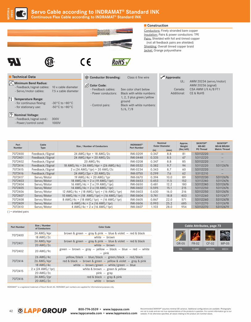
800-774-3539 • www.lappusa.comwww.lappcanada.com • www.lappmexico.com
42Recommended SKINTOP® assumes minimal OD variance. Additional configurations are available. Photographs are not to scale and are not true representations of the products in question. For current information go to our website. If not otherwise specified, all values relating to the product are nominal values.
MO
TOR
& D
RIV
E Servo Cable according to INDRAMAT® Standard INKContinuous Flex Cable according to INDRAMAT® Standard INK
Construction
Technical Data
Cable Attributes, page 73
OR-05 FR-02 CF-02 MP-05
OIL FLAME MOTION MECH
Conductor Stranding: Class6finewire
Color Code: -Feedbackcables: Seecolorchartbelow -Powerconductors: Blackwithwhitenumbers:
1,2,3plusgreen/yellowground
-Controlpairs: Blackwithwhitenumbers:5/6,7/8
Minimum Bend Radius: -Feedback/signalcables: 10xcablediameter -Servo/motorcables: 7.5xcablediameter
Temperature Range: -forcontinuousflexing: -30°Cto+80°C -forstationaryuse: -50°Cto+80°C
Nominal Voltage: -Feedback/signalcond.: 300V -Power/controlcond: 1000V
Approvals: UL: AWM20234(servo/motor) AWM20236(signal) Canada: CSAAWMI/IIA/BFT1 Additional: CE&RoHS
Conductors:FinelystrandedbarecopperInsulation:Pairs&powerconductors:TPEPairs:Shieldedwithfoilandtinnedcopper (notallfeedbackpairsareshielded)
Shielding:OveralltinnedcopperbraidJacket:Orangepolyurethane
Part Number Size / Number of Conductors Color Code
707240024AWG/4pr brown&green—gray&pink—blue&violet—red&black18AWG/2c white—brown
707240124AWG/4pr brown&green—gray&pink—blue&violet—red&black20AWG/2c white—brown
7072402 20AWG/9cgreen—brown—gray—yellow—black—blue—red—white
—pink
707241426AWG/4c yellow/black—blue/black—green/black—red/black26AWG/4pr red&black—brown&green—yellow&violet—gray&pink18AWG/4c white—brown/green—white/green—blue
70724152x(24AWG/1pr) white&brown—green&yellow
20AWG/2c pink—gray
707241624AWG/2pr red&black—gray&pink20AWG/2c white—brown
INDRAMAT ®isaregisteredtrademarkofBoschRerothAG.INDRAMATpartnumbersaresuppliedforinformationalpurposesonly.
()=shieldedpairs
PartNumber
CableType Size / Number of Conductors INDRAMAT®
Part Number
Nominal Outer Diameter
Approx. Weight
(lbs/mft)
SKINTOP® MS-MC
PG Thread
SKINTOP® MS-M BRUSHMetric Thread(in) (mm)
7072400 Feedback/Signal 24AWG/4pr+18AWG/2c INK-0209 0.347 8.8 81 53112220 —7072401 Feedback/Signal 24AWG/4pr+20AWG/2c INK-0448 0.335 8.5 67 53112220 —7072402 Feedback/Signal 20AWG/9c INK-0208 0.347 8.8 85 53112220 —7072414 Feedback/Signal 18AWG/4c+26AWG/4pr+(26AWG/4c) INK-0532 0.382 9.7 94 53112220 531126767072415 Feedback/Signal 2x(24AWG/1pr)+20AWG/2c INK-0234 0.343 8.7 60 53112220 —7072416 Feedback/Signal 24AWG/2pr+20AWG/2c INK-0750 0.299 7.6 62 53112210 —7072417 Servo/Motor 19AWG/4c+20AWG/1pr INK-0670 0.394 10.0 89 53112230 531126767072403 Servo/Motor 18AWG/4c+2x(19AWG/1pr) INK-0653 0.453 11.5 152 53112240 531126767072404 Servo/Motor 16AWG/4c+2x(19AWG/1pr) INK-0650 0.481 12.2 180 53112240 531126767072405 Servo/Motor 14AWG/4c+2x(18AWG/1pr) INK-0602 0.595 15.1 215 53112250 531126767072406 Servo/Motor 12AWG/4c+(18AWG/1pr)+(16AWG/1pr) INK-0603 0.630 16.0 316 53112250 531126767072407 Servo/Motor 10AWG/4c+(18AWG/1pr)+(16AWG/1pr) INK-0604 0.741 18.8 403 53112260 531126777072408 Servo/Motor 8AWG/4c+(18AWG/1pr)+(16AWG/1pr) INK-0605 0.867 22.0 571 53112260 531126787072409 Servo/Motor 6AWG/4c+2x(16AWG/1pr) INK-0606 0.993 25.2 685 53112270 531126787072410 Servo/Motor 4AWG/4c+2x(16AWG/1pr) INK-0607 1.103 28.0 954 53112270 53112679
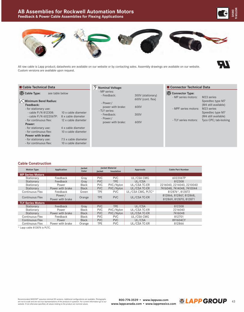
800-774-3539 • www.lappusa.comwww.lappcanada.com • www.lappmexico.com
43Recommended SKINTOP® assumes minimal OD variance. Additional configurations are available. Photographs are not to scale and are not true representations of the products in question. For current information go to our website. If not otherwise specified, all values relating to the product are nominal values.
MO
TOR &
DRIV
EFeedback & Power Cable Assemblies for Flexing ApplicationsAB Assemblies for Rockwell Automation Motors
Cable Type: see table below
Minimum Bend Radius: Feedback: - for stationary use: - cable P/N 812308: 10 x cable diameter - cable P/N 602206TP: 8 x cable diameter - for continuous flex: 12 x cable diameter Power: - for stationary use: 4 x cable diameter - for continuous flex: 10 x cable diameter Power with brake: - for stationary use: 7.5 x cable diameter - for continuous flex: 10 x cable diameter
Nominal Voltage: - MP series: - Feedback: 300V (stationary)
600V (cont. flex) - Power/
power with brake: 600V - TLY series: - Feedback: 300V - Power/
power with brake: 600V
Connector Type: - MP series motors: M23 series
Speedtec type M7 (M4 still available)
- MPF series motors: M23 series Speedtec type M7 (M4 still available)
- TLY series motors: Tyco CPC; tab-locking
Cable Technical Data Connector Technical Data
Motion Type Application Jacket Color
Jacket MaterialApprovals Cable Part Number
Jacket Insulation
MP Series MotorsStationary Feedback Gray PVC PVC UL/CSA CMG 602206TPStationary Feedback Gray PVC TPE UL/CSA 812308Stationary Power Black PVC PVC/Nylon UL/CSA TC-ER 2216040, 2214040, 2210040Stationary Power with brake Black PVC PVC/Nylon UL/CSA TC-ER 7416048, 7414048, 7410044
Continuous Flex Feedback Green TPE PVC UL/CSA CMG, PLTC* 812876*, 812872
Continuous FlexPower/
Power with brakeOrange TPE PVC UL/CSA TC-ER
812866, 812867, 812868, 812869, 812870, 812871
TLY Series MotorsStationary Feedback Gray PVC TPE UL/CSA 812308Stationary Power Black PVC PVC/Nylon UL/CSA TC-ER 2216040Stationary Power with brake Black PVC PVC/Nylon UL/CSA TC-ER 7416048
Continuous Flex Feedback Black PVC PVC UL/CSA CMG 812701Continuous Flex Power Black PVC PVC UL/CSA 891604CYContinuous Flex Power with brake Orange TPE PVC UL/CSA TC-ER 812866
* Lapp cable 812876 is PLTC.
All raw cable is Lapp product; datasheets are available on our website or by contacting sales. Assembly drawings are available on our website. Custom versions are available upon request.
Cable Construction
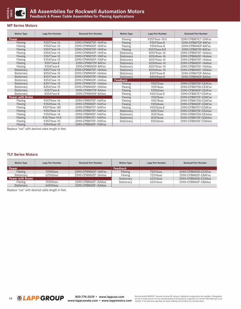
800-774-3539 • www.lappusa.comwww.lappcanada.com • www.lappmexico.com
44Recommended SKINTOP® assumes minimal OD variance. Additional configurations are available. Photographs are not to scale and are not true representations of the products in question. For current information go to our website. If not otherwise specified, all values relating to the product are nominal values.
MO
TOR
& D
RIV
E AB Assemblies for Rockwell Automation MotorsFeedback & Power Cable Assemblies for Flexing Applications
Motion Type Lapp Part Number Rockwell Part Number
PowerFlexing 93577xxx-16 2090-CPWM7DF-16AFxxFlexing 93547xxx-16 2090-CPWM4DF-16AFxxFlexing 93577xxx-14 2090-CPWM7DF-14AFxxFlexing 93547xxx-14 2090-CPWM4DF-14AFxxFlexing 93577xxx-10 2090-CPWM7DF-10AFxxFlexing 93547xxx-10 2090-CPWM4DF-10AFxxFlexing 93577xxx-8 2090-CPWM7DF-8AFxxFlexing 93547xxx-8 2090-CPWM4DF-8AFxx
Stationary 83577xxx-16 2090-CPWM7DF-16AAxxStationary 83547xxx-16 2090-CPWM4DF-16AAxxStationary 83577xxx-14 2090-CPWM7DF-14AAxxStationary 83547xxx-14 2090-CPWM4DF-14AAxxStationary 83577xxx-10 2090-CPWM7DF-10AAxxStationary 83547xxx-10 2090-CPWM4DF-10AAxxStationary 83577xxx-8 2090-CPWM7DF-8AAxxStationary 83547xxx-8 2090-CPWM4DF-8AAxx
Power with BrakeFlexing 93579xxx-16 2090-CPBM7DF-16AFxxFlexing 93549xxx-16 2090-CPBM4DF-16AFxxFlexing 93579xxx-16E 2090-CPBM7E7-16AFxxFlexing 93579xxx-14 2090-CPBM7DF-14AFxxFlexing 93549xxx-14 2090-CPBM4DF-14AFxxFlexing 93579xxx-14-E 2090-CPBM7E7-14AFxxFlexing 93579xxx-10 2090-CPBM7DF-10AFxxFlexing 93549xxx-10 2090-CPBM4DF-10AFxx
Motion Type Lapp Part Number Rockwell Part Number
Flexing 93579xxx-10-E 2090-CPBM7E7-10AFxxFlexing 93579xxx-8 2090-CPBM7DF-8AFxxFlexing 93549xxx-8 2090-CPBM4DF-8AFxxFlexing 93579xxx-8-E 2090-CPBM7EF-8AFxx
Stationary 83579xxx-16 2090-CPBM7DF-16AAxxStationary 83549xxx-16 2090-CPBM4DF-16AAxxStationary 83579xxx-14 2090-CPBM7DF-14AAxxStationary 83549xxx-14 2090-CPBM4DF-14AAxxStationary 83579xxx-10 2090-CPBM7DF-10AAxxStationary 83549xxx-10 2090-CPBM4DF-10AAxxStationary 83579xxx-8 2090-CPBM7DF-8AAxxStationary 83549xxx-8 2090-CPBM4DF-8AAxx
FeedbackFlexing 93572xxx 2090-CFBM7DF-CEAFxxFlexing 93574xxx 2090-CFBM7DD-CEAFxxFlexing 93542xxx 2090-CFBM4DF-CEAFxxFlexing 93572xxx-E 2090-CFBM7E7-CEAFxxFlexing 93576xxx 2090-CFBM7DF-CDAFxxFlexing 93578xxx 2090-CFBM7DD-CDAFxxFlexing 93546xxx 2090-CFBM4DF-CDAFxxFlexing 93576xxx-E 2090-CFBM7E7-CDAFxx
Stationary 83572xxx 2090-CFBM7DF-CEAAxxStationary 83574xxx 2090-CFBM7DD-CEAAxxStationary 83576xxx 2090-CFBM7DF-CDAAxxStationary 83546xxx 2090-CFBM4DF-CDAAxx
Motion Type Lapp Part Number Rockwell Part Number
PowerFlexing 72505xxx 2090-CPWM6DF-16AFxx
Stationary 62505xxx 2090-CPWM6DF-16AAxxPower with Brake
Flexing 74505xxx 2090-CPBM6DF-16AAxxStationary 64505xxx 2090-CPBM6DF-16AAxx
Motion Type Lapp Part Number Rockwell Part Number
FeedbackFlexing 72515xxx 2090-CFBM6DD-CCAFxxFlexing 72514xxx 2090-CFBM6DF-CBAFxx
Stationary 62515xxx 2090-CFBM6DD-CCAAxxStationary 62514xxx 2090-CFBM6DF-CBAAxx
TLY Series Motors
MP Series Motors
Replace “xxx” with desired cable length in feet.
Replace “xxx” with desired cable length in feet.
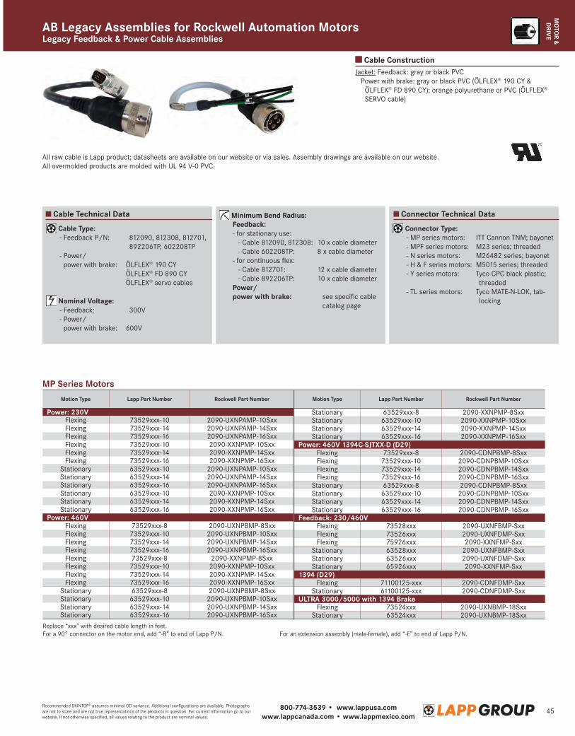
800-774-3539 • www.lappusa.comwww.lappcanada.com • www.lappmexico.com
45Recommended SKINTOP® assumes minimal OD variance. Additional configurations are available. Photographs are not to scale and are not true representations of the products in question. For current information go to our website. If not otherwise specified, all values relating to the product are nominal values.
MO
TOR &
DRIV
EAB Legacy Assemblies for Rockwell Automation MotorsLegacy Feedback & Power Cable Assemblies
Cable ConstructionJacket: Feedback: gray or black PVC
P ower with brake: gray or black PVC (ÖLFLEX® 190 CY & ÖLFLEX® FD 890 CY); orange polyurethane or PVC (ÖLFLEX® SERVO cable)
Motion Type Lapp Part Number Rockwell Part Number
Power: 230VFlexing 73529xxx-10 2090-UXNPAMP-10SxxFlexing 73529xxx-14 2090-UXNPAMP-14SxxFlexing 73529xxx-16 2090-UXNPAMP-16SxxFlexing 73529xxx-10 2090-XXNPMP-10SxxFlexing 73529xxx-14 2090-XXNPMP-14SxxFlexing 73529xxx-16 2090-XXNPMP-16Sxx
Stationary 63529xxx-10 2090-UXNPAMP-10SxxStationary 63529xxx-14 2090-UXNPAMP-14SxxStationary 63529xxx-16 2090-UXNPAMP-16SxxStationary 63529xxx-10 2090-XXNPMP-10SxxStationary 63529xxx-14 2090-XXNPMP-14SxxStationary 63529xxx-16 2090-XXNPMP-16Sxx
Power: 460VFlexing 73529xxx-8 2090-UXNPBMP-8SxxFlexing 73529xxx-10 2090-UXNPBMP-10SxxFlexing 73529xxx-14 2090-UXNPBMP-14SxxFlexing 73529xxx-16 2090-UXNPBMP-16SxxFlexing 73529xxx-8 2090-XXNPMP-8SxxFlexing 73529xxx-10 2090-XXNPMP-10SxxFlexing 73529xxx-14 2090-XXNPMP-14SxxFlexing 73529xxx-16 2090-XXNPMP-16Sxx
Stationary 63529xxx-8 2090-UXNPBMP-8SxxStationary 63529xxx-10 2090-UXNPBMP-10SxxStationary 63529xxx-14 2090-UXNPBMP-14SxxStationary 63529xxx-16 2090-UXNPBMP-16Sxx
Motion Type Lapp Part Number Rockwell Part Number
Stationary 63529xxx-8 2090-XXNPMP-8SxxStationary 63529xxx-10 2090-XXNPMP-10SxxStationary 63529xxx-14 2090-XXNPMP-14SxxStationary 63529xxx-16 2090-XXNPMP-16Sxx
Power: 460V 1394C-SJTXX-D (D29)Flexing 73529xxx-8 2090-CDNPBMP-8SxxFlexing 73529xxx-10 2090-CDNPBMP-10SxxFlexing 73529xxx-14 2090-CDNPBMP-14SxxFlexing 73529xxx-16 2090-CDNPBMP-16Sxx
Stationary 63529xxx-8 2090-CDNPBMP-8SxxStationary 63529xxx-10 2090-CDNPBMP-10SxxStationary 63529xxx-14 2090-CDNPBMP-14SxxStationary 63529xxx-16 2090-CDNPBMP-16Sxx
Feedback: 230/460VFlexing 73528xxx 2090-UXNFBMP-SxxFlexing 73526xxx 2090-UXNFDMP-SxxFlexing 75926xxx 2090-XXNFMP-Sxx
Stationary 63528xxx 2090-UXNFBMP-SxxStationary 63526xxx 2090-UXNFDMP-SxxStationary 65926xxx 2090-XXNFMP-Sxx
1394 (D29)Flexing 71100125-xxx 2090-CDNFDMP-Sxx
Stationary 61100125-xxx 2090-CDNFDMP-SxxULTRA 3000/5000 with 1394 Brake
Flexing 73524xxx 2090-UXNBMP-18SxxStationary 63524xxx 2090-UXNBMP-18Sxx
MP Series Motors
Replace “xxx” with desired cable length in feet.For a 90° connector on the motor end, add “-R” to end of Lapp P/N. For an extension assembly (male-female), add “-E” to end of Lapp P/N.
All raw cable is Lapp product; datasheets are available on our website or via sales. Assembly drawings are available on our website. All overmolded products are molded with UL 94 V-0 PVC.
Cable Type: - Feedback P/N: 812090, 812308, 812701,
892206TP, 602208TP - Power/
power with brake: ÖLFLEX® 190 CY ÖLFLEX® FD 890 CY Ö LFLEX® servo cables
Nominal Voltage: - Feedback: 300V - Power/
power with brake: 600V
Minimum Bend Radius: Feedback: - for stationary use: - Cable 812090, 812308: 10 x cable diameter - Cable 602208TP: 8 x cable diameter - for continuous flex: - Cable 812701: 12 x cable diameter - Cable 892206TP: 10 x cable diameter Power/
power with brake: see specific cable catalog page
Connector Type: - MP series motors: ITT Cannon TNM; bayonet - MPF series motors: M23 series; threaded - N series motors: M26482 series; bayonet - H & F series motors: M5015 series; threaded - Y series motors: T yco CPC black plastic;
threaded - TL series motors: T yco MATE-N-LOK, tab-
locking
Cable Technical Data Connector Technical Data
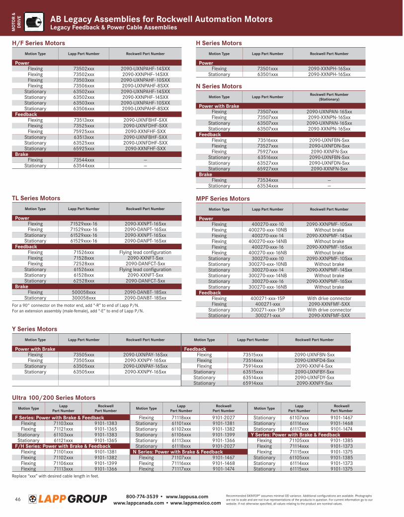
800-774-3539 • www.lappusa.comwww.lappcanada.com • www.lappmexico.com
46Recommended SKINTOP® assumes minimal OD variance. Additional configurations are available. Photographs are not to scale and are not true representations of the products in question. For current information go to our website. If not otherwise specified, all values relating to the product are nominal values.
MO
TOR
& D
RIV
E
Legacy Feedback & Power Cable AssembliesAB Legacy Assemblies for Rockwell Automation Motors
Motion Type Lapp Part Number Rockwell Part Number
PowerFlexing 73502xxx 2090-UXNPAHF-14SXXFlexing 73502xxx 2090-XXNPHF-14SXXFlexing 73503xxx 2090-UXNPAHF-10SXXFlexing 73506xxx 2090-UXNPAHF-8SXX
Stationary 63502xxx 2090-UXNPAHF-14SXXStationary 63502xxx 2090-XXNPHF-14SXXStationary 63503xxx 2090-UXNPAHF-10SXXStationary 63506xxx 2090-UXNPAHF-8SXX
FeedbackFlexing 73513xxx 2090-UXNFBHF-SXXFlexing 73525xxx 2090-UXNFDHF-SXXFlexing 75925xxx 2090-XXNFHF-SXX
Stationary 63513xxx 2090-UXNFBHF-SXXStationary 63525xxx 2090-UXNFDHF-SXXStationary 65925xxx 2090-XXNFHF-SXX
BrakeFlexing 73544xxx —
Stationary 63544xxx —
H/F Series MotorsMotion Type Lapp Part Number Rockwell Part Number
PowerFlexing 73501xxx 2090-XXNPH-16Sxx
Stationary 63501xxx 2090-XXNPH-16Sxx
H Series Motors
Motion Type Lapp Part Number Rockwell Part Number
PowerFlexing 71529xxx-16 2090-XXNPT-16SxxFlexing 71529xxx-16 2090-DANPT-16Sxx
Stationary 61529xxx-16 2090-XXNPT-16SxxStationary 61529xxx-16 2090-DANPT-16Sxx
FeedbackFlexing 71526xxx Flying lead configurationFlexing 71528xxx 2090-XXNFT-SxxFlexing 72528xxx 2090-DANFCT-Sxx
Stationary 61526xxx Flying lead configurationStationary 61528xxx 2090-XXNFT-SxxStationary 62528xxx 2090-DANFCT-Sxx
BrakeFlexing 500058xxx 2090-DANBT-18Sxx
Stationary 300058xxx 2090-DANBT-18Sxx
TL Series Motors
For a 90° connector on the motor end, add “-R” to end of Lapp P/N.For an extension assembly (male-female), add “-E” to end of Lapp P/N.
Motion Type Lapp Part Number Rockwell Part Number (Stationary)
Power with BrakeFlexing 73507xxx 2090-UXNPAN-16SxxFlexing 73507xxx 2090-XXNPN-16Sxx
Stationary 63507xxx 2090-UXNPAN-16SxxStationary 63507xxx 2090-XXNPN-16Sxx
FeedbackFlexing 73516xxx 2090-UXNFBN-SxxFlexing 73527xxx 2090-UXNFDN-SxxFlexing 75927xxx 2090-XXNFN-Sxx
Stationary 63516xxx 2090-UXNFBN-SxxStationary 63527xxx 2090-UXNFDN-SxxStationary 65927xxx 2090-XXNFN-Sxx
BrakeFlexing 73534xxx —
Stationary 63534xxx —
N Series Motors
Motion Type Lapp Part Number Rockwell Part Number
PowerFlexing 400270-xxx-10 2090-XXNPMF-10SxxFlexing 400270-xxx-10NB Without brakeFlexing 400270-xxx-14 2090-XXNPMF-14SxxFlexing 400270-xxx-14NB Without brakeFlexing 400270-xxx-16 2090-XXNPMF-16SxxFlexing 400270-xxx-16NB Without brake
Stationary 300270-xxx-10 2090-XXNPMF-10SxxStationary 300270-xxx-10NB Without brakeStationary 300270-xxx-14 2090-XXNPMF-14SxxStationary 300270-xxx-14NB Without brakeStationary 300270-xxx-16 2090-XXNPMF-16SxxStationary 300270-xxx-16NB Without brake
FeedbackFlexing 400271-xxx-15P With drive connectorFlexing 400271-xxx 2090-XXNFMF-SXX
Stationary 300271-xxx-15P With drive connectorStationary 300271-xxx 2090-XXNFMF-SXX
MPF Series Motors
Motion Type Lapp Part Number Rockwell Part Number
Power with BrakeFlexing 73505xxx 2090-UXNPAY-16SxxFlexing 73505xxx 2090-XXNPY-16Sxx
Stationary 63505xxx 2090-UXNPAY-16SxxStationary 63505xxx 2090-XXNPY-16Sxx
Y Series Motors
Motion Type Lapp Part Number
Rockwell Part Number
F Series: Power with Brake & FeedbackFlexing 71103xxx 9101-1383Flexing 71121xxx 9101-1365
Stationary 61103xxx 9101-1383Stationary 61121xxx 9101-1365
F/H Series: Power with Brake & FeedbackFlexing 71101xxx 9101-1381Flexing 71102xxx 9101-1382Flexing 71106xxx 9101-1399Flexing 71113xxx 9101-1366
Motion Type Lapp Part Number
Rockwell Part Number
Flexing 71118xxx 9101-2027Stationary 61101xxx 9101-1381Stationary 61102xxx 9101-1382Stationary 61106xxx 9101-1399Stationary 61113xxx 9101-1366Stationary 61118xxx 9101-2027
N Series: Power with Brake & FeedbackFlexing 71107xxx 9101-1467Flexing 71116xxx 9101-1468Flexing 71117xxx 9101-1474
Ultra 100/200 Series MotorsMotion Type Lapp
Part NumberRockwell
Part Number
Stationary 61107xxx 9101-1467Stationary 61116xxx 9101-1468Stationary 61117xxx 9101-1474
Y Series: Power with Brake & FeedbackFlexing 71105xxx 9101-1385Flexing 71114xxx 9101-1373Flexing 71115xxx 9101-1375
Stationary 61105xxx 9101-1385Stationary 61114xxx 9101-1373Stationary 61115xxx 9101-1375
Replace “xxx” with desired cable length in feet.
Motion Type Lapp Part Number Rockwell Part Number
FeedbackFlexing 73515xxx 2090-UXNFBN-SxxFlexing 73514xxx 2090-UXNFD4-SxxFlexing 75914xxx 2090-XXNF4-Sxx
Stationary 63515xxx 2090-UXNFBY-SxxStationary 63514xxx 2090-UXNFDY-SxxStationary 65914xxx 2090-XXNFY-Sxx
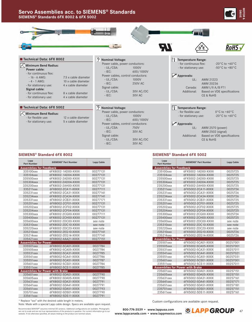
800-774-3539 • www.lappusa.comwww.lappcanada.com • www.lappmexico.com
47Recommended SKINTOP® assumes minimal OD variance. Additional configurations are available. Photographs are not to scale and are not true representations of the products in question. For current information go to our website. If not otherwise specified, all values relating to the product are nominal values.
MO
TOR &
DRIV
E
Technical Data: 6FX 8002
Technical Data: 6FX 5002
Minimum Bend Radius: Power cable: - for continuous flex: - 16 - 6 AWG: 7.5 x cable diameter - 4 - 1 AWG: 10 x cable diameter - for stationary use: 4 x cable diameter Signal cable: - for continuous flex: 8 x cable diameter - for stationary use: 4 x cable diameter
Minimum Bend Radius: - for flexible use: 12 x cable diameter - for stationary use: 5 x cable diameter
Nominal Voltage: Power cable, power conductors: - UL/CSA: 1000V - IEC: 600/1000V Power cables, control conductors: - UL/CSA: 1000V - IEC: 250V AC Signal cable: - UL/CSA: 30V AC/DC - IEC: 30V AC
Nominal Voltage: Power cable, power conductors: - UL/CSA: 1000V - IEC: 600/1000V Power cables, control conductors: - UL/CSA: 750V - IEC: 30V AC Signal cable: - UL/CSA: 30V AC/DC - IEC: 30V AC
Temperature Range: - for continuous flex: -20°C to +60°C - for stationary use: -50°C to +80°C
Approvals: UL: AWM 21223 AWM 20236 Canada: AWM I/II A/B FT1 Additional: Based on VDE specifications CE & RoHS
Temperature Range: - for flexible use: 0°C to +60°C - for stationary use: -20°C to +60°C
Approvals: UL: AWM 2570 (power) AWM 2502 (signal) Additional: Based on VDE specifications CE & RoHS
SIEMENS® Standards 6FX 8002 & 6FX 5002Servo Assemblies acc. to SIEMENS® Standards
Lapp Part Number SIEMENS® Part Number Lapp Cable
Assemblies for Feedback335100xxx 6FX8002-1AD00-XXXX 00277131335104xxx 6FX8002-1AD04-XXXX 00277131335500xxx 6FX8002-2AD00-XXXX 00277131335304xxx 6FX8002-2AD04-XXXX 00277131335200xxx 6FX8002-2AH00-XXXX 00277131335211xxx 6FX8002-2CA11-XXXX 00277111335231xxx 6FX8002-2CA31-XXXX 00277141335234xxx 6FX8002-2CA34-XXXX 00277141335331xxx 6FX8002-2CB31-XXXX 00277171335201xxx 6FX8002-2CF01-XXXX 00277131335202xxx 6FX8002-2CF02-XXXX 00277131335204xxx 6FX8002-2CF04-XXXX 00277131335300xxx 6FX8002-2CG00-XXXX 00277111335400xxx 6FX8002-2CH00-XXXX 00277131335600xxx 6FX8002-2DC00-XXXX see note335310xxx 6FX8002-2DC10-XXXX see note335220xxx 6FX8002-2DC20-XXXX see note335210xxx 6FX8002-2EQ10-XXXX 00277141335214xxx 6FX8002-2EQ14-XXXX 00277141335421xxx 6FX8002-4AA21-XXXX 00277151
Assemblies for Power335501xxx 6FX8002-5CA01-XXXX 0027784335505xxx 6FX8002-5CA05-XXXX 0027784335531xxx 6FX8002-5CA31-XXXX 0027785335541xxx 6FX8002-5CA41-XXXX 0027786335551xxx 6FX8002-5CA51-XXXX 0027787335601xxx 6FX8002-5CS01-XXXX 0027784335511xxx 6FX8002-5CS11-XXXX 0027785
Assemblies for Power with Brake335601xxx 6FX8002-5DA01-XXXX 0027790335605xxx 6FX8002-5DA05-XXXX 0027790335631xxx 6FX8002-5DA31-XXXX 0027791335641xxx 6FX8002-5DA41-XXXX 0027791335651xxx 6FX8002-5DA51-XXXX 0027793335701xxx 6FX8002-5DS01-XXXX 0027790335611xxx 6FX8002-5DS11-XXXX 0027791
Lapp Part Number SIEMENS® Part Number Lapp Cable
Assemblies for Feedback235100xxx 6FX5002-1AD00-XXXX 0025725235104xxx 6FX5002-1AD04-XXXX 0025725235500xxx 6FX5002-2AD00-XXXX 0025725235304xxx 6FX5002-2AD04-XXXX 0025725235200xxx 6FX5002-2AH00-XXXX 0025725235211xxx 6FX5002-2CA11-XXXX 0025724235231xxx 6FX5002-2CA31-XXXX 0025726235234xxx 6FX5002-2CA34-XXXX 0025726235331xxx 6FX5002-2CB31-XXXX 0025725235201xxx 6FX5002-2CF01-XXXX 0025725235202xxx 6FX5002-2CF02-XXXX 0025725235204xxx 6FX5002-2CF04-XXXX 0025725235300xxx 6FX5002-2CG00-XXXX 0025724235400xxx 6FX5002-2CH00-XXXX 0025725235600xxx 6FX5002-2DC00-XXXX see note235310xxx 6FX5002-2DC10-XXXX see note235220xxx 6FX5002-2DC20-XXXX see note235210xxx 6FX5002-2EQ10-XXXX 0025726235214xxx 6FX5002-2EQ14-XXXX 0025726
Assemblies for Power235501xxx 6FX5002-5CA01-XXXX 00257001235505xxx 6FX5002-5CA05-XXXX 00257001235531xxx 6FX5002-5CA31-XXXX 00257011235541xxx 6FX5002-5CA41-XXXX 00257021235551xxx 6FX5002-5CA51-XXXX 00257031235601xxx 6FX5002-5CS01-XXXX 00257001235511xxx 6FX5002-5CS11-XXXX 00257011
Assemblies for Power with Brake235601xxx 6FX5002-5DA01-XXXX 00257151235605xxx 6FX5002-5DA05-XXXX 00257151235631xxx 6FX5002-5DA31-XXXX 00257161235641xxx 6FX5002-5DA41-XXXX 00257171235651xxx 6FX5002-5DA51-XXXX 00257181235701xxx 6FX5002-5DS01-XXXX 00257151235611xxx 6FX5002-5DS11-XXXX 00257161
* Replace “xxx” with the desired cable length in meters. Note: Made with a special Lapp cable design. Specs are available upon request.
Custom configurations are available upon request.
SIEMENS® Standard 6FX 8002 SIEMENS® Standard 6FX 5002
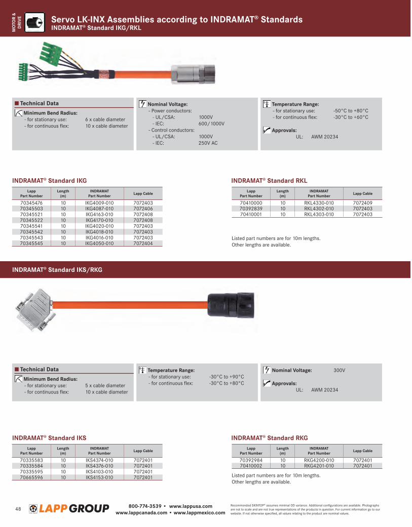
800-774-3539 • www.lappusa.comwww.lappcanada.com • www.lappmexico.com
48Recommended SKINTOP® assumes minimal OD variance. Additional configurations are available. Photographs are not to scale and are not true representations of the products in question. For current information go to our website. If not otherwise specified, all values relating to the product are nominal values.
MO
TOR
& D
RIV
E Servo LK-INX Assemblies according to INDRAMAT® StandardsINDRAMAT® Standard IKG/RKL
Minimum Bend Radius: - for stationary use: 6 x cable diameter - for continuous flex: 10 x cable diameter
Minimum Bend Radius: - for stationary use: 5 x cable diameter - for continuous flex: 10 x cable diameter
Nominal Voltage: - Power conductors: - UL/CSA: 1000V - IEC: 600/1000V - Control conductors: - UL/CSA: 1000V - IEC: 250V AC
Temperature Range: - for stationary use: -30°C to +90°C - for continuous flex: -30°C to +80°C
Temperature Range: - for stationary use: -50°C to +80°C - for continuous flex: -30°C to +60°C
Approvals: UL: AWM 20234
Nominal Voltage: 300V
Approvals: UL: AWM 20234
INDRAMAT® Standard IKG
INDRAMAT® Standard IKS
INDRAMAT® Standard RKL
INDRAMAT® Standard RKG
Lapp Part Number
Length(m)
INDRAMAT Part Number Lapp Cable
70345476 10 IKG4009-010 707240370345503 10 IKG4087-010 707240670345521 10 IKG4163-010 707240870345522 10 IKG4170-010 707240870345541 10 IKG4020-010 707240370345542 10 IKG4018-010 707240370345543 10 IKG4016-010 707240370345545 10 IKG4050-010 7072404
Lapp Part Number
Length(m)
INDRAMAT Part Number Lapp Cable
70335583 10 IKS4374-010 707240170335584 10 IKS4376-010 707240170335595 10 IKS4103-010 707240170665596 10 IKS4153-010 7072401
Lapp Part Number
Length(m)
INDRAMAT Part Number Lapp Cable
70410000 10 RKL4330-010 707240970392839 10 RKL4302-010 707240370410001 10 RKL4303-010 7072403
Lapp Part Number
Length(m)
INDRAMAT Part Number Lapp Cable
70392984 10 RKG4200-010 707240170410002 10 RKG4201-010 7072401
Listed part numbers are for 10m lengths. Other lengths are available.
Listed part numbers are for 10m lengths. Other lengths are available.
Technical Data
Technical Data
INDRAMAT® Standard IKS/RKG
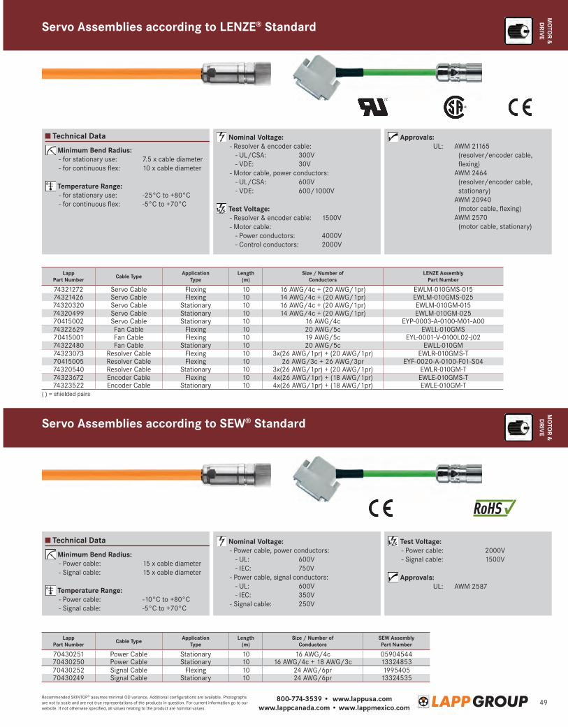
800-774-3539 • www.lappusa.comwww.lappcanada.com • www.lappmexico.com
49Recommended SKINTOP® assumes minimal OD variance. Additional configurations are available. Photographs are not to scale and are not true representations of the products in question. For current information go to our website. If not otherwise specified, all values relating to the product are nominal values.
MO
TOR &
DRIV
E
Technical Data
Technical Data
Minimum Bend Radius: - for stationary use: 7.5 x cable diameter - for continuous flex: 10 x cable diameter
Temperature Range: - for stationary use: -25°C to +80°C - for continuous flex: -5°C to +70°C
Minimum Bend Radius: - Power cable: 15 x cable diameter - Signal cable: 15 x cable diameter
Temperature Range: - Power cable: -10°C to +80°C - Signal cable: -5°C to +70°C
Nominal Voltage: - Resolver & encoder cable: - UL/CSA: 300V - VDE: 30V - Motor cable, power conductors: - UL/CSA: 600V - VDE: 600/1000V
Test Voltage: - Resolver & encoder cable: 1500V - Motor cable: - Power conductors: 4000V - Control conductors: 2000V
Nominal Voltage: - Power cable, power conductors: - UL: 600V - IEC: 750V - Power cable, signal conductors: - UL: 600V - IEC: 350V - Signal cable: 250V
Approvals: UL: A WM 21165
(resolver/encoder cable, flexing)
A WM 2464 (resolver/encoder cable, stationary)
A WM 20940 (motor cable, flexing)
A WM 2570 (motor cable, stationary)
Test Voltage: - Power cable: 2000V - Signal cable: 1500V
Approvals: UL: AWM 2587
Servo Assemblies according to LENZE® Standard
Lapp Part Number Cable Type Application
TypeLength
(m)Size / Number of
ConductorsLENZE Assembly
Part Number
74321272 Servo Cable Flexing 10 16 AWG/4c + (20 AWG/1pr) EWLM-010GMS-01574321426 Servo Cable Flexing 10 14 AWG/4c + (20 AWG/1pr) EWLM-010GMS-02574320320 Servo Cable Stationary 10 16 AWG/4c + (20 AWG/1pr) EWLM-010GM-01574320499 Servo Cable Stationary 10 14 AWG/4c + (20 AWG/1pr) EWLM-010GM-02570415002 Servo Cable Stationary 10 16 AWG/4c EYP-0003-A-0100-M01-A0074322629 Fan Cable Flexing 10 20 AWG/5c EWLL-010GMS70415001 Fan Cable Flexing 10 19 AWG/5c EYL-0001-V-0100L02-J0274322480 Fan Cable Stationary 10 20 AWG/5c EWLL-010GM74323073 Resolver Cable Flexing 10 3x(26 AWG/1pr) + (20 AWG/1pr) EWLR-010GMS-T70415005 Resolver Cable Flexing 10 26 AWG/3c + 26 AWG/3pr EYF-0020-A-0100-F01-S0474320540 Resolver Cable Stationary 10 3x(26 AWG/1pr) + (20 AWG/1pr) EWLR-010GM-T74323672 Encoder Cable Flexing 10 4x(26 AWG/1pr) + (18 AWG/1pr) EWLE-010GMS-T74323522 Encoder Cable Stationary 10 4x(26 AWG/1pr) + (18 AWG/1pr) EWLE-010GM-T
Lapp Part Number Cable Type Application
TypeLength
(m)Size / Number of
ConductorsSEW AssemblyPart Number
70430251 Power Cable Stationary 10 16 AWG/4c 0590454470430250 Power Cable Stationary 10 16 AWG/4c + 18 AWG/3c 1332485370430252 Signal Cable Flexing 10 24 AWG/6pr 199540570430249 Signal Cable Stationary 10 24 AWG/6pr 13324535
( ) = shielded pairs
Servo Assemblies according to SEW® Standard
MO
TOR &
DRIV
E
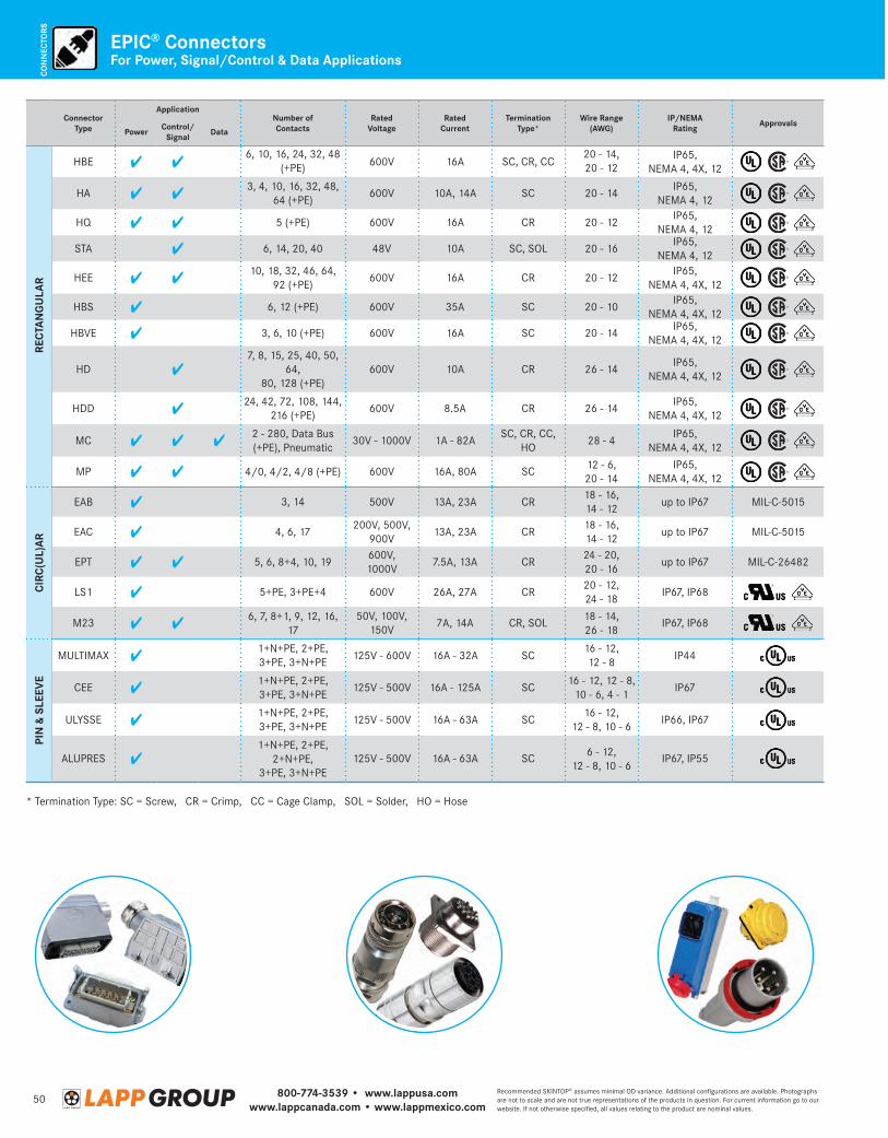
800-774-3539 • www.lappusa.comwww.lappcanada.com • www.lappmexico.com
50Recommended SKINTOP® assumes minimal OD variance. Additional configurations are available. Photographs are not to scale and are not true representations of the products in question. For current information go to our website. If not otherwise specified, all values relating to the product are nominal values.
CON
NEC
TORS
For Power, Signal/Control & Data ApplicationsEPIC® Connectors
Connector Type
ApplicationNumber ofContacts
RatedVoltage
RatedCurrent
TerminationType*
Wire Range(AWG)
IP/NEMARating Approvals
Power Control/Signal Data
RECT
AN
GU
LAR
HBE6, 10, 16, 24, 32, 48
(+PE) 600V 16A SC, CR, CC20 - 14, 20 - 12
IP65, NEMA 4, 4X, 12
HA3, 4, 10, 16, 32, 48,
64 (+PE)600V 10A, 14A SC 20 - 14
IP65, NEMA 4, 12
HQ 5 (+PE) 600V 16A CR 20 - 12IP65,
NEMA 4, 12
STA 6, 14, 20, 40 48V 10A SC, SOL 20 - 16IP65,
NEMA 4, 12
HEE10, 18, 32, 46, 64,
92 (+PE)600V 16A CR 20 - 12
IP65, NEMA 4, 4X, 12
HBS 6, 12 (+PE) 600V 35A SC 20 - 10IP65,
NEMA 4, 4X, 12
HBVE 3, 6, 10 (+PE) 600V 16A SC 20 - 14IP65,
NEMA 4, 4X, 12
HD7, 8, 15, 25, 40, 50,
64,80, 128 (+PE)
600V 10A CR 26 - 14IP65,
NEMA 4, 4X, 12
HDD24, 42, 72, 108, 144,
216 (+PE)600V 8.5A CR 26 - 14
IP65, NEMA 4, 4X, 12
MC2 - 280, Data Bus (+PE), Pneumatic
30V - 1000V 1A - 82ASC, CR, CC,
HO28 - 4
IP65, NEMA 4, 4X, 12
MP 4/0, 4/2, 4/8 (+PE) 600V 16A, 80A SC12 - 6, 20 - 14
IP65, NEMA 4, 4X, 12
CIRC
(UL)
AR
EAB 3, 14 500V 13A, 23A CR18 - 16, 14 - 12
up to IP67 MIL-C-5015
EAC 4, 6, 17200V, 500V,
900V13A, 23A CR
18 - 16, 14 - 12
up to IP67 MIL-C-5015
EPT 5, 6, 8+4, 10, 19600V, 1000V
7.5A, 13A CR24 - 20, 20 - 16
up to IP67 MIL-C-26482
LS1 5+PE, 3+PE+4 600V 26A, 27A CR20 - 12, 24 - 18
IP67, IP68
M236, 7, 8+1, 9, 12, 16,
1750V, 100V,
150V7A, 14A CR, SOL
18 - 14, 26 - 18
IP67, IP68
PIN
& S
LEEV
E
MULTIMAX1+N+PE, 2+PE, 3+PE, 3+N+PE
125V - 600V 16A - 32A SC16 - 12, 12 - 8
IP44
CEE1+N+PE, 2+PE,3+PE, 3+N+PE
125V - 500V 16A - 125A SC16 - 12, 12 - 8,
10 - 6, 4 - 1IP67
ULYSSE1+N+PE, 2+PE,3+PE, 3+N+PE
125V - 500V 16A - 63A SC16 - 12,
12 - 8, 10 - 6IP66, IP67
ALUPRES1+N+PE, 2+PE,
2+N+PE,3+PE, 3+N+PE
125V - 500V 16A - 63A SC 6 - 12, 12 - 8, 10 - 6
IP67, IP55
* Termination Type: SC = Screw, CR = Crimp, CC = Cage Clamp, SOL = Solder, HO = Hose
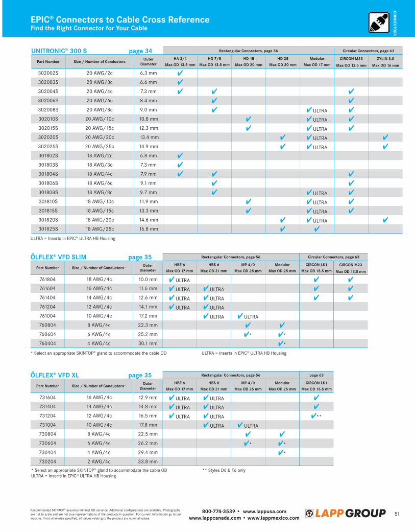
800-774-3539 • www.lappusa.comwww.lappcanada.com • www.lappmexico.com
51Recommended SKINTOP® assumes minimal OD variance. Additional configurations are available. Photographs are not to scale and are not true representations of the products in question. For current information go to our website. If not otherwise specified, all values relating to the product are nominal values.
CON
NECTO
RS
Find the Right Connector for Your CableEPIC® Connectors to Cable Cross Reference
UNITRONIC® 300 S page 34 Rectangular Connectors, page 56 Circular Connectors, page 63
Part Number Size / Number of Conductors OuterDiameter
HA 3/4 HD 7/8 HD 15 HD 25 Modular CIRCON M23 ZYLIN 3.0Max OD 13.5 mm Max OD 13.5 mm Max OD 20 mm Max OD 20 mm Max OD 17 mm Max OD 13.5 mm Max OD 16 mm
302002S 20 AWG/2c 6.3 mm
302003S 20 AWG/3c 6.6 mm
302004S 20 AWG/4c 7.3 mm
302006S 20 AWG/6c 8.4 mm
302008S 20 AWG/8c 9.0 mm ULTRA
302010S 20 AWG/10c 10.8 mm ULTRA
302015S 20 AWG/15c 12.3 mm ULTRA
302020S 20 AWG/20c 13.4 mm ULTRA
302025S 20 AWG/25c 14.9 mm ULTRA
301802S 18 AWG/2c 6.8 mm
301803S 18 AWG/3c 7.3 mm
301804S 18 AWG/4c 7.9 mm
301806S 18 AWG/6c 9.1 mm
301808S 18 AWG/8c 9.7 mm ULTRA
301810S 18 AWG/10c 11.9 mm ULTRA
301815S 18 AWG/15c 13.3 mm ULTRA
301820S 18 AWG/20c 14.6 mm ULTRA
301825S 18 AWG/25c 16.8 mm
* Select an appropriate SKINTOP® gland to accommodate the cable OD ULTRA = Inserts in EPIC® ULTRA HB Housing
ULTRA = Inserts in EPIC® ULTRA HB Housing
* Select an appropriate SKINTOP® gland to accommodate the cable OD ** Styles D6 & F6 onlyULTRA = Inserts in EPIC® ULTRA HB Housing
ÖLFLEX® VFD SLIM page 35 Rectangular Connectors, page 56 Circular Connectors, page 63
Part Number Size / Number of Conductors* OuterDiameter
HBE 6 HBS 6 MP 4/0 Modular CIRCON LS1 CIRCON M23Max OD 17 mm Max OD 21 mm Max OD 25 mm Max OD 25 mm Max OD 15.5 mm Max OD 13.5 mm
761804 18 AWG/4c 10.0 mm ULTRA
761604 16 AWG/4c 11.6 mm ULTRA ULTRA
761404 14 AWG/4c 12.6 mm ULTRA ULTRA
761204 12 AWG/4c 14.1 mm ULTRA ULTRA
761004 10 AWG/4c 17.2 mm ULTRA ULTRA
760804 8 AWG/4c 22.3 mm
760604 6 AWG/4c 25.2 mm * *
760404 4 AWG/4c 30.1 mm *
ÖLFLEX® VFD XL page 35 Rectangular Connectors, page 56 page 63
Part Number Size / Number of Conductors* OuterDiameter
HBE 6 HBS 6 MP 4/0 Modular CIRCON LS1
Max OD 17 mm Max OD 21 mm Max OD 25 mm Max OD 25 mm Max OD 15.5 mm
731604 16 AWG/4c 12.9 mm ULTRA ULTRA
731404 14 AWG/4c 14.8 mm ULTRA ULTRA
731204 12 AWG/4c 16.5 mm ULTRA ULTRA **
731004 10 AWG/4c 17.8 mm ULTRA ULTRA
730804 8 AWG/4c 22.5 mm
730604 6 AWG/4c 26.2 mm * *
730404 4 AWG/4c 29.4 mm *
730204 2 AWG/4c 33.8 mm
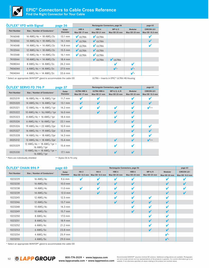
800-774-3539 • www.lappusa.comwww.lappcanada.com • www.lappmexico.com
52Recommended SKINTOP® assumes minimal OD variance. Additional configurations are available. Photographs are not to scale and are not true representations of the products in question. For current information go to our website. If not otherwise specified, all values relating to the product are nominal values.
CON
NEC
TORS
Find the Right Connector for Your CableEPIC® Connectors to Cable Cross Reference
ÖLFLEX® CHAIN 896 P page 40 Rectangular Connectors, page 56 page 63
Part Number Size / Number of Conductors* OuterDiameter
HA 3 HA 4 HBE 6 HBS 6 MP 4/0 Modular CIRCON LS1Max OD 13.5 mm Max OD 13.5 mm Max OD 25 mm Max OD 25 mm Max OD 25 mm Max OD 25 mm Max OD 15.5 mm
1023229 16 AWG/4c 9.6 mm
1023230 16 AWG/5c 10.0 mm
1023238 14 AWG/4c 11.0 mm
1023239 14 AWG/5c 12.0 mm
1023245 12 AWG/4c 12.5 mm
1023246 12 AWG/5c 13.7 mm
1023248 10 AWG/4c 14.3 mm
1023249 10 AWG/5c 15.7 mm
1023250 8 AWG/4c 17.0 mm
1023251 8 AWG/5c 18.9 mm
1023252 6 AWG/4c 21.2 mm
1023253 6 AWG/5c 23.8 mm
1023254 4 AWG/4c 25.9 mm *
1023255 4 AWG/5c 29.0 mm *
* Select an appropriate SKINTOP® gland to accommodate the cable OD
* Select an appropriate SKINTOP® gland to accommodate the cable OD ULTRA = Inserts in EPIC® ULTRA HB Housing
ÖLFLEX® SERVO FD 796 P page 37 Rectangular Connectors, page 56 page 63
Part Number Size / Number of Conductors* OuterDiameter
ULTRA HBE 6 ULTRA HBS 6 MP 4/2, 4/8 Modular CIRCON LS1
Max OD 17 mm Max OD 21 mm Max OD 25 mm Max OD 25 mm Max OD 15.5 mm
0025319 16 AWG/4c + 16 AWG/1pr 11.7 mm
0025320 14 AWG/4c + 16 AWG/1pr 13.1 mm
0025321 12 AWG/4c + 16 AWG/1pr 14.2 mm **
0025322 10 AWG/4c + 16/AWG/1pr 16.0 mm
0025323 8 AWG/4c + 16 AWG/1pr 18.4 mm
0025324 6 AWG/4c + 16 AWG/1pr 22.1 mm
0025326 19 AWG/4c + 22 AWG/2pr 10.9 mm
0025327 16 AWG/4c + 19 AWG/2pr 12.3 mm
0025328 14 AWG/4c + 18 AWG/2pr 14.3 mm
0025312 12 AWG/4c + 18 AWG/2pr 15.4 mm **
002532912 AWG/4c + 18 AWG/1pr +
16 AWG/1pr15.6 mm
002533010 AWG/4c + 18 AWG/1pr +
16 AWG/1pr17.1 mm
* Pairs are individually shielded ** Styles D6 & F6 only
ÖLFLEX® VFD with Signal page 36 Rectangular Connectors, page 56 page 63
Part Number Size / Number of Conductors* OuterDiameter
HBE 6 HBS 6 MP 4/2 Modular CIRCON LS1
Max OD 17 mm Max OD 21 mm Max OD 25 mm Max OD 25 mm Max OD 15.5 mm
7416048 16 AWG/4c + 18 AWG/2c 13.1 mm ULTRA ULTRA7414044 14 AWG/4c + 18 AWG/2c 14.1 mm ULTRA ULTRA
7414048 14 AWG/4c + 14 AWG/2c 14.8 mm ULTRA ULTRA
7412044 12 AWG/4c + 18 AWG/2c 15.5 mm ULTRA ULTRA
7412048 12 AWG/4c + 14 AWG/2c 16.1 mm ULTRA ULTRA
7410044 10 AWG/4c + 14 AWG/2c 18.4 mm ULTRA ULTRA
7408044 8 AWG/4c + 14 AWG/2c 24.2 mm
7406044 6 AWG/4c + 14 AWG/2c 27.5 mm * *
7404044 4 AWG/4c + 14 AWG/2c 33.6 mm *
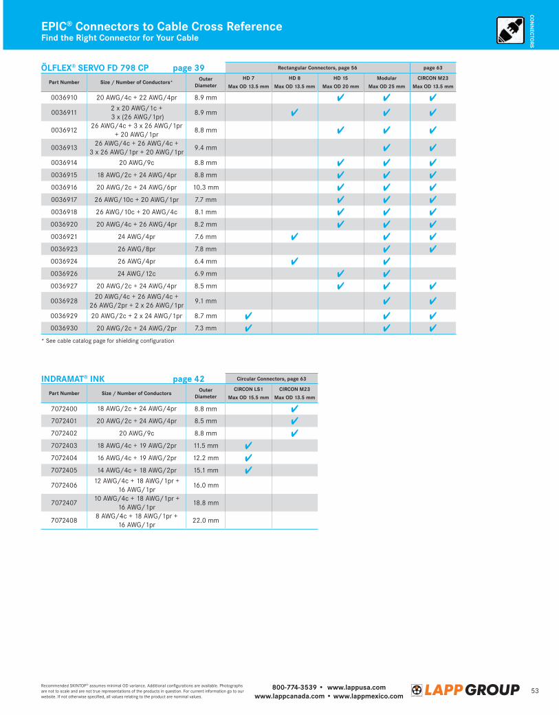
800-774-3539 • www.lappusa.comwww.lappcanada.com • www.lappmexico.com
53Recommended SKINTOP® assumes minimal OD variance. Additional configurations are available. Photographs are not to scale and are not true representations of the products in question. For current information go to our website. If not otherwise specified, all values relating to the product are nominal values.
CON
NECTO
RS
Find the Right Connector for Your CableEPIC® Connectors to Cable Cross Reference
ÖLFLEX® SERVO FD 798 CP page 39 Rectangular Connectors, page 56 page 63
Part Number Size / Number of Conductors* OuterDiameter
HD 7 HD 8 HD 15 Modular CIRCON M23
Max OD 13.5 mm Max OD 13.5 mm Max OD 20 mm Max OD 25 mm Max OD 13.5 mm
0036910 20 AWG/4c + 22 AWG/4pr 8.9 mm
00369112 x 20 AWG/1c + 3 x (26 AWG/1pr)
8.9 mm
003691226 AWG/4c + 3 x 26 AWG/1pr
+ 20 AWG/1pr8.8 mm
003691326 AWG/4c + 26 AWG/4c +
3 x 26 AWG/1pr + 20 AWG/1pr9.4 mm
0036914 20 AWG/9c 8.8 mm
0036915 18 AWG/2c + 24 AWG/4pr 8.8 mm
0036916 20 AWG/2c + 24 AWG/6pr 10.3 mm
0036917 26 AWG/10c + 20 AWG/1pr 7.7 mm
0036918 26 AWG/10c + 20 AWG/4c 8.1 mm
0036920 20 AWG/4c + 26 AWG/4pr 8.2 mm
0036921 24 AWG/4pr 7.6 mm
0036923 26 AWG/8pr 7.8 mm
0036924 26 AWG/4pr 6.4 mm
0036926 24 AWG/12c 6.9 mm
0036927 20 AWG/2c + 24 AWG/4pr 8.5 mm
003692820 AWG/4c + 26 AWG/4c +
26 AWG/2pr + 2 x 26 AWG/1pr9.1 mm
0036929 20 AWG/2c + 2 x 24 AWG/1pr 8.7 mm
0036930 20 AWG/2c + 24 AWG/2pr 7.3 mm
* See cable catalog page for shielding configuration
INDRAMAT® INK page 42 Circular Connectors, page 63
Part Number Size / Number of Conductors OuterDiameter
CIRCON LS1 CIRCON M23
Max OD 15.5 mm Max OD 13.5 mm
7072400 18 AWG/2c + 24 AWG/4pr 8.8 mm
7072401 20 AWG/2c + 24 AWG/4pr 8.5 mm
7072402 20 AWG/9c 8.8 mm
7072403 18 AWG/4c + 19 AWG/2pr 11.5 mm
7072404 16 AWG/4c + 19 AWG/2pr 12.2 mm
7072405 14 AWG/4c + 18 AWG/2pr 15.1 mm
707240612 AWG/4c + 18 AWG/1pr +
16 AWG/1pr16.0 mm
707240710 AWG/4c + 18 AWG/1pr +
16 AWG/1pr18.8 mm
70724088 AWG/4c + 18 AWG/1pr +
16 AWG/1pr22.0 mm
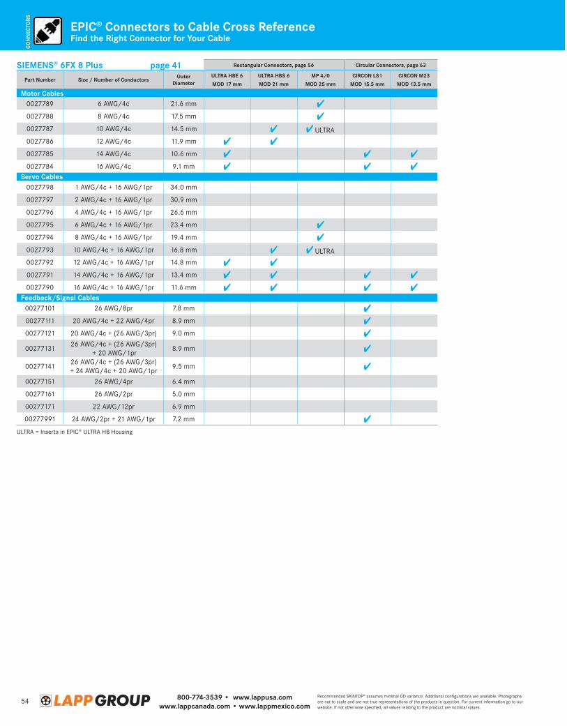
800-774-3539 • www.lappusa.comwww.lappcanada.com • www.lappmexico.com
54Recommended SKINTOP® assumes minimal OD variance. Additional configurations are available. Photographs are not to scale and are not true representations of the products in question. For current information go to our website. If not otherwise specified, all values relating to the product are nominal values.
CON
NEC
TORS
Find the Right Connector for Your CableEPIC® Connectors to Cable Cross Reference
SIEMENS® 6FX 8 Plus page 41 Rectangular Connectors, page 56 Circular Connectors, page 63
Part Number Size / Number of Conductors OuterDiameter
ULTRA HBE 6 ULTRA HBS 6 MP 4/0 CIRCON LS1 CIRCON M23
MOD 17 mm MOD 21 mm MOD 25 mm MOD 15.5 mm MOD 13.5 mm
Motor Cables0027789 6 AWG/4c 21.6 mm
0027788 8 AWG/4c 17.5 mm
0027787 10 AWG/4c 14.5 mm ULTRA
0027786 12 AWG/4c 11.9 mm
0027785 14 AWG/4c 10.6 mm
0027784 16 AWG/4c 9.1 mmServo Cables
0027798 1 AWG/4c + 16 AWG/1pr 34.0 mm
0027797 2 AWG/4c + 16 AWG/1pr 30.9 mm
0027796 4 AWG/4c + 16 AWG/1pr 26.6 mm
0027795 6 AWG/4c + 16 AWG/1pr 23.4 mm
0027794 8 AWG/4c + 16 AWG/1pr 19.4 mm
0027793 10 AWG/4c + 16 AWG/1pr 16.8 mm ULTRA
0027792 12 AWG/4c + 16 AWG/1pr 14.8 mm
0027791 14 AWG/4c + 16 AWG/1pr 13.4 mm
0027790 16 AWG/4c + 16 AWG/1pr 11.6 mmFeedback/Signal Cables
00277101 26 AWG/8pr 7.8 mm
00277111 20 AWG/4c + 22 AWG/4pr 8.9 mm
00277121 20 AWG/4c + (26 AWG/3pr) 9.0 mm
0027713126 AWG/4c + (26 AWG/3pr)
+ 20 AWG/1pr8.9 mm
0027714126 AWG/4c + (26 AWG/3pr) + 24 AWG/4c + 20 AWG/1pr
9.5 mm
00277151 26 AWG/4pr 6.4 mm
00277161 26 AWG/2pr 5.0 mm
00277171 22 AWG/12pr 6.9 mm
00277991 24 AWG/2pr + 21 AWG/1pr 7.2 mm
ULTRA = Inserts in EPIC® ULTRA HB Housing
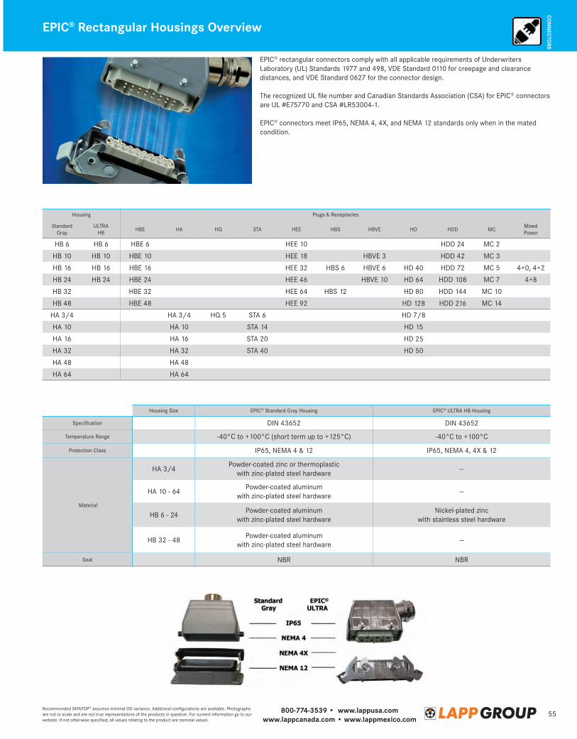
800-774-3539 • www.lappusa.comwww.lappcanada.com • www.lappmexico.com
55Recommended SKINTOP® assumes minimal OD variance. Additional configurations are available. Photographs are not to scale and are not true representations of the products in question. For current information go to our website. If not otherwise specified, all values relating to the product are nominal values.
CON
NECTO
RSEPIC® Rectangular Housings Overview
EPIC® rectangular connectors comply with all applicable requirements of Underwriters Laboratory (UL) Standards 1977 and 498, VDE Standard 0110 for creepage and clearance distances, and VDE Standard 0627 for the connector design.
The recognized UL file number and Canadian Standards Association (CSA) for EPIC® connectors are UL #E75770 and CSA #LR53004-1.
EPIC® connectors meet IP65, NEMA 4, 4X, and NEMA 12 standards only when in the mated condition.
Housing Plugs & Receptacles
Standard Gray
ULTRA HB
HBE HA HQ STA HEE HBS HBVE HD HDD MCMixed Power
HB 6 HB 6 HBE 6 HEE 10 HDD 24 MC 2
HB 10 HB 10 HBE 10 HEE 18 HBVE 3 HDD 42 MC 3
HB 16 HB 16 HBE 16 HEE 32 HBS 6 HBVE 6 HD 40 HDD 72 MC 5 4+0, 4+2
HB 24 HB 24 HBE 24 HEE 46 HBVE 10 HD 64 HDD 108 MC 7 4+8
HB 32 HBE 32 HEE 64 HBS 12 HD 80 HDD 144 MC 10
HB 48 HBE 48 HEE 92 HD 128 HDD 216 MC 14
HA 3/4 HA 3/4 HQ 5 STA 6 HD 7/8
HA 10 HA 10 STA 14 HD 15
HA 16 HA 16 STA 20 HD 25
HA 32 HA 32 STA 40 HD 50
HA 48 HA 48
HA 64 HA 64
Housing Size EPIC® Standard Gray Housing EPIC® ULTRA HB Housing
Specification DIN 43652 DIN 43652
Temperature Range -40°C to +100°C (short term up to +125°C) -40°C to +100°C
Protection Class IP65, NEMA 4 & 12 IP65, NEMA 4, 4X & 12
Material
HA 3/4Powder-coated zinc or thermoplastic
with zinc-plated steel hardware—
HA 10 - 64Powder-coated aluminum
with zinc-plated steel hardware—
HB 6 - 24Powder-coated aluminum
with zinc-plated steel hardwareNickel-plated zinc
with stainless steel hardware
HB 32 - 48Powder-coated aluminum
with zinc-plated steel hardware—
Seal NBR NBR
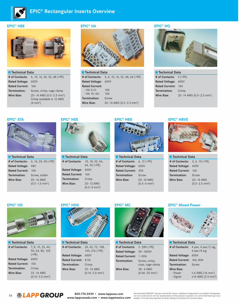
800-774-3539 • www.lappusa.comwww.lappcanada.com • www.lappmexico.com
56Recommended SKINTOP® assumes minimal OD variance. Additional configurations are available. Photographs are not to scale and are not true representations of the products in question. For current information go to our website. If not otherwise specified, all values relating to the product are nominal values.
CON
NEC
TORS
EPIC® Rectangular Inserts Overview
EPIC® HBE
Technical Data# of Contacts:Rated Voltage:Rated Current:Termination:Wire Size:
6, 10, 16, 24, 32, 48 (+PE)
600V
16A
Screw, crimp, cage clamp
20 - 14 AWG (0.5 - 2.5 mm2) Crimp available in 12 AWG (4 mm2)
EPIC® STA
Technical Data# of Contacts:Rated Voltage:Rated Current:Termination:Wire Size:
6, 14, 20, 40 (+PE)
48V
10A
Screw, solder
20 - 16 AWG (0.5 - 1.5 mm2)
EPIC® HD
Technical Data# of Contacts:
Rated Voltage:Rated Current:Termination:Wire Size:
7, 8, 15, 25, 40, 50, 64, 80, 128 (+PE)
600V
10A
Crimp
22 - 14 AWG (0.14 - 2.5 mm2)
EPIC® HA
# of Contacts:Rated Voltage:Rated Current: - HA 3/4: - HA 10 - 64:
Termination:Wire Size:
Technical Data3, 4, 10, 16, 32, 48, 64 (+PE)
600V
10A 14A
Screw
20 - 14 AWG (0.5 - 2.5 mm2)
EPIC® HEE
# of Contacts:
Rated Voltage:Rated Current:Termination:Wire Size:
Technical Data10, 18, 32, 46, 64, 92 (+PE)
600V
16A
Crimp
20 - 12 AWG (0.5 - 4 mm2)
EPIC® HDD
# of Contacts:
Rated Voltage:Rated Current:Termination:Wire Size:
Technical Data24, 42, 72, 108, 144, 216 (+PE)
600V
8.5A
Crimp
22 - 14 AWG (0.14 - 2.5 mm2)
EPIC® HQ
Technical Data# of Contacts:Rated Voltage:Rated Current:Termination:Wire Size:
5 (+PE)
600V
16A
Crimp
20 - 14 AWG (0.5 - 2.5 mm2)
EPIC® HBS
Technical Data# of Contacts:Rated Voltage:Rated Current:Termination:Wire Size:
6, 12 (+PE)
600V
35A
Screw
20 - 10 AWG (0.5 - 6 mm2)
EPIC® MC
Technical Data# of Contacts:Rated Voltage:Rated Current:Termination:
Wire Size:
2 - 280 (+PE)
30 - 1000V
1 - 82A
Screw, crimp, coax, cage clamp
28 - 4 AWG (0.06 - 25 mm2)
EPIC® HBVE
Technical Data# of Contacts:Rated Voltage:Rated Current:Termination:Wire Size:
3, 6, 10 (+PE)
600V
16A
Screw
20 - 14 AWG (0.5 - 2.5 mm2)
EPIC® Mixed Power
Technical Data# of Contacts:
Rated Voltage:Rated Current:Termination:Wire Size: - Power - Signal
4 pwr, 4 pwr/2 sig, 4 pwr/8 sig
600V
16A, 80A
Screw
≤ 6 AWG (16 mm2) ≤14 AWG (2.5 mm2)
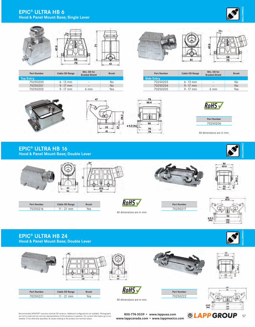
800-774-3539 • www.lappusa.comwww.lappcanada.com • www.lappmexico.com
57Recommended SKINTOP® assumes minimal OD variance. Additional configurations are available. Photographs are not to scale and are not true representations of the products in question. For current information go to our website. If not otherwise specified, all values relating to the product are nominal values.
CON
NECTO
RSEPIC® ULTRA HB 6Hood & Panel Mount Base; Single Lever
All dimensions are in mm.
All dimensions are in mm.
All dimensions are in mm.
Part Number Cable OD Range Min. OD for Braided Shield Brush
Top Entry70250200 6 - 13 mm — No70250201 9 - 17 mm — No70250202 9 - 17 mm 6 mm Yes
Part Number Cable OD Range Brush
70250216 11 - 21 mm Yes
Part Number Cable OD Range Brush
70250221 11 - 21 mm Yes
Part Number
70250206
Part Number
70250217
Part Number
70250222
Part Number Cable OD Range Min. OD for Braided Shield Brush
Side Entry70250203 6 - 13 mm — No70250204 9 - 17 mm — No70250205 9 - 17 mm 6 mm Yes
EPIC® ULTRA HB 16
EPIC® ULTRA HB 24
Hood & Panel Mount Base; Double Lever
Hood & Panel Mount Base; Double Lever
CON
NECTO
RSCO
NN
ECTORS
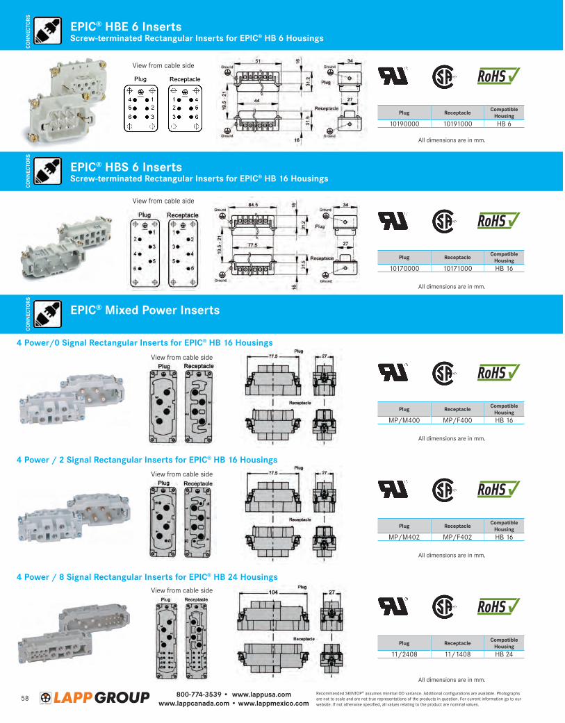
800-774-3539 • www.lappusa.comwww.lappcanada.com • www.lappmexico.com
58Recommended SKINTOP® assumes minimal OD variance. Additional configurations are available. Photographs are not to scale and are not true representations of the products in question. For current information go to our website. If not otherwise specified, all values relating to the product are nominal values.
CON
NEC
TORS
Screw-terminated Rectangular Inserts for EPIC® HB 6 HousingsEPIC® HBE 6 Inserts
All dimensions are in mm.
All dimensions are in mm.
All dimensions are in mm.
All dimensions are in mm.
All dimensions are in mm.
Plug Receptacle Compatible Housing
10190000 10191000 HB 6
Plug Receptacle Compatible Housing
10170000 10171000 HB 16
Plug Receptacle Compatible Housing
MP/M400 MP/F400 HB 16
Plug Receptacle Compatible Housing
MP/M402 MP/F402 HB 16
Plug Receptacle Compatible Housing
11/2408 11/1408 HB 24
4 Power / 2 Signal Rectangular Inserts for EPIC® HB 16 Housings
4 Power / 8 Signal Rectangular Inserts for EPIC® HB 24 Housings
View from cable side
View from cable side
View from cable side
View from cable side
View from cable side
EPIC® HBS 6 Inserts
EPIC® Mixed Power Inserts
Screw-terminated Rectangular Inserts for EPIC® HB 16 Housings
4 Power/0 Signal Rectangular Inserts for EPIC® HB 16 Housings
CON
NEC
TORS
CON
NEC
TORS
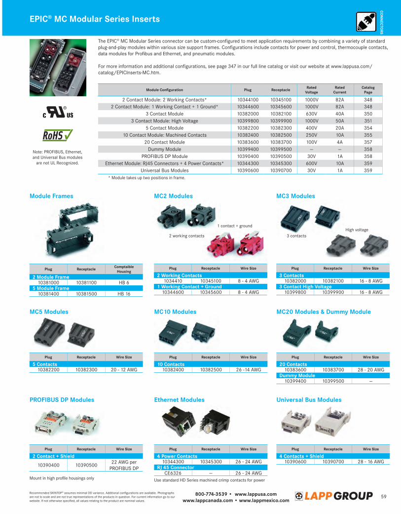
800-774-3539 • www.lappusa.comwww.lappcanada.com • www.lappmexico.com
59Recommended SKINTOP® assumes minimal OD variance. Additional configurations are available. Photographs are not to scale and are not true representations of the products in question. For current information go to our website. If not otherwise specified, all values relating to the product are nominal values.
CON
NECTO
RS
High voltage
EPIC® MC Modular Series Inserts
Module Configuration Plug Receptacle Rated Voltage
Rated Current
Catalog Page
2 Contact Module: 2 Working Contacts* 10344100 10345100 1000V 82A 3482 Contact Module: 1 Working Contact + 1 Ground* 10344600 10345600 1000V 82A 348
3 Contact Module 10382000 10382100 630V 40A 3503 Contact Module: High Voltage 10399800 10399900 1000V 50A 351
5 Contact Module 10382200 10382300 400V 20A 35410 Contact Module: Machined Contacts 10382400 10382500 250V 10A 355
20 Contact Module 10383600 10383700 100V 4A 357Dummy Module 10399400 10399500 — — 358
PROFIBUS DP Module 10390400 10390500 30V 1A 358Ethernet Module: RJ45 Connectors + 4 Power Contacts* 10344300 10345300 600V 10A 359
Universal Bus Modules 10390600 10390700 30V 1A 359
Plug Receptacle Wire Size
2 Working Contacts1034410 10345100 8 - 4 AWG
1 Working Contact + Ground10344600 10345600 8 - 4 AWG
Plug Receptacle Wire Size
3 Contacts10382000 10382100 16 - 8 AWG
3 Contact High Voltage10399800 10399900 16 - 8 AWG
Plug Receptacle Wire Size
20 Contacts10383600 10383700 28 - 20 AWG
Dummy Module10399400 10399500 —
Plug Receptacle Comptaible Housing
2 Module Frame10381000 10381100 HB 6
5 Module Frame10381400 10381500 HB 16
Plug Receptacle Wire Size
4 Contacts + Shield10390600 10390700 28 - 16 AWG
Plug Receptacle Wire Size
2 Contact + Shield
10390400 1039050022 AWG per
PROFIBUS DP
Plug Receptacle Wire Size
5 Contacts10382200 10382300 20 - 12 AWG
Plug Receptacle Wire Size
10 Contacts10382400 10382500 26 -14 AWG
Plug Receptacle Wire Size
4 Power Contacts10344300 10345300 26 - 24 AWG
RJ 45 ConnectorCE6326 — 26 - 24 AWG
2 working contacts
Mount in high profile housings only Use standard HD Series machined crimp contacts for power
* Module takes up two positions in frame.
3 contacts
MC2 Modules MC3 Modules
MC5 Modules MC10 Modules
Ethernet Modules
MC20 Modules & Dummy Module
Universal Bus ModulesPROFIBUS DP Modules
Module Frames
1 contact + ground
The EPIC® MC Modular Series connector can be custom-configured to meet application requirements by combining a variety of standard plug-and-play modules within various size support frames. Configurations include contacts for power and control, thermocouple contacts, data modules for Profibus and Ethernet, and pneumatic modules.
For more information and additional configurations, see page 347 in our full line catalog or visit our website at www.lappusa.com/catalog/EPICInserts-MC.htm.
Note: PROFIBUS, Ethernet, and Universal Bus modules
are not UL Recognized.
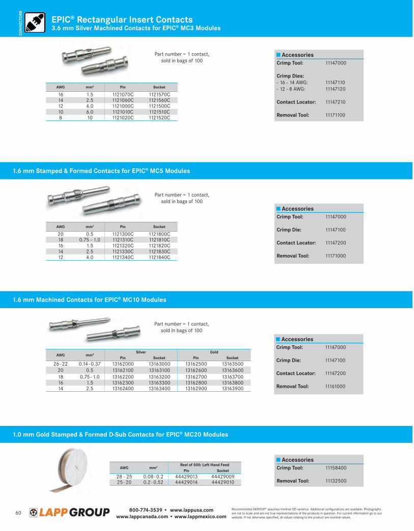
800-774-3539 • www.lappusa.comwww.lappcanada.com • www.lappmexico.com
60Recommended SKINTOP® assumes minimal OD variance. Additional configurations are available. Photographs are not to scale and are not true representations of the products in question. For current information go to our website. If not otherwise specified, all values relating to the product are nominal values.
CON
NEC
TORS
3.6 mm Silver Machined Contacts for EPIC® MC3 ModulesEPIC® Rectangular Insert Contacts
Part number = 1 contact, sold in bags of 100
Part number = 1 contact, sold in bags of 100
Part number = 1 contact, sold in bags of 100
AWG mm2Silver Gold
Pin Socket Pin Socket
26 - 22 0.14 - 0.37 13162000 13163000 13162500 1316350020 0.5 13162100 13163100 13162600 1316360018 0.75 - 1.0 13162200 13163200 13162700 1316370016 1.5 13162300 13163300 13162800 1316380014 2.5 13162400 13163400 13162900 13163900
Accessories
Accessories
Accessories
Accessories
Crimp Tool: 11147000
Crimp Die: 11147100
Contact Locator: 11147200
Removal Tool: 11161000
Crimp Tool: 11147000
Crimp Die: 11147100
Contact Locator: 11147200
Removal Tool: 11171000
Crimp Tool: 11158400
Removal Tool: 11132500
Crimp Tool: 11147000
Crimp Dies:- 16 - 14 AWG: 11147110- 12 - 8 AWG: 11147120
Contact Locator: 11147210
Removal Tool: 11171100
1.6 mm Stamped & Formed Contacts for EPIC® MC5 Modules
1.6 mm Machined Contacts for EPIC® MC10 Modules
1.0 mm Gold Stamped & Formed D-Sub Contacts for EPIC® MC20 Modules
AWG mm2 Pin Socket
16 1.5 1121070C 1121570C14 2.5 1121060C 1121560C12 4.0 1121000C 1121500C10 6.0 1121010C 1121510C8 10 1121020C 1121520C
AWG mm2Reel of 500: Left Hand Feed
Pin Socket
28 - 25 0.08 - 0.2 44429013 4442900925 - 20 0.2 - 0.52 44429014 44429010
AWG mm2 Pin Socket
20 0.5 1121300C 1121800C18 0.75 - 1.0 1121310C 1121810C16 1.5 1121320C 1121820C14 2.5 1121330C 1121830C12 4.0 1121340C 1121840C
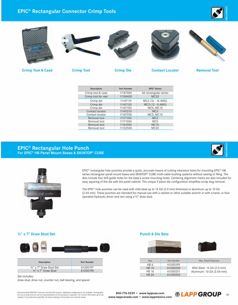
800-774-3539 • www.lappusa.comwww.lappcanada.com • www.lappmexico.com
61Recommended SKINTOP® assumes minimal OD variance. Additional configurations are available. Photographs are not to scale and are not true representations of the products in question. For current information go to our website. If not otherwise specified, all values relating to the product are nominal values.
CON
NECTO
RSEPIC® Rectangular Connector Crimp Tools
Description Part Number EPIC® Series
Crimp tool & case 11147000 All rectangular seriesCrimp tool for reel 11158400 MC20
Crimp die 11147110 MC3 (16 - 14 AWG)Crimp die 11147120 MC3 (12 - 8 AWG)Crimp die 11147100 MC5, MC10
Contact locator 11147210 MC3Contact locator 11147200 MC5, MC10
Removal tool 11171100 MC3Removal tool 11171000 MC5Removal tool 11161000 MC10Removal tool 11132500 MC20
Crimp Tool & Case Crimp Tool Crimp Die Contact Locator Removal Tool
EPIC® Rectangular Hole PunchFor EPIC® HB Panel Mount Bases & SKINTOP® CUBE
EPIC® rectangular hole punches provide a quick, accurate means of cutting clearance holes for mounting EPIC® HB series rectangular panel mount bases and SKINTOP® CUBE multi-cable bushing systems without sawing or filing. The dies include four drill guide holes for the base’s screw mounting holes. Centering alignment marks are also included for easy squaring of the die with the panel cabinet. The unique 2-piece die configuration simplifies scrap slug removal.
The EPIC® hole punches can be used with mild steel up to 14 GA (2.0 mm) thickness or aluminum up to 10 GA (2.54 mm). These punches are intended for manual use with a ratchet or other suitable wrench or with a hand- or foot-operated hydraulic driver and ram using a ¾” draw stud.
¾” x 7” Draw Stud Set Punch & Die Sets
Set includes: draw stud, drive nut, counter nut, ball bearing, and spacer
Size Part Number Max. Panel Thickness
HB 6 61U00199Mild Steel: 14 GA (2.0 mm)
Aluminum: 10 GA (2.54 mm)HB 10 61U00200HB 16 61U00201HB 24 61U00203
Description Part Number
¾” x 7” Draw Stud Set 61U00197¾” x 7” Draw Stud 61U00198
CON
NECTO
RS
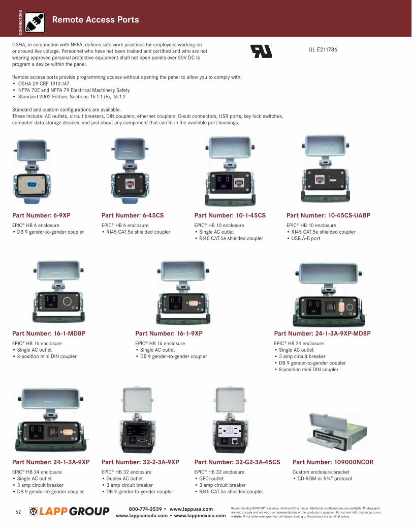
800-774-3539 • www.lappusa.comwww.lappcanada.com • www.lappmexico.com
62Recommended SKINTOP® assumes minimal OD variance. Additional configurations are available. Photographs are not to scale and are not true representations of the products in question. For current information go to our website. If not otherwise specified, all values relating to the product are nominal values.
CON
NEC
TORS
OSHA, in conjunction with NFPA, defines safe work practices for employees working on or around live voltage. Personnel who have not been trained and certified and who are not wearing approved personal protective equipment shall not open panels over 50V DC to program a device within the panel.
Remote access ports provide programming access without opening the panel to allow you to comply with:• OSHA 29 CRF 1910.147• NFPA 70E and NFPA 79 Electrical Machinery Safety • Standard 2002 Edition, Sections 16.1.1 (6), 16.1.2
Standard and custom configurations are available. These include: AC outlets, circuit breakers, DIN couplers, ethernet couplers, D-sub connectors, USB ports, key lock switches, computer data storage devices, and just about any component that can fit in the available port housings.
Remote Access Ports
UL E211786
Part Number: 6-9XPEPIC® HB 6 enclosure • DB 9 gender-to-gender coupler
Part Number: 6-45CSEPIC® HB 6 enclosure • RJ45 CAT.5e shielded coupler
Part Number: 10-1-45CSEPIC® HB 10 enclosure • Single AC outlet • RJ45 CAT.5e shielded coupler
Part Number: 16-1-9XPEPIC® HB 16 enclosure • Single AC outlet• DB 9 gender-to-gender coupler
Part Number: 16-1-MD8PEPIC® HB 16 enclosure • Single AC outlet• 8-position mini DIN coupler
Part Number: 10-45CS-UABPEPIC® HB 10 enclosure • RJ45 CAT.5e shielded coupler • USB A-B port
Part Number: 24-1-3A-9XPEPIC® HB 24 enclosure • Single AC outlet• 3 amp circuit breaker• DB 9 gender-to-gender coupler
Part Number: 24-1-3A-9XP-MD8PEPIC® HB 24 enclosure • Single AC outlet• 3 amp circuit breaker• DB 9 gender-to-gender coupler• 8-position mini DIN coupler
Part Number: 109000NCDRCustom enclosure bracket • CD-ROM or 5¼” protocol
Part Number: 32-2-3A-9XPEPIC® HB 32 enclosure • Duplex AC outlet • 3 amp circuit breaker • DB 9 gender-to-gender coupler
Part Number: 32-G2-3A-45CSEPIC® HB 32 enclosure • GFCI outlet • 3 amp circuit breaker • RJ45 CAT.5e shielded coupler
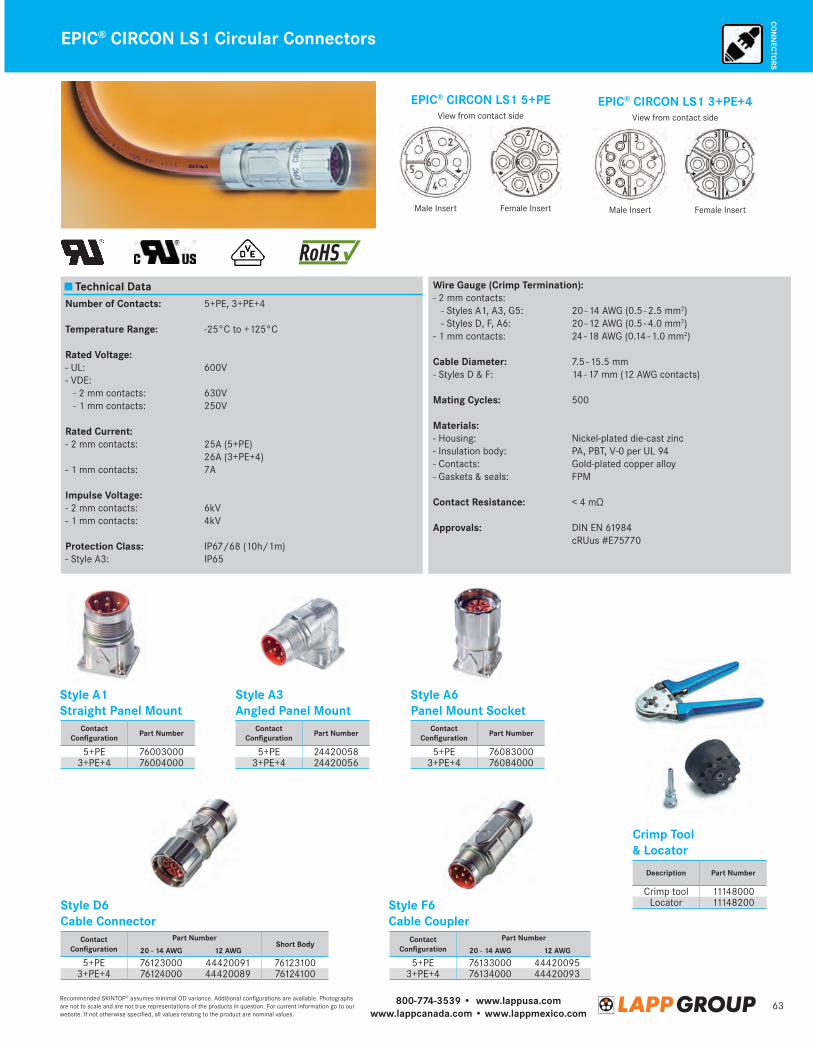
800-774-3539 • www.lappusa.comwww.lappcanada.com • www.lappmexico.com
63Recommended SKINTOP® assumes minimal OD variance. Additional configurations are available. Photographs are not to scale and are not true representations of the products in question. For current information go to our website. If not otherwise specified, all values relating to the product are nominal values.
CON
NECTO
RSEPIC® CIRCON LS1 Circular Connectors
Style A1 Straight Panel Mount
Style F6Cable Coupler
Style A3Angled Panel Mount
Style A6Panel Mount Socket
Crimp Tool& Locator
Style D6Cable Connector
Technical DataNumber of Contacts: 5+PE, 3+PE+4
Temperature Range: -25°C to +125°C
Rated Voltage: - UL: 600V- VDE: - 2 mm contacts: 630V - 1 mm contacts: 250V
Rated Current:- 2 mm contacts: 25A (5+PE) 26A (3+PE+4)- 1 mm contacts: 7A
Impulse Voltage:- 2 mm contacts: 6kV- 1 mm contacts: 4kV
Protection Class: IP67/68 (10h/1m)- Style A3: IP65
Wire Gauge (Crimp Termination):- 2 mm contacts: - Styles A1, A3, G5: 20 - 14 AWG (0.5 - 2.5 mm2) - Styles D, F, A6: 20 - 12 AWG (0.5 - 4.0 mm2)- 1 mm contacts: 24 - 18 AWG (0.14 - 1.0 mm2)
Cable Diameter: 7.5 - 15.5 mm- Styles D & F: 14 - 17 mm (12 AWG contacts)
Mating Cycles: 500
Materials:- Housing: Nickel-plated die-cast zinc- Insulation body: PA, PBT, V-0 per UL 94- Contacts: Gold-plated copper alloy- Gaskets & seals: FPM
Contact Resistance: < 4 mΩ
Approvals: DIN EN 61984 cRUus #E75770
EPIC® CIRCON LS1 5+PE
Male Insert Female Insert
View from contact sideEPIC® CIRCON LS1 3+PE+4
Male Insert Female Insert
View from contact side
Contact Configuration Part Number
5+PE 760030003+PE+4 76004000
Contact Configuration Part Number
5+PE 244200583+PE+4 24420056
Contact Configuration Part Number
5+PE 760830003+PE+4 76084000
Description Part Number
Crimp tool 11148000Locator 11148200
Contact Configuration
Part NumberShort Body
20 - 14 AWG 12 AWG
5+PE 76123000 44420091 761231003+PE+4 76124000 44420089 76124100
Contact Configuration
Part Number
20 - 14 AWG 12 AWG
5+PE 76133000 444200953+PE+4 76134000 44420093
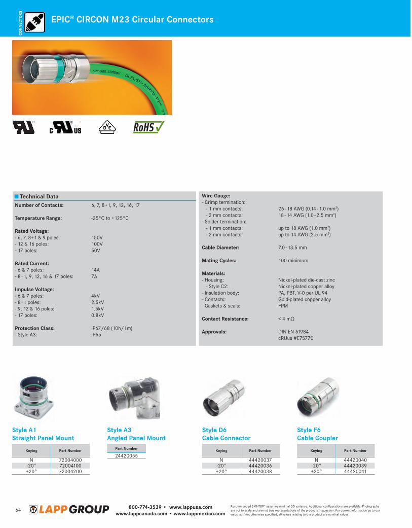
800-774-3539 • www.lappusa.comwww.lappcanada.com • www.lappmexico.com
64Recommended SKINTOP® assumes minimal OD variance. Additional configurations are available. Photographs are not to scale and are not true representations of the products in question. For current information go to our website. If not otherwise specified, all values relating to the product are nominal values.
CON
NEC
TORS
EPIC® CIRCON M23 Circular Connectors
Technical DataNumber of Contacts: 6, 7, 8+1, 9, 12, 16, 17
Temperature Range: -25°C to +125°C
Rated Voltage: - 6, 7, 8+1 & 9 poles: 150V- 12 & 16 poles: 100V- 17 poles: 50V
Rated Current:- 6 & 7 poles: 14A- 8+1, 9, 12, 16 & 17 poles: 7A
Impulse Voltage:- 6 & 7 poles: 4kV- 8+1 poles: 2.5kV- 9, 12 & 16 poles: 1.5kV- 17 poles: 0.8kV
Protection Class: IP67/68 (10h/1m)- Style A3: IP65
Wire Gauge:- Crimp termination: - 1 mm contacts: 26 - 18 AWG (0.14 - 1.0 mm2) - 2 mm contacts: 18 - 14 AWG (1.0 - 2.5 mm2)- Solder termination: - 1 mm contacts: up to 18 AWG (1.0 mm2) - 2 mm contacts: up to 14 AWG (2.5 mm2)
Cable Diameter: 7.0 - 13.5 mm
Mating Cycles: 100 minimum
Materials:- Housing: Nickel-plated die-cast zinc - Style C2: Nickel-plated copper alloy- Insulation body: PA, PBT, V-0 per UL 94- Contacts: Gold-plated copper alloy- Gaskets & seals: FPM
Contact Resistance: < 4 mΩ
Approvals: DIN EN 61984 cRUus #E75770
Style A1 Straight Panel Mount
Style A3Angled Panel Mount
Style D6Cable Connector
Style F6Cable Coupler
Part Number
24420055Keying Part Number
N 72004000-20° 72004100+20° 72004200
Keying Part Number
N 44420037-20° 44420036+20° 44420038
Keying Part Number
N 44420040-20° 44420039+20° 44420041
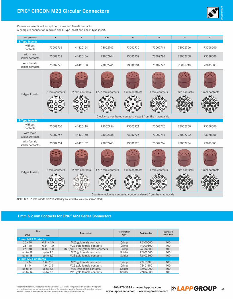
800-774-3539 • www.lappusa.comwww.lappcanada.com • www.lappmexico.com
65Recommended SKINTOP® assumes minimal OD variance. Additional configurations are available. Photographs are not to scale and are not true representations of the products in question. For current information go to our website. If not otherwise specified, all values relating to the product are nominal values.
CON
NECTO
RSEPIC® CIRCON M23 Circular Connectors
# of contacts 6 7 8+1 9 12 16 17
E-Type Insertswithout contacts 73002766 44420154 73002742 73002730 73002718 73002706 73008500
with malesolder contacts 73002768 44420156 73002744 73002732 73002720 73002708 73028500
with femalesolder contacts 73002770 44420158 73002746 73002734 73002722 73002710 73018500
E-Type Inserts2 mm contacts 2 mm contacts 1 & 2 mm contacts 1 mm contacts 1 mm contacts 1 mm contacts 1 mm contacts
Clockwise numbered contacts viewed from the mating sideP-Type Inserts
withoutcontacts
73002760 44420148 73002736 73002724 73002712 73002700 73008000
with male solder contacts
73002762 44420150 73002738 73002726 73002714 73002702 73028000
with female solder contacts
73002764 44420152 73002740 73002728 73002716 73002704 73018000
P-Type Inserts2 mm contacts 2 mm contacts 1 & 2 mm contacts 1 mm contacts 1 mm contacts 1 mm contacts 1 mm contacts
Counter-clockwise numbered contacts viewed from the mating side
Connector inserts will accept both male and female contacts. A complete connection requires one E-Type insert and one P-Type insert.
Note: 12 & 17 pole inserts for PCB soldering are available on request (non-stock)
SizeDescription Termination
Type Part Number Standard Pack SizeAWG mm2
1 mm M23 Contacts26 - 18 0.14 - 1.0 M23 gold male contacts Crimp 72400000 10026 - 18 0.14 - 1.0 M23 gold female contacts Crimp 74200600 10026 - 18 0.14 - 1.0 M23/LS1 HYP gold female contacts Crimp 74034500 100up to 18 up to 1.0 M23 gold male contacts Solder 72402000 100up to 18 up to 1.0 M23 gold female contacts Solder 72402600 100
2 mm M23 Contacts18 - 14 1.0 - 2.5 M23 gold male contacts Crimp 72401000 10018 - 14 1.0 - 2.5 M23 gold female contacts Crimp 72401600 100
up to 14 up to 2.5 M23 gold male contacts Solder 72403000 100up to 14 up to 2.5 M23 gold female contacts Solder 72404000 100
1 mm & 2 mm Contacts for EPIC® M23 Series Connectors

800-774-3539 • www.lappusa.comwww.lappcanada.com • www.lappmexico.com
66Recommended SKINTOP® assumes minimal OD variance. Additional configurations are available. Photographs are not to scale and are not true representations of the products in question. For current information go to our website. If not otherwise specified, all values relating to the product are nominal values.
STRA
IN
RELI
EF
Strain Relief Cable Glands: Secured by a Single Turn of the HandSKINTOP® Cable Glands
Cap nut with ergonomically designed gripping grooves. The gripping surfaces are generously dimensioned for wrenches. Integral locking feature for vibration-resistant assembly.
Neoprene sealing for a hermetic seal. A reducing seal insert for smaller cable diameters is available.
Lamellar design for optimum strain relief and protection of the cable. A widely variable clamping range makes only a few gland sizes necessary.
Multiple trapezoidal thread for secure and instant assembly.
Integral sealing ridges for a watertight junction with the housing.
Shown here are the carefully matched components of the SKINTOP® screw-type cable glands. These parts guarantee maximum reliability.
With SKINTOP® you can install the cable in an instant: just feed the cable in and turn the nut until tight. Your cable is centered, hermetically sealed, and completely strain relieved with a turn of the hand. If you do not wish to use your hands, you can work with a spanner wrench or SKINMATIC® RZ tool. Either way, with SKINTOP® you can achieve maximum reliability. SKINTOP® quality is continuously monitored to ensure a level of reliability that has resulted in many international approvals.
Resistance Properties
Rated Temperature: - SKINTOP® NPT & PG: -20°C to +80°C- SKINTOP® Metric: - Static: -40°C to +100°C - Dynamic: -20°C to +100°C
Testing: SKINTOP® Incandescent wire test to IEC 695, Part 2 -1:
- Test temperature: 750°C- Strain relief: to DIN VDE 0619- Protection class: IP68*
Tested to DIN 40050 & 40052
Approvals: UL #E146370 CSA #LR50370-10 VDE #57986 (metric threads) SEV #100989
* Additional and more detailed information on chemical resistance of plastics can be found on page 713 of our full line catalog.
Chemical Resistance:* + Alcohols + Aromatic hydrocarbons + Ethers+ : resistant + Benzeneo : limited resistance o Chlorinated hydrocarbons - : not resistant + Esters + Grease, animal/vegetable + Fluorinated hydrocarbons + Ketones + Motor fuels + Weak alkali solutions - Strong alkali solutions + Petroleum oils + Weak acids - Strong acids + Trichloroethylene
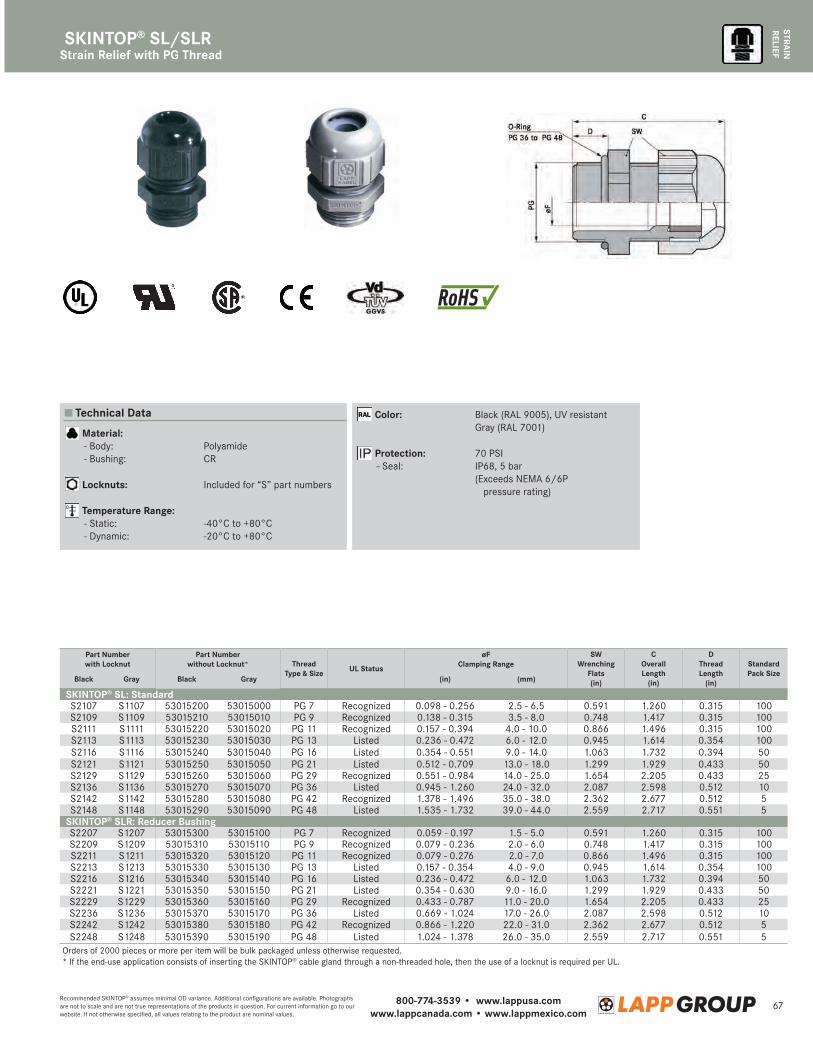
800-774-3539 • www.lappusa.comwww.lappcanada.com • www.lappmexico.com
67Recommended SKINTOP® assumes minimal OD variance. Additional configurations are available. Photographs are not to scale and are not true representations of the products in question. For current information go to our website. If not otherwise specified, all values relating to the product are nominal values.
STRAIN
RELIEFStrain Relief with PG Thread
SKINTOP® SL/SLR
Technical Data
Material: - Body: Polyamide - Bushing: CR
Locknuts: Included for “S” part numbers
Temperature Range: - Static: -40°C to +80°C - Dynamic: -20°C to +80°C
Color: Black (RAL 9005), UV resistant Gray (RAL 7001)
Protection: 70 PSI - Seal: IP68, 5 bar (E xceeds NEMA 6/6P
pressure rating)
Part Numberwith Locknut
Part Numberwithout Locknut* Thread
Type & Size UL Status
øF Clamping Range
SWWrenching
Flats(in)
COverallLength
(in)
DThread Length
(in)
Standard Pack Size
Black Gray Black Gray (in) (mm)
SKINTOP® SL: Standard S2107 S1107 53015200 53015000 PG 7 Recognized 0.098 - 0.256 2.5 - 6.5 0.591 1.260 0.315 100S2109 S1109 53015210 53015010 PG 9 Recognized 0.138 - 0.315 3.5 - 8.0 0.748 1.417 0.315 100S2111 S1111 53015220 53015020 PG 11 Recognized 0.157 - 0.394 4.0 - 10.0 0.866 1.496 0.315 100S2113 S1113 53015230 53015030 PG 13 Listed 0.236 - 0.472 6.0 - 12.0 0.945 1.614 0.354 100S2116 S1116 53015240 53015040 PG 16 Listed 0.354 - 0.551 9.0 - 14.0 1.063 1.732 0.394 50S2121 S1121 53015250 53015050 PG 21 Listed 0.512 - 0.709 13.0 - 18.0 1.299 1.929 0.433 50S2129 S1129 53015260 53015060 PG 29 Recognized 0.551 - 0.984 14.0 - 25.0 1.654 2.205 0.433 25S2136 S1136 53015270 53015070 PG 36 Listed 0.945 - 1.260 24.0 - 32.0 2.087 2.598 0.512 10S2142 S1142 53015280 53015080 PG 42 Recognized 1.378 - 1.496 35.0 - 38.0 2.362 2.677 0.512 5S2148 S1148 53015290 53015090 PG 48 Listed 1.535 - 1.732 39.0 - 44.0 2.559 2.717 0.551 5
SKINTOP® SLR: Reducer BushingS2207 S1207 53015300 53015100 PG 7 Recognized 0.059 - 0.197 1.5 - 5.0 0.591 1.260 0.315 100S2209 S1209 53015310 53015110 PG 9 Recognized 0.079 - 0.236 2.0 - 6.0 0.748 1.417 0.315 100S2211 S1211 53015320 53015120 PG 11 Recognized 0.079 - 0.276 2.0 - 7.0 0.866 1.496 0.315 100S2213 S1213 53015330 53015130 PG 13 Listed 0.157 - 0.354 4.0 - 9.0 0.945 1.614 0.354 100S2216 S1216 53015340 53015140 PG 16 Listed 0.236 - 0.472 6.0 - 12.0 1.063 1.732 0.394 50S2221 S1221 53015350 53015150 PG 21 Listed 0.354 - 0.630 9.0 - 16.0 1.299 1.929 0.433 50S2229 S1229 53015360 53015160 PG 29 Recognized 0.433 - 0.787 11.0 - 20.0 1.654 2.205 0.433 25S2236 S1236 53015370 53015170 PG 36 Listed 0.669 - 1.024 17.0 - 26.0 2.087 2.598 0.512 10S2242 S1242 53015380 53015180 PG 42 Recognized 0.866 - 1.220 22.0 - 31.0 2.362 2.677 0.512 5S2248 S1248 53015390 53015190 PG 48 Listed 1.024 - 1.378 26.0 - 35.0 2.559 2.717 0.551 5
Orders of 2000 pieces or more per item will be bulk packaged unless otherwise requested.* If the end-use application consists of inserting the SKINTOP® cable gland through a non-threaded hole, then the use of a locknut is required per UL.
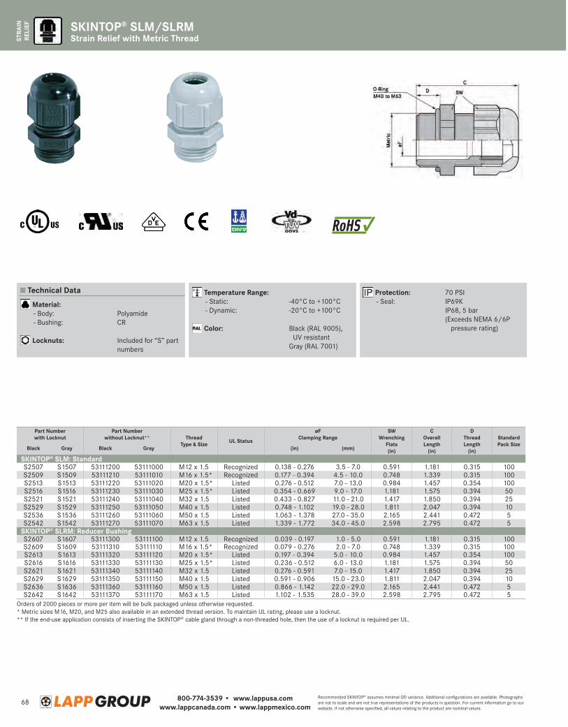
800-774-3539 • www.lappusa.comwww.lappcanada.com • www.lappmexico.com
68Recommended SKINTOP® assumes minimal OD variance. Additional configurations are available. Photographs are not to scale and are not true representations of the products in question. For current information go to our website. If not otherwise specified, all values relating to the product are nominal values.
STRA
IN
RELI
EF
Strain Relief with Metric ThreadSKINTOP® SLM/SLRM
Part Numberwith Locknut
Part Numberwithout Locknut** Thread
Type & Size UL Status
øFClamping Range
SWWrenching
Flats(in)
COverall Length
(in)
DThread Length
(in)
Standard Pack Size
Black Gray Black Gray (in) (mm)
SKINTOP® SLM: StandardS2507 S1507 53111200 53111000 M12 x 1.5 Recognized 0.138 - 0.276 3.5 - 7.0 0.591 1.181 0.315 100S2509 S1509 53111210 53111010 M16 x 1.5* Recognized 0.177 - 0.394 4.5 - 10.0 0.748 1.339 0.315 100S2513 S1513 53111220 53111020 M20 x 1.5* Listed 0.276 - 0.512 7.0 - 13.0 0.984 1.457 0.354 100S2516 S1516 53111230 53111030 M25 x 1.5* Listed 0.354 - 0.669 9.0 - 17.0 1.181 1.575 0.394 50S2521 S1521 53111240 53111040 M32 x 1.5 Listed 0.433 - 0.827 11.0 - 21.0 1.417 1.850 0.394 25S2529 S1529 53111250 53111050 M40 x 1.5 Listed 0.748 - 1.102 19.0 - 28.0 1.811 2.047 0.394 10S2536 S1536 53111260 53111060 M50 x 1.5 Listed 1.063 - 1.378 27.0 - 35.0 2.165 2.441 0.472 5S2542 S1542 53111270 53111070 M63 x 1.5 Listed 1.339 - 1.772 34.0 - 45.0 2.598 2.795 0.472 5
SKINTOP® SLRM: Reducer BushingS2607 S1607 53111300 53111100 M12 x 1.5 Recognized 0.039 - 0.197 1.0 - 5.0 0.591 1.181 0.315 100S2609 S1609 53111310 53111110 M16 x 1.5* Recognized 0.079 - 0.276 2.0 - 7.0 0.748 1.339 0.315 100S2613 S1613 53111320 53111120 M20 x 1.5* Listed 0.197 - 0.394 5.0 - 10.0 0.984 1.457 0.354 100S2616 S1616 53111330 53111130 M25 x 1.5* Listed 0.236 - 0.512 6.0 - 13.0 1.181 1.575 0.394 50S2621 S1621 53111340 53111140 M32 x 1.5 Listed 0.276 - 0.591 7.0 - 15.0 1.417 1.850 0.394 25S2629 S1629 53111350 53111150 M40 x 1.5 Listed 0.591 - 0.906 15.0 - 23.0 1.811 2.047 0.394 10S2636 S1636 53111360 53111160 M50 x 1.5 Listed 0.866 - 1.142 22.0 - 29.0 2.165 2.441 0.472 5S2642 S1642 53111370 53111170 M63 x 1.5 Listed 1.102 - 1.535 28.0 - 39.0 2.598 2.795 0.472 5
Orders of 2000 pieces or more per item will be bulk packaged unless otherwise requested.* Metric sizes M16, M20, and M25 also available in an extended thread version. To maintain UL rating, please use a locknut.** If the end-use application consists of inserting the SKINTOP® cable gland through a non-threaded hole, then the use of a locknut is required per UL.
Technical Data
Material: - Body: Polyamide - Bushing: CR
Locknuts: Included for “S” part numbers
Temperature Range: - Static: -40°C to +100°C - Dynamic: -20°C to +100°C
Color: B lack (RAL 9005), UV resistant
Gray (RAL 7001)
Protection: 70 PSI - Seal: IP69K IP68, 5 bar (E xceeds NEMA 6/6P
pressure rating)
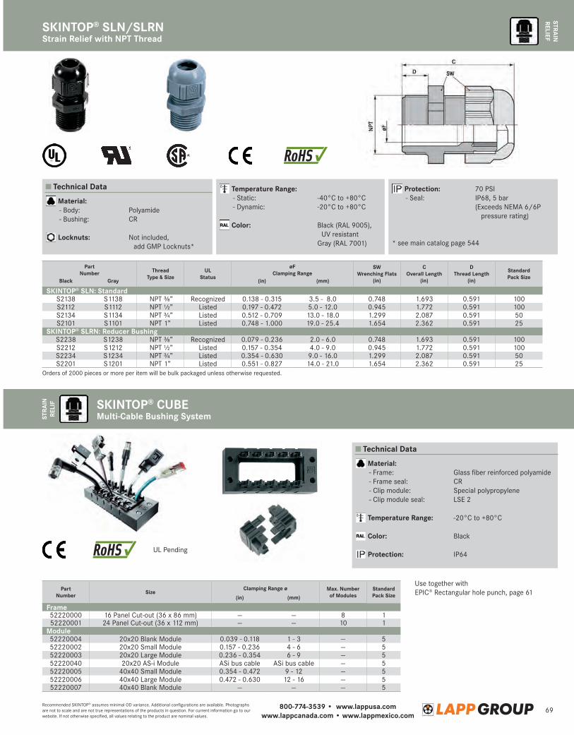
800-774-3539 • www.lappusa.comwww.lappcanada.com • www.lappmexico.com
69Recommended SKINTOP® assumes minimal OD variance. Additional configurations are available. Photographs are not to scale and are not true representations of the products in question. For current information go to our website. If not otherwise specified, all values relating to the product are nominal values.
STRAIN
RELIEF
SKINTOP® SLN/SLRNST
RAIN
RE
LIF SKINTOP® CUBE
Multi-Cable Bushing System
Strain Relief with NPT Thread
Technical Data
Technical Data
Material: - Body: Polyamide - Bushing: CR
Locknuts: N ot included, add GMP Locknuts*
Material: - Frame: Glass fiber reinforced polyamide - Frame seal: CR - Clip module: Special polypropylene - Clip module seal: LSE 2
Temperature Range: -20°C to +80°C
Color: Black
Protection: IP64
Temperature Range: - Static: -40°C to +80°C - Dynamic: -20°C to +80°C
Color: B lack (RAL 9005), UV resistant
Gray (RAL 7001)
Protection: 70 PSI - Seal: IP68, 5 bar (E xceeds NEMA 6/6P
pressure rating)
* see main catalog page 544
Part Number Size
Clamping Range ø Max. Numberof Modules
Standard Pack Size(in) (mm)
Frame52220000 16 Panel Cut-out (36 x 86 mm) — — 8 152220001 24 Panel Cut-out (36 x 112 mm) — — 10 1
Module52220004 20x20 Blank Module 0.039 - 0.118 1 - 3 — 552220002 20x20 Small Module 0.157 - 0.236 4 - 6 — 552220003 20x20 Large Module 0.236 - 0.354 6 - 9 — 552220040 20x20 AS-i Module ASi bus cable ASi bus cable — 552220005 40x40 Small Module 0.354 - 0.472 9 - 12 — 552220006 40x40 Large Module 0.472 - 0.630 12 - 16 — 552220007 40x40 Blank Module — — — 5
Part Number Thread
Type & SizeUL
Status
øF Clamping Range
SWWrenching Flats
(in)
COverall Length
(in)
DThread Length
(in)
Standard Pack Size
Black Gray (in) (mm)
SKINTOP® SLN: Standard S2138 S1138 NPT ⅜” Recognized 0.138 - 0.315 3.5 - 8.0 0.748 1.693 0.591 100S2112 S1112 NPT ½” Listed 0.197 - 0.472 5.0 - 12.0 0.945 1.772 0.591 100S2134 S1134 NPT ¾” Listed 0.512 - 0.709 13.0 - 18.0 1.299 2.087 0.591 50S2101 S1101 NPT 1” Listed 0.748 - 1.000 19.0 - 25.4 1.654 2.362 0.591 25
SKINTOP® SLRN: Reducer BushingS2238 S1238 NPT ⅜” Recognized 0.079 - 0.236 2.0 - 6.0 0.748 1.693 0.591 100S2212 S1212 NPT ½” Listed 0.157 - 0.354 4.0 - 9.0 0.945 1.772 0.591 100S2234 S1234 NPT ¾” Listed 0.354 - 0.630 9.0 - 16.0 1.299 2.087 0.591 50S2201 S1201 NPT 1” Listed 0.551 - 0.827 14.0 - 21.0 1.654 2.362 0.591 25
Orders of 2000 pieces or more per item will be bulk packaged unless otherwise requested.
UL Pending
Use together with EPIC® Rectangular hole punch, page 61
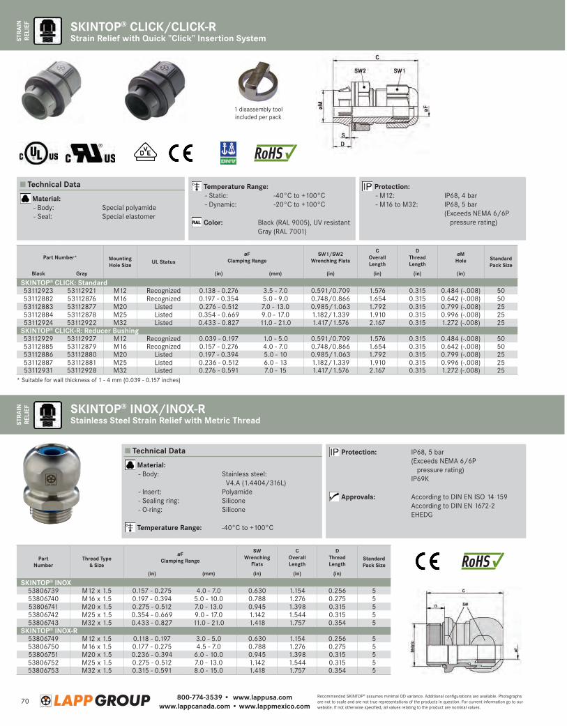
800-774-3539 • www.lappusa.comwww.lappcanada.com • www.lappmexico.com
70Recommended SKINTOP® assumes minimal OD variance. Additional configurations are available. Photographs are not to scale and are not true representations of the products in question. For current information go to our website. If not otherwise specified, all values relating to the product are nominal values.
STRA
IN
RELI
EFST
RAIN
RE
LIEF
SKINTOP® CLICK/CLICK-RStrain Relief with Quick ”Click” Insertion System
Part Number* Mounting Hole Size UL Status
øFClamping Range
SW1/SW2 Wrenching Flats
COverall Length
DThread Length
øM Hole Standard
Pack SizeBlack Gray (in) (mm) (in) (in) (in) (in)
SKINTOP® CLICK: Standard 53112923 53112921 M12 Recognized 0.138 - 0.276 3.5 - 7.0 0.591/0.709 1.576 0.315 0.484 (-.008) 5053112882 53112876 M16 Recognized 0.197 - 0.354 5.0 - 9.0 0.748/0.866 1.654 0.315 0.642 (-.008) 5053112883 53112877 M20 Listed 0.276 - 0.512 7.0 - 13.0 0.985/1.063 1.792 0.315 0.799 (-.008) 2553112884 53112878 M25 Listed 0.354 - 0.669 9.0 - 17.0 1.182/1.339 1.910 0.315 0.996 (-.008) 2553112924 53112922 M32 Listed 0.433 - 0.827 11.0 - 21.0 1.417/1.576 2.167 0.315 1.272 (-.008) 25
SKINTOP® CLICK-R: Reducer Bushing53112929 53112927 M12 Recognized 0.039 - 0.197 1.0 - 5.0 0.591/0.709 1.576 0.315 0.484 (-.008) 5053112885 53112879 M16 Recognized 0.157 - 0.276 4.0 - 7.0 0.748/0.866 1.654 0.315 0.642 (-.008) 5053112886 53112880 M20 Listed 0.197 - 0.394 5.0 - 10 0.985/1.063 1.792 0.315 0.799 (-.008) 2553112887 53112881 M25 Listed 0.236 - 0.512 6.0 - 13 1.182/1.339 1.910 0.315 0.996 (-.008) 2553112931 53112928 M32 Listed 0.276 - 0.591 7.0 - 15 1.417/1.576 2.167 0.315 1.272 (-.008) 25
1 disassembly tool included per pack
* Suitable for wall thickness of 1 - 4 mm (0.039 - 0.157 inches)
Technical Data
Material: - Body: Special polyamide - Seal: Special elastomer
Temperature Range: - Static: -40°C to +100°C - Dynamic: -20°C to +100°C
Color: Black (RAL 9005), UV resistant Gray (RAL 7001)
Protection: - M12: IP68, 4 bar - M16 to M32: IP68, 5 bar (E xceeds NEMA 6/6P
pressure rating)
SKINTOP® INOX/INOX-RStainless Steel Strain Relief with Metric Thread
Part Number
Thread Type & Size
øFClamping Range
SWWrenching
Flats
COverall Length
DThread Length
Standard Pack Size
(in) (mm) (in) (in) (in)
SKINTOP® INOX53806739 M12 x 1.5 0.157 - 0.275 4.0 - 7.0 0.630 1.154 0.256 553806740 M16 x 1.5 0.197 - 0.394 5.0 - 10.0 0.788 1.276 0.275 553806741 M20 x 1.5 0.275 - 0.512 7.0 - 13.0 0.945 1.398 0.315 553806742 M25 x 1.5 0.354 - 0.669 9.0 - 17.0 1.142 1.544 0.315 553806743 M32 x 1.5 0.433 - 0.827 11.0 - 21.0 1.418 1.757 0.354 5
SKINTOP® INOX-R53806749 M12 x 1.5 0.118 - 0.197 3.0 - 5.0 0.630 1.154 0.256 553806750 M16 x 1.5 0.177 - 0.275 4.5 - 7.0 0.788 1.276 0.275 553806751 M20 x 1.5 0.236 - 0.394 6.0 - 10.0 0.945 1.398 0.315 553806752 M25 x 1.5 0.275 - 0.512 7.0 - 13.0 1.142 1.544 0.315 553806753 M32 x 1.5 0.315 - 0.591 8.0 - 15.0 1.418 1.757 0.354 5
Technical Data
Material: - Body: S tainless steel:
V4.A (1.4404/316L) - Insert: Polyamide - Sealing ring: Silicone - O-ring: Silicone
Temperature Range: -40°C to +100°C
Protection: IP68, 5 bar (E xceeds NEMA 6/6P
pressure rating) IP69K
Approvals: According to DIN EN ISO 14 159 According to DIN EN 1672-2 EHEDG
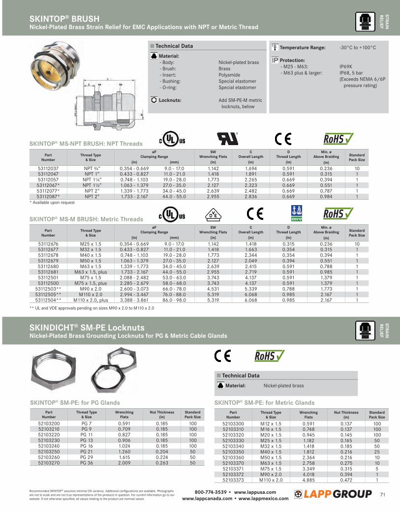
800-774-3539 • www.lappusa.comwww.lappcanada.com • www.lappmexico.com
71Recommended SKINTOP® assumes minimal OD variance. Additional configurations are available. Photographs are not to scale and are not true representations of the products in question. For current information go to our website. If not otherwise specified, all values relating to the product are nominal values.
STRAIN
RELIEF
SKINTOP® BRUSHNickel-Plated Brass Strain Relief for EMC Applications with NPT or Metric Thread
STRAIN
RELIEF
SKINDICHT® SM-PE LocknutsNickel-Plated Brass Grounding Locknuts for PG & Metric Cable Glands
** UL and VDE approvals pending on sizes M90 x 2.0 to M110 x 2.0
* Available upon request
Part Number
Thread Type & Size
øFClamping Range
SWWrenching Flats
COverall Length
DThread Length
Min. ø Above Braiding Standard
Pack Size(in) (mm) (in) (in) (in) (in)
53112037 NPT ¾” 0.354 - 0.669 9.0 - 17.0 1.142 1.694 0.591 0.236 1053112047 NPT 1” 0.433 - 0.827 11.0 - 21.0 1.418 1.891 0.591 0.315 153112057 NPT 1¼” 0.748 - 1.103 19.0 - 28.0 1.773 2.265 0.669 0.394 153112067* NPT 1½” 1.063 - 1.379 27.0 - 35.0 2.127 2.323 0.669 0.551 153112077* NPT 2” 1.339 - 1.773 34.0 - 45.0 2.639 2.482 0.669 0.787 153112087* NPT 2” 1.733 - 2.167 44.0 - 55.0 2.955 2.836 0.669 0.984 1
Part Number
Thread Type & Size
øFClamping Range
SWWrenching Flats
COverall Length
DThread Length
Min. ø Above Braiding Standard
Pack Size(in) (mm) (in) (in) (in) (in)
53112676 M25 x 1.5 0.354 - 0.669 9.0 - 17.0 1.142 1.418 0.315 0.236 1053112677 M32 x 1.5 0.433 - 0.827 11.0 - 21.0 1.418 1.663 0.354 0.315 153112678 M40 x 1.5 0.748 - 1.103 19.0 - 28.0 1.773 2.344 0.354 0.394 153112679 M50 x 1.5 1.063 - 1.379 27.0 - 35.0 2.127 2.049 0.394 0.551 153112680 M63 x 1.5 1.339 - 1.773 34.0 - 45.0 2.639 2.415 0.591 0.788 153112681 M63 x 1.5, plus 1.733 - 2.167 44.0 - 55.0 2.955 2.719 0.591 0.985 153112501 M75 x 1.5 2.088 - 2.482 53.0 - 63.0 3.743 4.137 0.591 1.379 153112500 M75 x 1.5, plus 2.285 - 2.679 58.0 - 68.0 3.743 4.137 0.591 1.379 1
53112503** M90 x 2.0 2.600 - 3.073 66.0 - 78.0 4.531 5.339 0.788 1.773 153112505** M110 x 2.0 2.994 - 3.467 76.0 - 88.0 5.319 6.068 0.985 2.167 153112504** M110 x 2.0, plus 3.388 - 3.861 86.0 - 98.0 5.319 6.068 0.985 2.167 1
Technical Data
Material: - Body: Nickel-plated brass - Brush: Brass - Insert: Polyamide - Bushing: Special elastomer - O-ring: Special elastomer
Locknuts: A dd SM-PE-M metric locknuts, below
Temperature Range: -30°C to +100°C
Protection: - M25 - M63: IP69K - M63 plus & larger: IP68, 5 bar (E xceeds NEMA 6/6P
pressure rating)
SKINTOP® MS-NPT BRUSH: NPT Threads
SKINTOP® MS-M BRUSH: Metric Threads
SKINTOP® SM-PE: for PG Glands SKINTOP® SM-PE: for Metric GlandsPart
NumberThread Type
& SizeWrenching
FlatsNut Thickness
(in)Standard Pack Size
52103200 PG 7 0.591 0.185 10052103210 PG 9 0.709 0.185 10052103220 PG 11 0.827 0.185 10052103230 PG 13 0.906 0.185 10052103240 PG 16 1.024 0.185 10052103250 PG 21 1.260 0.204 5052103260 PG 29 1.615 0.224 5052103270 PG 36 2.009 0.263 50
Part Number
Thread Type & Size
Wrenching Flats
Nut Thickness(in)
Standard Pack Size
52103300 M12 x 1.5 0.591 0.137 10052103310 M16 x 1.5 0.748 0.137 10052103320 M20 x 1.5 0.945 0.145 10052103330 M25 x 1.5 1.182 0.165 5052103340 M32 x 1.5 1.418 0.185 5052103350 M40 x 1.5 1.812 0.216 2552103360 M50 x 1.5 2.364 0.216 1052103370 M63 x 1.5 2.758 0.275 1052103371 M75 x 1.5 3.349 0.315 552103372 M90 x 2.0 4.018 0.394 152103373 M110 x 2.0 4.885 0.472 1
Technical Data
Material: Nickel-plated brass
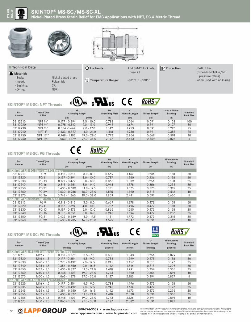
800-774-3539 • www.lappusa.comwww.lappcanada.com • www.lappmexico.com
72Recommended SKINTOP® assumes minimal OD variance. Additional configurations are available. Photographs are not to scale and are not true representations of the products in question. For current information go to our website. If not otherwise specified, all values relating to the product are nominal values.
STRA
IN
RELI
EF SKINTOP® MS-SC/MS-SC-XLNickel-Plated Brass Strain Relief for EMC Applications with NPT, PG & Metric Thread
PartNumber
Thread Type& Size
øFClamping Range
SWWrenching Flats
COverall Length
DThread Length
Min ø Above Braiding Standard
Pack Size(in) (mm) (in) (in) (in) (in)
SKINTOP® MS-SC: Standard PG Thread53112210 PG 9 0.118 - 0.315 3.0 - 8.0 0.669 1.142 0.236 0.158 5053112220 PG 11 0.157 - 0.394 4.0 - 10.0 0.787 1.260 0.236 0.158 5053112230 PG 13 0.197 - 0.472 5.0 - 12.0 0.866 1.339 0.256 0.158 2553112240 PG 16 0.315 - 0.551 8.0 - 14.0 0.945 1.378 0.256 0.236 2553112250 PG 21 0.433 - 0.689 11.0 - 17.5 1.181 1.575 0.275 0.315 2553112260 PG 29 0.630 - 0.985 16.0 - 25.0 1.575 1.890 0.315 0.512 1053112270 PG 36 0.748 - 1.260 19.0 - 32.0 1.969 2.441 0.591 0.630 5
SKINTOP® MS-SCL: Long PG Thread53112310 PG 9 0.118 - 0.315 3.0 - 8.0 0.669 1.378 0.472 0.158 5053112320 PG 11 0.157 - 0.394 4.0 - 10.0 0.787 1.496 0.472 0.158 5053112330 PG 13 0.197 - 0.472 5.0 - 12.0 0.866 1.555 0.472 0.158 2553112340 PG 16 0.315 - 0.551 8.0 - 14.0 0.945 1.594 0.472 0.236 2553112350 PG 21 0.433 - 0.689 11.0 - 17.5 1.181 1.772 0.472 0.315 2553112360 PG 29 0.630 - 0.985 16.0 - 25.0 1.575 2.047 0.591 0.512 10
PartNumber
Thread Type& Size
øFClamping Range
SWWrenching Flats
COverall Length
DThread Length
Min. ø Above Braiding Standard
Pack Size(in) (mm) (in) (in) (in) (in)
53112910 NPT ⅜” 0.177 - 0.394 4.5 - 10.0 0.788 1.564 0.591 0.158 10053112920 NPT ½” 0.275 - 0.512 7.0 - 13.0 0.945 1.674 0.591 0.197 5053112930 NPT ¾” 0.354 -0.669 9.0 - 17.0 1.142 1.753 0.591 0.296 2553112940 NPT 1” 0.433 - 0.827 11.0 - 21.0 1.418 1.930 0.591 0.355 2553112950 NPT 1¼” 0.748 - 1.103 19.0 - 28.0 1.773 2.264 0.669 0.591 1053112960 NPT 1½” 1.063 - 1.379 27.0 - 35.0 2.127 2.423 0.669 0.827 5
PartNumber
Thread Type& Size
øFClamping Range
SWWrenching Flats
COverall Length
DThread Length
Min ø Above Braiding Standard
Pack Size(inches) (mm) (inches) (inches) (inches) (inches)
SKINTOP® MS-M-SC: Standard Metric Thread53112610 M12 x 1.5 0.137 - 0.275 3.5 - 7.0 0.630 1.043 0.256 0.079 5053112620 M16 x 1.5 0.177 - 0.354 4.5 - 9.0 0.788 1.299 0.275 0.158 5053112630 M20 x 1.5 0.275 - 0.492 7.0 - 12.5 0.945 1.457 0.315 0.197 2553112640 M25 x 1.5 0.354 - 0.650 9.0 - 16.5 1.142 1.516 0.315 0.296 2553112650 M32 x 1.5 0.433 - 0.827 11.0 - 21.0 1.418 1.791 0.354 0.355 2553112660 M40 x 1.5 0.748 - 1.103 19.0 - 28.0 1.773 1.890 0.354 0.591 1053112670 M50 x 1.5 1.063 - 1.379 27.0 - 35.0 2.127 2.185 0.394 0.827 5
SKINTOP® MS-M-SCL: Long Metric Thread53112625 M16 x 1.5 0.177 - 0.354 4.5 - 9.0 0.788 1.496 0.472 0.158 5053112635 M20 x 1.5 0.275 - 0.492 7.0 - 12.5 0.945 1.614 0.472 0.197 2553112645 M25 x 1.5 0.354 - 0.650 9.0 - 16.5 1.142 1.673 0.472 0.296 2553112655 M32 x 1.5 0.433 - 0.827 11.0 - 21.0 1.418 2.028 0.591 0.355 2553112665 M40 x 1.5 0.748 - 1.103 19.0 - 28.0 1.773 2.126 0.591 0.591 1053112675 M50 x 1.5 1.063 - 1.379 27.0 - 35.0 2.127 2.382 0.591 0.827 5
SKINTOP® MS-SC: NPT Threads
SKINTOP® MS-SC: PG Threads
SKINTOP® MS-SC: PG Threads
Technical Data
Material: - Body: Nickel-plated brass - Insert: Polyamide - Bushing: CR - O-ring: NBR
Locknuts: A dd SM-PE locknuts, page 71
Temperature Range: -30°C to +100°C
Protection: IP68, 5 bar (E xceeds NEMA 6/6P
pressure rating) when used with an O-ring
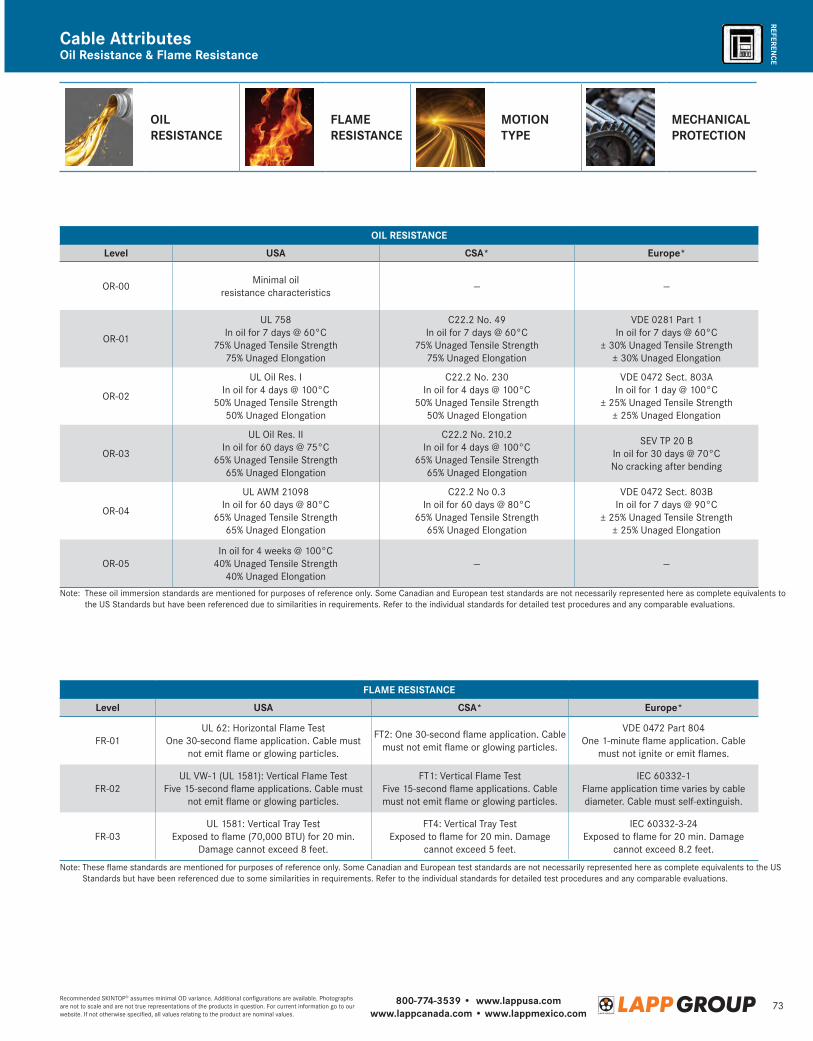
800-774-3539 • www.lappusa.comwww.lappcanada.com • www.lappmexico.com
73Recommended SKINTOP® assumes minimal OD variance. Additional configurations are available. Photographs are not to scale and are not true representations of the products in question. For current information go to our website. If not otherwise specified, all values relating to the product are nominal values.
REFERENCEOil Resistance & Flame ResistanceCable Attributes
OIL RESISTANCE
FLAME RESISTANCE
MOTION TYPE
MECHANICAL PROTECTION
OIL RESISTANCE
Level USA CSA* Europe*
OR-00Minimal oil
resistance characteristics— —
OR-01
UL 758 In oil for 7 days @ 60°C
75% Unaged Tensile Strength75% Unaged Elongation
C22.2 No. 49In oil for 7 days @ 60°C
75% Unaged Tensile Strength75% Unaged Elongation
VDE 0281 Part 1In oil for 7 days @ 60°C
± 30% Unaged Tensile Strength± 30% Unaged Elongation
OR-02
UL Oil Res. IIn oil for 4 days @ 100°C
50% Unaged Tensile Strength50% Unaged Elongation
C22.2 No. 230 In oil for 4 days @ 100°C
50% Unaged Tensile Strength50% Unaged Elongation
VDE 0472 Sect. 803AIn oil for 1 day @ 100°C
± 25% Unaged Tensile Strength± 25% Unaged Elongation
OR-03
UL Oil Res. IIIn oil for 60 days @ 75°C
65% Unaged Tensile Strength65% Unaged Elongation
C22.2 No. 210.2In oil for 4 days @ 100°C
65% Unaged Tensile Strength65% Unaged Elongation
SEV TP 20 BIn oil for 30 days @ 70°CNo cracking after bending
OR-04
UL AWM 21098In oil for 60 days @ 80°C
65% Unaged Tensile Strength65% Unaged Elongation
C22.2 No 0.3In oil for 60 days @ 80°C
65% Unaged Tensile Strength65% Unaged Elongation
VDE 0472 Sect. 803BIn oil for 7 days @ 90°C
± 25% Unaged Tensile Strength± 25% Unaged Elongation
OR-05In oil for 4 weeks @ 100°C
40% Unaged Tensile Strength40% Unaged Elongation
— —
Note: These oil immersion standards are mentioned for purposes of reference only. Some Canadian and European test standards are not necessarily represented here as complete equivalents to the US Standards but have been referenced due to similarities in requirements. Refer to the individual standards for detailed test procedures and any comparable evaluations.
FLAME RESISTANCE
Level USA CSA* Europe*
FR-01UL 62: Horizontal Flame Test
One 30-second flame application. Cable must not emit flame or glowing particles.
FT2: One 30-second flame application. Cable must not emit flame or glowing particles.
VDE 0472 Part 804One 1-minute flame application. Cable
must not ignite or emit flames.
FR-02UL VW-1 (UL 1581): Vertical Flame Test
Five 15-second flame applications. Cable must not emit flame or glowing particles.
FT1: Vertical Flame TestFive 15-second flame applications. Cable must not emit flame or glowing particles.
IEC 60332-1Flame application time varies by cable diameter. Cable must self-extinguish.
FR-03UL 1581: Vertical Tray Test
Exposed to flame (70,000 BTU) for 20 min. Damage cannot exceed 8 feet.
FT4: Vertical Tray TestExposed to flame for 20 min. Damage
cannot exceed 5 feet.
IEC 60332-3-24Exposed to flame for 20 min. Damage
cannot exceed 8.2 feet.
Note: These flame standards are mentioned for purposes of reference only. Some Canadian and European test standards are not necessarily represented here as complete equivalents to the US Standards but have been referenced due to some similarities in requirements. Refer to the individual standards for detailed test procedures and any comparable evaluations.
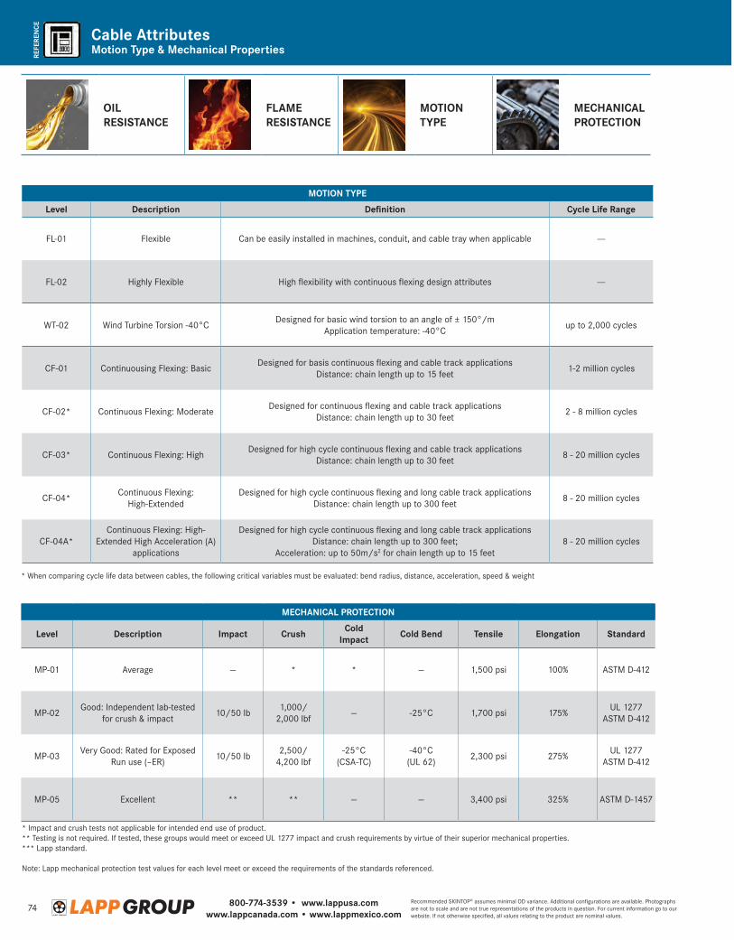
800-774-3539 • www.lappusa.comwww.lappcanada.com • www.lappmexico.com
74Recommended SKINTOP® assumes minimal OD variance. Additional configurations are available. Photographs are not to scale and are not true representations of the products in question. For current information go to our website. If not otherwise specified, all values relating to the product are nominal values.
REFE
REN
CE
Motion Type & Mechanical PropertiesCable Attributes
MOTION TYPE
Level Description Definition Cycle Life Range
FL-01 Flexible Can be easily installed in machines, conduit, and cable tray when applicable ---
FL-02 Highly Flexible High flexibility with continuous flexing design attributes ---
WT-02 Wind Turbine Torsion -40°CDesigned for basic wind torsion to an angle of ± 150°/m
Application temperature: -40°Cup to 2,000 cycles
CF-01 Continuousing Flexing: BasicDesigned for basis continuous flexing and cable track applications
Distance: chain length up to 15 feet1-2 million cycles
CF-02* Continuous Flexing: ModerateDesigned for continuous flexing and cable track applications
Distance: chain length up to 30 feet2 - 8 million cycles
CF-03* Continuous Flexing: HighDesigned for high cycle continuous flexing and cable track applications
Distance: chain length up to 30 feet8 - 20 million cycles
CF-04*Continuous Flexing:
High-ExtendedDesigned for high cycle continuous flexing and long cable track applications
Distance: chain length up to 300 feet8 - 20 million cycles
CF-04A*Continuous Flexing: High-
Extended High Acceleration (A)applications
Designed for high cycle continuous flexing and long cable track applicationsDistance: chain length up to 300 feet;
Acceleration: up to 50m/s2 for chain length up to 15 feet8 - 20 million cycles
* When comparing cycle life data between cables, the following critical variables must be evaluated: bend radius, distance, acceleration, speed & weight
MECHANICAL PROTECTION
Level Description Impact Crush Cold Impact Cold Bend Tensile Elongation Standard
MP-01 Average — * * — 1,500 psi 100% ASTM D-412
MP-02Good: Independent lab-tested
for crush & impact10/50 lb
1,000/ 2,000 lbf
— -25°C 1,700 psi 175%UL 1277
ASTM D-412
MP-03Very Good: Rated for Exposed
Run use (–ER)10/50 lb
2,500/ 4,200 lbf
-25°C (CSA-TC)
-40°C(UL 62)
2,300 psi 275%UL 1277
ASTM D-412
MP-05 Excellent ** ** — — 3,400 psi 325% ASTM D-1457
* Impact and crush tests not applicable for intended end use of product.** Testing is not required. If tested, these groups would meet or exceed UL 1277 impact and crush requirements by virtue of their superior mechanical properties. *** Lapp standard.
Note: Lapp mechanical protection test values for each level meet or exceed the requirements of the standards referenced.
OIL RESISTANCE
FLAME RESISTANCE
MOTION TYPE
MECHANICAL PROTECTION

800-774-3539 • www.lappusa.comwww.lappcanada.com • www.lappmexico.com
75Recommended SKINTOP® assumes minimal OD variance. Additional configurations are available. Photographs are not to scale and are not true representations of the products in question. For current information go to our website. If not otherwise specified, all values relating to the product are nominal values.
REFERENCEColor Code ChartsChart 1
Conductor Color
1 black
2 white
3 red
4 green
5 orange
6 blue
7 white/black
8 red/black
9 green/black
10 orange/black
11 blue/black
12 black/white
13 red/white
14 green/white
15 blue/white
16 black/red
Conductor Color
17 white /red
18 orange/red
19 blue/red
20 red/green
21 orange/green
22 black/white/red
23 white/black/red
24 red/black/white
25 green/black/white
26 orange/black/white
27 blue/black/white
28 black/red/green
29 white/red/green
30 red/black/green
31 green/black/orange
32 orange/black/green
Conductor Color
33 blue/white/orange
34 black/white/orange
35 white/red/orange
36 orange/white/blue
37 white/red/blue
38 black/white/green
39 white/black/green
40 red/white/green
41 green/white/blue
42 orange/red/green
43 blue/red/green
44 black/white/blue
45 white/black/blue
46 red/white/blue
47 green/orange/red
48 orange/red/blue
Conductor Color
49 blue/orange/red
50 black/orange/red
51 white/black/orange
52 red/orange/black
53 green/red/blue
54 orange/black/blue
55 blue/black/orange
56 black/orange/green
57 white/orange/green
58 red/orange/green
59 green/black/blue
60 orange/green/blue
61 black/orange/blue
Pair Color
1 black + red
2 black + white
3 black + green
4 black + blue
5 black + yellow
6 black + brown
7 black + orange
8 red + white
9 red + green
10 red + blue
11 red + yellow
12 red + brown
13 red + orange
Pair Color
14 green + white
15 green + blue
16 green + yellow
17 green + brown
18 green + orange
19 white + blue
20 white + yellow
21 white + brown
22 white + orange
23 blue + yellow
24 blue + brown
25 blue + orange
26 brown + yellow
Pair Color
27 brown + orange
28 orange + yellow
29 violet + orange
30 violet + red
31 violet + white
32 violet + dark green
33 violet + light blue
34 violet + yellow
35 violet + brown
36 violet + black
37 gray + white
Conductor Color
1 black
2 white
3 red
4 green*
Conductor Color
5 brown
6 blue
7 orange
8 yellow
Conductor Color
9 violet
10 gray
11 pink
12 tan
* Cables with CE approval have green/yellow conductor for #4Numbers are spaced 20 - 55 mm apart and are inverted with underline
ÖLFLEX® 590 P/CP, C 304, C 304 S, D304 OS
C 304, C 304 S, UNITRONIC® 190/190 CY
D 304 IS, D 304 OS, UNITRONIC® CY (TP) plus
Chart 2
Chart 3

800-774-3539 • www.lappusa.comwww.lappcanada.com • www.lappmexico.com
76Recommended SKINTOP® assumes minimal OD variance. Additional configurations are available. Photographs are not to scale and are not true representations of the products in question. For current information go to our website. If not otherwise specified, all values relating to the product are nominal values.
REFE
REN
CE
Chart 4Color Code Charts
Conductor Color
1 white
2 brown
3 green
4 yellow
5 gray
6 pink
7 blue
8 red
9 black
10 violet
11 gray/pink
12 red/blue
13 white/green
14 brown/green
15 white/yellow
16 yellow/brown
Conductor Color
17 white/gray
18 gray/brown
19 white/pink
20 pink/brown
21 white/blue
22 brown/blue
23 white/red
24 brown/red
25 white/black
26 brown/black
27 gray/green
28 yellow/gray
29 pink/green
30 yellow/pink
31 green/blue
32 yellow/blue
Conductor Color
33 green/red
34 yellow/red
35 green/black
36 yellow/black
37 gray/blue
38 pink/blue
39 gray/red
40 pink/red
41 gray/black
42 pink/black
43 blue/black
44 red/black
45 white/brown/black
46 yellow/green/black
47 gray/pink/black
48 red/blue/black
Conductor Color
49 white/green/black
50 brown/green/black
51 white/yellow/black
52 yellow/brown/black
53 white/gray/black
54 gray/brown/black
55 white/pink/black
56 pink/brown/black
57 white/blue/black
58 brown/blue/black
59 white/red/black
60 brown/red/black
61 black/white
UNITRONIC® BUS CAN/CAN FD
Chart 8: DIN 47100 Without Color Repetition (for telephone & electronic use only)
Conductor Color
27 white/black/yellow
28 white/black/blue
29 white/black/brown
30 white/black/orange
31 white/black/gray
32 white/black/violet
33 white/black/black
34 white/red/black
35 white/red/red
36 white/red/green
37 white/red/blue
38 white/red/brown
39 white/red/violet
Conductor Color
40 white/green/black
41 white/green/red
42 white/green/green
43 white/green/blue
44 white/green/brown
45 white/green/violet
46 white/blue/black
47 white/blue/red
48 white/blue/green
49 white/blue/blue
50 white/blue/brown
Conductor Color
1 black
2 brown
3 red
4 orange
5 yellow
6 green
7 blue
8 violet
9 gray
10 white
11 white/black
12 white/brown
13 white/red
Conductor Color
14 white/orange
15 white/yellow
16 white/green
17 white/blue
18 white/violet
19 white/gray
20 white/black/brown
21 white/black/red
22 white/black/orange
23 white/black/yellow
24 white/black/green
25 white/black/blue
26 white/black/violet
Conductor Color
27 white/black/gray
28 white/brown/red
29 white/brown/orange
30 white/brown/yellow
31 white/brown/green
32 white/brown/blue
33 white/brown/violet
34 white/brown/gray
35 white/red/orange
36 white/red/yellow
37 white/red/green
38 white/red/blue
39 white/red/violet
Conductor Color
40 white/red/gray
41 white/orange/yellow
42 white/orange/green
43 white/orange/blue
44 white/orange/violet
45 white/orange/gray
46 white/yellow/green
47 white/yellow/blue
48 white/yellow/violet
49 white/yellow/gray
50 white/green/blue
Conductor Color
14 red/yellow
15 red/black
16 white/black
17 white/red
18 white/green
19 white/yellow
20 white/blue
21 white/brown
22 white/orange
23 white/gray
24 white/violet
25 white/black/red
26 white/black/green
Conductor Color
1 black
2 red
3 white
4 green
5 orange
6 blue
7 brown
8 yellow
9 violet
10 gray
11 pink
12 tan
13 red/green
UNITRONIC® 300/300 S (24 - 22 AWG)
UNITRONIC® 300/300 S (20 - 16 AWG)
Chart 5
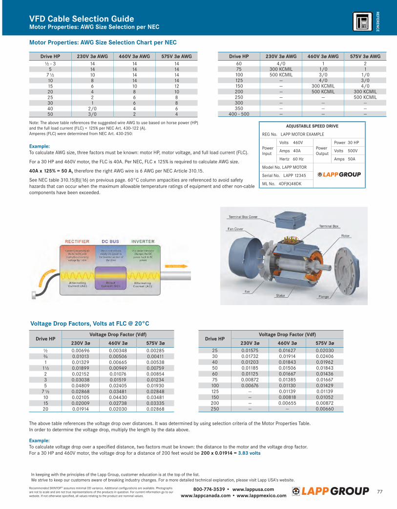
800-774-3539 • www.lappusa.comwww.lappcanada.com • www.lappmexico.com
77Recommended SKINTOP® assumes minimal OD variance. Additional configurations are available. Photographs are not to scale and are not true representations of the products in question. For current information go to our website. If not otherwise specified, all values relating to the product are nominal values.
REFERENCEMotor Properties: AWG Size Selection per NECVFD Cable Selection Guide
Example: To calculate AWG size, three factors must be known: motor HP, motor voltage, and full load current (FLC).
For a 30 HP and 460V motor, the FLC is 40A. Per NEC, FLC x 125% is required to calculate AWG size.
40A x 125% = 50 A, therefore the right AWG wire is 6 AWG per NEC Article 310.15.
See NEC table 310.15(B)(16) on previous page. 60°C column ampacities are referenced to avoid safety hazards that can occur when the maximum allowable temperature ratings of equipment and other non-cable components have been exceeded.
ADJUSTABLE SPEED DRIVE
REG No. LAPP MOTOR EXAMPLE
Power Input
Volts 460VPower Output
Power 30 HP
Amps 40A Volts 500V
Hertz 60 Hz Amps 50A
Model No. LAPP MOTOR
Serial No. LAPP 12345
ML No. 4DFJKJ48DK
Motor Properties: AWG Size Selection Chart per NEC
Drive HP 230V 3ø AWG 460V 3ø AWG 575V 3ø AWG½ - 3 14 14 14
5 14 14 147 ½ 10 14 1410 8 14 1415 6 10 1220 4 8 1025 2 6 830 1 6 840 2/0 4 650 3/0 2 4
Note: The above table references the suggested wire AWG to use based on horse power (HP) and the full load current (FLC) × 125% per NEC Art. 430-122 (A). Amperes (FLC) were determined from NEC Art. 430-250:
Drive HP 230V 3ø AWG 460V 3ø AWG 575V 3ø AWG60 4/0 1 275 300 KCMIL 1/0 1
100 500 KCMIL 3/0 1/0125 — 4/0 3/0150 — 300 KCMIL 4/0200 — 500 KCMIL 300 KCMIL250 — — 500 KCMIL300 — — —350 — — —
400 - 500 — — —
Drive HPVoltage Drop Factor (Vdf)
230V 3ø 460V 3ø 575V 3ø½ 0.00696 0.00348 0.00285¾ 0.01013 0.00506 0.004111 0.01329 0.00665 0.00538
1½ 0.01899 0.00949 0.007592 0.02152 0.01076 0.008543 0.03038 0.01519 0.012345 0.04809 0.02405 0.01930
7 ½ 0.02868 0.03481 0.0284810 0.02105 0.04430 0.0348115 0.02009 0.02738 0.0333520 0.01914 0.02030 0.02868
Voltage Drop Factors, Volts at FLC @ 20°C
The above table references the voltage drop over distances. It was determined by using selection criteria of the Motor Properties Table. In order to determine the voltage drop, multiply the length by the data above.
Example: To calculate voltage drop over a specified distance, two factors must be known: the distance to the motor and the voltage drop factor. For a 30 HP and 460V motor, the voltage drop for a distance of 200 feet would be 200 x 0.01914 = 3.83 volts
In keeping with the principles of the Lapp Group, customer education is at the top of the list. We strive to keep our customers aware of breaking industry changes. For a more detailed technical explanation, please visit Lapp USA’s website.
Drive HPVoltage Drop Factor (Vdf)
230V 3ø 460V 3ø 575V 3ø25 0.01575 0.01627 0.0203030 0.01732 0.01914 0.0240640 0.01203 0.01843 0.0196250 0.01185 0.01506 0.0184360 0.01125 0.01667 0.0143675 0.00872 0.01385 0.01667
100 0.00676 0.01130 0.01429125 — 0.01139 0.01139150 — 0.00818 0.01052200 — 0.00655 0.00872250 — — 0.00660
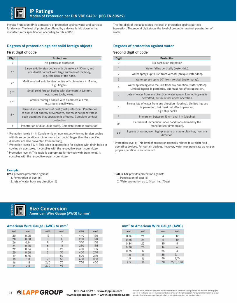
800-774-3539 • www.lappusa.comwww.lappcanada.com • www.lappmexico.com
78Recommended SKINTOP® assumes minimal OD variance. Additional configurations are available. Photographs are not to scale and are not true representations of the products in question. For current information go to our website. If not otherwise specified, all values relating to the product are nominal values.
REFE
REN
CERE
FERE
NCE
Modes of Protection per DIN VDE 0470-1 (IEC EN 60529)
American Wire Gauge (AWG) to mm2
IP Ratings
Size Conversion
Ingress Protection (IP) is a measure of protection against water and particles for devices. The level of protection offered by a device is laid down in the manufacturer’s specification according to DIN 40050.
The first digit of the code states the level of protection against particle ingression. The second digit states the level of protection against penetration of water.
Degrees of protection against solid foreign objects
First digit of codeDigit Protection
0 No particular protection
1*Large solid foreign bodies with diameters ≥ 50 mm, and
accidental contact with large surfaces of the body, e.g.: the back of the hand.
2*Medium-sized solid foreign bodies with diameters ≥ 12 mm,
e.g.: fingers.
3*°Small solid foreign bodies with diameters ≥ 2.5 mm,
e.g.: some tools, wires.
4*°Granular foreign bodies with diameters ≥ 1 mm,
e.g.: tools, small wires.
5•
Harmful accumulations of dust (dust protection). Penetration of dust is not entirely preventative, but must not penetrate in such quantities that operation is affected. Complete contact
protection.
6 Penetration of dust (dust-proof). Complete contact protection.
* Protection levels 1 - 4: Consistently or inconsistently formed foreign bodies with three perpendicular dimensions (i.e.: cubic) larger than the specified diameter are also prevented from entering.
° Protection levels 3 & 4: This table is appropriate for devices with drain holes or cooling air apertures. It complies with the respective expert committee.
• Protection level 5: This table is appropriate for devices with drain holes. It complies with the respective expert committee.
Degrees of protection against water
Second digit of codeDigit Protection
0 No particular protection
1 Water falling vertically (water drip).
2 Water sprays up to 15° from vertical (oblique water drip).
3 Water sprays up to 60° from vertical (water spray).
4Water splashing onto the unit from any direction (water splash).
Limited ingress is permitted, but must not affect operation.
5Jets of water from any direction (water spray). Limited ingress is
permitted, but must not affect operation.
6Strong jets of water from any direction (flooding). Limited ingress
is permitted, but must not affect operation, e.g.: ship decks
7 Immersion between 15 cm and 1 m (dipping).
8† Permanent immersion under conditions defined by the manufacturer (immersion).
9 KIngress of water, even high-pressure or steam cleaning, from any
direction.
† Protection level 8: This level of protection normally relates to air-tight field-operating devices. For certain devices, however, water may penetrate as long as proper operation is not affected.
Ex ample: IP65 provides protection against: 1. Penetration of dust (6) 2. Jets of water from any direction (5)
IP68, 5 bar provides protection against: 1. Penetration of dust (6) 2. Water protection up to 5 bar, i.e.: 70 psi
American Wire Gauge (AWG) to mm2
AWG mm2
30 0.0528 0.0826 0.1424 0.2522 0.3420 0.5019 0.7518 1.016 1.514 2.5
AWG mm2
12 410 68 106 164 252 351 50
1/0 502/0 703/0 95
AWG mm2
4/0 120250 120300 150350 185400 185450 240500 240600 300750 400
mm2 to American Wire Gauge (AWG)mm2 AWG
0.14 260.25 240.34 220.50 200.75 191.0 181.5 162.5 14
mm2 AWG
4 126 1010 816 625 435 2, 150 1/070 2/0, 3/0
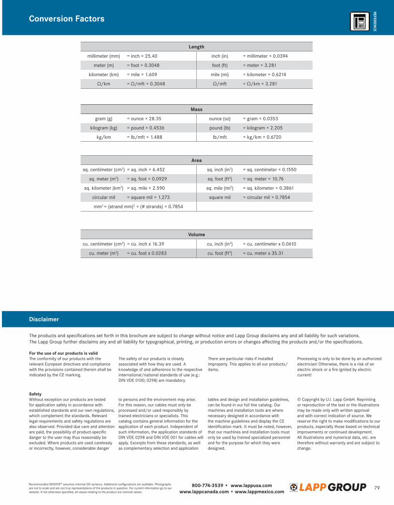
800-774-3539 • www.lappusa.comwww.lappcanada.com • www.lappmexico.com
79Recommended SKINTOP® assumes minimal OD variance. Additional configurations are available. Photographs are not to scale and are not true representations of the products in question. For current information go to our website. If not otherwise specified, all values relating to the product are nominal values.
REFERENCE
The products and specifications set forth in this brochure are subject to change without notice and Lapp Group disclaims any and all liability for such variations.The Lapp Group further disclaims any and all liability for typographical, printing, or production errors or changes affecting the products and/or the specifications.
For the use of our products is validThe conformity of our products with the relevant European directives and compliance with the provisions contained therein shall be indicated by the CE marking.
The safety of our products is closely associated with how they are used. A knowledge of and adherence to the respective international/national standards of use (e.g.: DIN VDE 0100; 0298) are mandatory.
There are particular risks if installed improperly. This applies to all our products/items.
Processing is only to be done by an authorized electrician! Otherwise, there is a risk of an electric shock or a fire ignited by electric current!
SafetyWithout exception our products are tested for application safety in accordance with established standards and our own regulations, which complement the standards. Relevant legal requirements and safety regulations are also observed. Provided due care and attention are paid, the possibility of product-specific danger to the user may thus reasonably be excluded. Where products are used carelessly or incorrectly, however, considerable danger
to persons and the environment may arise. For this reason, our cables must only be processed and/or used responsibly by trained electricians or specialists. This catalog contains general information for the application of each product. Independent of such information, the application standards of DIN VDE 0298 and DIN VDE 001 for cables will apply. Excerpts from these standards, as well as complementary selection and application
tables and design and installation guidelines, can be found in our full line catalog. Our machines and installation tools are where necessary designed in accordance with the machine guidelines and display the CE identification mark. It must be noted, however, that our machines and installation tools must only be used by trained specialized personnel and for the purpose for which they were designed.
© Copyright by U.I. Lapp GmbH. Reprinting or reproduction of the text or the illustrations may be made only with written approval and with correct indication of source. We reserve the right to make modifications to our products, especially those based on technical improvements or continued development. All illustrations and numerical data, etc. are therefore without warranty and are subject to change.
Length
millimeter (mm) = inch × 25.40 inch (in) = millimeter × 0.0394
meter (m) = foot × 0.3048 foot (ft) = meter × 3.281
kilometer (km) = mile × 1.609 mile (mi) = kilometer × 0.6214
Ω/km = Ω/mft × 0.3048 Ω/mft = Ω/km × 3.281
Volume
cu. centimeter (cm3) = cu. inch x 16.39 cu. inch (in3) = cu. centimeter x 0.0610
cu. meter (m3) = cu. foot x 0.0283 cu. foot (ft3) = cu. meter x 35.31
Mass
gram (g) = ounce × 28.35 ounce (oz) = gram × 0.0353
kilogram (kg) = pound × 0.4536 pound (lb) = kilogram × 2.205
kg/km = lb/mft × 1.488 lb/mft = kg/km × 0.6720
Area
sq. centimeter (cm2) = sq. inch × 6.452 sq. inch (in2) = sq. centimeter × 0.1550
sq. meter (m2) = sq. foot × 0.0929 sq. foot (ft2) = sq. meter × 10.76
sq. kilometer (km2) = sq. mile × 2.590 sq. mile (mi2) = sq. kilometer × 0.3861
circular mil = square mil × 1.273 square mil = circular mil × 0.7854
mm2 = (strand mm)2 × (# strands) × 0.7854
Conversion Factors
Disclaimer
To contact your local Lapp Group representative please visit www.lappgroup.com/worldwide
www.lappusa.com • www.lappcanada.comTerms of Trade:Our general conditions of sale can be downloaded from our website http://lappusa.lappgroup.com/terms-conditions.html
ÖLFLEX®
UNITRONIC®
HITRONIC®
SKINTOP®EPIC®
SILVYN®
FLEXIMARK®
ETHERLINE®
03/1
4. 1
0,00
0. 9
9090
195