lifa air secure box method for chilled beam cleaning
TRANSCRIPT
Vesa-Jukka Leppälä
Lifa Air Secure Box method for chilled beam cleaning
Helsinki Metropolia University of Applied Sciences
Bachelor of Engineering
Mechanical and Energy
Thesis
1 May 2014

Acknowledgements
This project was done as final thesis for Metropolia University of Applied Sciences, in
Mechanical Engineering program. Working with the thesis was started in January 2014
for Lifa Air Ltd. Supervisors for this project was Pekka Salonen from Metropolia Univer-
sity and Kimmo Haapalainen from Lifa Air Ltd.
I would like to acknowledge and thank Lifa Air Ltd for giving me the opportunity to work
my final thesis for them. In addition I would like to thank all personnel of Lifa Air Ltd,
who helped me to gather necessary information through the project.
2014, Espoo Finland
Vesa Leppälä

Abstract
Author(s) Title
Number of Pages Date
Vesa-Jukka Leppälä Lifa Air Secure Box
21 pages + 8 appendices 1 May 2014
Degree Bachelor of Engineering
Degree Programme Mechanical Engineering
Specialisation option Energy Engineering
Instructor(s) Kimmo Haapalainen, MSc in Philosophy, Marketing Director Pekka Salonen, Principal Lecturer
The objective of this Bachelor’s Thesis was to introduce a chilled beam cleaning method and to develop an improved version for the prototype introduced in 2011. This thesis was commissioned by Lifa Air Ltd. The company itself is specialized in improving Indoor Air quality and offers a wide range of products meant for ventilation cleaning. The aim for the development work was to fill the requirements and needs set by the company based on the research done, and to construct a working and improved prototype.
The research was started by gathering information from the previous versions of the prod-uct. All data was obtained by interviewing and studying all the research. This was followed by brainstorming and sketching which were finally modelled with a Solidworks 3D software. Once a preliminary version was modelled, the construction of a prototype could be started. While the prototype was under construction, all needs for improvements were noted and updated in 3D model. This method ensured that the prototype would be close enough to the production version. The testing of the prototype was performed as it was constructed.
As a result a 3D model, technical drawings and a working prototype were achieved. Based on the model and drawings, the production version for the final product can be manufac-tured. The project worked also as a learning process for understanding the steps and chal-lenges of a product development process.
Keywords Chilled beam, Convector, Ventilation hygiene, Secure Box, IAQ,

Contents
Abstract
List of Abbreviations
1 Introduction 1
1.1 Background 1
1.2 Aims & objectives 2
1.3 Project scope 2
1.4 Methodology 2
2 Literature review 3
2.1 Ventilation and air quality 3
2.2 Importance of hospital IAQ 4
2.3 Infection risks due to cleaning of ventilation 5
2.4 Maintaining the purity and proper working condition 5
2.5 Need for chilled beam cleaning 6
2.6 Methods for cleaning chilled beams 7
2.6.1 Comparison of methods 8
3 Design 9
3.1 Studying first prototype 9
3.2 Designing 10
3.3 Material selection 10
3.3.1 Material suppliers 11
3.4 Design progression 11
3.5 Working on prototype 12

4 Product testing 14
4.1 Equipment used 15
4.2 Testing 16
4.3 Taking readings 17
5 Final evaluation and conclusions 20
6 Bibliography 21
Appendices
Appendix 1. Sketching method for sliding profiles
Appendix 2. Sketching of product telescopic properties
Appendix 3. Sketching improvements during construction
Appendix 4. Preliminary 1 3D design from construction
Appendix 5. Decided drywall lifter
Appendix 6. Assembled product drawing
Appendix 8. Detailed C-profile drawing

List of Abbreviations
VTT Finnish government research center
TAYS Tampere University Hospital
IAQ Indoor Air Quality
ppm Particles per million, where 10000 ppm is same than 1%
pa SI Unit, pressure
InH2O Imperial unit, pressure
HEPA High efficiency particulate air filter
3G Filter developed by Lifa Air Ltd. Filter efficiency up to 99.99%
HC1100 HEPA Clean 1100, product of Lifa Air Ltd
PC Polycarbonate, plastic
AISI 304 Austenitic stainless steel according North-American standard
kg Weight (kilogram)
m Dimension (meter)
mm Dimension (millimeter)
µm Dimension (micrometer)
DS SW SolidWorks is a program developed by Dassault System. Program is
used for making dimensional drawings out from 3D models created.
3D Three dimensions

1
1 Introduction
This chapter is a walk through for the study and why it was made. This will also explain
the aims, objectives and scopes for the project, and give general understanding for the
problem studied.
1.1 Background
As technology improves, the awareness of poor indoor air quality and its health effects
increases. For years there have been studies about how hospital environment air quali-
ty affects directly to the possibility for getting infections. Hospitals have daily routines
for using disinfectants in the rooms where sick people have been held. The reason for
the surface disinfecting hasn’t been so effective is the bacteria and pollutants spread-
ing through the ventilation system. The main problem are the chilled beams, which will
gather dust and moisture from the ventilation and surrounding room. This will act as a
perfect breeding ground for bacteria (Työterveyslaitos, 2011).
Lifa Air Ltd has already invented a way to clean these beams while hospital depart-
ments can be open during the cleaning session, and there is no need for removing
these beams from their places. The invention has been called as a Secure Box. This
thesis will concentrate on the methods the chilled beam have been cleaned, and espe-
cially for the Secure Box method. The goal is to manufacture updated and more user-
friendly product of the Secure Box, and test it on the field.

2
1.2 Aims & objectives
Aim of the project is to construct a working prototype of Lifa Secure Box and taking into
account the shortcomings of the previous prototype.
The objectives are:
to analyze the theory behind chilled beam cleaning,
to investigate and compare methods for chilled beam cleaning,
to design and manufacture working prototype of the final product and
to evaluate constructed product.
1.3 Project scope
The scope of this project was to construct a working prototype within the allocated time.
In addition to the time limitation there were other limitations to be taken into account,
from which the majority concerned construction limitations. These were weight and
height limitations and physical width versus length to match most elevators and vans.
1.4 Methodology
To achieve the aims and objectives, following methodology was used:
1. Perform a literature review concerning information regarding Lifa Secure Box
product. Including comparison of chilled beam cleaning between new Lifa and
the previous methods,
2. perform analysis of the theory involved with Secure Box, and determine best
practice approach for the design from physical and economical aspect,
3. to design product according to the limitations set by the company and
4. to construct final product and check its functionality by testing.
It was projected that by using this methodology the goals for this project would be ac-
complished.
3
2 Literature review
During time and use, building ventilation system will gather dust and impurities. When
into this combination is added the moisture, due to temperature fluctuation, the indoor
air quality will drop considerably. Due to the moisture, the dust and impurities will gath-
er inside the ventilation system and pollute the room air.
In hospital environment the dust and moisture will work as a breeding ground for bacte-
ria allowing pathogenic germs travel from room to room. In the worst case scenario this
can cause a spreading hospital bacterium. (Työterveyslaitos, 2011)
Finnish institute of Occupational Health has drawn up instructions for cleaning proce-
dure.
2.1 Ventilation and air quality
According the construction regulations in Finland, the ventilation system must be de-
signed and constructed in order to produce good conditions for healthy indoor air re-
gardless the outdoor weather conditions. The ventilation system is designed to purify
indoor air resulting no chemicals microbes or unpleasant smells are migrated indoors.
Mechanical ventilation is mostly used in new buildings. It provides good opportunity for
controlling the airflow, filtration and distributing of supplied air as per need of each
space and for a good heat recovery, thus minimizing energy consumption.
When machined ventilation is used, opening windows in the purpose of venting should
be avoided. Thus the transition of dust and impurities from outdoor air can be prevent-
ed. (Työterveyslaitos, 2011)
Finnish construction regulations part D2 gives instructional and target values for good
IAQ, according to which carbon dioxide ratings should be lower than 1200 ppm. Ac-
cording to best classification of IAQ (S1) the carbon dioxide ratings should be lower
than 750 ppm. The S1 classification gives also more accurate limit-values for ammonia,
formaldehydes, particles and radon. All concentration of the particles is originating par-
tially from outdoors and partially from activities and people indoors. (RakMK D2, 2012)

4
Hospital environment causes additional requirements for air ventilation and hygiene of
ventilation system. Patients can have reduced immunity and this will make them more
sensitive for certain pathogens and infections. Therefore air distribution should be de-
signed to prevent unnecessary germs to spread between departments and hallways.
(Työterveyslaitos, 2011)
2.2 Importance of hospital IAQ
Due to the range of operation, the quality requirement for hospital IAQ is more de-
manding than in many other buildings. Researches shows that more than 50,000 hos-
pital infections occur in every year, which contributes the mortality for two to five thou-
sand patients. All methods for preventing the spread of infections is based on
knowledge how microbes are moving inside room environment. There is no exact
knowledge about infections which are transmitted through the air. The most frequent
estimated value used is 10 percentages from overall infections. (Työterveyslaitos,
2011)
Figure below shows importance of good IAQ in numbers
Figure 1. Costs of bad air quality (www.lifa.net, 2014)
Infections from airborne spreading microbes are prevented by following so called air
insulation instructions, where the patient with serious airborne transmitting disease is
placed in a room which is set on negative pressure. Instead of circulating the polluted
negative pressure air in hospital, it is filtered and directed out. Biggest challenge for
hospital IAQ is almost constant need for the building maintenance. (Työterveyslaitos,
2011)
5
2.3 Infection risks due to cleaning of ventilation
When ventilation and chilled beam cleaning is performed, microbes and small particles
are released in the air. The quantities of these particles can exceed the normal state by
multiple times. While performing the cleaning it is observed that especially particles
sized 1-5 µm had significant variation. Also the quantity for particles sized less than 1
µm is increased. The quantity of these particles can stay above normal for many hours
after the cleaning has been performed.
The impurities should not have harmful effects on patients nor hospital personnel. It is
recommended that cleaning is done when hospital departments is emptied and isolat-
ed. This way the departments can be set on a negative pressure, and all particles can
be filtrated through HEPA filter. Nevertheless, excessive negative pressure can induce
the particles and microbes to travel between hospital wards trough structures.
During the cleaning work the impurities falling from chilled beams and ventilation sur-
face can reach high amounts quickly. Therefore negative pressure and proper filtration
is advised throughout the operation. All particle samples from the air are taken while
the cleaning operation is on. Before cleaning work is started, it should be examined if
the work can be done during the department is open, or if it ought to be closed. (Työ-
terveyslaitos, 2011)
2.4 Maintaining the purity and proper working condition
Ventilation system consists of air handling units, ducts and various components inside.
The ventilation unit and ducts must be clean and the air flowing in rooms should be
balanced as intended use requires. Service and maintenance of the ventilation system
will affect straight to the IAQ.
Maintenance program of ventilation system must be followed according to the plan.
Carefully followed maintenance program of the ventilation system ensures the appro-
priate air condition. Excessive fouling of ventilation system typically happens because
of inadequate maintenance. (Työterveyslaitos, 2011)

6
2.5 Need for chilled beam cleaning
According to Finnish fire safety law, the owner or operator of the building must ensure
that building ventilation system and ducts are cleaned to minimize the risk of fire. At the
moment there is no regulation regarding scheduled inspection and cleaning. The venti-
lation system that circulates room air gathers dust and impurities while in use. There-
fore cleanliness of chilled beams should be paid special attention to. In general convec-
tors should be checked and cleaned in every two to three years, while interval for
chilled beam check is from one to two years. (Pelastuslaki, 29.4.2011/379)
Depending from the season, the condition of chilled beams and convectors can get in
bad condition in a short term. The microbe levels of chilled beam increases considera-
bly right after cleaning procedure has been done. (Lifa Air Ltd, 2012)
In the figure below it is demonstrated into what condition chilled beams get when two to
three years have passed since the last cleaning has been performed.
Figure 2. Last cleaning for this chilled beam was done 2009. Picture taken 2012 (Lifa Air Ltd, 2012)

7
2.6 Methods for cleaning chilled beams
Old-established way for cleaning chilled beams and convectors is mixed use of dry and
wet cleaning equipment. Ventilation cells, heat exchangers and other parts including
surfaces are usually cleaned with compressed air and vacuum cleaner. Ventilation
ducts are cleaned by using special brushing machines. During cleaning operation, all
workers on area must use respiratory protective equipment.
Method for the deep-cleaning of chilled beam and convectors uses following pattern:
1. Opening of the grill/ diffuser
2. Visual inspection
3. Setting negative pressure to the area cleaned if possible
4. Vacuuming of chilled beam or convector
5. Removal of the beam
6. Cleaning with use of solvent- or alcohol based disinfectant
7. Installing the chilled beam or convector back to its place
8. Closing of the grill/ diffuser
9. Inspection of the successful sanitation / disinfection by taking samples
Method that Lifa Air has developed and tested with in co-operation of VTT and TAYS
simplifies the cleaning and disinfection process. In Lifa Air method the chilled beam or
convector is isolated with box that is under negative pressure throughout the process.
Consequently the cleaning is done while closing the whole hospital departments can be
avoided. The negative pressure inside the box is gained with negative pressure unit.
The unit itself has a HEPA or Lifa 3G filtration in it. Vacuumed air can be directed out
from hospital, which will improve the final result.
Testing of the Secure Box method was done in Tampere University Hospital. Test re-
sults showed that using of Lifa Secure Box method is more efficient than old-
established best practice. In addition the method would improve working conditions
when cleaning of chilled beams or convectors is done. As the Figure 3 shows Secure
Box itself is used to insulate the chilled beam from its surrounding.

8
Lifa method uses following steps:
1. Lifting the Secure Box up in order to cover whole chilled beam or convector.
Manual lifting device is included with the product. When Secure Box is on its
place, negative air unit can be started. Use of Lifa HC1100 is suggested.
2. Opening of the grill / diffuser
3. Vacuum surface of chilled beam with HEPA rated vacuum cleaner
4. Applying compressed air to chilled beam or convectors
5. Cleaning with use of solvent- or alcohol based disinfectant
6. Closing of grill / diffuser
7. Inspection of the successful sanitation / disinfection by taking samples
Figure 3. Secure Box method (Lifa Air Ltd, 2014)
2.6.1 Comparison of methods
Using Lifa Air Secure Box sectioning method for cleaning process, it allows compre-
hensive cleaning and disinfection for chilled beam and convectors without any disas-
sembling. The need for prolonged planning process is redundant, this will save time
and money for the purification company. Most importantly Lifa Air Secure Box method
will save time needed for hospital rooms being cleaned and unnecessary closing of
hospital departments is avoided.
Developed method can be used for prolonging the time gap needed in completing the
sanitation and disengaging the chilled beam or convectors. This way the saving in
overall costs can be significant. (Lifa Air Ltd, 2011)

9
3 Design
This chapter describes the different stages of the design process from the draft to the
decisions made, and how the construction of the product was finalized. Designing the
final prototype was a process of learning from the very beginning to the end.
3.1 Studying first prototype
Lifa Air had made a preliminary version of Secure Box based on studies and require-
ments related to hospital chilled beam cleaning. This method was introduced on 2011.
Product itself was a fixed structure and this worked as restrictive factor. Length for the
box was approximately 400 cm and width 70 cm, meaning that the only chilled beams
or convectors less than four meters were possible to clean by using this method. The
main reason for making revised prototype of already existing version was the movabil-
ity of Secure Box construction. Due to construction being fixed, it was impossible to
transfer it in normal sized van. In addition to its customizability one of concerns was the
sealing of the access doors of the Secure Box itself, even though the sealing was stud-
ied to be sufficient. The product itself worked in way it was intended. This was to be
taken account when designing the improved version.
Figure 4. First version of Lifa Secure Box (Lifa Air Ltd, 2011)

10
3.2 Designing
Designing the Secure Box and the improvements wanted started first looking at photos
and then drawing rough drafts to graph paper. This way the visualization for the prob-
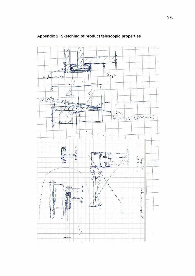
lems was easier. (Appendices 1, 2, 3)
Conceptual drawings made were compared with each other. After visual studies and
discussion, the best and most suitable idea was started to work on.
Before the construction of prototype could have been started, the idea was to be
sketched with 3D tooling program. 3D designing program used was DS SolidWorks
2014.
3.3 Material selection
When selecting materials for the structure, the practical and easy usage for the product
has to be considered. Final weight for product was desired to be as small as possible,
value limited by the lifter was to be taken into account.
Main wall material, for the previous version was transparent PC sheet. The PC sheet
was chosen due to its easy use and fairly good properties. Thickness for PC sheet was
decided to be 10mm. This would ensure the durability of the construction against
formed negative pressure, and minor strains from environment while transport and at
actual use.
Aluminium L- profile was used on the seams of the PC sheet. Industrial glue was se-
lected as addition for strengthening the seam. Glue worked also as a seal for the struc-
ture.
In order to obtain telescopic behaviour for the product, practical solution was found to
be two C-profiles sliding in each other. For its corrosive protective properties AISI 304
stainless steel was chosen the C-profile material. The material will allow various disin-
fectants to be used.

11
A drywall lifter was used as a base for the construction. The drywall lift used, was cho-
sen from company called ABC- Kärry Oy. Maximum load for this specified model is 35
kg, and the lifter material was also AISI 314 stainless steel. Surface of the lifter could
be used as the strongest part for the frame. As for being most expensive single part for
the product, different type of drywall lifters were compared and studied. The best suita-
ble lifter was chosen based on its price, properties and formability.
3.3.1 Material suppliers
Most of the materials needed for constructing the prototype could be found from com-
pany’s warehouse. None the less some material had to be ordered from different com-
panies. Biggest and the main supplier for these materials is ETRA Oy. Other suppliers
are such companies as WÜRTH Oy, ACB- Kärry Oy and LVI-Dahl Oy.
3.4 Design progression
Progression for designing the prototype of the Lifa Secure Box was begun by making
3D sketch. Once the preliminary model was done, the construction of the prototype
itself could have been started. Because the processed prototype was wanted to be as
close production version as possible, the best way for making prototype that works as
wanted, was found to be constructing product from first drawings. The 3D model and
drawings are easy to change once the need for improvements is identified.

12
3.5 Working on prototype
The first couple of weeks were spent by thinking and sketching different solutions for
making the parts slide without too much friction or constraints. After the first draft was
made the base material for the frame was decided to be AISI 304 C-profile. The two
different size C-profiles allow telescopic behaviour for the final product. Profiles were
planned to slide on each other and excess friction would be taken off by using Vaseline
or other appropriate lubricant. All materials for Lifa Secure Box was chosen by taking
into account the weight restrictions brought by handling.
The main material for the secure Box was polycarbonate plate, which is used particu-
larly in greenhouse solutions. In the first prototype made by Lifa Air, the material prop-
erties were proven to be sufficiently strong enough for the suction made inside the box.
The Secure Box will be used with Lifa HC1100 which will give 750 pa (3.01 InH2O)
negative pressure inside the box.
Week after the construction started to become in designed form. In this stage the
weight of the product was approximately 35 kg, which was slightly more than planned.
Secure Box itself was meant to be attached on drywall lifter which can carry 35 kg’s in
maximum. Drywall lifter was modified to have the size that won’t restrict the movability.
At this stage the weight of Secure Box laid on the top limit for the lifter, consequently
modifications were necessary.
Next step was to plan the weight reductions. Best way for reducing weight was to re-
move unnecessary components from the product and change some material for lighter
option if available. Other significant defects noticed at this stage were the dimensions
of the Secure Box. Width of the product was found to be 1- 2 cm too wide. This would
cause problems with fitting the product through “normal” 80 cm door. However, it was
observed that the current width wouldn’t be a problem in hospital environment. As final
decision for these noted problems- after first constructed version, was to rebuild up-
graded version. This would be closer to the actual production version. Prior to any
permanent changes for this version all potential errors and defects were considered
carefully through.

13
On the following week all missing components, including drywall lifter, rails for sliding
parts and sealing materials arrived. The first decision made regarding to the framework
of the Secure Box was to integrate the base of the drywall lifter in it. The base of dry-
wall lifter would also strengthen the structure, meaning that most steel frame supports
could be taken off. This would also reduce the weight of the final product. The dimen-
sions for new version of the Secure Box would make the product easier to transport
between job sites. Determined dimensions for updated prototype were 70 cm in width
and minimum height of 200 cm. With these dimensions the product is easy to move in
elevators and through doors. The quantity of C-profiles was dropped to half. By mak-
ing this modification the expected weight drop would be at least 5 kg.
All components and material from previous version will be reused to keep the expenses
in minimum. Generally the revision of first prototype will consider weight and dimension
improvements and will be closer to the production version.
Figure 5. 3D model from final version of prototype (Lifa Air Ltd, 2014)

14
4 Product testing
The operation of the prototype was tested against any leaks. The test environment was
chosen in a way that stability of conditions could have been ensured. For increasing
particle amount, fogging machine was placed inside the Secure Box. Machine itself
was operated from a distance with remote control.
Testing was carried out in five stages. All five stages included different types of filtration
for negative pressured air. Measurements were performed three times per stage to
ensure that errors would be at minimum.
Stage 1: Normal conditions + HC1100 + Lifa 3G filter
Stage 2: Applying fog + HC1100 + Lifa 3G filter
Stage 3: Applying fog + HC1100 + Lifa 3G filter + G4 pre filter
Stage 4: Applying fog + HC1100 + G4 pre filter + HEPA filter
Stage 5: Applying fog + HC1100 + G4 pre filter + HEPA filter + F7 bag filter for
exhaust air
Figure below shows filtration classes according to standard EN 779:2012
Figure 6. Classification of air filters (www.Camfil.co.uk, 2014)

15
4.1 Equipment used
Equipment used for testing:
Secure Box + HC1100 + accessories (figure 7)
ARTI HHPC – 6, airborne particle counter (figure 8)
ELECTRO GEN 2000 fogging machine (figure 9)
Flexible hose from Secure Box to HC1100 (figure 7)
Figure 7. The final product in compact pack
Figure 8. The particle counter used for testing
Figure 9. Picture of fogging machine used for raising amount of the particles inside Secure Box.

16
4.2 Testing
First the fogging machine was to be placed inside the Secure Box and 3G filter inside
negative pressure unit. Because of its weight, the fogging machine had to be placed in
middle of the box (figure 10).
Figure 10. Placement of Electro gen fogging machine and HC1100 with 3G filter
Next the negative pressure unit was to be started. Before taking any readings it was
important to wait in minimum two minutes until the unit worked in its optimum range.
Once the optimum working range was reached, it was possible to take readings. When
adding filtration between stages, the negative air unit had to be turned off.
Figure 11. On final stage the F7 class exhaust filter was added to negative pressure unit.

17
4.3 Taking readings
Readings were taken with ARTI particle counter. All values were written up to following
tables 1-5. Time gap between each measurement change was 15 minutes. In this time
the particle amount drops to match the readings before testing. At the end of each sec-
tion is presented a brief explanation which explains the result of the particle counter.
The particle counter gave readings within +/- 10 % accuracy.
Table 1. Readings from stage 1. See listing from chapter 4.
Particle size Quantity / liter Other information
Test 1. Test 2. Test 3. 3 tests in row
0.3 µm 8642 8567 8649
0.5 µm 1474 1428 1487 Humidity 27 %
0.7 µm 506 469 498 Temperature: 24 ºC
1.0 µm 200 196 191 Quantities in 1.0 L of air
2.0 µm 56 56 45
5.0 µm 1 5 1
Table 1 shows the figures of particle counts at normal conditions. In other words no
extra fog had been added inside Secure Box. Readings show that IAQ at test area is
very good, even better than it was expected. This will facilitate to see the difference
between all the tests done. The reading for normal office room air is typically at both
sides of 30.000 particles sized of 0.3 µm in Scandinavia. (Haapalainen, K. 2014)

18
Table 2. Readings from stage 2. See listing from chapter 4.
Particle size Quantity / liter Other information
Test 1. Test 2. Test 3. 3 min between tests
0.3 µm 38509 19973 16106
0.5 µm 5624 2924 2452 Humidity 25 %
0.7 µm 1366 791 674 Temperature: 25 ºC
1.0 µm 443 321 221 Quantities in 1.0 L of air
2.0 µm 84 87 66
5.0 µm 7 5 4
Table 2 shows readings after fog was applied. When comparing table two for the start-
ing conditions, it is possible to see how the amount of particles is increased dramatical-
ly. At this stage the vacuum unit was using only Lifa 3G filtration. The reason for such
high particle count was found to be too high face velocity for this type of filter. Because
of the properties of the liquid vaporized and too high airflow, 3G filter didn’t have time to
process all particles going through. It was noticed that particle quantity dropped almost
at the normal level after 10 minutes.
Table 3. Readings from stage 3. See listing from chapter 4.
Particle size Quantity / liter Other information
Test 1. Test 2. Test 3. 3 tests in row
0.3 µm 12678 12765 12327
0.5 µm 2175 2075 2004 Humidity 25 %
0.7 µm 765 678 639 Temperature: 25 ºC
1.0 µm 395 333 313 Quantities in 1.0 L of air
2.0 µm 207 147 121
5.0 µm 38 21 11
On stage 3 the negative pressure unit was fitted with Lifa 3G filter, and as addition G4
pre filter was fitted inside the suction hose / duct in front of the negative air unit. All test
results were taken in a row and approximated time spent for this stage was 15 minutes
in. The results show that additional G4 pre filter boosted 30 % of the efficiency for 3G
filter by giving the maximum amount of 0.3 µm particles approximately 1/3rd, from pre-
vious stage.

19
Table 4. Readings from stage 4. See listing from chapter 4.
Particle size Quantity / liter Room conditions
Test 1. Test 2. Test 3. 3 tests in row
0.3 µm 6643 6505 5722
0.5 µm 1289 1326 1149 Humidity 25 %
0.7 µm 539 548 484 Temperature: 24 ºC
1.0 µm 317 313 272 Quantities in 1.0 L of air
2.0 µm 159 149 117
5.0 µm 24 9 12
Stage 4 testing was performed by changing HEPA filter in to negative pressure unit.
Tests show that HEPA filter is actually making the room air quality better, while nega-
tive pressure unit is powered on. This stage shows also what difference it makes once
filtration is improved.
Table 5. Readings from stage 5. See listing from chapter 4.
Particle size Quantity / liter Room conditions
Test 1. Test 2. Test 3. 3 tests in row
0.3 µm 6025 5883 5723
0.5 µm 1129 1132 1129 Humidity 25 %
0.7 µm 492 493 489 Temperature: 24 ºC
1.0 µm 312 282 275 Quantities in 1.0 L of air
2.0 µm 121 102 94
5.0 µm 23 12 5
On this stage there was F7 classification bag filter added to block the rest of particles
that went through HEPA filter. After that, the filtration combination is G4 pre filter,
HEPA filter and F7 bag filter. The bag filter would also block the airflow from blowing
dust and particles from floor to the air. Tests also showed that small improvements
were gained by adding filtration for exhaust air. This filtration method would increase
the quality of indoor air on area where cleaning process is held on.

20
5 Final evaluation and conclusions
This research for IAQ and especially how it has an direct effect on the spread of infec-
tions, with the data presented in this report, it can be concluded that the need for easier
and faster ways for cleaning chilled beams and convectors needs to be found. It has
been proved that the developed Lifa Air Ltd method reduces time spent for cleaning
these beams by removing unnecessary work steps. Method will improve working condi-
tions on the processed area too.
From the previous research done by Lifa Air and VTT it can be seen that Secure Box
method gave same results as old-established way, leaving as the main differentiating
and beneficial factor to be fast way to clean ventilation equipment. With the new design
the product fits easily inside the normal sized van. This way Secure Box method can
save great amount of money and time from companies operating on sanitation busi-
ness. The method would also make cleaning thoroughly possible more often than it has
been before.
Testing in chapter 4 was done mainly to prove that the construction does not have any
leaks and sealing is sufficient. As the test results indicate the constructed version of
Secure Box don’t have any leakage and the negative pressure inside the box is suffi-
cient for controlling the particle amount inside the box. Test results show that filtration
and combination of different filters have an influence on particle amount on area pro-
cessed.
The project was successful. Project goals were achieved and the prototype meets the
requirements set by the company. In addition the project worked as a learning process
and will work as a base for future projects. The method how this project was carried
out, allowed small changes to be done throughout the process and defects of product
could be seen easily.

21
6 Bibliography
Interviews
Haapalainen, Kimmo. Marketing Director, Oy Lifa Air Ltd: Concept of Lifa Air Secure Box method, Helsinki 31.10.2013 Näsälä, Pauli. Warehouse Manager, Oy Lifa Air Ltd: General information for cleaning process, Helsinki 20.02.2014
Literature
Holopainen R, Kähkönen E, Salmi K, Hellgren U-M, Hintikka E-L, Reijula K. Cleanign of ventilation system at hospital ward. Työterveyslaitos. Helsinki Finland 2011.
Haapalainen K. High tech hospital project: disinfecting and cleaning of chilled beams. Oy Lifa Air Ltd. Helsinki Finland 2012.
RakMK D2. Building indoor air quality and ventilation. Instructions and regulations 2012. Helsinki Finland 2012. Available at: http://www.ym.fi/fi-FI/Maankaytto_ja_rakentaminen/Lainsaadanto_ja_ohjeet/Rakentamismaarayskokoelma (30.03.2014)
Pelastuslaki 29.04.2011/379. Finnish rescue Act available at: www.finlex.fi/data/normit/1917-c1.pdf (30.03.2014)
EN 779:2012. Classification of air filters. European committee for standardization 2012.

1 (8)
Appendices
Appendix 1: Sketching method for sliding profiles
Appendix 2: Sketching of product telescopic properties
Appendix 3: Sketching improvements during construction
Appendix 4: Preliminary 1 3D design from construction
Appendix 5: Decided drywall lift
Appendix 6: Assembled product drawing
Appendix 7: Detailed C-profile drawing

2 (8)
Appendix 1: Sketching method for sliding profiles
3 (8)
Appendix 2: Sketching of product telescopic properties

4 (8)
Appendix 3: Sketching improvements during construction

5 (8)
Appendix 4: Preliminary 1 3D design from construction

6 (8)
Appendix 5: Decided drywall lift
7 (8)
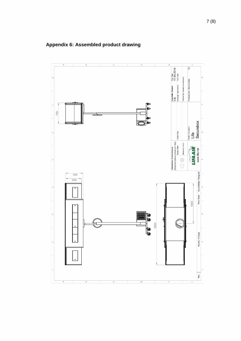
Appendix 6: Assembled product drawing

8 (8)
Appendix 7: Detailed C-profile drawing