lifting and lashing systems lifting, lashing, convey-ing, tire protection as well as snow and...
TRANSCRIPT

Edition 17
LIFTING AND LASHING SYSTEMS– Special Grade 10 –
LIFTING MEANS

2
BG and TÜV approved!
*BG = German EmployersLiability AssuranceAssociation.
8S 10 12
The passion of chain manufacturing!
The round steel chain linkproduction in Unterkochenhas been running for about130 years. Producing chainsfor lifting, lashing, convey-ing, tire protection as wellas snow and off-road chains.
Our headquarters and ma-nufacturing plant is one ofthe most modern chain pro-ducing companies worldwide.
Developed from a smallchain forging company bythe river Kocher, the RUDgroup has stood to the testof time to become a globalplayer with approximately800 motivated employees,subsidiaries and sales repre-sentatives around the world.
Almost 500 national andinternational protectiveclauses are the evidence forour progress.
The well established brandname RUD stands for quali-ty, technical innovation andknow how. Continuous re-search and development hasenabled us not only to pro-duce products meeting thehighest expectations but alsowith consistent quality stan-dards. Experience, diligence,ambition and passion are thevirtues we manifest in orderto remain favourite for ourcustomers. With the abovevirtues in mind, RUD hassuccessfuly entered a newcentury with the trust andsatisfaction of our customersas our prime objective forthe future.What are tomorrow`s con-cepts? This is one of thequestions which RUD is try-ing to address while facingthe challenge of consistentlyproviding the best solutionsto our customers.
Innovation and quality takefirst priority at RUD. We arealways leading in decisivedevelopments.
Examples in the lifting andlashing chains field:
1967: 1. Approval of qualityclass 5, H1-5 by the Berufs-genossenschaft (*EmployersLiability Insurance Associa-tion).
1972: First chain factory togain approval for the qualityclass 8, H1-8 by the BG*Technical Committee ”Steeland Metal“.
The first idea of a mecanosystem from RUD – fool-proof connection of the cor-rect chains and components,as well as suspension links.This idea became the stan-dard at Ruhrkohle RAG (coalboard mining).
1981: The first series of lif-ting points type RBS andRBG with a safety factor 4:1in any direction.
1992: First chain factory toobtain certification for theirquality assurance system acc.to DIN/ISO 9001.
1994: First chain factory toobtain approval of the BG*for their VIP-special qualitywith up to 50 % higher WLLthan Grade 8.
2002: The first universal lif-ting point – called PPS.
2006: First manufacturerwho received the “Type Exa-mination Certificate” fromthe Inspection and Certifica-tion authority PZNM of theTechnical Commitee MO(*Employers Liability Insu-rance Association = BG), forVIP-round steel chains accor-ding to PAS 1061 (PublicityAvailable Specificationaccording to the StandardDIN EN 818 Grade 10).As the First H1-10!
2007: RUD receives as thefirst chain manufacturer the approval for Grade 12(D1-12) from the BG.World premiere of thestrongest lifting chain ICE(Grade 12). Innovation leapin chain technology.Always one chain diameterthinner.
50 80
®
LIFTING MEANS

3
RUD Company Profile/Contents Page 2/3
– Benefits of the RUD-VIP system/applic. examples 4/5
– Assembly-fool proof/advantages 6/7
– Round steel link chain/WLL charts 8/9
– Masterlinks & Special Masterlinks1 leg 10/11
– Masterlinks & Special Masterlinks 2 leg 12/13
– Masterlinks & Special Masterlinks 3/4 leg 14/15
– Cobra hook – Eye hook – Foundry hook 16/17
– Swivel adapter for hoists/Bale hook VIP clevis self locking hook/VIP Grab hook 18/19
– Multi shortening claw 20/21
– Clevis shackle/Shackle/Isolating plate 22/23
– Rhombic link/Container hook Combi lock/Plug-in connector 24/25
– Balancer/Swivel/VRG-Connector 26/27
– Control link/Mini mecano system 28/29
– Spreader bar fixed/Spreader bar adjustable/Edge protection 30/31
– Examples for assembled slings/Spec. applications 32/33
– WLL chart RUD lifting and lashing point 34/35bolt on
– WLL chart RUD lifting and lashing pointsweld on 36/37
– Lashing systems/Load systems securing 38/39
– Inspection/Service/Regular maintenance 40/41
– CD ROM/General information 42/43
RUD industrial chains product groups 44
®
®
®
®
®
®
®
®
®
®
®
®
®
®
®
®
®
®
®
®
CONTENTS

4
lDespite having the same chain diameter, an up to 30 % increase in the WLL in comparison to thehitherto highest quality class 8.
l Chain dimensions from 4 to 22 mm. WLL from 0.6 t to 20 t in single leg and up to 56 t in a 4-legconfiguration with a balancer.
lDistinctive fluorescent pink powder coating and clear "VIP" stamp on every chain link and compo-nent. Distinctive in comparison to other quality classes. Surface quality is comparable to a zinc platedsurface.
lChain diameters 16, 20 and 22 mm in VIP special quality replace the 18, 22 and 26 mm chain diame-ters of quality grade 8. Smaller chain sizes, hence a considerable reduction of weight which facilitates easy handling.
lMultifunctional WLL identification tag: Owing to it`s special patented shape, it facilitates simple inspection of the three wear criteria for sling chains (diameter, elongation of pitch and overload). The inspection data can be documented on the tag.
lHeat indicator:The pink powder coating changes its colour withtemperatures exceeding 200°C. Chain shouldnot be used after being subject to temperaturesexceeding 400°C. At this temperature the VIPcolour changes to a deep black with small bubbles, clearly indicating that it has been over-heated.
lMaster link collection for every crane hook:The chain connecting link VRG is attached to the corresponding master link in a permanent butflexible way. The fool – proof clevis connection allways ensures that only the correct chain diametercan be fitted. The collection of master links range from the smallest VBK size for the high tensilehoist hooks up to crane hook No. 50 with Bi = 250 mm in 1 to 4 leg assembly versions.
lThe patented multi shortening claw can be fitted on the chain leg at any required position. Noadditional chain and coupling parts are required. The robust safety bolt with a spring prevents unintentional hooking out of the chain in both loaded and unloaded conditions. Ideal chain link shaped pocket support, thus no reduction in the WLL.
lVIP Cobra hook:The compact design of the VIP Cobra hook with no protruding hook tip is far superior and saferthan the common clevis sling hook. Supplied complete with a forged and tempered safety latchthat locks into the hook tip protects against lateral bending. The safety latch is supported by a triplecoiled double leg. The enlarged hook tip prevents misuse. Wear edges on both sides of the hookprotect against abrasion of the chain when hauling the chain assemblies. Gauge marks on the hookenable easy inspection for the elongation of the width of the hook opening.
lVIP automatic clevis hook:Extremely robust design. The hook locks automatically when lifting the load and can only beopened by activating the protected unlocking lever at the back of the hook. No protruding hooktip. Large mouth width size F.
lVIP shortening hook: According to pr. EN1677-7:With no reduction of WLL and a thickened hook tip to avoid misuse e.g. incorrect fitting of thechain. Ideal chain support facilitated by the calibrated lugs. The U-bend insertion slot protectsagainst accidental chain disengangement.
lWorld wide unique: The VIP Mecano System with the 4 mm chain.
VIP-proven since 1994
in the hardest applications!
225 °C 250 °C 275 °C 300 °C 320 °C 350 °C 375 °C 400 °C
VIP SLING CHAINS IN RUD SPECIAL QUALITY CLASS 10
Sub
ject
to
tec
hn
ical
alt
ern
atio
ns!
®
LIFTING MEANS
Mecano System”in miniature”
4 mm chain andcomponents!
®
-

5
Applicationexamples – VIP –
®
®
use
VIP-Quality –“Made in Germany!”
Sub
ject
to
tec
hn
ical
alt
ern
atio
ns!

VIP Stamping – on every chainlinkVIP-stamped chains are manu-factured with smaller toleran-ces in the inner width (size W1)and are coated with the fluores-cent colour pink. In connectionwith the VIP stamped, pinkcoloured components, whosespecial clevis design has beenperfectly harmonised, a distinc-tive chain connection is real-ised.
10 or 8 SThe approval of RUD´s specialquality VIP by the BG* is docu-mented in short chain linkintervals with the following:H1 refering to the manufactur-er`s number i.e 1 = RUD and 8 S or 10 meaning Grade 10.
Verification of qualityAt regular intervals, the chainsare stamped with a serial andbatch number. This identifica-tion ensures a continuousrecord tracking of the manu-facturing and proof load dataeven after a period of 10 years.After all we stick to our VIPquality.
Patented heat indicator In high temperature environ-ments the special fluorescentpink powder coating perma-nently changes its colour.Above 400°C the colour chan-ges permanently to black. Ifthis happens the chain assem-bly should be taken out of ser-vice (refer to page 7).The geometric construction andtolerances of the VIP chains arealigned to a higher quality class.On request, Corrud DS, a 20times more red rust resistantcomponent than zinc plating,can be supplied.
VIP Grade 10A consequential enhancementof the RUD – Mecano systemwith quality grade 8, which hasstood to the test of time forover 30 years. V – distinguished,I – in, P – pink.
Using the patented VIP identifi-cation tag, the chain can easilybe inspected for wear andpitch elongation. Please referto pages 8 and 40.
BG* = Employers Liability Insurance Association.
TheThe highly qualitative VIPchains and components areprovided with a duplex surfaceprotection. This comprises oftwo processes i.e: Pre-treatmentand pink powder coating. Dueto this two process procedure,a relatively better surface pro-tection is achieved in compari-son to zinc plating.
The highly dynamic VIP-Mecano system and chainsachieves a dynamic strengthhigher than the standardvalues. Tested with over 20,000load cycles and with a factorratio of 1.5 of their actual WLL.
An up to 30 % increase in theWLL in comparison to qualityclass 8Material CrNiMo alloy steel,specially tempered, hightoughness. Minimum breakingelongation � 25 % in naturalblack, � 20 % in pink coated.
Less sensitive to notching andhydrogen embrittlement thanquality class 8. Bending testsacc. standard DIN EN 818-2,bending min f = 0.8 x d is by farexceeded. Ratio of WLL : proofload : breaking load is given by1 : 2.5 : 4.Owing to a special heat treat-ment procedure developed byRUD, the highly dynamic RUD –VIP-chains are less sensitive tomechanical abrasion anddamages. Hence an increasedlife expectancy is achieved.
Quality class 8 chains whosenominal diameter exceeds 18 mm can be substituted by aone size less nominal diameter chains in VIP quality. Giving the same WLL despite a 50 % weight reduction.
YOUR BENEFITS…
Ø 1610 t
Ø 1810 t
Grade 8
6
Sub
ject
to
tec
hn
ical
alt
ern
atio
ns!
VIP
spec
ial q
ualit
y
quality
clas
s 8
60 kN
45 kN
up to 30 % increased WLL
quality class 8
Example: Ø 6 Breaking elongation
> 20 %in surface treatedcondition
15 kN
11 kN
RUD chains and componentsare in accordance with DIN EN818 and 1677 with a dynamicloading of more than 20,000load cycles.The BG* recommends: At highdynamic applications with highload cycles (permanent opera-tion), the WLL must be redu-ced, e.g. by using a largerchain diameter.
VIP
VIP

The German Employers Liabi-lity Assurance Associationrequires:
1.) Chain slings of Grade 10must not be used in combi-nation with chains and com-ponents from different manu-facturers.2.) Components which arerecognized as Grade 10, mustnot be mixed with Grade 8sling components.
The proven clevis connectionsystem has been furtherenhanced with the new VIPrange. With it`s dimensionaladjustments and colour (VIPchains and components inpink) arrangement of thechains and the components, afool-proof assembly is assured.
Clevis dimension ”X“ avoidsthe connection of a larger VIPchain. VIP chains are manufac-tured with tighter tolerances inthe inner width (size W1). Theconnection bolt diameter ”sizeY“ avoids the connection ofthe next smaller VIP chain size.
Result:Only chains and componentswith the same WLL are distinc-tively assembled together.
Slot of the tensioning sleevemust be visible facing to thefront! The tensioning sleevemust be used only once.
The special fluorescent VIPpowder coating permanentlyshows the temperature towhich the VIP chain has beenexposed.
Operated in the prohibitedtemperature ranges i.e. above400°C, the pink colourationturns black with bubles on thesurface. Replace the VIP chainsor return them to the supplierfor repair.
Applicationexamples ofthe versatileVIP system.
Assembly
VIP heat indication Europeanpatent EP 677681
VIP-Fool-proof Mecanoassembly
FOOL-PROOF »IN PINK«
225 °C 250 °C 275 °C 300 °C 320 °C 350 °C 375 °C 400 °C
Patented: The VG-bolt of the nextsmaller size drops out.
Y
W1
X
FOOL-PROOF »IN STAMPING«
FOOL-PROOF »IN PINK+STAMPING«
7
use
+point
Sub
ject
to
tec
hn
ical
alt
ern
atio
ns!
®
LIFTING MEANS
Attention:
VIP chains 8S or 10 mustonly be connected with VIPcomponents 8S or 10. Follow RUD operating manualand user instructions! Use only original VIP spareparts.

8
Size din mm Ø 4 6 8 10 13 16 20 22
Pitch P 12 18 24 30 39 48 60 66in mm
inside, width 5.2 7.8 10.4 13 17 21 26 28.6W1 bi min. mm
WLL 0.63 1.5 2.5 4.0 6.7 10 16 20in t
Proof load 15.7 37.5 62.5 100 166 250 395 500MPF min. kN
Breaking load 25 60 100 160 265 400 630 800BF min. kN
Weight 0.36 0.85 1.5 2.4 4.0 6.0 9.5 12.3kg/m
Surface: Duplex protection = pre-treatment + pink powder coating
Order no: 7984399 7100477 7100478 7100479 7100480 7100481 7983689 7100482
Surface: Corrud-DS-black
Order no: 7987349 7987591 7986226
Minimal ultimate elongation: natural black � 25 %, Pink � 20 %Stamped: VIP identification stamped in every chain link, manufacturing number and the BG approval stamp H1
VIP roundsteel link
chainGrade 10
VIP identifi-cation tag
with an integrated
chain testinggauge
EP 610611
Testing wear of nominal diameter
Testing for plastic elongationcaused by overload
Testing for pitch elongationcaused by wear of nominal diameter
Wear test of the nominaldiameter with indicationof the minimal diameter (–10 %)
VIP WLL (single-leg)
Front Reverse
Chain pitch gauge testing forpitch elongation caused bywear of nominal diameter.
Assembly – number oflegs (multiple-leg)
Chain diameter
Engravingthe next testdate
Space foridentifica-tion num-ber
Testing of plasticelongation causedby overloading.
VIP WLL with indica-tion of inclinationangle
PW
1
d
nächste Prüfung: 05/06/07/08/09
Sub
ject
to
tec
hn
ical
alt
ern
atio
ns!
®
LIFTING MEANS

Endless chain Choke hitch
single double single double
0–45° > 45–60° 0–45° > 45–60° 0° 0–45° > 45–60°Load factor 1.1 0.8 1.7 1.2 0.8 1.1 0.8
Ø 4 0.69 0.5 1.1 0.75 0.5 0.69 0.56 1.65 1.2 2.55 1.8 1.2 1.65 1.28 2.75 2 4.25 3 2 2.75 2
10 4.4 3.2 6.8 4.8 3.2 4.4 3.213 7.5 5.3 11.2 8 5.3 7.5 5.316 11 8 17 12 8 11 820 17.6 12.8 27.2 19.2 12.8 17.6 12.822 22 16 34 24 16 22 16
In case of unsymmetrical loading, the load factorsmust be modified as follows:
When using sling chains at temperatures beyond 200°C (refer to page 7), the permissible WLL has to be reduced.
Temperature Working load in % at chain temperature of:°C – 40° up to + 200 °C above 200° – 300 °C above 300° – 380 °C
100 % 90 % 60 %
1-leg 2-leg 3- and 4-leg endless
Inclination-� � 0° 0–45° > 45–60° 0–45° > 45–60° –Load factor 1 1.4 1 2.1 1.5 1.6
Ø 4 0.63 0.88 0.63 1.32 0.95 16 1.5 2.1 1.5 3.15 2.25 2.48 2.5 3.5 2.5 5.25 3.75 4
10 4.0 5.6 4.0 8.4 6.0 6.413 6.7 9.5 6.7 14 10 10.616 10 14 10 21 15 1620 16 22.4 16 33.6 24 25.622 20 28 20 42* 30 32
In case of unsymmetrical loading, the load factorsmust be reduced by 50 %.
9
VIP Grade 10WLL in tonnesof single and multi-ple leg chain slingswith differentangles of inclina-tion and symmetri-cal loading of thelegs.
In case of chokehitch applications,reduce WLL by 20 %.
A reduction of 20 % for the choke hitch and bundling (sharp edge) is already within the calculation.
Please refer to RUD Multi master with angle measuring device and CD-ROM* in connection with balancer up to 56 t (see page 26).
Nominal sizeof sling chainin mm
endlesschain sling in chokehitch
Nominal sizeof sling chainin mm
Ø 4 mmseepage29
use
+point
Sub
ject
to
tec
hn
ical
alt
ern
atio
ns!
®
LIFTING MEANS

10
VIP Masterlink
for single legVBK1
for smallerload hooks
VIP Masterlink
for single legVAK 1
for standard
crane hookse.g. DIN
15401
VBK 1 master link with an in all multi-directionalmovable welded VRG connector. Thus ensuringthat the correct chain diameter and number oflegs can be connected. Complete identification tagwith an integrated testing gauge. Connecting boltand tensioning sleeve are pre-assembled.
Can also be suppliedas end link (VB-1) without VIP identifi-cation tag.
The size corresponds with that of connecting link type B according to DIN 5688. Sufficient for attachment in small load hooks on hoisting devices.
Chain WLL t Type A B C T kg/pc. Ref. No.6 1.5 VBK 1 – 6 (VB 1 – 6) 13 25 54 82 0.5 71 00 675 (7100 220)8 2.5 VBK 1 – 8 (VB 1 – 8) 16 34 70 107 0.7 71 00 676 (7100 221)
10 4 VBK 1 – 10 (VB 1 – 10) 18 40 85 131 1.1 71 00 677 (7100 222)13 6.7 VBK 1 – 13 (VB 1 – 13) 22 50 115 174 2.0 71 00 678 (7100 223)16* 10 VBK 1 – 16 (VB 1 – 16) 26 65 140 211 3.3 71 00 679 (7100 224)20* 16 VBK 1 – 20 (VB 1 – 20) 32 75 170 264 7.6 71 04 092 (7104 093)22* 20 VBK 1 – 22 (VB 1 – 22) 36 110 200 294 9.0 71 00 680 (7102 060)
Chain WLL t Type A B C T kg/pc. Ref.No.6 1.5 VAK 1 – 6 (VA 1 – 6) 13 60 110 138 0.6 71 00 681 (7100 237)8 2.5 VAK 1 – 8 (VA 1 – 8) 16 60 110 147 0.9 71 00 682 (7100 238)
10 4 VAK 1 – 10 (VA 1 – 10) 18 75 135 181 1.4 71 00 683 (7100 239)13 6.7 VAK 1 – 13 (VA 1 – 13) 22 90 160 218 2.4 71 00 684 (7100 240)16* 10 VAK 1 – 16 (VA 1 – 16) 26 100 180 250 3.7 71 00 685 (7100 241)20* 16 VAK 1 – 20 (VA 1 – 20) 40 180 340 434 14.7 71 04 089 (7104 090)22* 20 VAK 1 – 22 (VA 1 – 22) 45 180 340 434 16.5 71 00 686 (7102 092)
VBK 1 master link with an in all multi-directionalmovable welded VRG connector. Thus ensuringthat the correct chain diameter and number oflegs can be connected. Complete identification tagwith an integrated testing gauge. Connecting boltand tensioning sleeve are pre-assembled.
The size corresponds with that of connecting linktype A according to DIN 5688.
Master link VAK1 can be used for crane hooks upto No. DIN 15401. – standard size hooks
Size: 6 – No. 2.5 8 – No. 2.510 – No. 5 13 – No. 616 – No. 8 20 – No. 2522 – No. 25
Can also be supplied as end link (VA-1) withoutidentification tag.
B A
C
T
B A
C
T
*Attention: Master link size 16/20/22 with a special identification tag (refer to page 14). A testing gauge will be additionally supplied with the master link sizes 16/20/22 Su
bje
ct t
o t
ech
nic
al a
lter
nat
ion
s!
®
LIFTING MEANS

11
VSAK1 master link is suppliedcomplete with a welded VRGconnector. Therefore only the correct chain diameter and num-ber of legs can be connected. Theidentification tag with an inte-grated testing gauge is alreadyattached.
Connecting bolt and tensioningsleeve are pre-assembled.
Owing to a larger gradation ofthe inner width "B" of the VSAK,improper use (BGR 500) is almosteliminated and wear of the cranehook is minimised. Additionalconnective components for oversize hooks are not necessary.
Forged Special-Link (in pink) forsmall load hooks, extreme light-weight construction – centre flattening respective to the cor-responding chain diameter.
Fits to the Universal-Swivel-PowerPoint from page 27 or tothe Lifting Point PowerPoint-B.
Additionally pay attention to thecorrect WLL assignment whileassembling.
VIP specialmaster link 1-leg VSAK 1
VIP specialmaster link 1-legPP-X-B– lightweightconstruction –
Chain WLL t Type A B C T kg/pc. Ref. No.6 1.5 VSAK 1 – 6/140 18 140 260 342 1.7 71 00 6878 2.5 VSAK 1 – 8/140 22 140 260 367 3.1 71 00 688
10 4 VSAK 1 – 10/140 26 140 260 391 4.4 71 00 68913 6.7 VSAK 1 – 13/140 32 140 260 433 7.6 71 00 69016* 10 VSAK 1 – 16/140 32 140 260 471 8.1 71 00 691
Chain WLL t Type A B C T kg/pc. Ref. No.8 2.5 VSAK 1 – 8/190 22 190 350 457 4.0 71 00 692
10 4 VSAK 1 – 10/190 26 190 350 481 6.0 71 00 69313 6.7 VSAK 1 – 13/190 32 190 350 523 9.9 71 00 69416* 10 VSAK 1 – 16/190 36 190 350 560 13.5 71 00 695
Chain WLL t Type A B C T kg/pc. Ref. No.10 4 VSAK 1 – 10/250 36 250 460 590 12 71 00 69613 6.7 VSAK 1 – 13/250 36 250 460 634 13 71 00 69716* 10 VSAK 1 – 16/250 40 250 460 670 14 71 00 69820* 16 VSAK 1 – 20/250 45 250 460 724 25 71 04 10022* 20 VSAK 1 – 22/250 51 250 460 754 33 71 00 699
use
+point
Chain WLL t Type A B C D R1 kg/pc. Ref. No.
4 0.63 PP 0.63t - B 9 35 65 4 15 0.1 79 89 531
6 1.5 PP 1.5t - B 11 35 65 6 15 0.14 85 02 173
8 2.5 PP 2.5t - B 13 40 75 8 18 0.2 85 02 174
10 4 PP 4t - B 16 45 95 10 20 0.32 85 02 175
13 6.7 PP-VIP Ø 13-B 21 60 130 13 25 1.02 85 02 176
16 10 PP-VIP Ø 16-B 24 65 140 16 28 1.4 85 02 177Sub
ject
to
tec
hn
ical
alt
ern
atio
ns!
®
LIFTING MEANS
VSAK – size B = 140 for standard hooks up to. No. 16 DIN 15401VSAK – size B = 190 for standard hooks up to. No. 32 DIN 15401VSAK – size B = 250 for standard hooks up to. No. 50 DIN 15401
B140
190A C
T
B
250B
VBK 2 master link is supplied with two welded VRGconnectors. Therefore only the correct chain dia-meter and number of legs can be connected. Theidentification tag with an integrated testing gaugeis already attached. Connecting bolt and tension-ing sleeve are pre-assembled.
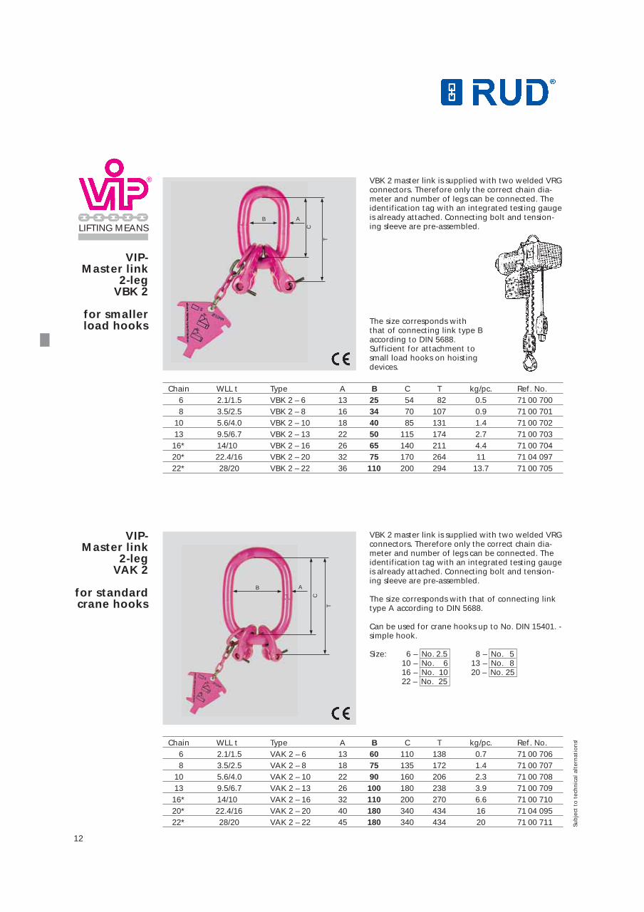
The size corresponds with that of connecting linktype A according to DIN 5688.
Can be used for crane hooks up to No. DIN 15401. -simple hook.
Size: 6 – No. 2.5 8 – No. 510 – No. 6 13 – No. 816 – No. 10 20 – No. 2522 – No. 25
12
VIP-Master link
2-leg VBK 2
for smallerload hooks
VIP-Master link
2-leg VAK 2
for standardcrane hooks
VBK 2 master link is supplied with two welded VRGconnectors. Therefore only the correct chain dia-meter and number of legs can be connected. Theidentification tag with an integrated testing gaugeis already attached. Connecting bolt and tension-ing sleeve are pre-assembled.
The size corresponds with that of connecting link type B according to DIN 5688. Sufficient for attachment to small load hooks on hoisting devices.
Chain WLL t Type A B C T kg/pc. Ref. No.6 2.1/1.5 VBK 2 – 6 13 25 54 82 0.5 71 00 7008 3.5/2.5 VBK 2 – 8 16 34 70 107 0.9 71 00 701
10 5.6/4.0 VBK 2 – 10 18 40 85 131 1.4 71 00 70213 9.5/6.7 VBK 2 – 13 22 50 115 174 2.7 71 00 70316* 14/10 VBK 2 – 16 26 65 140 211 4.4 71 00 70420* 22.4/16 VBK 2 – 20 32 75 170 264 11 71 04 09722* 28/20 VBK 2 – 22 36 110 200 294 13.7 71 00 705
Chain WLL t Type A B C T kg/pc. Ref. No.6 2.1/1.5 VAK 2 – 6 13 60 110 138 0.7 71 00 7068 3.5/2.5 VAK 2 – 8 18 75 135 172 1.4 71 00 707
10 5.6/4.0 VAK 2 – 10 22 90 160 206 2.3 71 00 70813 9.5/6.7 VAK 2 – 13 26 100 180 238 3.9 71 00 70916* 14/10 VAK 2 – 16 32 110 200 270 6.6 71 00 71020* 22.4/16 VAK 2 – 20 40 180 340 434 16 71 04 09522* 28/20 VAK 2 – 22 45 180 340 434 20 71 00 711
B A
C
T
B A
C
T
Sub
ject
to
tec
hn
ical
alt
ern
atio
ns!
®
LIFTING MEANS

13
VSAK 2 master link is suppliedwith two welded VRG connectors.Therefore only the correct chaindiameter and number of legs canbe connected. The identificationtag with an integrated testinggauge is already attached.
Connecting bolt and tensioningsleeve are pre-assembled. VIP-
specialmaster link 2-leg VSAK 2
Owing to a larger gradation of the inner width "B" of the VSAK, improper use (BGR 500) is almost eliminated and wear of the crane hook is minimised. Additional connective components for over sizehooks are not necessary.
VSAK – Size B = 140 for standard hooks up to No. 16 DIN 15401VSAK – Size B = 190 for standard hooks up to No. 32 DIN 15401VSAK – Size B = 250 for standard hooks up to No. 50 DIN 15401
Chain WLL t Type A B C T kg/pc. Ref. No.6 2.1/1.5 VSAK 2 – 6/140 18 140 260 342 2.3 79 94 0708 3.5/2.5 VSAK 2 – 8/140 22 140 260 367 3.5 79 94 071
10 5.6/4.0 VSAK 2 – 10/140 26 140 260 391 5.2 79 94 07213 9.5/6.7 VSAK 2 – 13/140 32 140 260 433 9.2 79 94 07316* 14/10 VSAK 2 – 16/140 32 140 260 471 12.5 79 94 074
Chain WLL t Type A B C T kg/pc. Ref. No.8 3.5/2.5 VSAK 2 – 8/190 22 190 350 457 4.3 79 94 075
10 5.6/4.0 VSAK 2 – 10/190 26 190 350 481 6.5 79 94 07613 9.5/6.7 VSAK 2 – 13/190 32 190 350 523 10.6 79 94 07716* 14/10 VSAK 2 – 16/190 36 190 350 560 15.6 79 94 078
Chain WLL t Type A B C T kg/pc. Ref. No.10 5.6/4.0 VSAK 2 – 10/250 36 250 460 591 12.8 79 94 07913 9.5/6.7 VSAK 2 – 13/250 36 250 460 634 14.9 79 94 08016* 14/10 VSAK 2 – 16/250 40 250 460 671 20.5 79 94 08120* 22.4/16 VSAK 2 – 20/250 45 250 460 724 32.5 79 94 08322* 28/20 VSAK 2 – 22/250 51 250 460 754 43 79 94 084
*Attention: Master link size 16/20/22 with a special identification tag (refer to page 14). A testing gauge will be additionally supplied with the master link sizes 16/20/22
use
+point
Sub
ject
to
tec
hn
ical
alt
ern
atio
ns!
®
LIFTING MEANSB
140190
A C
T
B
250B

VIP-Master link
4-leg VAK 4
VAK 4 leg master link is supplied with four weldedVRG connectors. Therefore only the correct chaindiameter and number of legs can be connected.The identification tag with an integrated testinggauge is already attached. Connecting bolt andtensioning sleeve are pre-assembled.
The size corresponds with that of connecting linktype A and B according to DIN 5688.
Can be used for crane hooks up to No. acc. to DIN 15401.
Size: 6 – No. 5 8 – No. 610 – No. 8 13 – No. 1016 – No. 16 20 – No. 3222 – No. 32
Chain WLL t Type A B C T kg/pc. Ref. No.6 3.1/2.2 VAK 4 – 6 18 75 135 217 1.5 71 00 7428 5.2/3.7 VAK 4 – 8 22 90 160 268 2.8 71 00 743
10 8.4/6.0 VAK 4 – 10 26 100 180 311 4.6 71 00 74413 14/10 VAK 4 – 13 32 110 200 373 8.3 71 00 74516* 21/15 VAK 4 – 16 36 140 260 470 13.7 71 00 74620* 33.6/24 VAK 4 – 20 51 190 350 614 39 71 04 18122* 42/30 VAK 4 – 22 51 190 350 644 42 71 00 747
3 leg master links VAK 3 and VSAK 3 do have the same reference numbers as 4 leg master links. No separate stock exists.
B A
C
T
14
VIP identification tag as *chain testing gauge, for diameters 16 mm/20 mm/22 mmChain Type Ref. No.
16 VKPL-16 71 00 67220 VKPL-20 71 04 04522 VKPL-22 71 01 832
VIP-Spare parts
VKZA
VKPL
80
80
*Comes as separate item with each Masterlink shipment of these sizes.
VIP identification tag for chain diameterDiameter Ref. No.Ø 16 mm/20 mm/22 mm 79 89 739
Sub
ject
to
tec
hn
ical
alt
ern
atio
ns!
®
LIFTING MEANS
*Attention: Master link size 16/20/22 with a special identification tag (refer to page 14). A testing gauge will be additionally supplied with the master link sizes 16/20/22

15
VSAK 4 master link is suppliedwith four welded VRG connec-tors. Therefore only the correctchain diameter and number oflegs can be connected. The iden-tification tag with an integratedtesting gauge is already attached.
Connecting bolt and tensioningsleeve are pre-assembled.
For the respective crane hooksrefer to page 11.
VIP-Specialmaster link 4-leg VSAK 4
VIP-spare parts VKZA
VG/SP
Chain WLL t Type A B C T kg/pc. Ref. No.6 3.1/2.2 VSAK 4 – 6/140 22 140 260 342 3.3 71 00 7488 5.2/3.7 VSAK 4 – 8/140 26 140 260 367 5.0 71 00 749
10 8.4/6.0 VSAK 4 – 10/140 32 140 260 391 7.9 71 00 750
Chain WLL t Type A B C T kg/pc. Ref. No.6 3.1/2.2 VSAK 4 – 6/190 22 190 350 432 3.6 71 00 7518 5.2/3.7 VSAK 4 – 8/190 26 190 350 457 5.5 71 00 752
10 8.4/6.0 VSAK 4 – 10/190 32 190 350 481 9.2 71 00 75313 14/10 VSAK 4 – 13/190 36 190 350 523 13.5 71 00 754
Chain WLL t Type A B C T kg/pc. Ref. No.10 8.4/6.0 VSAK 4 – 10/250 36 250 460 591 14.8 71 00 75513 14/10 VSAK 4 – 13/250 40 250 460 634 20.4 71 00 75616* 21/15 VSAK 4 – 16/250 51 250 460 671 34.5 71 00 75720* 33.6/24 VSAK 4 – 20/250 54 250 460 754 45.5 **79 93 21022* 42/30 VSAK 4 – 22/250 56 250 460 763 53.6 **79 93 211
VIP identification tag with integrated testinggauge.Chain Type Ref. No.
4 VKZA-4 79 87 0546 VKZA-6 71 00 8048 VKZA-8 71 00 805
10 VKZA-10 71 00 80613 VKZA-13 71 00 807
VG bolts with tensioning sleevesChain Type Ref. No.
4 VG-4/retaining pin 4 79 84 300/51 2996 VG-6/retaining pin 6 71 01 594/59 2898 VG-8/retaining pin 8 71 01 595/57 490
10 VG-10/retaining pin 10 71 01 596/59 02113 VG-13/retaining pin 13 71 01 597/59 02216 VG-16/retaining pin 16 71 01 598/59 02320 VG-20/retaining pin 20 71 02 717/59 38622 VG-22/retaining pin 22 71 01 599/59 387
l
Nominal chain size
use
+point
10
**with VVS-U-connection
Sub
ject
to
tec
hn
ical
alt
ern
atio
ns!
®
LIFTING MEANS
*Attention: Master link size 16/20/22 with a special identification tag(refer to page 14). A testing gauge will be additionallysupplied with the master link sizes 16/20/22
B140
190A C
T
B
250B

16
VIP-Cobra hook
with safety latch
VCGH
VIP-Cobra-
eye hook with
safety latchVCÖH
Extremely robust improved version.No protruding hook tip.Forged safety latch engages into the tip of the hook and is thus protected against lateralbending. A triple-coiled, double-leg spring in stainless steel.Thickened tip of the hook prevents misuse.Wearing edges on both sides.
Gauge marks for measuring the width of the hookopening.
Fmax. = Maxi-mum distancebetween thegauge marks.
Chain WLL t Type A B C D F F max. G T kg/pc. Ref. No.6 1.5 VCGH 6 38 22 16 20 25 45 72 76 0.4 71 00 4988 2.5 VCGH 8 50 28 20 28 30 52 95 97 0.9 71 00 499
10 4.0 VCGH 10 60 36 26 36 35 65 118 108 1.5 71 00 50013 6.7 VCGH 13 76 46 30 37 40 73 135 126 2.7 71 00 50116 10.0 VCGH 16 83 56 36 49 48 87 161 152 4.3 71 00 50220 16.0 VCGH 20 112 68 50 69 63 114 218 195 10.0 71 03 38522 20.0 VCGH 22 117 78 50 74 63 114 223 198 11.5 71 01 603
Chain WLL t Type A B C D E F G H T kg/pc. Ref. No.4 0.63 VCÖH 4 18 18 12 13 14 18 52 8 75 0.14 85 02 3236 1.5 VCÖH 6 24 22 16 22 24 25 73 11 98 0.5 85 02 2038 2.5 VCÖH 8 32 28 20 28 31 30 95 13 126 0.8 85 02 142
10 4.0 VCÖH 10 38 36 26 36 39 35 118 17 150 1.6 85 02 14513 6.7 VCÖH 13 48 45 30 37 48 40 135 21 170 2.9 85 02 20416 10 VCÖH 16 63 56 36 49 58 50 161 27 208 4.2 85 02 146
G
A B
C
DT
F
For special wire rope slings, VIP chain slings,PowerPoint combinations or the universal swivel(refer to page 27).Extreme durable, compact design, with pink powder coating.No protruding hook tip.The forged, quenched and tempered safety latch,engages into the hook tip. Therefore protected against lateral bending. Triple coiled, stainless steel double leg spring. Thickened hook tip to avoid improper use. Wear edges on both sides.
Gauge marks for measuring the width of the hookopening.
Fmax. = Distance between thegauge marks,see VCGH dataabove.
NEW!
Sub
ject
to
tec
hn
ical
alt
ern
atio
ns!
®
LIFTING MEANS

17
Safety latchset for VCGH
Consisting of a forged safety latch, a triplecoiled corrosion protected double leg springand a tensioning sleeve. Can be supplied as complete set. Easy installa-tion and removal using only hammer and driftpunch.
Chain Type kg/pc. Ref. No.4 Si-Set VMH-4 0.04 79 87 901 006 Si-Set VCGH-6 0.04 71 00 2998 Si-Set VCGH-8 0.07 71 00 300
10 Si-Set VCGH-10 0.09 71 00 30113 Si-Set VCGH-13 0.15 71 00 30216 Si-Set VCGH-16 0.24 71 00 30320 Si-Set VCGH-20 0.40 71 01 60422 Si-Set VCGH-22 0.40 71 01 604
Use only RUD original spare parts!
VIP-Foundryhook VWH
Considerably larger mouth width than VCGH, butwithout a safety latch.Use only where unintentional unhooking is impossible.
Inappropriate for overhead lifting!When using foundry hooks, special attention mustbe paid and a risk assessment must be carried outbefore using.
Robust cross section (size C/G) is resistant againstincreased lateral forces. Specially designed wearing edges to protect thechain link, compare the dimension "E". Connecting bolt and tensioning sleeve are pre-assembled.
Gauge marks for measuring the width of the hookopening.
Fmax. = Maximum distance between marked points.
Chain WLL t Type A B C D E F F max. G T kg/pc. Ref. No.6 1.5 VWH 6 30 22 18 30 22 50 63 22 87 0.5 71 00 2108 2.5 VWH 8 40 29 26 40 29 64 81 30 115 0.9 71 00 211
10 4.0 VWH 10 46 37 30 50 36 76 96 37 130 1.7 71 00 21213 6.7 VWH 13 51 45 37 64 46 90 115 51 168 3.0 71 00 21316 10.0 VWH 16 64 56 40 75 56 100 129 58 190 5.7 71 00 21420* 16 VWHÖ 20 86 70 65 107 30 127 70 265 13.0 79 88 98522* 20 VWHÖ 22 96 80 71 122 34 136 80 305 19.0 79 88 986
E
D
T
BA
F
CG
*eye type, chain connection with VVS
use
+point
Can also be used asspare part for theRUD GSH 80 hook!Su
bje
ct t
o t
ech
nic
al a
lter
nat
ion
s!
®
LIFTING MEANS

Hoist Swivel
adapter HWA
VIP-Bale hook
VBMH with ball-
bearing swivel
l Supplied complete with ori-ginal Demag ball bearingl Manufactured from high-tempered special steell tested acc. to EN 1677l suitable for single leg snatchblocks and for double leglower blocks l suitable for all RUD clevisMecano components
Application examples:
for Demaghoists
*withVCGH
for Demag-PK-hoistsType WLL Ref. No.
kgHWA 6 PK ( 1) 250 51 287HWA 6 PK ( 2) 500 51 288HWA 8 PK ( 2) 500 51 293HWA 8 PK ( 5) 1000 51 294HWA 10 PK (10) 2000 51 295
The bevelling on the back of the hook simplifiesthe horizontal hook insertion between the bales.The clevis connection enables a direct chain connec-tion and the integrated ball bearing swivel preventsthe chain from automatically spinning.
Suitable only for the transport of bundled bale packages.
Not suitable for choke lifts!
Inappropriate for overhead lifting!
When using bale hooks, special attention must bepaid and a risk assessment must be carried out befo-re using.
Chain WLL t Type A B C T kg/pc. Ref. No.8 2.5 VBMHWA – 8 35 18 61 381 2.5 79 91 47810 4.0 VBMHWA –10 35 18 61 381 2.5 79 89 017
B
CT
A
*withVB-link
*withVVGSCH
*
18
Sub
ject
to
tec
hn
ical
alt
ern
atio
ns!
®
LIFTING MEANS
Clevis connection
for Demag-DK-hoistsType WLL Clevis kg/pc. Ref. No.
t connectionHWA 6 DK 400 DC 1+2 up to 250 kg 0.4 6 0.15 7985570HWA 6 DK 800 DC 5 up to 500 kg 0.8 6 0.30 7985571HWA 8 DK 800 DC 5 up to 500 kg 0.8 8 0.40 7985572HWA 8 DK 1250 DC 10+20 up to 1000 kg 1.25 8 0.55 7985573HWA 10 DK 2500 DC 20* 1000-2000 kg 2.5 10 0.90 7985574HWA 13 DK 5000 5.0 13 1.3 7985575
*only in combination with Demag DK bottom block

VIP-Self-lockinghook VAGH
VIP-shorteninghook VVH
Extremely robust and approved design. Hook automatically locks when lifting the load. Can only be opened by activating the protectedunlocking lever on the back of the hook.No protruding hook tip. Large mouth width size F.Wearing edges > dimension B < on both sides ofthe hook protect the chain against abrasion whenthe assembly is dragged or hauled.Connecting bolt and tensioning sleeve are pre-assembled.Safety latch spare parts available on demand.
lNo reduction of the VIP-WLL.
lThickened hook tip toavoid misuse e.g; in-correct insertion of thechain.
lThe calibrated toothlugs facilitate an opti-mal chain positioning inthe hook.
lThe curved insertionopening prevents thechain from easily fallingout in compliance withpr EN 1677-7.
lConnecting bolt andtensioning sleeve are pre-assembled. Shortening
by meansof VVS
and VVH
Endlesschain bymeansof VVH
Chain WLL t Type A B C D E F T kg/pc. Ref. No.8 2.5 VAGH 8 36 22 25 31 91 43 117 0.35 71 01 500
10 4.0 VAGH 10 44 28 33 36 109 47 140 0.8 71 01 50113 6.7 VAGH 13 58 36 38 44 138 64 169 2.2 71 01 50213 6.7 VMAGH 13 ...for dumpers see page 24
Chain WLL t Type A B C D E F T kg/pc. Ref. No.6 1.5 VVH 6 31 18 20 43 7.5 23 50 0.25 79 88 6588 2.5 VVH 8 38 22 25 54 9.5 33 64 0.35 79 87 319
10 4.0 VVH 10 47 28 31 68 12 42 80 0.8 79 87 32013 6.7 VVH 13 60 36 40 87 15 47 103 2.2 79 87 32116 10.0 VVH 16 75 45 50 108 18.5 57 125 2.9 79 88 669
BA
TD
F
CE
F
B
E
A
T
C
D
VVHVVS max. 60°
VVH
Special designed hook tipto avoid misuse.
Probable misuse!5
19
use
+point
Attention:
New Standard for
shortening ele-
ments pr EN 1677-7!
All RUD shortening
components do
already fulfil these
requirements.
Sub
ject
to
tec
hn
ical
alt
ern
atio
ns!
®
LIFTING MEANS

User advice:Easier application for example ifan endless sling is being used.
After decades of success the RUD shortening clawhas been further enhanced.Fitted on a continuous chain strand at any requiredposition.Fitted permanently on the chain leg at any requi-red position, no additional chain coupling devicesare required. It can either be mounted or easily moved to anyposition along the chain leg. The ideal link shaped chain pocket facilitates evenwearing of the chain thus no reduction of the WLL.A robust safety bolt with spring prevents acciden-tal loosening of the chain in both loaded andunloaded condition.In case of a mounted but not firmly fixed VMVK,please adhere to the instructions marked”Attention“ below.
Complies with pr EN 1677-7.
Chain WLL t Type A B1 B2 T G kg/pc. Ref. No.
6 1.5 VMVK 6 38 34 40 66 38 0.3 79 84 0728 2.5 VMVK 8 46 41 52 88 48 0.55 71 00 760
10 4.0 VMVK 10 58 50 64 110 60 1.1 71 00 76113 6.7 VMVK 13 74 64 86 143 76 2.4 71 00 76216 10.0 VMVK 16 91 79 105 176 98 4.4 71 00 763
VIP-Multi-
shorteningclaw
VMVK EP 0736150
VMVK Fitting and
Handling A
3
1
Do not put loose chain under load
Always let theloose chain face downwards.
Loading Loading
Load
dir
ecti
on
B
Do not put loose chain under load
B2
T
G
AB1
20
Sub
ject
to
tec
hn
ical
alt
ern
atio
ns!
®
LIFTING MEANS
Fitting:Pull loose chain strand through thecrucifix. Secure the chain in thelocking pocket at the requiredposition and drive in the retainingpin . Thus the multi shorteningclaw is fixed in the VIP chain strand.It is preferable to fit and securethe claw on the third chain linkdown from the suspension link formaximum adjustment. Slide thechain into the slot and secure.
A
Handling:In a loosened condition, insertthe required link of the slackchain of the to be loaded chainleg into the pocket support .Pull down the chain leg andpress the securing bolt thesafety bolt locks automatically.Check the locking. To unlockreverse the above procedurewhile simultaneously pressingthe safety bolt .3
3
1
Attention:If the VMVK or BSEK is usedwithout securing bolt the chainmust always be completely seatedin the locking slot !When pulling/lifting the shorte-ned chain assembly attentionmust be paid to ensure that thechain remains in the locking slot!
B
Load
dir
ecti
on
Attention:
New Standard for
shortening ele-
ments pr EN 1677-7!
All RUD shortening
components do
already fulfil these
requirements.
21
®
LIFTING MEANS
VIP-shorteningclaw VV-20/22
use
+point
Attention:
New Standard for
shortening ele-
ments pr EN 1677-7!
All RUD shortening
components do
already fulfil these
requirements.
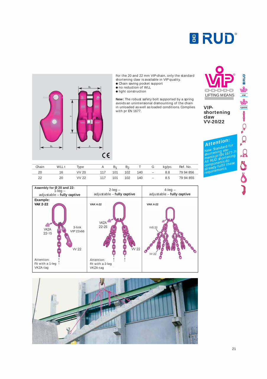
For the 20 and 22 mm VIP-chain, only the standardshortening claw is available in VIP quality.● Chain saving pocket support● no reduction of WLL● light construction
New: The robust safety bolt supported by a springavoids an unintensional dismounting of the chainin unloaded as well as loaded conditions. Complieswith pr EN 1677.
Chain WLL t Type A B1 B2 T G kg/pc. Ref. No.
20 16 VV 20 117 101 102 140 – 8.8 79 94 856
22 20 VV 22 117 101 102 140 – 8.5 79 94 855
Assembly for Ø 20 and 22:1-leg –
adjustable – fully captive2-leg –
adjustable – fully captive4-leg –
adjustable – fully captive
AB1
T
B2
Example:
Attention:Fit with a 1-legVKZA-tag
3-linkVIP 22x66
Attention:Fit with a 2-legVKZA-tag
VAK 4-22VAK 4-22
22
®
LIFTING MEANS
VIP-fool-proof
shackle VV-SCH
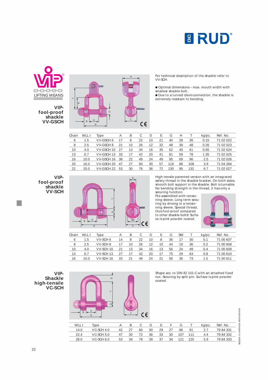
High-tensile patented version with an integratedsafety thread in the shackle bracket. On both sides,smooth bolt support in the shackle. Bolt is turnable.No bending strength in the thread, it has only asecuring function.Pre-assembled with tensio-ning sleeve. Long term secu-ring by driving in a tensio-ning sleeve. Special thread,thus fool-proof compared to other shackle bolts! Surfa-ce is pink powder coated.
VIP-fool-proof
shackle VV-GSCH
For technical description of the shackle refer to VV-SCH.
● Optimal dimensions – max. mouth width with smallest shackle bolt.● Due to a turned clevis connection, the shackle isextremely resistant to bending.
Chain WLL t Type A B C D E G H T kg/pc. Ref. No.6 1.5 VV-GSCH 6 17 8 22 10 21 40 28 36 0.15 71 02 0228 2.5 VV-GSCH 8 21 10 26 12 32 48 39 48 0.26 71 02 023
10 4.0 VV-GSCH 10 27 13 34 16 35 62 45 61 0.65 71 02 02413 6.7 VV-GSCH 13 33 17 42 20 41 81 59 78 1.35 71 02 02516 10.0 VV-GSCH 16 38 22 49 24 49 95 69 96 2.5 71 02 02620 16.0 VV-GSCH 20 47 27 60 30 57 119 88 108 3.9 71 04 28422 20.0 VV-GSCH 22 53 30 76 36 72 130 95 132 6.7 71 02 027
VIP-Shackle
high-tensile VC-SCH
Shape acc. to DIN 82 101-C with an attached fixednut. Securing by split-pin. Surface is pink powdercoated.
WLL t Type A B C D E F G T kg/pc. Ref. No.14.0 VC-SCH 4.0 42 27 60 30 29 27 96 91 2.7 79 84 33122.4 VC-SCH 5.0 47 30 72 36 33 30 107 111 4.4 79 84 33228.0 VC-SCH 6.0 53 34 78 39 37 34 121 120 5.9 79 84 333
A
DT
E
GCB
A
DT
G C
B SW
E
A
D
G
H
BC
T
E
Chain WLL t Type A B C D E G SW T kg/pc. Ref. No.6 1.5 VV-SCH 6 14 8 22 10 8 36 17 30 0.1 71 00 6078 2.5 VV-SCH 8 17 10 26 12 10 44 19 36 0.2 71 00 608
10 4.0 VV-SCH 10 21 13 34 16 13 56 24 49 0.4 71 00 60913 6.7 VV-SCH 13 27 17 42 20 17 75 29 63 0.8 71 00 61016 10.0 VV-SCH 16 33 21 49 24 21 90 36 73 1.5 71 00 611
Sub
ject
to
tec
hn
ical
alt
ern
atio
ns!

23
®
LIFTING MEANS
VIP-IsolatingAssembly
VIP-Isolatinglatch VGIL + VVGSCH
Up to 1000 V
VIP-Balancingassembly"VIP-octopus" for concreteelements
Chain WLL t Type T1 T2 L Weight/ Ref. No. Ref. No.kg VIP-Isolat. assembly VGIL
6 1.5 VGIL-6 71 35 357 1.4 79 84 258 79 84 1618 2.5 VGIL-8 91 43 431 2.4 79 84 259 79 84 162
10 4.0 VGIL-10 108 47 517 4.3 79 84 260 79 84 16313 6.7 VGIL-13 132 54 632 8.2 79 84 261 79 84 16416 10.0 VGIL-16 166 70 760 13.1 79 84 262 79 84 165
Finally!Ensures even load distribution bymeans of a compensating pulleywith a VVGSCH-8.There is neither overload nordeformation of the concrete element.
Chain WLL t Type Ref. No. Ref. No.complete clevis shackle with a deflection pulley
8/6 5.25 VIP-Krake 8 x 5000 79 87 582 79 87 366
RUD VIP Cobra hook:with a robust hook securing,small, handy and easy to hook-in in both diagonal and upperchords.
End linkVA 1
2 LinksVIP-chain
VV GSCH
VGIL
2 LinksVIP-chain
VCGH
VIP-ILG-Isolating assembly
There is a danger of current flow when welding is carried out on suspended loads. The isolating latch isolates up to max. 1,000 V by means of a special non conductive plastic bearing of the clevis shackle bolt.Max operational temperature is +80°C.
T 1
T 2Connection to VGIL:e.g. VV GSCH
VGIL: Isolating latch
Luse
+point
Sub
ject
to
tec
hn
ical
alt
ern
atio
ns!

24
®
LIFTING MEANS
Suitable for standarddumper bins. Easyhandling of the boltand securing hook.
Fool-proof chain con-nection. Connectingbolt and securingstud are pre-assem-bled.VIP-
Rhombic linkVRH
for skipdumpers
VIP-automaticsling hook
VMAGH for skip
dumpers
Type WLL t A B C D E F kg/pc. Ref. No.VCH – 10 10.0 56 70 24 83 76 45 3 51 005
VCH – SL 10 10.0 18 71 42 40 50 47 2.5 85 03 115VCH – 20 20.0 24 62 48 45 76 45 4.2 85 02 313
Chain Type WLL t A B C D E T kg/pc. Ref. No.13 VRH 13 6.7 34 67 130 25 121 1.5 79 84 37013 VMAGH-13 6.7 58 120 47 42 38 150 2.2 79 89 490
AA
B
E
D
BC
T
T
C
D
A
A
C
BF
D
CB
DEE
F
VIP-Container
hook VCH
VCH - 10 t suitable for ISO containeredges. Fix connection by VVS or VVGSCH.Loose component for hook mounting.
VCH - 22 t suitable for ISO containeredges. Clevis connection for the 22 mm VIPchain.VIP chain size can be reduced to 16 mmwhen using a VRG-16 connector.
With patented locking mechanism.
RUD VCH hooks are notsuitable for vertical lift-ing.When the inclinationangle > 30° - accidentalloosening is impossible.
New!VCH-10 VCH SL-10 VCH-20
Suitable for ISO-Container edges. The container hook is equipped with apatented securing device. Therefore thehook cannot fall out of the ISO edge.Easy handling.Inserting: Without operating of securingdevice.Taking out: Only possible when lockingpin is released.RUD VCH-SL hooks are suitable for ver-tical lifts and up to max. 45° inclinationangle (see graphic chart).Clevis connection suits 16 mm VIP chain.
0°-45° 0°-45°
field of use
0-45°
field of use
30-60°
30°-60°
30°-60°
field of use
30-60°
30°-60°
30°-60°
BC
F
DE
A
Sub
ject
to
tec
hn
ical
alt
ern
atio
ns!

25
®
LIFTING MEANS
VIP-Plug-inconnector VERG
VIP-Combi lockVVS-UVVS-VVVS-1/2
VERG to be used as a plug-in bolt for transporta-tion of tools and other similar lifting purposeswhen bores are the only specified lifting pointsavailable.Minimum diameter D, refer to the table, minimumbolt length L is 2 x D. Maximum diameter D = 48 mm.Bore diameter = D + 1 mm. We recommend thatfor vertical lifting purposes, that the VERG be usedwith a spreader bar or a cross beam.
Chain WLL Type Weight Ref. No. Ref. No. Ref. No.t A1 A2 B C D T kg/pc. VVS-U VVS-1/2 VVS-V
universal one side two sidesfool proof fool proof
6 1.5 VVS 6 7 14 50 8.5 14 40 0.09 79 88 419 79 84 057 79 84 0508 2.5 VVS 8 9 19 64 10.5 19 53 0.17 79 85 714 79 84 058 79 84 051
10 4.0 VVS 10 11 23 80 13 23 70 0.42 79 85 715 79 84 059 79 84 05213 6.7 VVS 13 15 27 97 17 27 81 0.64 79 84 293 79 84 060 79 84 05316 10.0 VVS 16 18 34 125 21 34 104 1.5 79 86 984 79 84 061 79 84 05420 16.0 VVS 20 – 42 155 27 41 124 3 79 84 055 – – 22 20.0 VVS 22 – 47 172 30 46 133 3.9 79 84 056 – –
A2
B
CD
T
Various external connec-tions e.g. lifting points,metalic grabs, etc. canbe mounted in the locking bracket (A2).
The bracket halves canbe optionally combinedto suit the application.
No movement, thusdamage of the securing
fool-proof on both sides
spring or the sleeves ofthe retention bolt isavoided.
In the fool proof-brack-et with a forged nose,only the correct chainsize or overload indica-tor can be (A1) fitted.
fool-proof chain connection
on one side
VVS-V
VVS-U universal
VVS-1/2
Chain WLL t Type Dmin D* L* A min. T6 1.5 VERG – 6 17 11 208 2.5 VERG – 8 22
Indicate sizes L and D 15 26
10 4.0 VERG – 10 28when ordering!
18 3313 6.7 VERG – 13 36 24 4216 10.0 VERG – 16 45 29 54
A1
World
champion
in load
capacity!
D
L
use
+point
Sub
ject
to
tec
hn
ical
alt
ern
atio
ns!
Attention:In the event of any lift-ing procedure, attach-ment should always be at the collar.The plug-in connectorsare non stock items andtheir production is sub-ject to customer requi-rement. Thus bear in mind therespective delivery peri-ods.
26
®
LIFTING MEANS
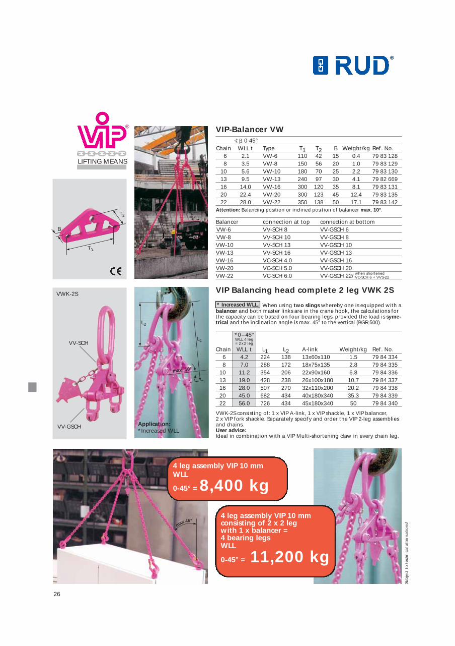
VIP Balancing head complete 2 leg VWK 2S
�� 0-45°Chain WLL t Type T1 T2 B Weight/kg Ref. No.
6 2.1 VW-6 110 42 15 0.4 79 83 1288 3.5 VW-8 150 56 20 1.0 79 83 129
10 5.6 VW-10 180 70 25 2.2 79 83 13013 9.5 VW-13 240 97 30 4.1 79 82 66916 14.0 VW-16 300 120 35 8.1 79 83 13120 22.4 VW-20 300 123 45 12.4 79 83 13522 28.0 VW-22 350 138 50 17.1 79 83 142
Attention: Balancing position or inclined position of balancer max. 10°.
Balancer connection at top connection at bottomVW-6 VV-SCH 8 VV-GSCH 6VW-8 VV-SCH 10 VV-GSCH 8VW-10 VV-SCH 13 VV-GSCH 10VW-13 VV-SCH 16 VV-GSCH 13VW-16 VC-SCH 4.0 VV-GSCH 16VW-20 VC-SCH 5.0 VV-GSCH 20VW-22 VC-SCH 6.0 VV-GSCH 22/
VIP-Balancer VW
T1
L1
L2
T2
B
VWK-2S
VV-SCH
VV-GSCH Application:*Increased WLL
4 leg assembly VIP 10 mmconsisting of 2 x 2 leg with 1 x balancer =4 bearing legsWLL
11,200 kg
when shortenedVC-SCH 6 + VVS-22
max. 10°
max.45°
0-45° =
4 leg assembly VIP 10 mmWLL
0-45° = 8,400 kg
When using two slings whereby one is equipped with abalancer and both master links are in the crane hook, the calculations forthe capacity can be based on four bearing legs; provided the load is syme-trical and the inclination angle is max. 45° to the vertical (BGR 500).
*0– 45°WLL 4 leg= 2x2 leg
Chain WLL t L1 L2 A-link Weight/kg Ref. No.6 4.2 224 138 13x60x110 1.5 79 84 3348 7.0 288 172 18x75x135 2.8 79 84 335
10 11.2 354 206 22x90x160 6.8 79 84 33613 19.0 428 238 26x100x180 10.7 79 84 33716 28.0 507 270 32x110x200 20.2 79 84 33820 45.0 682 434 40x180x340 35.3 79 84 33922 56.0 726 434 45x180x340 50 79 84 340
VWK-2S consisting of: 1 x VIP A-link, 1 x VIP shackle, 1 x VIP balancer, 2 x VIP fork shackle. Separately specify and order the VIP 2-leg assembliesand chains.User advice:Ideal in combination with a VIP Multi-shortening claw in every chain leg.
Sub
ject
to
tec
hn
ical
alt
ern
atio
ns!
* Increased WLL.

27
®
LIFTING MEANS
Chain WLL t Type (A)/A (B) (C) (T)/T (kg/pc.) (Ref. No.)/Ref. No.
4 0.63 – /UW PP-4 – /34 – – – /51 – / 0.22 – /79 90 878
6 1.5 (VWA 6)/UW PP-6 (30)/39 6.1 7.2 (50)/65 (0.2)/0.43 (71 00 629)/79 90 879
8 2.5 – /UW PP-8 (37)/53 8.2 9.7 /79 /0.98 /79 90 880
10 4.0 (VWA 10)/UW PP-10 (46)/68 10.3 12.2 (82.5)/97 (0.7)/1.9 (71 00 631)/79 90 881
13 6.7 (VWA 13)/UW PP-13 (60)/83 13.4 15.7 (92)/119 (1.4)/3.6 (71 00 632)/79 90 882
16 10.0 – /UW PP-16 (70)/88 16.4 19.2 (115)/132 (2.5)/4.8 – /79 92 861
20 16.0 (VWA 20)/ – (100)/ – 21 25 (147)/ – (6.5)/ – (79 90 723)/ –
22 20.0 (VWA 22)/ – (102)/ – 23 28 (147)/ – (6.8)/ – (71 00 634)/ –
VIP-UniversalSwivel-PP-UW-Patent
VIP-SwivelconnectorVWA
Chain WLL t Type A B C D E T kg/pc. Ref. No.
6 1.5 VRG 6 17 30 37 16 8 28 0.07 71 00 469
8 2.5 VRG 8 23 40 50 22 10 37 0.2 71 00 470
10 4.0 VRG 10 28 50 60 26 13 46 0.3 71 00 471
13 6.7 VRG 13 36 64 75 32 17 58 0.7 71 00 472
16 10.0 VRG 16 45 75 92 40 20 74 1.1 71 00 473
20 16.0 VRG 20 58 92 118 52 28 94 3.1 71 03 384
22 20.0 VRG 22 62 102 124 52 32 94 3.5 71 01 611
VIP-ConnectorVRG
A single component for extrinsic connections to clevises, flangesetc.
Complete with a pre-assembled connecting bolt and tensioningsleeve.
T
E
A
C
D
B
B
(A)
(T)
C
T
A
use
+point
Special universal swivel PowerPoint:A patented clevis connection design hence a universalconnection which is loadable from any direction andfacilitates the shortest combination possibilities.Only RUD-approved VIP chains and components mustbe used.1. VIP Cobra-Eye Hook VCÖH, see page 162. B-Link for PowerPoint PP-(WLL)-B, see page 11Note: VIP chain connection is designed fool proof.When assembling component 1 and 2, please payattention to the correct Working Load Limits.
Special VWA:Owing to the adapter bar, it can be fool-proof con-nected to all VIP clevis components. The sealed bodymakes it more resistant to dirt. Do not bend the appliance! The installation of the adapter should bedone in such a way that no bending occurs during use.Supply is subject to stock availability. This type willsoon be replaced.
The following applies to both versions:The BGR stipulates that twisted slings are not to be loaded. This requirement is automatically achieved by theball bearing swivel - swivelling under load. Not designed for continuous use.
Special Links see page 11
Co
bra
-Eye
Ho
ok
see
pag
e 16
Sub
ject
to
tec
hn
ical
alt
ern
atio
ns!
28
®
LIFTING MEANS
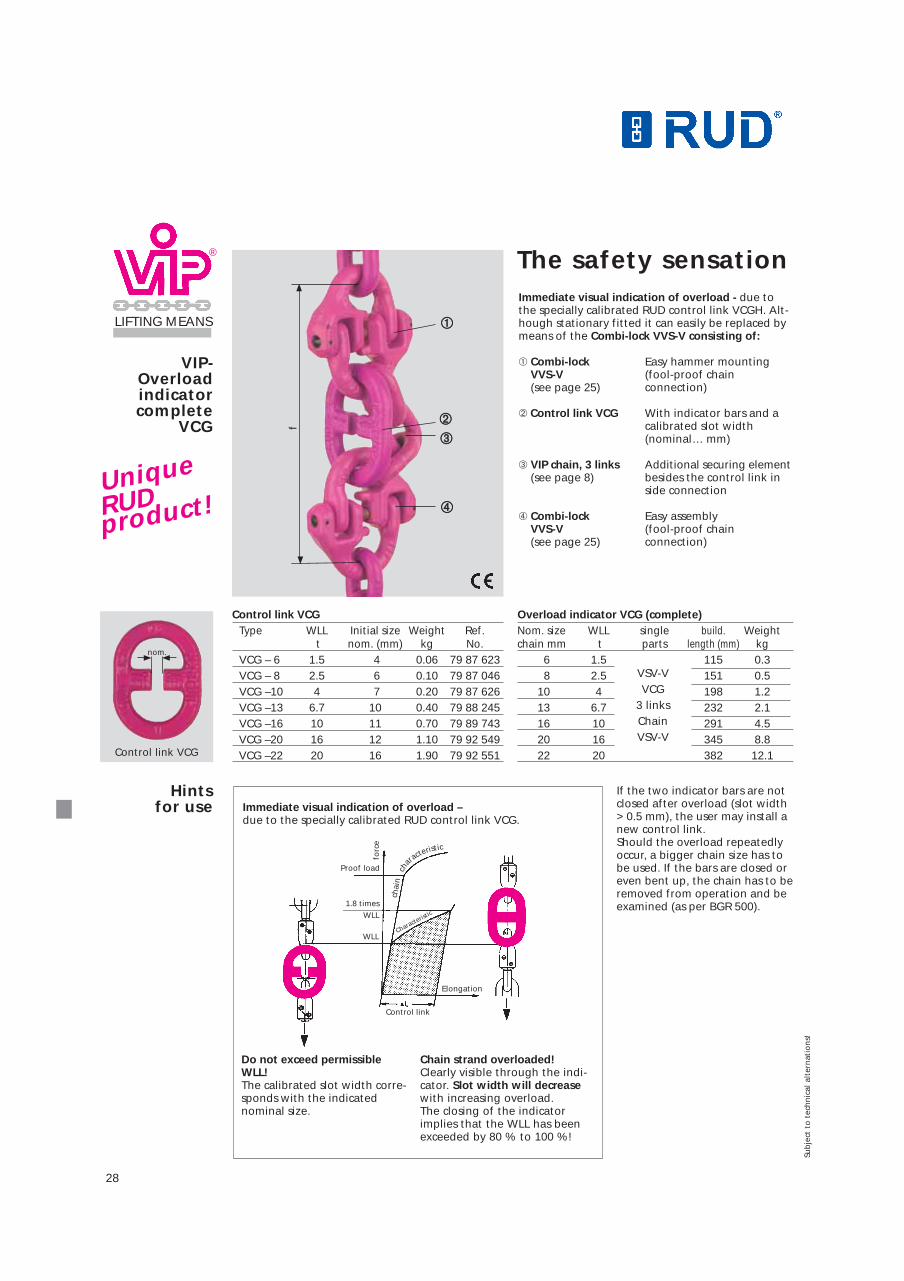
VIP-Overloadindicatorcomplete
VCG
Immediate visual indication of overload - due tothe specially calibrated RUD control link VCGH. Alt-hough stationary fitted it can easily be replaced bymeans of the Combi-lock VVS-V consisting of:
➀ Combi-lock Easy hammer mountingVVS-V (fool-proof chain (see page 25) connection)
➁ Control link VCG With indicator bars and a calibrated slot width (nominal… mm)
➂ VIP chain, 3 links Additional securing element(see page 8) besides the control link in
side connection
➃ Combi-lock Easy assembly VVS-V (fool-proof chain (see page 25) connection)
Overload indicator VCG (complete)Nom. size WLL single build. Weightchain mm t parts length (mm) kg
6 1.5 115 0.38 2.5 VSV-V 151 0.5
10 4 VCG 198 1.213 6.7 3-Gld. Kette 232 2.116 10 VSV-V 291 4.520 16 345 8.822 20 382 12.1
Control link VCGType WLL Initial size Weight Ref.
t nom. (mm) kg No.VCG – 6 1.5 4 0.06 79 87 623VCG – 8 2.5 6 0.10 79 87 046VCG –10 4 7 0.20 79 87 626VCG –13 6.7 10 0.40 79 88 245VCG –16 10 11 0.70 79 89 743VCG –20 16 12 1.10 79 92 549VCG –22 20 16 1.90 79 92 551
If the two indicator bars are notclosed after overload (slot width> 0.5 mm), the user may install anew control link. Should the overload repeatedlyoccur, a bigger chain size has tobe used. If the bars are closed oreven bent up, the chain has to beremoved from operation and beexamined (as per BGR 500).
Hints for use
➀➀
➃➃
➁➁
➂➂
f
Control link VCG
nom.
The safety sensation
UniqueRUDproduct!
VSV-VVCG
3 linksChainVSV-V
Sub
ject
to
tec
hn
ical
alt
ern
atio
ns!Immediate visual indication of overload –due to the specially calibrated RUD control link VCG.
Do not exceed permissibleWLL!The calibrated slot width corre-sponds with the indicatednominal size.
Chain strand overloaded!Clearly visible through the indi-cator. Slot width will decreasewith increasing overload. The closing of the indicatorimplies that the WLL has beenexceeded by 80 % to 100 %!
Proof load
Control link
Elongation
Characterist
ic1.8 times
WLL
WLL
forc
e
chai
nch
aracte
ristic

29
VIP-Master link VAK 1/2
VIP-Master link VAK 3/4
Mecano "in miniature" for small loads up to 1320 kg!
A WORLD SPECIALTY–the one and only Mini mecano system 4 mm!
VIP chain assembly, fixed length
Chain WLL t Type A B T Weight/kg Ref. No. 4 0.63 VAK 1/2 – 4 9 30 55 0.1 79 84 4454 1.32 VAK 3/4 – 4 10 35 106 0.3 79 84 447
VIP-Mini-lifterVML-2 – completewith shorteners – »patent«
VIP-Mini-lifterVML-4
Chain WLL t Type A B T Weight/kg Ref. No.4 0.63/0.88 VML 2 – 4 10 30 66 0.26 79 84 4784 1.32/0.95 VML 4 – 4 10 35 150 0.85 79 84 479
VIP-Mini-hookVMH-4
*VIP-End link VEA-4!
VIP-Mini-couplingshackle VMKS
Chain WLL t Type MW A B T D H Weight/kg Ref. No.4 0.63 VMH – 4 18 - - 56 - 13 0.12 79 84 4394 0.63 VMKS – 4 - 30 14 42 10 - 0.12 79 85 2434 0.63 VEA – 4 - - - - - - 0.05 79 90 215
VIP chain assembly, can be shortened
MW
TH
B
DA T
B
A
T T
B
T
L
B
A
T
VAK 3/4
VML-2 VML-4
VMH-4 VMKS
VAK 1/2®
B
A
A
VEA-4
use
+point
*
Sub
ject
to
tec
hn
ical
alt
ern
atio
ns!

30
®
LIFTING MEANS
VIP-Spreader bar fixed
VSRS
VIP Spreader bar fixed VSRSWhen ordering please indicatethe effective length L of the spreader bar!
Spreader bars are also availablewith chain slings. When order-ing, specify the type of masterlink and the required inclinationangle �.
VIP spreader bars are non stockitems and their production is sub-ject to customer requirement.Thus bear in mind the respectivedelivery periods.
Surface:Effective length L up to2500 mm: pink powder coated.
Effective length L beyond2500 mm: yellow painted.
for chain sizes: 6 to 13
for chain sizes: 16 to 22
Connectionwith VVS
Connectionwith VV-GSCH
Chain Possible WLL kg Weightsize Type working length L T 0 – 45° 45 – 60° kg/pc. Ref. No.
6 VSRS-6 500 – 4000 mm 190 2100 1500 86 00 1108 VSRS-8 500 – 5000 mm 240 3500 2500 86 00 11110 VSRS-10 500 – 5000 mm 320 5600 4000 86 00 11213 VSRS-13 1000 – 5000 mm 350 9500 6700 86 00 11316 VSRS-16 1000 – 5000 mm 250 14000 10000 86 00 11420 VSRS-20 1000 – 5000 mm 285 22400 16000 86 00 11522 VSRS-22 1000 – 5000 mm 290 28000 20000 86 00 116
dep
end
ing
on
wo
rkin
g le
ng
th L
Alternatively:
Lifting points PP-Power-Point! Su
bje
ct t
o t
ech
nic
al a
lter
nat
ion
s!

31
®
LIFTING MEANS
VIP-Spreader baradjustable VSRV
for chain sizes: 6 to 13
for chain sizes: 16 to 22
Connec-tion with VV-GSCH
Connectionwith VVS 1/2
VIP Spreader bar adjustableVSRVWhen ordering please indicateworking length L of the spreaderbar!
Adjustable spreader bars are alsoavailable with chain slings. Whenordering, specify the type ofmaster link and the requiredinclination angle �.
VIP spreader bars are non stockitems and their production issubject to customer requirement.Thus bear in mind the respectivedelivery periods.
Surface: Pink powder coated.
Lmin. depends on Lmax. and nomi-nal size.
Chain possible working WLL kg Weightsize Type length Lmax. T � � 45° � 45 – 60° Kg/St. Ref. No.
6 VSRV-6 1500 – 4000 mm 200 2100 1500 86 00 1208 VSRV-8 1500 – 4000 mm 250 3500 2500 86 00 12110 VSRV-10 1500 – 4000 mm 330 5600 4000 86 00 12213 VSRV-13 1500 – 4000 mm 360 9500 6700 86 00 12316 VSRV-16 1500 – 4000 mm 250 14000 10000 86 00 12420 VSRV-20 1500 – 4000 mm 285 22400 16000 86 00 12522 VSRV-22 1500 – 4000 mm 290 28000 20000 86 00 126
dep
end
ing
on
wo
rkin
g le
ng
th L
Edge protectingdevice RSK
*further sizesupon request.
RUD-RSK system made of dura-ble edge-robust polyurethane.
Flexible in all directions. Manuallymovable along the chain. Evenload distribution due to a diagonaltransversal crucifix. Max. 2 m canbe supplied.
Chain size Type A B Lmax. Ref. No.6 RSK – 6 27 27 2000 56 0338 RSK – 8 33 33 2000 56 037
10 RSK – 10 38 38 2000 55 81013 RSK – 13 50 50 2000 56 038*
use
+point
Sub
ject
to
tec
hn
ical
alt
ern
atio
ns!

32
®
LIFTING MEANS
Examples ofapplications
Order references
Combinationpossibilities
Assembledendless chains
1-leg 2-leg 3- or 4-leg
Order reference:VIP-G1... VIP-G2...
VIP-G3...or VIP-G4...
1-leg adjustable*** 2-leg adjustable* 3- or 4-leg adjustable
Order reference:VIP-G1-V1-... VIP-G2-V2-...
VIP-G3-V3-...or VIP-G4-V4...
VIP single endless chain – fixed
Order examples:**1 pc VKREV-8 x 2000 = single endless chain, adjustable in RUD special quality VIP, 8 = chain dia. x 2000 =max. working length size L in mm.*** in case of long adjustable assemblies it is recommended to mount the multi claw VMKV in the lowerpart of the chain. Indicate Lv when ordering, e.g. VIP-G2-V2-VCGH/10x5000 Lv-2000.
-special connecting lock*for VIP endless chains:diameters 20 and 22 mm.Please ask for details.
Order reference:*VIP-G2-V2-VCGH/10x2000= 2 leg version in RUD special quality VIP with 2 leg shortenings (VMVK).VCGH = End component/10 = chain diameter x 2000 = max. working length size L in mm.
VCGH VWH UW-PPVAGH VA/VB
VKRE
VIP single endless chain – adjustable
VKREV
VIP double endless chain – fixed
VKRD
VIP double endless chain – adjustable
VKRDV
VMVK VGSCH VCH-SLVVH
**Endless chain – fixed
▲
▲
L
Sub
ject
to
tec
hn
ical
alt
ern
atio
ns!

33
LIFTINGMEANS
RUD-lifting means are manufac-tured acc. to DIN 15428. All weldsare carried out by qualified wel-ders. Welds are crack detected.
An inspection certificate as well asregister card for load carryingmeans for regular checks and userinformation will be supplied.
Just let us know your designrequirements or give us a shorttechnical description eg. theWLL, respective dimensions etc.
Spreader bars - fixed -adjustable
Fork lift attachmentsC-hooks
Special hooksSpecial lifting meansSpecial com-ponents
use
+point
Sub
ject
to
tec
hn
ical
alt
ern
atio
ns!
hei
gth
“B
”m
axim
umw
idth
“Z”

34
● All parts are either 100 % crack detected or proof loaded accord. to EN 1677.
● All original bolts from RUD are 100 % crack detected. ● Safety factor 4 : 1 in any direction.● The types VRS, VRM and VLBG have to be adjusted to
the load direction.● RUD patented features such as clamping spring (VLBS)
for noise reduction and distance lugs for a perfect rootpass weld increase the ease of use.
● RUD CD-ROM and slide chart “RUD-MULTI-MASTER“facilitate the correct selection of lifting points.
● Low installation height, high dynamic and static strength.The RUD lifting and lashing points CD-ROM simplifies the(lifting/lashing points) correct layout.
● RUD Lifting Points are in accordance with DIN EN 818 and1677 with a dynamic loading of more than 20,000 loadcycles.The BG recommends: At high dynamic applications with high load cycles (permanent operation), the WLL must bereduced.
RUD Lifting Points = Advantages!
PP-S (Vario)PowerPoint-Star
PP-B (Vario)PowerPoint-B
PP-VIP (Vario)PowerPoint-VIP
VLBG – Load Ring WBG-VLoad Ring Vario
WBG-
V 0.
3 t
WBG-
V 0.
45 t
WBG-
V 0.
6 t
WBG-
V 1.
0 t
WBG-
V 1.
3 t
WBG-
V 1.
8 t
WBG-
V 2
t
WBG-
V 3.
5 t
WBG-
V 5
t
Type
PP-S
0.6
3 t
PP-S
1.5
t
PP-S
2.5
t
PP-S
4 t
PP-S
6.7
t
PP-S
8 t
VLBG
0.3
t
VLBG
0.6
3 t
VLBG
1 t
VLBG
1.5
t
VLBG
2.5
t
VLBG
4 t
VLBG
4 t
VLBG
5 t
VLBG
7 tS
PEC.
VLBG
8 t
VLBG
10
t
VLBG
15
t
VLBG
20
t
LBG(
3) M
16 R
S 1t
LBG(
3) M
20 R
S 2t
unsy
mm
etric
alun
sym
met
rical
Thre
ad si
zeTh
read
size
G
M M M M M M M M M M M M M M M M M M M M M M M M M M M M M M12 16 20 24 30 36 8 10 12 16 20 24 27 30 36 36 42 42 48 16 20 8 10 12 14 16 18 20 24 30
1 0° 0.6 1.5 2.5 4 6.7 10 0.3 0.6 1 1.5 2.5 4 4 5 7 8 10 15 20 1 2 0.6 0.9 1.2 2.0 2.6 3.6 4 7 10
2 0° 1.2 3 5 8 13.4 20 0.6 1.2 2 3 5 8 8 10 14 16 20 30 40 2 4 1.2 1.8 2.4 4.0 5.2 7.2 8 14 20
1 90° 0.6 1.5 2.5 4 5 8 0.3 0.6 1 1.5 2.5 4 4 5 7 8 10 15 20 1 2 0.3 0.45 0.6 1.0 1.3 1.8 2 3.5 5(0.4) (0.6) (0.7) (1.25) (1.5) (2.0) (2.5) (4) (6)
2 90° 1.2 3 5 8 10 16 0.6 1.2 2 3 5 8 8 10 14 16 20 30 40 2 4 0.6 0.9 1.2 2.0 2.6 3.6 4 7 10(0.8) (1.2) (1.5) (2.5) (3) (4.0) (5) (8) (12)
2 0- 0.8 2.1 3.5 5.6 7.1 11.2 0.4 0.8 1.4 2.1 3.5 5.6 5.6 7 9.8 11.2 14 21 28 1.4 2.8 0.4 0.6 0.8 1.4 1.8 2.5 2.8 4.9 745°
2 45- 0.6 1.5 2.5 4 5 8 0.3 0.6 1 1.5 2.5 4 4 5 7 8 10 15 20 1 2 0.3 0.4 0.6 1.0 1.3 1.8 2 3.5 560°
2 0.6 1.5 2.5 4 5 8 0.3 0.6 1 1.5 2.5 4 4 5 7 8 10 15 20 1 2 0.3 0.4 0.6 1.0 1.3 1.8 2 3.5 5
3+40-
1.3 3.2 5.3 8.4 10.5 16.8 0.6 1.3 2.1 3.1 5.2 8.4 8.4 10.514.716.8 21 31.5 42 2.1 4.2 0.6 0.9 1.2 2.1 2.7 3.7 4.2 7.3 10.545°
3+445-
0.9 2.2 3.8 6 7.5 12 0.4 0.9 1.5 2.2 3.7 6 6 7.5 10.4 12 15 22.5 30 1.5 3 0.4 0.6 0.9 1.5 1.9 2.7 3 5.2 7.560°
3+4 0.6 1.5 2.5 4 5 8 0.3 0.6 1 1.5 2.5 4 4 5 7 8 10 15 20 1 2 0.3 0.4 0.6 1.0 1.3 1.8 2 3.5 5
M M M M M M M M M M M M M M M M M M M M M M M M M M M M M M12 16 20 24 30 36 8 10 12 16 20 24 27 30 36 36 42 42 48 16 20 8 10 12 14 16 18 20 24 30
Thread sizes
M 6- M150
Imperial (UNC,...) and special lengths
on request
Lifting Points - for bolting -Maximum transport weight “G“ in “tonnes“ with different lifting methods
Num
ber o
f leg
sLo
ad d
irecti
on
Sub
ject
to
tec
hn
ical
alt
ern
atio
ns!

35
use
+point
2x 4x 4x 4x 6x 6x
M M M M M M M M M M M M M M M M M M M M M M M M M M M M M M M M M M M M M M M M M M M M M M33 36 39 42 48 42-52 56 64 56-85 72-76 80-85 90 90-150 8 10 12 16 20 24 30 36 42 48 12 16 20 24 30 6 8 10 12 14 16 20 24 30 36 42 48 16 20 30 30 36 48
We have the right tools for you. Call us! Phone no. or e-mail:
WBGLoad Ring
RBG/VRBG Load Ring
VRS StarpointVario eyebolt
RS/RM High-tensile eye bolt/eye nut
+49 7361-504-1170 or [email protected] perfect service for the CAD department.We provide you with geometry datas for your design.Order our CD-ROM for the calculation of the right lifting point.Especially useful for the designer is the 3D-presentation of the liftingpoints.
...or www.rud.comClick on lifting means lifting points
WBG
6-SP
EC.
WBG
8 t
WBG
8-SP
EC.
WBG
10 t
WBG
10 t
WBG
10-SP
EC.
WBG
15 t
WBG
15 t
WBG
15- SP
EC.
WBG
25 t
WBG
30 t
WBG
35 t
WBG
35-SP
EC.
VRS M
8
VRM
M8
VRS M
10
VRM
M10
VRS M
12VR
M M1
2VR
S M16
VRM
M16
VRS M
20VR
M M2
0VR
S M24
VRM
M24
VRS M
30VR
M M3
0
VRS M
36
VRS M
42
VRS M
48IN
OX M
12IN
OX M
16IN
OX M
20IN
OX M
24IN
OX M
30
RS M
6
RS M
8
RS M
10
RS M
12
RS M
14
RS M
16
RS M
20
RS M
24
RS M
30
RS M
36
RS M
42
RS M
48
RBG
3 t
VRBG
10
t
VRBG
16
t
VRBG
30
t
VRBG
50
t
VRBG
80
t
VRMStarpointeyenut
INOX-STAR
2x 4x 4x 4x 6x 6x
M M M M M M M M M M M M M M M M M M M M M M M M M M M M M M M M M M M M M M M M M M M M M M33 36 39 42 48 42-52 56 64 56-85 72-76 80-85 90 90-150 8 10 12 16 20 24 30 36 42 48 12 16 20 24 30 6 8 10 12 14 16 20 24 30 36 42 48 16 20 30 30 36 48
12.512.512.5 16 16 16 25 25 25 35 35 35 35 1 1 2 4 6 8 12 16 24 32 1.2 2.4 3.6 5.2 - 0.4 0.8 1 1.6 3 4 6 8 12 16 24 32 3 10 16 30 50 80
25 25 25 32 32 32 50 50 50 70 70 70 70 2 2 4 8 12 16 24 32 48 64 2.4 4.8 7.2 10.4 - 0.8 1.6 2 3.2 6 8 12 16 24 32 48 64 6 20 32 60 100 160
6 8 8 10 10 10 15 15 15 25 30 35 35 0.4 0.4 0.7 1.5 2.3 3.2 4.5 7 9 12 0.5 1.0 2.0 2.5 - 3 10 16 30 50 80(7.5) (10) (10) (12.5)(12.5)(12.5) (18) (18) (18) (30) (35) (40) (40)
12 16 16 20 20 20 30 30 30 50 60 70 70 0.8 0.8 1.5 3 4.6 6.4 9 14 18 24 1.0 2.0 4.0 5.0 - 6 20 32 60 100 160(15) (20) (20) (25) (25) (25) (36) (36) (36) (60) (70) (80) (80)
8.4 11.211.2 14 14 14 21 21 21 35 42 49 49 0.56 0.56 1 2.1 3.2 4.5 6.3 9.8 12.616.8 0.7 1.4 2.8 3.5 - 4.2 14 22.4 42 70 112(10.5) (14) (14) (17.5)(17.5)(17.5)(25.2)(25.2)(25.2) (42) (49) (56) (56)
6 8 8 10 10 10 15 15 15 25 30 35 35 0.4 0.4 0.7 1.5 2.3 3.2 4.5 7 9 12 0.5 1.0 2.0 2.5 - 3 3 10 16 30 50 80(7.5) (10) (10) (12.5)(12.5)(12.5) (18) (18) (18) (30) (35) (40) (40)
6 8 8 10 10 10 15 15 15 25 30 35 35 0.4 0.4 0.7 1.5 2.3 3.2 4.5 7 9 12 0.5 1.0 2.0 2.5 - 3 8 3 10 16 30 50 80(7.5) (10) (10) (12.5)(12.5)(12.5) (18) (18) (18) (30) (35) (40) (40)
12.6 16.8 16.8 21 21 21 31.5 31.5 31.5 52.5 63 73.5 73.5 0.8 0.8 1.5 3.1 4.8 6.7 9.4 14.7 18.9 25 1.0 2.1 4.2 5.3 - 25 6.3 21 33.6 63 105 168(15.7) (21) (21) (26.2)(26.2)(26.2) (38) (38) (38) (63) (73.5) (84) (84)
9 12 12 15 15 15 22.5 22.5 22.5 37.5 45 52.5 52.5 0.6 0.6 1.1 2.2 3.4 4.8 6.7 10.5 13.5 18 0.7 1.5 3.0 3.7 - 10,5 4.5 15 24 45 75 120(11.2) (15) (15) (18.8)(18.8)(18.8) (27) (27) (27) (45) (52.5) (60) (60)
6 8 8 10 10 10 15 15 15 25 30 35 35 0.4 0.4 0.7 1.5 2.3 3.2 4.5 7 9 12 0.5 1.0 2.0 2.5 - 7 3 3 10 16 30 50 80(7.5) (10) (10) (12.5)(12.5)(12..5) (18) (18) (18) (30) (35) (40) (40)
New!
Sub
ject
to
tec
hn
ical
alt
ern
atio
ns!
We recommend
to use either
“VRS Starpoint”
or “PowerPoint”
which can be adjusted
to the direction
of pull!
New!
Lifting Points - for bolting -Maximum transport weight “G“ in “tonnes“ with different lifting methods

36
Lifting Points - for welding -Maximum transport weight “G“ in “tonnes“with different slinging methods
all various all various
Type
WPP
0.63
t
WPP
1.5
t
WPP
2.5
t
WPP
4 t
WPP
6.7
t
WPP
8 t
WPPH
0.6
3 t
WPPH
1.5
t
WPPH
2.5
t
WPPH
4 t
WPPH
6.7
t
WPPH
8 t
VLBS
1.5
t
VLBS
2.5
t
VLBS
4 t
VLBS
6.7
t
VLBS
10
t
VLBS
16
t
LBS(
1) R
S 0.5
t
LBS(
3) R
S 1 t
LBS(
5) R
S 2 t
VRBS
4 t
VRBS
6.7
t
VRBS
10
t
VRBS
16
t
VRBS
30
t
VRBS
50
t
Weld
1 0°
2 0°
1 90°
2
2
2
2
90°
0-45°
45-60°
3+4 0-45°
3+4
3+4
45-60°
unsy
mm
etric
alun
sym
met
rical
LBS/VLBS Load ring for welding
VRBSEye Plate for welding
� � ��
G
We have the right tools for you. Call us! Phone no. or e-mail:
Num
ber o
f leg
sLo
ad d
irecti
on
0.6 1.5 2.5 4 6.7 10 0.6 1.5 2.5 4 6.7 10 1.5 2.5 4 6.7 10 16 0.5 1 2 4 6.7 10 16 30 50
1.2 3 5 8 13.4 20 1.2 3 5 8 13.4 20 3 5.0 8 13.4 20 32 1 2 4 8 13.4 20 32 60 100
0.6 1.5 2.5 4 5 8 0.6 1.5 2.5 4 5 8 1.5 2.5 4 6.7 10 16 0.5 1 2 4 6.7 10 16 30 50
1.2 3 5 8 10 16 1.2 3 5 8 10 16 3 5.0 8 13.4 20 32 1 2 4 8 13.4 20 32 60 100
0.8 2.1 3.5 5.6 7.1 11.2 0.8 2.1 3.5 5.6 7.1 11.2 2.1 3.5 5.6 9.38 14 22.4 0.7 1.4 2.8 5.6 9.38 14 22.4 42 70
0.6 1.5 2.5 4 5 8 0.6 1.5 2.5 4 5 8 1.5 2.5 4 6.7 10 16 0.5 1 2 4 6.7 10 16 30 50
0.6 1.5 2.5 4 5 8 0.6 1.5 2.5 4 5 8 1.5 2.5 4 6.7 10 16 0.5 1 2 4 6.7 10 16 30 50
1.3 3.2 5.3 8.4 10.5 16.8 1.3 3.2 5.3 8.4 10.5 16.8 3.15 5.25 8.4 14.1 21 33.6 1.05 2.1 4.2 8.4 14.1 21 33.6 63 105
0.9 2.2 3.8 6 7.5 12 0.9 2.2 3.8 6 7.5 12 2.25 3.75 6 10.1 15 24 0.75 1.5 3 6 10.1 15 24 45 75
0.6 1.5 2.5 4 5 8 0.6 1.5 2.5 4 5 8 1.5 2.5 4 6.7 10 16 0.5 1 2 4 6.7 10 16 30 50
HV HV HV HV HV HV HV HV HV HV HV HV HV HV HV HV HV HV HV HV HV HV HV3.5 4.5 3+4.5 3+5 3+8 3+10 3.5 4.5 3+5 3+6 3+8 3+10 5+3 7+3 8+3 12+4 16+4 25+6 5+3 8+3 12+4 4+3 5.5+3 8.5+4 8.5+4 15+4 25+8
New! New!
Sub
ject
to
tec
hn
ical
alt
ern
atio
ns!
WPP-Serie PowerPoint
WPPH-SeriePowerPoint
+49 7361-504-1170 or [email protected] perfect service for the CAD department.We provide you with geometry datas for your design.Order our CD-ROM for the calculation of the right lifting point.Especially useful for the designer is the 3D-presentation of the liftingpoints.
...or www.rud.comClick on lifting means lifting points

VRBS
S 6.7
t
VRBS
S 10
t
VRBS
S 16
t
VRBK
4 t
VRBK
6.7
t
VRBK
10t
VRBKLoad ring for welding
with a positioningmechanism
VRBKLoad ring for welding
on edges
6.7 10 16 4 6.7 10
13.4 20 32 8 13.4 20
6.7 10 16 4 6.7 10
13.4 20 32 8 13.4 20
9.38 14 22.4 5.6 9.38 14
6.7 10 16 4 6.7 10
6.7 10 16 4 6.7 10
14.1 21 33.6 8.4 14.1 21
10.1 15 24 6 10.1 15
6.7 10 16 4 6.7 10
HV HV HV HV HV HV5.5+3 6+4 8.5+4 4+3 5+3 8+3
New! New!
37
Sub
ject
to
tec
hn
ical
alt
ern
atio
ns!
Lifting Points - for welding -Maximum transport weight “G“ in “tonnes“with different slinging methods
RUD Lifting Points are in accordance with DIN EN 818and 1677 with a dynamic loading of more than20,000 load cycles.
The BG recommends: At high dynamic applications with high load cycles (permanent operation), the WLL must be reduced.

38
**With flexible VMVK, shortening can be done at any position of the chain leg since the claw can be moved along the chain.
VIP-VSK-KZA
VCGHVCGHVKSPS-R VMVK**
Standard length 3500
Lever foldable
Ver
sio
n –
A–
(VM
VK
)V
ersi
on
–B
– (V
VH
)Ex
amp
le –
C–
Chain Type of chain Lashing Tensioner Lmin Weight Ref. no.dia. complete capacity*** Standard Tension mm kg/pc.
daN ForceType STF in daN (kp)
6 VIP-VSK-6-A-VKSPS 3000 VKSPS-6 1500 760 4.3 7100 7856 VIP-VSK-6-A-VKSPS-R 3000 VKSPS-R-6 1500 760 4.5 7990 2498 VIP-VSK-8-A-VKSPS* 5000 VKSPS-8 2500 900 8.5 7100 7868 VIP-VSK-8-A-VKSPS-R* 5000 VKSPS-R-8 2500 920 9.0 7987 52110 VIP-VSK-10-A-VKSPS* 8000 VKSPS-10 2800 1075 12.0 7100 78710 VIP-VSK-10-A-VKSPS-R* 8000 VKSPS-R-10 2800 1075 12.2 7100 81313 VIP-VSK-13-A-VKSPS* 13400 VKSPS-13 3600 1400 23.5 7100 78813 VIP-VSK-13-A-VKSPS-R* 13400 VKSPS-R-13 3600 1400 24.5 7100 81416 VIP-VSK-16-A-VKSPS 20000 VKSPS-16 3600 1750 36.0 7104 30916 VIP-VSK-16-A-VKSPS-R 20000 VKSPS-R-16 3600 1750 37.0 7990 250
6 VIP-VSK-6-B-VKSPS 3000 VKSPS-6 1500 840 4.0 7989 5116 VIP-VSK-6-B-VKSPS-R 3000 VKSPS-R-6 1500 840 4.2 7990 2478 VIP-VSK-8-B-VKSPS* 5000 VKSPS-8 2500 1000 8.0 7989 5128 VIP-VSK-8-B-VKSPS-R* 5000 VKSPS-R-8 2500 1020 8.5 7989 51310 VIP-VSK-10-B-VKSPS* 8000 VKSPS-10 2800 1215 12.0 7989 51410 VIP-VSK-10-B-VKSPS-R* 8000 VKSPS-R-10 2800 1215 12.2 7989 51513 VIP-VSK-13-B-VKSPS* 13400 VKSPS-13 3600 1550 21.0 7989 51613 VIP-VSK-13-B-VKSPS-R* 13400 VKSPS-R-13 3600 1550 22.0 7989 51716 VIP-VSK-16-B-VKSPS 20000 VKSPS-16 3600 1950 35.0 7989 51816 VIP-VSK-16-B-VKSPS-R 20000 VKSPS-R-16 3600 1950 36.0 7990 248
VCGHVKSPS-R
VIP-VSK-KZAVCGH
VVH
VVH
VVS
Standard length 3500
Type: VIP-VSK-8-B-VKSPS-R
VMVK
Type: VIP-VSK-8-C-VKSPS-R
Further design examples corresponding with the VIP-mecano – System type C: VIP identification tag attached to the tensioner and the attached shortening componentsVMVK + VVH, hence the tensioner and the attached components can be moved along thechain to any position.
All lashing chains are with an “EG“ manufacturer`s declaration and user information.
Thesensation!
Attention!
The lashing chain
standard EN 12195-3
has been valid
since 06.2001. All
RUD components
fulfill the minimum
requirements of
the above stand-
ard. VIP lashing
chains possess an
up to 30 % higher
lashing capacity.
Identification
tag also as chain
testing gauge
(patent).
Which lashing chain
is suitable for which
load? Easy to deter-
mine with the RUD...
VIP-KZA Ref. no.(with assemblylink)
VIP-VSK-6 7988 623VIP-VSK-8 7988 624VIP-VSK-10 7988 625VIP-VSK-13 7988 626VIP-VSK-16 7988 627
Type: VIP-VSK-8-A-VKSPS-R
VIP-LASHING CHAINS- in special quality class 10-VIP -
Lever foldable
VKSPS-R...CD-ROM!
Reference No. 7982945
see page 42.
Sub
ject
to
tec
hn
ical
alt
ern
atio
ns!
Zur Winkelermittlung �, diese Kante an Kettenstrang anlegen!
��
��
Zur Winkelermittlung �,
Winkelmesser parallel
zur Außenkante Lade-
fläche (Fahrer- bzw.
Beifahrerseite)
anlegen!
Zur Winkelermittlung �,
Winkelmesser parallel
zur Außenkante Lade-
fläche (Fahrer- bzw.
Beifahrerseite)
anlegen!
▲ ▲
10°
10°10°
20°
20°
20°
30°
30°
30°
45° 40°
40°
40°
45°
45°
50°
50°
50°
60°
60°
60°
70°
70°
70°
80°
80°
80°
90°
90°
90°
0°
0°
10°20°
30°40° 45° 50°
90°
60°
70°
80°
»MULTI-ZURRMASTER«
auf Straßenfahrzeugen
195-1 Ladungsgewicht „t“
® ®
ZURRMITTEL
***LC = Lashing Capacity 1daN= 10N � 1 kg � 1 kp *World innovation: ICE with a 30 % higher WLL than VIP (up to a 60 % higher LC than Grade 8).

39
Better than the
standard requirements!
LASHING
VMVK
VKSPS
VKSPS VIP compact spindle tensioner with a tensioning lever
Special robust design due to a solid threaded pipe. Resistant to dirt ingrees. Threads are protected by solid sleeves and canthus not be easily damaged. Safety device to prevent unthrea-ding and a clevis connection are available on both sides.Connecting bolt and securing stud are pre-assembled. Pink pow-der coated with an axial tensioning lever. No securing chain isnecessary.
VKSPS-R VIP compact spindle with a ratchet
Improved safety due to the foldable ratchet. Pink powder coated.No securing chain is necessary.
Tensioner according to(DIN-EN-12195-3) standards
Attention:Design factor for lashing
= 2 : 1
Design factor for lifting= 4 : 1
VIP Lashing chains seepage 38.
For exact length com-pensation with chainassemblies. Length inmm can exactly be ad-justed by right- and lefthand thread via ten-sioner or ratchet.
Under load, only lowering(lengthening) is possible.
Tensioner for chain diameter 22, with a lift of stroke of approx. 150 mm, on request.
Chain Lifting Lashing WLL-kg Type L-open L-closed Adjust- Pretension Weight Ref. no.dia. WLL cap. LC ment STF kg/pc.VIP t daN mm daN
6 1.5 3000 1500 VKSPS-6 323 204 120 1500 0.9 7990 1706 1.5 3000 1500 VKSPS-R-6 323 204 120 1500 0.95 7990 1698 2.5 5000 2500 VKSPS-8* 518 308 210 2500 2.8 7987 9078 2.5 5000 2500 VKSPS-R-8* 518 308 210 2500 3.2 7988 56910 4.0 8000 4000 VKSPS-10* 533 324 210 2800 3.1 7987 99410 4.0 8000 4000 VKSPS-R-10* 533 324 210 2800 3.6 7988 57013 6.7 13400 6700 VKSPS-13* 787 487 300 3600 7.6 7990 13313 6.7 13400 6700 VKSPS-R-13* 787 487 300 3600 8.0 7990 13216 10.0 20000 10000 VKSPS-16 807 507 300 3600 8.8 7990 13516 10.0 20000 10000 VKSPS-R-16 807 507 300 3600 9.3 7990 134
Surface: pink powder coated.Remark: Tensioners once used for lashing must not then used for lifting!
L – open
L – closed
LIFTING
use
+point
Lashing protocol,
easily generated
with RUD CD-ROM!
Reference No. 7982945
Sub
ject
to
tec
hn
ical
alt
ern
atio
ns!
*World innovation: ICE with a 30 % higher WLL than VIP (up to a 60 % higher LC than Grade 8).

®
LIFTING MEANS
Chain Type Ref. No. Chain Type Ref. No.6 VKPL-6 71 00 639 6 VSK-KPL-6 79886238 VKPL-8 71 00 657 8 VSK-KPL-8 7988 624
10 VKPL-10 71 00 662 10 VSK-KPL-10 7988 62513 VKPL-13 71 00 667 13 VSK-KPL-13 7988 62616 VKPL-16 71 00 672 16 VSK-KPL-16 7988 62720 VKPL-20 71 04 04522 VKPL-22 71 01 832
40
ChainInspection
Service– prioritising
security! –
RUD lifting and lashing means - Inspection service:Inspection means safety and conservation of value! TheRUD inspection service offers an on location complete safe-ty service. We inspect the lifting and lashing means accord-ing to the below listed six point program. Our techniciansare qualified specialists according to EN 473 and work withmodern testing devices. Inspection certification accordingto BGR 500 and the new EC - law.
ERFASSEN
SICHTPRÜFEN
MESSEN
RISSPRÜFEN
INSTANDHALTEN
BESCHEINIGEN
VIP-ID tag incl.
Testing guide *for VIP-
lifting/**lashing
chains
*
Testing wear of nominal dia. Testing for elongation caused bywear of nominal diameter.
Testing for pitch elongationcaused by overload.
BGR
**
Sub
ject
to
tec
hn
ical
alt
ern
atio
ns!
RUD
Chain Sling
Inspection Servic
e30 YEARS
REGISTRATION
VISUAL CONTROL
MEASURING
CRACK TESTING
MAINTENANCE
CERTIFICATION

41
®
LIFTING MEANS
■ At regular intervals (maximum: one year) chainassemblies must be inspected by a competent per-son. Depending on the application circumstances,inspection might be necessary with in a time inter-val of less than one year. After a max. period ofthree years, chains must under go special inspec-tion for the detection of cracks. After the occur-ence of a special incident, which could affect theWLL, chains should also be inspected by a compe-
tent person. In the case of VIP chains and compo-nents, proof loading instead of magnetic crackdetection is insufficient. After the magnetic crackdetection, probable cracks will be visible despitethe pink powder coating. Use the crack detectionfluid “Ferroflux”.
RegularMaintenanceand Testing
Please strictly adhere to the following regulations and specifications: BetrSichV – BGR 500, EN 818, EN 1677 and the RUD user instructions.We are not liable for damages incurred as a result of ignoring the above regulations and specifications.
facturer. Pay attention to the influence of tempe-ratures (refer to the table on pages 5 and 7).
VIP-chains and components must be kept awayfrom aggressive chemicals and acids. Surface treatment can only be undertaken by the manu-
■ Only RUD original spare parts should be used!
■ Documentation in a chain register:The entries in the chain register card give us infor-mation about the continuous inspection measuresunder taken by the user in the course of using thelifting and lashing chains. For the user, this canadditionaly be used as evidence to be presented tothe respective authorities to prove compliance withaccident prevention measures as required by the EC-machinery directives.
■ Accessories: When the opening of the hook is de-formed by more than 10 % or worn out by more than5 %, it must be replaced. The same applies if the hookhas got deep notches. For wear marks dimensions Frefer to VCGH on pages 16 and 17. The same applies as for the lateral bending of the hook.
Permissible max. wear of the VG – bolt diameter � 10 %.
When replacing components, always use new con-necting bolts and tensioning sleeves.
■ Examination of wear and elongation:1. Examine wear of diameter. 2. Examine the plastic elongation caused by
overload, more than 5 % based on the pitch3d. Dm = d1/2 + d2/2 � 0.9 d.
3. Determine the pitch elongation caused bywear of the diameter. This can be easily carried out using the VIP testing gauge (refer to page 6).
■ Visual examination: This reveals any exteriordefects for example deformed or twisted chainlinks or chain links with notches. Examine the com-ponents as to the correct fitting, completeness andefficiency of the safety devices.
➀ ➁
dm = d1 + d2 � 0.9 d
2
use
+point
Sub
ject
to
tec
hn
ical
alt
ern
atio
ns!

VIP liftingand lashing
pointsCD-ROM
RUD-Ref. No.: 7982945
CD-USER-INFORMATION
42
NEW3D-CAD
Files
With the RUD CD-ROM it isvery easy to determine the correct VIP-lifting means!
with VIP-Lashing CalculationProgram and LashingProtocol!
Using the questionaire the most important data is entered, for example:working load, number oflifting points (or distancebetween lifting points),angle, shock load impact,sharp corners, influence oftemperature etc.
Automatically the correct VIPChain Sling or lifting pointwill be determined withinseconds.You can print out: Drawings,part lists, lashing protocols,calculation of the selectedcomponents.
New...

43
®
Short userInformation
Reference No.:7982411
According to EC Machinery Directive89/392/EWG,91/368/EWGand 89/655/EWG,- BetrSichV - BGR 500.
User Infor-mation forRUD ChainSling
Reference No.:7101649
mecano
system
SELECTION USE DOCUMENTATIONINSPECTION/TEST
MAINTAINING/REPAIR
Storage of lifting andlashing sys-tem compo-nents.
Hang the compo-nents appropriatelyin a frame.
Left – exemplary!Right – the wrongapproach!
VIP WLL PosterVIP-protector
90 x 120 mmSize 420 x 625 mmSpecial Grade andGrade 80.
Selection ofnominal chainsize acc. to the
load weight andthe measured
angle.
Reference No.:7991453
CD
ROM
use
+point
LIFTING MEANS
inclination angle: β0
0-45° > 45-60° 0-45°> 45-60°
–0-45°
> 45-60° 0-45° > 45-60°0°
0-45° > 45-60°
load faktor1,0
1,41,0
2,11,5
1,61,1
0,81,7
1,20,8
1,10,8
Diam. of chaine Quality grade
Ø 4VIP
0,630,88
0,631,32
0,951,0
0,690,5
1,10,75
0,50,69
0,5
Ø 6
Grade 801,12
1,61,12
2,361,7
1,81,2
0,91,9
1,30,9
1,20,9
VIP1,5
2,11,5
3,152,25
2,41,65
1,22,55
1,81,2
1,651,2
Ø 8
Grade 802,0
2,82,0
4,253,0
3,22,2
1,63,4
2,41,6
2,21,6
VIP2,5
3,52,5
5,253,75
4,02,75
2,04,25
3,02,0
2,752,0
ICE3,0
4,23,0
6,34,5
4,83,3
2,45,1
3,62,4
3,32,4
Grade 803,15
4,253,15
6,74,75
5,03,5
2,55,3
3,82,5
3,52,5
Ø 10VIP
4,05,6
4,08,4
6,06,4
4,43,2
6,84,8
3,24,4
3,2
ICE5,0
7,05,0
10,57,5
8,05,5
4,08,5
6,04,0
5,54,0
Grade 805,3
7,55,3
11,28,0
8,55,8
4,09,0
6,04,0
5,84,0
Ø 13VIP
6,79,5
6,714,0
10,010,6
7,55,3
11,28,0
5,37,5
5,3
ICE8,0
11,28,0
16,812,0
12,88,8
6,413,6
9,66,4
8,86,4
Ø 16
Grade 808,0
11,28,0
17,011,8
12,58,8
6,413,6
9,66,4
8,86,4
VIP10,0
14,010,0
21,015,0
16,011,0
8,017,0
12,08,0
11,08,0
Ø 18Grade 80
10,014,0
10,021,0
15,016,0
11,08,0
17,012,0
8,011,0
8,0
Ø 20VIP
16,022,4
16,033,6
24,025,6
17,612,8
27,219,2
12,817,6
12,8
Ø 22
Grade 8015,0
21,215,0
31,522,4
23,616,5
12,025,5
18,012,0
16,512,0
VIP20,0
28,020,0
42,030,0
32,022,0
16,034,0
24,016,0
22,016,0
Ø 26Grade 80
21,230,0
21,245,0
31,533,5
23,317,0
36,025,4
17,023,0
17,0
Methods
of sling
1-leg2-leg
3-4 leg
Basket sling chain*
Choke hitch*
endless*Basket sling chain
with choke hitchsingle
single
double
double
*20% reduction
for basket chains,
due to sharp edges,
is consideredWhen sling chains are used in temperature higher 200°C (392° F) the WLL
has to be reduced.
WLL in % at chain temperature of
100
90
75
100
90
60Grade 80
+ VIP 100
ICE 120
Temperature
°C
Attention:
WLL has to be reduced by 50% when load is
unsymetrical!
RUD Ketten
Rieger & Dietz GmbH u. Co. KG
Friedensinsel
73432 Aalen/Germany
Tel.: +49 7361 504-1316-1370-1224
Fax: +49 7361 504-1460
[email protected] · www.rud.com
„Made in Germany”PINK!
RUD quality grades
8 10 12
���
Grade80
8
128S 10
100% 133% 158%100% 133% 158%
®
RUD-Quality in PINK!
Grade 80, Grade 100 (VIP) and Grade 120 (ICE)
WLL »in metric tons« of sling chains
According to inclination angle at symetric loading
WLLWLL
-40° up to +200° Chigher 200° up to 300° C
higher 300° up to 400° C
(-40° F up to 392° F) (higher 392° F up to 572° F)
(higher 572° F up to 752° F)
-60° up to +200° Chigher 200° up to 250° C
higher 250° up to 300° C
(-76° F up to +392° F) (higher 392° F up to 482° F)
(higher 482° F up to 572° F)
PosterTragf.
VIP_ICE_neu 12.12.2
007 13:10 Uhr Seite 1
Reference No.: 7102334

Tradition in Leadership
RUD KettenRieger & Dietz GmbH u. Co. KGFriedensinsel73432 Aalen/GermanyTelefon +49 7361 504-1371-1314-1395Telefax +49 7361 [email protected]
�
�
�
�
German engineeringfrom the heart
of Europe!
Gü-
M-V
IP/e
ngl.
7102
033/
BA
/07.
08
/Wa.
Prin
ted
in G
erm
any