light curtain / type4 sf4b series instruction manual€¦ · light curtain / type4 sf4b series...
TRANSCRIPT

2017.5 panasonic.net/id/pidsx/global
Light Curtain / Type4
SF4B<V2> SeriesInstruction Manual
WUME-SF4BV2-11

2 © Panasonic Industriar Devices SUNX Co., Ltd. 2017
(MEMO)
3© Panasonic Industriar Devices SUNX Co., Ltd. 2017
Thank you for purchasing Panasonic Industrial Devices SUNX’s Light Curtain, SF4B<V2> se-ries.Please read this instruction manual carefully and thoroughly for the correct and optimum use of this device.Kindly keep this manual in a convenient place for quick reference.
This device is a light curtain for protecting a person from dangerous parts of a machine which can cause injury or accident.
This manual has been written for the following personnel who have undergone suitable training and have knowledge of light curtains, as well as, safety systems and standards.
who are responsible for the introduction of this device who design the system using this device who install and connect this device who manage and operate a plant using this device
1) All the contents of this instruction manual are the copyright of the publishers, and may not be reproduced (even extracts) in any form by any electronic or mechanical means (including photocopying, recording, or information storage and retrieval) without per-mission in writing from the publisher.
2) The contents of this instruction manual may be changed without prior notice for further improvement of the device.
3) Though we have carefully drawn up the contents of this instruction manual, if there are any aspects that are not clear, or any error that you may notice, please contact our local Panasonic Industrial Devices SUNX office of the nearest distributor.
4) English and Japanese are original instructions.
Notes
4 © Panasonic Industriar Devices SUNX Co., Ltd. 2017
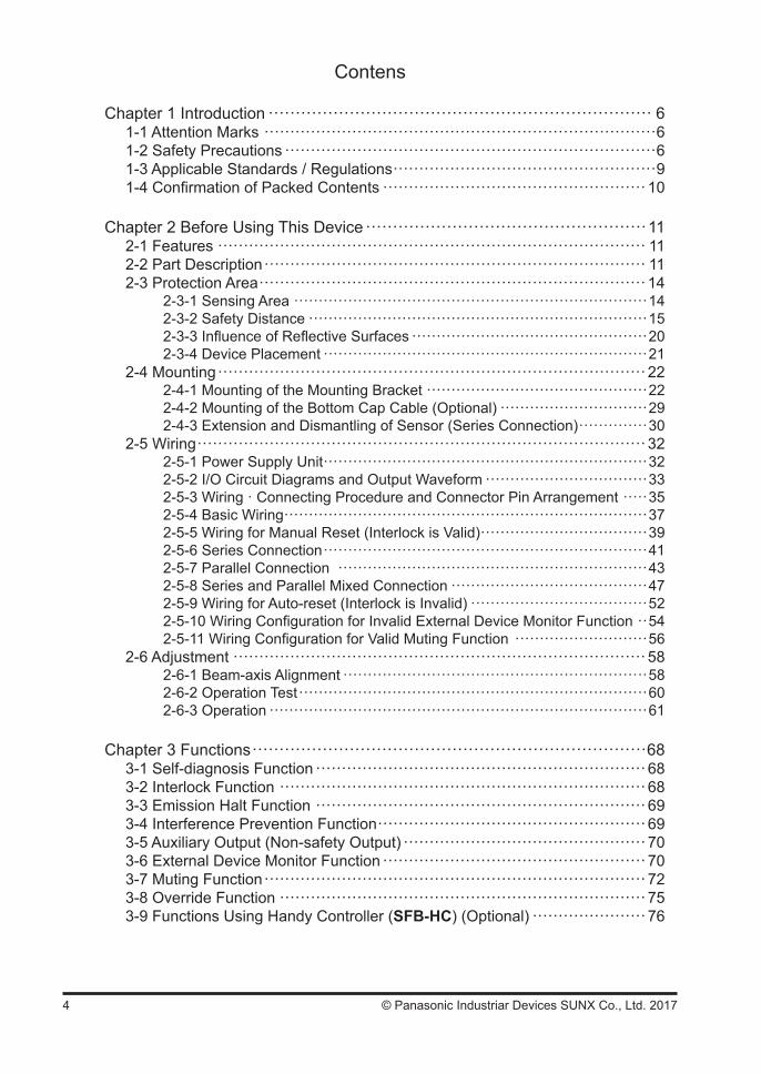
Contens
Chapter 1 Introduction ······································································· 61-1 Attention Marks ············································································61-2 Safety Precautions ········································································61-3 Applicable Standards / Regulations ···················································91-4 Confirmation of Packed Contents ···················································10
Chapter 2 Before Using This Device ····················································112-1 Features ··················································································· 112-2 Part Description ·········································································· 112-3 Protection Area ··········································································· 14
2-3-1 Sensing Area ········································································142-3-2 Safety Distance ·····································································152-3-3 Influence of Reflective Surfaces ················································202-3-4 Device Placement ··································································21
2-4 Mounting ··················································································· 222-4-1 Mounting of the Mounting Bracket ·············································222-4-2 Mounting of the Bottom Cap Cable (Optional) ······························292-4-3 Extension and Dismantling of Sensor (Series Connection) ··············30
2-5 Wiring ······················································································· 322-5-1 Power Supply Unit ··································································322-5-2 I/O Circuit Diagrams and Output Waveform ·································332-5-3 Wiring · Connecting Procedure and Connector Pin Arrangement ·····352-5-4 Basic Wiring ··········································································372-5-5 Wiring for Manual Reset (Interlock is Valid) ··································392-5-6 Series Connection ··································································412-5-7 Parallel Connection ·······························································432-5-8 Series and Parallel Mixed Connection ········································472-5-9 Wiring for Auto-reset (Interlock is Invalid) ····································522-5-10 Wiring Configuration for Invalid External Device Monitor Function ··542-5-11 Wiring Configuration for Valid Muting Function ···························56
2-6 Adjustment ················································································ 582-6-1 Beam-axis Alignment ······························································582-6-2 Operation Test ·······································································602-6-3 Operation ·············································································61
Chapter 3 Functions ·········································································683-1 Self-diagnosis Function ································································ 683-2 Interlock Function ······································································· 683-3 Emission Halt Function ································································693-4 Interference Prevention Function ····················································693-5 Auxiliary Output (Non-safety Output) ··············································· 703-6 External Device Monitor Function ··················································· 703-7 Muting Function ·········································································· 723-8 Override Function ······································································· 753-9 Functions Using Handy Controller (SFB-HC) (Optional) ······················ 76
5© Panasonic Industriar Devices SUNX Co., Ltd. 2017
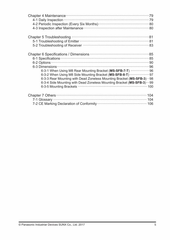
Chapter 4 Maintenance ·····································································794-1 Daily Inspection ··········································································794-2 Periodic Inspection (Every Six Months) ············································804-3 Inspection after Maintenance ························································· 80
Chapter 5 Troubleshooting ································································815-1 Troubleshooting of Emitter ···························································· 815-2 Troubleshooting of Receiver ························································· 83
Chapter 6 Specifications / Dimensions ·················································856-1 Specifications ·············································································856-2 Options ····················································································· 906-3 Dimensions················································································ 96
6-3-1 When Using M8 Rear Mounting Bracket (MS-SFB-7-T) ·················966-3-2 When Using M8 Side Mounting Bracket (MS-SFB-8-T) ··················976-3-3 Rear Mounting with Dead Zoneless Mounting Bracket (MS-SFB-3) ··986-3-4 Side Mounting with Dead Zoneless Mounting Bracket (MS-SFB-3) ···996-3-5 Mounting Brackets ······························································· 100
Chapter 7 Others ··········································································· 1047-1 Glossary ················································································· 1047-2 CE Marking Declaration of Conformity ··········································· 106
6 © Panasonic Industriar Devices SUNX Co., Ltd. 2017
Chapter 1 Introduction
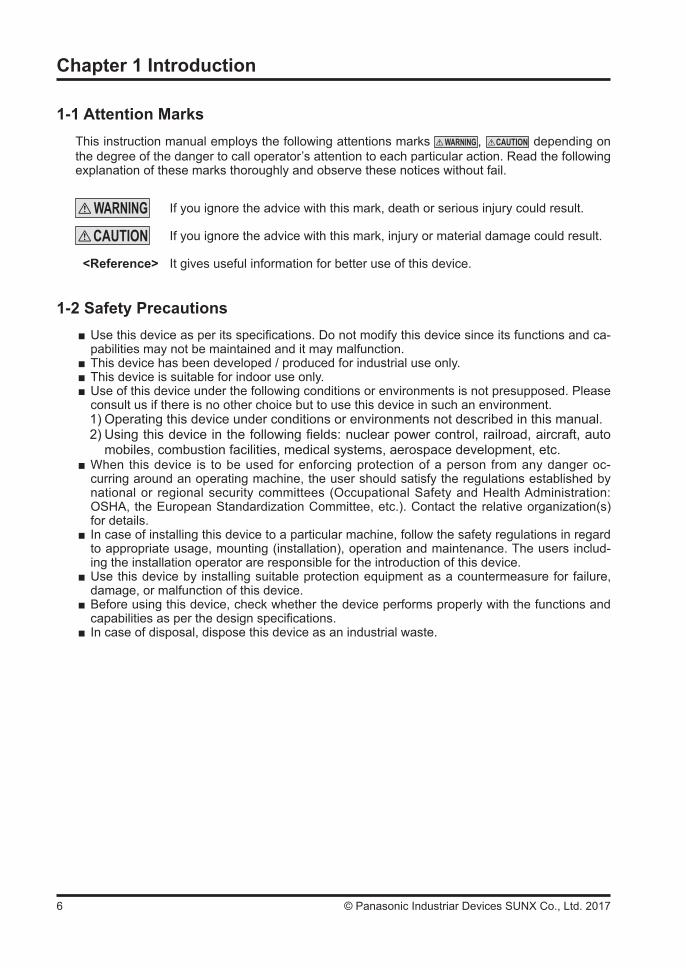
1-1 Attention MarksThis instruction manual employs the following attentions marks , depending on the degree of the danger to call operator’s attention to each particular action. Read the following explanation of these marks thoroughly and observe these notices without fail.
If you ignore the advice with this mark, death or serious injury could result.
If you ignore the advice with this mark, injury or material damage could result.
<Reference> It gives useful information for better use of this device.
1-2 Safety Precautions Use this device as per its specifications. Do not modify this device since its functions and ca-pabilities may not be maintained and it may malfunction.
This device has been developed / produced for industrial use only. This device is suitable for indoor use only. Use of this device under the following conditions or environments is not presupposed. Please consult us if there is no other choice but to use this device in such an environment. 1) Operating this device under conditions or environments not described in this manual.2) Using this device in the following fields: nuclear power control, railroad, aircraft, auto mobiles, combustion facilities, medical systems, aerospace development, etc.
When this device is to be used for enforcing protection of a person from any danger oc-curring around an operating machine, the user should satisfy the regulations established by national or regional security committees (Occupational Safety and Health Administration: OSHA, the European Standardization Committee, etc.). Contact the relative organization(s) for details.
In case of installing this device to a particular machine, follow the safety regulations in regard to appropriate usage, mounting (installation), operation and maintenance. The users includ-ing the installation operator are responsible for the introduction of this device.
Use this device by installing suitable protection equipment as a countermeasure for failure, damage, or malfunction of this device.
Before using this device, check whether the device performs properly with the functions and capabilities as per the design specifications.
In case of disposal, dispose this device as an industrial waste.
7© Panasonic Industriar Devices SUNX Co., Ltd. 2017
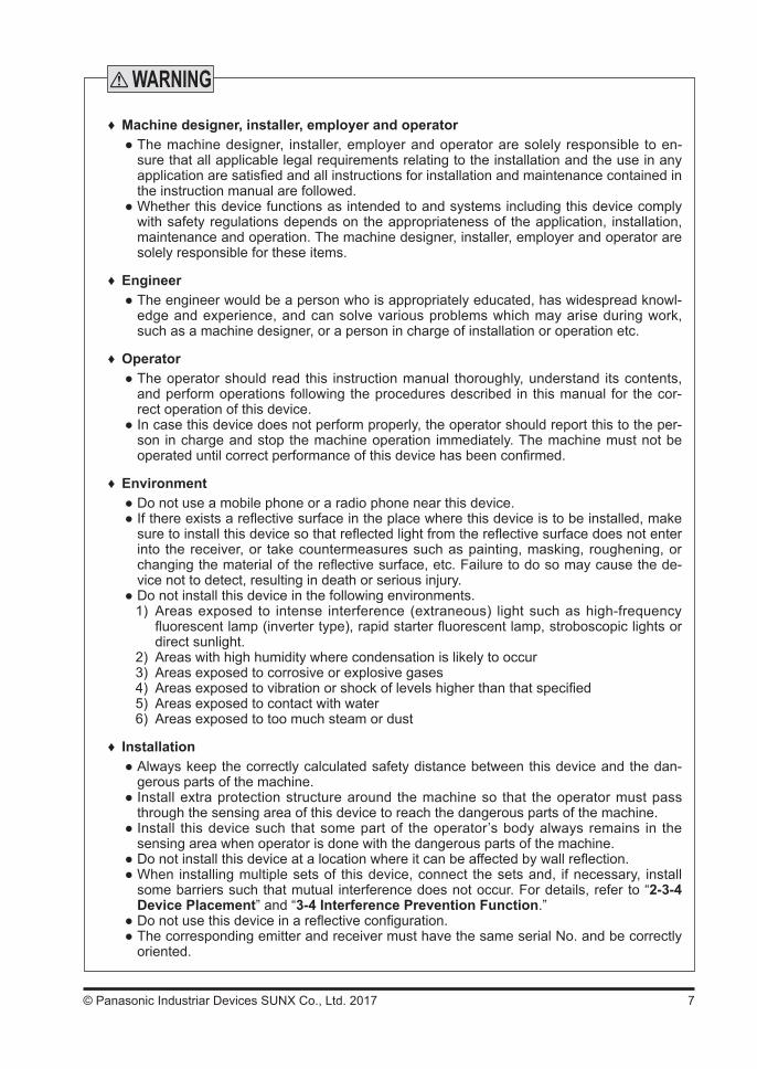
♦ Machine designer, installer, employer and operator The machine designer, installer, employer and operator are solely responsible to en-sure that all applicable legal requirements relating to the installation and the use in any application are satisfied and all instructions for installation and maintenance contained in the instruction manual are followed.
Whether this device functions as intended to and systems including this device comply with safety regulations depends on the appropriateness of the application, installation, maintenance and operation. The machine designer, installer, employer and operator are solely responsible for these items.
♦ Engineer The engineer would be a person who is appropriately educated, has widespread knowl-edge and experience, and can solve various problems which may arise during work, such as a machine designer, or a person in charge of installation or operation etc.
♦ Operator The operator should read this instruction manual thoroughly, understand its contents, and perform operations following the procedures described in this manual for the cor-rect operation of this device.
In case this device does not perform properly, the operator should report this to the per-son in charge and stop the machine operation immediately. The machine must not be operated until correct performance of this device has been confirmed.
♦ Environment Do not use a mobile phone or a radio phone near this device. If there exists a reflective surface in the place where this device is to be installed, make sure to install this device so that reflected light from the reflective surface does not enter into the receiver, or take countermeasures such as painting, masking, roughening, or changing the material of the reflective surface, etc. Failure to do so may cause the de-vice not to detect, resulting in death or serious injury.
Do not install this device in the following environments.1) Areas exposed to intense interference (extraneous) light such as high-frequency
fluorescent lamp (inverter type), rapid starter fluorescent lamp, stroboscopic lights or direct sunlight.
2) Areas with high humidity where condensation is likely to occur3) Areas exposed to corrosive or explosive gases4) Areas exposed to vibration or shock of levels higher than that specified5) Areas exposed to contact with water6) Areas exposed to too much steam or dust
♦ Installation Always keep the correctly calculated safety distance between this device and the dan-gerous parts of the machine.
Install extra protection structure around the machine so that the operator must pass through the sensing area of this device to reach the dangerous parts of the machine.
Install this device such that some part of the operator’s body always remains in the sensing area when operator is done with the dangerous parts of the machine.
Do not install this device at a location where it can be affected by wall reflection. When installing multiple sets of this device, connect the sets and, if necessary, install some barriers such that mutual interference does not occur. For details, refer to “2-3-4 Device Placement” and “3-4 Interference Prevention Function.”
Do not use this device in a reflective configuration. The corresponding emitter and receiver must have the same serial No. and be correctly oriented.
8 © Panasonic Industriar Devices SUNX Co., Ltd. 2017
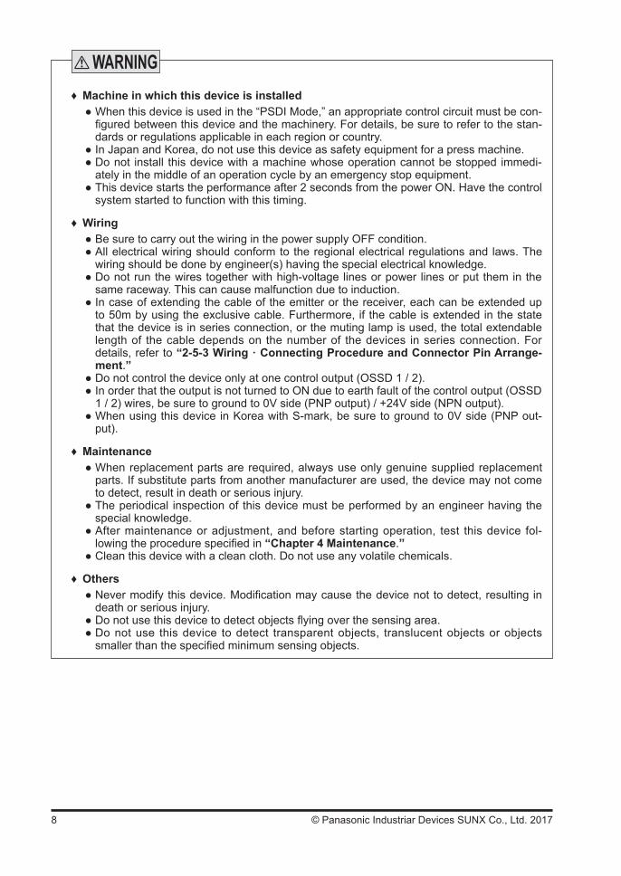
♦ Machine in which this device is installed When this device is used in the “PSDI Mode,” an appropriate control circuit must be con-figured between this device and the machinery. For details, be sure to refer to the stan-dards or regulations applicable in each region or country.
In Japan and Korea, do not use this device as safety equipment for a press machine. Do not install this device with a machine whose operation cannot be stopped immedi-ately in the middle of an operation cycle by an emergency stop equipment.
This device starts the performance after 2 seconds from the power ON. Have the control system started to function with this timing.
♦ Wiring Be sure to carry out the wiring in the power supply OFF condition. All electrical wiring should conform to the regional electrical regulations and laws. The wiring should be done by engineer(s) having the special electrical knowledge.
Do not run the wires together with high-voltage lines or power lines or put them in the same raceway. This can cause malfunction due to induction.
In case of extending the cable of the emitter or the receiver, each can be extended up to 50m by using the exclusive cable. Furthermore, if the cable is extended in the state that the device is in series connection, or the muting lamp is used, the total extendable length of the cable depends on the number of the devices in series connection. For details, refer to “2-5-3 Wiring · Connecting Procedure and Connector Pin Arrange-ment.”
Do not control the device only at one control output (OSSD 1 / 2). In order that the output is not turned to ON due to earth fault of the control output (OSSD 1 / 2) wires, be sure to ground to 0V side (PNP output) / +24V side (NPN output).
When using this device in Korea with S-mark, be sure to ground to 0V side (PNP out-put).
♦ Maintenance When replacement parts are required, always use only genuine supplied replacement parts. If substitute parts from another manufacturer are used, the device may not come to detect, result in death or serious injury.
The periodical inspection of this device must be performed by an engineer having the special knowledge.
After maintenance or adjustment, and before starting operation, test this device fol-lowing the procedure specified in “Chapter 4 Maintenance.”
Clean this device with a clean cloth. Do not use any volatile chemicals.
♦ Others Never modify this device. Modification may cause the device not to detect, resulting in death or serious injury.
Do not use this device to detect objects flying over the sensing area. Do not use this device to detect transparent objects, translucent objects or objects smaller than the specified minimum sensing objects.

9© Panasonic Industriar Devices SUNX Co., Ltd. 2017
1-3 Applicable Standards / RegulationsThis device complies with the following standards / regulations.<EU Directives>EU Machinery Directive 2006/42/ECEMC Directive 2014/30/EURoHS Directive 2011/65/EU
<European Standards>EN 61496-1 (Type 4), EN 55011, EN 61000-6-2, EN 50178EN ISO 13849-1: 2008 (Category 4, PLe)
<International Standards>IEC 61496-1/2 (Type 4), ISO 13849-1: 2006 (Category 4, PLe), IEC 61508-1~7 (SIL3)
<Japanese Industrial Standards (JIS)>JIS B 9704-1/2 (Type 4), JIS B 9705-1 (Category 4), JIS C 0508 (SIL3)
<Standards in US / Canada>ANSI/UL 61496-1/2 (Type 4), ANSI/UL 508, UL 1998 (Class 2)CAN/CSA C22.2 No.14, CAN/CSA C22.2 No.0.8
<Regulations in US>OSHA 1910.212, OSHA 1910.217(C), ANSI B11.1 to B11.19, ANSI/RIA 15.06
Regarding EU Machinery Directive, a Notified Body, TÜV SÜD, has certified with the type ex-amination certificate.With regard to the standards in US / Canada, a NRTL, UL (Underwriters Laboratories Inc.) has certified for CULUS Listing Mark.
<Regulations in China>GB 4584
<Regulations in Korea>S1-G-35-2005, S2-W-11-2003
The S-mark certificate has been certified by Korea Occupational Safety & Health Agency (KOSHA).
The conformity to JIS, OSHA and ANSI for this device has been evaluated by ourselves.The CULUS Listing Mark indicates compliance with both Canadian and US requirements.This device conforms to the EMC Directive and the Machinery Directive. The mark on the main body indicates that this device conforms to the EMC Directive.
mark makred on this divice shows that this divese has certified with the type examination certificate.
In Japan, never use this device as a safety equipment for any press machine or shearing machine.
When this device is used in a place other than the places shown above, be sure to confirm the standards or regulations applicable in each region or country be-fore use
<Reference>

10 © Panasonic Industriar Devices SUNX Co., Ltd. 2017
Before the use of this device, construct the control system that satisfies the following require-ments to secure the safety of the whole system.
To prevent the loss of the safety function due to a single fault.Always use two types of control output (OSSD 1 / 2).
To prevent the loss of the safety function due to the accumulation of the faults.Construct the control system that can stop a device if discrepancy between control out-puts (OSSD 1 / 2) is detected.<The example of the way to detect the discrepancy of control outputs>(Example 1) Use the relay unit or the controller for the light curtain. (Example 2) Monitor of the control outputs (OSSD 1 / 2) with the safety PLC. (Example 3) Monitor of the contact point welding in case the safety relay is used.
If one type of control output (OSSD) is used, the auxiliary output connects to PLC to moni-tor the operation of this device, and construct the control system that can stop a device if discrepancy between the control output (OSSD) and the auxiliary output is detected. It is possible to use another type of control output (OSSD) .
1-4 Confirmation of Packed Contents Sensor: Emitter, Receiver 1 pc. each Test Rod 1 pc.SF4B-F<V2>: SF4B-TR14 (ø14 × 220mm)SF4B-H<V2>: SF4B-TR25 (ø25 × 220mm)
Intermediate Supporting Bracket (MS-SFB-2) 0 to 3 setsNote: The intermediate support bracket (MS-SFB-2) is enclosed with the following devices. The quantity differs
depending on the device as shown below: 1 set: SF4B-F<V2> … 79 to 111 beam channels SF4B-H<V2> … 40 to 56 beam channels SF4B-A<V2> … 20 to 28 beam channels 2 sets: SF4B-F127<V2>, SF4B-H<V2> … 64 to 80 beam channels SF4B-A<V2> … 32 to 40 beam channels 3 sets: SF4B-H<V2> … 88 to 96 beam channels SF4B-A<V2> … 44 to 48 beam channels
Quick Instruction Manual 1 pc.
To use for Category 4 or 3
To use for Category 2
11© Panasonic Industriar Devices SUNX Co., Ltd. 2017
Chapter 2 Before Using This Device
2-1 FeaturesThis device is the light curtain with the following features.
No special controller is required. The control output (OSSD 1 / 2) is PNP / NPN output switching type. Beam-axis alignment indicators which make beam-axis alignment easy are incorporated. Each function setting is available by using the handy controller (SFB-HC) (optional). Refer to “3-9 Functions Using Handy Controller (SFB-HC) (Optional)” for details.
Refer to “6-2 Options” for details of options.
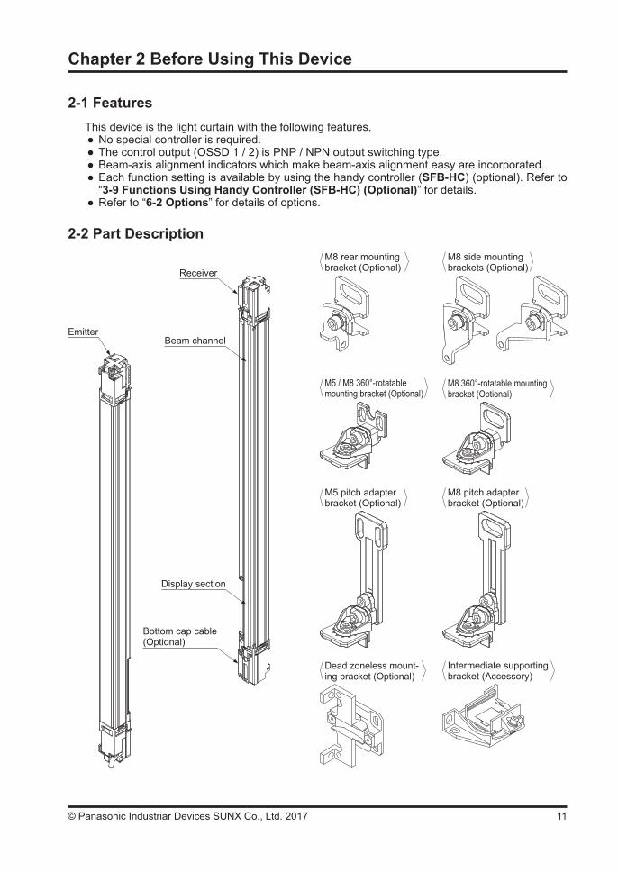
2-2 Part Description
EmitterBeam channel
Display section
Bottom cap cable(Optional)
Receiver
M8 rear mounting bracket (Optional)
M8 side mounting brackets (Optional)
M5 / M8 360°-rotatable mounting bracket (Optional)
M8 360°-rotatable mounting bracket (Optional)
M5 pitch adapter bracket (Optional)
M8 pitch adapter bracket (Optional)
Dead zoneless mount-ing bracket (Optional)
Intermediate supporting bracket (Accessory)

12 © Panasonic Industriar Devices SUNX Co., Ltd. 2017
<Emitter>It emits light to the receiver facing it. Furthermore, the status of the emitter and the receiver is indicated on its display section.
<Receiver>It receives light from the emitter facing it. Simultaneously, it turns ON the control output (OSSD 1 / 2) when the all beam channels receive light from emitter, and it turns OFF the control output (OSSD 1 / 2) when one or more beam channels are blocked light.[Exclude when using the muting function (Note 1) or the blanking function (Note 2).]Besides, the receiver displays its status on the display section.Notes: 1) In case of using the muting function, the following items, 12-core bottom cap cable (SFB-CB05-MU, SFB-CCB-MU) (optional), muting sensor and muting lamp are required. Please purchase 12-core bot-
tom cap cable, muting sensor, and muting lamp separately. 2) The blanking function is set by using the handy controller (SFB-HC) (optional). Please purchase the
handy controller separately.
<Beam channel>The light emitting elements of the emitter and the light receiving elements of the receiver are placed at the following intervals, 10mm (SF4B-F<V2>), 20mm (SF4B-H<V2>), and 40mm (SF4B-A<V2>).
<M8 rear mounting bracket (optional)>This bracket allows the emitter / receiver to be mounted at the rear with one M8 hexagon-socket head bolt. Horizontal angle can be adjusted.
<M8 side mounting bracket (optional)>This bracket allows the emitter / receiver to be mounted at the side with one M8 hexagon-socket head bolt. Horizontal angle can be adjusted.
<M5 / M8 360°-rotatable mounting bracket (optional)>This bracket is to be used for mounting the emitter / receiver. It is installed using two M5 hexa-gon-socket head bolts or one M8 hexagon-socket head bolt. 360° horizontal angle rotation can be done.
<M8 360°-rotatable mounting bracket (optional)>This bracket is to be used for mounting the emitter / receiver. It is installed using one M8 hexa-gon-socket head bolt. 360° horizontal angle rotation can be done.
<M5 pitch adapter bracket (optional)>This is used as the mounting bracket when changing over a previous light curtain with a sensing height of 200 to 750mm to this device. It is installed using two M5 hexagon-socket head bolts. 360° horizontal angle rotation can be done.
<M8 pitch adapter bracket (optional)>This is used as the mounting bracket when changing over a previous light curtain with a sensing height of 200 to 750mm to this device. It is installed using one M8 hexagon-socket head bolt. 360° horizontal angle rotation can be done.
<Dead zoneless mounting bracket (optional)>This bracket is to be used for mounting the emitter / receiver. This is useful for mounting the de-vice to the limited mounting space.
<Intermediate supporting bracket>This bracket is to be used for mounting the device having 79 beam channels or more for SF4B-F<V2>, 40 beam channels or more for SF4B-H<V2>, 20 beam channels or more for SF4B-A<V2>.
13© Panasonic Industriar Devices SUNX Co., Ltd. 2017
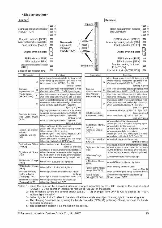
<Display section>
Description Function
Beam-axis alignment indicator(Red / Green)[RECEPTION]
A
When device top receives light: lights up in redWhen device top end receives light: blinks in redWhen control output (OSSD 1 / 2) is ON:
lights up in green
B When device upper middle receives light: lights up in redWhen control output (OSSD 1 / 2) is ON: lights up in green
C When device lower middle receives light: lights up in redWhen control output (OSSD 1 / 2) is ON: lights up in green
D
When device bottom receives light: lights up in redWhen device bottom end receives light: blinks in redWhen control output (OSSD 1 / 2) is ON:
lights up in green
Operator indicator(Red / Green) [OSSD](Note 1)
Lights up while device operation is as follows[sequential operation control output (OSSD1 / 2)]When control output (OSSD 1 / 2) is OFF:
lights up in redWhen control output (OSSD 1 / 2) is ON:
lights up in green
Incident light intensity indicator (Orange / Green)[STB.]
When sufficient light is received(Incident light: 130% or more) (Note 2): lights up in greenWhen stable light is received (Incident light: 115 to 130%) (Note 2): OFFWhen unstable light is received (Incident light : 100 to 115%) (Note 2): lights up in orangeWhen light is blocked: OFF (Note 3)
Fault indicator (Yellow)[FAULT]
When fault occurs in the device:lights up or blinks
Digital error indicator(Red)
When device is lockout, error contents are indicated.When the sensors are connected in paral-lel, the bottom of the digital error indicator on the slave side sensors lights up in red.
PNP indicator (Orange)[PNP] When PNP output is set: lights up
NPN indicator (Orange)[NPN] When NPN output is set: lights up
Emission intensity control indicator (Orange) [CTRL]
When light is emitted under short mode:lights up
When light is emitted under normal mode: OFFEmission halt indicator(Orange) [HALT]
When light emission is halt: lights upWhen light is emitted: OFF
Description Function
Beam-axis alignment indicator(Red / Green)[RECEPTION]
A
When device top receives light: lights up in redWhen device top end receives light: blinks in redWhen control output (OSSD 1 / 2) is ON:
lights up in green
B When device upper middle receives light: lights up in redWhen control output (OSSD 1 / 2) is ON: light up in green
C When device lower middle receives light: lights up in redWhen control output (OSSD 1 / 2) is ON: lights up in green
D
When device bottom receives light: lights up in redWhen device bottom end receives light: blinks in redWhen control output (OSSD 1 / 2) is ON:
lights up in green
OSSD indicator(Red / Green) [OSSD]
When control output (OSSD 1 / 2) is OFF:lights up in red
When control output (OSSD 1 / 2) is ON: lights up in green
Incident light intensity indicator (Orange / Green)[STB.]
When sufficient light is received(Incident light: 130% or more) (Note 2): lights up in greenWhen stable light is received (Incident light: 115 to 130%) (Note 2): OFFWhen unstable light is received (Incident light : 100 to 115%) (Note 2): lights up in orangeWhen light is blocked: OFF (Note 3)
Fault indicator (Yellow)[FAULT]
When fault occurs in the device:light up or blinks
Digital error indicator(Red)
When device is lockout, error contents are indicated.When the sensors are connected in paral-lel, the bottom of the digital error indicator on the slave side sensors lights up in red.
PNP indicator (Orange) [PNP] When PNP output is set: light up
NPN indicator (Orange)[NPN] When NPN output is set: lights up
Function setting indicator (orange) [FUNCTION]
When blanking function is used: lights up (Note 4)
When connecting the handy controller: brinksInterlock indicator(Yellow) [INTERLOCK]
When device is interlocked: lights upOther cases: OFF
Emitter Receiver
Incident light intensity indicator [STB.]
Digital error indicator
Beam-axis alignment indicator[RECEPTION]
Operation indicator [OSSD]
PNP indicator [PNP]NPN indicator[NPN]
Emission intensity control indicator[CTRL]
Emission halt indicator [HALT]
Fault indicator [FAULT]Beam-axis alignment indicator[RECEPTION]
Incident light intensity indicator [STB.]
Digital error indicator
Beam-axis alignment indicator[RECEPTION]
OSSD indicator [OSSD]
PNP indicator [PNP]NPN indicator [NPN]
Function setting indicator[FUNCTION]
Interlock indicator [INTERLOCK]
Fault indicator [FAULT]
Top end
Bottom end
Notes: 1) Since the color of the operation indicator changes according to ON / OFF status of the control output (OSSD 1 / 2), the operation indicator is marked as “OSSD” on the device.
2) The threshold where the control output (OSSD 1 / 2) changes from OFF to ON is applied as “100% incident light intensity”. 3) “When light is blocked” refers to the status that there exists any object blocking light in the sensing area. 4) The blanking function is set by using the handy controller (SFB-HC) (optional). Please purchase the handy controller separately. 5) The description given in [ ] is marked on the device.
14 © Panasonic Industriar Devices SUNX Co., Ltd. 2017
2-3 Protection Area2-3-1 Sensing Area
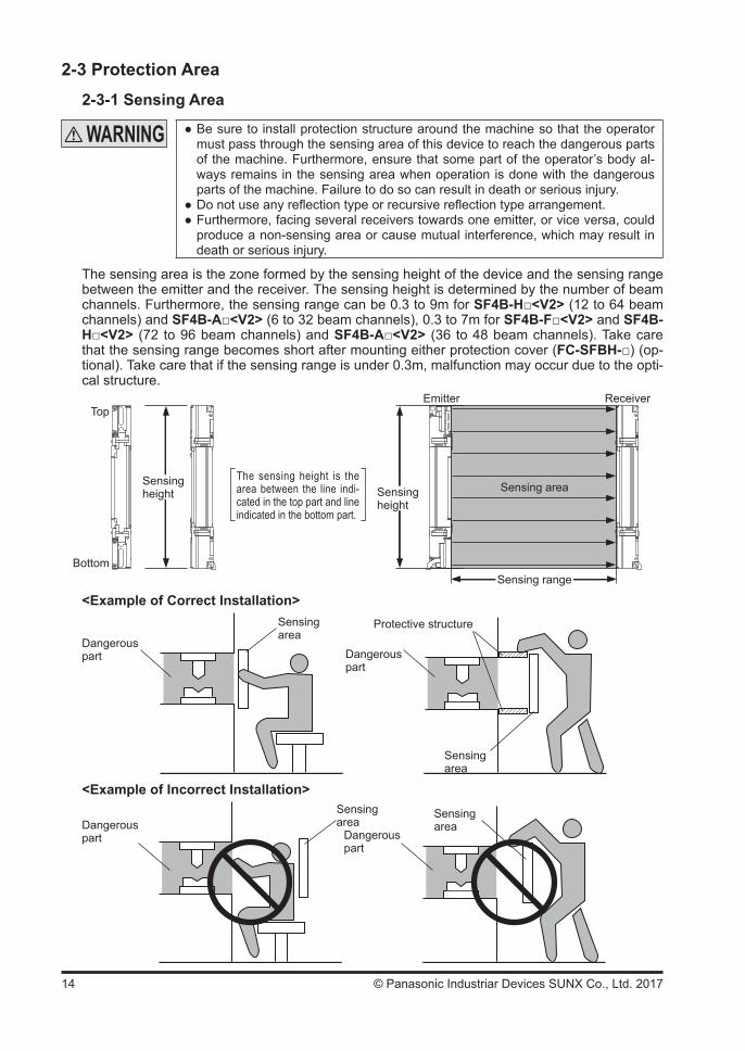
Be sure to install protection structure around the machine so that the operator must pass through the sensing area of this device to reach the dangerous parts of the machine. Furthermore, ensure that some part of the operator’s body al-ways remains in the sensing area when operation is done with the dangerous parts of the machine. Failure to do so can result in death or serious injury.
Do not use any reflection type or recursive reflection type arrangement. Furthermore, facing several receivers towards one emitter, or vice versa, could produce a non-sensing area or cause mutual interference, which may result in death or serious injury.
The sensing area is the zone formed by the sensing height of the device and the sensing range between the emitter and the receiver. The sensing height is determined by the number of beam channels. Furthermore, the sensing range can be 0.3 to 9m for SF4B-H<V2> (12 to 64 beam channels) and SF4B-A<V2> (6 to 32 beam channels), 0.3 to 7m for SF4B-F<V2> and SF4B-H<V2> (72 to 96 beam channels) and SF4B-A<V2> (36 to 48 beam channels). Take care that the sensing range becomes short after mounting either protection cover (FC-SFBH-) (op-tional). Take care that if the sensing range is under 0.3m, malfunction may occur due to the opti-cal structure.
Top
Bottom
Sensingheight
Emitter Receiver
Sensing area
Sensing range
The sensing height is the area between the line indi-cated in the top part and line indicated in the bottom part.
Sensingheight
<Example of Correct Installation>
Dangerous part
Sensingarea
Protective structure
Dangerous part
Sensingarea
<Example of Incorrect Installation>
Dangerous part
Sensingarea
Dangerous part
Sensingarea
15© Panasonic Industriar Devices SUNX Co., Ltd. 2017
2-3-2 Safety Distance
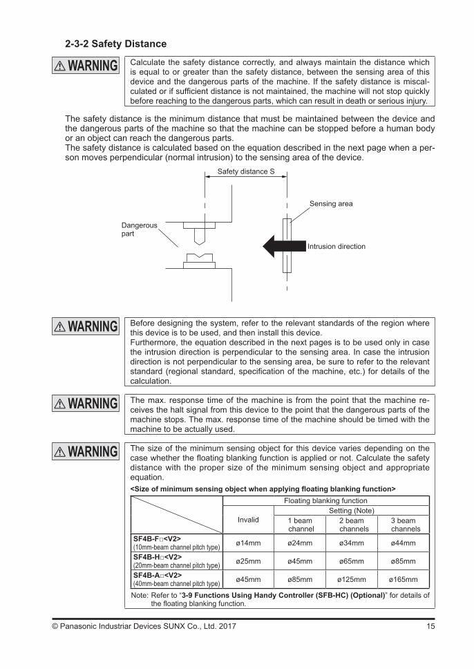
Calculate the safety distance correctly, and always maintain the distance which is equal to or greater than the safety distance, between the sensing area of this device and the dangerous parts of the machine. If the safety distance is miscal-culated or if sufficient distance is not maintained, the machine will not stop quickly before reaching to the dangerous parts, which can result in death or serious injury.
The safety distance is the minimum distance that must be maintained between the device and the dangerous parts of the machine so that the machine can be stopped before a human body or an object can reach the dangerous parts.The safety distance is calculated based on the equation described in the next page when a per-son moves perpendicular (normal intrusion) to the sensing area of the device.
Safety distance S
Sensing area
Intrusion direction
Dangerous part
Before designing the system, refer to the relevant standards of the region where this device is to be used, and then install this device.Furthermore, the equation described in the next pages is to be used only in case the intrusion direction is perpendicular to the sensing area. In case the intrusion direction is not perpendicular to the sensing area, be sure to refer to the relevant standard (regional standard, specification of the machine, etc.) for details of the calculation.
The max. response time of the machine is from the point that the machine re-ceives the halt signal from this device to the point that the dangerous parts of the machine stops. The max. response time of the machine should be timed with the machine to be actually used.
The size of the minimum sensing object for this device varies depending on the case whether the floating blanking function is applied or not. Calculate the safety distance with the proper size of the minimum sensing object and appropriate equation.<Size of minimum sensing object when applying floating blanking function>
Floating blanking function
InvalidSetting (Note)
1 beam channel
2 beam channels
3 beam channels
SF4B-F<V2>(10mm-beam channel pitch type) ø14mm ø24mm ø34mm ø44mm
SF4B-H<V2>(20mm-beam channel pitch type) ø25mm ø45mm ø65mm ø85mm
SF4B-A<V2>(40mm-beam channel pitch type) ø45mm ø85mm ø125mm ø165mm
Note: Refer to “3-9 Functions Using Handy Controller (SFB-HC) (Optional)” for details of the floating blanking function.
16 © Panasonic Industriar Devices SUNX Co., Ltd. 2017
[For use in Europe (EU) (as EN 999)] (Also applicable to ISO 13855)(For intrusion direction perpendicular to the sensing area)<In case that the minimum sensing object is ø40mm or less>
Equation 1 S = K × T + CS : Safety distance (mm) Minimum required distance between the sensing area surface and the danger-
ous parts of the machineK : Intrusion velocity of operator’s body or object (mm/sec.) Taken as 2,000 (mm/sec.) for calculationT : Response time of total equipment (sec.) T = Tm + TSF4B
Tm: Maximum halting time of machine (sec.) TSF4B: Response time of this device (sec.)C : Additional distance calculated from the size of the minimum sensing object of
the device (mm) However, the value of C cannot be under 0. C = 8 × (d - 14)
d: Minimum sensing object diameter (mm)
For calculating the safety distance S, there are the following five cases.First calculate by substituting the value K = 2,000 (mm/sec.) in the equation above. Then, classify the ob-tained value of S into three cases, 1) S < 100, 2) 100 ≤ S ≤ 500, and 3) S > 500.For Case 3) S > 500, recalculate by substituting the value K = 1,600 (mm/sec.). After that, classify the calculation result into two cases, 4) S ≤ 500 and 5) S > 500. For details, refer to “Calculation Example 1 For use in Europe.”
When this device is used in the “PSDI Mode,” an appropriate safety distance S must be calculated. For details, be sure to refer to the standards or regulations applicable in each region or country.
<In case that the minimum sensing object is over ø40mm> Equation S = K × T + C
S : Safety distance (mm) Minimum required distance between the sensing area surface and the danger-
ous parts of the machineK : Intrusion velocity of operator’s body or object (mm/sec.) Taken as 1,600 (mm/sec.) for calculationT : Response time of total equipment (sec.) T = Tm + TSF4B
Tm: Maximum halting time of machine (sec.)TSF4B: Response time of this device (sec.)
C : Additional distance calculated from the size of the minimum sensing object of the device (mm)
C = 850 (mm)
<Reference>
17© Panasonic Industriar Devices SUNX Co., Ltd. 2017
<Calculation Example> Calculation Example 1: For use in Europe(OFF response time: 14ms or less, minimum sensing object diameter: 14mm)
First, calculate with K = 2,000.S = K × T + C = K × (Tm + TSF4B) + 8 × (d - 14) = 2,000 × (Tm + 0.014) + 8 × (14 - 14) = 2,000 × Tm + 2,000 × 0.014 = 2,000 × Tm + 28If the result is:1) In case S < 100 (mm)
Safety distance S is taken as 100 (mm)2) In case 100 ≤ S ≤ 500 (mm)
Safety distance S is taken as 2,000 × Tm + 28 (mm)3) In case S > 500 (mm)
S = K’ × (Tm + TSF4B) + 8 × (d - 14) = 1,600 × (Tm + 0.014) + 8 × (14 - 14) = 1,600 × Tm + 1,600 × 0.014 = 1,600 × Tm + 22.4
then, calculate again.
If the result is:4) In case S ≤ 500 (mm)
Safety distance S is taken as 500 (mm)5) In case S > 500 (mm)
Safety distance S is taken as 1,600 × Tm + 22.4 (mm)
In case this device is installed in a system with a maximum halting time of 0.1 (sec.)S = 2,000 × Tm + 28
= 2,000 × 0.1 + 28= 228
Since this value matches with Case 2) above, S is 228 (mm).
In case this device is installed in a system with a maximum halting time of 0.4 (sec.)S = 2,000 × Tm + 28
= 2,000 × 0.4 + 28= 828
Since this value matches with Case 3) above,S = 1,600 × Tm + 22.4
= 1,600 × 0.4 + 22.4= 662.4
Since this value matches with Case 5) above, S is 662.4 (mm).

18 © Panasonic Industriar Devices SUNX Co., Ltd. 2017
[For use in the United States of America (as per ANSI B11.19)] Equation 2 Ds = K × (Ts + Tc + TSF4B + Tbm) + Dpf
Ds : Safety distance (mm) Minimum required distance between the sensing area surface and the danger-
ous parts of the machineK : Intrusion speed Recommended value in OSHA is 63 (inch/sec.) [≈ 1,600 (mm/sec.)] ANSI B11.19 does not define the intrusion speed “K”. When determining K, con-
sider possible factors including physical ability of operators.Ts : Halting time calculated from the operation time of the control element (air valve, etc.) (sec.)Tc : Maximum response time of the control circuit required for functioning the brake (sec.)TSF4B : Response time of this device (sec.) Tbm : Additional halting time tolerance for the brake monitor (sec.) The following equation holds when the machine is equipped with a brake monitor. Tbm = Ta - (Ts + Tc) Ta: Setting time of brake monitor (sec.) When the machine is not equipped with a brake monitor, it is recommended that
20% or more of (Ts + Tc) is taken as additional halting time. Dpf : Additional distance calculated from the size of the minimum sensing object of
the device (mm) SF4B-F<V2> Dpf = 23.8mm SF4B-H<V2> Dpf = 61.2mm SF4B-A<V2> Dpf = 129.2mm Dpf = 3.4 × (d - 0.276) (inch)
≈ 3.4 × (d - 7) (mm)d: Minimum sensing object diameter 0.552 (inch) ≈ 14 (mm) SF4B-F<V2>
Minimum sensing object diameter 0.985 (inch) ≈ 25 (mm) SF4B-H<V2>Minimum sensing object diameter 1.772 (inch) ≈ 45 (mm) SF4B-A<V2>
When the floating blanking function is applied, the minimum sensing object becomes large. According to ANSI B11.1, Dpf = 900mm (3ft) when d > 64mm (2.5 inches).
Since the calculation above is performed by taking 1 (inch) = 25.4 (mm), there is a slight difference be-tween the representation in (mm) and that in (inch). Refer to the relevant standard for the details.
<Calculation Example> Calculation Example 2 For use in the United States of America[OFF response time: 14ms or less, minimum sensing object diameter: 0.552 (inch) ≈ 14 (mm)]
Ds = K × (Ts + Tc + TSF4B + Tbm) + Dpf = 63 × (Ta + 0.014) + 3.4 × (d - 0.276) (inch) = 63 × (Ta + 0.014) + 3.4 × (0.552 - 0.276) = 63 × Ta + 63 x 0.014 + 3.4 × 0.276 = 63 × Ta + 1.8204 ≈ 63 × Ta + 1.82 (inch)In case this device is installed in a system with a maximum halting time 0.1 (sec.) Ds = 63 × Ta + 1.82 = 63 × 0.1 + 1.82 = 8.12 (inch) ≈ 206.248 (mm)Hence, as per the calculations Ds is 206.2 (mm).
Since the calculation above is performed by taking 1 (inch) = 25.4 (mm), there is a slight difference be-tween the representation in (mm) and that in (inch). Refer to the relevant standard for the details.
<Reference>
<Reference>
<Reference>

19© Panasonic Industriar Devices SUNX Co., Ltd. 2017
[In Chinese standard (GB 4584)]In case slide of press machine can be stopped where you would like to, safety distance S can be calculate by calculating formula 1.
Equation 1 S = K × T + CS : Safety distance (mm) Minimum required distance between the sensing area surface and the danger-
ous parts of the machine.K : Intrusion velocity of operator’s body or object (mm/sec.) In case the intrusion direction is horizontal to the sensing area, caluculate at 1,600
(mm/sec.). In case the intrusion direction is perpendicular to the sensing area, caluculate at 2,000 (mm/sec.) when the safety distance S ≤ 500mm and calcu-late at 1,600 (mm/sec.) when safety distance S > 500mm.
T : Response time of total equipment (sec.) T = Tm + TSF4B
Tm: Maximum halting time of machine (sec.) TSF4B: Response time of this device (sec.)C : Distance from entering hand to the sensing area to this product sensing it. (mm) Calculate based on table below in case not using interlock function (start-restart
interlock) of this device or safety controller in press machine.
Minimum sensing object Additional distance C Stroke starting by this device or safety controller etc.
≤ 14mm 0mmPossible> 14 to 20mm 80mm
> 20 to 30mm 130mm> 30 to 40mm 240mm
Not possible> 40mm 850mm
In case using interlock function (start-restart interlock) of this device or safety con-troller etc. in press machine, C equals 0.
In case the slide of press machine can not be stopped in your desire point, the safety distance S can be calculated from formula 2.
Equation 1 S = K × T + CS : Safety distance (mm) Minimum required distance between the sensing area surface and the danger-
ous parts of the machine.K : Intrusion velocity of operator’s body or object (mm/sec.) In case the intrusion direction is horizontal to the sensing area, caluculate at 1,600
(mm/sec.). In case the intrusion direction is perpendicular to the sensing area, caluculate at 2,000 (mm/sec.) when the safety distance S ≤ 500mm and calcu-late at 1,600 (mm/sec.) when safety distance S > 500mm.
TS : Time from entering hand to this device to slide reaching bottom dead point. (s) TS = [(1 / 2 ) + (1 / N)] × Tn N : Number of chases of clutch Tn : Time of going into a 360-degree roll (s)C : Distance from entering hand to the sensing area to this product sensing it. (mm) Calculate based on table below in case not using interlock function (start-restart
interlock) of this device or safety controller in press machine.
Minimum sensing object Additional distance C Stroke starting by this device or safety controller etc.
≤ 14mm 0mmPossible> 14 to 20mm 80mm
> 20 to 30mm 130mm> 30 to 40mm 240mm
Not possible> 40mm 850mm
In case using interlock function (start-restart interlock) of this device or safety con-troller etc. in press machine, C equals 0.
20 © Panasonic Industriar Devices SUNX Co., Ltd. 2017
2-3-3 Influence of Reflective Surfaces
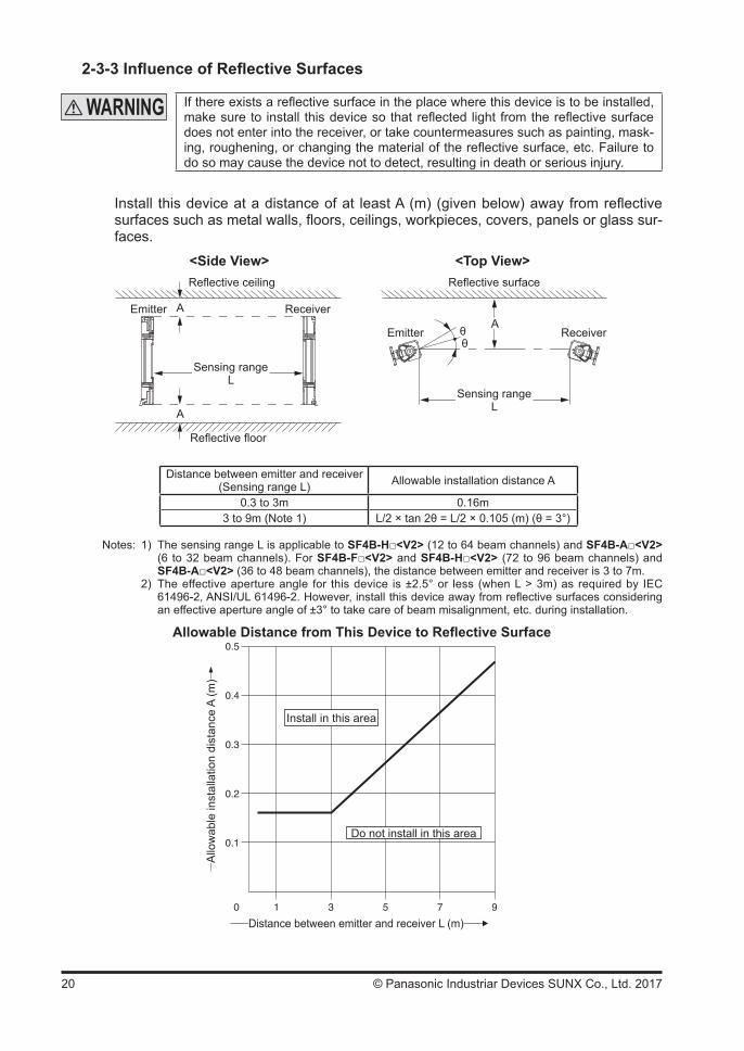
If there exists a reflective surface in the place where this device is to be installed, make sure to install this device so that reflected light from the reflective surface does not enter into the receiver, or take countermeasures such as painting, mask-ing, roughening, or changing the material of the reflective surface, etc. Failure to do so may cause the device not to detect, resulting in death or serious injury.
Install this device at a distance of at least A (m) (given below) away from reflective surfaces such as metal walls, floors, ceilings, workpieces, covers, panels or glass sur-faces.
<Side View>Reflective ceiling
Reflective floor
Emitter ReceiverA
A
Sensing rangeL
<Top View>Reflective surface
Emitter ReceiverA
Sensing rangeL
θθ
Distance between emitter and receiver (Sensing range L) Allowable installation distance A
0.3 to 3m 0.16m3 to 9m (Note 1) L/2 × tan 2θ = L/2 × 0.105 (m) (θ = 3°)
Notes: 1) The sensing range L is applicable to SF4B-H<V2> (12 to 64 beam channels) and SF4B-A<V2> (6 to 32 beam channels). For SF4B-F<V2> and SF4B-H<V2> (72 to 96 beam channels) and SF4B-A<V2> (36 to 48 beam channels), the distance between emitter and receiver is 3 to 7m.
2) The effective aperture angle for this device is ±2.5° or less (when L > 3m) as required by IEC 61496-2, ANSI/UL 61496-2. However, install this device away from reflective surfaces considering an effective aperture angle of ±3° to take care of beam misalignment, etc. during installation.
Allowable Distance from This Device to Reflective Surface
Allo
wab
le in
stal
latio
n di
stan
ce A
(m)
Install in this area
Do not install in this area
Distance between emitter and receiver L (m)
21© Panasonic Industriar Devices SUNX Co., Ltd. 2017
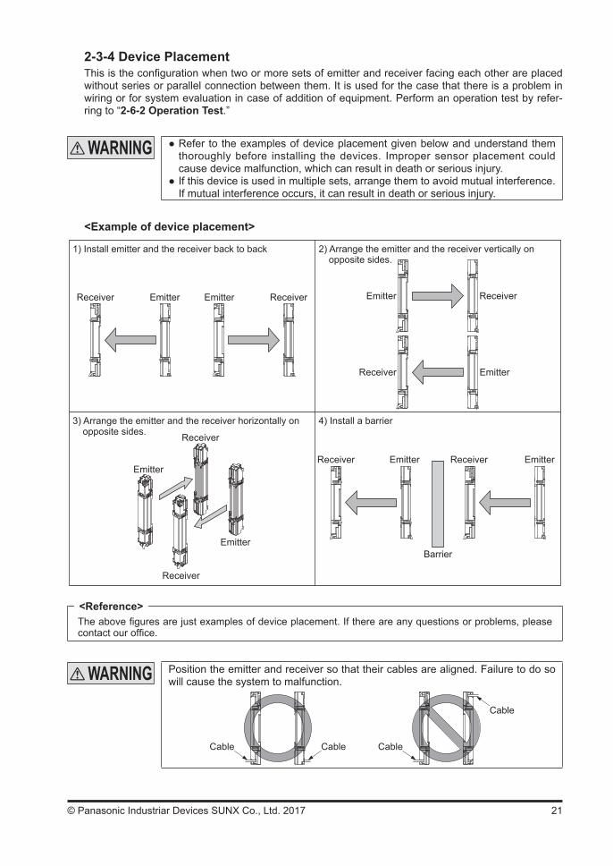
2-3-4 Device PlacementThis is the configuration when two or more sets of emitter and receiver facing each other are placed without series or parallel connection between them. It is used for the case that there is a problem in wiring or for system evaluation in case of addition of equipment. Perform an operation test by refer-ring to “2-6-2 Operation Test.”
Refer to the examples of device placement given below and understand them thoroughly before installing the devices. Improper sensor placement could cause device malfunction, which can result in death or serious injury.
If this device is used in multiple sets, arrange them to avoid mutual interference. If mutual interference occurs, it can result in death or serious injury.
<Example of device placement>
1) Install emitter and the receiver back to back
Receiver Emitter Emitter Receiver
2) Arrange the emitter and the receiver vertically onopposite sides.
Receiver
Emitter
Emitter
Receiver
3) Arrange the emitter and the receiver horizontally onopposite sides.
4) Install a barrier
Emitter
Receiver
Barrier
Receiver
Emitter
Emitter Receiver Emitter
Receiver
The above figures are just examples of device placement. If there are any questions or problems, please contact our office.
Position the emitter and receiver so that their cables are aligned. Failure to do so will cause the system to malfunction.
Cable CableCable
Cable
<Reference>
22 © Panasonic Industriar Devices SUNX Co., Ltd. 2017
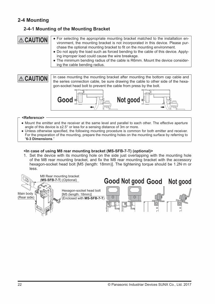
2-4 Mounting2-4-1 Mounting of the Mounting Bracket
For selecting the appropriate mounting bracket matched to the installation en-vironment, the mounting bracket is not incorporated in this device. Please pur-chase the optional mounting bracket to fit on the mounting environment.
Do not apply the load such as forced bending to the cable of this device. Apply-ing improper load could cause the wire breakage.
The minimum bending radius of the cable is R6mm. Mount the device consider-ing the cable bending radius.
In case mounting the mounting bracket after mounting the bottom cap cable and the series connection cable, be sure drawing the cable to other side of the hexa-gon-socket head bolt to prevent the cable from press by the bolt.
Good Not good
Mount the emitter and the receiver at the same level and parallel to each other. The effective aperture angle of this device is ±2.5° or less for a sensing distance of 3m or more.
Unless otherwise specified, the following mounting procedure is common for both emitter and receiver. For the preparation of the mounting, prepare the mounting holes on the mounting surface by referring to “6-3 Dimensions.”
<In case of using M8 rear mounting bracket (MS-SFB-7-T) (optional)>1. Set the device with its mounting hole on the side just overlapping with the mounting hole
of the M8 rear mounting bracket, and fix the M8 rear mounting bracket with the accessory hexagon-socket head bolt [M5 (length: 18mm)]. The tightening torque should be 1.2N·m or less.
Main body(Rear side)
Hexagon-socket head bolt[M5 (length: 18mm)]
Good Not good Good Not goodM8 Rear mounting bracket(MS-SFB-7-T) (Optional)
(Enclosed with MS-SFB-7-T)
<Reference>
23© Panasonic Industriar Devices SUNX Co., Ltd. 2017
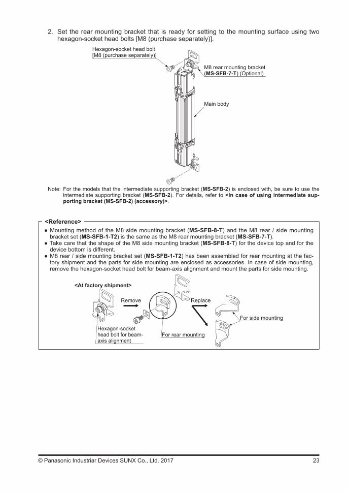
2. Set the rear mounting bracket that is ready for setting to the mounting surface using two hexagon-socket head bolts [M8 (purchase separately)].
Hexagon-socket head bolt[M8 (purchase separately)]
Main body
M8 rear mounting bracket(MS-SFB-7-T) (Optional)
Note: For the models that the intermediate supporting bracket (MS-SFB-2) is enclosed with, be sure to use the intermediate supporting bracket (MS-SFB-2). For details, refer to <In case of using intermediate sup-porting bracket (MS-SFB-2) (accessory)>.
Mounting method of the M8 side mounting bracket (MS-SFB-8-T) and the M8 rear / side mounting bracket set (MS-SFB-1-T2) is the same as the M8 rear mounting bracket (MS-SFB-7-T).
Take care that the shape of the M8 side mounting bracket (MS-SFB-8-T) for the device top and for the device bottom is different.
M8 rear / side mounting bracket set (MS-SFB-1-T2) has been assembled for rear mounting at the fac-tory shipment and the parts for side mounting are enclosed as accessories. In case of side mounting, remove the hexagon-socket head bolt for beam-axis alignment and mount the parts for side mounting.
Hexagon-socket head bolt for beam- axis alignment
For rear mounting
For side mounting
<At factory shipment>
Remove Replace
<Reference>
24 © Panasonic Industriar Devices SUNX Co., Ltd. 2017
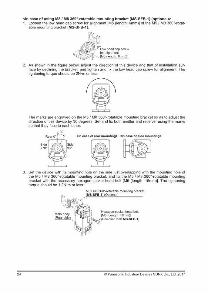
<In case of using M5 / M8 360°-rotatable mounting bracket (MS-SFB-1) (optional)>1. Loosen the low head cap screw for alignment [M5 (length: 6mm)] of the M5 / M8 360°-rotat-
able mounting bracket (MS-SFB-1).
Low head cap screwfor alignment[M5 (length: 6mm)]
2. As shown in the figure below, adjust the direction of this device and that of installation sur-face by declining the bracket, and tighten and fix the low head cap screw for alignment. The tightening torque should be 2N·m or less.
The marks are engraved on the M5 / M8 360°-rotatable mounting bracket so as to adjust the direction of this device by 30 degrees. Set and fix both emitter and receiver using the marks so that they face to each other.
Side270°
Side90°
Rear 0°30°
<In case of rear mounting> <In case of side mounting>
3. Set the device with its mounting hole on the side just overlapping with the mounting hole of the M5 / M8 360°-rotatable mounting bracket, and fix the M5 / M8 360°-rotatable mounting bracket with the accessory hexagon-socket head bolt [M5 (length: 16mm)]. The tightening torque should be 1.2N·m or less.
M5 / M8 360°-rotatable mounting bracket(MS-SFB-1) (Optional)
Main body(Rear side)
Hexagon-socket head bolt[M5 (Length: 16mm)](Enclosed with MS-SFB-1)
25© Panasonic Industriar Devices SUNX Co., Ltd. 2017
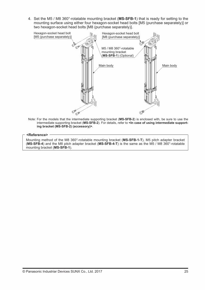
4. Set the M5 / M8 360°-rotatable mounting bracket (MS-SFB-1) that is ready for setting to the mounting surface using either four hexagon-socket head bolts [M5 (purchase separately)] or two hexagon-socket head bolts [M8 (purchase separately)].Hexagon-socket head bolt[M5 (purchase separately)]
Main body Main body
Hexagon-socket head bolt [M8 (purchase separately)]
M5 / M8 360°-rotatable mounting bracket(MS-SFB-1) (Optional)
Note: For the models that the intermediate supporting bracket (MS-SFB-2) is enclosed with, be sure to use the intermediate supporting bracket (MS-SFB-2). For details, refer to <In case of using intermediate support-ing bracket (MS-SFB-2) (accessory)>.
Mounting method of the M8 360°-rotatable mounting bracket (MS-SFB-1-T), M5 pitch adapter bracket (MS-SFB-4) and the M8 pitch adapter bracket (MS-SFB-4-T) is the same as the M5 / M8 360°-rotatable mounting bracket (MS-SFB-1).
<Reference>
26 © Panasonic Industriar Devices SUNX Co., Ltd. 2017
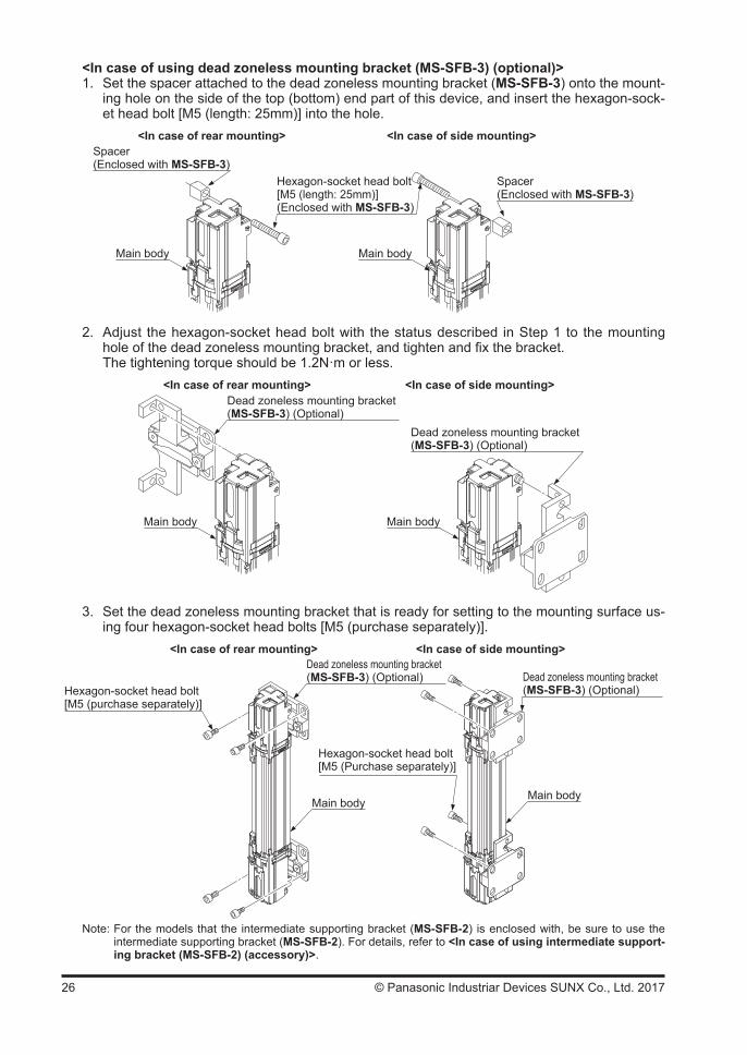
<In case of using dead zoneless mounting bracket (MS-SFB-3) (optional)>1. Set the spacer attached to the dead zoneless mounting bracket (MS-SFB-3) onto the mount-
ing hole on the side of the top (bottom) end part of this device, and insert the hexagon-sock-et head bolt [M5 (length: 25mm)] into the hole.
Main body
Spacer(Enclosed with MS-SFB-3)
Main body
Hexagon-socket head bolt[M5 (length: 25mm)](Enclosed with MS-SFB-3)
<In case of rear mounting> <In case of side mounting>Spacer(Enclosed with MS-SFB-3)
2. Adjust the hexagon-socket head bolt with the status described in Step 1 to the mounting hole of the dead zoneless mounting bracket, and tighten and fix the bracket.
The tightening torque should be 1.2N·m or less.
Main body Main body
Dead zoneless mounting bracket (MS-SFB-3) (Optional)
<In case of rear mounting> <In case of side mounting>
Dead zoneless mounting bracket (MS-SFB-3) (Optional)
3. Set the dead zoneless mounting bracket that is ready for setting to the mounting surface us-ing four hexagon-socket head bolts [M5 (purchase separately)].
Hexagon-socket head bolt [M5 (purchase separately)]
<In case of rear mounting> <In case of side mounting>Dead zoneless mounting bracket (MS-SFB-3) (Optional)
Hexagon-socket head bolt[M5 (Purchase separately)]
Main bodyMain body
Dead zoneless mounting bracket (MS-SFB-3) (Optional)
Note: For the models that the intermediate supporting bracket (MS-SFB-2) is enclosed with, be sure to use the intermediate supporting bracket (MS-SFB-2). For details, refer to <In case of using intermediate support-ing bracket (MS-SFB-2) (accessory)>.

27© Panasonic Industriar Devices SUNX Co., Ltd. 2017
<In case of using intermediate supporting bracket (MS-SFB-2) (accessory)>1. Loosen the hexagon-socket head bolt [M4 (length: 12mm)] screw of the intermediate sup-
porting bracket (MS-SFB-2).Hexagon-socket head bolt[M4 (Length: 12mm)]
2. Insert the side of this device into the intermediate supporting bracket, and fix it with the hexagon-socket head bolt [M4 (length: 12mm)]. The tightening torque should be 1.2N·m or less.
Refer to “6-3 Dimensions” for the mounting position of the intermediate supporting bracket.
Main body
Intermediate supporting bracket(MS-SFB-2) (Accessory)
Fit the pits and projectiles of both side surfaces of this device to those of both side inner surfaces of the intermediate supporting bracket.
When setting the intermediate supporting bracket on both side surfaces of this device, fit the four pits and projectiles of both side surfaces of the main body to those of both side surfaces (inner surfaces) of the intermediate supporting bracket.
3. After aligning the beam axis, mount the intermediate supporting bracket to the mounting sur-face using two hexagons-socket head bolts [M5 (purchase separately)].
For the details of beam-axis alignment, refer to “2-6-1 Beam-axis Alignment.” <In case of rear mounting>
Intermediate supporting bracket(MS-SFB-2) (Accesory)
<In case of side mounting>
Hexagon-socket head bolt[M5] (purchase separately)
Main bodyHexagon-socket head bolt [M5] (purchase separately)
Main body
Intermediate sup-porting bracket(MS-SFB-2)(Accesory)

28 © Panasonic Industriar Devices SUNX Co., Ltd. 2017
<Mounting protection bar set (MC-SFBH--T) (optional)>1. Mount the protection bar mounting bracket with the accessory two hexagon-socket head
bolts [M5 (length: 18mm)]. The tightening torque should be 1.2N·m or less.2. Mount the protection bar to the protection bar mounting bracket with a hexagon-socket head
bolt [M5 (length: 20mm)]. The tightening torque should be 3N·m or less.3. If the intermediate supporting bracket is used, mount the bracket with two hexagon-socket
bolts [M5 (purchase separately)] on the mounting surface temporarily. Furthermore, if the protection bar intermediate supporting bracket (MS-SFB-6) (optional) is used, also mount the bracket with a hexagon-socket bolt [M8 (purchase separately) on the mounting surface temporarily.
4. Mount the protection bar mounting bracket with a hexagon-socket bolt [M8 (purchase sepa-rately)] on the mounting surface temporarily.
5. Adjust the angle of the emitter and the receiver horizontally within the adjustable range of the elongate hole, and tighten the hexagon-socket bolt [M8 (purchase separately)].
6. Adjust the intermediate supporting bracket and protection bar intermediate supporting brack-et, and then tighten the hexagon-socket bolt [M8 (purchase separately)].
Hexagon-socket head bolt with washerM5 (Length: 20mm)
Protection mounting bracket
Protection bar
For rear mounting
Main body
Protection bar intermediate supporting bracketMS-SFB-6 (Optional)
Hexagon-socket head boltM5 (length: 18mm)
Protection bar mounting bracket has been assembled for rear mounting at the factory shipment and the parts for side mounting are enclosed as accessories. In case of side mounting, remove the hexagon-socket head bolt for beam-axis alignment and mount the parts for side mounting.
<At factory shipment>
Remove Replace
For rear mounting
For side mounting Hexagon-socket head bolt for beam-axis alignment
<Reference>
29© Panasonic Industriar Devices SUNX Co., Ltd. 2017
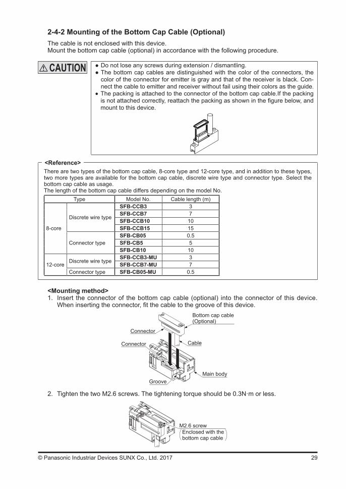
2-4-2 Mounting of the Bottom Cap Cable (Optional)The cable is not enclosed with this device.Mount the bottom cap cable (optional) in accordance with the following procedure.
Do not lose any screws during extension / dismantling. The bottom cap cables are distinguished with the color of the connectors, the color of the connector for emitter is gray and that of the receiver is black. Con-nect the cable to emitter and receiver without fail using their colors as the guide.
The packing is attached to the connector of the bottom cap cable.If the packing is not attached correctly, reattach the packing as shown in the figure below, and mount to this device.
There are two types of the bottom cap cable, 8-core type and 12-core type, and in addition to these types, two more types are available for the bottom cap cable, discrete wire type and connector type. Select the bottom cap cable as usage.The length of the bottom cap cable differs depending on the model No.
Type Model No. Cable length (m)
8-core
Discrete wire type
SFB-CCB3 3SFB-CCB7 7SFB-CCB10 10SFB-CCB15 15
Connector typeSFB-CB05 0.5SFB-CB5 5SFB-CB10 10
12-coreDiscrete wire type
SFB-CCB3-MU 3SFB-CCB7-MU 7
Connector type SFB-CB05-MU 0.5
<Mounting method>1. Insert the connector of the bottom cap cable (optional) into the connector of this device.
When inserting the connector, fit the cable to the groove of this device.
Connector
Bottom cap cable(Optional)
GrooveMain body
CableConnector
2. Tighten the two M2.6 screws. The tightening torque should be 0.3N·m or less.
M2.6 screwEnclosed with the bottom cap cable
<Reference>
30 © Panasonic Industriar Devices SUNX Co., Ltd. 2017
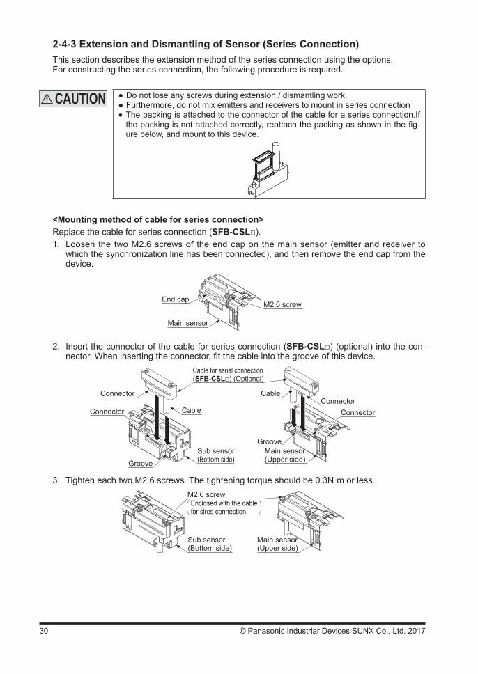
2-4-3 Extension and Dismantling of Sensor (Series Connection)This section describes the extension method of the series connection using the options.For constructing the series connection, the following procedure is required.
Do not lose any screws during extension / dismantling work. Furthermore, do not mix emitters and receivers to mount in series connection The packing is attached to the connector of the cable for a series connection.If the packing is not attached correctly, reattach the packing as shown in the fig-ure below, and mount to this device.
.
<Mounting method of cable for series connection>Replace the cable for series connection (SFB-CSL).1. Loosen the two M2.6 screws of the end cap on the main sensor (emitter and receiver to
which the synchronization line has been connected), and then remove the end cap from the device.
M2.6 screw
Main sensor
End cap
2. Insert the connector of the cable for series connection (SFB-CSL) (optional) into the con-nector. When inserting the connector, fit the cable into the groove of this device.
Connector
Groove
Cable
Connector Cable
Sub sensor(Bottom side)
Main sensor(Upper side)
Cable for serial connection(SFB-CSL) (Optional)
ConnectorConnector
Groove
3. Tighten each two M2.6 screws. The tightening torque should be 0.3N·m or less.
Sub sensor(Bottom side)
Main sensor(Upper side)
M2.6 screwEnclosed with the cable for sires connection
31© Panasonic Industriar Devices SUNX Co., Ltd. 2017
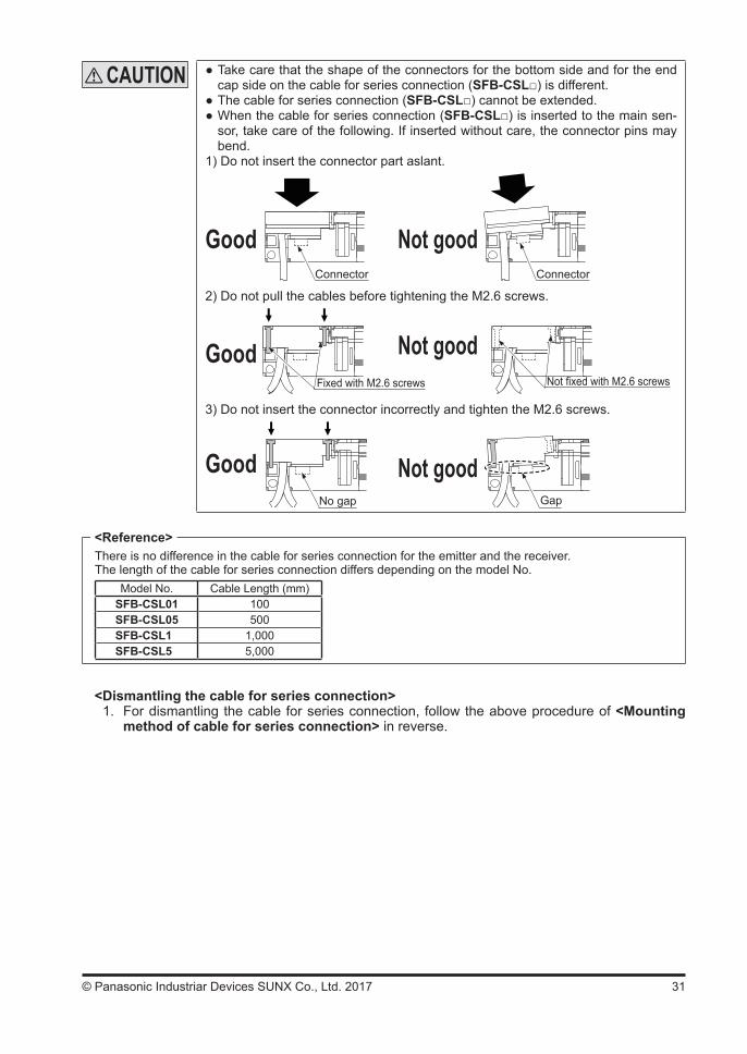
Take care that the shape of the connectors for the bottom side and for the end cap side on the cable for series connection (SFB-CSL) is different.
The cable for series connection (SFB-CSL) cannot be extended. When the cable for series connection (SFB-CSL) is inserted to the main sen-sor, take care of the following. If inserted without care, the connector pins may bend.
1) Do not insert the connector part aslant.
Connector Connector
Good Not good
2) Do not pull the cables before tightening the M2.6 screws.
GoodFixed with M2.6 screws Not fixed with M2.6 screws
Not good
3) Do not insert the connector incorrectly and tighten the M2.6 screws.
No gap
Good Not goodGap
There is no difference in the cable for series connection for the emitter and the receiver.The length of the cable for series connection differs depending on the model No.
Model No. Cable Length (mm)SFB-CSL01 100SFB-CSL05 500SFB-CSL1 1,000SFB-CSL5 5,000
<Dismantling the cable for series connection>1. For dismantling the cable for series connection, follow the above procedure of <Mounting
method of cable for series connection> in reverse.
<Reference>
32 © Panasonic Industriar Devices SUNX Co., Ltd. 2017
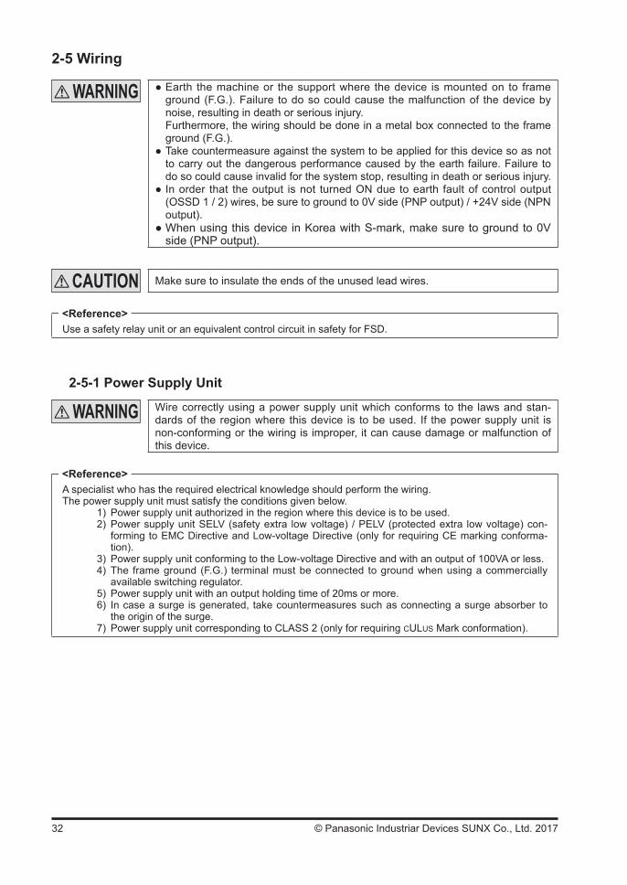
2-5 Wiring
Earth the machine or the support where the device is mounted on to frame ground (F.G.). Failure to do so could cause the malfunction of the device by noise, resulting in death or serious injury.Furthermore, the wiring should be done in a metal box connected to the frame ground (F.G.).
Take countermeasure against the system to be applied for this device so as not to carry out the dangerous performance caused by the earth failure. Failure to do so could cause invalid for the system stop, resulting in death or serious injury.
In order that the output is not turned ON due to earth fault of control output (OSSD 1 / 2) wires, be sure to ground to 0V side (PNP output) / +24V side (NPN output).
When using this device in Korea with S-mark, make sure to ground to 0V side (PNP output).
Make sure to insulate the ends of the unused lead wires.
Use a safety relay unit or an equivalent control circuit in safety for FSD.
2-5-1 Power Supply Unit
Wire correctly using a power supply unit which conforms to the laws and stan-dards of the region where this device is to be used. If the power supply unit is non-conforming or the wiring is improper, it can cause damage or malfunction of this device.
A specialist who has the required electrical knowledge should perform the wiring.The power supply unit must satisfy the conditions given below.
1) Power supply unit authorized in the region where this device is to be used.2) Power supply unit SELV (safety extra low voltage) / PELV (protected extra low voltage) con-
forming to EMC Directive and Low-voltage Directive (only for requiring CE marking conforma-tion).
3) Power supply unit conforming to the Low-voltage Directive and with an output of 100VA or less. 4) The frame ground (F.G.) terminal must be connected to ground when using a commercially
available switching regulator.5) Power supply unit with an output holding time of 20ms or more. 6) In case a surge is generated, take countermeasures such as connecting a surge absorber to
the origin of the surge.7) Power supply unit corresponding to CLASS 2 (only for requiring CULUS Mark conformation).
<Reference>
<Reference>
33© Panasonic Industriar Devices SUNX Co., Ltd. 2017
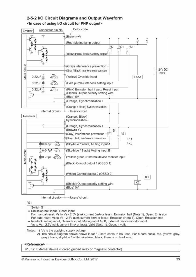
2-5-2 I/O Circuit Diagrams and Output Waveform<In case of using I/O circuit for PNP output>
Emitter
Mai
n ci
rcui
t
Receiver
(Brown) +V
(Gray) Interference prevention +(Gray / Black) Interference prevention -
(Pale purple) Interlock setting input
(Red) Muting lamp output
(Yellow-green / Black) Auxiliary output
(Shield) Output polarity setting wire(Blue) 0V(Orange) Synchronization +
(Orange / black) Synchronization -Users’ circuitInternal circuit
*S1
Load
+-
24V DC±10%
Color codeConnector pin No.
(Sky-blue / White) Muting input A
(Sky-blue / Black) Muting input B
(Yellow-green) External device monitor input
(Black) Control output 1 (OSSD 1)
(White) Control output 2 (OSSD 2)
(Blue) 0V
*S1
K1K2
K1
K2
(Yellow) Override input
(Pink) Emission halt input / Reset input
470Ω0.22μF
470Ω0.22μF
470Ω0.22μF
1kΩ0.047μF
1kΩ0.047μF
470Ω0.22μF
*S1 *S1
*S1
(Orange / Black)Synchronization -
(Orange) Synchronization +(Brown) +V(Gray) Interference prevention +(Gray / Black) Interference prevention -
Mai
n ci
rcui
t
(Shield) Output polarity setting wire
Users’ circuitInternal circuit
*S1Switch S1
Emission halt input / Reset inputFor manual reset: Vs to Vs - 2.5V (sink current 5mA or less) : Emission halt (Note 1), Open: EmissionFor auto-reset: Vs to Vs - 2.5V (sink current 5mA or less) : Emission (Note 1), Open: Emission halt
Interlock setting input, Override input, Muting input A / B, External device monitor inputVs to Vs - 2.5V (sink current 5mA or less): Valid (Note 1), Open: Invalid
Notes: 1) Vs is the applying supply voltage. 2) The circuit diagram shown above is for 12-core cable to be used. For 8-core cable, red, yellow, gray,
gray / black, sky-blue / white, sky-blue / black, there is no lead wire.
K1, K2: External device (Forced guided relay or magnetic contactor)<Reference>

34 © Panasonic Industriar Devices SUNX Co., Ltd. 2017
<In case of using I/O circuit for NPN output>
*S1
Load
+-
24V DC±10%
*S1K1K2
K2
K1
470Ω0.22μF
470Ω0.22μF
470Ω0.22μF
1kΩ0.047μF
1kΩ0.047μF
470Ω0.22μF
*S1 *S1
*S1
Emitter
Receiver
Connector pin No. Color codeM
ain
circ
uit
Mai
n ci
rcui
t
(Brown) +V
(Red) Muting lamp output
(Blue) 0V(Orange) Synchronization +
(Orange / black) Synchronization -
(Shield) Output polarity setting wire(Yellow) Override input
(Pale purple) Interlock setting input
(Pink) Emission halt input / Reset input
(Gray) Interference prevention +(Gray / Black) Interference prevention -
(Yellow-green / Black) Auxiliary output
Users’ circuitInternal circuit
Users’ circuitInternal circuit
(Sky-blue / White) Muting input A
(Sky-blue / Black) Muting input B
(Yellow-green) External device monitor input
(Black) Control output 1 (OSSD 1)
(White) Control output 2 (OSSD 2)
(Blue) 0V
(Orange) Synchronization +(Brown) +V
(Gray) Interference prevention +(Gray / Black) Interference prevention -
(Shield) Output polarity setting wire
(Orange / Black) Synchronization -
*S1Switch S1
Emission halt input / Reset inputFor manual reset: 0 to +1.5V (source current 5mA or less): Emission halt, Open: EmissionFor auto-reset: 0 to +1.5V (source current 5mA or less): Emission, Open: Emission halt
Interlock setting input, Override input, Muting input A / B, External device monitor input0 to + 1.5V (source current: 5mA or less): Valid, Open: Invalid
Note: The circuit diagram shown above is for 12-core cable to be used. For 8-core cable, red, yellow, gray, gray / black, sky-blue / white, sky-blue / black, there is no lead wire.
K1, K2: External device (Forced guided relay or magnetic contactor)<Reference>
35© Panasonic Industriar Devices SUNX Co., Ltd. 2017
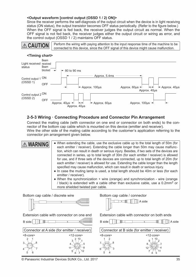
<Output waveform [control output (OSSD 1 / 2) ON]>Since the receiver performs the self-diagnosis of the output circuit when the device is in light receiving status (ON status), the output transistor becomes OFF status periodically. (Refer to the figure below.)When the OFF signal is fed back, the receiver judges the output circuit as normal. When the OFF signal is not fed back, the receiver judges either the output circuit or wiring as error, and the control output (OSSD 1 / 2) maintains OFF status.
Perform the wiring with paying attention to the input response time of the machine to be connected to this device, since the OFF signal of this device might cause malfunction.
<Timing chart>BeamreceivedBeamblocked
Light received status
ON
OFF
ON
OFF
80 to 90 ms
Approx. 5.4ms
Approx. 40μs
Control output 2(OSSD 2)
Approx. 60μsApprox. 40μs
Approx. 60μs Approx. 40μsApprox. 40μs
Approx. 100μs
Control output 1 (OSSD 1)
Approx. 100μs
2-5-3 Wiring · Connecting Procedure and Connector Pin ArrangementConnect the mating cable (with connector on one end or connector on both ends) to the con-nector of the bottom cap cable which is mounted on this device (emitter and receiver).Wire the other side of the mating cable according to the customer’s application referring to the connector pin arrangement given below.
When extending the cable, use the exclusive cable up to the total length of 50m (for each emitter / receiver). Extending the cable longer than 50m may cause malfunc-tion, which can result in death or serious injury. Besides, if two sets of the devices are connected in series, up to total length of 30m (for each emitter / receiver) is allowed for use, and if three sets of the devices are connected, up to total length of 20m (for each emitter / receiver) is allowed for use. Extending the cable longer than the length specified may cause malfunction, which can result in death or serious injury.
In case the muting lamp is used, a total length should be 40m or less (for each emitter / receiver).
When the synchronization + wire (orange) and synchronization - wire (orange / black) is extended with a cable other than exclusive cable, use a 0.2mm2 or more shielded twisted pair cable.
Connector at A side (for emitter / receiver) Connector at B side (for emitter / receiver)
A sideB side
<8-core> <12-core> <8-core> <12-core>
A side
Bottom cap cable / discrete wire Bottom cap cable / connector
Extension cable with connector on one end Extension cable with connector on both ends
B side

36 © Panasonic Industriar Devices SUNX Co., Ltd. 2017
<8-core cable (SFB-CC )>
Cable / connector color Connector Pin No. Color code Description
Emitter Gray / Gray
1 Pale purple Interlock setting input2 Brown +V3 Pink Emission halt input / Reset input4 Yellow-green / Black Auxiliary output5 Orange Synchronization +6 Orange / Black Synchronization -7 Blue 0V8 (Shield) Output polarity setting wire
Receiver Gray (with black stripe)/Black
1 White Control output 2 (OSSD 2)2 Brown +V3 Black Control output 1 (OSSD 1)4 Yellow-green External device monitor input5 Orange Synchronization +6 Orange / Black Synchronization -7 Blue 0V8 (Shield) Output polarity setting wire
<12-core cable (SFB-CC-MU )>
Cable / connector color Connector Pin No.. Color code Description
Emitter Gray / Gray
1 Pale purple Interlock setting input2 Brown +V3 Pink Emission halt input / Reset input4 Yellow-green / Black Auxiliary output5 Orange Synchronization +6 Orange / Black Synchronization -7 Blue 0V8 (Shield) Output polarity setting wire9 Gray Interference prevention +
10 Gray / Black Interference prevention -11 Yellow Override input12 Red Muting lamp output
Receiver Gray (with black stripe) / Black
1 White Control output 2 (OSSD 2)2 Brown +V3 Black Control output 1 (OSSD 1)4 Yellow-green External device monitor input5 Orange Synchronization +6 Orange / Black Synchronization -7 Blue 0V8 (Shield) Output polarity setting wire9 Gray Interference prevention +
10 Gray / Black Interference prevention -11 Sky-blue / White Muting input A12 Sky-blue / Black Muting input B
The connectors can be distinguished from their colors as follows:Connector for emitter: gray, connector for receiver: black
For details of the bottom cap cable, the cable with connector on one end, and the cable with connector on both ends, refer to “6-2 Options.”
<Reference>
37© Panasonic Industriar Devices SUNX Co., Ltd. 2017
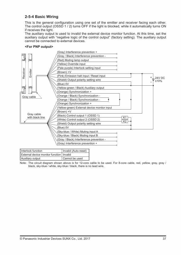
2-5-4 Basic WiringThis is the general configuration using one set of the emitter and receiver facing each other. The control output (OSSD 1 / 2) turns OFF if the light is blocked, while it automatically turns ON if receives the light.The auxiliary output is used to invalid the external device monitor function. At this time, set the auxiliary output with “negative logic of the control output” (factory setting). The auxiliary output cannot be connected to external devices.
<For PNP output>
K1
+ 24V DC±10%-
Em
itter
Rec
eive
r
Gray cable
Gray cable with black line
K2
(Brown) +V(Pale purple) Interlock setting input
(Yellow-green / Black) Auxiliary output
(Gray) Interference prevention +(Gray / Black) Interference prevention -(Red) Muting lamp output
(Pink) Emission halt input / Reset input(Shield) Output polarity setting wire(Blue) 0V
(Yellow) Override input
(Orange) Synchronization +(Orange / Black) Synchronization -
(Orange) Synchronization +(Orange / Black) Synchronization -
(Yellow-green) External device monitor input(Brown) +V(Black) Control output 1 (OSSD 1)(White) Control output 2 (OSSD 2)(Shield) Output polarity setting wire(Blue) 0V(Sky-blue / White) Muting input A(Sky-blue / Black) Muting input B(Gray / Black) Interference prevention -(Gray) Interference prevention +
Interlock function Invalid (Auto-reset)External device monitor function InvalidAuxiliary output Cannot be used
Note: The circuit diagram shown above is for 12-core cable to be used. For 8-core cable, red, yellow, gray, gray / black, sky-blue / white, sky-blue / black, there is no lead wire.
38 © Panasonic Industriar Devices SUNX Co., Ltd. 2017
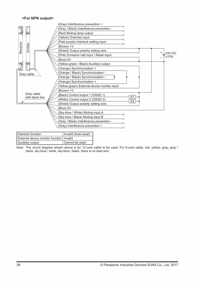
<For NPN output>
K1K2
Gray cable
+ 24V DC±10%-
Em
itter
Rec
eive
r
(Shield) Output polarity setting wire
(Blue) 0V
(Brown) +V(Pale purple) Interlock setting input
(Gray) Interference prevention +(Gray / Black) Interference prevention -(Red) Muting lamp output(Yellow) Override input
(Yellow-green) External device monitor input(Brown) +V
(Shield) Output polarity setting wire
(Sky-blue / White) Muting input A(Sky-blue / Black) Muting input B(Gray / Black) Interference prevention -(Gray) Interference prevention +
(Pink) Emission halt input / Reset input
(Yellow-green / Black) Auxiliary output(Blue) 0V
(Orange) Synchronization +(Orange / Black) Synchronization -
(Orange) Synchronization +(Orange / Black) Synchronization -
Gray cable with black line
(Black) Control output 1 (OSSD 1)(White) Control output 2 (OSSD 2)
Interlock function Invalid (Auto-reset)External device monitor function InvalidAuxiliary output Cannot be used
Note: The circuit diagram shown above is for 12-core cable to be used. For 8-core cable, red, yellow, gray, gray / black, sky-blue / white, sky-blue / black, there is no lead wire.
39© Panasonic Industriar Devices SUNX Co., Ltd. 2017
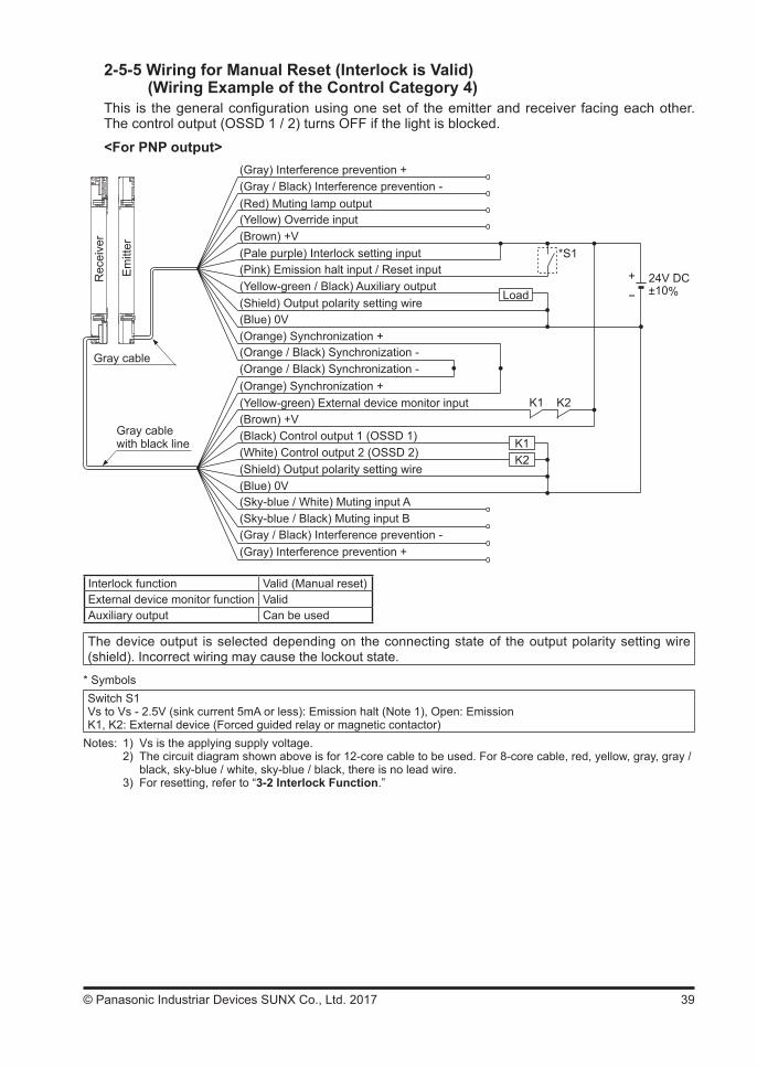
2-5-5 Wiring for Manual Reset (Interlock is Valid)(Wiring Example of the Control Category 4)
This is the general configuration using one set of the emitter and receiver facing each other. The control output (OSSD 1 / 2) turns OFF if the light is blocked.
<For PNP output>
+ 24V DC±10%-
K1K2
Load
*S1
K1 K2
Em
itter
Rec
eive
r
Gray cable
Gray cable with black line
(Shield) Output polarity setting wire
(Blue) 0V
(Brown) +V(Pale purple) Interlock setting input
(Gray) Interference prevention +(Gray / Black) Interference prevention -(Red) Muting lamp output(Yellow) Override input
(Yellow-green) External device monitor input(Brown) +V
(Shield) Output polarity setting wire
(Sky-blue / White) Muting input A(Sky-blue / Black) Muting input B(Gray / Black) Interference prevention -(Gray) Interference prevention +
(Pink) Emission halt input / Reset input(Yellow-green / Black) Auxiliary output
(Blue) 0V(Orange) Synchronization +(Orange / Black) Synchronization -
(Orange) Synchronization +(Orange / Black) Synchronization -
(Black) Control output 1 (OSSD 1)(White) Control output 2 (OSSD 2)
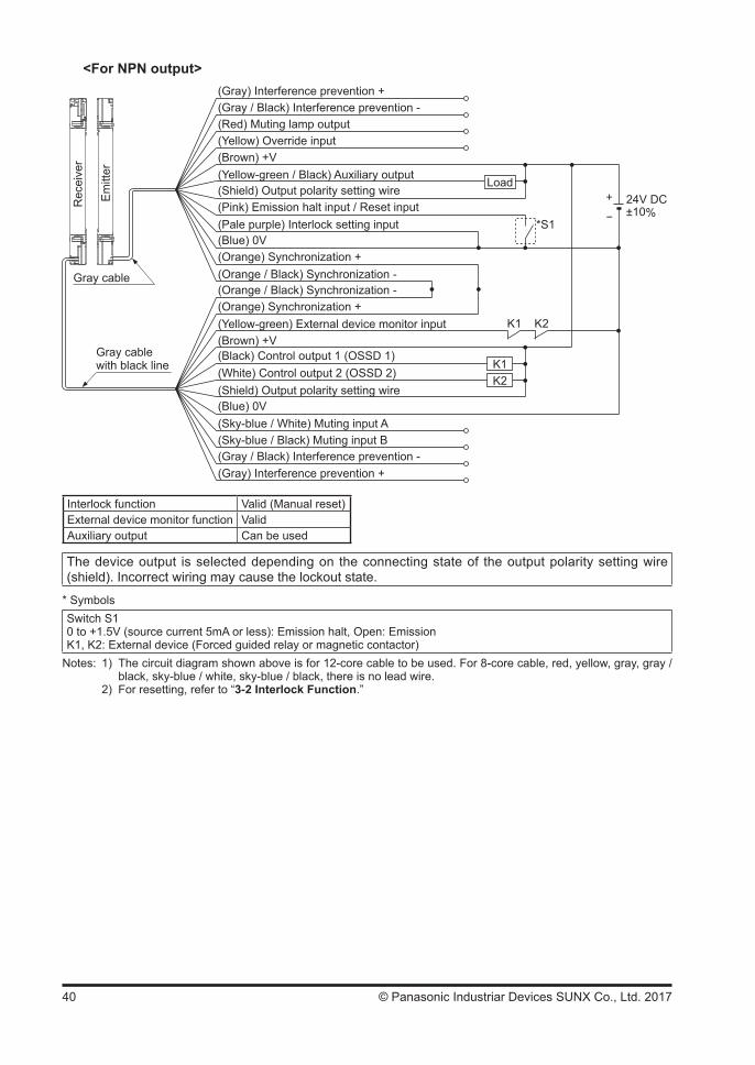
Interlock function Valid (Manual reset)External device monitor function ValidAuxiliary output Can be used
The device output is selected depending on the connecting state of the output polarity setting wire (shield). Incorrect wiring may cause the lockout state.
* SymbolsSwitch S1Vs to Vs - 2.5V (sink current 5mA or less): Emission halt (Note 1), Open: EmissionK1, K2: External device (Forced guided relay or magnetic contactor)
Notes: 1) Vs is the applying supply voltage. 2) The circuit diagram shown above is for 12-core cable to be used. For 8-core cable, red, yellow, gray, gray / black, sky-blue / white, sky-blue / black, there is no lead wire. 3) For resetting, refer to “3-2 Interlock Function.”
40 © Panasonic Industriar Devices SUNX Co., Ltd. 2017
<For NPN output>
+ 24V DC±10%-
K1K2
Load
*S1
K1 K2
(Shield) Output polarity setting wire
(Blue) 0V
(Brown) +V
(Pale purple) Interlock setting input
(Gray) Interference prevention +(Gray / Black) Interference prevention -(Red) Muting lamp output(Yellow) Override input
(Yellow-green) External device monitor input(Brown) +V
(Shield) Output polarity setting wire
(Sky-blue / White) Muting input A(Sky-blue / Black) Muting input B(Gray / Black) Interference prevention -(Gray) Interference prevention +
(Pink) Emission halt input / Reset input
(Yellow-green / Black) Auxiliary output
(Blue) 0V(Orange) Synchronization +(Orange / Black) Synchronization -
(Orange) Synchronization +(Orange / Black) Synchronization -
Gray cable
Gray cable with black line
(Black) Control output 1 (OSSD 1)(White) Control output 2 (OSSD 2)
Em
itter
Rec
eive
r
Interlock function Valid (Manual reset)External device monitor function ValidAuxiliary output Can be used
The device output is selected depending on the connecting state of the output polarity setting wire (shield). Incorrect wiring may cause the lockout state.
* SymbolsSwitch S10 to +1.5V (source current 5mA or less): Emission halt, Open: EmissionK1, K2: External device (Forced guided relay or magnetic contactor)
Notes: 1) The circuit diagram shown above is for 12-core cable to be used. For 8-core cable, red, yellow, gray, gray / black, sky-blue / white, sky-blue / black, there is no lead wire.
2) For resetting, refer to “3-2 Interlock Function.”

41© Panasonic Industriar Devices SUNX Co., Ltd. 2017
2-5-6 Series Connection(Wiring Example of the Control Category 4)
[Connectable up to 3 sets of the devices (however, 192 beam channels max.)]This is the configuration for connecting multiple sets of emitters and receivers facing each other in series. It is used when the dangerous part can be entered from two or more directions. If any of the sets is in light blocked status, the control output (OSSD 1 / 2) turns OFF.
For series connection, connect the emitter and emitter, receiver and receiver re-spectively using the exclusive cable (SFB-CSL) for series connection. Wrong con-nection could generate the non-sensing area, resulting in death or serious injury.
<For PNP output>
+ 24V DC±10%-Re
ceive
r 2 s
ub s
enso
r
Emitt
er 2
sub
sen
sor
K1K2
Load
*S1
K1 K2
Rece
iver 1
main
sens
or
Emitt
er 1
mai
n se
nsor
Gray cable
Gray cable with black line
(Shield) Output polarity setting wire
(Blue) 0V
(Brown) +V(Pale purple) Interlock setting input
(Gray) Interference prevention +(Gray / Black) Interference prevention -(Red) Muting lamp output(Yellow) Override input
(Yellow-green) External device monitor input(Brown) +V
(Shield) Output polarity setting wire
(Sky-blue / White) Muting input A(Sky-blue / Black) Muting input B(Gray / Black) Interference prevention -(Gray) Interference prevention +
(Pink) Emission halt input / Reset input(Yellow-green / Black) Auxiliary output
(Blue) 0V(Orange) Synchronization +(Orange / Black) Synchronization -
(Orange) Synchronization +(Orange / Black) Synchronization -
(Black) Control output 1 (OSSD 1)(White) Control output 2 (OSSD 2)
Interlock function Valid (Manual reset)External device monitor function ValidAuxiliary output Can be used
The device output is selected depending on the connecting state of the output polarity setting wire (shield). Incorrect wiring may cause the lockout state.
* SymbolsSwitch S1Vs to Vs - 2.5V (sink current 5mA or less): Emission halt (Note 1), Open: EmissionK1, K2: External device (Forced guided relay or magnetic contactor)
Notes: 1) Vs is the applying supply voltage. 2) The circuit diagram shown above is for 12-core cable to be used. For 8-core cable, red, yellow, gray, gray / black, sky-blue / white, sky-blue / black, there is no lead wire. 3) For resetting, refer to “3-2 Interlock Function.”
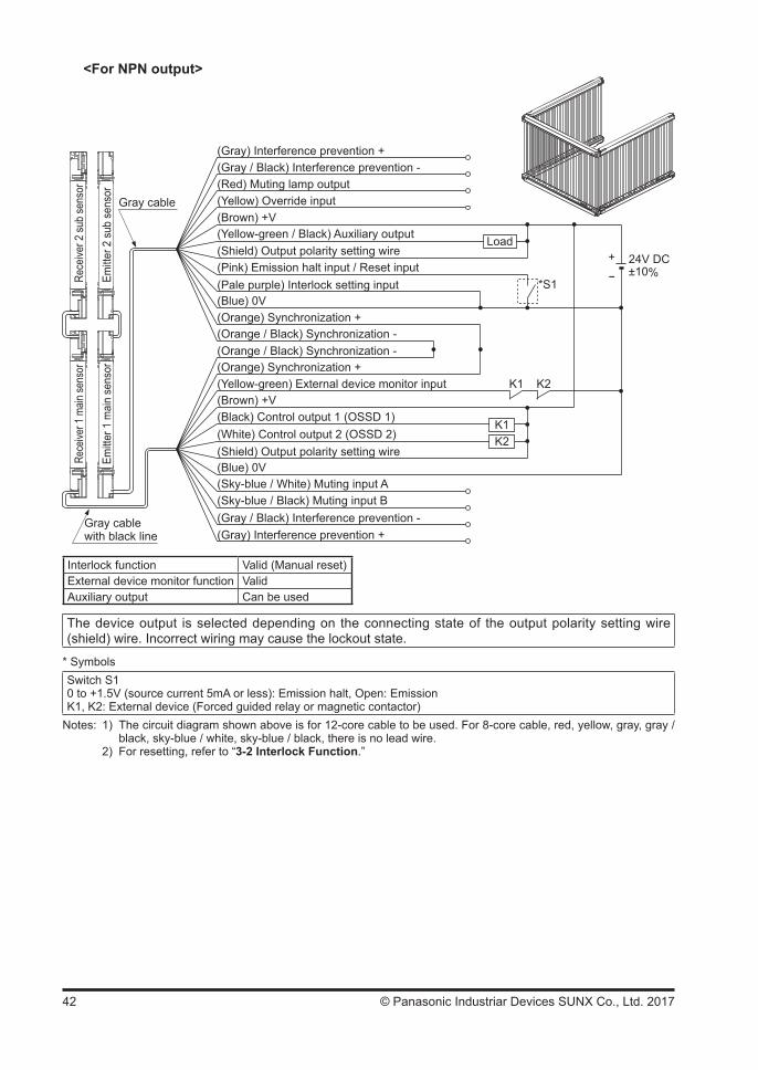
42 © Panasonic Industriar Devices SUNX Co., Ltd. 2017
<For NPN output>
+ 24V DC±10%-
K1K2
Load
*S1
K1 K2
(Shield) Output polarity setting wire
(Blue) 0V
(Brown) +V
(Pale purple) Interlock setting input
(Gray) Interference prevention +(Gray / Black) Interference prevention -(Red) Muting lamp output(Yellow) Override input
(Yellow-green) External device monitor input(Brown) +V
(Shield) Output polarity setting wire
(Sky-blue / White) Muting input A(Sky-blue / Black) Muting input B(Gray / Black) Interference prevention -(Gray) Interference prevention +
(Pink) Emission halt input / Reset input
(Yellow-green / Black) Auxiliary output
(Blue) 0V(Orange) Synchronization +(Orange / Black) Synchronization -
(Orange) Synchronization +(Orange / Black) Synchronization -
Rece
iver 2
sub
sens
or
Emitt
er 2
sub
sen
sor
Rece
iver 1
main
sens
or
Emitt
er 1
mai
n se
nsor
Gray cable
Gray cable with black line
(Black) Control output 1 (OSSD 1)(White) Control output 2 (OSSD 2)
Interlock function Valid (Manual reset)External device monitor function ValidAuxiliary output Can be used
The device output is selected depending on the connecting state of the output polarity setting wire (shield) wire. Incorrect wiring may cause the lockout state.
* SymbolsSwitch S10 to +1.5V (source current 5mA or less): Emission halt, Open: EmissionK1, K2: External device (Forced guided relay or magnetic contactor)
Notes: 1) The circuit diagram shown above is for 12-core cable to be used. For 8-core cable, red, yellow, gray, gray / black, sky-blue / white, sky-blue / black, there is no lead wire. 2) For resetting, refer to “3-2 Interlock Function.”

43© Panasonic Industriar Devices SUNX Co., Ltd. 2017
2-5-7 Parallel Connection (Wiring Example of the Control Category 4)
This is the configuration for connecting multiple sets of emitter and receiver facing each other in parallel. It is used when there are two dangerous parts and each dangerous part can be en-tered from only one direction. By connecting the interference prevention line, up to three sets of the devices can be connected. For the control output (OSSD 1 / 2), only the set of which light is blocked turns OFF.
For parallel connection, connect the one receiver to the other connection using the interference prevention line as shown in the figure on the next page. Wrong con-nection could generate the non-sensing area, resulting in death or serious injury.
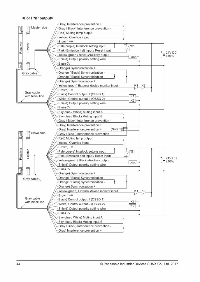
44 © Panasonic Industriar Devices SUNX Co., Ltd. 2017
<For PNP output>
+ 24V DC±10%-
K1K2
Load
*S1
K1 K2
+ 24V DC±10%-
K1K2
Load
*S1
K1 K2
(Note 1)
Rec
eive
r
Em
itter
Gray cable
Rec
eive
r
Em
itter
Master side
Slave side
Gray cable with black line
Gray cable
Gray cable with black line
(Shield) Output polarity setting wire
(Pale purple) Interlock setting input(Brown) +V
(Gray) Interference prevention +(Gray / Black) Interference prevention -(Red) Muting lamp output(Yellow) Override input
(Yellow-green) External device monitor input(Brown) +V
(Blue) 0V(Shield) Output polarity setting wire
(Sky-blue / White) Muting input A(Sky-blue / Black) Muting input B(Gray / Black) Interference prevention -(Gray) Interference prevention +
(Pink) Emission halt input / Reset input(Yellow-green / Black) Auxiliary output
(Blue) 0V(Orange) Synchronization +(Orange / Black) Synchronization -
(Orange) Synchronization +(Orange / Black) Synchronization -
(Gray) Interference prevention +(Gray / Black) Interference prevention -(Red) Muting lamp output(Yellow) Override input(Brown) +V(Pale purple) Interlock setting input(Pink) Emission halt input / Reset input(Yellow-green / Black) Auxiliary output(Shield) Output polarity setting wire(Blue) 0V
(Yellow-green) External device monitor input(Brown) +V
(Shield) Output polarity setting wire(Blue) 0V(Sky-blue / White) Muting input A(Sky-blue / Black) Muting input B
(Gray) Interference prevention +(Gray / Black) Interference prevention -
(Black) Control output 1 (OSSD 1)(White) Control output 2 (OSSD 2)
(Black) Control output 1 (OSSD 1)(White) Control output 2 (OSSD 2)
(Orange) Synchronization +(Orange / Black) Synchronization -
(Orange) Synchronization +(Orange / Black) Synchronization -

45© Panasonic Industriar Devices SUNX Co., Ltd. 2017
Interlock function Valid (Manual reset)External device monitor function ValidAuxiliary output Can be used
The device output is selected depending on the connecting state of the output polarity setting wire (shield).Incorrect wiring may cause the lockout state.
* SymbolsSwitch S1Vs to Vs - 2.5V (sink current 5mA or less): Emission halt (Note 2), Open: EmissionK1, K2: External device (Forced guided relay or magnetic contactor)
Notes: 1) If the interference prevention wire is extended, use a 0.2mm2 or more, shielded twisted pair cable. 2) Vs is the applying supply voltage. 3) For resetting, refer to “3-2 Interlock Function.”
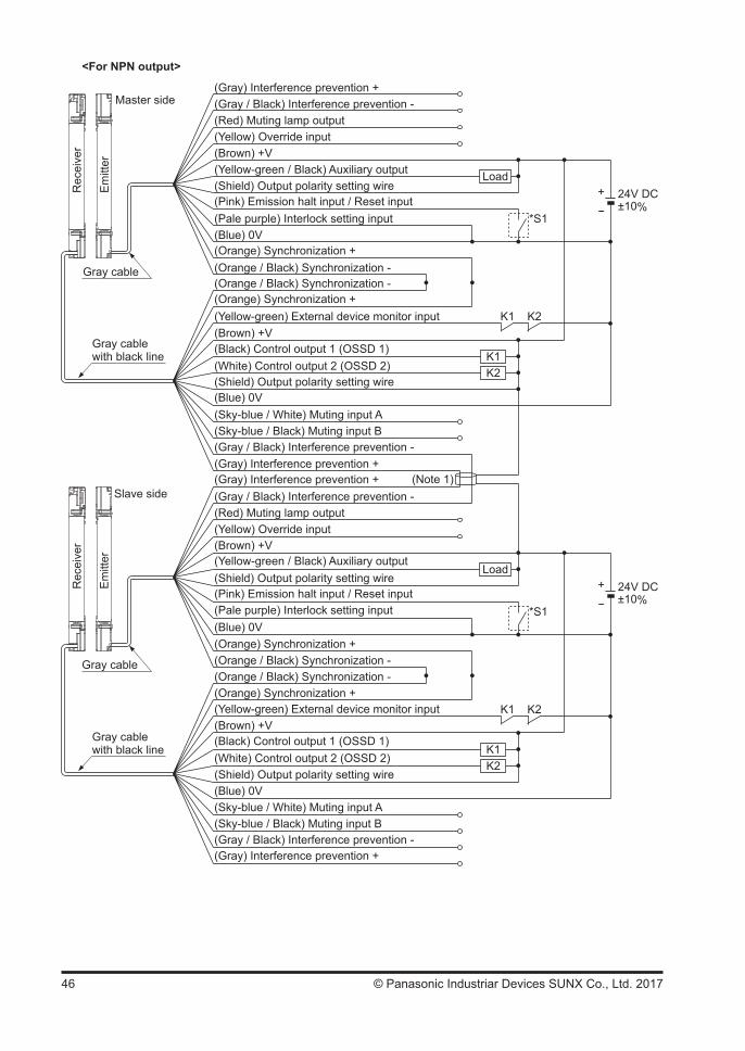
46 © Panasonic Industriar Devices SUNX Co., Ltd. 2017
<For NPN output>
+ 24V DC±10%-
K1K2
Load
*S1
K1 K2
+ 24V DC±10%-
K1K2
Load
*S1
K1 K2
(Note 1)
Master side
Slave side
Gray cable with black line
(Shield) Output polarity setting wire
(Pale purple) Interlock setting input
(Brown) +V
(Gray) Interference prevention +(Gray / Black) Interference prevention -(Red) Muting lamp output(Yellow) Override input
(Yellow-green) External device monitor input(Brown) +V
(Blue) 0V(Shield) Output polarity setting wire
(Sky-blue / White) Muting input A(Sky-blue / Black) Muting input B(Gray / Black) Interference prevention -(Gray) Interference prevention +
(Pink) Emission halt input / Reset input
(Yellow-green / Black) Auxiliary output
(Blue) 0V
(Gray) Interference prevention +(Gray / Black) Interference prevention -(Red) Muting lamp output(Yellow) Override input(Brown) +V
(Pale purple) Interlock setting input(Pink) Emission halt input / Reset input
(Yellow-green / Black) Auxiliary output(Shield) Output polarity setting wire
(Blue) 0V
(Yellow-green) External device monitor input(Brown) +V
(Shield) Output polarity setting wire(Blue) 0V(Sky-blue / White) Muting input A(Sky-blue / Black) Muting input B
(Gray) Interference prevention +(Gray / Black) Interference prevention -
Rec
eive
r
Em
itter
Rec
eive
r
Em
itter
Gray cable
Gray cable
Gray cable with black line
(Black) Control output 1 (OSSD 1)(White) Control output 2 (OSSD 2)
(Black) Control output 1 (OSSD 1)(White) Control output 2 (OSSD 2)
(Orange) Synchronization +(Orange / Black) Synchronization -
(Orange) Synchronization +(Orange / Black) Synchronization -
(Orange) Synchronization +(Orange / Black) Synchronization -
(Orange) Synchronization +(Orange / Black) Synchronization -
47© Panasonic Industriar Devices SUNX Co., Ltd. 2017
Interlock function Valid (Manual reset)External device monitor function ValidAuxiliary output Can be used
The device output is selected depending on the connecting state of the output polarity setting wire (shield).Incorrect wiring may cause the lockout state.
* SymbolsSwitch S10 to +1.5V (source current 5mA or less): Emission halt, Open: EmissionK1, K2: External device (Forced guided relay or magnetic contactor)
Notes: 1) If the interference prevention wire is extended, use a 0.2mm2 or more, shielded twisted pair cable. 2) For resetting, refer to “3-2 Interlock Function.”
2-5-8 Series and Parallel Mixed Connection(Wiring Example of the Control Category 4)
This is the configuration for connecting multiple sets of emitter and receiver facing each other in mixed series and parallel combination. It is used when there are two or more dangerous parts that can be entered from two or more directions. Up to three sets of the devices in total of the series connection and parallel connection can be connected in combination. However, the total number of beam channels available is 192. In case of series connection, if any of the sets is in light blocked status, the control output (OSSD 1 / 2) turns OFF. In case of parallel connection, for the control output (OSSD 1 / 2), only the set of which light is blocked turns OFF.
For series connection, connect the emitter and emitter, receiver and receiver respectively using the exclusive cable (SFB-CSL) for series connection as shown in the figure on the next page. Wrong connection could generate the non-sensing area, resulting in death or serious injury.
For parallel connection, connect the one receiver to the other connection using the interference prevention line as shown in the figure on the next page. Wrong connection could generate the non-sensing area, resulting in death or serious injury

48 © Panasonic Industriar Devices SUNX Co., Ltd. 2017
<For PNP output>
+ 24V DC±10%-
K1K2
Load
*S1
K1 K2
+ 24V DC±10%-
K1K2
Load
*S1
K1 K2
Master side
(Note 1)
Gray cable
Rec
eive
r
Em
itter
Slave side
Gray cable with black line
Gray cable
Gray cable with black line
(Shield) Output polarity setting wire
(Pale purple) Interlock setting input(Brown) +V
(Gray) Interference prevention +(Gray / Black) Interference prevention -(Red) Muting lamp output(Yellow) Override input
(Yellow-green) External device monitor input(Brown) +V
(Blue) 0V(Shield) Output polarity setting wire
(Sky-blue / White) Muting input A(Sky-blue / Black) Muting input B(Gray / Black) Interference prevention -(Gray) Interference prevention +
(Pink) Emission halt input / Reset input(Yellow-green / Black) Auxiliary output
(Blue) 0V(Orange) Synchronization +(Orange / Black) Synchronization -
(Orange) Synchronization +(Orange / Black) Synchronization -
(Gray) Interference prevention +(Gray / Black) Interference prevention -(Red) Muting lamp output(Yellow) Override input(Brown) +V(Pale purple) Interlock setting input(Pink) Emission halt input / Reset input(Yellow-green / Black) Auxiliary output(Shield) Output polarity setting wire(Blue) 0V
(Yellow-green) External device monitor input(Brown) +V
(Shield) Output polarity setting wire(Blue) 0V(Sky-blue / White) Muting input A(Sky-blue / Black) Muting input B
(Gray) Interference prevention +(Gray / Black) Interference prevention -
Rece
iver 1
main
sens
or
Emitt
er 1
mai
n se
nsor
Rece
iver 2
sub
sen
sor
Emitt
er 2
sub
sen
sor
(Black) Control output 1 (OSSD 1)(White) Control output 2 (OSSD 2)
(Black) Control output 1 (OSSD 1)(White) Control output 2 (OSSD 2)
(Orange) Synchronization +(Orange / Black) Synchronization -
(Orange) Synchronization +(Orange / Black) Synchronization -
49© Panasonic Industriar Devices SUNX Co., Ltd. 2017
Interlock function Valid (Manual reset)External device monitor function ValidAuxiliary output Can be used
The device output is selected depending on the connecting state of the output polarity setting wire (shield).Incorrect wiring may cause the lockout state.
* SymbolsSwitch S1Vs to Vs - 2.5V (sink current 5mA or less): Emission halt (Note 2), Open: EmissionK1, K2: External device (Forced guided relay or magnetic contactor)
Notes: 1) If the interference prevention wire is extended, use a 0.2mm2 or more, shielded twisted pair cable. 2) Vs is the applying supply voltage. 3) For resetting, refer to “3-2 Interlock Function.”
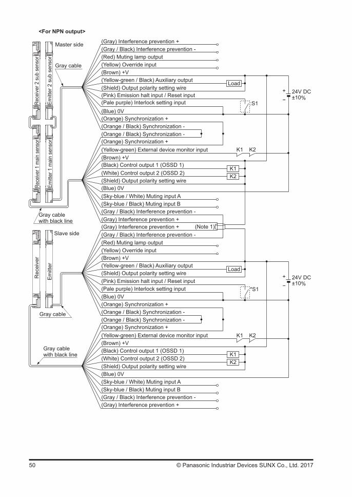
50 © Panasonic Industriar Devices SUNX Co., Ltd. 2017
<For NPN output>
+ 24V DC±10%-
K1K2
Load
:S1
K1 K2
+ 24V DC±10%-
K1K2
Load
*S1
K1 K2
(Note 1)
Rec
eive
r
Em
itter
Gray cable
Rece
iver 1
main
sens
or
Emitt
er 1
mai
n se
nsor
Rece
iver 2
sub
sen
sor
Emitt
er 2
sub
sen
sor
Master side
Gray cable
Gray cable with black line
Slave side
Gray cable with black line
(Brown) +V
(Gray) Interference prevention +(Gray / Black) Interference prevention -(Red) Muting lamp output(Yellow) Override input
(Yellow-green / Black) Auxiliary output(Shield) Output polarity setting wire
(Pale purple) Interlock setting input(Pink) Emission halt input / Reset input
(Yellow-green) External device monitor input(Brown) +V
(Blue) 0V(Shield) Output polarity setting wire
(Sky-blue / White) Muting input A(Sky-blue / Black) Muting input B(Gray / Black) Interference prevention -(Gray) Interference prevention +
(Blue) 0V(Orange) Synchronization +(Orange / Black) Synchronization -
(Orange) Synchronization +(Orange / Black) Synchronization -
(Gray) Interference prevention +(Gray / Black) Interference prevention -(Red) Muting lamp output(Yellow) Override input(Brown) +V
(Blue) 0V
(Yellow-green) External device monitor input(Brown) +V
(Shield) Output polarity setting wire(Blue) 0V(Sky-blue / White) Muting input A(Sky-blue / Black) Muting input B
(Gray) Interference prevention +(Gray / Black) Interference prevention -
(Pale purple) Interlock setting input(Pink) Emission halt input / Reset input
(Yellow-green / Black) Auxiliary output(Shield) Output polarity setting wire
(Black) Control output 1 (OSSD 1)(White) Control output 2 (OSSD 2)
(Black) Control output 1 (OSSD 1)(White) Control output 2 (OSSD 2)
(Orange) Synchronization +(Orange / Black) Synchronization -
(Orange) Synchronization +(Orange / Black) Synchronization -

51© Panasonic Industriar Devices SUNX Co., Ltd. 2017
Interlock function Valid (Manual reset)External device monitor function ValidAuxiliary output Can be used
The device output is selected depending on the connecting state of the output polarity setting wire (shield).Incorrect wiring may cause the lockout state.
* SymbolsSwitch S10 to +1.5V (source current 5mA or less): Emission halt, Open: EmissionK1, K2: External device (Forced guided relay or magnetic contactor)
Notes: 1) If the interference prevention wire is extended, use a 0.2mm2 or more, shielded twisted pair cable. 2) For resetting, refer to “3-2 Interlock Function.”

52 © Panasonic Industriar Devices SUNX Co., Ltd. 2017
2-5-9 Wiring for Auto-reset (Interlock is Invalid)(Wiring Example of the Control Category 4)
<For PNP output>
+ 24V DC±10%-
K1K2
Load
*S1
K1 K2
Rec
eive
r
Em
itter
Gray cable
Gray cable with black line
(Gray) Interference prevention +(Gray / Black) Interference prevention -(Red) Muting lamp output(Yellow) Override input
(Brown) +V
(Yellow-green) External device monitor input(Brown) +V
(Shield) Output polarity setting wire(Blue) 0V(Sky-blue / White) Muting input A(Sky-blue / Black) Muting input B
(Gray) Interference prevention +(Gray / Black) Interference prevention -
(Pale purple) Interlock setting input
(Pink) Emission halt input / Reset input(Yellow-green / Black) Auxiliary output(Shield) Output polarity setting wire
(Orange) Synchronization +(Orange / Black) Synchronization -
(Orange) Synchronization +(Orange / Black) Synchronization -
(Blue) 0V
(Black) Control output 1 (OSSD 1)(White) Control output 2 (OSSD 2)
Interlock function Invalid (Auto-reset)External device monitor function ValidAuxiliary output Can be used
The device output is selected depending on the connecting state of the output polarity setting wire (shield). Incorrect wiring may cause the lockout state.
* SymbolsSwitch S1Vs to Vs - 2.5V (sink current 5mA or less): Emission (Note 1), Open: Emission haltK1, K2: External device (Forced guided relay or magnetic contactor)
Notes: 1) Vs is the applying supply voltage. 2) The circuit diagram shown above is for 12-core cable to be used. For 8-core cable, red, yellow, gray, gray / black, sky-blue / white, sky-blue / black, there is no lead wire. 3) For resetting, refer to “3-2 Interlock Function.”

53© Panasonic Industriar Devices SUNX Co., Ltd. 2017
<For NPN output>
+ 24V DC±10%-
K1K2
Load
*S1
K1 K2
Rec
eive
r
Em
itter
Gray cable
Gray cable with black line
(Gray) Interference prevention +(Gray / Black) Interference prevention -(Red) Muting lamp output(Yellow) Override input
(Brown) +V
(Yellow-green) External device monitor input(Brown) +V
(Shield) Output polarity setting wire(Blue) 0V(Sky-blue / White) Muting input A(Sky-blue / Black) Muting input B
(Gray) Interference prevention +(Gray / Black) Interference prevention -
(Pale purple) Interlock setting input
(Pink) Emission halt input / Reset input
(Yellow-green / Black) Auxiliary output(Shield) Output polarity setting wire
(Orange) Synchronization +(Orange / Black) Synchronization -
(Orange) Synchronization +(Orange / Black) Synchronization -
(Blue) 0V
(Black) Control output 1 (OSSD 1)(White) Control output 2 (OSSD 2)
Interlock function Invalid (Auto-reset)External device monitor function ValidAuxiliary output Can be used
The device output is selected depending on the connecting state of the output polarity setting wire (shield). Incorrect wiring may cause the lockout state.
* SymbolsSwitch S10 to +1.5V (source current 5mA or less): Emission, Open: Emission haltK1, K2: External device (Forced guided relay or magnetic contactor)
Notes: 1) The circuit diagram shown above is for 12-core cable to be used. For 8-core cable, red, yellow, gray, gray / black, sky-blue / white, sky-blue / black, there is no lead wire. 2) For resetting, refer to “3-2 Interlock Function.”
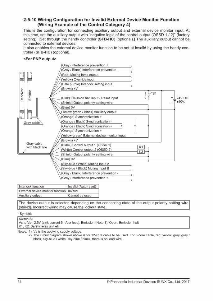
54 © Panasonic Industriar Devices SUNX Co., Ltd. 2017
2-5-10 Wiring Configuration for Invalid External Device Monitor Function(Wiring Example of the Control Category 4)
This is the configuration for connecting auxiliary output and external device monitor input. At this time, set the auxiliary output with “negative logic of the control output (OSSD 1 / 2)” (factory setting). [Set through the handy controller (SFB-HC) (optional).] The auxiliary output cannot be connected to external devices.It also enables the external device monitor function to be set at invalid by using the handy con-troller (SFB-HC) (optional).
<For PNP output>
+ 24V DC±10%-
K1K2
*S1
Rec
eive
r
Em
itter
(Gray) Interference prevention +(Gray / Black) Interference prevention -(Red) Muting lamp output(Yellow) Override input
(Brown) +V
(Yellow-green) External device monitor input(Brown) +V
(Shield) Output polarity setting wire(Blue) 0V(Sky-blue / White) Muting input A(Sky-blue / Black) Muting input B
(Gray) Interference prevention +(Gray / Black) Interference prevention -
(Pale purple) Interlock setting input
(Pink) Emission halt input / Reset input
(Yellow-green / Black) Auxiliary output
(Shield) Output polarity setting wire
(Orange) Synchronization +(Orange / Black) Synchronization -
(Orange) Synchronization +(Orange / Black) Synchronization -
(Blue) 0V
Gray cable
Gray cable with black line
(Black) Control output 1 (OSSD 1)(White) Control output 2 (OSSD 2)
Interlock function Invalid (Auto-reset)External device monitor function InvalidAuxiliary output Cannot be used
The device output is selected depending on the connecting state of the output polarity setting wire (shield). Incorrect wiring may cause the lockout state.
* SymbolsSwitch S1Vs to Vs - 2.5V (sink current 5mA or less): Emission (Note 1), Open: Emission haltK1, K2: Safety relay unit etc.
Notes: 1) Vs is the applying supply voltage. 2) The circuit diagram shown above is for 12-core cable to be used. For 8-core cable, red, yellow, gray, gray / black, sky-blue / white, sky-blue / black, there is no lead wire.
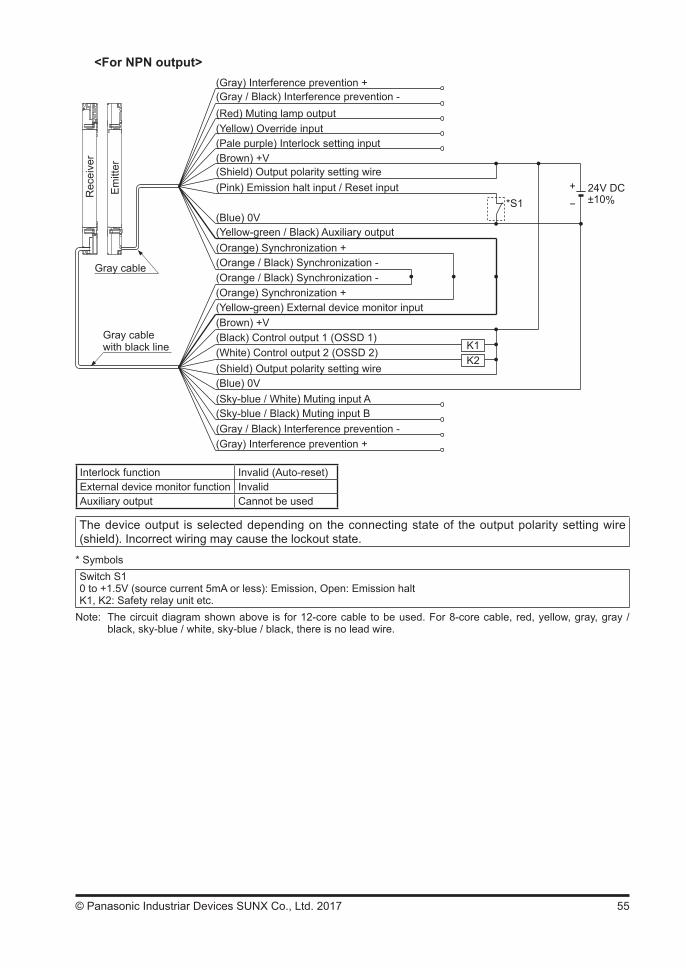
55© Panasonic Industriar Devices SUNX Co., Ltd. 2017
<For NPN output>
+ 24V DC±10%-
K1K2
*S1
Rec
eive
r
Em
itter
Gray cable
Gray cable with black line
(Gray) Interference prevention +(Gray / Black) Interference prevention -(Red) Muting lamp output(Yellow) Override input
(Brown) +V
(Yellow-green) External device monitor input(Brown) +V
(Shield) Output polarity setting wire(Blue) 0V(Sky-blue / White) Muting input A(Sky-blue / Black) Muting input B
(Gray) Interference prevention +(Gray / Black) Interference prevention -
(Pale purple) Interlock setting input
(Pink) Emission halt input / Reset input
(Yellow-green / Black) Auxiliary output
(Shield) Output polarity setting wire
(Orange) Synchronization +(Orange / Black) Synchronization -
(Orange) Synchronization +(Orange / Black) Synchronization -
(Blue) 0V
(Black) Control output 1 (OSSD 1)(White) Control output 2 (OSSD 2)
Interlock function Invalid (Auto-reset)External device monitor function InvalidAuxiliary output Cannot be used
The device output is selected depending on the connecting state of the output polarity setting wire (shield). Incorrect wiring may cause the lockout state.
* SymbolsSwitch S10 to +1.5V (source current 5mA or less): Emission, Open: Emission haltK1, K2: Safety relay unit etc.
Note: The circuit diagram shown above is for 12-core cable to be used. For 8-core cable, red, yellow, gray, gray / black, sky-blue / white, sky-blue / black, there is no lead wire.
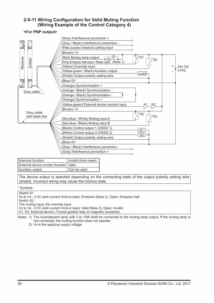
56 © Panasonic Industriar Devices SUNX Co., Ltd. 2017
2-5-11 Wiring Configuration for Valid Muting Function (Wiring Example of the Control Category 4)
<For PNP output>
+ 24V DC±10%-
K1K2
*S1(Note 1) *S2
Load
*S2*S2
K1 K2
Rec
eive
r
Em
itter
(Gray) Interference prevention +(Gray / Black) Interference prevention -
(Red) Muting lamp output
(Yellow) Override input
(Brown) +V
(Yellow-green) External device monitor input(Brown) +V
(Shield) Output polarity setting wire(Blue) 0V
(Sky-blue / White) Muting input A(Sky-blue / Black) Muting input B
(Gray) Interference prevention +(Gray / Black) Interference prevention -
(Pale purple) Interlock setting input
(Pink) Emission halt input / Reset input
(Yellow-green / Black) Auxiliary output(Shield) Output polarity setting wire
(Orange) Synchronization +(Orange / Black) Synchronization -
(Orange) Synchronization +(Orange / Black) Synchronization -
(Blue) 0V
Gray cable
Gray cable with black line
(Black) Control output 1 (OSSD 1)(White) Control output 2 (OSSD 2)
Interlock function Invalid (Auto-reset)External device monitor function ValidAuxiliary output Can be used
The device output is selected depending on the connecting state of the output polarity setting wire (shield). Incorrect wiring may cause the lockout state.
* SymbolsSwitch S1Vs to Vs - 2.5V (sink current 5mA or less): Emission (Note 2), Open: Emission halt Switch S2The muting input, the override inputVs to Vs - 2.5V (sink current 5mA or less): Valid (Note 2), Open: InvalidK1, K2: External device ( Forced guided relay or magnetic contactor)
Notes: 1) The incandescent lamp with 3 to 10W shall be connected to the muting lamp output. If the muting lamp is not connected, the muting function does not operate. 2) Vs is the applying supply voltage.
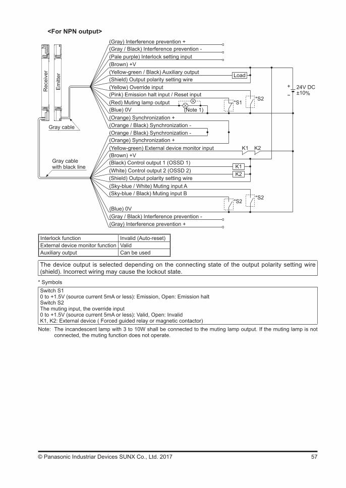
57© Panasonic Industriar Devices SUNX Co., Ltd. 2017
<For NPN output>
+ 24V DC±10%-
K1K2
*S1(Note 1)
*S2
Load
*S2*S2
K1 K2
Rec
eive
r
Em
itter
Gray cable
Gray cable with black line
(Gray) Interference prevention +(Gray / Black) Interference prevention -
(Red) Muting lamp output
(Yellow) Override input
(Brown) +V
(Yellow-green) External device monitor input(Brown) +V
(Shield) Output polarity setting wire
(Blue) 0V
(Sky-blue / White) Muting input A(Sky-blue / Black) Muting input B
(Gray) Interference prevention +(Gray / Black) Interference prevention -
(Pale purple) Interlock setting input
(Pink) Emission halt input / Reset input
(Yellow-green / Black) Auxiliary output(Shield) Output polarity setting wire
(Orange) Synchronization +(Orange / Black) Synchronization -
(Orange) Synchronization +(Orange / Black) Synchronization -
(Blue) 0V
(Black) Control output 1 (OSSD 1)(White) Control output 2 (OSSD 2)
Interlock function Invalid (Auto-reset)External device monitor function ValidAuxiliary output Can be used
The device output is selected depending on the connecting state of the output polarity setting wire (shield). Incorrect wiring may cause the lockout state.
* SymbolsSwitch S10 to +1.5V (source current 5mA or less): Emission, Open: Emission haltSwitch S2The muting input, the override input0 to +1.5V (source current 5mA or less): Valid, Open: InvalidK1, K2: External device ( Forced guided relay or magnetic contactor)
Note: The incandescent lamp with 3 to 10W shall be connected to the muting lamp output. If the muting lamp is not connected, the muting function does not operate.
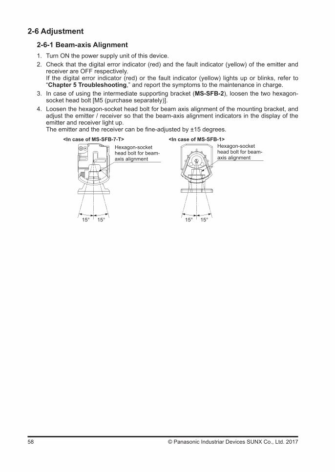
58 © Panasonic Industriar Devices SUNX Co., Ltd. 2017
2-6 Adjustment2-6-1 Beam-axis Alignment1. Turn ON the power supply unit of this device.2. Check that the digital error indicator (red) and the fault indicator (yellow) of the emitter and
receiver are OFF respectively. If the digital error indicator (red) or the fault indicator (yellow) lights up or blinks, refer to
“Chapter 5 Troubleshooting,” and report the symptoms to the maintenance in charge.3. In case of using the intermediate supporting bracket (MS-SFB-2), loosen the two hexagon-
socket head bolt [M5 (purchase separately)].4. Loosen the hexagon-socket head bolt for beam axis alignment of the mounting bracket, and
adjust the emitter / receiver so that the beam-axis alignment indicators in the display of the emitter and receiver light up.
The emitter and the receiver can be fine-adjusted by ±15 degrees.
Hexagon-socket head bolt for beam-axis alignment
<In case of MS-SFB-7-T> <In case of MS-SFB-1>
15° 15° 15° 15°
Hexagon-socket head bolt for beam-axis alignment
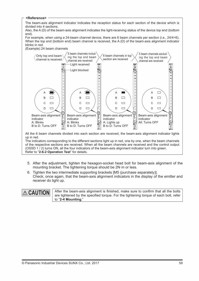
59© Panasonic Industriar Devices SUNX Co., Ltd. 2017
The beam-axis alignment indicator indicates the reception status for each section of the device which is divided into 4 sections.Also, the A (D) of the beam-axis alignment indicates the light-receiving status of the device top end (bottom end).For example, when using a 24-beam channel device, there are 6 beam channels per section (i.e., 24/4=6). When the top end (bottom end) beam channel is received, the A (D) of the beam-axis alignment indicator blinks in red.(Example) 24 beam channels
A
B
C
D
A
B
C
D
A
B
C
D
A
B
C
D
Only top end beam channel is received
5 beam channels includ-ing the top end beam channel are received
6 beam channels in top section are received
5 beam channels exclud-ing the top end beam channel are received
Light received
Light blocked
Beam-axis alignment indicatorA: BlinksB to D: Turns OFF
Beam-axis alignment indicatorA: BlinksB to D: Turns OFF
Beam-axis alignment indicatorA: Lights upB to D: Turns OFF
Beam-axis alignment indicatorAll: Turns OFF
All the 6 beam channels divided into each section are received, the beam-axis alignment indicator lights up in red.The indicators corresponding to the different sections light up in red, one by one, when the beam channels of the respective sections are received. When all the beam channels are received and the control output (OSSD 1 / 2) turns ON, all the four indicators of the beam-axis alignment indicator turn into green.Refer to “2-6-2 Operation Test” for details.
5. After the adjustment, tighten the hexagon-socket head bolt for beam-axis alignment of the mounting bracket. The tightening torque should be 2N·m or less.
6. Tighten the two intermediate supporting brackets [M5 (purchase separately)]. Check, once again, that the beam-axis alignment indicators in the display of the emitter and
receiver do light up.
After the beam-axis alignment is finished, make sure to confirm that all the bolts are tightened by the specified torque. For the tightening torque of each bolt, refer to “2-4 Mounting.”
<Reference>
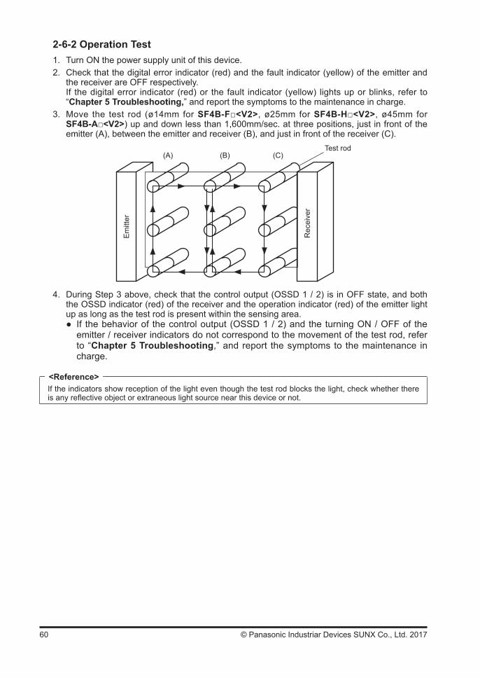
60 © Panasonic Industriar Devices SUNX Co., Ltd. 2017
2-6-2 Operation Test1. Turn ON the power supply unit of this device.2. Check that the digital error indicator (red) and the fault indicator (yellow) of the emitter and
the receiver are OFF respectively. If the digital error indicator (red) or the fault indicator (yellow) lights up or blinks, refer to
“Chapter 5 Troubleshooting,” and report the symptoms to the maintenance in charge.3. Move the test rod (ø14mm for SF4B-F<V2>, ø25mm for SF4B-H<V2>, ø45mm for
SF4B-A<V2>) up and down less than 1,600mm/sec. at three positions, just in front of the emitter (A), between the emitter and receiver (B), and just in front of the receiver (C).
Test rod(A) (B) (C)
Em
itter
Rec
eive
r4. During Step 3 above, check that the control output (OSSD 1 / 2) is in OFF state, and both
the OSSD indicator (red) of the receiver and the operation indicator (red) of the emitter light up as long as the test rod is present within the sensing area.
If the behavior of the control output (OSSD 1 / 2) and the turning ON / OFF of the emitter / receiver indicators do not correspond to the movement of the test rod, refer to “Chapter 5 Troubleshooting,” and report the symptoms to the maintenance in charge.
If the indicators show reception of the light even though the test rod blocks the light, check whether there is any reflective object or extraneous light source near this device or not.
<Reference>
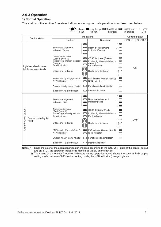
61© Panasonic Industriar Devices SUNX Co., Ltd. 2017
2-6-3 Operation1) Normal OperationThe status of the emitter / receiver indicators during normal operation is as described below.
: Blinks in red
: Lights up in red
: Lights up in green
: Lights up in orange
: TurnsOFF
Device statusIndicators Control output
Emitter Receiver OSSD 1 OSSD 2
Light received status(all beams received)
Beam-axis alignment indicator (Green)
PNP indicator (Orange) (Note 2)
Emission halt indicator
Operation indicator (Green) (Note 1)Incident light intensity indicator
Fault indicator(Green)
Digital error indicator
NPN indicator
Emission intensity control indicator
Interlock indicator
Function setting indicator
Beam-axis alignment indicator (Green)
PNP indicator (Orange) (Note 2)
OSSD indicator (Green)Incident light intensity indicator
Fault indicator
Digital error indicator
NPN indicator
(Green)
ON
Ligh
t blo
cked
sta
tus
One or more lights block
Beam-axis alignment indicator (Red)
PNP indicator (Orange) (Note 2)
Emission halt indicator
Operation indicator(Red) (Note 1)Incident light intensity indicatorFault indicator
Digital error indicator
NPN indicator
Emission intensity control indicator
Interlock indicator
OSSD Indicator (Red)Incident light intensity indicatorFault indicator
Digital error indicator
PNP indicator (Orange) (Note 2)NPN indicator
Function setting indicator
Beam-axis alignment indicator (Red)
OFF
Notes: 1) Since the color of the operation indicator changes according to the ON / OFF state of the control output (OSSD 1 / 2), the operation indicator is marked as OSSD on the device.
2) The status of the emitter / receiver indicators during operation above shows the case in PNP output setting mode. In case of NPN output setting mode, the NPN indicator (orange) lights up.
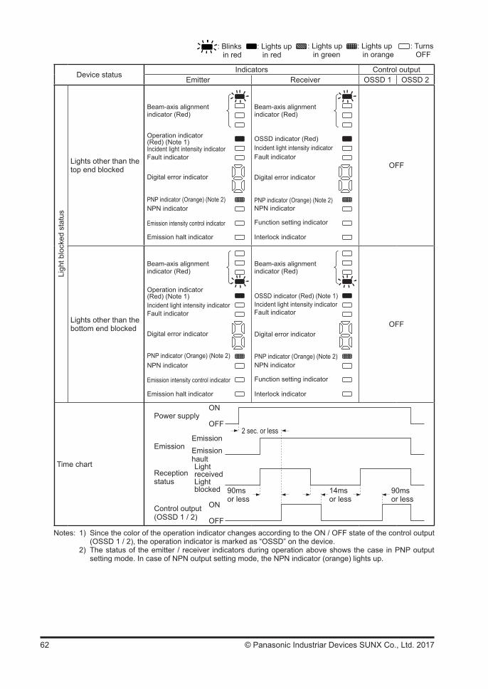
62 © Panasonic Industriar Devices SUNX Co., Ltd. 2017
: Blinks in red
: Lights up in red
: Lights up in green
: Lights up in orange
: TurnsOFF
Device statusIndicators Control output
Emitter Receiver OSSD 1 OSSD 2
Ligh
t blo
cked
sta
tus
Lights other than the top end blocked
Beam-axis alignment indicator (Red)
PNP indicator (Orange) (Note 2)
Emission halt indicator
Operation indicator (Red) (Note 1)Incident light intensity indicatorFault indicator
Digital error indicator
NPN indicator
Emission intensity control indicator
Incident light intensity indicator
Beam-axis alignment indicator (Red)
OSSD indicator (Red)
Fault indicator
Digital error indicator
PNP indicator (Orange) (Note 2)NPN indicator
Interlock indicator
Function setting indicator
OFF
Lights other than the bottom end blocked
Beam-axis alignment indicator (Red)
PNP indicator (Orange) (Note 2)
Emission halt indicator
Operation indicator (Red) (Note 1)Incident light intensity indicatorFault indicator
Digital error indicator
NPN indicator
Emission intensity control indicator
Incident light intensity indicator
Beam-axis alignment indicator (Red)
OSSD indicator (Red) (Note 1)
Fault indicator
Digital error indicator
PNP indicator (Orange) (Note 2)NPN indicator
Interlock indicator
Function setting indicator
OFF
Time chart
ON
OFFPower supply
EmissionEmissionhault
Emission
2 sec. or less
ON
OFFControl output(OSSD 1 / 2)
LightreceivedLight blocked
Receptionstatus
90msor less
90msor less
14msor less
Notes: 1) Since the color of the operation indicator changes according to the ON / OFF state of the control output (OSSD 1 / 2), the operation indicator is marked as “OSSD” on the device.
2) The status of the emitter / receiver indicators during operation above shows the case in PNP output setting mode. In case of NPN output setting mode, the NPN indicator (orange) lights up.

63© Panasonic Industriar Devices SUNX Co., Ltd. 2017
<For series connection>In case of series connection, if any of the sets is in light blocked status, the control output (OSSD 1 / 2) turns OFF.
The emitter / receiver indicators indicates the output status.
The following figure shows the status of the indicators with Sub sensor 2 in light blocked status.: Lights up in red : Lights up in orange : Turns OFF
Sub sensor 3
Sub sensor 2: Light blocked status
Main sensor 1: Light received status
<Received>
<Received>
<Emitter> <Received>
Em
itter
Rec
eive
r
Incident light intensity indicator
Beam-axis alignment indicator (Red)
OSSD indicator (Red)
Fault indicator
Digital error indicator
PNP indicator (Orange) (Note 2)
NPN indicator
Interlock indicator
Function setting indicator
Beam-axis alignmentindicator (Red)
PNP indicator (Orange) (Note 2)
Emission halt indicator
Operation indicator (Red) (Note 1)Incident light intensity indicatorFault indicator
Digital error indicator
NPN indicator
Emission intensity control indicator
Incident light intensity indicator
Beam-axis alignment indicator (Red)
OSSD indicator (Red)
Fault indicator
Digital error indicator
PNP indicator (Orange) (Note 2)NPN indicator
Interlock indicator
Function setting indicator
<Emitter>
Sub sensor 3: Light received status<Emitter>
Sub sensor 2
Main sensor 1
Em
itter
Rec
eive
r
Em
itter
Rec
eive
r
Synchronization wire
PNP indicator (Orange) (Note 2)
Emission halt indicator
Incident light intensity indicator Fault indicator
Digital error indicator
NPN indicator
Emission intensity control indicator
Beam-axis alignmentindicator (Red)
Operation indicator (Red) (Note 1)
Notes: 1) Since the color of the operation indicator changes according to the ON / OFF state of the control output (OSSD 1 / 2), the operation indicator is marked as “OSSD” on the device.
2) The status of the emitter / receiver indicators during operation above shows the case in PNP output setting mode. In case of NPN output setting mode, the NPN indicator (orange) lights up.
<Reference>
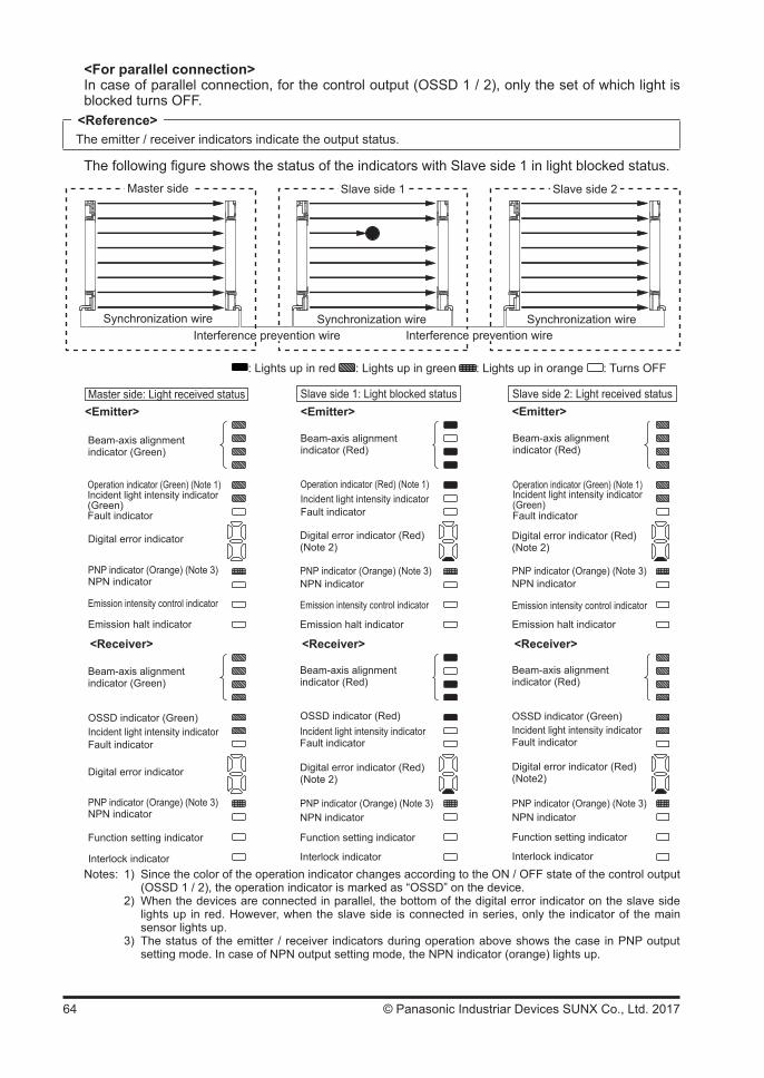
64 © Panasonic Industriar Devices SUNX Co., Ltd. 2017
<For parallel connection>In case of parallel connection, for the control output (OSSD 1 / 2), only the set of which light is blocked turns OFF.
The emitter / receiver indicators indicate the output status.
The following figure shows the status of the indicators with Slave side 1 in light blocked status.Master side Slave side 2Slave side 1
Master side: Light received status Slave side 1: Light blocked status Slave side 2: Light received status
<Receiver>
Interference prevention wireSynchronization wire Synchronization wire Synchronization wire
Interference prevention wire
: Lights up in red : Lights up in green : Lights up in orange : Turns OFF
Beam-axis alignment indicator (Green)
PNP indicator (Orange) (Note 3)
Emission halt indicator
Operation indicator (Green) (Note 1)Incident light intensity indicator
Fault indicator(Green)
Digital error indicator
NPN indicator
Emission intensity control indicator
Interlock indicator
Function setting indicator
Beam-axis alignment indicator (Green)
PNP indicator (Orange) (Note 3)
OSSD indicator (Green)Incident light intensity indicatorFault indicator
Digital error indicator
NPN indicator
<Emitter>
Beam-axis alignment indicator (Red)
PNP indicator (Orange) (Note 3)
Emission halt indicator
Operation indicator (Red) (Note 1)Incident light intensity indicatorFault indicator
Digital error indicator (Red)(Note 2)
NPN indicator
Emission intensity control indicator
Beam-axis alignment indicator (Red)
PNP indicator (Orange) (Note 3)
Interlock indicator
OSSD indicator (Red)Incident light intensity indicatorFault indicator
Digital error indicator (Red)(Note 2)
NPN indicator
Function setting indicator
Beam-axis alignment indicator (Red)
PNP indicator (Orange) (Note 3)
Emission halt indicator
Operation indicator (Green) (Note 1)Incident light intensity indicator(Green)Fault indicator
Digital error indicator (Red)(Note 2)
NPN indicator
Emission intensity control indicator
Beam-axis alignment indicator (Red)
PNP indicator (Orange) (Note 3)
OSSD indicator (Green)Incident light intensity indicatorFault indicator
Digital error indicator (Red)(Note2)
NPN indicator
<Emitter> <Emitter>
<Receiver> <Receiver>
Interlock indicator
Function setting indicator
Notes: 1) Since the color of the operation indicator changes according to the ON / OFF state of the control output (OSSD 1 / 2), the operation indicator is marked as “OSSD” on the device.
2) When the devices are connected in parallel, the bottom of the digital error indicator on the slave side lights up in red. However, when the slave side is connected in series, only the indicator of the main sensor lights up.
3) The status of the emitter / receiver indicators during operation above shows the case in PNP output setting mode. In case of NPN output setting mode, the NPN indicator (orange) lights up.
<Reference>
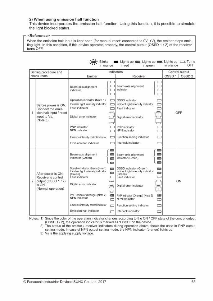
65© Panasonic Industriar Devices SUNX Co., Ltd. 2017
2) When using emission halt functionThis device incorporates the emission halt function. Using this function, it is possible to simulate the light blocked status.
When the emission halt input is kept open (for manual reset: connected to 0V, +V), the emitter stops emit-ting light. In this condition, if this device operates properly, the control output (OSSD 1 / 2) of the receiver turns OFF.
: Blinks in orange
: Lights up in red
: Lights up in green
: Lights up in orange
: TurnsOFF
Setting procedure and check items
Indicators Control outputEmitter Receiver OSSD 1 OSSD 2
1
Before power is ON, Connect the emis-sion halt input / reset input to Vs. (Note 3)
Beam-axis alignment indicator
PNP indicator
Emission halt indicator
Operation indicator (Note 1)Incident light intensity indicatorFault indicator
Digital error indicator
NPN indicator
Emission intensity control indicator
Interlock indicator
Function setting indicator
Beam-axis alignment indicator
PNP indicator
OSSD indicatorIncident light intensity indicatorFault indicator
Digital error indicator
NPN indicator
OFF
2
After power is ON, Receiver’s control output (OSSD 1 / 2) is ON.(Normal operation)
Beam-axis alignment indicator (Green)
PNP indicator (Orange) (Note 2)
Emission halt indicator
Operation indicator (Green) (Note 1)Incident light intensity indicator
Fault indicator(Green)
Digital error indicator
NPN indicator
Emission intensity control indicator
Interlock indicator
Function setting indicator
Beam-axis alignment indicator (Green)
PNP indicator (Orange) (Note 2)
OSSD indicator (Green)Incident light intensity indicator
Fault indicator
Digital error indicator
NPN indicator
(Green)
ON
Notes: 1) Since the color of the operation indicator changes according to the ON / OFF state of the control output (OSSD 1 / 2), the operation indicator is marked as “OSSD” on the device.
2) The status of the emitter / receiver indicators during operation above shows the case in PNP output setting mode. In case of NPN output setting mode, the NPN indicator (orange) lights up.
3) Vs is the applying supply voltage.
<Reference>
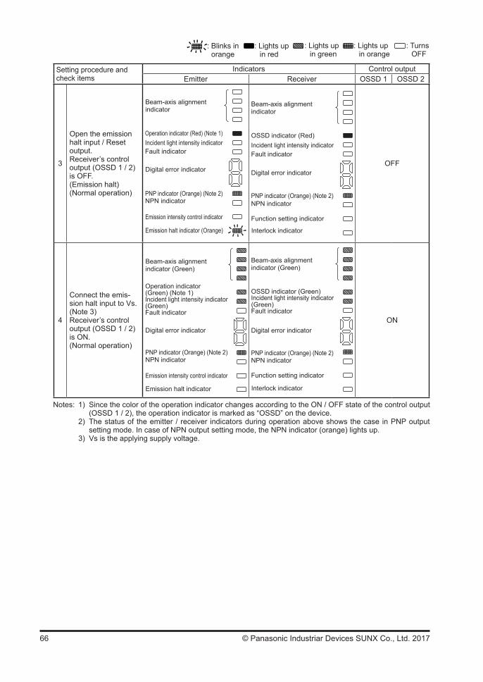
66 © Panasonic Industriar Devices SUNX Co., Ltd. 2017
: Blinks in orange
: Lights up in red
: Lights up in green
: Lights up in orange
: TurnsOFF
Setting procedure and check items
Indicators Control outputEmitter Receiver OSSD 1 OSSD 2
3
Open the emission halt input / Reset output.Receiver’s control output (OSSD 1 / 2) is OFF.(Emission halt) (Normal operation)
Beam-axis alignment indicator
PNP indicator (Orange) (Note 2)
Emission halt indicator (Orange)
Operation indicator (Red) (Note 1)Incident light intensity indicatorFault indicator
Digital error indicator
NPN indicator
Emission intensity control indicator
Interlock indicator
Function setting indicator
Beam-axis alignment indicator
PNP indicator (Orange) (Note 2)
OSSD indicator (Red)Incident light intensity indicatorFault indicator
Digital error indicator
NPN indicator
OFF
4
Connect the emis-sion halt input to Vs. (Note 3) Receiver’s control output (OSSD 1 / 2) is ON.(Normal operation)
Beam-axis alignment indicator (Green)
PNP indicator (Orange) (Note 2)
Emission halt indicator
Operation indicator (Green) (Note 1)Incident light intensity indicator
Fault indicator(Green)
Digital error indicator
NPN indicator
Emission intensity control indicator
Interlock indicator
Function setting indicator
Beam-axis alignment indicator (Green)
PNP indicator (Orange) (Note 2)
OSSD indicator (Green)Incident light intensity indicator
Fault indicator
Digital error indicator
NPN indicator
(Green)
ON
Notes: 1) Since the color of the operation indicator changes according to the ON / OFF state of the control output (OSSD 1 / 2), the operation indicator is marked as “OSSD” on the device.
2) The status of the emitter / receiver indicators during operation above shows the case in PNP output setting mode. In case of NPN output setting mode, the NPN indicator (orange) lights up.
3) Vs is the applying supply voltage.

67© Panasonic Industriar Devices SUNX Co., Ltd. 2017
3) When an error occursIf a device error is detected, the device will turn the control output (OSSD 1 / 2) OFF. Then the digital error indicator (red) on the receiver lights up and the fault indicators (yellow) on the emit-ter and receiver light up or blink.
If an emitter error is detected, the emitter will be locked out, stopping its emission, and the control output (OSSD 1 / 2) will be turned OFF.
If a receiver error is detected, the receiver will be locked out, and the control output (OSSD 1 / 2) will go into OFF state. Also, the emission halt indicator (orange) of the emitter lights up.
<Emitter> <Receiver>
Beam-axis alignment indicator
PNP indicator (Orange) (Note 3)
Emission halt indicator (Orange)
Operation indicator (Note 1)Incident light intensity indicatorFault indicator (Yellow)
Digital error indicator(Red) (Note 2)
NPN indicator
Emission intensity controlindicator
Interlock indicator
Function setting indicator
Beam-axis alignment indicator
PNP indicator (Orange) (Note 3)
OSSD indicatorIncident light intensity indicatorFault indicator (Yellow)
NPN indicator
Digital error indicator(Red) (Note 2)
: Blinks in yellow
: Lights up in red
: Lights up in orange
: TurnsOFF
Notes: 1) Since the color of the operation indicator changes according to the ON / OFF state of the control output (OSSD 1 / 2), the operation indicator is marked as “OSSD” on the device.
2) Refer to “Chapter 5 Troubleshooting” for details of the digital error indicator. 3) The status of the emitter / receiver indicators during operation above shows the case in PNP
output setting mode. In case of NPN output setting mode, the NPN indicator (orange) lights up.
Since this device will not return to normal operation automatically after the removal of the source of error, it is necessary to turn the power OFF and ON again.(Source of error): The control output (OSSD 1 / 2) short-circuit, extraneous light detection,
sensor failure, etc.Refer to “Chapter 5 Troubleshooting” and remove the source of error.
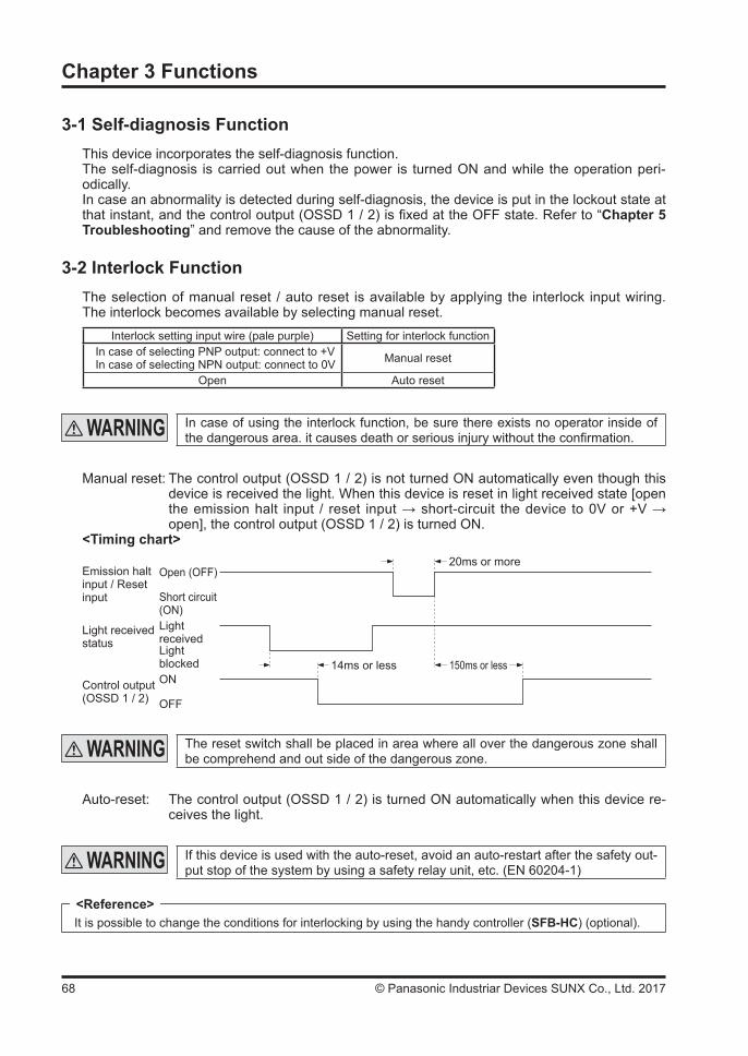
68 © Panasonic Industriar Devices SUNX Co., Ltd. 2017
Chapter 3 Functions
3-1 Self-diagnosis FunctionThis device incorporates the self-diagnosis function.The self-diagnosis is carried out when the power is turned ON and while the operation peri-odically.In case an abnormality is detected during self-diagnosis, the device is put in the lockout state at that instant, and the control output (OSSD 1 / 2) is fixed at the OFF state. Refer to “Chapter 5 Troubleshooting” and remove the cause of the abnormality.
3-2 Interlock FunctionThe selection of manual reset / auto reset is available by applying the interlock input wiring. The interlock becomes available by selecting manual reset.
Interlock setting input wire (pale purple) Setting for interlock functionIn case of selecting PNP output: connect to +VIn case of selecting NPN output: connect to 0V Manual reset
Open Auto reset
In case of using the interlock function, be sure there exists no operator inside of the dangerous area. it causes death or serious injury without the confirmation.
Manual reset: The control output (OSSD 1 / 2) is not turned ON automatically even though this device is received the light. When this device is reset in light received state [open the emission halt input / reset input → short-circuit the device to 0V or +V → open], the control output (OSSD 1 / 2) is turned ON.
<Timing chart>
Open (OFF)
Short circuit (ON)LightreceivedLight blockedON
OFF
Emission halt input / Reset input
Light received status
Control output(OSSD 1 / 2)
14ms or less
20ms or more
150ms or less
The reset switch shall be placed in area where all over the dangerous zone shall be comprehend and out side of the dangerous zone.
Auto-reset: The control output (OSSD 1 / 2) is turned ON automatically when this device re-ceives the light.
If this device is used with the auto-reset, avoid an auto-restart after the safety out-put stop of the system by using a safety relay unit, etc. (EN 60204-1)
It is possible to change the conditions for interlocking by using the handy controller (SFB-HC) (optional).<Reference>

69© Panasonic Industriar Devices SUNX Co., Ltd. 2017
3-3 Emission Halt FunctionThis function stops the emission process of the emitter.With the emission halt input line state, it enables to select either emission or emission halt.
Setting status of interlock function Emission halt input / Reset input Emission
halt input Control output (OSSD 1 / 2) status
Manual resetOpen Invalid ON
When selecting PNP output: connect to +VWhen selecting NPN output: connect to 0V Valid OFF
Auto resetOpen Valid OFF
When selecting PNP output: connect to +VWhen selecting NPN output: connect to 0V Invalid ON
During emission halt, the control output (OSSD 1 / 2) becomes OFF state.By using this function, malfunction due to extraneous noise or abnormality in the control output (OSSD 1 / 2) and the auxiliary output can be determined even from the equipment side.Normal operation is restored when the emission halt input / reset input is connected to 0V or +V (for manual reset: open).
20ms or less
ON
OFF
14ms or less 90ms or less
Emission halt input / Reset input
Emission status (Note 1)
Control output(OSSD 1 / 2)
Open
Short circuit
EmissionEmissionhalt
20ms or less
Note: This timing chart shows the operation in auto-reset mode. In manual reset mode, the device performs emis-sion under open status and performs emission halt under short-circuit status.
Do not use the emission halt function for the purpose of stopping the machine in which the SF4B<V2> series is installed. Failure to do so could result in death or serious injury.
3-4 Interference Prevention FunctionIt is possible to construct the system to prevent malfunction due to interference of the light between SF4B<V2> series devices.The interference prevention system can construct max. three sets of series and parallel mixed connection.The max. number of the beam channels in series and parallel mixed connection is 192.
Refer to “2-5 Wiring” for details of the connecting method.
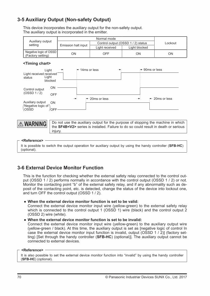
70 © Panasonic Industriar Devices SUNX Co., Ltd. 2017
3-5 Auxiliary Output (Non-safety Output)This device incorporates the auxiliary output for the non-safety output.The auxiliary output is incorporated in the emitter.
Auxiliary output setting
Normal modeLockout
Emission halt inputControl output (OSSD 1 / 2) status
Light received Light blockedNegative logic of OSSD (Factory setting) ON OFF ON ON
<Timing chart>
ON
OFF
ON
OFF
Auxiliary output Negative logic of OSSD
20ms or less
Light received status
Control output(OSSD 1 / 2)
Lightblocked
Lightreceived
14ms or less 90ms or less
20ms or less
Do not use the auxiliary output for the purpose of stopping the machine in which the SF4B<V2> series is installed. Failure to do so could result in death or serious injury.
It is possible to switch the output operation for auxiliary output by using the handy controller (SFB-HC) (optional).
3-6 External Device Monitor FunctionThis is the function for checking whether the external safety relay connected to the control out-put (OSSD 1 / 2) performs normally in accordance with the control output (OSSD 1 / 2) or not. Monitor the contacting point “b” of the external safety relay, and if any abnormality such as de-posit of the contacting point, etc. is detected, change the status of the device into lockout one, and turn OFF the control output (OSSD 1 / 2).
When the external device monitor function is set to be valid:Connect the external device monitor input wire (yellow-green) to the external safety relay which is connected to the control output 1 (OSSD 1) wire (black) and the control output 2 (OSSD 2) wire (white).
When the external device monitor function is set to be invalid:Connect the external device monitor input wire (yellow-green) to the auxiliary output wire (yellow-green / black). At this time, the auxiliary output is set as [negative logic of control In case the external device monitor input function is invalid, output (OSSD 1 / 2)] (factory set-ting) [Set through the handy controller (SFB-HC) (optional)]. The auxiliary output cannot be connected to external devices.
It is also possible to set the external device monitor function into “invalid” by using the handy controller (SFB-HC) (optional).
<Reference>
<Reference>

71© Panasonic Industriar Devices SUNX Co., Ltd. 2017
<Timing chart (Normal)>14ms or less 90ms or less
ON
OFF
ON
OFF
300ms or less
Lightblocked
Lightreceived
External device monitor input
Light received status
Control output(OSSD 1 / 2)
300ms or less
The setting time of the device monitor is 300ms or less. Exceeding 300ms turns the device into lockout status. It can be set within 100 to 600ms (unit: 10ms) by using the handy controller (SFB-HC) (optional).<Timing chart (Error 1)>
14ms or less
ON
OFF
ON
OFF
300ms
Lockout state
Lightblocked
Lightreceived
External device monitor input
Light received status
Control output(OSSD 1 / 2)
<Timing chart (Error 2)>90ms or less
External device monitor input
ON
OFF
ON
OFF
300ms
Lightblocked
Lightreceived Light received
status
Control output(OSSD 1 / 2)
Lockout state
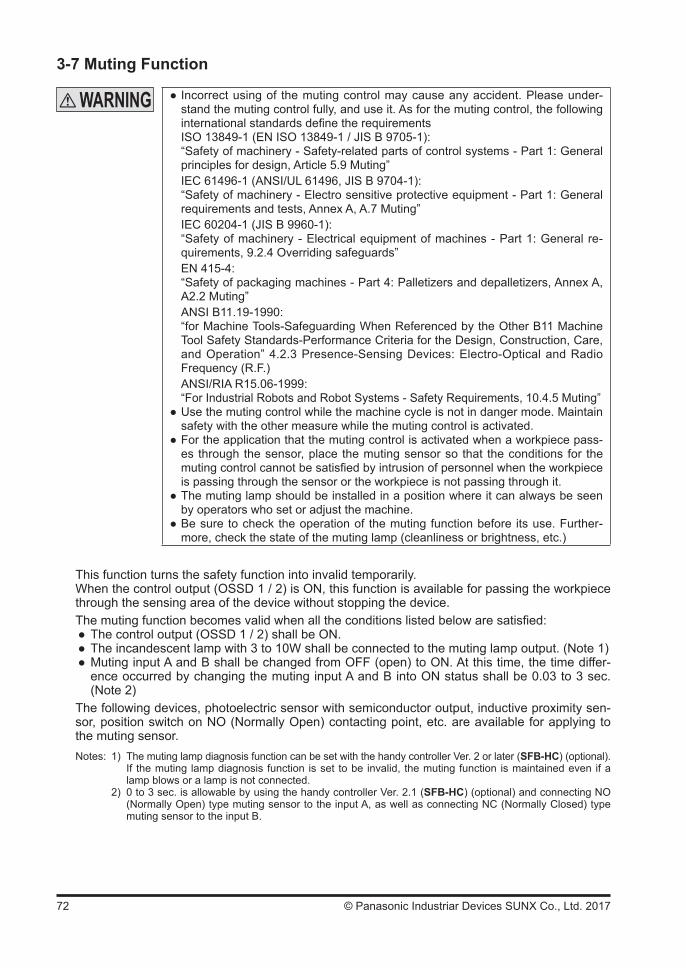
72 © Panasonic Industriar Devices SUNX Co., Ltd. 2017
3-7 Muting Function
Incorrect using of the muting control may cause any accident. Please under-stand the muting control fully, and use it. As for the muting control, the following international standards define the requirementsISO 13849-1 (EN ISO 13849-1 / JIS B 9705-1):“Safety of machinery - Safety-related parts of control systems - Part 1: General principles for design, Article 5.9 Muting”IEC 61496-1 (ANSI/UL 61496, JIS B 9704-1):“Safety of machinery - Electro sensitive protective equipment - Part 1: General requirements and tests, Annex A, A.7 Muting”IEC 60204-1 (JIS B 9960-1):“Safety of machinery - Electrical equipment of machines - Part 1: General re-quirements, 9.2.4 Overriding safeguards”EN 415-4:“Safety of packaging machines - Part 4: Palletizers and depalletizers, Annex A, A2.2 Muting”ANSI B11.19-1990:“for Machine Tools-Safeguarding When Referenced by the Other B11 Machine Tool Safety Standards-Performance Criteria for the Design, Construction, Care, and Operation” 4.2.3 Presence-Sensing Devices: Electro-Optical and Radio Frequency (R.F.)ANSI/RIA R15.06-1999:“For Industrial Robots and Robot Systems - Safety Requirements, 10.4.5 Muting”
Use the muting control while the machine cycle is not in danger mode. Maintain safety with the other measure while the muting control is activated.
For the application that the muting control is activated when a workpiece pass-es through the sensor, place the muting sensor so that the conditions for the muting control cannot be satisfied by intrusion of personnel when the workpiece is passing through the sensor or the workpiece is not passing through it.
The muting lamp should be installed in a position where it can always be seen by operators who set or adjust the machine.
Be sure to check the operation of the muting function before its use. Further-more, check the state of the muting lamp (cleanliness or brightness, etc.)
This function turns the safety function into invalid temporarily.When the control output (OSSD 1 / 2) is ON, this function is available for passing the workpiece through the sensing area of the device without stopping the device.The muting function becomes valid when all the conditions listed below are satisfied:
The control output (OSSD 1 / 2) shall be ON. The incandescent lamp with 3 to 10W shall be connected to the muting lamp output. (Note 1) Muting input A and B shall be changed from OFF (open) to ON. At this time, the time differ-ence occurred by changing the muting input A and B into ON status shall be 0.03 to 3 sec. (Note 2)
The following devices, photoelectric sensor with semiconductor output, inductive proximity sen-sor, position switch on NO (Normally Open) contacting point, etc. are available for applying to the muting sensor.Notes: 1) The muting lamp diagnosis function can be set with the handy controller Ver. 2 or later (SFB-HC) (optional). If the muting lamp diagnosis function is set to be invalid, the muting function is maintained even if a
lamp blows or a lamp is not connected. 2) 0 to 3 sec. is allowable by using the handy controller Ver. 2.1 (SFB-HC) (optional) and connecting NO
(Normally Open) type muting sensor to the input A, as well as connecting NC (Normally Closed) type muting sensor to the input B.
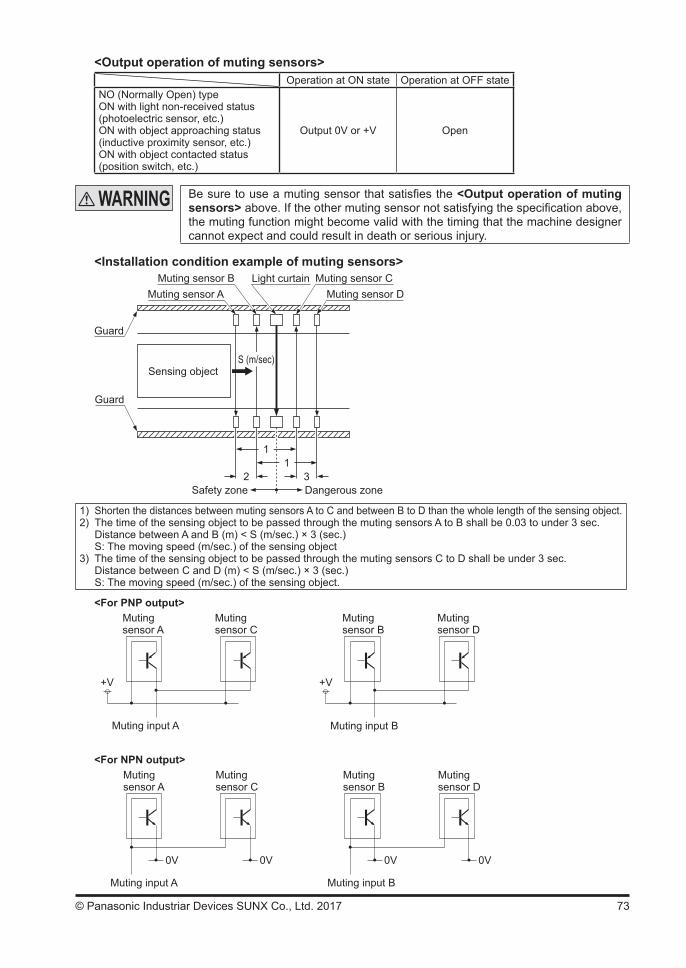
73© Panasonic Industriar Devices SUNX Co., Ltd. 2017
<Output operation of muting sensors>Operation at ON state Operation at OFF state
NO (Normally Open) typeON with light non-received status (photoelectric sensor, etc.)ON with object approaching status (inductive proximity sensor, etc.)ON with object contacted status (position switch, etc.)
Output 0V or +V Open
Be sure to use a muting sensor that satisfies the <Output operation of muting sensors> above. If the other muting sensor not satisfying the specification above, the muting function might become valid with the timing that the machine designer cannot expect and could result in death or serious injury.
<Installation condition example of muting sensors>Light curtain Muting sensor C
Muting sensor DMuting sensor B
Muting sensor A
Sensing objectS (m/sec)
11
2 3Safety zone Dangerous zone
Guard
Guard
1) Shorten the distances between muting sensors A to C and between B to D than the whole length of the sensing object.2) The time of the sensing object to be passed through the muting sensors A to B shall be 0.03 to under 3 sec. Distance between A and B (m) < S (m/sec.) × 3 (sec.) S: The moving speed (m/sec.) of the sensing object3) The time of the sensing object to be passed through the muting sensors C to D shall be under 3 sec. Distance between C and D (m) < S (m/sec.) × 3 (sec.) S: The moving speed (m/sec.) of the sensing object.
<For PNP output>Muting sensor A
+V
Muting input A
<For NPN output>
0V
Muting input A
0V
+V
Muting input B
0V
Muting input B
0V
Muting sensor D
Muting sensor B
Muting sensor C
Muting sensor A
Muting sensor D
Muting sensor B
Muting sensor C
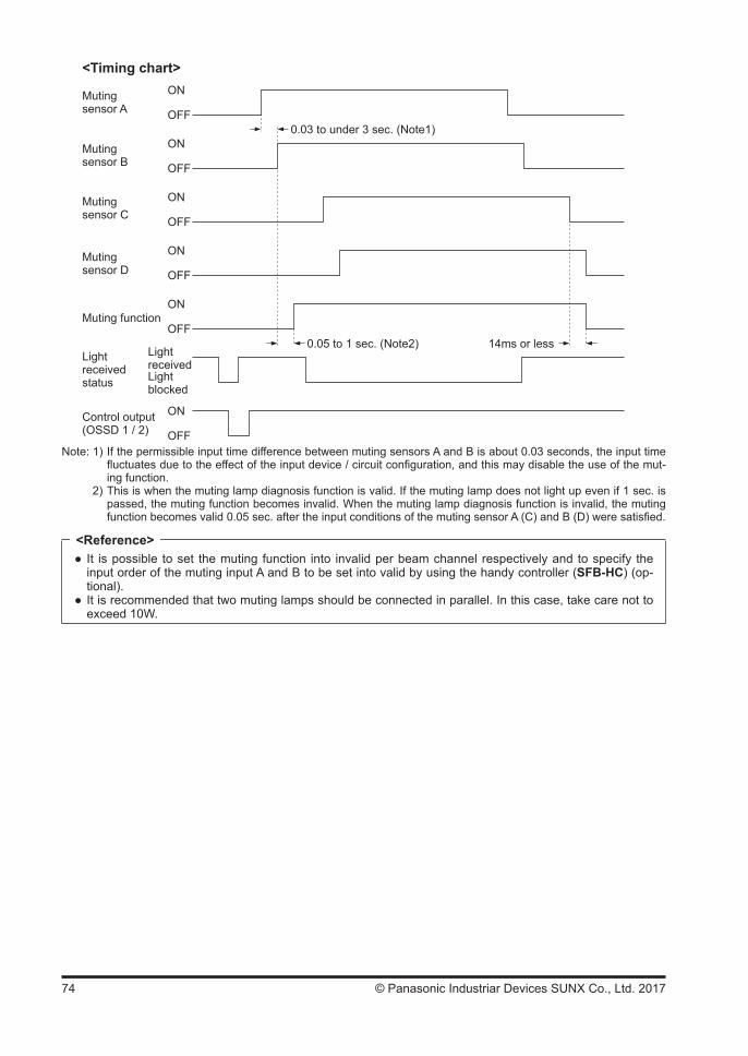
74 © Panasonic Industriar Devices SUNX Co., Ltd. 2017
<Timing chart>ON
OFF
ON
OFF
ON
OFF
0.03 to under 3 sec. (Note1)
ON
OFFControl output(OSSD 1 / 2)
Light receivedstatus
ON
OFF
ON
OFFMuting function
0.05 to 1 sec. (Note2) 14ms or less
Muting sensor A
Muting sensor D
Muting sensor C
Muting sensor B
Lightblocked
Lightreceived
Note: 1) If the permissible input time difference between muting sensors A and B is about 0.03 seconds, the input time fluctuates due to the effect of the input device / circuit configuration, and this may disable the use of the mut-ing function.
2) This is when the muting lamp diagnosis function is valid. If the muting lamp does not light up even if 1 sec. is passed, the muting function becomes invalid. When the muting lamp diagnosis function is invalid, the muting function becomes valid 0.05 sec. after the input conditions of the muting sensor A (C) and B (D) were satisfied.
It is possible to set the muting function into invalid per beam channel respectively and to specify the input order of the muting input A and B to be set into valid by using the handy controller (SFB-HC) (op-tional).
It is recommended that two muting lamps should be connected in parallel. In this case, take care not to exceed 10W.
<Reference>
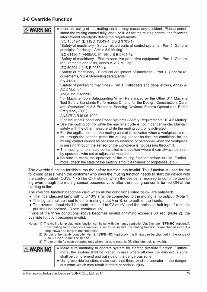
75© Panasonic Industriar Devices SUNX Co., Ltd. 2017
3-8 Override Function
Incorrect using of the muting control may cause any accident. Please under-stand the muting control fully, and use it. As for the muting control, the following international standards define the requirementsISO 13849-1 (EN ISO 13849-1, JIS B 9705-1):“Safety of machinery - Safety-related parts of control systems - Part 1: General principles for design, Article 5.9 Muting”IEC 61496-1 (ANSI/UL 61496, JIS B 9704-1):“Safety of machinery - Electro sensitive protective equipment - Part 1: General requirements and tests, Annex A, A.7 Muting”IEC 60204-1 (JIS B 9960-1):“Safety of machinery - Electrical equipment of machines - Part 1: General re-quirements, 9.2.4 Overriding safeguards”EN 415-4:“Safety of packaging machines - Part 4: Palletizers and depalletizers, Annex A, A2.2 Muting”ANSI B11.19-1990:“for Machine Tools-Safeguarding When Referenced by the Other B11 Machine Tool Safety Standards-Performance Criteria for the Design, Construction, Care, and Operation” 4.2.3 Presence-Sensing Devices: Electro-Optical and Radio Frequency (R.F.)ANSI/RIA R15.06-1999:“For Industrial Robots and Robot Systems - Safety Requirements, 10.4.5 Muting”
Use the muting control while the machine cycle is not in danger mode. Maintain safety with the other measure while the muting control is activated.
For the application that the muting control is activated when a workpiece pass-es through the sensor, place the muting sensor so that the conditions for the muting control cannot be satisfied by intrusion of personnel when the workpiece is passing through the sensor or the workpiece is not passing through it.
The muting lamp should be installed in a position where it can always be seen by operators who set or adjust the machine.
Be sure to check the operation of the muting function before its use. Further-more, check the state of the muting lamp (cleanliness or brightness, etc.)
The override function forcibly turns the safety function into invalid. This function is used for the following cases: when the customer who uses the muting function needs to start the device with the control output (OSSD 1 / 2) be OFF status, when the device is required to continue operat-ing even though the muting sensor becomes valid after the muting sensor is turned ON at the starting of line.The override function becomes valid when all the conditions listed below are satisfied:
The incandescent lamp with 3 to 10W shall be connected to the muting lamp output. (Note 1) The signal shall be input to either muting input A or B, or to both of the inputs. The override input shall be short-circuited to 0V or +V, and the emission halt input / reset in-put shall be opened. (3 sec. continuously)
If one of the three conditions above becomes invalid or timing exceeds 60 sec. (Note 2), the override function becomes invalid.Notes: 1) The muting lamp diagnosis function can be set with the handy controller Ver. 2 or later (SFB-HC) (optional). If the muting lamp diagnosis function is set to be invalid, the muting function is maintained even if a
lamp blows or a lamp is not connected. 2) By using the handy controller Ver. 2.1 (SFB-HC) (optional), the timing can be changed in the range of
60 to 600 sec. in units of 10 sec. 3) The override function operates only when the auto-reset is ON (the interlock is invalid).
Make sure manually to operate system for starting override function. Further-more, the system shall be placed in area where all over the dangerous zone shall be comprehend and out side of the dangerous zone.
Using override function, make sure that there exist no operator in the danger-ous zone, which may result in death or serious injury.
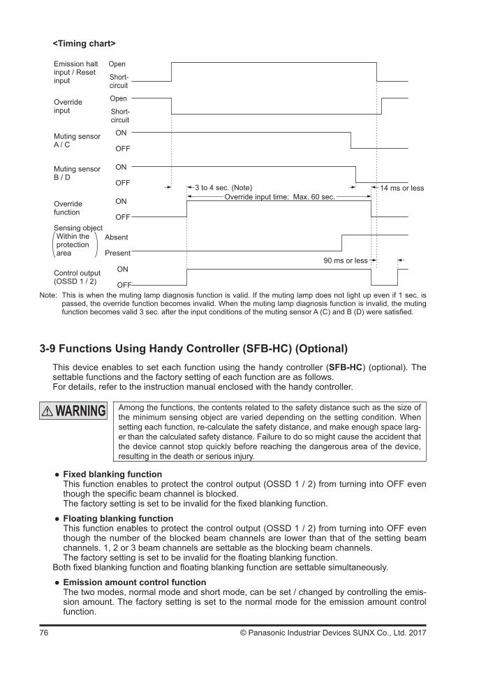
76 © Panasonic Industriar Devices SUNX Co., Ltd. 2017
<Timing chart>
ON
OFF
ON
OFF
ON
OFF
Open
Short-circuit
Emission halt input / Reset input
Open
Short-circuit
Override input
Muting sensor B / D
Muting sensor A / C
Overridefunction
ON
OFF
Absent
Present
Control output(OSSD 1 / 2)
Sensing objectWithin the protection area
3 to 4 sec. (Note)Override input time: Max. 60 sec.
14 ms or less
90 ms or less
Note: This is when the muting lamp diagnosis function is valid. If the muting lamp does not light up even if 1 sec. is passed, the override function becomes invalid. When the muting lamp diagnosis function is invalid, the muting function becomes valid 3 sec. after the input conditions of the muting sensor A (C) and B (D) were satisfied.
3-9 Functions Using Handy Controller (SFB-HC) (Optional)This device enables to set each function using the handy controller (SFB-HC) (optional). The settable functions and the factory setting of each function are as follows.For details, refer to the instruction manual enclosed with the handy controller.
Among the functions, the contents related to the safety distance such as the size of the minimum sensing object are varied depending on the setting condition. When setting each function, re-calculate the safety distance, and make enough space larg-er than the calculated safety distance. Failure to do so might cause the accident that the device cannot stop quickly before reaching the dangerous area of the device, resulting in the death or serious injury.
Fixed blanking functionThis function enables to protect the control output (OSSD 1 / 2) from turning into OFF even though the specific beam channel is blocked.The factory setting is set to be invalid for the fixed blanking function.
Floating blanking functionThis function enables to protect the control output (OSSD 1 / 2) from turning into OFF even though the number of the blocked beam channels are lower than that of the setting beam channels. 1, 2 or 3 beam channels are settable as the blocking beam channels.The factory setting is set to be invalid for the floating blanking function.
Both fixed blanking function and floating blanking function are settable simultaneously.
Emission amount control functionThe two modes, normal mode and short mode, can be set / changed by controlling the emis-sion amount. The factory setting is set to the normal mode for the emission amount control function.
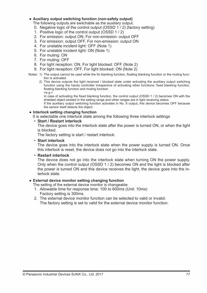
77© Panasonic Industriar Devices SUNX Co., Ltd. 2017
Auxiliary output switching function (non-safety output)The following outputs are switchable as the auxiliary output.0. Negative logic of the control output (OSSD 1 / 2) (factory setting)1. Positive logic of the control output (OSSD 1 / 2)2. For emission: output ON, For non-emission: output OFF3. For emission: output OFF, For non-emission: output ON4. For unstable incident light: OFF (Note 1)5. For unstable incident light: ON (Note 1)6. For muting: ON7. For muting: OFF8. For light reception: ON, For light blocked: OFF (Note 2)9. For light reception: OFF, For light blocked: ON (Note 2)
Notes: 1) The output cannot be used while the fix blanking function, floating blanking function or the muting func-tion is activated.
2) This device outputs the light received / blocked state under activating the auxiliary output switching function using the handy controller irrespective of activating other functions: fixed blanking function, floating blanking function and muting function.
<e.g.> In case of activating the fixed blanking function, the control output (OSSD 1 / 2) becomes ON with the
shielded object existed in the setting range and other ranges are in light receiving status. If the auxiliary output switching function activates in No. 8 output, this device becomes OFF because
the sensor itself detects the object. Interlock setting changing functionIt is selectable one interlock state among the following three interlock settings• Start / Restart interlock
The device goes into the interlock state after the power is turned ON, or when the light is blocked.The factory setting is start / restart interlock.
• Start interlockThe device goes into the interlock state when the power supply is turned ON. Once this interlock is reset, the device does not go into the interlock state.
• Restart interlockThe device does not go into the interlock state when turning ON the power supply. Only when the control output (OSSD 1 / 2) becomes ON and the light is blocked after the power is turned ON and this device receives the light, the device goes into the in-terlock state.
External device monitor setting changing functionThe setting of the external device monitor is changeable.1. Allowable time for response time: 100 to 600ms (Unit: 10ms) Factory setting is 300ms.2. The external device monitor function can be selected to valid or invalid. The factory setting is set to valid for the external device monitor function.
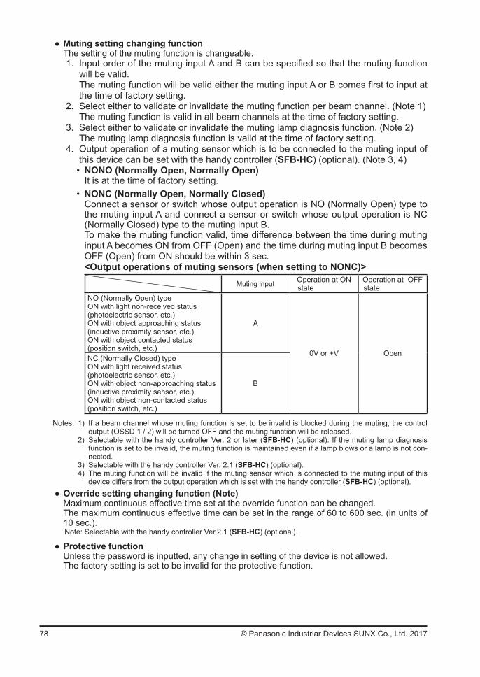
78 © Panasonic Industriar Devices SUNX Co., Ltd. 2017
Muting setting changing functionThe setting of the muting function is changeable.1. Input order of the muting input A and B can be specified so that the muting function
will be valid. The muting function will be valid either the muting input A or B comes first to input at
the time of factory setting. 2. Select either to validate or invalidate the muting function per beam channel. (Note 1) The muting function is valid in all beam channels at the time of factory setting.3. Select either to validate or invalidate the muting lamp diagnosis function. (Note 2) The muting lamp diagnosis function is valid at the time of factory setting.4. Output operation of a muting sensor which is to be connected to the muting input of
this device can be set with the handy controller (SFB-HC) (optional). (Note 3, 4)• NONO (Normally Open, Normally Open)
It is at the time of factory setting.• NONC (Normally Open, Normally Closed)
Connect a sensor or switch whose output operation is NO (Normally Open) type to the muting input A and connect a sensor or switch whose output operation is NC (Normally Closed) type to the muting input B.To make the muting function valid, time difference between the time during muting input A becomes ON from OFF (Open) and the time during muting input B becomes OFF (Open) from ON should be within 3 sec. <Output operations of muting sensors (when setting to NONC)>
Muting input Operation at ONstate
Operation at OFFstate
NO (Normally Open) typeON with light non-received status (photoelectric sensor, etc.)ON with object approaching status (inductive proximity sensor, etc.)ON with object contacted status(position switch, etc.)
A
0V or +V OpenNC (Normally Closed) typeON with light received status (photoelectric sensor, etc.)ON with object non-approaching status (inductive proximity sensor, etc.)ON with object non-contacted status (position switch, etc.)
B
Notes: 1) If a beam channel whose muting function is set to be invalid is blocked during the muting, the control output (OSSD 1 / 2) will be turned OFF and the muting function will be released.
2) Selectable with the handy controller Ver. 2 or later (SFB-HC) (optional). If the muting lamp diagnosis function is set to be invalid, the muting function is maintained even if a lamp blows or a lamp is not con-nected.
3) Selectable with the handy controller Ver. 2.1 (SFB-HC) (optional). 4) The muting function will be invalid if the muting sensor which is connected to the muting input of this
device differs from the output operation which is set with the handy controller (SFB-HC) (optional). Override setting changing function (Note)Maximum continuous effective time set at the override function can be changed. The maximum continuous effective time can be set in the range of 60 to 600 sec. (in units of 10 sec.).
Note: Selectable with the handy controller Ver.2.1 (SFB-HC) (optional).
Protective functionUnless the password is inputted, any change in setting of the device is not allowed.The factory setting is set to be invalid for the protective function.
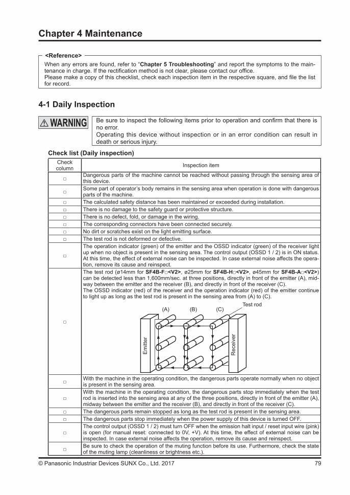
79© Panasonic Industriar Devices SUNX Co., Ltd. 2017
Chapter 4 Maintenance
When any errors are found, refer to “Chapter 5 Troubleshooting” and report the symptoms to the main-tenance in charge. If the rectification method is not clear, please contact our office. Please make a copy of this checklist, check each inspection item in the respective square, and file the list for record.
4-1 Daily Inspection
Be sure to inspect the following items prior to operation and confirm that there is no error. Operating this device without inspection or in an error condition can result in death or serious injury.
Check list (Daily inspection)Check column Inspection item
Dangerous parts of the machine cannot be reached without passing through the sensing area of this device.
Some part of operator’s body remains in the sensing area when operation is done with dangerous parts of the machine.
The calculated safety distance has been maintained or exceeded during installation. There is no damage to the safety guard or protective structure. There is no defect, fold, or damage in the wiring. The corresponding connectors have been connected securely. No dirt or scratches exist on the light emitting surface. The test rod is not deformed or defective.
The operation indicator (green) of the emitter and the OSSD indicator (green) of the receiver light up when no object is present in the sensing area. The control output (OSSD 1 / 2) is in ON status.At this time, the effect of external noise can be inspected. In case external noise affects the opera-tion, remove its cause and reinspect.
The test rod (ø14mm for SF4B-F<V2>, ø25mm for SF4B-H<V2>, ø45mm for SF4B-A<V2>) can be detected less than 1,600mm/sec. at three positions, directly in front of the emitter (A), mid-way between the emitter and the receiver (B), and directly in front of the receiver (C).The OSSD indicator (red) of the receiver and the operation indicator (red) of the emitter continue to light up as long as the test rod is present in the sensing area from (A) to (C).
Test rod(A) (B) (C)
Em
itter
Rec
eive
r
With the machine in the operating condition, the dangerous parts operate normally when no object is present in the sensing area.
With the machine in the operating condition, the dangerous parts stop immediately when the test rod is inserted into the sensing area at any of the three positions, directly in front of the emitter (A), midway between the emitter and the receiver (B), and directly in front of the receiver (C).
The dangerous parts remain stopped as long as the test rod is present in the sensing area. The dangerous parts stop immediately when the power supply of this device is turned OFF.
The control output (OSSD 1 / 2) must turn OFF when the emission halt input / reset input wire (pink) is open (for manual reset: connected to 0V, +V). At this time, the effect of external noise can be inspected. In case external noise affects the operation, remove its cause and reinspect.
Be sure to check the operation of the muting function before its use. Furthermore, check the state of the muting lamp (cleanliness or brightness etc.).
<Reference>
80 © Panasonic Industriar Devices SUNX Co., Ltd. 2017
4-2 Periodic Inspection (Every Six Months)
Be sure to inspect the following items every six months and confirm that there is no error. Operating this device without inspection or in an error condition can re-sult in death or serious injury.
Check list (Periodic inspection)Check column Inspection item
The structure of the machine does not obstruct any safety mechanism for stopping operation. No modification has been made in the machine controls which obstructs the safety mechanisms. The output of this device is correctly detected. The wiring from this device is correct. The overall response time of the complete machine is equal or less than the calculated value.
The actual number of operation cycle (time) of the limited lifetime parts (relay, etc.) is less than their rated operation cycles (time).
No screws or connectors of this device are loose. No extraneous light source or reflective object has been added near this device.
4-3 Inspection after MaintenanceUnder the following situations, perform all the inspection items mentioned in “4-1 Daily Inspec-tion” and “4-2 Periodic Inspection (Every Six Months).”
1) When any parts of this device are replaced.2) When some abnormality is felt during operation.3) When beam-axis alignment of the emitter and receiver is done.4) When the device installation place or environment is changed.5) When the wiring method or wiring layout is changed.6) When FSD (Final Switching Device) parts are replaced.7) When FSD (Final Switching Device) setting is changed.
81© Panasonic Industriar Devices SUNX Co., Ltd. 2017
Chapter 5 Troubleshooting
Check the wiring. Check the power supply voltage and the power supply capacity.
5-1 Troubleshooting of Emitter<All indicators are OFF>
Cause Remedy
Power is not being supplied Check that the power supply capacity is sufficient.Connect the power supply correctly.
Supply voltage is out of the specified range. Set the supply voltage correctly.Connector is not connected securely. Connect the connector securely.
<Fault indicator (yellow) lights or blinks>Cause Remedy
[Digital error indicator: ]Setting data error of this device
Ser ies connect ion is in-correct.
Check that the cable for series connection does not short-circuit, or is connected to the correct po-sition (emitter for emitter, receiver for receivers).Incase the handy controller (SFB-HC) (optional) is applied, reset the function.
Noise is out of the specified range.
Check the noise status around this device. In case the handy controller (SFB-HC) (optional) is applied, reset the function.
Internal error Contact our office.[Digital error indicator: ]System error between emitter and receiver
Systems are different be-tween emitter and receiver.
Set the same value to the numbers of emitter and receiver and that of beam channel, and the shield wires.
[Digital error indicator: ]Series connection error
The serial signal short-circuits or comes down.
Check if the end cap has been fitted properly.Check that the cable for series connection does not short-circuit, or is connected to the correct position (emitter for emitter, receiver for receiver). Check the error contents of the device connected by the cable for series connection.
Any of the main / sub sensor is in error.
[Digital error indicator: ]No. of total units / No. of total beam channels error
No. of total units / No. of total beam channels is out of the specified range.
Set the condition of the series connection within the specification.Refer to “2-5-6 Series Connection.”
[Digital error indicator: ]Interlock setting error
Voltage level of interlock set-ting input wire (pale purple), or emission halt input / reset input wire (pink) is unstable.
Wire the interlock setting input wire (pale purple) and emission halt input / reset input wire (pink) correctly.
[Digital error indicator: , ]Muting lamp error
Muting lamp output wire (red) short-circuits with 0V or +V.
Wire the muting lamp output wires (red) correctly. Refer to “2-5 Wiring.”Current value should be within the specified mut-ing lamp output.
Muting lamp output wire (red) short-circuits with other I/O wires.Excessive incoming current flows in the muting lamp out-put.Output polarity setting wire (shield) and muting lamp output wire (red) are not cor-rectly wired.
Wire the output polarity setting wire (shield) cor-rectly. (0V: PNP output, +V: NPN output).Wire the muting lamp output wire (red) correctly.Refer to “2-5 Wiring.”
Output circuit error Output circuit is damaged. Replace this device.
<Reference>
82 © Panasonic Industriar Devices SUNX Co., Ltd. 2017
Cause Remedy
[Digital error indicator: ]Output polarity setting wire (shield) error
Output polarity setting wire (shield) comes down or short-circuits with other I/O wires. Output polarity setting wire (shield) connection of emitter / receiver is incorrect.
Wire the output polarity setting wire (shield) cor-rectly. (0V: PNP output, +V: NPN output)Wire the output polarity setting wire (shield) of the receiver correctly.
[Digital error indicator: ]Effect from noise / power supply or failure of internal circuit
Affected by noise / power supply.Internal circuit is broken down.
Check the noise status around this device.Check the wiring status, supply voltage, and power supply capacity.When the synchronization + wire (orange) and synchronization - wire (orange / black) is extend-ed with a cable other than exclusive cable, use a 0.2mm2 or more shielded twisted pair cable.If this device still does not work, confirm number of blinks of the error indicator and call to our local office.
<Digital error indicator “ ” lights up>Cause Remedy
Synchronization + wire (orange) or synchronization - wire (orange / black) error.Synchronization + wire (orange) or synchronization - wire (orange / black) comes down or short-circuits.
Connect synchronization + wire (orange) or syn-chronization + wire (orange / black) properly.Refer to “2-5 Wiring.”
Receiver error Check the operation of the receiver side.
<Emission halt indicator (orange) lights up>Cause Remedy
Emission is in halt condition (Device error or interlock set-ting error)
Error indicator (yellow) lights or blinks. Check the contents of the digital error indicator.
Emission halt input / reset in-put wire (pink) is open when selecting auto-reset.
Wire the emission halt input / reset input (pink) wire to 0V or +V.Refer to “2-5 Wiring.”
Emission halt input / reset input wire (pink) is connected to 0V or +V when selecting manual reset.
Open the emission halt input / reset input (pink) wire. Refer to “2-5 Wiring.”
<All beam-axis adjustment indicators (red) light up>Cause Remedy
The beam channel with its fixed blanking function set into valid receives light.
Turn ON the power supply after checking the in-stallation status.
<Operation indicator remains lit in red (light is not received) (Note)>Cause Remedy
The beam channels are not correctly aligned.
Align the beam channels.Refer to “2-6 Adjustment.”Align the top / bottom direction of the beam chan-nel between emitter and receiver.
Sensing range is shortened because of the emission amount control function.
Reset to factory default (CLR) by the handy con-troller (SFB-HC) (optional).
Note: Since the color of the operation indicator changes according to ON / OFF status of the control output (OSSD 1 / 2), the operation indicator is marked as “OSSD” on the device.
If the device does not work normally after checking the items above, please consult Panasonic Industrial Devices SUNX.
About counting blinks of the error indicator, count blinks from 2 seconds of no blinking.<Reference>
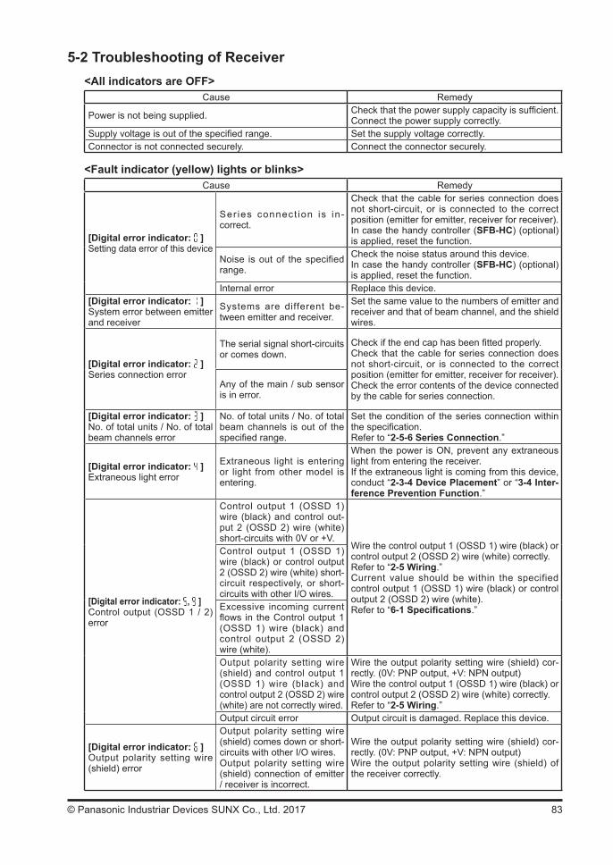
83© Panasonic Industriar Devices SUNX Co., Ltd. 2017
5-2 Troubleshooting of Receiver <All indicators are OFF>
Cause Remedy
Power is not being supplied. Check that the power supply capacity is sufficient.Connect the power supply correctly.
Supply voltage is out of the specified range. Set the supply voltage correctly.Connector is not connected securely. Connect the connector securely.
<Fault indicator (yellow) lights or blinks>Cause Remedy
[Digital error indicator: ]Setting data error of this device
Ser ies connect ion is in-correct.
Check that the cable for series connection does not short-circuit, or is connected to the correct position (emitter for emitter, receiver for receiver).In case the handy controller (SFB-HC) (optional) is applied, reset the function.
Noise is out of the specified range.
Check the noise status around this device.In case the handy controller (SFB-HC) (optional) is applied, reset the function.
Internal error Replace this device.[Digital error indicator: ]System error between emitter and receiver
Systems are different be-tween emitter and receiver.
Set the same value to the numbers of emitter and receiver and that of beam channel, and the shield wires.
[Digital error indicator: ]Series connection error
The serial signal short-circuits or comes down.
Check if the end cap has been fitted properly.Check that the cable for series connection does not short-circuit, or is connected to the correct position (emitter for emitter, receiver for receiver).Check the error contents of the device connected by the cable for series connection.
Any of the main / sub sensor is in error.
[Digital error indicator: ]No. of total units / No. of total beam channels error
No. of total units / No. of total beam channels is out of the specified range.
Set the condition of the series connection within the specification.Refer to “2-5-6 Series Connection.”
[Digital error indicator: ]Extraneous light error
Extraneous light is entering or light from other model is entering.
When the power is ON, prevent any extraneous light from entering the receiver.If the extraneous light is coming from this device, conduct “2-3-4 Device Placement” or “3-4 Inter-ference Prevention Function.”
[Digital error indicator: , ]Control output (OSSD 1 / 2) error
Control output 1 (OSSD 1) wire (black) and control out-put 2 (OSSD 2) wire (white) short-circuits with 0V or +V.
Wire the control output 1 (OSSD 1) wire (black) or control output 2 (OSSD 2) wire (white) correctly.Refer to “2-5 Wiring.”Current value should be within the specified control output 1 (OSSD 1) wire (black) or control output 2 (OSSD 2) wire (white).Refer to “6-1 Specifications.”
Control output 1 (OSSD 1) wire (black) or control output 2 (OSSD 2) wire (white) short-circuit respectively, or short-circuits with other I/O wires.Excessive incoming current flows in the Control output 1 (OSSD 1) wire (black) and control output 2 (OSSD 2) wire (white).Output polarity setting wire (shield) and control output 1 (OSSD 1) wire (black) and control output 2 (OSSD 2) wire (white) are not correctly wired.
Wire the output polarity setting wire (shield) cor-rectly. (0V: PNP output, +V: NPN output)Wire the control output 1 (OSSD 1) wire (black) or control output 2 (OSSD 2) wire (white) correctly.Refer to “2-5 Wiring.”
Output circuit error Output circuit is damaged. Replace this device.
[Digital error indicator: ]Output polarity setting wire (shield) error
Output polarity setting wire (shield) comes down or short-circuits with other I/O wires.Output polarity setting wire (shield) connection of emitter / receiver is incorrect.
Wire the output polarity setting wire (shield) cor-rectly. (0V: PNP output, +V: NPN output)Wire the output polarity setting wire (shield) of the receiver correctly.
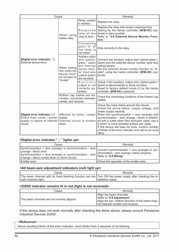
84 © Panasonic Industriar Devices SUNX Co., Ltd. 2017
Cause Remedy
[Digital error indicator: ]External device error
When using safety relay
Relay contact is welded. Replace the relay.
R e s p o n s e t ime o f t he relay is slow.
Replace the relay with proper response time.Setting by the handy controller (SFB-HC) (op-tional) is also possible.Refer to “3-6 External Device Monitor Func-tion.”
C o n t a c t i n g po in t “b” o f the re lay is not wired.
Wire correctly to the relay.
When setting the external device moni-tor function to “invalid.”
Auxiliary output wire (yel low-green / black) and external device moni-tor input wire (yellow-green) are not wired.
Connect the auxiliary output wire (yellow-green / black) and the external device monitor input wire (yellow-green).Set the external device monitor function to “in-valid” using the handy controller (SFB-HC) (op-tional).
A u x i l i a r y output is not correctly op-erated.
Check if the auxiliary output wire (yellow-green / black) is disconnected or short-circuited.Reset to factory default (mode 0) by the handy controller (SFB-HC) (optional).
Bottom cap cables are ad-versely connected between emitter and receiver.
Check the connecting locations of the bottom cap cables.
[Digital error indicator: ]Effect from noise / power supply or failure of internal circuit
Affected by noise / power supply.Internal circuit is broken down.
Check the noise status around this device.Check the wiring status, supply voltage, and power supply capacity.When the synchronization + wire (orange) and synchronization - wire (orange / black) is extend-ed with a cable other than exclusive cable, use a 0.2mm2 or more shielded twisted pair cable.If this device still does not work, confirm number of blinks of the error indicator and call to our local office.
<Digital error indicator “ ” lights up>Cause Remedy
Synchronization + wire (orange) or synchronization - wire (orange / black) error.Synchronization + wire (orange) or synchronization - wire (orange / black) comes down or short-circuits.
Connect synchronization + wire (orange) or syn-chronization - wire (orange / black) properly.Refer to “2-5 Wiring.”
Emitter error Check the operation of the emitter side.
<All beam-axis adjustment indicators (red) light up>Cause Remedy
The beam channel with its fixed blanking function set into valid receives light.
Turn ON the power supply after checking the in-stallation status.
<OSSD indicator remains lit in red (light is not received)>Cause Remedy
The beam channels are not correctly aligned.
Align the beam channels.Refer to “2-6 Adjustment.”Align the top / bottom direction of the beam chan-nel between emitter and receiver.
If the device does not work normally after checking the items above, please consult Panasonic Industrial Devices SUNX.
About counting blinks of the error indicator, count blinks from 2 seconds of no blinking.<Reference>
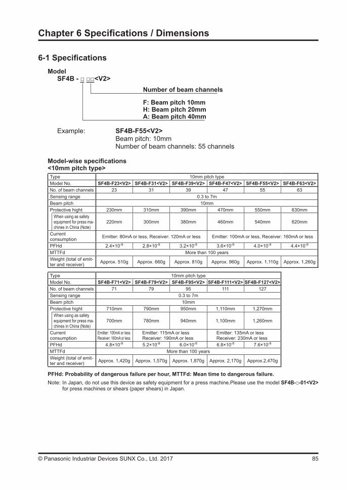
85© Panasonic Industriar Devices SUNX Co., Ltd. 2017
Chapter 6 Specifications / Dimensions
6-1 SpecificationsModel
SF4B - <V2>Number of beam channels
F: Beam pitch 10mmH: Beam pitch 20mmA: Beam pitch 40mm
Example: SF4B-F55<V2> Beam pitch: 10mm
Number of beam channels: 55 channels
Model-wise specifications<10mm pitch type>Type 10mm pitch typeModel No. SF4B-F23<V2> SF4B-F31<V2> SF4B-F39<V2> SF4B-F47<V2> SF4B-F55<V2> SF4B-F63<V2>No. of beam channels 23 31 39 47 55 63Sensing range 0.3 to 7mBeam pitch 10mmProtective hight 230mm 310mm 390mm 470mm 550mm 630mm
When using as safety equipment for press ma-chines in China (Note)
220mm 300mm 380mm 460mm 540mm 620mm
Current consumption Emitter: 80mA or less, Receiver: 120mA or less Emitter: 100mA or less, Receiver: 160mA or less
PFHd 2.4×10⁻⁹ 2.8×10⁻⁹ 3.2×10⁻⁹ 3.6×10⁻⁹ 4.0×10⁻⁹ 4.4×10⁻⁹
MTTFd More than 100 yearsWeight (total of emit-ter and receiver) Approx. 510g Approx. 660g Approx. 810g Approx. 960g Approx. 1,110g Approx. 1,260g
Type 10mm pitch typeModel No. SF4B-F71<V2> SF4B-F79<V2> SF4B-F95<V2> SF4B-F111<V2> SF4B-F127<V2>No. of beam channels 71 79 95 111 127Sensing range 0.3 to 7mBeam pitch 10mmProtective hight 710mm 790mm 950mm 1,110mm 1,270mm
When using as safety equipment for press ma-chines in China (Note)
700mm 780mm 940mm 1,100mm 1,260mm
Current consumption
Emitter: 100mA or lessReceiver: 160mA or less
Emitter: 115mA or lessReceiver: 190mA or less
Emitter: 135mA or lessReceiver: 230mA or less
PFHd 4.8×10⁻⁹ 5.2×10⁻⁹ 6.0×10⁻⁹ 6.8×10⁻⁹ 7.6×10⁻⁹
MTTFd More than 100 yearsWeight (total of emit-ter and receiver) Approx. 1,420g Approx. 1,570g Approx. 1,870g Approx. 2,170g Approx.2,470g
PFHd: Probability of dangerous failure per hour, MTTFd: Mean time to dangerous failure.Note: In Japan, do not use this device as safety equipment for a press machine.Please use the model SF4B--01<V2>
for press machines or shears (paper shears) in Japan.

86 © Panasonic Industriar Devices SUNX Co., Ltd. 2017
<20mm pitch type>Type 20mm pitch typeModel No. SF4B-H12<V2> SF4B-H16<V2> SF4B-H20<V2> SF4B-H24<V2> SF4B-H28<V2> SF4B-H32<V2>No. of beam channels 12 16 20 24 28 32Sensing range 0.3 to 9mBeam pitch 20mmProtective hight 230mm 310mm 390mm 470mm 550mm 630mm
When using as safety equipment for press ma-chines in China (Note)
220mm 300mm 380mm 460mm 540mm 620mm
Current consumption Emitter: 70mA or less, Receiver: 95mA or less Emitter: 80mA or less, Receiver: 115mA or less
PFHd 1.8×10⁻⁹ 2.0×10⁻⁹ 2.2×10⁻⁹ 2.4×10⁻⁹ 2.6×10⁻⁹ 2.8×10⁻⁹
MTTFd More than 100 yearsWeight (total of emit-ter and receiver) Approx. 510g Approx. 660g Approx. 810g Approx. 960g Approx. 1,110g Approx. 1,260g
Type 20mm pitch typeModel No. SF4B-H36<V2> SF4B-H40<V2> SF4B-H48<V2> SF4B-H56<V2> SF4B-H64<V2> SF4B-H72<V2>No. of beam channels 36 40 48 56 64 72Sensing range 0.3 to 9m 0.3 to 7mBeam pitch 20mmProtective hight 710mm 790mm 950mm 1,110mm 1,270mm 1,430mm
When using as safety equipment for press ma-chines in China (Note)
700mm 780mm 940mm 1,100mm 1,260mm 1,420mm
Current consumption
Emitter: 80mA or lessReceiver: 115mA or less
Emitter: 90mA or lessReceiver: 140mA or less
Emitter: 100mA or lessReceiver: 160mA or less
Emitter: 110mA or lessReceiver: 180mA or less
PFHd 3.0×10⁻⁹ 3.2×10⁻⁹ 3.6×10⁻⁹ 4.0×10⁻⁹ 4.4×10⁻⁹ 4.8×10⁻⁹
MTTFd More than 100 yearsWeight (total of emit-ter and receiver) Approx. 1,420g Approx. 1,570g Approx. 1,870g Approx. 2,170g Approx. 2,470g Approx. 2,770g
Type 20mm pitch typeModel No. SF4B-H80<V2> SF4B-H88<V2> SF4B-H96<V2>No. of beam channels 80 88 96Sensing range 0.3 to 7mBeam pitch 20mmProtective hight 1,590mm 1,750mm 1,910mm
When using as safety equipment for press ma-chines in China (Note)
1,580mm 1,740mm 1,900mm
Current consumption
Emitter: 110mA or lessReceiver: 180mA or less
Emitter: 120mA or lessReceiver: 200mA or less
PFHd 5.2×10⁻⁹ 5.6×10⁻⁹ 6.0×10⁻⁹
MTTFd More than 100 yearsWeight (total of emit-ter and receiver) Approx. 3,070g Approx. 3,370g Approx. 3,670g
PFHd: Probability of dangerous failure per hour, MTTFd: Mean time to dangerous failure.Note: In Japan, do not use this device as safety equipment for a press machine.Please use the model SF4B--01<V2>
for press machines or shears (paper shears) in Japan.

87© Panasonic Industriar Devices SUNX Co., Ltd. 2017
<40mm pitch type>Type 40mm pitch typeModel No. SF4B-A6<V2> SF4B-A8<V2> SF4B-A10<V2> SF4B-A12<V2> SF4B-A14<V2> SF4B-A16<V2>No. of beam channels 6 8 10 12 14 16Sensing range 0.3 to 9mBeam pitch 40mmProtective hight 230mm 310mm 390mm 470mm 550mm 630mm
When using as safety equipment for press ma-chines in China (Note)
200mm 280mm 360mm 440mm 520mm 600mm
Current consumption Emitter: 65mA or less, Receiver: 85mA or less Emitter: 70mA or less, Receiver: 95mA or less
PFHd 1.5×10⁻⁹ 1.6×10⁻⁹ 1.7×10⁻⁹ 1.8×10⁻⁹ 1.9×10⁻⁹ 2.0×10⁻⁹
MTTFd More than 100 yearsWeight (total of emit-ter and receiver) Approx. 510g Approx. 660g Approx. 810g Approx. 960g Approx.1,110g Approx.1,260g
Type 40mm pitch typeModel No. SF4B-A18<V2> SF4B-A20<V2> SF4B-A24<V2> SF4B-A28<V2> SF4B-A32<V2> SF4B-A36<V2>No. of beam channels 18 20 24 28 32 36Sensing range 0.3 to 9m 0.3 to 7mBeam pitch 40mmProtective hight 710mm 790mm 950mm 1,110mm 1,270mm 1,430mm
When using as safety equipment for press ma-chines in China (Note)
680mm 760mm 920mm 1,080mm 1,240mm 1,400mm
Current consumption
Emitter: 70mA or lessReceiver: 95mA or less
Emitter: 75mA or lessReceiver: 105mA or less
Emitter: 80mA or lessReceiver: 120mA or less
Emitter: 85mA or lessReceiver: 130mA or less
PFHd 2.1×10⁻⁹ 2.2×10⁻⁹ 2.4×10⁻⁹ 2.6×10⁻⁹ 2.8×10⁻⁹ 3.0×10⁻⁹
MTTFd More than 100 yearsWeight (total of emit-ter and receiver) Approx. 1,420g Approx. 1,570g Approx. 1,870g Approx. 2,170g Approx. 2,470g Approx. 2,770g
Type 40mm pitch typeModel No. SF4B-A40<V2> SF4B-A44<V2> SF4B-A48<V2>No. of beam channels 40 44 48Sensing range 0.3 to 7mBeam pitch 40mmProtective hight 1,590mm 1,750mm 1,910mm
When using as safety equipment for press ma-chines in China (Note)
1,560mm 1,720mm 1,880mm
Current consumption
Emitter: 85mA or lessReceiver: 130mA or less
Emitter: 90mA or lessReceiver: 140mA or less
PFHd 3.2×10⁻⁹ 3.4×10⁻⁹ 3.6×10⁻⁹
MTTFd More than 100 yearsWeight (total of emit-ter and receiver) Approx. 3,070g Approx. 3,370g Approx. 3,670g
PFHd: Probability of dangerous failure per hour, MTTFd: Mean time to dangerous failure.Note: In Japan, do not use this device as safety equipment for a press machine.Please use the model SF4B--01<V2>
for press machines or shears (paper shears) in Japan.
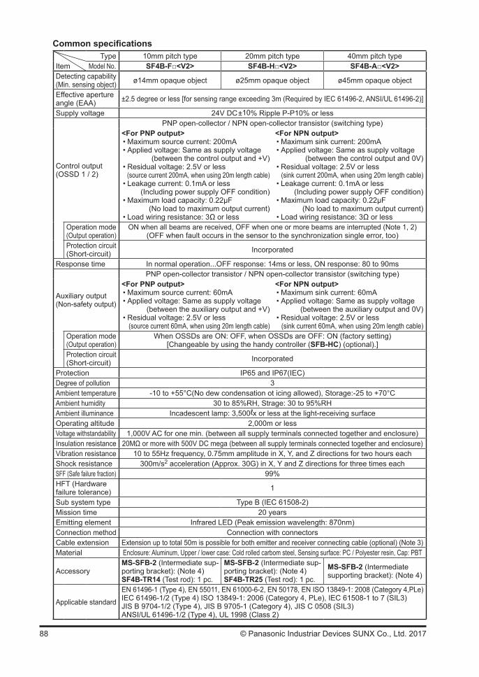
88 © Panasonic Industriar Devices SUNX Co., Ltd. 2017
Common specificationsType 10mm pitch type 20mm pitch type 40mm pitch type
Item Model No. SF4B-F<V2> SF4B-H<V2> SF4B-A<V2>Detecting capability(Min. sensing object) ø14mm opaque object ø25mm opaque object ø45mm opaque object
Effective aperture angle (EAA) ±2.5 degree or less [for sensing range exceeding 3m (Required by IEC 61496-2, ANSI/UL 61496-2)]
Supply voltage 24V DC±10% Ripple P-P10% or less
Control output(OSSD 1 / 2)
PNP open-collector / NPN open-collector transistor (switching type)<For PNP output>• Maximum source current: 200mA• Applied voltage: Same as supply voltage
(between the control output and +V)• Residual voltage: 2.5V or less
(source current 200mA, when using 20m length cable)• Leakage current: 0.1mA or less
(Including power supply OFF condition)• Maximum load capacity: 0.22µF
(No load to maximum output current)• Load wiring resistance: 3Ω or less
<For NPN output>• Maximum sink current: 200mA• Applied voltage: Same as supply voltage
(between the control output and 0V)• Residual voltage: 2.5V or less
(sink current 200mA, when using 20m length cable)• Leakage current: 0.1mA or less
(Including power supply OFF condition)• Maximum load capacity: 0.22µF
(No load to maximum output current)• Load wiring resistance: 3Ω or less
Operation mode(Output operation)
ON when all beams are received, OFF when one or more beams are interrupted (Note 1, 2)(OFF when fault occurs in the sensor to the synchronization single error, too)
Protection circuit(Short-circuit) Incorporated
Response time In normal operation...OFF response: 14ms or less, ON response: 80 to 90ms
Auxiliary output(Non-safety output)
PNP open-collector transistor / NPN open-collector transistor (switching type)<For PNP output>• Maximum source current: 60mA• Applied voltage: Same as supply voltage
(between the auxiliary output and +V)• Residual voltage: 2.5V or less
(source current 60mA, when using 20m length cable)
<For NPN output>• Maximum sink current: 60mA• Applied voltage: Same as supply voltage
(between the auxiliary output and 0V)• Residual voltage: 2.5V or less
(sink current 60mA, when using 20m length cable)Operation mode(Output operation)
When OSSDs are ON: OFF, when OSSDs are OFF: ON (factory setting)[Changeable by using the handy controller (SFB-HC) (optional).]
Protection circuit(Short-circuit) Incorporated
Protection IP65 and IP67(IEC)Degree of pollution 3Ambient temperature -10 to +55°C(No dew condensation ot icing allowed), Storage:-25 to +70°CAmbient humidity 30 to 85%RH, Strage: 30 to 95%RHAmbient illuminance Incadescent lamp: 3,500ℓx or less at the light-receiving surfaceOperating altitude 2,000m or lessVoltage withstandability 1,000V AC for one min. (between all supply terminals connected together and enclosure)Insulation resistance 20MΩ or more with 500V DC mega (between all supply terminals connected together and enclosure)Vibration resistance 10 to 55Hz frequency, 0.75mm amplitude in X, Y, and Z directions for two hours eachShock resistance 300m/s2 acceleration (Approx. 30G) in X, Y and Z directions for three times eachSFF (Safe failure fraction) 99%HFT (Hardware failure tolerance) 1
Sub system type Type B (IEC 61508-2)Mission time 20 yearsEmitting element Infrared LED (Peak emission wavelength: 870nm)Connection method Connection with connectorsCable extension Extension up to total 50m is possible for both emitter and receiver connecting cable (optional) (Note 3)Material Enclosure: Aluminum, Upper / lower case: Cold rolled carbom steel, Sensing surface: PC / Polyester resin, Cap: PBT
AccessoryMS-SFB-2 (Intermediate sup-porting bracket): (Note 4)SF4B-TR14 (Test rod): 1 pc.
MS-SFB-2 (Intermediate sup-porting bracket): (Note 4)SF4B-TR25 (Test rod): 1 pc.
MS-SFB-2 (Intermediate supporting bracket): (Note 4)
Applicable standard
EN 61496-1 (Type 4), EN 55011, EN 61000-6-2, EN 50178, EN ISO 13849-1: 2008 (Category 4,PLe)IEC 61496-1/2 (Type 4) ISO 13849-1: 2006 (Category 4, PLe), IEC 61508-1 to 7 (SIL3)JIS B 9704-1/2 (Type 4), JIS B 9705-1 (Category 4), JIS C 0508 (SIL3)ANSI/UL 61496-1/2 (Type 4), UL 1998 (Class 2)
89© Panasonic Industriar Devices SUNX Co., Ltd. 2017
Notes: 1) The beam channel is not turned OFF during muting even if it is blocked. 2) In case the blanking function is valid, the operation mode is changed. 3) The cable can be extended within 30m (for emitter / receiver) when two devices are connected in
series connection, within 20m when three devices are connected in series connection. Furthermore, when the muting lamp is used, the cable can be extended within 40m (for emitter / receiver).
4) The intermediate supporting bracket (MS-SFB-2) is enclosed with the following devices. The quantity of the enclosed bracket differs depending on the device as follows:
1 set: SF4B-F<V2>…79 to 111 beam channels SF4B-H<V2>…40 to 56 beam channels SF4B-A<V2>…20 to 28 beam channels 2 sets: SF4B-F127<V2>, SF4B-H<V2>…64 to 80 beam channels SF4B-A<V2>…32 to 40 beam channels 3 sets: SF4B-H<V2>…88 to 96 beam channels SF4B-A<V2>…44 to 48 beam channels
This device enables to set each function by using the handy controller (SFB-HC) (optional). Among the functions, the contents related to the safety distance such as the size of the minimum sensing object are varied depending on the setting condition. When setting each function, re-calculate the safety distance, and make enough space larger than the calculated safety distance. Failure to do so might cause the accident that the device cannot stop quickly before reaching the dan-gerous area of the device, resulting in the death or serious injury.
Refer to “3-9 Functions Using Handy Controller (SFB-HC) (Optional)” for details related to the function setting, or to the instruction manual attached to handy.
Both emitter and receiver are adjusted before shipment, please apply both emitter and receiver with the same serial No. The serial No. is indicated on the plates of both emitter and receiver. (Under the model represents the serial No.)
<Reference>
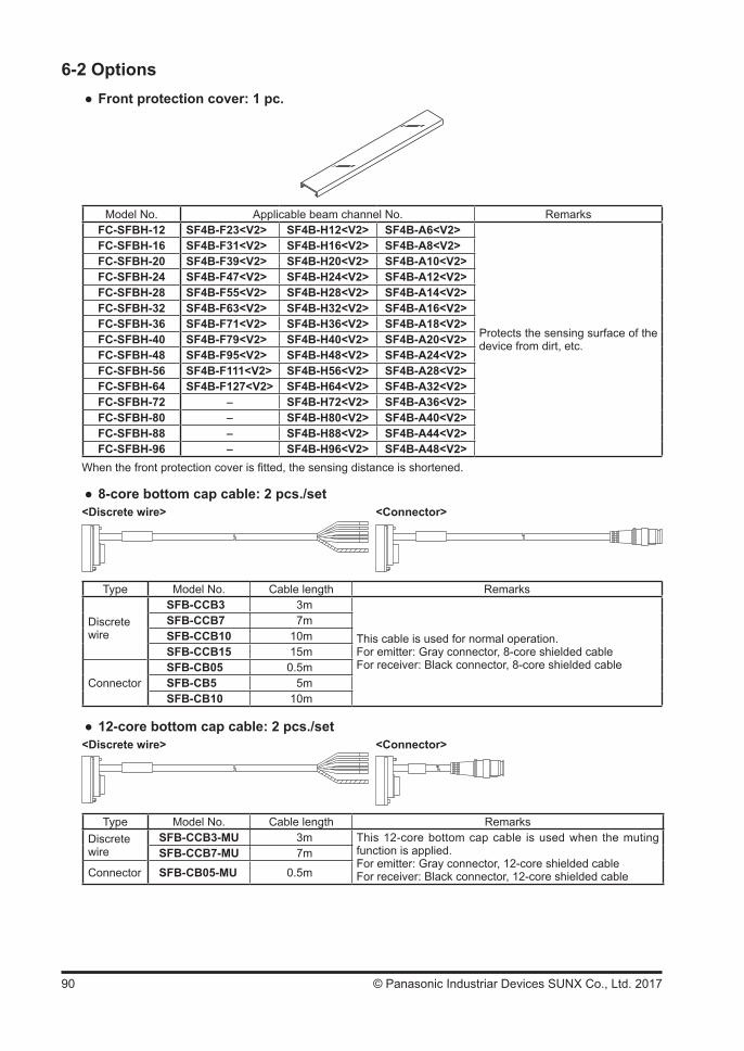
90 © Panasonic Industriar Devices SUNX Co., Ltd. 2017
6-2 Options Front protection cover: 1 pc.
Model No. Applicable beam channel No. RemarksFC-SFBH-12 SF4B-F23<V2> SF4B-H12<V2> SF4B-A6<V2>
Protects the sensing surface of the device from dirt, etc.
FC-SFBH-16 SF4B-F31<V2> SF4B-H16<V2> SF4B-A8<V2>FC-SFBH-20 SF4B-F39<V2> SF4B-H20<V2> SF4B-A10<V2>FC-SFBH-24 SF4B-F47<V2> SF4B-H24<V2> SF4B-A12<V2>FC-SFBH-28 SF4B-F55<V2> SF4B-H28<V2> SF4B-A14<V2>FC-SFBH-32 SF4B-F63<V2> SF4B-H32<V2> SF4B-A16<V2>FC-SFBH-36 SF4B-F71<V2> SF4B-H36<V2> SF4B-A18<V2>FC-SFBH-40 SF4B-F79<V2> SF4B-H40<V2> SF4B-A20<V2>FC-SFBH-48 SF4B-F95<V2> SF4B-H48<V2> SF4B-A24<V2>FC-SFBH-56 SF4B-F111<V2> SF4B-H56<V2> SF4B-A28<V2>FC-SFBH-64 SF4B-F127<V2> SF4B-H64<V2> SF4B-A32<V2>FC-SFBH-72 - SF4B-H72<V2> SF4B-A36<V2>FC-SFBH-80 - SF4B-H80<V2> SF4B-A40<V2>FC-SFBH-88 - SF4B-H88<V2> SF4B-A44<V2>FC-SFBH-96 - SF4B-H96<V2> SF4B-A48<V2>
When the front protection cover is fitted, the sensing distance is shortened.
8-core bottom cap cable: 2 pcs./set<Discrete wire> <Connector>
Type Model No. Cable length Remarks
Discrete wire
SFB-CCB3 3m
This cable is used for normal operation.For emitter: Gray connector, 8-core shielded cableFor receiver: Black connector, 8-core shielded cable
SFB-CCB7 7mSFB-CCB10 10mSFB-CCB15 15m
ConnectorSFB-CB05 0.5mSFB-CB5 5mSFB-CB10 10m
12-core bottom cap cable: 2 pcs./set<Discrete wire> <Connector>
Type Model No. Cable length RemarksDiscrete wire
SFB-CCB3-MU 3m This 12-core bottom cap cable is used when the muting function is applied.For emitter: Gray connector, 12-core shielded cableFor receiver: Black connector, 12-core shielded cable
SFB-CCB7-MU 7m
Connector SFB-CB05-MU 0.5m
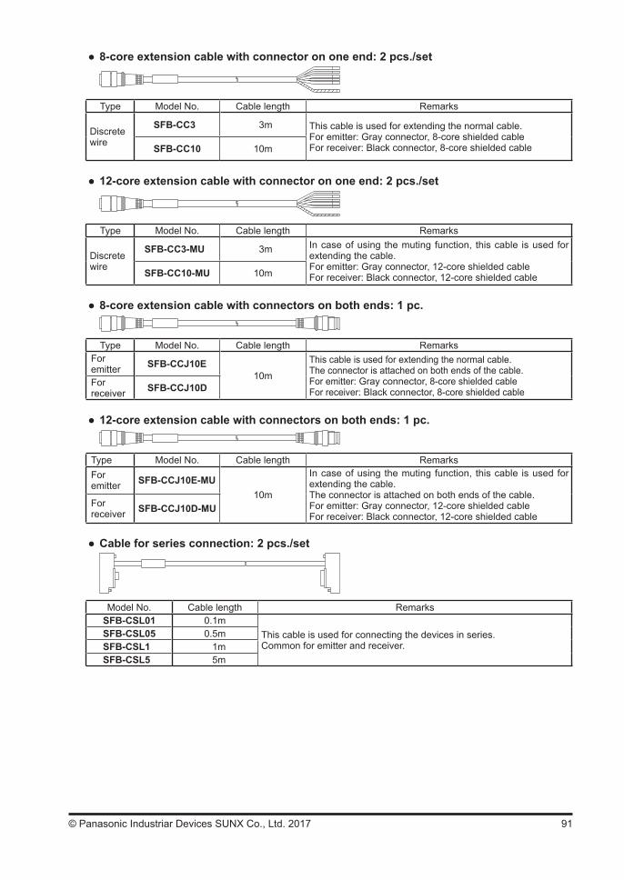
91© Panasonic Industriar Devices SUNX Co., Ltd. 2017
8-core extension cable with connector on one end: 2 pcs./set
Type Model No. Cable length Remarks
Discrete wire
SFB-CC3 3m This cable is used for extending the normal cable.For emitter: Gray connector, 8-core shielded cableFor receiver: Black connector, 8-core shielded cableSFB-CC10 10m
12-core extension cable with connector on one end: 2 pcs./set
Type Model No. Cable length Remarks
Discrete wire
SFB-CC3-MU 3m In case of using the muting function, this cable is used for extending the cable.For emitter: Gray connector, 12-core shielded cableFor receiver: Black connector, 12-core shielded cableSFB-CC10-MU 10m
8-core extension cable with connectors on both ends: 1 pc.
Type Model No. Cable length RemarksForemitter SFB-CCJ10E
10m
This cable is used for extending the normal cable. The connector is attached on both ends of the cable.For emitter: Gray connector, 8-core shielded cableFor receiver: Black connector, 8-core shielded cable
Forreceiver SFB-CCJ10D
12-core extension cable with connectors on both ends: 1 pc.
Type Model No. Cable length RemarksForemitter SFB-CCJ10E-MU
10m
In case of using the muting function, this cable is used for extending the cable.The connector is attached on both ends of the cable.For emitter: Gray connector, 12-core shielded cableFor receiver: Black connector, 12-core shielded cable
Forreceiver SFB-CCJ10D-MU
Cable for series connection: 2 pcs./set
Model No. Cable length RemarksSFB-CSL01 0.1m
This cable is used for connecting the devices in series.Common for emitter and receiver.
SFB-CSL05 0.5mSFB-CSL1 1mSFB-CSL5 5m

92 © Panasonic Industriar Devices SUNX Co., Ltd. 2017
Connecting cable exclusive for the application expansion unit SF-C14EX: 2 pcs./set
Type Model No. Cable length Remarks
Connector
SFB-CB05-EX 0.5m This cable is used for connecting the device to the applica-tion expansion unit SF-C14EX (optional).For emitter: Gray connector, 8-core shielded cableFor receiver: Black connector, 8-core shielded cable
SFB-CB5-EX 5m
SFB-CB10-EX 10m
Compatible cable: 2 pcs./set
Type Model No. Cable length Remarks
Connector
SFB-CB05-A-P
0.5m
This cable is compatible with, PNP output of SF4-AH series.SFB-CB05-A-N This cable is compatible with, NPN output of SF4-AH series.SFB-CB05-B-P This cable is compatible with, PNP output of SF2-EH series.SFB-CB05-B-N This cable is compatible with, NPN output of SF2-EH series.
M8 side mounting bracket: 4 pcs./set[L type: 2 pcs., R type: 2pcs.]
Model No. Remarks
MS-SFB-8-TThis mounting bracket allows the device to be mounted at the side.For one hexagon-socket head bolt [M8].
M8 rear mounting bracket: 4 pcs./set
Model No. Remarks
MS-SFB-7-TThis mounting bracket allows the device to be mounted at the rear.For one hexagon-socket head bolt [M8].
M8 rear / side mounting bracket set: 1 set[For rear mounting: 4 pcs., for side mounting: 4 pcs. (L type: 2 pcs., R type: 2pcs.)]
<For rear mounting> <For side mounting><L type> <R type>
Model No. Remarks
MS-SFB-1-T2This mounting bracket allows the device to be mounted at the rear or the side by changing the parts. For one hexagon-socket head bolt [M8].
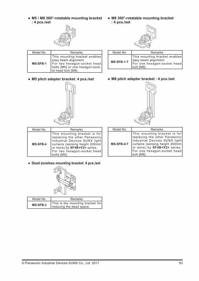
93© Panasonic Industriar Devices SUNX Co., Ltd. 2017
M8 360°-rotatable mounting bracket: 4 pcs./set
Model No. Remarks
MS-SFB-1-TThis mounting bracket enables easy beam alignment.For one hexagon-socket head bolt [M8].
M8 pitch adapter bracket : 4 pcs./set
Model No. Remarks
MS-SFB-4-T
This mount ing bracket i s fo r replacing the other Panasonic Industr ial Devices SUNX l ight curtains (sensing height 200mm or more) by SF4B<V2> series. For one hexagon-socket head bolt [M8].
M5 / M8 360°-rotatable mounting bracket: 4 pcs./set
Model No. Remarks
MS-SFB-1
This mounting bracket enables easy beam alignment.For two hexagon-socket head bolts [M5] or one hexagon-sock-et head bolt [M8].
M5 pitch adapter bracket: 4 pcs./set
Model No. Remarks
MS-SFB-4
This mount ing bracket is fo r replacing the other Panasonic Industr ial Devices SUNX l ight curtains (sensing height 200mm or more) by SF4B<V2> series.For two hexagon-socket head bolts [M5].
Dead zoneless mounting bracket: 4 pcs./set
Model No. Remarks
MS-SFB-3 This is the mounting bracket for reducing the dead space.

94 © Panasonic Industriar Devices SUNX Co., Ltd. 2017
Laser alignment tool for light curtain: 1 pc.
Model No. Remarks
SF-LAT-2N Convenient for aligning the beam channels.
Solid type control unit: 1 pc.
Model No. Remarks
SF-C12This is the control unit conform-ing to European / North American safety standards (IP65). Applicable to 12-core cable with connector.
Application expansion unit: 1 pc.
Model No. Remarks
SF-C14EXThis is the controller conforming to European / North American safety standards.The muting control function and the emergency stop input etc., are incorporated, which expand the applications of the light curtain.
SF-C14EX-01(Note)
Note: SF-C14EX-01 cannot be used in combination with the handy controller (SFB-HC) (optional).
Handy controller: 1 pc.
Model No. Remarks
SFB-HC Handy control ler that enables setting each function.
Connector connection type control unit: 1 pc.
Model No. Remarks
SF-C11This is the control unit conform-ing to European / North Ameri-can safety standards. Applicable to 8-core cable with connector.
Thin type control unit: 1 pc.
Model No. Remarks
SF-C13This is the controller conforming to European / North American safety standards.
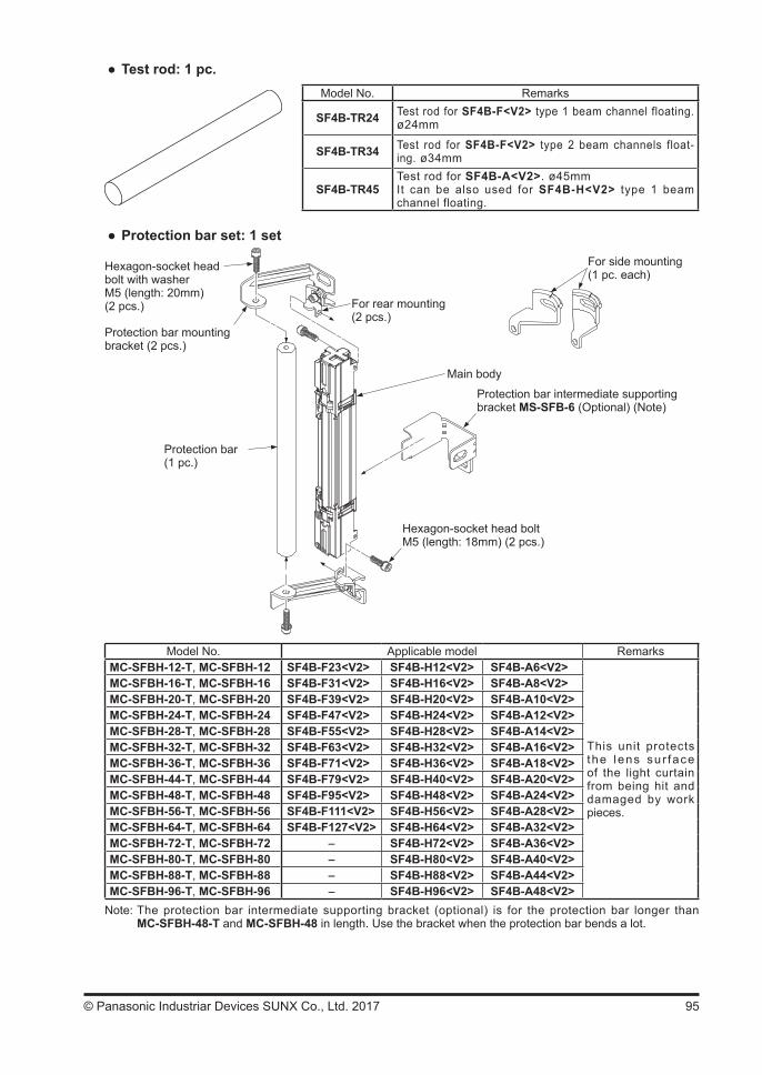
95© Panasonic Industriar Devices SUNX Co., Ltd. 2017
Test rod: 1 pc.Model No. Remarks
SF4B-TR24 Test rod for SF4B-F<V2> type 1 beam channel floating. ø24mm
SF4B-TR34 Test rod for SF4B-F<V2> type 2 beam channels float-ing. ø34mm
SF4B-TR45Test rod for SF4B-A<V2>. ø45mmIt can be also used for SF4B-H<V2> type 1 beam channel floating.
Protection bar set: 1 set
Hexagon-socket head bolt with washerM5 (length: 20mm) (2 pcs.)
Protection bar mounting bracket (2 pcs.)
Protection bar(1 pc.)
For rear mounting(2 pcs.)
Main body
Protection bar intermediate supporting bracket MS-SFB-6 (Optional) (Note)
Hexagon-socket head bolt M5 (length: 18mm) (2 pcs.)
For side mounting(1 pc. each)
Model No. Applicable model RemarksMC-SFBH-12-T, MC-SFBH-12 SF4B-F23<V2> SF4B-H12<V2> SF4B-A6<V2>
This unit protects the lens sur face of the light curtain from being hit and damaged by work pieces.
MC-SFBH-16-T, MC-SFBH-16 SF4B-F31<V2> SF4B-H16<V2> SF4B-A8<V2>MC-SFBH-20-T, MC-SFBH-20 SF4B-F39<V2> SF4B-H20<V2> SF4B-A10<V2>MC-SFBH-24-T, MC-SFBH-24 SF4B-F47<V2> SF4B-H24<V2> SF4B-A12<V2>MC-SFBH-28-T, MC-SFBH-28 SF4B-F55<V2> SF4B-H28<V2> SF4B-A14<V2>MC-SFBH-32-T, MC-SFBH-32 SF4B-F63<V2> SF4B-H32<V2> SF4B-A16<V2>MC-SFBH-36-T, MC-SFBH-36 SF4B-F71<V2> SF4B-H36<V2> SF4B-A18<V2>MC-SFBH-44-T, MC-SFBH-44 SF4B-F79<V2> SF4B-H40<V2> SF4B-A20<V2>MC-SFBH-48-T, MC-SFBH-48 SF4B-F95<V2> SF4B-H48<V2> SF4B-A24<V2>MC-SFBH-56-T, MC-SFBH-56 SF4B-F111<V2> SF4B-H56<V2> SF4B-A28<V2>MC-SFBH-64-T, MC-SFBH-64 SF4B-F127<V2> SF4B-H64<V2> SF4B-A32<V2>MC-SFBH-72-T, MC-SFBH-72 - SF4B-H72<V2> SF4B-A36<V2>MC-SFBH-80-T, MC-SFBH-80 - SF4B-H80<V2> SF4B-A40<V2>MC-SFBH-88-T, MC-SFBH-88 - SF4B-H88<V2> SF4B-A44<V2>MC-SFBH-96-T, MC-SFBH-96 - SF4B-H96<V2> SF4B-A48<V2>
Note: The protection bar intermediate supporting bracket (optional) is for the protection bar longer than MC-SFBH-48-T and MC-SFBH-48 in length. Use the bracket when the protection bar bends a lot.
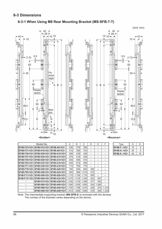
96 © Panasonic Industriar Devices SUNX Co., Ltd. 2017
6-3 Dimensions6-3-1 When Using M8 Rear Mounting Bracket (MS-SFB-7-T)
4315
F
70.5
50
E
50
D
50
2
5.5(1.5)
4228
10 10
A
G
H 10
B C
4315
F
70.5
50
E
50
D
50
2
5.5 (1.5)
4228
1010
A
10
BC
86.6 86.6
30 30
19 19
Pro-tective height
Display section
Beampitch
Displaysection
<Emitter> <Receiver>
(Unit: mm)
Model No. A B C D E F Type G HSF4B-F23<V2> SF4B-H12<V2> SF4B-A6<V2> 230 279 296 - - - SF4B-F<V2> 10 5SF4B-F31<V2> SF4B-H16<V2> SF4B-A8<V2> 310 359 376 - - - SF4B-H<V2> 20 5SF4B-F39<V2> SF4B-H20<V2> SF4B-A10<V2> 390 439 456 - - - SF4B-A<V2> 40 15SF4B-F47<V2> SF4B-H24<V2> SF4B-A12<V2> 470 519 536 - - -SF4B-F55<V2> SF4B-H28<V2> SF4B-A14<V2> 550 599 616 - - -SF4B-F63<V2> SF4B-H32<V2> SF4B-A16<V2> 630 679 696 - - -SF4B-F71<V2> SF4B-H36<V2> SF4B-A18<V2> 710 759 776 - - -SF4B-F79<V2> SF4B-H40<V2> SF4B-A20<V2> 790 839 856 395 - -SF4B-F95<V2> SF4B-H48<V2> SF4B-A24<V2> 950 999 1,016 475 - -SF4B-F111<V2> SF4B-H56<V2> SF4B-A28<V2> 1,110 1,159 1,176 555 - -SF4B-F127<V2> SF4B-H64<V2> SF4B-A32<V2> 1,270 1,319 1,336 423 847 -
- SF4B-H72<V2> SF4B-A36<V2> 1,430 1,479 1,496 477 953 -- SF4B-H80<V2> SF4B-A40<V2> 1,590 1,639 1,656 530 1,060 -- SF4B-H88<V2> SF4B-A44<V2> 1,750 1,799 1,816 438 875 1,313- SF4B-H96<V2> SF4B-A48<V2> 1,910 1,959 1,946 478 955 1,433
Note: The intermediate supporting bracket (MS-SFB-2) is enclosed with the devises. The number of the brackets varies depending on the device.
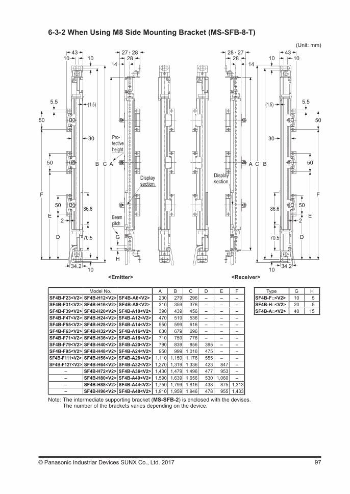
97© Panasonic Industriar Devices SUNX Co., Ltd. 2017
6-3-2 When Using M8 Side Mounting Bracket (MS-SFB-8-T)
4310
F
70.5
50
E
50
D
50
2
5.5 (1.5)
2728
1410
A
G
H
10
B C
86.6
30
34.2
<Emitter> <Receiver>
(Unit: mm)28 43
10
F
70.5
50
E
50
D
50
2
5.5(1.5)
2728
1410
A
10
BC
86.6
30
34.2
28
Pro-tective height
Display section
Beampitch
Display section
Model No. A B C D E F Type G HSF4B-F23<V2> SF4B-H12<V2> SF4B-A6<V2> 230 279 296 - - - SF4B-F<V2> 10 5SF4B-F31<V2> SF4B-H16<V2> SF4B-A8<V2> 310 359 376 - - - SF4B-H<V2> 20 5SF4B-F39<V2> SF4B-H20<V2> SF4B-A10<V2> 390 439 456 - - - SF4B-A<V2> 40 15SF4B-F47<V2> SF4B-H24<V2> SF4B-A12<V2> 470 519 536 - - -SF4B-F55<V2> SF4B-H28<V2> SF4B-A14<V2> 550 599 616 - - -SF4B-F63<V2> SF4B-H32<V2> SF4B-A16<V2> 630 679 696 - - -SF4B-F71<V2> SF4B-H36<V2> SF4B-A18<V2> 710 759 776 - - -SF4B-F79<V2> SF4B-H40<V2> SF4B-A20<V2> 790 839 856 395 - -SF4B-F95<V2> SF4B-H48<V2> SF4B-A24<V2> 950 999 1,016 475 - -SF4B-F111<V2> SF4B-H56<V2> SF4B-A28<V2> 1,110 1,159 1,176 555 - -SF4B-F127<V2> SF4B-H64<V2> SF4B-A32<V2> 1,270 1,319 1,336 423 847 -
- SF4B-H72<V2> SF4B-A36<V2> 1,430 1,479 1,496 477 953 -- SF4B-H80<V2> SF4B-A40<V2> 1,590 1,639 1,656 530 1,060 -- SF4B-H88<V2> SF4B-A44<V2> 1,750 1,799 1,816 438 875 1,313- SF4B-H96<V2> SF4B-A48<V2> 1,910 1,959 1,946 478 955 1,433
Note: The intermediate supporting bracket (MS-SFB-2) is enclosed with the devises. The number of the brackets varies depending on the device.

98 © Panasonic Industriar Devices SUNX Co., Ltd. 2017
6-3-3 Rear Mounting with Dead Zoneless Mounting Bracket (MS-SFB-3)
4334
N
70.5
50
M
50
L
50
5.5(1.5)
42
2528
15
A
G
H
14.5
K J
86.6
5.5
<Emitter> <Receiver>
(Unit: mm)50
3
3
2621
1938
4334
N
70.5
50
M
50
L
50
(1.5)
42
2528
15
A
219
14.5
KJ
86.6
5.5
50
3
3
2621
1938
5.5
Pro-tective height
Display section
Beampitch
Display section
Model No. A J K L M N Type G HSF4B-F23<V2> SF4B-H12<V2> SF4B-A6<V2> 230 209 201 - - - SF4B-F<V2> 10 5SF4B-F31<V2> SF4B-H16<V2> SF4B-A8<V2> 310 289 281 - - - SF4B-H<V2> 20 5SF4B-F39<V2> SF4B-H20<V2> SF4B-A10<V2> 390 369 361 - - - SF4B-A<V2> 40 15SF4B-F47<V2> SF4B-H24<V2> SF4B-A12<V2> 470 449 441 - - -SF4B-F55<V2> SF4B-H28<V2> SF4B-A14<V2> 550 529 521 - - -SF4B-F63<V2> SF4B-H32<V2> SF4B-A16<V2> 630 609 601 - - -SF4B-F71<V2> SF4B-H36<V2> SF4B-A18<V2> 710 689 681 - - -SF4B-F79<V2> SF4B-H40<V2> SF4B-A20<V2> 790 769 761 370 - -SF4B-F95<V2> SF4B-H48<V2> SF4B-A24<V2> 950 929 921 450 - -SF4B-F111<V2> SF4B-H56<V2> SF4B-A28<V2> 1,110 1,089 1,081 530 - -SF4B-F127<V2> SF4B-H64<V2> SF4B-A32<V2> 1,270 1,249 1,241 398 822 -
- SF4B-H72<V2> SF4B-A36<V2> 1,430 1,409 1,401 452 928 -- SF4B-H80<V2> SF4B-A40<V2> 1,590 1,569 1,561 505 1,035 -- SF4B-H88<V2> SF4B-A44<V2> 1,750 1,729 1,721 413 850 1,288- SF4B-H96<V2> SF4B-A48<V2> 1,910 1,889 1,881 453 930 1,408
Note: The intermediate supporting bracket (MS-SFB-2) is enclosed with the devises. The number of the brackets varies depending on the device.
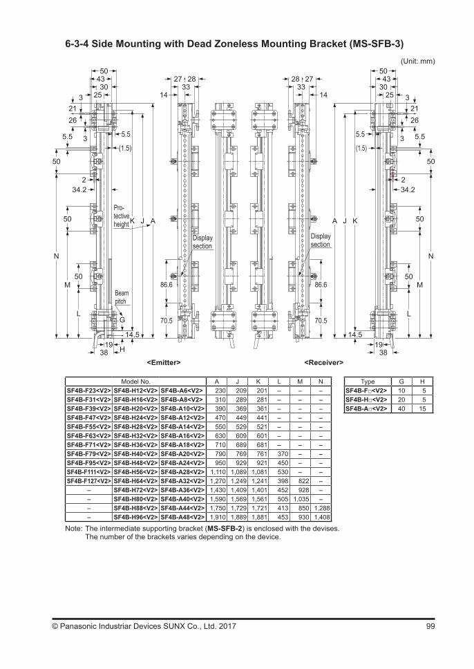
99© Panasonic Industriar Devices SUNX Co., Ltd. 2017
6-3-4 Side Mounting with Dead Zoneless Mounting Bracket (MS-SFB-3)
N
70.5
50
M
50
L
50
5.5(1.5)
27
1433
A
G
H
14.5
K J
86.6
5.5
<Emitter> <Receiver>
(Unit: mm)
3
3
2621
43
2530
50
1938
28
N
70.5
50
M
50
L
50
5.5(1.5)
27
1433
A
14.5
KJ
86.6
5.5 3
3
2621
43
2530
50
1938
28
234.2
234.2
Pro-tective height
Display section
Beampitch
Display section
Model No. A J K L M N Type G HSF4B-F23<V2> SF4B-H12<V2> SF4B-A6<V2> 230 209 201 - - - SF4B-F<V2> 10 5SF4B-F31<V2> SF4B-H16<V2> SF4B-A8<V2> 310 289 281 - - - SF4B-H<V2> 20 5SF4B-F39<V2> SF4B-H20<V2> SF4B-A10<V2> 390 369 361 - - - SF4B-A<V2> 40 15SF4B-F47<V2> SF4B-H24<V2> SF4B-A12<V2> 470 449 441 - - -SF4B-F55<V2> SF4B-H28<V2> SF4B-A14<V2> 550 529 521 - - -SF4B-F63<V2> SF4B-H32<V2> SF4B-A16<V2> 630 609 601 - - -SF4B-F71<V2> SF4B-H36<V2> SF4B-A18<V2> 710 689 681 - - -SF4B-F79<V2> SF4B-H40<V2> SF4B-A20<V2> 790 769 761 370 - -SF4B-F95<V2> SF4B-H48<V2> SF4B-A24<V2> 950 929 921 450 - -SF4B-F111<V2> SF4B-H56<V2> SF4B-A28<V2> 1,110 1,089 1,081 530 - -SF4B-F127<V2> SF4B-H64<V2> SF4B-A32<V2> 1,270 1,249 1,241 398 822 -
- SF4B-H72<V2> SF4B-A36<V2> 1,430 1,409 1,401 452 928 -- SF4B-H80<V2> SF4B-A40<V2> 1,590 1,569 1,561 505 1,035 -- SF4B-H88<V2> SF4B-A44<V2> 1,750 1,729 1,721 413 850 1,288- SF4B-H96<V2> SF4B-A48<V2> 1,910 1,889 1,881 453 930 1,408
Note: The intermediate supporting bracket (MS-SFB-2) is enclosed with the devises. The number of the brackets varies depending on the device.
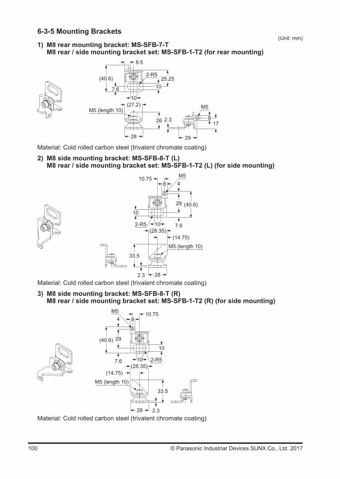
100 © Panasonic Industriar Devices SUNX Co., Ltd. 2017
6-3-5 Mounting Brackets(Unit: mm)
1) M8 rear mounting bracket: MS-SFB-7-T M8 rear / side mounting bracket set: MS-SFB-1-T2 (for rear mounting)
7.6
(40.6)
26
8.5
M5 (length 10)
10
17
29
2.3
1025.25
2-R5
(27.2)
28
M5
8
Material: Cold rolled carbon steel (trivalent chromate coating)
2) M8 side mounting bracket: MS-SFB-8-T (L) M8 rear / side mounting bracket set: MS-SFB-1-T2 (L) (for side mounting)
8
(28.35)
29
10.75
M5 (length 10)
10
4
10
2.3
M5
33.5
7.6
(40.6)
2-R5
(14.75)
28Material: Cold rolled carbon steel (trivalent chromate coating)
3) M8 side mounting bracket: MS-SFB-8-T (R) M8 rear / side mounting bracket set: MS-SFB-1-T2 (R) (for side mounting)
8
(28.35)
29
10.75
M5 (length 10)
10
4
10
2.3
M5
33.5
7.6
(40.6)
2-R5
(14.75)
28Material: Cold rolled carbon steel (trivalent chromate coating)
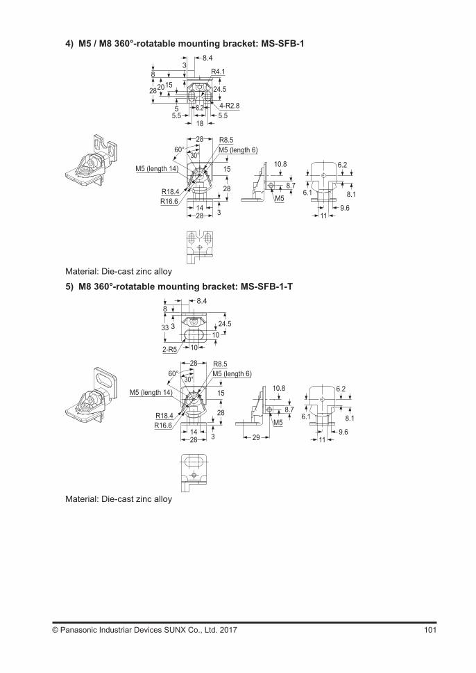
101© Panasonic Industriar Devices SUNX Co., Ltd. 2017
4) M5 / M8 360°-rotatable mounting bracket: MS-SFB-1
2028
8
8.4
4-R2.8
R4.1
15
5
3
24.5
8.25.55.5
18
2860°
30°
15
28
31428
M5 (length 6)R8.5
M5 (length 14)
R16.6R18.4
10.8
8.7
M56.1
6.2
8.1
9.611
Material: Die-cast zinc alloy
5) M8 360°-rotatable mounting bracket: MS-SFB-1-T
1033
88.4
2-R5
3 24.5
2860°
30°
15
28
31428
M5 (length 6)R8.5
M5 (length 14)
R16.6R18.4
10.8
8.7
M56.1
6.2
8.1
9.61129
10
Material: Die-cast zinc alloy
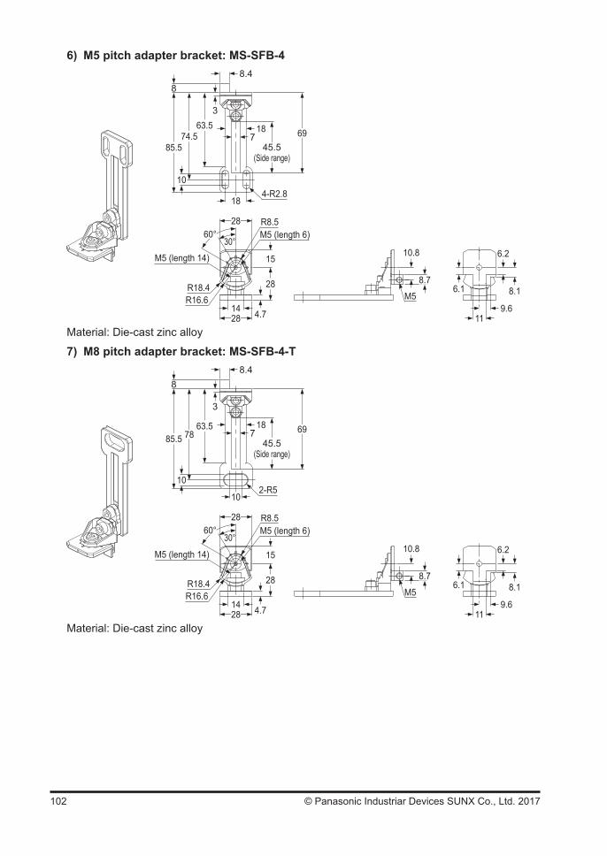
102 © Panasonic Industriar Devices SUNX Co., Ltd. 2017
6) M5 pitch adapter bracket: MS-SFB-4
88.4
4-R2.8
63.57
3
6945.5
(Side range)
18
2860°
30°
15
28
4.71428
M5 (length 6)R8.5
M5 (length 14)
R16.6R18.4
10.8
8.7
M56.1
6.2
8.1
9.611
10
74.585.5
18
Material: Die-cast zinc alloy
7) M8 pitch adapter bracket: MS-SFB-4-T
88.4
2-R5
63.57
3
6945.5
(Side range)
18
2860°
30°
15
28
4.71428
M5 (length 6)R8.5
M5 (length 14)
R16.6R18.4
10.8
8.7
M56.1
6.2
8.1
9.611
10
7885.5
10
Material: Die-cast zinc alloy

103© Panasonic Industriar Devices SUNX Co., Ltd. 2017
8) Intermediate supporting bracket / MS-SFB-2
9.5
15
30°
M4 (length 12)40
43(55)
5.8
3712
335060
5.5 5.5
32
505.5 5.5
22.213
8.32
13
8.5
2
9
(31) (28)
12.5
2
5241
10.5
14.8
24.82
8.8
4-R2.8
4-R2.8
Material: Die-cast zinc alloy
9) Dead zoneless mounting bracket / MS-SFB-3
9.5
4-R4 26
38
3951
59.568
12
59.520
28.511.6
12 2633
8.4
9.5
41.2 251915 10.8
6.8
4
26 17.3 139
4.5
5.5
5.5
5.5
5.5
8.4
50
2-R3.3 2-R4 4-R2.82-M5
2-M5
M4(length 10)
3-R1
R3
<Spacer>
ø5.5
2-R3
Material: Die-cast zinc alloy
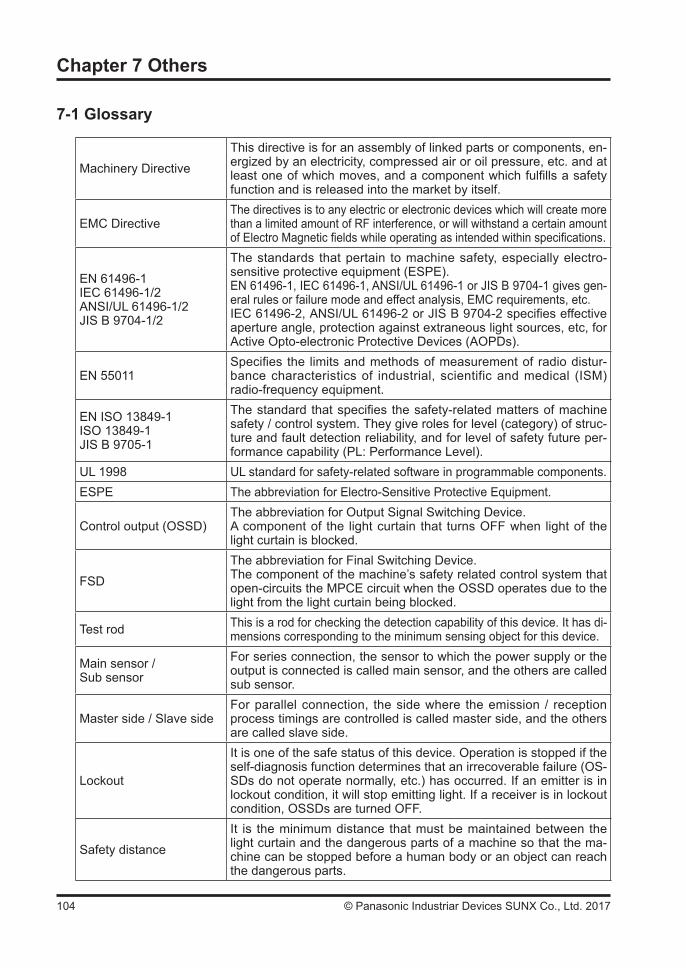
104 © Panasonic Industriar Devices SUNX Co., Ltd. 2017
Chapter 7 Others
7-1 Glossary
Machinery DirectiveThis directive is for an assembly of linked parts or components, en-ergized by an electricity, compressed air or oil pressure, etc. and at least one of which moves, and a component which fulfills a safety function and is released into the market by itself.
EMC DirectiveThe directives is to any electric or electronic devices which will create more than a limited amount of RF interference, or will withstand a certain amount of Electro Magnetic fields while operating as intended within specifications.
EN 61496-1IEC 61496-1/2ANSI/UL 61496-1/2JIS B 9704-1/2
The standards that pertain to machine safety, especially electro-sensitive protective equipment (ESPE).EN 61496-1, IEC 61496-1, ANSI/UL 61496-1 or JIS B 9704-1 gives gen-eral rules or failure mode and effect analysis, EMC requirements, etc.IEC 61496-2, ANSI/UL 61496-2 or JIS B 9704-2 specifies effective aperture angle, protection against extraneous light sources, etc, for Active Opto-electronic Protective Devices (AOPDs).
EN 55011Specifies the limits and methods of measurement of radio distur-bance characteristics of industrial, scientific and medical (ISM) radio-frequency equipment.
EN ISO 13849-1ISO 13849-1JIS B 9705-1
The standard that specifies the safety-related matters of machine safety / control system. They give roles for level (category) of struc-ture and fault detection reliability, and for level of safety future per-formance capability (PL: Performance Level).
UL 1998 UL standard for safety-related software in programmable components.ESPE The abbreviation for Electro-Sensitive Protective Equipment.
Control output (OSSD)The abbreviation for Output Signal Switching Device.A component of the light curtain that turns OFF when light of the light curtain is blocked.
FSDThe abbreviation for Final Switching Device.The component of the machine’s safety related control system that open-circuits the MPCE circuit when the OSSD operates due to the light from the light curtain being blocked.
Test rod This is a rod for checking the detection capability of this device. It has di-mensions corresponding to the minimum sensing object for this device.
Main sensor / Sub sensor
For series connection, the sensor to which the power supply or the output is connected is called main sensor, and the others are called sub sensor.
Master side / Slave sideFor parallel connection, the side where the emission / reception process timings are controlled is called master side, and the others are called slave side.
Lockout
It is one of the safe status of this device. Operation is stopped if the self-diagnosis function determines that an irrecoverable failure (OS-SDs do not operate normally, etc.) has occurred. If an emitter is in lockout condition, it will stop emitting light. If a receiver is in lockout condition, OSSDs are turned OFF.
Safety distanceIt is the minimum distance that must be maintained between the light curtain and the dangerous parts of a machine so that the ma-chine can be stopped before a human body or an object can reach the dangerous parts.
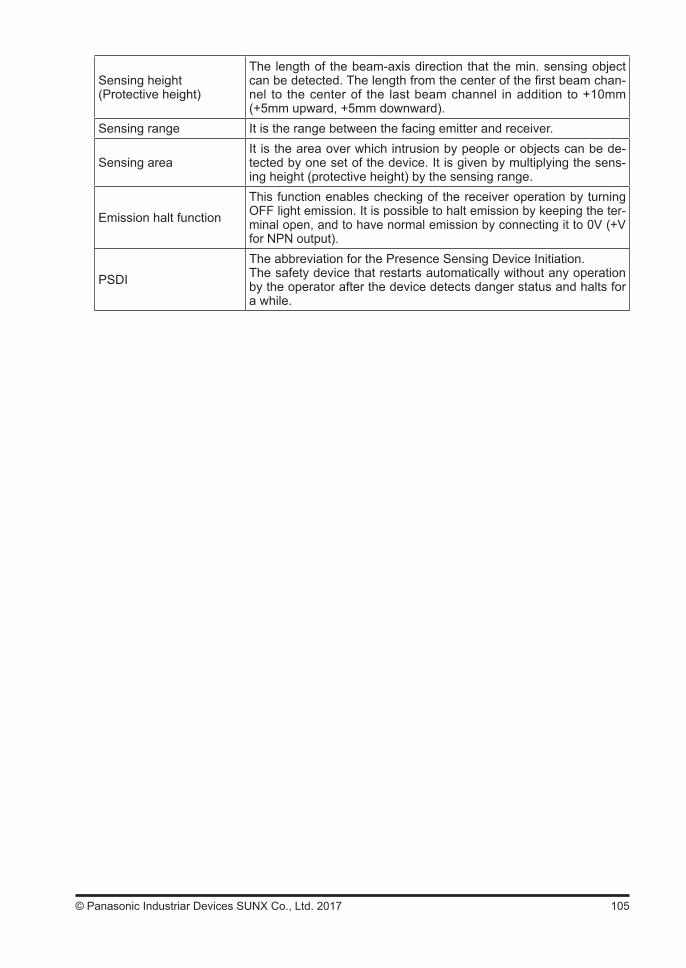
105© Panasonic Industriar Devices SUNX Co., Ltd. 2017
Sensing height(Protective height)
The length of the beam-axis direction that the min. sensing object can be detected. The length from the center of the first beam chan-nel to the center of the last beam channel in addition to +10mm (+5mm upward, +5mm downward).
Sensing range It is the range between the facing emitter and receiver.
Sensing areaIt is the area over which intrusion by people or objects can be de-tected by one set of the device. It is given by multiplying the sens-ing height (protective height) by the sensing range.
Emission halt functionThis function enables checking of the receiver operation by turning OFF light emission. It is possible to halt emission by keeping the ter-minal open, and to have normal emission by connecting it to 0V (+V for NPN output).
PSDIThe abbreviation for the Presence Sensing Device Initiation.The safety device that restarts automatically without any operation by the operator after the device detects danger status and halts for a while.
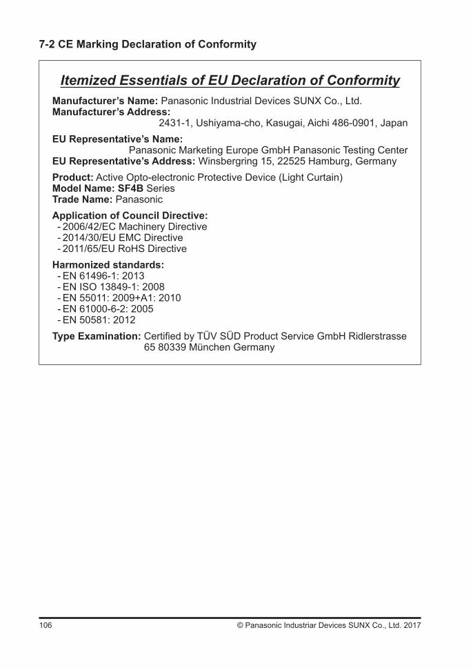
106 © Panasonic Industriar Devices SUNX Co., Ltd. 2017
7-2 CE Marking Declaration of Conformity
Itemized Essentials of EU Declaration of ConformityManufacturer’s Name: Panasonic Industrial Devices SUNX Co., Ltd.Manufacturer’s Address:
2431-1, Ushiyama-cho, Kasugai, Aichi 486-0901, JapanEU Representative’s Name:
Panasonic Marketing Europe GmbH Panasonic Testing CenterEU Representative’s Address: Winsbergring 15, 22525 Hamburg, GermanyProduct: Active Opto-electronic Protective Device (Light Curtain)Model Name: SF4B SeriesTrade Name: PanasonicApplication of Council Directive:
- 2006/42/EC Machinery Directive - 2014/30/EU EMC Directive - 2011/65/EU RoHS Directive
Harmonized standards: - EN 61496-1: 2013 - EN ISO 13849-1: 2008 - EN 55011: 2009+A1: 2010 - EN 61000-6-2: 2005 - EN 50581: 2012
Type Examination: Certified by TÜV SÜD Product Service GmbH Ridlerstrasse65 80339 München Germany
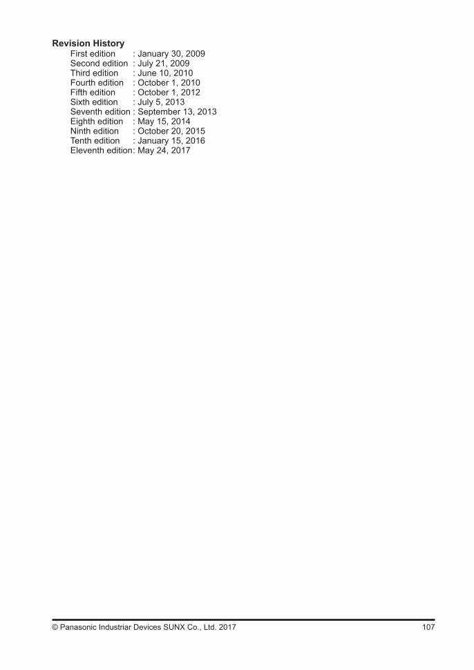
107© Panasonic Industriar Devices SUNX Co., Ltd. 2017
Revision HistoryFirst edition : January 30, 2009Second edition : July 21, 2009Third edition : June 10, 2010Fourth edition : October 1, 2010Fifth edition : October 1, 2012Sixth edition : July 5, 2013Seventh edition : September 13, 2013Eighth edition : May 15, 2014Ninth edition : October 20, 2015Tenth edition : January 15, 2016Eleventh edition : May 24, 2017

108 © Panasonic Industriar Devices SUNX Co., Ltd. 2017
(MEMO)
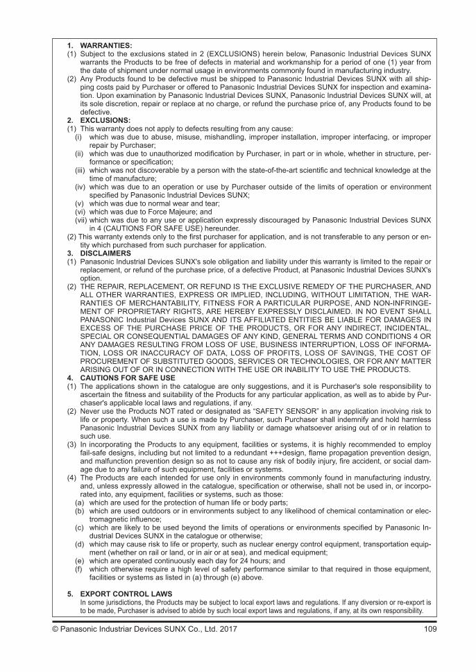
109© Panasonic Industriar Devices SUNX Co., Ltd. 2017
1. WARRANTIES:(1) Subject to the exclusions stated in 2 (EXCLUSIONS) herein below, Panasonic Industrial Devices SUNX
warrants the Products to be free of defects in material and workmanship for a period of one (1) year from the date of shipment under normal usage in environments commonly found in manufacturing industry.
(2) Any Products found to be defective must be shipped to Panasonic Industrial Devices SUNX with all ship-ping costs paid by Purchaser or offered to Panasonic Industrial Devices SUNX for inspection and examina-tion. Upon examination by Panasonic Industrial Devices SUNX, Panasonic Industrial Devices SUNX will, at its sole discretion, repair or replace at no charge, or refund the purchase price of, any Products found to be defective.
2. EXCLUSIONS:(1) This warranty does not apply to defects resulting from any cause:
(i) which was due to abuse, misuse, mishandling, improper installation, improper interfacing, or improper repair by Purchaser;
(ii) which was due to unauthorized modification by Purchaser, in part or in whole, whether in structure, per-formance or specification;
(iii) which was not discoverable by a person with the state-of-the-art scientific and technical knowledge at the time of manufacture;
(iv) which was due to an operation or use by Purchaser outside of the limits of operation or environment specified by Panasonic Industrial Devices SUNX;
(v) which was due to normal wear and tear; (vi) which was due to Force Majeure; and(vii) which was due to any use or application expressly discouraged by Panasonic Industrial Devices SUNX
in 4 (CAUTIONS FOR SAFE USE) hereunder.(2) This warranty extends only to the first purchaser for application, and is not transferable to any person or en-
tity which purchased from such purchaser for application.3. DISCLAIMERS(1) Panasonic Industrial Devices SUNX's sole obligation and liability under this warranty is limited to the repair or
replacement, or refund of the purchase price, of a defective Product, at Panasonic Industrial Devices SUNX's option.
(2) THE REPAIR, REPLACEMENT, OR REFUND IS THE EXCLUSIVE REMEDY OF THE PURCHASER, AND ALL OTHER WARRANTIES, EXPRESS OR IMPLIED, INCLUDING, WITHOUT LIMITATION, THE WAR-RANTIES OF MERCHANTABILITY, FITNESS FOR A PARTICULAR PURPOSE, AND NON-INFRINGE-MENT OF PROPRIETARY RIGHTS, ARE HEREBY EXPRESSLY DISCLAIMED. IN NO EVENT SHALL PANASONIC Industrial Devices SUNX AND ITS AFFILIATED ENTITIES BE LIABLE FOR DAMAGES IN EXCESS OF THE PURCHASE PRICE OF THE PRODUCTS, OR FOR ANY INDIRECT, INCIDENTAL, SPECIAL OR CONSEQUENTIAL DAMAGES OF ANY KIND, GENERAL TERMS AND CONDITIONS 4 OR ANY DAMAGES RESULTING FROM LOSS OF USE, BUSINESS INTERRUPTION, LOSS OF INFORMA-TION, LOSS OR INACCURACY OF DATA, LOSS OF PROFITS, LOSS OF SAVINGS, THE COST OF PROCUREMENT OF SUBSTITUTED GOODS, SERVICES OR TECHNOLOGIES, OR FOR ANY MATTER ARISING OUT OF OR IN CONNECTION WITH THE USE OR INABILITY TO USE THE PRODUCTS.
4. CAUTIONS FOR SAFE USE(1) The applications shown in the catalogue are only suggestions, and it is Purchaser's sole responsibility to
ascertain the fitness and suitability of the Products for any particular application, as well as to abide by Pur-chaser's applicable local laws and regulations, if any.
(2) Never use the Products NOT rated or designated as “SAFETY SENSOR” in any application involving risk to life or property. When such a use is made by Purchaser, such Purchaser shall indemnify and hold harmless Panasonic Industrial Devices SUNX from any liability or damage whatsoever arising out of or in relation to such use.
(3) In incorporating the Products to any equipment, facilities or systems, it is highly recommended to employ fail-safe designs, including but not limited to a redundant +++design, flame propagation prevention design, and malfunction prevention design so as not to cause any risk of bodily injury, fire accident, or social dam-age due to any failure of such equipment, facilities or systems.
(4) The Products are each intended for use only in environments commonly found in manufacturing industry, and, unless expressly allowed in the catalogue, specification or otherwise, shall not be used in, or incorpo-rated into, any equipment, facilities or systems, such as those:
(a) which are used for the protection of human life or body parts;(b) which are used outdoors or in environments subject to any likelihood of chemical contamination or elec-
tromagnetic influence;(c) which are likely to be used beyond the limits of operations or environments specified by Panasonic In-
dustrial Devices SUNX in the catalogue or otherwise;(d) which may cause risk to life or property, such as nuclear energy control equipment, transportation equip-
ment (whether on rail or land, or in air or at sea), and medical equipment;(e) which are operated continuously each day for 24 hours; and(f) which otherwise require a high level of safety performance similar to that required in those equipment,
facilities or systems as listed in (a) through (e) above.
5. EXPORT CONTROL LAWS In some jurisdictions, the Products may be subject to local export laws and regulations. If any diversion or re-export is
to be made, Purchaser is advised to abide by such local export laws and regulations, if any, at its own responsibility.

Overseas Sales Division (Head Office): 2431-1 Ushiyama-cho, Kasugai-shi, Aichi, 486-0901, Japan Telephone: +81-568-33-7861 Facsimile: +81-568-33-8591panasonic.net/id/pidsx/globalFor sales network, please visit our website.
© Panasonic Industrial Devices SUNX Co., Ltd. 2017 May 2017 PRINTED IN JAPAN WUME-SF4BV2-11
Please contact ..........