lightning surge damage to ethernet and pots ports ... · lightning surge damage to ethernet and...
TRANSCRIPT

Lightning Surge Damage
to Ethernet and POTS Ports
Connected to Inside Wiring
Joe Randolph
Randolph Telecom, Inc.

Randolph Telecom, Inc.
www.randolph-telecom.com
Mystery to Solve
How are lightning surges getting
onto inside wiring for Ethernet and
POTS ports?
Randolph Telecom, Inc.
www.randolph-telecom.com
Other Contributors From PEG
• Jim Wiese
• Mick Maytum
• Al Martin
Note:
All four of us also serve on the IEEE
PSES Telecom Advisory Committee

Randolph Telecom, Inc.
www.randolph-telecom.com
This Presentation
• Document and analyze known mechanisms
• Document and analyze new theories
• Test the new theories
• Draw some conclusions
• Offer interim design guidelines

Randolph Telecom, Inc.
www.randolph-telecom.com
Visual Damage to Ethernet Port
25
Randolph Telecom, Inc.
www.randolph-telecom.com
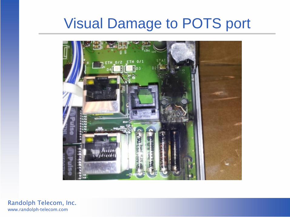
Visual Damage to POTS port

Randolph Telecom, Inc.
www.randolph-telecom.com
Who’s Looking at This Problem?
• PEG (of course!)
• IEEE PSES Telecom Advisory Committee
• ITU (K.44, K21, K.22 standards)
• Telcordia (GR-1089 NEBS standard)
• ATIS (draft Ethernet protection standard)
• USA vendor: Adtran
• Japanese vendor: NTT
Randolph Telecom, Inc.
www.randolph-telecom.com
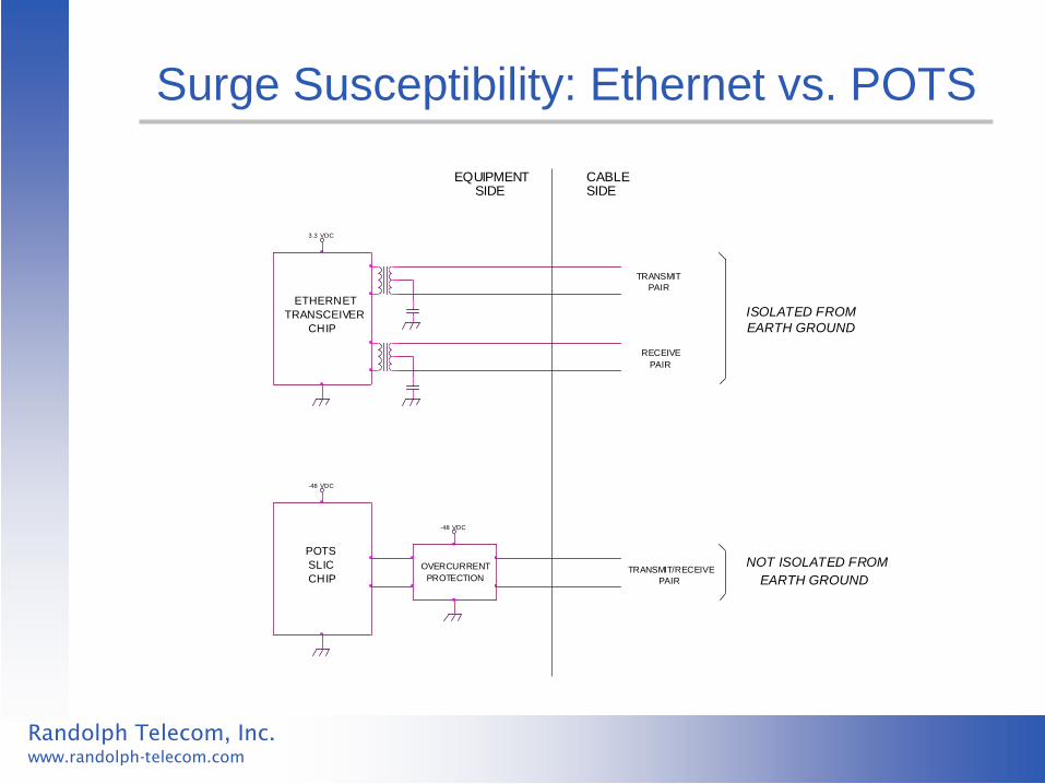
Surge Susceptibility: Ethernet vs. POTS
ISOLATED FROM
EQUIPMENT
OVERCURRENT
PROTECTION
PAIR
PAIR
TRANSMIT
NOT ISOLATED FROM
3.3 VDC
PAIR
-48 VDC
CABLE
EARTH GROUND
POTS
EARTH GROUND
CHIP
-48 VDC
CHIPTRANSMIT/RECEIVE
SIDE
RECEIVE
TRANSCEIVER
SIDE
ETHERNET
SLIC

Randolph Telecom, Inc.
www.randolph-telecom.com
Key Difference
For common mode surges:
– Ethernet ports fail when subjected to
over-voltage
– POTS ports fail when subjected to
over-current

Randolph Telecom, Inc.
www.randolph-telecom.com
Observed Failures
• Ethernet ports show evidence of
surges exceeding 2 kV
• POTS ports show evidence of surges
exceeding 100 amps (for a 2/10 uS
surge)

Randolph Telecom, Inc.
www.randolph-telecom.com
Common-Mode vs. Differential Surges

Randolph Telecom, Inc.
www.randolph-telecom.com
Common-Mode vs. Differential
• Present discussion will focus on
common mode surges
• Differential surges will be discussed
later

Randolph Telecom, Inc.
www.randolph-telecom.com
Conventional Wisdom
“Cables routed entirely within a building are inherently protected from lightning.”
Protection engineers have always known
that this is not quite true, but high energy
coupling was believed to be statistically rare.

Randolph Telecom, Inc.
www.randolph-telecom.com
Known Coupling Mechanisms
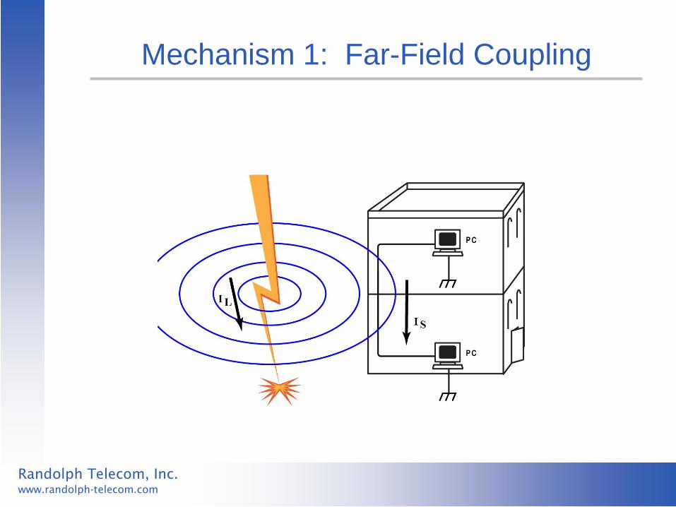
1) Far-field coupling from the actual lightning channel
2) Down-conductor coupling from direct strike to building
3) Ground potential rise (GPR)
Randolph Telecom, Inc.
www.randolph-telecom.com
Mechanism 1: Far-Field Coupling

Randolph Telecom, Inc.
www.randolph-telecom.com
Mechanism 2: Down-Conductor Coupling
Randolph Telecom, Inc.
www.randolph-telecom.com
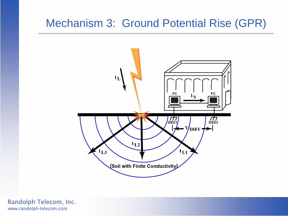
Mechanism 3: Ground Potential Rise (GPR)
Randolph Telecom, Inc.
www.randolph-telecom.com
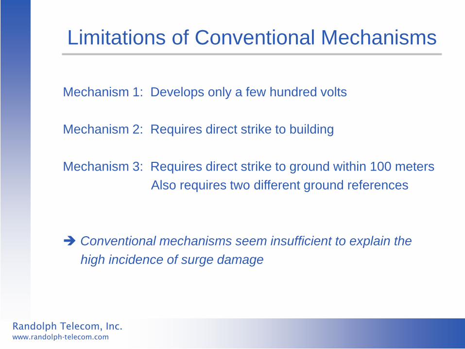
Limitations of Conventional Mechanisms
Mechanism 1: Develops only a few hundred volts
Mechanism 2: Requires direct strike to building
Mechanism 3: Requires direct strike to ground within 100 meters
Also requires two different ground references
Conventional mechanisms seem insufficient to explain the
high incidence of surge damage

Randolph Telecom, Inc.
www.randolph-telecom.com
Other Possible Coupling Mechanisms?
If we could identify the surge coupling
mechanisms, we could do a better job of
defining what we need to protect against:
• Open-circuit voltage ?
• Short-circuit current ?
• Waveform ?
• Common mode vs. differential ?

Randolph Telecom, Inc.
www.randolph-telecom.com
New Theories
Note: All three theories assume coupling of surges that originate
on the AC mains Theory 1: Catastrophic breakdown Theory 2: Capacitive coupling Theory 3: Interaction with multi-port surge protectors
Randolph Telecom, Inc.
www.randolph-telecom.com
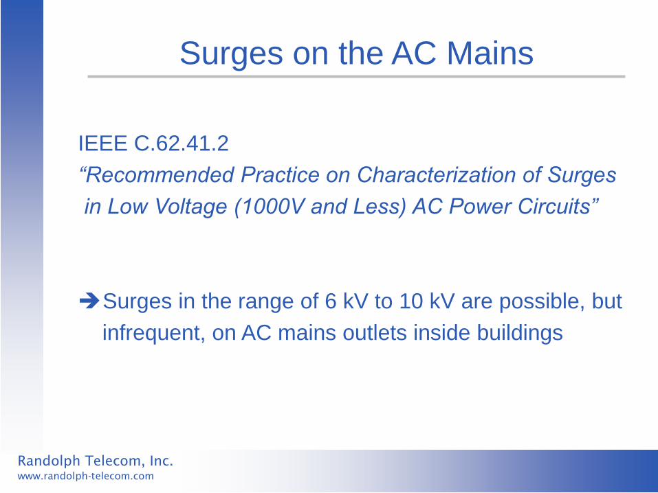
Surges on the AC Mains
IEEE C.62.41.2
“Recommended Practice on Characterization of Surges
in Low Voltage (1000V and Less) AC Power Circuits”
Surges in the range of 6 kV to 10 kV are possible, but
infrequent, on AC mains outlets inside buildings
Randolph Telecom, Inc.
www.randolph-telecom.com
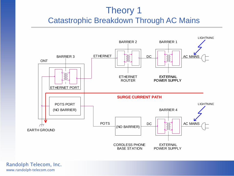
Theory 1
Catastrophic Breakdown Through AC Mains
AC MAINS
BARRIER 2
ONT
SURGE CURRENT PATH
DC
EARTH GROUND
DC(NO BARRIER)
(NO BARRIER)
ETHERNET PORT
BARRIER 4
POWER SUPPLY
POTS PORT
POWER SUPPLYEXTERNAL
LIGHTNING
EXTERNAL
EXTERNAL
POWER SUPPLY
BARRIER 3
ROUTER
BASE STATION
ETHERNET
BARRIER 1
POTS
AC MAINS
ETHERNET
LIGHTNING
CORDLESS PHONE

Randolph Telecom, Inc.
www.randolph-telecom.com
Typical AC Wall Supply
Isolation
Components

Randolph Telecom, Inc.
www.randolph-telecom.com
Typical Ethernet Port
Isolation
Components

Randolph Telecom, Inc.
www.randolph-telecom.com
Typical Ethernet Transformer

Randolph Telecom, Inc.
www.randolph-telecom.com
Measured Failure Thresholds of Ethernet Transformers
Ethernet Transformer Breakdown Notes
Wurth 7090-37 8 kV
Wurth 7090-37 7 kV
Falco LV2001 10 kV
Pulse H1164 Over 10 kV
Halo TG110-RP26NY Over 10 kV
Pulse T1144 9 kV
Pulse H1102 8 kV
Pulse H2009 10 kV
Pulse H5007NL 5 kV Second sample was 9 kV
Randolph Telecom, Inc.
www.randolph-telecom.com
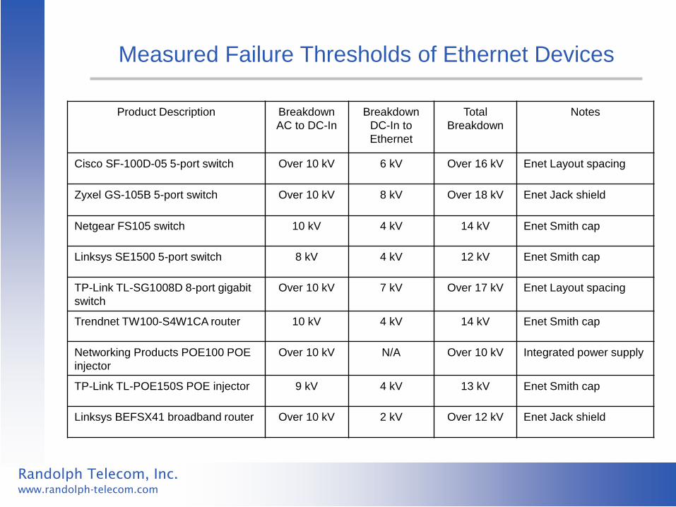
Measured Failure Thresholds of Ethernet Devices
Product Description Breakdown
AC to DC-In
Breakdown
DC-In to
Ethernet
Total
Breakdown
Notes
Cisco SF-100D-05 5-port switch Over 10 kV 6 kV Over 16 kV Enet Layout spacing
Zyxel GS-105B 5-port switch Over 10 kV 8 kV Over 18 kV Enet Jack shield
Netgear FS105 switch 10 kV 4 kV 14 kV Enet Smith cap
Linksys SE1500 5-port switch 8 kV 4 kV 12 kV Enet Smith cap
TP-Link TL-SG1008D 8-port gigabit
switch
Over 10 kV 7 kV Over 17 kV Enet Layout spacing
Trendnet TW100-S4W1CA router 10 kV 4 kV 14 kV Enet Smith cap
Networking Products POE100 POE
injector
Over 10 kV N/A Over 10 kV Integrated power supply
TP-Link TL-POE150S POE injector 9 kV 4 kV 13 kV Enet Smith cap
Linksys BEFSX41 broadband router Over 10 kV 2 kV Over 12 kV Enet Jack shield
Randolph Telecom, Inc.
www.randolph-telecom.com
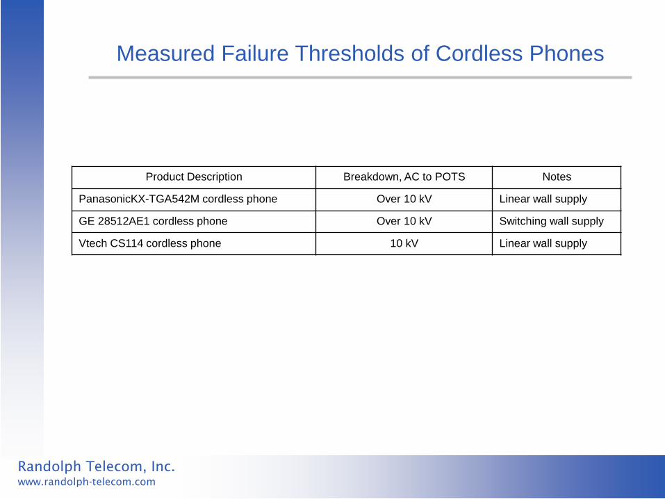
Measured Failure Thresholds of Cordless Phones
Product Description Breakdown, AC to POTS Notes
PanasonicKX-TGA542M cordless phone Over 10 kV Linear wall supply
GE 28512AE1 cordless phone Over 10 kV Switching wall supply
Vtech CS114 cordless phone 10 kV Linear wall supply
Randolph Telecom, Inc.
www.randolph-telecom.com
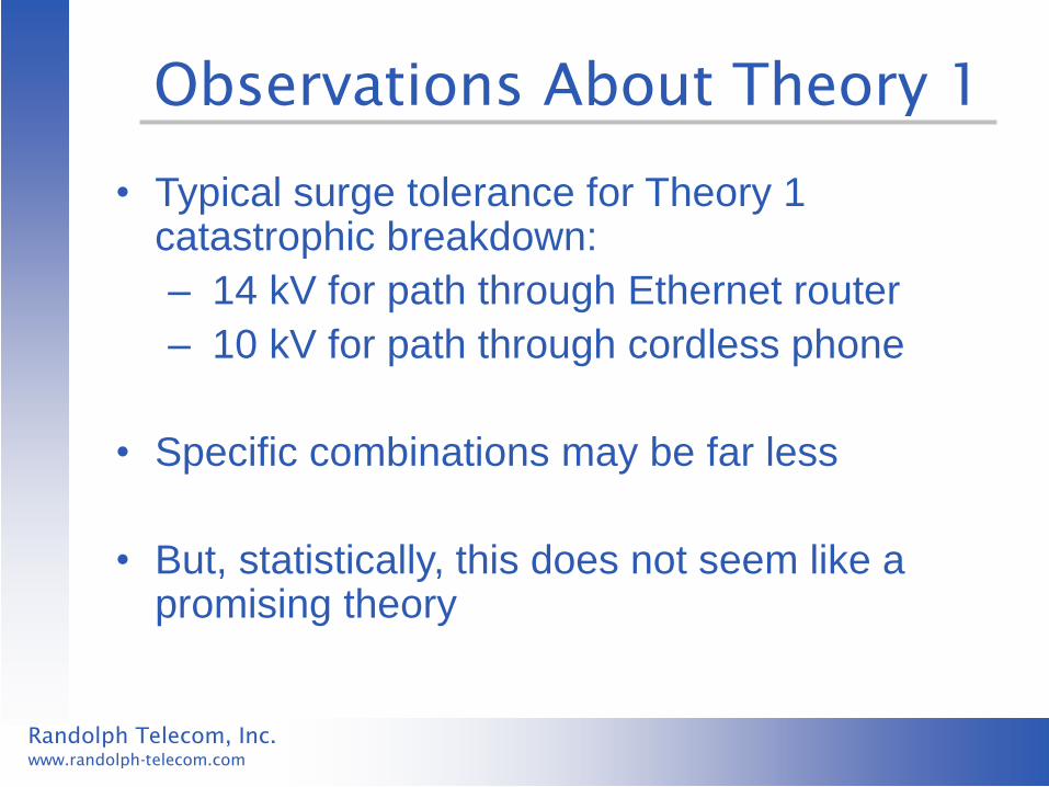
Observations About Theory 1
• Typical surge tolerance for Theory 1 catastrophic breakdown:
– 14 kV for path through Ethernet router
– 10 kV for path through cordless phone
• Specific combinations may be far less
• But, statistically, this does not seem like a promising theory
Randolph Telecom, Inc.
www.randolph-telecom.com
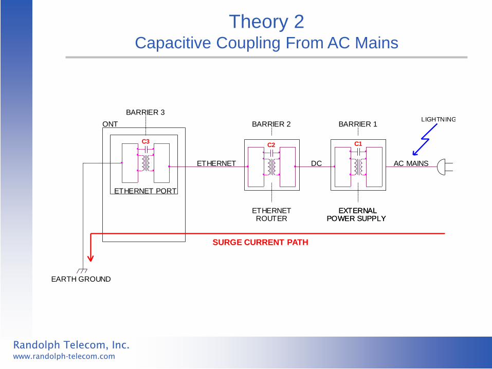
Theory 2 Capacitive Coupling From AC Mains
POWER SUPPLY
AC MAINS
ETHERNETPOWER SUPPLY
C2
LIGHTNINGBARRIER 1ONT
EARTH GROUND
EXTERNAL
BARRIER 3
DC
C1
ROUTEREXTERNAL
SURGE CURRENT PATH
ETHERNET
C3
ETHERNET PORT
BARRIER 2

Randolph Telecom, Inc.
www.randolph-telecom.com
Circuit Model for Theory 2
1111 V
IMPULSE CURRENT PATH
ONT
ETHERNET ETHERNET
C2 C1
PORT
AC MAINS
ROUTER
(2200 pF)(1000 pF)(1000 pF)
C3
6 kV IMPULSE
POWER SUPPLY
2444 V2444 V

Randolph Telecom, Inc.
www.randolph-telecom.com
Observations About Theory 2
• Seems promising for explaining some
Ethernet failures, but still requires very high
voltages on AC mains (typically at least 8 kV)
• Can not be used to explain POTS damage
because impulse current is small

Randolph Telecom, Inc.
www.randolph-telecom.com
Theory 3
Interaction With Multi-Port Surge Protectors

Randolph Telecom, Inc.
www.randolph-telecom.com
Circuit Model For Theory 3
I-GND
DISTRIBUTION
GROUND ROD
COAX
TV
AC IN
AC IN FROM OUTSIDE
PORT
IN
POTS
70 V
TVS
P4
(SURGE PROTECTOR GROUND REFERENCE)
ROUTER
AC WALL
AC OUT
POINT APOTS ETHERNET COAX
MOV
400 VOLT
P2
ETHERNETL-GND
OUT
PANEL
POTS
P5
GAS TUBE
100 VOLT
ETHERNET
MOV
300 VOLT
P3
(ONT GROUND REFERENCE)
LIGHTNING
PHONE
OUTLET
OUT
COAX
COMBINATION SURGE PROTECTOR
POTS
IN
OPTICAL NETWORK TERMINAL (ONT)
PORT
MOV
400 VOLT
P1
OUT
V-SURGE
ETHERNET
PORT
AC
IN
Randolph Telecom, Inc.
www.randolph-telecom.com
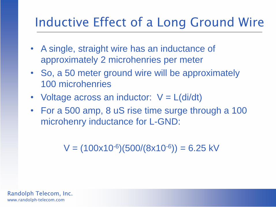
Inductive Effect of a Long Ground Wire
• A single, straight wire has an inductance of
approximately 2 microhenries per meter
• So, a 50 meter ground wire will be approximately
100 microhenries
• Voltage across an inductor: V = L(di/dt)
• For a 500 amp, 8 uS rise time surge through a 100
microhenry inductance for L-GND:
V = (100x10-6)(500/(8x10-6)) = 6.25 kV

Randolph Telecom, Inc.
www.randolph-telecom.com
Observations About Theory 3
• Valid mechanism that can generate
observed damage on both Ethernet and
POTS ports
• But, only applies when multi-port surge
protectors have been installed on equipment
connected to these ports

Randolph Telecom, Inc.
www.randolph-telecom.com
Summary of Limitations
Theory 1: Requires unusually high surge voltages on AC mains (typically more than 10 kV)
Theory 2: Looks good, but delivers only high voltage, not high current. Can not explain POTS failures. Also, requires high surge voltages on AC mains (typically more than 8 kV)
Theory 3: Looks good, delivers high voltage and high current, but only if multi-port surge protectors are installed

Randolph Telecom, Inc.
www.randolph-telecom.com
Common-Mode vs. Differential Surges
• The preceding discussion has focused on
common mode surges
• In some cases differential surges should
also be considered
Randolph Telecom, Inc.
www.randolph-telecom.com
Conventional Theory
• All surges on twisted-pair cables begin as
common-mode surges
• Only an external mechanism (such as a
surge protector) can cause a a “common-
mode-to-differential conversion”

Randolph Telecom, Inc.
www.randolph-telecom.com
Common-Mode-to-Differential Conversion
Caused by Asymmetric Triggering of External Protectors
Randolph Telecom, Inc.
www.randolph-telecom.com
Common-Mode-to-Differential Conversion
(Continued)
• Ethernet ports can be sensitive to this:
– Designed to pass high frequency differential signals
– Typically not well protected for differential surges
• POTS ports generally not sensitive to this:
– Typical POTS protection operates equally well for both
common mode and differential surges
Randolph Telecom, Inc.
www.randolph-telecom.com
Mitigating Factors for Differential Surge
Risk to Ethernet
• External Ethernet protectors are not always present
• Only certain types of external protectors will create
a common-mode-to-differential conversion
These factors limit the potential hazard, but
a conservative strategy would include
differential protection on Ethernet ports

Randolph Telecom, Inc.
www.randolph-telecom.com
Interim Guidelines
• Design POTS ports to survive a 500 amp, 2/10 uS
common mode surge
• Design Ethernet ports to survive a 6 kV, 2/10 uS
common mode surge
• Differential surge tolerance for Ethernet ports may be
desirable if external surge protectors will be used
Randolph Telecom, Inc.
www.randolph-telecom.com
Guidelines Not Difficult or Expensive
• POTS guideline is similar to commonly used standard for outside POTS lines
• Ethernet guideline requires three elements: – Improved insulation on transformer wires
– Careful attention to capacitors that bridge barrier
– Careful attention to spacings in board layout
• Ethernet Protection for differential surges requires careful selection of additional components
Randolph Telecom, Inc.
www.randolph-telecom.com
Continuing the Investigation
• Examine actual field failures to try and match their
characteristics to a particular coupling mechanism
• Evaluate designs presently in the field to compare
their failure rates and the failure mechanisms
These steps will help identify the surge
coupling mechanisms, and will help guide
development of surge requirements that
match the actual field environment