lightweight torque-vectoring transmission for the electric ... · lightweight torque-vectoring...
TRANSCRIPT

Lightweight Torque-Vectoring Transmission for theElectric Vehicle VISIO.M
Philipp GwinnerResearch Associate
Gear Research Center (FZG)Dept. of Mechanical EngineeringTechnische Universitat Munchen
Germany, Munich 85748Email: [email protected]
Michael OttoResearch Group Head
Gear Research Center (FZG)Dept. of Mechanical EngineeringTechnische Universitat Munchen
Germany, Munich 85748Email: [email protected]
Karsten StahlFull Professor
Gear Research Center (FZG)Dept. of Mechanical EngineeringTechnische Universitat Munchen
Germany, Munich 85748Email: [email protected]
Abstract—To meet the challenging requirement of high ef-ficiency for fully electric drive vehicles, lightweight designthroughout the entire vehicle architecture becomes increasinglyimportant. The high speeds of electric drives currently in use,and their low noise emission in comparison to conventionalcombustion engines require axle drives with acoustically lownoise gear concepts. In this paper a novel axle drive concept forelectric vehicles with a mechanical torque-vectoring functionalityis presented. Conventional axle drives for automotive applicationsfeature helical gears in order to ensure quiet operation of thepower train, however, risking the consequence of additionalaxial forces in comparison to ordinary cylindrical gears. Thiscauses higher loads on the shafts and housing and has to beconsidered during the design process to ensure an adequate loadcarrying capacity and low deformations of the components. Inthis paper an axle drive concept will be shown featuring no axialforces, so that the acting load on the gearbox system can bereduced explicitly. This approach permits a downsizing of thegearbox components and the application of lightweight materials.Thus, it is possible to utilize a housing made of a reinforcedplastic material as well as plastic gears into the torque-vectoringsystem to significantly reduce the transmission weight. Generally,conventional axial force free spur gear designs, e. g. cylindricalgears, do not provide a beneficial acoustical excitation level incomparison to helical gear designs. Due to a specific gear layout,which is designed for the axle drive of the VISIO.M vehicle, thearithmetical noise excitation can be reduced and makes the useof innovative lightweight materials possible. The design of thepresented lightweight transmission as well as the weight and theexcitation level will be compared to former construction stagesof the transmission.
Keywords—torque-vectoring, electric vehicle, plastic gears, ex-citation level, active differential
I. INTRODUCTION
At the Technische Universitat Munchen a network of14 research institutes and associated industrial partners aredeveloping a fully electric powered subcompact vehicle calledVISIO.M (see Fig. 1). The related research project, which is thefollow-up project of the MUTE project, started in March 2012and is targeting to build up an optimized prototype vehiclein terms of costs, enhanced safety and high efficiency. Thelow priced and innovative vehicle is designed for 2 passengersand a suburban purpose. Related to the vehicle class L7e,the net weight (without battery and payload) of the vehicle
Fig. 1. Electric vehicle VISIO.M
Research project MUTE Visio.M
Construction stage CS01 CS02 CS03
Concept 2-stage axle gear
torque-vectoring
2-stage axle gear
torque-vectoring
2-stage axle gear
torque-vectoring
Technology state of the art optimized lightweight +
optimized
Engineering Progress, Cost & Weight Reduction
Fig. 2. Transmission construction stages
is limited to 450 kg. The primary energy storage consistsof a rechargeable lithium-ion-battery with a nominal capacityof 13.5 kWh, which guarantees a range of at least 100 kmconsidering an suburban-oriented driving cycle.
The VISIO.M vehicle features a rear wheel drive dueto the safety concept, the limited vehicle package and highrequirements on driving dynamics. The power train consistsof an asynchronous drive motor with a nominal driving powerat the wheels of 15 kW (restricted by the vehicle classL7e) and a maximum speed of 12, 000 rpm at a vehiclevelocity of 120 km/h. The nominal power, which covers theload spectrum of characteristic suburban driving cycles, canbe temporarily raised to a peak power of 30 kW , i. e. foracceleration driving conditions. The axle drive provides thespeed and torque adaption of the drive motor to the wheels.
120
0
100 80 60 40 20 0
-800
-600
-400
-200
0
200
400
600
800
axle
torq
ue (N
m)
0,2
0,4
0,6
0,8
1
1,2
1,4
1,6 nominal
peak
velocity (km/h)
0
frequ.(%)
peak
nominal
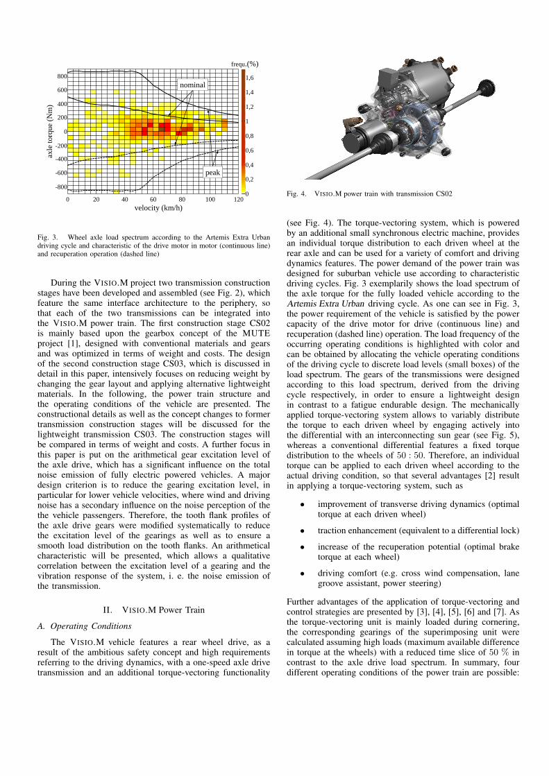
Fig. 3. Wheel axle load spectrum according to the Artemis Extra Urbandriving cycle and characteristic of the drive motor in motor (continuous line)and recuperation operation (dashed line)
During the VISIO.M project two transmission constructionstages have been developed and assembled (see Fig. 2), whichfeature the same interface architecture to the periphery, sothat each of the two transmissions can be integrated intothe VISIO.M power train. The first construction stage CS02is mainly based upon the gearbox concept of the MUTEproject [1], designed with conventional materials and gearsand was optimized in terms of weight and costs. The designof the second construction stage CS03, which is discussed indetail in this paper, intensively focuses on reducing weight bychanging the gear layout and applying alternative lightweightmaterials. In the following, the power train structure andthe operating conditions of the vehicle are presented. Theconstructional details as well as the concept changes to formertransmission construction stages will be discussed for thelightweight transmission CS03. The construction stages willbe compared in terms of weight and costs. A further focus inthis paper is put on the arithmetical gear excitation level ofthe axle drive, which has a significant influence on the totalnoise emission of fully electric powered vehicles. A majordesign criterion is to reduce the gearing excitation level, inparticular for lower vehicle velocities, where wind and drivingnoise has a secondary influence on the noise perception of thethe vehicle passengers. Therefore, the tooth flank profiles ofthe axle drive gears were modified systematically to reducethe excitation level of the gearings as well as to ensure asmooth load distribution on the tooth flanks. An arithmeticalcharacteristic will be presented, which allows a qualitativecorrelation between the excitation level of a gearing and thevibration response of the system, i. e. the noise emission ofthe transmission.
II. VISIO.M Power Train
A. Operating Conditions
The VISIO.M vehicle features a rear wheel drive, as aresult of the ambitious safety concept and high requirementsreferring to the driving dynamics, with a one-speed axle drivetransmission and an additional torque-vectoring functionality
Fig. 4. VISIO.M power train with transmission CS02
(see Fig. 4). The torque-vectoring system, which is poweredby an additional small synchronous electric machine, providesan individual torque distribution to each driven wheel at therear axle and can be used for a variety of comfort and drivingdynamics features. The power demand of the power train wasdesigned for suburban vehicle use according to characteristicdriving cycles. Fig. 3 exemplarily shows the load spectrum ofthe axle torque for the fully loaded vehicle according to theArtemis Extra Urban driving cycle. As one can see in Fig. 3,the power requirement of the vehicle is satisfied by the powercapacity of the drive motor for drive (continuous line) andrecuperation (dashed line) operation. The load frequency of theoccurring operating conditions is highlighted with color andcan be obtained by allocating the vehicle operating conditionsof the driving cycle to discrete load levels (small boxes) of theload spectrum. The gears of the transmissions were designedaccording to this load spectrum, derived from the drivingcycle respectively, in order to ensure a lightweight designin contrast to a fatigue endurable design. The mechanicallyapplied torque-vectoring system allows to variably distributethe torque to each driven wheel by engaging actively intothe differential with an interconnecting sun gear (see Fig. 5),whereas a conventional differential features a fixed torquedistribution to the wheels of 50 : 50. Therefore, an individualtorque can be applied to each driven wheel according to theactual driving condition, so that several advantages [2] resultin applying a torque-vectoring system, such as
• improvement of transverse driving dynamics (optimaltorque at each driven wheel)
• traction enhancement (equivalent to a differential lock)
• increase of the recuperation potential (optimal braketorque at each wheel)
• driving comfort (e.g. cross wind compensation, lanegroove assistant, power steering)
Further advantages of the application of torque-vectoring andcontrol strategies are presented by [3], [4], [5], [6] and [7]. Asthe torque-vectoring unit is mainly loaded during cornering,the corresponding gearings of the superimposing unit werecalculated assuming high loads (maximum available differencein torque at the wheels) with a reduced time slice of 50 % incontrast to the axle drive load spectrum. In summary, fourdifferent operating conditions of the power train are possible:

Superimposing gear Spur gear differential
Rig
ht W
heel
Lef
t Whe
el
Electric Drive MotorSuperimposing
Electric Machine
Interconnectingsun gear
Axle Drive
Fig. 5. VISIO.M power train − structure scheme
The drive motor is running in motor operation if the vehiclespeed is kept constant or during acceleration with or withoutactivated torque-vectoring (operating conditions 1 and 2). The3rd and 4th operating condition is the recuperation mode,where the drive motor is running in generator operation withor without activated torque-vectoring. The torque-vectoringelectric machine is running in generator and motor operationas well, depending on the direction of the wheels’ speed. Iftorque is transferred to the faster running wheel, the torque-vectoring motor is running in motor operation and vice versa.
B. Layout and functioning
In principle, the transmission (CS02 & CS03) of theVISIO.M vehicle consists of three different assembly groups:the axle drive, the differential and the torque-vectoring unit(see Fig. 5). The axle drive of the CS02 is designed as aconventional two-stage spur gear train with helical gears and atotal gear ratio of i = 10.15. The final drive contains a compactdesigned spur gear differential, which is mounted into the finaldrive featuring a planetary gear train of the Ravigneaux type.Further torque-vectoring transmissions are presented by [8],[9] and [10]. During straight ahead driving, the final driveas well as the differential gears rotate with the same absolutespeed. During cornering the differential gears are rotating witha relative speed in comparison to the final drive wheel toallow the different speeds of the driven vehicle wheels. Thedifferential gear ratio between the two wheel output shafts,which are the sun gear and the carrier shaft of the differential,is idiff = −1 respectively. The axle torque is distributedconventionally by 50 : 50 to the wheels, if the torque-vectoringunit is not activated. Due to the symmetrical layout of thesuperimposing unit, the superimposing electric machine standsstill if the wheel speeds of the vehicle are identical, i. e.during straight ahead driving. Thus, the power losses of thetorque-vectoring unit can be reduced. The differential torque
20
18
16
14
12
10
8
6
4
2
0 0 500 1000 1500 2000 2500 3000 3500 4000 4500
nominal
peak
speed (rpm)
torq
ue
(Nm
)
operating
range
electronic
limitation
Fig. 6. Map of the superimposing electric machine for transmission CS02(orange line) and CS03 (blue line)
ratio can be influenced or rather changed by actuating thesuperimposing electric machine of the torque-vectoring unit.Then, the interconnecting sun gear, which is engaging activelyinto the differential, is loaded and transfers torque from onedriven wheel to another. To reduce the torque requirementsof the superimposing electric machine, two identically con-structed planetary gear trains are assembled into the torque-vectoring unit to provide a high superimposing gear ratio.Thus, it is possible to provide high differences in torque atthe wheels using a small superimposing electric machine. Incontrast to the MUTE transmission CS01, where one sun gearof the superimposing planetary gear train is directly driven by ahollow shaft electric machine, the superimposing unit of CS02& CS03 features two pre-arranged cylindrical gear stages.These cylindrical gear stages are additionally implementedto the superimposing planetary gear train in order to furtherraise the superimposing gear ratio and to be able to mounta conventional and modular torque motor, which is availablein different power classes and can easily be mounted to anddismounted from the transmission. The applied torque motoris available with a different face-to-face length and nominalpower respectively.
The adjustable difference in torque at the wheels providedby the torque-vectoring unit is dependent on the gear ratioof the superimposing unit and the output torque of the super-imposing electric machine. According to [2] the difference intorque at the driven wheels ∆Twheels is defined as
∆Twheels = iTV · Tsem (1)
with the superimposing gear ratio iTV and the torque ofthe superimposing electric machine Tsem. The speed of thesuperimposing electric machine is a function of the speeddifference of the wheels and the superimposing gear ratio andreads:
nsem =iTV
2· ∆nwheels (2)

The superimposing planetary gears of the CS02 and CS03have a gear ratio of 12 and the pre-arranged cylindrical gearstages a gear ratio of 4, so that the total superimposing gearratio iTV is 48. With an electronically limited peak torqueof 12 Nm for the torque motor of the CS02 and 6.5 Nmof the CS03 (see Fig. 6), a maximum difference in torqueat the wheels ∆Twheels of 576 Nm and 312 Nm can bereached. As the superimposing electric machine is not activelycooled, the peak torque of the superimposing electric machinehas to be limited electronically to ensure the availability ofthis torque for up to 10 seconds, e. g. if torque-vectoring isactuated in a long curve. Based on simulations, the maximumdifference in speed at the wheels is determined to be 50 rpmfor stable vehicle operating conditions, so that a maximumspeed of 1200 rpm (according to Eq. 2) results at the superim-posing electric machine. A further advantage of the additionalcylindrical gear stages of the superimposing unit arises formthe four times higher speeds of the superimposing machinein comparison to the torque-vectoring unit of the CS02, asthe electric machine can be run in more beneficial operatingspeeds in terms of efficiency.
III. DESIGN AND ASSEMBLY OF THE POWER TRAIN
A. Axle Drive
The axle drive of each transmission designed during theMUTE and VISIO.M project features a two-stage spur geartrain to lower the speed of the drive motor and lift the axletorque. The MUTE and first VISIO.M axle drive have helicalgears to ensure low-noise running, whereas the CS03 axledrive provides axial force free gearings. If the aluminiumhousing of the CS01 & CS02 needs to be replaced by alightweight housing, it is essential to reduce the acting load onthe housing. In particular, bending torques acting perpendicularto the plane of the housing shell, caused by axial forces ofthe gearings, lead to undesirable high deformations and loadsin the housing. Nevertheless, a gearing concept has to bedesigned that provides both a low-noise emission level anda compact and light design. Thus, a double helical gearingof the herringbone type was designed for both gear stages ofthe axle drive CS03 (Fig. 7), which ensures a very compactconstruction, no axial forces to be retained by the housing anda low acoustical excitation. The bearings of the axle drive donot have to retain axial forces as well, so that a very easy andlight bearing concept can be applied. In order to ensure a freeadjustability of the double helical gearings a floating bearingarrangement has to be attached, which has the further positiveeffect of an easy compensation of different thermal expansionsof the steel shafts and plastic housing in operation. Only thefinal drive bearings are fixed to position the axle drive in thehousing to ensure an accurate junction of the interconnectingshafts of the superimposing unit to the differential (Fig. 8).
The herringbone gears of the axle drive are realized witha two-part assembly, so that one gear half is cut directly intothe shaft, whereas the other half is manufactured as a gearrim. Both parts are connected via a joining process, i. e. laserwelding or a press fit. This process is conducted for each gearof the axle drives. A one-part solution for this transmissionis not possible, as the gap between the two helical gear partshas to be kept small in terms of compactness. Then, a geargrinding is not possible anymore due to a limited minimal
Fig. 7. Axle drive of transmission CS03 (drive motor not illustrated)
diameter of the grinding wheel. The two-part design ensuresan easy manufacturing of the gears with conventional tools.Both gear halfs of a herringbone gear feature the same involuteshape and profile modification.
A further challenge in the design of herringbone gears is thecircumferential positioning of both parts to each other. Due tomanufacturing and positioning tolerances the virtual extensionsof both tooth flanks of a herringbone gear do not cut in themiddle of both parts, so that the gear will execute an axialcompensation motion to achieve a smooth load distributionon both parts (self-centering). Therefore, a floating bearingarrangement has to be applied to at least one wheel of a gearingto enable the axial movement of the shaft. The necessary gapbetween both parts of a gearing bone has to be large enoughto ensure that, in the case of a compensation of one shaft, onepart of the herringbone gear does not engage with the oppositepart of the counter wheel.
B. Torque-Vectoring System
The power demand of the torque-vectoring unit was origi-nally designed to reduce the total power losses at the wheelsin recuperation mode during cornering ([1], [11]). The optimaltorque distribution to each wheel, which is realized by thetorque-vectoring system, stabilizes the vehicle during corner-ing in recuperation mode, as the traction potential at eachwheel can be exploited to its maximum. Thus, the drive motorcan retain higher torques and reaches higher recuperationlevels in comparison to power trains without torque-vectoringfunctionality. Calculations with a numeric model of the MUTEvehicle showed that an nominal input power of the superim-posing electric machine has to be about 1000 W to reach adifference in torque of 400 Nm at the wheels and the highestrecuperation potential of the drive motor. For demonstrationpurposes the VISIO.M transmission CS02 features a super-

Fig. 8. Differential of transmission CS03
imposing electric machine with a nominal power of 1.5 kWand can provide a difference in torque at the wheels of about600 Nm. Test drives with the MUTE vehicle showed that adifference in torque of 300 Nm is sufficient to cover mostof the occurring operating conditions, so that the torque loadof the superimposing gear unit and the superimposing electricmachine were reduced for the transmission CS03. The easiestway, without changing the concept or the assembly in doingso, is to reduce the tooth width of the superimposing gears. Asthe tooth width of the CS02 superimposing gears are already5 mm, a further reduction of the tooth width is not reasonablefor manufacturing reasons. This is why PPS GF 40 plasticgears instead of steel gears are integrated with a tooth widthof 8 mm, designed according to VDI 2736 [12]. The VDI 2736provides a proof of the load carrying capacity for thermoplasticpolymers covering fatigues such as tooth breakage and pittingas well as the calculation of permissible deformations. Toavoid a tooth breakage of the superimposing planet gears forthe CS03, the torque load of each meshing is reduced byincreasing the number of planet gears from 3 to 5 (see Fig. 9).Although the lightweight torque-vectoring unit (CS03) consistsof more planet gears with a greater tooth width, the CS03superimposing unit is lighter than that of CS02, thanks to thelower density of plastic and further component optimizations.Due to good sliding characteristics for the combination steeland plastic, no rolling contact bearings are applied between theplanet gears and the planet bolts. Furthermore, the applicationof plastic gears has a positive influence on the noise emissionof the torque-vectoring unit, as plastic features better dampingcharacteristics than steel.
C. Reinforced plastic housing
The layout of the housing for the transmission CS03 isderived from the aluminium housing of the first VISIO.M
PPS GF 40 gears
Fig. 9. Torque-vectoring unit of transmission CS03 with PPS GF 40intermediate and planet gears (superimposing electric machine not illustrated)
transmission CS02. It features the same interface to the periph-ery but an optimized structure in terms of the load carryingcapacity and deformations to meet the tightened manufac-turing requirements for an injection molding. The nominalweight reduction gained by the substitution from an aluminiumhousing to a plastic housing for the VISIO.M transmission isapproximately 40 %. Numerical simulations of the appliedreinforced plastic Vestamid HTplus were conducted for thefully loaded housing to evaluate the load carrying capacity andthe elastic deformations. Whereas the load carrying capacitywas proofed for all operating conditions, the deformations atcertain areas reached values beyond the permissible limits, sothat the housing had to be reinforced in these areas. Thus, ahousing weight reduction of about 25 − 30 % is realistic.
D. Parking lock
The VISIO.M power train features a novel parking lock,designed and developed by the project partner Amtek TekforHolding. The parking lock is positioned at the drive pinionof the axle drive (see Fig. 10) and features a very compactdesign in comparison to conventional parking locks. A furtheradvantage of this parking lock are the low rotating masses incomparison to solutions with a ratch wheel mounted on theshaft. The functionality of the parking lock is presented in thefollowing. A lock ring, which sits coaxially to the pinion axisand is axially guided in the housing, features a spline contourat the outer surface to lock the rotation of the locking ring. Byactuating the drive of the parking lock, the bearing at the endof the drive spindle rolls up on the ramp of the locking ringand presses the locking ring into the direction of the pinionshaft. Both the locking ring and the pinion shaft feature aconical contour, which provides a form closure between both

Fig. 10. Parking lock of transmission CS02
components when the locking ring is engaged. The axle driveis then locked. If there is tooth on tooth contact during theengaging process between the locking ring and the pinionshaft, so that the locking ring cannot be engaged, a spiralspring at the drive spindle pretensions the locking ring. So,if the vehicle is moving, the locking ring is engaging into thepinion shaft and ensures a save locking of the axle drive. Theparking lock can be engaged for road gradients up to 30 %and vehicle speeds up to 5 km/h and is refused by the pinionshaft in the other case.
E. Comparison of Weight and Costs
Fig. 11, 12 and 13 show the weights of the transmissionconstruction stages CS01, CS02 and CS03 broken down ac-cording to the assembly groups. The VISIO.M transmissionreaches a weight reduction of 7 % in comparison to the CS01transmission although the torque load of both the axle driveand the torque-vectoring unit have been increased. Only thetorque-vectoring unit (TV-unit) got minimally heavier due tothe increase of the torque-vectoring gear ratio and a superim-posing torque motor with a higher elasticity in terms of theavailability of the maximum difference in torque at the drivenwheels. Nevertheless, the application of a modular superim-posing electric machine reduces the costs disproportionatelyin contrast to the hollow shaft electric motor of the CS01.The weight reduction of the other assembly groups mainlyresults from the component optimizations. The application ofa reinforced plastic housing for the CS03 transmission reducesthe weight for a further 1.5 kg. The restriction of the torque-vectoring power in combination with the integration of plasticgears saves 1 kg for the torque-vectoring unit. Both housingsof the CS02 (aluminium) and CS03 (reinforced plastic) can bemanufactured through an injection molding process and cansave costs for larger lot sizes. A further advantage of the CS03torque-vectoring unit is the low production costs of the PPSGF 40 planet gears. Only one type of planet gear with thesame involute shape, each manufactured in one process step,is used for all planetary gear trains of the superimposing unit.
IV. OPTIMIZATION OF THE AXLE DRIVE EXCITATIONLEVEL
A. Noise emission of gear trains and tooth force level
Each running gearing excites an oscillation, which resultsin an excitation frequency dependent on the number of teethof the gear z and the speed n:
2,4
6,1
5,4
6,1 1,2 Axle Gear
Differential
TV-Unit
Housing
Parking Lock
Fig. 11. Weight distribution MUTE transmission CS01
2,1
5,6
5,6
5,9 0,7
Axle GearDifferentialTV-UnitHousingParking Lock
Fig. 12. Weight distribution VISIO.M transmission CS02
2,2
5,6
4,4
4,2 0,7 Axle Gear
Differential
TV-Unit
Housing
Parking Lock
Fig. 13. Weight distributionVISIO.M transmission CS03
fz =n · z60
(3)
In particular, the dynamic tooth force has a significant influ-ence on the oscillation, which is alternating over the time,depending on how many gears are in contact at the presenttime. Further influence on the excitation of a gearing aremanufacturing deviations at the tooth flank. On the other hand,targeted modifications on the tooth flank can reduce the exci-tation level of a gearing. A critical operating condition appearsif an excitation frequency occurs near resonant frequenciesand results in undesirably high oscillation amplitudes. Themagnitude of the oscillation amplitude then is specified bythe distance between the excitation and resonant frequency,the intensity of the excitation and the effective damping. Thetooth force level LFz is a model-based parameter, whichis used to evaluate the excitation level of a gearing duringthe design process. The tooth force level only considers thegearing itself and not the oscillation characteristic of thegearbox. Nevertheless, a correlation between the excitationand the oscillation response can be met. It is valid that areduction of the excitation directly involves a qualitative andquantitative related reduction of the oscillation response (i. e.noise emission).

path of contact
length
tip root
tip r
elie
f val
ue
tooth width
crow
nin
g v
alue
start end
Fig. 14. Tooth flank profile modification
B. Determination of the profile modification
The goal of a tooth profile modification of gears is toreduce the noise excitation [13], i. e. the tooth force level,and to ensure a smooth load distribution at the tooth flankon the other hand. An irregular load distribution of the un-modified tooth flank can be caused by effects such as processtolerances, different bearing clearances and shaft deformations.To achieve a smooth load distribution, the designer generallytries to unload the tooth root and tip of high Hertzian stresslevels. Unfortunately, both design requirements cannot both besatisfied optimally, so that a compromise between a reductionof the excitation and a smooth load distribution has to bedesigned iteratively.
Conventional profile modifications are the tip relief and thecrowning (see Fig. 14), which were designed and applied tothe gearings of the VISIO.M transmission. The tip relief isdefinied by the amount of correction (amount of the nominalinvolute shape in µm to be ground down) and the modificationlength along the profile, whereas the circular crowning is onlydefinied by the amount of correction.
C. Comparison of tooth force level
In the following, the tooth force level of the axle drivestages 1 & 2 for each transmission construction stage willbe compared. The tooth force level is calculated for discretetorque values within the operating range of the drive motor.For each stage and construction stage two calculations wereconducted. On the one hand the gearing without any profilemodification on the tooth flank and on the other hand with apredefined profile modification (tip relief and crowning). Theunmodified tooth force level of a gearing generally shows alogarithmic increase over the torque. By applying a profilemodification to the tooth flank it is possible to reduce thetooth force level at a specific design point or area respectively.Besides the profile modification in terms of a low tooth forcelevel, the designer has to determine a profile modificationresulting in a smooth load distribution on the tooth flank.Thus, the design of a profile modification usually represents acompromise between a low tooth force level and a smooth load
60
65
70
75
80
85
90
95
5 15 25 35 45 55 65 75
tooth
forc
e le
vel
(d
B)
torque at pinion (Nm)
CS01
CS01 mod.
CS02
CS02 mod.
CS03
CS03 mod.
Fig. 15. Tooth force level CS01-CS02-CS03 of axle drive stage 1 withunmodified and modified (mod.) profile
60
65
70
75
80
85
90
95
15 37 59 81 103 125 147 169 191 213 235
tooth
forc
e le
vel
(d
B)
torque at pinion (Nm)
CS01
CS01 mod.
CS02
CS02 mod.
CS03
CS03 mod.
Fig. 16. Tooth force level CS01-CS02-CS03 of axle drive stage 2 withunmodified and modified (mod.) profile
distribution. The design point torque in terms of the tooth forcelevel corresponds to a driving condition of the vehicle withthe highest time slice of the load spectrum. For the VISIO.Mvehicle the driving condition at 50 km/h was chosen to beacoustically optimized, so that an unremarkable noise emissionof the gearbox can be expected at this operating point.
For the first stage of the axle drive all construction stagesshow a similar logarithmic increase and value of the tooth forcelevel over the pinion torque for the unmodified tooth flanks(see Fig. 15). As the occurring load distribution on the toothflank is uncritical for the first gear stage, the determination ofthe profile modifications was only designed with respect to areduction of the tooth force level.
CS01 shows the lowest tooth force level at the design pointof the modified profiles, whereas the other variants feature adistinct minimum in a wider area around the design point.

Axle drive stage 2 features higher Hertzian stresses, so thatthe profile modifications could not only be determined interms of a low tooth force level but to provide a smooth loaddistribution on the tooth flank as well. It has to be noticedthat the unmodified profile of CS02 already shows a verylow tooth force level for all acting torques. This relates tothe already beneficial geometrical parameter of the gearing forthe unmodified profile, significantly influenced by the appliedhelix angle or rather the overlap ratio εβ . The helix angle of thesecond stage of transmissions CS01 and CS02 was determinedin the way that the resulting axial force on the intermediateshaft compensates the axial force resulting from the gearing ofstage 1. Nevertheless, the tooth profiles of the second stage hadto be modified in terms of a smooth load distribution, whichleads to worse tooth force levels of the modified profiles ofCS01 and CS02 in comparison to the unmodified profile. Dueto an axial force free gearing in CS03, the helix angle couldbe chosen in such a way that a smooth load distribution anda low tooth force level results for the modified profile.
V. CONCLUSION
During the MUTE and VISIO.M research project threetransmissions were designed and manufactured. Each of themfeatures nearly the same gear layout, such as a 2-stage axledrive, a spur gear differential and a torque-vectoring unitto variably control and distribute the torque at each drivenvehicle wheel. The main development goal of the first VI-SIO.M transmission CS02 was put on the reduction of weightand costs using conventional materials and gear concepts.The optimization of components led to a weight reductionof approximately 7 % in comparison to transmission CS01.Due to high requirements on the driving dynamics for thedemonstrator vehicle, the power input of the superimposingmachine had to be raised remarkably. Although the imple-mented superimposing machine reaches high differences intorque at the driven wheels, i. e. for demonstration purposes,a reduced input power is sufficient to raise the recuperationlevel of the drive motor, which was the primarily developmenttarget of the torque-vectoring system. This is why a secondultra-lightweight transmission CS03 was designed during theVISIO.M project, doing research on new materials to furtherreduce the weight. Therefore, a reinforced plastic housing wasapplied instead of an aluminium housing for the lightweighttransmission CS03. As the yield stress of plastic is clearlylower than that of aluminium, it is necessary to reduce theload on the housing caused by the tooth forces of the gears.Especially axial forces of helical gears, which are used inconventional axle drives to reduce the noise excitation ofthe transmission, lead to high bending torques and thus highdeformations in a plastic housing. To avoid this additional loadon the housing, a new gear concept was applied to the axledrive of the lightweight transmission. Both stages of the axledrive feature a herringbone gearing, where two helical gearswith opposite helix angle are applied to each shaft of a gearing.The acting axial forces of the two gears cancel each other anddo not load the housing. Thus, this gear concept with double-helical gears makes the application of lightweight materialspossible and comes along with a low noise excitation none theless.
REFERENCES
[1] B.-R. Hoehn, K. Stahl, P. Gwinner, and F. Wiesbeck, “Torque-VectoringDriveline for Electric Vehicles,” in Proceedings of the FISITA 2012World Automotive Congress, ser. Lecture Notes in Electrical Engineer-ing. Springer Berlin Heidelberg, 2012, vol. 191, pp. 585–593.
[2] B.-R. Hoehn, K. Stahl, M. Lienkamp, C. Wirth, F. Kurth, and F. Wies-beck, “Electromechanical Power Train with Torque Vectoring for theElectric Vehicle MUTE of the TU Munchen,” in VDI-Berichte 2130,ser. Transmissions in Vehicles. Springer Berlin Heidelberg, 2011, pp.77–94.
[3] L. De Novellis, A. Sorniotti, P. Gruber, L. Shead, V. Ivanov, andK. Hoepping, “Torque Vectoring for Electric Vehicles with IndividuallyControlled Motors: State-of-the-Art and Future Developments.” LosAngeles, CA, USA: 26th International Electric Vehicle Symposium(EVS26), 2012.
[4] L. De Novellis, A. Sorniotti, and P. Gruber, “Design and Comparisonof the Handling Performance of Different Electric Vehicle Layouts.”Journal of Automobile Engineering, 2013.
[5] T. C. Meißner, “Verbesserung der Fahrzeugquerdynamik durch variableAntriebsmomentenverteilung,” Ph.D. dissertation, Audi Dissertation-sreihe, Cuvillier Verlag Gottingen, 2008.
[6] M. Graf, F. Wiesbeck, and M. Lienkamp, “Fahrwerks- und Torque-Vectoring-Entwicklung fur das Fahrzeug MUTE,” ATZ Heft 6, vol. 113,2011.
[7] K. Sawase and Y. Ushiroda, “Improvement of Vehicle Dynamicsby Right-and-Left Torque Vectoring System in Various Drivetrains.”Society of Automotive Engineers of Japan, 2008.
[8] T. Smetana, T. Bierman, B.-R. Hohn, F. Kurth, and C. Wirth, “TheActive Differential for Future Drive Trains.” Schaeffler Symposium,2010.
[9] R. Denzler, C. Granzow, R. Peter, and M. Spieß, “Das Hinterachs-getriebe Vector Drive,” ATZ, vol. 109, pp. 1106–1115, 2007.
[10] B.-R. Hoehn, C. Wirth, and F. Kurth, “Electric Axle Drive with Torque-Vectoring-Functionality,” VDI-Berichte, vol. 2081, pp. 581–597, 2010.
[11] B.-R. Hoehn, K. Stahl, C. Wirth, M. Lienkamp, F. Kurth, and F. Wies-beck, “Elektromechanisches Torque-Vectoring mit aktivem Differentialzur Maximierung der Rekuperationsfahigkeit,” in 2. Automobiltechnis-ches Kolloquium Garching 11./12. April 2011, 2011.
[12] VDI 2736, “Thermoplastische Zahnrader (draft).” Beuth-Verlag, Berlin,2013.
[13] B.-R. Hoehn, P. Oster, S. Radev, and T. Griggel, “Zahnflankenkorrek-turen gegen Gerauschanregung von Stirnradern in Theorie und Praxis.Auslegung gerauscharmer Vrzahnungen mit dem EDV-Programm DZP(”Dynamische Zahnkrafte Programm”),” in VDI-Berichte 1968. VereinDeutscher Ingenieure (VDI), 2006, pp. 235–250.