torque-vectoring control for fully electric vehicles ... · torque-vectoring control for fully...
TRANSCRIPT
Torque-Vectoring Control for Fully
Electric Vehicles: Model-Based Design,
Simulation and Vehicle Testing
Leonardo De Novellis, Aldo Sorniotti, Patrick Gruber
University of Surrey, UK
1st September 2011 – 31st August 2014
IPG Apply and Innovate Conference
Karlsruhe, Germany, 24th September 2014
Outline
1. E-VECTOORC consortium;
2. Objectives;
3. Simulation models;
4. Control structure;
5. Simulation-based testing;
6. Experimental testing;
7. Conclusions

10 highly committed partners, with complementary skills and expertise:
3 large industrial companies (Jaguar Land Rover, SKODA Auto and TRW), 2 SMEs (Inverto and ViF), 3
research centres (CIDAUT, ITA and Flanders’ Drive), 2 universities (TUIL and Surrey);
6 countries involved (Austria, Belgium, Czech Republic, Germany, Spain, United Kingdom)
1. E-VECTOORC Consortium

Range Rover Evoque electric vehicle demonstrator
• Electro-hydraulic braking system unit with newly
developed control software
• Four on-board switched reluctance electric drivetrains;
Inverto electric motors
Drivetrain assemblies
TRW SCB unit
1. E-VECTOORC Consortium

Steering wheel angle
Lateral acceleration
Linear region
Non-linear region
Asymptote
0.4-0.5 g
Possible effects of torque-vectoring
V=const
Design of the reference understeer characteristic through torque-vectoring control
2. Objectives

1. Constant torque distribution 2. Torque-proportional-to-Fz torque-vectoring
Strategy 2. allows smaller range of variation of the understeer gradient but does not
allow the design of the vehicle understeer characteristic
2. Objectives
Compensation of the variation of the understeer characteristic as a function of
longitudinal acceleration and deceleration
Torque-vectoring distribution with torque-proportional-to-vertical-load (Aisin – US
Patent No. 5148883, Shimada-Shibahata SAE paper 940870)
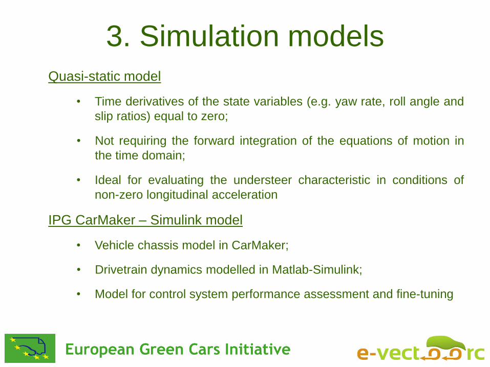
3. Simulation models Quasi-static model
• Not requiring the forward integration of the equations of motion in
the time domain;
• Time derivatives of the state variables (e.g. yaw rate, roll angle and
slip ratios) equal to zero;
• Ideal for evaluating the understeer characteristic in conditions of
non-zero longitudinal acceleration
IPG CarMaker – Simulink model
• Drivetrain dynamics modelled in Matlab-Simulink;
• Vehicle chassis model in CarMaker;
• Model for control system performance assessment and fine-tuning

3. Simulation models

The yaw moment controller presents a hierarchical structure
4. Control Structure
*
,
*
,
*
if
if
*0,
*
dyndynMAXydynMAXyy
dyndyndyny
dyndyn
dyndyn
eakaa
ka
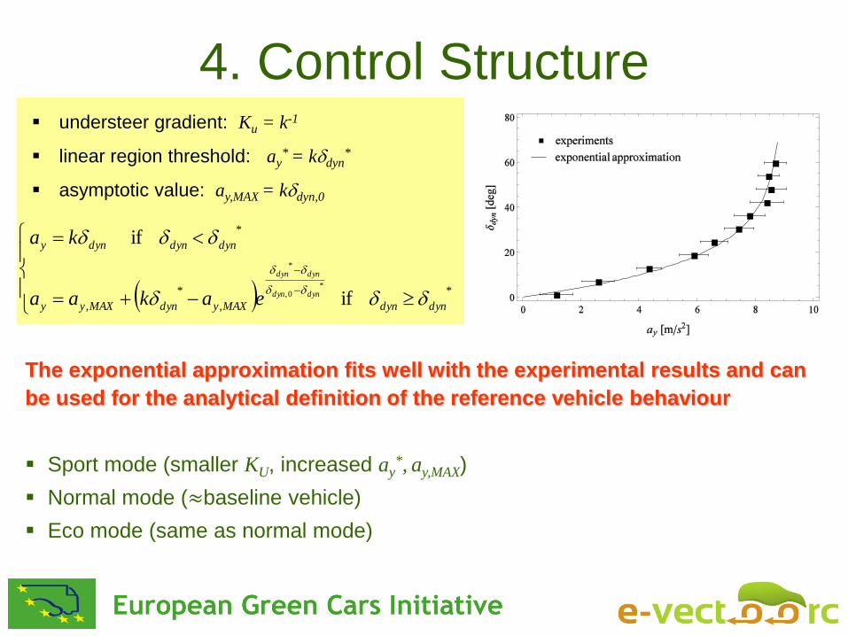
understeer gradient: Ku = k-1
linear region threshold: ay* = kdyn
*
asymptotic value: ay,MAX = kdyn,0
Sport mode (smaller KU, increased ay*, ay,MAX)
Normal mode (≈baseline vehicle)
Eco mode (same as normal mode)
The exponential approximation fits well with the experimental results and can
be used for the analytical definition of the reference vehicle behaviour
4. Control Structure

An optimisation procedure has been developed for achieving the target
understeer characteristic through the feedforward contribution of the yaw
moment
Several objective functions have been implemented
4. Control Structure
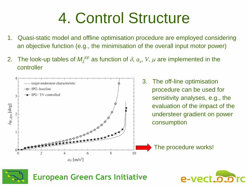
1. Quasi-static model and offline optimisation procedure are employed considering
an objective function (e.g., the minimisation of the overall input motor power)
2. The look-up tables of MzFF as function of , ax, V, m are implemented in the
controller
3. The off-line optimisation
procedure can be used for
sensitivity analyses, e.g., the
evaluation of the impact of the
understeer gradient on power
consumption
The procedure works!
4. Control Structure

Driving mode Understeer characteristic Control Allocation
Normal Normal Squared sum of wheel torque-vertical load ratios
Sport Sport Squared sum of wheel torque-vertical load ratios
Eco Normal Wheel torque ratio from offline optimisation
On-line optimisation methods have been chosen for the 3 driving modes
with differences in the cost function formulation
1) Tyre friction limits
2) Motor/regeneration torque limits
3) Maximum predictive torques
4) Battery (charge/discharge) limits
5) ECE Braking regulations
6) Rate limits
Main constraints for CA
4. Control Structure
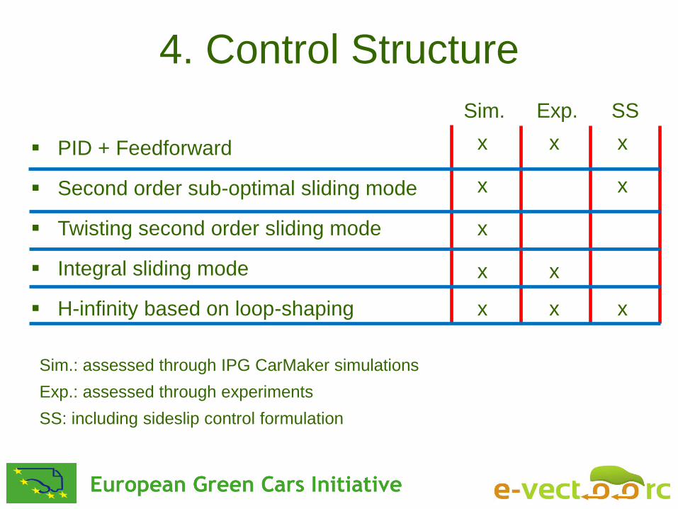
PID + Feedforward
Second order sub-optimal sliding mode
Twisting second order sliding mode
Integral sliding mode
H-infinity based on loop-shaping
Sim. Exp. SS
x x x
x x
x
x x
x x x
Sim.: assessed through IPG CarMaker simulations
Exp.: assessed through experiments
SS: including sideslip control formulation
4. Control Structure

Sub-optimal SOSM
Baseline PID+FF
(V = 90 km/h; pa = 50 %)
De Novellis, Sorniotti, Gruber, Pennycott, “Comparison of Feedback Control Techniques for Torque-Vectoring Control of Fully Electric Vehicles”, IEEE TVT (2014)
5. Simulation-based testing

Lommel proving ground
Skid pad tests (e.g., R = 30, 60 m)
Step steer tests at constant torque demand (e.g., = 100 deg, Vin = 90 km/h)
Frequency response tests at constant torque demand ( = 20 deg, Vin = 50, 90 km/h)
Vehicle modes: baseline, torque-vectoring (sport mode, normal mode, VSC mode)
6. Experimental testing
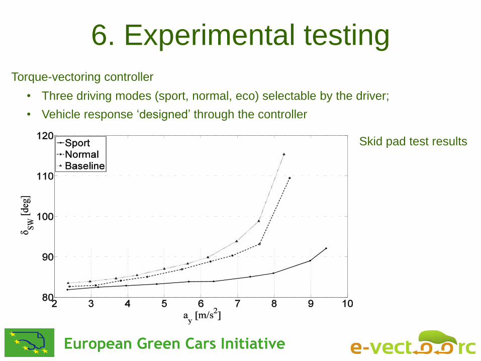
• Three driving modes (sport, normal, eco) selectable by the driver;
Torque-vectoring controller
• Vehicle response ‘designed’ through the controller
Skid pad test results
6. Experimental testing

Skid pad test
results
Step steer results
• Increased yaw damping;
• Reduced delay
6. Experimental testing
Time delay (in s) between the reference yaw rate and the actual yaw rate
7. Conclusions
1. Model-based design of the feedforward contribution of the torque-
vectoring controller;
2. Control structure including feedforward and feedback contributions,
designed for reduced amount of tuning time;
3. Experimental demonstration of the capability of shaping the understeer
characteristic depending on the selected driving mode;
4. Experimental demonstration of the benefits (in terms of increased yaw
damping) of continuous torque-vectoring control actuated through the
electric motor drives with respect to the actuation of the friction brakes in
emergency conditions

Happy to answer questions
www.e-vectoorc.eu
The research leading to these results
has received funding from the European
Union Seventh Framework Programme
FP7/2007-2013 under grant agreement
n°284708
For information do not hesitate to contact Aldo Sorniotti, [email protected]