likaa fahmi ahmed izzat development of brushless self
TRANSCRIPT

ISBN 978-3-86219-018-8
In this work, a developed model of brushless synchronous generator of wound rotor type is designed, analyzed by FEM, practically applied and investigated. A comparison of results with conventional machines is also performed. The presented machine can be applied for multi-pole wind/ hydro generators or double-poles diesel-engine generators. It is self-excited by residual magnetism and a connected capacitor. It is also self-regulated by making use of fluctuations at load or limited speed changes. The generated voltage may last at extended speed range by arranging a generating system with variable capacitance. By eliminating the permanent magnets or advanced manufacturing technology of rotor poles; and without using extra rotating/ external DC exciters, an efficient excitation field and an output of flat self-compensated compound characteristic are obtained. More, the feature of damper windings is determined.
Concerning the fact of environmental diminishing of elements in materials of permanent magnets and D.C. Battery, the presented novel machine is hence a good alternative and more economic from generators, exist in the market. Beside, it is safer and highly recommended for power stability when connected to the grid.
4
Likaa Fahmi Ahmed Izzat
Development of Brushless Self-excited and Self-regulated Synchronous Generating System for Wind and Hydro Generators
4
Lika
a Fa
hmi A
hmed
Izz
at
Elektrische Energiesysteme
Dev
elop
men
t of
Bru
shle
ss S
elf-e
xcit
ed a
nd S
elf-r
egul
ated
Syn
chro
nous
Gen
erat
ing
Sys
tem
for
Win
d an
d H
ydro
Gen
erat
ors
Elektrische Energiesysteme
Band 4 Herausgegeben vom Kompetenzzentrum für Dezentrale Elektrische Energieversorgungstechnik

Development of Brushless Self-excited and Self-regulated Synchronous Generating System for Wind and Hydro Generators
Likaa Fahmi Ahmed Izzat
kasseluniversity
press
This work has been accepted by the Faculty of Electrical Engineering/Computer Science of the University of Kassel as a dissertation for acquiring the academic degree of Doktor der Ingenieurwissenschaften (Dr.-Ing.). Supervisor: Prof. Dr.-Ing. habil. Siegfried Heier Co-Supervisor: Prof. Dr.-Ing. Marcus Ziegler Defense day: 23rd August 2013
Bibliographic information published by Deutsche Nationalbibliothek The Deutsche Nationalbibliothek lists this publication in the Deutsche Nationalbibliografie; detailed bibliographic data is available in the Internet at http://dnb.dnb.de. Zugl.: Kassel, Univ., Diss. 2013 ISBN 978-3-86219-018-8 (print) ISBN 978-3-86219-019-5 (e-book) URN: http://nbn-resolving.de/urn:nbn:de:0002-30193 © 2014, kassel university press GmbH, Kassel www.uni-kassel.de/upress Printing Shop: docupoint GmbH, Barleben Printed in Germany

I dedicate this research work
to my dear parents, my sister and my brother for their
continues encouragement and morally supporting

6
7
Acknowledgements This dissertation has been performed within my work as a Ph.D. student and a scientific researcher in the University of Kassel, Department of Electrical Engineering and Computer Science (FB 16), Institute of Electrical Energy Supply System (IEE-EVS) and the related offices, laboratories, workshops and assistance of some industrial companies in Germany. In addition, it has been supported and partially financed by the Ministry of Higher Education and Scientific Research/ University of Technology in my homeland, Iraq. The conscientious encouragement, valuable helps and suggestions of my supervisor Prof. Dr.-Ing. Habil Siegfried Heier, the expert and chief of the researches section of wind energy technology and a director at Fraunhofer institute for researches in wind energy and energy system technology (Fraunhofer IWES), are gratefully acknowledged. My special thanks go first of all to him; because my ambition to achieve a doctor degree in electrical engineering could not have been a part of successful story in my life without the help and support of his honor as a first supervisor. Beside, I am very much thankful to the recommendations, suggestions, valuable helps and support of the supervisor Prof. Dr.-Ing. Marcus Ziegler, the head of the institute of Electrical Machines and Drives. I would like also to express my pure appreciation and thanks to Prof. Dr.-Ing. Habil Peter Zacharias, the head of the institute of Electrical Energy Supply System (IEE-EVS), a director at the Competence Centre for Distributed Electrical Energy Supply Technology (KDEE) and a director at Fraunhofer Institute for Wind Energy System Technology (Fraunhofer IWES), for his support to my research work and facilitations that has been presented to my project in manufacturing the prototype model and doing experimental tests in the laboratories of the institute. I highly indebted to Mrs. Anja Clark-Carina, director of the secretariat’s office in the Institute IEE-EVS for her continuous assistances and useful advices in the administration issues related to the research project within my study at University of Kassel. Beside, I am very thankful to the help of our colleagues in the Institute, Dipl.-Ing. Adil Ezzahraoui, researcher and employer, Dipl.-Ing. Werner Döring, director of administration office, Mr. Bernhard Siano, technical and administrator to facilitate my research work requirements and in manufacturing the practical model. My thanks and appreciation goes also to Mr. Volker Berge, for his technical support within manufacturing the prototype and his care in every step for safe and successful series of experimental tests of the model at machine laboratory of our Institute.

8
I also adore and thankful to the help and advices of our colleagues in the institute KDEE, Dr. Benjamin Sahan, Dr. Samuel Araujo, M.Sc. Lucas Menezes, M.Sc. Andressa Schittler, Dipl.-Ing. Mehmet Kazanbas and Dipl.-Ing. Manuel Günther, beside the help of colleagues in the Institutes of Electrical Machines and Drive Systems, Mr. Jörg Wiederrecht and Dipl.-Ing. Erhard Schäfer in providing me the instruments needed for accurate laboratory tests and setting the experimental test board for a good machine coupling. In addition, I am very grateful to the engineers, technicians and workers in the electrical engineering and machine engineering workshops at the University of Kassel who have helped me in simplifying and accelerating of manufacturing some parts of prototype machine. More, I appreciate the efforts and thankful to the help of Senior Engineer Mr. Marco Tietz/ ThyssenKrupp Electrical Steel GmbH in providing us an electrical steel pieces for free-cost that helped us in decreasing the cost of manufacturing the new rotor of the prototype machine. Moreover, I appreciate the help and support of Prof. Dr. K. S. Krikor, an expert in electrical machines, Prof. Dr. Talal A. Aljabbar, the head of the institute of Electromechanical Engineering Department and the employees in the University of Technology in Baghdad/ Iraq. Beside the precious advices and assistance of Dr. W. Rudolf, GASP Berlin-Germany during my Ph.D. study is highly acknowledged. Above that, the practical work of this Ph.D. project would not be fully implemented without the positive and helpful cooperation of the expert in national and international companies and suppliers, which are: ByTune Electronics Co., Ltd, China for manufacturing and supplying the slip ring component, Dr Karl Bausch GmbH & Co Kg, Italy for manufacturing the rotor lamination, Minich Elektromaschinenbau GmbH, Kassel, Germany, for impregnating the rotor and stator assembly and for their valuable advices, Kurt Maier Motor Press GmbH for manufacturing the force ventilation unit, the electrical and mechanical work-shop in the University of Kassel and other electromechanical work-shop (Werkstaat) in Kassel – Germany, and also Hopf Vertriebsgesellschaft mbH - Germany for providing the copper wire; beside Antriebstechnik KATT Hessen GmbH, Kienle & Spiess GmbH, Germany for instructions and offers about electrical steel use and manufacturing. Last and not least, words alone can not express the thanks and gratefulness I owe to my dear parents, my sister and my brother in Iraq who are always supporting me, and who are the reason for continuing my study till success.
Likaa Fahmi Ahmed Izzat Kassel, April 1st 2013
9
Summary In relating to grid integration and the need of replacing high price unsustainable sources with renewable energy power sources, this research project presents a developed design model of brushless synchronous generator of wound rotor type and a generating system that can be applied for multi-pole wind/ hydro energy plants generators beside normal double-pole diesel-engine generators. The generator is capacitive self-excited starting from residual magnetism and self-regulated making use of fluctuations at loads or limited speed changes. More, the voltage generation at extended speed range may last by arranging the generating system with variable capacitance through simple control circuit. Above that the presented brushless capacitor-excited synchronous generator (BCESG) has an efficient excitation field and flat self-compensated compound characteristics, without permanent magnets and advanced manufacturing technology for rotor poles; and without using extra rotating/ external DC exciter. It also has features of synchronous machines with damper windings. In this dissertation, the state of the art is comprehensively studied. Based on generalized machine theory and finite element method (FEM), the analysis, design and performance computations are implemented. The CAD construction plots are prepared. Electromagnetic simulation, numerical static and dynamic analysis and response study are applied to obtain design parameters, electromagnetic forces and machine characteristics, by using ANSOFT-MAXWELL, RMxprt and QUICKFIELD software. An electronic control circuit is designed and the signals and waveforms are detected using MULTISIM, electronic-components software. Comparison with analysis and simulation of previous model (the author previous work) and other conventional types, such as salient-pole and non-salient poles synchronous machines are made. To investigate the self-excitation and magnetic fields developments, the animation of electromagnetic model is also illustrated. In practical part, new rotor-lamination stamps are manufactured and a prototype machine of size 10 kVA, 6 poles with changeable capability of phase/ pole numbers, is manually assembled and tested by the author in machine laboratory of the institute KDEE/ EVS (Power Supply System) at University of Kassel. The experimental results are compared with the data of theoretical calculations, simulation and response analysis. More, the measured data are compared with the practical test data of DC excited salient-pole synchronous generator and previous model of BCESG. But the load value till only half of full-load is achieved; because the rotor mechanical tolerances and balance has not been certified. At half of full-load, a fair correspondence between theoretical and practical results is occurred.
10
At load changes, the test-machine shows a stable operation and less mechanical noise. The generator is self-excited and regulated at single-phase and three-phase operation. Depending on load value, type and winding distribution, the resultant percentage harmonic distortion is 6.76 % with efficiency 84% at a half of full load and a measured maximum frame temperature of 48.4 °C, after 2 hours of operation. By increasing the load, the excitation is increased and the output wave is improved. Also, the ripples decrease by using suitable capacitor-filter or a stepped winding distribution with specific slot skewing angle. The output voltage is directly affected by variations in value of capacitor. A strong self-excitation at a resonance capacitor value is performed. Finally, it has been investigated that the proposed developed model creates also a maintained magnetic field at rotor main poles, similar to the case of conventional DC-excited or permanent-magnet synchronous generators. This is because both half-wave and full-wave rectified current components are induced in rotor field winding of the presented contact-less machine, in contrast to previous brushless model which have only half-wave rectified rotor currents. The presented machine is simple, robust, reliable, maintenance free and applicable with good efficiency and considerable cost for single or three phase generator design. Knowing that the chemical elements of materials of permanent-magnets and D.C. Battery are getting to diminish from the environment in a couple of decades; this developed BCESG might then be considered as a good alternative and more economic from the existent types of generators. Beside, it is safer at renewable energy applications and highly recommended for power stability when connected to the grid.

11
Zusammenfassung Im Hinblick auf eine verstärkte Anwendung und Netzintegration erneuerbare Energien in der elektrischen Energieversorgung bietet die im Rahmen der Dissertation entwickelte, konstruierte, aufgebaute und messtechnisch untersuchte bürstenlose Synchronmaschine völlig neuartige Perspektiven. Ihr Einsatz ist sowohl bei konventionellen Dieselaggregaten wie auch bei Wind- und Wasserkraftanlagen möglich. Der Generator ist kapazitiv selbsterregt und selbstgeregelt und nutzt die ausgleichende Wirkung, die Schwankungen bei Belastungs- oder Geschwindigkeitsänderungen innerhalb begrenzter Bereiche hervorrufen. Darüber hinaus hat der vorgestellte bürstenlose Kondensator erregte Synchrongenerator (BCESG) die zusätzlich Funktion von Maschinen mit Dämpferwicklungen, die selbstausgleichende Charakteristik aufweisen und zur Netzstabilität beitragen. Der Synchrongenerator besteht aus einem Schenkelpol-Läufer mit Querfeldwicklungsnuten in den Polen und einem herkömmlichen Stator. Beide sind aus laminiertem Elektroblech hergestellt und mit Wicklungen versehen. Der Rotor hat zwei getrennte Kupferwicklungen für die jeweiligen magnetischen Haupt- (direct axis) und Querfeld- (quadrature axis) - Richtungen. Die Querfeldwicklung, die in Nuten der jeweiligen Pole untergebraucht ist und von der Statorseite erregt wird, versorgt über Dioden - Brückengleichrichter die Hauptfeldwicklung. Der Phasenverschiebungswinkels zwischen den Feldern in beiden Wicklungen sollte vorzugsweise nahe bei 90 Grad (elektrisch) liegen. Die Statornuten sind gleichmäßig verteilt, wie in einem traditionellen Ständerdesign. Zusätzlich zu den üblichen einphasigen oder mehrphasigen Lastwicklungen ist eine weitere Wicklung kondensatorerregt ausgeführt. Im Hauptrotorfeld werden daher bei Lastwechsel- und (begrenzten) Nenndrehzahl-Änderungen die elektromagnetischen Felder und induzierten Spannungen von diesem Generator weitestgehend selbst ausgeregelt. Das System ist weiterhin mit einer elektronischen Regelung versehen, die die Ausgangsspannung des Generators und Veränderungen der Drehzahl überwacht und ausgleicht. Somit werden Generatorspannung und Drehzahl im Bereich zwischen dem oberen und unteren Grenzwert reguliert und eingehalten. In Rahmen dieser Arbeit werden Analyse, Design und Leistungs-Berechnungen für den entwickelten BCESG umgesetzt, die auf der allgemeinen Maschinentheorie

12
und auf Maxwell-Gleichungen basieren. Elektromagnetische FEM-Simulationen, numerische, statische und dynamische Analysen werden zur Untersuchung der Maschine angewandt. Diese Untersuchungen werden mit Hilfe von ANSOFT-MAXWELL, RMxprt und QUICKFIELD Software durchgeführt. Die Steuerschaltung etc. werden unter Verwendung von MULTISIM entworfen. Die Ergebnisse der Untersuchungen der entwickelten Maschine werden mit Hilfe von Simulationen und Analysen von anderen herkömmlichen Bauarten, wie Schenkelpol- und Vollpolsynchronmaschinen verglichen. Um die Selbsterregung der magnetischen Felder zu untersuchen wird eine elektromagnetische Animation des Modell-Generators angewandt. Der praktische Teil der Arbeit umfasst sowohl den mechanischen Aufbau als auch die Ausführung und Einlegung der Stator- und Läuferwicklungen in einer 6 polig ausgeführten 10 kVA – Prototypenmaschine. Zusammenbau und messtechnische Untersuchungen der Maschine wurden in der Maschinenhalle des Fachgebietes Elektrische Energieversorgungssysteme an der Universität Kassel durchgeführt. Als Antrieb wurde ein drehzahl- bzw. drehmomentgeregelter Gleichstromantrieb (200kW) verwendet. In der Prototyp-Maschine wurden die Spulenklemmen der Ständer- und Läuferwicklungen auf einen Schaltkasten verlegt, um Änderungen der Verbindungen zu ermöglichen und damit die Zahl der Phasen, der Windungen pro Phase, verschiedene Polzahlen oder andere Schaltungsverbindungen ohne Maschinendemontage zu ermöglichen. Bei Nenndrehzahl wurden das Drehmoment, die Spannungen, Ströme, Schein-, Blind- und Wirk-Leistung sowie Wellenformen und Harmonische von Ständer- und Läuferwicklungen gemessen, aufgezeichnet und graphisch durch digitale Drehmoment-Messung, Power Analyzer und andere Messgeräte dargestellt. Auch der Temperaturanstieg wurde stets gemessen und überwacht. Die Daten wurden mittels Speichertools gespeichert und mit einer digitalen Kamera dokumentiert. Die Messergebnisse des vorgestellten Prototyps werden mit den theoretischen Daten der Simulation verglichen. Darüber hinaus werden die experimentellen Daten mit den praktischen Ergebnissen von zusätzlichen Tests des Vorgängermodells BCESG, für die zwei separate Dioden an getrennten Läuferwicklungen verwendet wurden, zum Vergleich herangezogen. Die Messungen wurden mit einer variablen, (hauptsächlich) ohmschen Last für die Testmaschine an den Einphasen- oder Mehrphasen-Ständerwicklungen bis etwa halbem Volllastbetrieb vorgenommen. Höhere Lasten wurden vermieden da die Läuferbleche sehr große Fertigungstoleranzen aufweisen und die Maschine bei hohen Lasten zu mechanischen Schwingungen neigte. Eine induktive Belastung bis 80 % des Leistungsfaktors wurde ebenfalls durchgeführt. Darüber hinaus wurde
13
der Prototyp für den Phasenverschiebungswinkel von weniger als 90 Grad elektrisch zwischen den Achsen der Ständer-, und Erreger-Wicklung getestet. Die Anzahl der Pole wurde zwischen vier, acht und zwölf variiert. Außerdem wurde der Betrieb unter- und oberhalb der Nenndrehzahl getestet und die Selbsterregung bei umgekehrter Drehrichtung untersucht. Bei Lastwechsel zeigt die Test-Maschine einen stabilen Betrieb (weniger mechanische Geräusche). Die Ausgangsspannung ist mit kompensierenden Eigenschaften sehr flach ausgeprägt. Die Selbstregelung der Maschine wird in einem großen Bereich von Lastwechseln, vorzugsweise bei einem Phasenverschiebungswinkel von 90 Grad (elektrisch) zwischen Ständerlast- und Erreger-Wicklung für einphasige Maschinen und mehrphasige Maschinen, erreicht. Der Generator hält auch bei unsymmetrischen Lasten die Selbsterregung aufrecht. Um die Selbstregelung für die Mehrphasen-Maschine ebenfalls zu erhalten, müssen die Rotornuten in den Polen so erhöht werden, so dass die Anzahl der Hilfsphasen-Läuferwicklung der Anzahl der Ständer-Lastwicklung entspricht. Die Selbst-Erregung dieses entwickelten bürstenlosen Synchrongenerators vollzieht sich schnell bei nahezu konstantem Hauptrotorfeld, solange der Restmagnetismus und der abgestimmte Kondensator-Erreger vorhanden sind. Abhängig von der Art der Last und der Verteilung der Ständerwicklungen liegt die harmonische Verzerrung bei Halblast bei ca. 6,76%. Dabei wird ein Wirkungsgrad von annähernden 84% bei einer maximalen Temperatur von 48,4 °C nach zwei Stunden Betriebsdauer erreicht. Durch die Erhöhung der Last wird die Wellenform verbessert. Auf der anderen Seite wird die Welligkeit der Ausgangsgrößen mithilfe eines geeigneten Kondensator-Filters oder durch eine Verbesserung des Verteilungsfaktors der Ständerwicklungen mit geeigneter Nutschrägung verringert. Die Ausgangsspannungen sind direkt betroffen und variieren proportional den geänderten Werten der zugeschalteten Kondensator-Erreger oder Kondensator-Filter. Ohne Last kann die Nenn-Ausgangsspannung auch durch die Wirkung der hohen Welligkeit am Ausgang stark reduziert werden, auch wenn der Wert des Kondensator-Erregers niedrig ist. Eine schwache Selbsterregung ist jedoch die Folge, die bei Lastbetrieb verschwinden kann. Starke Selbsterregung und ein stabiler Betrieb werden durch Kondensator-Werte erreicht, die auf abgestimmte Resonanzkreise und eine Auslegung der Maschine nahe der Sättigung führen. Die Darstellungen in dieser Dissertation sind besonders auf die Präsentation der praktischen Ergebnisse ausgerichtet, die den Betrieb der entwickelten BCESG umfassen. Im Rahmen der Untersuchungen konnte eine gute Übereinstimmung zwischen theoretischen und praktischen Ergebnissen feststellt werden. Die
14
Dissertation stellt somit die Basis für weitergehende Forschungs- und Entwicklungsarbeiten dar, die
- Selbstregelungseffekte und-
- Spannung- bzw. Frequenzregelungskonzepte sowie - Untersuchungen von netzstabilisierenden Effekten von großen,
leistungsstarken BCESG im Verbundnetzbetrieb umfassen und somit den Generator einem großtechnischen Einsatz näher bringt.

15
Contents Acknowledgments 7 Summery 9 Zusammenfassung 11 Contents 15 Chapter 1 - General Introduction 23 1.1 Wind generating systems and problems formulation 23 1.2 Research objectives 29 1.3 Methodology 29 1.4 Dissertation structure 30 Chapter 2 - Brushless Synchronous Generating Systems 33 2.1 General structure of brushless capacitor-exciter synchronous
generator (BCESG) 33 2.1.1 Basic construction 33 2.1.1.1 Rotor assembly 33 2.1.1.2 Stator assembly with low-power electronic
circuit (LPEC) 35 2.1.2 Description and operation of BCESG system 35 2.2 The state of the art and comparison with other operation concepts 43 2.2.1 Brushless cylindrical-rotor type synchronous generator 43 2.2.2 Synchronous generator with arrangement for brushless
excitation 44 2.2.3 Capacitor-excitation variable-resistor brushless
synchronous generator 45 2.2.4 Thermally sensitive-resistance type brushless
synchronous generator 46 2.2.5 Brushless single-phase synchronous generator with A.C.
exciter 47 2.2.6 Inductor type brushless generator (ITBG) 48 2.2.6.1 Construction and winding arrangements of
ITBG 48 2.2.6.2 Voltage compensation arrangement of
multiphase ITBG 49 2.2.7 Brushless synchronous generator utilizing the 5th-space
harmonic component 50 2.2.8 Brushless synchronous machine using amortisseur
windings 51
16
2.2.9 Brushless cylindrical-rotor synchronous generator 52 2.2.10 Brushless single-phase synchronous generator 53 2.2.11 Brushless generator with a novel voltage regulator 55 2.3 Main features of the presented developed BCESG 56 Chapter 3 - Comprehensive Analysis, Parameters and Characteristics 57 3.1 Developed brushless capacitor-exciter synchronous generator
(BCESG) 57 3.1.1 The features in analyzing the developed BCESG 58 3.1.2 The assumptions in analyzing the developed BCESG 61 3.2 The voltage equations of developed BCESG Model 62 3.3 Comparison with the improved self-excited synchronous generator
(BSESG) Model 66 3.4 Flux linkage of developed BCESG 68 3.5 No-load characteristics 71 3.5.1 Approximate solution of currents 71 3.5.2 Determination of field flux and angle between load
winding & rotor direct axis 75 3.5.3 The nonlinearity due to saturation of magnetic circuit 78 3.5.4 Discussion of generation condition and capacitor value at
harmonics waves 80 3.5.5 Waveforms of voltages and currents of developed
BCESG 82 3.5.5.1 No-load induced voltage (el0) 82 3.5.5.2 Capacitor induced voltage at no-load (ec0) 84 3.5.5.3 Instantaneous capacitor current (ic) 84 3.5.5.4 Rotor windings currents (Irm, ira) 85 3.5.6 Conclusions of analysis at no load condition 86 3.6 Analysis of load characteristics 86 3.6.1 Voltage and flux relations at boundary condition 86 3.6.2 Instantaneous load and capacitor currents 89 3.6.3 Determination of angle ( δ + ϑl1 ) 90 3.6.4 Main and auxiliary rotor induced currents at load
operation 90 3.6.5 Separation of angles ϑl1 and δ at load condition 91 3.6.6 Main and auxiliary rotor linkage fluxes at load operation 93 3.7 Instantaneous load and capacitor voltages 94 3.7.1 Terminal load voltage (vl ) 94 3.7.2 Terminal capacitor voltage (vc) 94 3.8 Determination of the saturation coefficient “Xcf
2/Xf ” at load condition 95
3.9 Characteristics study and comparison 95

17
3.9.1 Analytical study of previous primarily BSESG model 95 3.9.2 Analytical study of the improved BSESG model 95 3.9.3 Characteristics of the presented developed BSESG model 98 3.10 Discussion of characteristics for three types of capacitor-exciter
generators 99 Chapter 4 - Design Computations of BCESG and Comparison of
Theoretical Results with Conventional Designs of Synchronous Machines 103
4.1 Multi-phase design model of developed BCESG 105 4.1.1 Two-phase machine 105 4.1.2 Three-phase machine 107 4.1.3 Discussion of multi-phase BCESG operation 107 4.2 Approximate equivalent circuit 109 4.3 Time vector diagram 110 4.4 Choosing the electrical-materials 110 4.4.1 Conducting materials 111 4.4.2 Insulating materials 111 4.4.2.1 Insulation for conductor coating 111 4.4.2.2 Insulating resin and varnish 111 4.4.3 Magnetic materials - Silicon steel 112 4.5 Design procedure for BCESG 113 4.5.1 The machine active parts 113 4.5.1.1 Importance of specific loadings 116 4.5.1.2 Separation of stator core length and inner
stator diameter 116 4.5.2 Air-gap length and the importance of SNSP rotor
construction 117 4.5.3 Rotor inner diameter and stator outer diameter 118 4.5.4 Slot design 119 4.5.4.1 Stator slot 120 4.5.4.2 Rotor slots 121 4.5.5 Windings design 124 4.5.5.1 Stator load winding 125 4.5.5.2 Stator capacitor-exciter winding 126 4.5.5.3 Rotor main field winding 126 4.5.5.4 Rotor auxiliary winding 128 4.6 Elimination of harmonics 129 4.7 Magnetic circuit of BCESG 130 4.7.1 The magnetic flux density (B) 130 4.7.1.1 B at the air-gap 130 4.7.1.2 B of the stator and rotor teeth 131
18
4.7.1.3 B of the stator and rotor core 131 4.7.2 Magneto-motive force (AT) 132 4.7.2.1 AT in the air-gap 132 4.7.2.2 AT at the stator and rotor teeth 132 4.7.2.3 AT of the stator and rotor core 132 4.7.3 The saturation factor and magnetization current 133 4.8 Machine parameters 134 4.8.1 Winding resistance 134 4.8.1.1 Resistance of stator Windings 134 4.8.1.2 Resistance of rotor Windings 135 4.8.2 Leakage reactance 136 4.8.2.1 Leakage reactance at stator side 136 4.8.2.2 Leakage reactance at rotor side 137 4.8.3 Magnetization reactance 138 4.8.3.1 Direct-axis synchronous reactance (XD) 138 4.8.3.2 Quadrate-axis synchronous reactance (XQ) 140 4.8.4 Field winding reactance (Xf) 140 4.9 Power losses and efficiency calculation of BCESG 141 4.9.1 Copper losses 141 4.9.2 Iron losses 141 4.9.3 Additional power losses 143 4.10 Efficiency and rotating torque 143 4.11 Application of design for a prototype 10 kW, 6 poles BCESG Model 144 4.11.1 Dimensions of stator 144 4.11.2 Air-gap and dimensions of rotor 146 4.11.3 Windings distribution 149 4.12 Design results for BCESG and design sheet of generators at markets 154 4.12.1 Results of magnetic circuit, parameters and performance
of BCESG 154 4.12.2 Design of salient pole synchronous generator using
ANSOFT-RMxprt 159 4.12.3 Design of non-salient pole synchronous generator using
ANSOFT-RMxprt 161 4.13 Conclusions from results comparison and discussion 164 Chapter 5 - Electromagnetic Simulation of BCESG and Response Study
Compared to Simulation Results of Machines at Markets 167 5.1 Comparison of analysis methods 167 5.1.1 Finite element method, FEM 167 5.1.2 Boundary element method, BEM 168 5.1.3 Hybrid element method 168 5.2 Steady-state analysis, post processing and comparison results 169
19
5.2.1 Magneto-static simulation of developed BCESG , salient poles and non-salient poles synchronous machines 169
5.2.1.1 Magnetic field lines and mesh implementation 169 5.2.1.2 Magnetic flux density and potential
distribution 169 5.2.1.3 Current density distribution and field intensity 174 5.2.2 Electromagnetic characteristics of developed BCESG and
comparison study 174 5.2.2.1 Magnetic potential and flux density 174 5.2.2.2 Harmonics study and potential approximation 179 5.2.2.3 Field strength and energy density 180 5.2.3 Inductances and magnetic coefficients 180 5.3 Dynamic analysis and response study of BCESG and synchronous
machines of markets 181 5.3.1 Electromagnetic model simulation of BCESG, SPSG and
NSPSG 182 5.3.2 Transient response at rated load & comparison study
between four types of SGs 186 5.3.2.1 Sub-transient, transient and steady statuses 187 5.3.2.2 Core loss, magnetic force and torque 192 5.3.2.3 Self and mutual inductances at transient state 194 5.3.3 Response at short circuit and no-load conditions 195 5.4 Discussion of main features and importance of developed BCESG 200 Chapter 6 - Prototype Machine and Experimental Results 203 6.1 Manufacturing general prototype of developed BCESG machine 203 6.1.1 Stator and SNSP rotor core 203 6.1.2 Armature and field windings for multiphase design 205 6.2 General setup for experimental test of the prototype synchronous
machine 205 6.2.1 Initial test with reduced voltages at no-load operation 206 6.2.1.1 Test with D.C. field exciter 206 6.2.1.2 Test with D.C. exciter and capacitor at
auxiliary stator winding 210 6.2.1.3 Test with D.C. field and additional capacitors
at stator windings 211 6.2.2 Load test with reduced-voltage 212 6.2.2.1 Experimental test at load operation with D.C.
exciter field 212 6.2.2.2 Test with D.C. and A.C. supply on rotor
windings 213 6.3 Experimental measurements of developed model of BCESG 215
20
6.3.1 Investigation of characteristics at no-load/ load operation 215 6.3.2 Investigation of performance at capacitor changes 219 6.3.3 Comparing of practical results with response analysis
results at half-load 222 6.4 Experimental test of previous model of BCESG 224 6.5 Comparison of practical results between conventional SG and
BCESGs types 227 6.6 Discussion and conclusion from practical results 228 Chapter 7 - Wind/Hydro Fluctuation Solver (LPEC) 231 7.1 Description and design of the integrated control circuit 231 7.2 Operation and response simulation 232 7.3 Discussion of generating system with LPEC device 234 Chapter 8 - General Conclusions and Future Outlook 235 8.1 Descriptions and final conclusions of the presented research project 235 8.2 Advanced concepts and future work 237 Appendixes 239 Appendix A: Analytical Derivations of the Developed BCESG 240 A-1 Flux linkages 240 A.1.1 Solution for φl 240 A.1.2 Solution for φc 240 A.2 Determination of current components Ic1 , Ic3 and Ic5 241 A.3 Determination of (d Irm / dt) at boundary condition 243 A.4 Determinant equation of δ 243 A.4.1 First derivation 243 A.4.2 Second derivation 244 A.5 Determination of (d φfd / dδ) and (d2 φfd / dδ2) 244 A.6 The solution to obtain the value of “ δ ” 245 A.7 Values of capacitor reactance and generation modes 245 A.7.1 The condition at capacitor reactance XC5 245 A.7.2 The condition at capacitor reactance XC3 245 A.7.3 The condition at fundamental capacitor reactance XC 246 A.8 Induced generator voltage el0 247 A.9 Induced capacitor voltage ec0 247 A.10 Determination of rotor currents 248 A.11 Voltage and current relations 248 A.11.1 Load circuit 248 A.11.2 Capacitor circuit 249 A.11.3 Investigation of stator induced currents 250
21
A.12 Determination of rotor currents at load condition 250 A.12.1 Determination of induced current Irm 250 A.12.2 Determination of induced current ira 251 A.13 Power factor and load angle 252 A.13.1 Determination of angle “ ϑl1 - δ ” referring to load circuit 252 A.13.2 Investigation of angle “ϑl1 - δ ” referring to capacitor
circuit 254 A.14 Determination of rotor field fluxes at load condition 255 A.14.1 Determination of “φfd ” 255 A.14.2 Determination of “φfq ” 255 A.15 The relation between “Xcf
2/Xf ” and XC at load condition 256 A.16 Analytical relations of previous primarily BSESG model at load
condition 257 A.17 Analytical relations of improved BSESG model 258 Appendix B: Engineering Design of the Prototype Machine 260 B.1 Electrical materials 260 B.2 Standards magnetic materials 261 B.3 Slot permeance 263 B.4 Prototype-BCESG plots of designed parts and subassemblies 264 B.4.1 Two-scale stator lamination 264 B.4.2 Two-scale rotor-shaft subassembly 265 B.5 Standard dimensions and frame sizes 265 B.6 Determination of rotor slots area 266 B.6.1 Slot area type-S2n 266 B.6.2 Slot area type-S2s 266 B.7 General assembly of BCESG machine 267 B.8 Design data results of two types of synchronous generators, using
ANSOFT-RMxprt 268 B.8.1 Design sheet of salient-pole synchronous machine of size
10kW×1000rpm 268 B.8.2 Design sheet of non-salient-pole synchronous machine of
size 10kW×1000rpm 271 Appendix C: Maxwell’s Equations Tree and Response Study 275 C.1 Integral form 276 C.2 Differential form 276 C.3 The wave equation 277 C.4 Charge Conversation 277 C.5 Harmonics amplitudes and phase angles 278 C.6 Layout of Maxwell software regarding to inductances and magnetic
coefficients 278

22
C.7 Comparison of periodic output between developed & previous BCESG, SPSG & NSPSG 280
C.8 Magnetic force study and response plots 281 C.9 Self and mutual inductances in previous BCESG, SPSG and NSPSG 282 Appendix D: Documentation & Description of Practical Steps of
Manufacturing the Prototype Synchronous Machine, 10kW-6poles 285
D.1 Photographic description of manufacturing the generator (The author work) 285
D.2 Circuit connection diagram for practical test with D.C. and A.C. exciter supply 287
D.3 Experimental test description and results for developed BCESG 287 D.4 Results of transient analysis for two seconds at half-load state of
developed BCESG 288 D.5 The complete electronic circuit (LPEC) built for developed BCESG 290 Bibliography 291 Symbols and Abbreviations 297 List of Figures 307 List of Tables 312
23
Chapter 1
General Introduction
In recent years, the increasing concerns to environmental issues demand the search for more sustainable electrical sources. Wind energy is one of the most flexible and tractable of all available energy sources, since the mechanical energy is directly derived and can be readily and efficiently converted to other forms of energy [1]. Beside, the wind power is increasingly considered as not only a means to reduce the CO2 emissions generated by traditional fossil fuel fired utilities but also a promising economic alternative in areas with appropriate wind speeds. Albeit wind energy currently supplies only a fraction of the total power demand relative to the fossil fuel fired based conventional energy source in most parts of the world, statistical data show that in Northern Germany, Denmark or on the Swedish Island of Gotland, wind energy supplies a significant amount of the total energy demand [2]. The presented study and research work is getting benefit from wind and hydro energy efficiently and economically in a developed design of self excited and regulated brushless synchronous generating system. It is though, self-compensated and keeps stable operation at load fluctuations and considerable speed ranges. Based on finite element method FEM and analytical design performance, the experimental measurements results of 10 kW, 6-poles prototype machine are fairly identical to the theoretical results. The main conclusions of this research project imply that the designing idea can be easily applied from several kilowatts to several hundreds of kilowatts and from two to multi poles machine. It can be developed furthermore for a new machine design of self-regulated output frequency against variations in rotational speed. 1.1 Wind generating systems and problems formulation The development of modern wind power conversion technology has been going on since 1970s. Various wind turbine concepts have been developed and different wind generators have been built. Three types of typical generator systems for large wind turbines exist [3]. The first type is a fixed-speed wind turbine system using a multi-stage gearbox and a standard squirrel-cage induction generator (SCIG) with a capacitor bank for reactive power compensation, directly connected to the grid through a transformer as illustrated in Fig.1-1. A pole-changeable SCIG has been used, which leads two rotation speeds. The second type is a variable speed wind turbine system with a partial-scale power converter and a multi-stage gearbox and

24
a doubly fed induction generator (DFIG), where the power electronic converter feeding the rotor winding has a power rating of ~30% of the generator capacity; the stator winding is also directly connected to the grid as illustrated in Fig.1-2. The DFIG configuration corresponds to a limited variable speed wind turbine with a wound rotor induction generator (WRIG) and Optislip concept [4].
Fig.1-1: Scheme of a gearbox SCIG system Fig.1-2: Scheme of a gearbox DFIG system The SCIG for a fixed speed wind turbine concept is robust, easy and relatively cheap for mass production. It provides a stable control frequency at constant speed operation when it is connected to a large grid. While the disadvantages are as follows: - It is necessary to obtain the excitation current from the stator terminal of SCIG. This makes it impossible to support grid voltage control. - A higher dissipation of electrical energy in the rotor bars. - The speed is not controllable and variable only over a very narrow range, in which only speeds higher than the synchronous speed are possible for generator operation. Beside, the pole-changeable SCIG does not provide continuous speed variations. - The wind speed fluctuations and the electromechanical torque variations cause high mechanical and fatigue stresses and may result in swing oscillations between turbine and generator shaft. Also the periodical torque dips because of the tower shadow and shear effect are not damped by speed variations and result in higher flicker. Finally a three-stage gearbox represents a large mass and a large fraction of the investment costs. Typically, the variable speed range of DFIG system is ±30% around the synchronous speed. Since the rating of the power electronic converter is only 25–30% of the generator capacity, this concept is attractive and popular from an economic point of view. The largest capacity for the commercial wind turbine product with DFIG has been up to 5 MW. Compared with the Optislip concept, the rotor energy, instead of being dissipated, can be fed into the grid by the power electronic converter. Moreover, the power converter system can perform reactive power compensation and smooth grid connection independently of the generator operation; this allows the performance of voltage support towards the grid. However, the DFIG system has the following disadvantages:

25
- The slip ring is used to transfer the rotor power, which requires a regular maintenance, and maybe result in machine failures and electrical losses. - Under grid fault conditions, on the one hand, large stator currents result in large rotor currents, so that the power electronic converter needs to be protected; on the other hand, large stator peak currents may cause high torque loads on the drive train of wind turbines. - A ride-through capability of DFIG is also required according to wind turbines grid connection in case of grid disturbances, so that the corresponding control strategies may be complicated. - Above all, a multi-stage gearbox is still necessary in the drive train because the speed range for DFIG is far from a common turbine speed of 10–25 rpm. A gearbox is inevitable to have some drawbacks, such as heat dissipation from friction, regular maintenance and audible noise [2][3]. The third type is also a variable speed wind turbine, but it is a gearless wind turbine system with a direct-drive generator, normally a low-speed high-torque synchronous generator and a full-scale power electronic converter are used. This generator is connected to the grid through the power converter. Basically, types of direct-drive generators used in the market can be classified into the electrically excited synchronous generator (EESG) and the permanent magnetic synchronous generator (PMSG). The scheme of each is illustrated in Fig.1-3 and Fig.1-4. The most important difference between geared drive wind turbines and direct-drive types is the generator rotor speed. The direct-drive generator rotates at a low speed, because the generator rotor is directly connected on the hub of the turbine rotor. To deliver a certain power, the low speed and high torque operation require multi-poles, which demand a larger diameter and a reasonable small pole-pitch for increasing the efficiency, reducing the weight of active parts and keeping the end winding losses small.
Fig.1-3: Scheme of a direct-drive EESG system Fig.1-4: Scheme of a direct-drive PMSG system Moreover, considering on the current loading and gap flux density limitations, a higher torque also requires a larger machine’s volume, so that the torque density could not be further significantly increased. In addition, the advantages of direct-drive wind turbines are the simplified drive train, the high overall efficiency, the high reliability and availability by omitting the gearbox.
26
Compared with the variable speed concept of a partial-scale power converter, the full-scale power converter can perform smooth grid connection over the entire speed range. However, it has higher cost and power loss in the power electronics, since all the generated power has to pass through the power converter. In EESG, It is necessary to excite the rotor winding with D.C., using slip rings and brushes, or brushless exciter, employing a rotating rectifier and the field losses are inevitable. In compare, the PM machines are lighter with higher power to weight ratio, higher in efficiency and energy yield, higher in reliability due to the absence of slip rings and have improved thermal characteristics due to the absence of the field losses and require no additional power supply for the magnetic field excitation. Three types of PM machines are designed to solve the problems of cogging torque, noise of slotted parts, axial length, torque to volume ratio, copper losses and so on. These types are radial-flux PM machines (RFPM), axial-flux PM (AFPM) and transversal-flux PM (TFPM). However, the main disadvantages of PMSGs are the high cost of PM materials, difficulties to handle in manufacture and the demagnetization of PM at high temperature [2, 4]. The variable speed single-stage geared concept with PMSG and a full-scale power converter, which was introduced as the Multibrid, has gained the attention because it has the advantages of a higher speed than the direct-drive concept and a lower mechanical component than the multiple-stage gearbox concept. Furthermore, the Clipper system, a single-stage gearbox with multiple output shafts that drive a number of medium speed, medium-torque PMSGs, has also been introduced. Each of generator outputs is connected to a dedicated power electronic converter [6]. Additionally, a variety of innovative concepts of wind turbines appear, for example, an interesting alternative may be a mixed solution with a gearbox and a smaller low speed PMSG or variable speed wind turbine with SCIG and full-scale power converter, in order to reduce the generator’s volume and improve the generator efficiency. Compared with the mentioned above DFIG system, this PMSG wind generator has the advantages of better efficiency, brushless design and less complex grid-fault ride-through capability. While the disadvantages are the larger, more expensive converter (100% of rated power instead of 30%) and higher losses in the converter power electronic components. The alternative SCIG system fulfills the variable speed operation and might replace the capacitor bank and soft-starter in the mentioned fixed speed concept system. So the flexible control with a full-scale power provides such a variable speed operation, better performances of reactive power compensation and smooth grid connection. However, its
27
disadvantage is the high cost and low efficiency due to whole system losses (gearbox, induction generator and full-scale converter). Many other potential types of wind generators for different wind turbine concepts are also mentioned in literatures, such as linear induction generators [7], switched reluctance generators [8], claw-pole generators [9] and brushless DFIG [10]. Among them, the BDFIG may be one of the most innovative types, where its system has the capability of realizing the variable speed operation and independently controls the stator active and reactive power. In configuration of direct grid connection, the BDFIG output frequency must be equal to the grid frequency. It requires double stator windings, with different number of poles in both stator layers. The second stator layer generally has lower copper mass, because only a part of the generator nominal current flows in the second winding. This second stator winding is connected through a power electronic converter, which is rated at only a fraction of the wind turbine rating. Compared with the DFIG system, this concept does not require slip rings; however, the machine operation principle and its assembly are relatively complex. From main dimensions and performances comparison, the following conclusions can be summarized [3], as in the following: - Considering the aspects of size and weight, the outer diameter of the direct-drive wind generator is usually larger than the geared-drive generator, but the total length is shorter. From the parts of wind turbine blade, the total weight of wind turbine systems may have no big difference between a three stage (3G) geared-drive configuration and a direct-drive PMSG solution. - DFIG 3G is the lightest and low-cost solution with standard components. - For direct-drive (DD) wind turbine topologies, PMSG DD has the highest energy yield; EESG DD appears to be the heaviest and the most expensive solution. - A solution with DFIG 1G seems to be the most interesting choice because of the highest annual energy yield divided by cost and the lowest generator system cost. PMSG 1G has a better performance than PMSG DD with respect to the energy yield per cost. Based on the mentioned above, various criteria may be used for comparing different wind generator systems, including the torque density, the cost per torque, the efficiency, the active material weight, the outer diameter, the total length, the total volume, the total generator cost, the annual energy yield, the energy yield per cost, the cost of energy and the cost-effective machines [1][2][3]. An overall and practical comparison of different wind generator systems, including techniques, Economy, control function, availability and reliability, may require to be further investigated.
28
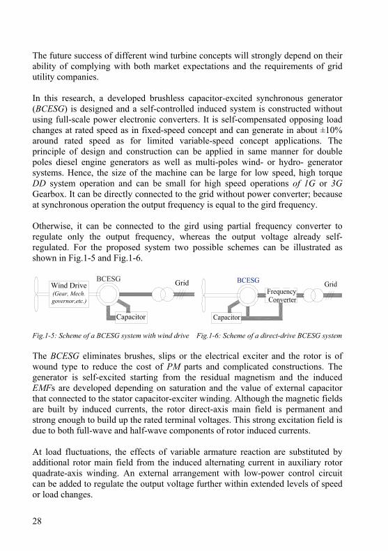
The future success of different wind turbine concepts will strongly depend on their ability of complying with both market expectations and the requirements of grid utility companies. In this research, a developed brushless capacitor-excited synchronous generator (BCESG) is designed and a self-controlled induced system is constructed without using full-scale power electronic converters. It is self-compensated opposing load changes at rated speed as in fixed-speed concept and can generate in about ±10% around rated speed as for limited variable-speed concept applications. The principle of design and construction can be applied in same manner for double poles diesel engine generators as well as multi-poles wind- or hydro- generator systems. Hence, the size of the machine can be large for low speed, high torque DD system operation and can be small for high speed operations of 1G or 3G Gearbox. It can be directly connected to the grid without power converter; because at synchronous operation the output frequency is equal to the gird frequency. Otherwise, it can be connected to the gird using partial frequency converter to regulate only the output frequency, whereas the output voltage already self-regulated. For the proposed system two possible schemes can be illustrated as shown in Fig.1-5 and Fig.1-6.
Fig.1-5: Scheme of a BCESG system with wind drive Fig.1-6: Scheme of a direct-drive BCESG system The BCESG eliminates brushes, slips or the electrical exciter and the rotor is of wound type to reduce the cost of PM parts and complicated constructions. The generator is self-excited starting from the residual magnetism and the induced EMFs are developed depending on saturation and the value of external capacitor that connected to the stator capacitor-exciter winding. Although the magnetic fields are built by induced currents, the rotor direct-axis main field is permanent and strong enough to build up the rated terminal voltages. This strong excitation field is due to both full-wave and half-wave components of rotor induced currents. At load fluctuations, the effects of variable armature reaction are substituted by additional rotor main field from the induced alternating current in auxiliary rotor quadrate-axis winding. An external arrangement with low-power control circuit can be added to regulate the output voltage further within extended levels of speed or load changes.
29
1.2 Research objectives The main object is to develop and investigate a generator system that can solve the problems relating to fluctuations, power stability and cost. For this purpose a comprehensive study and research project is presented and implemented with specific objectives that can be summarized as follows: 1- Exploring the technical advantages and disadvantages of recent renewable
energy turbine systems and finding an acceptable solution with emphasis on wind generators.
2- Investigating the state of the art in several aspects of design ideas, constructions and principle of operation for different types of brushless synchronous generators.
3- Designing a practical robust developed model of brushless self-excited and self-regulated synchronous generator that energized without slip-rings D.C. power exciters or power-electronic converters.
4- Developing an analytical design procedure, parameters and performance calculations of the BCESG at load changes within the rated speed limit; and comparing with results of design calculations of conventional types of synchronous generators.
5- Applying steady-state, dynamic analysis and post processing by using FEM simulation; beside the comprehensive study of time response analysis and comparing between the results of electromagnetic models for the presented generator and the existence and previous models.
6- Further, performing self compensation and control at load fluctuations at over/ lower rotation levels around rated rotational speed limit, by further designing a low-power control circuit and capacitor arrangements that can be externally connected to the machine stator windings.
7- Manufacturing a general prototype machine of 10 kW, 6 poles to obtain multi possible connections, as single-, multi-phase and multi-poles; and, applying laboratory tests to investigate the correspondence of theoretical and practical measurements results. Moreover to compare the characteristics between the presented type of synchronous generator and both previous capacitor-exciter and salient-poles D.C.-exciter synchronous generator models.
1.3 Methodology The study has a combination of extensive literature review on renewable energy turbine systems, comprehensive comparison of design principle and performances of different models of BCESGs, analytical solution based on generalized machine
30
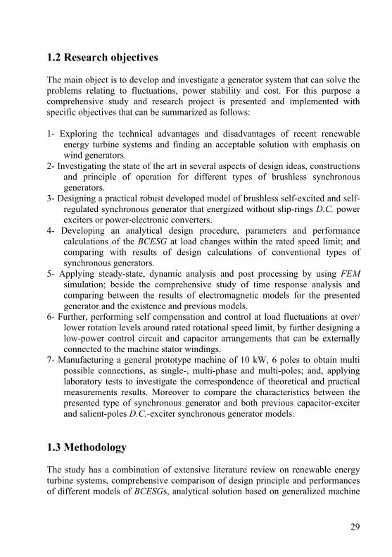
theory, FEM analysis and computer based simulation, design calculations/ CAD plots, general prototype, case studies and experimental investigation of resultant data. Whereas a general guidelines system for solving problems, with specific phases, tasks, methods, techniques and tools can be illustrated in the methodology diagram shown in Fig. 1-7.
BCESGFormulation
SystemProblems and
Models
DevelopedBCESGSolution
DifferentSimulationConditions
GeneralPrototypeSample
Different TestConditions/Comparison
ComputationalResults
Invisticationand
Improvements
GeneralizedMachine Theory
Based Design
NumericalFEM
Analysis
ExperimentalResults
Fig.1-7: The methodology diagram of the research work 1.4 Dissertation structure This research study and work presents theoretical, analytical and practical components which are structured in eight chapters, as described below. In chapter one, a wide overview of the problem back ground is presented and the proposed solution and objectives is described. It is included with an overview study of wind turbine generator systems. Chapter two focuses on the state of the art of BCESGs. Beside, a comprehensive study is presented and a comparison between other innovative designs is discussed. In chapter three, analytical formulations for the presented generator are derived,
31
based on generalized machine theory and primitive model. The comparison of analysis and characteristics between the first primary type, previous type and presented developed type of brushless capacitor-exciter alternators is illustrated. Windings design calculations, equivalent circuit steady-state parameters, magnetic circuit and saturation factor, performance computations and also the design procedure are devised in chapter four. The construction dimensions are calculated and engineering design diagrams are plotted by using CAD program. Moreover, the theoretical design data for a 10kW×1000r.p.m is compared with data-sheet results of similar size of salient-pole and non-salient poles three-phase synchronous generators, those are designed by applying ANSOFT-RMxprt software. In chapter five, FEM electromagnetic-simulation model is built by applying both ANSOFT-MAXELL and QUICKFIELD software. Thus to analysis and simulate the electromagnetic forces, beside the investigation of parameters, steady-state performance and transient response of the developed presented model of brushless generator. The comparison of simulation displays and time-response characteristics of developed model with that in previous model, salient and non-salient types of synchronous generators are intensively studied. Chapter six describes the practical construction dimensions, windings and external connections of the general prototype machine (10kW×1000 r.p.m); which is manually wound and assembled by the author, in the laboratories of the university (however, the new rotor lamination is manufacture by an industrial factory and the dimensions are modified by the mechanical work-shops). It is considerable to mention here that, the purpose of having externally extended coils-terminals for stator and rotor windings is to solve several problems in practical tests; those related to rotational-speed, poles, phases and load changes. Whence, by using the same prototype machine size, the experimental results of presented brushless generator are compared with the results of other machines types. Also the readings and displays for waveforms, harmonics, performance and other data of stator windings and rotor windings inside the machine, are easily plotted and experimentally investigated. In chapter seven, the complete generating system with additional electronic control circuit and external capacitors combination for further self-compensation at levels of rotational speed upper and lower than the rated speed limit is presented and described. The electronic circuit and wave forms are designed and simulated by using MULTISIM electronic components software. The discussion, conclusions and future overview for further development of brushless generating system against limited frequency changes are included in chapter eight.

32
33
Chapter 2
Brushless Synchronous Generating Systems
The knowledge of contact-less synchronous generators is well known since 1958 when an inventor used a short-circuited field winding with a diode to obtain self-excitation in a brushless generator [1]. It is shown that the structure of such synchronous generator is simple, robust and that the generators are highly reliable, easily maintained, and easily controlled [2]. For such advantages and the reasons study at previous chapter, a brushless synchronous self-excited and self-regulated generating system has been developed [3]. In this chapter, the construction, principle of operation and the state of art of developed generator is described, and comparisons with other previous innovative models are shown. 2.1 General structure of brushless capacitor-exciter synchronous
generator (BCESG) In this research work, a developed compound generating system is designed as shown in the general structure of Fig.2-1. It is self-excited and self-regulated for a standard output voltage limit within three levels of rotational speed variations and/or load changes. It comprises the BCESG that is compatible for two poles or multi-poles design. Beside, an external simple low-power electronic control (LPEC) circuit is further arranged with capacitors combination. A suitable capacitance value is auto-selected from a two capacitors combination at each new speed level by the effect of LPEC circuit, which may consider as a wind/ hydro fluctuation solver [4]. 2.1.1 Basic construction Basically the BCESG system is constructed of two main parts, the rotor assembly with rotating bridge rectifier of four diodes and the stator assembly with the external LPEC circuit and two capacitors combination, as detailed below. 2.1.1.1 Rotor assembly The rotor core designs in such a construction compound from salient & non-salient poles (SNSP) characteristics. The rotor stack is then assembly of electrical steel laminations of specific properties. An electrical phase shift of 60 or 90°E in space
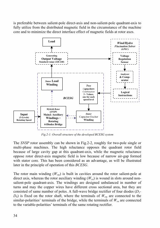
34
is preferable between salient-pole direct-axis and non-salient-pole quadrant-axis to fully utilize from the distributed magnetic field in the circumstance of the machine core and to minimize the direct interface effect of magnetic fields at rotor axes.
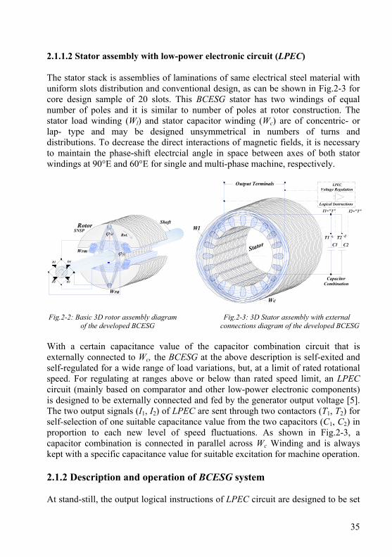
Fig.2-1: Overall structure of the developed BCESG system The SNSP rotor assembly can be shown in Fig.2-2, roughly for two-pole single or multi-phase machines. The high reluctance opposes the quadrant rotor field because of large cavity gap at this quadrant-axis, while the magnetic reluctance oppose rotor direct-axis magnetic field is low because of narrow air-gap formed with stator core. This has been considered as an advantage, as will be illustrated later in the principle of operation of this BCESG. The rotor main winding (Wrm) is built in cavities around the rotor salient-pole at direct axis, whereas the rotor auxiliary winding (Wra) is wound in slots around non-salient-pole quadrant-axis. The windings are designed unbalanced in number of turns and may the copper wires have different cross sectional area, but they are consisted of same number of poles. A full-wave bridge rectifier of four diodes (D1-D4) is fixed on the rotor shaft, where the terminals of Wrm are connected to the similar-polarities’ terminals of the bridge, while the terminals of Wra are connected to the variable-polarities’ terminals of the same rotating rectifier.
Input (3-Levels)
Rotating Speed
Load
Generating Output Voltage
Standard range (220-240)
Voltage Regulation
Sensor
Hybrid Rotor (SNSP)
Main& Auxiliary Windings +
Rotating 4-Diodes Bridge
Stator Load Winding
Analyzer & Comp-
arator
Logical Instructions
Two Capacitors Combination 3 - Values,
one for each speed level
Stator Capacitor Exciter
Winding
Wind/Hydro Fluctuation Solver
(LPEC)
BCESG
35
2.1.1.2 Stator assembly with low-power electronic circuit (LPEC) The stator stack is assemblies of laminations of same electrical steel material with uniform slots distribution and conventional design, as can be shown in Fig.2-3 for core design sample of 20 slots. This BCESG stator has two windings of equal number of poles and it is similar to number of poles at rotor construction. The stator load winding (Wl) and stator capacitor winding (Wc) are of concentric- or lap- type and may be designed unsymmetrical in numbers of turns and distributions. To decrease the direct interactions of magnetic fields, it is necessary to maintain the phase-shift electrcial angle in space between axes of both stator windings at 90°E and 60°E for single and multi-phase machine, respectively.
SNSPRotor
Wrm
Wra
D1
D2 D3
D4
Shaft
Rot.Wl
Wc
Voltage Regulation
Logical Instructions
LPEC
Stator
Output Terminals
I1="1" I2="1"
C1 C2T2T1
CapacitorCombination
ϕ fd
ϕ fq
Fig.2-2: Basic 3D rotor assembly diagram Fig.2-3: 3D Stator assembly with external of the developed BCESG connections diagram of the developed BCESG With a certain capacitance value of the capacitor combination circuit that is externally connected to Wc, the BCESG at the above description is self-exited and self-regulated for a wide range of load variations, but, at a limit of rated rotational speed. For regulating at ranges above or below than rated speed limit, an LPEC circuit (mainly based on comparator and other low-power electronic components) is designed to be externally connected and fed by the generator output voltage [5]. The two output signals (I1, I2) of LPEC are sent through two contactors (T1, T2) for self-selection of one suitable capacitance value from the two capacitors (C1, C2) in proportion to each new level of speed fluctuations. As shown in Fig.2-3, a capacitor combination is connected in parallel across Wc Winding and is always kept with a specific capacitance value for suitable excitation for machine operation. 2.1.2 Description and operation of BCESG system At stand-still, the output logical instructions of LPEC circuit are designed to be set
36
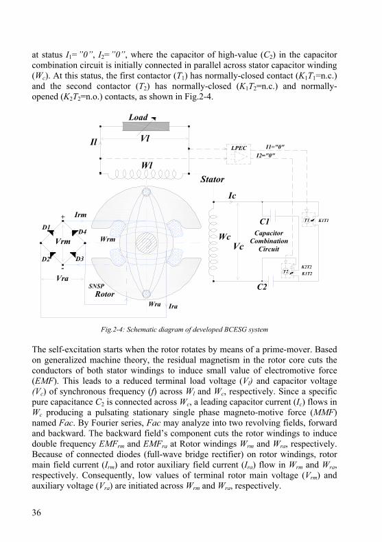
at status I1=”0”, I2=”0”, where the capacitor of high-value (C2) in the capacitor combination circuit is initially connected in parallel across stator capacitor winding (Wc). At this status, the first contactor (T1) has normally-closed contact (K1T1=n.c.) and the second contactor (T2) has normally-closed (K1T2=n.c.) and normally-opened (K2T2=n.o.) contacts, as shown in Fig.2-4.
SNSPRotor
Wrm
Wra
D1
D2 D3
D4
StatorWl
Wc
Load
Il
Irm
Ira
Ic
Vl
+
-
LPEC
C1
I1="0"I2="0"
K1T1T1
CapacitorCombination
CircuitVc
C2
T2
Vrm
VraK2T2K1T2
Fig.2-4: Schematic diagram of developed BCESG system The self-excitation starts when the rotor rotates by means of a prime-mover. Based on generalized machine theory, the residual magnetism in the rotor core cuts the conductors of both stator windings to induce small value of electromotive force (EMF). This leads to a reduced terminal load voltage (Vl) and capacitor voltage (Vc) of synchronous frequency (f) across Wl and Wc, respectively. Since a specific pure capacitance C2 is connected across Wc, a leading capacitor current (Ic) flows in Wc producing a pulsating stationary single phase magneto-motive force (MMF) named Fac. By Fourier series, Fac may analyze into two revolving fields, forward and backward. The backward field’s component cuts the rotor windings to induce double frequency EMFrm and EMFra at Rotor windings Wrm and Wra, respectively. Because of connected diodes (full-wave bridge rectifier) on rotor windings, rotor main field current (Irm) and rotor auxiliary field current (Ira) flow in Wrm and Wra, respectively. Consequently, low values of terminal rotor main voltage (Vrm) and auxiliary voltage (Vra) are initiated across Wrm and Wra, respectively.
37
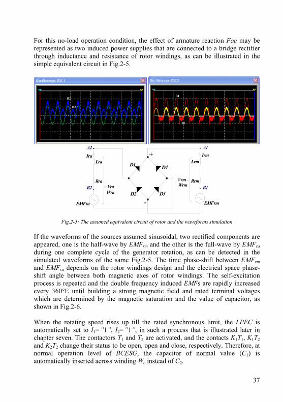
For this no-load operation condition, the effect of armature reaction Fac may be represented as two induced power supplies that are connected to a bridge rectifier through inductance and resistance of rotor windings, as can be illustrated in the simple equivalent circuit in Fig.2-5.
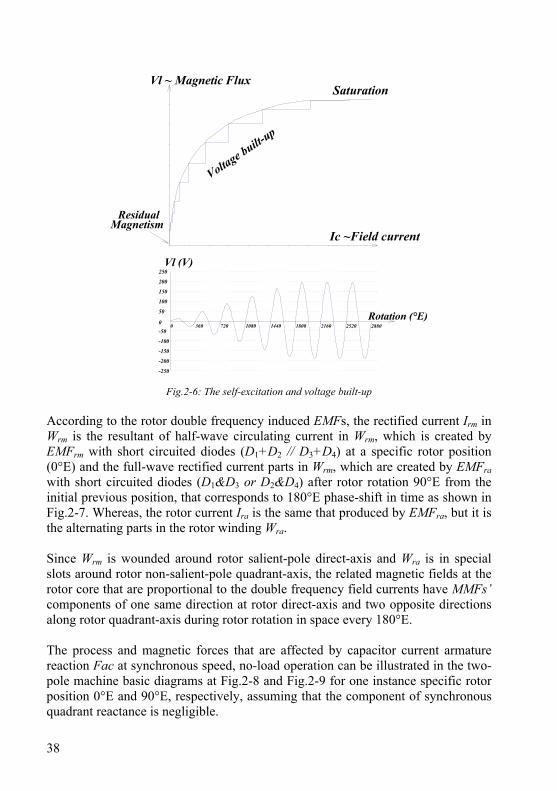
Fig.2-5: The assumed equivalent circuit of rotor and the waveforms simulation If the waveforms of the sources assumed sinusoidal, two rectified components are appeared, one is the half-wave by EMFrm and the other is the full-wave by EMFra during one complete cycle of the generator rotation, as can be detected in the simulated waveforms of the same Fig.2-5. The time phase-shift between EMFrm and EMFra depends on the rotor windings design and the electrical space phase-shift angle between both magnetic axes of rotor windings. The self-excitation process is repeated and the double frequency induced EMFs are rapidly increased every 360°E until building a strong magnetic field and rated terminal voltages which are determined by the magnetic saturation and the value of capacitor, as shown in Fig.2-6. When the rotating speed rises up till the rated synchronous limit, the LPEC is automatically set to I1=”1”, I2=”1”, in such a process that is illustrated later in chapter seven. The contactors T1 and T2 are activated, and the contacts K1T1, K1T2 and K2T2 change their status to be open, open and close, respectively. Therefore, at normal operation level of BCESG, the capacitor of normal value (C1) is automatically inserted across winding Wc instead of C2.
Ira Irm
WrmWra
EMFra
Lra
Rra
EMFrm
VraVrm
Lrm
Rrm
D1
D2 D3
D4
+
-
A1
B1
A2
B2
B2
B1
B2
B1
38
Ic ~Field current
Vl ~ Magnetic FluxSaturation
Voltage built-u
p
ResidualMagnetism
0
50
100
150
200
250
-50
-100
-150
-200
-250
0 360 720 1080 1440 1800 2160 2520 2880Rotation (°E)
Vl (V)
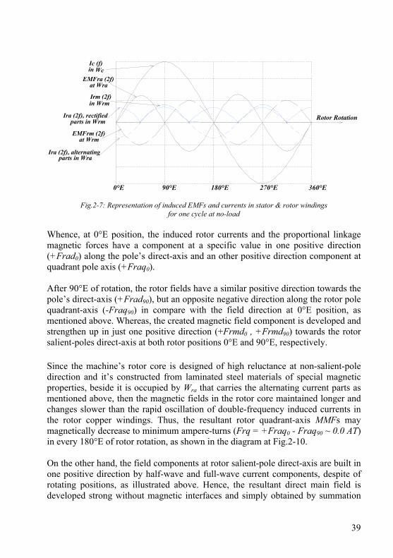
Fig.2-6: The self-excitation and voltage built-up According to the rotor double frequency induced EMFs, the rectified current Irm in Wrm is the resultant of half-wave circulating current in Wrm, which is created by EMFrm with short circuited diodes (D1+D2 // D3+D4) at a specific rotor position (0°E) and the full-wave rectified current parts in Wrm, which are created by EMFra with short circuited diodes (D1&D3 or D2&D4) after rotor rotation 90°E from the initial previous position, that corresponds to 180°E phase-shift in time as shown in Fig.2-7. Whereas, the rotor current Ira is the same that produced by EMFra, but it is the alternating parts in the rotor winding Wra. Since Wrm is wounded around rotor salient-pole direct-axis and Wra is in special slots around rotor non-salient-pole quadrant-axis, the related magnetic fields at the rotor core that are proportional to the double frequency field currents have MMFs’ components of one same direction at rotor direct-axis and two opposite directions along rotor quadrant-axis during rotor rotation in space every 180°E. The process and magnetic forces that are affected by capacitor current armature reaction Fac at synchronous speed, no-load operation can be illustrated in the two-pole machine basic diagrams at Fig.2-8 and Fig.2-9 for one instance specific rotor position 0°E and 90°E, respectively, assuming that the component of synchronous quadrant reactance is negligible.
39
at Wra
in Wrm
parts in WraIra (2f), alternating
Irm (2f)
EMFra (2f)in WcIc (f)
parts in WrmIra (2f), rectified
0°E 90°E 180°E 270°E 360°E
Rotor Rotation
at WrmEMFrm (2f)
Fig.2-7: Representation of induced EMFs and currents in stator & rotor windings
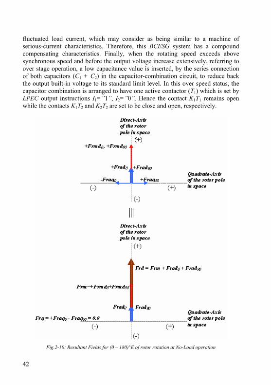
for one cycle at no-load Whence, at 0°E position, the induced rotor currents and the proportional linkage magnetic forces have a component at a specific value in one positive direction (+Frad0) along the pole’s direct-axis and an other positive direction component at quadrant pole axis (+Fraq0). After 90°E of rotation, the rotor fields have a similar positive direction towards the pole’s direct-axis (+Frad90), but an opposite negative direction along the rotor pole quadrant-axis (-Fraq90) in compare with the field direction at 0°E position, as mentioned above. Whereas, the created magnetic field component is developed and strengthen up in just one positive direction (+Frmd0 , +Frmd90) towards the rotor salient-poles direct-axis at both rotor positions 0°E and 90°E, respectively. Since the machine’s rotor core is designed of high reluctance at non-salient-pole direction and it’s constructed from laminated steel materials of special magnetic properties, beside it is occupied by Wra that carries the alternating current parts as mentioned above, then the magnetic fields in the rotor core maintained longer and changes slower than the rapid oscillation of double-frequency induced currents in the rotor copper windings. Thus, the resultant rotor quadrant-axis MMFs may magnetically decrease to minimum ampere-turns (Frq = +Fraq0 - Fraq90 ~ 0.0 AT) in every 180°E of rotor rotation, as shown in the diagram at Fig.2-10. On the other hand, the field components at rotor salient-pole direct-axis are built in one positive direction by half-wave and full-wave current components, despite of rotating positions, as illustrated above. Hence, the resultant direct main field is developed strong without magnetic interfaces and simply obtained by summation
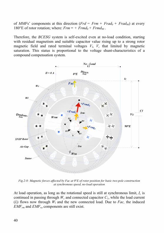
40
of MMFs’ components at this direction (Frd = Frm + Frad0 + Frad90) at every 180°E of rotor rotation; where: Frm = + Frmd0 + Frmd90 . Therefore, the BCESG system is self-excited even at no-load condition, starting with residual magnetism and suitable capacitor value rising up to a strong rotor magnetic field and rated terminal voltages Vl, Vc that limited by magnetic saturation. This status is proportional to the voltage shunt-characteristics of a compound compensation system.
SNSP Rotor
Wrm
Wra
Irm
Ira
D1
D2D3
D4
-
+
Stator
Air-Gap
Wl
Wc
Ic
Vc
+Frmd
Fac
C1
No - LoadVl
Il = 0 A 0°E
90°E
Direct-
Quadrate-
Axis
Axis
0+Frad
+Fraq0
0
Fig.2-8: Magnetic forces affected by Fac at 0°E of rotor position for basic two-pole construction at synchronous speed, no-load operation
At load operation, as long as the rotational speed is still at synchronous limit, Ic is continued in passing through Wc and connected capacitor C1, while the load current (Il) flows now through Wl and the new connected load. Due to Fac, the induced EMFrm and EMFra components are still exist.

41
Beside above, load armature reaction field (Fal) appears now and it is proportional to Il. If Fal waveform is pulsating, then it may resolved into two revolving field components, in the same manner mentioned above. The new backward field component induces additional two double-frequency induced EMF components in the rotor windings. This leads to new half-wave and full-wave rectified current components that flow in the rotor windings and produce additional MMFs. Therefore, despite of the demagnetizing effect of armature reaction, the additional MMF components may strengthen back the resultant rotor main magnetic field along rotor core direct-axis and compensate any decrease of main magnetic field.
SNSP Rotor
Wrm
Ira
D1D2
D3D4
-
+
Stator
Air-Gap
Wl
Wc
+Frmd
Fac
No - LoadVl
Il = 0 A 0°E
90°E
Direct-
Quadrate-
Axis
Axis
Wra
Ic
VcC1
+Frad90
-Fraq90
90
Fig.2-9: Magnetic forces affected by Fac at 90°E of rotor position for basic two-pole construction
at synchronous speed, no-load operation Moreover and as in the no-load condition, the resultant opposite direction fields at rotor core, quadrant-axis is also reduced to zero, because of high reluctance at non-salient-pole construction. The compensated rotor field is proportional to the
42
fluctuated load current, which may consider as being similar to a machine of serious-current characteristics. Therefore, this BCESG system has a compound compensating characteristics. Finally, when the rotating speed exceeds above synchronous speed and before the output voltage increase extensively, referring to over stage operation, a low capacitance value is inserted, by the series connection of both capacitors (C1 + C2) in the capacitor-combination circuit, to reduce back the output built-in voltage to its standard limit level. In this over speed status, the capacitor combination is arranged to have one active contactor (T1) which is set by LPEC output instructions I1=”1”, I2=”0”. Hence the contact K1T1 remains open while the contacts K1T2 and K2T2 are set to be close and open, respectively.
Fig.2-10: Resultant Fields for (0 – 180)°E of rotor rotation at No-Load operation
43
2.2 The state of the art and comparison with other operation concepts
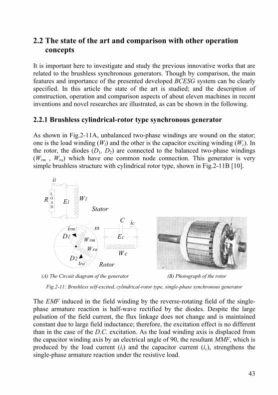
It is important here to investigate and study the previous innovative works that are related to the brushless synchronous generators. Though by comparison, the main features and importance of the presented developed BCESG system can be clearly specified. In this article the state of the art is studied; and the description of construction, operation and comparison aspects of about eleven machines in recent inventions and novel researches are illustrated, as can be shown in the following. 2.2.1 Brushless cylindrical-rotor type synchronous generator As shown in Fig.2-11A, unbalanced two-phase windings are wound on the stator; one is the load winding (Wl) and the other is the capacitor exciting winding (Wc). In the rotor, the diodes (D1, D2) are connected to the balanced two-phase windings (Wrm , Wra) which have one common node connection. This generator is very simple brushless structure with cylindrical rotor type, shown in Fig.2-11B [10].
W c
C ic
EcD1
D2
irm
W rm
Rotor
Stator
l
LOAD
W lEl
ω
ira
W ra
R
(A) The Circuit diagram of the generator (B) Photograph of the rotor
Fig.2-11: Brushless self-excited, cylindrical-rotor type, single-phase synchronous generator The EMF induced in the field winding by the reverse-rotating field of the single-phase armature reaction is half-wave rectified by the diodes. Despite the large pulsation of the field current, the flux linkage does not change and is maintained constant due to large field inductance; therefore, the excitation effect is no different than in the case of the D.C. excitation. As the load winding axis is displaced from the capacitor winding axis by an electrical angle of 90, the resultant MMF, which is produced by the load current (il) and the capacitor current (ic), strengthens the single-phase armature reaction under the resistive load.

44
The field currents (irm, ira) contain not only the shunt characteristic component that is proportional to ic, but also the series characteristic component, which is proportional to il. Therefore, the generator is of compound characteristic, and the voltage regulation can be reduced to zero by connecting a suitable capacitance to the capacitor winding (Wc). Similar to the developed BCESG of the research subject, this generator has no automatic voltage regulation and is maintenance-free. However, the magnetic field in the developed BCESG is much stronger because it is developed from both half-wave and full-wave components of the induced rotor currents. Beside, the unique rotor SNSP structure minimizes the linkage magnetic fields interfacing or distortion to the main rotor field, as mentioned above. 2.2.2 Synchronous generator with arrangement for brushless excitation An arrangement for three-phase brushless excitation synchronous machine is invented in 1977 [11]. The arrangement of windings is clear in Fig.2-12. The synchronous generator is designed in two suggestions. The first is as one assembly synchronous generator with an A.C. induction modifier (ACIM) with one longer shaft, but separated parts stator packet and separated parts rotor packet, where the rotor of the synchronous generator is salient-pole type.
Stator WindingAC Modifier
C
Stator Windingof Synchronous
Generator
3-Ph RotorWinding
RotorExciter
WindingShort-Circuit
Rotor
3-PhAsynchronousDrive Motor
V
ElectronicRegulator
Fig.2-12: Synchronous generator system with arrangement for brushless excitation The construction in the second suggestion is different in that the stator winding of the ACIM and the stator winding of the synchronous generator are all in one general stator packet. Also, the three-phase rotor winding of the ACIM and the excitation winding of synchronous generator are arranged on one general rotor packet, in a way, that the rotor packet is more like a cylindrical rotor construction.

45
Beside the above complicated arrangement, the ACIM stator windings consist of main phase, auxiliary-phase and capacitor (C), as shown in the above Fig.2-12. They connect to the stator winding of synchronous generator through an electronic regulator. Without this regulator circuit, the machine system cannot be excited or regulated. While the developed BCESG is constructed of one stator capacitor winding in addition to the load winding and it is self-excited and self-regulated at a specific speed limit, by using at least one initially connected capacitor that brings the generator into resonance status, without the need of additional control circuit. Therefore, it is considered that the presented developed BCESG is simpler in construction and has in compare higher efficiency. 2.2.3 Capacitor-excitation variable-resistor brushless synchronous
generator To enable an arbitrary adjustment of the output voltage with respect to the change in the load and the rotating speed, a capacitor- excitation type self-exciting synchronous generator is invented [12], thereof by connecting a capacitor and a variable resistor in series with a capacitor-exciting winding and forming a closed circuit therewith. When the rotor, shown in Fig.2-13, is rotated, initial amount of leading current (Ic) will flow in the capacitor-excitation winding; because the conductors of the winding are initially cut-in by residual magnetism at rotor core. Ic will gradually increase due to repeating of this self-excitation process at each rotating cycle. Hence, the induced EMF, Ec rises up until a considerable terminal voltage is established.
Load Ea LoadWinding
CVariable
Resistance
IcEcRotor
FieldWinding
IfDiode
Capacitor-ExcitationWinding
Ic
Stator
Fig.2-13: Capacitor-excitation variable-resistor type brushless synchronous generator At this time, an output voltage (Ea) is induced in the load winding. The variable resistance is set at zero until a rated voltage is established, thereby accelerating the
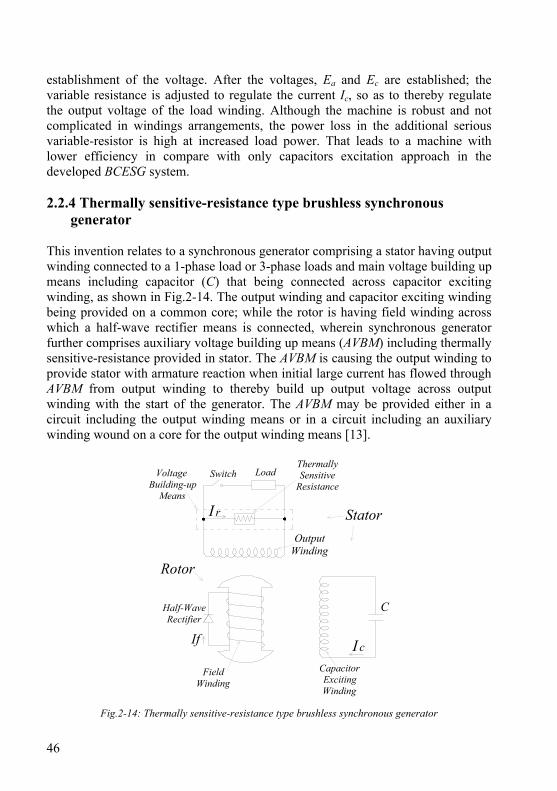
46
establishment of the voltage. After the voltages, Ea and Ec are established; the variable resistance is adjusted to regulate the current Ic, so as to thereby regulate the output voltage of the load winding. Although the machine is robust and not complicated in windings arrangements, the power loss in the additional serious variable-resistor is high at increased load power. That leads to a machine with lower efficiency in compare with only capacitors excitation approach in the developed BCESG system. 2.2.4 Thermally sensitive-resistance type brushless synchronous
generator This invention relates to a synchronous generator comprising a stator having output winding connected to a 1-phase load or 3-phase loads and main voltage building up means including capacitor (C) that being connected across capacitor exciting winding, as shown in Fig.2-14. The output winding and capacitor exciting winding being provided on a common core; while the rotor is having field winding across which a half-wave rectifier means is connected, wherein synchronous generator further comprises auxiliary voltage building up means (AVBM) including thermally sensitive-resistance provided in stator. The AVBM is causing the output winding to provide stator with armature reaction when initial large current has flowed through AVBM from output winding to thereby build up output voltage across output winding with the start of the generator. The AVBM may be provided either in a circuit including the output winding means or in a circuit including an auxiliary winding wound on a core for the output winding means [13].
C
FieldWinding
If I c
StatorOutput
Winding
LoadSwitchThermallySensitive
ResistanceVoltage
Building-upMeans
CapacitorExcitingWinding
I r
Half-WaveRectifier
Rotor
Fig.2-14: Thermally sensitive-resistance type brushless synchronous generator
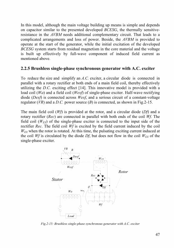
47
In this model, although the main voltage building up means is simple and depends on capacitor similar to the presented developed BCESG, the thermally sensitive-resistance in the AVBM needs additional complementary circuit. That leads to a complicated arrangements and loss of power. Beside, the AVBM is provided to operate at the start of the generator, while the initial excitation of the developed BCESG system starts from residual magnetism in the core material and the voltage is built up effectively by full-wave component of induced field current as mentioned above. 2.2.5 Brushless single-phase synchronous generator with A.C. exciter To reduce the size and simplify an A.C. exciter, a circular diode is connected in parallel with a rotary rectifier at both ends of a main field coil, thereby effectively utilizing the D.C. exciting effect [14]. This innovative model is provided with a load coil (Wa) and a field coil (Wexf) of single-phase exciter. Half-wave rectifying diode (Dexf) is connected across Wexf, and a serious circuit of a constant-voltage regulator (VR) and a D.C. power source (B) is connected, as shown in Fig.2-15. The main field coil (Wf) is provided at the rotor, and a circular diode (Df) and a rotary rectifier (Rec) are connected in parallel with both ends of the coil Wf. The field coil (WEX) of the single-phase exciter is connected to the input side of the rectifier Rec. The field coil Wf is excited by the field current induced by the coil WEX when the rotor is rotated. At this time, the pulsating exciting current induced at the coil Wf is circulated by the diode Df, but does not flow in the coil WEX of the single-phase exciter.
Wa
Load
wm
if
Wf
W EX
Rec
Df
Wexf
Dexf
BVR
Rotor
Stator
Fig.2-15: Brushless single-phase synchronous generator with A.C. exciter
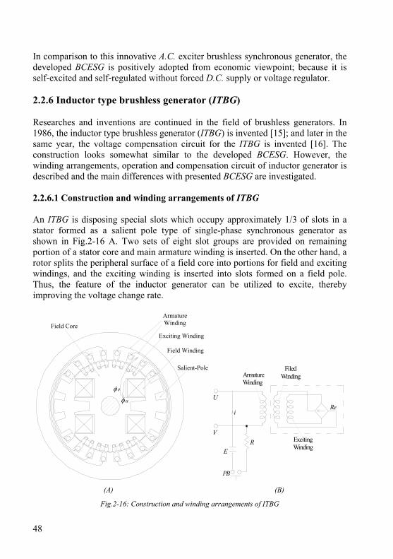
48
In comparison to this innovative A.C. exciter brushless synchronous generator, the developed BCESG is positively adopted from economic viewpoint; because it is self-excited and self-regulated without forced D.C. supply or voltage regulator. 2.2.6 Inductor type brushless generator (ITBG) Researches and inventions are continued in the field of brushless generators. In 1986, the inductor type brushless generator (ITBG) is invented [15]; and later in the same year, the voltage compensation circuit for the ITBG is invented [16]. The construction looks somewhat similar to the developed BCESG. However, the winding arrangements, operation and compensation circuit of inductor generator is described and the main differences with presented BCESG are investigated. 2.2.6.1 Construction and winding arrangements of ITBG An ITBG is disposing special slots which occupy approximately 1/3 of slots in a stator formed as a salient pole type of single-phase synchronous generator as shown in Fig.2-16 A. Two sets of eight slot groups are provided on remaining portion of a stator core and main armature winding is inserted. On the other hand, a rotor splits the peripheral surface of a field core into portions for field and exciting windings, and the exciting winding is inserted into slots formed on a field pole. Thus, the feature of the inductor generator can be utilized to excite, thereby improving the voltage change rate.
φ0
φα
ArmatureWinding
Field Winding
Salient-Pole
Field CoreExciting Winding
PB
E
V
U
i
ArmatureWinding
ExcitingWinding
Re
R
FiledWinding
(A) (B)
Fig.2-16: Construction and winding arrangements of ITBG
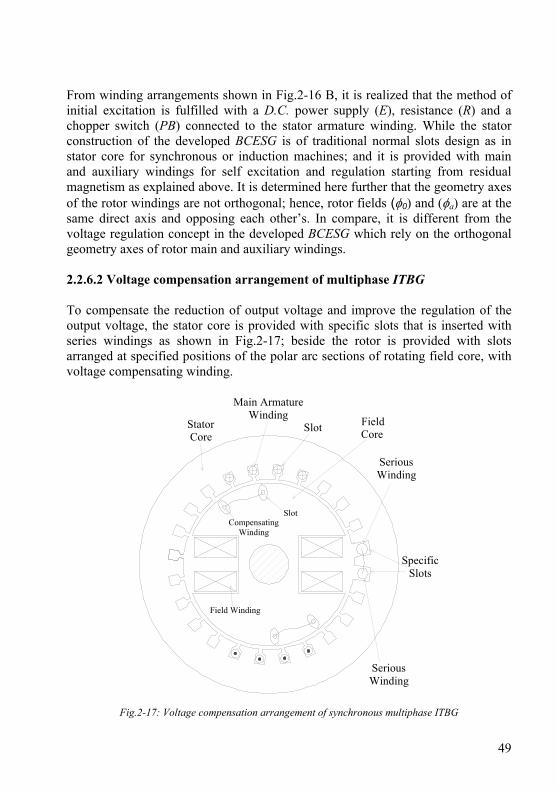
49
From winding arrangements shown in Fig.2-16 B, it is realized that the method of initial excitation is fulfilled with a D.C. power supply (E), resistance (R) and a chopper switch (PB) connected to the stator armature winding. While the stator construction of the developed BCESG is of traditional normal slots design as in stator core for synchronous or induction machines; and it is provided with main and auxiliary windings for self excitation and regulation starting from residual magnetism as explained above. It is determined here further that the geometry axes of the rotor windings are not orthogonal; hence, rotor fields (φ0) and (φa) are at the same direct axis and opposing each other’s. In compare, it is different from the voltage regulation concept in the developed BCESG which rely on the orthogonal geometry axes of rotor main and auxiliary windings. 2.2.6.2 Voltage compensation arrangement of multiphase ITBG To compensate the reduction of output voltage and improve the regulation of the output voltage, the stator core is provided with specific slots that is inserted with series windings as shown in Fig.2-17; beside the rotor is provided with slots arranged at specified positions of the polar arc sections of rotating field core, with voltage compensating winding.
FieldCore
CompensatingWinding
Slot
Field Winding
StatorCore
Slot
Main ArmatureWinding
SeriousWinding
SpecificSlots
SeriousWinding
Fig.2-17: Voltage compensation arrangement of synchronous multiphase ITBG
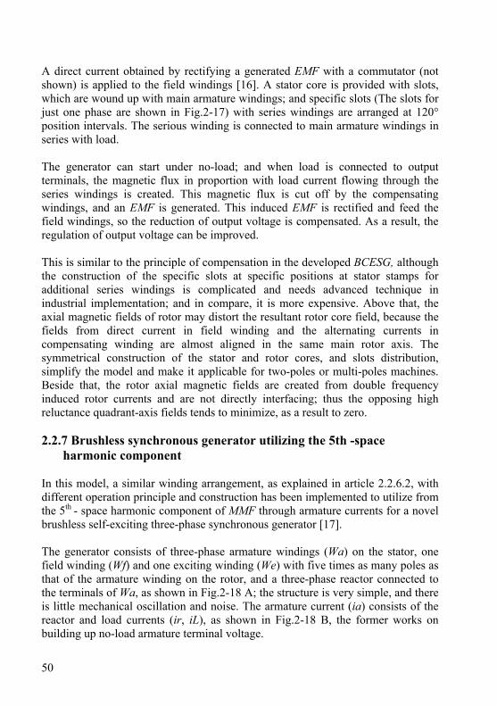
50
A direct current obtained by rectifying a generated EMF with a commutator (not shown) is applied to the field windings [16]. A stator core is provided with slots, which are wound up with main armature windings; and specific slots (The slots for just one phase are shown in Fig.2-17) with series windings are arranged at 120° position intervals. The serious winding is connected to main armature windings in series with load. The generator can start under no-load; and when load is connected to output terminals, the magnetic flux in proportion with load current flowing through the series windings is created. This magnetic flux is cut off by the compensating windings, and an EMF is generated. This induced EMF is rectified and feed the field windings, so the reduction of output voltage is compensated. As a result, the regulation of output voltage can be improved. This is similar to the principle of compensation in the developed BCESG, although the construction of the specific slots at specific positions at stator stamps for additional series windings is complicated and needs advanced technique in industrial implementation; and in compare, it is more expensive. Above that, the axial magnetic fields of rotor may distort the resultant rotor core field, because the fields from direct current in field winding and the alternating currents in compensating winding are almost aligned in the same main rotor axis. The symmetrical construction of the stator and rotor cores, and slots distribution, simplify the model and make it applicable for two-poles or multi-poles machines. Beside that, the rotor axial magnetic fields are created from double frequency induced rotor currents and are not directly interfacing; thus the opposing high reluctance quadrant-axis fields tends to minimize, as a result to zero. 2.2.7 Brushless synchronous generator utilizing the 5th -space
harmonic component In this model, a similar winding arrangement, as explained in article 2.2.6.2, with different operation principle and construction has been implemented to utilize from the 5th - space harmonic component of MMF through armature currents for a novel brushless self-exciting three-phase synchronous generator [17]. The generator consists of three-phase armature windings (Wa) on the stator, one field winding (Wf) and one exciting winding (We) with five times as many poles as that of the armature winding on the rotor, and a three-phase reactor connected to the terminals of Wa, as shown in Fig.2-18 A; the structure is very simple, and there is little mechanical oscillation and noise. The armature current (ia) consists of the reactor and load currents (ir, iL), as shown in Fig.2-18 B, the former works on building up no-load armature terminal voltage.
51
Rotor exciting winding WeArmature winding Wa
Field Winding Wf
Rotor
Stator
θ
Stator
Rotor
D
Wf
if
Wa
ia iL
Vabir
Reactor Xr
c
b
a
We
(A) (B)
Fig.2-18: Brushless synchronous generator utilizing the 5th - space harmonic component The induced voltage to the rotor exciting winding caused by the 5th-space harmonic component of MMF which in turn is caused by the armature currents is rectified and supplied to the field winding. As the ratio of the numbers of poles is an odd number, the generation of oscillatory tension due to the magnetic force between these poles is prevented. The advantages for small and medium machines are the small voltage regulation for various loads, low oscillation, low acoustic noise, robustness, easy operation, plus it is maintenance-free, and portable. Although, the bridge rectifier is used here as in the case for developed BCESG, the zero degree phase angle between the axes of rotor windings Wf and We leads to direct interfaces of axial magnetic fields which may distort the direct main rotor field as mentioned above, especially with the suggested cylindrical rotor construction. Beside that, the novel generator in this article has an unbalanced poles design in multiples of five, i.e. to obtain two-pole generator the rotor exciter winding is designed to have ten poles. Therefore, it is considerably difficult for multiple-pole application. 2.2.8 Brushless synchronous machine using amortisseur windings Polyphase amortisseur winding is used in a brushless self-excited synchronous generator of cylindrical rotor type not only to prevent appearance of upper-harmonic excitation currents as in squirrel-cage rotors, but also to generate the required magnitude of field current when connected to the field winding through Graetz rectifier [18].

52
As shown in Fig.2-19 A, the synchronous-machine rotor is designed as a laminated cylindrical rotor (without squirrel-cage), characterized by having narrow slots in the broad teeth. The polyphase amortisseur (F1, F2, F3) are having same poles number as that of the field winding, and they are uniformly distributed along the rotor periphery, and also connected through a Graetz rectifier to the terminals (K1, K2) of the field winding, as shown in Fig.2-19 B. F1 and F2 commonly with the field winding being accommodated in the wide slots outside the broad teeth, while the third phase (F3) being located in the narrow slots. This innovation is primarily for single-phase machines and the rotor construction is technically simple and interesting. The arrangement of rotor windings looks similar to the innovation discussed in article 2.2.2. However, the rotor constitute, windings and characteristics are different from rotor design features of the developed BCESG. Above that, the axial magnetic fields related to the alternating induced currents in the three-phase amortisseur windings may distort the main rotor direct axis magnetic field and increases the magnetic losses in the machine, where the reluctance is low at uniformly narrow air-gap around the peripheral of cylindrical rotor. Moreover, the power losses is considerable in three phase auxiliary winding in compare with the single phase auxiliary winding at the quadrant-axis of the rotor, that illustrated above in the construction of the presented developed BCESG.
NarrowSlots
BroadTeeth
NarrowSlots
BroadTeeth
WideSlots
WideSlots
Stator
U1
FieldWinding
PolyphaseAmortisseur
F3 F1
F2
CapacitorSplit-Phase
Winding
Stator
Load
GraetzRectifier
K1
K2
Main-Phase Winding
(A) (B)
Fig.2-19: Brushless synchronous-machine rotor and winding arrangements using amortisseur windings 2.2.9 Brushless cylindrical-rotor synchronous generator In recent researches, several schemes of four-pole brushless cylindrical-rotor three-phase synchronous generator are presented [19]. In original scheme, the stator is
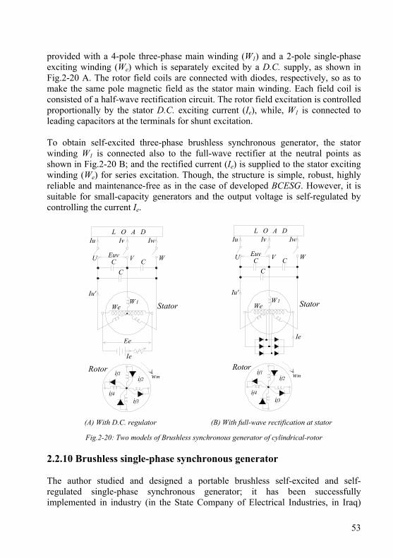
53
provided with a 4-pole three-phase main winding (W1) and a 2-pole single-phase exciting winding (We) which is separately excited by a D.C. supply, as shown in Fig.2-20 A. The rotor field coils are connected with diodes, respectively, so as to make the same pole magnetic field as the stator main winding. Each field coil is consisted of a half-wave rectification circuit. The rotor field excitation is controlled proportionally by the stator D.C. exciting current (Ie), while, W1 is connected to leading capacitors at the terminals for shunt excitation. To obtain self-excited three-phase brushless synchronous generator, the stator winding W1 is connected also to the full-wave rectifier at the neutral points as shown in Fig.2-20 B; and the rectified current (Ie) is supplied to the stator exciting winding (We) for series excitation. Though, the structure is simple, robust, highly reliable and maintenance-free as in the case of developed BCESG. However, it is suitable for small-capacity generators and the output voltage is self-regulated by controlling the current Ie.
WCCC
VU Euv
Iu'
WeW 1
Iu Iv Iw
Ie
Ee
if1 wmif2
if3if4
L O A D
Stator
Rotor
WCCC
VU Euv
Iu'
WeW1
Iu Iv Iw
if1 wmif2
if3if4
L O A D
Ie
Stator
Rotor
(A) With D.C. regulator (B) With full-wave rectification at stator
Fig.2-20: Two models of Brushless synchronous generator of cylindrical-rotor 2.2.10 Brushless single-phase synchronous generator The author studied and designed a portable brushless self-excited and self-regulated single-phase synchronous generator; it has been successfully implemented in industry (in the State Company of Electrical Industries, in Iraq)
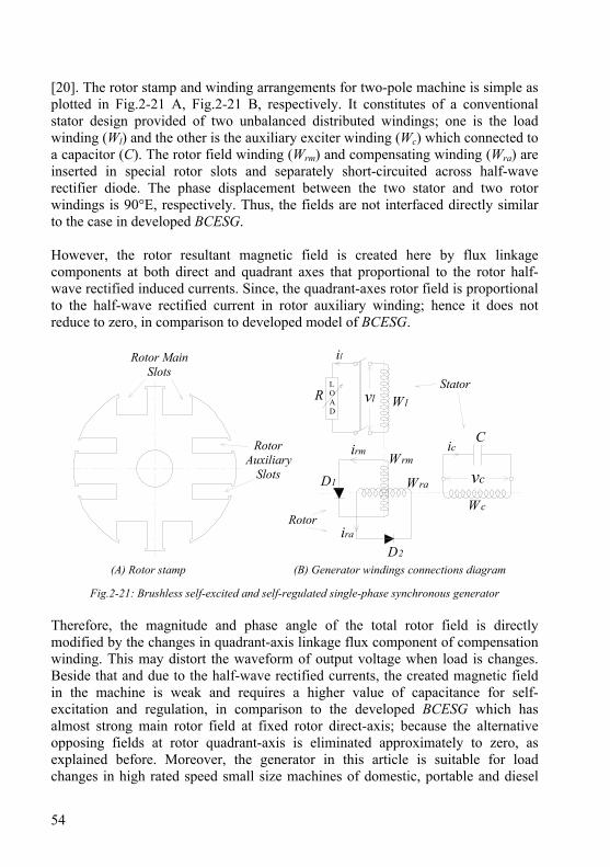
54
[20]. The rotor stamp and winding arrangements for two-pole machine is simple as plotted in Fig.2-21 A, Fig.2-21 B, respectively. It constitutes of a conventional stator design provided of two unbalanced distributed windings; one is the load winding (Wl) and the other is the auxiliary exciter winding (Wc) which connected to a capacitor (C). The rotor field winding (Wrm) and compensating winding (Wra) are inserted in special rotor slots and separately short-circuited across half-wave rectifier diode. The phase displacement between the two stator and two rotor windings is 90°E, respectively. Thus, the fields are not interfaced directly similar to the case in developed BCESG. However, the rotor resultant magnetic field is created here by flux linkage components at both direct and quadrant axes that proportional to the rotor half-wave rectified induced currents. Since, the quadrant-axes rotor field is proportional to the half-wave rectified current in rotor auxiliary winding; hence it does not reduce to zero, in comparison to developed model of BCESG.
irm
D1
ira
2
Wra
Wrm
C
Wc
vc
ic
l
vl Wl
LOAD
Rotor MainSlots
RotorAuxiliary
Slots
RStator
Rotor
(A) Rotor stamp (B) Generator windings connections diagram
Fig.2-21: Brushless self-excited and self-regulated single-phase synchronous generator Therefore, the magnitude and phase angle of the total rotor field is directly modified by the changes in quadrant-axis linkage flux component of compensation winding. This may distort the waveform of output voltage when load is changes. Beside that and due to the half-wave rectified currents, the created magnetic field in the machine is weak and requires a higher value of capacitance for self-excitation and regulation, in comparison to the developed BCESG which has almost strong main rotor field at fixed rotor direct-axis; because the alternative opposing fields at rotor quadrant-axis is eliminated approximately to zero, as explained before. Moreover, the generator in this article is suitable for load changes in high rated speed small size machines of domestic, portable and diesel
55
applications; while the generating system in the developed BCESG can be applied successfully in variable speed with load changes. 2.2.11 Brushless generator with a novel voltage regulator In 2007, an innovative arrangement and voltage regulator circuit is invented for brushless A.C. generator [21]. The voltage regulator unit is externally connected to regulate the output voltage of the generator. The circuit is fed by both output voltage (Vout) at armature winding and auxiliary voltage (Vaux) from the induced EMF at auxiliary winding, as shown in Fig.2-22 A. By the differences between Vout, Vaux and a reference voltage (Vrif), the controlled switch turns continuously on/off. As a response, the capacitor current Ic is controlled to regulate the output voltage. The synchronous generator in this invention is similar to the developed BCESG in having two windings at stator unit. However, it is constructed at rotor unit of one main rotor field winding 11 short circuited across half-wave rectifier 12, as in the brushless synchronous generator of capacitor-excitation variable-resistor type and the thermally sensitive-resistance type illustrated already in articles 2.2.3 and 2.2.4, respectively. The voltage regulator circuit is of power-electronic components, based mainly on an insulated-gate bipolar transistor (IGBT), shown in controlled switch, Fig.2-22 B.
VoutZ
Z2C2
C1
Ic
Vint
Vrif
VauxVout Control
Circuit
ControlledSwitch
12
ArmatureWinding
RotorUnit
StatorUnit
AuxiliaryWinding
11
14
ControlledSwitch
14
(A) The generator circuit with voltage regulator unit (B) The control switch in the regulator unit
Fig.2-22: Brushless capacitor-exciter type synchronous generator with voltage regulator The synchronous generator can not be self-regulated without the existence of the automatic voltage regulator, which is a part of the auxiliary winding, while the
56
developed BCESG is self-excited and self-regulated independently at rated-speed limit and considerable load changes. The LPEC circuit is mainly designed of operational amplifier and externally connected to increase the rotating-speed level of the generator operation above or lower than the rated rotational speed limit, as mentioned before. Moreover, LPEC is fed only by the output voltage at the stator load winding to give output control signals that affects on contactors connected in the stator auxiliary winding. 2.3 Main features of the presented developed BCESG Upon the comprehensive study mentioned above, the main features of the suggested BCESG, in compared with the recent innovations of brushless synchronous machines, can be abbreviated as the following: 1 - Although the magnetic forces are produced by induced currents, the rotor main magnetic field is built up strong; because it is created by full-wave and half-wave rectified components; hence the performance can be similar to that in a generator of permanent-magnetic poles. 2 - The resultant opposing-direction magnetic fields at quadrant-axis, high reluctance rotor part are reduced to minimum value, so by maintaining a suitable saturation, the core material can be reduced at these parts. This is considerable from economic viewpoint in comparison to standard size of induction or synchronous machines. 3 - The auxiliary rotor windings, which are inserted into special rotor slots at quadrant-axis, carry the AC component of rotor currents and have short circuit paths. However, beside the voltage compensation, the function of these windings is to damp the torsional oscillations in the rotor that may occur as a result of load fluctuations. Moreover, they may play a role in preventing rotor overheating when a synchronous machine is exposed to negative sequence currents in a subject of short-circuit case. 4 - The BCESG appears self-compound characteristics at rated speed and changeable load without additional control circuit, external connections or D.C. exciter means; for this purpose, the capacitor approach is used to reduce the power losses in compare to the variable resistors or inductors methods. Beside, the design concept is simple and may easily be applicable for double-pole, as well as multi poles machines.
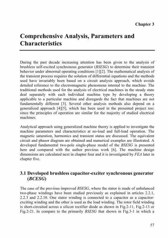
57
Chapter 3
Comprehensive Analysis, Parameters and Characteristics
During the past decade increasing attention has been given to the analysis of brushless self-excited synchronous generator (BSESG) to determine their transient behavior under abnormal operating conditions [1][2]. The mathematical analysis of the transient process requires the solution of differential equations and the methods used have invariably been based on a circuit analysis approach, which avoids detailed reference to the electromagnetic phenomena internal to the machine. The traditional methods used for the analysis of electrical machines in the steady state deal separately with each individual machine type by developing a theory applicable to a particular machine and disregards the fact that machines are not fundamentally different [3]. Several other analysis methods also depend on a generalized approach [4][5], which has been used in the presented project too; since the principles of operation are similar for the majority of studied electrical machines. Analytical approach using generalized machine theory is applied to investigate the machine parameters and characteristics at no-load and full-load operation. The magnetic saturation, harmonics and transient status are discussed. The equivalent circuit and phasor diagram are obtained and numerical examples are illustrated. A developed fundamental two-pole single-phase model of the BSESG is presented here and compared with the author previous work [6]. The machine design dimensions are calculated next in chapter four and it is investigated by FEA later in chapter five. 3.1 Developed brushless capacitor-exciter synchronous generator
(BCESG) The case of the previous improved BSESG, where the stator is made of unbalanced two-phase windings have been studied previously as explained in articles 2.2.1, 2.2.3 and 2.2.10. One stator winding is connected to a capacitor as a capacitor-exciting winding and the other is used as the load winding. The rotor field winding is short-circuited across a silicon rectifier diode as shown in Fig.2-11, Fig.2-13 or Fig.2-21. In compare to the primarily BSESG that shown in Fig.3-1 in which a
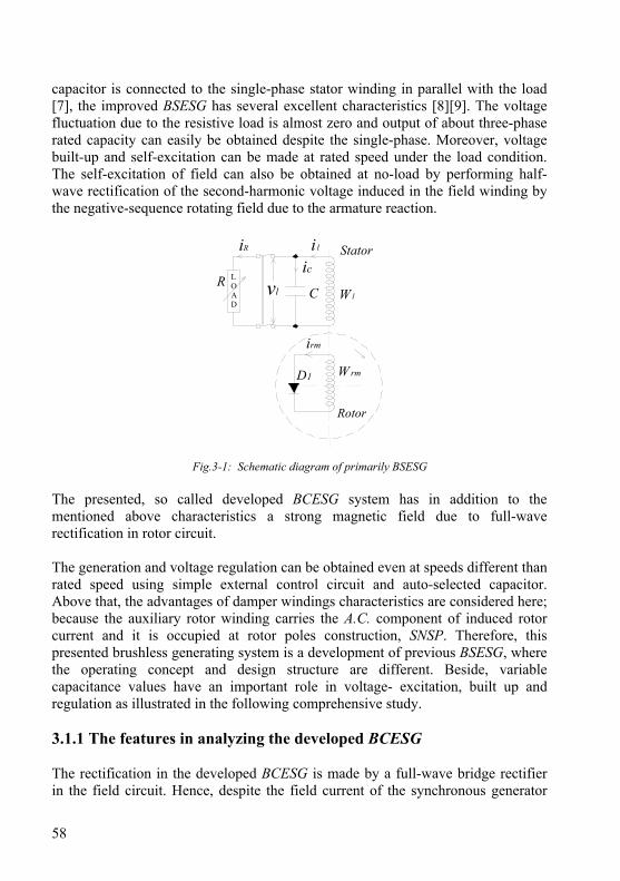
58
capacitor is connected to the single-phase stator winding in parallel with the load [7], the improved BSESG has several excellent characteristics [8][9]. The voltage fluctuation due to the resistive load is almost zero and output of about three-phase rated capacity can easily be obtained despite the single-phase. Moreover, voltage built-up and self-excitation can be made at rated speed under the load condition. The self-excitation of field can also be obtained at no-load by performing half-wave rectification of the second-harmonic voltage induced in the field winding by the negative-sequence rotating field due to the armature reaction.
irm
D1 W rm
iR
vl W l
LOAD
RC
ic
i l
Rotor
Stator
Fig.3-1: Schematic diagram of primarily BSESG The presented, so called developed BCESG system has in addition to the mentioned above characteristics a strong magnetic field due to full-wave rectification in rotor circuit. The generation and voltage regulation can be obtained even at speeds different than rated speed using simple external control circuit and auto-selected capacitor. Above that, the advantages of damper windings characteristics are considered here; because the auxiliary rotor winding carries the A.C. component of induced rotor current and it is occupied at rotor poles construction, SNSP. Therefore, this presented brushless generating system is a development of previous BSESG, where the operating concept and design structure are different. Beside, variable capacitance values have an important role in voltage- excitation, built up and regulation as illustrated in the following comprehensive study. 3.1.1 The features in analyzing the developed BCESG The rectification in the developed BCESG is made by a full-wave bridge rectifier in the field circuit. Hence, despite the field current of the synchronous generator
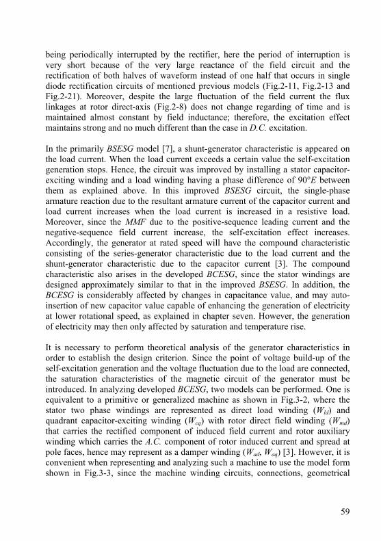
59
being periodically interrupted by the rectifier, here the period of interruption is very short because of the very large reactance of the field circuit and the rectification of both halves of waveform instead of one half that occurs in single diode rectification circuits of mentioned previous models (Fig.2-11, Fig.2-13 and Fig.2-21). Moreover, despite the large fluctuation of the field current the flux linkages at rotor direct-axis (Fig.2-8) does not change regarding of time and is maintained almost constant by field inductance; therefore, the excitation effect maintains strong and no much different than the case in D.C. excitation. In the primarily BSESG model [7], a shunt-generator characteristic is appeared on the load current. When the load current exceeds a certain value the self-excitation generation stops. Hence, the circuit was improved by installing a stator capacitor-exciting winding and a load winding having a phase difference of 90°E between them as explained above. In this improved BSESG circuit, the single-phase armature reaction due to the resultant armature current of the capacitor current and load current increases when the load current is increased in a resistive load. Moreover, since the MMF due to the positive-sequence leading current and the negative-sequence field current increase, the self-excitation effect increases. Accordingly, the generator at rated speed will have the compound characteristic consisting of the series-generator characteristic due to the load current and the shunt-generator characteristic due to the capacitor current [3]. The compound characteristic also arises in the developed BCESG, since the stator windings are designed approximately similar to that in the improved BSESG. In addition, the BCESG is considerably affected by changes in capacitance value, and may auto-insertion of new capacitor value capable of enhancing the generation of electricity at lower rotational speed, as explained in chapter seven. However, the generation of electricity may then only affected by saturation and temperature rise. It is necessary to perform theoretical analysis of the generator characteristics in order to establish the design criterion. Since the point of voltage build-up of the self-excitation generation and the voltage fluctuation due to the load are connected, the saturation characteristics of the magnetic circuit of the generator must be introduced. In analyzing developed BCESG, two models can be performed. One is equivalent to a primitive or generalized machine as shown in Fig.3-2, where the stator two phase windings are represented as direct load winding (Wld) and quadrant capacitor-exciting winding (Wcq) with rotor direct field winding (Wmd) that carries the rectified component of induced field current and rotor auxiliary winding which carries the A.C. component of rotor induced current and spread at pole faces, hence may represent as a damper winding (Wad, Waq) [3]. However, it is convenient when representing and analyzing such a machine to use the model form shown in Fig.3-3, since the machine winding circuits, connections, geometrical
60
positions and number of phases for basic two poles machine are clearly illustrated. Therefore, the model of Fig.3-3 is considered in this presented research project.
ω
Wcq
Waq
Wmd Wad Wld Directaxis
Quadratureaxis
Fig.3-2: The equivalent primitive circuit of BCESG
D1
D2
D4
D3
Wl
WcWrm
Load vl
C
Directaxis
Quadratureaxis
R
θ
ω = dθ /dt
St.
Rt.
il
vcic
ira
I rm
vraWra
Vrm
l
ϕ fq
ϕc
ϕ fd
Fig.3-3: Schematic diagram of BCESG for an instant at load operation

61
The analysis is first performed without considering the nonlinearity of the inductance, and the relative relation of the currents is determined. Then, the nonlinearity due to the saturation of the magnetic circuit for the inductance is introduced and the no-load and load characteristics of the generator are analyzed by approximate approach to determine the currents at balanced condition. The range of the capacitor for the generation is determined and the compound characteristics are theoretically derived. 3.1.2 The assumptions in analyzing the developed BCESG As shown in Fig.3-3, in the fundamental model of developed BCESG of two windings SNSP rotor type, a leading current (ic) will flow in the capacitor (C) and in the excitation winding (Wc) due to the induced voltage (vc) by the residual magnetism, and self-excitation phenomena will take place leading to an increased magnetization proportional to this ic . At the same time, the field negative-sequence induced EMF due to armature reaction is rectified by the full bridge rectifier diodes (D1, D2, D3, D4) that connected to the rotor main field winding (Wrm) through the rotor auxiliary winding (Wra). Hence the self-excitation of the generator’s magnetic field occurs. To simplify the analysis, the following assumptions are considered [10][11][12][13]: 1 - The rotor rotates at a constant angular velocity (ω). 2 - By an equivalent transformation, the stator windings (Wl and Wc) are considered
as a balanced two-phase windings, also the number of turns for each rotor winding is considered similar.
3 - Rotor and stator windings are designed to have a specific linkage flux and mutual inductances; hence, for an instance the induced EMF around Wra is higher than that around Wrm , then at this moment the rotor circuit is considered as a traditional full-wave bridge rectifier electrical circuit of four-diode. At an other instance (after 90 °E), the induced EMF across Wrm becomes higher than induced EMF across Wra . Thus the half-wave component of the induced current may circulate in Wrm through the four short-circuited diodes (D1 - D2 and D3 - D4) and the current through Wra is considered in compare very low and may neglected for this instant.
4 - The resistance of stator and rotor windings is sufficiently small compared to respective reactance.
5 - The effect of the space harmonics is neglected. That is, the MMF of the armature winding has a sinusoidal wave-shape and the winding coefficients for all harmonics are zero.
6 - The saturation of the magnetic circuit must not be neglected; it is an important factor in the determination of the voltage build-up of the self-excitation and the generation characteristics.
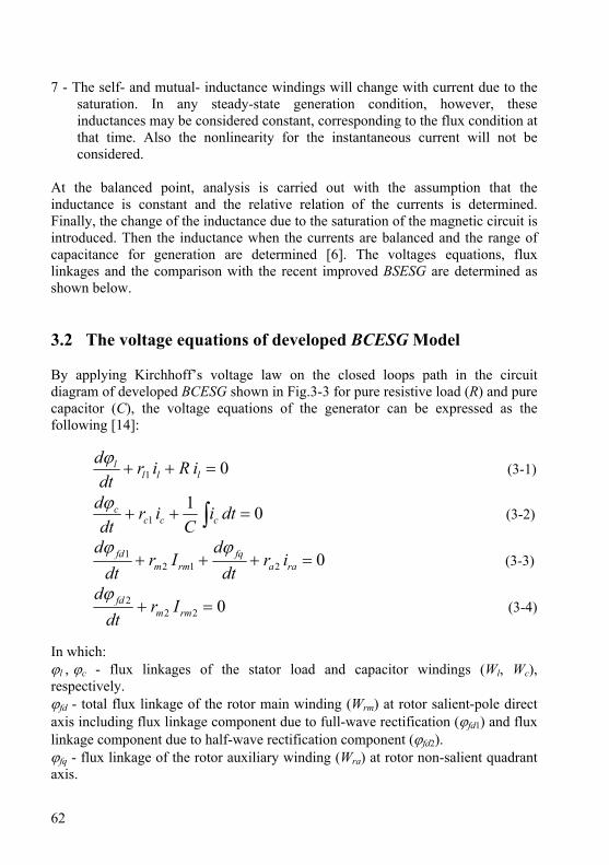
62
7 - The self- and mutual- inductance windings will change with current due to the saturation. In any steady-state generation condition, however, these inductances may be considered constant, corresponding to the flux condition at that time. Also the nonlinearity for the instantaneous current will not be considered.
At the balanced point, analysis is carried out with the assumption that the inductance is constant and the relative relation of the currents is determined. Finally, the change of the inductance due to the saturation of the magnetic circuit is introduced. Then the inductance when the currents are balanced and the range of capacitance for generation are determined [6]. The voltages equations, flux linkages and the comparison with the recent improved BSESG are determined as shown below. 3.2 The voltage equations of developed BCESG Model By applying Kirchhoff’s voltage law on the closed loops path in the circuit diagram of developed BCESG shown in Fig.3-3 for pure resistive load (R) and pure capacitor (C), the voltage equations of the generator can be expressed as the following [14]:
01 =++ llll iRir
dtdϕ
(3-1)
011 =++ ∫ dti
Cir
dtd
ccccϕ
(3-2)
02121 =+++ raa
fqrmm
fd irdt
dIr
dtd ϕϕ
(3-3)
0222 =+ rmm
fd Irdt
dϕ (3-4)
In which: ϕl , ϕc - flux linkages of the stator load and capacitor windings (Wl, Wc), respectively. ϕfd - total flux linkage of the rotor main winding (Wrm) at rotor salient-pole direct axis including flux linkage component due to full-wave rectification (ϕfd1) and flux linkage component due to half-wave rectification component (ϕfd2). ϕfq - flux linkage of the rotor auxiliary winding (Wra) at rotor non-salient quadrant axis.
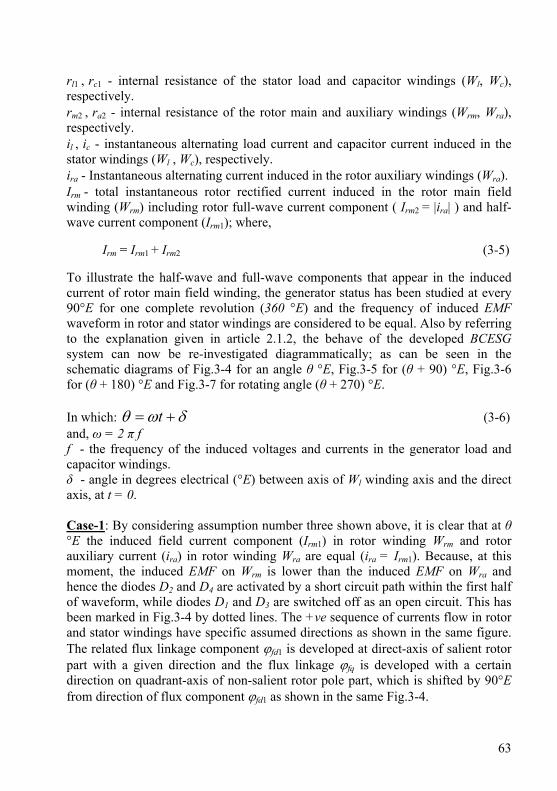
63
rl1 , rc1 - internal resistance of the stator load and capacitor windings (Wl, Wc), respectively. rm2 , ra2 - internal resistance of the rotor main and auxiliary windings (Wrm, Wra), respectively. il , ic - instantaneous alternating load current and capacitor current induced in the stator windings (Wl , Wc), respectively. ira - Instantaneous alternating current induced in the rotor auxiliary windings (Wra). Irm - total instantaneous rotor rectified current induced in the rotor main field winding (Wrm) including rotor full-wave current component ( Irm2 = |ira| ) and half-wave current component (Irm1); where,
Irm = Irm1 + Irm2 (3-5) To illustrate the half-wave and full-wave components that appear in the induced current of rotor main field winding, the generator status has been studied at every 90°E for one complete revolution (360 °E) and the frequency of induced EMF waveform in rotor and stator windings are considered to be equal. Also by referring to the explanation given in article 2.1.2, the behave of the developed BCESG system can now be re-investigated diagrammatically; as can be seen in the schematic diagrams of Fig.3-4 for an angle θ °E, Fig.3-5 for (θ + 90) °E, Fig.3-6 for (θ + 180) °E and Fig.3-7 for rotating angle (θ + 270) °E. In which: δωθ += t (3-6) and, ω = 2 π f f - the frequency of the induced voltages and currents in the generator load and capacitor windings. δ - angle in degrees electrical (°E) between axis of Wl winding axis and the direct axis, at t = 0. Case-1: By considering assumption number three shown above, it is clear that at θ °E the induced field current component (Irm1) in rotor winding Wrm and rotor auxiliary current (ira) in rotor winding Wra are equal (ira = Irm1). Because, at this moment, the induced EMF on Wrm is lower than the induced EMF on Wra and hence the diodes D2 and D4 are activated by a short circuit path within the first half of waveform, while diodes D1 and D3 are switched off as an open circuit. This has been marked in Fig.3-4 by dotted lines. The +ve sequence of currents flow in rotor and stator windings have specific assumed directions as shown in the same figure. The related flux linkage component ϕfd1 is developed at direct-axis of salient rotor part with a given direction and the flux linkage ϕfq is developed with a certain direction on quadrant-axis of non-salient rotor pole part, which is shifted by 90°E from direction of flux component ϕfd1 as shown in the same Fig.3-4.

64
D1
D2
D4
D3
ira
Cic
R
il
I rm1
Wrm
Wra
ωθ
Wc
Wl
ϕ fq
ϕ fd1
D1
D2
D4
D3
ira≈0I rm2
WrmWra
ω
θ +90°Ε
ϕ fq
ϕ fd2C
ic
R
il
Wc
Wl
Fig.3-4: Schematic diagram of BCESG Fig.3-5: Schematic diagram of BCESG at θ °E angle of rotation (Case-1) at (θ + 90) °E angle of rotation (Case-2) Case-2: After 90 °E of rotor rotation and by considering again assumption number three. The induced EMF on main rotor winding Wrm becomes higher than the induced EMF on Wra, hence the four diodes of the bridge rectifier are activated as short-circuited path across rotor main winding Wrm, which is shown by dark lines in Fig.3-5 above. All induced rotor current circulates through the winding Wrm and a very little current may pass in the winding Wra which in compare tends to be of zero value (ira ≈ 0 A). This new induced current component in winding Wrm is denoted as Irm2 which is different in value from the already existent current component Irm1. Irm2 flows in Wrm in the same +ve sequence direction of the induced current component Irm1, that illustrated previously in Case-1. Therefore, a new flux-linkage component (φfd2) is developed with a specific direction at the direct-axis of rotor salient-pole part as shown in Fig.3-5. This φfd2, in compare to Case-1 has similar direction to that for the previous flux-linkage component φfd1. In this case, the auxiliary rotor winding Wra is considered as an open circuit and the quadrate-axis flux-linkage (φfq) at rotor non-salient part tends to be very low. Hence in Fig.3-5, Wra is referred by a dotted line, the vector line of φfq appears shorter and the +ve sequence directions of induced currents in rotor and stator windings remains the same as in Fig.3-4 of the above case. Case-3: At the moment (θ + 180) °E which considered as the second half of waveform, the induced EMF on Wrm returns again lower than that on Wra . The diodes D2 and D4 turns off (open-circuit) and the other diodes D1 and D3 turns on (short-circuit). The rotor current flows in both series rotor windings Wrm and Wra as the status in Case-1 above. Hence, the induced current component in Wrm winding has the same value and +ve sequence direction similar to the current component

65
Irm1 of Case-1 above. Also then, the related flux component φfd1 remains in the same direction as in the cases shown above. More, the induced current in rotor auxiliary winding Wra has the same value of current ira that illustrated in Case-1. After 180 °E the polarity of induced EMF across Wra changes, then ira is alternating here to a -ve sequence direction in compare to its status at Case-1 and thus the related flux linkage φfq has also a reverse direction to its status in both cases above, as shown in Fig.3-6. Therefore, it can be detected here that: ira = - Irm1 . The direction of induced currents il and ic in the stator windings are also altered in this second half of waveform, hence they consider as an alternating current (A.C.). Case-4: After 270°E of rotor rotation, the induced EMF on main rotor winding Wrm becomes again higher than the induced EMF on Wra but with opposite polarity in compare to the status of Case-2. Therefore, the four diodes of the bridge rectifier may activate as an open circuit. This is marked by dotted lines as shown in Fig.3-7. Then at this moment, the induced rotor currents in both rotor windings tend to be very low near zero (ira ≈ 0 A and Irm2 ≈ 0 A).
D1
D2
D4
D3
ira
I rm1
Wrm
Wra
ωθ +
180°Ε
ϕ fq
ϕ fd1
Cic
R
il
Wc
Wl
D1
D2
D4
D3
ira≈0
I rm2≈0
WrmWra
ω
θ +270 °Ε
ϕ fq
ϕ fd2
Cic
R
il
Wc
Wl
Fig.3-6: schematic diagram of BCESG Fig.3-7: schematic diagram of BCESG at (θ + 180)°E angle of rotation (Case-3) at (θ + 270)°E angle of rotation(Case-4) It is noticed, from the both halves of waveform illustrated in Case-1 and Case-3, that the induced current ira in rotor winding Wra appears alternating (A.C.), while the induced current component Irm1 in rotor winding Wrm is kept in one direction as a direct current (D.C.). That means the rotor circuit through these cases behave as a full-wave rectified circuit and Irm1 may consider as a full-wave rectified current component. While, from the both halves of waveform illustrated in Case-2 and

66
Case-4 above, the induced current component Irm2 in rotor winding Wrm is kept in one direction as a direct current (D.C.). The induced current ira in rotor winding Wra (approximately open-circuit) minimizes to zero value (ira ≈ 0 A). Then Irm2 corresponds to a half-wave rectified current component passes through rotor main winding Wrm that short-circuited across four diodes group. Therefore, in each complete electrical cycle based on the above four cases, the plot of induced EMFs and currents waveform of rotor main and auxiliary windings can be clarified diagrammatically in Fig.3-8, whereas the half-wave and full-wave rectified current components and the A.C. component for the above cases study are well illustrated for two cycles. The resultant waveform (Irm) of induced rotor currents components in the rotor main winding Wrm can be interpreted as a full-wave rectification current component that is shifted by a specific pure D.C. level component shown in same Fig.3-8. This will be investigated experimentally for the prototype generator, later in chapter six.
(θ+90) °Ε(θ+180) °Ε
(θ+270) °Ε
θ °Ε
+ ve
- ve
Rotation inElectrical Cycles
1st half of Waveform 2nd half of Waveform
I rm2
I rm1
ira
EMFat Wra
I rm = (I rm1 + Irm2)I rm1
ira
I rm2EMF
at Wrm
EMFat Wra
1 2 3 4
Shifting byDC Level
Full-waverectification
+
Fig.3-8: Waveforms representation for the developed BCESG at four cases (1 to 4) of rotor rotation
3.3 Comparison with the improved self-excited synchronous
generator (BSESG) Model The two-axis representation for the physical analytical consideration of the recent models of two rotor windings of improved BSESG type can be illustrated in the diagram of Fig.3-9. Where the circuit connections and construction have been illustrated and partly discussed already in Fig.2.11A and Fig.2-21 of articles 2.2.1 and 2.2.10, respectively.
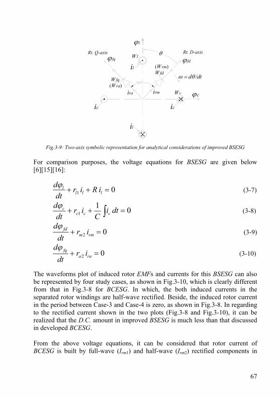
67
WlRt. D-axisRt. Q-axis θ
ω = dθ /dt
ϕc
ϕ l
ϕ fq ϕ fd
Wc
WfdWfq
il
ic
(Wra)
(Wrm)
irmira
il
ic
Fig.3-9: Two-axis symbolic representation for analytical considerations of improved BSESG For comparison purposes, the voltage equations for BSESG are given below [6][15][16]:
01 =++ llll iRir
dtdϕ
(3-7)
011 =++ ∫ dti
Cir
dtd
ccccϕ
(3-8)
02 =+ rmmfd ir
dtdϕ
(3-9)
02 =+ raafq ir
dtdϕ
(3-10)
The waveforms plot of induced rotor EMFs and currents for this BSESG can also be represented by four study cases, as shown in Fig.3-10, which is clearly different from that in Fig.3-8 for BCESG. In which, the both induced currents in the separated rotor windings are half-wave rectified. Beside, the induced rotor current in the period between Case-3 and Case-4 is zero, as shown in Fig.3-8. In regarding to the rectified current shown in the two plots (Fig.3-8 and Fig.3-10), it can be realized that the D.C. amount in improved BSESG is much less than that discussed in developed BCESG. From the above voltage equations, it can be considered that rotor current of BCESG is built by full-wave (Irm1) and half-wave (Irm2) rectified components in
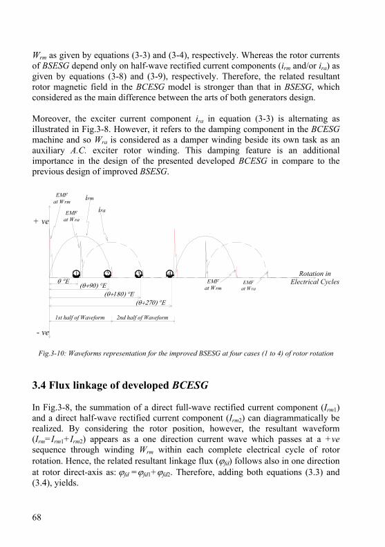
68
Wrm as given by equations (3-3) and (3-4), respectively. Whereas the rotor currents of BSESG depend only on half-wave rectified current components (irm and/or ira) as given by equations (3-8) and (3-9), respectively. Therefore, the related resultant rotor magnetic field in the BCESG model is stronger than that in BSESG, which considered as the main difference between the arts of both generators design. Moreover, the exciter current component ira in equation (3-3) is alternating as illustrated in Fig.3-8. However, it refers to the damping component in the BCESG machine and so Wra is considered as a damper winding beside its own task as an auxiliary A.C. exciter rotor winding. This damping feature is an additional importance in the design of the presented developed BCESG in compare to the previous design of improved BSESG.
(θ+90) °Ε(θ+180) °Ε
(θ+270) °Ε
θ °Ε
+ ve
- ve
Rotation inElectrical Cycles
1st half of Waveform 2nd half of Waveform
ira
irmEMFat Wrm
EMFat Wra
EMFat Wrm
1 2 3 4EMF
at Wra
Fig.3-10: Waveforms representation for the improved BSESG at four cases (1 to 4) of rotor rotation
3.4 Flux linkage of developed BCESG In Fig.3-8, the summation of a direct full-wave rectified current component (Irm1) and a direct half-wave rectified current component (Irm2) can diagrammatically be realized. By considering the rotor position, however, the resultant waveform (Irm=Irm1+Irm2) appears as a one direction current wave which passes at a +ve sequence through winding Wrm within each complete electrical cycle of rotor rotation. Hence, the related resultant linkage flux (ϕfd) follows also in one direction at rotor direct-axis as: ϕfd =ϕfd1+ϕfd2. Therefore, adding both equations (3.3) and (3.4), yields.
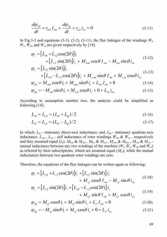
69
022 =+++ raafq
rmmfd ir
dtd
Irdt
d ϕϕ (3-11)
In Fig.3-3 and equations (3-1), (3-2), (3-11), the flux linkages of the windings Wl, Wc, Wrm and Wra are given respectively by [14]:
[ ][ ] ralrarmlrmcc
llll
iMIMiLiLL
θθθθϕ
sincos)2sin()2cos(
2
20
−+++=
(3-12)
[ ][ ] racrarmcrmccc
llc
iMIMiLLiL
θθθθϕ
cossin)2cos()2sin(
20
2
++−+=
(3-13)
0sincos +++= rmrmcrmclrmlfd ILiMiM θθϕ (3-14)
raracraclralfq iLiMiM +++−= 0cossin θθϕ (3-15) According to assumption number two, the analysis could be simplified as following [14]:
2/)(00 QDcl LLLL +== (3-16)
2/)(22 QDcl LLLL −== (3-17) In which: LD - stationary direct-axis inductance; and, LQ - stationary quadrate-axis inductance. Lrm , Lra - self inductance of rotor windings Wrm & Wra , respectively and they assumed equal (Lf). Mlrm & Mrml , Mlra & Mral , Mcrm & Mrmc , Mcra & Mrac - mutual inductance between any two windings of the machine (Wl, Wc, Wrm and Wra) as referred by their subscriptions, which are assumed equal (Mcf), while the mutual inductances between two quadrate rotor windings are zero. Therefore, the equations of the flux linkages can be written again as following:
[ ] [ ]racfrmcf
cclccl
iMIMiLiLL
θθθθϕ
sincos)2sin()2cos( 220
−+++=
(3-18)
[ ] [ ]racfrmcf
ccclcc
iMIMiLLiL
θθθθϕ
cossin)2cos()2sin( 202
++−+=
(3-19)
0sincos +++= rmfccflcffd ILiMiM θθϕ (3-20)
rafccflcffq iLiMiM +++−= 0cossin θθϕ (3-21)
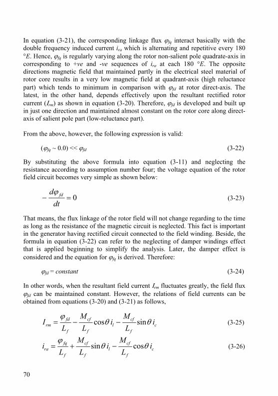
70
In equation (3-21), the corresponding linkage flux ϕfq interact basically with the double frequency induced current ira which is alternating and repetitive every 180 °E. Hence, ϕfq is regularly varying along the rotor non-salient pole quadrate-axis in corresponding to +ve and -ve sequences of ira at each 180 °E. The opposite directions magnetic field that maintained partly in the electrical steel material of rotor core results in a very low magnetic field at quadrant-axis (high reluctance part) which tends to minimum in comparison with ϕfd at rotor direct-axis. The latest, in the other hand, depends effectively upon the resultant rectified rotor current (Ιrm) as shown in equation (3-20). Therefore, ϕfd is developed and built up in just one direction and maintained almost constant on the rotor core along direct-axis of salient pole part (low-reluctance part). From the above, however, the following expression is valid:
(ϕfq ~ 0.0) << ϕfd (3-22) By substituting the above formula into equation (3-11) and neglecting the resistance according to assumption number four; the voltage equation of the rotor field circuit becomes very simple as shown below:
0=−dt
d fdϕ (3-23)
That means, the flux linkage of the rotor field will not change regarding to the time as long as the resistance of the magnetic circuit is neglected. This fact is important in the generator having rectified circuit connected to the field winding. Beside, the formula in equation (3-22) can refer to the neglecting of damper windings effect that is applied beginning to simplify the analysis. Later, the damper effect is considered and the equation for ϕfq is derived. Therefore:
ϕfd = constant (3-24) In other words, when the resultant field current Ιrm fluctuates greatly, the field flux ϕfd can be maintained constant. However, the relations of field currents can be obtained from equations (3-20) and (3-21) as follows,
cf
cfl
f
cf
f
fdrm i
LM
iL
ML
I θθϕ
sincos −−= (3-25)
cf
cfl
f
cf
f
fqra i
LM
iL
ML
i θθϕ
cossin −+= (3-26)
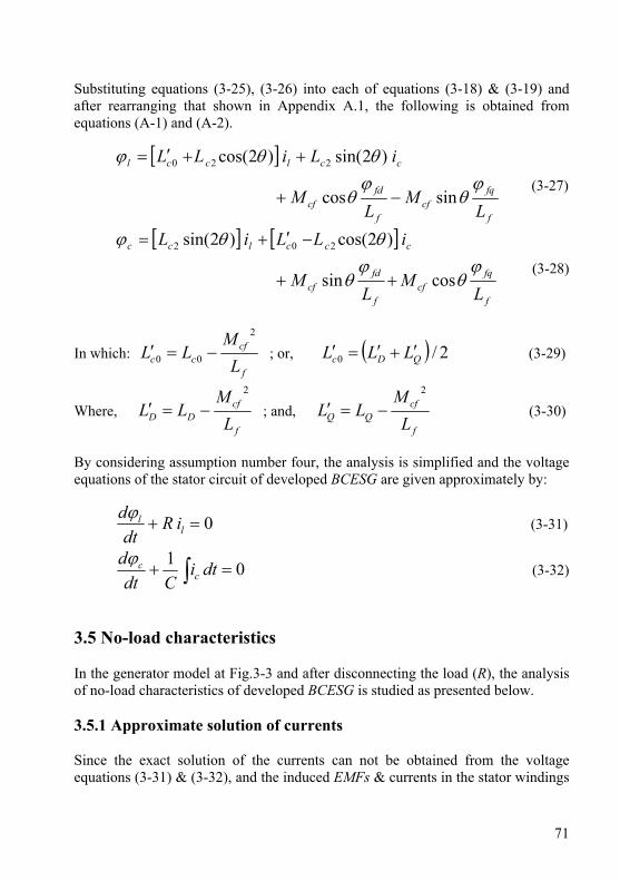
71
Substituting equations (3-25), (3-26) into each of equations (3-18) & (3-19) and after rearranging that shown in Appendix A.1, the following is obtained from equations (A-1) and (A-2).
[ ]
f
fqcf
f
fdcf
cclccl
LM
LM
iLiLLϕ
θϕ
θ
θθϕ
sincos
)2sin()2cos( 220
−+
++′=
(3-27)
[ ] [ ]
f
fqcf
f
fdcf
ccclcc
LM
LM
iLLiLϕ
θϕ
θ
θθϕ
cossin
)2cos()2sin( 202
++
−′+=
(3-28)
In which: f
cfcc L
MLL
2
00 −=′ ; or, ( ) 2/0 QDc LLL ′+′=′ (3-29)
Where, f
cfDD L
MLL
2
−=′ ; and, f
cfQQ L
MLL
2
−=′ (3-30)
By considering assumption number four, the analysis is simplified and the voltage equations of the stator circuit of developed BCESG are given approximately by:
0=+ ll iR
dtdϕ
(3-31)
01=+ ∫ dti
Cdtd
ccϕ
(3-32)
3.5 No-load characteristics In the generator model at Fig.3-3 and after disconnecting the load (R), the analysis of no-load characteristics of developed BCESG is studied as presented below. 3.5.1 Approximate solution of currents Since the exact solution of the currents can not be obtained from the voltage equations (3-31) & (3-32), and the induced EMFs & currents in the stator windings
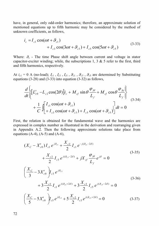
72
have, in general, only odd-order harmonics; therefore, an approximate solution of mentioned equations up to fifth harmonic may be considered by the method of unknown coefficients, as follows,
)5cos()3cos()cos(
5533
11
cccc
ccc
tItItIi
ϑωϑωϑω
+++++=
(3-33)
Where: ϑc - The time Phase shift angle between current and voltage in stator capacitor-exciter winding; while, the subscriptions 1, 3 & 5 refer to the first, third and fifth harmonics, respectively. At ic1 = 0 A (no-load); Ιc1 , Ιc3 , Ιc5 , ϑc1 , ϑc3 , ϑc5 are determined by Substituting equations (3-28) and (3-33) into equation (3-32) as follows,
[ ]
0)cos()cos(
)cos(1
cossin)2cos(
5533
11
20
=⎥⎦
⎤⎢⎣
⎡++++
++
⎪⎭
⎪⎬⎫
⎪⎩
⎪⎨⎧
++−′
∫ dttItI
tIC
LM
LMiLL
dtd
cccc
cc
f
fqcf
f
fdcfccc
ϑωϑωϑω
ϕθ
ϕθθ
(3-34)
First, the relation is obtained for the fundamental wave and the harmonics are expressed in complex number as illustrated in the derivation and rearranging given in Appendix A.2. Then the following approximate solutions take place from equations (A-4), (A-5) and (A-6),
02
2)(
)2(3
2
)2(1
210
3
11
=++
+′−
−
−−
δδϑ
δϑϑ
ϕ j
f
fdcf
jc
c
jc
cjccC
eL
jXeIX
eIX
eIXX
c
cc
(3-35)
02
32
3
33
)2(5
2)2(1
2
30
51
3
=++
⎟⎠⎞
⎜⎝⎛ ′−
−+ δϑδϑ
ϑ
cc
c
jc
cjc
c
jcc
C
eIX
eIX
eIXX
(3-36)
02
555
)2(3
250
35 =+⎟⎠⎞
⎜⎝⎛ ′− + δϑϑ cc j
ccj
ccC eIXeIXX
(3-37)
73
Where: 00 cc LX ′=′ ω ; 22 cc LX ω= ; C
XC ω1
= ; cfcf MX ω=
Also, ff LX ω= , and: 00 cc LX ω=
From equation (3-37), the 5th harmonics current Ic5 can be re-written in terms of 3rd harmonics current as follows:
)2(355
53 ccjcc eIKI ϑδϑ −+−= (3-38)
In which:
⎟⎠⎞
⎜⎝⎛ ′−⎟
⎠⎞
⎜⎝⎛= 02
25 52 c
Cc XXXK (3-39)
By substituting the above component (Ic5) into equation (3-36), the relation will be expressed in terms of 3rd harmonics and fundamental components as shown below,
[ ] 02
3
233
3
)2()2(35
2
)2(1
230
553
13
=−
+⎟⎠⎞
⎜⎝⎛ ′−
−−+
+
δϑϑδϑ
δϑϑ
ccc
cc
jjc
c
jc
cjcc
C
eeIKX
eIX
eIXX
(3-40)
By rearranging the above equation, the 3rd harmonics component of capacitor current is obtained,
)2(133
31 ccjcc eIKI ϑδϑ −+−= (3-41)
In which:
⎥⎦
⎤⎢⎣
⎡⎟⎠⎞
⎜⎝⎛ +′−⎟
⎠⎞
⎜⎝⎛= 5
202
23 232
KXXXXK cc
Cc (3-42)
Therefore, the relation in terms of only fundamental component is obtained easily by substituting relation (3-41) into equation (3-35) and dividing both sides over
δje , as shown in the following:
( ) 02
)(
2
1
1
132
0
)(1
2
=+⎥⎦⎤
⎢⎣⎡ −′−+ −
−−
f
fdcf
jc
ccc
jc
c
LjXeIK
XXX
eIX
c
c
ϕδϑ
δϑ
(3-43)
74
But the time phase shift between the generator terminal voltage (vl) and exciter capacitor voltage (vc) is 90°E. This yields the following definitions for fundamental and harmonics components,
⎪⎪⎪
⎭
⎪⎪⎪
⎬
⎫
−=
+=
−=
25
23
2
5
3
1
πδϑ
πδϑ
πδϑ
c
c
c
(3-44)
After substituting equation (3-44) into relation (3-38), the harmonics component Ic5 may represent in terms of 3rd harmonics component as follows:
( )πππ
πδδπδ
sincos3535
252
23
355
jIKeIK
eIKI
cj
c
j
cc
+−=−=
−=⎥⎦
⎤⎢⎣
⎡⎟⎠⎞
⎜⎝⎛+−+⎟
⎠⎞
⎜⎝⎛+
355 cc IKI = (3-45) In the same manner, substituting equation (3-44) into relation (3-41) yields again harmonics component Ic3 in terms of fundamental current component, as in the following expression:
133 cc IKI = (3-46) Hence, Ic5 may also be expressed in terms of fundamental component as the following,
1355 cc IKKI = (3-47) Moreover, the fundamental current component in the capacitor circuit is solved after substituting equation (3-44) into relation (3-43) and dividing both side over operand “ j ”. Hence:
( ) ⎥⎦
⎤⎢⎣
⎡⎟⎠⎞
⎜⎝⎛ ++′−⎟
⎟⎠
⎞⎜⎜⎝
⎛= 3
201 1
2KXXX
LXI c
cCf
fdcfc
ϕ (3-48)

75
3.5.2 Determination of field flux and angle between load winding and rotor direct axis
Since the field circuit of the rotor of developed BCESG system consists of an effective full-wave rectifying circuit, it is possible to determine the field flux φfd and the angel δ from the boundary conditions. Thus if it is considered that at “t = 0” the electromotive force of the field winding (emfd ) is changed from the negative to the positive voltage with respect to the rectifier and from this instant the condition of the rectifier takes place, then the following boundary conditions exist [12][17][18]:
00 ==trmI (3-49) Substituting this boundary condition at no-load status into flux equation (3-14) yields:
00 sin== =
tccftfd iM θϕ (3-50)
But,
dtd
emf fdd
ϕ−= (3-51)
Hence:
( ) 0sin0
0 =−==
=t
ccftd iMdtdemf θ (3-52)
; and:
( ) 0sin0
2
2
0
>−=== t
ccft
d iMdtdemf
dtd θ (3-53)
The condition of equation (3-52) is, from equations (3-23) and (3-25), the same as:
00
==t
rmIdtd
(3-54)
The solution in equation (3-54) is well illustrated in Appendix A-3. Since the rectified field current flows in the inductance circuit, the rise of the current may be considered as zero. Moreover, since ( )0≥rmI , the minimum value of the field
current may also be considered as zero [6]. By substituting ic of relation (3-33), θ
76
from equation (3-6) and ϑc at equation (3-44) into equation (3-50), the direct-axis field flux linkage (φfd) at boundary condition (t=0) is then given by the following.
05
3
1
0
)2
55cos(
)2
33cos(
)2
cos(
)sin(
=
=
⎥⎥⎥⎥⎥⎥⎥
⎦
⎤
⎢⎢⎢⎢⎢⎢⎢
⎣
⎡
−++
+++
−+
+=
tc
c
c
cftfd
tI
tI
tI
tM
πδω
πδω
πδω
δωϕ (3-55)
; or, [ ])5sin()3sin()sin()sin( 5310 δδδδϕ ccccftfd IIIM +−==
Substituting equations (3-46) and (3-47) into the above relation yields the direct-axis flux linkage (φfd) in terms of fundamental component of capacitor current. Since φfd remains constant according to the formula in equation (3-24) as mentioned above, then:
[ ])5sin()3sin(sinsin 5331 δδδδϕ KKKIM ccffd +−= (3-56) From equations (3-50) and (3-52), the following is considered,
00
0 =−==
=t
fdtd dtdemf ϕ (3-57)
Substituting equation (3-55) into equation (3-56) yields:
0
)2
55cos(
)2
33cos(
)2
cos(
)sin(
05
3
1
0 =
⎪⎪⎪⎪
⎭
⎪⎪⎪⎪
⎬
⎫
⎪⎪⎪⎪
⎩
⎪⎪⎪⎪
⎨
⎧
⎥⎥⎥⎥⎥⎥⎥
⎦
⎤
⎢⎢⎢⎢⎢⎢⎢
⎣
⎡
−++
+++
−+
+
−=
=
=
tc
c
c
cf
td
tI
tI
tI
tM
dtdemf
πδω
πδω
πδω
δω
(3-58)
After some arrangements on the above relation, as shown in Appendix A.4.1, the determinant equation of “δ ” is realized from equation (A-9) as follows:
77
( ) ( )0)6sin(3
)4sin(2)2sin(1
53
5333
=++−+
δδδ
KKKKKK
(3-59)
In similar manner, from equations (3-50) and (3-53) the following is obtained,
( ) 00
2
2
0
>−=== t
fdt
d dtdemf
dtd ϕ (3-60)
Substituting equation (3-55) into equation (3-60) and re-arranging, yields:
0
)55sin()33sin(
)sin(
)sin(
05
3
12
2
0
>
⎪⎪
⎭
⎪⎪
⎬
⎫
⎪⎪
⎩
⎪⎪
⎨
⎧
⎥⎥⎥
⎦
⎤
⎢⎢⎢
⎣
⎡
+++−
+
+
−=
=
=
tc
c
c
cf
td
tItI
tI
tM
dtdemf
dtd
δωδω
δω
δω
(3-61)
After the derivation for the second order that is illustrated in Appendix A.4.2, the value of “ δ “ must from equation (A-10) satisfy the following relation.
( )( ) 0
)6cos(9)4cos(4)2cos(1
53533
31 >⎥
⎦
⎤⎢⎣
⎡++−
+−
δδδ
KKKKKK
Ic (3-62)
From equations (3-56) and (3-62), it is obvious that the field flux changes with the change of angle “ δ “ and it is existed even at “ t = 0 “, which yields the induced field EMF and the field current. It is also clear from the results in the mentioned equations that the condition in equations (3-52) and (3-54) agrees with the conditions of,
0=fddd ϕδ
(3-63)
and, 02
2
<fddd ϕδ
(3-64)
The above results in terms of the changeable angle value “ δ ” are mathematically approved as illustrated in Appendix A.5 and it is realized from relation (3-64) that the field linkage flux will have maximum value and is always kept at maximum.

78
Now the rearranging takes place on equation (3-59) as shown in Appendix 3.6 and from equation (A-13), the solution is at,
0)2sin( =δ (3-65)
or at,
( ) ( ) 031)2cos(4)2(cos12 5335332
53 =−+++− KKKKKKKK δδ Then:
( ) ( )⎥⎦⎤
⎢⎣⎡ −+−±+= 355
255
5
311016
1)2cos( KKKKKK
δ (3-66)
From equation (3-65), two values for δ may obtain. These are “δ=0” and “δ=π/2”. However, by substituting “δ=0” for field linkage flux in equation (3-56), yields:
[ ] 0)0sin()0sin()0sin()0sin( 5331 =+−= KKKIM ccffdϕ This will not express the generation condition. Therefore, the other solution at “ δ = π/2 ” is considered by using equation (3-62). From this equation, δ = π/2 exists in the range of XC which satisfies the following condition:
( ) ( ) 0)2
6cos(9)2
4cos(4)2
2cos(1 5353331 >⎥⎦⎤
⎢⎣⎡ ++−+−
πππ KKKKKKIc
Then, ( ) 01351 5331 >++ KKKIc (3-67) The value for φfd can be given by equation (3-56) as follows,
⎥⎦⎤
⎢⎣⎡ +−= )
25sin()
23sin()
2sin()
2sin( 5331
ππππϕ KKKIM ccffd
( )5331 1 KKKIM ccffd ++=ϕ (3-68) 3.5.3 The nonlinearity due to saturation of magnetic circuit To determine Ic1 , the field flux φfd at equation (3-56) substituted into fundamental component of capacitor current at equation (3-48) to obtain the following relation.
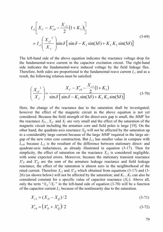
79
( )
[ ])5sin()3sin(sinsin
12
533
2
1
32
01
δδδδ KKKX
XI
KX
XXI
f
cfc
ccCc
+−⎟⎟⎠
⎞⎜⎜⎝
⎛=
⎥⎦⎤
⎢⎣⎡ +−′−
(3-69)
The left-hand side of the above equation indicates the reactance voltage drop for the fundamental-wave current in the capacitor excitation circuit. The right-hand side indicates the fundamental-wave induced voltage by the field linkage flux. Therefore, both sides are proportional to the fundamental-wave current Ic1 and as a result, the following relation must be satisfied:
( )[ ])5sin()3sin(sinsin
12
533
32
02
δδδδ KKK
KXXX
XX
ccC
f
cf
+−
+−′−=⎟
⎟⎠
⎞⎜⎜⎝
⎛ (3-70)
Here, the change of the reactance due to the saturation shall be investigated; however the effect of the magnetic circuit in the above equation is not yet considered. Because the field strength of the direct-axis gap is small, the MMF for the reactance XD , Xcf and Xf are very small and the effect of the saturation of the magnetic circuit including the armature core and field poles is large [19]. On the other hand, the quadrate-axis reactance XQ will not be affected by the saturation up to a considerably large current because of the large MMF required in the large air-gap of the new rotor core construction. But Lc2 has smaller value in compare with Lc0; because Lc2 is the resultant of the difference between stationary direct- and quadrate-axis inductances, as already illustrated in equation (3-17). Then for simplicity, the effect of saturation on the reactance Xc2 is considered negligible, with some expected errors. Moreover, because the stationary transient reactance X'D and X'Q are the sum of the armature leakage reactance and field leakage reactance, the effect of the saturation is almost zero in the neighborhood of the rated current. Therefore Xc2 and X'c0 which obtained from equations (3-17) and (3-26) (as shown below) will not be affected by the saturation; and K3 , K5 can also be considered constant for a specific value of capacitor reactance (XC). Above all, only the term “Xcf
2/Xf ” in the left-hand side of equation (3-70) will be a function of the capacitor current Ic1 because of the nonlinearity due to the saturation.
2/)(2 QDc XXX −= (3-71)
( ) 2/0 QDc XXX ′+′=′ (3-72)

80
For new value of capacitance C, the current Ic1 changes according to the change in capacitor reactance XC. If the right-hand side of equation (3-70) is substituted with parameter values, the term “Xcf
2/Xf ” can easily be obtained; hence, Ic1 is determined from a relation between “Xcf
2/Xf ” and “Ic1” that obtains from measuring the generator constants or design data; beside, the nonlinearity due to the saturation is introduced in the above analysis. By substituting assumed numerical per-unit values for the machine parameters, the nonlinearity of the magnetic circuit is plotted, as shown in Fig.3-11 [20]. In which the relation between the saturation and various reactances of the generator is illustrated.
Vol
tage
(x.I
c1),
Rea
ctan
ce (X
'c0),
(Xcf
²/Xf)
Capacitor Current (I c1)
Quadrature-axis gab
Direct-axis gab
Saturationcurve of core
(X cf ²/X f )
X' c0
X' c0I c1
(X cf ²/X f )I c1
0.0 0.5 1.0 1.5 2.0 2.5 3.0
0.2
0.4
0.6
0.8
1.0
1.2
1.4
1.6MMF required for gap MMF required
for core
( due to
saturation)
Fig.3-11: Nonlinearity due to saturation of magnetic circuit In this case, the value of “Xcf
2/Xf ” has an upper limit determined by the unsaturated part and a lower limit that limited by rated current. The self-generation is possible in this range. Therefore, if the value of XC is selected such that the value of “Xcf
2/Xf ” in equation (3-70) falls in this range, the self-excited generation is possible. When the saturation is sufficient, the value “Xcf
2/Xf ” is smaller than the lower limit and theoretically the generation is possible up to this value. Actually, because an excessive capacitor current flows, the resistance voltage drop of the windings Wc , Wrm , Wra and the effect of the saturation XQ can no longer be neglected, and consequently, the voltage rise before this saturation point is impossible. 3.5.4 Discussion of generation condition & capacitor value at
harmonics waves In general the net reactance of resonant circuit at resonant angular frequency (ω0) is capacitive at frequencies below ω0 and inductive at frequencies above ω0 [21].
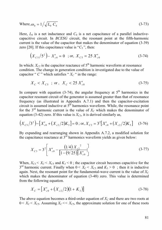
81
Where, 000 1 CL=ω (3-73) Here, L0 is a net inductance and C0 is a net capacitance of a parallel inductive-capacitive circuit. In BCESG circuit, the resonant point at the fifth-harmonic current is the value of the capacitor that makes the denominator of equation (3-39) zero [20]. If this capacitance value is “C5 ”, then:
( ) 05 02
5 =′− cC XX ; or, 05 25 cC XX ′= (3-74) In which: XC5 is the capacitor reactance of 5th harmonic waveform at resonance condition. The change in generation condition is investigated due to the value of capacitor “ C ” which satisfies “ XC “ in the range:
5CC XX < ; or , 025 cC XX ′< (3-75) In compare with equation (3-74), the angular frequency at 5th harmonics in the capacitor resonant circuit of the generator is assumed greater than that of resonance frequency (as illustrated in Appendix A.7.1) and then the capacitor-excitation circuit is assumed inductive at 5th harmonics waveform. While, the resonance point for the 3rd harmonic current is the value of XC which makes the denominator of equation (3-42) zero. If this value is XC3, it is derived similarly as,
( ) ( )[ ] 023 5202
3 =+′− KXXX ccC ; or, ( )[ ]5202
3 23 KXXX ccC +′= (3-76) By expanding and rearranging shown in Appendix A.7.2, a modified solution for the capacitance reactance at 3rd harmonics waveform yields as given below:
( )( )[ ] ⎥
⎦
⎤⎢⎣
⎡′−
−′=0
22
02
3 2591413
c
ccC X
XXX (3-77)
When, XC3 < XC < XC5 and K3 < 0 ; the capacitor circuit becomes capacitive for the 3rd harmonic current. Finally when 0 < XC < XC3 and K3 > 0 ; then it is inductive again. Next, the resonant point for the fundamental-wave current is the value of XC which makes the denominator of equation (3-48) zero. This value is determined from the following equation.
( )( )[ ]320 12 KXXX ccC ++′= (3-78) The above equation becomes a third-order equation of XC and there are two roots at 0 < XC < XC5. Assuming XC << XC5, the approximate solution for one of these roots
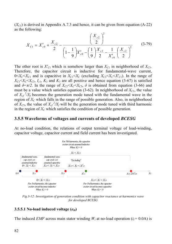
82
(XC1) is derived in Appendix A.7.3 and hence, it can be given from equation (A-22) as the following:
22
0
20
22
201
21
291
911
22
⎟⎠⎞
⎜⎝⎛
′−⎟
⎠⎞
⎜⎝⎛−′⎟
⎠⎞
⎜⎝⎛ −
⎟⎠⎞
⎜⎝⎛
−+′=c
c
cc
c
ccC
XX
XX
XX
XX (3-79)
The other root is X'C1 which is somehow larger than XC1 in neighborhood of XC3. Therefore, the capacitor circuit is inductive for fundamental-wave current, 0<XC<XC1 and is capacitive in XC1<XC (excluding XC3<XC<X'C1). In the range of XC1<XC<XC3, Ic1, K3 and K5 are all positive and hence equation (3-67) is satisfied and δ=π/2. In the range of XC3<XC<XC5, δ is obtained from equation (3-66) and must be a value which satisfies equation (3-62). In neighborhood of XC1, the value of Xcf
2/Xf becomes the generation mode tuned with the fundamental wave in the region of XC which falls in the range of possible generation. Also, in neighborhood of XC3, the value of Xcf
2/Xf will be the generation mode tuned with third harmonic in the region of XC which satisfies the condition of possible generation. 3.5.5 Waveforms of voltages and currents of developed BCESG At no-load condition, the relations of output terminal voltage of load-winding, capacitor voltage, capacitor current and field current has been investigated.
0.0 XC1 XC3 X′C1 XC5=25 X'c0 XC
For 3'rd harmonics, the capacitorexciter circuit becomes inductive
When: K3 > 0
For 5'th harmonics, the capacitorexciter circuit assumed inductive
When: K5 > 0
"Excluding"
For 3'rd harmonics, the capacitorexciter circuit becomes capacitive
When: K3 < 0
fundamental wave,cap. excit. cct.
assumed inductiveXC1 < XC < XC30 < XC < XC1 XC3 < XC < X'C1
0 < XC < XC3 XC3 < XC < XC5
XC < XC5
fundamental wave,cap. excit. cct.
assumed capacitive
Fig.3-12: Investigation of generation condition with capacitor reactance at harmonics wave
for developed BCESG 3.5.5.1 No-load induced voltage (el0) The induced EMF across main stator winding Wl at no-load operation (il = 0.0A) is

83
derived from general equation (3-31) by considering “ ∞=R ” as shown below:
000 ≠−= ll dtde ϕ (3-80)
The effective flux linkage at no-load (φl0) can be defined from equation (3-27) after substituting zero value instead of load current, and by considering the relation (3-22) according to the discussion of article 3.4, equation (3-80) is expanded then simply as follows: explanation
⎟⎟⎠
⎞⎜⎜⎝
⎛+−=
f
fdcfccl L
MiLdtde
ϕθθ cos)2sin(20 (3-81)
The instantaneous value of capacitor current “ ic “ is already defined in equation (3-33) and it can be expanded and rearranged in terms of the fundamental waveform component and load angle (δ) by substituting equations (3-44), (3-46) and (3-47) in the mentioned equation (3-33) to obtain the following.
⎥⎥⎥⎥
⎦
⎤
⎢⎢⎢⎢
⎣
⎡
−++
+++−+=
)2
55cos(
)2
33cos()2
cos(
35
3
1 πδω
πδωπδω
tKK
tKtIi cc
(3-82)
Also, from the maximum capacitor current in equation (3-48), the term
[f
fdcf L
Mϕ
] may define as:
( )⎭⎬⎫
⎩⎨⎧
⎥⎦⎤
⎢⎣⎡ ++′−= 3
201 1
2KLLXI
LM c
cC
cf
fdcf ω
ϕ (3-83)
To obtain a formula for “ el0 ”, the results of equations (3-82), (3-83) and equation (3-6) are substituted into equation (3-81) and the derivation is applied as illustrated in Appendix A.8. Hence from equation (A-23) the following is realized:
( ))77sin()55sin(
)33sin(sin
7050
301100
δωδωδωδω
+++++++=
tEtEtEtIEe
ll
lcll (3-84)
In which:
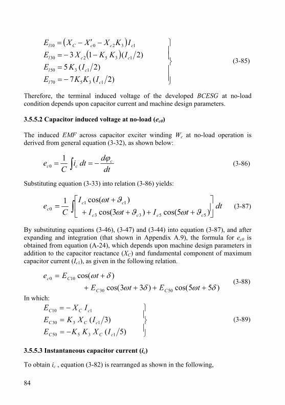
84
( )( )
⎪⎪⎭
⎪⎪⎬
⎫
−==
−−=−′−=
)2(7)2(5
)2(13
13570
1350
135230
132010
cl
cl
ccl
cccCl
IKKEIKE
IKKXEIKXXXE
(3-85)
Therefore, the terminal induced voltage of the developed BCESG at no-load condition depends upon capacitor current and machine design parameters. 3.5.5.2 Capacitor induced voltage at no-load (ec0) The induced EMF across capacitor exciter winding Wc at no-load operation is derived from general equation (3-32), as shown below:
dtddti
Ce c
ccϕ
−== ∫1
0 (3-86)
Substituting equation (3-33) into relation (3-86) yields:
dttItI
tIC
ecccc
ccc ∫ ⎥
⎦
⎤⎢⎣
⎡++++
+=
)5cos()3cos()cos(1
5533
110 ϑωϑω
ϑω (3-87)
By substituting equations (3-46), (3-47) and (3-44) into equation (3-87), and after expanding and integration (that shown in Appendix A.9), the formula for ec0 is obtained from equation (A-24), which depends upon machine design parameters in addition to the capacitor reactance (XC) and fundamental component of maximum capacitor current (Ic1), as given in the following relation.
)55cos()33cos()cos(
5030
100
δωδωδω
+++++=
tEtEtEe
CC
Cc (3-88)
In which:
⎪⎭
⎪⎬
⎫
−==
−=
)5()3(
13550
1330
110
cCC
cCC
cCC
IXKKEIXKE
IXE (3-89)
3.5.5.3 Instantaneous capacitor current (ic) To obtain ic , equation (3-82) is rearranged as shown in the following,
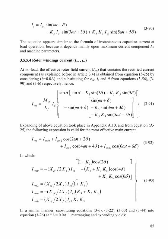
85
)55sin()33sin()sin(
13513
1
δωδωδω
+++−+=
tIKKtIKtIi
cc
cc (3-90)
The equation appears similar to the formula of instantaneous capacitor current at load operation, because it depends mainly upon maximum current component Ic1 and machine parameters. 3.5.5.4 Rotor windings current (Irm , ira) At no-load, the effective rotor field current (Irm) that contains the rectified current component (as explained before in article 3.4) is obtained from equation (3-25) by considering (il=0.0A) and substituting for φfd, ic and θ from equations (3-56), (3-90) and (3-6) respectively, hence:
[ ]
⎪⎪⎭
⎪⎪⎬
⎫
⎪⎪⎩
⎪⎪⎨
⎧
⎥⎥⎥
⎦
⎤
⎢⎢⎢
⎣
⎡
+++−
++−
+−
=
)55sin()33sin(
)sin()sin(
)5sin()3sin(sinsin
35
3
533
1
δωδω
δωδω
δδδδ
tKKtK
tt
KKK
IL
MI c
f
cfrm (3-91)
Expanding of above equation took place in Appendix A.10, and from equation (A-25) the following expression is valid for the rotor effective main current.
)66cos()44cos()22cos(
64
20
δωδωδω
++++++=
tItItIII
rmrm
rmrmrm (3-92)
In which:
( )( )
( )( )
⎪⎪⎪⎪
⎭
⎪⎪⎪⎪
⎬
⎫
=
+−=
+=
⎥⎥⎥
⎦
⎤
⎢⎢⎢
⎣
⎡
++−
+−=
3516
53314
312
53
533
3
10
)2(
)2(
1)2()6cos(
)4cos()2cos(1
)2(
KKIXXI
KKKIXXI
KIXXIKK
KKKK
IXXI
cfcfrm
cfcfrm
cfcfrm
cfcfrm
δδ
δ
(3-93)
In a similar manner, substituting equations (3-6), (3-22), (3-33) and (3-44) into equation (3-26) at “ il = 0.0A ”, rearranging and expanding yields:

86
)66sin()44sin()22sin(
64
2
δωδωδω
+++++=
tItItIi
rara
rara (3-94)
In which:
( )( )
⎪⎭
⎪⎬
⎫
−=
−=
−−=
3516
53314
312
)2(
)2(
1)2(
KKIXXI
KKKIXXI
KIXXI
cfcfra
cfcfra
cfcfra
(3-95)
It is observed from equations (3-92) and (3-94) that the component Irm0 of main field current Irm is constant as long as the angle “ δ “ kept constant, while the auxiliary rotor current ira depends upon components that are alternating within the time, even when δ is kept constant. 3.5.6 Conclusions of analysis at no load condition From the analysis at no-load condition that shown above, it appears mainly that the self-excitation generation is also possible when the capacitor excitation circuit (resonant circuit) is tuned with the third harmonic, in addition to the fundamental wave component. This has been proved in the experimental tests, where the voltage is generated to a standard value with two different values of capacitors in the excitation circuit of the developed BCESG. It is also realized that the rotor field and auxiliary currents (Irm, ira) are dependable mainly upon the maximum fundamental capacitor current component (Ic1), and the latest changes with the changing in value of capacitance. This is also proved in the results of practical tests that shown later at chapter six, where the generator excitation voltage is regulated within the changes in capacitor value. 3.6 Analysis of load characteristics The flux linkages, instantaneous alternating currents for stator and rotor are solved here with emphases on the fundamental wave component. Load angle and phase shift angle are also investigated as shown in the following articles. 3.6.1 Voltage and flux relations at boundary condition After re-connecting the load (R) in the BCESG model (shown in Fig.3-2), the analysis at load characteristics is investigated and an approximate solution is
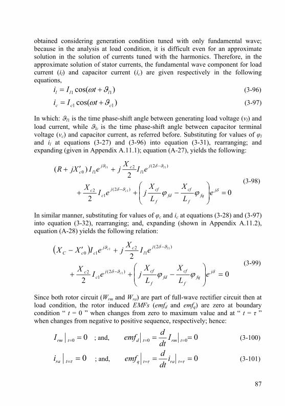
87
obtained considering generation condition tuned with only fundamental wave; because in the analysis at load condition, it is difficult even for an approximate solution in the solution of currents tuned with the harmonics. Therefore, in the approximate solution of stator currents, the fundamental wave component for load current (il) and capacitor current (ic) are given respectively in the following equations,
)cos( 11 lll tIi ϑω += (3-96)
)cos( 11 ccc tIi ϑω += (3-97)
In which: ϑl1 is the time phase-shift angle between generating load voltage (vl) and load current, while ϑlc is the time phase-shift angle between capacitor terminal voltage (vc) and capacitor current, as referred before. Substituting for values of φl and il at equations (3-27) and (3-96) into equation (3-31), rearranging; and expanding (given in Appendix A.11.1); equation (A-27), yields the following:
02
2)(
)2(1
2
)2(1
210
1
11
=⎟⎟⎠
⎞⎜⎜⎝
⎛−++
+′+
−
−
δϑδ
ϑδϑ
ϕϕ jfq
f
cffd
f
cfjc
c
jl
cjlc
eLX
LX
jeIX
eIX
jeIXjR
c
ll
(3-98)
In similar manner, substituting for values of φc and ic at equations (3-28) and (3-97) into equation (3-32), rearranging; and, expanding (shown in Appendix A.11.2), equation (A-28) yields the following relation:
( )
02
2
)2(1
2
)2(1
210
1
11
=⎟⎟⎠
⎞⎜⎜⎝
⎛−++
+′−
−
−
δϑδ
ϑδϑ
ϕϕ jfq
f
cffd
f
cfjc
c
jl
cjccC
eLX
LX
jeIX
eIX
jeIXX
c
lc
(3-99)
Since both rotor circuit (Wrm and Wra) are part of full-wave rectifier circuit then at load condition, the rotor induced EMFs (emfd and emfq) are zero at boundary condition “ t = 0 ” when changes from zero to maximum value and at “ t = τ ” when changes from negative to positive sequence, respectively; hence:
00 ==trmI ; and, 000 == == trmtd Idtdemf (3-100)
0==τtrai ; and, 0== == ττ tratq idtdemf (3-101)
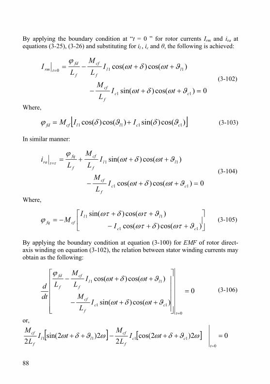
88
By applying the boundary condition at “t = 0 ” for rotor currents Irm and ira at equations (3-25), (3-26) and substituting for il , ic and θ, the following is achieved:
0)cos()sin(
)cos()cos(
11
110
=++−
++−==
ccf
cf
llf
cf
f
fdtrm
ttIL
M
ttIL
ML
I
ϑωδω
ϑωδωϕ
(3-102)
Where,
[ ])cos()sin()cos()cos( 1111 ccllcffd IIM ϑδϑδϕ += (3-103) In similar manner:
0)cos()cos(
)cos()sin(
11
11
=++−
+++==
ccf
cf
llf
cf
f
fqtra
ttIL
M
ttIL
ML
i
ϑωδω
ϑωδωϕ
τ
(3-104)
Where,
⎥⎦
⎤⎢⎣
⎡
++−
++−=
)cos()cos(
)cos()sin(
11
11
cc
llcffq I
IM
ϑωτδωτ
ϑωτδωτϕ (3-105)
By applying the boundary condition at equation (3-100) for EMF of rotor direct-axis winding on equation (3-102), the relation between stator winding currents may obtain as the following:
0)cos()sin(
)cos()cos(
0
11
11
=
⎥⎥⎥⎥⎥
⎦
⎤
⎢⎢⎢⎢⎢
⎣
⎡
++−
++−
=t
ccf
cf
llf
cf
f
fd
ttIL
M
ttIL
ML
dtd
ϑωδω
ϑωδωϕ
(3-106)
or,
[ ] [ ] 02)2cos(2
2)2sin(2
0
1111 =++−++=t
ccf
cfll
f
cf tIL
MtI
LM
ωϑδωωϑδω

89
Hence the condition for the direct axis field is:
)cos()sin( 1111 ccll II ϑδϑδ +=+ (3-107) By the same procedure, equation (3-101) for EMF of rotor quadrate-axis winding at boundary condition “t = τ ” is applied on equation (3-104). After the rearranging that illustrated in Appendix A.11.3 the following yields from equation (A-31).
)2
cos()2
sin( 1111πϑδπϑδ ++=++ ccll II (3-108)
Thus, the solution achieves by considering the phase shift angle 90°E and comparing with equation (3-107). 3.6.2 Instantaneous load and capacitor currents The instantaneous load current (il) and capacitor current (ic) can be obtained now from equations (3-98) and (3-99), as illustrated below:
If “R
X c01tan
′=ϑ ”, as shown in Fig.3-13, then:
( ) 11110
)(1
20
2 cl jccC
jlc eIXXeIXR ϑϑϑ ′−=⎟
⎠⎞⎜
⎝⎛ ′+ +
The magnitude and angle values are:
( ) 12
02
01 cccCl IXRXXI ⎥⎦⎤
⎢⎣⎡ ′+′−= (3-109)
111 )( cl ϑϑϑ =+ (3-110) By substituting equation (3-109) into equation (3-96), the relation for load current value is achieved as follows:
( ) )cos( 112
02
0 lcccCl tIXRXXi ϑω +⎥⎦⎤
⎢⎣⎡ ′+′−= (3-111)
While, by substituting equation (3-110) into equation (3-97), the capacitor current is obtained as follows,
)cos( 111 ϑϑω ++= lcc tIi (3-112)
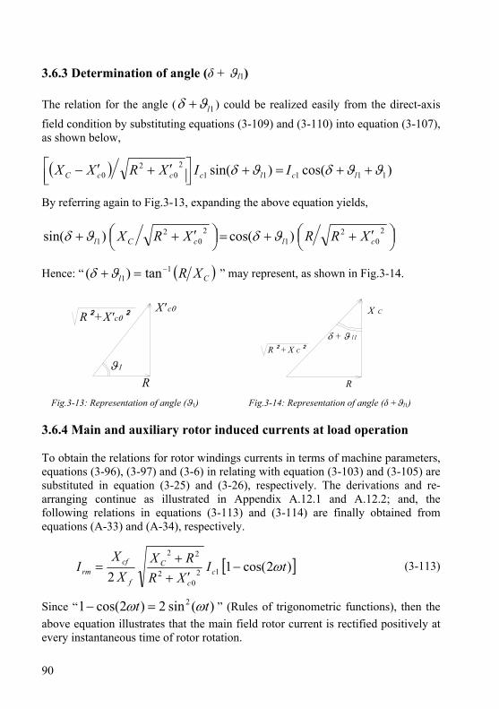
90
3.6.3 Determination of angle (δ + ϑl1) The relation for the angle ( 1lϑδ + ) could be realized easily from the direct-axis field condition by substituting equations (3-109) and (3-110) into equation (3-107), as shown below,
( ) )cos()sin( 111112
02
0 ϑϑδϑδ ++=+⎥⎦⎤
⎢⎣⎡ ′+′− lclcccC IIXRXX
By referring again to Fig.3-13, expanding the above equation yields,
⎟⎠⎞⎜
⎝⎛ ′++=⎟
⎠⎞⎜
⎝⎛ ′++ 2
02
12
02
1 )cos()sin( clcCl XRRXRX ϑδϑδ
Hence: “ ( )Cl XR11 tan)( −=+ϑδ ” may represent, as shown in Fig.3-14.
ϑ1
X' c0
R
R²+X'c0²
X C
R
R ² + X C ²δ + ϑ l1
Fig.3-13: Representation of angle (ϑ1) Fig.3-14: Representation of angle (δ +ϑl1) 3.6.4 Main and auxiliary rotor induced currents at load operation To obtain the relations for rotor windings currents in terms of machine parameters, equations (3-96), (3-97) and (3-6) in relating with equation (3-103) and (3-105) are substituted in equation (3-25) and (3-26), respectively. The derivations and re-arranging continue as illustrated in Appendix A.12.1 and A.12.2; and, the following relations in equations (3-113) and (3-114) are finally obtained from equations (A-33) and (A-34), respectively.
[ ])2cos(12 12
02
22
tIXR
RXX
XI c
c
C
f
cfrm ω−
′++
= (3-113)
Since “ )(sin2)2cos(1 2 tt ωω =− ” (Rules of trigonometric functions), then the above equation illustrates that the main field rotor current is rectified positively at every instantaneous time of rotor rotation.
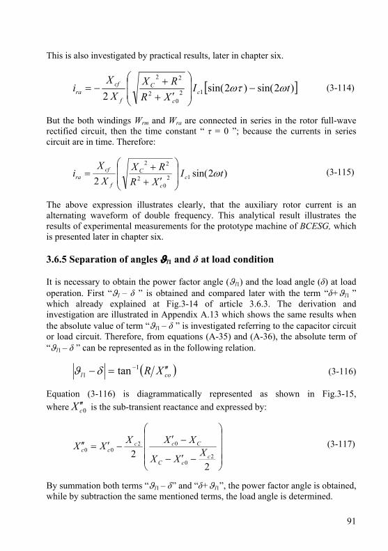
91
This is also investigated by practical results, later in chapter six.
[ ])2sin()2sin(2 12
02
22
tIXR
RXX
Xi c
c
C
f
cfra ωωτ −
⎟⎟
⎠
⎞
⎜⎜
⎝
⎛
′++
−= (3-114)
But the both windings Wrm and Wra are connected in series in the rotor full-wave rectified circuit, then the time constant “ τ = 0 ”; because the currents in series circuit are in time. Therefore:
)2sin(2 12
02
22
tIXR
RXX
Xi c
c
C
f
cfra ω
⎟⎟
⎠
⎞
⎜⎜
⎝
⎛
′++
= (3-115)
The above expression illustrates clearly, that the auxiliary rotor current is an alternating waveform of double frequency. This analytical result illustrates the results of experimental measurements for the prototype machine of BCESG, which is presented later in chapter six. 3.6.5 Separation of angles ϑl1 and δ at load condition It is necessary to obtain the power factor angle (ϑl1) and the load angle (δ) at load operation. First “ϑl – δ ” is obtained and compared later with the term “δ+ϑl1 ” which already explained at Fig.3-14 of article 3.6.3. The derivation and investigation are illustrated in Appendix A.13 which shows the same results when the absolute value of term “ϑl1 – δ ” is investigated referring to the capacitor circuit or load circuit. Therefore, from equations (A-35) and (A-36), the absolute term of “ϑl1 – δ ” can be represented as in the following relation.
( )col XR ′′=− −11 tanδϑ (3-116)
Equation (3-116) is diagrammatically represented as shown in Fig.3-15, where 0cX ′′ is the sub-transient reactance and expressed by:
⎟⎟⎟⎟
⎠
⎞
⎜⎜⎜⎜
⎝
⎛
−′−
−′−′=′′
22 2
0
0200
ccC
Ccccc XXX
XXXXX (3-117)
By summation both terms “ϑl1 – δ” and “δ+ϑl1”, the power factor angle is obtained, while by subtraction the same mentioned terms, the load angle is determined.
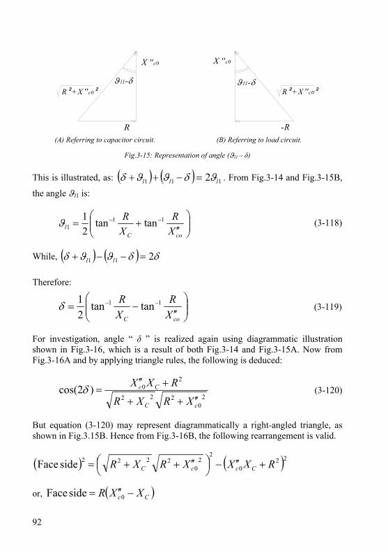
92
ϑ l1-δ
X ''c0 X ''c0
-R
R² +X ''c0²ϑ l1-δ
R² +X ''c0²
(A) Referring to capacitor circuit. (B) Referring to load circuit.
Fig.3-15: Representation of angle (ϑl1 – δ) This is illustrated, as: ( ) ( ) 111 2 lll ϑδϑϑδ =−++ . From Fig.3-14 and Fig.3-15B,
the angle ϑl1 is:
⎟⎟⎠
⎞⎜⎜⎝
⎛′′
+= −−
coCl X
RXR 11
1 tantan21ϑ (3-118)
While, ( ) ( ) δδϑϑδ 211 =−−+ ll Therefore:
⎟⎟⎠
⎞⎜⎜⎝
⎛′′
−= −−
coC XR
XR 11 tantan
21δ (3-119)
For investigation, angle “ δ ” is realized again using diagrammatic illustration shown in Fig.3-16, which is a result of both Fig.3-14 and Fig.3-15A. Now from Fig.3-16A and by applying triangle rules, the following is deduced:
20
222
20cos(2
cC
Cc
XRXR
RXX′′++
+′′=)δ (3-120)
But equation (3-120) may represent diagrammatically a right-angled triangle, as shown in Fig.3.15B. Hence from Fig.3-16B, the following rearrangement is valid.
( ) ( )220
22
02222 side Face RXXXRXR CccC +′′−⎟
⎠⎞⎜
⎝⎛ ′′++=
or, ( )Cc XXR −′′= 0side Face
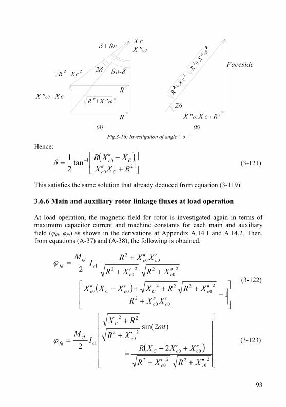
93
ϑ l1-δ
X ''c0
R² +X ''c0²
X C
R² +X C²
δ +ϑ l1
2δ
RX ''c0 - X C
R²+X ''c0
²
R²+X C²
2δX ''c0 X C + R²
Faceside
(A) (B)
Fig.3-16: Investigation of angle ” δ ”
Hence:
( )⎥⎦
⎤⎢⎣
⎡+′′
−′′= −
20
01tan21
RXXXXR
Cc
Ccδ (3-121)
This satisfies the same solution that already deduced from equation (3-119). 3.6.6 Main and auxiliary rotor linkage fluxes at load operation At load operation, the magnetic field for rotor is investigated again in terms of maximum capacitor current and machine constants for each main and auxiliary field (φfd, φfq) as shown in the derivations at Appendix A.14.1 and A.14.2. Then, from equations (A-37) and (A-38), the following is obtained.
( )⎥⎥
⎦
⎤
⎢⎢
⎣
⎡−
′′′+
′′+++′−′′
′′+′+
′′′+=
1
2
002
20
22200
20
220
2
002
1
cc
cCcCc
cc
ccc
cffd
XXRXRRXXXX
XRXR
XXRI
Mϕ
(3-122)
( )⎥⎥⎥⎥⎥⎥
⎦
⎤
⎢⎢⎢⎢⎢⎢
⎣
⎡
′′+′+
′′+′−+
′+
+
=
20
220
2
00
20
2
22
12
)2sin(
2
cc
ccC
c
C
ccf
fq
XRXR
XXXR
tXR
RX
IM
ω
ϕ (3-123)
94
The relation in equation (3-122) that derived for direct-axis main field flux is independent of time and hence φfq remains permanent through the BCESG load operation. While, according to equation (3-123) which derived for quadrate-axis auxiliary rotor flux and since one term of the field flux depends on time (t), then φfq is considered alternating at load operation in compare to the rotor main field “φfd ”. 3.7 Instantaneous load and capacitor voltages When the load (R) is connected to the load circuit at BCESG system shown in Fig.3-2, then the load voltage (vl), which represent the generator terminal output voltage is equal to the instantaneous EMF induced across load winding (el), as long as the voltage drop across the internal resistance of load winding “rl” is neglected, according to assumption number four at article 3.1.2. Similarly, the voltage across the capacitor terminals (vc) is equal to the induced EMF across the capacitor exciter winding (ec) when the voltage drop on the internal resistance of capacitor winding “rc” is neglected. The relations are illustrated as in the following. 3.7.1 Terminal load voltage (vl ) After neglecting the internal resistance as mentioned above, then:
lll iRev == (3-124) Now, substituting equations (3-96) and (3-109) into the above relation yields:
)cos( 11 lll tIRv ϑω += ; or, )cos( 11 lll tEv ϑω += (3-125) In which:
120
2
01 c
c
cCl I
XR
XXRE ⎟⎟
⎠
⎞
⎜⎜
⎝
⎛
′+
′−= (3-126)
3.7.2 Terminal capacitor voltage (vc) In a similar manner given in article 3.7.1,
∫== dtiC
ev ccc1
(3-127)
But “ ic ” is given already in equation (3-112), hence:

95
)sin()cos(1111111 ϑϑωϑϑω ++=++= ∫ lcClcc tIXdttI
Cv ; or,
)sin( 111 lcc tEv ϑϑω ++= (3-128)
In which:
11 cCc IXE = (3-129) 3.8 Determination of the saturation coefficient “Xcf
2/Xf ” at load condition
Similar to the study in article 3.5.3, the determination condition of capacitor current Ic1 at load operation is obtained from a relation between saturation (nonlinearity) coefficient and capacitor value as shown below; which is obtained from equation (A-39) after series of derivations illustrated in Appendix A.15.
( )( )
( )
⎥⎥⎥⎥⎥⎥
⎦
⎤
⎢⎢⎢⎢⎢⎢
⎣
⎡
′′′+
⎟⎟
⎠
⎞
⎜⎜
⎝
⎛
′′+++
′−′′
−
⎥⎦
⎤⎢⎣
⎡′′′+′′′−
−−′−
=
002
20
222
00
002
00202
121
12
cc
cC
cCc
cc
ccCccC
f
cf
XXRXRRX
XXXXXRXXXX
XX
XX (3-130)
3.9 Characteristics study and comparison In this section, the analytical equations and characteristics of previous primarily and improved models’ of BSESG are plotted [7][12][22], then discussed and compared with the characteristics of the presented developed BCESG, as follows. 3.9.1 Analytical study of previous primarily BSESG model Before improvement, the primarily model of BSESG has been built with one stator winding and one rotor winding with half-wave rectified diode, as shown in the

96
circuit diagram of Fig.3-1. Following the previous assumptions in article 3.1.2, the field linkage flux φfd that is proportional to field current irm is considered constant. Hence, the voltage equation is [8][23]:
01=+ ∫ dti
Cdtd
clϕ
(3-131)
In which:
[ ]rm
fdlrmllll L
MiLLϕ
θθϕ cos)2cos(20 +′+′= (3-132)
⎪⎭
⎪⎬
⎫
−=′
−′=′
+′=′
2/)(
2/)(
2/)(
2
0
QDD
QDl
QDl
LLL
LLL
LLL
(3-133)
The relations between the currents are:
Rcl iii += (3-134)
Rc iRdtiC
=∫1
(3-135)
As an approximate solution of the currents, the fundamental wave component for generator induced EMF (El1) is considered and the solutions of field current (irm), which satisfy the boundary conditions of field circuit, are obtained, as in the following:
1221 l
C
Cl I
XR
XRE+
= (3-136)
lrm
lrm
rm
fdrm i
LM
Li θ
ϕcos−= (3-137)
For comparison reason, the formulas related to analyzing of this primary model of brushless self-excited machine and determination condition of load current (Il1) are illustrated [23], as shown in Appendix A.16. Fig.A-1 shows a theoretically calculated characteristics for assumed numerical parameters’ of the generator at a value of XC = 1.1 Ω, [8]. Since the curve Xcf
2/Xf becomes larger as the load

97
increases, the voltage will drop. That is, when the load current increases, part of the leading MMF of the armature current due to the capacitor current is neglected and the terminal voltage will drop [23]. As a result, the capacitor current also decreases, the excitation effect due to the leading current is weakened, and the field current due to the negative-sequence rotating field decreases. Therefore, the machine has only shunt-generator characteristics for the increase of the load current. Hence, for this previous primarily BSESG type, the voltage compensation does not exist and the self-excited generation will not take place at high loads. 3.9.2 Analytical study of the improved BSESG model In the improved model and as illustrated briefly in articles 2.2.1 and 2.2.10, additional separately windings are inserted in the stator and rotor cores, then the self-excitation effect due to the leading capacitor current and the self-excitation effect of the rotor field act accumulatively; then a compound-generator characteristic is obtained in the improved BSESG (previous BCESG) instead of only shunt-generator characteristic that obtained in the primarily models. The circuit diagram of the improved BSESG is shown in Fig.2-11A and Fig.2-21A. The main analytical equations of the generator system, beginning from voltages equations are listed below [18][24]; and for comparison purpose, the remaining derived equations and solutions are shown in Appendix A.17.
0=+ ll iR
dtdϕ
(3-138)
01=+ ∫ dti
Cdtd
ccϕ
(3-139)
0=dt
d fdϕ (3-140)
0=dt
d fqϕ (3-141)
In which, the approximate solution for fluxes are:
θϕθϕϕ sincos0 fqf
cffd
f
cflll L
ML
MiL ++′= (3-142)
θϕθϕϕ cossin0 fqf
cffd
f
cfclc L
ML
MiL −+′= (3-143)
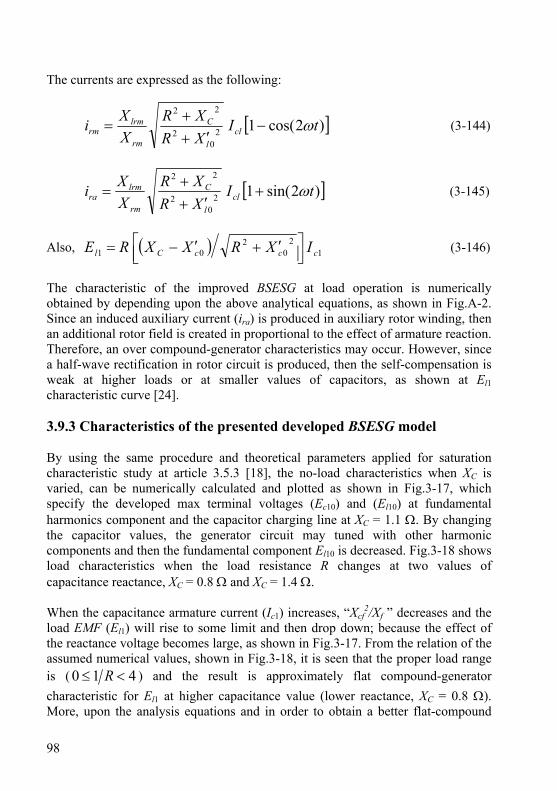
98
The currents are expressed as the following:
[ ])2cos(120
2
22
tIXRXR
XXi cl
l
C
rm
lrmrm ω−
′++
= (3-144)
[ ])2sin(120
2
22
tIXRXR
XXi cl
l
C
rm
lrmra ω+
′++
= (3-145)
Also, ( ) 12
02
01 cccCl IXRXXRE ⎥⎦⎤
⎢⎣⎡ ′+′−= (3-146)
The characteristic of the improved BSESG at load operation is numerically obtained by depending upon the above analytical equations, as shown in Fig.A-2. Since an induced auxiliary current (ira) is produced in auxiliary rotor winding, then an additional rotor field is created in proportional to the effect of armature reaction. Therefore, an over compound-generator characteristics may occur. However, since a half-wave rectification in rotor circuit is produced, then the self-compensation is weak at higher loads or at smaller values of capacitors, as shown at El1 characteristic curve [24]. 3.9.3 Characteristics of the presented developed BSESG model By using the same procedure and theoretical parameters applied for saturation characteristic study at article 3.5.3 [18], the no-load characteristics when XC is varied, can be numerically calculated and plotted as shown in Fig.3-17, which specify the developed max terminal voltages (Ec10) and (El10) at fundamental harmonics component and the capacitor charging line at XC = 1.1 Ω. By changing the capacitor values, the generator circuit may tuned with other harmonic components and then the fundamental component El10 is decreased. Fig.3-18 shows load characteristics when the load resistance R changes at two values of capacitance reactance, XC = 0.8 Ω and XC = 1.4 Ω. When the capacitance armature current (Ic1) increases, “Xcf
2/Xf ” decreases and the load EMF (El1) will rise to some limit and then drop down; because the effect of the reactance voltage becomes large, as shown in Fig.3-17. From the relation of the assumed numerical values, shown in Fig.3-18, it is seen that the proper load range is ( 410 <≤ R ) and the result is approximately flat compound-generator characteristic for El1 at higher capacitance value (lower reactance, XC = 0.8 Ω). More, upon the analysis equations and in order to obtain a better flat-compound
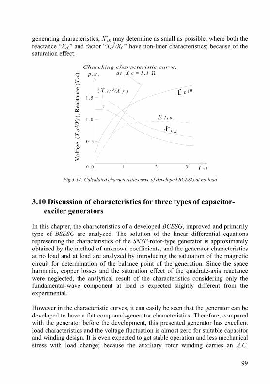
99
generating characteristics, X'c0 may determine as small as possible, where both the reactance “Xc0” and factor “Xcf
2/Xf ” have non-liner characteristics; because of the saturation effect.
0 .0 1 2 3
0 .5
Vol
tage
, (X
cf²/X
f), R
eact
ance
(Xc0
) a t X C = 1 .1 Ω
E c 1 0( X c f ² /X f )
1 .0
1 .5
I c 1
E l 1 0
X C 0
p .u .
Fig.3-17: Calculated characteristic curve of developed BCESG at no-load 3.10 Discussion of characteristics for three types of capacitor-
exciter generators In this chapter, the characteristics of a developed BCESG, improved and primarily type of BSESG are analyzed. The solution of the linear differential equations representing the characteristics of the SNSP-rotor-type generator is approximately obtained by the method of unknown coefficients, and the generator characteristics at no load and at load are analyzed by introducing the saturation of the magnetic circuit for determination of the balance point of the generation. Since the space harmonic, copper losses and the saturation effect of the quadrate-axis reactance were neglected, the analytical result of the characteristics considering only the fundamental-wave component at load is expected slightly different from the experimental. However in the characteristic curves, it can easily be seen that the generator can be developed to have a flat compound-generator characteristics. Therefore, compared with the generator before the development, this presented generator has excellent load characteristics and the voltage fluctuation is almost zero for suitable capacitor and winding design. It is even expected to get stable operation and less mechanical stress with load change; because the auxiliary rotor winding carries an A.C.
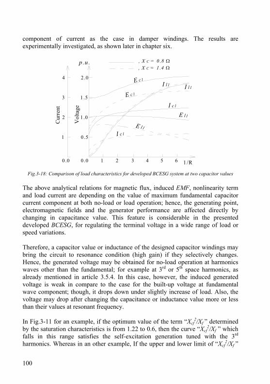
100
component of current as the case in damper windings. The results are experimentally investigated, as shown later in chapter six.
Cur
rent
1 /R0 .0 1 2 3 4 5 6
0 .5
1 .0
1 .5
2 .0
0 .0
1
2
3
4V
olta
ge
E l1
I c1
E c1
I l1
I c1
E c1
I l1
E l1
, X C = 1 .4 Ω, X C = 0 .8 Ωp .u .
Fig.3-18: Comparison of load characteristics for developed BCESG system at two capacitor values The above analytical relations for magnetic flux, induced EMF, nonlinearity term and load current are depending on the value of maximum fundamental capacitor current component at both no-load or load operation; hence, the generating point, electromagnetic fields and the generator performance are affected directly by changing in capacitance value. This feature is considerable in the presented developed BCESG, for regulating the terminal voltage in a wide range of load or speed variations. Therefore, a capacitor value or inductance of the designed capacitor windings may bring the circuit to resonance condition (high gain) if they selectively changes. Hence, the generated voltage may be obtained for no-load operation at harmonics waves other than the fundamental; for example at 3rd or 5th space harmonics, as already mentioned in article 3.5.4. In this case, however, the induced generated voltage is weak in compare to the case for the built-up voltage at fundamental wave component; though, it drops down under slightly increase of load. Also, the voltage may drop after changing the capacitance or inductance value more or less than their values at resonant frequency. In Fig.3-11 for an example, if the optimum value of the term “Xcf
2/Xf ” determined by the saturation characteristics is from 1.22 to 0.6, then the curve “Xcf
2/Xf ” which falls in this range satisfies the self-excitation generation tuned with the 3rd harmonics. Whereas in an other example, If the upper and lower limit of “Xcf
2/Xf ”
101
are assumed to be 1.0 and 0.5, respectively; then in this case, the generation tuned with the fundamental wave is obtained in a region and the generation tuned with the 3rd harmonic wave may obtain in both regions. The fact that the fundamental-wave resonant point X'C1 exists in the neighborhood of the 3rd harmonic resonant point XC3 , as shown in Fig.3-12, can be considered the generation tuned with the 3rd harmonic; however, it does also indicate the possibility of the generation of the fundamental-wave component. If the fundamental-wave-tuned generation is impossible with capacitor variation, the mode of generation can be changed and the fundamental-wave-tuned generation can be made possible by adding an inductance in series with the capacitor excitation circuit. In other words, the generation tuned with the third harmonic can be transferred to the generation tuned with the fundamental wave by changing the design of the stator capacitor-exciter winding and/or selecting other suitable capacitor value. Moreover, it can be seen from Fig.3-8 and equation (3-123) at load operation, there is an alternating component of φfq that changes with time due to the induced double frequency current in rotor circuit. This is useful to obtain same effects of damper windings, explained before. From other side and due to the A.C. current component, the two opposite directions varying magnetic field along the quadrate-axis core is reduced through each complete electrical cycle and then does not directly affects the main rotor field. In addition, the high reluctance at non-salient quadrate-axis part of rotor core also reduces the effects of φfq to minimum. Therefore, the operation of developed BCESG system is kept mechanically stable. However, only main direct-axis field is existed in primarily BSESG. Hence, in compare, no damper windings effect is existed and the rotor main field is independent of time but weak, as shown in equation (3-141). In the improved BSESG type, the induced currents in the rotor circuit are half-wave rectified and the flux linkages for direct- and quadrate-axis are considered constant as given in equation (3-164) and equation (3-165). Thus here also, no damper windings advantages can be existed. By comparing the characteristics of three models types of capacitor-exciter generators given in articles 3.6, 3.9.1 and 3.9.2, at constant capacitance reactance value XC=1.1Ω, the following may obtain, which is also illustrated in the summery of characteristics curves in Fig.3-19.
1- At no-load (R = 0 Ω), the value of the fundamental induced E.M.F, Ec1 or El1 at primarily model is approximately equal to the value of Ec1 in improved model; and, it is also close to Ec1 value in the developed model, as shown in Fig.3-19. However, in comparison to other two types at same capacitance value, the self-excitation is stronger in the developed BCESG. This is the reason why the characteristics curve of developed model starting at little higher value than the other two models’ curves.
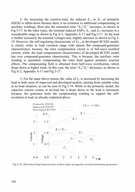
102
2- By increasing the resistive-load, the induced Ec1 or El1 of primarily BSESG is fallen-down because there is no existence to additional compensating or auxiliary windings. Here also the saturation term “Xcf
2/Xf ” increases, as shown in Fig.3-17. In the other types, the terminal induced EMFs, Ec1 and El1 increases in a considerable range as shown in Fig.A-2, Appendix A-17 and Fig.3-17. As the load is further increased, the terminal voltages may slightly decrease as shown in Fig.3-19. However, the self-regulating characteristic of El1 , in developed BCESG model, is clearly wider in load variation range with almost flat compound-generator characteristics; because, the rotor compensation circuit is of full-wave rectified current; while, the load compensation characteristics of developed BCESG model has over compound-generator characteristic. This is because; the auxiliary rotor winding is separately compensating the rotor field against armature reaction effects. The compensating field is obtained from half-wave rectification, which drops down at higher loads. In this case, the term “Xcf
2/Xf ” decreases, as shown in Fig.A-2, Appendix A-17 and Fig.3-17.
3- For the same above reason, the value of Ic1 is increased by increasing the load in both cases of improved and developed models, starting from suitable value at no-load situation, as can be seen in Fig.3-19. While in the primarily model, the capacitor current creates at no-load but it drops down as the load is increased; because, the generator lacks the compensating winding to support the self-excitation at load, as already explained above.
Cur
rent
0 .5
1 .0
1 .5
0 .0
1
2
3
Vol
tage
(X C = 1 .1 Ω )
I c1
E l1= E c 1
0 .0 1 2 3 4 5 6
E l1I c 1
E c1
E l1
I c1
P rim a rily B S E S GIm p ro v e d B S E S G
E c1
D e v e lo p e d B C E S G
p .u .
Fig.3-19: Theoretical load characteristics of three types of capacitor-excited synchronous generators
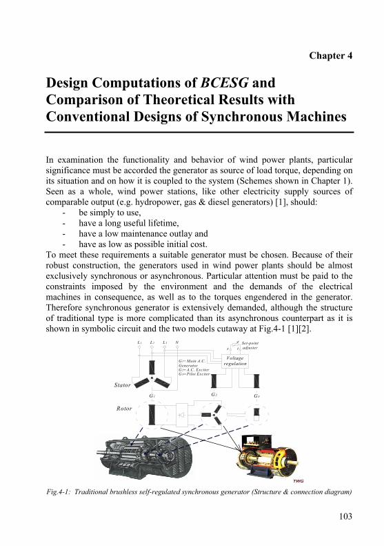
103
Chapter 4
Design Computations of BCESG and Comparison of Theoretical Results with Conventional Designs of Synchronous Machines
In examination the functionality and behavior of wind power plants, particular significance must be accorded the generator as source of load torque, depending on its situation and on how it is coupled to the system (Schemes shown in Chapter 1). Seen as a whole, wind power stations, like other electricity supply sources of comparable output (e.g. hydropower, gas & diesel generators) [1], should:
- be simply to use, - have a long useful lifetime, - have a low maintenance outlay and - have as low as possible initial cost.
To meet these requirements a suitable generator must be chosen. Because of their robust construction, the generators used in wind power plants should be almost exclusively synchronous or asynchronous. Particular attention must be paid to the constraints imposed by the environment and the demands of the electrical machines in consequence, as well as to the torques engendered in the generator. Therefore synchronous generator is extensively demanded, although the structure of traditional type is more complicated than its asynchronous counterpart as it is shown in symbolic circuit and the two models cutaway at Fig.4-1 [1][2].
Fig.4-1: Traditional brushless self-regulated synchronous generator (Structure & connection diagram) A
G 3G 2
Stator
G 1=Main A.C.GeneratorG2=A.C. ExciterG 3=Pilot Exciter
L 1 L 2 L 3 N
Rotor
Voltageregulation
s tSet-pointadjuster
G 1
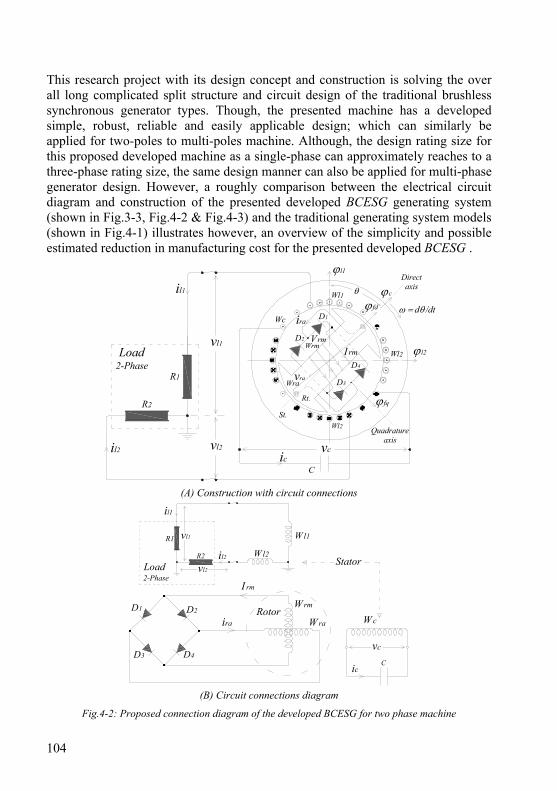
104
This research project with its design concept and construction is solving the over all long complicated split structure and circuit design of the traditional brushless synchronous generator types. Though, the presented machine has a developed simple, robust, reliable and easily applicable design; which can similarly be applied for two-poles to multi-poles machine. Although, the design rating size for this proposed developed machine as a single-phase can approximately reaches to a three-phase rating size, the same design manner can also be applied for multi-phase generator design. However, a roughly comparison between the electrical circuit diagram and construction of the presented developed BCESG generating system (shown in Fig.3-3, Fig.4-2 & Fig.4-3) and the traditional generating system models (shown in Fig.4-1) illustrates however, an overview of the simplicity and possible estimated reduction in manufacturing cost for the presented developed BCESG .
D1
D2
D4
D3
Wl1
WrmLoad
2-Phase
vl2
C
Directaxis
Quadratureaxis
R1
θ
ω = dθ /dt
St.
Rt.
il1
vcic
ira
I rm
vraWra
Vrm
l1
ϕ fq
ϕ fd
vl1
R2
il2
Wl2
Wl2 ϕ l2
Wc
ϕc
(A) Construction with circuit connections
I rm
D1
ira W ra
W rmD2
D3 D4
vl1
il1
R2
R1
il2
Wl1
Wl2Stator
RotorW c
Cic
vc
vl2Load2-Phase
(B) Circuit connections diagram
Fig.4-2: Proposed connection diagram of the developed BCESG for two phase machine
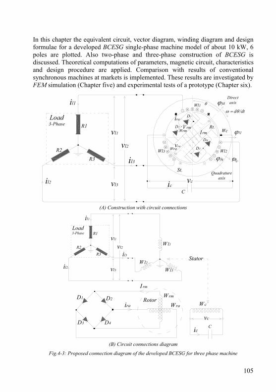
105
In this chapter the equivalent circuit, vector diagram, winding diagram and design formulae for a developed BCESG single-phase machine model of about 10 kW, 6 poles are plotted. Also two-phase and three-phase construction of BCESG is discussed. Theoretical computations of parameters, magnetic circuit, characteristics and design procedure are applied. Comparison with results of conventional synchronous machines at markets is implemented. These results are investigated by FEM simulation (Chapter five) and experimental tests of a prototype (Chapter six).
D1
D2
D4
D3
Wl1
WcWrm
Load3-Phase
vl1
C
Directaxis
Quadratureaxis
θ
ω = dθ /dt
St.
Rt.
il1
vcic
ira
I rm
vraWra
V rmϕ l1
ϕ fq ϕc
ϕ fd
R2
R3
R1
vl3
vl2Wl2Wl3
il2
il3
(A) Construction with circuit connections
I rm
D1
ira Wra
WrmD2
D3 D4
Load3-Phase
vl1
R2R3
R1
vl3
vl2
il2
il3
Wl1
Wl3
Wl2Stator
RotorWc
Cic
vc
il1
(B) Circuit connections diagram
Fig.4-3: Proposed connection diagram of the developed BCESG for three phase machine
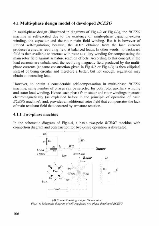
106
4.1 Multi-phase design model of developed BCESG In multi-phase design (illustrated in diagrams of Fig.4-2 or Fig.4-3), the BCESG machine is self-excited due to the existence of single-phase capacitor-exciter winding, the capacitor and the rotor main field winding. But it is however of limited self-regulation; because, the MMF obtained from the load currents produces a circular revolving field at balanced loads. In other words, no backward field is then available to interact with rotor auxiliary winding for compensating the main rotor field against armature reaction effects. According to this concept, if the load currents are unbalanced, the revolving magnetic field produced by the multi-phase currents (at same construction given in Fig.4-2 or Fig.4-3) is then elliptical instead of being circular and therefore a better, but not enough, regulation may obtain at increasing load. However, to obtain a considerable self-compensation in multi-phase BCESG machine, same number of phases can be selected for both rotor auxiliary winding and stator load winding. Hence, each phase from stator and rotor windings interacts electromagnetically (as explained before in the principle of operation of basic BCESG machine); and, provides an additional rotor field that compensates the lack of main resultant field that occurred by armature reaction. 4.1.1 Two-phase machine In the schematic diagram of Fig.4-4, a basic two-pole BCESG machine with connection diagram and construction for two-phase operation is illustrated.
+
-
Rotor
Stator
vl1
il1
R2
R1
il2
Wl1
Wl2
vl2Load2-Phase
ic
Cvc
WcVrm
D3
Wra2 Wra1
Wrm
Irm
D4D1
D2
ira2
ira1
vra1
vra2
direct-axis
(A) Connection diagram for the machine Fig.4-4: Schematic diagram of self-regulated two-phase developed BCESG
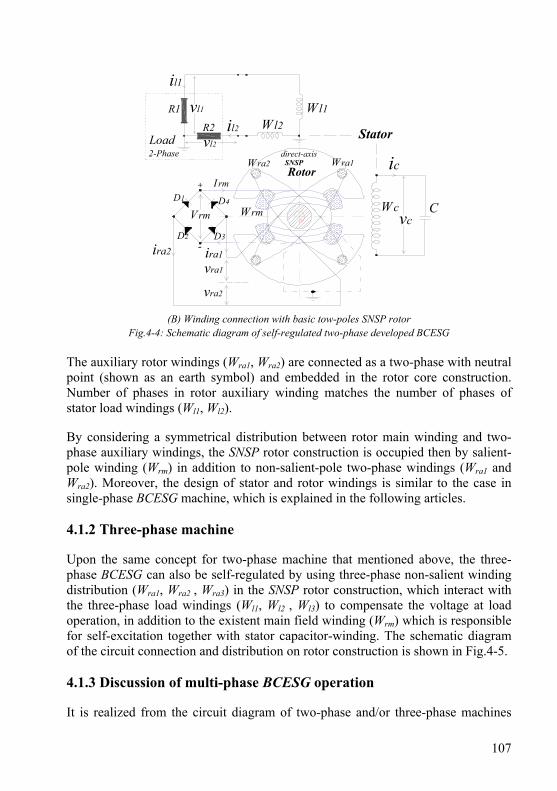
107
SNSPRotor
Stator
+
-
vl1
l1
R2
R1
il2
Wl1Wl2
vl2Load2-Phase
ic
Cvc
Wc
IrmD1 D4
D2 D3
Vrm
ira1
vra2
Wra1Wra2
Wrm
vra1
ira2
direct-axis
(B) Winding connection with basic tow-poles SNSP rotor
Fig.4-4: Schematic diagram of self-regulated two-phase developed BCESG The auxiliary rotor windings (Wra1, Wra2) are connected as a two-phase with neutral point (shown as an earth symbol) and embedded in the rotor core construction. Number of phases in rotor auxiliary winding matches the number of phases of stator load windings (Wl1, Wl2). By considering a symmetrical distribution between rotor main winding and two-phase auxiliary windings, the SNSP rotor construction is occupied then by salient-pole winding (Wrm) in addition to non-salient-pole two-phase windings (Wra1 and Wra2). Moreover, the design of stator and rotor windings is similar to the case in single-phase BCESG machine, which is explained in the following articles. 4.1.2 Three-phase machine Upon the same concept for two-phase machine that mentioned above, the three-phase BCESG can also be self-regulated by using three-phase non-salient winding distribution (Wra1, Wra2 , Wra3) in the SNSP rotor construction, which interact with the three-phase load windings (Wl1, Wl2 , Wl3) to compensate the voltage at load operation, in addition to the existent main field winding (Wrm) which is responsible for self-excitation together with stator capacitor-winding. The schematic diagram of the circuit connection and distribution on rotor construction is shown in Fig.4-5. 4.1.3 Discussion of multi-phase BCESG operation It is realized from the circuit diagram of two-phase and/or three-phase machines
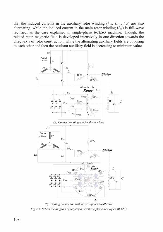
108
that the induced currents in the auxiliary rotor winding (ira1, ira2 , ira3) are also alternating, while the induced current in the main rotor winding (Irm) is full-wave rectified, as the case explained in single-phase BCESG machine. Though, the related main magnetic field is developed intensively in one direction towards the direct-axis of rotor construction, while the alternating auxiliary fields are opposing to each other and then the resultant auxiliary field is decreasing to minimum value.
Load3-Phase
vl1
R2R3
R1
vl3
vl2
il2
il3
Wl1
Wl3
Wl2
il1
ic
Cvc
WcWra2
Wra3
Wra1
+
-
Vrm
Irm
D1D5 D3
D2D6 D4
Wrmira1
ira2
ira3
Stator
Rotor
vra2vra3
vra1
direct-axis
(A) Connection diagram for the machine
SNSPRotor
Stator
+
-
Load3-Phase
vl1
R2R3
R1
vl3
vl2
il2
il3
Wl1
Wl3
Wl2
il1
ic
C
Wra1
Wra2 Wra3
WrmVrm
Irmira1
ira3
ira2
D1D5 D3
D2D6 D4
Wcvc
direct-axis
(B) Winding connection with basic 2-poles SNSP rotor
Fig.4-5: Schematic diagram of self-regulated three-phase developed BCESG
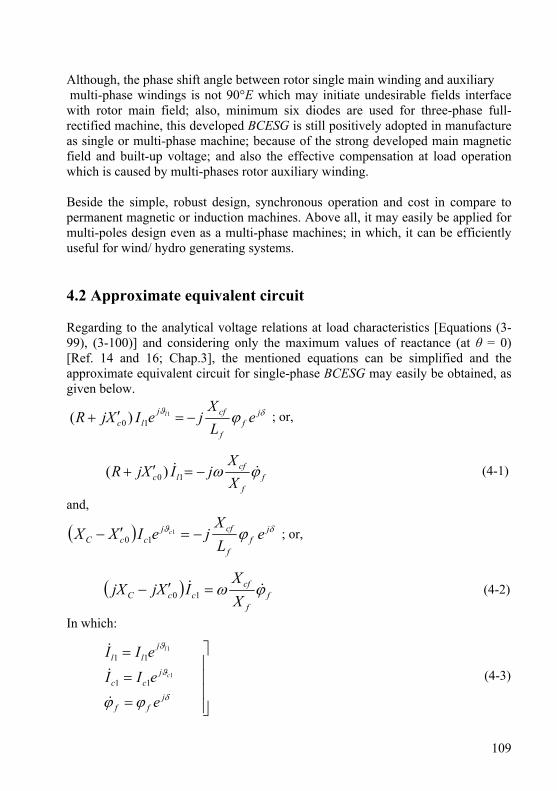
109
Although, the phase shift angle between rotor single main winding and auxiliary multi-phase windings is not 90°E which may initiate undesirable fields interface with rotor main field; also, minimum six diodes are used for three-phase full-rectified machine, this developed BCESG is still positively adopted in manufacture as single or multi-phase machine; because of the strong developed main magnetic field and built-up voltage; and also the effective compensation at load operation which is caused by multi-phases rotor auxiliary winding. Beside the simple, robust design, synchronous operation and cost in compare to permanent magnetic or induction machines. Above all, it may easily be applied for multi-poles design even as a multi-phase machines; in which, it can be efficiently useful for wind/ hydro generating systems. 4.2 Approximate equivalent circuit Regarding to the analytical voltage relations at load characteristics [Equations (3-99), (3-100)] and considering only the maximum values of reactance (at θ = 0) [Ref. 14 and 16; Chap.3], the mentioned equations can be simplified and the approximate equivalent circuit for single-phase BCESG may easily be obtained, as given below.
δϑ ϕ jf
f
cfjlc e
LX
jeIXjR l −=′+ 110 )( ; or,
ff
cflc X
XjIXjR ϕω && −=′+ 10 )( (4-1)
and,
( ) δϑ ϕ jf
f
cfjccC e
LX
jeIXX c −=′− 110 ; or,
( ) ff
cfccC X
XIXjjX ϕω && =′− 10 (4-2)
In which:
⎥⎥⎥⎥
⎦
⎤
=
=
=
δ
ϑ
ϑ
ϕϕ jff
jcc
jll
e
eII
eIIc
l
&
&
&
1
1
11
11
(4-3)
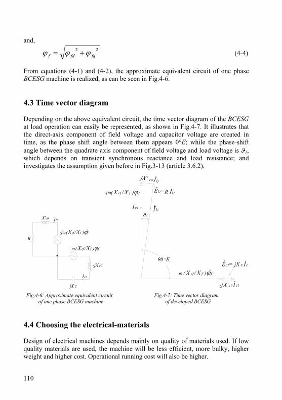
110
and, 22
fqfdf ϕϕϕ += (4-4) From equations (4-1) and (4-2), the approximate equivalent circuit of one phase BCESG machine is realized, as can be seen in Fig.4-6. 4.3 Time vector diagram Depending on the above equivalent circuit, the time vector diagram of the BCESG at load operation can easily be represented, as shown in Fig.4-7. It illustrates that the direct-axis component of field voltage and capacitor voltage are created in time, as the phase shift angle between them appears 0°E; while the phase-shift angle between the quadrate-axis component of field voltage and load voltage is ϑ1, which depends on transient synchronous reactance and load resistance; and investigates the assumption given before in Fig.3-13 (article 3.6.2).
R
Il1X'c0
-jω ( X cf/X f )ϕf
ω ( X cf/X f )ϕf
Ic1
jX C
-jX'c0
c0 I l1
El1=R Il1
I l1I c1
-jω( X cf / X f )ϕ f
ω ( X cf / X f )ϕ f
Ec1= jX C I c
-j X' c0 I c1
90 °E
ϑ1
Fig.4-6: Approximate equivalent circuit Fig.4-7: Time vector diagram of one phase BCESG machine of developed BCESG 4.4 Choosing the electrical-materials Design of electrical machines depends mainly on quality of materials used. If low quality materials are used, the machine will be less efficient, more bulky, higher weight and higher cost. Operational running cost will also be higher.
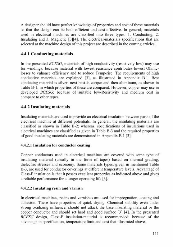
111
A designer should have perfect knowledge of properties and cost of these materials so that the design can be both efficient and cost-effective. In general, materials used in electrical machines are classified into three types: 1. Conducting; 2. Insulating and 3. Magnetic [3][4]. The electrical-materials specifications that are selected at the machine design of this project are described in the coming articles. 4.4.1 Conducting materials In the presented BCESG, materials of high conductivity (resistively low) may use for windings; because material with lowest resistance contributes lowest Ohmic-losses to enhance efficiency and to reduce Temp-rise. The requirements of high conductive materials are explained [3], as illustrated in Appendix B.1. Best conducing material is silver, next best is copper and then aluminum, as shown in Table B-1; in which properties of these are compared. However, copper may use in developed BCESG; because of suitable low-Resistivity and medium cost in compare to other types. 4.4.2 Insulating materials Insulating materials are used to provide an electrical insulation between parts of the electrical machine at different potentials. In general, the insulating materials are classified as shown in Table B-2; whereas, specifications of insulations used in electrical machines are classified as given in Table B-3 and the required properties of good insulating materials are demonstrated in Appendix B.1 [3]. 4.4.2.1 Insulation for conductor coating Copper conductors used in electrical machines are covered with some type of insulating material (usually in the form of tapes) based on thermal grading, dielectric stresses and economy. Same materials types, given in mentioned Table B-3, are used for conductor coverings at different temperature levels. Advantage of Class-F insulation is that it posses excellent properties as indicated above and gives a reliable performance for a longer operating life [3]. 4.4.2.2 Insulating resin and varnish In electrical machines, resins and varnishes are used for impregnation, coating and adhesion. These have properties of quick drying, Chemical stability even under strong oxidizing influence, should not attack the base insulating material or the copper conductor and should set hard and good surface [3] [4]. In the presented BCESG design, Class-F insulation-material is recommended; because of the advantage in specification, temperature limit and cost that illustrated above.
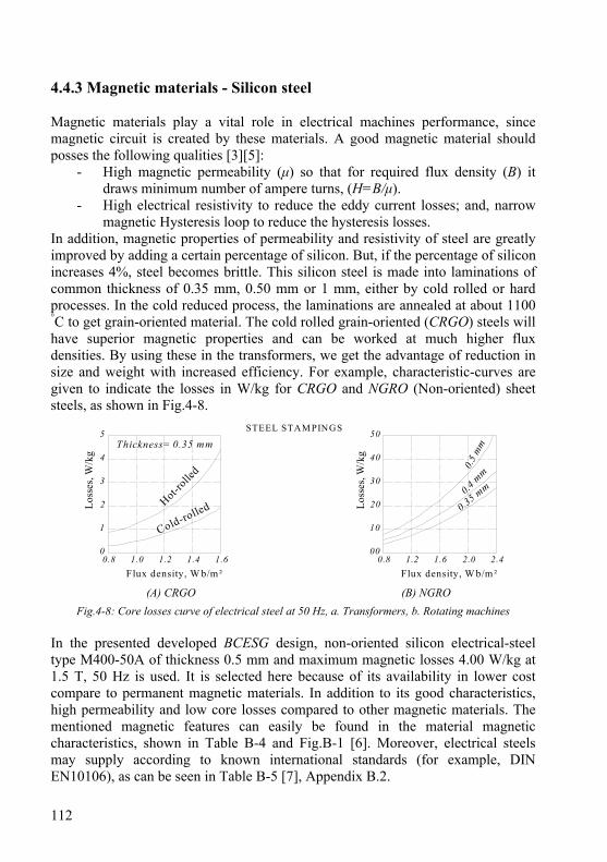
112
4.4.3 Magnetic materials - Silicon steel Magnetic materials play a vital role in electrical machines performance, since magnetic circuit is created by these materials. A good magnetic material should posses the following qualities [3][5]:
- High magnetic permeability (μ) so that for required flux density (B) it draws minimum number of ampere turns, (H=B/μ).
- High electrical resistivity to reduce the eddy current losses; and, narrow magnetic Hysteresis loop to reduce the hysteresis losses.
In addition, magnetic properties of permeability and resistivity of steel are greatly improved by adding a certain percentage of silicon. But, if the percentage of silicon increases 4%, steel becomes brittle. This silicon steel is made into laminations of common thickness of 0.35 mm, 0.50 mm or 1 mm, either by cold rolled or hard processes. In the cold reduced process, the laminations are annealed at about 1100 °C to get grain-oriented material. The cold rolled grain-oriented (CRGO) steels will have superior magnetic properties and can be worked at much higher flux densities. By using these in the transformers, we get the advantage of reduction in size and weight with increased efficiency. For example, characteristic-curves are given to indicate the losses in W/kg for CRGO and NGRO (Non-oriented) sheet steels, as shown in Fig.4-8.
0.8 1.0 1.2 1.4 1.60
1
2
3
4
5
0.8 1.2 1.6 2.0 2.400
10
20
30
40
50
Flux density, W b/m² Flux density, W b/m²
Hot-rolle
d
Loss
es, W
/kg
Loss
es, W
/kg
STEEL STAM PINGS
Cold-rolled
0.35 mm
0.35 mm0.4
mm
0.5
mm
Thickness=
(A) CRGO (B) NGRO
Fig.4-8: Core losses curve of electrical steel at 50 Hz, a. Transformers, b. Rotating machines In the presented developed BCESG design, non-oriented silicon electrical-steel type M400-50A of thickness 0.5 mm and maximum magnetic losses 4.00 W/kg at 1.5 T, 50 Hz is used. It is selected here because of its availability in lower cost compare to permanent magnetic materials. In addition to its good characteristics, high permeability and low core losses compared to other magnetic materials. The mentioned magnetic features can easily be found in the material magnetic characteristics, shown in Table B-4 and Fig.B-1 [6]. Moreover, electrical steels may supply according to known international standards (for example, DIN EN10106), as can be seen in Table B-5 [7], Appendix B.2.
113
4.5 Design procedure for BCESG Aim of design is to determine the dimensions of each part of the machine, prepare the drawings and furnish to manufacturing units after choosing the materials specifications. Design has to be carried out keeping in view the optimizing of the cost, volume and weight and at the same time achieving the desired performance as per specification [3]. The design procedure of the developed BCESG machine can be illustrated in the flowchart given in Fig.4-9. In addition a simple computer program may use to facilitate the theoretical calculations. In many literatures, however, there are basic input data for carrying out a design of any electrical machine [3][4][5], which are:
- The output rating in kW or in kilovolt-ampere with a given power factor. - Rated terminal voltage, rated frequency and rotational speed or number of
magnetic poles. - Number of phases and type of winding connection. - Type of cooling, medium temperature, temperature rise & insulation class. - International protection (IP) and any stipulations imposed by customer.
In absence of any input data, the same may be taken from relevant standard specifications. The complete design process and equations can be well illustrated in the following articles. 4.5.1 The machine active parts In A.C. rotating machines, the relation between the machine rating (S) and main dimensions can be represented by a formula called the machine output equation [4] [8], which is given below as:
so nLDCS 21= (4-5)
Where, S is the apparent power in kVA which equal to machine output at unity power factor. The volume of active parts of the machine is closely related to D1
2 L. D1 represents the inner diameter of the stator core and L represents the core length, which usually equal for stator and rotor. Since, ns is the synchronous rotational speed (in, r.p.s.), then the output coefficient (Co) is proportional to the rated torque per unit volume; and it can be given in terms of specific magnetic loading (Bav) and specific electrical loading (ac) [4][8], as the following:
31
2 10−×= acBKKC avwfo π (4-6)
In which:
Bav = Specific magnetic loading = gapairatpathfluxofAreagapairthearoundfluxTotal
−−
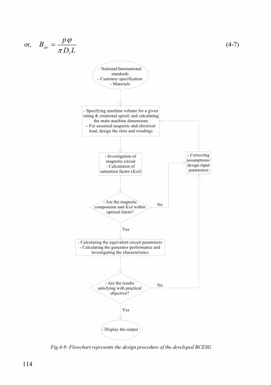
114
or, LD
pBav1πϕ
= (4-7)
- National/Internationalstandards
- Customer specification- Materials
- Specifying machine volume for a givenrating & rotational speed; and calculating
the main machine dimensions- For assumed magnetic and electrical
load, design the slots and windings
- Investigation ofmagnetic circuit- Calculation of
saturation factor (Ksd)
- Are the magneticcomponents and Ksd within
optimal limits?
Yes
No
- Correctingassumptions/design inputparameters
- Calculating the equivalent circuit parameters- Calculating the generator performance and
investigating the characteristics
- Are the resultssatisfying with practical
objective?
Yes
No
- Display the output
Fig.4-9: Flowchart represents the design procedure of the developed BCESG
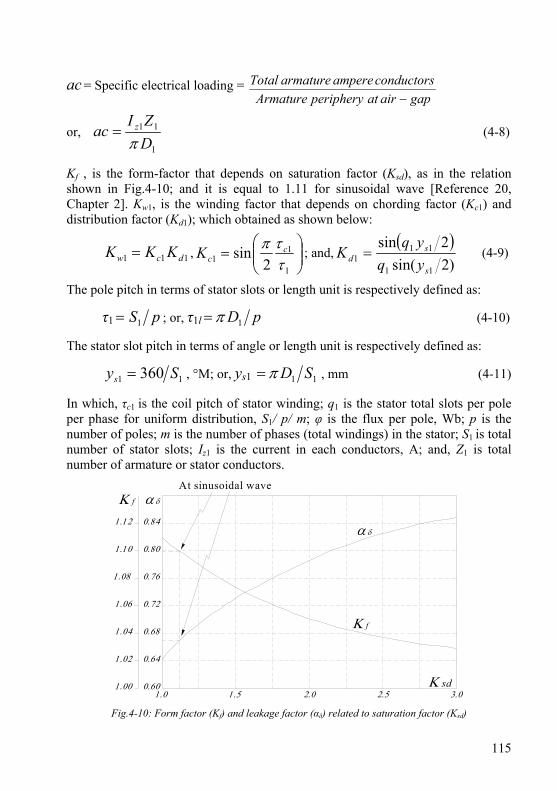
115
ac = Specific electrical loading = gapairatperipheryArmature
conductorsamperearmatureTotal−
or, 1
11
DZI
ac z
π= (4-8)
Kf , is the form-factor that depends on saturation factor (Ksd), as in the relation shown in Fig.4-10; and it is equal to 1.11 for sinusoidal wave [Reference 20, Chapter 2]. Kw1, is the winding factor that depends on chording factor (Kc1) and distribution factor (Kd1); which obtained as shown below:
111 dcw KKK = , ⎟⎟⎠
⎞⎜⎜⎝
⎛=
1
11 2
sinττπ c
cK ; and,( )
)2sin(2sin
11
111
s
sd yq
yqK = (4-9)
The pole pitch in terms of stator slots or length unit is respectively defined as:
τ1 pS1= ; or, τ1l pD1π= (4-10)
The stator slot pitch in terms of angle or length unit is respectively defined as:
11 360 Sys = , °M; or, ys1 11 SDπ= , mm (4-11)
In which, τc1 is the coil pitch of stator winding; q1 is the stator total slots per pole per phase for uniform distribution, S1/ p/ m; φ is the flux per pole, Wb; p is the number of poles; m is the number of phases (total windings) in the stator; S1 is total number of stator slots; Iz1 is the current in each conductors, A; and, Z1 is total number of armature or stator conductors.
α δΚ f
Κ f
α δ
Κ sd1.00
1.02
1.04
1.06
1.08
1.10
1.12
0.60
0.64
0.68
0.72
0.76
0.80
0.84
1.0 1.5 2.0 2.5 3.0
At sinusoidal wave
Fig.4-10: Form factor (Kf) and leakage factor (αδ) related to saturation factor (Ksd)

116
4.5.1.1 Importance of specific loadings The specific magnetic loading is determined by maximum flux density in iron parts of machine, magnetizing current and core losses; while, the specific electrical loading is determined by current density, applied voltage, size of machine and permissible temperature rise [4]. The advantages and disadvantages of selecting higher specific magnetic loading (Bav) and specific electrical loading (ac) are given in Table B-6 and Table B-7 Appendix B-3, respectively [3]. Considering the aspects given in the mentioned tables, the suitable values for specific loadings are selected for this project work, regarding to lower materials cost. Table 4-1 shows normal values of specific magnetic loading, specific electrical loading and current density for synchronous machines usually used in practice. These values are for a temperature rise 40 °C. For a temperature rise of 50 °C, the values given in Table 4-1 may be increased by 7.5% for Bav and 7.5% for ac, and 15% for J1 [4][9]. However J1 for the presented BCESG is taken in the range between 3 and 8 A/mm2, depending on the size of the machine.
Table 4-1: Recommended values of specific loadings for 3-phase, 50 Hz synchronous machines
Stator inner diameter
Ratio “maximum”
Specific magnetic loading
Specific electrical loading
Current density
D1 (m) L/D1
Bav (Wb/m2)
ac (A-conductors/m)
J1 (A/mm2)
0.20 0.70 0.40 13000 3.4 0.30 0.65 0.43 17500 3.3 0.40 0.62 0.46 21500 3.2 0.50 0.60 0.48 25000 3.2 0.75 0.50 0.52 35000 3.2 1.00 0.42 0.54 36000 3.2 1.50 0.33 0.55 37000 3.2 2.00 0.33 0.56 38000 3.2
Where: J1 = Iz1 / az1 (4-12) az1 = π (dc1/2)2 , is the effective cross-section area of the stator balanced windings. dc1 is the effective conductor diameter of stator winding. 4.5.1.2 Separation of stator core length and inner stator diameter As mentioned above, the synchronous machine effective volume (D1
2 L) can be calculated using equation 4-5. The next step is to split this volume up into its component D1 and L. In large alternators, the diameter is limited by the maximum allowable peripheral speed (np = π D1 ns).
117
Since rotor salient poles of BCESG machines are considered of rectangular poles type, the ratio of core length to pole pitch length (L/τ1l) is varied in the range between 1 and 3. The rotor peripheral speed and moment of inertia increase as the diameter is increased. In small alternators, the diameter is determined by the number of poles to ensure that the pole pitch is sufficiently large so that the field coils can be accommodated; where, the volume of copper is minimum when the field coils cross-section is approximately a square. Hence L/τ1l of between 0.8 and 1.2 yields satisfactory designs in small ratings machines till 30 kVA [8]. 4.5.2 Air-gap length and the importance of SNSP rotor construction The length of air-gap greatly influences the performance of a synchronous machine. In general, a machine with a large air-gap (a high value of short-circuit ratio, SCR and consequently with a small value of synchronous reactance, XD) has a small value of inherent regulation, a higher value of stability limit and a higher synchronous power which makes the machine less sensitive to load variations [4]. In addition has better cooling at the gap surface, lower tooth pulsation losses, lower noise level and a smaller unbalanced magnetic pull. Where XD is per-unit direct-axis synchronous reactance; and SCR is the short circuit ratio that is defined for synchronous machines as the ratio of field current required to produce rated voltage at open circuit to field current required to circulate rated current at short circuit. It can also be defined as, SCR = 1 / XD . Therefore, the rotor of BCESG is designed in two active gaps which are combined between salient and non-salient pole structure. This rotor (called SNSP) can be shown in general configuration at Fig.4-11; which is made in combination of salient and cylindrical rotor constructions. For salient-pole part, a large air-gap offers a large reluctance to the path of flux produced by armature MMF and thus reduces the negative effects of load armature reaction on main rotor field. While, the uniform narrow air-gap is facing the distributed auxiliary windings, those are embedded in non-salient rotor part to get use of load armature-reaction MMF for compensating the main magnetic field and producing a suitable voltage regulation. In literatures [4][10][11], the air-gap length at the center of the pole (lg) is derived from the no-load field MMF per pole (ATf0) of synchronous generators, either for hydroelectric/ wind generator (salient-pole rotor) or turbo-generators (cylindrical rotor), as given below.
6060 1010 −− ×=×=gg
f
gav
ffg KB
ATKB
ATKl , in m (4-13)
Where:
118
favg KBB /= , is the maximum air-gap flux density, in Wb/m2 or Tesla; and,
SCRp
KTIAT wllf ×= 111
07.2 , for salient-pole rotor (4-14)
or, SCRacATf ×=2
10
τ, for cylindrical-pole rotor (4-15)
In the above relations Il1 is the rated phase armature current (load current); and Tl1 is the number of turns per phase per path of load winding (Wl). Kg is defined as the gap contraction factor and is taken as 1.1 for all practical purposes [4]. The value of SCR for salient-pole hydroelectric/ wind generators is normally between 1.0 and 1.5, and varies from 0.5 to 0.7 for modern turbo-generators. Hence, lg depend on assumption given for Kg and SCR. Roughly estimation for the ratio of air-gap length to pole pitch length (lg/τ1l) for standard synchronous generators can be achieved, as in the following [4].
- For salient-pole machines of normal construction, having open type slots: lg /τ1l = 0.010 to 0.015
- For turbo-alternators, with massive rotors: lg /τ1l = 0.020 to 0.025 In BCESG, there are two types of air-gap, one is a uniform length narrow air-gap (lg1) at direct axis of main rotor pole to fully utilize from the armature-reaction magnetic field in inducing the required compensating EMF; and the second is non-uniform large air-gap (lg2) which is facing the quadrate-axis of main pole to reduce the effect of armature reaction on main rotor field windings, as shown in the general machine construction at the mentioned Fig.4-11. Because the BCESG machine is of combined construction, its features is combined between the characteristics of salient and non-salient rotor poles machines and so it can be designed for two/four poles in same manner as for multi-poles machine. By assuming that 80% of no-load MMF to be lost in the air-gap, then the range of ratio is estimated here with some corrections as: lg /τ1l = 0.010 to 0.020. In addition, it is recommended in this presented design to take a ratio near 0.01 for low size and/or 2 to 4 poles machines; while, for large size and/or multi-pole machines, the recommended ratio is considered near 0.02. Finally, lg2 is recognized later after designing the rotor stamp. 4.5.3 Rotor inner diameter and stator outer diameter The rotor inner diameter or the shaft diameter (dsh) is very important parameter because it must satisfy the mechanical and electromagnetic considerations, as standing the weight, bending, stress and oxidization [12]; and also keeps sufficient

119
height of rotor core and pole-body width for suitable core flux density (Bh2), as will be discussed in magnetic circuit, later. Therefore, dsh is given in literatures as a formula that depends on rotor weight (G2) and distance between bearings (Lb) [13]. Because of two air-gap lengths in this design project case, dsh equation can be modified, as shown below.
( )[ ] 25.0
213
23 2105 ggbsh llLGd +×= − (4-16)
Where: G2 is the total weight of rotor steel core and rotor copper windings (neglecting insulations). Lb is determined depending on rotor end-winding length and if the rotating rectifier group is assembled on shaft inside the housing frame or from outside; also depends upon, if the fan system is internally or externally adjusted. However, dsh should not be lower than the diameter of machine end-drive, which is normally given within standard dimensions that based on machine size and ratings (for example NEMA, IEC or DIN standards). In addition, the mechanical standard dimensions of bearings are also considerable in calculating dsh. From other hand, the stator outer diameter (Do) is given as:
)(2 11 hhDD so ++= (4-17) In which: hs is the height of stator-slot and it is obtained later depending on the slot shape. h1 is the height of stator-core and can be calculated from the following equation, after assuming a suitable value for stator core flux density (Bh1).
Efeh KKBLh
11 2
ϕ= (4-18)
φ is the flux per pole and Bh1 is stator-core flux density for salient-pole machines, recommended between 1.4 and 1.8 Wb/m2 [4]. The same range is taken for BCESG machine. Kfe is the stacking factor, normally given 0.95. KE is the voltage-drop reduction factor due to resistance and leakage reactance and it can be assumed between 0.85 and 0.98; the high value refers to lower number of poles. Fig.4-11 shows the general construction of BCESG with main design dimensions. 4.5.4 Slot design Here, the number of slots and its construction in stator and rotor of BCESG are discussed. Whereas design of stator slots are conventional, as in slot design of common A.C. machines [4][5][8], the design of slots of SNSP rotor is combined between cylindrical and salient pole slot construction, as illustrated below.
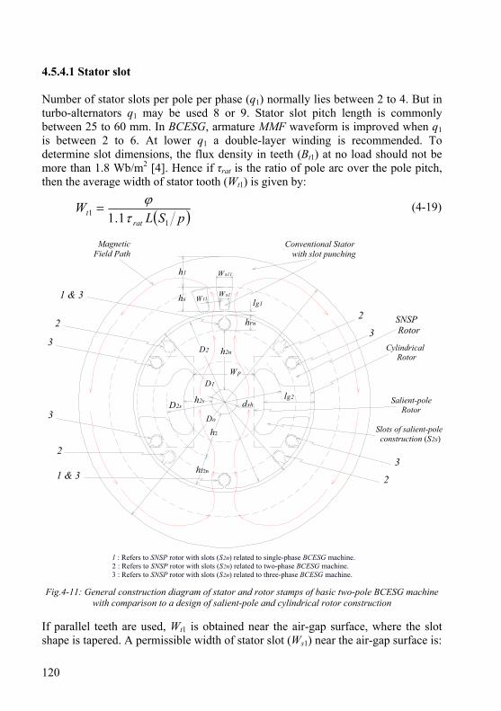
120
4.5.4.1 Stator slot Number of stator slots per pole per phase (q1) normally lies between 2 to 4. But in turbo-alternators q1 may be used 8 or 9. Stator slot pitch length is commonly between 25 to 60 mm. In BCESG, armature MMF waveform is improved when q1 is between 2 to 6. At lower q1 a double-layer winding is recommended. To determine slot dimensions, the flux density in teeth (Bt1) at no load should not be more than 1.8 Wb/m2 [4]. Hence if τrat is the ratio of pole arc over the pole pitch, then the average width of stator tooth (Wt1) is given by:
( )pSLW
ratt
11 1.1 τ
ϕ= (4-19)
SNSP Rotor
Conventional Stator with slot punching
Cylindrical Rotor
Salient-pole Rotor
2
3
lg1
h2s
3
3
3
1 & 3 2
2
1 & 3
2
hs
h1
dshD2s
h2n
Do
D2
D1
hrn
1 : Refers to SNSP rotor with slots (S2n) related to single-phase BCESG machine.2 : Refers to SNSP rotor with slots (S2n) related to two-phase BCESG machine.3 : Refers to SNSP rotor with slots (S2n) related to three-phase BCESG machine.
Slots of salient-pole construction (S2s)
Ws1W t1
lg2
W s11
MagneticField Path
W p
h2
ht2n
Fig.4-11: General construction diagram of stator and rotor stamps of basic two-pole BCESG machine with comparison to a design of salient-pole and cylindrical rotor construction
If parallel teeth are used, Wt1 is obtained near the air-gap surface, where the slot shape is tapered. A permissible width of stator slot (Ws1) near the air-gap surface is:

121
( ) 1111 ts WSDW −= π (4-20)
As shown in Fig.4-11, the depth or height of stator slot (hs) preferably should not exceed three (or 2.5 to 3) times the width (Ws1). Deeper slots may be used and sometimes slots are deliberately made deeper in order to have a high leakage reactance which limits short circuit currents. 4.5.4.2 Rotor slots In SNSP rotor construction, two types of rotor slots are existed. 1st type is the slots punching (named, slots type-S2n) embedded in the non-salient part, the 2nd type is the slots of salient-pole construction (named, slots type-S2s) as can be illustrated in Fig.4-12, below. The design of both rotor slots groups is discussed as following.
dsh
h2nD2
hrn
45° 60°
120°
90°
hrs
h2s
1 & 3
2
3
3
2
S2sS2n
S2n
S2n
S2n
S2nho2n wo2n
do2n
W rs
90°
Direct-axis lineof salient pole
Center-line of S2s
h2ss
W 2s
W 2ss
Fig.4-12: SNSP rotor with slots for 1-phase (S2n , group 1), 2-phase (S2n , group 2) & 3-phase (S2n , group 3) BCESG
122
- First slots type-S2n: For simplicity in implementation and for using conductors of round cross sectional area, S2n is recommended to be of common trapezoidal or circular semi-closed shape, as shown in Fig.4-12. Whereas, a design of rectangular open slot shape is recommended for conductors of rectangular cross sectional area. This slots group (S2n) is symmetrically distributed at the periphery of SNSP rotor stamp as in common cylindrical rotor types. The distribution begins at angle relative to any direct-axis line of rotor salient pole. In other words, the symmetrical rotor slots (S2n, group 1) distribution for single-phase BCESG machine starts in alignment to salient-pole direct-axis, i.e. the relative shifting angle is 0°E, as shown in Fig.4-11 and Fig.4-12. The same phase-shift alignment (0°E) is valid for rotor slots distribution (S2n, group 3) of three-phase machine. While the relative shifting angle is 45° for starting the rotor slots distribution (S2n, group 2) of two-phase BCESG machine as shown in the same mentioned above figures. The rotor auxiliary winding which has the function of compensating the main magnetic field is occupied in the mentioned rotor slots (S2n); though it is not much important here to distribute the windings in many rotor slots per pole per phase as in the case of better armature MMF waveform, and therefore S2n is recommended to be taken as just one or two slots per pole per phase. The slot-opening width (wo2n) is taken approximately in a range between 2 to 2.5 times of effective-conductor diameter (dc2) of rotor winding. The height of slot-opening (ho2n) is preferred less than 0.5 wo2n , proportional to machine size. The slot area (As2n, without insulations) can simply be specified by a suitable bare-slot fullness factor (Ks2n), which is here considered between 0.2 and 0.5, Thus:
π×⎟⎠⎞
⎜⎝⎛==
22
2
222 2
no
ns
ncncns
dK
NAA (4-21)
In which: do2n , is the diameter of circular-construction of slot type-S2n , as shown in Fig.4-12, above. Ac2n = π (dc2n/2)2, is the cross sectional area of effective conductor of rotor auxiliary winding (Wra). Nc2n , is the number of effective conductors per slot, type-S2n and it’s determined as following. dc2n , is the diameter of the effective conductor of winding Wra.
( ) ( )nranrapnc qpTalTN 2222 2=×= (4-22)
Where: Trap is the number of turns per pole per phase, and l2n is number of layers of rotor auxiliary winding (Wra). a2 is the parallel current path, q2n is number of slots per pole per phase and Tra is the number of turns per phase of same winding Wra.
123
The over all depth (hrn) of slot S2n is given by: hrn ≈ do2n + ho2n ; Thus, the maximum height of rotor core (h2n), under hrn (referred to Fig.4-11) is:
( )rnshn hdDh 25.0 22 −−= (4-23) - Second slots type-S2s: The 2nd type of rotor slots (S2s) is of hollow shape (approximately trapezoidal) constructed at both sides of each salient-pole type of SNSP rotor and occupied with concentric main rotor coils. The same structure is applied even if the BCESG machine is single-, two- or three-phase. The center-line of S2s is aligned at 90°E shift-angle from direct-axis line of each salient pole, as shown in Fig.4-12. The dimensions of rotor slot type-S2s may depend on the ratio of pole-arc (Parc) to rotor pole-pitch (τ2), τrat = Parc /τ2 and the minimum height of rotor core (h2s). The ratio τrat relies on insuring a suitable path of magnetic field to both salient- and non-salient rotor poles; hence it increases as the number of phases increase. However, τrat is preferred here in a range between 0.7 and 0.9 in such a way to satisfy the following conditions, where the pole-arc ratio in the conventional salient-pole synchronous machines is different, normally 0.67.
( ) 2τ≈+ rsarc WP ; and, ⎥⎦
⎤⎢⎣
⎡−
−≤ no
n
nors d
SdDW 22
22 )(4.0 π (4-24)
In which, the peripheral length of rotor pole pitch is:
pD /22 πτ = (4-25)
If the minimum width of rotor pole (for total path of magnetic flux at direct axis) is Wp (so called, pole-body width as shown in Fig.4-11) and by assuming a suitable flux density (Bh2) of rotor core at this part (between 1.2 to 1.6 Wb/m2), the core height (h2s) under slot S2s can then be assumed in a limited range that satisfy the following: 0.75 Wp < h2s ≤ Wp ; where,
( )fehp KBLW 2ϕ= (4-26)
Now the depth (hrs) of slot type-S2s can be determined, as:
( )sshrs hdDh 22 25.0 −−= (4-27)
The geometrical shape of slots type-S2s is near to trapezoidal with two bases (W2s, W2ss) and height (h2ss), as shown in Fig.4-12. By neglecting the curvature chamfers, the shorter base length (W2s) can be obtained by the following equation,
( )[ ] psshs WphdW −+= 22 2π (4-28)

124
Then the surface area (As2s) of slot type-S2s is:
( )sssssss WWhA 2222 5.0 += (4-29)
By using the above equation, the relations between dimensions of the trapezoidal slot can geometrically be solved to give the following:
( )( )( ) ( ) ⎪⎭
⎪⎬⎫
⎥⎦⎤
⎢⎣⎡ ++−=
+=
ssssssssss
sssssss
hWAhWWWh
hhhWW
222222
222
22222
//2
/ (4-30)
After rotor main winding is wounded, the above relation may achieve a suitable bare-slot fullness factor (Ks2s) for rotor slots type-S2s, between 0.2 and 0.45, where:
ssscscss ANAK 2222 = (4-31)
Where, Ac2s = π (dc2s/2)2, is the cross sectional area of effective conductor of rotor main winding (Wrm). Nc2s , is the number of effective conductors per slot. As2s is a rotor slot area, type-S2s without insulations; and, dc2s is the diameter of the effective conductor of winding Wrm. Mechanically, a suitable curvature chamfer at the edge-end of designed dimensions is generally applied to protect the slot insulations from mechanical stress or distortion and to decrease the concentration of flux densities at edges and corners of the rotor and stator constructions. 4.5.5 Windings design The developed BCESG is occupied by four groups of windings. Two windings are distributed at stator core as a load winding and exciter winding. The other two windings are wound in the rotor core as a field and auxiliary windings, as illustrated previously in chapter two. All the windings, except the field winding, can be distributed as lap, wave or concentric type with double or single layer. The distribution of winding turns and chording may affect to illuminate the harmonics; the field winding is made of concentric turns coils. However, all the distributed windings are of multi-turn coils which have the following advantages [4]:
- Allow greater flexibility in selecting the value of stator slots to give a required number of turns per phase.
- Since the multi-turns coils are machine made, they are cheaper than the hand made coil of a bar winding.
The winding design for synchronous machines is generally discussed in literatures [3] [4] [5] [9] [14]; however, the specific design of windings for the presented machine is determined here, as explained in the following articles.
125
4.5.5.1 Stator load winding The stator load winding (Wl) or armature winding of BCESG can be selected for single, two or three phase winding design. The advantages of balanced two-phase and three-phase windings is that the windings has to be insulated to earth for the phase voltage and not the line voltage. Balanced star connection also has the advantage that it eliminates all triple frequency harmonics from the line voltage [4]. Also, the coil pitch is so chosen that the highest amplitude harmonics (likely to be 5th and 7th) in the flux distribution curve are drastically reduced. The maximum reduction of these harmonics is given by a chorded coil pitch of 8.33% of pole pitch. Therefore, the coil pitch is chosen where ratio of number of slots to number of poles does permit it, otherwise the coil pitch used should be as near to this value as possible. The load winding is designed after assuming a specific magnetic loading (Bav), specific electrical loading (ac), suitable winding factor (Kw1) and saturation factor (Ksd) above to the determination of machine main dimensions, as explained below. First a suitable ratio of τrat is selected; then the maximum air-gap flux density (Bg) over pole arc is determined as:
ratavg BB τ= (4-32)
From Fig.4-10, by assigning the leakage factor (αδ) for a given saturation factor, the air-gap flux per pole (φ) can be determined, as in the following equation:
gl BL1ταϕ δ= (4-33)
Referring to equation (4-9), the stator winding factor Kw1 can be calculated and substituted now in the general voltage equation to determine the winding turns per phase (Tl1) as given below,
( )ϕ111 4 wfll KfKET = (4-34)
In which: f is the generator output frequency; Kf is the form factor as mentioned before; which is determined from Fig.4-10 corresponding to a given saturation factor Ksd; El1 = (Vl /KE) is the induced armature EMF per phase for load winding circuit; and, Vl is the generator rated output voltage. Dividing the numerator and denominator of equation (4-8) over total slots number yields:
111 ssz yZIac = (4-35)
Where conductor-current in each of stator windings is:
c
c
l
lz a
IVma
SaII
1
1
111
11 === (4-36)
126
Zs1 is number of effective conductors per stator slot. It is determined similar to equation (4-22), as:
pqTa
pqTa
SZZ ccl
s1
11
1
11
1
11
22=== (4-37)
Il1 , Ic1 are the values of phase current in Wl and Wc windings, respectively; a1 , a1c are the number of parallel current paths in stator load and capacitor windings, respectively. Whereas, Tc1 and Tl1 are defined as the number of turns per phase per single path of windings Wc and Wl, respectively. 4.5.5.2 Stator capacitor-exciter winding The stator capacitor-exciter winding (Wc) is one phase distributed winding that occupied in the slots of stator core together with load winding (Wl). For better performance, it is considerable to have a sinusoidal MMF wave for Wc with minimum harmonics. To obtain that a suitable chording and graduated or fractional slots distribution is required for Wc. Therefore, it is appreciated to design balanced Wc and Wl windings in a single phase BCESG; however, in multi-phase design, third to two-third slots for respective windings distribution is recommended. To determine the effective turns-ratio (ar), the following relation is used:
111 lwcwcr TKTKa = (4-38)
Later, the parallel path number for Wc winding is assigned to insure an equal number of effective conductors per slot for each stator slot. In the above relation, if the distribution of stator windings are of gradual type then the winding factor Kwc and Kw1 are different in values and determined separately, otherwise Kwc= Kw1. For investigation, the stator bare-slot fullness factor (Ks1) is calculated, which suppose to be the same in each stator slot, filled with Wl or Wc windings. For good design, Ks1 value is given within the range between 0.35 and 0.45, and it is calculated as shown below:
1111 sszs AZaK = (4-39)
In which, az1 is the effective cross-section area of the conductor of stator windings; and, As1 is the total area of one stator slot without insulations. 4.5.5.3 Rotor main field winding In order to design the main field winding (Wrm) of the presented BCESG, it is necessary to estimate the field ampere-turns required to overcome armature MMF.
127
Wrm in the case of synchronous machines is of “single phase” type and carries mainly D.C. excitation component. The self-excitation is started even at no-load operation. The armature MMF of single phase capacitor-exciter winding (Wc) may equate and interact with the MMF of rotor main field (ATf) due to a narrow air-gap length facing the rotor salient-pole part at direct-axis of SNSP construction. For this case, the amplitude of fundamental MMF (ATc) of one phase winding per pole is [4]:
pKTIAT wccc
c1124
π= (4-40)
Since the capacitor is parallel connected across stator winding Wc , then the machine operates at zero leading power factor and the armature MMF ATc acts only on the direct axis; i.e., it has no quadrate axis component [4]; thus the above equation can be written again for direct axis as:
11111 sin8.124 ψ
π pKTI
pKTIAT wcccwccdc
cd == (4-41)
Where: Ic1d is the armature current component causing the direct axis armature MMF, and it is given by:
111 sinψcdc II = ; and, 111 δφψ += (4-42)
Also, 1φ is the power factor angle; and, δ1 is the load angle. At zero power factor,
=1φ 90°, therefore no active power is delivered and hence δ1 = 0°, thus ψ1 = 90° and, sin ψ1 = 1 . For this case the equivalent armature MMF for self-excitation in BCESG machine is realized from equation (4-41), as following:
( ) cwccccd ATpKTIAT == 118.1 (4-43)
But, the distribution of gap density at salient-pole part of SNSP rotor is estimated sinusoidal, as shown in Fig.4-13A [5]; and the rotor main field coils are concentrated, beside the length of air-gap is not uniform over the pole pitch; then the method, above, of equating MMF is not valid only after multiplying ATcd by a reduction factor in order to obtain the equivalent ATf . So that:
( ) 111 sin8.1 ψρ pKTIAT dwcccf = (4-44)
In which, ρd is the reduction factor for the direct-axis MMF and is calculated from the following equation, that relates to the angle of pole arc (αp) [4], in radians. Where, [αp
° E = (Parc/ τ2) ×180 ° E] is also denoted in other literatures as the direct-axis reaction factor (Kad) [5]
128
)2(sin4sin
P
Ppd α
ααρ
+= (4-45)
The field current Irm that flows in one coil of rotor salient-pole (or in rotor field winding Wrm with series current path) which is required to overcome ATcd at capacitor current Ic1, can be obtained as follow
rmpfsrm TATaI 2= (4-46)
Where: Trmp = Nc2s /2, is the number of turns per one pole (concentric coil) of rotor main field winding (Wrm); and, Nc2s is the number of conductors of Wrm winding per one rotor slot, type-S2s, as already defined; and, a2s , is the number of parallel paths for winding Wrm . 4.5.5.4 Rotor auxiliary winding The rotor auxiliary winding (Wra) is embedded in the non-salient (cylindrical) part of SNSP rotor. The task of Wra is to compensate the rotor magnetic field against armature reactive effect at load operation. In this case, the MMF of rotor auxiliary winding (ATfa) may equate the armature MMF per phase (ATl) of load winding. In cylindrical rotor machines, the field winding is distributed in slots and hence the gab flux density has a trapezoidal or rectangular distribution, as shown in Fig.4-13B [5]. Then, the armature MMF per phase at load operation can be expressed by:
pKTIAT wll
l11124
π= (4-47)
The above rectangular distributed single phase armature MMF is pulsating in amplitude, hence it can be resolved into two rotating-field components, one called the synchronous MMF and the other inverse MMF (negative sequence field) which is the effective one; each having half the magnitude as above. Beside that, the load can be of mixed inductive-resistive load. Hence, similar to derivation in article 4.5.5.3, above; and because of load winding Wl is located perpendicular (expect in double-phase BCESG), it suffices to equate the fundamental of rotor auxiliary field with a resolved component of armature M.M.F of load winding at load current of synchronous machines BCESG to obtain the following relation:
( ) 1111 sin9.0 ψpKTIAT wllfa = (4-48)
Therefore, the rotor auxiliary current Ira that is required in the coils of rotor winding Wra , of Trap turns per pole per phase, to compensate the rotor field of BCESG at rated load can be expressed as:
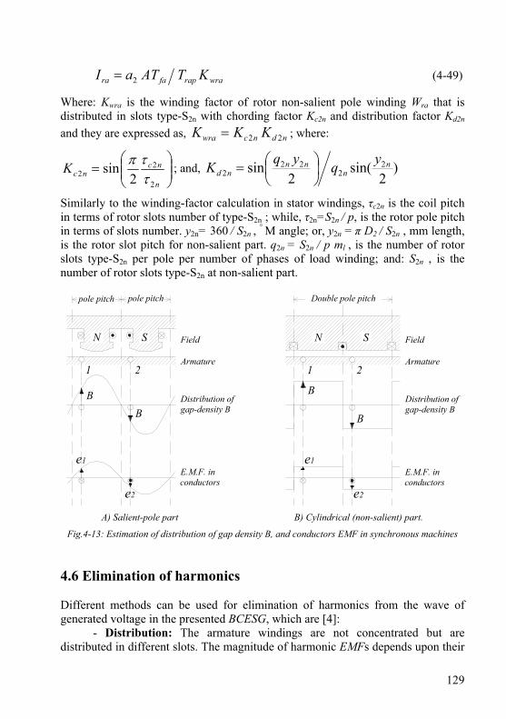
129
wrarapfara KTATaI 2= (4-49)
Where: Kwra is the winding factor of rotor non-salient pole winding Wra that is distributed in slots type-S2n with chording factor Kc2n and distribution factor Kd2n and they are expressed as, ndncwra KKK 22= ; where:
⎟⎟⎠
⎞⎜⎜⎝
⎛=
n
ncncK
2
22 2
sinττπ
; and, )2
sin(2
sin 22
222
nn
nnnd
yqyqK ⎟⎠⎞
⎜⎝⎛=
Similarly to the winding-factor calculation in stator windings, τc2n is the coil pitch in terms of rotor slots number of type-S2n ; while, τ2n=S2n / p, is the rotor pole pitch in terms of slots number. y2n= 360 / S2n , ° M angle; or, y2n = π D2 / S2n , mm length, is the rotor slot pitch for non-salient part. q2n = S2n / p ml , is the number of rotor slots type-S2n per pole per number of phases of load winding; and: S2n , is the number of rotor slots type-S2n at non-salient part.
Double pole pitchpole pitchpole pitch
N S N S
1 2 1 2
BB
B
B
e1
e2
e1
e2
Field
Armature
Distribution ofgap-density B
E.M.F. inconductors
Field
Armature
Distribution ofgap-density B
E.M.F. inconductors
A) Salient-pole part B) Cylindrical (non-salient) part.
Fig.4-13: Estimation of distribution of gap density B, and conductors EMF in synchronous machines 4.6 Elimination of harmonics Different methods can be used for elimination of harmonics from the wave of generated voltage in the presented BCESG, which are [4]:
- Distribution: The armature windings are not concentrated but are distributed in different slots. The magnitude of harmonic EMFs depends upon their
130
distribution factor (Kd) of load and capacitor-exciter windings. Kd for harmonics being small as compared with that of the fundamental and, therefore, the relative magnitude of harmonics EMFs is small.
- Chording: In short pitched coils, the EMFs generated in the two coils do not add algebraically. The generated EMF is proportional to cos(π αc /2); where αc is the angle of chording. The harmonics can then considerably be reduced or entirely eliminated by choosing proper αc value.
- Skewing: The slot harmonics can be eliminated by skewing SNSP rotor and the pole face.
- Fractional slot windings: The slot harmonic EMFs can be drastically reduced and even completely eliminated from the output voltage waveform by using fractional slot windings.
- Large length of air-gap: If a large air-gap length is used, the reluctance is increased and therefore the magnitude of slot harmonics is reduced. The flux pulsations can be reduced by having the number of slots per pole arc as an integer plus “1/2”. 4.7 Magnetic circuit of BCESG The study of magnetic circuit of BCESG machine is of significant importance to investigate the machine saturation factor (Ksd) and according to it correct the designed dimensions. The flux density of the magnetic core parts is calculated and the corresponding magneto-motive force is determined from the B-H curve of selected electrical steel characteristics. Later Ksd is calculated again and compared with the assumed one; then necessary changes may be added till the calculated saturation factor nearly matches the assumed one, as illustrated in coming articles. 4.7.1 The magnetic flux density (B) In this section, B per pole is determined at the effective parts of the magnetic circuit of developed BCESG machine. These are divided into B of air gap, B of teeth and B of core. 4.7.1.1 B at the air-gap By assuming suitable saturation factor (preferred between 1.3 and 1.5), corresponding form factor (Kf) and leakage factor (αδ) are determined from Fig.4-10. Then for specific magnetic load (Bav), the maximum air-gap flux density (Bg) over pole arc is determined from equation (4-32). In some literatures, Bg is recommended in between 0.4 and 0.6 Wb/m2 [3][4][5]. However, the assumption of Bg may differ according to number of poles and machine size or ratings.
131
4.7.1.2 B of the stator and rotor teeth The maximum flux density at stator tooth (Bt1) is assumed between 1.7 to 1.8 Wb/m2 , as mentioned in article 4.5.4.1; and it can be determined now from the following equation:
( )fetsgt KWyBB 111 = (4-50)
In which: Kfe is the stacking factor of core laminations and it’s give in the specifications of electrical steel or normally taken 0.97. Where the stator slot pitch length (ys1) and Stator tooth width (Wt1) are given from equations (4-11) and (4-19), respectively, as previously explained. While the maximum flux density of rotor teeth (Bt2) is obtained at teeth of non-salient rotor slots (type-S2n) part, so it can be assumed less than 1.4 Wb/m2; and it is calculated as in the following:
( )fentngt KWyBB 222 = (4-51)
Where, y2n is the rotor slot pitch length, referring to article 4.5.5.4 and definition of equation (4-49); and Wt2n is the average active width between two adjacent sides of slots type-S2n and is given as shown bellow.
( )[ ] rsnonnonont WdSdhDW −−−−= 222222 2π (4-52)
In which, do2n is the diameter of rotor slot type-S2n as shown in Fig.4-12, and it is in general the width of the slot type-S2n . 4.7.1.3 B of the stator and rotor core As explained in article 4.5.3, the recommended value of flux density Bh1 in stator core (yoke) is selected in between “1.4 to 1.8” Wb/m2 and it can empirically be given as:
( )Efeh KKhLB 11 2ϕ= (4-53)
In which:
( )[ ]so hDDh 25.0 11 +−= (4-54)
In similar manner, the rotor yoke or pole-body flux density (Bh2) is preferably given in between “1.2 to 1.6” Wb/m2, as already mentioned. It is computed at the cross section area of rotor yoke which is specified by core length (L) and rotor-pole minimum neck width (Wp, Fig.4-11) as represented in the following empirical formula, which is rearranged from equation (4-26), above.
( )feph KWLB ϕ=2 (4-55)
132
It is considerable to mention here that the resultant flux per pole (φ) is generally created by both direct-axis and quadrate-axis flux components (φfd and φfq), and hence it can be represented as in the following formula:
22fqfd ϕϕϕ += (4-56)
4.7.2 Magneto-motive force (AT) After determining the flux density of each magnetic part of the BCESG machine, the magneto-motive force can be obtained. Generally AT is calculated by multiplying the field strength (related to specific flux density value) by the related magnetic path length, referring to estimated resultant magnetic-field path that is illustrated in Fig.4-11. Hence AT is classified into three parts, as described below. 4.7.2.1 AT in the air-gap The maximum magneto-motive force (ATg) at minimum air-gap length (lg1, Fig.4-11) is:
( ) 01 μgggg BlKAT = (4-57)
Where μ0 is the permeability of free space and it is equal to 4π × 10-7. 4.7.2.2 AT at the stator and rotor teeth The corresponding field strength at stator and rotor teeth (Ht1 and Ht2) are first considered by the B-H curve referring to respective Bt1 and Bt2, then respective magneto-motive forces (ATt1 and ATt2) are calculated by the following equations:
stt hHAT 11 = (4-58)
nttt hHAT 222 = (4-59)
In which, ( )[ ] 2/2 222 hdDh shnt +−= , is rotor-tooth height, and also considered as the pole-shoe height. 4.7.2.3 AT of the stator and rotor core The required AT for yoke length per pole at stator and rotor cores (ATh1 and ATh2) can empirically be computed, as given in the following [14] [15].
1111 KHAT hhh τ= (4-60)
2222 KHAT hhh τ= (4-61)
133
In which: Hh1 , Hh2 : are the magnetic field strength at stator and rotor yoke in A/m, respectively; and they are assigned from B-H curve of the electrical steel in correspond to a given flux density. τh1 , τh2 : are the magnetic pole pitch length at stator and rotor yoke, respectively; and they can be obtained from the following equations which are based on the designed dimensions, that illustrated in Fig.(4-13) and Fig.(4-14), above.
pDoh πτ =1 (4-62)
( ) phdshh 22 2+= πτ (4-63)
Where: h2 = h2s + h2ss, is magnetic-path length in rotor yoke; also considered as pole-body height; K1 and K2 are the correction factors of ATh1 and ATh2, respectively. These empirical factors are inserted because the magnetic flux path is assumed in nearly the middle of the stator and rotor yoke lengths not on the peripherals. However, these are determined by:
21 )(4.0
1 89.0 hBeK −= (4-64) 2
2 )(4.02 89.0 hBeK −= (4-65)
4.7.3 The saturation factor and magnetization current The magnetic saturation factor (Ksd) is very important to investigate the machine dimensions and magnetic circuit. Its value also offers a primarily estimation of the electrical machine operation and performance, where Ksd preferable value for induction rotating machines is between 1.3 and 1.5 [15]. Since the operation of the presented developed BCESG is based on induction phenomena, then the same assumption can be obtained here. Ksd can also be calculated; where it is the ratio of total ampere-turns of active parts of the machine over the ampere-turns at the air-gap [3] [16] [17]. Since empirical equations and assumptions are used here, then Ksd is however obtained by the ratio of summations of air-gap and teeth ampere-turns over the air-gap ampere-turns, as shown below [15]:
( ) gttgsd ATATATATK 21 ++= (4-66)
Based on the calculated value of Ksd , corresponding values for form factor and leakage factor are obtained again. According to this, the magnetic circuit is investigated again and significant corrections may be obtained on dimensions till the assumed Ksd matches the calculated value within the recommended range of Ksd. At this equivalent point, it can be deduced that the machine design computation is correct. A simple computer aided program can be organized to facilitate this iteration and computations.
134
The magnetization current (Im, at no-load operation) in all pole pairs (p/2) per phase is obtained by the result of division of total ampere-turns per phase (ATt0) at all machine active parts over the effective turns per phase of stator load winding Wl winding, as shown below [5]:
( )⎥⎦
⎤⎢⎣
⎡=
11
0 2785.0wl
tm KT
pATI (4-67)
In which:
21210 222 hhttgt ATATATATATAT ++++= (4-68)
It is appreciated here to mention that, equation (4-67) is multiplied by empirical correction factor (0.785) to exclude the effective total ampere-turns from the magnetic loses due to leakage flux. 4.8 Machine parameters In this section machine parameters machine constants (resistance and leakage reactance), steady state parameters (direct- and quadrate-reactance); and transient parameters for BCESG machine are determined as shown below. 4.8.1 Winding resistance The copper windings of round or rectangular cross-section area are uniformly distributed with specific forms and winding factor in stator slots and in specific slots of rotor cylindrical part. The wire wound coils are generally used in the rotor of machines with a small number of poles. The field coils of small alternators having large number of poles are wound with glass covered rectangular strips. The resistance is calculated here at operation circumstances, where the resistivity of copper conductors (ρcu) is approximately equal to 0.0216 ×10⁻⁶ Ω.m, selected at temperature rise 75°C. 4.8.1.1 Resistance of stator Windings - The stator load winding in BCESG can be designed of one phase or multi phases, as mentioned before. The resistance per phase is:
( )lzllcul alTr 1111 ρ= (4-69)
In which: rl1 is a resistance per phase of the stator load-winding, in Ω; az1l = az1, is an effective cross-section of wire-conductor of stator load-winding, m2.
135
ll1 is the mean length of one whole turn of stator load-winding, in m. It can be calculated as:
( )[ ]1111 2 τττπ cll Ll += (4-70)
- While, the stator capacitor-exciter winding in BCESG is designed of one phase as mentioned before. The resistance per phase is:
( )czcccuc alTr 1111 ρ= (4-71)
In which: rc1 is a resistance per phase of the stator capacitor-exciter winding, in Ω. az1c is an effective cross-section area of the wire-conductor of stator capacitor-exciter winding, in m2. lc1 is the mean length of one turn of stator capacitor-exciter winding, in m; and it can be calculated from same equation (4-70), by substituting the equivalent coil pitch and pole pitch for capacitor-exciter winding. 4.8.1.2 Resistance of rotor Windings - The main rotor winding (Wrm) is wound as concentric coils at each pole with number of total turns per single winding (Trm) and specific average length of coil (lm2). In similar manner, above, the resistance of filed winding can be calculated as:
( )scmrmcum AlTr 222 ρ= ; and, ( )sscrm apNT 22 2= (4-72)
In which: rm2 is the total resistance per rotor main winding, in Ω. a2s is the number of parallel paths of Wrm. The effective cross-section area Ac2s and Ac2n of rotor main and auxiliary winding can be determined from current density of rotor windings (J2), as shown below; where it is normally assumed in a level between 3.5 and 7.5 A/mm2.
( ) ( )ncrascsrm AaIAaIJ 22222 ≈= (4-73)
lm2 is the mean length of rotor main coil around each individual pole (p). It can be obtained, referring to Fig.4-12, by the following relation:
( )[ ] rssshssm WphdhLl −+++= 222 22 π (4-74)
- Finally, the rotor auxiliary winding (Wra) is not concentrated but is distributed in slots and may also be designed of multi-phase, as mentioned before. The resistance per phase is calculated as in the case of stator windings; and then it is given as:
( )ncaracua AlTr 222 ρ= (4-75)
In which, ra2 is the resistance per phase of rotor auxiliary winding, in Ω .
( )[ ]nnca Ll 2222 2 τττπ+= (4-76)
136
Where la2 is the mean length of one turn of rotor auxiliary winding and the other symbols are well illustrated in article 4.5.5.4 . 4.8.2 Leakage reactance In synchronous machines, the value of leakage reactance is required for the calculations of voltage regulation and for this purpose an accurate estimate is not necessary. An approximate assessment is done here as shown below, considering only the leakages from slots, air-gap and windings end at stator side; and, leakages from construction of non-salient slots, salient pole part, windings end at rotor side. Many literatures discussed the issue of leakage reactance in synchronous machines [3][4][5]. It can be estimate then a general expression of the inductive reactance as shown below and then the individual leakage reactance that depend on the permeance (λσ) of each part are investigated later individually.
( )∑= σσ λμπ2/
42
10 p
LTfX l (4-77)
In which: µ0 = 4π×10-7, is the permittivity of free space; and, ∑ λσ is the summation of leakage permeance of slot shape, end connections, air-gap and also pole shape, as separately discussed in the articles below. 4.8.2.1 Leakage reactance at stator side This leakage reactance is called also armature leakage reactance which is known in the mentioned literatures as it is the summation of leakage inductive reactance related to slot construction, winding ends (end connections) and air-gap (differential) leakage flux. To determine the total leakage reactance at stator side, Equation (4-77) is applied for load winding (Wl) and capacitor-exciter winding (Wc), as shown below. - Armature leakage reactance at Wl (xσl): For balanced distribution of stator windings, the total permeance is given by,
ges
l q σσσ
σσ λλλ
λλ ++==∑∑1
(4-78)
In which: λσ s is a slot permeance factor and depends on the dimensions of the slot. For the leakage fluxes encompassing a whole number of slot conductors, the tube permeance per unit of slot length is determined as the ratio of the tube width along the slot height to the tube length across the slot width [5]. Thus, the distribution of

137
leakage flux along the slot height and the formulas of slot permeance factor can be shown for some standard slots design in Fig.B-2, Appendix B. λσ e is the permeance factor of an end-connection leakages, which is separately given for single-layer and double-layer winding design, as in the following empirical equation [15]:
( ) ( )[ ]1111 64.02 τττλσ clle
e lLk
−= (4-79)
ke ≈ 0.34, for double-layer; and, ke ≈ 0.67, for single-layer winding distribution. λσg is the air-gap permeance factor which depends on the winding factor and the Carter coefficient of the air gap. It can empirically be given as illustrated below [15]:
( )112
11 9.11 qlKKy gCwsg =σλ (4-80)
Where, KC is the Carter coefficient which depends on the gap density distribution and it can be obtained from Fig.4-14, depending on the slot opening ratio [9]. - Armature leakage reactance at Wc (xσc) is obtained in a similar manner to that explained above. Equations (4-77) and (4-78) are used here; by substituting number of turns, winding factor and coil pitch of stator capacitor-exciter winding instead of stator load winding parameters for unbalance stator windings.
0 2 4 6 8 10 12
0.2
0.4
0.6
0.8
Ratio (opening/ gap)
Car
ter c
oeffi
cien
t KC
Semi-closed slots
Open slots
Fig.4-14: Carter coefficient for air-gap 4.8.2.2 Leakage reactance at rotor side - The non-salient part of rotor construction with its semi-distributed winding has leakage reactance (xσ n) which can be estimated in similar manner to that discussed above in the side of stator. whence, equations (4-77) and (4-78) are also used here
138
by suitable replacement for the value of number of turns of winding, winding factor, slot pitch, coil pitch and number of slots per pole per phase to determine the summation of permeances for the slot and end-connection. - The leakage inductive reactance of the salient-pole part (xσf) of BCESG rotor system for the transient dynamic duties is determined from general concepts in the same equation (4-77), beside geometrical relations pictured in Fig.4-15, below. Where the leakage permeance of the field winding is determined by the same method, as for the leakage permeance of a slot, which the space between the poles is conditionally considered [5]; whence λσf is expressed as:
⎥⎥⎦
⎤
⎢⎢⎣
⎡ ++++=
LWh
Wh
ch
ch pss
rs
nt
p
p
p
pf 2
125.05.03
2 22
2
2
1
1σλ (4-81)
The first three terms take into account the permeance along machine length; and, the fourth term takes into account the permeance over the end part of the poles. Where:
hp1 =0.94h2ss , hp2 =(h2ss - hp1)/2 , cp1 =(W2s+W2ss)/2 ; and , cp2 = W2ss -W2s 4.8.3 Magnetization reactance The magnetizing reactance per phase of a cylindrical rotor machine with uniform air-gap and with multi phase balanced windings can generally be given as [4][5]:
( )2
221
1
10
22
pKT
KKlLDfmx wll
sdggm
μ= (4-82)
In the above equation, the number of turns per phase and winding factor for stator load winding is used, assuming balanced armature windings for equivalent turns ratio. Then total number of phases of armature windings (m) is substituted to obtain the equivalent magnetization reactance; whereas, per unit magnetizing reactance is:
( )11 llmm EIxX = (4-83) 4.8.3.1 Direct-axis synchronous reactance (XD) To obtain the armature reactance in the direct and quadrate axis for SNSP salient pole machines, the per unit magnetization reactance in the expression of equation (4-83) must be multiplied by flux distribution coefficients [4]. Hence the per unit direct axis reactance of the armature reaction is expressed as:
mdad XAX 1= (4-84)

139
Since Xad represents the mutual inductance between the armature winding and the field winding at direct axis, then in some literatures it is also written as Xmd.
h2ss W p
ht2n
cp1
W rs
y2n
cp2
lg1
hp1
hp2
Fig.4-15: Multi poles SNSP rotor with dimensions for leakage permeance calculations Also it is equal to per unit value of Xcf that is used in the analysis equations of chapter three. While, Ad1 is the flux distribution coefficient for direct axis, and it is given by relation shown below [4];
11 AA dd ×= ρ (4-85)
Ad1 is also called the form factor of the direct-axis armature reaction (denoted as Kfd) [5], which depends upon the pole arc coefficient (α = τrat). ρd is the reduction factor for direct axis armature MMF, as mentioned before in article 4.5.5.3; and it can be obtained from equation (4-45), above. A1 is the ratio between fundamental component maximum flux density (Bm1) at the machine core and the air-gap flux density (Bg) per pole; and it is expressed as shown below [4].
gm BBA 11 = (4-86)
A1 can also be defined as the form factor of the excitation field (Kf exc); which is given as shown in the following, with considering lg1 ≈ 0 [5].
)2
(sin4 αππ
=excfK (4-87)
Finally, the unsaturated direct-axis synchronous reactance per unit is:

140
DadcD LXXX ωσ =+= (4-88)
Where, ( )11 llcc EIxX σσ = , is per unit value of leakage reactance of stator
capacitor-exciter winding (xσ c). 4.8.3.2 Quadrate-axis synchronous reactance (XQ) In a similar manner explained above, the armature reactance of the quadrate axis of BCESG machines is obtained; whence the per unit quadrate axis armature reaction reactance is expressed as [4]:
mqaq XAX 1= (4-89)
In which, Aq1 is the flux distribution co-efficient for quadrate-axis and is given by the expression shown below:
παπα )sin(
514
1 −+
=qA (4-90)
Aq1 is also called the form factor of the quadrate-axis field (denoted as Kfq) [5]; which depends upon the pole arc coefficient (α = τrat). Then, per unit value of unsaturated synchronous reactance at quadrate-axis is:
QaqlQ LXXX ωσ =+= (4-91)
Where, Xσ l is the per unit value of leakage reactance of stator load winding (xσ l). Hence, by determining the constants XD and XQ , the other parameters at steady state, transient and sub-transient condition (Xc0 , X′c0 , X″c0 , Xc2 , X′D = ω L′D and X′Q = ω L′Q) may easily be obtained, as already illustrated in the analysis and derivations of chapter three. In addition, the analytical and characteristic equations of BCESG machine, that are based on above parameters are solved. 4.8.4 Field winding reactance (Xf) If the total inductance of the main field winding is denoted by Lf , then the field-winding reactance can be given as shown below [18], which is built of magnetization and leakage reactance.
rmadfff XXXLX =+== σω (4-92)

141
In general, Lf is unaffected by rotor position. It is therefore, in the board sense, constant; at least, its time derivative is zero. Whence, it is carried unchanged with constant inductance [Ref.14, chapter three]. In similar manner, the per-unit inductive reactance (Xra) of rotor auxiliary winding can be written as:
aqnrara XXLX +== σω (4-93)
In which, Lra is the total self inductance of auxiliary winding Wra. Also ( )11 llff EIxX σσ = ;
and, ( )11 llnn EIxX σσ = are per-unit values of leakage reactance of main & auxiliary rotor windings, respectively, referred to article 4.8.2.2. 4.9 Power losses and efficiency calculation of BCESG The power losses of the BCESG machine are divided into total losses in copper windings and total losses in ferromagnetic materials (iron losses), beside the additional power losses, as can be illustrated in the following sections. 4.9.1 Copper losses In the presented machine, the total copper losses (Pcu) is considered little higher than other conventional design of synchronous machines. This is due to the four group of windings that the machine is occupied with, as already illustrated. However, the copper losses may be reduced by using higher cross sectional area of copper conductors; and, it can be determined by the following relation:
WraWrmWcWlcu PPPPP +++= (4-94)
In which:
⎪⎪
⎭
⎪⎪
⎬
⎫
=
=
=
=
raraaWra
rmrmmWrm
cccWc
lllWl
WIrP
WIrP
WIrP
WIrP
ing,rotor windin lossescopper ,
ing,rotor windin lossescopper ,
ding,stator winin lossescopper ,
ding,stator winin lossescopper ,
22
22
211
211
(4-95)
4.9.2 Iron losses The iron or core losses have been discussed in many literatures [4] [5] [8] [17]. They are produced in the ferromagnetic materials when the material is subjected to
142
a flux in fixed direction in space and having a magnitude varying in time. The total specific iron losses (Pi) is the sum of hysteresis loss (Ph) and eddy current loss (Pe), as expressed in the following formula [4].
Pi = Ph + Pe = Kh f Bmk + Ke f 2 Bm
2 , in W/kg (4-96)
In which: Kh is the Hysteresis coefficient; and, f is the frequency of magnetization, Hz . Bm : Maximum flux density, W/m2 ; and, Ke = (π 2 t 2)/ 6 ρ, is coefficient of eddy-current losses. k : Steinmetz coefficient. It is approximately varies between 1.5 to 2.5. The loss per cycle in Ph is proportional to the area of hysteresis loop and this depends upon the quality of the material. Whereas, Pe is proportional to the square of steel thickness (t) and it is due to varying magnetic fields in the iron. Though it can be reduced by using laminated magnetic materials with thin sheets insulated from each other and high resistivity (ρ) materials which have a high silicon content. However, the use of high resistivity material results in higher magnetizing MMF and consequently higher magnetizing current. In practical, the iron losses are higher than the value that given in equation (4-96); because the non-sinusoidal nature of flux variations alter the eddy currents and hysteresis losses. Beside anomalous losses in the machine is possibly existed, due to movements of the boundaries between microscopic magnetic regions. For investigations, the latest is shown proportional to ( f 2Bm
2) / (a+f 2), [4]. In general k is taken 2, for all modern magnetic materials used for electrical machines. Upon that total iron losses are proportional to the square of maximum flux density. But even for same flux density the specific iron loss is greater for teeth than core. Therefore, at 50 Hz, the above relation may be re-written as:
Pi = a Bm2 , in W/kg (4-97)
Where “a “ is a constant whose value is given for A.C. machines as 4.7 for core and 6.5 for teeth. When the flux densities above 1.6 Wb/m2, the losses increase rapidly above the values calculated by the above equation [4]. Though, another general formula for total iron loss (Pfe) is expressed here [15]. This takes into account design dimensions, value of specific iron loss of the electrical-steel material (provided within material properties) and calculated magnetic field density in the teeth and yoke of BCESG machine at steady full-load operation, as can be seen below:
( ) ( )[ ]( ) ( )⎪⎭
⎪⎬⎫
⎪⎩
⎪⎨⎧
++
−+=
pWhBSWhBff
hDhBSWhBffLPP
phnntntt
ohtstife
2222223.1
2
1111113.1
15.1 /
/2
πγ (4-98)
143
In the above equation, the density (γi = γi1 = γi2) and length (L = L1 = L2) of rotor and stator core are assumed equal. The frequency (f1) of stator windings currents and frequency (f2) of rotor windings currents are assumed different. 4.9.3 Additional power losses In rotating electrical machines, the armatures are slotted and as a result when the rotor moves there are rapid changes of local gap reluctance. This change in reluctance gives rise to flux pulsations, i.e change in the air-gap flux is a condition which produces additional losses in the teeth and pole faces, called pulsation losses (Ppuls) [4]. This effect is considerably aggravated if the length of air gap is small as compared with slot openings. Slotting also produces harmonic fields which cause high frequency losses near the gap surface. These losses may sometimes be considerable (as in the case of induction motors) [4]. However, by choosing suitable slot skewing, the pulsation loss is reduced. Therefore, the additional power losses (Padd) are summation of pulsation and mechanical losses (friction and windage, Pfw). They are difficult to be precisely calculated; however, they can be added to total losses as a partial percentage of apparent power of the machine. Thus: Padd = 0.005 S, in W. 4.10 Efficiency and rotating torque To determine the efficiency of the BCESG machine, the total power losses (Pt) may first be specified; where, Pt is represented as shown below:
Pt = Pfe + Pcu + Padd (4-99)
Then, the input power (P1) is calculated as:
P1 = P2 + Pt (4-100)
In which, P2 is the rated output power and it is equal to the machine apparent power at unity power factor. Hence, percentage efficiency (η) of BCESG is:
( ) 100/ 12 ×= PPη (4-101)
Also, the input torque (shaft-torque) required to rotate the machine drive-end at rated load can then be determined, as shown below:
T1 = ( )[ ]6021 snP π (4-102)
144
4.11 Application of design for a prototype 10 kW, 6 poles BCESG Model
The presented analysis and design equations (in chapter three and four) are used here for theoretical computations of a prototype design of a self-excited and self-regulated brushless capacitor-exciter synchronous generator of a machine size 10 kVA and 1000 rpm. The electromechanical and magnetically design calculations are applied for a single-phase model to investigate the performance with the appearance of 3rd harmonics effect in the output wave of BCESG generator. Beside it is sufficient to justify the machine operating concept. Moreover, it is of lower cost in comparing with manufacturing three-phase prototype machine. The material and design assumption are selected; and the dimensions, magnetic circuit, parameters and performance are determined as shown in the following articles. Moreover, the design sheet, CAD engineering drawings and characteristics are plotted. However, available electrical and magnetic materials of common descriptions are applied in this experimental model. These are non-oriented silicon electrical steel type M400-50A of thickness 0.5 mm, specific iron loss (P1.5) 5 W/kg at 1.5 W/m2 and 50 Hz, as shown in the steel specification and B-H curve in Table B-4 and Fig.B-1, respectively. Also insulation & coating class-F material (Table B-3), and copper wires with resistivity (ρcu) 1.777 μΩ.cm (Table B-1) at temperature rise 75°C are specified. The steel-core density (γi) is 7700 kg/m3 and copper-winding density (γc) is 8900 kg/m3 .Mechanically, the international protection of dust and water IP54 is used, which is generally similar to IP of industrial motors. 4.11.1 Dimensions of stator Referring to the study in article 4.5.1 (machine active parts), the specific magnetic load is assumed Bav = 0.43 Wb/m2; while the specific electrical load is ac = 13975 A/m (Table 4-1). The both values are increased by 7.5% by considering the temperature rise at operating condition, as illustrated before. Suitable saturation factor Ksd =1.4 and corresponding form factor and leakage factor (Kf = 1.08 and αδ = 0.71, Fig.4-10), and also optimum winding factor Kw1= 0.95 are selected. Then the volume D1
2 L is easily calculated from equation (4-5); in which the values of apparent power, S = 10 kVA, synchronous speed ns = 16.667 r.p.s, p = 6 poles and the computed output coefficient Co is substituted, where the calculated machine volume in this presented BCESG model is 9.86×10⁻³ m3. Now, by referring to article 4.5.1.2, D1 and L can then be separated.
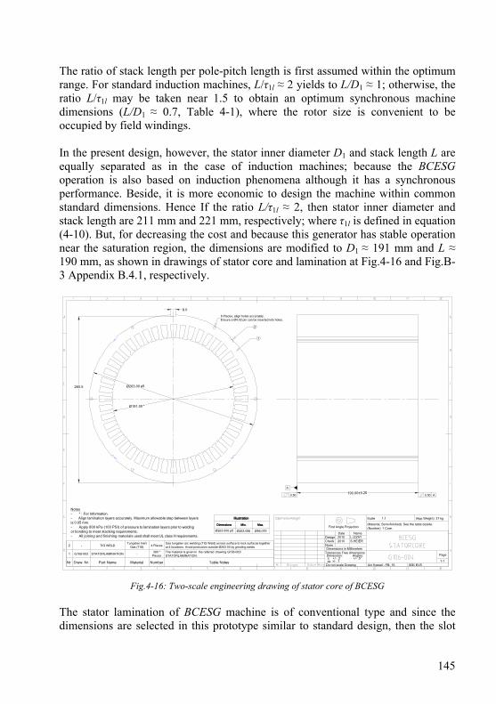
145
The ratio of stack length per pole-pitch length is first assumed within the optimum range. For standard induction machines, L/τ1l ≈ 2 yields to L/D1 ≈ 1; otherwise, the ratio L/τ1l may be taken near 1.5 to obtain an optimum synchronous machine dimensions (L/D1 ≈ 0.7, Table 4-1), where the rotor size is convenient to be occupied by field windings. In the present design, however, the stator inner diameter D1 and stack length L are equally separated as in the case of induction machines; because the BCESG operation is also based on induction phenomena although it has a synchronous performance. Beside, it is more economic to design the machine within common standard dimensions. Hence If the ratio L/τ1l ≈ 2, then stator inner diameter and stack length are 211 mm and 221 mm, respectively; where τ1l is defined in equation (4-10). But, for decreasing the cost and because this generator has stable operation near the saturation region, the dimensions are modified to D1 ≈ 191 mm and L ≈ 190 mm, as shown in drawings of stator core and lamination at Fig.4-16 and Fig.B-3 Appendix B.4.1, respectively.
Ø263.00 p5
Ø191.00 *
Uni Kassel - FB- 16Do not scale Drawing IEE/ EVS
Scale
Date
20102010Design
NormCheck
L.IZZATS.HEIER
Name
1:1 (App.Weight) 37 kg
1-1
Page
Dimensions in MillimetersTolerances Free dimensions Dimension: Angles: .x +/- .2 +/- .5° .xx +/- .1
6 Places, align holes accurately.Ensure a Ø4.02 pin can be inserted into holes.
1
2
260.5
8.0
190.00±0.25
A
0.50 0.50 A
Nr. Draw. Nr. Part Name Material Number Table Notes
1 G106-002 STATORLAMINATION -380 *
PiecesThe material is given in the referred drawing G106-002/STATORLAMINATION.
2 - TIG WELDTungsten Inert
Gas (TIG) 4 PlacesGas tungsten arc welding (TIG Weld) across surface to lock surfaces togetherat 4 locations. Avoid protrusion outside Ø263.00 by grinding welds.
Notes- * : For Information.- Align lamination layers accurately. Maximum allowable step between layersis 0.05 mm.- Apply 800 kPa (100 PSI) of pressure to lamination layers prior to weldingor bonding to meet stacking requirements.- All joining and finishing materials used shall meet UL class H requirements.
(Material, Semi-finished) See the table beside. (Number) 1 Core.
Illustration
Dimensions Min. Max.
Ø263.000 p5 Ø263.056 Ø56.079First Angle Projection
Fig.4-16: Two-scale engineering drawing of stator core of BCESG The stator lamination of BCESG machine is of conventional type and since the dimensions are selected in this prototype similar to standard design, then the slot
146
shape is chosen here as normal trapezoidal type (Fig.B-2c, Appendix B.3). Because of capacitor-exciter winding, two stator windings are available (m = 2), which are designed balanced, while the load winding is single-phase (ml =1). In addition, for better decrease in harmonics of MMF wave, the windings are distributed with double layer in four slots per pole per phase (q1 = 4), referring to article 4.5.4.1. Thus the total number of stator slots is obtained, S1 = 48. The tooth width (Wt1) is computed from equation (4-19) after assuming the ratio of pole arc to pole pitch length in the preferable range (τrat = 0.9), as explained in article 4.5.4.2; and calculating the maximum air-gap flux per pole (φ), from equations (4-32), (4-33). Hence: φ ≈ 0.00675 Wb and Wt1 ≥ 4.5 mm. But for parallel teeth and effective magnetic path Wt1 is increased to 5.5 mm, where the pole pitch length of stator windings, τ1l ≈ 100 mm is determined from equation (4-10). The permissible width of stator slot near air-gap surface can be obtained from equation (4-20), as Ws1 ≈ 7 mm (The shorter width of trapezoidal slot shape). Here, the slot length (depth) is taken three times of Ws1 ; thus hs = 21 mm. While the stator yoke height is given by equation (4-18), assuming suitable flux density for stator core (Bh1 =1.6 Wb/m2), stacking factor Kfe = 0.95 and voltage reduction factor KE = 0.97, as explained in article 4.5.3; hence, h1 ≈ 15 mm and Do ≈ 263 mm, referring to equation (4-17). 4.11.2 Air-gap and dimensions of rotor The SNSP rotor design may satisfy both the electromagnetic conditions and engineering measures. Therefore, by considering the size of the presented prototype and number of poles, the minimum air-gap length (lg1) may be obtained within a recommended range of air-gap ratio, referring to article 4.5.2. Hence, If lg1/τ1l = 0.01, then lg1 ≈ 1 mm. After determining lg1, as shown above; and by referring to lamination construction in Fig.4-11, the rotor outer diameter (D2) can easily be estimated as: D2 = D1 – 2 lg1 . Thus, D2 = 189 mm, which is considered as the finished dimension of rotor outer diameter. i.e. The final diameter that is obtained after technology process (machinery grinding) to achieve the centricity alignment of both the rotor output periphery and shaft center, as can be seen by the additional engineering-symbols on final dimensions of rotor subassembly drawing (core-shaft), Fig.B-4, Appendix B.4.2. However, as a stamped lamination cutting (stand-alone parts), the outer diameter of rotor lamination is taken equal to 190 mm (before technological process), as can be shown in the engineering drawing of Fig.4-17. Referring to article 4.5.3 and Table B-3, Appendix B.1, the inner diameter of rotor core (shaft diameter) can be assigned for this prototype machine (size 160L42) as

147
dsh = 60 mm, higher than drive-end diameter and bearings inner diameter. For investigation, equation (4-16) is applied later, after calculating the weight of rotor, G2 ; and determining the distance between bearings, Lb. Assuming a circular shape for rotor slots construction of type-S2n, as mentioned in article 4.5.4.2, the diameter of the circle (do2n) can then be determined from equations (4-21) and (B-1) Appendix B.6.1, at zero power factor to give the following relations,
πns
noAd 2
2 2×= ; where, wranns
wllns KJqpK
KTIaA22
22
11122
8.1= (4-103)
0.1 A
Equally SpacedOn a Ø66.00
0.1 A
A
Ø3.20+0.05 0.003X
Ø66.00
4.4+0.2 0
Ø152.0
Ø18.06XEqually SpacedOn a Ø169.00
6X 4.0
6X 28.0
6X 10.0
60.0° *
60.0° *39.91 *
30.0°
30.0°
5.0 *
2.0 *
0.1 A
6X 60.0°
6X 60.0°
120.0°3X
30.0°
3X 120.0°
Uni Kassel - FB- 16Do Not Scale Drawing IEE/ EVS
Scale(Material) Non oriented Electrical Steel Sheet M400-50A
(Number) 480 PiecesDate
Design
NormCheck.
Name
(App. Weight) 0.070 kg
1-1
Page
Thick 0.5mm, Max. core losses 4.00 W/kg at 1.5T, 50Hz.
Dimensions in MillimetersTolerance Free Dimensions Dimension: Angles: .x +/- .1 +/- .5° .xx +/- .05
6X 2XR7.0
6X 2XR4.0
" B "
4.0 *
2X R0.5
Detail " B " Scale 3:1
Notes- * : For Information.- Remove all burns greater than 0.03 mm.
6X 2XR10.0
2X R0.5
84.6 *
1.7 *
First Angle Projection
Ø169.00
Ø116.00
18.000±0.021
2X R0.4
Ø60.000+0.019 0.000
Ø190.00 0.00-0.20
6X 2X R2.0
1:1
S.HEIERL.IZZAT2010
2010
Fig.4-17: Two-scale engineering drawing of rotor lamination of BCESG By designing the rotor winding Wra for one parallel current path, then a2 =1; also for one slot of type-S2n per pole per phase, q2n=1. Then from article 4.5.5.4, the distribution factor is one and the chording factor is one; whence the winding factor of auxiliary rotor winding Kwra=1. Since the BCESG can generate even at no-load condition, where just the capacitors are connected in parallel at stator windings terminals; then machine is operating at zero power factor and sin ψ1 = 1, as explained in article 4.5.5.3. Now referring to article 4.5.4.2, the slot type-S2n
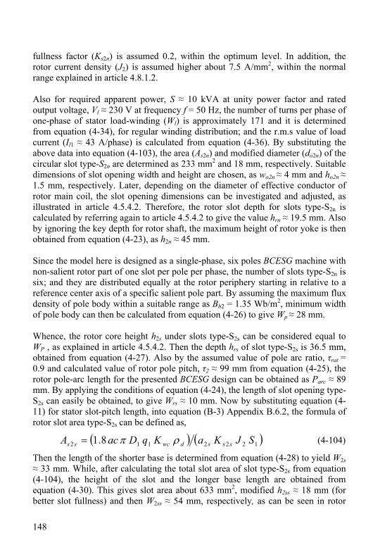
148
fullness factor (Ks2n) is assumed 0.2, within the optimum level. In addition, the rotor current density (J2) is assumed higher about 7.5 A/mm2, within the normal range explained in article 4.8.1.2. Also for required apparent power, S ≈ 10 kVA at unity power factor and rated output voltage, Vl ≈ 230 V at frequency f = 50 Hz, the number of turns per phase of one-phase of stator load-winding (Wl) is approximately 171 and it is determined from equation (4-34), for regular winding distribution; and the r.m.s value of load current (Il1 ≈ 43 A/phase) is calculated from equation (4-36). By substituting the above data into equation (4-103), the area (As2n) and modified diameter (do2n) of the circular slot type-S2n are determined as 233 mm2 and 18 mm, respectively. Suitable dimensions of slot opening width and height are chosen, as wo2n ≈ 4 mm and ho2n ≈ 1.5 mm, respectively. Later, depending on the diameter of effective conductor of rotor main coil, the slot opening dimensions can be investigated and adjusted, as illustrated in article 4.5.4.2. Therefore, the rotor slot depth for slots type-S2n is calculated by referring again to article 4.5.4.2 to give the value hrn ≈ 19.5 mm. Also by ignoring the key depth for rotor shaft, the maximum height of rotor yoke is then obtained from equation (4-23), as h2n ≈ 45 mm. Since the model here is designed as a single-phase, six poles BCESG machine with non-salient rotor part of one slot per pole per phase, the number of slots type-S2n is six; and they are distributed equally at the rotor periphery starting in relative to a reference center axis of a specific salient pole part. By assuming the maximum flux density of pole body within a suitable range as Bh2 = 1.35 Wb/m2, minimum width of pole body can then be calculated from equation (4-26) to give Wp ≈ 28 mm. Whence, the rotor core height h2s under slots type-S2s can be considered equal to WP , as explained in article 4.5.4.2. Then the depth hrs of slot type-S2s is 36.5 mm, obtained from equation (4-27). Also by the assumed value of pole arc ratio, τrat = 0.9 and calculated value of rotor pole pitch, τ2 ≈ 99 mm from equation (4-25), the rotor pole-arc length for the presented BCESG design can be obtained as Parc ≈ 89 mm. By applying the conditions of equation (4-24), the length of slot opening type-S2s can easily be obtained, to give Wrs ≈ 10 mm. Now by substituting equation (4-11) for stator slot-pitch length, into equation (B-3) Appendix B.6.2, the formula of rotor slot area type-S2s can be defined as,
( ) ( )1222112 8.1 SJKaKqDacA sssdwcss ρπ= (4-104)
Then the length of the shorter base is determined from equation (4-28) to yield W2s ≈ 33 mm. While, after calculating the total slot area of slot type-S2s from equation (4-104), the height of the slot and the longer base length are obtained from equation (4-30). This gives slot area about 633 mm2, modified h2ss ≈ 18 mm (for better slot fullness) and then W2ss ≈ 54 mm, respectively, as can be seen in rotor
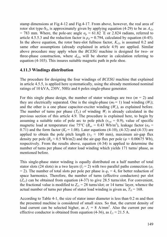
149
stamp dimensions at Fig.4-12 and Fig.4-17. From above, however, the real area of rotor slot type-S2s is approximately given by applying equation (4-29) to be as As2s = 783 mm. Where, the pole-arc angle αp ≈ 61.82 °E or 2.824 radians, referred to article 4.5.5.3 and the reduction factor is ρd = 0.794, calculated by equation (4-45). In the above equation, the rotor bare-slot fullness factor, Ks2s is assumed 0.2 and same other assumptions (already explained in article 4.9) are applied. Similar above procedure may apply when the BCESG machine is designed for two- or three-phase construction, where do2n will be shorter in calculation referring to equation (4-103). This insures suitable magnetic path in pole shoe. 4.11.3 Windings distribution The procedure for designing the four windings of BCESG machine that explained in article 4.5.5, is applied here systematically, using the already mentioned nominal ratings of 10 kVA, 230V, 50Hz and 6 poles single-phase generator. For this single phase design, the number of stator windings are two (m = 2) and they are electrically separated. One is the single-phase (ml = 1) load winding (Wl); and the other is a one phase capacitor-exciter winding (Wc), as explained before. The number of turns per phase (Tl1) of winding Wl is already calculated in the previous section of this article 4.9. The procedure is explained here, to begin by assuming a suitable ratio of pole arc to pole pitch (τrat = 0.9), value of specific magnetic load at temperature rise 75°C (Bav = 0.43 Wb/m2), leakage factor (αδ = 0.71) and the form factor (Kf = 1.08). Later equations (4-10), (4-32) and (4-33) are applied to obtain the pole pitch length (τ1l ≈ 100 mm), maximum air-gap flux density per pole (Bg ≈ 0.5 Wb/m2) and the air-gap flux per pole (φ ≈ 0.00675 Wb), respectively. From the results above, equation (4-34) is applied to determine the number of turns per phase of stator load winding which yields 171 turns/ phase, as mentioned before. This single-phase stator winding is equally distributed on a half number of total stator slots (24 slots) in a two layers (l1 = 2) with two parallel paths connection (a1 = 2). The number of total slots per pole per phase is q1 = 4, for better reduction of space harmonics. Therefore, the number of turns (effective conductors) per slot (Zs1) can be obtained from equation (4-37) to give 28.5 turns/slot. For convenient, the fractional value is modified to Zs1 = 28 turns/slot; or 14 turns/ layer, whence the actual number of turns per phase of stator load winding is given as, Tl1 = 168. According to Table 4-1, the size of stator inner diameter is less than 0.2 m and then the presented machine is considered of small sizes. So that, the current density of load current can be selected higher, as J1 = 8 A/mm2. Also the current per one effective conductor is obtained from equation (4-36), as Iz1 ≈ 21.5 A.
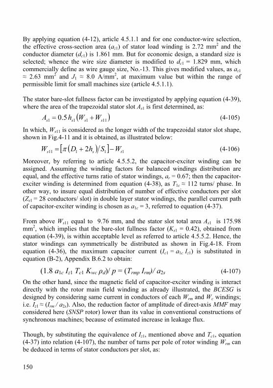
150
By applying equation (4-12), article 4.5.1.1 and for one conductor-wire selection, the effective cross-section area (az1) of stator load winding is 2.72 mm2 and the conductor diameter (dc1) is 1.861 mm. But for economic design, a standard size is selected; whence the wire size diameter is modified to dc1 = 1.829 mm, which commercially define as wire gauge size, No.-13. This gives modified values, as az1 ≈ 2.63 mm2 and J1 ≈ 8.0 A/mm2, at maximum value but within the range of permissible limit for small machines size (article 4.5.1.1). The stator bare-slot fullness factor can be investigated by applying equation (4-39), where the area of the trapezoidal stator slot As1 is first determined, as:
( )11111 5.0 ssss WWhA += (4-105)
In which, Ws11 is considered as the longer width of the trapezoidal stator slot shape, shown in Fig.4-11 and it is obtained, as illustrated below:
( )[ ] 11111 2 tss WShDW −+= π (4-106)
Moreover, by referring to article 4.5.5.2, the capacitor-exciter winding can be assigned. Assuming the winding factors for balanced windings distribution are equal, and the effective turns ratio of stator windings, ar = 0.67; then the capacitor-exciter winding is determined from equation (4-38), as T1c ≈ 112 turns/ phase. In other way, to insure equal distribution of number of effective conductors per slot (Zs1 = 28 conductors/ slot) in double layer stator windings, the parallel current path of capacitor-exciter winding is chosen as a1c = 3, referred to equation (4-37). From above Ws11 equal to 9.76 mm, and the stator slot total area As1 is 175.98 mm2, which implies that the bare-slot fullness factor (Ks1 = 0.42), obtained from equation (4-39), is within acceptable level as referred to article 4.5.5.2. Hence, the stator windings can symmetrically be distributed as shown in Fig.4-18. From equation (4-36), the maximum capacitor current (Ic1 = a1c Iz1) is substituted in equation (B-2), Appendix B.6.2 to obtain:
(1.8 a1c Iz1 Tc1 Kwc ρd)/ p = (Trmp Irm)/ a2s (4-107)
On the other hand, since the magnetic field of capacitor-exciter winding is interact directly with the rotor main field winding as already illustrated, the BCESG is designed by considering same current in conductors of each Wrm and Wc windings; i.e. Iz1 ≈ (Irm / a2s). Also, the reduction factor of amplitude of direct-axis MMF may considered here (SNSP rotor) lower than its value in conventional constructions of synchronous machines; because of estimated increase in leakage flux. Though, by substituting the equivalence of Iz1, mentioned above and Tc1, equation (4-37) into relation (4-107), the number of turns per pole of rotor winding Wrm can be deduced in terms of stator conductors per slot, as:
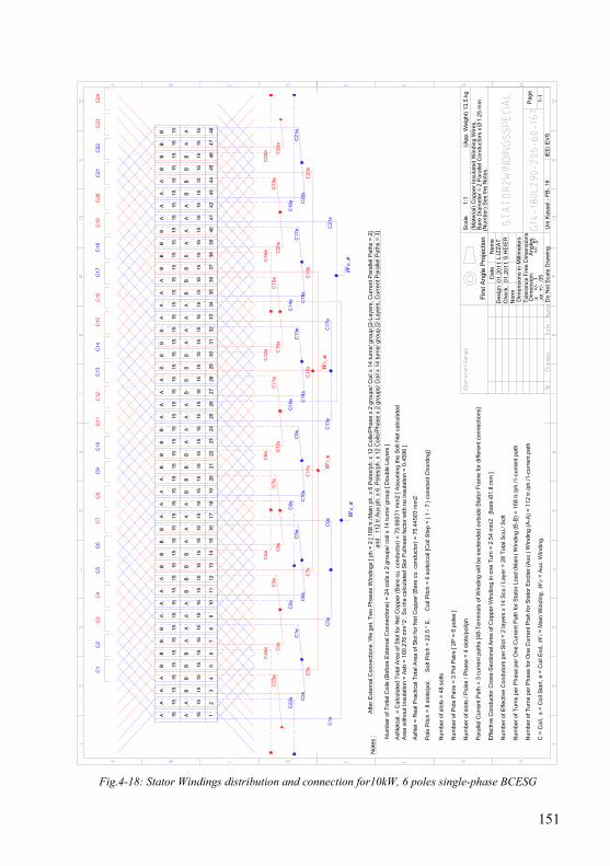
151
Uni
Kas
sel -
FB
- 16
Do
Not
Sca
le D
raw
ing
IEE
/ EV
S
Sca
le(M
ater
ial)
Cop
per
Insu
late
d W
indi
ng W
ires,
(Num
ber)
See
the
Not
es.
Dat
e
01.2
011
01.2
011
Des
ign
Nor
mC
heck
.L.
IZZ
AT
S.H
EIE
R
Nam
e
1:1
(App
. Wei
ght)
13.
5 kg
1-1
Pag
e
Bar
e D
iam
eter
= 2
Par
alle
l Con
duct
ors
x
1.25
mm
Dim
ensi
ons
in M
illim
eter
sT
oler
ance
Fre
e D
imen
sion
s D
imen
sion
:
Ang
les:
.x
+
/- .1
+
/- .5
° .
xx +
/- .0
5
Firs
t Ang
le P
roje
ctio
n
Fig.4-18: Stator Windings distribution and connection for10kW, 6 poles single-phase BCESG
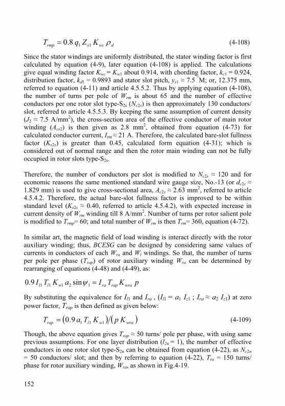
152
dwcsrmp KZqT ρ118.0= (4-108)
Since the stator windings are uniformly distributed, the stator winding factor is first calculated by equation (4-9), later equation (4-108) is applied. The calculations give equal winding factor Kwc = Kw1 about 0.914, with chording factor, kc1 = 0.924, distribution factor, kd1 = 0.9893 and stator slot pitch, ys1 ≈ 7.5 °M; or, 12.375 mm, referred to equation (4-11) and article 4.5.5.2. Thus by applying equation (4-108), the number of turns per pole of Wrm is about 65 and the number of effective conductors per one rotor slot type-S2s (Nc2s) is then approximately 130 conductors/ slot, referred to article 4.5.5.3. By keeping the same assumption of current density (J2 ≈ 7.5 A/mm2), the cross-section area of the effective conductor of main rotor winding (Acs2) is then given as 2.8 mm2, obtained from equation (4-73) for calculated conductor current, Irm ≈ 21 A. Therefore, the calculated bare-slot fullness factor (Ks2s) is greater than 0.45, calculated form equation (4-31); which is considered out of normal range and then the rotor main winding can not be fully occupied in rotor slots type-S2s. Therefore, the number of conductors per slot is modified to Nc2s ≈ 120 and for economic reasons the same mentioned standard wire gauge size, No.-13 (or dc2s ≈ 1.829 mm) is used to give cross-sectional area, Ac2s ≈ 2.63 mm2, referred to article 4.5.4.2. Therefore, the actual bare-slot fullness factor is improved to be within standard level (Ks2s ≈ 0.40, referred to article 4.5.4.2), with expected increase in current density of Wrm winding till 8 A/mm2. Number of turns per rotor salient pole is modified to Trmp= 60; and total number of Wrm is then Trm= 360, equation (4-72). In similar art, the magnetic field of load winding is interact directly with the rotor auxiliary winding; thus, BCESG can be designed by considering same values of currents in conductors of each Wra and Wl windings. So that, the number of turns per pole per phase (Trap) of rotor auxiliary winding Wra can be determined by rearranging of equations (4-48) and (4-49), as:
pKTIaKTI wraraprawll =12111 sin9.0 ψ
By substituting the equivalence for Il1 and Ira , (Il1 = a1 Iz1 ; Ira ≈ a2 Iz1) at zero power factor, Trap is then defined as given below:
( ) ( )wrawlrap KpKTaT 1119.0= (4-109)
Though, the above equation gives Trap ≈ 50 turns/ pole per phase, with using same previous assumptions. For one layer distribution (l2n = 1), the number of effective conductors in one rotor slot type-S2n can be obtained from equation (4-22), as Nc2n = 50 conductors/ slot; and then by referring to equation (4-22), Tra = 150 turns/ phase for rotor auxiliary winding, Wra, as shown in Fig.4-19.
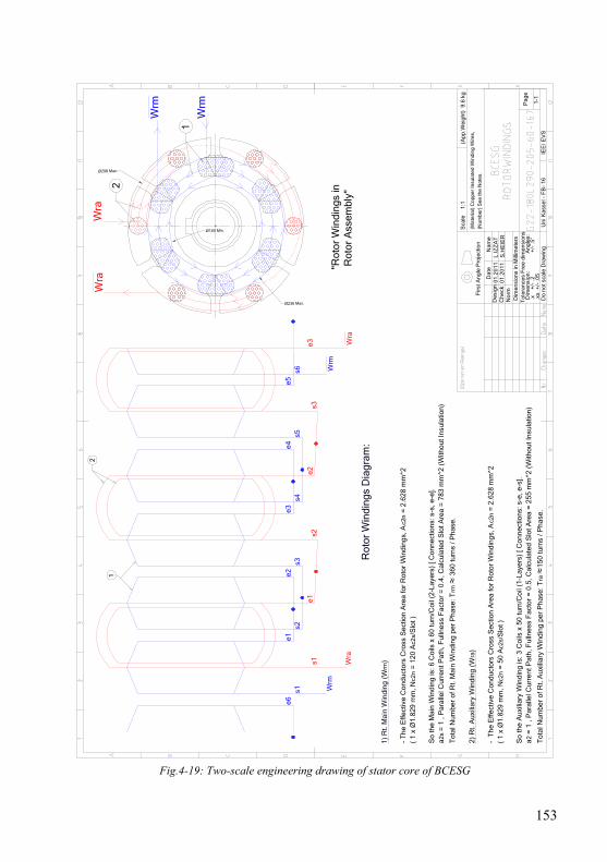
153
Dim
ensi
ons
in M
illim
eter
sT
oler
ance
s F
ree
dim
ensi
ons
Dim
ensi
on:
A
ngle
s: .
x
+/-
.2
+/-
.5°
.xx
+/-
.05
Firs
t Ang
le P
roje
ctio
n
Uni
Kas
sel -
FB
- 16
Do
not s
cale
Dra
win
gIE
E/ E
VS
Sca
le
Dat
e
01.2
011
01.2
011
Des
ign
Nor
mC
heck
L.IZ
ZA
TS
.HE
IER
Nam
e
1:1
(App
.Wei
ght)
9.6
kg
1-1
Pag
e
2
1
Rot
or W
indi
ngs
Dia
gram
:
1) R
t. M
ain
Win
ding
(W
rm)
- T
he E
ffect
ive
Con
duct
ors
Cro
ss S
ectio
n A
rea
for
Rot
or W
indi
ngs,
Ac2
n =
2.6
28 m
m^2
( 1
x Ø
1.82
9 m
m, N
c2n
= 1
20 A
c2s/
Slo
t )
So
the
Mai
n W
indi
ng is
: 6 C
oils
x 6
0 tu
rn/C
oil (
2-La
yers
) [ C
onne
ctio
ns: s
-s, e
-e].
a2s
= 1
, P
aral
lel C
urre
nt P
ath,
Ful
lnes
s F
acto
r =
0.4
, Cal
cula
ted
Slo
t Are
a =
783
mm
^2 (
With
out I
nsul
atio
n)
Tot
al N
umbe
r of
Rt.
Mai
n W
indi
ng p
er P
hase
: Trm
≈ 3
60 tu
rns
/ Pha
se.
2) R
t. A
uxili
ary
Win
ding
(W
ra)
- T
he E
ffect
ive
Con
duct
ors
Cro
ss S
ectio
n A
rea
for
Rot
or W
indi
ngs,
Ac2
n =
2.6
28 m
m^2
( 1
x Ø
1.82
9 m
m,
Nc2
n =
50
Ac2
s/S
lot )
So
the
Aux
iliar
y W
indi
ng is
: 3 C
oils
x 5
0 tu
rn/C
oil (
1-La
yers
) [ C
onne
ctio
ns: s
-e, e
-s].
a2 =
1 ,
Par
alle
l Cur
rent
Pat
h, F
ulln
ess
Fac
tor
= 0
.5, C
alcu
late
d S
lot A
rea
= 2
55 m
m^2
(W
ithou
t Ins
ulat
ion)
Tot
al N
umbe
r of
Rt.
Aux
iliar
y W
indi
ng p
er P
hase
: Tra
≈15
0 tu
rns
/ Pha
se.
Wra
Wrm
e1e2
e3e4
e5s2
s3s4
s5s6
e6s1
s1e1
s2e2
s3e3 W
ra
Wrm
Wrm
Wrm
Wra
Wra
Ø298 Max.
Ø236 Max.
Ø160 Min.
"Rot
or W
indi
ngs
in R
otor
Ass
embl
y"
1
2
(Mat
eria
l) C
oppe
r In
sula
ted
Win
ding
Wire
s,
(Num
ber)
See
the
Not
es.
Fig.4-19: Two-scale engineering drawing of stator core of BCESG
154
Also, by taking the economic aspects into consideration, the cross sectional area of effective conductor is selected here similar to that for rotor main winding. Then Ac2n ≈ 2.628 mm2 and dc2n = 1.829 mm (wire gauge No.-13), applying equation (4-73) and definition of equation (4-21); where the current density and conductor current in winding Wra are also assumed as J2 = 7.5 A/mm2 and Ira ≈ 21 A, respectively. Moreover, the actual slot area is applied, according to the modified dimension do2n = 18 mm, to give modified As2n = 255 mm2, referred to equation (4-21). For investigation, equation (4-21) is applied to yield slot fullness factor, as Ks2n ≈ 0.50, which is considered of higher value, but still within the optimal ranges, explained in article 4.5.4.2. As long as the assumptions and design calculations results are within normal preferable limits, then the designed dimensions and windings are successfully applicable in manufacture, as found in practical part, chapter six; and the theoretical calculations to determine the magnetic circuit, parameters and machine performance is then continued, as shown in the following articles. 4.12 Design results for BCESG and design sheet of generators at
markets After determining the dimensions and windings design for the presented developed BCESG machine, the results of theoretical design calculations are performed by relying on the analytical equations, already derived in this chapter and chapter three of this dissertation. A basic computer program with simple iterations may also be organized to facilitate and accelerate the results data. The design data are presented in the next article. On the other hand, expert software, specialist in designing and optimizing conventional types of rotating electrical machines (ANSOFT-RMxprt under ANSYS series), is applied. Then, the design data of same size 10 kVA × 6 poles from salient-pole and non-salient-pole of three phase synchronous generators is determined. Therefore, the comparison between the performance of developed BCESG and the mentioned synchronous machines (known in markets) are easily obtained. The analytic-calculation results (Output design data from software) are comprehensively illustrated, as shown in Appendix B.8. In the following articles however, the main descriptions and differences in results are focused; and discussion for each type is made. 4.12.1 Results of magnetic circuit, parameters and performance of
BCESG As explained above, a simple computer program is applied to obtain the design data sheet of 10 kW, 6 poles BCESG machine that diagrammatically shown in
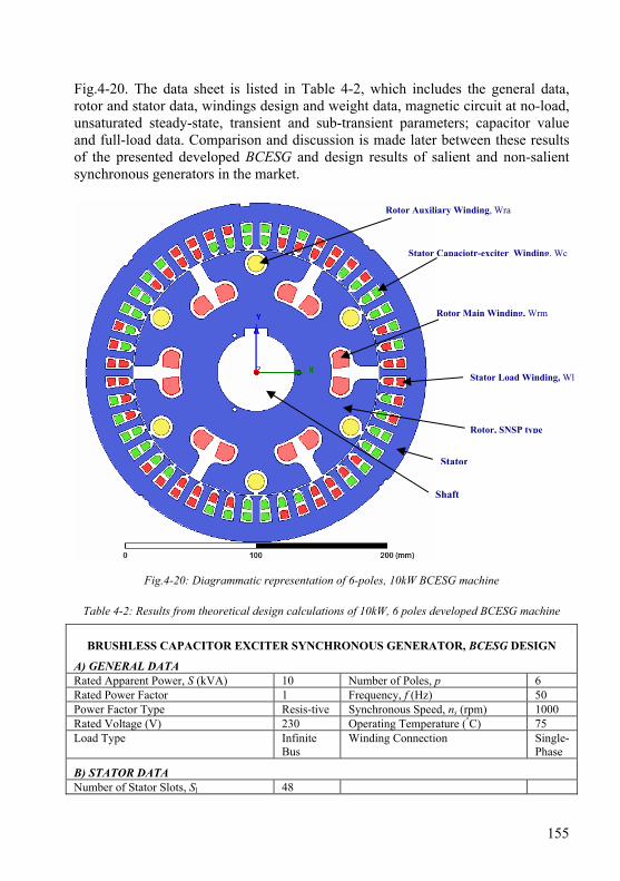
155
Fig.4-20. The data sheet is listed in Table 4-2, which includes the general data, rotor and stator data, windings design and weight data, magnetic circuit at no-load, unsaturated steady-state, transient and sub-transient parameters; capacitor value and full-load data. Comparison and discussion is made later between these results of the presented developed BCESG and design results of salient and non-salient synchronous generators in the market.
Fig.4-20: Diagrammatic representation of 6-poles, 10kW BCESG machine
Table 4-2: Results from theoretical design calculations of 10kW, 6 poles developed BCESG machine
BRUSHLESS CAPACITOR EXCITER SYNCHRONOUS GENERATOR, BCESG DESIGN
A) GENERAL DATA Rated Apparent Power, S (kVA) 10 Number of Poles, p 6 Rated Power Factor 1 Frequency, f (Hz) 50 Power Factor Type Resis-tive Synchronous Speed, ns (rpm) 1000 Rated Voltage (V) 230 Operating Temperature (°C) 75 Load Type Infinite
Bus Winding Connection Single-
Phase
B) STATOR DATA Number of Stator Slots, Sl 48
Stator Capaciotr-exciter Winding, Wc
Stator Load Winding, Wl
Rotor, SNSP type
Rotor Auxiliary Winding, Wra
Stator
Rotor Main Winding, Wrm
Shaft
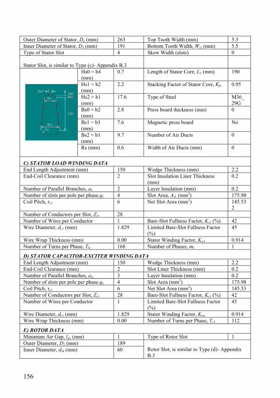
156
Outer Diameter of Stator, Do (mm) 263 Top Tooth Width (mm) 5.3 Inner Diameter of Stator, D1 (mm) 191 Bottom Tooth Width, Wt1 (mm) 5.5 Type of Stator Slot 4 Skew Width (slots) 0 Stator Slot, is similar to Type (c)- Appendix B.3
Hs0 = h4 (mm)
0.7 Length of Stator Core, L1 (mm) 190
Hs1 = h2 (mm)
2.2 Stacking Factor of Stator Core, Kfe 0.95
Hs2 = h1 (mm)
17.6 Type of Steel M36_ 29G
Bs0 = b2 (mm)
2.8 Press board thickness (mm) 0
Bs1 = b3 (mm)
7.6 Magnetic press board No
Bs2 = b1 (mm)
9.7 Number of Air Ducts 0
Rs (mm) 0.6 Width of Air Ducts (mm) 0
C) STATOR LOAD WINDING DATA End Length Adjustment (mm) 150 Wedge Thickness (mm) 2.2 End-Coil Clearance (mm) 2 Slot Insulation Liner Thickness
(mm) 0.2
Number of Parallel Branches, a1 2 Layer Insulation (mm) 0.2 Number of slots per pole per phase, q1 4 Slot Area, As1 (mm2) 175.98 Coil Pitch, τc1 6 Net Slot Area (mm2) 145.53
2 Number of Conductors per Slot, Zs1 28 Number of Wires per Conductor 1 Bare-Slot Fullness Factor, Ks1 (%) 42 Wire Diameter, dc1 (mm) 1.829 Limited Bare-Slot Fullness Factor
(%) 45
Wire Wrap Thickness (mm) 0.00 Stator Winding Factor, Kw1 0.914 Number of Turns per Phase, Tl1 168 Number of Phases, ml 1
D) STATOR CAPACITOR-EXCITER WINDING DATA End Length Adjustment (mm) 150 Wedge Thickness (mm) 2.2 End-Coil Clearance (mm) 2 Slot Liner Thickness (mm) 0.2 Number of Parallel Branches, a1c 3 Layer Insulation (mm) 0.2 Number of slots per pole per phase, q1 4 Slot Area (mm2) 175.98 Coil Pitch, τc1 6 Net Slot Area (mm2) 145.53 Number of Conductors per Slot, Zs1 28 Bare-Slot Fullness Factor, Ks1 (%) 42 Number of Wires per Conductor 1 Limited Bare-Slot Fullness Factor
(%) 45
Wire Diameter, dc1 (mm) 1.829 Stator Winding Factor, Kwc 0.914 Wire Wrap Thickness (mm) 0.00 Number of Turns per Phase, Tc1 112
E) ROTOR DATA Minimum Air Gap, lg1 (mm) 1 Type of Rotor Slot 1 Outer Diameter, D2 (mm) 189 Inner Diameter, dsh (mm) 60
Rotor Slot, is similar to Type (d)- Appendix B.3
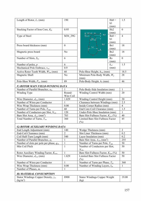
157
Length of Rotor, L1 (mm) 190 Hs0 = h1 (mm)
1.5
Stacking Factor of Iron Core, Kfe 0.95 Hs2 (mm)
0
Type of Steel M36_29G Bs0 = b1 (mm)
4
Press board thickness (mm) 0 Bs1 (mm)
18
Magnetic press board No Bs2 (mm)
18
Number of Slots, S2n 6 Rs (mm)
0
Number of poles, p 6 Mechanical Pole Embrace, τrat 0.9
krd (mm)
1.5
Active Rotor Tooth Width, Wt2n (mm) 60 Pole-Shoe Height, ht2n (mm) 18.5 Magnetic Shaft No Minimum Pole-Body Width, Wp
(mm) 28
Pole-Shoe Width, Parc (mm) 89 Pole-Body Height, h2 (mm) 46
F) ROTOR MAIN FIELD-WINDING DATA Number of Parallel Branches, a2s 1 Pole-Body-Side Insulation (mm) 1 Winding Type Round-
Wire Coil Winding Control Width (mm) 20
Wire Diameter, dc2s (mm) 1.829 Winding Control Height (mm) 20 Number of Wires per Conductor 1 Clearance between Windings (mm) 2.5 Wire Wrap Thickness (mm) 0.00 Inside Corner Radius (mm) 4 Number of Turns per Pole, Trmp 60 End Core-Coil Clearance (mm) 1.5 Number of Conductors per Slot, Nc2s 120 Under-Pole-Shoe Insulation (mm) 1 Bare Slot Area, As2s (mm2) 783 Bare Slot Fullness Factor, Ks2s (%) 40 Total Number of Turns, Trm 360 Limited Bare Slot Fullness Factor
(%) 45
G) ROTOR AUXILIARY WINDING DATA End Length Adjustment (mm) 140 Wedge Thickness (mm) 2 End-Coil Clearance (mm) 2 Slot Liner Thickness (mm) 0.2 Coil Half-Turn Length (mm) 540 Layer Insulation (mm) 0.2 Number of Parallel Branches, a2 1 Bare Slot Area, As2n (mm2) 255 Number of slots per pole per phase, q2n 1 Number of Turns per Pole, Trap 50 Min Coil Pitch 1 Number of Conductors per Slot,
Nc2n 50
Rotor Auxiliary Winding Factor, Kwra 1 Bare Slot Fullness Factor, Ks2n (%) 50 Wire Diameter, dc2n (mm) 1.829 Limited Bare Slot Fullness Factor
(%) 50
Number of Wires per Conductor 1 Number of Turns per Phase, Trp 360 Wire Wrap Thickness (mm) 0.00 Number of Winding Layers, l2n 1 Number of Phases, ml 1
H) MATERIAL CONSUMPTION Stator Windings Copper Density, γc1 (kg/m3)
8900 Stator Windings Copper Weight (kg)
19.00
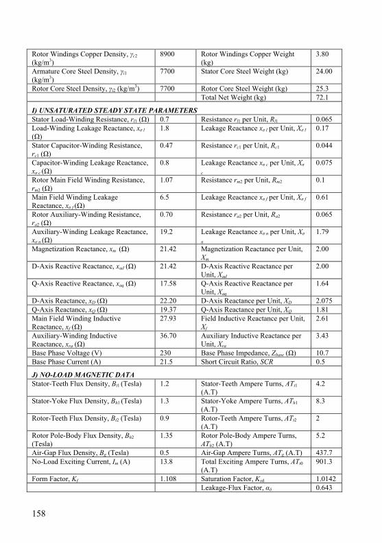
158
Rotor Windings Copper Density, γc2 (kg/m3)
8900 Rotor Windings Copper Weight (kg)
3.80
Armature Core Steel Density, γi1 (kg/m3)
7700 Stator Core Steel Weight (kg) 24.00
Rotor Core Steel Density, γi2 (kg/m3) 7700 Rotor Core Steel Weight (kg) 25.3 Total Net Weight (kg) 72.1
I) UNSATURATED STEADY STATE PARAMETERS Stator Load-Winding Resistance, rl1 (Ω) 0.7 Resistance rl1 per Unit, Rl1 0.065 Load-Winding Leakage Reactance, xσ l (Ω)
1.8 Leakage Reactance xσ l per Unit, Xσ l 0.17
Stator Capacitor-Winding Resistance, rc1 (Ω)
0.47 Resistance rc1 per Unit, Rc1 0.044
Capacitor-Winding Leakage Reactance, xσ c (Ω)
0.8 Leakage Reactance xσ c per Unit, Xσ
c 0.075
Rotor Main Field Winding Resistance, rm2 (Ω)
1.07 Resistance rm2 per Unit, Rm2 0.1
Main Field Winding Leakage Reactance, xσ f (Ω)
6.5 Leakage Reactance xσ f per Unit, Xσ f 0.61
Rotor Auxiliary-Winding Resistance, ra2 (Ω)
0.70 Resistance ra2 per Unit, Ra2 0.065
Auxiliary-Winding Leakage Reactance, xσ n (Ω)
19.2 Leakage Reactance xσ n per Unit, Xσ
n 1.79
Magnetization Reactance, xm (Ω) 21.42 Magnetization Reactance per Unit, Xm
2.00
D-Axis Reactive Reactance, xad (Ω) 21.42 D-Axis Reactive Reactance per Unit, Xad
2.00
Q-Axis Reactive Reactance, xaq (Ω) 17.58 Q-Axis Reactive Reactance per Unit, Xaq
1.64
D-Axis Reactance, xD (Ω) 22.20 D-Axis Reactance per Unit, XD 2.075 Q-Axis Reactance, xQ (Ω) 19.37 Q-Axis Reactance per Unit, XQ 1.81 Main Field Winding Inductive Reactance, xf (Ω)
27.93 Field Inductive Reactance per Unit, Xf
2.61
Auxiliary-Winding Inductive Reactance, xra (Ω)
36.70 Auxiliary Inductive Reactance per Unit, Xra
3.43
Base Phase Voltage (V) 230 Base Phase Impedance, Zbase (Ω) 10.7 Base Phase Current (A) 21.5 Short Circuit Ratio, SCR 0.5
J) NO-LOAD MAGNETIC DATA Stator-Teeth Flux Density, Bt1 (Tesla) 1.2 Stator-Teeth Ampere Turns, ATt1
(A.T) 4.2
Stator-Yoke Flux Density, Bh1 (Tesla) 1.3 Stator-Yoke Ampere Turns, ATh1
(A.T) 8.3
Rotor-Teeth Flux Density, Bt2 (Tesla) 0.9 Rotor-Teeth Ampere Turns, ATt2
(A.T) 2
Rotor Pole-Body Flux Density, Bh2 (Tesla)
1.35 Rotor Pole-Body Ampere Turns, ATh2 (A.T)
5.2
Air-Gap Flux Density, Bg (Tesla) 0.5 Air-Gap Ampere Turns, ATg (A.T) 437.7 No-Load Exciting Current, Im (A) 13.8 Total Exciting Ampere Turns, ATt0
(A.T) 901.3
Form Factor, Kf 1.108 Saturation Factor, Ksd 1.0142 Leakage-Flux Factor, αδ 0.643
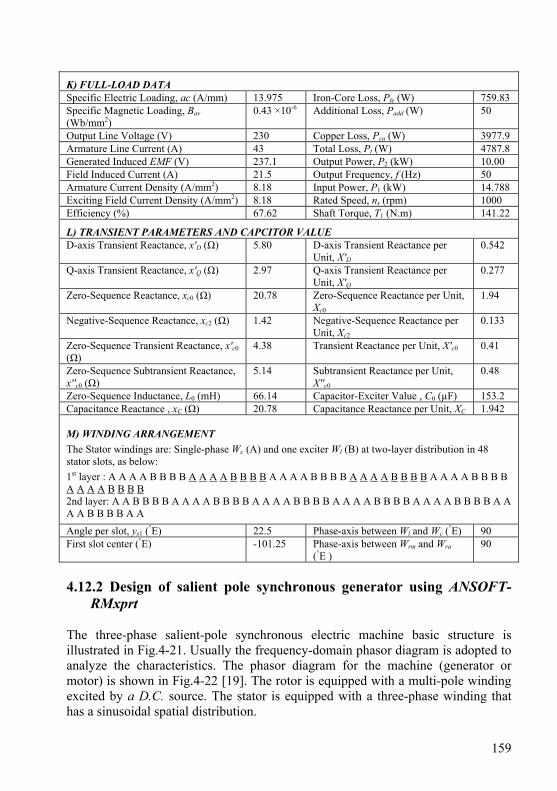
159
K) FULL-LOAD DATA Specific Electric Loading, ac (A/mm) 13.975 Iron-Core Loss, Pfe (W) 759.83 Specific Magnetic Loading, Bav (Wb/mm2)
0.43 ×10⁻⁶ Additional Loss, Padd (W) 50
Output Line Voltage (V) 230 Copper Loss, Pcu (W) 3977.9 Armature Line Current (A) 43 Total Loss, Pt (W) 4787.8 Generated Induced EMF (V) 237.1 Output Power, P2 (kW) 10.00 Field Induced Current (A) 21.5 Output Frequency, f (Hz) 50 Armature Current Density (A/mm2) 8.18 Input Power, P1 (kW) 14.788 Exciting Field Current Density (A/mm2) 8.18 Rated Speed, ns (rpm) 1000 Efficiency (%) 67.62 Shaft Torque, T1 (N.m) 141.22
L) TRANSIENT PARAMETERS AND CAPCITOR VALUE D-axis Transient Reactance, x'D (Ω) 5.80 D-axis Transient Reactance per
Unit, X'D 0.542
Q-axis Transient Reactance, x'Q (Ω) 2.97 Q-axis Transient Reactance per Unit, X'Q
0.277
Zero-Sequence Reactance, xc0 (Ω) 20.78 Zero-Sequence Reactance per Unit, Xc0
1.94
Negative-Sequence Reactance, xc2 (Ω) 1.42 Negative-Sequence Reactance per Unit, Xc2
0.133
Zero-Sequence Transient Reactance, x'c0 (Ω)
4.38 Transient Reactance per Unit, X'c0 0.41
Zero-Sequence Subtransient Reactance, x''c0 (Ω)
5.14 Subtransient Reactance per Unit, X''c0
0.48
Zero-Sequence Inductance, L0 (mH) 66.14 Capacitor-Exciter Value , C0 (µF) 153.2 Capacitance Reactance , xC (Ω) 20.78 Capacitance Reactance per Unit, XC 1.942 M) WINDING ARRANGEMENT
The Stator windings are: Single-phase Wc (A) and one exciter Wl (B) at two-layer distribution in 48 stator slots, as below:
1st layer : A A A A B B B B A A A A B B B B A A A A B B B B A A A A B B B B A A A A B B B B A A A A B B B B 2nd layer: A A B B B B A A A A B B B B A A A A B B B B A A A A B B B B A A A A B B B B A A A A B B B B A A
Angle per slot, ys1 (°E) 22.5 Phase-axis between Wl and Wc (°E) 90 First slot center (°E) -101.25 Phase-axis between Wrm and Wra
(°E ) 90
4.12.2 Design of salient pole synchronous generator using ANSOFT-
RMxprt The three-phase salient-pole synchronous electric machine basic structure is illustrated in Fig.4-21. Usually the frequency-domain phasor diagram is adopted to analyze the characteristics. The phasor diagram for the machine (generator or motor) is shown in Fig.4-22 [19]. The rotor is equipped with a multi-pole winding excited by a D.C. source. The stator is equipped with a three-phase winding that has a sinusoidal spatial distribution.
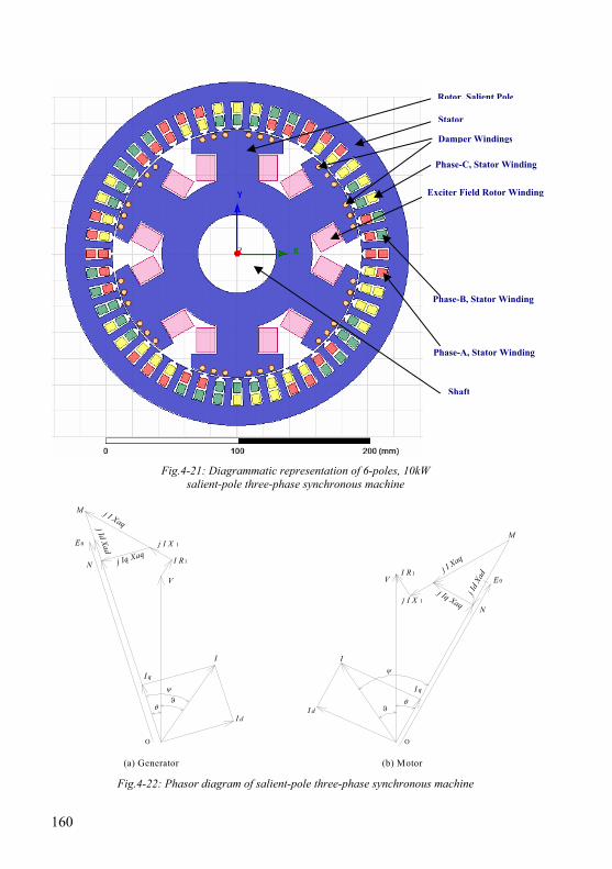
160
Fig.4-21: Diagrammatic representation of 6-poles, 10kW salient-pole three-phase synchronous machine
I q
O
I
I d
V
j I X 1
j I Xaq
N j Iq XaqI R1
M
E0
j Id Xad
θϑ
ψ
O
I d
I q
I
VI R1
j I X 1j Iq Xaq
N
E 0
j I Xaq
M
j Id
Xad
θϑ
ψ
(b) Motor(a) Generator
Fig.4-22: Phasor diagram of salient-pole three-phase synchronous machine
Phase-B, Stator Winding
Phase-C, Stator Winding
Phase-A, Stator Winding
Rotor, Salient Pole
Damper Windings
Stator
Exciter Field Rotor Winding
Shaft
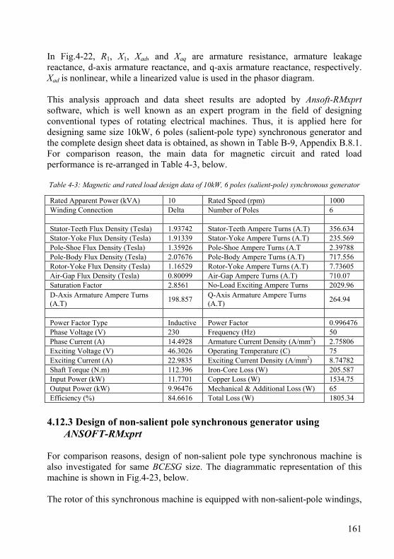
161
In Fig.4-22, R1, X1, Xad, and Xaq are armature resistance, armature leakage reactance, d-axis armature reactance, and q-axis armature reactance, respectively. Xad is nonlinear, while a linearized value is used in the phasor diagram. This analysis approach and data sheet results are adopted by Ansoft-RMxprt software, which is well known as an expert program in the field of designing conventional types of rotating electrical machines. Thus, it is applied here for designing same size 10kW, 6 poles (salient-pole type) synchronous generator and the complete design sheet data is obtained, as shown in Table B-9, Appendix B.8.1. For comparison reason, the main data for magnetic circuit and rated load performance is re-arranged in Table 4-3, below. Table 4-3: Magnetic and rated load design data of 10kW, 6 poles (salient-pole) synchronous generator
Rated Apparent Power (kVA) 10 Rated Speed (rpm) 1000 Winding Connection Delta Number of Poles 6 Stator-Teeth Flux Density (Tesla) 1.93742 Stator-Teeth Ampere Turns (A.T) 356.634 Stator-Yoke Flux Density (Tesla) 1.91339 Stator-Yoke Ampere Turns (A.T) 235.569 Pole-Shoe Flux Density (Tesla) 1.35926 Pole-Shoe Ampere Turns (A.T 2.39788 Pole-Body Flux Density (Tesla) 2.07676 Pole-Body Ampere Turns (A.T) 717.556 Rotor-Yoke Flux Density (Tesla) 1.16529 Rotor-Yoke Ampere Turns (A.T) 7.73605 Air-Gap Flux Density (Tesla) 0.80099 Air-Gap Ampere Turns (A.T) 710.07 Saturation Factor 2.8561 No-Load Exciting Ampere Turns 2029.96 D-Axis Armature Ampere Turns (A.T) 198.857 Q-Axis Armature Ampere Turns
(A.T) 264.94
Power Factor Type Inductive Power Factor 0.996476 Phase Voltage (V) 230 Frequency (Hz) 50 Phase Current (A) 14.4928 Armature Current Density (A/mm2) 2.75806 Exciting Voltage (V) 46.3026 Operating Temperature (C) 75 Exciting Current (A) 22.9835 Exciting Current Density (A/mm2) 8.74782 Shaft Torque (N.m) 112.396 Iron-Core Loss (W) 205.587 Input Power (kW) 11.7701 Copper Loss (W) 1534.75 Output Power (kW) 9.96476 Mechanical & Additional Loss (W) 65 Efficiency (%) 84.6616 Total Loss (W) 1805.34
4.12.3 Design of non-salient pole synchronous generator using
ANSOFT-RMxprt For comparison reasons, design of non-salient pole type synchronous machine is also investigated for same BCESG size. The diagrammatic representation of this machine is shown in Fig.4-23, below. The rotor of this synchronous machine is equipped with non-salient-pole windings,
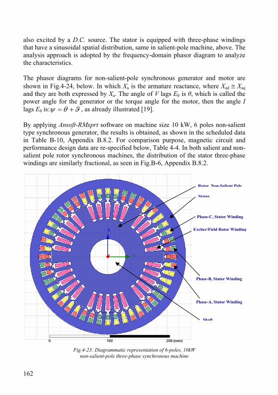
162
also excited by a D.C. source. The stator is equipped with three-phase windings that have a sinusoidal spatial distribution, same in salient-pole machine, above. The analysis approach is adopted by the frequency-domain phasor diagram to analyze the characteristics. The phasor diagrams for non-salient-pole synchronous generator and motor are shown in Fig.4-24, below. In which Xa is the armature reactance, where Xad ≅ Xaq and they are both expressed by Xa. The angle of V lags E0 is θ, which is called the power angle for the generator or the torque angle for the motor, then the angle I lags E0 is: ϑθψ += , as already illustrated [19]. By applying Ansoft-RMxprt software on machine size 10 kW, 6 poles non-salient type synchronous generator, the results is obtained, as shown in the scheduled data in Table B-10, Appendix B.8.2. For comparison purpose, magnetic circuit and performance design data are re-specified below, Table 4-4. In both salient and non-salient pole rotor synchronous machines, the distribution of the stator three-phase windings are similarly fractional, as seen in Fig.B-6, Appendix B.8.2.
Fig.4-23: Diagrammatic representation of 6-poles, 10kW non-salient-pole three-phase synchronous machine
Phase-B, Stator Winding
Phase-C, Stator Winding
Phase-A, Stator Winding
Rotor, Non-Salient Pole
Stator
Exciter/Field Rotor Winding
Shaft
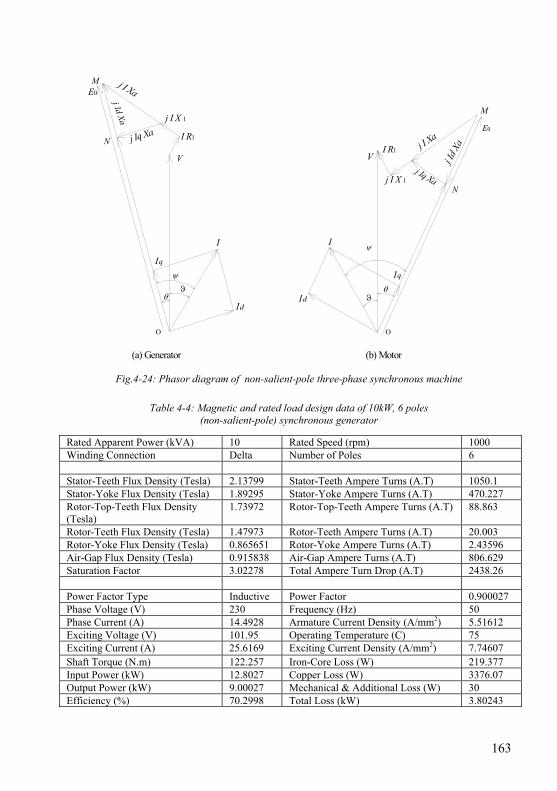
163
Iq
O
I
Id
V
j I X 1
j I Xa
N j Iq Xa I R1
ME0
j Id Xa
θϑ
ψ
O
Id
Iq
I
VI R1
j I X 1j Iq Xa
N
E0
j I Xa
M
j Id X
a
θϑ
ψ
(b) Motor(a) Generator
Fig.4-24: Phasor diagram of non-salient-pole three-phase synchronous machine
Table 4-4: Magnetic and rated load design data of 10kW, 6 poles (non-salient-pole) synchronous generator
Rated Apparent Power (kVA) 10 Rated Speed (rpm) 1000 Winding Connection Delta Number of Poles 6 Stator-Teeth Flux Density (Tesla) 2.13799 Stator-Teeth Ampere Turns (A.T) 1050.1 Stator-Yoke Flux Density (Tesla) 1.89295 Stator-Yoke Ampere Turns (A.T) 470.227 Rotor-Top-Teeth Flux Density (Tesla)
1.73972 Rotor-Top-Teeth Ampere Turns (A.T) 88.863
Rotor-Teeth Flux Density (Tesla) 1.47973 Rotor-Teeth Ampere Turns (A.T) 20.003 Rotor-Yoke Flux Density (Tesla) 0.865651 Rotor-Yoke Ampere Turns (A.T) 2.43596 Air-Gap Flux Density (Tesla) 0.915838 Air-Gap Ampere Turns (A.T) 806.629 Saturation Factor 3.02278 Total Ampere Turn Drop (A.T) 2438.26 Power Factor Type Inductive Power Factor 0.900027 Phase Voltage (V) 230 Frequency (Hz) 50 Phase Current (A) 14.4928 Armature Current Density (A/mm2) 5.51612 Exciting Voltage (V) 101.95 Operating Temperature (C) 75 Exciting Current (A) 25.6169 Exciting Current Density (A/mm2) 7.74607 Shaft Torque (N.m) 122.257 Iron-Core Loss (W) 219.377 Input Power (kW) 12.8027 Copper Loss (W) 3376.07 Output Power (kW) 9.00027 Mechanical & Additional Loss (W) 30 Efficiency (%) 70.2998 Total Loss (kW) 3.80243

164
4.13 Conclusions from results comparison and discussion In comparing the theoretical results at Tables 4-2, 4-3 and 4-4 (mentioned above), it is found that: 1- The synchronous machines have same volume size and give same output power (10 kW) at 1000 rpm synchronous speed, although the BCESG machine is designed as single-phase and the other both salient and non-salient machines are three phase. In addition, the presented BCESG machine can also be designed as two phase or three phase synchronous generator from same machine size, by redesigning the windings and slots for rotor and stator stamp. 2- The stator core structure, slot type and material is common for the three types of synchronous machines, as shown in Fig.4-25. More, the stator windings are fractionally distributed in salient and non-salient synchronous machine, as three-phase balanced armature windings; whereas two windings (armature and capacitor-exciter windings) can symmetrically be distributed in the stator slots of developed BCESG machine (shown in Fig.4-20) with higher value of winding factor and better slot fullness factor. 3- The rotor of BCESG contained salient poles in addition to non-salient slots type. They separately designed on the same steel core and are occupied with field winding and auxiliary rotor winding, as already explained. This is symmetrical to the exciter field rotor winding and damper winding in conventional synchronous generators, as can be seen in Fig.4-21. 4- For economic aspects, total net weight of steel core and windings of rotor and stator of presented BCESG machine is approximately equal to that in synchronous salient-pole three phase machines. However, it is much less from the total weight of core and windings of non-salient-pole three phase synchronous machines. 5- Taking the rated voltage and phase winding current as a base value, the per unit direct-axis synchronous direct axis reactance of BCESG machine is approximately double its value in salient or no-salient pole synchronous machines. Hence, the SCR in BCESG machine is lower than its value in the other both machines types. However, at low value of SCR the inherent voltage regulation of the machine is poor, and thus has greater changes in voltage under fluctuations of load. Also the machine has a lower stability limit as the maximum power output of the machine is inversely proportional to XD . More, the machines with low SCR are difficult to operate in parallel because a high value of XD gives a small synchronizing power. This power is responsible for keeping the machines in synchronism.
165
When the machines are interconnected through a transmission line, the parallel operation with high value of XD becomes more difficult. This is because the impedance of the line between generators adds directly to the sum of the impedance of the machines. This increase in impedance acts to reduce the synchronizing power so that they are weakly held in synchronism. They become more sensitive to torque and voltage disturbances. Also the decreased synchronizing power is more likely to lead to disconnections of individual units of apparatus and shut downs from the operation of automatically re-closing type circuit breakers. Moreover, a small value of SCR indicates a smaller value of current under short circuit conditions owing to large value of synchronous reactance. But this is not a problem, because the short circuit currents can be limited and thus the synchronous generators need not to be designed with large values of synchronous reactance (i.e. low values of SCR). Above all, Machine feeding long transmission lines should not be designed with a small short circuit ratio (high XD) as this would lead to large voltages on open circuit produced by self excitation owing to large capacitive currents drawn by the transmission lines. On the other hand a higher value of SCR means a high value of short circuit current. Also a machine designed with a higher value of SCR has a long air gap which means that the MMF required by the field is large. Hence a machine having a higher value of SCR is costlier to build. Present trend is to design the machine with a low value of SCR. This is due to the recent advancement in the fast acting control and excitation systems [4]. 6- From magnetic circuit comparison, it is obvious that the BCESG machine magnetic saturation (at saturation factor Ksd and maximum flux density, Bh2) is lower than the other synchronous machines, under discussion. However, the flux density in some parts of the presented BCESG machine is lower than the favorable limits; hence the machine dimensions at some parts can considerably be reduced to obtain the regular magnetic distribution for same output power; whence this product becomes more economic in manufacturing in comparing to the other mentioned synchronous machines types. 7- By assuming a fundamental harmonics waveform at a resonant frequency equal to output frequency (f), the value of capacitor C0 required for self-excitation of BCESG machine can be determined by applying general equation of resonant circuit, parallel inductive-capacitive circuit (article 3.5.4 Chapter three). 8- In the data of performance at full-load and unity power factor, the efficiency and shaft-torque in BCESG and non-salient synchronous generators are approximately
166
similar. However, these machines have lower efficiency than the case in salient-pole three-phase synchronous generator; because of higher copper losses due to higher current density. To decrease the current density, wider diameter of copper wires may be used and thus leads to modify the efficiency of BCESG machine, as long as the steel core part can be reduced to modify the magnetic circuit densities. The comparison of other design parameters for the above three types of synchronous machine may better be illustrated by using FEM magnetic simulation (QUICKFIELD and ANSOFT-MAXWELL software), which is followed next in chapter five.

167
Chapter 5
Electromagnetic Simulation of BCESG and Response Study Compared to Simulation Results of Machines at Markets
In this chapter finite element method is applied and the presented developed BCESG machine has been analyzed and simulated. Static simulation at no-load and full-load steady-state operation is demonstrated. Several cases of dynamic analysis on electromagnetic model with connected rectified diodes and capacitors are performed. The characteristics, parameters and performance of BCESG are investigated again and compared with simulation results of salient and non-salient synchronous generator, using two types of FEM software (QuickField and Ansoft-Maxwell). The magnetic simulation results are found fairly identical with previous theoretical results, already obtained from analytical equations and design calculations at chapter three and four. 5.1 Comparison of analysis methods Several approaches involve solving Maxwell’s equations in differential or integral form (as shown in Appendix C, C.1 - C.4 [3]). The most common methods for solving problems in differential form are the finite difference (FD) method and the finite element method (FEM). The second approach is to solve the governing equation in integral form using either a boundary element method (BEM) or volume integral method. According to basic guidelines, in nonlinear problem as for high saturated electrical machine, FEM is usually the preferred analyzing technique [1][2]. However, the best method determines in the one that gives desired accuracy for specific problem in the least amount of time. 5.1.1 Finite element method, FEM By assuming the permeability is linear, the magnetic vector potential is governed by the following differential equation [1]: JA μ=×∇×∇ ; where, the operator
is the curl-curl operator, A is the quantity to be determined and Jμ is the source
function; also μ is the permeability of material and J is a source current density.
168
In FEM, the entire domain of the problem has to be discretized. More, the field does not end where the finite element mesh does. Thus the real problem can never be completely modeled as the domain has to be truncated at some artificial location; where for the boundaries the simplest method is to set a zero potential boundary condition on the bounding surface. Moreover, the solution parameter is the magnetic vector potential and not the magnetic field density or intensity, which are really desired. To calculate the magnetic field density the vector potential must be differentiated as the following: AB ×∇= ; From a numerical perspective differentiation is always an inherently unstable operation, although the solution for A may appear to be quite good [1][2]. 5.1.2 Boundary element method, BEM In BEM the inner product enforces the continuity of H across a boundary. The entire domain does not need to be discretized but only the boundaries of the magnetic materials, when the materials can be assumed linear. For nonlinear materials additional unknowns may be required within the volume. Also, the region does not need to be artificially truncated. Theoretically the field can be calculated as far away from the problem as desired (including infinity). The numerical process of integration is very stable resulting in complete continuity of the fields. The main advantage of only having to discretize the boundaries is lost when material is pushed highly into saturation. In this case additional unknowns are required in the volume of the nonlinear unknowns required within the nonlinear volume. These additional volume calculations are expensive from a calculation point of view, which is the major drawback of the boundary element method. Therefore dealing with nonlinear materials is straightforward using finite element approach. That is the main reason of preferring finite element analysis in the model analysis of highly saturated electrical machines’ problem, presented in this dissertation. 5.1.3 Hybrid element method The hybrid approach combines the boundary element and the finite element method; and, takes advantage of each method to solve a specific problem. The approach is straightforward but the implementation is quite difficult. In general the strategy is to use the boundary elements in all linear regions and finite elements in all nonlinear regions. In some instances, however, it is desirable to use finite elements in linear regions as well.
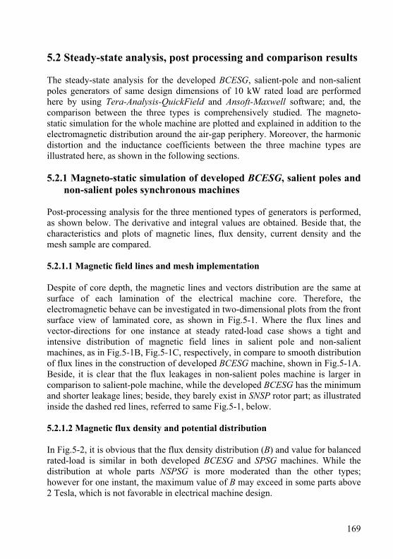
169
5.2 Steady-state analysis, post processing and comparison results The steady-state analysis for the developed BCESG, salient-pole and non-salient poles generators of same design dimensions of 10 kW rated load are performed here by using Tera-Analysis-QuickField and Ansoft-Maxwell software; and, the comparison between the three types is comprehensively studied. The magneto-static simulation for the whole machine are plotted and explained in addition to the electromagnetic distribution around the air-gap periphery. Moreover, the harmonic distortion and the inductance coefficients between the three machine types are illustrated here, as shown in the following sections. 5.2.1 Magneto-static simulation of developed BCESG, salient poles and
non-salient poles synchronous machines Post-processing analysis for the three mentioned types of generators is performed, as shown below. The derivative and integral values are obtained. Beside that, the characteristics and plots of magnetic lines, flux density, current density and the mesh sample are compared. 5.2.1.1 Magnetic field lines and mesh implementation Despite of core depth, the magnetic lines and vectors distribution are the same at surface of each lamination of the electrical machine core. Therefore, the electromagnetic behave can be investigated in two-dimensional plots from the front surface view of laminated core, as shown in Fig.5-1. Where the flux lines and vector-directions for one instance at steady rated-load case shows a tight and intensive distribution of magnetic field lines in salient pole and non-salient machines, as in Fig.5-1B, Fig.5-1C, respectively, in compare to smooth distribution of flux lines in the construction of developed BCESG machine, shown in Fig.5-1A. Beside, it is clear that the flux leakages in non-salient poles machine is larger in comparison to salient-pole machine, while the developed BCESG has the minimum and shorter leakage lines; beside, they barely exist in SNSP rotor part; as illustrated inside the dashed red lines, referred to same Fig.5-1, below. 5.2.1.2 Magnetic flux density and potential distribution In Fig.5-2, it is obvious that the flux density distribution (B) and value for balanced rated-load is similar in both developed BCESG and SPSG machines. While the distribution at whole parts NSPSG is more moderated than the other types; however for one instant, the maximum value of B may exceed in some parts above 2 Tesla, which is not favorable in electrical machine design.
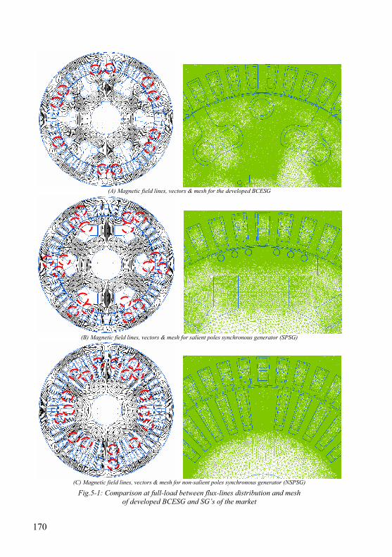
170
(A) Magnetic field lines, vectors & mesh for the developed BCESG
(B) Magnetic field lines, vectors & mesh for salient poles synchronous generator (SPSG)
(C) Magnetic field lines, vectors & mesh for non-salient poles synchronous generator (NSPSG)
Fig.5-1: Comparison at full-load between flux-lines distribution and mesh of developed BCESG and SG’s of the market
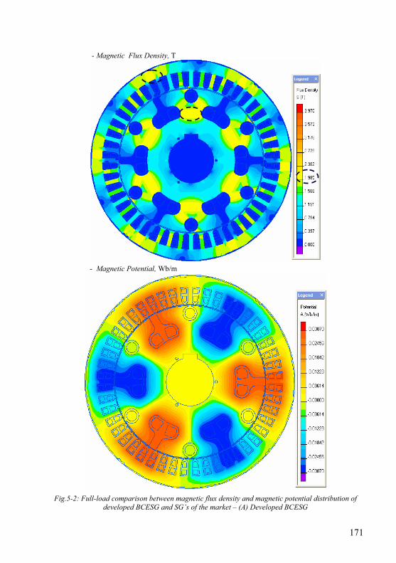
171
- Magnetic Flux Density, T
- Magnetic Potential, Wb/m
Fig.5-2: Full-load comparison between magnetic flux density and magnetic potential distribution of developed BCESG and SG’s of the market – (A) Developed BCESG
172
- Magnetic Flux Density, T
- Magnetic Potential, Wb/m
Fig.5-2: Full-load comparison between magnetic flux density and magnetic potential distribution of developed BCESG and SG’s of the market – (B) SPSG
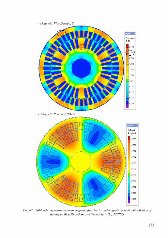
173
- Magnetic Flux Density, T
- Magnetic Potential, Wb/m
Fig.5-2: Full-load comparison between magnetic flux density and magnetic potential distribution of developed BCESG and SG’s of the market – (C) NSPSG
174
From other side, the magnetic potential distribution is uniform with similar values for the three presented types. The marked dashed circles on the respective plots of mentioned figure shows that the maximum values of B may reach to 1.985 Tesla (developed BCESG), Fig.5-2A, which is the same in SPSG, Fig.5-2B; whereas at some parts of NSPSG, B might reach for an instant to maximum value 2.3 Tesla, as shown in Fig.5-2C, above. These results fairly corresponding to the numerical results of analytical design sheet calculations, referred to chapter four, article 4.12. 5.2.1.3 Current density distribution and field intensity The maximum current density of stator windings in this design of single-phase BCESG is higher than the presented three-phase SPSG, as can be seen in Fig.5-3. However, the current density (J) can be reduced by increasing the cross-sectional area of conductors. Also, J could normally be moderated if a three-phase design of BCESG machine is applied. In addition, the plots in Fig.5-3A illustrates that the air-gap vector distribution of field-intensity of developed BCESG is gradient in amplitude along the pole arc with max value at pole center despite of the concentric slot at each pole face. This is approximately similar to the distribution in NSPSG, Fig.5-3C. Although the excitation in BCESG is self inductive type, the value of H in BCESG seems similar to that in SPSG machine, Fig.5-3B; where the excitation in the latest is of forced D.C. type. 5.2.2 Electromagnetic characteristics of developed BCESG and
comparison study For one instance at steady state operation, the magnetic potential, flux density, magnetic strength, energy density and harmonics of developed BCESG are theoretically investigated at 10 kW rated load and synchronous speed 1000 r.p.m by using QuickField simulation software. Comparison study is also made with SPSG and NSPSG as can be seen below. 5.2.2.1 Magnetic potential and flux density The plotted curves in Fig.5-4 represent the flux density and potential along the air-gap for three types of synchronous generators, designed for 6 poles with similar dimensions; where the whole air-gab periphery length is about 600 mm for each.
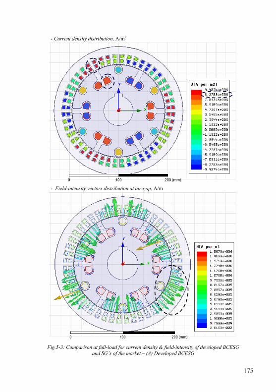
175
- Current density distribution, A/m2
- Field-intensity vectors distribution at air-gap, A/m
Fig.5-3: Comparison at full-load for current density & field-intensity of developed BCESG and SG’s of the market – (A) Developed BCESG
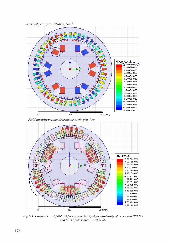
176
- Current density distribution, A/m2
- Field-intensity vectors distribution at air-gap, A/m
Fig.5-3: Comparison at full-load for current density & field-intensity of developed BCESG and SG’s of the market – (B) SPSG
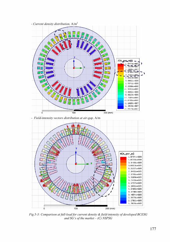
177
- Current density distribution, A/m2
- Field-intensity vectors distribution at air-gap, A/m
Fig.5-3: Comparison at full-load for current density & field-intensity of developed BCESG and SG’s of the market – (C) NSPSG
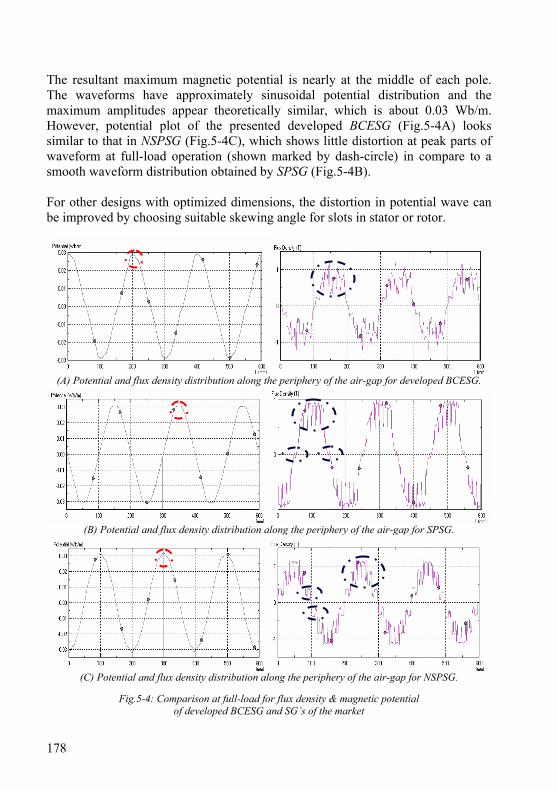
178
The resultant maximum magnetic potential is nearly at the middle of each pole. The waveforms have approximately sinusoidal potential distribution and the maximum amplitudes appear theoretically similar, which is about 0.03 Wb/m. However, potential plot of the presented developed BCESG (Fig.5-4A) looks similar to that in NSPSG (Fig.5-4C), which shows little distortion at peak parts of waveform at full-load operation (shown marked by dash-circle) in compare to a smooth waveform distribution obtained by SPSG (Fig.5-4B). For other designs with optimized dimensions, the distortion in potential wave can be improved by choosing suitable skewing angle for slots in stator or rotor.
(A) Potential and flux density distribution along the periphery of the air-gap for developed BCESG.
(B) Potential and flux density distribution along the periphery of the air-gap for SPSG.
(C) Potential and flux density distribution along the periphery of the air-gap for NSPSG.
Fig.5-4: Comparison at full-load for flux density & magnetic potential
of developed BCESG and SG’s of the market
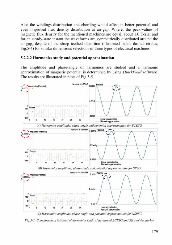
179
Also the windings distribution and chording would affect in better potential and even improved flux density distribution at air-gap. Where, the peak-values of magnetic flux density for the mentioned machines are equal, about 1.0 Tesla; and for an steady-state instant the waveforms are symmetrically distributed around the air-gap, despite of the sharp teethed distortion (illustrated inside dashed circles, Fig.5-4) for similar dimensions selections of three types of electrical machines. 5.2.2.2 Harmonics study and potential approximation The amplitude and phase-angle of harmonics are studied and a harmonic approximation of magnetic potential is determined by using QuickField software. The results are illustrated in plots of Fig.5-5.
(A) Harmonics amplitude, phase-angle and potential approximation for BCESG
(B) Harmonics amplitude, phase-angle and potential approximation for SPSG
(C) Harmonics amplitude, phase-angle and potential approximation for NSPSG
Fig.5-5: Comparison at full-load of harmonics study of developed BCESG and SG’s of the market
Potential
0.00024
0.0325
-0.032Linear approximationHarmonic approximation
Potential
6.11e-6
0.03076
-0.0308Linear approximationHarmonic approximation
Potential
3.27e-6
0.02884
-0.0288Linear approximationHarmonic approximation
Amplitudes (Potential)
Phases
0.02731
0180°
0°
-180°1 5 10 15 20 25 30
Harmonic 0: 3.271e-6
Amplitudes (Potential)
Phases
0.03038
0180°
0°
-180°1 5 10 15 20 25 30
Harmonic 0: 6.1148e-6
Amplitudes (Potential)
Phases
0.03124
0180°
0°
-180°1 5 10 15 20 25 30
Harmonic 0: 0.00024006
180
The 3rd harmonics is 0.02731 for developed BCESG machine at phase angle 78.4°, which considers as the minimum value in compare with 3rd harmonics values of the other two machines (SPSG & NSPSG). The amplitude and phase angles can be seen in Fig.5-5 A, B & C, (marked with dashed circle). In addition, Table C-1 at Appendix C.5 shows detailed harmonics values till 17th harmonics. On the other hand, the waveform of potential distribution that is already plotted in Fig.5-4 is compared now with harmonic approximation for each mentioned types of synchronous generators, as illustrated in Fig.5-5 (marked by dashed ellipse). 5.2.2.3 Field strength and energy density In similar study, the average amount of energy density for similar volume size of the presented three machines types is approximately similar and nearly equal to 2×10⁵ J/m3, as can be seen in waveforms of Fig.5-6, below (marked in dashed circle). While, the pulsed distributions of resultant magnetic strength seem fairly gradient and have approximately similar peak values, up to about 2.5×10⁵ A/m. Also, the strength’s plot appears more uniform in distribution along the length of air-gap for SPSG and NSPSG, referred to Fig.5-6B and Fig.5-6C, respectively. However, the dedicated hollow at poles’ centers for latest both machines (marked in dashed ellipse) does not exist in case of developed BCESG, as seen in characteristics at Fig.5-6A; then the amplitudes of magnetic potential are gradually and continuously ascending or descending. 5.2.3 Inductances and magnetic coefficients The incremental self and mutual inductances at one instance of steady-state rated-load operation are calculated by using Maxwell simulation software. More, the inductive coupling coefficient of the developed BCESG machine is investigated and compared with the other generators (SPSG, NSPSG). From the post processing results shown in Appendix C.6 (layout of Maxwell static simulation), it is clear that despite of self excitation, the maximum self inductance of field winding (Wrm) of BCESG is about 105 mH, which is approximately similar to that in NSPSG (98 mH), but less than the self inductance of exciter field winding (154 mH), which is force excited by external D.C. power supply. However, the mutual inductance between rotor main field winding (Wrm or Exciter winding) and stator capacitor-exciter winding (Wc) or phase winding (Ph_A) seems equal for both developed BCESG and SPSG (approximately 17 mH). It is larger than mutual inductance in NSPSG (approximately 13 mH, Appendix C.6). Above that, the inductive coupling coefficient for brushless self-excited generator is 0.71 which is approximately similar to that in the other both D.C. exciter salient and non-salient pole synchronous generators, those have coupling coefficient nearly about 0.79.
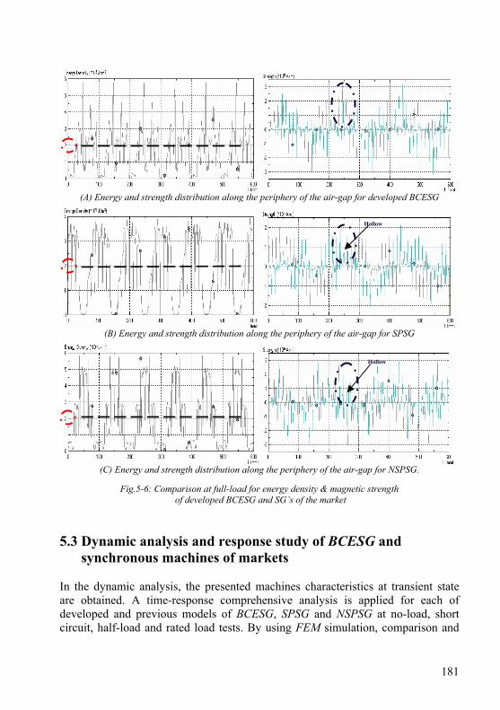
181
(A) Energy and strength distribution along the periphery of the air-gap for developed BCESG
(B) Energy and strength distribution along the periphery of the air-gap for SPSG
(C) Energy and strength distribution along the periphery of the air-gap for NSPSG.
Fig.5-6: Comparison at full-load for energy density & magnetic strength
of developed BCESG and SG’s of the market 5.3 Dynamic analysis and response study of BCESG and
synchronous machines of markets In the dynamic analysis, the presented machines characteristics at transient state are obtained. A time-response comprehensive analysis is applied for each of developed and previous models of BCESG, SPSG and NSPSG at no-load, short circuit, half-load and rated load tests. By using FEM simulation, comparison and
Hollow
Hollow
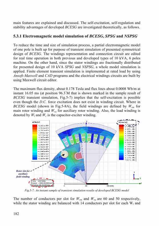
182
main features are explained and discussed. The self-excitation, self-regulation and stability advantages of developed BCESG are investigated theoretically, as follows. 5.3.1 Electromagnetic model simulation of BCESG, SPSG and NSPSG To reduce the time and size of simulation process, a partial electromagnetic model of one pole is built up for purpose of transient simulation of presented symmetrical design of BCESG. The windings representation and connection circuit are edited for real time operation in both previous and developed types of 10 kVA, 6 poles machine. On the other hand, since the stator windings are fractionally distributed for presented design of 10 kVA SPSG and NSPSG, a whole model simulation is applied. Finite element transient simulation is implemented at rated load by using Ansoft-Maxwell and CAD programs and the electrical windings circuits are built by using Maxwell circuit editor. The maximum flux density, about 0.178 Tesla and flux lines about 0.0008 Wb/m at instant 16.05 ms (at position 96.3°M that is shown marked in the sample result of BCESG transient simulation, Fig.5-7) implies that the self-excitation is possible even though the D.C. force excitation does not exist in winding circuit. Where in BCESG model (shown in Fig.5-8A), the field windings are defined by Wrm for main rotor winding and Wra for auxiliary rotor winding. Also, the load winding is denoted by Wl and Wc is the capacitor-exciter winding.
Fig.5-7: An instant sample of transient simulation results of developed BCESG model The number of conductors per slot for Wrm and Wra are 60 and 50 respectively, while the stator winding are balanced with 14 conductors per slot for each Wl and
Rotor slot for auxiliary
field winding

183
Wc, separately. The coil pitch is 6 slots as already determined from theoretical design calculations, chapter four. In addition, the machine windings are connected to diodes, capacitors, pure resistive load; and measurement tools are inserted on the electrical circuit of the model without any D.C. exciter source, as in Fig.5-8B.
Fig.5-8: Building up an electromagnetic model of developed BCESG for purpose of transient simulation
+ve
-ve
BCESG One Pole Electro-magnetic Model
ROTOR
STATOR
Representation of half-wave rectifier circuit for rotor windings in previous BCESG
(B) Windings connection diagram for developed BCESG model, Circuit-Editor
(A) Layout of one-pole electromagnetic model of developed BCESG, Maxwell

184
In comparison, the construction and circuit connection of previous BCESG model is similar to developed BCESG. Also, the self-excitation is existed, as shown in sample simulation result, Fig.5-9; although, the rotor circuit is of half-wave rectification, as can be seen in Fig.5-10.
Fig.5-9: An instant sample of transient simulation results of previous BCESG model
Fig.5-10: Windings connection diagram for Previous BCESG, using Maxwell circuit editor
However in the previous BCESG and at certain instants, the concentric flux lines around the rotor slot of auxiliary winding (simulation result, Fig.5-9) increase the eddy currents and disturb the field distribution at certain parts of the machine, in
Rotor slot for auxiliary
field winding
Representation of half-wave rectifier circuit for rotor windings in
previous BCESG
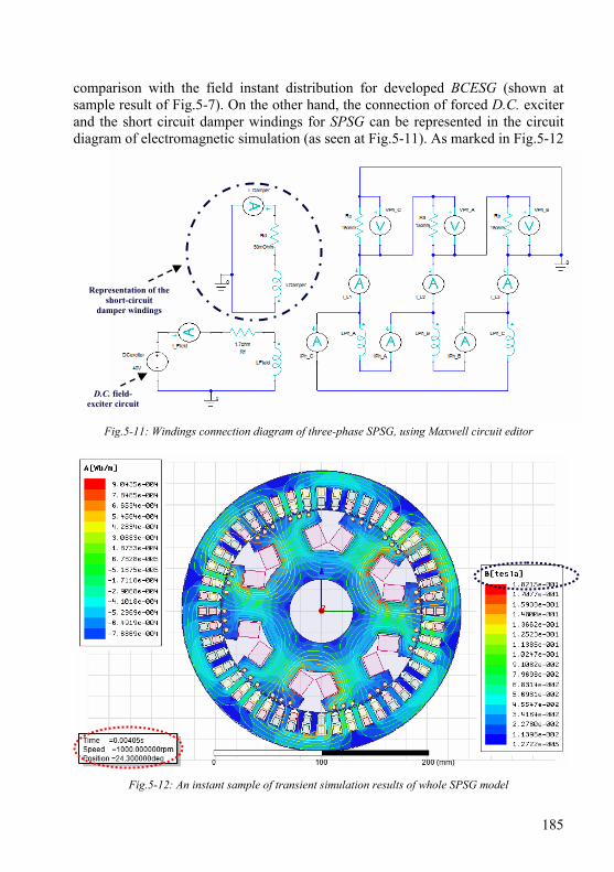
185
comparison with the field instant distribution for developed BCESG (shown at sample result of Fig.5-7). On the other hand, the connection of forced D.C. exciter and the short circuit damper windings for SPSG can be represented in the circuit diagram of electromagnetic simulation (as seen at Fig.5-11). As marked in Fig.5-12
Fig.5-11: Windings connection diagram of three-phase SPSG, using Maxwell circuit editor
Fig.5-12: An instant sample of transient simulation results of whole SPSG model
Representation of the short-circuit
damper windings
D.C. field- exciter circuit
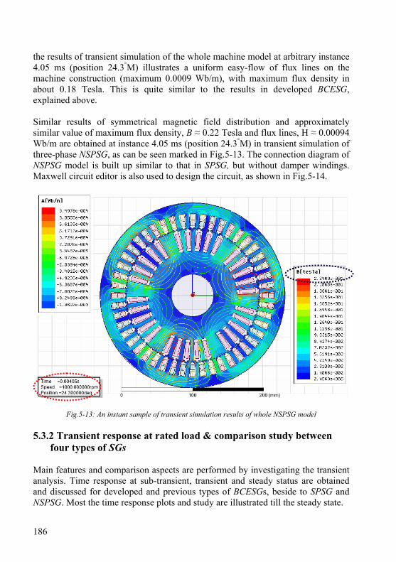
186
the results of transient simulation of the whole machine model at arbitrary instance 4.05 ms (position 24.3°M) illustrates a uniform easy-flow of flux lines on the machine construction (maximum 0.0009 Wb/m), with maximum flux density in about 0.18 Tesla. This is quite similar to the results in developed BCESG, explained above. Similar results of symmetrical magnetic field distribution and approximately similar value of maximum flux density, B ≈ 0.22 Tesla and flux lines, H ≈ 0.00094 Wb/m are obtained at instance 4.05 ms (position 24.3°M) in transient simulation of three-phase NSPSG, as can be seen marked in Fig.5-13. The connection diagram of NSPSG model is built up similar to that in SPSG, but without damper windings. Maxwell circuit editor is also used to design the circuit, as shown in Fig.5-14.
Fig.5-13: An instant sample of transient simulation results of whole NSPSG model 5.3.2 Transient response at rated load & comparison study between
four types of SGs Main features and comparison aspects are performed by investigating the transient analysis. Time response at sub-transient, transient and steady status are obtained and discussed for developed and previous types of BCESGs, beside to SPSG and NSPSG. Most the time response plots and study are illustrated till the steady state.

187
Fig.5-14: Windings connection diagram of three-phase NSPSG, using Maxwell circuit editor
5.3.2.1 Sub-transient, transient and steady statuses By using Ansoft-Maxwell software, the time response analysis for 10 kW, 1000 r.p.m developed BCESG (shown in the model of Fig.5-8) is applied at rated-load. The induced voltages at load winding (Wl), main-field winding (Wrm) and auxiliary-field winding (Wra), beside Flux linkage of Wrm and Wra and load current in Wl winding are plotted and illustrated for a time period of about 520 ms, as can be seen in Fig.5-15. Similar scheme is achieved for previous BCESG model, at rated load and the results are plotted in Fig.5-16, shown below. From plotted results, it is obvious that the main field winding (FluxLinkage-Wrm) is gradually built in proportional to a nonlinear B-H curve of core material, starting from lower residual magnetism up to fixed strong level (marked by dotted ellipse, Fig.s 5-15 & 5-16). This main magnetic field is higher (4 Wb) at developed BCESG in compare to its value (1.5 Wb) at previous BCESG model. Whereas, it is somehow less than the main excitation field level (FluxLinkage-Field) in SNSP and approximately equal to field level in NSPSG models, as can be seen in Fig.5-17 and Fig.5-18, respectively; although, the excitation in BCESG is independently self created, without enhancements of any external D.C. excitation.
D.C. field- exciter circuit
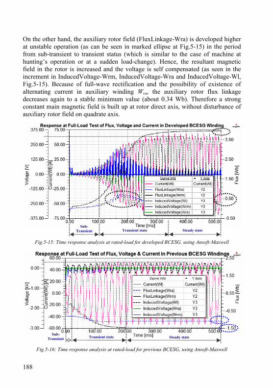
188
On the other hand, the auxiliary rotor field (FluxLinkage-Wra) is developed higher at unstable operation (as can be seen in marked ellipse at Fig.5-15) in the period from sub-transient to transient status (which is similar to the case of machine at hunting’s operation or at a sudden load-change). Hence, the resultant magnetic field in the rotor is increased and the voltage is self compensated (as seen in the increment in InducedVoltage-Wrm, InducedVoltage-Wra and InducedVoltage-Wl, Fig.5-15). Because of full-wave rectification and the possibility of existence of alternating current in auxiliary winding Wra, the auxiliary rotor flux linkage decreases again to a stable minimum value (about 0.34 Wb). Therefore a strong constant main magnetic field is built up at rotor direct axis, without disturbance of auxiliary rotor field on quadrate axis.
Fig.5-15: Time response analysis at rated-load for developed BCESG, using Ansoft-Maxwell
Fig.5-16: Time response analysis at rated-load for previous BCESG, using Ansoft-Maxwell
Transient state Steady state Sub-
Transient
Transient state Steady state Sub-
Transient
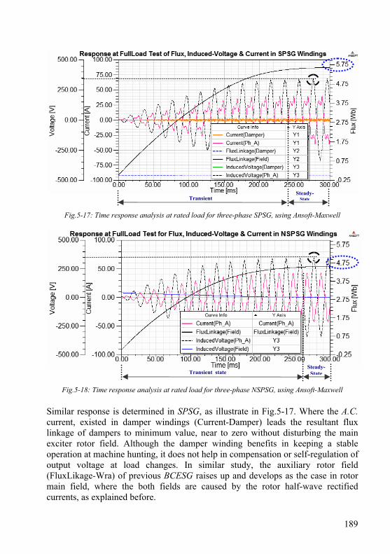
189
Fig.5-17: Time response analysis at rated load for three-phase SPSG, using Ansoft-Maxwell
Fig.5-18: Time response analysis at rated load for three-phase NSPSG, using Ansoft-Maxwell Similar response is determined in SPSG, as illustrate in Fig.5-17. Where the A.C. current, existed in damper windings (Current-Damper) leads the resultant flux linkage of dampers to minimum value, near to zero without disturbing the main exciter rotor field. Although the damper winding benefits in keeping a stable operation at machine hunting, it does not help in compensation or self-regulation of output voltage at load changes. In similar study, the auxiliary rotor field (FluxLikage-Wra) of previous BCESG raises up and develops as the case in rotor main field, where the both fields are caused by the rotor half-wave rectified currents, as explained before.
Steady-StateTransient
Steady-StateTransient state
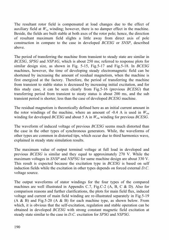
190
The resultant rotor field is compensated at load changes due to the effect of auxiliary field at Wra winding; however, there is no damper effect in the machine. Beside, the fields are built stable at both axes of the rotor pole; hence, the direction of resultant maximum field slights a little away from direct axis of pole construction in compare to the case in developed BCESG or SNSP, described above. The period of transferring the machine from transient to steady state are similar in BCESG, SPSG and NSPAG, which is about 250 ms; referred to response plots for similar design size, as shown in Fig. 5-15, Fig.5-17 and Fig.5-18. In BCESG machines, however, the time of developing steady electromagnetic field can be shortened by increasing the amount of residual magnetism, when the machine is first energized at the factory. Therefore, the period of transferring the machine from transient to stable status is decreased by increasing initial excitation, and for this study case, it can be seen clearly from Fig.5-16 (previous BCESG) that transferring period from transient to steaty status is about 200 ms, and the sub transient period is shorter; less than the case of developed BCESG machine. The residual magnetism is theoretically defined here as an initial current amount in the rotor windings of the machine, where an amount of -0.4 A is used in Wrm winding for developed BCESG and about 5 A in Wrm winding for previous BCESG. The waveform of induced voltage of previous BCESG seems much distorted than the case in the other types of synchronous generators. While, the waveforms of other types are common in distorted tips, which occur due to third harmonics wave, explained in steady state simulation results. The maximum value of output terminal voltage at full load in developed and previous BCESG is similar and they equal to approximately 270 V. While the maximum voltages in SNSP and NSPSG for same machine design are about 330 V. This result is expected because the excitation type in BCESG is based on self induction fields while the excitation in other types depends on forced external D.C. voltage source. The output waveforms of stator windings for the four types of the compared machines are well illustrated in Appendix C.7, Fig.C-2 (A, B, C & D). Also for comparison reasons and further clarifications, the plots for main field flux, induced voltage and current of main field winding are re-illustrated separately in Fig.5-19 (A & B) and Fig.5-20 (A & B) for each machine type, as shown below. From which, it is obvious that the self-excitation, regulation and stable operation can be obtained in developed BCESG with strong constant magnetic field excitation at steady state similar to the case in D.C. excitation for SPSG and NSPSG.
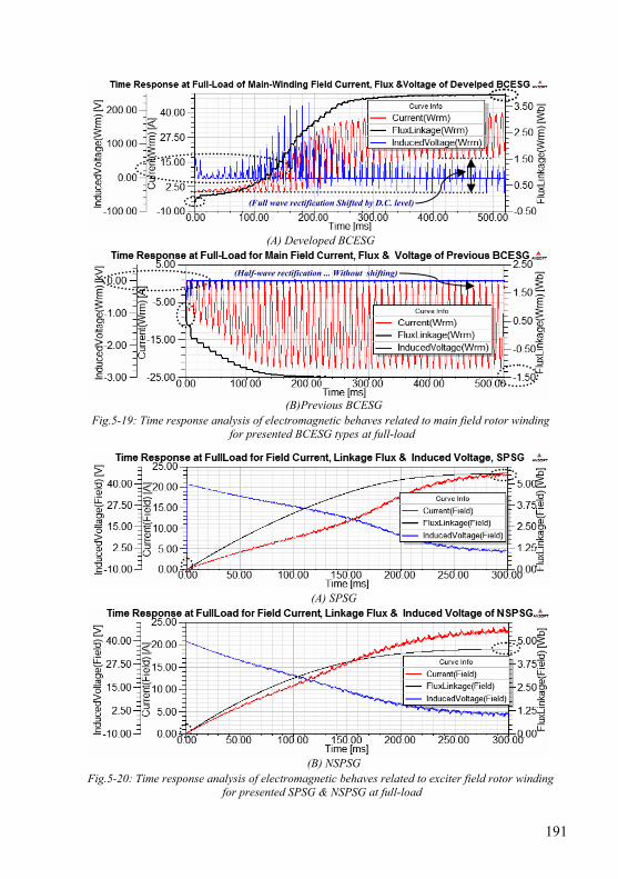
191
(A) Developed BCESG
(B)Previous BCESG
Fig.5-19: Time response analysis of electromagnetic behaves related to main field rotor winding for presented BCESG types at full-load
(A) SPSG
(B) NSPSG
Fig.5-20: Time response analysis of electromagnetic behaves related to exciter field rotor winding for presented SPSG & NSPSG at full-load
(Full wave rectification Shifted by D.C. level)
(Half-wave rectification ... Without shifting)
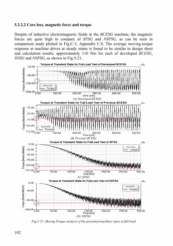
192
5.3.2.2 Core loss, magnetic force and torque Despite of inductive electromagnetic fields in the BCESG machine, the magnetic forces are quite high in compare of SPSG and NSPSG, as can be seen in comparison study plotted in Fig.C-3, Appendix C.8. The average moving-torque response at machine drives at steady status is found to be similar to design sheet and calculation results, approximately 110 Nm for each of developed BCESG, SNSG and NSPSG, as shown in Fig.5-21.
(A) Developed BCESG
(B) Previous BCESG
(C) SPSG
(D) NSPSG
Fig.5-21: Moving Torque analysis of the presented machines types at full-load
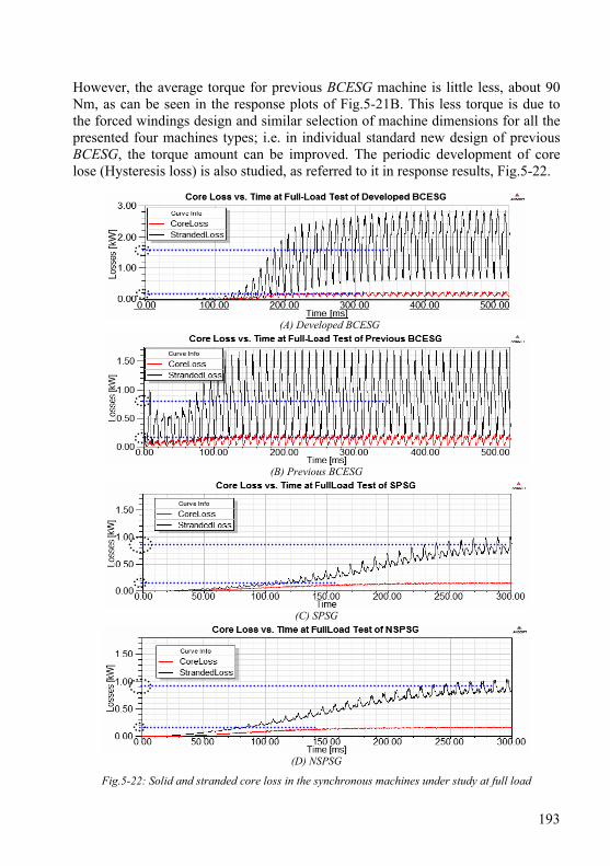
193
However, the average torque for previous BCESG machine is little less, about 90 Nm, as can be seen in the response plots of Fig.5-21B. This less torque is due to the forced windings design and similar selection of machine dimensions for all the presented four machines types; i.e. in individual standard new design of previous BCESG, the torque amount can be improved. The periodic development of core lose (Hysteresis loss) is also studied, as referred to it in response results, Fig.5-22.
(A) Developed BCESG
(B) Previous BCESG
(C) SPSG
(D) NSPSG
Fig.5-22: Solid and stranded core loss in the synchronous machines under study at full load

194
So, in these machines under discussion of size 10 kW, 1000 r.p.m, the average core loss at full-load for developed BCESG (about 1500 W) is higher than the core loss of other types (where it reaches to about 900W); although, the stranded loss is approximately equal for all the four types of the mentioned synchronous generators (in which the stranded loss is about 150 W). However, the core losses could be minimized by selecting steel material of lower specific loss. In the analysis study above, choosing solid core loss specifies that the eddy currents effect in the winding is considered. On the other hand, in stranded core loss only D.C. resistance would have been calculated and no A.C. effects in the coil would have been considered. However, the stranded loss is appropriate when the skin depth is much larger than the stranded conductor thickness, also the induced eddy effects in the core is calculated in either case [Ref.19, chapter four]. 5.3.2.3 Self and mutual inductances at transient state The values of self inductances, mutual inductances and also magnetic coupling coefficients at one instance of steady state rated-load operation is already investigated, article 5.2.3. However, these inductive parameters have changeable periodic behave which is important to be detected and discussed, as can be seen in the following. Upon the transient simulation results shown for developed BCESG in time-response plots, Fig.5-23, the self inductance seems approximately constant for each windings Wl, Wc, Wrm and Wra and have the highest value in compare to mutual inductances, as expected. Beside, the mutual inductances are varying in uniform sinusoidal periods with fixed time delay between related waves that depends on the designed position of windings in the rotor and space phase shift of windings in the stator. In addition to that, it is realized a considerable constant mutual inductance value between both stator windings in developed BCESG, despite of 90 °E space phase-shift in construction between axes of Wl and Wc windings. Whereas, the mutual inductances between stator windings are very small and also a small mutual inductance between rotor windings with same sinusoidal behave is existed. These inductances behave are almost similar to that in other presented machines types, as can be seen in Fig.C-4, Fig.C-5, and Fig.C-6, Appendix C.9 for previous BCESG, SPSG and NSPSG, respectively. However, the values of mutual inductance between adjacent windings in separately stator or rotor side tends to least values, almost zero; beside, all the mutual inductances related to damper winding in SPSG are very little, given in µH.
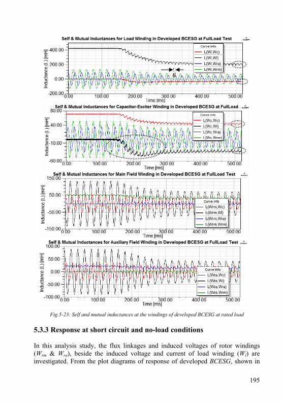
195
Fig.5-23: Self and mutual inductances at the windings of developed BCESG at rated load 5.3.3 Response at short circuit and no-load conditions In this analysis study, the flux linkages and induced voltages of rotor windings (Wrm & Wra), beside the induced voltage and current of load winding (Wl) are investigated. From the plot diagrams of response of developed BCESG, shown in
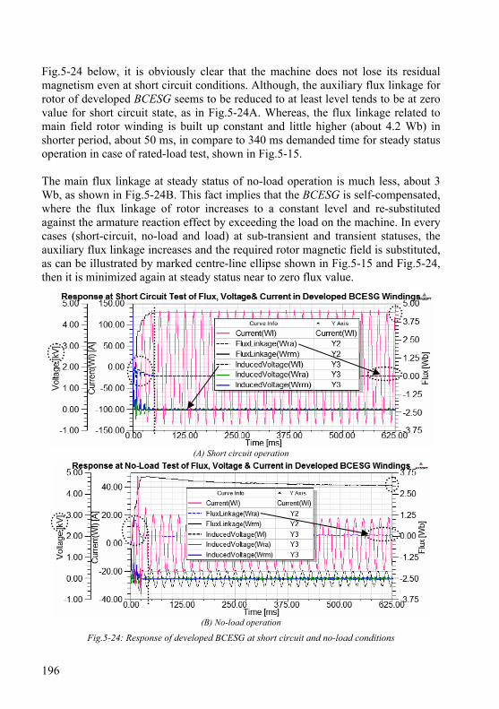
196
Fig.5-24 below, it is obviously clear that the machine does not lose its residual magnetism even at short circuit conditions. Although, the auxiliary flux linkage for rotor of developed BCESG seems to be reduced to at least level tends to be at zero value for short circuit state, as in Fig.5-24A. Whereas, the flux linkage related to main field rotor winding is built up constant and little higher (about 4.2 Wb) in shorter period, about 50 ms, in compare to 340 ms demanded time for steady status operation in case of rated-load test, shown in Fig.5-15. The main flux linkage at steady status of no-load operation is much less, about 3 Wb, as shown in Fig.5-24B. This fact implies that the BCESG is self-compensated, where the flux linkage of rotor increases to a constant level and re-substituted against the armature reaction effect by exceeding the load on the machine. In every cases (short-circuit, no-load and load) at sub-transient and transient statuses, the auxiliary flux linkage increases and the required rotor magnetic field is substituted, as can be illustrated by marked centre-line ellipse shown in Fig.5-15 and Fig.5-24, then it is minimized again at steady status near to zero flux value.
(A) Short circuit operation
(B) No-load operation
Fig.5-24: Response of developed BCESG at short circuit and no-load conditions
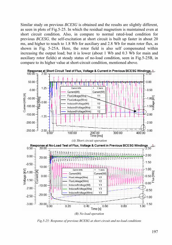
197
Similar study on previous BCESG is obtained and the results are slightly different, as seen in plots of Fig.5-25. In which the residual magnetism is maintained even at short circuit condition. Also, in compare to normal rated-load condition for previous BCESG, the self-excitation at short circuit is built up faster in about 20 ms, and higher to reach to 1.8 Wb for auxiliary and 2.8 Wb for main rotor flux, as shown in Fig. 5-25A. Here, the rotor field is also self compensated within increasing the output load; but it is lower (about 1 Wb and 0.3 Wb for main and auxiliary rotor fields) at steady status of no-load condition, seen in Fig.5-25B, in compare to its higher value at short-circuit condition, mentioned above.
(A) Short circuit operation
(B) No-load operation
Fig.5-25: Response of previous BCESG at short circuit and no-load conditions
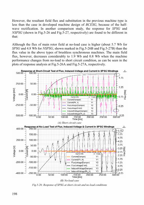
198
However, the resultant field flux and substitution in the previous machine type is less than the case in developed machine design of BCESG, because of the half-wave rectification. In another comparison study, the response for SPSG and NSPSG (shown in Fig.5-26 and Fig.5-27, respectively) are found to be different in that: Although the flux of main rotor field at no-load case is higher (about 5.7 Wb for SPSG and 4.8 Wb for NSPSG, shown marked in Fig.5-26B and Fig.5-27B) than the flux value in the above types of brushless synchronous machines. The main field flux, however, decreases considerably to 1.9 Wb and 0.8 Wb when the machine performance changes from no-load to short circuit condition, as can be seen in the plots of response analysis at Fig.5-26A and Fig.5-27A, respectively.
(A) Short circuit case
(B) No-load case
Fig.5-26: Response of SPSG at short circuit and no-load conditions
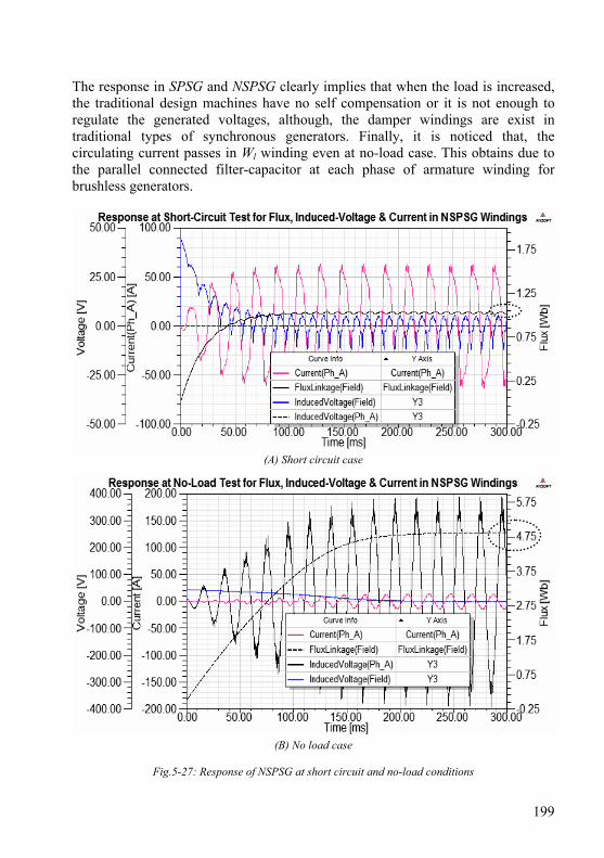
199
The response in SPSG and NSPSG clearly implies that when the load is increased, the traditional design machines have no self compensation or it is not enough to regulate the generated voltages, although, the damper windings are exist in traditional types of synchronous generators. Finally, it is noticed that, the circulating current passes in Wl winding even at no-load case. This obtains due to the parallel connected filter-capacitor at each phase of armature winding for brushless generators.
(A) Short circuit case
(B) No load case
Fig.5-27: Response of NSPSG at short circuit and no-load conditions

200
5.4 Discussion of main features and importance of developed BCESG
Upon the simulation results, transient response analysis and comparison study presented in this chapter, it can be considered that the characteristics and construction of BCESG with developed rotor design (named salient and non-salient pole, SNSP) are combined between the characteristics of SPSG and NSPSG machines. Moreover, the following improved features have been detected: - The leakage flux lines at steady state condition are less and shorter than that in the other traditional design of synchronous generators, illustrated in article 5.2.1.1, Fig.5.1A. Also, the 3rd harmonics at rated-load obtained in developed BCESG with balanced stator windings is less than that in SPSG and NSPSG with fractional stator windings and same machine dimensions, as explained in article 5.2.2.2. - For same machine size, the average amount of energy density is the approximately equal for single-phase developed BCESG or three-phase SPSG and NSPSG types, as described in article 5.2.2.3, Fig.5-6. Beside, the amplitude of magnetic potential along the air-gap length is gradually and continuously distributed. Hence, the machine of developed BCESG is expected to have more stable operation in compare to the other mentioned types of generators. - The self excitation is possible in developed BCESG without the existence of any external D.C. or A.C. rotating exciters, as seen in the electromagnetic model simulation at article 5.3.1, Fig.5-7; and by comparing with simulation results of previous model, shown in Fig.5-9, the flux lines distribution are found to be more straight and uniform in developed machine. - In comparing between the steady status of developed BCESG at no-load, rated-load and short circuit conditions, shown in Fig.5-24B, Fig.5-15 and Fig.5-24A, respectively. It is obvious that the self compensation of rotor main field is occurred at increasing of load; because the rotor main flux linkage is increased as the generator output develops form no-load up to short circuit state. - As can be seen in response analysis at Fig.5-28A and Fig.5-28C, the transient behaves of rotor auxiliary winding in developed BCESG is similar to that for damper winding in synchronous generators, where the A.C. component is existed in both mentioned windings. This is different from previous BCESG in that only a D.C. half-wave component is existed (shown in Fig.5-28B).
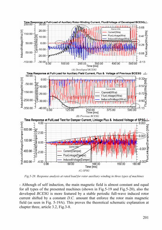
201
(A) Developed BCESG
(B) Previous BCESG
(C) SPSG
Fig.5-28: Response analysis at rated load for rotor auxiliary winding in three types of machines - Although of self induction, the main magnetic field is almost constant and equal for all types of the presented machines (shown in Fig.5-19 and Fig.5-20), also the developed BCESG is more featured by a stable periodic full-wave induced rotor current shifted by a constant D.C. amount that enforce the rotor main magnetic field (as seen in Fig. 5-19A). This proves the theoretical schematic explanation at chapter three, article 3.2, Fig.3-8.
202
- Since the rotor main field is kept sustained at increased load till short-circuit case (seen in Fig.5-24A), it can be deduced that the residual magnetism in developed BCESG is maintained even at short-circuit condition, even though the auxiliary flux and induced load voltage reduces to zero. - Above all, the rotor auxiliary flux tends to lower value near zero at steady state operation; because it is alternating and encountered a high reluctance faced on orthogonal construction of SNSP rotor. However, the advantage of auxiliary rotor winding in developed BCESG appears only at unstable operation of the machine, where the flux is instantly increased (as seen in Fig.5-28) by interacting with armature reaction fields, and hence it substitutes the lack of main magnetic field in the rotor. This would provide a stable operation of the machine, even at sub-transient or transient statuses.

203
Chapter 6
Prototype Machine and Experimental Results
The results of the presented theoretical design and simulation are practically investigated by implementing experimental tests on general prototype machine of size and design on 10 kW, 1000 r.p.m. of brushless self-excited and self-regulated synchronous generator; which is re-constructed, assembled and tested by the author in the laboratories of Kassel University with helps of the university departments. Although, the experimental tests for multi-phase generator, pole-changes, different stator windings connections, phase angle and load types changes are encountered by some limitations; the no-load and load characteristics of developed BCESG model and also previous model are, however, practically determined and compared at half-full load. In addition, the main features are fairly proved. In the following sections, the prototype description and practical tests’ results are illustrated by characteristics curves and also by display of some measuring devices screen, where the driving-torque, speed, induced voltages, currents, power and harmonics are measured for each stator and rotor windings and also the waveforms display are plotted. 6.1 Manufacturing general prototype of developed BCESG
machine The prototype machine is converted from commercial squirrel-cage industrial motor of size 11 kW, 8 poles to a synchronous generator of size 10 kW, 6 poles with new constructed wound-rotor, as shown in Fig.6-1 A,B,C,D,E and F. The new laminated rotor is manufactured in the factory and the windings of stator and rotor are re-wounded with new arrangements. This prototype is built with cables extensions for external connections and complete data measurements, as described in the following sections. The step by step manufacturing details is briefly illustrated in the documentation-photos, listed in Appendix D.1. 6.1.1 Stator and SNSP rotor core The stator core is laminated with electrical steel laminations of material type M400-50A. The number of slots is 48. The core outer and inner diameters are 263 and 191 mm, respectively.
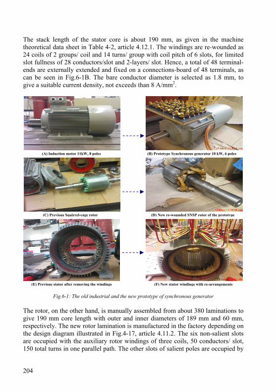
204
The stack length of the stator core is about 190 mm, as given in the machine theoretical data sheet in Table 4-2, article 4.12.1. The windings are re-wounded as 24 coils of 2 groups/ coil and 14 turns/ group with coil pitch of 6 slots, for limited slot fullness of 28 conductors/slot and 2-layers/ slot. Hence, a total of 48 terminal-ends are externally extended and fixed on a connections-board of 48 terminals, as can be seen in Fig.6-1B. The bare conductor diameter is selected as 1.8 mm, to give a suitable current density, not exceeds than 8 A/mm2.
Fig.6-1: The old industrial and the new prototype of synchronous generator The rotor, on the other hand, is manually assembled from about 380 laminations to give 190 mm core length with outer and inner diameters of 189 mm and 60 mm, respectively. The new rotor lamination is manufactured in the factory depending on the design diagram illustrated in Fig.4-17, article 4.11.2. The six non-salient slots are occupied with the auxiliary rotor windings of three coils, 50 conductors/ slot, 150 total turns in one parallel path. The other slots of salient poles are occupied by
(A) Induction motor 11kW, 8 poles (B) Prototype Synchronous generator 10 kW, 6 poles
(E) Previous stator after removing the windings (F) New stator windings with re-arrangements
(C) Previous Squirrel-cage rotor (D) New re-wounded SNSP rotor of the prototype
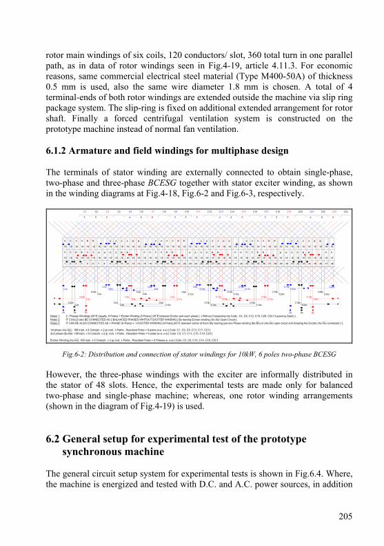
205
rotor main windings of six coils, 120 conductors/ slot, 360 total turn in one parallel path, as in data of rotor windings seen in Fig.4-19, article 4.11.3. For economic reasons, same commercial electrical steel material (Type M400-50A) of thickness 0.5 mm is used, also the same wire diameter 1.8 mm is chosen. A total of 4 terminal-ends of both rotor windings are extended outside the machine via slip ring package system. The slip-ring is fixed on additional extended arrangement for rotor shaft. Finally a forced centrifugal ventilation system is constructed on the prototype machine instead of normal fan ventilation. 6.1.2 Armature and field windings for multiphase design The terminals of stator winding are externally connected to obtain single-phase, two-phase and three-phase BCESG together with stator exciter winding, as shown in the winding diagrams at Fig.4-18, Fig.6-2 and Fig.6-3, respectively.
Fig.6-2: Distribution and connection of stator windings for 10kW, 6 poles two-phase BCESG However, the three-phase windings with the exciter are informally distributed in the stator of 48 slots. Hence, the experimental tests are made only for balanced two-phase and single-phase machine; whereas, one rotor winding arrangements (shown in the diagram of Fig.4-19) is used. 6.2 General setup for experimental test of the prototype
synchronous machine The general circuit setup system for experimental tests is shown in Fig.6.4. Where, the machine is energized and tested with D.C. and A.C. power sources, in addition
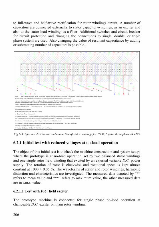
206
to full-wave and half-wave rectification for rotor windings circuit. A number of capacitors are connected externally to stator capacitor-windings, as an exciter and also to the stator load-winding, as a filter. Additional switches and circuit breaker for circuit protection and changing the connections to single, double, or triple phase system are used. Also changing the value of resultant capacitance by adding or subtracting number of capacitors is possible.
?
Fig.6-3: Informal distribution and connection of stator windings for 10kW, 6 poles three-phase BCESG 6.2.1 Initial test with reduced voltages at no-load operation The object of this initial test is to check the machine construction and system setup; where the prototype is at no-load operation, set by two balanced stator windings and one single rotor field winding that excited by an external variable D.C. power supply. The rotation of rotor is clockwise and rotational speed is kept almost constant at 1000 ± 0.05 %. The waveforms of stator and rotor windings, harmonic distortion and characteristics are investigated. The measured data denoted by “*” refers to mean value and “**” refers to maximum value, the other measured data are in r.m.s. value. 6.2.1.1 Test with D.C. field exciter The prototype machine is connected for single phase no-load operation at changeable D.C. exciter on main rotor winding.
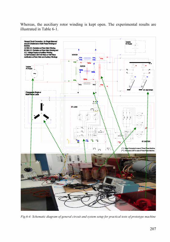
207
Whereas, the auxiliary rotor winding is kept open. The experimental results are illustrated in Table 6-1.
Fig.6-4: Schematic diagram of general circuit and system setup for practical tests of prototype machine
ST. EXCITER
C4
C5
C6
CONT 2
CB
4
CB
6
CB
5
~220-240 V
W Xs
W Xe
W Cs
ST. LOAD
W AsW Ms
W Bs
L3 L2 L1
W AeW Me
W BeW Ce
C1C2C3
CB3
CB2
CB1 CONT 1
N
~220-240 V
W Ae W AsW Xs
W Ce
W Me W Ms
W Xe
W Bs
W Be
STATOR
WrMsWrMe
WrAs
WrAe
ROTOR
W Cs
General Circuit Connection - for Single Balancedand 2/3 Unbalanced or Multi Phase Windings ofBCESG:A) With D.C. Excitation at Rotor Main Winding.B) With D.C. Excitation at Rotor Main Winding andA.C. Voltage Supply at Auxilliary Winding.C) Self Excitation with Full-Wave or Half-Waverectification at Rotor Main and Auxiliary Windings
VariableDC Supply
Changeable Single orMulti-Pahse Loads
~230 V
~
VariableAC Supply
( * ) : Stays Connected in case of Three Phase Machine.
( ** ) : Removed JUST in case of Three Phase Machine.( * )
( * )
( ** )
RT. RECTIFIER
D1 D2
D3 D4
T1
T1
T2
T2
T4
T4 , T3
T3
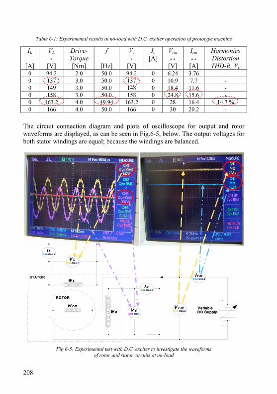
208
Table 6-1: Experimental results at no-load with D.C. exciter operation of prototype machine
IL
[A]
VL
* [V]
Drive- Torque [Nm]
f
[Hz]
Vc
* [V]
Ic [A]
Vrm
* * [V]
Irm
* * [A]
Harmonics Distortion THD-R, VL
0 94.2 2.0 50.0 94.2 0 6.24 3.76 - 0 137 3.0 50.0 137 0 10.9 7.7 - 0 149 3.0 50.0 148 0 18.4 11.6 - 0 158 3.0 50.0 158 0 24.8 15.6 - 0 163.2 4.0 49.94 163.2 0 28 16.4 14.7 % 0 166 4.0 50.0 166 0 30 20.2 -
The circuit connection diagram and plots of oscilloscope for output and rotor waveforms are displayed, as can be seen in Fig.6-5, below. The output voltages for both stator windings are equal; because the windings are balanced.
Fig.6-5: Experimental test with D.C. exciter to investigate the waveforms of rotor and stator circuits at no-load
STATOR
W r m
ROTOR
VariableDC Supply
V r mCh1-Osc.2
I r mCh2-Osc.2
V cCh3-Osc.1
I cCh4-Osc.1
V LCh1-Osc.1
W c
W L
I LCh2-Osc.1

209
The high ripples in the output waveform are due to the windings general (unspecific) design and lack of skewing for stator or rotor slots. Therefore, the total harmonics distortion (THD) is high about 14%, as shown in the display at Fig.6-6. Also, the characteristic curves are plotted, as seen in Fig.6-7.
Fig.6-6: Total harmonics distortion at no-load D.C. exciter of prototype machine
0
20
40
60
80
100
120
140
160
180
0 5 10 15 20 25 30 35D.C. ExciterVoltage, Vrm [V]
Irm [A] * VL [V] * * Vc [V] * *
Fig.6-7: Prototype synchronous machine characteristics at D.C. exciter, no-load operation

210
6.2.1.2 Test with D.C. exciter and capacitor at auxiliary stator winding Here, the same above procedure and circuit connection with one capacitor is applied. Where, the prototype generator is investigated by adding a variable capacitor Cx across auxiliary stator winding (Wc) with variable capacitor across stator auxiliary winding (Wc) and the practical results of no-load test with constant D.C. exciter is obtained, as shown in waveforms sample plot at Fig.6-8 and in the measured data at Table 6-2. With increasing the value of filter-capacitor, the total harmonic distortion (THD) is decreased and the ripples are considerably reduced. As a sample, the THD is decreased from 14.9 % to 6.05 %, as shown in the displayed sample result at Fig.6-9.
Fig.6-8: Measured results of waveforms plot of the prototype machine with D.C. exciter and filter-capacitor
CH1 / Vrm CH2 / Irm (B)
IL VL Ic Vc (A)
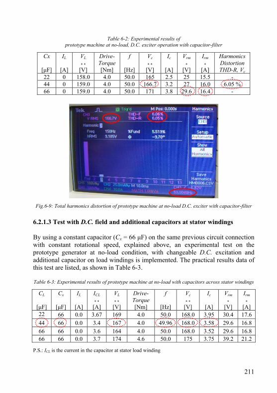
211
Table 6-2: Experimental results of prototype machine at no-load, D.C. exciter operation with capacitor-filter
Cx
[μF]
IL
[A]
VL
* * [V]
Drive- Torque [Nm]
f
[Hz]
Vc
* * [V]
Ic
[A]
Vrm
* [V]
Irm
* [A]
Harmonics Distortion THD-R, Vc
22 0 158.0 4.0 50.0 165 2.5 25 15.5 - 44 0 159.0 4.0 50.0 166.7 3.2 27 16.0 6.05 % 66 0 159.0 4.0 50.0 171 3.8 29.6 16.4 -
Fig.6-9: Total harmonics distortion of prototype machine at no-load D.C. exciter with capacitor-filter 6.2.1.3 Test with D.C. field and additional capacitors at stator windings By using a constant capacitor (Cx = 66 μF) on the same previous circuit connection with constant rotational speed, explained above, an experimental test on the prototype generator at no-load condition, with changeable D.C. excitation and additional capacitor on load windings is implemented. The practical results data of this test are listed, as shown in Table 6-3. Table 6-3: Experimental results of prototype machine at no-load with capacitors across stator windings
CL
[μF]
Cx
[μF]
IL
[A]
ICL
* * [A]
VL
* * [V]
Drive- Torque [Nm]
f
[Hz]
Vc
* * [V]
Ic
[A]
Vrm
* [V]
Irm
* [A]
22 66 0.0 3.67 169 4.0 50.0 168.0 3.95 30.4 17.6 44 66 0.0 3.4 167 4.0 49.96 168.0 3.58 29.6 16.8 66 66 0.0 3.6 164 4.0 50.0 168.0 3.52 29.6 16.8 66 66 0.0 3.7 174 4.6 50.0 175 3.75 39.2 21.2
P.S.: ICL is the current in the capacitor at stator load winding
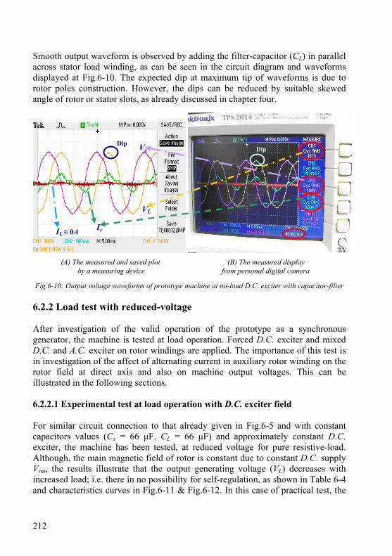
212
Smooth output waveform is observed by adding the filter-capacitor (CL) in parallel across stator load winding, as can be seen in the circuit diagram and waveforms displayed at Fig.6-10. The expected dip at maximum tip of waveforms is due to rotor poles construction. However, the dips can be reduced by suitable skewed angle of rotor or stator slots, as already discussed in chapter four.
(A) The measured and saved plot (B) The measured display by a measuring device from personal digital camera
Fig.6-10: Output voltage waveforms of prototype machine at no-load D.C. exciter with capacitor-filter
6.2.2 Load test with reduced-voltage After investigation of the valid operation of the prototype as a synchronous generator, the machine is tested at load operation. Forced D.C. exciter and mixed D.C. and A.C. exciter on rotor windings are applied. The importance of this test is in investigation of the affect of alternating current in auxiliary rotor winding on the rotor field at direct axis and also on machine output voltages. This can be illustrated in the following sections. 6.2.2.1 Experimental test at load operation with D.C. exciter field For similar circuit connection to that already given in Fig.6-5 and with constant capacitors values (Cx = 66 μF, CL = 66 μF) and approximately constant D.C. exciter, the machine has been tested, at reduced voltage for pure resistive-load. Although, the main magnetic field of rotor is constant due to constant D.C. supply Vrm, the results illustrate that the output generating voltage (VL) decreases with increased load; i.e. there in no possibility for self-regulation, as shown in Table 6-4 and characteristics curves in Fig.6-11 & Fig.6-12. In this case of practical test, the
Dip Dip
IL ≈ 0A
VL
Ic
Vc
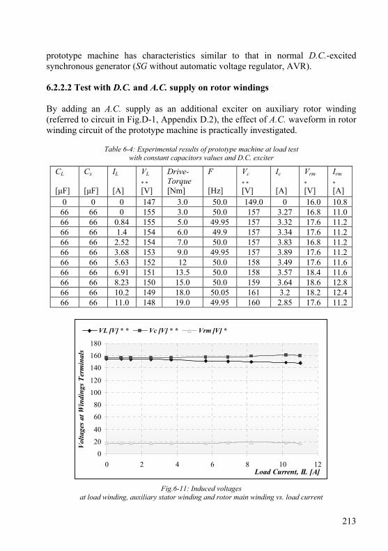
213
prototype machine has characteristics similar to that in normal D.C.-excited synchronous generator (SG without automatic voltage regulator, AVR). 6.2.2.2 Test with D.C. and A.C. supply on rotor windings By adding an A.C. supply as an additional exciter on auxiliary rotor winding (referred to circuit in Fig.D-1, Appendix D.2), the effect of A.C. waveform in rotor winding circuit of the prototype machine is practically investigated.
Table 6-4: Experimental results of prototype machine at load test with constant capacitors values and D.C. exciter
CL
[μF]
Cx [μF]
IL
[A]
VL
* * [V]
Drive- Torque [Nm]
F [Hz]
Vc
* * [V]
Ic
[A]
Vrm
* [V]
Irm
* [A]
0 0 0 147 3.0 50.0 149.0 0 16.0 10.8 66 66 0 155 3.0 50.0 157 3.27 16.8 11.0 66 66 0.84 155 5.0 49.95 157 3.32 17.6 11.2 66 66 1.4 154 6.0 49.9 157 3.34 17.6 11.2 66 66 2.52 154 7.0 50.0 157 3.83 16.8 11.2 66 66 3.68 153 9.0 49.95 157 3.89 17.6 11.2 66 66 5.63 152 12 50.0 158 3.49 17.6 11.6 66 66 6.91 151 13.5 50.0 158 3.57 18.4 11.6 66 66 8.23 150 15.0 50.0 159 3.64 18.6 12.8 66 66 10.2 149 18.0 50.05 161 3.2 18.2 12.4 66 66 11.0 148 19.0 49.95 160 2.85 17.6 11.2
0
20
40
60
80
100
120
140
160
180
0 2 4 6 8 10 12Load Current, IL [A]
Volta
ges a
t Win
ding
s Ter
min
als
VL [V] * * Vc [V] * * Vrm [V] *
Fig.6-11: Induced voltages at load winding, auxiliary stator winding and rotor main winding vs. load current
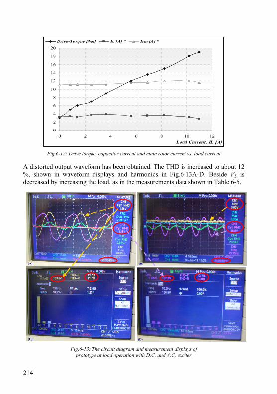
214
0
2
4
6
8
10
12
14
16
18
20
0 2 4 6 8 10 12Load Current, IL [A]
Drive-Torque [Nm] Ic [A] * Irm [A] *
Fig.6-12: Drive torque, capacitor current and main rotor current vs. load current A distorted output waveform has been obtained. The THD is increased to about 12 %, shown in waveform displays and harmonics in Fig.6-13A-D. Beside VL is decreased by increasing the load, as in the measurements data shown in Table 6-5.
Fig.6-13: The circuit diagram and measurement displays of prototype at load operation with D.C. and A.C. exciter
(A)
(C)
(B)
(D)
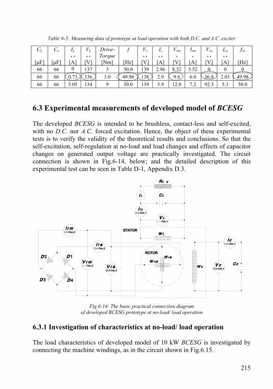
215
Table 6-5: Measuring data of prototype at load operation with both D.C. and A.C. exciter
CL
[μF]
Cx
[μF]
IL
* * [A]
VL
* * [V]
Drive- Torque [Nm]
f
[Hz]
Vc
* * [V]
Ic
* * [A]
Vrm
* [V]
Irm
* [A]
Vra
* * [V]
Ira
* * [A]
fra
[Hz]
66 66 0 137 3 50.0 139 2.96 8.32 5.52 0 0 0 66 66 0.73 136 3.0 49.96 138 2.9 9.6 6.0 36.8 2.03 49.98 66 66 5.05 134 9 50.0 139 3.9 12.0 7.2 92.3 5.3 50.0
6.3 Experimental measurements of developed model of BCESG The developed BCESG is intended to be brushless, contact-less and self-excited, with no D.C. nor A.C. forced excitation. Hence, the object of these experimental tests is to verify the validity of the theoretical results and conclusions. So that the self-excitation, self-regulation at no-load and load changes and effects of capacitor changes on generated output voltage are practically investigated. The circuit connection is shown in Fig.6-14, below; and the detailed description of this experimental test can be seen in Table D-1, Appendix D.3.
C x
STATOR
W r m
ROTOR
V cCh3-Osc.1
I cCh4-Osc.1
V LCh1-Osc.1
W c
W L
C L
R L
W r a
V r aCh3-Osc.2
I r aCh4-Osc.2
V r mCh1-Osc.2
I r mCh2-Osc.2
I t LCh2-Osc.1
I L
D 1D 2
D 3 D 4
Fig.6-14: The basic practical connection diagram of developed BCESG prototype at no-load/ load operation
6.3.1 Investigation of characteristics at no-load/ load operation The load characteristics of developed model of 10 kW BCESG is investigated by connecting the machine windings, as in the circuit shown in Fig.6.15.
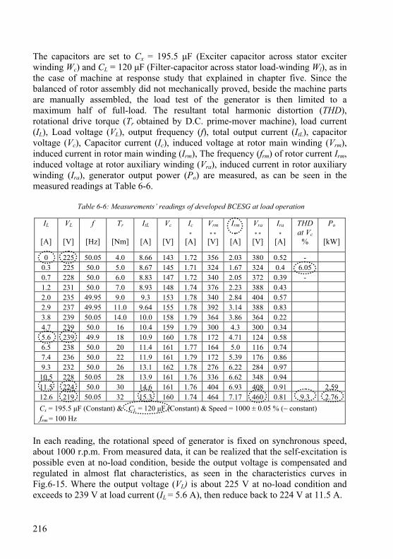
216
The capacitors are set to Cx = 195.5 μF (Exciter capacitor across stator exciter winding Wc) and CL = 120 μF (Filter-capacitor across stator load-winding Wl), as in the case of machine at response study that explained in chapter five. Since the balanced of rotor assembly did not mechanically proved, beside the machine parts are manually assembled, the load test of the generator is then limited to a maximum half of full-load. The resultant total harmonic distortion (THD), rotational drive torque (Tr obtained by D.C. prime-mover machine), load current (IL), Load voltage (VL), output frequency (f), total output current (ItL), capacitor voltage (Vc), Capacitor current (Ic), induced voltage at rotor main winding (Vrm), induced current in rotor main winding (Irm), The frequency (frm) of rotor current Irm, induced voltage at rotor auxiliary winding (Vra), induced current in rotor auxiliary winding (Ira), generator output power (Po) are measured, as can be seen in the measured readings at Table 6-6.
Table 6-6: Measurements’ readings of developed BCESG at load operation
In each reading, the rotational speed of generator is fixed on synchronous speed, about 1000 r.p.m. From measured data, it can be realized that the self-excitation is possible even at no-load condition, beside the output voltage is compensated and regulated in almost flat characteristics, as seen in the characteristics curves in Fig.6-15. Where the output voltage (VL) is about 225 V at no-load condition and exceeds to 239 V at load current (IL = 5.6 A), then reduce back to 224 V at 11.5 A.
IL
[A]
VL
[V]
f
[Hz]
Tr
[Nm]
ItL
[A]
Vc
[V]
Ic
* [A]
Vrm
* * [V]
Irm
* [A]
Vra
* * [V]
Ira
* [A]
THD at Vc
%
Po
[kW]
0 225 50.05 4.0 8.66 143 1.72 356 2.03 380 0.52 - 0.3 225 50.0 5.0 8.67 145 1.71 324 1.67 324 0.4 6.05 0.7 228 50.0 6.0 8.83 147 1.72 340 2.05 372 0.39 - 1.2 231 50.0 7.0 8.93 148 1.74 376 2.23 388 0.43 2.0 235 49.95 9.0 9.3 153 1.78 340 2.84 404 0.57 2.9 237 49.95 11.0 9.64 155 1.78 392 3.14 388 0.83 3.8 239 50.05 14.0 10.0 158 1.79 364 3.86 364 0.22 4.7 239 50.0 16 10.4 159 1.79 300 4.3 300 0.34 5.6 239 49.9 18 10.9 160 1.78 172 4.71 124 0.58 6.5 238 50.0 20 11.4 161 1.77 164 5.0 116 0.74 7.4 236 50.0 22 11.9 161 1.79 172 5.39 176 0.86 9.3 232 50.0 26 13.1 162 1.78 276 6.22 284 0.97
10.5 228 50.05 28 13.9 161 1.76 336 6.62 348 0.94 11.5 224 50.0 30 14.6 161 1.76 404 6.93 408 0.91 2.59 12.6 219 50.05 32 15.3 160 1.74 464 7.17 460 0.81 9.3 2.76
Cx = 195.5 μF (Constant) & CL = 120 μF (Constant) & Speed = 1000 ± 0.05 % (~ constant)
frm = 100 Hz

217
0
50
100
150
200
250
300
350
400
450
500
0 2 4 6 8 10 12 14Load Current IL (A)
Term
inal
Vol
tage
s at
Win
ding
s
VL [V] Vc [V] Vrm [V] * * Vra [V] * *
Fig.6-15: Induced terminal voltages of generator windings vs. load current, for developed BCESG model
It can also be found that the capacitor current (Ic) of stator capacitor-exciter winding is almost constant; because of constant capacitance value, while the field current (Irm) in the rotor main winding increases in proportional to the increase of load to substitute the lack of rotor field that occurs due to increase of armature reaction, as shown in Fig.6-16.
0
5
10
15
20
25
30
35
0 2 4 6 8 10 12 14
Load Current IL(A)
Tr [Nm] ItL [A] Ic [A] * Irm [A] * Ira [A] *
Fig.6-16: Torque and induced currents in the generator windings vs. load current, for developed BCESG model

218
In addition, the oscilloscope’s waveforms plots are recorded for the last reading, which shows that the load voltage waveform (CH1, at Fig.6-17A) is sinusoidal with 50 Hz frequency but with clear distortion near peak ends, shown in Fig.6-17A. Whereas the induced voltage at rotor main winding (CH1, at Fig.6-17B) is full-wave rectified with pulsating behave, referring to instants where the diode is actively energized. It can also be seen that voltage at rotor auxiliary winding is alternating in positive and negative pulses (CH3, Fig.6-17B), which refers to A.C. component in rotor circuit, already mentioned in response analysis, chapter five. The frequency at rotor circuit is shown 100 Hz; because the back-ward rotating field cutting the rotor windings and induces voltages of double frequency, already explained in analysis study, chapter three. The true power at this load is 2.76 kW and the reactive power due to the connected capacitor is 1.9 kVAR, while the resultant THD is little high about 9.28%, referred to practical results shown in displays of Fig.6-18 A & B, respectively.
(A) at stator windings (B) at rotor windings
Fig.6-17: Induced voltages, output frequency and currents for stator and rotor of developed BCESG model
(A) Output power (B) Harmonics distortion for output voltage
Fig.6-18: Output power and harmonics of output voltage of developed BCESG model
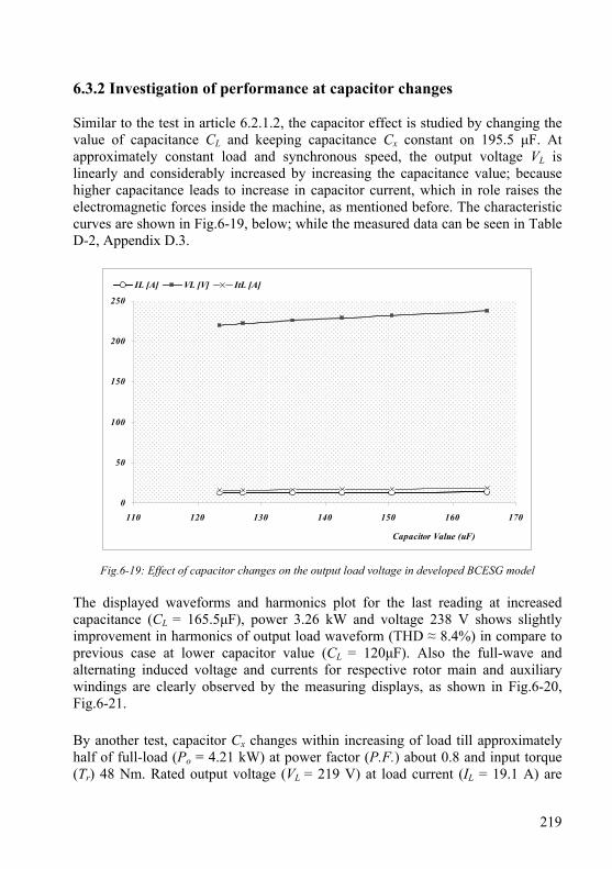
219
6.3.2 Investigation of performance at capacitor changes Similar to the test in article 6.2.1.2, the capacitor effect is studied by changing the value of capacitance CL and keeping capacitance Cx constant on 195.5 μF. At approximately constant load and synchronous speed, the output voltage VL is linearly and considerably increased by increasing the capacitance value; because higher capacitance leads to increase in capacitor current, which in role raises the electromagnetic forces inside the machine, as mentioned before. The characteristic curves are shown in Fig.6-19, below; while the measured data can be seen in Table D-2, Appendix D.3.
0
50
100
150
200
250
110 120 130 140 150 160 170
Capacitor Value (uF)
IL [A] VL [V] ItL [A]
Fig.6-19: Effect of capacitor changes on the output load voltage in developed BCESG model The displayed waveforms and harmonics plot for the last reading at increased capacitance (CL = 165.5μF), power 3.26 kW and voltage 238 V shows slightly improvement in harmonics of output load waveform (THD ≈ 8.4%) in compare to previous case at lower capacitor value (CL = 120μF). Also the full-wave and alternating induced voltage and currents for respective rotor main and auxiliary windings are clearly observed by the measuring displays, as shown in Fig.6-20, Fig.6-21. By another test, capacitor Cx changes within increasing of load till approximately half of full-load (Po = 4.21 kW) at power factor (P.F.) about 0.8 and input torque (Tr) 48 Nm. Rated output voltage (VL = 219 V) at load current (IL = 19.1 A) are
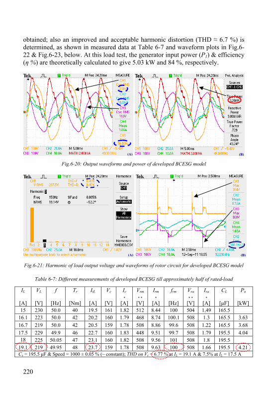
220
obtained; also an improved and acceptable harmonic distortion (THD ≈ 6.7 %) is determined, as shown in measured data at Table 6-7 and waveform plots in Fig.6-22 & Fig.6-23, below. At this load test, the generator input power (P1) & efficiency (η %) are theoretically calculated to give 5.03 kW and 84 %, respectively.
Fig.6-20: Output waveforms and power of developed BCESG model
Fig.6-21: Harmonic of load output voltage and waveforms of rotor circuit for developed BCESG model
Table 6-7: Different measurements of developed BCESG till approximately half of rated-load
IL
[A]
VL
[V]
f
[Hz]
Tr
[Nm]
ItL
[A]
Vc
[V]
Ic
* [A]
Vrm
* * [V]
Irm
* [A]
frm
[Hz]
Vra
* * [V]
Ira
* [A]
CL
[μF]
Po
[kW] 15 230 50.0 40 19.5 161 1.82 512 8.44 100 504 1.49 165.5
16.1 223 50.0 42 20.2 160 1.79 468 8.74 100.1 508 1.3 165.5 3.63 16.7 219 50.0 42 20.5 159 1.78 508 8.86 99.6 508 1.22 165.5 3.68 17.5 229 49.9 46 22.7 160 1.83 448 9.51 99.7 508 1.79 195.5 4.04 18 225 50.05 47 23.1 160 1.82 508 9.56 101 508 1.8 195.5
19.1 219 49.95 48 23.7 159 1.78 508 9.63 100 508 1.66 195.5 4.21 Cx = 195.5 μF & Speed = 1000 ± 0.05 % (~ constant); THD on Vc = 6.77 % at IL = 19.1 A & 7.5% at IL = 17.5 A
(B) (A)
(B) (A)

221
(A) Data of stator load- and exciter- windings (B) Data of rotor main and auxiliary windings
Fig.6-22: Induced voltages, output frequency and currents for stator and rotor of developed BCESG at half-load
(A) Output power (B) Harmonics distortion for output voltage
Fig.6-23: Output power and harmonics of output voltage of developed BCESG at half-load By referring again to harmonics plot in Fig.6-23B, it can easily be deduced that the higher percentage harmonics-distortion is presented mostly by the 3rd harmonics, which is expected in single-phase machines; because of elliptic revolving field. However, this can be reduced or eliminated in three-phase or two-phase balanced windings machines; because the armature revolving field becomes circular. Also, from displayed results for half-load operation of developed BCESG, shown in Fig.6-22A, the output load waveform with expected dips appears similar to the output waveform of the prototype already tested by forced D.C. exciter; although the BCESG is initially energized by a value of residual magnetism. This proves that in the presented brushless capacitor-exciter machine, a strong magnetic field, due to full-wave rectification may develop. Moreover, the maximum temperature at the machine frame at half-load after two
Di
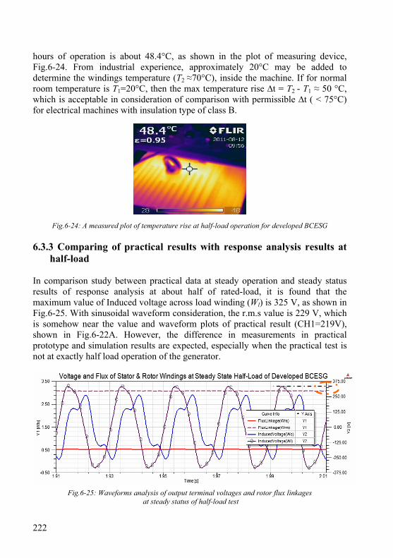
222
hours of operation is about 48.4°C, as shown in the plot of measuring device, Fig.6-24. From industrial experience, approximately 20°C may be added to determine the windings temperature (T2 ≈70°C), inside the machine. If for normal room temperature is T1=20°C, then the max temperature rise ∆t = T2 - T1 ≈ 50 °C, which is acceptable in consideration of comparison with permissible ∆t ( < 75°C) for electrical machines with insulation type of class B.
Fig.6-24: A measured plot of temperature rise at half-load operation for developed BCESG 6.3.3 Comparing of practical results with response analysis results at
half-load In comparison study between practical data at steady operation and steady status results of response analysis at about half of rated-load, it is found that the maximum value of Induced voltage across load winding (Wl) is 325 V, as shown in Fig.6-25. With sinusoidal waveform consideration, the r.m.s value is 229 V, which is somehow near the value and waveform plots of practical result (CH1=219V), shown in Fig.6-22A. However, the difference in measurements in practical prototype and simulation results are expected, especially when the practical test is not at exactly half load operation of the generator.
Fig.6-25: Waveforms analysis of output terminal voltages and rotor flux linkages at steady status of half-load test
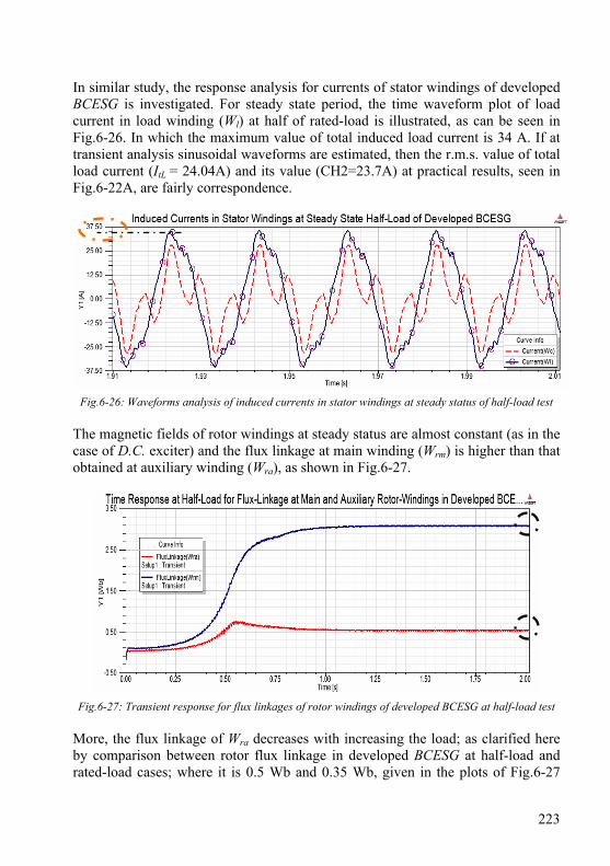
223
In similar study, the response analysis for currents of stator windings of developed BCESG is investigated. For steady state period, the time waveform plot of load current in load winding (Wl) at half of rated-load is illustrated, as can be seen in Fig.6-26. In which the maximum value of total induced load current is 34 A. If at transient analysis sinusoidal waveforms are estimated, then the r.m.s. value of total load current (ItL = 24.04A) and its value (CH2=23.7A) at practical results, seen in Fig.6-22A, are fairly correspondence.
Fig.6-26: Waveforms analysis of induced currents in stator windings at steady status of half-load test The magnetic fields of rotor windings at steady status are almost constant (as in the case of D.C. exciter) and the flux linkage at main winding (Wrm) is higher than that obtained at auxiliary winding (Wra), as shown in Fig.6-27.
Fig.6-27: Transient response for flux linkages of rotor windings of developed BCESG at half-load test More, the flux linkage of Wra decreases with increasing the load; as clarified here by comparison between rotor flux linkage in developed BCESG at half-load and rated-load cases; where it is 0.5 Wb and 0.35 Wb, given in the plots of Fig.6-27

224
and Fig.5-15, respectively. This is because of increasing of A.C. current component and related opposite directions auxiliary fields in the rotor auxiliary winding, as already explained in chapter three. Whence, the load voltage waveform is improved by increasing the generator load. 6.4 Experimental test of previous model of BCESG The load characteristic of previous model of BCESG is investigated by connecting each of rotor windings of prototype machine to a half-wave rectifier diode, as in the connection diagram shown in Fig.6.28. The capacitors are set to Cx = 195.5 μF and CL = 151.5 μF, higher than its value at developed BCESG. The number of windings and distribution for stator and rotor are set in similar manner to that for developed BCESG, shown in chapter four, Fig.4-18 and Fig.4-19, respectively. The load test took place till a limited value of load voltage about 200 V is obtained. Some of the measurements readings are recorded, as shown in Table 6-8, where the generator speed for every reading has been fixed on about 1000 r.p.m, synchronous speed.
C x
STATOR
W r m
ROTOR
V cCh3-Osc.1
I cCh4-Osc.1
V LCh1-Osc.1
W c
W L
C L
R L
W r a
V r aCh3-Osc.2
I r aCh4-Osc.2
V r mCh1-Osc.2
I r mCh2-Osc.2
I t LCh2-Osc.1
I L
D 1
D 2
Fig.6-28: The basic practical connection diagram of previous BCESG prototype at no-load/ load operation
From practical results, it can be realized that the self-excitation is also possible for previous BCESG, even though at no-load condition. Beside the output voltages
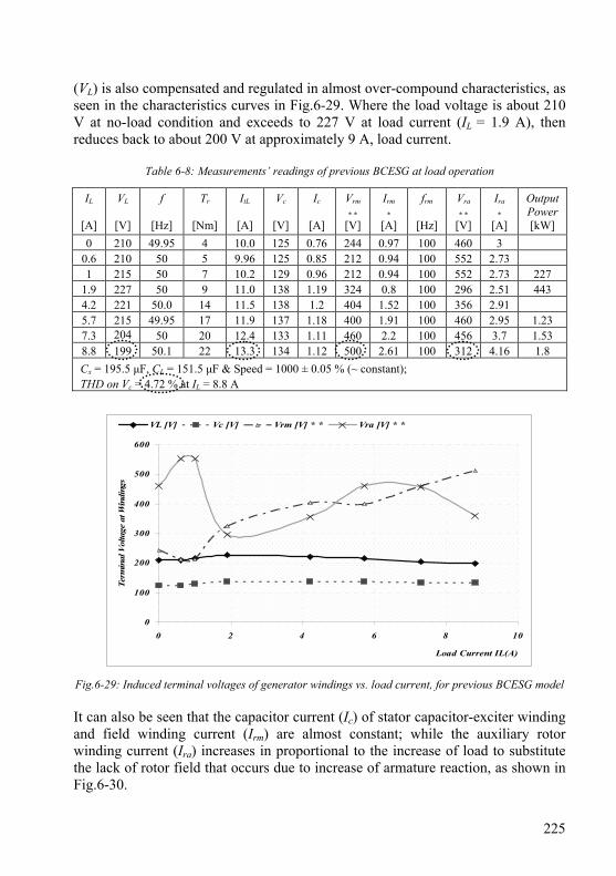
225
(VL) is also compensated and regulated in almost over-compound characteristics, as seen in the characteristics curves in Fig.6-29. Where the load voltage is about 210 V at no-load condition and exceeds to 227 V at load current (IL = 1.9 A), then reduces back to about 200 V at approximately 9 A, load current.
Table 6-8: Measurements’ readings of previous BCESG at load operation
IL
[A]
VL
[V]
f
[Hz]
Tr
[Nm]
ItL
[A]
Vc
[V]
Ic
[A]
Vrm
* * [V]
Irm
* [A]
frm
[Hz]
Vra
* * [V]
Ira
* [A]
Output Power [kW]
0 210 49.95 4 10.0 125 0.76 244 0.97 100 460 3 0.6 210 50 5 9.96 125 0.85 212 0.94 100 552 2.73 1 215 50 7 10.2 129 0.96 212 0.94 100 552 2.73 227
1.9 227 50 9 11.0 138 1.19 324 0.8 100 296 2.51 443 4.2 221 50.0 14 11.5 138 1.2 404 1.52 100 356 2.91 5.7 215 49.95 17 11.9 137 1.18 400 1.91 100 460 2.95 1.23 7.3 204 50 20 12.4 133 1.11 460 2.2 100 456 3.7 1.53 8.8 199 50.1 22 13.3 134 1.12 500 2.61 100 312 4.16 1.8
Cx = 195.5 μF, CL = 151.5 μF & Speed = 1000 ± 0.05 % (~ constant);
THD on Vc = 4.72 % at IL = 8.8 A
0
100
200
300
400
500
600
0 2 4 6 8 10
Load Current IL(A)
Term
inal
Vol
tage
at W
indi
ngs
VL [V] Vc [V] Vrm [V] * * Vra [V] * *
Fig.6-29: Induced terminal voltages of generator windings vs. load current, for previous BCESG model It can also be seen that the capacitor current (Ic) of stator capacitor-exciter winding and field winding current (Irm) are almost constant; while the auxiliary rotor winding current (Ira) increases in proportional to the increase of load to substitute the lack of rotor field that occurs due to increase of armature reaction, as shown in Fig.6-30.
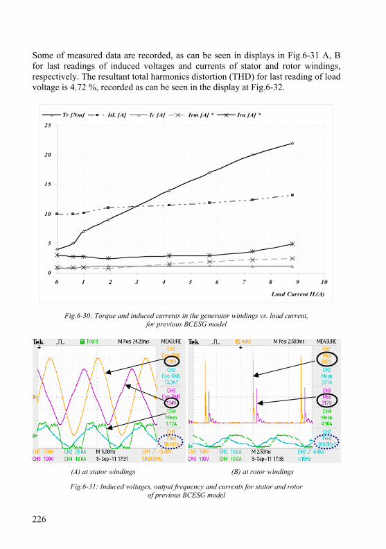
226
Some of measured data are recorded, as can be seen in displays in Fig.6-31 A, B for last readings of induced voltages and currents of stator and rotor windings, respectively. The resultant total harmonics distortion (THD) for last reading of load voltage is 4.72 %, recorded as can be seen in the display at Fig.6-32.
0
5
10
15
20
25
0 1 2 3 4 5 6 7 8 9 10
Load Current IL(A)
Tr [Nm] ItL [A] Ic [A] Irm [A] * Ira [A] *
Fig.6-30: Torque and induced currents in the generator windings vs. load current, for previous BCESG model
(A) at stator windings (B) at rotor windings
Fig.6-31: Induced voltages, output frequency and currents for stator and rotor of previous BCESG model
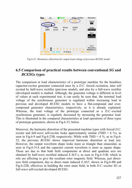
227
Fig.6-32: Harmonics distortion for output load voltage of previous BCESG model 6.5 Comparison of practical results between conventional SG and
BCESGs types The comparison at load characteristics of a prototype machine for the brushless capacitor-exciter generator connected once by a D.C. forced excitation, later self excited by half-wave rectifier (previous model), and also by a full-wave rectifier (developed model) is studied. Although, the generator voltage is different in level of values at each experimental test, it can easily be seen that, the terminal load voltage of the synchronous generator is regulated within increasing load in previous and developed BCESG models to have a flat-compound and over-compound generator characteristics, respectively, as it is already explained. Whereas, the load voltage of the prototype connected as a D.C.-excited synchronous generator, is regularly decreased by increasing the generator load. This is illustrated in the compared characteristics at load operations of three types of prototype generators, shown in Fig.6-33, below. Moreover, the harmonic distortion of the presented machine types with forced D.C. exciter and full-wave self-exciter looks approximately similar (THD ≈ 6 %), as seen in Fig.6-9 and Fig.6-23B, respectively; While with THD ≈ 4 %, as in Fig.6-32, the previous BCESG shows improved harmonic distortion at load test. However, the output waveform shape looks more as triangle than sinusoidal, as seen in Fig.6-31A and the capacitor current waveform is more as square shape. Those are due to that both field components at direct and quadrate axis are obtained by half-wave rectified induced E.M.F.s, as seen in Fig.6-31B; which in role are affecting to give the resultant rotor magnetic field. Whereas, just direct-axis field component, due to direct main induced E.M.F, shown in Fig.6-8B and Fig.6-22B, effectives in building the rotor main field, in both D.C.-exciter SG or full-wave self-excited developed BCESG.
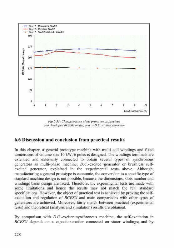
228
0
50
100
150
200
250
300
0 1 2 3 4 5 6 7 8 9 10
Load Current IL [A]
BC
ESG
Out
put V
olta
geVL [V] - Developed ModelVL [V] - Previous ModelVL [V] - Model with D.C. Exciter
Fig.6-33: Characteristics of the prototype as previous and developed BCESG model, and as D.C. excited generator
6.6 Discussion and conclusion from practical results In this chapter, a general prototype machine with multi coil windings and fixed dimensions of volume size 10 kW, 6 poles is designed. The windings terminals are extended and externally connected to obtain several types of synchronous generators as multi-phase machine, D.C.-excited generator or brushless self-excited generator, explained in the experimental tests above. Although, manufacturing a general prototype is economic, the conversion to a specific type of standard machine design is not possible, because the dimensions, slots number and windings basic design are fixed. Therefore, the experimental tests are made with some limitations and hence the results may not match the real standard specifications. However, the object of practical test is achieved by proving the self-excitation and regulation of BCESG and main comparisons with other types of generators are achieved. Moreover, fairly match between practical (experimental tests) and theoretical (analysis and simulation) results are obtained. By comparison with D.C.-exciter synchronous machine, the self-excitation in BCESG depends on a capacitor-exciter connected on stator windings; and by
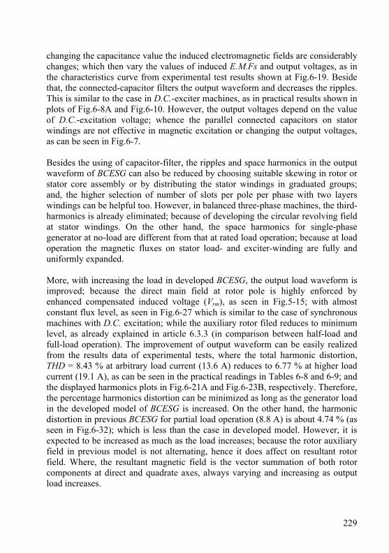
229
changing the capacitance value the induced electromagnetic fields are considerably changes; which then vary the values of induced E.M.Fs and output voltages, as in the characteristics curve from experimental test results shown at Fig.6-19. Beside that, the connected-capacitor filters the output waveform and decreases the ripples. This is similar to the case in D.C.-exciter machines, as in practical results shown in plots of Fig.6-8A and Fig.6-10. However, the output voltages depend on the value of D.C.-excitation voltage; whence the parallel connected capacitors on stator windings are not effective in magnetic excitation or changing the output voltages, as can be seen in Fig.6-7. Besides the using of capacitor-filter, the ripples and space harmonics in the output waveform of BCESG can also be reduced by choosing suitable skewing in rotor or stator core assembly or by distributing the stator windings in graduated groups; and, the higher selection of number of slots per pole per phase with two layers windings can be helpful too. However, in balanced three-phase machines, the third-harmonics is already eliminated; because of developing the circular revolving field at stator windings. On the other hand, the space harmonics for single-phase generator at no-load are different from that at rated load operation; because at load operation the magnetic fluxes on stator load- and exciter-winding are fully and uniformly expanded. More, with increasing the load in developed BCESG, the output load waveform is improved; because the direct main field at rotor pole is highly enforced by enhanced compensated induced voltage (Vrm), as seen in Fig.5-15; with almost constant flux level, as seen in Fig.6-27 which is similar to the case of synchronous machines with D.C. excitation; while the auxiliary rotor filed reduces to minimum level, as already explained in article 6.3.3 (in comparison between half-load and full-load operation). The improvement of output waveform can be easily realized from the results data of experimental tests, where the total harmonic distortion, THD = 8.43 % at arbitrary load current (13.6 A) reduces to 6.77 % at higher load current (19.1 A), as can be seen in the practical readings in Tables 6-8 and 6-9; and the displayed harmonics plots in Fig.6-21A and Fig.6-23B, respectively. Therefore, the percentage harmonics distortion can be minimized as long as the generator load in the developed model of BCESG is increased. On the other hand, the harmonic distortion in previous BCESG for partial load operation (8.8 A) is about 4.74 % (as seen in Fig.6-32); which is less than the case in developed model. However, it is expected to be increased as much as the load increases; because the rotor auxiliary field in previous model is not alternating, hence it does affect on resultant rotor field. Where, the resultant magnetic field is the vector summation of both rotor components at direct and quadrate axes, always varying and increasing as output load increases.
230
Moreover, the dip in the output waveform for the prototype generator at operation with D.C.-excitation is obtained due to the existence of non-salient slot in construction of the rotor salient poles that mentioned in chapter four. The waveform dips can also be partly extracted by choosing a suitable skewing angle for slots alignment in rotor or stator laminated packet. However, these dips can be reduced when self induced excitation is created. In this case, the electromagnetic fields in the machine construction are independently distributed in uniform arrangements at magnetic core, different than the case when the field is directed by a forced D.C. excitation. The reduction in dip level can easily be realized by comparing the displays of experimental tests results for brushless capacitor-exciter generator and D.C.-excited generator, shown in Fig.6-22A and Fig.6-10, respectively. Although, the dimensions and windings distribution for both BCESG models are similar, and also the induced currents in rotor windings are of double frequency; and more, the capacitor-exciter value for previous BCESG is higher (151.5 μF). The range of voltage regulation in developed prototype (between 224 V and 239 V) is higher than the regulation range in previous model (between 200 V and 227 V), as shown in experimental tests results of articles 6.3.1 and 6.4, respectively. Upon above, it is concluded that the induced excitation field in developed model is much stronger (with full-wave rectified excitation) than in previous model (with half-wave rectified rotor excitation). This corresponds to theoretical results of response analysis study at rated-load, already illustrated in the plots of Fig.5-15 and Fig.5-16, chapter five.
231
Chapter 7
Wind/ Hydro Fluctuation Solver (LPEC)
The objective of this chapter is to prove that the developed BCESG is easily controlled [1]. A simple low-power electronic circuit (LPEC) is built. It is basically constructed of operational amplifier (as comparator) and externally connected between load and capacitor stator winding. The function of this LPEC is to assist in continuous generation of BCESG machine at extended levels of rotational speed, higher or lower than the rated. Though, it is helpful in wind and hydro generating systems to solve the problem of fluctuations in speed at a wider limit. For same purpose, it can also be used in diesel generating systems. The electronic control circuit is built by an aid of MULTISIM electronic-components software. In the following sections, the description of the LPEC design, operation and performance are presented. 7.1 Description and design of the integrated control circuit As can be seen from schematic diagram at Fig.7-1, the LPEC is mainly designed by combining of two comparators. The output voltage (Vl) of the generator feeds the electronic circuit in two separate paths; one is the variable voltage (Channel_A), which is proportional to generator output load-voltage. The other path is ended by a fixed reference voltage (Channel_B). The output of first comparator feeds one terminal input of the second comparator. Where the both comparators-outputs (Channel_C and Channel_D) are of logical values. The values logic“0” or logic“1” apply on transistor-switches (shown in electronic circuit at Fig.D-4, Appendix D.5), which in roll submit control signals I1 and I2 on contactor-coils T1 and T2, through suitable relays. The contacts of the contactors are combined in connecting with more of two capacitors C1 and C2, as shown in the blocks of the mentioned Fig.7-1. The capacitors combination are connected in parallel to the terminals of the capacitor-exciter winding (Wc) of the generator. The combination circuit is designed to have three capacitances values. Each value for each status of generator operation is self inserted. The status are at over, under and normal rotational speed. The LPEC also comprises sub-circuits to reduce, rectify, filter, alter and divide the incoming A.C. rated load voltage.
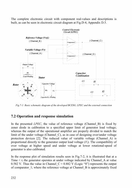
232
The complete electronic circuit with component real-values and descriptions is built, as can be seen in electronic circuit diagram at Fig.D-4, Appendix D.5.
Variable Voltage (Vr)
Comparator1
Reference Voltage (Vref.)
Comparator2
( Channel_B )
( Channel_A ) ( Channel_D )
( Channel_C )-
+
+
-
Control ElectronicCircuit (LPEC)
C2
C1
CapacitorCombination
Vl
Load-Winding
Output Voltage
Wc
Wl
CapacitorEx.-Winding
Capacitor Voltage
+-Wrm
Rotor
Stator
Wra
D1D2
D3 D4
Vc
I1
I2
Fig.7-1: Basic schematic diagram of the developed BCESG, LPEC and the external connection 7.2 Operation and response simulation In the presented LPEC, the value of reference voltage (Channel_B) is fixed by zener diode in calibration to a specified upper limit of generator load voltage; whereas the output of the operational amplifier are properly divided to match the limit of the under voltage (Channel_C), as in case of designing over/under voltage protection devices [2]. The reduced value of variable voltage (Channel_A) is proportional directly to the generator output load voltage (Vl). The compatibility of over voltage at higher speed and under voltage at lower rotational-speed of generator is also calibrated. In the response plot of simulation results seen in Fig.7-2, it is illustrated that at a Time < t1 the generator operates at under voltage indicated by Channel_A at value 0.582 V. Thus the value in Channel_C ≈ 0.882 V (Logic “0”) represents the output of comparator_1; where the reference voltage at Channel_B is approximately fixed

233
on 2.4 V. In the mean time, the output of comparator_2 is then represented by Logic “1” ( ≈ 2.7 V), obtained at Channel_D. Since the transistors are of npn type, then the control signals are I1 ≈ 0 V and I2 ≈ 12 V apply onto contactors to switch contactor_2 at ON mode; while the mode of contactor_1 is kept unchanged (OFF), as shown in Fig.7-1. At this case of under voltage at lower speed operation of the generator, the contact K1T1 of contactor T1 remains unchanged at normally-closed status. While, the normally-opened contact (K1T2) and normally closed contact (K2T2) of contactor T2 are altered. Hence, the high capacitance value (C2) in the capacitors combination circuit is inserted. This leads to higher capacitor current (Ic) in the stator winding Wc at zero power factor; and hence the overall amount of electromagnetic field inside the machine is increased by self-compensation of induced terminal voltages.
Fig.7-2: Simulation layout of the output response of LPEC at normal rotational speed test of the generator
The same procedure is applied when the machine rotates at normal speed level. Whence in the normal limits of load voltage, represented by the response at Time ≥ t1, Fig.7-1; the value of voltage in Channel_A is gradually increased, in
Channel_D, Logic“1”
Channel_B
Channel_C, Logic“0”
Channel_A
Channel_D, Logic“0” Channel_C, Logic“0” &
Time = t1
234
proportion to the increment of generated load voltage. As long as this value is below the reference voltage (at Channel_B), the output of comparator_1 (Channel_C) is set to minimum (logic “0”). In the mean time, the output of comparator_2 also alters to logic “0”; because at normal rotational speed the value of voltage at Channel_A becomes higher than that at Channel_C, as represented in the simulation plot at Fig.7-2. The new instruction signals I1 ≈ 12 V and I2 ≈ 12 V are applied in the capacitor combination circuit. Thus the contactors (T1 and T2) are both activated, and the normal statuses of related contacts are changed. Therefore, the capacitor of lower value (C1) can now be set in parallel with Wc winding; which leads in decrement of capacitor current (Ic). In proportional to that, the terminal induced voltages are reduced back to normal values at normal speed operation. For the same purpose and in same manner, at over-limit generator operation an equivalent value of parallel capacitors (C1//C2) can be inserted. It is considerable here to mention that in each setting case of new operation level of generation, a feed-back signal is submitted to change the limits of reference voltage at Channel_B and the divided voltage at Channel_C, by using means of additional simple arrangements. Though, the output combinations of comparators remain unchangeable after regulating the generator voltage at new level of rotational speed and rated load range. The additional circuit arrangements are well illustrated in the schematic diagram of complete electronic circuit of LPEC, seen at Fig.D-4, Appendix D. 7.3 Discussion of generating system with LPEC device The results shown in the response of electronic control circuit imply that the self-regulation at limited changes in rotational speed of developed BCESG is possible. Although, the output frequency can not be regulated; the output voltage of the generator is self-adjusted for three levels of operation, as given in over and under limits of normal rotational speed level. Beside, the generator is also self-regulated at each level for limited changes in output load. Moreover in LPEC low-power electronic components are used. The mechanical contactors can also be replaced by electronic types. For this purpose, power-electronic components may then be inserted; however, it would be then of limited use. Therefore, the generating system with LPEC is more economic from systems with power electronic converters or regulators. Finally, the combination of two capacitors to give three values of capacitance can automatically be selected and the capacitors regulation method is more efficient than other methods; because no active-power loss is provided. Beside, the capacitors absorb the reactive power when connected to the network.
235
Chapter 8
General Conclusions and Future Outlook
In this research work, a developed design model of brushless synchronous generating system of wound rotor type is presented. This system is related to grid integration and the need of replacing the high prices unsustainable sources with renewable energy power sources. The generator type is self-excited and self-regulated and can be also compensated for considerable changes of load or limited levels of rational speed. Therefore, it can be applicable for wind/ hydro energy plants as well as diesel engines units. The presented generator can also solve the problem of fluctuation at sudden changes of power because of it is exclusive damping features embedded in rotor construction without using damper windings. Although, the electromagnetic field is based on induction principle, the presented brushless generator has a steady strong magnetic field similar to the case in D.C. exciter field of conventional synchronous generator types. Therefore, it is highly recommended for power system stability when it is connected to a grid. The brushless generating system is completed by a simple external electronic circuit (mainly based on operational amplifier as a comparator), which is fed by output voltage. The control circuit provides instruction signals in proportion to the changes of load voltage due to rotational speed variations, in upper and lowers limits from rated speed. According to that, suitable value of capacitance at a capacitor combination circuit is organized. Thus, the electromagnetic forces change in proportion to the new capacitor current and the system is re-compensated for the new rotational speed level. In the following, the main features, conclusions, discussion and future works are well illustrated. 8.1 Descriptions and final conclusions of the presented research
project The research project is concentrated on developing a BCESG system and the following has been achieved:
- An overview at back ground of the problem in relating to fluctuations, power stability and cost of wind turbine generator systems.
- Comprehensive study of the state of art and the difference in construction and characteristics between existent and presented types of brushless synchronous generators.
236
- A new concept and development in designing and performance of brushless self-excited and self-regulated capacitor excited synchronous generators.
- Illustration of analysis and design procedure for the presented brushless synchronous generator; besides to manufacturing of a general prototype 10 kW, 6 poles machine.
- Theoretical and experimental investigation to the induced self-excitation and self-regulation of the presented machine by using finite elements analysis and laboratory tests. Besides displaying the measured waveforms plots for harmonics, waveforms of induced voltages, currents and power in the rotor and stator winding circuits of the machine.
- A presentation and study of comparison results between simulation and animation process of electromagnetic models. Also the displays of magnetic and electrical field distributions and waveforms at steady and transient response analysis in relating to previous half-wave rectified exciter type of BCESG.
- Response study and discussion of analytical results for the presented machine in compare to conventional types of D.C.-exciter salient and non-salient poles generators.
Upon the comprehensive study and results of the presented developed generating system, the following has been concluded; and more theoretically and practically approved:
1 - Although the magnetic forces are produced by induced currents starting from initial residual magnetism, the rotor main magnetic field is built up and enforced stable at steady state operations; because it includes the full-wave and half-wave rectified components. The self-excitation is developed and raised by interacting between armature current and auxiliary rotor winding in proportional to increase of output load. Therefore, the magnetic characteristics can be similar to that in a synchronous generator of permanent-magnetic or D.C.-exciter salient poles machines.
2- The output characteristic may have flat compound compensating
characteristics. Also, the residual magnetism and generated voltage is maintained, even after sudden short circuit circumstances or operation at inverse directions of rotational speed. Where the flux linkages are enhanced and increased higher at increasing the load up to short circuit condition; which is positively adopted for stable operation.
3 - The resultant alternating and opposing magnetic fields at quadrant-axis
(high reluctance part of rotor) are reduced to minimum value near zero. Hence, the
237
harmonics of the output waveform is improved. Also, for suitable saturation, the core material can be reduced at pole parts. This is considerable from economic viewpoint in comparison to standard size of induction or synchronous machines.
4 - The auxiliary winding in rotor auxiliary slots (at non-salient part of pole)
carries the A.C. component of rotor currents and has short circuit paths. Though, beside the voltage compensation, the function of these windings is to damp the torsional oscillations in the rotor that may occur as a result of load fluctuations. Therefore, this plays a role in preventing rotor overheating when a synchronous machine is exposed to negative sequence currents in a subject of short-circuit case or machine hunting’s, as in the case of damper windings.
5 - The developed BCESG can show self-compound characteristics when it
is operated at rated speed and connected to a changeable load for limit changes. This self compensated can be obtained without additional control circuits, D.C. or rotating A.C. exciters or external D.C. exciter means. Beside, the capacitor-exciter approach, used here, reduces the power loss in compare to the variable resistors or inductors control methods.
6- Above all, the operating concept including self excitation and regulation
is applicable and the construction is simple and robust; because it is contact-less (without brushes, slip-rings nor commentators are used). The design procedure may successfully apply for double poles, as well as multi poles machines.
7- Because of the reduction in resultant auxiliary rotor field with increased
loads, the flux leakages and harmonics at rated load is found, in comparison, less than that of other types of synchronous machines.
8- Increasing capacitor value or changing the windings numbers of stator
excitation winding or load winding plays roll in changing the self-excitation and building up the output voltage of developed BCESG. This is due the increase in circuit output gain near the resonance tuning frequencies. 8.2 Advanced concepts and future work
- Since the revolving field in 3 phase generator is circular and not ellipse or pulsating, then the back-ward field in the machine is zero, especially when the machine is working in balanced operation. Hence for 3-phase BCESG machine, the compensation may occur just at unbalanced load. On the other hand, a concept to get unbalanced or non-circular revolving field for self-compensation is that to connect the output voltage terminals with un-equal values of parallel capacitances,
238
to obtain unbalance revolving fields and back-ward field components; and then the self-regulation may succeed. This way is better than to apply three unbalanced load on the machine. However, the terminals voltage per phase for the three-phases may not be equal between phases.
- Limited site study to investigate the power stability by using three-phase large scale BCESG in integrated grid with renewable energies.
- The self-regulation in output frequency beside the generated voltage compensation for developed BCESG at speed and/ or load changes. However, with the devised control device (LPEC) the output frequency can not be regulated through speed changes.
- The contactors can in further work be replaced by electronic switch to eliminate the mechanical parts and reduce any undesirable electrical lose. The power electronics components may then be required; however, this use will be in expected economic limits.
239
Appendices
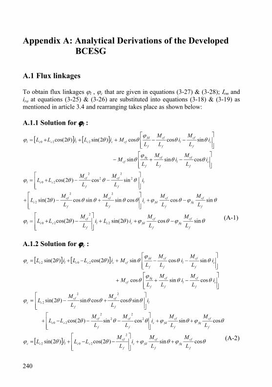
240
Appendix A: Analytical Derivations of the Developed BCESG
A.1 Flux linkages To obtain flux linkages ϕl , ϕc that are given in equations (3-27) & (3-28); Ιrm and ira at equations (3-25) & (3-26) are substituted into equations (3-18) & (3-19) as mentioned in article 3.4 and rearranging takes place as shown below: A.1.1 Solution for ϕl :
[ ] [ ]
⎥⎥⎦
⎤
⎢⎢⎣
⎡−+−
⎥⎥⎦
⎤
⎢⎢⎣
⎡−−+++=
cf
cfl
f
cf
f
fqcf
cf
cfl
f
cf
f
fdcfcclccl
iL
Mi
LM
LM
iL
Mi
LM
LMiLiLL
θθϕ
θ
θθϕ
θθθϕ
cossinsin
sincoscos)2sin()2cos( 220
θϕθϕθθθθθ
θθθϕ
sincoscossinsincos)2sin(
sincos)2cos(
22
2
22
22
20
f
cffq
f
cffdc
f
cf
f
cfc
lf
cf
f
cfccl
LM
LM
iL
ML
ML
iL
ML
MLL
−+⎥⎥⎦
⎤
⎢⎢⎣
⎡+−+
⎥⎥⎦
⎤
⎢⎢⎣
⎡−−+=
θϕθϕθθϕ sincos)2sin()2cos( 2
2
20f
cffq
f
cffdccl
f
cfccl L
ML
MiLi
LM
LL −++⎥⎥⎦
⎤
⎢⎢⎣
⎡−+= (A-1)
A.1.2 Solution for ϕc :
[ ] [ ]
⎥⎥⎦
⎤
⎢⎢⎣
⎡−++
⎥⎥⎦
⎤
⎢⎢⎣
⎡−−+−+=
cf
cfl
f
cf
f
fqcf
cf
cfl
f
cf
f
fdcfccclcc
iL
Mi
LM
LM
iL
Mi
LM
LMiLLiL
θθϕ
θ
θθϕ
θθθϕ
cossincos
sincossin)2cos()2sin( 202
θϕθϕθθθ
θθθθθϕ
cossincossin)2cos(
sincoscossin)2sin(
22
22
20
22
2
f
cffq
f
cffdc
f
cf
f
cfcc
lf
cf
f
cfcc
LM
LM
iL
ML
MLL
iL
ML
ML
++⎥⎥⎦
⎤
⎢⎢⎣
⎡−−−+
⎥⎥⎦
⎤
⎢⎢⎣
⎡+−=
[ ] θϕθϕθθϕ cossin)2cos()2sin(2
202f
cffq
f
cffdc
f
cfcclcc L
ML
Mi
LM
LLiL ++⎥⎥⎦
⎤
⎢⎢⎣
⎡−−+= (A-2)

241
A.2 Determination of current components Ic1 , Ic3 and Ιc5 By substituting equations (3-6) for θ and (3-33) for ic into equation (3-34), the following derivations are applied,
[ ][ ]
[ ] 0)5cos()3cos()cos(1
)cos()sin(
)5cos()3cos()cos()22cos(
553311
55331120
=++++++
⎪⎭
⎪⎬
⎫
⎪⎩
⎪⎨
⎧
++++
++++++−′
∫ dttItItIC
LtM
LtM
tItItItLL
dtd
cccccc
f
fqcf
f
fdcf
cccccccc
ϑωϑωϑω
ϕδω
ϕδω
ϑωϑωϑωδω
0)cos()cos(
)5sin(5
1)3sin(3
1)sin(1)22sin()5cos(2)5sin()22cos(5)22sin()3cos(2)3sin()22cos(3
)22sin()cos(2)sin()22cos()5sin(5)3sin(3)sin(
553311
552552
332332
112112
550330110
=++++
++++++
++++++++++++
+++++++′−+′−+′−
f
fqcf
f
fdcf
cccccc
cccccc
cccccc
cccccc
ccccccccc
LtM
dtdt
LM
tIC
tIC
tIC
ttILttILttILttIL
ttILttILtILtILtIL
ϕδωδω
ϕω
ϑωω
ϑωω
ϑωω
δωϑωωϑωδωωδωϑωωϑωδωω
δωϑωωϑωδωωϑωωϑωωϑωω
As illustrated in article 3.4 and formula (3-22), the term of resultant opposite directions flux linkage fqϕ is neglected relatively to the permanent flux
linkage fdϕ , hence:
0)cos()5sin(5
1)3sin(3
1)sin(1
)22sin()5cos(2)5sin()22cos(5)22sin()3cos(2)3sin()22cos(3
)22sin()cos(2)sin()22cos()5sin(5)3sin(3)sin(
553311
552552
332332
112112
550330110
=++++++++
++++++++++++
+++++++′−+′−+′−
δωϕ
ωϑωω
ϑωω
ϑωω
δωϑωωϑωδωωδωϑωωϑωδωω
δωϑωωϑωδωωϑωωϑωωϑωω
tL
MtIC
tIC
tIC
ttILttILttILttIL
ttILttILtILtILtIL
f
fdcfcccccc
cccccc
cccccc
cccccc
ccccccccc
⎪⎪⎪⎪⎪⎪⎪
⎭
⎪⎪⎪⎪⎪⎪⎪
⎬
⎫
=++++++++
+−−++++−+
++++−−+++
+−++++−++
+++−+−+++
+′−+′−+′−
0)cos()5sin(5
)3sin(3
)sin(
)23sin()27sin()23sin(25
)27sin(25)2sin()25sin(
)2sin(23)25sin(
23)2sin(
)23sin()2sin(21)23sin(
21
)5sin(5)3sin(3)sin(
553311
552552552
552332332
332332112
11212112
550330110
δωϕ
ϑωϑωϑω
ϑδωϑδωϑδω
ϑδωϑδωϑδω
ϑδωϑδωϑδω
ϑδωϑδωϑδω
ϑωϑωϑω
tL
XtIX
tIX
tIX
tIXtIXtIX
tIXtIXtIX
tIXtIXtIX
tIXtIXtIX
tIXtIXtIX
f
fdcfcc
Ccc
CccC
ccccccccc
ccccccccc
ccccccccc
ccccclcccc
ccccccccc
(A-3)
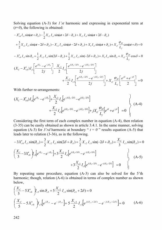
242
Solving equation (A-3) for 1’st harmonic and expressing in exponential term at (t=0), the following is obtained:
0)cos()sin()2sin()2sin(23
)2sin()2sin(21)sin(
11332332
112112110
=+++++−−+−+
−++−+−+′−
δωϕ
ϑωϑδωϑδω
ϑδωϑδωϑω
tL
XtIXtIXtIX
tIXtIXtIX
f
fdcfccCcccccc
ccccccccc
0cossin)2sin(21)2sin(
21sin 11332112110 =+++−+−+′− δ
ϕϑϑδϑδϑ
f
fdcfccCccccccccc L
XIXIXIXIX
0222
222)(
)2()2(
32
)2()2(
12
10
33
1111
=⎥⎦
⎤⎢⎣
⎡ ++⎥
⎦
⎤⎢⎣
⎡ −+
⎥⎦
⎤⎢⎣
⎡ −−⎥
⎦
⎤⎢⎣
⎡ −′−
−−−−
−−−−
δδδϑδϑ
δϑδϑϑϑ
ϕ jj
f
fdcf
jj
cc
jj
cc
jj
ccC
eeL
XjeeIX
jeeI
XjeeIXX
cc
cccc
With further re-arrangements:
[ ] [ ]
[ ] [ ]⎪⎪⎭
⎪⎪⎬
⎫
=++−+
−+−′−
−−−−
−−−−
02
2)(
)2()2(3
2
)2()2(1
210
33
1111
δδδϑδϑ
δϑδϑϑϑ
ϕ jj
f
fdcf
jjc
c
jjc
cjjccC
eeL
jXeeIX
eeIXeeIXX
cc
cccc
(A-4)
Considering the first term of each complex number in equation (A-4), then relation (3-35) can be easily obtained as shown in article 3.4.1. In the same manner, solving equation (A-3) for 3’rd harmonic at boundary “ t = 0 ” results equation (A-5) that leads later to relation (3-36), as in the following.
0)sin(3
)2sin(23)2sin(
23)sin(3 33552112330 =++−+++′− cc
Cccccccccc IXIXIXIX ϑϑδϑδϑ
[ ] [ ]
[ ] ⎪⎪⎭
⎪⎪⎬
⎫
=−+
−+−⎟⎠⎞
⎜⎝⎛ ′−
−−−
+−+−
02
3
233
3)2()2(
52
)2()2(1
230
55
1133
δϑδϑ
δϑδϑϑϑ
cc
cccc
jjc
c
jjc
cjjcc
C
eeIX
eeIXeeIXX (A-5)
By repeating same procedure, equation (A-3) can also be solved for the 5’th harmonic; though, relation (A-6) is obtained in terms of complex number as shown below,
0)2sin(2
5sin55 33
2550 =++⎟
⎠⎞
⎜⎝⎛ ′− δϑϑ cc
cccc
C IXIXX
[ ] [ ] 02
555
)2()2(3
250
3355 =−+−⎟⎠⎞
⎜⎝⎛ ′− +−+− δϑδϑϑϑ cccc jj
ccjj
ccC eeIXeeIXX (A-6)
243
A.3 Determination of ⎟⎠⎞
⎜⎝⎛
rmIdtd at boundary condition
Since at no-load Ail 0.0= ”, then equation (3-25) may present again as the following,
ccffdrmf iMIL θϕ sin−=
By derivation of both sides, the following relation is obtained
( ) ( )ccffdrmf iMdtd
dtdIL
dtd θϕ sin−=−
But the term ⎟⎠⎞
⎜⎝⎛ − fddt
d ϕ is equal to zero according to equation (3-23); hence, the
above relation can be expressed now, by referring to the boundary condition at equation (3-51), as follows:
( ) ( )00
sin==
−=t
ccft
rmf iMdtdIL
dtd θ ; or: ( ) 0
00 ==
==
trmftd IL
dtdemf (A-7)
Since the self-inductance is considered higher than resistance, relation (A-7) is represented as,
( ) 00
==t
rmf IdtdL (A-8)
By dividing both sides of equation (A-8) over Lf , the boundary condition for the rectified field current (Irm) yields as given in equation (3-54) at article (3.5.2). A.4 Determinant equation of δ A.4.1 First derivation As illustrated in article 3.5.2, the arrangements are took place from equation (3-58), as the following:
0)2
55cos()2
33cos()2
cos()sin(0
531 =⎭⎬⎫
⎩⎨⎧
⎥⎦⎤
⎢⎣⎡ −+++++−++
=tccccf tItItItM
dtd πδωπδωπδωδω
By substituting equations (3-48) and (3-49) into the above equation and continuing the derivation with assumption that Mcf is constant , the following is obtained:
[ ] 0)55sin()33sin()sin()sin(0
3531 =+++−++=t
ccf tKKtKttIMdtd δωδωδωδω
0)66sin(3)44sin(2
)44sin(2)22sin()22sin(
03535
33 =+++−
+−+++
=ttKKtKK
tKtKtδωδω
δωδωδω (A-9)
244
From equation (A-9) and after substituting for “ t = 0 ”, the determinant equation of ” δ “ can easily be deduced as shown in equation (3-59) of article 3.5.2. A.4.2 Second derivation In similar manner, from equation (3-61) in article 3.5.2, the second derivation is:
[ ] 0)55sin()33sin()sin()sin(0
5312
2
>+++−++−=t
ccccf tItItItMdtd δωδωδωδω
Substituting equations (3-48) & (3-49) into above relation and solving in terms of fundamental,
0)55sin()sin()33sin()sin(
)sin()sin(
035312
2
>⎭⎬⎫
⎩⎨⎧
⎥⎦
⎤⎢⎣
⎡+++++−
++−
=t
ccf ttKKttKtt
IMdtd
δωδωδωδωδωδω
Dividing both sides over “2ω“ and ”Mcf “ yields:
( ) ( )0
)66cos(18)44cos(8)22cos(12
053
53331 >⎥
⎦
⎤⎢⎣
⎡++
++−++−
=t
c tKKtKKKtK
Iδωω
δωωδωω (A-10)
By substituting “ t=0 ” in the above relation and dividing over “ 2ω ”, relation (3-62) in article 3.5.2 is achieved.
A.5 Determination of ⎟⎠⎞
⎜⎝⎛
fddd ϕδ
and ⎟⎟⎠
⎞⎜⎜⎝
⎛fdd
d ϕδ 2
2
Since the same initial condition in article 3.5.2 is considered, hence the flux linkage that expressed in equation (3-58) is substituted here; and the following mathematical derivations is obtained,
[ ] )5sin(sin)3sin(sinsin 5332
1 δδδδδϕδ
KKKIMdtd
dd
ccffd +−=
( )[ ] [ ] ( )[ ] ⎭⎬⎫
⎩⎨⎧
−+−−−= )6cos(4cos)4cos(2cos2cos12 5331 δδδδδ
δϕ
δKKKI
Mdd
dd
ccf
fd
( ) ( ) ( ) ( )[ ])6sin(34sin22sin1 5353331 δδδϕδ
KKKKKKIMdd
ccffd ++−+= (A-11)
The right side of equation (A-11) is similar to result in equation (3-59) (before the division over “ 1ccf IM ”); hence, it is realized ⎟
⎠⎞
⎜⎝⎛ = 0fdd
d ϕδ
as in equation (3-63).
By applying second-order’s derivation on equation (A-11), the relation (3-64) from the following rearranging can easily be obtained as:
( ) ( ) ( ) ( )[ ] )6sin(34sin22sin1 53533312
2
δδδδ
ϕδ
KKKKKKIMdd
dd
ccffd ++−+=

245
Dividing both sides over “ -1 ” yields:
( ) ( ) ( ) ( )[ ])6cos(94cos42cos12 53533312
2
δδδϕδ
KKKKKKIMdd
ccffd ++−+−=− (A-12)
Which looks similar to the result at relation (3-62) before division over the term
“ cfM2 ”. Hence:⎟⎟⎠
⎞⎜⎜⎝
⎛>− 02
2
fddd ϕδ
; or: ⎟⎟⎠
⎞⎜⎜⎝
⎛< 02
2
fddd ϕδ
, as given in equation (3-64).
A.6 The solution to obtain the value of “ δ ” From equation (3-59), the solution is determined in terms of “ 2δ “ as the following,
( ) ( ) 0)42sin(3)2cos()2sin(4)2sin(1 535333 =+++−+ δδδδδ KKKKKK
( ) ( )[ ] 0)2sin()2(cos6)2(sin)2(cos)2sin(3
)2cos()2sin(4)2sin(12
5322
53
5333
=+−+
+−+
δδδδδ
δδδ
KKKK
KKKK
( ) ( )[ ] 031)2cos(4)2(cos12)2sin( 5335332
53 =−+++− KKKKKKKK δδδ (A-13)
From equation (A-13), two solutions may valid. These are given in equations (3-65) and (3-66) at article 3.5.2. A.7 Values of capacitor reactance and generation modes A.7.1 The condition at capacitor reactance XC5
From the relation (3-75), the following is valid:0251
cLC
′< ωω
; or, 0
2
251
cLC
′>ω
Hence:CLc 05
1′
>ω (A-15)
If the term in the right hand side of relation (A-15) satisfies the resonance frequency. Hence, the angular frequency at 5th harmonics waveform (ω) in the capacitor resonant circuit of the generator is assumed greater than that of resonance frequency. Then the capacitor-excitation circuit is assumed inductive at the 5th harmonics waveform as already mentioned in article 3.5.4 . A.7.2 The condition at capacitor reactance XC3 The value of the capacitor at 3rd harmonic current is considered first for simplicity at “ K5 = 0 ”, though the general approximate solution of equation (3-76) is:
023 cC XX ′= (A-16)
246
To modify the solution, the above value is substituted again in equation (3-76) after replacing K5 by the formula of equation (3-40). Then, the solution of capacitor reactance value for the 3rd harmonics (XC3) could be given as shown below.
⎥⎥⎥⎥⎥
⎦
⎤
⎢⎢⎢⎢⎢
⎣
⎡
⎟⎟⎠
⎞⎜⎜⎝
⎛′−
′
⎟⎠⎞
⎜⎝⎛
+′=
020
2
22
02
3
53
23
cc
c
cC
XX
X
XX (A-17)
By rearranging the above relation, equation (3-77) for modified solution of capacitance reactance at 3rd harmonics is achieved as presented in article 3.5.4. A.7.3 The condition at fundamental capacitor reactance XC Substituting K3=0 equation (3-78) satisfy the fundamental condition and yields:
⎥⎦⎤
⎢⎣⎡ +′=
22
0c
cCXXX (A-18)
The assumption ( 5CC XX << ) from equation (3-74) refers to 025 cC XX ′<< or,
025 cC XX ′<< (A-19)
By applying the condition at (A-19) into equation (3-40), the following is obtained:
0
25 2 c
c
XXK
′−= (A-20)
Substituting equation (A-20) into equation (3-44) yields the following,
⎪⎭
⎪⎬⎫
⎪⎩
⎪⎨⎧
⎥⎥⎦
⎤
⎢⎢⎣
⎡⎟⎟⎠
⎞⎜⎜⎝
⎛′
−′−⎟⎠
⎞⎜⎝
⎛=0
2202
23 2232 c
ccc
Cc
XXX
XXX
K (A-21)
From equation (A-18), the term for XC is substituted in equation (A-21) to give:
⎥⎥⎦
⎤
⎢⎢⎣
⎡′−
′+⎟
⎠
⎞⎜⎝
⎛ +′⎟⎠
⎞⎜⎝
⎛= 00
222
02
3 4291
2 cc
ccc
c XX
XXX
XK
Finally, by substituting the above new expression for K3 into equation (3-78), the approximate solution for the first root of fundamental value of capacitor reactance (XC1) is obtained, as shown below.
⎥⎥⎥⎥
⎦
⎤
⎢⎢⎢⎢
⎣
⎡
′−′
+⎟⎠⎞
⎜⎝⎛ +′
⎟⎠⎞
⎜⎝⎛
++′=
00
222
0
2
201
4291
212
cc
ccc
c
ccC
XX
XXX
XXXX
(A-22)
Equation (A-22) is considered for further rearranging as given in article 3.5.4.

247
A.8 Induced generator voltage el0 As mentioned in article 3.5.5.1, by substituting equations (3-82), (3-83) and (3-6) into equation (3-81), expanding and deriving in terms of time changes “ t ”, the expression for the generator induced EMF on winding Wrm at no-load operation is obtained from the derivation shown below:
( ) ( )
⎪⎪⎪
⎭
⎪⎪⎪
⎬
⎫
⎪⎪⎪
⎩
⎪⎪⎪
⎨
⎧
+⎥⎦⎤
⎢⎣⎡ +−′−+
⎥⎥⎥⎥⎥⎥⎥
⎦
⎤
⎢⎢⎢⎢⎢⎢⎢
⎣
⎡
−++
+++
−+
+−= δωω
πδω
πδω
πδω
δω tKLLX
tKK
tK
t
tLIdtde c
cC
ccl cos12
)2
55cos(
)2
33cos(
)2
cos(
)22sin( 32
0
35
3210
[ ][ ]
( ) ( )⎪⎭
⎪⎬
⎫
⎪⎩
⎪⎨
⎧+⎥⎦
⎤⎢⎣⎡ +−′−−
⎥⎥⎥
⎦
⎤
⎢⎢⎢
⎣
⎡
+−+−+−++
+++−= δω
ωδωδω
δωδωδωδω
tKLLX
ttKKttK
ttLI
dtde c
cCc
cl cos12
)77cos()33cos()55cos()cos(
)33cos()cos(
2 32
0
35
32
10
( ) ( )⎪⎭
⎪⎬
⎫
⎪⎩
⎪⎨
⎧
+⎥⎦⎤
⎢⎣⎡ +−′−+
⎥⎥⎥
⎦
⎤
⎢⎢⎢
⎣
⎡
+−+++−−
+−= δω
δωδωδω
δωtXKXX
tKKtKtKK
tKXIe c
cCc
cl sin2
1)77sin(7)55sin(5
)33sin()1(3)sin()1(
22
30
353
35
32
10
[ ] ( )
⎪⎪⎭
⎪⎪⎬
⎫
⎪⎪⎩
⎪⎪⎨
⎧
+⎟⎠⎞
⎜⎝⎛−+⎟
⎠⎞
⎜⎝⎛+
+−⎟⎠⎞
⎜⎝⎛−+−′−
=)77sin(
27)55sin(
25
)33sin()1(2
3sin
352
32
352
320
10
δωδω
δωδω
tKKXtKX
tKKXtKXXXIe
cc
cccC
cl
(A-23)
After some further arrangements on equation (A-23), the final formula for induced voltage el0 can be show in equation (3-84) at article 3.5.5.1. A.9 Induced capacitor voltage ec0 As it is mentioned in article 3.5.2 and from equation (3-87), the rearranging in terms of fundamental capacitor current component takes place as the following:
dttIKKtIKtIC
e cccc ∫ ⎥⎦⎤
⎢⎣⎡ −+++++−+= )
255cos()
233cos()
2cos(1
1351310πδωπδωπδω
[ ]dttIKKtIKtIC
e cccc ∫ +++−+= )55sin()33sin()sin(11351310 δωδωδω
⎥⎦⎤
⎢⎣⎡ +−+++−= )55cos(
51)33cos(
31)cos(1
1351310 δωδωδωω
tIKKtIKtIC
e cccc (A-24)
The terms in the above formula are expressed in equation (3-88) at article 3.5.5.2.
248
A.10 Determination of rotor currents From equation (3-91) in article 3.5.5.4, the rearranging is shown below to obtain effective main field current Irm.
⎥⎥⎥
⎦
⎤
⎢⎢⎢
⎣
⎡
+++−+−++++−
−++−−=
)66cos()44cos()44cos()22cos()22cos(1)6cos()4cos()4cos()2cos()2cos(1
23535
33
535333
1
δωδωδωδωδωδδδδδ
tKKtKKtKtKt
KKKKKKI
LM
I cf
cfrm
( ) ( )( ) ( ) ⎥
⎦
⎤⎢⎣
⎡++++−+++
−+++−=
)66cos()44cos()22cos(1)6cos()4cos()2cos(1
2 355333
5353331 δωδωδω
δδδtKKtKKKtK
KKKKKKI
LM
I cf
cfrm
(A-25)
The rearranging of equation (A-25) yields equation (3-92) in Article 3.5.5.4. A.11 Voltage and current relations A.11.1 Load circuit As explained already in article 3.6.1, substituting equations (3-27) and (3-96) into equation (3-31) and rearranging take place as the following.
[ ] [ ] 0)cos(sincos)2sin()2cos( 11220 =++⎪⎭
⎪⎬⎫
⎪⎩
⎪⎨⎧
−+++′ llf
fqcf
f
fdcfcclcc tIR
LM
LMiLiLL
dtd ϑω
ϕθ
ϕθθθ
In above relation, substituting instead of θ , ic and il [from equations (3-6), (3-97) and (3-96)] yields:
0)cos(
)sin()cos()2sin(21
)23sin(21)23cos(
21
)2cos(21)cos(
11
112
112121
121110
=++
⎪⎪⎪
⎭
⎪⎪⎪
⎬
⎫
⎪⎪⎪
⎩
⎪⎪⎪
⎨
⎧
+−++−++
++++++
−+++′
ll
f
fqcf
f
fdcfccc
ccclcl
lclllc
tIR
LtM
LtMtIL
tILtLI
tLItIL
dtd ϑω
ϕδω
ϕδωϑδω
ϑδωϑδω
ϑδωϑω
By solving for only fundamental wave component, the relation is reduced to:
0)cos()sin()cos(
)2sin(21)2cos(
21)cos(
11
112112110
=++
⎪⎪⎭
⎪⎪⎬
⎫
⎪⎪⎩
⎪⎪⎨
⎧
+−++
−++−+++′
ll
f
fqcf
f
fdcf
cccllcllc
tIR
LtM
LtM
tILtILtIL
dtd ϑωϕ
δωϕ
δω
ϑδωϑδωϑω
Derivation in term of time and rearrangement takes place as following,
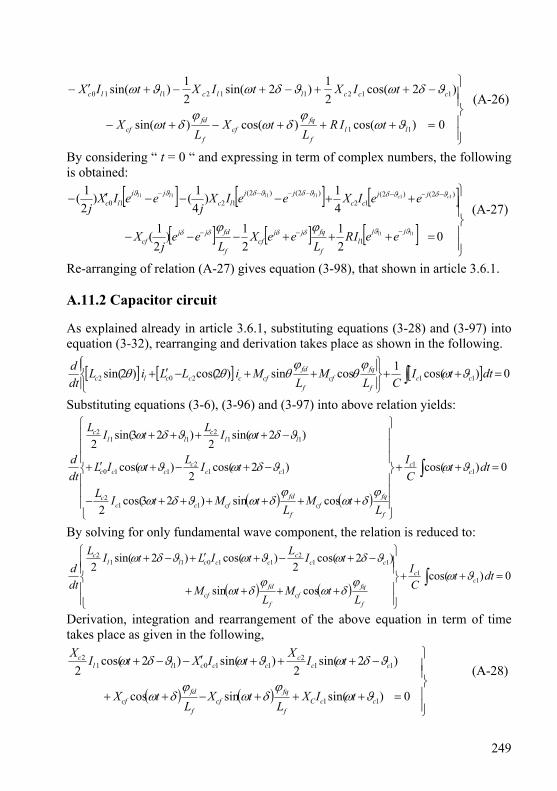
249
⎪⎪⎭
⎪⎪⎬
⎫
=+++−+−
−++−+−+′−
0)cos()cos()sin(
)2cos(21)2sin(
21)sin(
11
112112110
llf
fqcf
f
fdcf
cccllcllc
tIRL
tXL
tX
tIXtIXtIX
ϑωϕ
δωϕ
δω
ϑδωϑδωϑω (A-26)
By considering “ t = 0 “ and expressing in term of complex numbers, the following is obtained:
[ ] [ ] [ ]
[ ] [ ] [ ]⎪⎪⎭
⎪⎪⎬
⎫
=+++−−−
++−−−′−
−−−
−−−−−−−
021
21)
21(
41)
41()
21(
11
111111
1
)2()2(12
)2()2(1210
ll
ccllll
jjl
f
fqjjcf
f
fdjjcf
jjcc
jjlc
jjlc
eeIRL
eeXL
eej
X
eeIXeeIXj
eeIXj
ϑϑδδδδ
ϑδϑδϑδϑδϑϑ
ϕϕ (A-27)
Re-arranging of relation (A-27) gives equation (3-98), that shown in article 3.6.1. A.11.2 Capacitor circuit As explained already in article 3.6.1, substituting equations (3-28) and (3-97) into equation (3-32), rearranging and derivation takes place as shown in the following.
[ ] [ ] [ ] 0)cos(1cossin)2cos()2sin( 11202 =++⎪⎭
⎪⎬⎫
⎪⎩
⎪⎨⎧
++−′+ ∫ dttICL
ML
MiLLiLdtd
ccf
fqcf
f
fdcfccclc ϑω
ϕθ
ϕθθθ
Substituting equations (3-6), (3-96) and (3-97) into above relation yields:
( ) ( )
0)cos(
cossin)23cos(2
)2cos(2
)cos(
)2sin(2
)23sin(2
11
112
112
110
112
112
=++
⎪⎪⎪
⎭
⎪⎪⎪
⎬
⎫
⎪⎪⎪
⎩
⎪⎪⎪
⎨
⎧
++++++−
−+−+′+
−++++
∫ dttCI
LtM
LtMtIL
tILtIL
tILtIL
dtd
cc
f
fqcf
f
fdcfcc
c
ccc
ccc
llc
llc
ϑω
ϕδω
ϕδωϑδω
ϑδωϑω
ϑδωϑδω
By solving for only fundamental wave component, the relation is reduced to:
( ) ( )0)cos(
cossin
)2cos(2
)cos()2sin(2
11
112
110112
=++
⎪⎪⎭
⎪⎪⎬
⎫
⎪⎪⎩
⎪⎪⎨
⎧
++++
−+−+′+−+
∫ dttCI
LtM
LtM
tILtILtIL
dtd
cc
f
fqcf
f
fdcf
ccc
cccllc
ϑωϕδω
ϕδω
ϑδωϑωϑδω
Derivation, integration and rearrangement of the above equation in term of time takes place as given in the following,
( ) ( )⎪⎪⎭
⎪⎪⎬
⎫
=+++−++
−+++′−−+
0)sin(sincos
)2sin(2
)sin()2cos(2
11
112
110112
ccCf
fqcf
f
fdcf
ccc
cccllc
tIXL
tXL
tX
tIXtIXtIX
ϑωϕ
δωϕ
δω
ϑδωϑωϑδω (A-28)
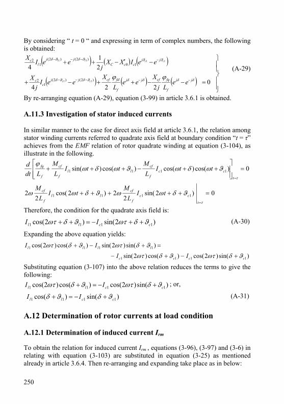
250
By considering “ t = 0 “ and expressing in term of complex numbers, the following is obtained:
( ) ( ) ( )
( ) ( ) ( )⎪⎪⎭
⎪⎪⎬
⎫
=−−++−+
−′−++
−−−−−
−−−−
0224
21
4
)2()2(1
2
10)2()2(
12
11
1111
δδδδϑδϑδ
ϑϑϑδϑδ
ϕϕ jj
f
fqcfjj
f
fdcfjjc
c
jjccC
jjl
c
eeLj
Xee
LX
eeIj
X
eeIXXj
eeIX
cc
ccll
(A-29)
By re-arranging equation (A-29), equation (3-99) in article 3.6.1 is obtained. A.11.3 Investigation of stator induced currents In similar manner to the case for direct axis field at article 3.6.1, the relation among stator winding currents referred to quadrate axis field at boundary condition “t = τ” achieves from the EMF relation of rotor quadrate winding at equation (3-104), as illustrate in the following.
0)cos()cos()cos()sin( 1111 =⎥⎥⎦
⎤
⎢⎢⎣
⎡++−+++
=τ
ϑωδωϑωδωϕ
t
ccf
cfll
f
cf
f
fq ttIL
MttI
LM
Ldtd
0)2sin(2
2)2cos(2
2 1111 =+++++=τ
ϑδωωϑδωωt
ccf
cfll
f
cf tIL
MtI
LM
Therefore, the condition for the quadrate axis field is:
)2sin()2cos( 1111 ccll II ϑδωτϑδωτ ++−=++ (A-30)
Expanding the above equation yields:
)sin()2cos()cos()2sin(
)sin()2sin()cos()2cos(
1111
1111
cccc
llll
II
II
ϑδωτϑδωτ
ϑδωτϑδωτ
+−+−
=+−+
Substituting equation (3-107) into the above relation reduces the terms to give the following:
)sin()2cos()cos()2cos( 1111 ccll II ϑδωτϑδωτ +−=+ ; or,
)sin()cos( 1111 ccll II ϑδϑδ +−=+ (A-31) A.12 Determination of rotor currents at load condition A.12.1 Determination of induced current Irm To obtain the relation for induced current Irm , equations (3-96), (3-97) and (3-6) in relating with equation (3-103) are substituted in equation (3-25) as mentioned already in article 3.6.4. Then re-arranging and expanding take place as in below:
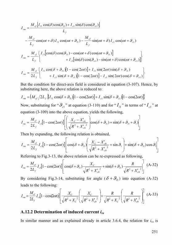
251
[ ]
)cos()sin()cos()cos(
)cos()sin()cos()cos(
1111
1111
ccf
cfll
f
cf
f
ccllcfrm
tItL
MtIt
LM
LIIM
I
ϑωδωϑωδω
ϑδϑδ
++−++−
+=
[ ][ ]⎭
⎬⎫
⎩⎨⎧
++−+
++−=
)cos()sin()cos()sin(
)cos()cos()cos()cos(
111
111
ccc
lll
f
cfrm ttI
ttIL
MI
ϑωδωϑδ
ϑωδωϑδ
[ ][ ] ⎭
⎬⎫
⎩⎨⎧
+−−++
++−+=
)cos()2sin()2cos(1)sin(
)sin()2sin()2cos(1)cos(2 1111
1111
cccc
llll
f
cfrm tItI
tItIL
MI
ϑδωωϑδ
ϑδωωϑδ
But the condition for direct-axis field is considered in equation (3-107). Hence, by substituting here, the above relation is reduced to:
( ) [ ] [ ] )2cos(1)sin()2cos(1)cos(2 1111 tItILMI ccllfcfrm ωϑδωϑδ −++−+=
Now, substituting for “ 1cϑ ” at equation (3-110) and for “ 1lI ” in terms of “ 1cI ” at equation (3-109) into the above equation, yields the following,
[ ]⎥⎥
⎦
⎤
⎢⎢
⎣
⎡++++⎟
⎟
⎠
⎞
⎜⎜
⎝
⎛
′+
′−−= )sin()cos()2cos(1
2 11120
2
01 ϑϑδϑδω ll
c
cCc
f
cfrm
XR
XXtIL
MI
Then by expanding, the following relation is obtained,
[ ]⎥⎥
⎦
⎤
⎢⎢
⎣
⎡++⎟
⎟
⎠
⎞
⎜⎜
⎝
⎛+
′+
′−+−= 1112
02
011 cos)sin(sin)cos()2cos(1
2ϑϑδϑϑδω l
c
cClc
f
cfrm
XR
XXtIL
MI
Referring to Fig.3-13, the above relation can be re-expressed as following,
[ ]⎥⎥⎦
⎤
⎢⎢⎣
⎡
′+++
′++−=
20
2120
211 )sin()cos()2cos(12
c
l
c
Clc
f
cfrm
XR
R
XR
XtIL
MI ϑδϑδω (A-32)
By considering Fig.3-14, substituting for angle ( 1lϑδ + ) into equation (A-32) leads to the following:
[ ]⎥⎥
⎦
⎤
⎢⎢
⎣
⎡
⎟⎟
⎠
⎞
⎜⎜
⎝
⎛
′+++⎟
⎟
⎠
⎞
⎜⎜
⎝
⎛
′++−=
20
22220
2221 )2cos(12
cCc
C
C
Cc
f
cfrm
XR
R
XR
R
XR
X
XR
XtIL
MI ω (A-33)
A.12.2 Determination of induced current ira In similar manner and as explained already in article 3.6.4, the relation for ira is

252
obtained by substituting the same equations (3-96), (3-97) and (3-6) in relating with equation (3-105) into equation (3-26). Then re-arranging and expanding take place as shown below:
⎥⎥⎦
⎤
⎢⎢⎣
⎡
++−+++
+++++−=
)cos()cos()cos()sin(
)cos()cos()cos()sin(
1111
1111
ccll
ccll
f
cfra ttIttI
II
LM
iϑωδωϑωδω
ϑωτδωτϑωτδωτ
[ ][ ]⎭
⎬⎫
⎩⎨⎧
+++−+−++
+−+−+++=
)sin()2sin()cos()2cos()sin()2sin()cos()2cos(
)sin()2cos()cos()2sin()sin()2cos()cos()2sin(2 11111
11111
ccccc
lllll
f
cfra ttI
ttIL
Mi
ϑδωϑδωϑδωτϑδωτ
ϑδωτϑδωτϑδωϑδω
Rearranging gives:
[ ] [ ][ ] [ ]⎭
⎬⎫
⎩⎨⎧
−++−++
−++−+=
)2sin()2sin()sin()2cos()2cos()cos(
)2cos()2cos()sin()2sin()2sin()cos(2 1111
1111
ωτωϑδωωτϑδ
ωτωϑδωτωϑδ
tItI
tItIL
Mi
cccc
llll
f
cfra
Substituting equation (3-107) into the above relation gives:
[ ] [ ] )2sin()2sin()sin()2sin()2sin()cos(2 1111 ωτωϑδωτωϑδ −++−+= tItI
LM
i ccllf
cfra
Substituting equation (3-110) and (3-109) into the above equation, expanding and rearranging yields:
[ ]⎥⎥
⎦
⎤
⎢⎢
⎣
⎡+++⎟
⎟
⎠
⎞
⎜⎜
⎝
⎛+
′+
′−−= 11112
02
01 cos)sin()cos(sin)2sin()2sin(
2ϑϑδϑδϑωτω ll
c
cCc
f
cfra
XR
XXItL
Mi
By referring again to Fig.s (3-11) and (3-12), the equivalence of trigonometric functions in the above equations with respect to angles ( 1ϑ ) and ( 1lϑδ + ) can be substituted as given below:
[ ]⎥⎥
⎦
⎤
⎢⎢
⎣
⎡
′+⎟⎟
⎠
⎞
⎜⎜
⎝
⎛
++
+⎟⎟
⎠
⎞
⎜⎜
⎝
⎛
′+−=
20
2222220
21)2sin()2sin(2
cCC
C
c
Cc
f
cfra
XR
R
XR
R
XR
X
XR
XItL
Mi ωτω (A-34)
A.13 Power factor and load angle The term “ϑl1 - δ ” is determined here from load circuit and it is investigated again referring to the capacitor circuit as illustrated below: A.13.1 Determination of angle “ ϑl1 - δ ” referring to load circuit By considering equation (3-63), the term “ δϑ −1l ” is determined; where the derivation of the direct field flux in terms of angle “ δ ” is zero as a condition

253
explained before in chapter three. Hence by dividing both sides of equation (3-98) over the exponential function “ δje ”, substituting for the angle “ 1cϑ ” and “ 1lI ” and rearranging, the following is obtained:
fdf
cffq
f
cfjc
cjc
c
cCcjc
c
cCc L
Xj
LX
eIXeIXR
XXXjeIXR
XXXjR lll ϕϕδϑϑδϑδϑ −=+′+
′−+
′+
′−′+ −+−−−− )(1
2)(12
02
02)(12
02
00
1111
22)(
Expressing in terms of trigonometric function gives:
[ ] [ ]
[ ] fdf
cffq
f
cfllc
c
llc
c
cCcllc
c
cCc
LX
jLX
jIX
jIXR
XXXjjIXR
XXXjR
ϕϕδϑϑδϑϑ
δϑδϑδϑδϑ
−=−+−−++
−−−′+
′−+−+−
′+
′−′+
)sin()cos(2
)sin()cos(2
)sin()cos()(
111112
11120
2
021112
02
00
By expanding and further re-arranging, the following is obtained:
fdf
cffq
f
cfc
lc
lc
l
c
cCcl
c
cCc
l
c
cCcl
c
cCc
l
c
cCl
c
cC
LX
jLX
I
XjXXR
XXX
XR
XXXj
XR
XXXXR
XXXj
XR
XXjRXR
XXR
ϕϕ
δϑϑδϑϑ
δϑδϑ
δϑδϑ
δϑδϑ
−=
⎥⎥⎥⎥⎥⎥⎥⎥⎥⎥⎥
⎦
⎤
⎢⎢⎢⎢⎢⎢⎢⎢⎢⎢⎢
⎣
⎡
−+−−++
−′+
′−⎟⎠⎞
⎜⎝⎛+−
′+
′−⎟⎠⎞
⎜⎝⎛+
−′+
′−′−−′+
′−′+
−′+
′−+−
′+
′−
1
112
112
120
2
0212
02
02
120
2
0012
02
00
120
2
012
02
0
)sin(2
)cos(2
)sin(2
)cos(2
)sin()cos(
)sin()cos(
To solve for direct axis field, the imaginary terms are taken into consideration as shown below:
fdf
cfc
lc
l
c
cCc
l
c
cCcl
c
cC
LX
IX
XR
XXXXR
XXXXR
XXR
ϕδϑϑδϑ
δϑδϑ
−=
⎥⎥⎥⎥⎥
⎦
⎤
⎢⎢⎢⎢⎢
⎣
⎡
−+−−′+
′−+
−′+
′−′+−′+
′−
1
112
120
2
02
120
2
0012
02
0
)sin(2
)cos(2
)cos()sin(
By applying the condition at equation (3-63), as mentioned above, the following is obtained:
0)sin()sin(2
)cos()cos(2
)sin(2
)sin()cos(
112
112
120
2
02
120
2
0012
02
0
=−+−−−′+
′−−
−′+
′−′−−′+
′−
δϑϑδϑϑδϑ
δϑδϑ
lc
lc
l
c
cCc
l
c
cCcl
c
cC
XX
XR
XXXXR
XXXXR
XXR
Considering Fig.3-13 and substituting instead of trigonometric functions ϑ1 gives:
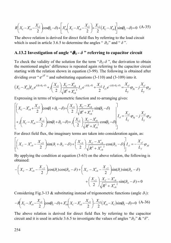
254
( ) 0)sin(22
)cos(2 10
22001
20 =−⎥
⎦
⎤⎢⎣
⎡ ′−+⎟⎠⎞
⎜⎝⎛ −′−′+−⎟
⎠⎞
⎜⎝⎛ −′− δϑδϑ lcC
cccCcl
ccC XXXXXXXXXXR (A-35)
The above relation is derived for direct field flux by referring to the load circuit which is used in article 3.6.5 to determine the angles “ ϑl1” and “ δ ”. A.13.2 Investigation of angle “ϑl1 - δ ” referring to capacitor circuit To check the validity of the solution for the term “ϑl1-δ ”, the derivation to obtain the mentioned angles’ difference is repeated again referring to the capacitor circuit starting with the relation shown in equation (3-99). The following is obtained after dividing over “ δje ” and substituting equations (3-110) and (3-109) into it.
( ) fdf
cffq
f
cfjc
cjc
c
cCcjccC L
Xj
LX
eIXeIXR
XXXjeIXX lll ϕϕδϑϑδϑδϑϑ −=+′+
′−⎟⎠⎞
⎜⎝⎛+′− −+−−−−+ )(
12)(
120
2
02)(10
11111
22
Expressing in terms of trigonometric function and re-arranging gives:
fdf
cffq
f
cfc
l
c
cCcl
ccC
l
c
cCcl
ccC
LX
jLX
I
XR
XXXjXXXj
XR
XXXXXX
ϕϕδϑδϑϑ
δϑδϑϑ
−=
⎥⎥⎥⎥⎥
⎦
⎤
⎢⎢⎢⎢⎢
⎣
⎡
−′+
′−⎟⎠⎞
⎜⎝⎛+−+⎟
⎠⎞
⎜⎝⎛ −′−+
−′+
′−⎟⎠⎞
⎜⎝⎛+−+⎟
⎠⎞
⎜⎝⎛ +′−
1
120
2
0211
20
120
2
0211
20
)cos(2
)sin(2
)sin(2
)cos(2
For direct field flux, the imaginary terms are taken into consideration again, as:
fdf
cfcl
c
cCcl
ccC L
XI
XR
XXXXXX ϕδϑδϑϑ −=⎥⎥⎦
⎤
⎢⎢⎣
⎡−
′+
′−⎟⎠⎞
⎜⎝⎛+−+⎟
⎠⎞
⎜⎝⎛ −′− 112
02
0211
20 )cos(
2)sin(
2
By applying the condition at equation (3-63) on the above relation, the following is obtained:
0)sin(2
)sin()sin(2
)cos()cos(2
120
2
02
112
0112
0
=−′+
′−⎟⎠⎞
⎜⎝⎛+
−⎟⎠⎞
⎜⎝⎛ −′−+−⎟
⎠⎞
⎜⎝⎛ −′−−
δϑ
δϑϑδϑϑ
l
c
cCc
lc
cClc
cC
XR
XXX
XXXXXX
Considering Fig.3-13 & substituting instead of trigonometric functions (angle ϑ1):
( ) 0)sin(22
)cos(2 10
22001
20 =−−′−⎟
⎠⎞
⎜⎝⎛ −′−′+−⎟
⎠⎞
⎜⎝⎛ −′−− δϑδϑ lCc
cccCcl
ccC XXXXXXXXXXR (A-36)
The above relation is derived for direct field flux by referring to the capacitor circuit and it is used in article 3.6.5 to investigate the values of angles “ϑl1” & “δ”.
255
A.14 Determination of rotor field fluxes at load condition From article 3.6.6 the main and auxiliary rotor fields at load condition can be determined, as follows. A.14.1 Determination of “φfd ” φfd is obtained by substituting equations (3-109) and (3-110) into equation (3-103) and considering the following re-arranging that depends on Fig.3-13, Fig.3-14 and Fig.3-15A, as shown below:
⎥⎥
⎦
⎤
⎢⎢
⎣
⎡++⎟
⎟
⎠
⎞
⎜⎜
⎝
⎛
′+
′−= )cos()sin()cos()cos( 1112
02
01 ll
c
cCccffd
XR
XXIM ϑϑδϑδϕ
[ ] [ ]⎥⎥⎥⎥
⎦
⎤
⎢⎢⎢⎢
⎣
⎡
+−−−−+++
+⎟⎟
⎠
⎞
⎜⎜
⎝
⎛
′+
′−+−⎟
⎟
⎠
⎞
⎜⎜
⎝
⎛
′+
′−=
)cos()cos()sin()sin()sin()cos(
)cos()cos(2
111111
120
2
012
02
0
1
llll
l
c
cCl
c
cC
ccf
fd XR
XX
XR
XXI
M
ϑδϑδϑϑδϑδϑ
ϑδϑδϕ
( ) ( ) ( )( )
⎥⎥⎥⎥⎥⎥
⎦
⎤
⎢⎢⎢⎢⎢⎢
⎣
⎡
′′+′+
′′′+−
′′′+′′+′+
′′++′′′++′−′′′′′+
=
20
220
2
002
0022
022
02
20
22200
20000
2
12
cc
cc
cccc
cCcccCccc
ccf
fd
XRXR
XXR
XXRXRXR
XRRXXXRXXXXXR
IM
ϕ (A-37)
A.14.2 Determination of “φfq ” In a similar manner to that given in Appendix A.14.1, φfq is obtained by substituting equations (3-109) and (3-110) into equation (3-105) and considering the following re-arranging by referring to Fig.3-13, Fig.3-14 and Fig.3-15A and equations (3-30), (A-31), as shown below.
( ) ( )
)2sin(2
)cos(cos)cos(sin
120
2
22
1111
tIXR
RXL
ML
tItMtItM
cc
C
f
cff
cccfllcffq
ω
ϑωδωϑωδωϕ
⎟⎟
⎠
⎞
⎜⎜
⎝
⎛
′++
+
+++++−=
⎪⎪⎭
⎪⎪⎬
⎫
⎪⎪⎩
⎪⎪⎨
⎧
′++
++−++
−−−+−++−
=)2sin()sin()sin()2cos()cos()cos()2cos(
)sin()sin()cos()cos()sin()sin()2cos(
2 120
2
22
111111
1111111111
tIXR
RXtItI
IIItIM
cc
Clclc
lclcllll
cffq ωϑδϑωϑδϑω
δϑϑδϑϑδϑϑδω
ϕ

256
( ) ( )
( )⎥⎥⎥⎥⎥
⎦
⎤
⎢⎢⎢⎢⎢
⎣
⎡
′′+′+
′′+′−+
′++
++′+
′−+′−−
=
20
220
2
00
20
2
22
2220
2
00
12
)2sin()2cos(
2
cc
ccC
c
C
Cc
cCcC
ccf
fq
XRXR
XXXR
tXR
RXtXRXR
XXRXXR
IM
ωω
ϕ (A-38)
A.15 The relation between “Xcf
2/Xf ” and XC at load condition To obtain a relation between the saturation coefficient and capacitor reactance that shown in equation (3-130) of article 3.8, the following derivation and rearranging take place starting by substituting equations (3-109) & (3-110) into equation (3-99), dividing over δje and Ic1 ; and, considering Fig.12, Fig.13 and Fig.14, as shown below.
( ) 0122 1
)(2)(
20
2
02)(0
11111 =⎟⎟⎠
⎞⎜⎜⎝
⎛−++
′+
′−+′− −−−−+
fqf
cffd
f
cf
c
jcj
c
cCcjcC L
XLX
jI
eXeXR
XXXjeXX lll ϕϕϑϑδϑδδϑϑ
( )[ ][ ]
01)sin()sin()cos()sin(
)sin()cos()cos()cos(
2
)sin()cos(2
)sin()sin()cos()sin()sin()cos()cos()cos(
11111
11112
1120
2
02
111111110
=⎟⎟⎠
⎞⎜⎜⎝
⎛−+
⎥⎥⎦
⎤
⎢⎢⎣
⎡
−−−−
−−−+
−−−′+
′−+
−−−+−+−′−
fqf
cffd
f
cf
cll
llc
ll
c
cCc
llllcC
LX
LX
jIj
jX
jXR
XXXj
jjXX
ϕϕϑδϑϑδϑ
ϑδϑϑδϑ
δϑδϑ
ϑδϑϑδϑϑδϑϑδϑ
By further expanding and solving for imaginary terms, the following is obtained:
( ) ( )
01)cos()sin(2
)sin()cos(2
)cos(2
)cos()sin()sin()cos(
111
211
2
120
2
02110110
=+−−−−
−′+
′−+−′−+−′−
fdf
cf
cl
cl
c
l
c
cCclcClcC
LX
IjXjXj
XR
XXXjXXjXXj
ϕϑδϑϑδϑ
δϑϑδϑϑδϑ
( )
( )01
21
1222
002
20
22200
20
220
2
0022
20
220
2
22000
20
20
=⎪⎭
⎪⎬⎫
⎪⎩
⎪⎨⎧
⎥⎥⎦
⎤
⎢⎢⎣
⎡−
′′′+
′′+++′−′′⎟⎟
⎠
⎞
⎜⎜
⎝
⎛
′′+′+
′′′++
′′+′+⎭⎬⎫
⎩⎨⎧
⎟⎠⎞
⎜⎝⎛ −′−+′′⎥
⎦
⎤⎢⎣
⎡ ′−+′⎟⎠⎞
⎜⎝⎛ −′−
cc
cCcCc
cc
cc
f
cf
cc
ccCccC
cc
ccC
XXRXRRXXXX
XRXR
XXRXX
XRXRRXXXXXXXXXXX
( )( )
( )⎥⎥⎦
⎤
⎢⎢⎣
⎡
′′′+
′′+++′−′′−=⎥
⎦
⎤⎢⎣
⎡′′′+′′′−
−−′−00
2
20
22200
2
002
0020 1
211
2 cc
cCcCc
f
cf
cc
ccCccC XXR
XRRXXXXXX
XXRXXXXXX (A-39)
257
A.16 Analytical relations of previous primarily BSESG model at load condition
In relating to article 3.9.1, many researches have studied the analysis of primary BSESG and the relations between induced currents and voltages are obtained [8][23], as illustrated below:
)cos( 11 lll tIi ϑω += (A-40)
)cos()cos( 111122ϑϑωϑϑω ++=++
+= lcll
C
c tItIXR
Ri (A-41)
)sin()sin( 111122ϑϑωϑϑω ++=++
+= lRll
C
R tItIXR
Ri (A-42)
( ))2cos(121
1 tIXXi l
rm
lrmrm ω−⎟⎟
⎠
⎞⎜⎜⎝
⎛= (A-43)
( ))2cos(121
11 δϕ += llrmfd IM (A-44)
⎟⎠⎞
⎜⎝⎛= −
RX C1tanϑ (A-45)
011 =+ δϑl (A-46)
⎥⎥⎥⎥⎥
⎦
⎤
⎢⎢⎢⎢⎢
⎣
⎡
′+′−+
+= −
2022
2
22
2
11
21
tan21
llC
C
C
C
XXXR
XRXR
XR
δ (A-47)
)sin( 11 ϑδω +−== tEiRe lRl (A-48)
⎪⎪⎪⎪⎪⎪⎪
⎭
⎪⎪⎪⎪⎪⎪⎪
⎬
⎫
⎥⎥⎥⎥⎥⎥
⎦
⎤
⎢⎢⎢⎢⎢⎢
⎣
⎡
′+′−+
⎟⎟⎠
⎞⎜⎜⎝
⎛
++⎟⎟
⎠
⎞⎜⎜⎝
⎛′−′−
++
′+′−+
⎟⎟⎠
⎞⎜⎜⎝
⎛
++′−′−
+
==
2022
2
2
22
22
2022
2
2022
2
2
22
2
2022
2
22
21
21
121
212
1
llC
C
C
Cll
C
C
llC
C
C
C
llC
C
rm
lrm
f
cf
XXXR
XRXR
XRXXXR
XR
XXXR
XRXR
XR
XXXRXR
XX
XX
(A-49)
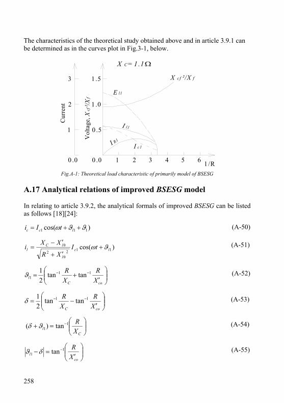
258
The characteristics of the theoretical study obtained above and in article 3.9.1 can be determined as in the curves plot in Fig.3-1, below.
Cur
rent
0 .5
1 .0
1 .5
0 .0
1
2
3V
olta
ge, X
cf²/X
f
X cf ²/X f
I R1
X C = 1 .1
I l1
I c1
E l1
1 /R0 .0 1 2 3 4 5 6
Fig.A-1: Theoretical load characteristic of primarily model of BSESG A.17 Analytical relations of improved BSESG model In relating to article 3.9.2, the analytical formals of improved BSESG can be listed as follows [18][24]:
)cos( 111 ϑϑω ++= lcc tIi (A-50)
)cos( 1120
2
0lc
l
lCl tI
XR
XXi ϑω +
′+
′−= (A-51)
⎟⎟⎠
⎞⎜⎜⎝
⎛′
+= −−
coCl X
RXR 11
1 tantan21ϑ (A-52)
⎟⎟⎠
⎞⎜⎜⎝
⎛′
−= −−
coC XR
XR 11 tantan
21δ (A-53)
⎟⎟⎠
⎞⎜⎜⎝
⎛=+ −
Cl X
R11 tan)( ϑδ (A-54)
⎟⎟⎠
⎞⎜⎜⎝
⎛′
=− −
col X
R11 tanδϑ (A-55)
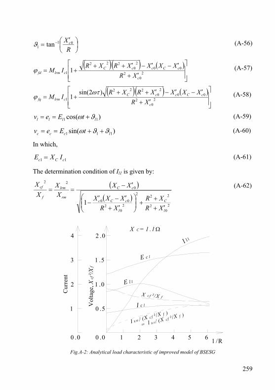
259
⎟⎠⎞
⎜⎝⎛ ′
= −
RX c01
1 tanϑ (A-56)
( )( ) ( )⎥⎥⎦
⎤
⎢⎢⎣
⎡
′+
′−′−′+++= 2
02
002
0222
1 1c
cCccCclrmfd XR
XXXXRXRIMϕ (A-57)
( )( ) ( )⎥⎥⎦
⎤
⎢⎢⎣
⎡
′+
′−′−′+++= 2
02
002
0222
1)2sin(
1c
cCccCclrmfq XR
XXXXRXRIM
ωτϕ (A-58)
)cos( 11 llll tEev ϑω +== (A-59)
)sin( 111 lccc tEev ϑϑω ++== (A-60)
In which,
11 cCc IXE = (A-61)
The determination condition of Il1 is given by:
( )( )
20
2
222
20
200
022
1l
C
l
cCc
cC
rm
lrm
f
cf
XRXR
XRXXX
XXXX
XX
′++
+⎟⎟⎠
⎞⎜⎜⎝
⎛′+
′−′−
′−== (A-62)
Cur
rent
0 .5
1 .0
1 .5
2 .0
0 .0
1
2
3
4
Vol
tage
, Xcf
²/Xf
E l 1
X c f ² /X f
I c 1
E c 1
I l1
I R M / (X c f ² /X f )
= I R A / (X c f ² /X f )
X C = 1 .1 Ω
1 /R0 .0 1 2 3 4 5 6
Fig.A-2: Analytical load characteristic of improved model of BSESG
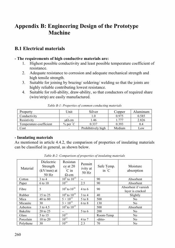
260
Appendix B: Engineering Design of the Prototype Machine
B.1 Electrical materials - The requirements of high conductive materials are:
1. Highest possible conductivity and least possible temperature coefficient of resistance.
2. Adequate resistance to corrosion and adequate mechanical strength and high tensile strength.
3. Suitable for joining by brazing/ soldering/ welding so that the joints are highly reliable contributing lowest resistance.
4. Suitable for roll-ability, draw-ability, so that conductors of required share (wire/strip) are easily manufactured.
Table B-1: Properties of common conducting materials
Property Unit Silver Copper Aluminum Conductivity - 1.0 0.975 0.585 Resistivity μΩ.cm 1.46 1.777 2.826 Temperature-coefficient % per °C 0.337 0.393 0.4 Cost - Prohibitively high Medium Low
- Insulating materials As mentioned in article 4.4.2, the comparison of properties of insulating materials can be classified in general, as shown below.
Table B-2: Comparison of properties of insulating materials
Material
Dielectric Strength
(kV/mm) at 50 Hz
Resistance at 20
°C in Ω-cm
Permittivity at 50 Hz
Safe Temp. in °C
Moisture absorption
Cotton 3 to 4 109 to 1013 -- 90 Absorbent Paper 6 to 10 1015 2.5 90 Absorbent
Fibre 5 109 to 1018 4 to 6 90 Absorbent if varnish layer is cracked
Rubber 15 to 25 106 to 1015 3 to 4 40 Slightly Mica 40 to 80 5 × 10¹³ 5 to 8 500 No Micanite 30 3 × 10¹³ 6 to 8 130 No Asbestos 3 to 4.5 109 to 1015 500 Absorbent Bakelite 20 to 25 -- 5 to 6 200 No Glass 5 to 15 1015 Room-Temp No Porcelain 10 to 20 1013 4 to 7 -ditto- No Polythene 30 1016 2.3 70 No
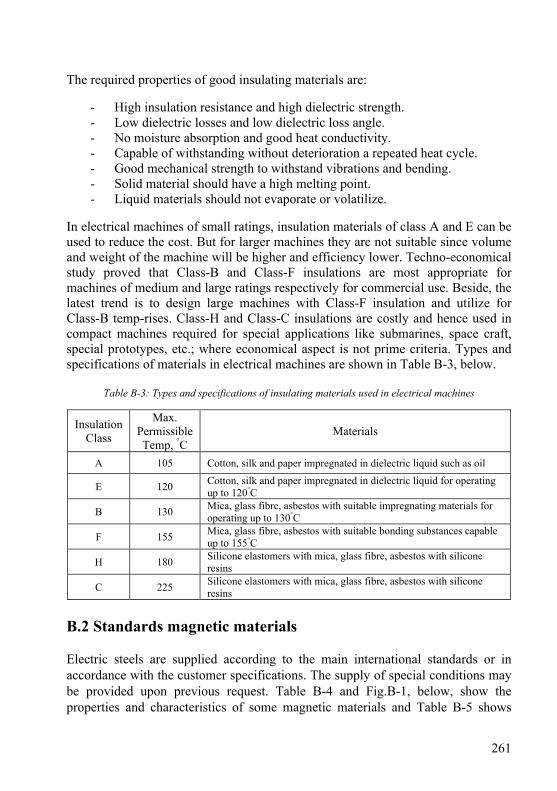
261
The required properties of good insulating materials are:
- High insulation resistance and high dielectric strength. - Low dielectric losses and low dielectric loss angle. - No moisture absorption and good heat conductivity. - Capable of withstanding without deterioration a repeated heat cycle. - Good mechanical strength to withstand vibrations and bending. - Solid material should have a high melting point. - Liquid materials should not evaporate or volatilize.
In electrical machines of small ratings, insulation materials of class A and E can be used to reduce the cost. But for larger machines they are not suitable since volume and weight of the machine will be higher and efficiency lower. Techno-economical study proved that Class-B and Class-F insulations are most appropriate for machines of medium and large ratings respectively for commercial use. Beside, the latest trend is to design large machines with Class-F insulation and utilize for Class-B temp-rises. Class-H and Class-C insulations are costly and hence used in compact machines required for special applications like submarines, space craft, special prototypes, etc.; where economical aspect is not prime criteria. Types and specifications of materials in electrical machines are shown in Table B-3, below.
Table B-3: Types and specifications of insulating materials used in electrical machines
Insulation Class
Max. Permissible Temp, °C
Materials
A 105 Cotton, silk and paper impregnated in dielectric liquid such as oil
E 120 Cotton, silk and paper impregnated in dielectric liquid for operating up to 120°C
B 130 Mica, glass fibre, asbestos with suitable impregnating materials for operating up to 130°C
F 155 Mica, glass fibre, asbestos with suitable bonding substances capable up to 155°C
H 180 Silicone elastomers with mica, glass fibre, asbestos with silicone resins
C 225 Silicone elastomers with mica, glass fibre, asbestos with silicone resins
B.2 Standards magnetic materials Electric steels are supplied according to the main international standards or in accordance with the customer specifications. The supply of special conditions may be provided upon previous request. Table B-4 and Fig.B-1, below, show the properties and characteristics of some magnetic materials and Table B-5 shows

262
types of non-oriented electrical steels according to international standards, where the magnetic loss is at 1.5 T / 50 Hz [Ref. 6, chapter 4].
Table B-4: Properties of some soft magnetic materials, the core losses are given at 50 Hz, 1.5 Wb/m2
Material Bsat [T]
ρ [µΩ.m] µr,max λ [W/mK] P
[W/kg] Non-oriented electrical steels 2.1 0.4 5000 40 5 METGLAS™ 2605C 1.8 1.2 400000 9 0.5 Permendur (Fe49-Co49-2V) 2.34 0.35 50000 12 1.4 SMC-composite SOMALOY™500 with 0.5 % KENOLUBE™ 2.0 30 500 17 15
NiZn ferrites 0.35 1×10⁶ 4000 3.5-5×10⁻³ - MnZn ferrites 0.5 0.2×10⁶ 6000 3.5-5×10⁻³ - Chrome Core® 8 Alloy 1.86 0.49 3100 - -
Fig.B-1: B-H curve of different type of magnetic steels
Table B-5: International standard specifications of electrical steel materials
ABNT
NM71-2000
AISI ASTM
A677 M
JIS
2552-2000
DIN
EN 10106
Thick.
(mm)
Grade (W/kg) Grade Grade (W/kg) Grade (W/kg) Grade (W/kg)
65F 770M 6.10 - 64F 320 5.59 - - M600-65A 5.30
65F 600M 4.70 - 64F 275 4.79 - - M470-65A 4.70
65F 540M 4.25 - 64F 235 4.18 - - - -
0.64
65F 500M 3.95 - 64F 225 3.92 - - M400-65A 4.00
0 1 0 0 0 2 0 0 0 3 0 0 0 4 0 0 0 5 0 0 0 6 0 0 0 7 0 0 0 8 0 0 0 9 0 0 0 1 0 0 0 0H (A /m )
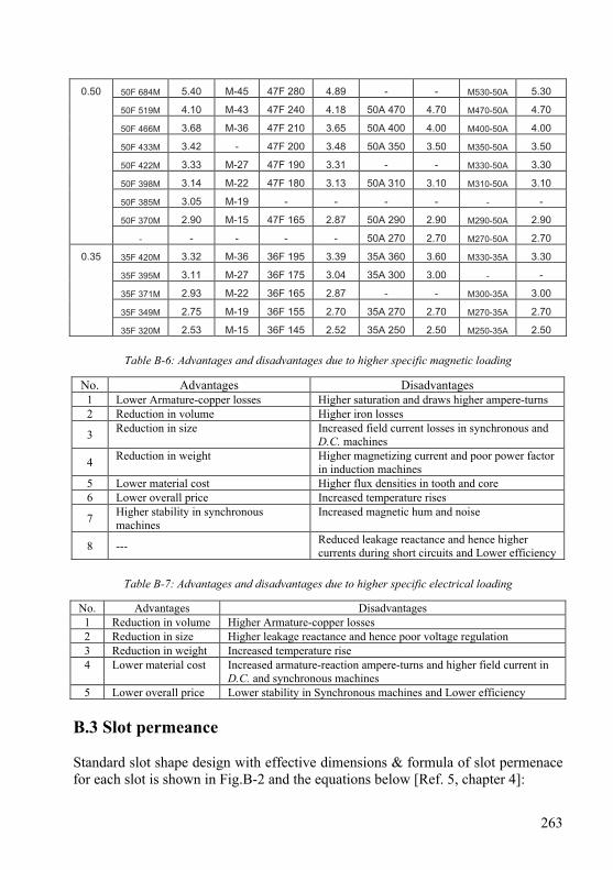
263
50F 684M 5.40 M-45 47F 280 4.89 - - M530-50A 5.30
50F 519M 4.10 M-43 47F 240 4.18 50A 470 4.70 M470-50A 4.70
50F 466M 3.68 M-36 47F 210 3.65 50A 400 4.00 M400-50A 4.00
50F 433M 3.42 - 47F 200 3.48 50A 350 3.50 M350-50A 3.50
50F 422M 3.33 M-27 47F 190 3.31 - - M330-50A 3.30
50F 398M 3.14 M-22 47F 180 3.13 50A 310 3.10 M310-50A 3.10
50F 385M 3.05 M-19 - - - - - -
50F 370M 2.90 M-15 47F 165 2.87 50A 290 2.90 M290-50A 2.90
0.50
- - - - - 50A 270 2.70 M270-50A 2.70
35F 420M 3.32 M-36 36F 195 3.39 35A 360 3.60 M330-35A 3.30
35F 395M 3.11 M-27 36F 175 3.04 35A 300 3.00 - -
35F 371M 2.93 M-22 36F 165 2.87 - - M300-35A 3.00
35F 349M 2.75 M-19 36F 155 2.70 35A 270 2.70 M270-35A 2.70
0.35
35F 320M 2.53 M-15 36F 145 2.52 35A 250 2.50 M250-35A 2.50
Table B-6: Advantages and disadvantages due to higher specific magnetic loading
No. Advantages Disadvantages 1 Lower Armature-copper losses Higher saturation and draws higher ampere-turns 2 Reduction in volume Higher iron losses
3 Reduction in size Increased field current losses in synchronous and D.C. machines
4 Reduction in weight Higher magnetizing current and poor power factor in induction machines
5 Lower material cost Higher flux densities in tooth and core 6 Lower overall price Increased temperature rises
7 Higher stability in synchronous machines
Increased magnetic hum and noise
8 --- Reduced leakage reactance and hence higher currents during short circuits and Lower efficiency
Table B-7: Advantages and disadvantages due to higher specific electrical loading
No. Advantages Disadvantages 1 Reduction in volume Higher Armature-copper losses 2 Reduction in size Higher leakage reactance and hence poor voltage regulation 3 Reduction in weight Increased temperature rise 4 Lower material cost Increased armature-reaction ampere-turns and higher field current in
D.C. and synchronous machines 5 Lower overall price Lower stability in Synchronous machines and Lower efficiency
B.3 Slot permeance Standard slot shape design with effective dimensions & formula of slot permenace for each slot is shown in Fig.B-2 and the equations below [Ref. 5, chapter 4]:

264
Fig.B-2: Slot permeance leakage factor for standard slot design B.4 Prototype-BCESG plots of designed parts and subassemblies B.4.1 Two-scale stator lamination
0.70
2.80
9.70
7.5°
2X R0.60
2X R3.80
21.00
6.002X R2.00
1.00 * " C "
Detail " C "4 Places Equally Spaced Scale 2:1
2.5
8.0
Detail " B "48 Slots Equally Spaced Scale 2:1
48X 7.5°
5.48 *
Ø4.07+0.05 0.00
Ø257.00
30.0°
15.0°
4X 90.0°
Ø263.000+0.100+0.075
Ø191.00 0.00-0.05
15.0 *
0.1 A
60.00°
A
Uni Kassel - FB- 16Do not scale Drawing IEE/ EVS
Scale
(Material, Semi-finished) Non oriented Electrcial Steel
, 50 Hz. (Number) 380 PiecesDate
20102010Design
NormCheck
L.IZZATS.HEIER
Name
1:1 (Weight) 96 grams
1-1
Page
sheet 0.50 thick. Max. core losses 4.9 w/kg at 1.5
Dimensions in MillimetersTolerances Free dimensions Dimension: Angles: .x +/- .2 +/- .5° .xx +/- .1
Notes- * : For Information.- Remove all burrs greater than 0.03 mm.
" B "
4X 130.50
6X
6X
Equally Spaced On a Ø257.00
0.1 A
First Angle Projection
Fig.B-3: Two-scale drawing of the stator lamination of BCESG
2
4
21
3
1
2
1
1 23 b
hbb
hbh
bh
s ++
++=σλ2
4
32
3
3
2
1
1 23 b
hbb
hbh
bh
s ++
++=σλ
( ) 2
4
32
3
3
2
31
1 23
2bh
bbh
bh
bbh
s ++
+++
=σλ1
1623.0bhkrds +=σλ
( ) 2
4
31
1 623.03
2bh
bbh
s +++
=σλ4
133 1
3
3
1 +⎟⎟⎠
⎞⎜⎜⎝
⎛+=
βλσ bh
bh
s
0.132
<< β
krd > 1
(a) (b)
(c) (d)
(e) (f)
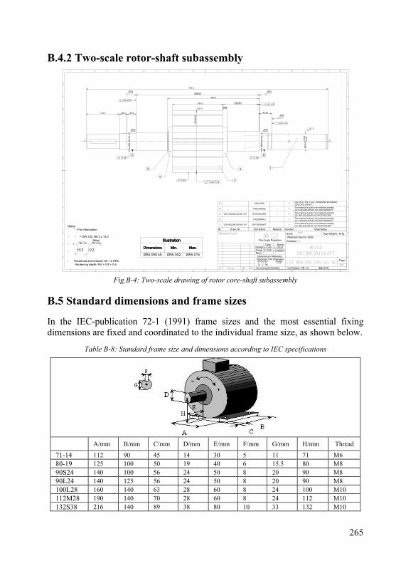
265
B.4.2 Two-scale rotor-shaft subassembly
+0.3 -0.2
First Angle Projection
Uni Kassel - FB- 16Do not scale Drawing IEE/ EVS
Scale
(Material) See the Table
(Number) 1
Date
01.201101.2011Design
NormCheck
L.IZZATS.HEIER
Name
1:1 (App.Weight) 38 kg
1-1
Page
Rz 1.6 Rz 0.8Milled
Notes- * : For Information.
- = DIN 332, B6.3 x 13.2
- ( )
-
- Hardened and relaxed: 60 + 4 HRC Hardening depth: Eht = 0.8 + 0.4
Illustration
Dimensions Min. Max.
Ø55.000 k5 Ø55.002 Ø55.015
Nr. Draw. Nr. Part Name Material Number Table Notes
1 G3-180L290-205-60-167 ROTORSHAFT - 1The material is given in the referred drawingG3-180L290-205-60-167/ ROTORSHAFT
2 FIXEDRING1 - 1The material is given in the referred drawingG11-180L290-205-60-167/ ROTORSHAFT
3 G2-180L290-205-60-167 ROTORCORE - 1The material is given in the referred drawingG2-180L290-205-60-167/ ROTORCORE
4 FIXEDRING2 - 1The material is given in the referred drawingG12-180L290-205-60-167/ ROTORSHAFT
5 - CIRCLIPS1 - 1Dia. 55.8 x Thk. 2 mm, STANDARD EXTERNALCIRCLIPS: DIN 471 .
Dimensions in MillimetersTolerances Free dimensions Dimension: Angles: .x +/- .2 +/- .5° .xx +/- .05
770.5
30.026.0110.0 42.50
190.5
14.0
Ø55
.000
k5
Rz 0.8Milled
409.00
120.50
Ø55
. 000
k5
Rz 0.8Milled Rz 1.6
z
Rz 0.8Milled
Rz 0.8Milled
304.0
Rz 1.6
A B
0.02 A B
0.02 0.02
0.02 A B
0.02 A B
0.02
12
3
4
5
Ø50
.00+
0.04
0.0
0
z
Rz 0.8Milled
0.02 A B
.00
Ø18
9
Fig.B-4: Two-scale drawing of rotor core-shaft subassembly B.5 Standard dimensions and frame sizes In the IEC-publication 72-1 (1991) frame sizes and the most essential fixing dimensions are fixed and coordinated to the individual frame size, as shown below.
Table B-8: Standard frame size and dimensions according to IEC specifications
A/mm B/mm C/mm D/mm E/mm F/mm G/mm H/mm Thread
71-14 112 90 45 14 30 5 11 71 M6 80-19 125 100 50 19 40 6 15.5 80 M8 90S24 140 100 56 24 50 8 20 90 M8 90L24 140 125 56 24 50 8 20 90 M8 100L28 160 140 63 28 60 8 24 100 M10 112M28 190 140 70 28 60 8 24 112 M10 132S38 216 140 89 38 80 10 33 132 M10
266
132M38 216 178 89 38 80 10 33 132 M10 160M42 254 210 108 42 110 12 37 160 M12 160L42 254 254 108 42 110 12 37 160 M12 180M48 279 241 121 48 110 14 42.5 180 M12 180L48 279 279 121 48 110 14 42.5 180 M12 200M55 318 267 133 55 110 16 49 200 M16 200L55 318 305 133 55 110 16 49 200 M16
B.6 Determination of rotor slots area Two kinds of slots are existed in rotor stamp, as explained in article 4.5.4.2. The area of each one are depends on load current, number of effective turns, current density, specific electric load and slot fullness factor. The rearranging and derivations to obtain the slot area are detailed below. B.6.1 Slot area type-S2n Substituting equation (4-22) into equation (4-21) and the winding cross-section area in terms of rotor current density from equation (4-73), gives:
2222
2JqpK
ITAnns
rarans = ;
Also, substituting from equation (4-49) instead of the term (Tra Ira), above, yields slot area in terms of auxiliary rotor M.M.F. Then substituting equation (4-48) into the resultant equation gives the rotor slot area type-S2n in terms of effective number of turns of stator load winding and rated current:
122
22
11122 sin
8.1ψ
wranns
wllns KJqpK
KTIaA = (B-1)
B.6.2 Slot area type-S2s From equations (4-44) &(4-46), the following can be obtained at zero power factor,
s
rmrmpdwccc
aIT
pKTI
2
118.1=
ρ (B-2)
Substituting the definition of windings Tc1 and Trmp from equations (4-37) and (4-46), respectively; also, the definition of currents Ic1 and Irm from equations (4-36) and (4-73), respectively; into the above relation gives:
22221118.1 JNAaKqZI scscsdwcsz =ρ ; In the above equation, the term Iz1 Zs1 can be substituted in terms of specific electric load, referred to equation (4-35) and the term Ac2s Nc2s can be substitute from equation (4-31) in terms of slot fullness factor for slots type-S2s to obtain the slot surface area, as in the given equation, below.
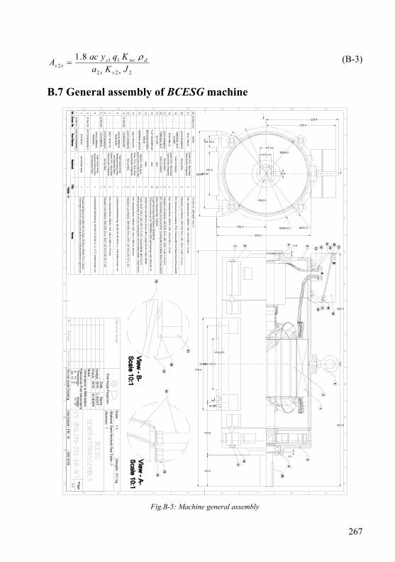
267
222
112
8.1JKaKqyacA
sss
dwcsss
ρ= (B-3)
B.7 General assembly of BCESG machine
304.0254.00
228.00282.0
4X
Ø13.0
2X 39.0
144.0
156.0
173.5
778.0
22G
106-011cK
EY
S-
112 x 80 x 8 , U
NI-6604 F
orm C
21-
BO
LT M
6x10G
rade 10.9 - Alloy S
teel,Q
uenched & T
empered
4H
ex. Standard B
olts, DIN
931 / 933 , Dim
.s: M6 x L 10 m
m
20-
LOC
K W
AS
HE
R4
Spring S
teel4
Standard Lock W
asher, DIN
127B, D
im.s: M
6, ( Øi 6.1 x Ø
o 11.8 ) mm
19-
TE
RM
INA
L BO
XC
OV
ER
Cast-iron design
1IE
C T
erminal box enclosure, IP
54, Draw
ing:B6/ K
urt Maier M
otor-Press G
mbH
18-
BO
LT M
6x12G
rade 10.9 - Alloy S
teel,Q
uenched & T
empered
4H
ex. Standard B
olts, DIN
931 / 933 , Dim
.s: M6 x L 12 m
m
17-
LOC
K W
AS
HE
R3
Spring S
teel4
Standard Lock W
asher, DIN
127B, D
im.s: M
6, ( Øi 6.1 x Ø
o 11.8 ) mm
16-
TE
RM
INA
L BO
XC
ast-iron design1
IEC
Term
inal Box E
nclosure IP54, D
rawing:B
6/ Kurt M
aier Motor-P
ress Gm
bH
15-
NU
T M
4Z
ink12
Metric S
tandard Nut - D
IN934
14-
FLA
T W
AS
HE
R M
4Z
ink12
Large Flat (C
oach Bolt) W
asher (DIN
9021A).
They are m
ounted on the TE
RM
INA
L EN
D and fixed later w
ith NU
Tat N
r.15.
13-
MA
CH
INE
SC
RE
WM
4x20N
ylon4
Slotted P
an Head M
achine Screw
: M4 x Length 20 m
m. N
ylon DIN
85
12-
TE
RM
INA
L BO
AR
DM
elamin, 20%
glassreinforced for D
IN 53 480
2T
ype: 40 25 / Dim
.s: (40 x 25 x 11.7) mm
, Term
inal Bolts: M
4 x10 mm
,M
ounting Holes: Ø
4.5 mm
. Draw
ing Set: G
1/ Kurt M
aier Motor - P
ress Gm
bH
11-
BO
LT M
10x100C
lass 10.9 - Alloy S
teel,Q
uenched & T
empered
4H
ex. Standard B
olts, DIN
931 / 933 , Dim
.s: M10 x L 100 m
m
10-
LOC
K W
AS
HE
R2
Spring S
teel4
Standard Lock W
asher, DIN
127B, D
im.s: M
10, ( Øi 10.2 x Ø
o 18.1 ) mm
9G
106-008C
OV
ER
FR
ON
T-
1
8-
WA
VE
SP
RIN
GW
AS
HE
R2
High C
arbon finelytem
pered Spring S
teeland S
tainless Steel
1Loading front B
all Bearing, (Ø
o 89.38 x Øi 69.60 x L. 5.94 w
ithout-load) mm
7-
BO
LT M
10x170G
rade 10.9 - Alloy S
teel,Q
uenched & T
empered
4H
ex. Standard B
olts, DIN
931 / 933 , Dim
.s: M10 x L 170 m
m
6-
LOC
K W
AS
HE
R1
Spring S
teel4
Standard Lock W
asher, DIN
127B, D
im.s: M
10, ( Øi 10.2 x Ø
o 18.1 ) mm
5G
106-009C
OV
ER
BA
CK
-1
4-
WA
VE
SP
RIN
GW
AS
HE
R1
High C
arbon finelytem
pered Spring S
teeland S
tainless Steel
1Loading back B
all Bearing, (Ø
o 84.53 x Øi 66.12 x L. 5.77 w
ithout-load) mm
3G
106-010R
OT
OR
AS
SE
MB
LY-
1
2-
EY
E B
OLT
Zinc P
lated Steel
1F
orged machinery eye bolts w
ith shoulder, Ø12m
m x P
itch1.75 x L. 24mm
,T
otal length 92.4 mm
. Steel is zinc plated for m
oderate protection against rust.
1G
106-011S
TA
TO
RA
SS
EM
BLY
-1
Nr.
Draw
. Nr.
Part N
ame
Material
Qty.
Notes
Table -1-
3.0
3.0
103.0
Ø308.00 Ø337.0
228.4
220.0
Ø280.0
296.0
Ø42.0
45.3
12.0
37.0
Uni K
assel - FB
- 16D
o not scale Draw
ingIE
E/ E
VS
Scale
(Material, S
emi-finished) S
ee Table -1-
(Num
ber) 1
Date
20102010
Design
Norm
Check
L.IZZ
AT
S.H
EIE
R
Nam
e
1:1(W
eight) 611 kg1-1
Page
Dim
ensions in Millim
etersT
olerances Free dim
ensions D
imension: A
ngles: .x +
/- .2 +/- .5°
.xx +/- .1
First A
ngle Projection
16.0
170.0
364.5
403.5
A
B
21
20
19
View
- A-
Scale 10:1
View
- B-
Scale 10:1
1
8
22
10
11
16
17
18
1915
14 20 21
1213
5
467
16
1215
14
2
3
9
Fig.B-5: Machine general assembly
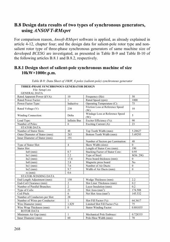
268
B.8 Design data results of two types of synchronous generators, using ANSOFT-RMxprt
For comparison reason, Ansoft-RMxprt software is applied, as already explained in article 4-12, chapter four; and the design data for salient-pole rotor type and non-salient rotor type of three-phase synchronous generators of same machine size of developed BCESG are investigated, as presented in Table B-9 and Table B-10 of the following articles B.8.1 and B.8.2, respectively. B.8.1 Design sheet of salient-pole synchronous machine of size
10kW×1000r.p.m.
Table B-9: Data Sheet of 10kW, 6 poles (salient-pole) synchronous generator
THREE-PHASE SYNCHRONOUS GENERATOR DESIGN File: Setup1.res GENERAL DATA Rated Apparent Power (kVA): 10 Frequency (Hz): 50 Rated Power Factor: 1 Rated Speed (rpm): 1000 Power Factor Type: Inductive Operating Temperature (C): 75
Rated Voltage (V): 230 Friction Loss at Reference Speed (W): 10
Winding Connection: Delta Windage Loss at Reference Speed (W): 5
Load Type: Infinite Bus Exciter Efficiency (%): 90 Number of Poles: 6 Exciting Current (A): 23 STATOR DATA Number of Stator Slots: 48 Top Tooth Width (mm): 5.28627 Outer Diameter of Stator (mm): 263 Bottom Tooth Width (mm): 5.49295 Inner Diameter of Stator (mm): 191 Number of Sectors per Lamination: 48 Type of Stator Slot: 4 Skew Width (slots): 0 Stator Slot Length of Stator Core (mm): 190 hs0 (mm): 0.7 Stacking Factor of Stator Core: 0.95 hs1 (mm): 2.2 Type of Steel: M36_29G hs2 (mm): 17.6 Press board thickness (mm): 0 bs0 (mm): 2.8 Magnetic press board No bs1 (mm): 7.6 Number of Air Ducts: 0 bs2 (mm): 9.7 Width of Air Ducts (mm): 0 rs (mm): 0.6 STATOR-WINDING DATA End Length Adjustment (mm): 150 Wedge Thickness (mm): 2.2 End-Coil Clearance (mm): 2 Slot Liner Thickness (mm): 0.2 Number of Parallel Branches: 2 Layer Insulation (mm): 0.2 Type of Coils: 21 Slot Area (mm2): 174.508 Coil Pitch: 6 Net Slot Area (mm2): 145.532 Number of Conductors per Slot: 28 Number of Wires per Conductor: 1 Slot Fill Factor (%): 64.3617 Wire Diameter (mm): 1.829 Limited Slot Fill Factor (%): 75 Wire Wrap Thickness (mm): 0 Stator Winding Factor: 0.881035 ROTOR DATA Minimum Air Gap (mm): 1 Mechanical Pole Embrace: 0.728335 Inner Diameter (mm): 60 Pole-Shoe Width (mm): 70
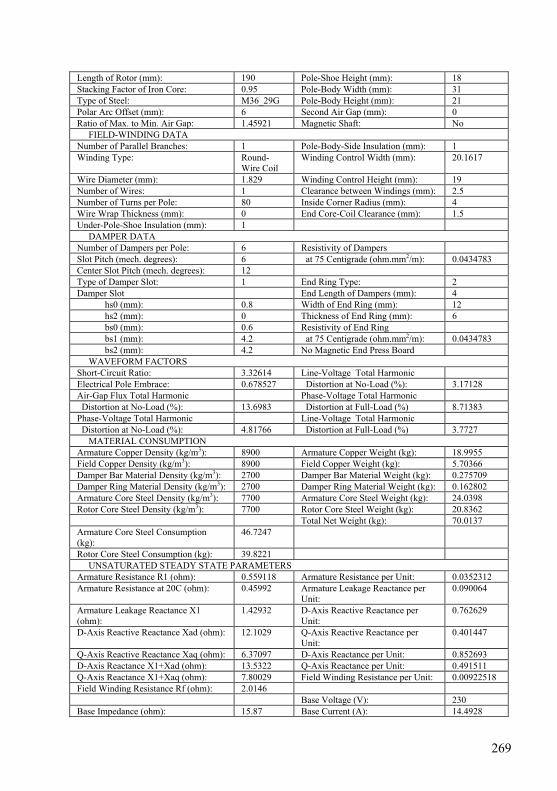
269
Length of Rotor (mm): 190 Pole-Shoe Height (mm): 18 Stacking Factor of Iron Core: 0.95 Pole-Body Width (mm): 31 Type of Steel: M36_29G Pole-Body Height (mm): 21 Polar Arc Offset (mm): 6 Second Air Gap (mm): 0 Ratio of Max. to Min. Air Gap: 1.45921 Magnetic Shaft: No FIELD-WINDING DATA Number of Parallel Branches: 1 Pole-Body-Side Insulation (mm): 1 Winding Type: Round-
Wire Coil Winding Control Width (mm): 20.1617
Wire Diameter (mm): 1.829 Winding Control Height (mm): 19 Number of Wires: 1 Clearance between Windings (mm): 2.5 Number of Turns per Pole: 80 Inside Corner Radius (mm): 4 Wire Wrap Thickness (mm): 0 End Core-Coil Clearance (mm): 1.5 Under-Pole-Shoe Insulation (mm): 1 DAMPER DATA Number of Dampers per Pole: 6 Resistivity of Dampers Slot Pitch (mech. degrees): 6 at 75 Centigrade (ohm.mm2/m): 0.0434783 Center Slot Pitch (mech. degrees): 12 Type of Damper Slot: 1 End Ring Type: 2 Damper Slot End Length of Dampers (mm): 4 hs0 (mm): 0.8 Width of End Ring (mm): 12 hs2 (mm): 0 Thickness of End Ring (mm): 6 bs0 (mm): 0.6 Resistivity of End Ring bs1 (mm): 4.2 at 75 Centigrade (ohm.mm2/m): 0.0434783 bs2 (mm): 4.2 No Magnetic End Press Board WAVEFORM FACTORS Short-Circuit Ratio: 3.32614 Line-Voltage Total Harmonic Electrical Pole Embrace: 0.678527 Distortion at No-Load (%): 3.17128 Air-Gap Flux Total Harmonic Phase-Voltage Total Harmonic Distortion at No-Load (%): 13.6983 Distortion at Full-Load (%) 8.71383 Phase-Voltage Total Harmonic Line-Voltage Total Harmonic Distortion at No-Load (%): 4.81766 Distortion at Full-Load (%) 3.7727 MATERIAL CONSUMPTION Armature Copper Density (kg/m3): 8900 Armature Copper Weight (kg): 18.9955 Field Copper Density (kg/m3): 8900 Field Copper Weight (kg): 5.70366 Damper Bar Material Density (kg/m3): 2700 Damper Bar Material Weight (kg): 0.275709 Damper Ring Material Density (kg/m3): 2700 Damper Ring Material Weight (kg): 0.162802 Armature Core Steel Density (kg/m3): 7700 Armature Core Steel Weight (kg): 24.0398 Rotor Core Steel Density (kg/m3): 7700 Rotor Core Steel Weight (kg): 20.8362 Total Net Weight (kg): 70.0137 Armature Core Steel Consumption (kg):
46.7247
Rotor Core Steel Consumption (kg): 39.8221 UNSATURATED STEADY STATE PARAMETERS Armature Resistance R1 (ohm): 0.559118 Armature Resistance per Unit: 0.0352312 Armature Resistance at 20C (ohm): 0.45992 Armature Leakage Reactance per
Unit: 0.090064
Armature Leakage Reactance X1 (ohm):
1.42932 D-Axis Reactive Reactance per Unit:
0.762629
D-Axis Reactive Reactance Xad (ohm): 12.1029 Q-Axis Reactive Reactance per Unit:
0.401447
Q-Axis Reactive Reactance Xaq (ohm): 6.37097 D-Axis Reactance per Unit: 0.852693 D-Axis Reactance X1+Xad (ohm): 13.5322 Q-Axis Reactance per Unit: 0.491511 Q-Axis Reactance X1+Xaq (ohm): 7.80029 Field Winding Resistance per Unit: 0.00922518 Field Winding Resistance Rf (ohm): 2.0146 Base Voltage (V): 230 Base Impedance (ohm): 15.87 Base Current (A): 14.4928
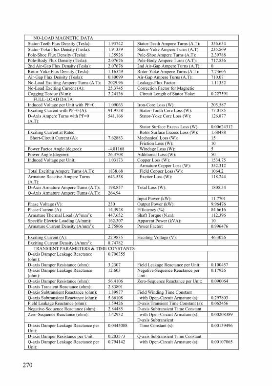
270
NO-LOAD MAGNETIC DATA Stator-Teeth Flux Density (Tesla): 1.93742 Stator-Teeth Ampere Turns (A.T): 356.634 Stator-Yoke Flux Density (Tesla): 1.91339 Stator-Yoke Ampere Turns (A.T): 235.569 Pole-Shoe Flux Density (Tesla): 1.35926 Pole-Shoe Ampere Turns (A.T): 2.39788 Pole-Body Flux Density (Tesla): 2.07676 Pole-Body Ampere Turns (A.T): 717.556 2nd Air-Gap Flux Density (Tesla): 2.07676 2nd Air-Gap Ampere Turns (A.T): 0 Rotor-Yoke Flux Density (Tesla): 1.16529 Rotor-Yoke Ampere Turns (A.T): 7.73605 Air-Gap Flux Density (Tesla): 0.80099 Air-Gap Ampere Turns (A.T): 710.07 No-Load Exciting Ampere Turns (A.T): 2029.96 Leakage-Flux Factor: 1.11352 No-Load Exciting Current (A): 25.3745 Correction Factor for Magnetic Cogging Torque (N.m): 2.24136 Circuit Length of Stator Yoke: 0.227591 FULL-LOAD DATA Induced Voltage per Unit with PF=0: 1.09063 Iron-Core Loss (W): 205.587 Exciting Current with PF=0 (A): 91.9758 Stator-Tooth Core Loss (W): 77.0185 D-Axis Ampere Turns with PF=0 (A.T):
541.166 Stator-Yoke Core Loss (W): 126.877
Stator Surface Excess Loss (W): 0.00624312 Exciting Current at Rated Rotor Surface Excess Loss (W): 1.68488 Short-Circuit Current (A): 7.62883 Mechanical Loss (W): 15 Friction Loss (W): 10 Power Factor Angle (degree): -4.81168 Windage Loss (W): 5 Power Angle (degree): 26.3708 Additional Loss (W): 50 Induced Voltage per Unit: 1.03173 Copper Loss (W): 1534.75 Armature Copper Loss (W): 352.312 Total Exciting Ampere Turns (A.T): 1838.68 Field Copper Loss (W): 1064.2 Armature Reactive Ampere Turns (A.T):
643.538 Exciter Loss (W): 118.244
D-Axis Armature Ampere Turns (A.T): 198.857 Total Loss (W): 1805.34 Q-Axis Armature Ampere Turns (A.T): 264.94 Input Power (kW): 11.7701 Phase Voltage (V): 230 Output Power (kW): 9.96476 Phase Current (A): 14.4928 Efficiency (%): 84.6616 Armature Thermal Load (A2/mm3): 447.652 Shaft Torque (N.m): 112.396 Specific Electric Loading (A/mm): 162.307 Apparent Power (kVA): 10 Armature Current Density (A/mm2): 2.75806 Power Factor: 0.996476 Exciting Current (A): 22.9835 Exciting Voltage (V): 46.3026 Exciting Current Density (A/mm2): 8.74782 TRANSIENT PARAMETERS & TIME CONSTANTS D-axis Damper Leakage Reactance (ohm):
0.706355
D-axis Damper Resistance (ohm): 3.2307 Field Leakage Reactance per Unit: 0.100457 Q-axis Damper Leakage Reactance (ohm):
12.603 Negative-Sequence Reactance per Unit:
0.17926
Q-axis Damper Resistance (ohm): 56.4106 Zero-Sequence Reactance per Unit: 0.090064 D-axis Transient Reactance (ohm): 2.83801 D-axis Subtransient Reactance (ohm): 1.89977 Field Winding Time Constant Q-axis Subtransient Reactance (ohm): 5.66108 with Open-Circuit Armature (s): 0.297803 Field Leakage Reactance (ohm): 1.59426 D-axis Transient Time Constant (s): 0.062456 Negative-Sequence Reactance (ohm): 2.84485 D-axis Subtransient Time Constant Zero-Sequence Reactance (ohm): 1.42932 with Open-Circuit Armature (s): 0.00208389 D-axis Subtransient D-axis Damper Leakage Reactance per Unit:
0.0445088 Time Constant (s): 0.00139496
D-axis Damper Resistance per Unit: 0.203573 Q-axis Subtransient Time Constant Q-axis Damper Leakage Reactance per Unit:
0.794142 with Open-Circuit Armature (s): 0.00107065
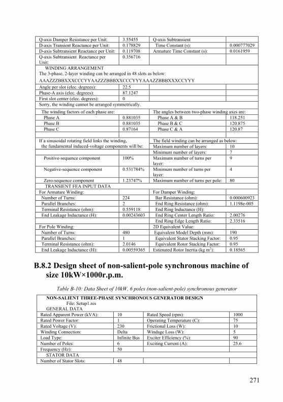
271
Q-axis Damper Resistance per Unit: 3.55455 Q-axis Subtransient D-axis Transient Reactance per Unit: 0.178829 Time Constant (s): 0.000777029 D-axis Subtransient Reactance per Unit: 0.119708 Armature Time Constant (s): 0.0161959 Q-axis Subtransient Reactance per Unit:
0.356716
WINDING ARRANGEMENT The 3-phase, 2-layer winding can be arranged in 48 slots as below:
AAAZZZBBXXXCCCYYAAZZZBBBXXCCCYYYAAAZZBBBXXXCCYYY
Angle per slot (elec. degrees): 22.5 Phase-A axis (elec. degrees): 87.1247 First slot center (elec. degrees): 0 Sorry, the winding cannot be arranged symmetrically. The winding factors of each phase are: The angles between two-phase winding axes are: Phase A 0.881035 Phase A & B 118.251 Phase B 0.881035 Phase B & C 120.875 Phase C 0.87164 Phase C & A 120.87
The field winding can be arranged as below: If a sinusoidal rotating field links the winding, the fundamental induced-voltage components will be: Maximum number of layers: 10 Minimum number of layers: 7 Positive-sequence component 100% Maximum number of turns per
layer: 9
Negative-sequence component 0.531784% Minimum number of turns per layer:
4
Zero-sequence component 1.23747% Maximum number of turns per pole: 80 TRANSIENT FEA INPUT DATA For Armature Winding: For Damper Winding: Number of Turns: 224 Bar Resistance (ohm): 0.000600923 Parallel Branches: 2 End Ring Resistance (ohm): 1.1198e-005 Terminal Resistance (ohm): 0.559118 End Ring Inductance (H): End Leakage Inductance (H): 0.00243603 End Ring Center Length Ratio: 2.00276 End Ring Edge Length Ratio: 2.33516 For Pole Winding: 2D Equivalent Value: Number of Turns: 480 Equivalent Model Depth (mm): 190 Parallel Branches: 1 Equivalent Stator Stacking Factor: 0.95 Terminal Resistance (ohm): 2.0146 Equivalent Rotor Stacking Factor: 0.95 End Leakage Inductance (H): 0.00559365 Estimated Rotor Inertia (kg m2): 0.18565
B.8.2 Design sheet of non-salient-pole synchronous machine of
size 10kW×1000r.p.m.
Table B-10: Data Sheet of 10kW, 6 poles (non-salient-pole) synchronous generator
NON-SALIENT THREE-PHASE SYNCHRONOUS GENERATOR DESIGN File: Setup1.res GENERAL DATA Rated Apparent Power (kVA): 10 Rated Speed (rpm): 1000 Rated Power Factor: 1 Operating Temperature (C): 75 Rated Voltage (V): 230 Frictional Loss (W): 10 Winding Connection: Delta Windage Loss (W): 5 Load Type: Infinite Bus Exciter Efficiency (%): 90 Number of Poles: 6 Exciting Current (A): 25.6 Frequency (Hz): 50 STATOR DATA Number of Stator Slots: 48
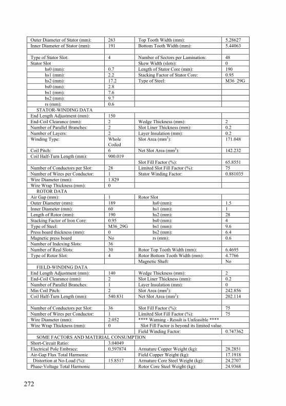
272
Outer Diameter of Stator (mm): 263 Top Tooth Width (mm): 5.28627 Inner Diameter of Stator (mm): 191 Bottom Tooth Width (mm): 5.44063 Type of Stator Slot: 4 Number of Sectors per Lamination: 48 Stator Slot Skew Width (slots): 0 hs0 (mm): 0.7 Length of Stator Core (mm): 190 hs1 (mm): 2.2 Stacking Factor of Stator Core: 0.95 hs2 (mm): 17.2 Type of Steel: M36_29G bs0 (mm): 2.8 bs1 (mm): 7.6 bs2 (mm): 9.7 rs (mm): 0.6 STATOR-WINDING DATA End Length Adjustment (mm): 150 End-Coil Clearance (mm): 2 Wedge Thickness (mm): 2 Number of Parallel Branches: 2 Slot Liner Thickness (mm): 0.2 Number of Layers: 2 Layer Insulation (mm): 0.2 Winding Type: Whole
Coiled Slot Area (mm2): 171.048
Coil Pitch: 6 Net Slot Area (mm2): 142.232 Coil Half-Turn Length (mm): 900.019 Slot Fill Factor (%): 65.8551 Number of Conductors per Slot: 28 Limited Slot Fill Factor (%): 75 Number of Wires per Conductor: 1 Stator Winding Factor: 0.881035 Wire Diameter (mm): 1.829 Wire Wrap Thickness (mm): 0 ROTOR DATA Air Gap (mm): 1 Rotor Slot Outer Diameter (mm): 189 hs0 (mm): 1.5 Inner Diameter (mm): 60 hs1 (mm): 1 Length of Rotor (mm): 190 hs2 (mm): 28 Stacking Factor of Iron Core: 0.95 bs0 (mm): 4 Type of Steel: M36_29G bs1 (mm): 9.6 Press board thickness (mm): 0 bs2 (mm): 6.4 Magnetic press board No rs (mm): 0.6 Number of Indexing Slots: 36 Number of Real Slots: 30 Rotor Top Tooth Width (mm): 6.4695 Type of Rotor Slot: 4 Rotor Bottom Tooth Width (mm): 4.7766 Magnetic Shaft: No FIELD-WINDING DATA End Length Adjustment (mm): 140 Wedge Thickness (mm): 2 End-Coil Clearance (mm): 2 Slot Liner Thickness (mm): 0.2 Number of Parallel Branches: 1 Layer Insulation (mm): 0 Min Coil Pitch: 2 Slot Area (mm2): 242.856 Coil Half-Turn Length (mm): 540.831 Net Slot Area (mm2): 202.114 Number of Conductors per Slot: 36 Slot Fill Factor (%): 75 Number of Wires per Conductor: 1 Limited Slot Fill Factor (%): 75 Wire Diameter (mm): 2.052 **** Warning - Result is Unfeasible **** Wire Wrap Thickness (mm): 0 Slot Fill Factor is beyond its limited value. Field Winding Factor: 0.747362 SOME FACTORS AND MATERIAL CONSUMPTION Short-Circuit Ratio: 3.04049 Electrical Pole Embrace: 0.597874 Armature Copper Weight (kg): 28.2851 Air-Gap Flux Total Harmonic Field Copper Weight (kg): 17.1918 Distortion at No-Load (%): 15.8517 Armature Core Steel Weight (kg): 24.2707 Phase-Voltage Total Harmonic Rotor Core Steel Weight (kg): 24.9368
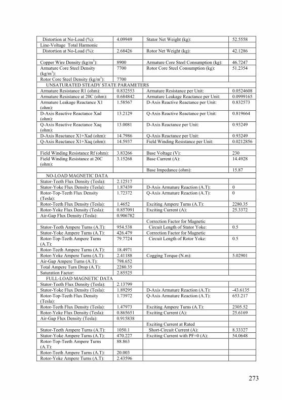
273
Distortion at No-Load (%): 4.09949 Stator Net Weight (kg): 52.5558 Line-Voltage Total Harmonic Distortion at No-Load (%): 2.68426 Rotor Net Weight (kg): 42.1286 Copper Wire Density (kg/m3): 8900 Armature Core Steel Consumption (kg): 46.7247 Armature Core Steel Density (kg/m3):
7700 Rotor Core Steel Consumption (kg): 51.2354
Rotor Core Steel Density (kg/m3): 7700 UNSATURATED STEADY STATE PARAMETERS Armature Resistance R1 (ohm): 0.832553 Armature Resistance per Unit: 0.0524608 Armature Resistance at 20C (ohm): 0.684842 Armature Leakage Reactance per Unit: 0.0999165 Armature Leakage Reactance X1 (ohm):
1.58567 D-Axis Reactive Reactance per Unit: 0.832573
D-Axis Reactive Reactance Xad (ohm):
13.2129 Q-Axis Reactive Reactance per Unit: 0.819664
Q-Axis Reactive Reactance Xaq (ohm):
13.0081 D-Axis Reactance per Unit: 0.93249
D-Axis Reactance X1+Xad (ohm): 14.7986 Q-Axis Reactance per Unit: 0.93249 Q-Axis Reactance X1+Xaq (ohm): 14.5937 Field Winding Resistance per Unit: 0.0212856 Field Winding Resistance Rf (ohm): 3.83266 Base Voltage (V): 230 Field Winding Resistance at 20C (ohm):
3.15268 Base Current (A): 14.4928
Base Impedance (ohm): 15.87 NO-LOAD MAGNETIC DATA Stator-Teeth Flux Density (Tesla): 2.12517 Stator-Yoke Flux Density (Tesla): 1.87439 D-Axis Armature Reaction (A.T): 0 Rotor-Top-Teeth Flux Density (Tesla):
1.72372 Q-Axis Armature Reaction (A.T): 0
Rotor-Teeth Flux Density (Tesla): 1.4652 Exciting Ampere Turns (A.T): 2280.35 Rotor-Yoke Flux Density (Tesla): 0.857091 Exciting Current (A): 25.3372 Air-Gap Flux Density (Tesla): 0.906782 Correction Factor for Magnetic Stator-Teeth Ampere Turns (A.T): 954.538 Circuit Length of Stator Yoke: 0.5 Stator-Yoke Ampere Turns (A.T): 426.479 Correction Factor for Magnetic Rotor-Top-Teeth Ampere Turns (A.T):
79.7724 Circuit Length of Rotor Yoke: 0.5
Rotor-Teeth Ampere Turns (A.T): 18.4971 Rotor-Yoke Ampere Turns (A.T): 2.41188 Cogging Torque (N.m): 5.02901 Air-Gap Ampere Turns (A.T): 798.652 Total Ampere Turn Drop (A.T): 2280.35 Saturation Factor: 2.85525 FULL-LOAD MAGNETIC DATA Stator-Teeth Flux Density (Tesla): 2.13799 Stator-Yoke Flux Density (Tesla): 1.89295 D-Axis Armature Reaction (A.T): -43.6135 Rotor-Top-Teeth Flux Density (Tesla):
1.73972 Q-Axis Armature Reaction (A.T): 653.217
Rotor-Teeth Flux Density (Tesla): 1.47973 Exciting Ampere Turns (A.T): 2305.52 Rotor-Yoke Flux Density (Tesla): 0.865651 Exciting Current (A): 25.6169 Air-Gap Flux Density (Tesla): 0.915838 Exciting Current at Rated Stator-Teeth Ampere Turns (A.T): 1050.1 Short-Circuit Current (A): 8.33327 Stator-Yoke Ampere Turns (A.T): 470.227 Exciting Current with PF=0 (A): 54.0648 Rotor-Top-Teeth Ampere Turns (A.T):
88.863
Rotor-Teeth Ampere Turns (A.T): 20.003 Rotor-Yoke Ampere Turns (A.T): 2.43596
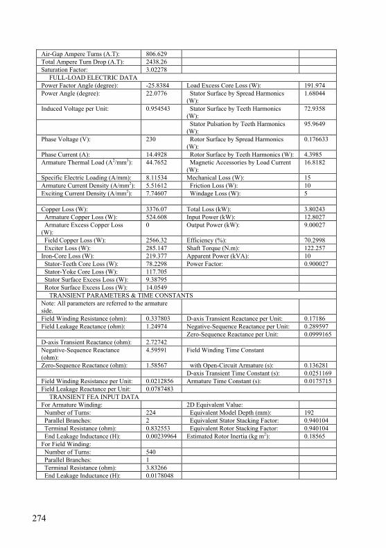
274
Air-Gap Ampere Turns (A.T): 806.629 Total Ampere Turn Drop (A.T): 2438.26 Saturation Factor: 3.02278 FULL-LOAD ELECTRIC DATA Power Factor Angle (degree): -25.8384 Load Excess Core Loss (W): 191.974 Power Angle (degree): 22.0776 Stator Surface by Spread Harmonics
(W): 1.68044
Induced Voltage per Unit: 0.954543 Stator Surface by Teeth Harmonics (W):
72.9358
Stator Pulsation by Teeth Harmonics (W):
95.9649
Phase Voltage (V): 230 Rotor Surface by Spread Harmonics (W):
0.176633
Phase Current (A): 14.4928 Rotor Surface by Teeth Harmonics (W): 4.3985 Armature Thermal Load (A2/mm3): 44.7652 Magnetic Accessories by Load Current
(W): 16.8182
Specific Electric Loading (A/mm): 8.11534 Mechanical Loss (W): 15 Armature Current Density (A/mm2): 5.51612 Friction Loss (W): 10 Exciting Current Density (A/mm2): 7.74607 Windage Loss (W): 5 Copper Loss (W): 3376.07 Total Loss (kW): 3.80243 Armature Copper Loss (W): 524.608 Input Power (kW): 12.8027 Armature Excess Copper Loss (W):
0 Output Power (kW): 9.00027
Field Copper Loss (W): 2566.32 Efficiency (%): 70.2998 Exciter Loss (W): 285.147 Shaft Torque (N.m): 122.257 Iron-Core Loss (W): 219.377 Apparent Power (kVA): 10 Stator-Teeth Core Loss (W): 78.2298 Power Factor: 0.900027 Stator-Yoke Core Loss (W): 117.705 Stator Surface Excess Loss (W): 9.38795 Rotor Surface Excess Loss (W): 14.0549 TRANSIENT PARAMETERS & TIME CONSTANTS Note: All parameters are referred to the armature side.
Field Winding Resistance (ohm): 0.337803 D-axis Transient Reactance per Unit: 0.17186 Field Leakage Reactance (ohm): 1.24974 Negative-Sequence Reactance per Unit: 0.289597 Zero-Sequence Reactance per Unit: 0.0999165 D-axis Transient Reactance (ohm): 2.72742 Negative-Sequence Reactance (ohm):
4.59591 Field Winding Time Constant
Zero-Sequence Reactance (ohm): 1.58567 with Open-Circuit Armature (s): 0.136281 D-axis Transient Time Constant (s): 0.0251169 Field Winding Resistance per Unit: 0.0212856 Armature Time Constant (s): 0.0175715 Field Leakage Reactance per Unit: 0.0787483 TRANSIENT FEA INPUT DATA For Armature Winding: 2D Equivalent Value: Number of Turns: 224 Equivalent Model Depth (mm): 192 Parallel Branches: 2 Equivalent Stator Stacking Factor: 0.940104 Terminal Resistance (ohm): 0.832553 Equivalent Rotor Stacking Factor: 0.940104 End Leakage Inductance (H): 0.00239964 Estimated Rotor Inertia (kg m2): 0.18565 For Field Winding: Number of Turns: 540 Parallel Branches: 1 Terminal Resistance (ohm): 3.83266 End Leakage Inductance (H): 0.0178048

275
Fig.B-6: Three-phase winding distribution in 48 slots stator core of synchronous machine Appendix C: Maxwell’s Equations Tree and Response
Study
Maxwell's equations represent one of the most concise ways to state the fundamentals of electricity and magnetism. From these unified equations the most of the working relationships in the field of electricity and magnetism one can be developed. These equations can be represented in integral or differential form as illustrated in the following sections. However, all the relations of Maxwell’s equations can be arranged in a tree, as shown in Fig.C-1, below [Ref.3, Chapter 5].
Fig.C-1: A tree of relations present Maxwell’s equations
Maxwell’s Equations
Gauss’s Law Electric
Differential Form
II. without Magnetic
Media
I. with Magnetic & Polarization
Wave Equation
Charge Conservation
Ampere’s Law
Integral Form, without
Magnetic Media
Faraday’s Law
Gauss’s Law Magnetic
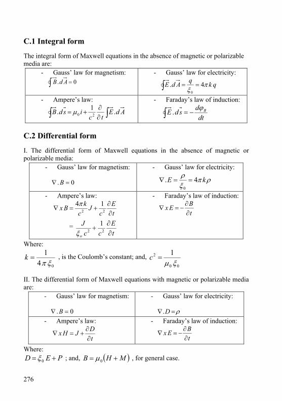
276
C.1 Integral form The integral form of Maxwell equations in the absence of magnetic or polarizable media are:
- Gauss’ law for magnetism:
∫ = 0. AdB - Gauss’ law for electricity:
qkqAdE πξ
4.0
==∫
- Ampere’s law:
∫ ∫∂∂
+= AdEtc
isdB .1. 20μ - Faraday’s law of induction:
∫ −=dt
dsdE Bϕ.
C.2 Differential form I. The differential form of Maxwell equations in the absence of magnetic or polarizable media:
- Gauss’ law for magnetism:
0. =∇ B
- Gauss’ law for electricity:
ρπξρ kE 4.
0
==∇
- Ampere’s law:
tE
cJ
ckBx
∂∂
+=∇ 22
14π
= tE
ccJ
o ∂∂
+ 221
ξ
- Faraday’s law of induction:
tBEx
∂∂
−=∇
Where:
041ξπ
=k , is the Coulomb’s constant; and, 00
2 1ξμ
=c
II. The differential form of Maxwell equations with magnetic or polarizable media are:
- Gauss’ law for magnetism:
0. =∇ B
- Gauss’ law for electricity:
ρ=∇ D. - Ampere’s law:
tDJHx
∂∂
+=∇ - Faraday’s law of induction:
tBEx
∂∂
−=∇
Where: PED += 0ξ ; and, ( )MHB += 0μ , for general case.
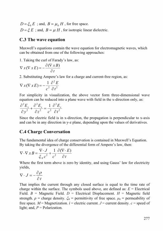
277
ED 0ξ= ; and, HB 0μ= , for free space. ED ξ= ; and, HB μ= , for isotropic linear dielectric.
C.3 The wave equation Maxwell’s equations contain the wave equation for electromagnetic waves, which can be obtained from one of the following approaches: 1. Taking the curl of Farady’s law, as:
tBxExx
∂∇∂
−=∇∇)()(
2. Substituting Ampere’s law for a charge and current-free region, as:
2
2
2
1)(tE
cExx
∂∂
−=∇∇
For simplicity in visualization, the above vector form three-dimensional wave equation can be reduced into a plane wave with field in the x-direction only, as:
2
2
22
2
2
2 1tE
czE
yE xxx
∂∂
=∂
∂+
∂∂
Since the electric field is in x-direction, the propagation is perpendicular to x-axis and can be in any direction in y-z plane, depending upon the values of derivatives. C.4 Charge Conversation The fundamental idea of charge conservation is contained in Maxwell’s Equation. By taking the divergence of the differential form of Ampere’s law, then:
tE
ccJBx
∂⋅∇∂
+⋅∇
=∇⋅∇)(1
220ξ
Where the first term above is zero by identity, and using Gauss’ law for electricity yields,
tJ
∂∂
−=⋅∇ρ
That implies the current through any closed surface is equal to the time rate of charge within the surface. The symbols used above, are defined as: E = Electrical Field. B = Magnetic Field. D = Electrical Displacement. H = Magnetic field strength. ρ = charge density. ξ0 = permittivity of free space. μ0 = permeability of free space. M = Magnetization. i = electric current. J = current density. c = speed of light; and, P = Polarization.
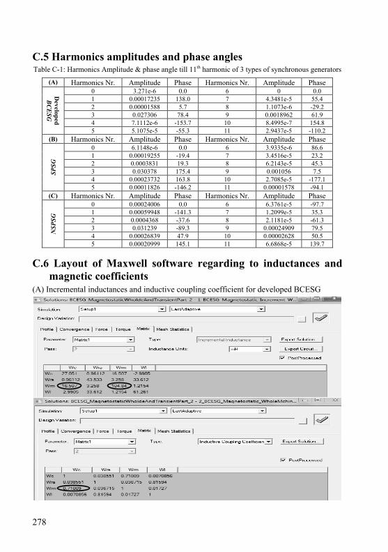
278
C.5 Harmonics amplitudes and phase angles
Table C-1: Harmonics Amplitude & phase angle till 11th harmonic of 3 types of synchronous generators
(A) Harmonics Nr. Amplitude Phase Harmonics Nr. Amplitude Phase 0 3.271e-6 0.0 6 0 0.0 1 0.00017235 138.0 7 4.3481e-5 55.4 2 0.00001588 5.7 8 1.1073e-6 -29.2 3 0.027306 78.4 9 0.0018962 61.9 4 7.1112e-6 -153.7 10 8.4995e-7 154.8
Developed B
CE
SG
5 5.1075e-5 -55.3 11 2.9437e-5 -110.2 (B) Harmonics Nr. Amplitude Phase Harmonics Nr. Amplitude Phase
0 6.1148e-6 0.0 6 3.9335e-6 86.6 1 0.00019255 -19.4 7 3.4516e-5 23.2 2 0.0003831 19.3 8 6.2143e-5 45.3 3 0.030378 175.4 9 0.001056 7.5 4 0.00023732 163.8 10 2.7085e-5 -177.1
SPSG
5 0.00011826 -146.2 11 0.00001578 -94.1 (C) Harmonics Nr. Amplitude Phase Harmonics Nr. Amplitude Phase
0 0.00024006 0.0 6 6.3761e-5 -97.7 1 0.00059948 -141.3 7 1.2099e-5 35.3 2 0.0004368 -37.6 8 2.1181e-5 -61.3 3 0.031239 -89.3 9 0.00024909 79.5 4 0.00026839 47.9 10 0.00002628 50.5 N
SPSG
5 0.00020999 145.1 11 6.6868e-5 139.7 C.6 Layout of Maxwell software regarding to inductances and
magnetic coefficients
(A) Incremental inductances and inductive coupling coefficient for developed BCESG
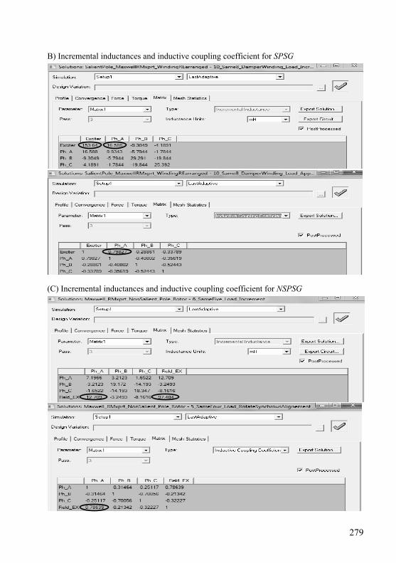
279
B) Incremental inductances and inductive coupling coefficient for SPSG
(C) Incremental inductances and inductive coupling coefficient for NSPSG
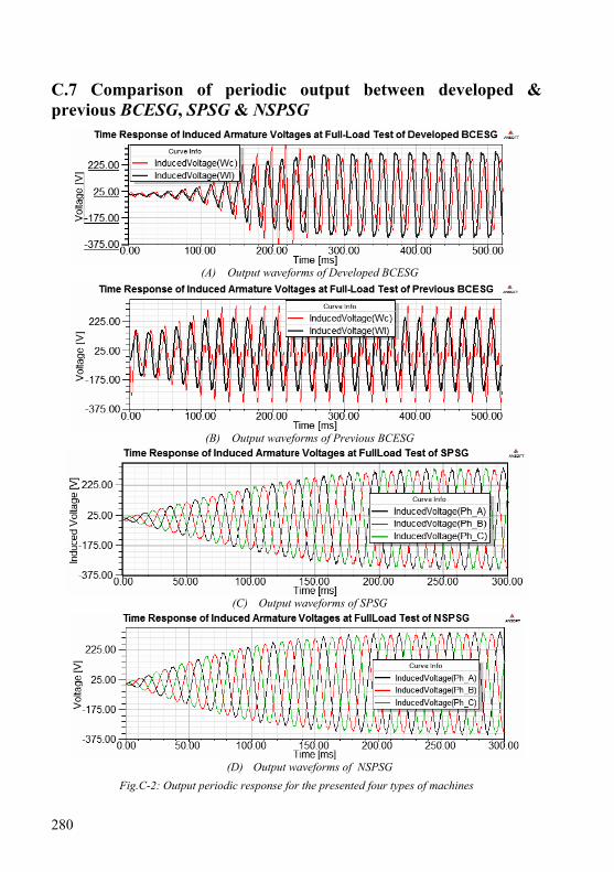
280
C.7 Comparison of periodic output between developed & previous BCESG, SPSG & NSPSG
(A) Output waveforms of Developed BCESG
(B) Output waveforms of Previous BCESG
(C) Output waveforms of SPSG
(D) Output waveforms of NSPSG
Fig.C-2: Output periodic response for the presented four types of machines

281
C.8 Magnetic force study and response plots
(A) Magnetic force in Developed BCESG
(B) Output waveforms in Previous BCESG
(C) Magnetic force in SPSG
(D) Magnetic force in NSPSG
Fig.C-3: periodic magnetic force response for the presented four types of machines
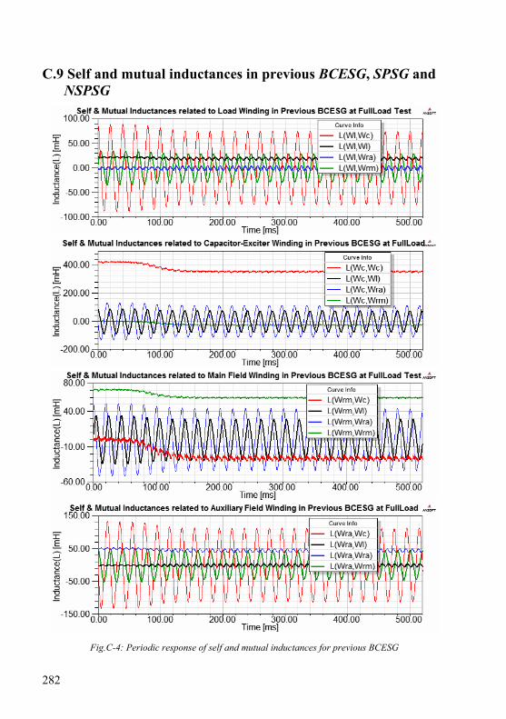
282
C.9 Self and mutual inductances in previous BCESG, SPSG and NSPSG
Fig.C-4: Periodic response of self and mutual inductances for previous BCESG

283
Fig.C-5: Periodic response of self and mutual inductances for SPSG
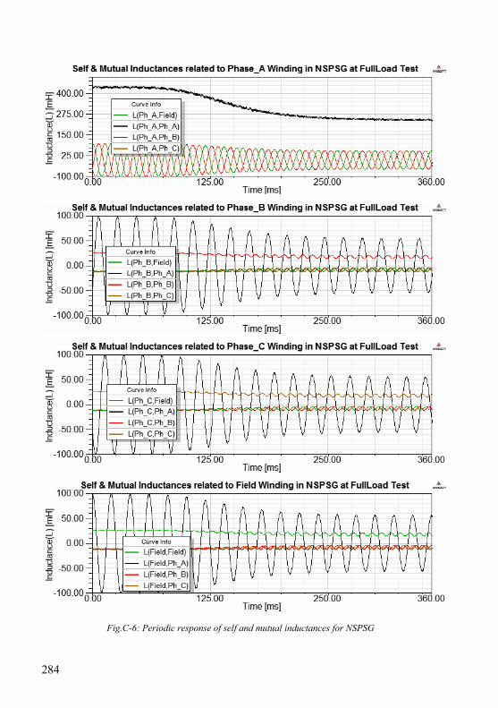
284
Fig.C-6: Periodic response of self and mutual inductances for NSPSG
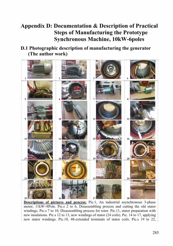
285
Appendix D: Documentation & Description of Practical Steps of Manufacturing the Prototype Synchronous Machine, 10kW-6poles
D.1 Photographic description of manufacturing the generator (The author work)
1 2 3 4
5 6 7 8
9 10 11 12
13 14 15 16
17 18 19 20
21 22 23 24
25 26 27 28
Descriptions of pictures and process: Pic.1, An industrial asynchronous 3-phase motor, 11kW×8Pole. Pic.s 2 to 6, Disassembling process and cutting the old stator windings. Pic.s 7 to 10, Disassembling process for rotor. Pic.11, stator preparation with new insulations. Pic.s 12 to 13, new windings of stator (24 coils). Pic. 14 to 17, applying new stator windings. Pic.18, 48-extended terminals of stator coils. Pic.s 19 to 22,
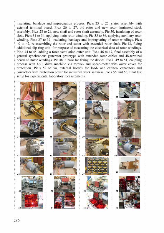
286
insulating, bandage and impregnation process. Pic.s 23 to 25, stator assembly with external terminal board. Pic.s 26 to 27, old rotor and new rotor laminated stack assembly. Pic.s 28 to 29, new shaft and rotor shaft assembly. Pic.30, insulating of rotor slots. Pic.s 31 to 34, applying main rotor winding. Pic 35 to 36, applying auxiliary rotor winding. Pic.s 37 to 39, insulating, bandage and impregnating of rotor windings. Pic.s 40 to 42, re-assembling the rotor and stator with extended rotor shaft. Pic.43, fixing additional slip-ring unit; for purpose of measuring the electrical data of rotor windings. Pic.s 44 to 45, adding a force ventilation outer unit. Pic.s 46 to 47, final assembly of a general synchronous generator prototype with extended rotor cables and 48-terminal board of stator windings. Pic.48, a base for fixing the diodes. Pic.s 49 to 51, coupling process with D.C. drive machine via torque- and speed-meter with outer cover for protection. Pic.s 52 to 54, external boards for load- and exciter- capacitors and contactors with protection cover for industrial work safeness. Pic.s 55 and 56, final test setup for experimental laboratory measurements.
29 30 31 32
33 34 35 36
37 38 39 40
41 42 43 44
45 46 47 48
49 50 51 52
53 54 55 56
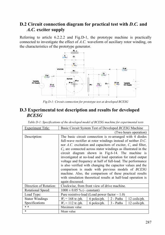
287
D.2 Circuit connection diagram for practical test with D.C. and A.C. exciter supply
Referring to article 6.2.2.2 and Fig.D-1, the prototype machine is practically connected to investigate the effect of A.C. waveform of auxiliary rotor winding, on the characteristics of the prototype generator.
C x
STATOR
W r m
ROTOR
VariableDC Supply
V r mCh1-Osc.2
I r mCh2-Osc.2
V cCh3-Osc.1
I cCh4-Osc.1
V LCh1-Osc.1
W c
W L
C LI L
Ch2-Osc.1
R L
W r a
V r aCh3-Osc.2
VariableAC Supply
I r aCh4-Osc.2
Fig.D-1: Circuit connection for prototype test at developed BCESG D.3 Experimental test description and results for developed
BCESG
Table D-1: Specifications of the developed model of BCESG machine for experimental tests
Experiment Title: Basic Circuit System Test of Developed BCESG Machine (Two hours operation)
Description: The basic circuit connection is re-arranged with 4 diodes full-wave rectifier at rotor windings instead of neither D.C. nor A.C. excitation and capacitors of exciter, Cx and filter, CL are connected across stator windings as illustrated in the circuit diagram shown in Fig.6-14. The machine is investigated at no-load and load operation for rated output voltage and frequency at half of full-load. The performance is also verified with changing the capacitor values and the comparison is made with previous models of BCESG machine. Also, the comparison of these practical results with simulation theoretical results at half-load operation is again discussed.
Direction of Rotation: Clockwise, from front view of drive machine. Rotational Speed: 1000 ± 0.05 % (~ constant) Load Type: Pure resistive-load (Load power factor ~ 1.0)
Wl = 168 tr./ph. 6 poles/ph. 2 - Paths 12 coils/ph. Stator Windings Specifications Wl = 112 tr./ph. 6 poles/ph. 3 - Paths 12 coils/ph. * * Maximum value * Mean value

288
Table D-2: Measured readings of developed BCESG by increasing the capacitor value, at constant load
IL
[A]
VL
[V]
f
[Hz]
Tr
[Nm]
ItL
[A]
Vc
[V]
Ic
* [A]
Vrm
* * [V]
Irm
* [A]
frm
[Hz]
Vra
* * [V]
Ira
* [A]
CL
[μF]
Po
[kW]
12.6 220 50.0 - 15.5 160 1.76 472 7.22 99.4 460 0.88 123.4
12.7 222 50.0 - 15.8 160 1.76 452 7.31 99.4 472 0.96 127.1
13 225 50.0 - 16.4 161 1.78 456 7.48 99.8 468 1.13 134.9
13.1 228 50.5 - 17 161 1.73 432 7.64 100.3 460 1.28 142.7
13.2 232 50.0 - 17.6 162 1.81 432 7.79 100.5 428 1.37 150.5
13.6 238 50.0 38 18.8 163 1.86 384 8.12 100.1 308 1.68 165.5 3.26
THD in Vc = 8.43 % at load value IL = 13.6 A
Cx = 195.5 μF (constant) & Speed = 1000 ± 0.05 % (~ constant)
D.4 Results of transient analysis for two seconds at half-load
state of developed BCESG
(A)
(B)
Fig.D-2 : Time response analysis for core loss and Torque of developed BCESG , at a half of full-load
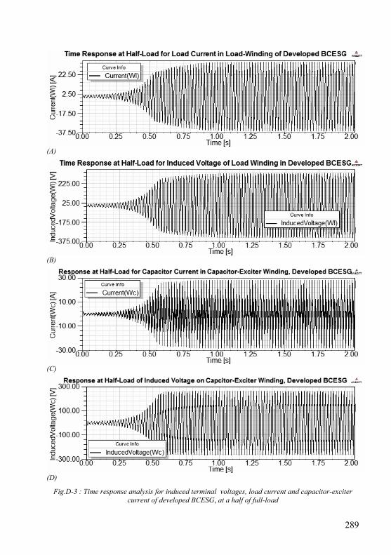
289
(A)
(B)
(C)
(D)
Fig.D-3 : Time response analysis for induced terminal voltages, load current and capacitor-exciter current of developed BCESG, at a half of full-load

290
D.5 The complete electronic circuit (LPEC) built for developed BCESG
Fig.D-4: Proposal of the Electronic Control Circuit (LPEC)

291
Bibliography
Chapter 1 1. Siegfried Heier: Windkraftanlagen - Systemauslegung, Netzintergration
und Regelung, Vieweg + Teubner, Wiesbaden 2009. 2. Gesche Krause: From turbine to wind farms - technical requirements and
spin-off products, InTech, 2011. 3. H. Li and Z. Chen: Overview of different wind generator systems and
their comparisons, IET Renew. Power Gener., 2008, vol. 2, no. 2, pp. 123–138, Institution of Engineering and Technology 2008.
4. Mohamed Ridha Khadraoui and Mohamed Elleuch: Comparison between OptiSlip and fixed speed wind energy conversion systems, IEEE 5th International Multi-Conference on Systems, Signals and Devices, 2008.
5. Hui Li, Zhe Chen and Henk Polinder: Optimization of multibrid permanent-magnet wind generator systems, IEEE Transactions on Energy Conversion, vol. 24, no. 1, March 2009.
6. Clipper Windpower Inc., at: http://www.clipperwind.com/techspecs.html, accessed February 2012.
7. A. Khosravi, A. Jalali and H. Mojallali: Robust control design for a wind turbine-induction generator unit- computer systems and applications, AICCSA '07, IEEE/ACS International Conference, May 2007.
8. Pedro Lobato, A. Cruz, J. Silva and A. J. Pires: The switched reluctance generator for wind power conversion, 9CHLIE - 9th Spanish Portuguese Congress on Electrical Engineering, Marbella, Spain, July 2005.
9. F. Jurca, C. Martis, C. Oprea and D. Fodorean: Claw-pole machine design and tests for small scale direct driven applications, International Conference on Clean Electrical Power (ICCEP), Romania, June 2011.
10. Yongchang Zhang and Jianguo Zhu: Direct torque control of cascaded brushless doubly fed induction generator for wind energy applications, IEEE International Electric Machines & Drives Conference (IEMDC), May 2011.
Chapter 2 1. K. Harada and S. Nonaka: Self-excited single-phase synchronous
generator, Japanese patent no.244444, 1958. 2. S. Nonaka and K. Kesamaru: Brushless three-phase synchronous
generator without exciter, IEE Japan, vol. 105, no. 6, pp.91-99, October 1985.
3. Likaa Fahmi A. Izzat and S. Heier: Bürstenloser Synchrongenerator und Generatoranordnung mit einem bürstenlosen Synchrongenerator,

292
Deutsches Patent DE 10 2010 060 998 A1, 06.06.2012. 4. Likaa Fahmi A. Izzat and S. Heier: Neuentwicklung von bürstenlosen,
selbsterregten und selbstgeregelten Synchrongenerator-Systemen, Beitrag von Jahresbericht-2010, pp.23, IEE/EVS-KDEE, Universität Kassel, Deutschland März 2011.
5. Likaa Fahmi A. Izzat and S. Heier: Entwicklung von bürstenlosen, selbst-erregten und -geregelten Synchrongenerators, Beitrag von Jahresbericht 2012, pp.59, IEE/EVS-KDEE, Universität Kassel, Deutschland Februar 2013.
6. A. Khosravi, A. Jalali and H. Mojallali: Robust control design for a wind turbine-induction generator unit- computer systems and applications, AICCSA '07, IEEE/ACS International Conference, May 2007.
7. Pedro Lobato, A. Cruz, J. Silva and A. J. Pires: The switched reluctance generator for wind power conversion, 9CHLIE - 9th Spanish Portuguese Congress on Electrical Engineering, Marbella, Spain, July 2005.
8. F. Jurca, C. Martis, C. Oprea and D. Fodorean: Claw-pole machine design and tests for small scale direct driven applications, International Conference on Clean Electrical Power (ICCEP), Romania, June 2011.
9. Yongchang Zhang and Jianguo Zhu: Direct torque control of cascaded brushless doubly fed induction generator for wind energy applications, IEEE International Electric Machines & Drives Conference (IEMDC), May 2011.
10. S. Nonaka, I. Muta and R. Ide: Fundamental characteristics of the brushless self-excited cylindrical-rotor type single-phase synchronous generator, Proc. Fac. Eng. Kyushu Univ., vol. 42, p.861, January 1970.
11. Steinhilber, Siegfried, Tübingen: Anordnung zur kostenlosen Erregung eines Synchrongenerators, Deutsche Patent 2258284 C3, 1977.
12. Masuda Yutaka: Capacitor-excitation type brushless self-exciting synchronous generator, Japanese Patent 56071462 A, 1981.
13. Massaki Kubo, Shizuoka, Japan: Synchronous Generator, United States Patent 4246532 A1, 1981.
14. Nonaka Sakutaro: Brushless single phase synchronous generator with AC exciter, Japanese Patent 59061456 A, 1984.
15. Ikegami Hideki: Inductor type brushless generator, Japanese Patent 61046149A, 1986.
16. Ikegami Hideki: Voltage compensation circuit for synchronous brushless multiphase generator of inductor type, Japanese Patent 61293141 A, 1986.
17. K. Inoue, H. Yamashita E. Nakamae T. Fujikawa: A brushless self-exciting three-phase synchronous generator utilizing the 5th-space harmonic component of magneto motive force through armature currents, IEEE Transaction on Energy Conversion, vol. 7, no. 3, September 1992.
18. Kantor, Jozef, Margo, HU: Synchronous-machine rotor, primary for
293
brushless self-excited single-phase synchronous generators, International Patent WO 9950951 A1, 1999.
19. S. Nonaka and M. Oomoto: A brushless cylindrical-rotor 4-pole three-phase synchronous generator without exciter, Trans. IEE of Japan, vol. 119-D, no. 5, pp. 720, 1999
20. Likaa Fahmi A. Izzat: Analysis & computer aided design of brushless single-phase synchronous generators, M.Sc. Thesis, Faculty of Electromechanical Engineering, University of Technology, Iraq 2000.
21. Carraro, Diego, Vicenza, IT: Spannungsregler für einen Wechselstromgenerator, Deutsche Patent 60123269 T2, 2007.
Chapter 3 1. T. F. Chan and Lie-Tong Yan: Performance analysis of a brushless and
exciterless AC generator, IEEE Trans. on Energy Conversion, vol. 12, no. 1, March 1997.
2. T. Fukami, T. Kondo and T. Miyamoto: Analysis of a self-regulated, self-excited, brushless three-phase synchronous generator, which includes the effect of core losses, IEE Japan, vol. 131, no. 2, 2000.
3. P. C. Krause: Analysis of Electric Machinery, McGraw-Hill Book Company, New York 1986.
4. P. S. Bimbhra: Generalized theory of electrical machines, Khanna Publishers, Delhi, 2007.
5. B. Adkins and R.G. Harley: The general theory of alternating current machines - Application to practical problems, Chapman and Hall Ltd, London 1975.
6. K. S. Krikor and Likaa Fahmi A. Izzat: A comprehensive analysis for synchronous generators with brushless excitation, Eng. & Technology, vol. 20, no. 9, Iraq 2001.
7. S. Nonaka: The brushless self-excited type single-phase synchronous generator, IEE Japan, vol. 82, pp. 627-634, April 1962.
8. S. Nonaka and I. Muta: Characteristics of brushless self-excited, single-phase synchronous generators, IEE Japan, vol. 91, no. 4, 1971.
9. F. Shibata and N. Naoe: Characteristics of brushless and exciterless, self-excited synchronous generators, Conf. Rec. of IEEE Ind. Appl. Soc. Annu. Meeting, vol. 1, pp.293-300, Seattle, WA, 1990.
10. T. Fukami, Y. Hanada and T. Miyamoto: Analysis of the self-excited three-phase synchronous generator utilizing the second space harmonic for excitation, IEE Japan, vol. 121, no. 1, 1997.
11. S. Nonaka, K. Kesamaru and K. Horita: Analysis of brushless three-phase synchronous generator without exciter, Trans. IEE Japan, vol. 112-D, no. 5, May 1992.
12. S. Nonaka and K. Kesamaru: Analysis of voltage-adjustable brushless
294
synchronous generator without exciter, IEEE Trans. on Industry Applications, vol. 25, no. 1, pp.126-132, January/February 1989.
13. S. Nonaka and K. Kesamaru: Magnetic field analysis of brushless four-pole single-phase synchronous generator without exciter, International Conference on Electrical Machines, Cambridge, pp.1177, 1990.
14. W. J. Gibbs: Electric machine analysis using matrices, Pitman, London 1962.
15. S. Nonaka and K. Kesamaru: Field circuit of brushless two-pole single-phase synchronous generator without exciter, National Conv. IEE Japan, no. 808, 1986.
16. S. Nonaka and I. Muta: Analysis of brushless self-excited cylindrical-rotor type single-phase synchronous generator, Trans. IEE Japan, vol. 92-B, no. 3, pp. 205-214, March 1972.
17. S. Nonaka and K. Kesamaru: Brushless separately excited three-phase synchronous generator without exciter, Proc. of Int. Conf. on Electrical Machines, Budapest, pp.446-449, 1982.
18. S. Nonaka, K. Kesamaru and H. Tanaka: Magnetic field analysis of brushless self-excited type single-phase synchronous generator, Report RM-83-31 of the Studying Committee on Rotating Machinery, July 1983.
19. S. Nonaka: Analysis of the self-excited salient-pole type single-phase synchronous machine, IEE Japan, vol. 81, pp. 377, March 1961.
20. S. Nonaka and I. Muta: An analytical study of the brushless self-excited type single-phase synchronous generator, IEE Japan, vol. 86, pp.1140, July 1966.
21. J. A. Edminister: Theory and problems of electric circuits, Schaum’s Outline Series, McGraw-Hill Book Company, New York, 1983.
22. Likaa Fahmi A. Izzat and K. S. Krikor: Design of brushless single phase alternator" 4th International Conference, CATAEE-2002, Amman-Jordan, March 2002.
23. S. Nonaka and K. Kesamaru: Characteristics of brushless single-phase and three-phase synchronous generator without exciter, Proc. of Int. Conf. on Electrical Machines, Lausanne, pp. 325-328, 1984.
24. S. Nonaka, K. Kesamaru and F. Fuji: Characteristics of the brushless separately-excited three-phase synchronous generator without exciter, Report RM-82-5 of the Studying Committee on Rotating Machinery, Feb. 1982.
Chapter 4 1. Siegfried Heier: Grid integration of wind energy conversion systems, John
Wiley & Sons Ltd., England 2006. 2. 1st-Product.com Inc. 1997-2012, all rights reserved: Generator TWG series
three phase brushless synchronous generator, at: http://1st-
295
product/products/745/Generator-TWG-Series-Three-Phase-Brushless-Synchronous-Generator-402338.html, Post date 15.07.2012.
3. K. M. Vishnu Murthy: Computer-aided design of electrical machines, BS Publications, Hyderabad 2008.
4. A. K. Sawhney and A. Chakrabarti: A course in electrical machine design, Dhanpat Rai & Co. (P) Ltd., Delhi 2006.
5. M. Kostenko and L. Piotrovsky: Electrical machines - Alternating current machines, Mir Publishers, Moscow 1977.
6. Acesita S. A. – Group Arcelor: Electrical steels, Grain-oriented silicon steels, Non-oriented silicon steels, at: www.acesita.com.br , ED. 1/agosto 2007.
7. Asko Parviainen: Design of axial-flux permanent-magnet low-speed machines and performance comparison between radial-flux and axial-flux machines, Ph.D. Dissertation, Lappeenranta University of Technology, Finland 2005.
8. Essam S. Hamdi: Design of small electrical machines, John Wiley & Sons Ltd., England 1994.
9. M. G. Say: The performance and design of alternating current machines, Sir Isaac Pitman & Sons, Ltd. London 1958.
10. Ion Boldea: Synchronous generators - the electrical generators handbook, Taylor & Francis Group, LLC, FL-USA, 2006.
11. Juha Pyrhönen, Tapani Jokinen and Valeria Hrabovcova: Design of rotating electrical machines, John Wiley & Sons, Ltd., UK 2008.
12. R.S. Khurmi and J.K. Gupta: Machine design, Eurasia Publishing House (PVT.) Ltd., New Delhi 1979.
13. Kais S. I. Al-Sabagh: Performance and design of single phase induction motors, M.Sc. Thesis in Electrical Engineering, College of Engineering, University of Baghdad, Iraq 1976.
14. K. S. Krikor and Likaa Fahmi A. Izzat: Design and manufacture of single phase alternator with brushless excitation, Eng. & Development, vol.4, no.2, Baghdad-Iraq, July 2000.
15. Computer aided design of industrial motors, Electrical machine design course in Bucharest, Romania submitted to State Company of Electrical Industries, Baghdad-Iraq 1980.
16. Cyril G. Veinott: Theory and design of small induction motors, McGraw-Hill Book Company Inc., New York, 1959.
17. B.L. Theraja and A.K. Theraja: A text-book of electrical technology, Nirja Construction & Development Co. (P) LTD, New Delhi, 1988.
18. D. P. Sen Gupta and J. W. Lynn: Electrical machine dynamics, the Macmillan Press Ltd, Hong Kong, 1980.
19. Documentation & online Maxwell help: Analysis approach for three-phase machines, Ansoft Maxwell & RMxprt, Version 15.0.0, SAS IP, Inc., 2011.

296
Chapter 5 1. Bruce Klimpke, Integrated Engineering Software/ Enginia Research,
Canada: A hybrid magnetic field solver using a combined finite element/ boundary element field solver, presented at Advanced Electromagnetic Modeling & CAD for Industrial Application, Alstom Research and Technology Center, Stafford, U.K. 2003.
2. Bruce Klimpke, Integrated Engineering Software/ Enginia Research, Canada: A hybrid approach to magnetic field analysis, An Advanstar Publication, U.S.A., Sensors Vol.21, No.5, May 2004.
3. Carl R. Nave: Hyper physics by the SciLinks program, a service of National Science Teachers Association, Department of physics and Astronomy, Georgia State University, U.S.A. 2012.
Chapter 7 1. Likaa Fahmi A. Izzat and S. Heier: Steuerschaltung für selbstregelnde
Kondensator-Erregte Synchrongeneratoren in einem weiten drehzahlbereit, Beitrag von Jahresbericht 2011, pp.26, IEE/EVS-KDEE, Universität Kassel, Deutschland Februar 2012.
2. C. Alexander and M. Sadiku: Fundamentals of electric circuits, 4th Edition; Ebooks for JNTU subjects Electric circuits and Network Theory and Basic Electrical Engineering and Principles of Electrical Engineering, McGraw-Hill, August, 2008.
297
Symbols and Abbreviations A a Empirical constant related to iron loss in the machine core A.C. Alternating current, A a1 Parallel current path of stator load winding
A1 Ratio between fundamental component of maximum flux density at machine core and the air-gap flux density per pole
a1c Parallel current path of stator capacitor winding a2 Number of parallel current path of rotor auxiliary winding a2s Number of parallel paths of rotor main field winding A3 Coefficient of the 3rd harmonics wave A5 Coefficient of the 5rd harmonics wave ac Specific electrical loading, A/m Ac2n Cross-sectional area of effective bare conductor of rotor auxiliary winding in
slots type-S2n, m2 Ac2s Cross sectional area of effective bare conductor of rotor main winding in slots
type-S2s, m2 ACIM Alternating current induction modifier
Ad1 , Aq1 Flux distribution coefficient for direct- and quadrate- axis component of armature reaction, respectively
AFPM Axial flux permanent magnetic ar Effective turns ratio between two stator windings, load and capacitor-exciter
windings. As1 Total area of the stator slot without insulation, m2 As2n Surface area of the 1st type of rotor slots (slot type-S2n), m2 As2s Surface area of the 2st type of rotor slots (slot type-S2s), m2 AT Magneto-motive force, A ATc Magneto motive force of armature phase winding per pole, A ATcd Direct-axis of Magneto motive force of armature phase winding per pole, A ATf Rotor main magneto motive force per pole, A ATf0 Magneto-motive force per pole in air-gap at no-load operation ATfa Magneto motive force of rotor auxiliary winding, A ATg Magneto-motive force at minimum length of air-gap, A ATh1 , ATh2 Magneto-motive force at yoke of stator and rotor per pole, respectively; A ATl Magneto motive force of armature reaction of load winding per phase ATt0 Total magneto-motive force in the machine active parts (air-gap, yoke and core),
A ATt1 , ATt2 Magneto-motive force at stator and rotor teeth, respectively; A AVBM Auxiliary voltage building up means az1 Effective cross-section area of the conductor for stator winding, m2 az1c Effective cross-section of wire-conductor of stator capacitor-exciter-winding, m2 az1l Effective cross sectional area of wire-conductor of stator load-winding, m2 B

298
B Magnetic flux density, Tesla Bav Specific magnetic loading, Tesla BCESG Brushless capacitor-exciter synchronous generator BDFIG Brushless double feed induction generator BEM Boundary Element Method Bg Maximum air-gap flux density per pole, Tesla or Wb/m2 Bh1 Flux density of stator yoke, Wb/m2 or Tesla Bh2 Flux density of rotor yoke, Wb/m2 or Tesla Bm Maximum flux density in the machine core, Wb/m2 Bm1 Fundamental component of maximum flux density at machine core, Wb/m2 BSESG Brushless self excited synchronous generator Bt1 Maximum flux density at stator teeth, Wb/m2 Bt2 Maximum flux density at teeth between rotor slots type-S2n , Wb/m2 C C Capacitor value, μF C0 Capacitor-exciter value at resonance frequency, μF C1 , C3 , C5 Capacitor-exciter value at resonance condition for the first (fundamental), third
and fifth harmonics waveform component, respectively; μF C1,C2 Values of exciter capacitors at fundamental waveforms, μF CAD Computer aided design Co Machine output coefficient, proportional to machine rated torque per unit
volume, Wb.A/m3
cp1 Average length from outer sides of two adjacent coil sections of rotor field winding, m
cp2 Average length from inner sides of two adjacent coil sections of rotor field winding, m
CRGO Cold rolled grain-oriented steel D D.C. Direct current, A D1 Inner diameter of the stator, mm D1-D4 Rectifier Semiconductor diodes’ values D2 Rotor outer diameter, m dc1 Effective conductor diameter of stator coils, mm dc2 Effective diameter of bare conductor of rotor windings, m dc2n Effective diameter of bare conductor of rotor auxiliary winding, m dc2s Diameter of effective bare conductor of rotor main winding in slots type-S2s, m DD Direct drive DFIG Double feed induction generator Do Stator outer diameter, m do2n Diameter of circular slots of 1st type at non-salient part of rotor core, m dsh Rotor inner diameter or the shaft diameter, m E
ec Capacitor induced electromotive force across terminals of stator capacitor-exciter winding at load operation, V
Ec Induced electromotive force at stator capacitor winding, V ec0 Capacitor induced voltage at no-load operation, V
299
Ec1 Maximum value of capacitor voltage for fundamental harmonic wave, V Ec10 Maximum value of capacitor voltage at no-load for fundamental wave, V EESG Electrically excited synchronous generator
el Output induced voltage across terminals of stator load winding at load operation, V
el0 Induced output (load) electromotive force at no load operation, V
El1 Maximum induced electromotive force at stator load winding at fundamental harmonic wave, V
El10 Maximum output voltage at fundamental point no-load operation, V EMF Electromotive force, V emfd ,or; EMFrm
Induced electromotive force of double frequency at direct-axis main rotor field winding, V
emfq ,or; EMFra
Induced electromotive force of double frequency at quadrate-axis auxiliary rotor winding, V
EMFral Induced electromotive force related to rotor auxiliary winding and stator load winding, V
EMFrml Induced electromotive force related to rotor main winding and stator load winding, V
F f Electrical frequency, Hz f1 Frequency of rated output voltage and current in stator winding, Hz f2 Frequency of induced voltage and current in rotor winding, Hz
Fac Pulsating stationary single-phase magneto-motive force related to armature reaction of stator capacitor winding, A
Fal Pulsating stationary single-phase magneto-motive force related to armature reaction of stator load winding, A
FEA Finite Element Analysis FEM, 2D/ 3D Finite Element Method, two dimensions/ three dimensions
Fra ,or; Frq Summation of magnetic force components at quadrate-axis of rotor at each 180°E of rotation, related to rotor auxiliary winding, A
Frad0 Magnetic force at rotor direct-axis produced by the induced current in rotor auxiliary winding at instant of rotation equal to stationary 0°E, A
Frad90 Magnetic force at rotor direct-axis produced by the induced current in rotor auxiliary winding at instant of rotation equal to stationary 90°E, A
Fraq0 Magnetic force at rotor quadrate-axis produced by the induced current in rotor auxiliary rotor winding at instant of rotation equal to stationary 0°E, A
Fraq90 Magnetic force at rotor quadrate-axis produced by the induced current in rotor auxiliary winding at instant of rotation equal to stationary 90°E, A
Frm ,or; Frd Summation of magnetic force components at direct-axis of rotor at each 180°E of rotation, relating to rotor main winding, A
Frmd0 Magnetic force at rotor direct-axis produced by the induced current in rotor main winding at instant of rotation equal to 0°E
Frmd90 Magnetic force at rotor direct-axis produced by the induced current in rotor main winding at instant of rotation equal to 90°E.
G G2 Total weight of rotor steel core and copper windings (neglecting insulations), kg H H Magnetic field intensity, A/m h1 Height of the stator yoke, m
300
h2 Summation of minimum height of rotor yoke and rotor slot height type-S2s, m h2n Maximum height of rotor core, m h2s Minimum height of rotor yoke, m h2ss Height of the rotor slot type-S2s, m Hh1 , Hh2 Magnetic field strength at stator and rotor yoke, respectively; A/m ho2n Height of the slot-opening of 1st type at non-salient part of rotor core, m hp1 Height of insulation in the rotor slot of salient-pole type, m
hp2 Height of copper coil section of main rotor field winding in the rotor slot of salient-pole type, m
hrn Depth of rotor slot of 1st type at non-salient part of rotor core, m hrs Depth of rotor slot type-S2s , m hs Height of the stator slot, m hs1 Distance between the two bases of standard trapezoidal slot, m Ht1 , Ht2 Field strength at stator and rotor teeth, respectively; A/m ht2n Rotor-tooth height (or pole-shoe height), m I
I1, I2 Two values of instruction signals from output of control device (Low power electronic circuit)
Ic Maximum value of induced phase current in the stator capacitor-exciter winding, A
ic Instantaneous value of induced alternating phase current in stator capacitor-exciter winding, A
ic1 Fundamental (first harmonic) value of instantaneous phase current in stator capacitor-exciter winding, A
Ic1 Maximum fundamental phase current in stator capacitor winding, A Ic1d Armature current component causing the direct axis MMF of armature reaction,
A IGBT Insulated-gate bipolar transistor Il Maximum value of generator load current, A il Instantaneous value of alternating load current in the stator load winding, A Il1 Fundamental component of load phase current, A Im Magnetization current, A iR Instantaneous value of load current in the pure resistive load of the generator, A Ira Maximum value of current in rotor auxiliary winding, A ira Instantaneous value of alternating induced current in rotor auxiliary winding, A Irm Maximum value of induced current in rotor main winding, A irm Instantaneous value of induced current in rotor main winding, A Irm0 The main field current at no-load status, A Irm1 , Irm2 Induced current components, full-wave and half-wave in rotor main winding,
respectively; A ITBG Inductor type brushless generator Iz1 Conductor current in effective conductor of stator winding, A J J1 , J2 Current density in effective conductors of stator and rotor windings,
respectively; A/mm2 K k Steinmetz coefficient

301
K1 , K2 Correction factor of stator and rotor yoke magneto-motive force, respectively K1T1 First switch of first contactor K1T2 First switch of second contactor K2T2 Second switch of second contactor K3 , K5 Reactance ratio coefficient related to third and fifth harmonics at resonance
condition, respectively Kad Factor of direct-axis armature reaction KC Carter Coefficient Kc1 Chording factor for stator windings Kc2n Chording factor of rotor auxiliary winding Kd1 Distribution factor of stator windings Kd2n Distribution factor of rotor auxiliary winding KE Reduction factor related to voltage-drop, due to resistance and leakage reactance ke Factor depends on number of layers of winding Kf Form factor of the magnetic waveform, which is related to saturation factor Kf exc Form factor of the excitation field
Kfd , Kfq Form factor of the direct- and quadrate- axis component of armature reaction, respectively
Kfe Stacking factor of electrical steel material Kg Gap contraction factor Kh , Ke Coefficient of hysteresis and eddy-current loss, respectively Ks1 Slot fullness factor of bare conductors in bare slot area of stator slot Ks2s , Ks2n Slot fullness factor of bare conductors in bare slot area of rotor slot type-S2s and
type-S2n , respectively Ksd Magnetic saturation factor Kwl , Kwc Winding factor for stator load- and capacitor-exciter- winding, respectively Kwra Winding factor of rotor auxiliary winding L L Stack length of steel core (assuming equal packet length for rotor and stator), m L0 Zero-sequence component of Inductance (inductance value at resonance
frequency), H L1 , L2 Stack length of stator and rotor core, respectively; m l2n Number of layers of rotor auxiliary winding la2 Mean length of one turn of rotor auxiliary winding, m Lb Inner distance between the two ball-bearings’ sides, m Lc0 Zero-sequence Inductance of capacitor windings, H L'c0 Transient value of zero-sequence inductance related to armature capacitor-
exciter winding, H lc1 Mean length of one turn of stator capacitor-exciter-winding, m Lc2 Negative-sequence component of Inductance, H LD , LQ Stationary direct- and quadrate- axis inductance, respectively; H L'D , L'Q Transient value of stationary direct- and quadrate- axis inductances,
respectively; H Lf Self inductance of rotor field winding, H lg Air-gap length opposite to the center of the pole, m lg1 Length of air-gap along uniformly part of pole face (minimum length of air-
302
gap), m lg2 Larger length of air-gap, facing the rotor quadrate-axis part, m L'l0 Transient value of zero-sequence inductance related to armature load winding ,
H Ll0 , Lc0 Zero-sequence inductance related to armature load and capacitor-exciter
windings, H ll1 Mean length of one whole turn of stator load-winding, m L'l2 Transient value of negative-sequence inductance related to armature load
winding , H Ll2 , Lc2 Negative-sequence inductance related to armature load and capacitor-exciter
windings, respectively; H lm2 Average length of a coil in rotor main winding, m LPEC Low-power electronic circuit Lrm , Lra Total self inductances of rotor main- and auxiliary- winding, respectively; H M m ,or ml Number of phases of stator armature (load-) winding Mcf Mutual inductance between stator capacitor-exciter winding and rotor field
winding, H Mcra ,or Mrac Mutual inductance between stator capacitor-exciter winding and rotor auxiliary
winding, H Mcrm ,or Mrmc Mutual inductance between stator capacitor-exciter winding and rotor main
winding, H Mlra ,or Mral Mutual inductance between stator load winding and rotor auxiliary winding, H Mlrm ,or Mrml Mutual inductance between stator load winding and rotor main winding, H MMF Magneto-motive force, A N n.c. Normally-closed contact of the contactor switch n.o. Normally-opened contact of the contactor switch Nc2n Number of effective conductor of rotor auxiliary winding per slot of 1st type at
non-salient part of rotor core (slots type- S2n) Nc2s Number of effective conductors of rotor main winding per slot of 2st type at
salient part of rotor core (slots type-S2s) NGRO Non-oriented steel sheet np Peripheral speed, m/s ns Synchronous rotational speed, r.p.s. ns Synchronous speed, rpm P p Number of poles of the machine P1 Machine input power (related to input rotating torque) , W P1.5 Specific iron loss at flux density 1.5 Wb/m2 P2 Machine output power, W Padd Additional power loss, W Parc Pole-arc length, m Pcu Total copper losses in the generator, W Pe Specific Eddy current loss, W/kg Pfe Total iron loss, W Pfw Friction and windage power loss, W

303
Ph Specific Hysteresis loss, W/kg Pi Total specific iron loss, W/kg PM Permanent magnetic PMSG Permanent magnetic synchronous generator Ppuls Pulsation power loss, W Pt Total power loss in the machine, W PWc Copper losses in stator capacitor-exciter winding, W PWl Copper losses in stator load winding, W PWra Copper losses in rotor auxiliary winding, W PWrm , PWra Copper losses in rotor main and auxiliary winding, respectively; W Q q1 Number of slots per pole per phase for stator winding q2n Number of rotor slots type-S2n per pole per number of phase of rotor auxiliary
winding R R Pure resistive load, Ω rc Internal resistance of capacitor stator winding, Ω RFPM Radial flux permanent magnetic rl Internal resistance of load winding, Ω rl1 , rc1 Internal resistance of the stator load- and capacitor-exciter- winding,
respectively; Ω rm2 , ra2 Internal resistance per phase of the rotor main- and auxiliary- winding,
respectively; Ω
rrm , rra Internal resistance per phase of rotor main- and auxiliary- winding, respectively; Ω
S S Machine apparent output power, VA S1 Number of stator slots S2n Number of 1st type of rotor slots (slots of non-salient-pole type), embedded
punching at non-salient part of rotor poles S2s Number of 2nd type of rotor slots (slots of salient-pole type), embedded
punching at salient part of rotor poles SCIG Squirrel cage induction generator SCR Short-circuit ratio SNSP Salient and non-salient pole T t Instantaneous time, s T1 Input rotating torque, Nm T1, T2 Two values of mechanical contactors TFPM Transversal-flux permanent magnetic Tl1 , Tc1 Number of turns per phase for stator load- and capacitor-exciter- winding,
respectively Tra Number of turns per phase per path of rotor auxiliary winding Trap Number of turns per pole per phase of rotor auxiliary winding Trm Number of turns per path of rotor main winding Trmp Number of turns per one pole of rotor main field winding
304
V Vc Maximum terminal voltage across stator capacitor-exciter winding, V vc Instantaneous value of terminal voltage across stator capacitor-exciter winding,
V Vl Maximum terminal voltage across stator load winding, V vl Instantaneous fundamental voltage at terminals of stator load winding (generator
output voltage or load voltage), V Vra Built up voltage across terminals of rotor auxiliary winding, V Vrm Built up voltage across terminals of rotor main winding, V W W2s Smaller base length of the trapezoidal rotor slot type-S2s, m W2ss Larger base length of the trapezoidal rotor slot type-S2s, m Wl , Wc Stator load- and capacitor-exciter winding, respectively wo2n Width of the slot-opening of 1st type, at non-salient part of rotor core, m Wp Width of pole body, m WRIG Wound rotor induction generator Wrm , Wra Rotor main- and auxiliary- winding, respectively Wrs Average gap length between two adjacent sides of rotor poles, m Ws1 Average width of stator slot, m Ws11 Larger base of standard trapezoidal slot shape, m Wt1 Average width of stator tooth, m Wt2n Average active width between two adjacent sides of slots type-S2n , m X
Xad ,or Xmd Mutual inductance between the armature winding and rotor field winding at direct axis, p.u.
Xaq Mutual inductance between the armature winding and rotor field winding at quadrate axis, p.u.
XC Capacitance reactance, per-unit Xc0 Zero sequence of the armature reactance, per-unit X'c0 Transient zero-sequence armature reactance, per-unit X''c0 Sub-transient reactance related to zero sequence armature reaction, per-unit XC1 , XC3 , XC5 Capacitive reactance value at resonance condition for the first (fundamental),
third and fifth harmonics waveform component, respectively; per-unit Xc2 Negative-sequence armature reactance, per-unit Xcf Inductive mutual reactance between armature and field windings, per-unit Xcf
2/Xf Saturation coefficient represents as ratio of square mutual reactance over self reactance, per-unit
XD , XQ Direct- and quadrate- axis synchronous reactance, respectively; per-unit X'D , X'Q Transient value of direct- and quadrate- axis synchronous reactance,
respectively; per-unit Xf Inductive self reactance of the rotor main field winding, per-unit xm Magnetization reactance, Ω Xm Magnetization reactance, p.u. Xr a Inductive reactance of rotor auxiliary winding, p.u. Xσ Leakage reactance, p.u. xσ c , xσ l Leakage reactance of stator capacitor-exciter and load- winding, Ω

305
Xσ c , Xσ l Leakage reactance of stator capacitor-exciter and load- winding, respectively; p.u.
xσ f Leakage inductive reactance at salient-pole part of rotor, Ω Xσ f Leakage inductive reactance at salient-pole part of rotor, p.u. Xσ f , Xσ n Leakage reactance of rotor main and auxiliary field winding, p.u. xσ f , xσ n Leakage reactance of rotor main and auxiliary field winding, Ω xσ l , xσ c Armature leakage reactance at stator load- and capacitor-exciter- winding, Ω Y y2n Slot pitch of rotor slots type-S2n in terms of angle, ° M; or distance length, m ys1 Stator slot pitch in term of mechanical angle, °M; or distance length, m Z Z1 Total number of effective conductors Zs1 Number of effective conductors per stator slot α Pole arc coefficient αp Pole arc angle, °E αδ Magnetic leakage factor, which is related to saturation factor γi Iron density, kg/m3 γi1 , γi2 Iron density of stator and rotor core, kg/m3 δ Angle between axis of stator load winding and the rotor direct axis, at time, t =
0; °E δ1 Load angle, °E η Machine efficiency, % θ Angular displacement between stationary load winding axis and rotor main field
axis, °E λσ Magnetic permeance λσ e Permeance factor of end-connections λσ f Permeance at salient-pole part of rotor λσ s Slot permeance factor λσ g Air-gap permeance factor λσ l Armature leakage permeance μ Magnetic permeability, H/m μ0 Permeability of free space ρ Resistivity of the electrical steel material, Ω.m ρcu Resistivity of copper conductor, Ω.m ρd Reduction factor for direct axis armature magneto-motive force τ1 , τ1l Stator pole pitch in term of number of slots and distance length in m,
respectively τ2 Peripheral length of rotor pole-pitch, m τ2n Pole pitch in terms of rotor slots number of type-S2n τc1 Stator coil pitch in term of number of slots τc2n Coil pitch in terms of rotor slots number of type-S2n τh1 , τh2 Magnetic pole pitch length at stator and rotor yoke, respectively; m τrat Ratio of pole-arc length to pole-pitch length ϕ Maximum air-gap flux per pole, Wb

306
ϕf Resultant value of field flux per rotor pole, Wb φl0 The effective value of flux linkage to stator load winding at no-load condition,
Wb ψ1 Summation of power-factor angle and load angle ω0 Angular frequency at resonance operation, rad Ιc1 , Ιc3 , Ιc5 Maximum value of current in stator capacitor-exciter winding at first
(fundamental), third and fifth harmonics, respectively; A
ϕfd , ϕfq Flux linkage with rotor main- and auxiliary- winding at rotor direct- and quadrate- axis, respectively; Wb
ϕfd1 , ϕfd2 Flux linkage components due to full-wave and half-wave current components in rotor main winding, respectively; Wb
ϕl , ϕc Flux linkage with stator load- and capacitor-exciter- windings, respectively; Wb
ω Angular velocity, rad
fϕ& Vector quantity of the resultant rotor field flux, Wb
1lI& Vector quantity of the fundamental component of load current in stator load winding, A
1cI& Vector quantity of the fundamental component of capacitor-exciter current in stator capacitor-exciter winding, A
1φ Power factor angle, °E
A Vector quantity of Magnetic potential, Wb/m
J Vector quantity of Current density, A/m2
H Vector quantity of field intensity, A/m
B Vector quantity of flux density, Wb/m2
ϑ1 Time phase-shift angle between quadrate-axis component of field voltage and load voltage, °E
ϑc Time Phase shift angle between current and voltage in stator capacitor-exciter winding, °E
ϑc1 , ϑc3 , ϑc5 Time phase shift angle between current & voltage in capacitor-exciter winding at first (fundamental), third and fifth harmonics, respectively, °E
ϑl1 Time phase-shift angle between generating load voltage and load current for fundamental waveform, °E
°E Electrical degrees µ0 Permittivity of free space 3G; 1G Three stage; one stage
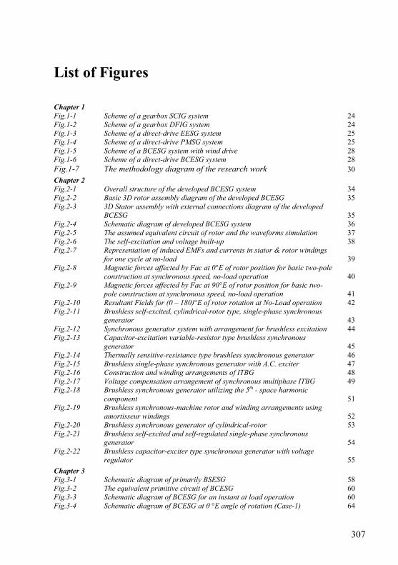
307
List of Figures Chapter 1 Fig.1-1 Scheme of a gearbox SCIG system 24 Fig.1-2 Scheme of a gearbox DFIG system 24 Fig.1-3 Scheme of a direct-drive EESG system 25 Fig.1-4 Scheme of a direct-drive PMSG system 25 Fig.1-5 Scheme of a BCESG system with wind drive 28 Fig.1-6 Scheme of a direct-drive BCESG system 28 Fig.1-7 The methodology diagram of the research work 30
Chapter 2 Fig.2-1 Overall structure of the developed BCESG system 34 Fig.2-2 Basic 3D rotor assembly diagram of the developed BCESG 35 Fig.2-3 3D Stator assembly with external connections diagram of the developed
BCESG 35 Fig.2-4 Schematic diagram of developed BCESG system 36 Fig.2-5 The assumed equivalent circuit of rotor and the waveforms simulation 37 Fig.2-6 The self-excitation and voltage built-up 38 Fig.2-7 Representation of induced EMFs and currents in stator & rotor windings
for one cycle at no-load 39 Fig.2-8 Magnetic forces affected by Fac at 0°E of rotor position for basic two-pole
construction at synchronous speed, no-load operation 40 Fig.2-9 Magnetic forces affected by Fac at 90°E of rotor position for basic two-
pole construction at synchronous speed, no-load operation 41 Fig.2-10 Resultant Fields for (0 – 180)°E of rotor rotation at No-Load operation 42 Fig.2-11 Brushless self-excited, cylindrical-rotor type, single-phase synchronous
generator 43 Fig.2-12 Synchronous generator system with arrangement for brushless excitation 44 Fig.2-13 Capacitor-excitation variable-resistor type brushless synchronous
generator 45 Fig.2-14 Thermally sensitive-resistance type brushless synchronous generator 46 Fig.2-15 Brushless single-phase synchronous generator with A.C. exciter 47 Fig.2-16 Construction and winding arrangements of ITBG 48 Fig.2-17 Voltage compensation arrangement of synchronous multiphase ITBG 49 Fig.2-18 Brushless synchronous generator utilizing the 5th - space harmonic
component 51 Fig.2-19 Brushless synchronous-machine rotor and winding arrangements using
amortisseur windings 52 Fig.2-20 Brushless synchronous generator of cylindrical-rotor 53 Fig.2-21 Brushless self-excited and self-regulated single-phase synchronous
generator 54 Fig.2-22 Brushless capacitor-exciter type synchronous generator with voltage
regulator 55
Chapter 3 Fig.3-1 Schematic diagram of primarily BSESG 58 Fig.3-2 The equivalent primitive circuit of BCESG 60 Fig.3-3 Schematic diagram of BCESG for an instant at load operation 60 Fig.3-4 Schematic diagram of BCESG at θ °E angle of rotation (Case-1) 64
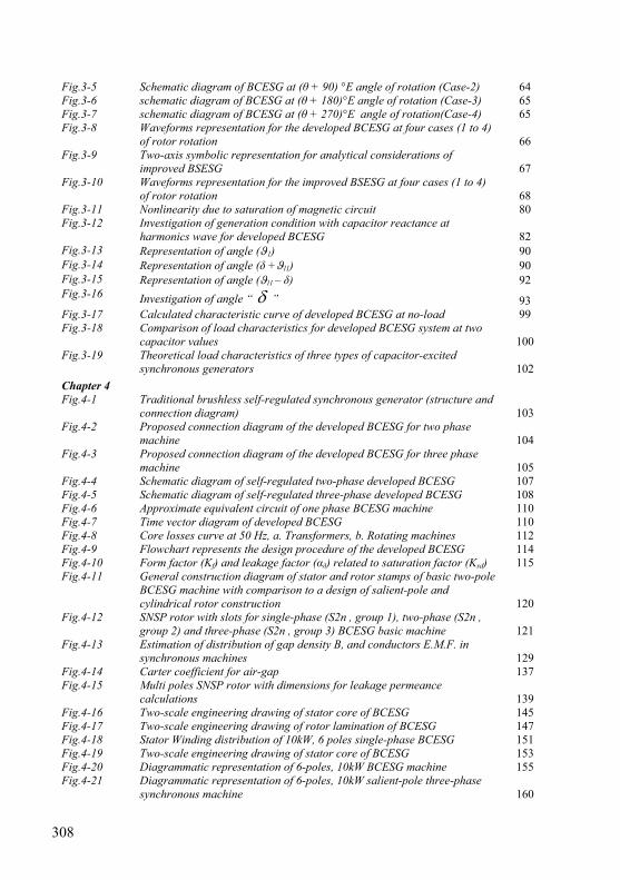
308
Fig.3-5 Schematic diagram of BCESG at (θ + 90) °E angle of rotation (Case-2) 64 Fig.3-6 schematic diagram of BCESG at (θ + 180)°E angle of rotation (Case-3) 65 Fig.3-7 schematic diagram of BCESG at (θ + 270)°E angle of rotation(Case-4) 65 Fig.3-8 Waveforms representation for the developed BCESG at four cases (1 to 4)
of rotor rotation 66 Fig.3-9 Two-axis symbolic representation for analytical considerations of
improved BSESG 67 Fig.3-10 Waveforms representation for the improved BSESG at four cases (1 to 4)
of rotor rotation 68 Fig.3-11 Nonlinearity due to saturation of magnetic circuit 80 Fig.3-12 Investigation of generation condition with capacitor reactance at
harmonics wave for developed BCESG 82 Fig.3-13 Representation of angle (ϑ1) 90 Fig.3-14 Representation of angle (δ +ϑl1) 90 Fig.3-15 Representation of angle (ϑl1 – δ) 92 Fig.3-16 Investigation of angle “ δ ” 93 Fig.3-17 Calculated characteristic curve of developed BCESG at no-load 99 Fig.3-18 Comparison of load characteristics for developed BCESG system at two
capacitor values 100 Fig.3-19 Theoretical load characteristics of three types of capacitor-excited
synchronous generators 102
Chapter 4 Fig.4-1 Traditional brushless self-regulated synchronous generator (structure and
connection diagram) 103 Fig.4-2 Proposed connection diagram of the developed BCESG for two phase
machine 104 Fig.4-3 Proposed connection diagram of the developed BCESG for three phase
machine 105 Fig.4-4 Schematic diagram of self-regulated two-phase developed BCESG 107 Fig.4-5 Schematic diagram of self-regulated three-phase developed BCESG 108 Fig.4-6 Approximate equivalent circuit of one phase BCESG machine 110 Fig.4-7 Time vector diagram of developed BCESG 110 Fig.4-8 Core losses curve at 50 Hz, a. Transformers, b. Rotating machines 112 Fig.4-9 Flowchart represents the design procedure of the developed BCESG 114 Fig.4-10 Form factor (Kf) and leakage factor (αδ) related to saturation factor (Ksd) 115 Fig.4-11 General construction diagram of stator and rotor stamps of basic two-pole
BCESG machine with comparison to a design of salient-pole and cylindrical rotor construction 120
Fig.4-12 SNSP rotor with slots for single-phase (S2n , group 1), two-phase (S2n , group 2) and three-phase (S2n , group 3) BCESG basic machine 121
Fig.4-13 Estimation of distribution of gap density B, and conductors E.M.F. in synchronous machines 129
Fig.4-14 Carter coefficient for air-gap 137 Fig.4-15 Multi poles SNSP rotor with dimensions for leakage permeance
calculations 139 Fig.4-16 Two-scale engineering drawing of stator core of BCESG 145 Fig.4-17 Two-scale engineering drawing of rotor lamination of BCESG 147 Fig.4-18 Stator Winding distribution of 10kW, 6 poles single-phase BCESG 151 Fig.4-19 Two-scale engineering drawing of stator core of BCESG 153 Fig.4-20 Diagrammatic representation of 6-poles, 10kW BCESG machine 155 Fig.4-21 Diagrammatic representation of 6-poles, 10kW salient-pole three-phase
synchronous machine 160
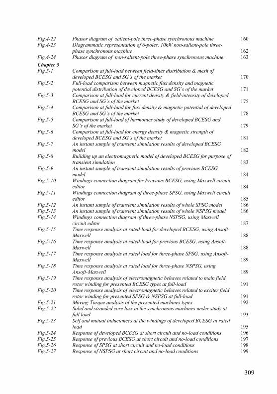
309
Fig.4-22 Phasor diagram of salient-pole three-phase synchronous machine 160 Fig.4-23 Diagrammatic representation of 6-poles, 10kW non-salient-pole three-
phase synchronous machine 162 Fig.4-24 Phasor diagram of non-salient-pole three-phase synchronous machine 163
Chapter 5 Fig.5-1 Comparison at full-load between field-lines distribution & mesh of
developed BCESG and SG’s of the market 170 Fig.5-2 Full-load comparison between magnetic flux density and magnetic
potential distribution of developed BCESG and SG’s of the market 171 Fig.5-3 Comparison at full-load for current density & field-intensity of developed
BCESG and SG’s of the market 175 Fig.5-4 Comparison at full-load for flux density & magnetic potential of developed
BCESG and SG’s of the market 178 Fig.5-5 Comparison at full-load of harmonics study of developed BCESG and
SG’s of the market 179 Fig.5-6 Comparison at full-load for energy density & magnetic strength of
developed BCESG and SG’s of the market 181 Fig.5-7 An instant sample of transient simulation results of developed BCESG
model 182 Fig.5-8 Building up an electromagnetic model of developed BCESG for purpose of
transient simulation 183 Fig.5-9 An instant sample of transient simulation results of previous BCESG
model 184 Fig.5-10 Windings connection diagram for Previous BCESG, using Maxwell circuit
editor 184 Fig.5-11 Windings connection diagram of three-phase SPSG, using Maxwell circuit
editor 185 Fig.5-12 An instant sample of transient simulation results of whole SPSG model 186 Fig.5-13 An instant sample of transient simulation results of whole NSPSG model 186 Fig.5-14 Windings connection diagram of three-phase NSPSG, using Maxwell
circuit editor 187 Fig.5-15 Time response analysis at rated-load for developed BCESG, using Ansoft-
Maxwell 188 Fig.5-16 Time response analysis at rated-load for previous BCESG, using Ansoft-
Maxwell 188 Fig.5-17 Time response analysis at rated load for three-phase SPSG, using Ansoft-
Maxwell 189 Fig.5-18 Time response analysis at rated load for three-phase NSPSG, using
Ansoft-Maxwell 189 Fig.5-19 Time response analysis of electromagnetic behaves related to main field
rotor winding for presented BCESG types at full-load 191 Fig.5-20 Time response analysis of electromagnetic behaves related to exciter field
rotor winding for presented SPSG & NSPSG at full-load 191 Fig.5-21 Moving Torque analysis of the presented machines types 192 Fig.5-22 Solid and stranded core loss in the synchronous machines under study at
full load 193 Fig.5-23 Self and mutual inductances at the windings of developed BCESG at rated
load 195 Fig.5-24 Response of developed BCESG at short circuit and no-load conditions 196 Fig.5-25 Response of previous BCESG at short circuit and no-load conditions 197 Fig.5-26 Response of SPSG at short circuit and no-load conditions 198 Fig.5-27 Response of NSPSG at short circuit and no-load conditions 199

310
Fig.5-28 Response analysis at rated load for rotor auxiliary winding in three types of machines 201
Chapter 6 Fig.6-1 The old industrial and the new prototype of synchronous generator 204 Fig.6-2 Distribution and connection of stator windings for 10kW, 6 poles two-
phase BCESG 205 Fig.6-3 Informal distribution and connection of stator windings for 10kW, 6 poles
three-phase BCESG 206 Fig.6-4 Schematic diagram of general circuit and system setup for practical tests
of prototype machine 207 Fig.6-5 Experimental test with D.C. exciter to investigate the waveforms of rotor
and stator circuits at no-load 208 Fig.6-6 Total harmonics distortion at no-load D.C. exciter of prototype machine 209 Fig.6-7 Prototype synchronous machine characteristics at D.C. exciter, no-load
operation 209 Fig.6-8 Measured results of waveforms plot of the prototype machine with D.C.
exciter and filter-capacitor 210 Fig.6-9 Total harmonics distortion of prototype machine at no-load D.C. exciter
with capacitor-filter 211 Fig.6-10 Output voltages waveforms of prototype machine at no-load D.C. exciter
with capacitor-filter 212 Fig.6-11 Induced voltages at load winding, auxiliary stator winding and rotor main
winding vs. load current 213 Fig.6-12 Drive torque, capacitor current and main rotor current vs. load current 214 Fig.6-13 The circuit diagram and measurement displays of prototype at load
operation with D.C. and A.C. exciter 214 Fig.6-14 The basic practical connection diagram of developed BCESG prototype at
no-load/ load operation 215 Fig.6-15 Induced terminal voltages of generator windings vs. load current, for
developed BCESG model 217 Fig.6-16 Torque and induced currents in the generator windings vs. load current,
for developed BCESG model 217 Fig.6-17 Induced voltages, output frequency and currents for stator and rotor of
developed BCESG model 218 Fig.6-18 Output power and harmonics of output voltage of developed BCESG
model 218 Fig.6-19 Effect of capacitor changes on the output load voltage in developed
BCESG model 219 Fig.6-20 Output waveforms and power of developed BCESG model 220 Fig.6-21 Harmonic of load output voltage and waveforms of rotor circuit for
developed BCESG model 220 Fig.6-22 Induced voltages, output frequency and currents for stator and rotor of
developed BCESG at half-load 221 Fig.6-23 Output power and harmonics of output voltage of developed BCESG at
half-load 221 Fig.6-24 A measured plot of temperature rise at half-load operation for developed
BCESG 222 Fig.6-25 Waveforms analysis of output terminal voltages and rotor flux linkages at
steady status of half-load test 222 Fig.6-26 Waveforms analysis of induced currents in stator windings at steady status
of half-load test 223 Fig.6-27 Transient response for flux linkages of rotor windings of developed 223
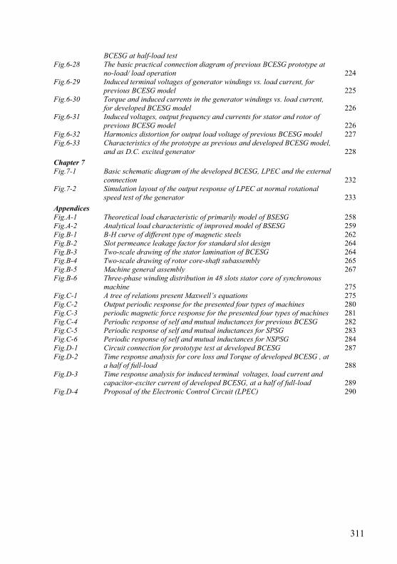
311
BCESG at half-load test Fig.6-28 The basic practical connection diagram of previous BCESG prototype at
no-load/ load operation 224 Fig.6-29 Induced terminal voltages of generator windings vs. load current, for
previous BCESG model 225 Fig.6-30 Torque and induced currents in the generator windings vs. load current,
for developed BCESG model 226 Fig.6-31 Induced voltages, output frequency and currents for stator and rotor of
previous BCESG model 226 Fig.6-32 Harmonics distortion for output load voltage of previous BCESG model 227 Fig.6-33 Characteristics of the prototype as previous and developed BCESG model,
and as D.C. excited generator 228
Chapter 7 Fig.7-1 Basic schematic diagram of the developed BCESG, LPEC and the external
connection 232 Fig.7-2 Simulation layout of the output response of LPEC at normal rotational
speed test of the generator 233
Appendices Fig.A-1 Theoretical load characteristic of primarily model of BSESG 258 Fig.A-2 Analytical load characteristic of improved model of BSESG 259 Fig.B-1 B-H curve of different type of magnetic steels 262 Fig.B-2 Slot permeance leakage factor for standard slot design 264 Fig.B-3 Two-scale drawing of the stator lamination of BCESG 264 Fig.B-4 Two-scale drawing of rotor core-shaft subassembly 265 Fig.B-5 Machine general assembly 267 Fig.B-6 Three-phase winding distribution in 48 slots stator core of synchronous
machine 275 Fig.C-1 A tree of relations present Maxwell’s equations 275 Fig.C-2 Output periodic response for the presented four types of machines 280 Fig.C-3 periodic magnetic force response for the presented four types of machines 281 Fig.C-4 Periodic response of self and mutual inductances for previous BCESG 282 Fig.C-5 Periodic response of self and mutual inductances for SPSG 283 Fig.C-6 Periodic response of self and mutual inductances for NSPSG 284 Fig.D-1 Circuit connection for prototype test at developed BCESG 287 Fig.D-2 Time response analysis for core loss and Torque of developed BCESG , at
a half of full-load 288 Fig.D-3 Time response analysis for induced terminal voltages, load current and
capacitor-exciter current of developed BCESG, at a half of full-load 289 Fig.D-4 Proposal of the Electronic Control Circuit (LPEC) 290
312
List of Tables Table 4-1 Recommended values of specific loadings for 3-phase, 50 Hz synchronous
machines 116 Table 4-2 Results from theoretical design calculations of 10kW, 6 poles developed
BCESG machine 155 Table 4-3 Magnetic and rated load design data of 10kW, 6 poles (salient-pole)
synchronous generator 161 Table 4-4 Magnetic and rated load design data of 10kW, 6 poles (non-salient-pole)
synchronous generator 163 Table 6-1 Experimental results at no-load with D.C. exciter operation of prototype
machine 208 Table 6-2 Experimental results of prototype machine at no-load, D.C. exciter operation
with capacitor-filter 211 Table 6-3 Experimental results of prototype machine at no-load with capacitors across
stator windings 211 Table 6-4 Experimental results of prototype machine at load test with constant
capacitors values and D.C. exciter 213 Table 6-5 Measuring data of prototype at load operation with both D.C. and A.C.
exciter 215 Table 6-6 Measurements’ readings of developed BCESG at load operation 216 Table 6-7 Different measurements of developed BCESG till approximately half of rated-
load 220 Table 6-8 Measurements’ readings of previous BCESG at load operation 225 Table B-1 Properties of common conducting materials 260 Table B-2 Comparison of properties of insulating materials 260 Table B-3 Types and specifications of insulating materials used in electrical machines 261 Table B-4 Properties of some soft magnetic materials, the core losses are given at 50
Hz, 1.5 Wb/m2 262 Table B-5 International standard specifications of electrical steel materials 262 Table B-6 Advantages and disadvantages due to higher specific magnetic loading 263 Table B-7 Advantages and disadvantages due to higher specific electrical loading 263 Table B-8 Standard frame size and dimensions according to IEC specifications 265 Table B-9 Data Sheet of 10kW, 6 poles (salient-pole) synchronous generator 268 Table B-10 Data Sheet of 10kW, 6 poles (non-salient-pole) synchronous generator 271 Table C-1 Harmonics Amplitude & phase angle till 17th harmonic of 3 types of
synchronous generators 278 Table D-1 Specifications of the developed model of BCESG machine for experimental
tests 287 Table D-2 Measured readings of developed BCESG by increasing the capacitor value,
at constant load 288
ISBN 978-3-86219-018-8
In this work, a developed model of brushless synchronous generator of wound rotor type is designed, analyzed by FEM, practically applied and investigated. A comparison of results with conventional machines is also performed. The presented machine can be applied for multi-pole wind/ hydro generators or double-poles diesel-engine generators. It is self-excited by residual magnetism and a connected capacitor. It is also self-regulated by making use of fluctuations at load or limited speed changes. The generated voltage may last at extended speed range by arranging a generating system with variable capacitance. By eliminating the permanent magnets or advanced manufacturing technology of rotor poles; and without using extra rotating/ external DC exciters, an efficient excitation field and an output of flat self-compensated compound characteristic are obtained. More, the feature of damper windings is determined.
Concerning the fact of environmental diminishing of elements in materials of permanent magnets and D.C. Battery, the presented novel machine is hence a good alternative and more economic from generators, exist in the market. Beside, it is safer and highly recommended for power stability when connected to the grid.
4
Likaa Fahmi Ahmed Izzat
Development of Brushless Self-excited and Self-regulated Synchronous Generating System for Wind and Hydro Generators
4
Lika
a Fa
hmi A
hmed
Izz
at
Elektrische Energiesysteme
Dev
elop
men
t of
Bru
shle
ss S
elf-e
xcit
ed a
nd S
elf-r
egul
ated
Syn
chro
nous
Gen
erat
ing
Sys
tem
for
Win
d an
d H
ydro
Gen
erat
ors