linear encoders for numerically controlled … encoders for numerically controlled machine tools...
TRANSCRIPT
June 2017
Linear EncodersFor Numerically Controlled Machine Tools
2
Further information is available on the Internet at www.heidenhain.de as well as upon request.
Brochures:• Exposed Linear Encoders• Angle Encoders with Integral Bearing• Angle encoders without integral bearing• Rotary Encoders• HEIDENHAIN Subsequent Electronics• HEIDENHAIN Controls• Measuring Devices For Machine Tool
Inspection and Acceptance Testing
Technical information brochures:• Interfaces of HEIDENHAIN Encoders• Accuracy of Feed Axes• Safety-Related Position Measuring
Systems• EnDat 2.2—Bidirectional Interface for
Position Encoders• Encoders for Direct Drives
This brochure supersedes all previous editions, which thereby become invalid.
The basis for ordering from HEIDENHAIN is always the brochure edition valid when the order is made.
Standards (ISO, EN, etc.) apply only where explicitly stated in the brochure.
Further
information:
Comprehensive descriptions of all available interfaces as well as general electrical information are included in the Interfaces of HEIDENHAIN Encoders brochure.
Overview
Linear encoders 4
Selection guide 6
Technical features and mounting information
Measuring principles Measuring standard 8
Absolute measuring method 8
Incremental measuring method 9
Photoelectric scanning principle 10
Measuring accuracy 12
Mechanical design types and mounting guidelines 14
General mechanical information 18
Functional safety 20
Specifi cations
Linear encoders Series or model
For absolute position measurement LC 400 series 22
LC 100 series 26
For absolute position measurement over large measuring lengths
LC 200 series 30
For incremental linear measurement with very high repeatability
LF 485 32
LF 185 34
For incremental linear measurement LS 400 series 36
LS 100 series 38
For incremental linear measurement over large measuring lengths
LB 382—single-section 40
LB 382—multi-section 42
Electrical connection
Incremental signals 1 VPP 44
TTL 45
Position values EnDat 46
Fanuc, Mitsubishi, Siemens 47
Cables and connecting elements 49
Diagnostic and testing equipment 58
Contents
4
Linear encoders for numerically controlled machine tools
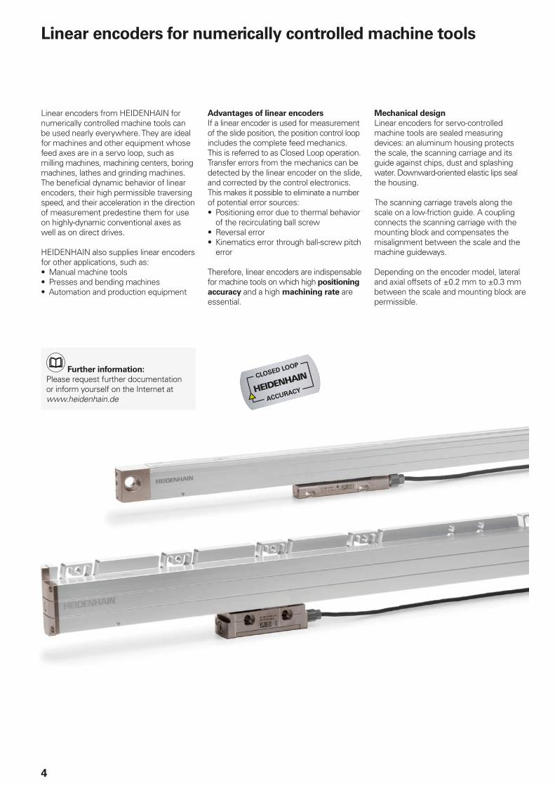
Linear encoders from HEIDENHAIN for numerically controlled machine tools can be used nearly everywhere. They are ideal for machines and other equipment whose feed axes are in a servo loop, such as milling machines, machining centers, boring machines, lathes and grinding machines. The benefi cial dynamic behavior of linear encoders, their high permissible traversing speed, and their acceleration in the direction of measurement predestine them for use on highly-dynamic conventional axes as well as on direct drives.
HEIDENHAIN also supplies linear encoders for other applications, such as:• Manual machine tools• Presses and bending machines• Automation and production equipment
Advantages of linear encoders
If a linear encoder is used for measurement of the slide position, the position control loop includes the complete feed mechanics. This is referred to as Closed Loop operation. Transfer errors from the mechanics can be detected by the linear encoder on the slide, and corrected by the control electronics. This makes it possible to eliminate a number of potential error sources:• Positioning error due to thermal behavior
of the recirculating ball screw• Reversal error• Kinematics error through ball-screw pitch
error
Therefore, linear encoders are indispensable for machine tools on which high positioning
accuracy and a high machining rate are essential.
Mechanical design
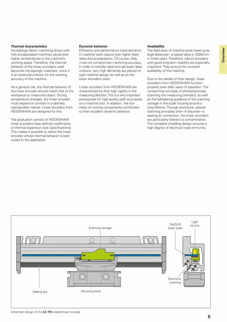
Linear encoders for servo-controlled machine tools are sealed measuring devices: an aluminum housing protects the scale, the scanning carriage and its guide against chips, dust and splashing water. Downward-oriented elastic lips seal the housing.
The scanning carriage travels along the scale on a low-friction guide. A coupling connects the scanning carriage with the mounting block and compensates the misalignment between the scale and the machine guideways.
Depending on the encoder model, lateral and axial offsets of ±0.2 mm to ±0.3 mm between the scale and mounting block are permissible.
Further information:
Please request further documentation or inform yourself on the Internet at www.heidenhain.de
5
Scanning carriage
Mounting blockSealing lips
Electronic scanning
DIADUR linear scale
Light source
Schematic design of the LC 115 sealed linear encoder
Thermal characteristics
Increasingly faster machining times with fully encapsulated machines cause ever higher temperatures in the machine’s working space. Therefore, the thermal behavior of the linear encoders used becomes increasingly important, since it is an essential criterion for the working accuracy of the machine.
As a general rule, the thermal behavior of the linear encoder should match that of the workpiece or measured object. During temperature changes, the linear encoder must expand or contract in a defi ned, reproducible manner. Linear encoders from HEIDENHAIN are designed for this.
The graduation carriers of HEIDENHAIN linear encoders have defi ned coeffi cients of thermal expansion (see Specifi cations). This makes it possible to select the linear encoder whose thermal behavior is best suited to the application.
Dynamic behavior
Effi ciency and performance improvements in machine tools require ever higher feed rates and accelerations. Of course, they must not compromise machining accuracy. In order to transfer rapid and yet exact feed motions, very high demands are placed on rigid machine design as well as on the linear encoders used.
Linear encoders from HEIDENHAIN are characterized by their high rigidity in the measuring direction. This is a very important prerequisite for high-quality path accuracies on a machine tool. In addition, the low mass of moving components contributes to their excellent dynamic behavior.
Availability
The feed axes of machine tools travel quite large distances—a typical value is 10 000 km in three years. Therefore, robust encoders with good long-term stability are especially important: They ensure the constant availability of the machine.
Due to the details of their design, linear encoders from HEIDENHAIN function properly even after years of operation. The contact-free principle of photoelectrically scanning the measuring standard, as well as the ball-bearing guidance of the scanning carriage in the scale housing ensure a long lifetime. Through enclosure, special scanning principles and—if required—a sealing air connection, the linear encoders are particularly tolerant to contamination. The complete shielding design ensures a high degree of electrical noise immunity.
Overv
iew
6
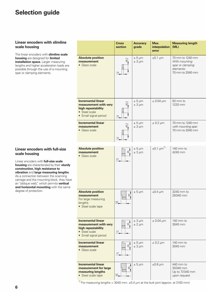
Cross
section
Accuracy
grade
Max.
interpolation
error
Measuring length
(ML)
Absolute position
measurement
• Glass scale
± 5 µm± 3 µm
±0.1 µm 70 mm to 1240 mmWith mounting spar or clamping elements:70 mm to 2040 mm
Incremental linear
measurement with very
high repeatability
• Steel scale• Small signal period
± 5 µm± 3 µm
± 0.04 µm 50 mm to1220 mm
Incremental linear
measurement
• Glass scale
± 5 µm± 3 µm
± 0.2 µm 70 mm to 1240 mmwith mounting spar:70 mm to 2040 mm
Absolute position
measurement
• Glass scale
± 5 µm± 3 µm
±0.1 µm1) 140 mm to4240 mm
Absolute position
measurement
For large measuring lengths• Steel scale tape
± 5 µm ±0.4 µm 3240 mm to28 040 mm
Incremental linear
measurement with very
high repeatability
• Steel scale• Small signal period
± 3 µm± 2 µm
± 0.04 µm 140 mm to3040 mm
Incremental linear
measurement
• Glass scale
± 5 µm± 3 µm
± 0.2 µm 140 mm to3040 mm
Incremental linear
measurement for large
measuring lengths
• Steel scale tape
± 5 µm ±0.8 µm 440 mm to30 040 mmUp to 72 040 mmupon request
1) For measuring lengths 3040 mm: ±0.4 µm at the butt joint (approx. at 3100 mm)
Selection guide
Linear encoders with slimline
scale housing
The linear encoders with slimline scale
housing are designed for limited
installation space. Larger measuring lengths and higher acceleration loads are possible through the use of a mounting spar or clamping elements.
Linear encoders with full-size
scale housing
Linear encoders with full-size scale
housing are characterized by their sturdy
construction, high resistance to
vibration and large measuring lengths. As a connection between the scanning carriage and the mounting block, they have an “oblique web,” which permits vertical
and horizontal mounting with the same degree of protection.
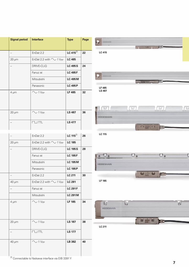
LF 485
LS 487
LC 415
LF 185
LC 115
LC 211
7
Signal period Interface Type Page
– EnDat 2.2 LC 4152)
22
20 µm EnDat 2.2 with 1 VPP LC 485
– DRIVE-CLiQ LC 495 S 24
Fanuc i LC 495 F
Mitsubishi LC 495 M
Panasonic LC 495 P
4 µm 1 VPP LF 485 32
20 µm 1 VPP LS 487 36
– TTL LS 477
– EnDat 2.2 LC 1152)
26
20 µm EnDat 2.2 with 1 VPP LC 185
– DRIVE-CLiQ LC 195 S 28
Fanuc i LC 195 F
Mitsubishi LC 195 M
Panasonic LC 195 P
– EnDat 2.2 LC 211 30
40 µm EnDat 2.2 with 1 VPP LC 281
– Fanuc i LC 291 F
Mitsubishi LC 291 M
4 µm 1VPP LF 185 34
20 µm 1 VPP LS 187 38
– TTL LS 177
40 µm 1VPP LB 382 40
2) Connectable to Yaskawa interface via EIB 3391 Y

8
Absolute measuring method
With the absolute measuring method, the position value is available from the encoder immediately upon switch-on and can be called at any time by the subsequent electronics. There is no need to move the axes to fi nd the reference position. The absolute position information is read from
the scale graduation, which is formed from a serial absolute code structure. A separate incremental track is interpolated for the position value and at the same time is used to generate an optional incremental signal.
Representation of an absolute code structure with an additional incremental track (LC 485 as example)
Graduations of absolute linear encoders
Measuring principles
Measuring standard
HEIDENHAIN encoders with optical scanning incorporate measuring standards of periodic structures known as graduations.
These graduations are applied to a carrier substrate of glass or steel. The scale substrate for large measuring lengths is a steel tape.
HEIDENHAIN manufactures the precision graduations in specially developed, photolithographic processes.• AURODUR: matte-etched lines on gold-
plated steel tape with typical graduation period of 40 µm
• METALLUR: contamination-tolerant graduation of metal lines on gold, with typical graduation period of 20 µm
• DIADUR: extremely robust chromium lines on glass (typical graduation period of 20 µm) or three-dimensional chromium structures (typical graduation period of 8 µm) on glass
• SUPRADUR phase grating: optically three dimensional, planar structure; particularly tolerant to contamination; typical graduation period of 8 µm and fi ner
• OPTODUR phase grating: optically three dimensional, planar structure with particularly high refl ectance, typical graduation period of 2 µm and fi ner
Along with these very fi ne grating periods, these processes permit a high defi nition and homogeneity of the line edges. Together with the photoelectric scanning method, this high edge defi nition is a precondition for the high quality of the output signals.
The master graduations are manufactured by HEIDENHAIN on custom-built high-precision dividing engines.
9
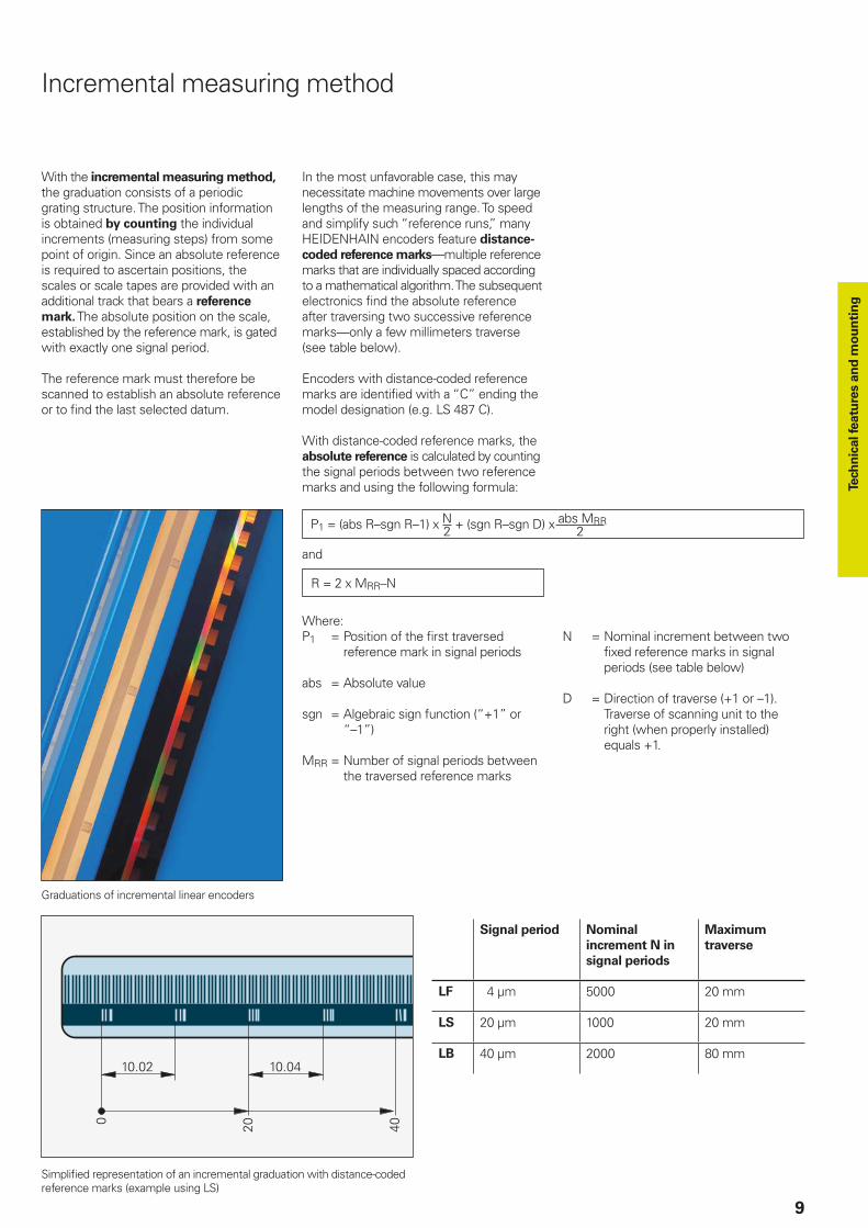
Incremental measuring method
With the incremental measuring method, the graduation consists of a periodic grating structure. The position information is obtained by counting the individual increments (measuring steps) from some point of origin. Since an absolute reference is required to ascertain positions, the scales or scale tapes are provided with an additional track that bears a reference
mark. The absolute position on the scale, established by the reference mark, is gated with exactly one signal period.
The reference mark must therefore be scanned to establish an absolute reference or to fi nd the last selected datum.
In the most unfavorable case, this may necessitate machine movements over large lengths of the measuring range. To speed and simplify such “reference runs,” many HEIDENHAIN encoders feature distance-
coded reference marks—multiple reference marks that are individually spaced according to a mathematical algorithm. The subsequent electronics fi nd the absolute reference after traversing two successive reference marks—only a few millimeters traverse (see table below).
Encoders with distance-coded reference marks are identifi ed with a “C” ending the model designation (e.g. LS 487 C).
With distance-coded reference marks, the absolute reference is calculated by counting the signal periods between two reference marks and using the following formula:
and
P1 = (abs R–sgn R–1) x N + (sgn R–sgn D) x abs MRR2 2
R = 2 x MRR–N
Where:P1 = Position of the fi rst traversed
reference mark in signal periods
abs = Absolute value
sgn = Algebraic sign function (“+1” or “–1”)
MRR = Number of signal periods between the traversed reference marks
N = Nominal increment between two fi xed reference marks in signal periods (see table below)
D = Direction of traverse (+1 or –1). Traverse of scanning unit to the right (when properly installed) equals +1.
Graduations of incremental linear encoders
Simplifi ed representation of an incremental graduation with distance-coded reference marks (example using LS)
Signal period Nominal
increment N in
signal periods
Maximum
traverse
LF 4 µm 5000 20 mm
LS 20 µm 1000 20 mm
LB 40 µm 2000 80 mm
Tech
nic
al fe
atu
res a
nd
mo
un
tin
g
10
Photoelectric scanning
Most HEIDENHAIN encoders operate using the principle of photoelectric scanning. Photoelectric scanning of a measuring standard is contact-free, and as such, free of wear. This method detects even very fi ne lines, no more than a few micrometers wide, and generates output signals with very small signal periods.
The fi ner the grating period of a measuring standard is, the greater the effect of diffraction on photoelectric scanning. HEIDENHAIN linear encoders use two scanning principles:
• The imaging scanning principle for grating periods from 20 µm and 40 µm
• The for very fi ne graduations with grating periods of, for example, 8 µm.
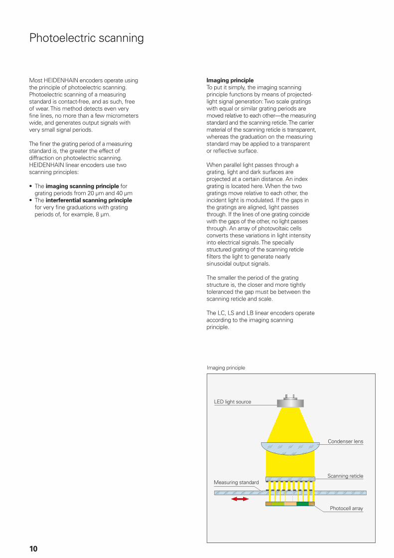
Imaging principle
To put it simply, the imaging scanning principle functions by means of projected-light signal generation: Two scale gratings with equal or similar grating periods are moved relative to each other—the measuring standard and the scanning reticle. The carrier material of the scanning reticle is transparent, whereas the graduation on the measuring standard may be applied to a transparent or refl ective surface.
When parallel light passes through a grating, light and dark surfaces are projected at a certain distance. An index grating is located here. When the two gratings move relative to each other, the incident light is modulated. If the gaps in the gratings are aligned, light passes through. If the lines of one grating coincide with the gaps of the other, no light passes through. An array of photovoltaic cells converts these variations in light intensity into electrical signals. The specially structured grating of the scanning reticle fi lters the light to generate nearly sinusoidal output signals.
The smaller the period of the grating structure is, the closer and more tightly toleranced the gap must be between the scanning reticle and scale.
The LC, LS and LB linear encoders operate according to the imaging scanning principle.
Imaging principle
LED light source
Measuring standard
Condenser lens
Scanning reticle
Photocell array
11
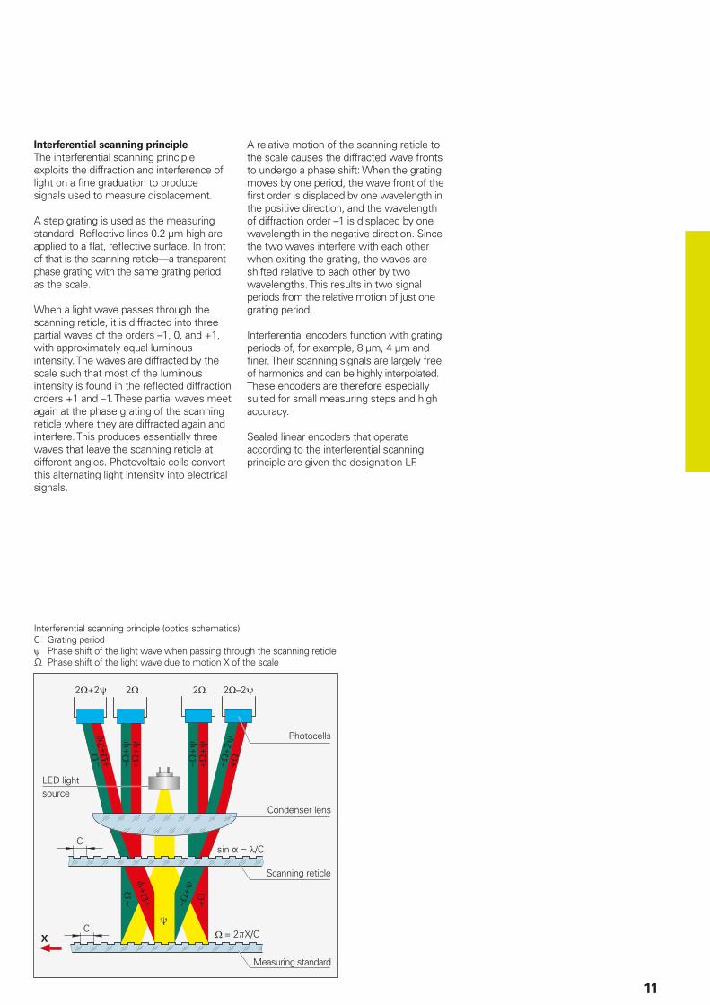
Interferential scanning principle
The interferential scanning principle exploits the diffraction and interference of light on a fi ne graduation to produce signals used to measure displacement.
A step grating is used as the measuring standard: Refl ective lines 0.2 µm high are applied to a fl at, refl ective surface. In front of that is the scanning reticle—a transparent phase grating with the same grating period as the scale.
When a light wave passes through the scanning reticle, it is diffracted into three partial waves of the orders –1, 0, and +1, with approximately equal luminous intensity. The waves are diffracted by the scale such that most of the luminous intensity is found in the refl ected diffraction orders +1 and –1. These partial waves meet again at the phase grating of the scanning reticle where they are diffracted again and interfere. This produces essentially three waves that leave the scanning reticle at different angles. Photovoltaic cells convert this alternating light intensity into electrical signals.
A relative motion of the scanning reticle to the scale causes the diffracted wave fronts to undergo a phase shift: When the grating moves by one period, the wave front of the fi rst order is displaced by one wavelength in the positive direction, and the wavelength of diffraction order –1 is displaced by one wavelength in the negative direction. Since the two waves interfere with each other when exiting the grating, the waves are shifted relative to each other by two wavelengths. This results in two signal periods from the relative motion of just one grating period.
Interferential encoders function with grating periods of, for example, 8 µm, 4 µm and fi ner. Their scanning signals are largely free of harmonics and can be highly interpolated. These encoders are therefore especially suited for small measuring steps and high accuracy.
Sealed linear encoders that operate according to the interferential scanning principle are given the designation LF.
LED light source
Measuring standard
Condenser lens
Scanning reticle
Photocells
Interferential scanning principle (optics schematics)C Grating period Phase shift of the light wave when passing through the scanning reticle Phase shift of the light wave due to motion X of the scale
12
The accuracy of linear measurement is mainly determined by:• the quality of the scale grating• the quality of the scanning process• the quality of the signal processing
electronics• the error from the scanning unit
guideway to the scale
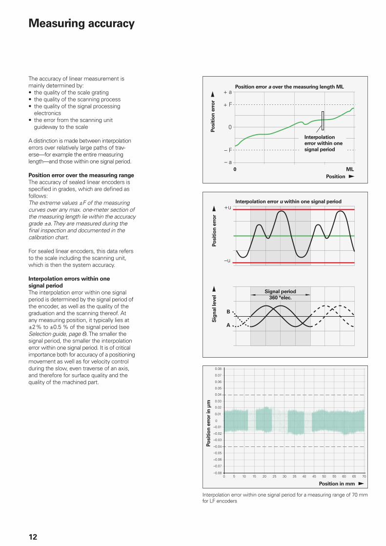
A distinction is made between interpolation errors over relatively large paths of trav-erse—for example the entire measuring length—and those within one signal period.
Position error over the measuring range
The accuracy of sealed linear encoders is specifi ed in grades, which are defi ned as follows:The extreme values ±F of the measuring curves over any max. one-meter section of the measuring length lie within the accuracy grade ±a. They are measured during the fi nal inspection and documented in the calibration chart.
For sealed linear encoders, this data refers to the scale including the scanning unit, which is then the system accuracy.
Interpolation errors within one
signal period
The interpolation error within one signal period is determined by the signal period of the encoder, as well as the quality of the graduation and the scanning thereof. At any measuring position, it typically lies at ±2 % to ±0.5 % of the signal period (see Selection guide, page 6). The smaller the signal period, the smaller the interpolation error within one signal period. It is of critical importance both for accuracy of a positioning movement as well as for velocity control during the slow, even traverse of an axis, and therefore for surface quality and the quality of the machined part.
Position error a over the measuring length ML
Interpolation
error within one
signal period
Interpolation error u within one signal period
Signal period
360 °elec.
Measuring accuracy
Po
sit
ion
err
or
Position
Po
sit
ion
err
or
Sig
nal le
vel
Po
sit
ion
err
or
in µ
m
Position in mm
Interpolation error within one signal period for a measuring range of 70 mm for LF encoders
13
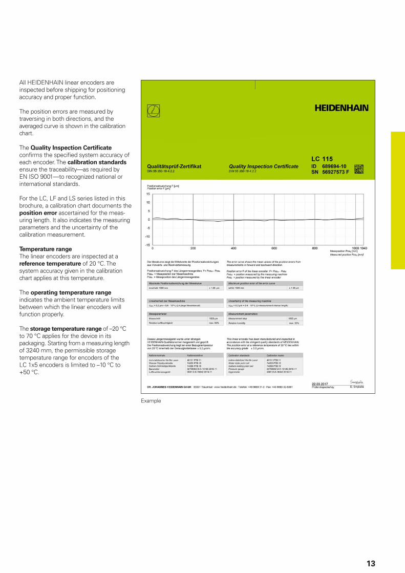
All HEIDENHAIN linear encoders are inspected before shipping for positioning accuracy and proper function.
The position errors are measured by traversing in both directions, and the averaged curve is shown in the calibration chart.
The Quality Inspection Certifi cate confi rms the specifi ed system accuracy of each encoder. The calibration standards ensure the traceability—as required by EN ISO 9001—to recognized national or international standards.
For the LC, LF and LS series listed in this brochure, a calibration chart documents the position error ascertained for the meas-uring length. It also indicates the measuring parameters and the uncertainty of the calibration measurement.
Temperature range
The linear encoders are inspected at a reference temperature of 20 °C. The system accuracy given in the calibration chart applies at this temperature.
The operating temperature range indicates the ambient temperature limits between which the linear encoders will function properly.
The storage temperature range of –20 °C to 70 °C applies for the device in its packaging. Starting from a measuring length of 3240 mm, the permissible storage temperature range for encoders of the LC 1x5 encoders is limited to –10 °C to +50 °C.
Example
// 0.1 F
LF 485
LC 415
LS 487
14
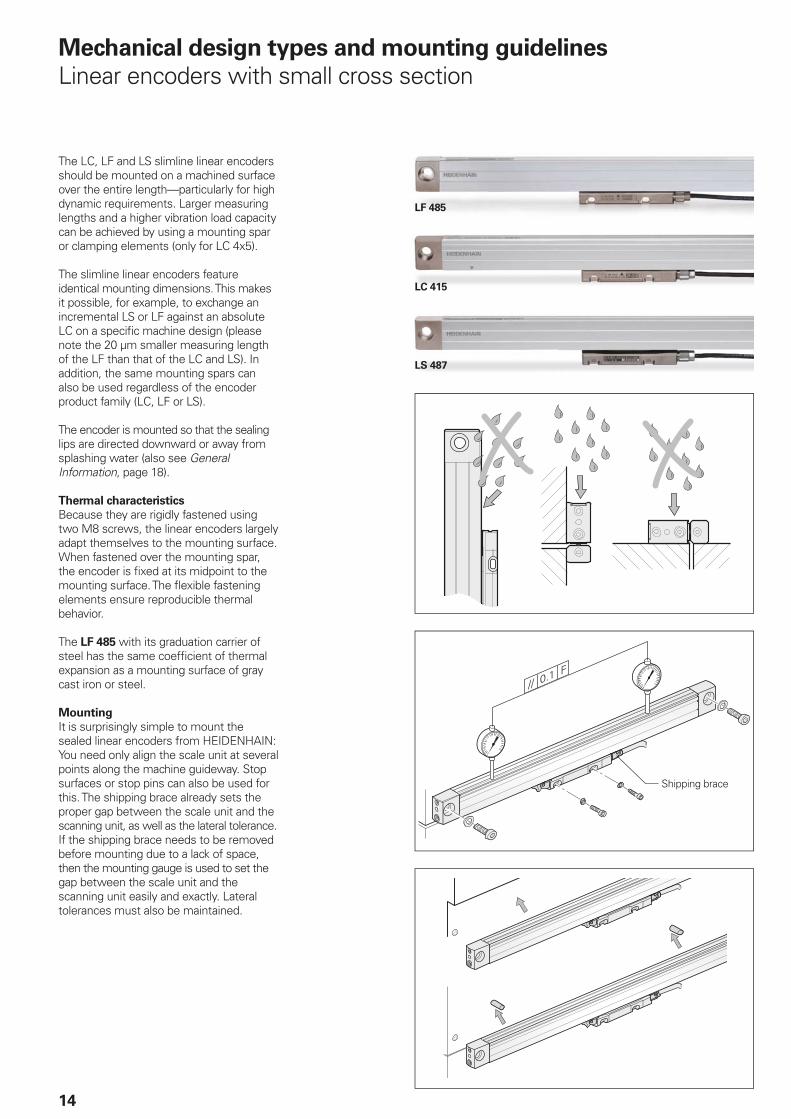
Mechanical design types and mounting guidelines
Linear encoders with small cross section
The LC, LF and LS slimline linear encoders should be mounted on a machined surface over the entire length—particularly for high dynamic requirements. Larger measuring lengths and a higher vibration load capacity can be achieved by using a mounting spar or clamping elements (only for LC 4x5).
The slimline linear encoders feature identical mounting dimensions. This makes it possible, for example, to exchange an incremental LS or LF against an absolute LC on a specifi c machine design (please note the 20 µm smaller measuring length of the LF than that of the LC and LS). In addition, the same mounting spars can also be used regardless of the encoder product family (LC, LF or LS).
The encoder is mounted so that the sealing lips are directed downward or away from splashing water (also see General Information, page 18).
Thermal characteristics
Because they are rigidly fastened using two M8 screws, the linear encoders largely adapt themselves to the mounting surface. When fastened over the mounting spar, the encoder is fi xed at its midpoint to the mounting surface. The fl exible fastening elements ensure reproducible thermal behavior.
The LF 485 with its graduation carrier of steel has the same coeffi cient of thermal expansion as a mounting surface of gray cast iron or steel.
Mounting
It is surprisingly simple to mount the sealed linear encoders from HEIDENHAIN: You need only align the scale unit at several points along the machine guideway. Stop surfaces or stop pins can also be used for this. The shipping brace already sets the proper gap between the scale unit and the scanning unit, as well as the lateral tolerance. If the shipping brace needs to be removed before mounting due to a lack of space, then the mounting gauge is used to set the gap between the scale unit and the scanning unit easily and exactly. Lateral tolerances must also be maintained.
Shipping brace
x
15
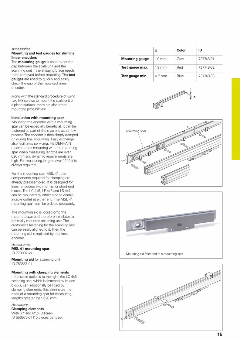
x Color ID
Mounting gauge 1.0 mm Gray 737748-01
Test gauge max. 1.3 mm Red 737748-02
Test gauge min. 0.7 mm Blue 737748-03
Accessories:Mounting and test gauges for slimline
linear encoders
The mounting gauge is used to set the gap between the scale unit and the scanning unit if the shipping brace needs to be removed before mounting. The test
gauges are used to quickly and easily check the gap of the mounted linear encoder.
Along with the standard procedure of using two M8 screws to mount the scale unit on a plane surface, there are also other mounting possibilities:
Installation with mounting spar
Mounting the encoder with a mounting spar can be especially benefi cial. It can be fastened as part of the machine assembly process. The encoder is then simply clamped on during fi nal mounting. Easy exchange also facilitates servicing. HEIDENHAIN recommends mounting with the mounting spar when measuring lengths are over 620 mm and dynamic requirements are high. For measuring lengths over 1240 it is always required.
For the mounting spar MSL 41, the components required for clamping are already preassembled. It is designed for linear encoders with normal or short end blocks. The LC 4x5, LF 4x5 and LS 4x7 can be mounted by either side to enable a cable outlet at either end. The MSL 41 mounting spar must be ordered separately.
The mounting aid is locked onto the mounted spar and therefore simulates an optimally mounted scanning unit. The customer’s fastening for the scanning unit can be easily aligned to it. Then the mounting aid is replaced by the linear encoder.
Accessories:MSL 41 mounting spar
ID 770902-xx
Mounting aid for scanning unitID 753853-01
Mounting with clamping elements
If the cable outlet is to the right, the LC 4x5 scanning unit, which is fastened by its end blocks, can additionally be fi xed by clamping elements. This eliminates the need of a mounting spar for measuring lengths greater than 620 mm.
Accessory:Clamping elements
With pin and M5x10 screwID 556975-01 (10 pieces per pack)
Mounting spar
Mounting aid fastened to a mounting spar
16
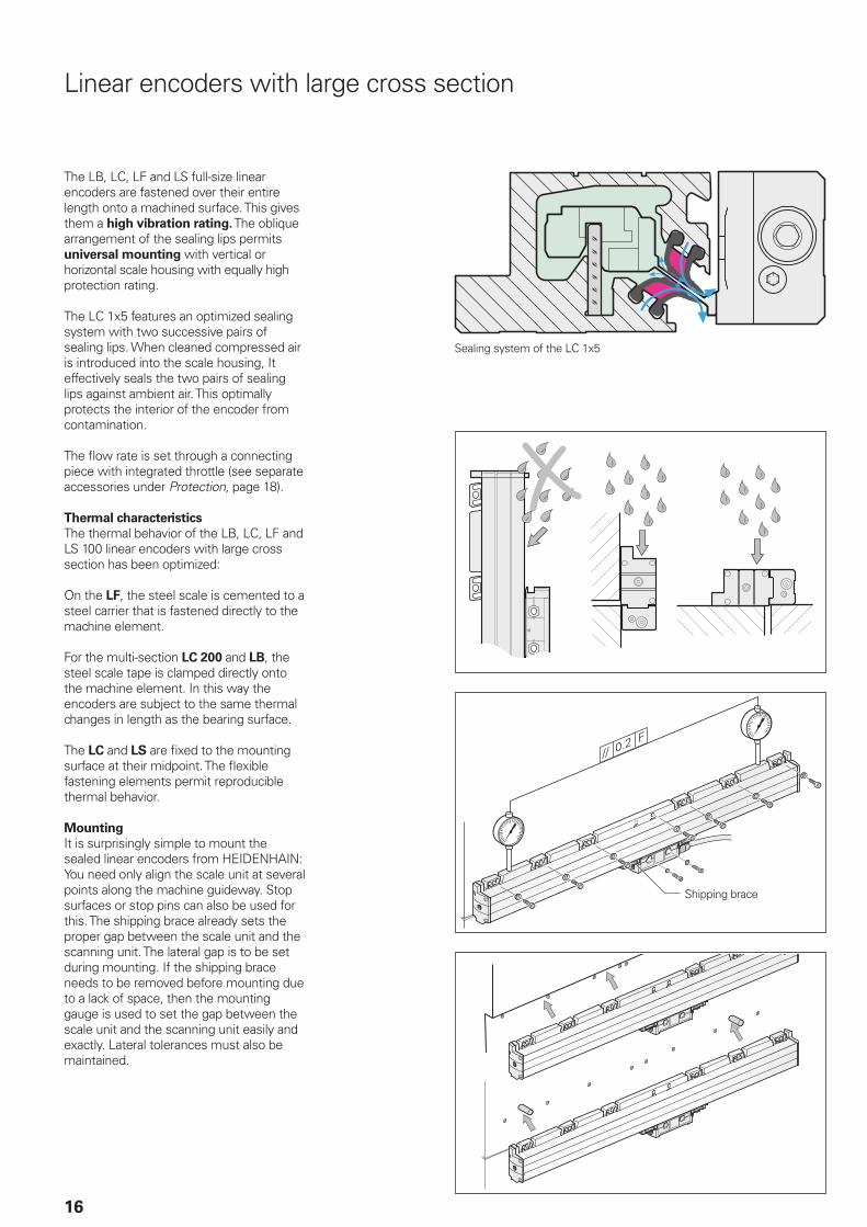
Linear encoders with large cross section
Shipping brace
The LB, LC, LF and LS full-size linear encoders are fastened over their entire length onto a machined surface. This gives them a high vibration rating. The oblique arrangement of the sealing lips permits universal mounting with vertical or horizontal scale housing with equally high protection rating.
The LC 1x5 features an optimized sealing system with two successive pairs of sealing lips. When cleaned compressed air is introduced into the scale housing, It effectively seals the two pairs of sealing lips against ambient air. This optimally protects the interior of the encoder from contamination.
The fl ow rate is set through a connecting piece with integrated throttle (see separate accessories under Protection, page 18).
Thermal characteristics
The thermal behavior of the LB, LC, LF and LS 100 linear encoders with large cross section has been optimized:
On the LF, the steel scale is cemented to a steel carrier that is fastened directly to the machine element.
For the multi-section LC 200 and LB, the steel scale tape is clamped directly onto the machine element. In this way the encoders are subject to the same thermal changes in length as the bearing surface.
The LC and LS are fi xed to the mounting surface at their midpoint. The fl exible fastening elements permit reproducible thermal behavior.
Mounting
It is surprisingly simple to mount the sealed linear encoders from HEIDENHAIN: You need only align the scale unit at several points along the machine guideway. Stop surfaces or stop pins can also be used for this. The shipping brace already sets the proper gap between the scale unit and the scanning unit. The lateral gap is to be set during mounting. If the shipping brace needs to be removed before mounting due to a lack of space, then the mounting gauge is used to set the gap between the scale unit and the scanning unit easily and exactly. Lateral tolerances must also be maintained.
Sealing system of the LC 1x5
17
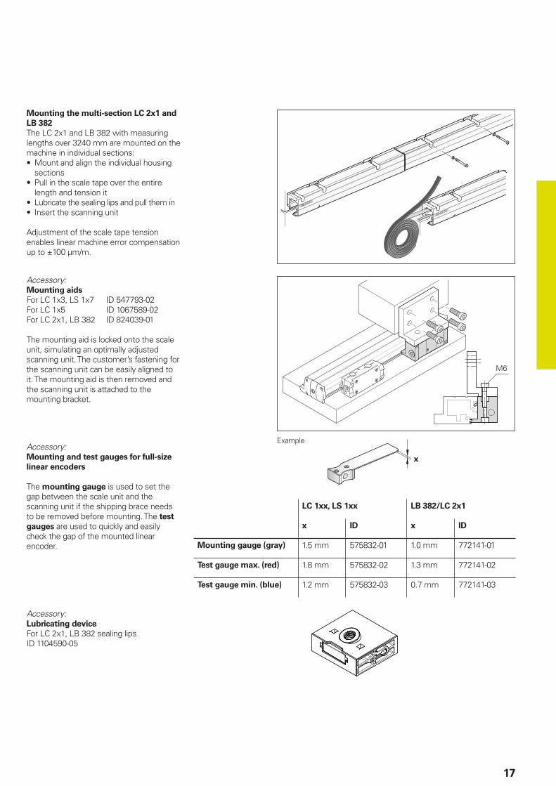
Mounting the multi-section LC 2x1 and
LB 382
The LC 2x1 and LB 382 with measuring lengths over 3240 mm are mounted on the machine in individual sections:• Mount and align the individual housing
sections• Pull in the scale tape over the entire
length and tension it• Lubricate the sealing lips and pull them in• Insert the scanning unit
Adjustment of the scale tape tension enables linear machine error compensation up to ±100 µm/m.
Accessory:Mounting aids
For LC 1x3, LS 1x7 ID 547793-02For LC 1x5 ID 1067589-02For LC 2x1, LB 382 ID 824039-01
The mounting aid is locked onto the scale unit, simulating an optimally adjusted scanning unit. The customer’s fastening for the scanning unit can be easily aligned to it. The mounting aid is then removed and the scanning unit is attached to the mounting bracket.
Accessory:Mounting and test gauges for full-size
linear encoders
The mounting gauge is used to set the gap between the scale unit and the scanning unit if the shipping brace needs to be removed before mounting. The test
gauges are used to quickly and easily check the gap of the mounted linear encoder.
LC 1xx, LS 1xx LB 382/LC 2x1
x ID x ID
Mounting gauge (gray) 1.5 mm 575832-01 1.0 mm 772141-01
Test gauge max. (red) 1.8 mm 575832-02 1.3 mm 772141-02
Test gauge min. (blue) 1.2 mm 575832-03 0.7 mm 772141-03
Example
Accessory:Lubricating device
For LC 2x1, LB 382 sealing lipsID 1104590-05
DA 400
18
General information
Protection
Sealed linear encoders fulfi ll the require-ments for IP53 protection according to EN 60 529 or IEC 60 529 provided that they are mounted with the sealing lips facing away from splash water. If necessary, provide a separate protective cover. If the encoder is exposed to particularly heavy concentrations of coolant and mist, compressed air can be used to provide IP64 protection to more effectively prevent the ingress of contamination. To apply the pressurized air for sealing the housing, the LB, LC, LF and LS sealed linear encoders are therefore equipped with inlets at both end pieces and on the mounting block of the scanning unit.
The compressed air introduced directly onto the encoders must be cleaned by a microfi lter and must comply with the following quality classes as per ISO 8573-1 (2010 edition):• Solid contaminants: Class 1
Particle size No. of particles per m3
0.1 µm to 0.5 µm 20 0000.5 µm to 1.0 µm 4001.0 µm to 5.0 µm 10
• Max. pressure dew point: Class 4
(pressure dew point at 3 °C)• Total oil content: Class 1
(max. oil concentration 0.01 mg/m3)
For an optimal supply of sealing air to the sealed linear encoders, the required air fl ow is 7 l/min to 10 l/min per encoder. Ideally, the air fl ow is regulated by the HEIDENHAIN connecting pieces with integrated throttle The throttles ensure the prescribed fl ow quantities at an input pressure of approx. 1 · 105 Pa (1 bar).
Accessory:Connecting piece, straight
With throttle and gasketID 226270-02
Connecting piece, straight, short
With throttle and gasketID 275239-01
Also suitable:Swiveling screw fi tting 90°
With sealID 207834-02
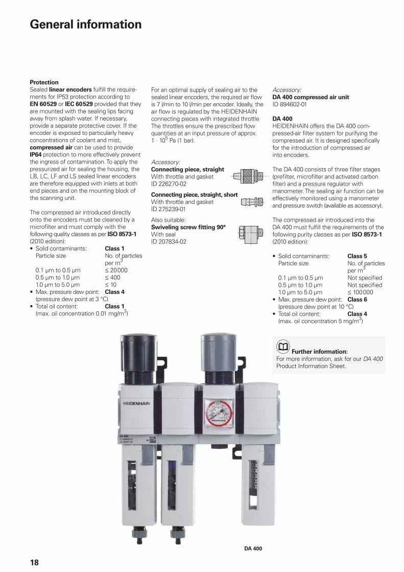
Accessory:DA 400 compressed air unit
ID 894602-01
DA 400
HEIDENHAIN offers the DA 400 com-pressed-air fi lter system for purifying the compressed air. It is designed specifi cally for the introduction of compressed air into encoders.
The DA 400 consists of three fi lter stages (prefi lter, microfi lter and activated carbon fi lter) and a pressure regulator with manometer. The sealing air function can be effectively monitored using a manometer and pressure switch (available as accessory).
The compressed air introduced into the DA 400 must fulfi ll the requirements of the following purity classes as per ISO 8573-1 (2010 edition):
• Solid contaminants: Class 5
Particle size No. of particles per m3
0.1 µm to 0.5 µm Not specifi ed0.5 µm to 1.0 µm Not specifi ed1.0 µm to 5.0 µm 100 000
• Max. pressure dew point: Class 6
(pressure dew point at 10 °C)• Total oil content: Class 4
(max. oil concentration 5 mg/m3)
Further information:
For more information, ask for our DA 400 Product Information Sheet.
19
Mounting
To simplify cable routing, the mounting block of the scanning unit is usually screwed onto a stationary machine part, and the scale housing on the moving part. The mounting location for the linear encoders should be carefully considered in order to ensure both optimum accuracy and the longest possible service life.• The encoder should be mounted as
closely as possible to the working plane to keep the Abbe error low.
• To function properly, linear encoders must not be continuously subjected to strong vibration; the more solid parts of the machine tool provide the best mounting surface in this respect. Encoders should not be mounted on hollow parts or with adapters. A mounting spar is recommended for sealed linear encoders with small cross section
• The linear encoders should be mounted away from sources of heat to avoid temperature infl uences
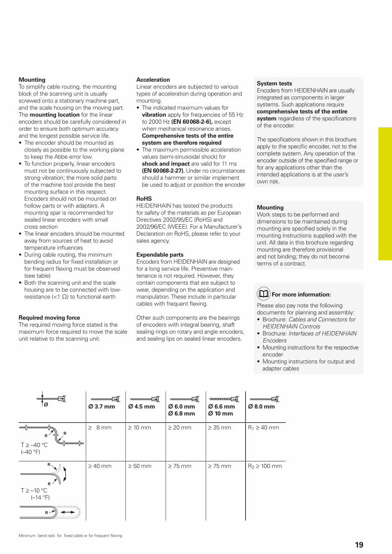
• During cable routing, the minimum bending radius for fi xed installation or for frequent fl exing must be observed (see table)
• Both the scanning unit and the scale housing are to be connected with low-resistance (<1 ) to functional earth
Required moving force
The required moving force stated is the maximum force required to move the scale unit relative to the scanning unit.
Acceleration
Linear encoders are subjected to various types of acceleration during operation and mounting.• The indicated maximum values for
vibration apply for frequencies of 55 Hz to 2000 Hz (EN 60 068-2-6), except when mechanical resonance arises. Comprehensive tests of the entire
system are therefore required
• The maximum permissible acceleration values (semi-sinusoidal shock) for shock and impact are valid for 11 ms (EN 60 068-2-27). Under no circumstances should a hammer or similar implement be used to adjust or position the encoder
RoHS
HEIDENHAIN has tested the products for safety of the materials as per European Directives 2002/95/EC (RoHS) and 2002/96/EC (WEEE). For a Manufacturer’s Declaration on RoHS, please refer to your sales agency.
Expendable parts
Encoders from HEIDENHAIN are designed for a long service life. Preventive main-tenance is not required. However, they contain components that are subject to wear, depending on the application and manipulation. These include in particular cables with frequent fl exing.
Other such components are the bearings of encoders with integral bearing, shaft sealing rings on rotary and angle encoders, and sealing lips on sealed linear encoders.
System tests
Encoders from HEIDENHAIN are usually integrated as components in larger systems. Such applications require comprehensive tests of the entire
system regardless of the specifi cations of the encoder.
The specifi cations shown in this brochure apply to the specifi c encoder, not to the complete system. Any operation of the encoder outside of the specifi ed range or for any applications other than the intended applications is at the user’s own risk.
Mounting
Work steps to be performed and dimensions to be maintained during mounting are specifi ed solely in the mounting instructions supplied with the unit. All data in this brochure regarding mounting are therefore provisional and not binding; they do not become terms of a contract.
For more information:
Please also pay note the following documents for planning and assembly:• Brochure: Cables and Connectors for
HEIDENHAIN Controls• Brochure: Interfaces of HEIDENHAIN
Encoders• Mounting instructions for the respective
encoder• Mounting instructions for output and
adapter cables
3.7mm 4.5mm 6.0mm
6.8mm
6.6 mm
10 mm
8.0 mm
T –40 °C(–40 °F)
8 mm 10 mm 20 mm 35 mm R1 40 mm
T –10 °C(–14 °F)
40 mm 50 mm 75 mm 75 mm R2 100 mm
Minimum bend radii for fi xed cable or for frequent fl exing
20
Functional safety
Safe axes
Driven axes on machine tools usually represent a great hazard for humans. Particularly if the human interacts with the machine (e.g. during workpiece setup), it must be ensured that the machine does not make any uncontrolled movements. Here the position information of axes is needed to conduct a safety function. As an evaluating safety module, the control has the task of detecting faulty position information and reacting to it accordingly.
Various safety strategies can be pursued depending on the topology of the axis and the evaluation capabilities of the control. In a single-encoder system, for example, only one encoder per axis is evaluated for the safety function. However, on axes with two encoders, e.g. linear axis with a rotary and a linear encoder, the two redundant position values can be compared with each other in the control.
Safe fault detection can be ensured only if the two components—control and encoder—are properly adapted to one another. Here it is to be noted that the safety designs of control manufacturers differ from one another. This also means that the requirements on the connected encoders sometimes differ.
Type-examined encoders
Sealed linear encoders from HEIDENHAIN are used successfully on a variety of controls in widely differing safety designs. This applies particularly to the type-approved encoders LC 1x5/LC 4x5 with EnDat and DRIVE-CLiQ interfaces. The encoders can be operated as single-encoder systems in conjunction with a suitable control in applications with the control category SIL-2 (according to EN 61 508) or performance level “d” (of EN ISO 13 849). Unlike incremental encoders, the absolute LC 1x5/LC 4x5 linear encoders always provide a safe absolute position value—including immediately after switch-on or a power failure. Reliable transmission of the position is based on two independently generated absolute position values and on error bits, which are provided to the safe control. The purely serial data transmission also offers other advantages, such as greater reliability, improved accuracy, diagnostic capabilities, and reduced costs through simpler connection technology.
DRIVE-CLiQ is a registered trademark of SIEMENS AG.
Standard encoders
In addition to the encoders explicitly qualifi ed for safety applications, standard linear encoders , e.g. with Fanuc interface or 1 VPP signals, can also be used in safe axes. In these cases, the properties of the encoders are to be aligned with the requirements of the respective control. HEIDENHAIN can provide additional data on the individual encoders (failure rate, fault model as per EN 61 800-5-2).
For more information:
The safety-related characteristic values are listed in the specifi cations of the encoders. The Technical Information document Safety-Related Position Encoders provides explanations of the characteristic values.Upon request, HEIDENHAIN can likewise provide additional data about the individual products (failure rate, fault model as per EN 61 800-5-2) for the use of standard encoders in safety-related applications.
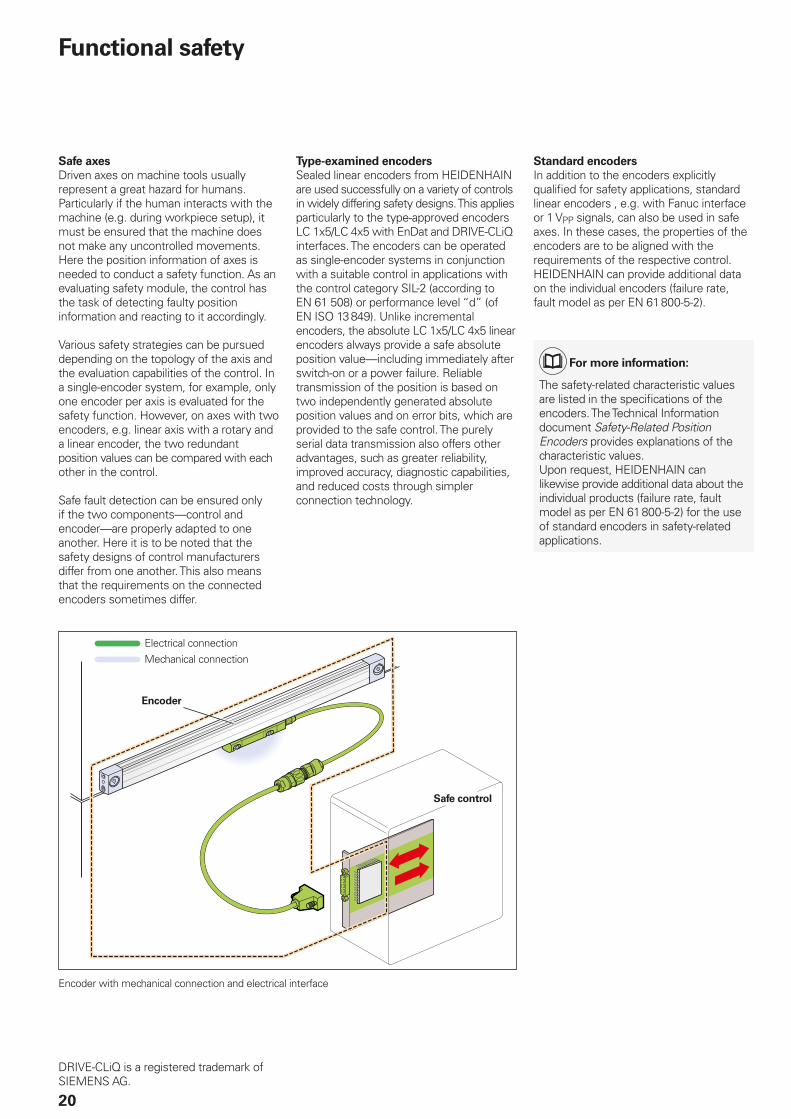
Encoder with mechanical connection and electrical interface
Electrical connection
Mechanical connection
Encoder
Safe control
21
Fault exclusion against loosening of the
mechanical connection
Regardless of the interface, many safety designs require a safe mechanical connection. The standard for electrical drives, EN 61 800-5-2, defi nes the loss or loosening of the mechanical connection between the encoder and drive as a fault that requires consideration. Since it cannot be guaranteed that the control will detect such errors, in many cases the possibility of a fault must be eliminated. The
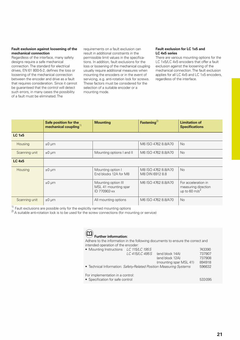
Safe position for the
mechanical coupling1)
Mounting Fastening2)
Limitation of
Specifi cations
LC 1x5
Housing ±0 µm M6 ISO 4762 8.8/A70 No
Scanning unit ±0 µm Mounting options I and II M6 ISO 4762 8.8/A70 No
LC 4x5
Housing ±0 µm Mounting option IEnd blocks 12A for M8
M8 ISO 4762 8.8/A70M8 DIN 6912 8.8
No
±0 µm Mounting option IIIMSL 41 mounting sparID 770902-xx
M6 ISO 4762 8.8/A70 For acceleration in measuring direction up to 60 m/s2
Scanning unit ±0 µm All mounting options M6 ISO 4762 8.8/A70 No
1) Fault exclusions are possible only for the explicitly named mounting options2) A suitable anti-rotation lock is to be used for the screw connections (for mounting or service)
requirements on a fault exclusion can result in additional constraints in the permissible limit values in the specifi ca-tions. In addition, fault exclusions for the loss or loosening of the mechanical coupling usually require additional measures when mounting the encoders or in the event of servicing, e.g. anti-rotation lock for screws. These factors must be considered for the selection of a suitable encoder or a mounting mode.
Further information:
Adhere to the information in the following documents to ensure the correct and intended operation of the encoder:• Mounting Instructions LC 115/LC 195 S 743390
LC 415/LC 495 S (end block 14A) 737907 (end block 12A) 737908 (mounting spar MSL 41) 894918
• Technical Information: Safety-Related Position Measuring Systems 596632
For implementation in a control:• Specifi cation for safe control 533 095
Fault exclusion for LC 1x5 and
LC 4x5 series
There are various mounting options for the LC 1x5/LC 4x5 encoders that offer a fault exclusion against the loosening of the mechanical connection. The fault exclusion applies for all LC 4x5 and LC 1x5 encoders, regardless of the interface.
ML 70 120 170 220 270 320 370 420 470 520 570 620 670 720 770 820 920 1020 1140 1240 1340 1440 1540 1640 1740 1840 2040
L 37.5 55 75 100 115 140 175 200 225 250 275 300 325 350 375 400 450 500 555 610 655 710 760 810 855 910 1010
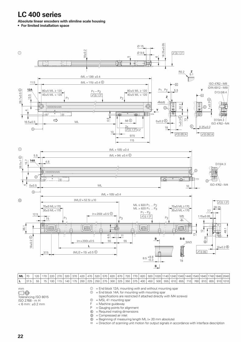
22
LC 400 seriesAbsolute linear encoders with slimline scale housing
• For limited installation space
= End block 12A; mounting with and without mounting spar = End block 14A; for mounting with mounting spar
(specifi cations are restricted if attached directly with M4 screws) = MSL 41 mounting sparF = Machine guidewayP = Gauging points for alignmentⓀ = Required mating dimensionsⒹ = Compressed air inletⓈ = Beginning of measuring length ML (= 20 mm absolute) = Direction of scanning unit motion for output signals in accordance with interface description
23
Sp
ecifi c
ati
on
s
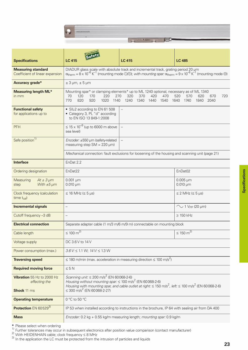
Specifi cations LC 415 LC 415 LC 485
Measuring standard
Coeffi cient of linear expansionDIADUR glass scale with absolute track and incremental track, grating period 20 µmtherm 8 x 10⁻⁶ K–1 (mounting mode /); with mounting spar: therm 9 x 10⁻⁶ K–1 (mounting mode )
Accuracy grade* ± 3 µm, ± 5 µm
Measuring length ML* in mm
Mounting spar* or clamping elements* up to ML 1240 optional, necessary as of ML 1340 70 120 170 220 270 320 370 420 470 520 570 620 670 720770 820 920 1020 1140 1240 1340 1440 1540 1640 1740 1840 2040
Functional safety
for applications up to• SIL-2 according to EN 61 508• Category 3, PL “d” according
to EN ISO 13 849-1:2008
–
PFH 15 x 10–9 (up to 6000 m above sea level)
–
Safe position1) Encoder: ±550 µm (safety-related measuring step SM = 220 µm)
–
Mechanical connection: fault exclusions for loosening of the housing and scanning unit (page 21)
Interface EnDat 2.2
Ordering designation EnDat22 EnDat02
Measuring At ± 3 µmstep With ±5 µm
0.001 µm0.010 µm
0.005 µm0.010 µm
Clock frequency (calculation time tcal)
16 MHz ( 5 µs) 2 MHz ( 5 µs)
Incremental signals – 1VPP (20 µm)
Cutoff frequency –3 dB – 150 kHz
Electrical connection Separate adapter cable (1 m/3 m/6 m/9 m) connectable on mounting block
Cable length 100m2) 150m2)
Voltage supply DC 3.6 V to 14 V
Power consumption (max.) 3.6 V: 1.1 W; 14 V: 1.3 W
Traversing speed 180m/min(max. acceleration in measuring direction 100 m/s2)
Required moving force 5 N
Vibration 55 Hz to 2000 Hzeffecting the
Shock 11 ms
Scanning unit: 200 m/s2 (EN 60 068-2-6)Housing without mounting spar: 100 m/s2 (EN 60 068-2-6)Housing with mounting spar, and cable outlet at right: 150 m/s2, left: 100 m/s2 (EN 60 068-2-6) 300 m/s2 (EN 60 068-2-27)
Operating temperature 0 °C to 50 °C
Protection EN 60 5293) IP 53 when installed according to instructions in the brochure, IP 64 with sealing air from DA 400
Mass Encoder: 0.2 kg + 0.55 kg/m measuring length; mounting spar: 0.9 kg/m
* Please select when ordering1)
Further tolerances may occur in subsequent electronics after position value comparison (contact manufacturer)2)
With HEIDENHAIN cable; clock frequency 8 MHz3) In the application the LC must be protected from the intrusion of particles and liquids
24
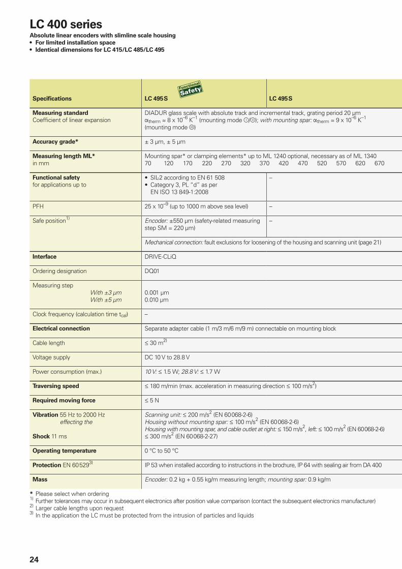
Specifi cations LC 495 S LC 495 S
Measuring standard
Coeffi cient of linear expansionDIADUR glass scale with absolute track and incremental track, grating period 20 µmtherm 8 x 10⁻⁶ K–1 (mounting mode /); with mounting spar: therm 9 x 10⁻⁶ K–1 (mounting mode )
Accuracy grade* ± 3 µm, ± 5 µm
Measuring length ML* in mm
Mounting spar* or clamping elements* up to ML 1240 optional, necessary as of ML 134070 120 170 220 270 320 370 420 470 520 570 620 670
Functional safety
for applications up to• SIL-2 according to EN 61 508• Category 3, PL “d” as per
EN ISO 13 849-1:2008
–
PFH 25 x 10–9 (up to 1000 m above sea level) –
Safe position1) Encoder: ±550 µm (safety-related measuring step SM = 220 µm)
–
Mechanical connection: fault exclusions for loosening of the housing and scanning unit (page 21)
Interface DRIVE-CLiQ
Ordering designation DQ01
Measuring step With ±3 µm With ±5 µm
0.001 µm0.010 µm
Clock frequency (calculation time tcal) –
Electrical connection Separate adapter cable (1 m/3 m/6 m/9 m) connectable on mounting block
Cable length 30m2)
Voltage supply DC 10 V to 28.8 V
Power consumption (max.) 10 V: 1.5 W; 28.8 V: 1.7 W
Traversing speed 180 m/min (max. acceleration in measuring direction 100 m/s2)
Required moving force 5 N
Vibration 55 Hz to 2000 Hzeffecting the
Shock 11 ms
Scanning unit: 200 m/s2 (EN 60 068-2-6)Housing without mounting spar: 100 m/s2 (EN 60 068-2-6)Housing with mounting spar, and cable outlet at right: 150 m/s2, left: 100 m/s2 (EN 60 068-2-6) 300 m/s2 (EN 60 068-2-27)
Operating temperature 0 °C to 50 °C
Protection EN 60 5293) IP 53 when installed according to instructions in the brochure, IP 64 with sealing air from DA 400
Mass Encoder: 0.2 kg + 0.55 kg/m measuring length; mounting spar: 0.9 kg/m
* Please select when ordering1)
Further tolerances may occur in subsequent electronics after position value comparison (contact the subsequent electronics manufacturer)2) Larger cable lengths upon request3) In the application the LC must be protected from the intrusion of particles and liquids
LC 400 seriesAbsolute linear encoders with slimline scale housing
• For limited installation space
• Identical dimensions for LC 415/LC 485/LC 495
25
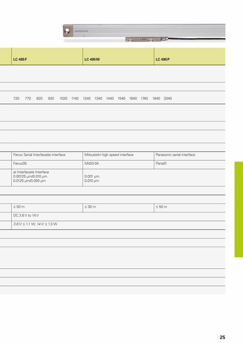
LC 495 F LC 495 M LC 495 P
720 770 820 920 1020 1140 1240 1340 1440 1540 1640 1740 1840 2040
Fanuc Serial Interface/i interface Mitsubishi high speed interface Panasonic serial interface
Fanuc05 Mit03-04 Pana01
iInterface/Interface0.00125µm/0.010 µm0.0125 µm/0.050 µm
0.001 µm0.010 µm
50m 30m 50m
DC 3.6 V to 14 V
3.6 V: 1.1 W; 14 V: 1.3 W
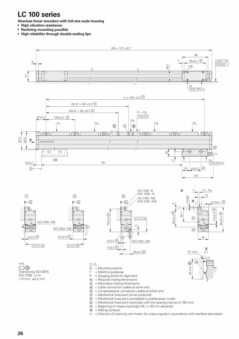
26
LC 100 seriesAbsolute linear encoders with full-size scale housing
• High vibration resistance
• Reclining mounting possible
• High reliability through double sealing lips
=Mounting optionsF = Machine guidewayP = Gauging points for alignmentⓀ = Required mating dimensionsⒶ = Alternative mating dimensions Ⓑ = Cable connection usable at either endⒹ = Compressed-air connection usable at either endⓉ = Mechanical fi xed point (to be preferred)Ⓗ = Mechanical fi xed point compatible to predecessor modelⒼ = Mechanical fi xed point (coincides with the spacing interval of 100 mm)Ⓢ = Beginning of measuring length ML (= 20 mm absolute)Ⓦ = Mating surfaces = Direction of scanning unit motion for output signals in accordance with interface description
27
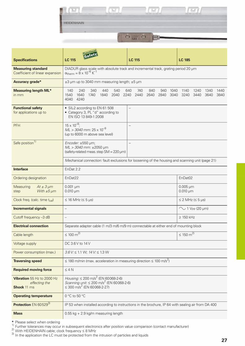
Specifi cations LC 115 LC 115 LC 185
Measuring standard
Coeffi cient of linear expansionDIADUR glass scale with absolute track and incremental track, grating period 20 µmtherm 8 x 10⁻⁶ K–1
Accuracy grade* ±3 µm up to 3040 mm measuring length; ±5 µm
Measuring length ML* in mm
140 240 340 440 540 640 740 840 940 1040 1140 1240 1340 14401540 1640 1740 1840 2040 2240 2440 2640 2840 3040 3240 3440 3640 38404040 4240
Functional safety
for applications up to• SIL-2 according to EN 61 508• Category 3, PL “d” according to
EN ISO 13 849-1:2008
–
PFH 15 x 10–9;ML > 3040 mm: 25 x 10–9 (up to 6000 m above sea level)
–
Safe position1) Encoder: ±550 µm;ML > 3040 mm: ±2050 µm(safety-related meas. step SM = 220 µm)
–
Mechanical connection: fault exclusions for loosening of the housing and scanning unit (page 21)
Interface EnDat 2.2
Ordering designation EnDat22 EnDat02
Measuring At ± 3 µmstep With ±5 µm
0.001 µm0.010 µm
0.005 µm0.010 µm
Clock freq. (calc. time tcal) 16 MHz ( 5 µs) 2 MHz ( 5 µs)
Incremental signals – 1VPP(20µm)
Cutoff frequency –3 dB – 150 kHz
Electrical connection Separate adapter cable (1 m/3 m/6 m/9 m) connectable at either end of mounting block
Cable length 100m2) 150m2)
Voltage supply DC 3.6 V to 14 V
Power consumption (max.) 3.6 V: 1.1 W; 14 V: 1.3 W
Traversing speed 180m/min(max. acceleration in measuring direction 100 m/s2)
Required moving force 4 N
Vibration 55 Hz to 2000 Hzeffecting the
Shock 11 ms
Housing: 200 m/s2 (EN 60 068-2-6)Scanning unit: 200 m/s2 (EN 60 068-2-6) 300 m/s2 (EN 60 068-2-27)
Operating temperature 0 °C to 50 °C
Protection EN 60 5293) IP 53 when installed according to instructions in the brochure, IP 64 with sealing air from DA 400
Mass 0.55 kg + 2.9 kg/m measuring length
* Please select when ordering1) Further tolerances may occur in subsequent electronics after position value comparison (contact manufacturer)2)
With HEIDENHAIN cable; clock frequency 8 MHz3) In the application the LC must be protected from the intrusion of particles and liquids
28
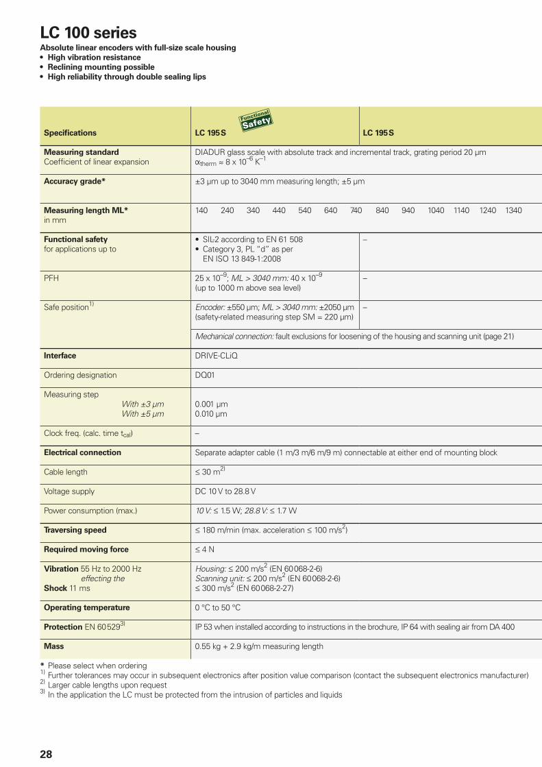
Specifi cations LC 195 S LC 195 S
Measuring standard
Coeffi cient of linear expansionDIADUR glass scale with absolute track and incremental track, grating period 20 µmtherm 8 x 10⁻⁶ K–1
Accuracy grade* ±3 µm up to 3040 mm measuring length; ±5 µm
Measuring length ML* in mm
140 240 340 440 540 640 740 840 940 1040 1140 1240 1340
Functional safety
for applications up to• SIL-2 according to EN 61 508• Category 3, PL “d” as per
EN ISO 13 849-1:2008
–
PFH 25 x 10–9; ML > 3040 mm: 40 x 10–9 (up to 1000 m above sea level)
–
Safe position1) Encoder: ±550 µm; ML > 3040 mm: ±2050 µm(safety-related measuring step SM = 220 µm)
–
Mechanical connection: fault exclusions for loosening of the housing and scanning unit (page 21)
Interface DRIVE-CLiQ
Ordering designation DQ01
Measuring step With ±3 µm With ±5 µm
0.001 µm0.010 µm
Clock freq. (calc. time tcal) –
Electrical connection Separate adapter cable (1 m/3 m/6 m/9 m) connectable at either end of mounting block
Cable length 30m2)
Voltage supply DC 10 V to 28.8 V
Power consumption (max.) 10 V: 1.5 W; 28.8 V: 1.7 W
Traversing speed 180 m/min (max. acceleration 100 m/s2)
Required moving force 4 N
Vibration 55 Hz to 2000 Hzeffecting the
Shock 11 ms
Housing: 200 m/s2 (EN 60 068-2-6)Scanning unit: 200 m/s2 (EN 60 068-2-6) 300 m/s2 (EN 60 068-2-27)
Operating temperature 0 °C to 50 °C
Protection EN 60 5293) IP 53 when installed according to instructions in the brochure, IP 64 with sealing air from DA 400
Mass 0.55 kg + 2.9 kg/m measuring length
* Please select when ordering1)
Further tolerances may occur in subsequent electronics after position value comparison (contact the subsequent electronics manufacturer)2) Larger cable lengths upon request3) In the application the LC must be protected from the intrusion of particles and liquids
LC 100 seriesAbsolute linear encoders with full-size scale housing
• High vibration resistance
• Reclining mounting possible
• High reliability through double sealing lips
29
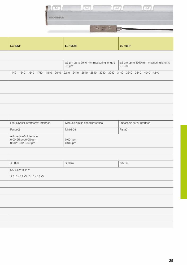
LC 195 F LC 195 M LC 195 P
±3 µm up to 2040 mm measuring length; ±5 µm
±3 µm up to 3040 mm measuring length; ±5 µm
1440 1540 1640 1740 1840 2040 2240 2440 2640 2840 3040 3240 3440 3640 3840 4040 4240
Fanuc Serial Interface/i interface Mitsubishi high speed interface Panasonic serial interface
Fanuc05 Mit03-04 Pana01
iInterface/Interface0.00125µm/0.010 µm0.0125 µm/0.050 µm
0.001 µm0.010 µm
50m 30m 50m
DC 3.6 V to 14 V
3.6 V: 1.1 W; 14 V: 1.3 W
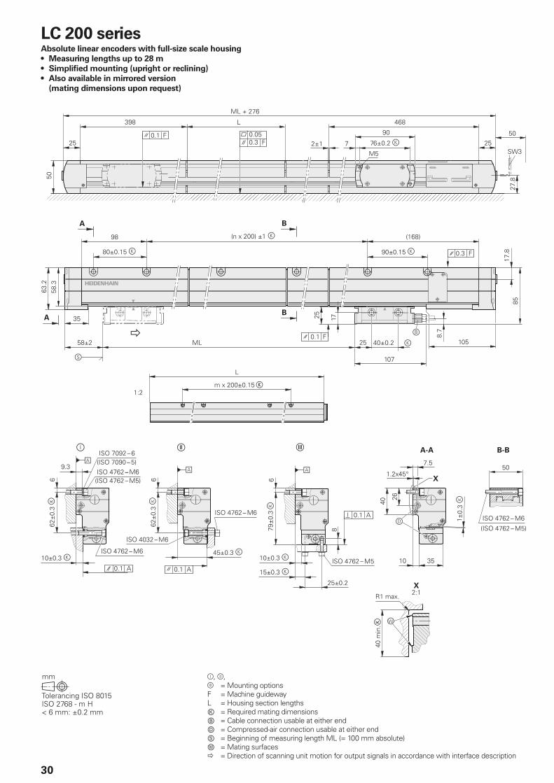
30
LC 200 seriesAbsolute linear encoders with full-size scale housing
• Measuring lengths up to 28 m
• Simplifi ed mounting (upright or reclining)
• Also available in mirrored version
(mating dimensions upon request)
,, =Mounting optionsF =Machine guidewayL = Housing section lengthsⓀ = Required mating dimensionsⒷ = Cable connection usable at either endⒹ = Compressed-air connection usable at either endⓈ = Beginning of measuring length ML (= 100 mm absolute)Ⓦ = Mating surfaces = Direction of scanning unit motion for output signals in accordance with interface description
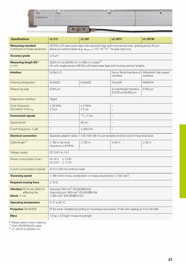
31
Specifi cations LC 211 LC 281 LC 291 F LC 291 M
Measuring standard
Coeffi cient of linear expansionMETALLUR steel scale tape with absolute track and incremental track, grating period 40 µmSame as machine base (e.g. therm 10 x 10–6 K–1 for gray cast iron)
Accuracy grade ± 5 µm
Measuring length ML*
in mm3240 mm to 28 040 mm in 200 mm steps2)
Kit with single-section METALLUR steel scale tape and housing section lengths
Interface EnDat 2.2 Fanuc Serial Interface i interface
Mitsubishi high speed interface
Ordering designation EnDat22 EnDat02 Fanuc05 Mit03-04
Measuring step 0.010 µm iInterface/Interface0.0125 µm/0.050 µm
0.010 µm
Diagnostics interface Digital
Clock frequencyCalculation time tcal
16 MHz 5 µs
2 MHz 5 µs
––
Incremental signals – 1 VPP –
Signal period – 40 µm –
Cutoff frequency –3 dB – 250 kHz –
Electrical connection Separate adapter cable (1 m/3 m/6 m/9 m) connectable at either end of mounting block
Cable length1) 100m(atclock frequency8MHz)
150 m 50 m 30 m
Voltage supply DC 3.6 V to 14 V
Power consumption (max.) At 14 V: 1.3 WAt 3.6 V: 1.1 W
Current consumption (typical) At 5 V: 225 mA (without load)
Traversing speed 180 m/min (max. acceleration in measuring direction 100 m/s2)
Required moving force 15 N
Vibration 55 Hz bis 2000 Hzeffecting the
Shock 11 ms
Housing: 200 m/s2 (EN 60 068-2-6)Scanning unit: 300 m/s2 (EN 60 068-2-6) 300 m/s2 (EN 60 068-2-27)
Operating temperature 0 °C to 50 °C
Protection EN 60 529 IP 53 when installed according to mounting instructions, IP 64 with sealing air from DA 400
Mass 1.3 kg + 3.6 kg/m measuring length
* Please select when ordering1)
With HEIDENHAIN cable2)
LC 291 M to 20 040 mm
32
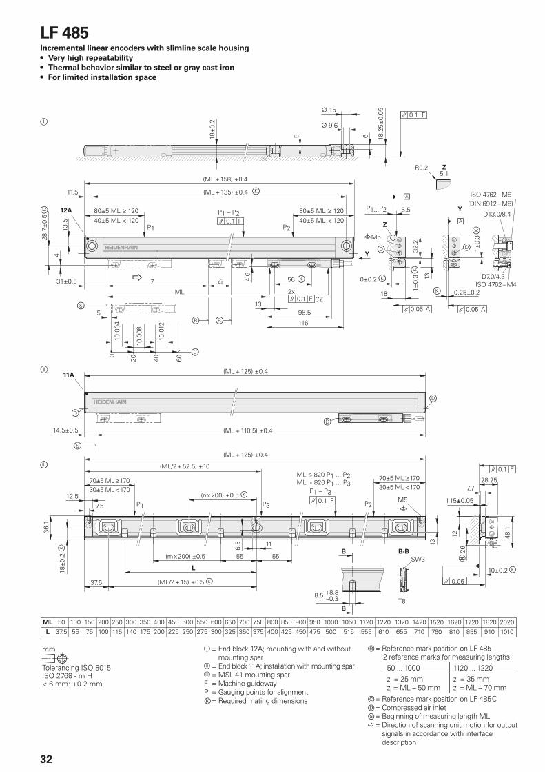
LF 485Incremental linear encoders with slimline scale housing
• Very high repeatability
• Thermal behavior similar to steel or gray cast iron
• For limited installation space
= End block12A;mountingwithandwithout mounting spar
= End block 11A; installation with mounting spar = MSL 41 mounting sparF = Machine guidewayP = Gauging points for alignmentⓀ = Required mating dimensions
Ⓡ = Reference mark position on LF 4852 reference marks for measuring lengths50 ... 1000 1120 ... 1220z = 25 mmzi = ML – 50 mm
z = 35 mmzi = ML – 70 mm
Ⓒ = Reference mark position on LF 485 CⒹ = Compressed air inletⓈ = Beginning of measuring length ML = Direction of scanning unit motion for output
signals in accordance with interface description
33
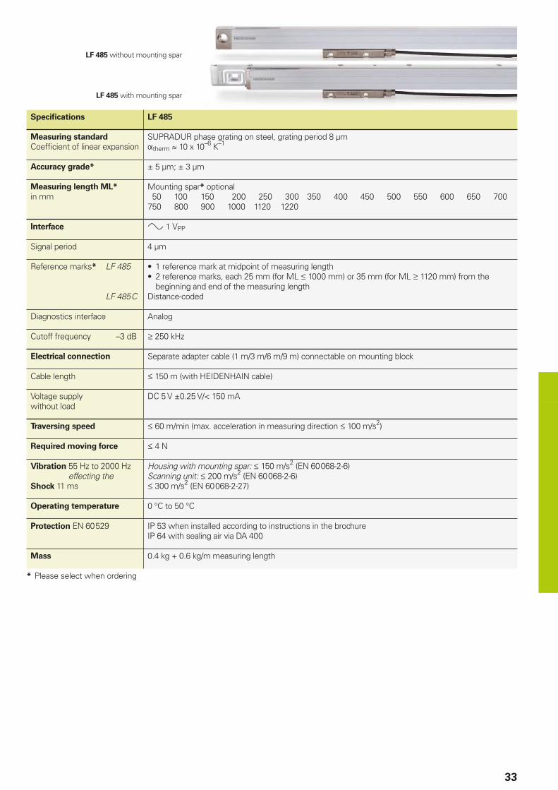
Specifi cations LF 485
Measuring standard
Coeffi cient of linear expansionSUPRADUR phase grating on steel, grating period 8 µmtherm 10 x 10–6 K–1
Accuracy grade* ± 5 µm; ± 3 µm
Measuring length ML*
in mmMounting spar* optional 50 100 150 200 250 300 350 400 450 500 550 600 650 700750 800 900 1000 1120 1220
Interface 1VPP
Signal period 4 µm
Reference marks* LF 485
LF 485 C
• 1 reference mark at midpoint of measuring length• 2 reference marks, each 25 mm (for ML 1000 mm) or 35 mm (for ML 1120 mm) from the
beginning and end of the measuring lengthDistance-coded
Diagnostics interface Analog
Cutoff frequency –3 dB 250 kHz
Electrical connection Separate adapter cable (1 m/3 m/6 m/9 m) connectable on mounting block
Cable length 150 m (with HEIDENHAIN cable)
Voltage supply without load
DC 5 V ±0.25 V/< 150 mA
Traversing speed 60 m/min (max. acceleration in measuring direction 100 m/s2)
Required moving force 4 N
Vibration 55 Hz to 2000 Hzeffecting the
Shock 11 ms
Housing with mounting spar: 150 m/s2 (EN 60 068-2-6)Scanning unit: 200 m/s2 (EN 60 068-2-6) 300 m/s2 (EN 60 068-2-27)
Operating temperature 0 °C to 50 °C
Protection EN 60 529 IP 53 when installed according to instructions in the brochureIP 64 with sealing air via DA 400
Mass 0.4 kg + 0.6 kg/m measuring length
* Please select when ordering
LF 485 without mounting spar
LF 485 with mounting spar
34
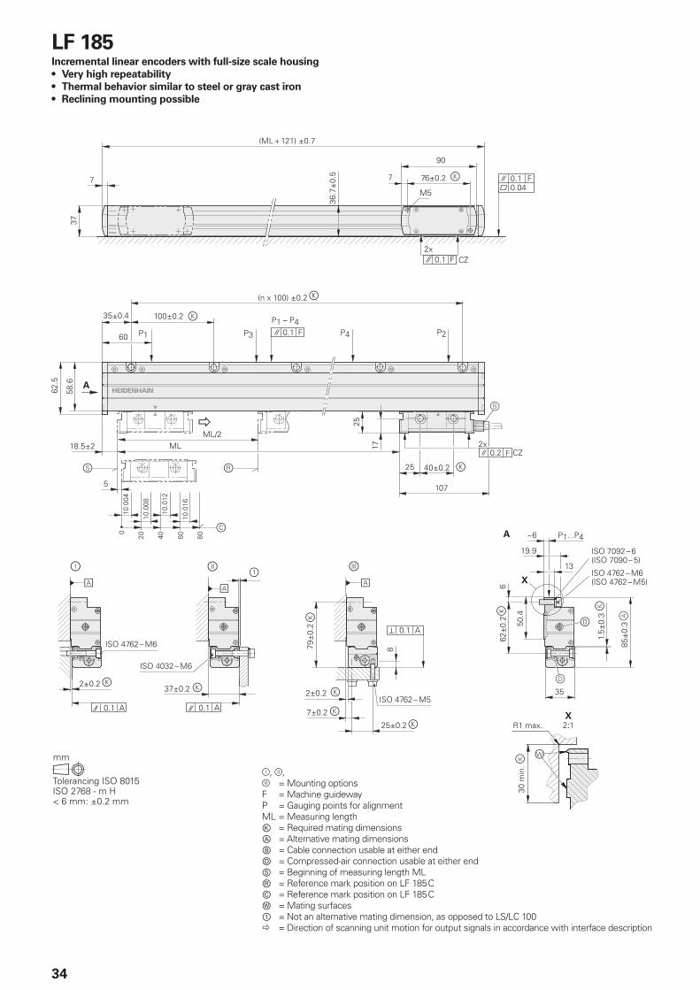
LF 185Incremental linear encoders with full-size scale housing
• Very high repeatability
• Thermal behavior similar to steel or gray cast iron
• Reclining mounting possible
=Mounting optionsF = Machine guidewayP = Gauging points for alignmentML = Measuring lengthⓀ = Required mating dimensionsⒶ = Alternative mating dimensionsⒷ = Cable connection usable at either endⒹ = Compressed-air connection usable at either endⓈ = Beginning of measuring length MLⓇ = Reference mark position on LF 185 CⒸ = Reference mark position on LF 185 CⓌ = Mating surfaces① = Not an alternative mating dimension, as opposed to LS/LC 100 = Direction of scanning unit motion for output signals in accordance with interface description
35
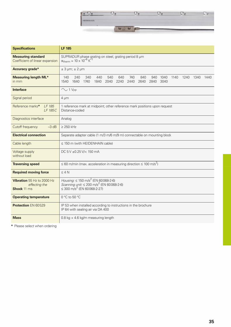
Specifi cations LF 185
Measuring standard
Coeffi cient of linear expansionSUPRADUR phase grating on steel, grating period 8 µmtherm 10 x 10–6 K–1
Accuracy grade* ± 3 µm; ± 2 µm
Measuring length ML*
in mm 140 240 340 440 540 640 740 840 940 1040 1140 1240 1340 14401540 1640 1740 1840 2040 2240 2440 2640 2840 3040
Interface 1VPP
Signal period 4 µm
Reference marks* LF 185 LF 185 C
1 reference mark at midpoint; other reference mark positions upon requestDistance-coded
Diagnostics interface Analog
Cutoff frequency –3 dB 250 kHz
Electrical connection Separate adapter cable (1 m/3 m/6 m/9 m) connectable on mounting block
Cable length 150 m (with HEIDENHAIN cable)
Voltage supply without load
DC 5 V ±0.25 V/< 150 mA
Traversing speed 60 m/min (max. acceleration in measuring direction 100 m/s2)
Required moving force 4 N
Vibration 55 Hz to 2000 Hzeffecting the
Shock 11 ms
Housing: 150 m/s2 (EN 60 068-2-6)Scanning unit: 200 m/s2 (EN 60 068-2-6) 300 m/s2 (EN 60 068-2-27)
Operating temperature 0 °C to 50 °C
Protection EN 60 529 IP 53 when installed according to instructions in the brochureIP 64 with sealing air via DA 400
Mass 0.8 kg + 4.6 kg/m measuring length
* Please select when ordering
36
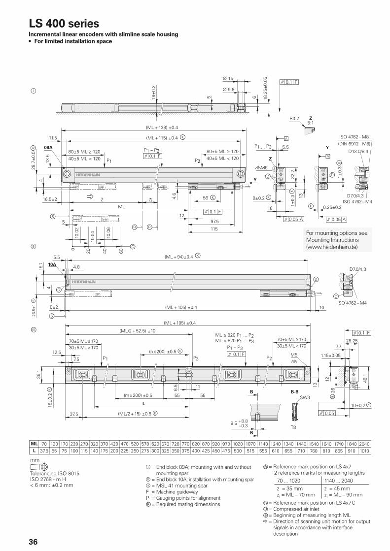
LS 400 seriesIncremental linear encoders with slimline scale housing
• For limited installation space
For mounting options see Mounting Instructions (www.heidenhain.de)
= End block09A;mountingwithandwithout mounting spar
= End block 10A; installation with mounting spar = MSL 41 mounting sparF = Machine guidewayP = Gauging points for alignmentⓀ = Required mating dimensions
Ⓡ = Reference mark position on LS 4x72 reference marks for measuring lengths70 ... 1020 1140 ... 2040z = 35 mmzi = ML – 70 mm
z = 45 mmzi = ML – 90 mm
Ⓒ = Reference mark position on LS 4x7 CⒹ = Compressed air inletⓈ = Beginning of measuring length ML = Direction of scanning unit motion for output
signals in accordance with interface description
37
LS 4x7 without mounting spar
LS 4x7 with mounting spar
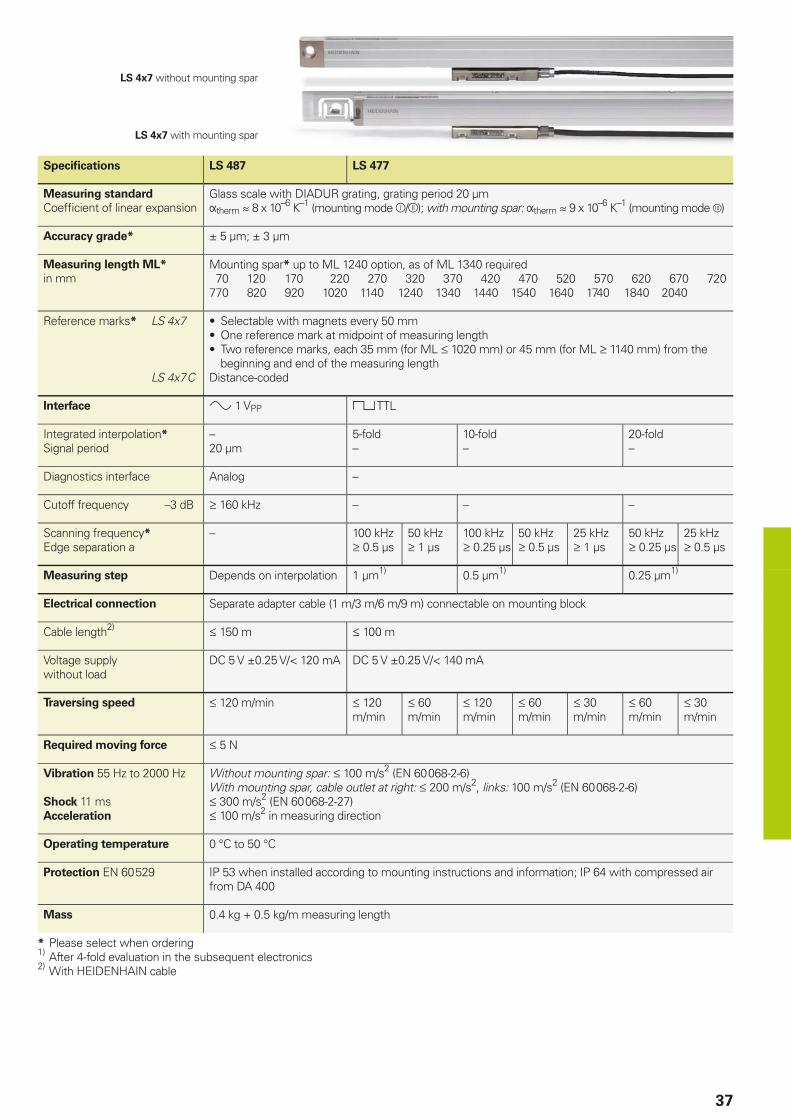
Specifi cations LS 487 LS 477
Measuring standard
Coeffi cient of linear expansionGlass scale with DIADUR grating, grating period 20 µmtherm 8 x 10⁻⁶ K–1 (mounting mode /); with mounting spar: therm 9 x 10⁻⁶ K–1 (mounting mode )
Accuracy grade* ± 5 µm; ± 3 µm
Measuring length ML*
in mmMounting spar* up to ML 1240 option, as of ML 1340 required 70 120 170 220 270 320 370 420 470 520 570 620 670 720770 820 920 1020 1140 1240 1340 1440 1540 1640 1740 1840 2040
Reference marks* LS 4x7
LS 4x7 C
• Selectable with magnets every 50 mm• One reference mark at midpoint of measuring length• Two reference marks, each 35 mm (for ML 1020 mm) or 45 mm (for ML 1140 mm) from the
beginning and end of the measuring lengthDistance-coded
Interface 1 VPP TTL
Integrated interpolation*
Signal period–20 µm
5-fold–
10-fold–
20-fold–
Diagnostics interface Analog –
Cutoff frequency –3 dB 160 kHz – – –
Scanning frequency*
Edge separation a– 100 kHz
0.5 µs50 kHz 1 µs
100 kHz 0.25 µs
50 kHz 0.5 µs
25 kHz 1 µs
50 kHz 0.25 µs
25 kHz 0.5 µs
Measuring step Depends on interpolation 1 µm1) 0.5 µm1) 0.25 µm1)
Electrical connection Separate adapter cable (1 m/3 m/6 m/9 m) connectable on mounting block
Cable length2) 150 m 100m
Voltage supply without load
DC 5 V ±0.25 V/< 120 mA DC 5 V ±0.25 V/< 140 mA
Traversing speed 120 m/min 120 m/min
60 m/min
120 m/min
60 m/min
30 m/min
60 m/min
30 m/min
Required moving force 5 N
Vibration 55 Hz to 2000 Hz
Shock 11 msAcceleration
Without mounting spar: 100 m/s2 (EN 60 068-2-6)With mounting spar, cable outlet at right: 200 m/s2, links: 100 m/s2 (EN 60 068-2-6) 300 m/s2 (EN 60 068-2-27) 100 m/s2 in measuring direction
Operating temperature 0 °C to 50 °C
Protection EN 60 529 IP 53 when installed according to mounting instructions and information; IP 64 with compressed air from DA 400
Mass 0.4 kg + 0.5 kg/m measuring length
* Please select when ordering1) After 4-fold evaluation in the subsequent electronics2) With HEIDENHAIN cable
38
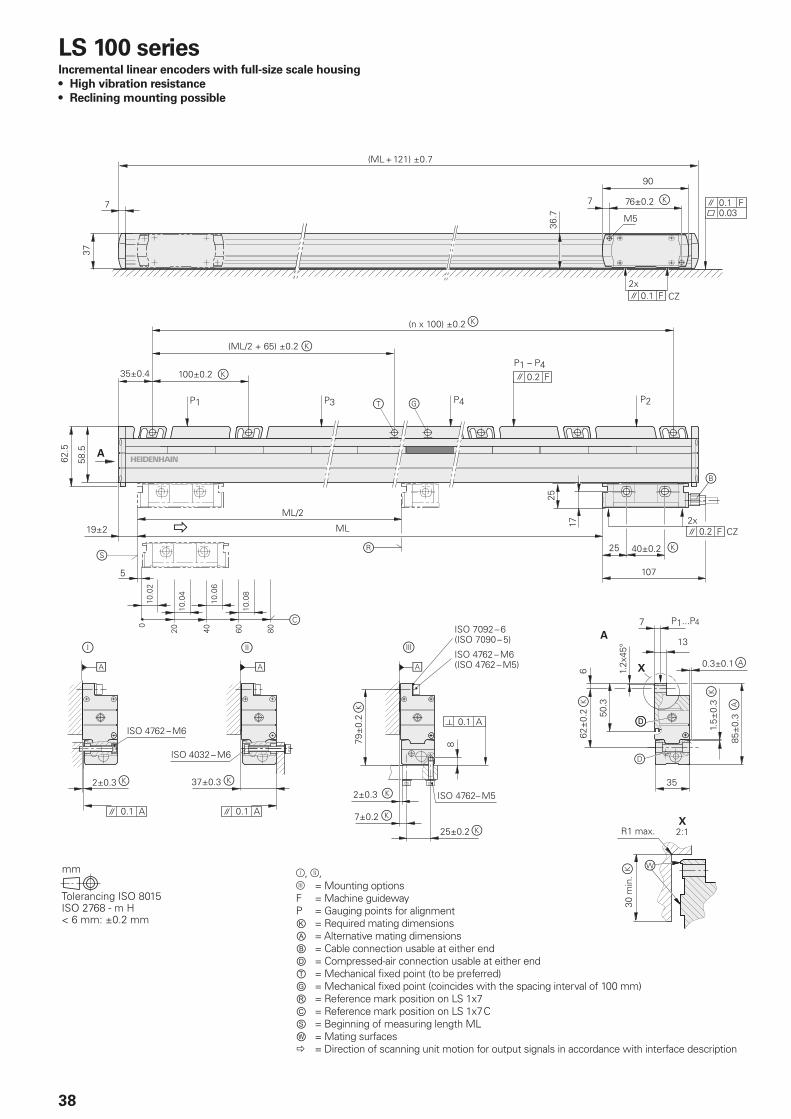
LS 100 seriesIncremental linear encoders with full-size scale housing
• High vibration resistance
• Reclining mounting possible
,, =Mounting optionsF = Machine guidewayP = Gauging points for alignmentⓀ = Required mating dimensionsⒶ = Alternative mating dimensionsⒷ = Cable connection usable at either endⒹ = Compressed-air connection usable at either endⓉ = Mechanical fi xed point (to be preferred)Ⓖ = Mechanical fi xed point (coincides with the spacing interval of 100 mm)Ⓡ = Reference mark position on LS 1x7Ⓒ = Reference mark position on LS 1x7 CⓈ =Beginningofmeasuring length MLⓌ = Mating surfaces = Direction of scanning unit motion for output signals in accordance with interface description
39
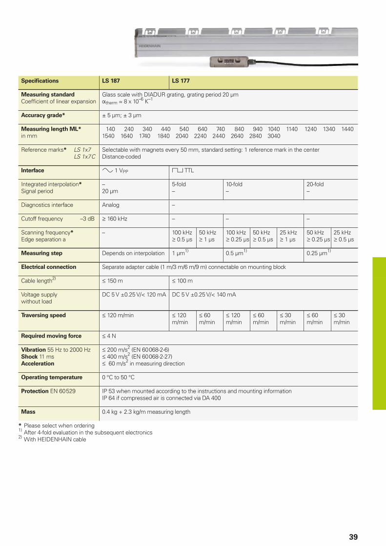
Specifi cations LS 187 LS 177
Measuring standard
Coeffi cient of linear expansionGlass scale with DIADUR grating, grating period 20 µmtherm 8 x 10⁻⁶ K–1
Accuracy grade* ± 5 µm; ± 3 µm
Measuring length ML*
in mm 140 240 340 440 540 640 740 840 940 1040 1140 1240 1340 14401540 1640 1740 1840 2040 2240 2440 2640 2840 3040
Reference marks* LS 1x7 LS 1x7 C
Selectable with magnets every 50 mm, standard setting: 1 reference mark in the centerDistance-coded
Interface 1VPP TTL
Integrated interpolation*
Signal period–20 µm
5-fold–
10-fold–
20-fold–
Diagnostics interface Analog –
Cutoff frequency –3 dB 160 kHz – – –
Scanning frequency*
Edge separation a– 100 kHz
0.5 µs50 kHz 1 µs
100 kHz 0.25 µs
50 kHz 0.5 µs
25 kHz 1 µs
50 kHz 0.25 µs
25 kHz 0.5 µs
Measuring step Depends on interpolation 1 µm1) 0.5 µm1) 0.25 µm1)
Electrical connection Separate adapter cable (1 m/3 m/6 m/9 m) connectable on mounting block
Cable length2) 150 m 100m
Voltage supply without load
DC 5 V ±0.25 V/< 120 mA DC 5 V ±0.25 V/< 140 mA
Traversing speed 120 m/min 120m/min
60m/min
120m/min
60 m/min
30 m/min
60 m/min
30 m/min
Required moving force 4 N
Vibration 55 Hz to 2000 HzShock 11 msAcceleration
200m/s2(EN60068-2-6) 400 m/s2 (EN 60 068-2-27) 60 m/s2 in measuring direction
Operating temperature 0 °C to 50 °C
Protection EN 60 529 IP 53 when mounted according to the instructions and mounting informationIP 64 if compressed air is connected via DA 400
Mass 0.4 kg + 2.3 kg/m measuring length
* Please select when ordering1) After 4-fold evaluation in the subsequent electronics2) With HEIDENHAIN cable
A
A
B
B
A-A
42.4
40
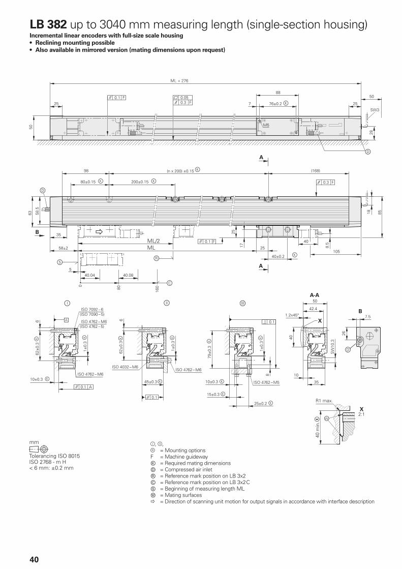
LB 382 up to 3040 mm measuring length (single-section housing)Incremental linear encoders with full-size scale housing
• Reclining mounting possible
• Also available in mirrored version (mating dimensions upon request)
,, =Mounting optionsF = Machine guidewayⓀ = Required mating dimensionsⒹ = Compressed air inletⓇ = Reference mark position on LB 3x2Ⓒ = Reference mark position on LB 3x2 CⓈ =Beginningofmeasuring length MLⓌ = Mating surfaces = Direction of scanning unit motion for output signals in accordance with interface description
41
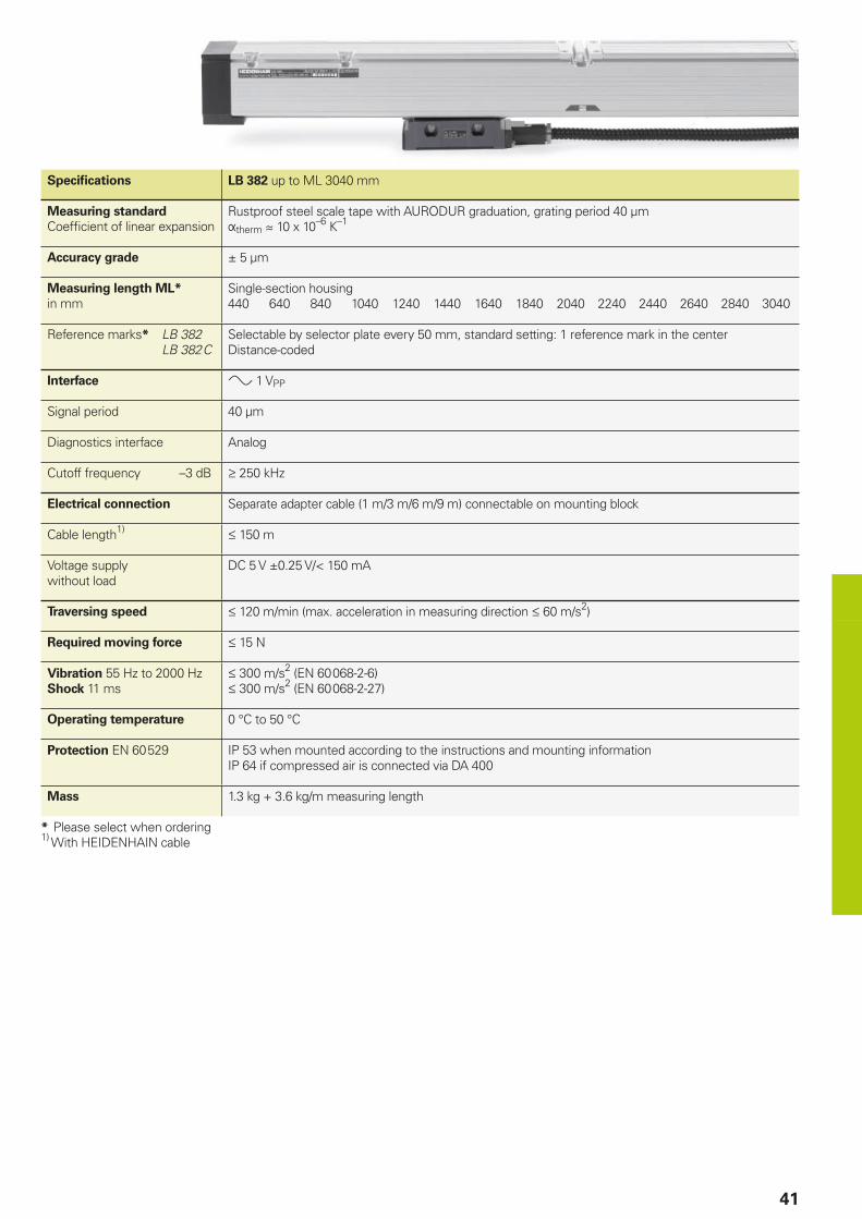
Specifi cations LB 382 up to ML 3040 mm
Measuring standard
Coeffi cient of linear expansionRustproof steel scale tape with AURODUR graduation, grating period 40 µmtherm 10 x 10–6 K–1
Accuracy grade ± 5 µm
Measuring length ML*
in mmSingle-section housing440 640 840 1040 1240 1440 1640 1840 2040 2240 2440 2640 2840 3040
Reference marks* LB 382 LB 382 C
Selectable by selector plate every 50 mm, standard setting: 1 reference mark in the centerDistance-coded
Interface 1 VPP
Signal period 40 µm
Diagnostics interface Analog
Cutoff frequency –3 dB 250 kHz
Electrical connection Separate adapter cable (1 m/3 m/6 m/9 m) connectable on mounting block
Cable length1) 150 m
Voltage supply without load
DC 5 V ±0.25 V/< 150 mA
Traversing speed 120 m/min (max. acceleration in measuring direction 60 m/s2)
Required moving force 15 N
Vibration 55 Hz to 2000 HzShock 11 ms
300m/s2(EN60068-2-6)300m/s2(EN60068-2-27)
Operating temperature 0 °C to 50 °C
Protection EN 60 529 IP 53 when mounted according to the instructions and mounting informationIP 64 if compressed air is connected via DA 400
Mass 1.3 kg + 3.6 kg/m measuring length
* Please select when ordering1) With HEIDENHAIN cable
B
A-A
B
A
A
42.4
42
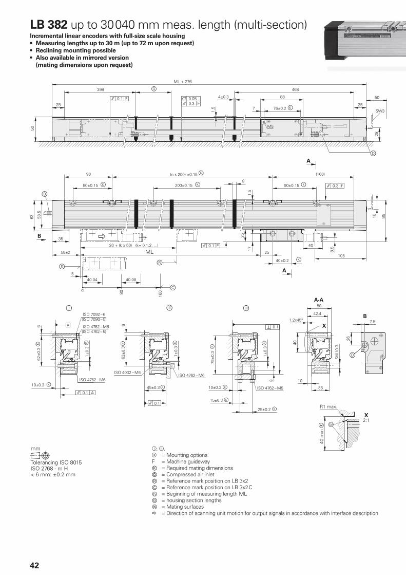
LB 382 up to 30 040 mm meas. length (multi-section)Incremental linear encoders with full-size scale housing
• Measuring lengths up to 30 m (up to 72 m upon request)
• Reclining mounting possible
• Also available in mirrored version
(mating dimensions upon request)
,, =Mounting optionsF = Machine guidewayⓀ = Required mating dimensionsⒹ = Compressed air inletⓇ = Reference mark position on LB 3x2Ⓒ = Reference mark position on LB 3x2 CⓈ =Beginningofmeasuring lengthMLⒼ = housing section lengthsⓌ = Mating surfaces = Direction of scanning unit motion for output signals in accordance with interface description
43
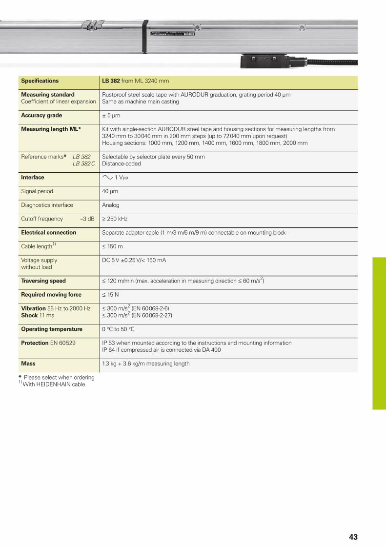
Specifi cations LB 382 from ML 3240 mm
Measuring standard
Coeffi cient of linear expansionRustproof steel scale tape with AURODUR graduation, grating period 40 µmSame as machine main casting
Accuracy grade ± 5 µm
Measuring length ML* Kit with single-section AURODUR steel tape and housing sections for measuring lengths from 3240 mm to 30 040 mm in 200 mm steps (up to 72 040 mm upon request)Housing sections: 1000 mm, 1200 mm, 1400 mm, 1600 mm, 1800 mm, 2000 mm
Reference marks* LB 382 LB 382 C
Selectable by selector plate every 50 mmDistance-coded
Interface 1VPP
Signal period 40 µm
Diagnostics interface Analog
Cutoff frequency –3 dB 250 kHz
Electrical connection Separate adapter cable (1 m/3 m/6 m/9 m) connectable on mounting block
Cable length1) 150 m
Voltage supply without load
DC 5 V ±0.25 V/< 150 mA
Traversing speed 120 m/min (max. acceleration in measuring direction 60 m/s2)
Required moving force 15 N
Vibration 55 Hz to 2000 HzShock 11 ms
300m/s2(EN60068-2-6)300m/s2(EN60068-2-27)
Operating temperature 0 °C to 50 °C
Protection EN 60 529 IP 53 when mounted according to the instructions and mounting informationIP 64 if compressed air is connected via DA 400
Mass 1.3 kg + 3.6 kg/m measuring length
* Please select when ordering1) With HEIDENHAIN cable
44
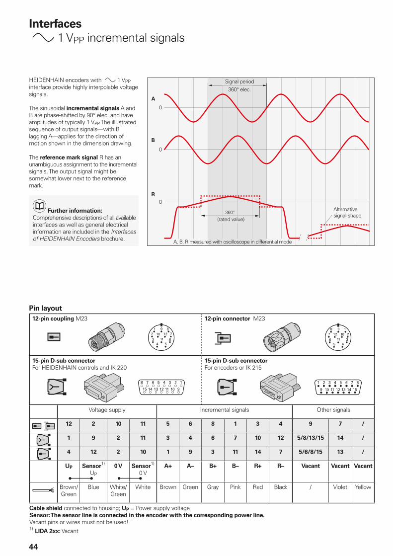
Pin layout
12-pin coupling M23 12-pin connector M23
15-pin D-sub connector
For HEIDENHAIN controls and IK 22015-pin D-sub connector
For encoders or IK 215
Voltage supply Incremental signals Other signals
12 2 10 11 5 6 8 1 3 4 9 7 /
1 9 2 11 3 4 6 7 10 12 5/8/13/15 14 /
4 12 2 10 1 9 3 11 14 7 5/6/8/15 13 /
UP Sensor1)
UP
0 V Sensor1)
0 VA+ A– B+ B– R+ R– Vacant Vacant Vacant
Brown/Green
Blue White/Green
White Brown Green Gray Pink Red Black / Violet Yellow
Cable shield connected to housing; UP = Power supply voltageSensor: The sensor line is connected in the encoder with the corresponding power line.
Vacant pins or wires must not be used!1)
LIDA 2xx: Vacant
Signal period360° elec.
(rated value)
A, B, R measured with oscilloscope in differential mode
Interfaces
1 VPP incremental signals
HEIDENHAIN encoders with 1 VPP interface provide highly interpolable voltage signals.
The sinusoidal incremental signals A and B are phase-shifted by 90° elec. and have amplitudes of typically 1 VPP. The illustrated sequence of output signals—with B lagging A—applies for the direction of motion shown in the dimension drawing.
The reference mark signal R has an unambiguous assignment to the incremental signals. The output signal might be somewhat lower next to the reference mark.
Alternative signal shape
Further information:
Comprehensive descriptions of all available interfaces as well as general electrical information are included in the Interfaces of HEIDENHAIN Encoders brochure.
45
Ele
ctr
ical co
nn
ecti
on
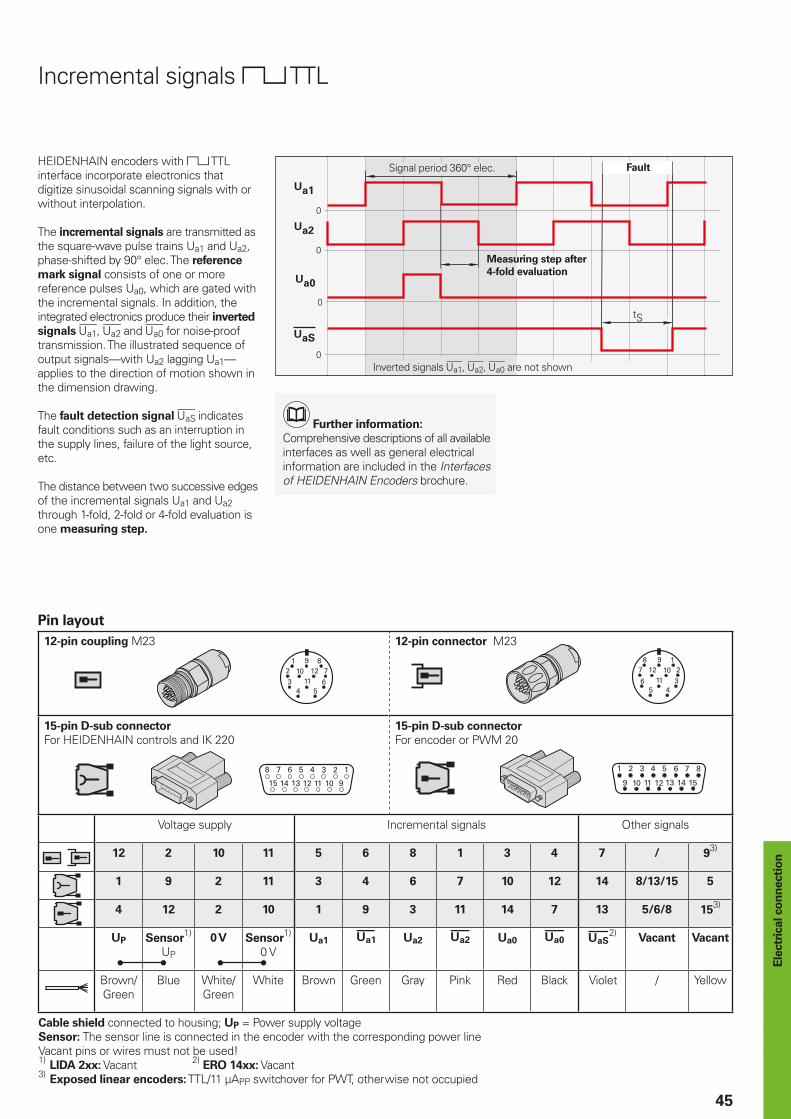
Incremental signals TTL
HEIDENHAIN encoders with TTL interface incorporate electronics that digitize sinusoidal scanning signals with or without interpolation.
The incremental signals are transmitted as the square-wave pulse trains Ua1 and Ua2, phase-shifted by 90° elec. The reference
mark signal consists of one or more reference pulses Ua0, which are gated with the incremental signals. In addition, the integrated electronics produce their inverted
signals , and for noise-proof transmission. The illustrated sequence of output signals—with Ua2 lagging Ua1—applies to the direction of motion shown in the dimension drawing.
The fault detection signal indicates fault conditions such as an interruption in the supply lines, failure of the light source, etc.
The distance between two successive edges of the incremental signals Ua1 and Ua2 through 1-fold, 2-fold or 4-fold evaluation is one measuring step.
Pin layout
12-pin coupling M23 12-pin connector M23
15-pin D-sub connector
For HEIDENHAIN controls and IK 22015-pin D-sub connector
For encoder or PWM 20
Voltage supply Incremental signals Other signals
12 2 10 11 5 6 8 1 3 4 7 / 93)
1 9 2 11 3 4 6 7 10 12 14 8/13/15 5
4 12 2 10 1 9 3 11 14 7 13 5/6/8 153)
UP Sensor1)
UP
0 V Sensor1)
0 VUa1 Ua2 Ua0 2)
Vacant Vacant
Brown/Green
Blue White/Green
White Brown Green Gray Pink Red Black Violet / Yellow
Cable shield connected to housing; UP = Power supply voltageSensor: The sensor line is connected in the encoder with the corresponding power lineVacant pins or wires must not be used!1)
LIDA 2xx: Vacant 2) ERO 14xx: Vacant
3) Exposed linear encoders: TTL/11 µAPP switchover for PWT, otherwise not occupied
Signal period 360° elec. Fault
Measuring step after
4-fold evaluation
Inverted signals , , are not shown
Further information:
Comprehensive descriptions of all available interfaces as well as general electrical information are included in the Interfaces of HEIDENHAIN Encoders brochure.
46
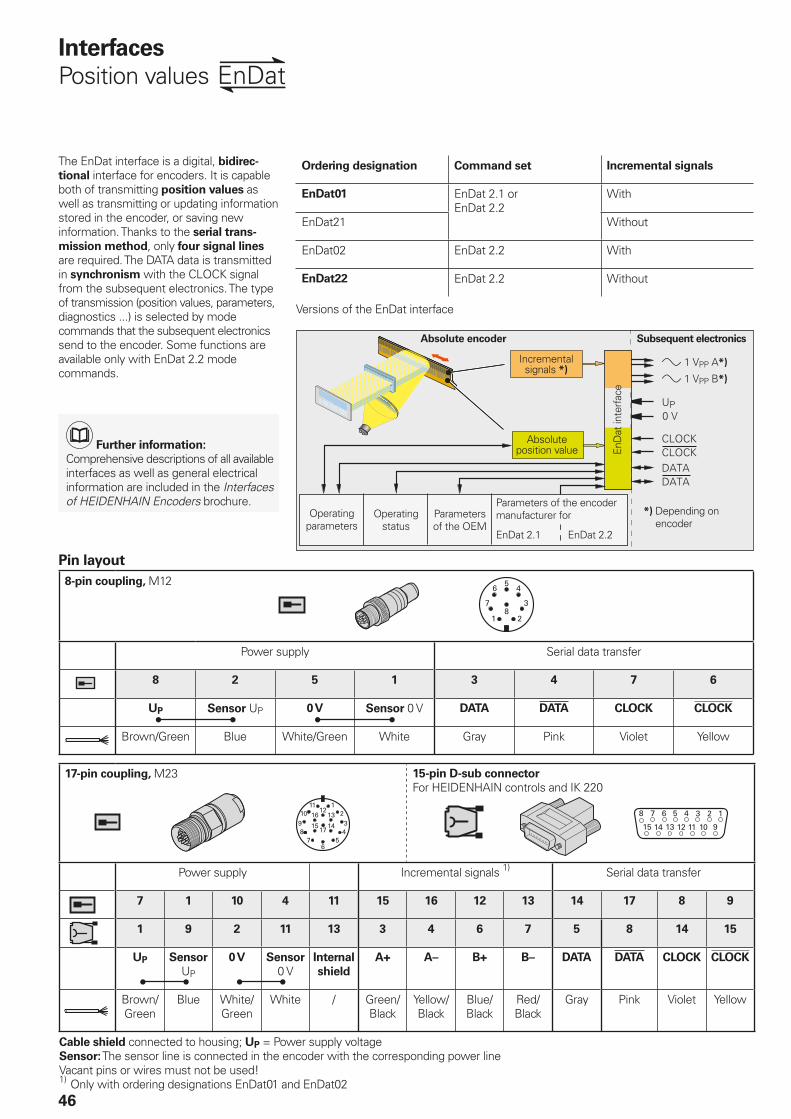
Pin layout
8-pin coupling, M12
Power supply Serial data transfer
8 2 5 1 3 4 7 6
UP Sensor UP 0 V Sensor 0 V DATA DATA CLOCK CLOCK
Brown/Green Blue White/Green White Gray Pink Violet Yellow
17-pin coupling, M23 15-pin D-sub connector
For HEIDENHAIN controls and IK 220
Power supply Incremental signals 1) Serial data transfer
7 1 10 4 11 15 16 12 13 14 17 8 9
1 9 2 11 13 3 4 6 7 5 8 14 15
UP Sensor
UP
0 V Sensor
0 VInternal
shield
A+ A– B+ B– DATA DATA CLOCK CLOCK
Brown/Green
Blue White/Green
White / Green/Black
Yellow/Black
Blue/Black
Red/Black
Gray Pink Violet Yellow
Cable shield connected to housing; UP = Power supply voltageSensor: The sensor line is connected in the encoder with the corresponding power lineVacant pins or wires must not be used!1)
Only with ordering designations EnDat01 and EnDat02
Interfaces
Position values
The EnDat interface is a digital, bidirec-
tional interface for encoders. It is capable both of transmitting position values as well as transmitting or updating information stored in the encoder, or saving new information. Thanks to the serial trans-
mission method, only four signal lines are required. The DATA data is transmitted in synchronism with the CLOCK signal from the subsequent electronics. The type of transmission (position values, parameters, diagnostics ...) is selected by mode commands that the subsequent electronics send to the encoder. Some functions are available only with EnDat 2.2 mode commands.
Ordering designation Command set Incremental signals
EnDat01 EnDat 2.1 or EnDat 2.2
With
EnDat21 Without
EnDat02 EnDat 2.2 With
EnDat22 EnDat 2.2 Without
Versions of the EnDat interface
Absolute encoder Subsequent electronics
1VPPA*)
1VPPB*)
Operating parameters
Operating status
Parameters of the OEM
Parameters of the encoder manufacturer for
EnDat 2.1 EnDat 2.2
*) Depending on encoder
Absolute position value En
Dat
inte
rfac
e
Incremental signals *)
Further information:
Comprehensive descriptions of all available interfaces as well as general electrical information are included in the Interfaces of HEIDENHAIN Encoders brochure.
47
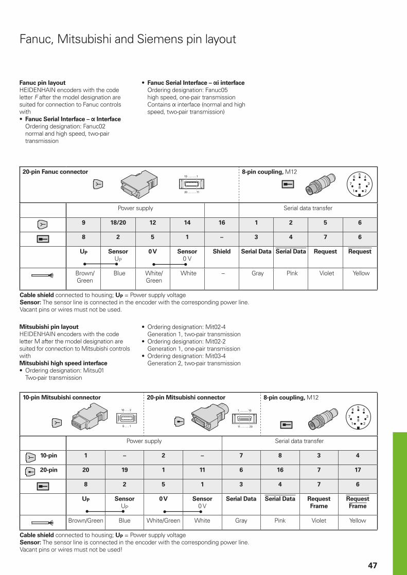
20-pin Fanuc connector 8-pin coupling, M12
Power supply Serial data transfer
9 18/20 12 14 16 1 2 5 6
8 2 5 1 – 3 4 7 6
UP Sensor
UP
0 V Sensor
0 VShield Serial Data Serial Data Request Request
Brown/Green
Blue White/Green
White – Gray Pink Violet Yellow
Cable shield connected to housing; UP = Power supply voltageSensor: The sensor line is connected in the encoder with the corresponding power line.Vacant pins or wires must not be used.
Fanuc pin layout
HEIDENHAIN encoders with the code letter F after the model designation are suited for connection to Fanuc controls with• Fanuc Serial Interface – Interface
Ordering designation: Fanuc02 , two-pair transmission
Fanuc, Mitsubishi and Siemens pin layout
Mitsubishi pin layout
HEIDENHAIN encoders with the code letter M after the model designation are suited for connection to Mitsubishi controls withMitsubishi high speed interface
• Ordering designation: Mitsu01 Two-pair transmission
10-pin Mitsubishi connector 20-pin Mitsubishi connector 8-pin coupling, M12
Power supply Serial data transfer
10-pin 1 – 2 – 7 8 3 4
20-pin 20 19 1 11 6 16 7 17
8 2 5 1 3 4 7 6
UP Sensor
UP
0 V Sensor
0 VSerial Data Serial Data Request
Frame
Request
Frame
Brown/Green Blue White/Green White Gray Pink Violet Yellow
Cable shield connected to housing; UP = Power supply voltageSensor: The sensor line is connected in the encoder with the corresponding power line.Vacant pins or wires must not be used!
• Fanuc Serial Interface – i interface
Ordering designation: Fanuc05high speed, one-pair transmissionContains interface (normal and high speed, two-pair transmission)
• Ordering designation: Mit02-4 Generation 1, two-pair transmission
• Ordering designation: Mit02-2 Generation 1, one-pair transmission
• Ordering designation: Mit03-4 Generation 2, two-pair transmission
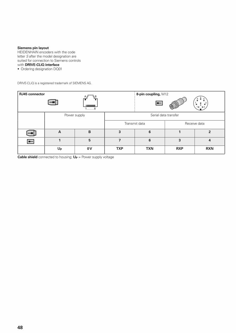
48
RJ45 connector 8-pin coupling, M12
Power supply Serial data transfer
Transmit data Receive data
A B 3 6 1 2
1 5 7 6 3 4
UP 0 V TXP TXN RXP RXN
Cable shield connected to housing; UP = Power supply voltage
Siemens pin layout
HEIDENHAIN encoders with the code letter S after the model designation are suited for connection to Siemens controls with DRIVE-CLiQ interface
• Ordering designation DQ01
DRIVE-CLiQ is a registered trademark of SIEMENS AG.
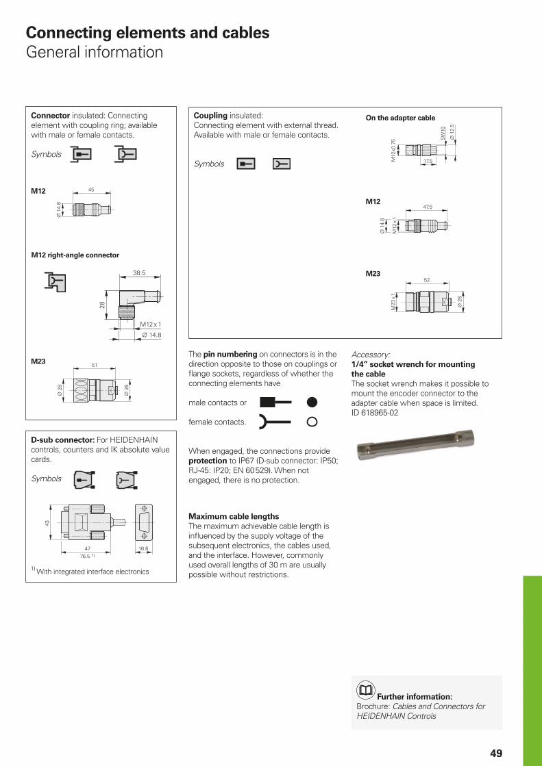
M23
M12
M23
M12
49
The pin numbering on connectors is in the direction opposite to those on couplings or fl ange sockets, regardless of whether the connecting elements have
male contacts or
female contacts.
When engaged, the connections provide protection to IP67 (D-sub connector: IP50; RJ-45: IP20; EN 60 529). When not engaged, there is no protection.
Connecting elements and cables
General information
Connector insulated: Connecting element with coupling ring; available with male or female contacts.
Symbols
Coupling insulated: Connecting element with external thread. Available with male or female contacts.
Symbols
D-sub connector: For HEIDENHAIN controls, counters and IK absolute value cards.
Symbols
1) With integrated interface electronics
On the adapter cable
Accessory:1/4” socket wrench for mounting
the cable
The socket wrench makes it possible to mount the encoder connector to the adapter cable when space is limited.ID 618965-02
M12 right-angle connector
Maximum cable lengths
The maximum achievable cable length is infl uenced by the supply voltage of the subsequent electronics, the cables used, and the interface. However, commonly used overall lengths of 30 m are usually possible without restrictions.
Further information:
Brochure: Cables and Connectors for HEIDENHAIN Controls
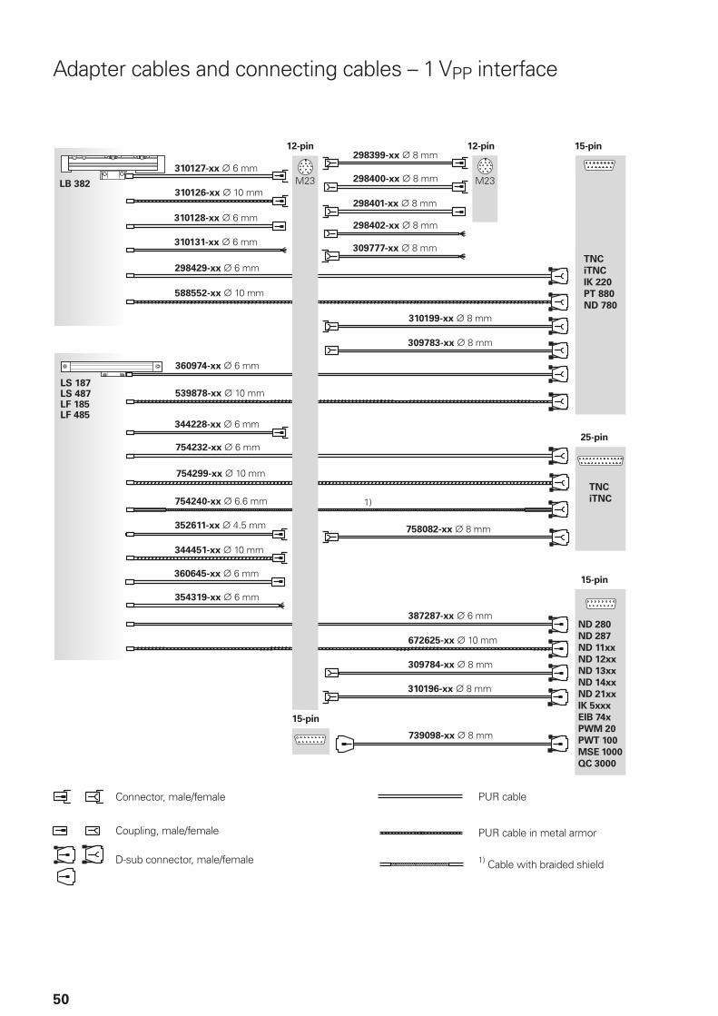
50
Adapter cables and connecting cables – 1 VPP interface
12-pin 12-pin 15-pin
25-pin
15-pin
15-pin
Connector, male/female
Coupling, male/female
D-sub connector, male/female
PUR cable
PUR cable in metal armor
1) Cable with braided shield
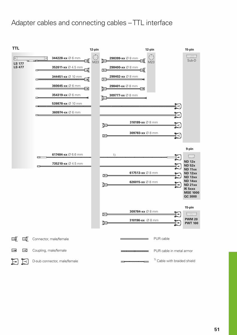
51
12-pin 12-pin 15-pin
9-pin
15-pin
Connector, male/female
Coupling, male/female
D-sub connector, male/female
PUR cable
PUR cable in metal armor
1) Cable with braided shield
Adapter cables and connecting cables – TTL interface
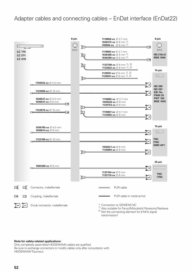
52
Adapter cables and connecting cables – EnDat interface (EnDat22)
Connector, male/female
Coupling, male/female
D-sub connector, male/female
PUR cable
PUR cable in metal armor
* Connection to SIEMENS NC1) Also suitable for Fanuc/Mitsubishi/ Panasonic/Yaskawa2) Not the connecting element for 8 MHz signal
transmission!
8-pin 8-pin
15-pin
15-pin
25-pin
Note for safety-related applications: Only completely assembled HEIDENHAIN cables are qualifi ed. Be sure to exchange connectors or modify cables only after consultation with HEIDENHAIN Traunreut.
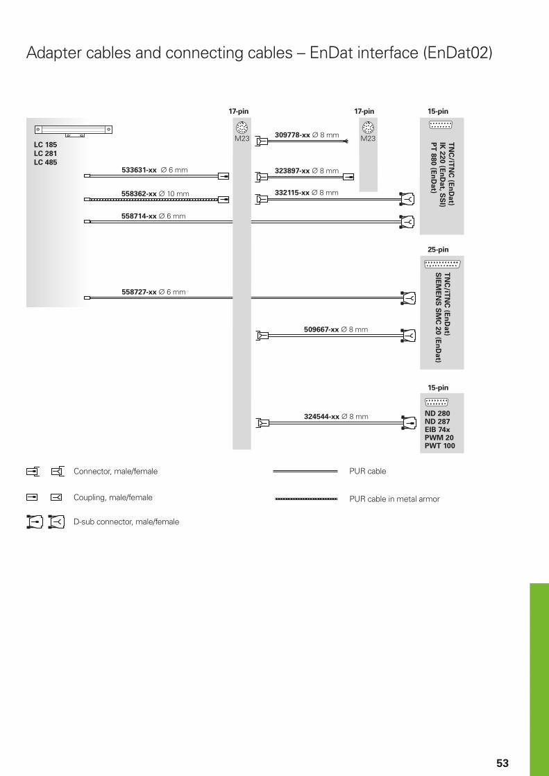
53
Adapter cables and connecting cables – EnDat interface (EnDat02)
Connector, male/female
Coupling, male/female
D-sub connector, male/female
PUR cable
PUR cable in metal armor
17-pin 17-pin 15-pin
25-pin
15-pin
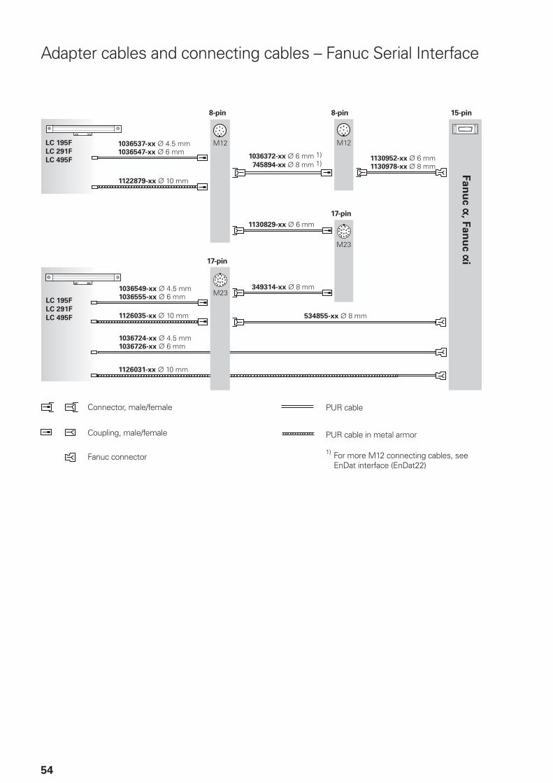
54
Adapter cables and connecting cables – Fanuc Serial Interface
Connector, male/female
Coupling, male/female
Fanuc connector
PUR cable
PUR cable in metal armor
1) For more M12 connecting cables, see EnDat interface (EnDat22)
8-pin 15-pin8-pin
17-pin
17-pin
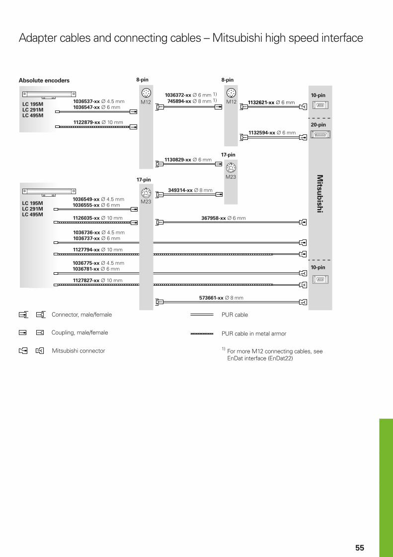
55
Adapter cables and connecting cables – Mitsubishi high speed interface
Connector, male/female
Coupling, male/female
Mitsubishi connector
PUR cable
8-pin
10-pin
20-pin
10-pin
8-pin
17-pin
17-pin
Absolute encoders
PUR cable in metal armor
1) For more M12 connecting cables, see EnDat interface (EnDat22)
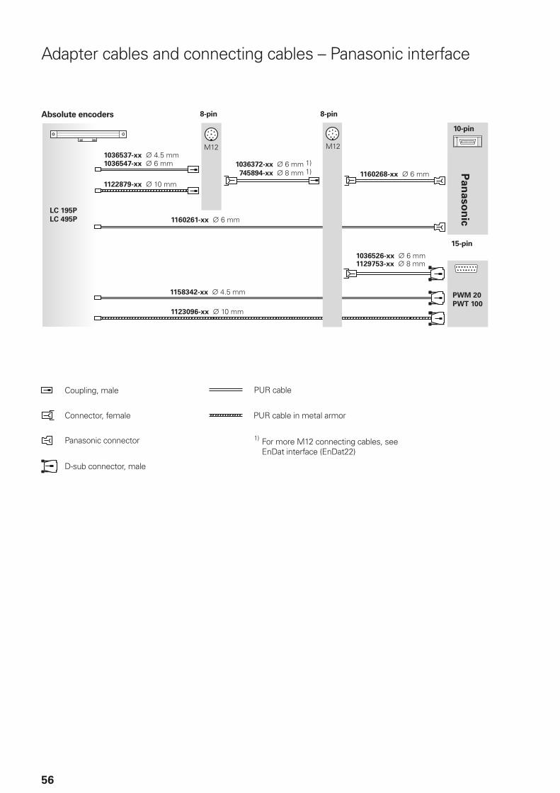
56
Adapter cables and connecting cables – Panasonic interface
Connector, female
Coupling, male
Panasonic connector
PUR cable
PUR cable in metal armor
1) For more M12 connecting cables, see EnDat interface (EnDat22)
8-pin
10-pin
8-pinAbsolute encoders
15-pin
D-sub connector, male
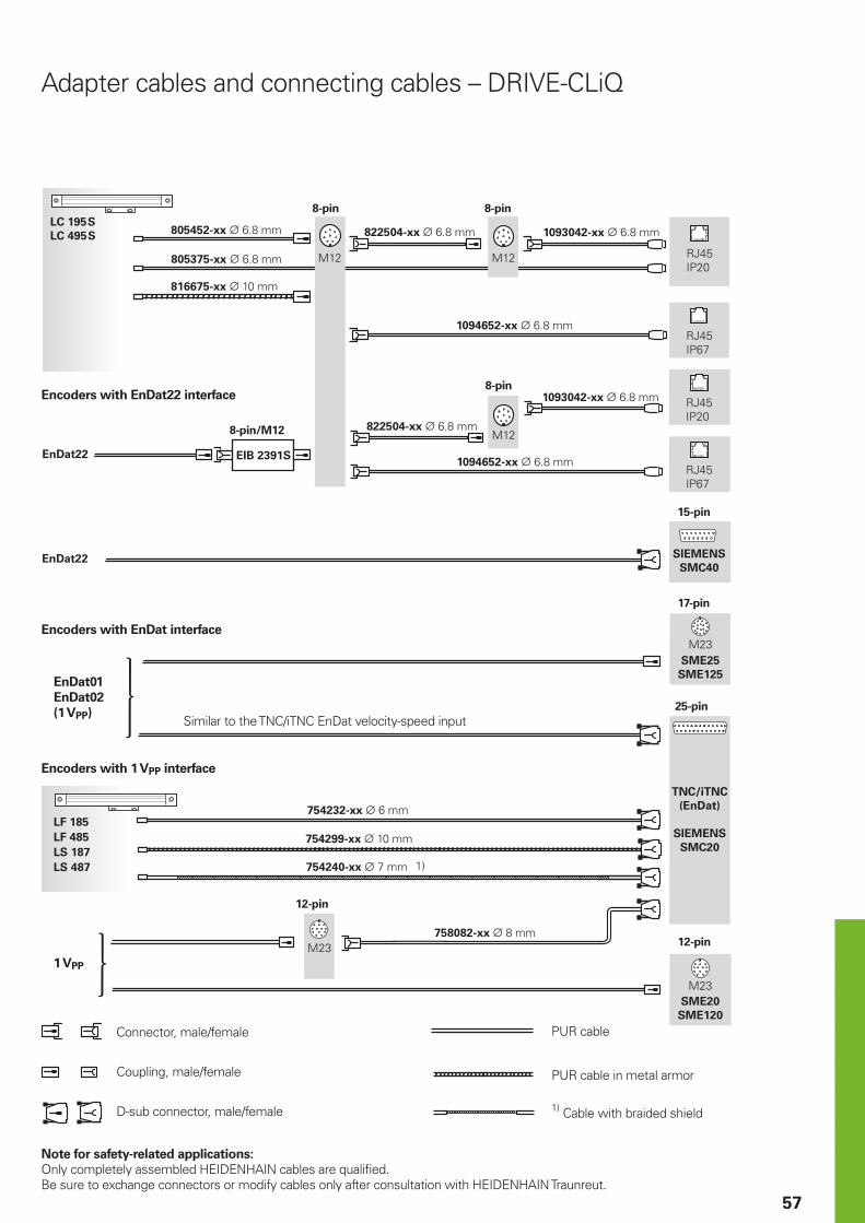
57
Adapter cables and connecting cables – DRIVE-CLiQ
Connector, male/female
Coupling, male/female
D-sub connector, male/female
PUR cable
8-pin
8-pin/M12
15-pin
8-pin
8-pin
PUR cable in metal armor
1) Cable with braided shield
17-pin
25-pin
12-pin
12-pin
Encoders with EnDat interface
Encoders with EnDat22 interface
EnDat01
EnDat02
(1 VPP)
Encoders with 1 VPP interface
Similar to the TNC/iTNC EnDat velocity-speed input
1 VPP
Note for safety-related applications: Only completely assembled HEIDENHAIN cables are qualifi ed. Be sure to exchange connectors or modify cables only after consultation with HEIDENHAIN Traunreut.
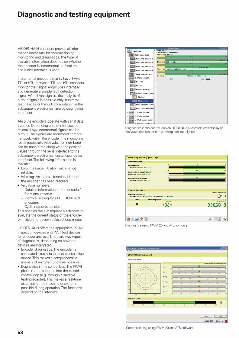
58
Diagnostic and testing equipment
Diagnostics using PWM 20 and ATS software
HEIDENHAIN encoders provide all infor-mation necessary for commissioning, monitoring and diagnostics. The type of available information depends on whether the encoder is incremental or absolute and which interface is used.
Incremental encoders mainly have 1 VPP, TTL or HTL interfaces. TTL and HTL encoders monitor their signal amplitudes internally and generate a simple fault detection signal. With 1 VPP signals, the analysis of output signals is possible only in external test devices or through computation in the subsequent electronics (analog diagnostics interface).
Absolute encoders operate with serial data transfer. Depending on the interface, ad-ditional 1 VPP incremental signals can be output. The signals are monitored compre-hensively within the encoder. The monitoring result (especially with valuation numbers) can be transferred along with the position values through the serial interface to the subsequent electronics (digital diagnostics interface). The following information is available:• Error message: Position value is not
reliable.• Warning: An internal functional limit of
the encoder has been reached• Valuation numbers:
– Detailed information on the encoder’s functional reserve
– Identical scaling for all HEIDENHAIN encoders
– Cyclic output is possibleThis enables the subsequent electronics to evaluate the current status of the encoder with little effort even in closed-loop mode.
HEIDENHAIN offers the appropriate PWM inspection devices and PWT test devices for encoder analysis. There are two types of diagnostics, depending on how the devices are integrated:• Encoder diagnostics: The encoder is
connected directly to the test or inspection device. This makes a comprehensive analysis of encoder functions possible.
• Diagnostics in the control loop: The PWM phase meter is looped into the closed control loop (e.g. through a suitable testing adapter). This makes a real-time diagnosis of the machine or system possible during operation. The functions depend on the interface.
Commissioning using PWM 20 and ATS software
Diagnostics in the control loop on HEIDENHAIN controls with display of the valuation number or the analog encoder signals
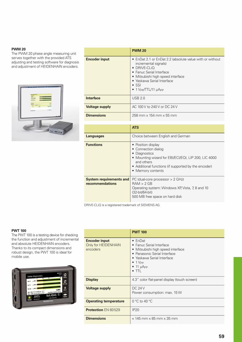
59
PWM 20
The PWM 20 phase angle measuring unit serves together with the provided ATS adjusting and testing software for diagnosis and adjustment of HEIDENHAIN encoders.
PWM 20
Encoder input • EnDat 2.1 or EnDat 2.2 (absolute value with or without incremental signals)
• DRIVE-CLiQ• Fanuc Serial Interface• Mitsubishi high speed interface• Yaskawa Serial Interface• SSI• 1 VPP/TTL/11 µAPP
Interface USB 2.0
Voltage supply AC 100 V to 240 V or DC 24 V
Dimensions 258 mm x 154 mm x 55 mm
ATS
Languages Choice between English and German
Functions • Position display• Connection dialog• Diagnostics• Mounting wizard for EBI/ECI/EQI, LIP 200, LIC 4000
and others• Additional functions (if supported by the encoder)• Memory contents
System requirements and
recommendations
PC (dual-core processor > 2 GHz)RAM > 2 GBOperating system: Windows XP, Vista, 7, 8 and 10 (32-bit/64-bit)500 MB free space on hard disk
DRIVE-CLiQ is a registered trademark of SIEMENS AG.
PWT 100
The PWT 100 is a testing device for checking the function and adjustment of incremental and absolute HEIDENHAIN encoders. Thanks to its compact dimensions and robust design, the PWT 100 is ideal for mobile use.
PWT 100
Encoder input
Only for HEIDENHAIN encoders
• EnDat• Fanuc Serial Interface• Mitsubishi high speed interface• Panasonic Serial Interface• Yaskawa Serial Interface• 1 VPP• 11 µAPP• TTL
Display 4.3” color fl at-panel display (touch screen)
Voltage supply DC 24 VPower consumption: max. 15 W
Operating temperature 0 °C to 40 °C
Protection EN 60 529 IP20
Dimensions 145 mm x 85 mm x 35 mm
PL APS02-384 Warszawa, Polandwww.heidenhain.pl
PT FARRESA ELECTRÓNICA, LDA.4470 - 177 Maia, Portugalwww.farresa.pt
RO HEIDENHAIN Reprezentanta RomaniaBrasov, 500407, Romaniawww.heidenhain.ro
RS Serbia BG
RU OOO HEIDENHAIN115172 Moscow, Russiawww.heidenhain.ru
SE HEIDENHAIN Scandinavia AB12739 Skärholmen, Swedenwww.heidenhain.se
SG HEIDENHAIN PACIFIC PTE LTDSingapore 408593www.heidenhain.com.sg
SK KOPRETINA TN s.r.o.91101 Trencin, Slovakiawww.kopretina.sk
SL NAVO d.o.o.2000 Maribor, Sloveniawww.heidenhain.si
TH HEIDENHAIN (THAILAND) LTDBangkok 10250, Thailandwww.heidenhain.co.th
TR T&M Mühendislik San. ve Tic. LTD. STI·.
34775 Y. Dudullu – Ümraniye-Istanbul, Turkeywww.heidenhain.com.tr
TW HEIDENHAIN Co., Ltd.Taichung 40768, Taiwan R.O.C.www.heidenhain.com.tw
UA Gertner Service GmbH Büro Kiev 01133 Kiev, Ukrainewww.heidenhain.ua
US HEIDENHAIN CORPORATIONSchaumburg, IL 60173-5337, USAwww.heidenhain.com
VE Maquinaria Diekmann S.A. Caracas, 1040-A, VenezuelaE-mail: [email protected]
VN AMS Co. LtdHCM City, VietnamE-mail: [email protected]
ZA MAFEMA SALES SERVICES C.C.Midrand 1685, South Africawww.heidenhain.co.za
ES FARRESA ELECTRONICA S.A.08028 Barcelona, Spainwww.farresa.es
FI HEIDENHAIN Scandinavia AB01740 Vantaa, Finlandwww.heidenhain.fi
FR HEIDENHAIN FRANCE sarl92310 Sèvres, Francewww.heidenhain.fr
GB HEIDENHAIN (G.B.) LimitedBurgess Hill RH15 9RD, United Kingdomwww.heidenhain.co.uk
GR MB Milionis Vassilis17341 Athens, Greecewww.heidenhain.gr
HK HEIDENHAIN LTDKowloon, Hong KongE-mail: [email protected]
HR Croatia SL
HU HEIDENHAIN Kereskedelmi Képviselet1239 Budapest, Hungarywww.heidenhain.hu
ID PT Servitama Era ToolsindoJakarta 13930, IndonesiaE-mail: [email protected]
IL NEUMO VARGUS MARKETING LTD.Tel Aviv 61570, IsraelE-mail: [email protected]
IN HEIDENHAIN Optics & ElectronicsIndia Private LimitedChetpet, Chennai 600 031, Indiawww.heidenhain.in
IT HEIDENHAIN ITALIANA S.r.l.20128 Milano, Italywww.heidenhain.it
JP HEIDENHAIN K.K.Tokyo 102-0083, Japanwww.heidenhain.co.jp
KR HEIDENHAIN Korea LTD.Gasan-Dong, Seoul, Korea 153-782www.heidenhain.co.kr
MX HEIDENHAIN CORPORATION MEXICO20290 Aguascalientes, AGS., MexicoE-mail: [email protected]
MY ISOSERVE SDN. BHD.43200 Balakong, SelangorE-mail: [email protected]
NL HEIDENHAIN NEDERLAND B.V.6716 BM Ede, Netherlandswww.heidenhain.nl
NO HEIDENHAIN Scandinavia AB7300 Orkanger, Norwaywww.heidenhain.no
PH MACHINEBANKS' CORPORATIONQuezon City, Philippines 1113E-mail: [email protected]
AR NAKASE SRL.B1653AOX Villa Ballester, Argentinawww.heidenhain.com.ar
AT HEIDENHAIN Techn. Büro Österreich83301 Traunreut, Germanywww.heidenhain.de
AU FCR MOTION TECHNOLOGY PTY LTD3026 Victoria, AustraliaE-mail: [email protected]
BE HEIDENHAIN NV/SA1760 Roosdaal, Belgiumwww.heidenhain.be
BG ESD Bulgaria Ltd.Sofi a 1172, Bulgariawww.esd.bg
BR DIADUR Indústria e Comércio Ltda.04763-070 – São Paulo – SP, Brazilwww.heidenhain.com.br
BY GERTNER Service GmbH220026 Minsk, Belaruswww.heidenhain.by
CA HEIDENHAIN CORPORATIONMississauga, OntarioL5T2N2, Canadawww.heidenhain.com
CH HEIDENHAIN (SCHWEIZ) AG8603 Schwerzenbach, Switzerlandwww.heidenhain.ch
CN DR. JOHANNES HEIDENHAIN (CHINA) Co., Ltd.Beijing 101312, Chinawww.heidenhain.com.cn
CZ HEIDENHAIN s.r.o.102 00 Praha 10, Czech Republicwww.heidenhain.cz
DK TP TEKNIK A/S2670 Greve, Denmarkwww.tp-gruppen.dk
DE HEIDENHAIN Vertrieb Deutschland83301 Traunreut, Deutschland 08669 31-3132 08669 32-3132E-Mail: [email protected]
HEIDENHAIN Technisches Büro Nord12681 Berlin, Deutschland 030 54705-240
HEIDENHAIN Technisches Büro Mitte07751 Jena, Deutschland 03641 4728-250
HEIDENHAIN Technisches Büro West44379 Dortmund, Deutschland 0231 618083-0
HEIDENHAIN Technisches Büro Südwest70771 Leinfelden-Echterdingen, Deutschland 0711 993395-0
HEIDENHAIN Technisches Büro Südost83301 Traunreut, Deutschland 08669 31-1345
Vollständige und weitere Adressen siehe www.heidenhain.deFor complete and further addresses see www.heidenhain.de
������������ ��� ��������������� ��������������������������������������� �������������� �������������������� !��"�#����������
������ !���� ��!�
571470-2B · 10 · 6/2017 · H · Printed in Germany