liquid sloshing in elastic containers - nasa sloshing in elastic containers by helmut f. rauer,...
TRANSCRIPT

NASA CONTRACTOR
REPORT
LIQUID SLOSHING IN ELASTIC CONTAINERS
by Helmut F. Rauer, T’eh-Min Hsu, and James Ting-Shun Wang
Prepared by
GEORGIA INSTITUTE OF TECHNOLOGY
Atlanta, Ga.
f Or
NATIONAL AERONAUTICS AND SPACE ADMINISTRATION l WASHINGTON, D. C. l SEPTEMBER 1967
https://ntrs.nasa.gov/search.jsp?R=19670026429 2018-05-26T02:16:04+00:00Z
TECH LIBRARY KAFB. NM
llObO223 NASA CR-882
LIQUID SLOSHING IN ELASTIC CONTAINERS
By Helmut F. Bauer, Teh-Min Hsu, and James Ting-Shun Wang
Distribution of this report is provided in the interest of information exchange. Responsibility for the contents resides in the author or organization that prepared it.
Prepared by Originator under Project B-906
Prepared under Grant No. NGR-11-002-028 by GEORGIA INSTITUTE OF TECHNOLOGY
Atlanta, Ga.
for
NATIONAL AERONAUTICS AND SPACE ADMINISTRATION
For sale by the Clearinghouse for Federal Scientific and Technical Information
Springfield, Virginia 22151 - CFSTI price $3.00

ABSTRACT
The coupled oscillations of containers , partially filled with an
inviscid and incompressible liquid, are investigated. The following container
configurations are considered: (1) a long, rectangular tank with an elastic
bottom, (2) a long, rectangular tank with elastic walls, and (3) a cylin-
drical tank with an elastic wall. Linear theories are used for the descrip-
tion of the motion of the fluid, and that of the container. Numerical values
of the natural frequencies are presented for various liquid heights and tank
configurations.
iii

D
E
P
t
W
xsy,=
cp
UJ
V
of
P
Sk,
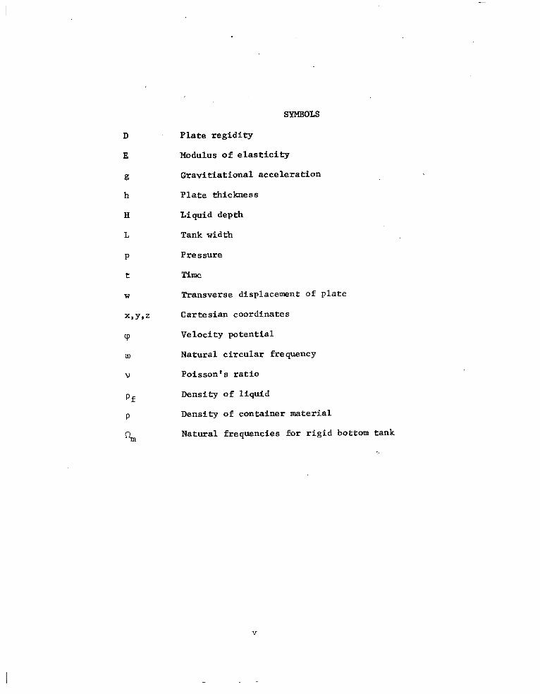
SYMBOLS
Plate regidity
Modulus of elasticity
Gravitiational acceleration
Plate thickness
Liquid depth
Tank width
Pressure
Time
Transverse displacement of plate
Cartesian coordinates
Velocity potential
Natural circular frequency
Poisson's ratio
Density of liquid
Density of container material
Natural frequencies for rigid bottom tank
V
IN'IRODUCTION
Numerous authors have used linear and non-linear theories in studies
of liquid oscillations in rigid containers. However, work involving coupled
oscillations of liquid and elastic containers, is quite limited. Miles [l]
accounted for the flexibility of the tank by considering specific natural
wdes of the tank. Bleich [2] used approximate methods to include the
elastic properties of the bottom of the tank and obtained a solution which
is valid for large depths of liquid. Bhuta and Koval [3] accounted for the
flexibility of the bottom by treating it as a membrane. Sielanann and Chang [4]
calculated the natural frequencies of a liquid in a cylindrical tank with
elastic bottom, by using a method similar to that of Bhuta and Koval.
Huang [S] and [6] studied the longitudinal sloshing of a liquid in an elas-
tic, hemispherical tank, with contradictory results. Coale and Nagano [7]
presented an approximate solution for the axisymnetric modes of an elastic
cylindrical-hemispherical tank, partially filled with liquid. Only membrane
theory is used for the tank and some boundary conditions are not completely
satisfied,
The present study is concerned with the coupled oscillation of a long,
elastic, rectangular tank, and a cylindrical tank with elastic wall, both
partially filled with liqujd. The.analyses of the containers are based on
bending theory.
1
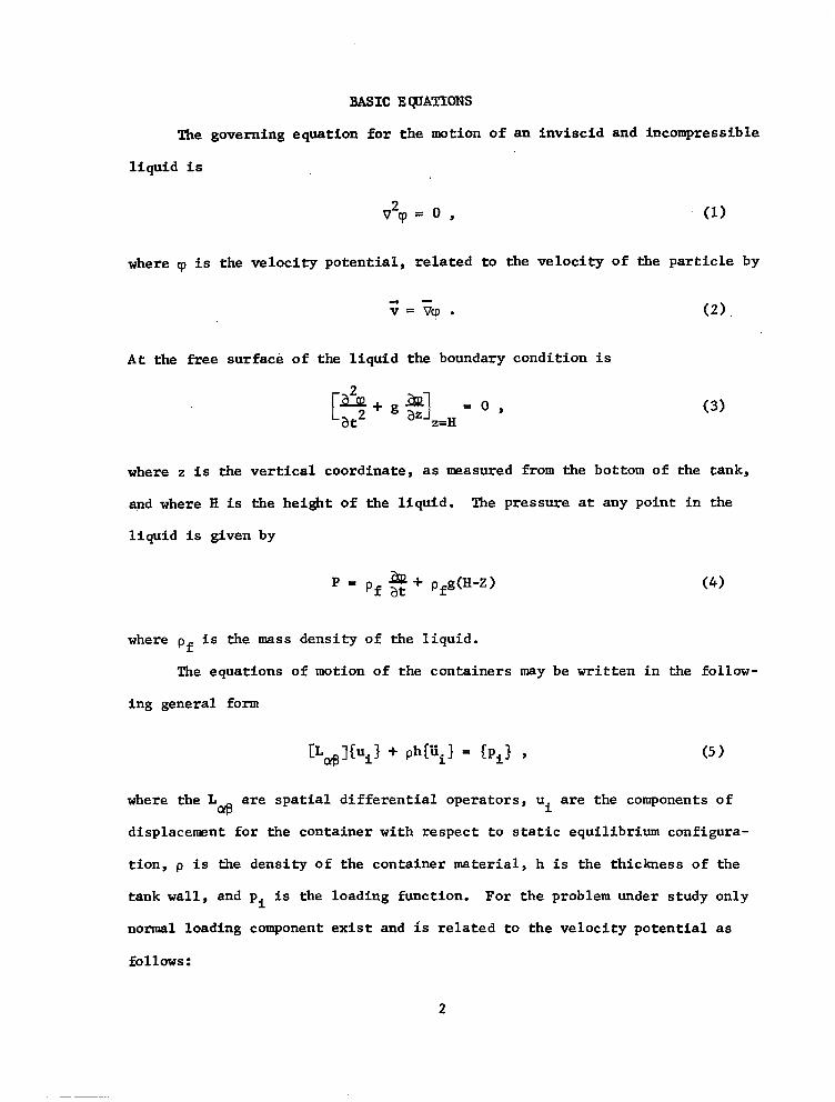
BASIC EQUATIONS
The governing equation for the motion of an inviscid and incompressible
liquid is
v2cp = 0 , (1)
where CJI is the velocity potential, related to the velocity of the particle by
-4 v=&l. (2).
At the free surface of the liquid the boundary condition is
[ i&L a21 at2 + g 82 z=H = O ’ (3)
where z is the vertical coordinate, as lneasured from the bottom of the tank,
and where H is the height of the liquid. The pressure at any point in the
liquid is given by
P a+ = of at pfgow (4)
where pf is the mass density of the liquid.
The equations of motion of the containers may be written in the follow-
ing general form
[L,]CU,~ + phf'i} = CP,3 Y (5)
where the L Q@
are spatial differential operators, ui are the components of
displacement for the container with respect to static equilibrium configura-
tion, p is the density of the container material, h is the thickness of the
tank wall, and pi is the loading function. For the problem under study only
normal loading component exist and is related to the velocity potential as
follows:
2
I -
pi = I at the interface of liquid and tank.
Equation (5) couples the liquid velocity potential cp and the container dis-
placements ui.
As usual, harmonic motion is assumed for the system. The general
solutions for cp and ui are then obtained by solving the coupled differ-
ential equations (1) and (5) in conjunction with the condition, equation (3),
at the free surface of the liquid. The requirement of compatible motion of
liquid and container then results in the frequency equation. An iterative
procedure is used to obtain the numerical values for the natural frequencies.
3

LGNGBECTANGULARTANKWITHE~S!!!IC BO!l!lUM
In Cartesian coordinates the motion of an inviscid and incompressible
liquid is governed by
&+&+& 0. ax2 ay2 az2
(1)
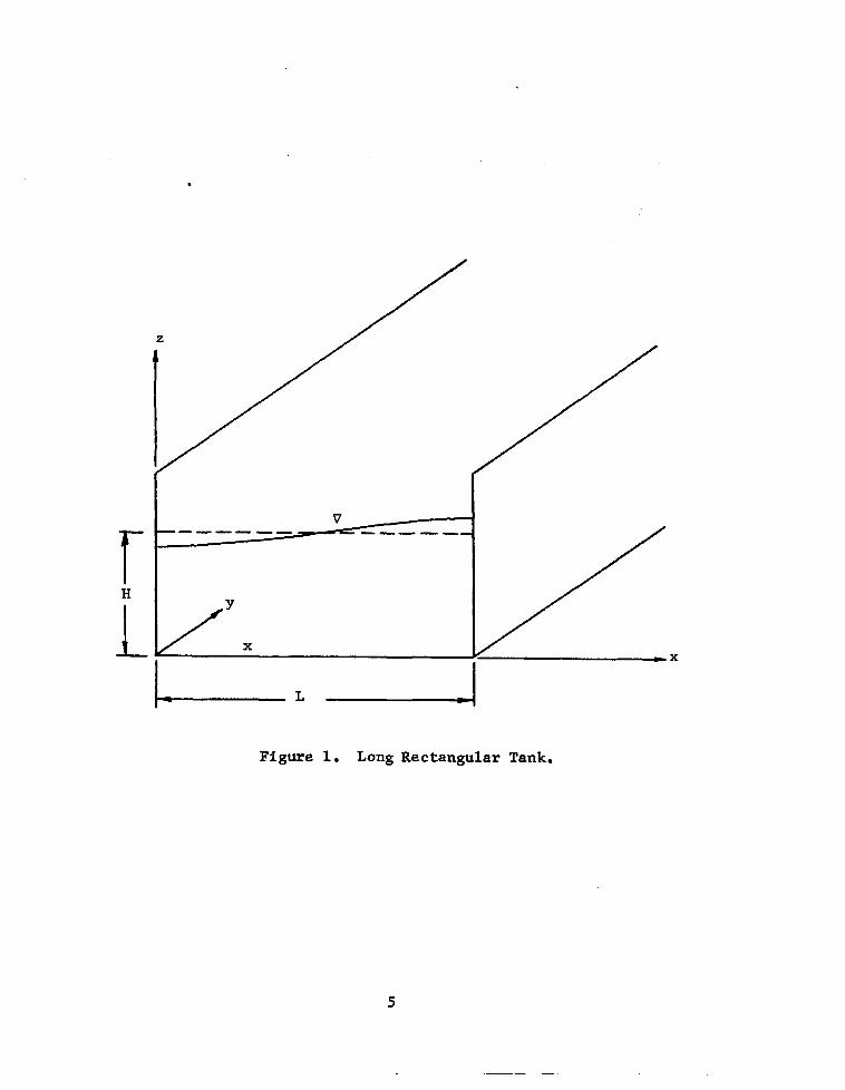
The geometry of the system under study is shown in Figure 1. For a long,
rectangular tank, the fluid particles are assumed to move in vertical planes.
The motion of the liquid is therefore independent of y. The boundary condi-
tions at the free surface of the liquid, and at the interfaces of the tank are
2 =o, I x=0
$$ =o, 1 x=L
[ 2 u+g
at2 $g =o,
2=H
I = 0 (Rigid bottom) , z-o
I z=o = g (Elastic bottom) ,
(2)
(3)
(4?
(5a)
(5b)
where w is the transverse displacement of the plate, g is the gravitational
acceleration, and t is the time.
When harmonic motion is assumed for the system, the general solution
of Equation (l), in conjunction with the boundary conditions (2), (3)j and
(4) is found to be
4
.
f H
1 .
IL c
Figure 1. Long Rectangular Tank.
5

co
q3(x,z,t) = eiWt cd A cash y-f- y, sinh y 1 cash F , (6) I11=0
where
PO mrr ml-rI3 - w2 cash 9 Ym = w2 ;iiig g(F) cash y '
(7)
and where u) is the natural circular frequency of the system.
For a tank with a rigid bottom the satisfaction of Equation (5a) results
in the frequencies am of the liquid oscillation
(8)
For a tank with an elastic bottom the elastokinetic behavior of the
bottom is governed by the plate equation:
where w is the transverse displacement with respect to static equilibrium
position, D is the plate rigidity, p is the plate density, h is the plate
thickness, and the pressure p, on the plate is
Dv4w + ph 2
aw at2
= p I
, (9) z=o
P I
292 z=o = Pf at z=O I (10)
Again, for a long tank, Equation (10) is independent of y. Substitution of
Equation (6) into Equation (9), in conjunction with E'quation (10) yields:
D 9 + ph 2 = pfiwiwt Jo Am cos 7 . (11)
6
II -
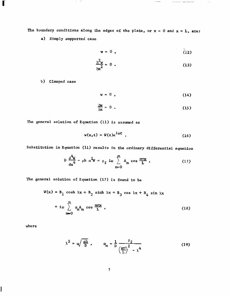
The boundary conditions along the edges of the plate, or x = 0 and x = L, are:
a) Simply supported case
w= 0, i‘12)
$0. (13)
b) Clamped case
w=o,
a=o. ax
(14)
(15)
The general solution of Equation (11) is assumed as
w(x,t) = W(x)eicot . (16)
Substitution in Equation (11) results in the ordinary differential equation
Dd!i dx4
- ph u?W = pf iw c Am cos y . III=0
The general solution of Equation (17) is found to be
W(x) = B1 cash Ax + B2 sinh hx + B3 cos Xx + B4 sin AX
01
+ iw c *mAm
ml-TX cos - L' Ill=0
where
A2 = q/ D , -z am = ;
( > m7T
if
L - A4
7
(17)
(18)
(19)

The respective application of the boundary conditions (12), (13) or (15) and
(16) then has the result that the arbitrary constants B1, B2, B3 and B4 may
be expressed in terms of the Am as
OD
Bj = iw 1 Bjm cyrn Am Cl = 1,2,3, and 4) , IIFO
in which the B Sm
have the forms:
a) Simply supported case
where
Slm= -2~ l r1 l ("'>'I , -7 L
p 2m = 4 [ ‘coth AL - cos mT sinh ALI' - $ (~1~1 ’
133m = - 3[1 + $(F)2] ,
1 f3, = 2 [ cot AL - ~~1+$(~)2]
b) Clamped case
6. =Bjl+B Jm j2 cos ml-r ,
B1l = 1 - cash AL cos AL - sinh AL sin AL
Z(cosh AL cos XL - 1) ,
B12 = cash AL - cos hL
2(cosh AL cos ;IL - 1) '
B31 = 1 - cash AL cos AL + sinh hL sin IL
2(cosh AL cos AL - 1) ,
(20)
(22)
(23a)
(23b)
(23~)

B32 = - B12 ' (2%)
B B21 = - B41 =
31 sin AL - Bll sinh AL cash AL - cos XL , (2-k)
B22 = - Bb2 = B32 sin XL - B12 sinh IL cosh1L - cos AL , (23f 1
The functions cash Ax, sinh Ax, cos Ix and sin Ix can be expanded as Fourier
cosine series in 7. As a result, the general solution for the transverse
deformation of the plate may be written as:
w(x,t) = iwe iwt{ 7 am [$ (B,,,,a, + 8,,b, + B3,,,co + 8,,.,,d,) llF0
(24) CD CJ + c (8 lman + 8,,b, + B3"cn + 84,,,dn> ~0s y 1 c + (Y cos EEL n 1 L'
n=l n=O
where
a 0
= 2 sinh hL ,
a = 2A sinh AL cosn rr n L[h2 + (?)'I '
b. = $ (cash AL - 1) ,
bn = *-p-$g=~ [c-h hL coy nn - 11 ,
C 0
= 2 sin IL , AL
(25a)
(25b)
(25e)
(25f)
do = 6 (1 - COS hL)
dn = -p-@j Cl - ws U cosn 73
.cr%)
(25h 1
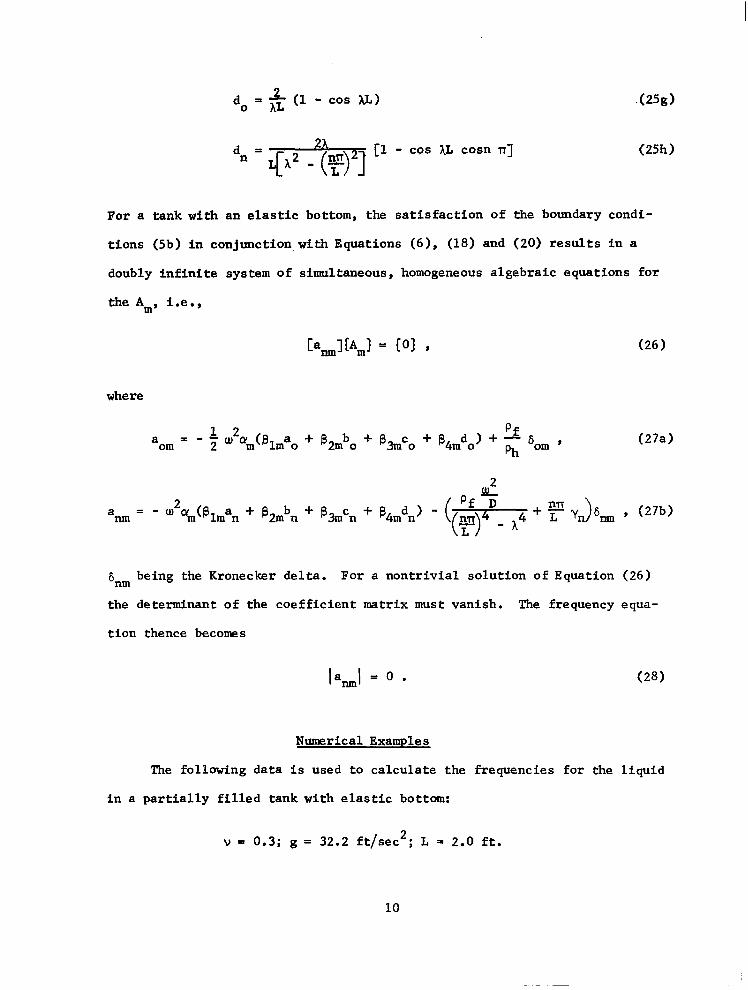
For a tank with an elastic bottom, the satisfaction of the boundary condi-
tions (5b) in conjunction,with Equations (6), (18) and (20) results in a
doubly infinite system of simultaneous, homogeneous algebraic equations for
the Am, i.e.,
[amlfArn3 = CO1 s
where
of a = om - $ ~2~m(slm~o + B2mbo + 83mco + B4,do) + - 6, ,
oh
(26)
(27a)
2
- w2amtelman + 8 2mbn + @3mcn + g4mdn) - ( of % a l-m=
( > s4+4 + y r, > 6, 9, (27b) L
6 nm being the Kronecker delta. For a nontrivial solution of Equation (26)
the determinant of the coefficient matrix must vanish. The frequency equa-
tion thence becomes
Ia,1 = 0 l (28)
Numerical Examples
The following data is used to calculate the frequencies for the liquid
in a partially filled tank with elastic bottom:
v = 0.3; g = 32.2 ft/sec2; L = 2.0 ft.
10
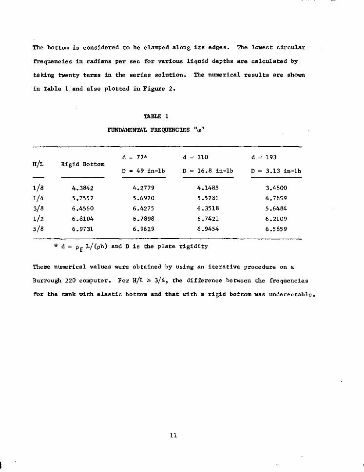
The bottom is considered to be clamped along its edges. The lowest circular
frequencies in radians per set for various liquid depths are calculated by
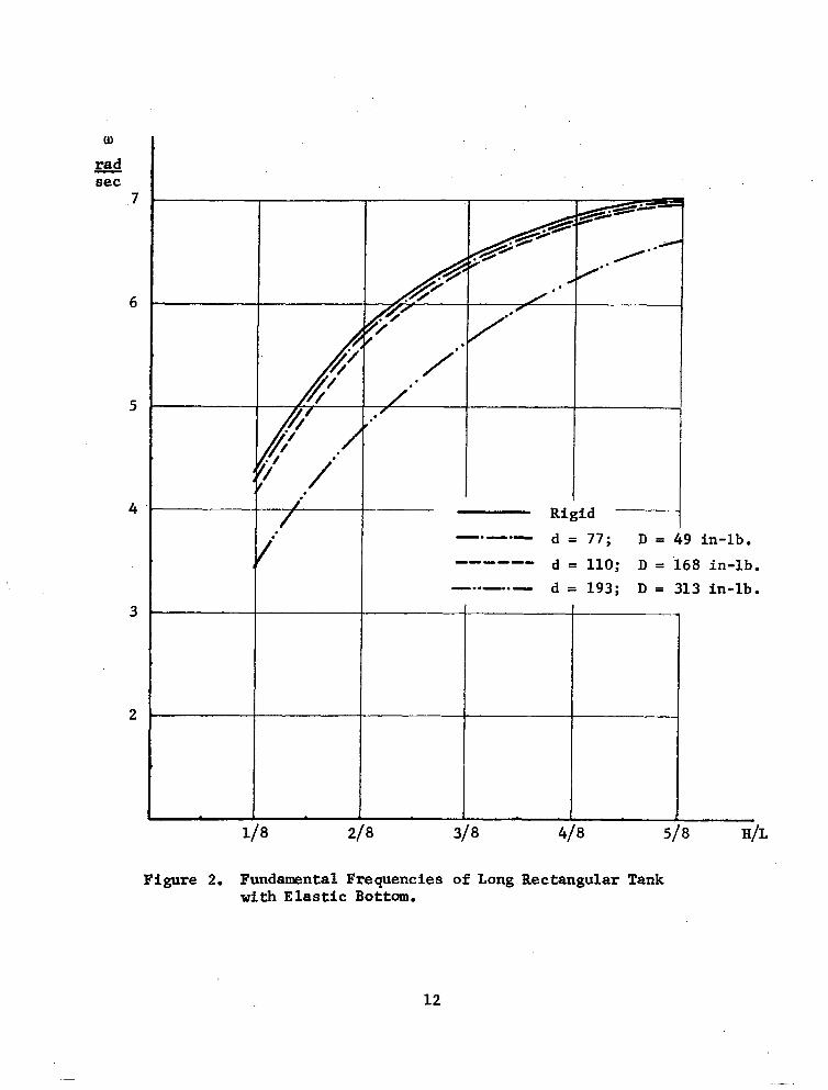
taking twenty terms in the series solution. The numerical results are shown
in Table 1 and also plotted in Figure 2.
TABLE 1
FUNDAMENTAL FRRQUENCIRS "u?
d = 77* H/L Rigid Bottom
D = 49 in-lb
118 4.3842 4.2779 l/4 5.7557 5.6970 318 6.4560 6.4275 112 6.8104 6.7898 5/8 6.9731 6.9629
d = 110 d = 193
D = 16.8 in-lb D= 3.13 in-lb
4.1485 3.4800 5.5781 4.7859 6.3518 5.6484 6.7421 6.2109 6.9454 6.5859
* d = pf L/(ph) and D is the plate rigidity
These numerical values were obtained by using an iterative procedure on a
Burrough 220 computer. For H/L zz 3/4, the difference between the frequencies
for the tank with elastic bottom and that with a rigid bottom was undetectable.
11
:
.
Rigid ~- -.-.N d ~77; D=d 9 in-lb. -a---- d = 110; D = 168 in-lb. -..-..- d = 193; D = 313 in-lb.
8 H/L
Figure 2. Fundamental Frequencies of Long Rectangular Tank with Elastic Bottom.
12
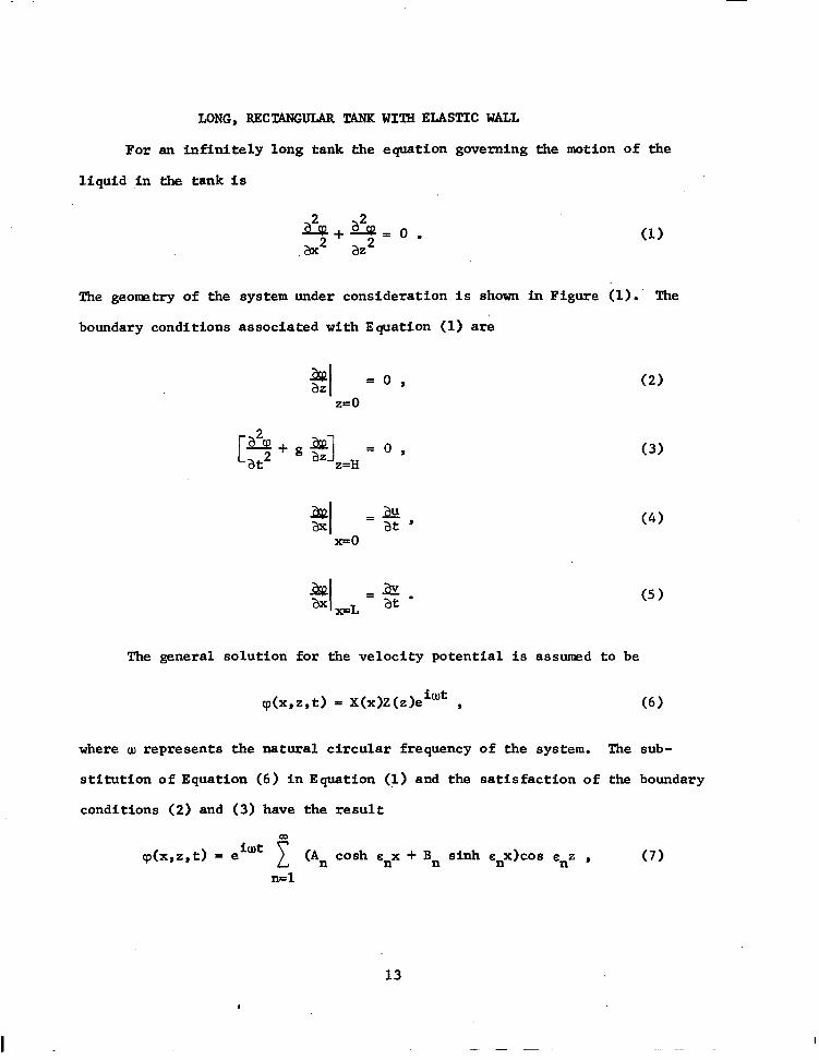
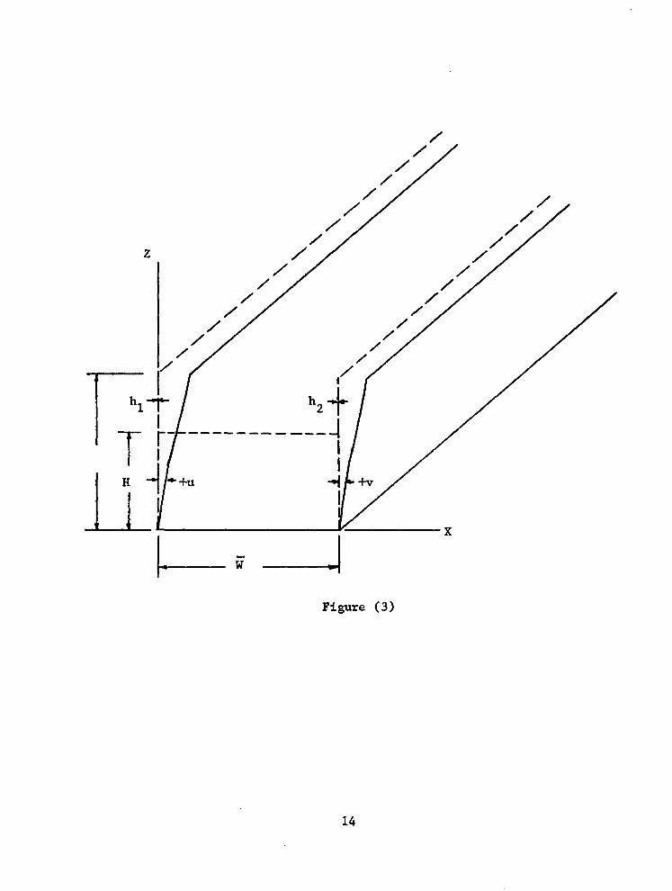
LONG,RECUNGULAR TANKWIIHE~SIIC WALL
For an infinitely long tank the equation governing the motion of the
liquid Jn the tank is
(1)
The geonretry of the system under consideration is shown in Figure (1): The
boundary conditions associated with Equation (1) are
$f =o, I z=O
[ A+ga co at2 aZ 1 , 2=H
2 I =$, xX0
2 I =a FL at .
(2)
(3)
(4)
(5)
The general solution for the velocity potential is assumed to be
cp(x,z,t) = X(x)Z(z)e iwt ,
where w represents the natural circular frequency
stitution of Equation (6) in Equation (1) and the
conditions (2) and (3) have the result
(6)
of the system. The sub-
satisfaction of. the boundary
co
cp(x,z,t) = e iwt 1 (An cash cnx + Bn sinh e,x)cos snz , (7)
n=l
I
13
/
Figure (3)
14
where the G, are the roots of the equation
u?H sH tan eH = - -i- l
The equation of motion of the wall along x=0 is
++- Plhl && a2
=pg D1 at2 1 I x=0
(8)
(9)
The assumption of harmonic motion of the form
p(Z,t) = U(z)eiwt , (10)
and substitution of this expression in Equations (1) and (9), has the result
An cos snz .
The general solution of this equation is
U = Bl coshhlz + B2 sinh hlz + B3 cos )clz + B4 sin Xlz
+- pf (id f :I 4 D1
cos enz , n=l an 1
which must satisfy the possible boundary conditions:
a) Simply supported
p(O) = p(L) = 0 ,
c1"(0) = VW(L) = 0 .
b) Both edges fixed
p(O) = p(L) = 0 ,
CL'(O) = u'(L) = 0 .
(11)
(12)
(13)
(14)
15
.-_-.- .-.--- . -_.. -. -
Both edges of the walls will be considered fixed-here. The integration
constants Bj (j = 1 to 4) can be expressed in terms of An by applying the
boundary conditions shown in Equation (14). They are found to be
0) .BJ = c Klcl
u=l
pf(iw) A
D Cc 1 P 4-a14) ’ (15)
where
1
KIIJ, = - cash ALL cos AlL - sinh XlL sin )clL + cos s L (cash AlL - cos hlL)
2(cosh XlL cos AlL - 1)
ZLL sin sPL (sinh IlL - sin hlL) + 3
2(cosh $L cos XlL - 1) 9 (16)
K2u =
cash hlL sin AlL + sinh $L cos XlL - cos c L (sinh hlL + sin )clL) Z(cosh $L cos 7clL - 1)
E '2 sin suL (cash hlL - cos AlL) ll
2(cosh hlL cos AlL - 1) 9 (17)
(cash AlL - cos XlL) 2(cosh AlL cos XlL - 1)
e -L sin suL (sinh $L - sin AlL) Al
Z(cosh XlL cos hlL - 1) 9
K4u= -K2u l
The equation of motion of the wall along x = J? is
4 Y+
-,,pf& P2h2 az D2 D2 at Sk?
(18)
(19)
(20)
16
-
The solution of Equation (20) is assumed in the following form:
iwt v=V(z)e .
Substitution of Equations (7) and (21) into Equation (20) gives
d4V -- dZ4 I2 (An cash snk + Bn sinh snR) cos snz ,
where
A2 4 _ p2h2 w2
D2
The general solution of the Equation (22) is
V = Al* cash h2z + B2* sinh h2z + B3* cos A2z + B4* sin h2s
Pf(iW) - +- 1 1
D2 n=l ' n4-a24 (An cash enR + Bn sinh s,J) cos sns .
(21)
(22)
(23)
'l'he application of the boundary conditions (14) results in the expressions
cash E$ + BP sinh s&J) (24)
for the integration constants B *. -i
It is assumed that the liquid remains in contact with the wall through-
out the motion. The conditions shown in Equations (4) and (5) must be satis-
fied. The relationships for the
become
determination of the coefficients An and B n
An + snB Ill CO8 en2 + $ F & [Klu cash hlz u=l su -l1
+ K2u sinh Xlz + K3u cos hlz + Kc sin hlzl = 0 (25 1
17
I IN..
and
OJ IQ:
Pf w2
sn sinh e,l, + n=l D2(cn4-124)
cash en1 1 An +
E, cash ena + Pf w2
n2(cn4-X24)
sinh sna IS B l cos anZ +
(26)
PfW2 a, A cash E R + B sinh e 1 +-
D2 c LA
v=l CC ,4-h24)
CKq.L cash x2z + K 21.1
sinh A2z +
+ K3p cos A2z + K
4lJ sin A2z] = 0
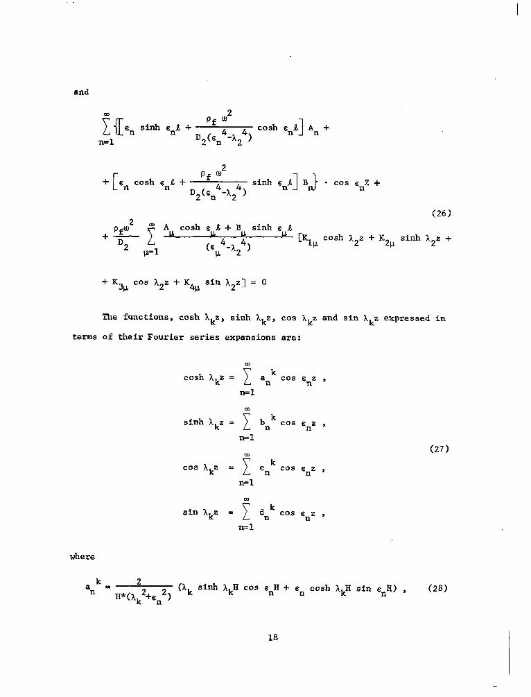
terms
The functions, cash hkz, sinh hkz, cos hkz and sin hkz expressed in
of their Fourier series expansions are:
cash Akz = c ak n cos enz , n=l
m sinh )ckz = c bk n cos snz ,
n=l (27)
co
cos AkZ = 1
Ck n cos en2 ,
n=l
co sin ‘hkz = c dk n co.5 enz ,
n=l
where
ak 2 P n H*(lk2+en2) (ak sinh lkH cos snH + en cash XkH sin enR> , (28)
18
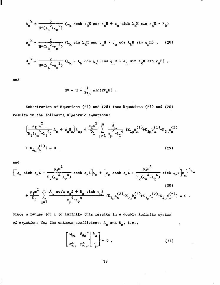
bk= 2 n H*(ak2+Cn2) ('k cash hkH cos s,H + s n sinh hkH sin snH - hk)
Ck 2 = n H*(Ak2-sn2) (ak
sin AkH cos enH - cn cos AkH sin snH) , (28)
dk 2 = n H*(hk2-cn2) (hk - ak cos ~~~ cos snH - en sin hkH sin c,H) ,
and
1 H*-H+2611
Substitution of Equations (27)
sin(20nH) .
and (28) into Equations (25) and (26)
results in the following algebraic equations:
Pf w2 Pf’u2 a ALL
,(sn4-a14) An+ cnB 6 +-
w D1 1 p=l =p 4-a14
+ Kbdil)) - 0
and 7
(Kl ALl)+K2ubil)+K3 CL P
c;')
(29)
3
(II PfW” 'n sinh ena +
D2(sn4-h24) cash sna]~n + [en cash sna + D2(I':, 4) sinh snJ]BJb
2
(30) PfW2 OD A cash e 1 + B sinh e R
+- D2 1 lL
CCL 4-a24 u (Klua~2)+K2pb~2)+K3Fc~2)+K4pd~2)) = 0 .
P=l
Since n ranges for 1 to infinity this results in a doubly infinite system
of equations for the unknown coefficients An and Bn, i.e.,
(31)
19
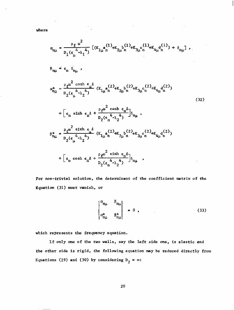
where
Pf w2
aw = D (c 4-h14) [(Kl;~1)+K2Pb~1)+K3pc~1)+K4pd~1)) + $u], ,
1 CL
pfw2 cash e a &=
"12 D2(s 4-h24) u (Kl,a~2)+K2Pb~2)+K3Pc~2)+K41Ld~2))
P (32)
+ en sinh eni + [ pfw2 cash s,A
D2(~n4-h24) 1 6nP '
e 1 p* =
pfw2 sinh
w D (e u (Klua~2)tK2ub~2)+K3Pc~2)+K4Pd~2))
2 c1 4-A24)
en cash e,A + PP2 sinh enA 1 6 9 D2(sn4-X24) ‘+
For non-trivial solution, the determinant of the coefficient matrix of the
Equation (31) must vanish, or
(33)
which represents the frequency equation.
If only one of the two walls, say the left side one, is elastic. and
the other side is rigid, the following equation may be reduced directly from
Equations (29) and (30) by considering D2 = a:
20
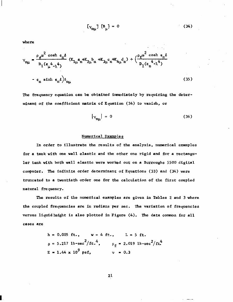
Cv,,l @,I = 0 (34)
where
p w2 cash snA 2 cash snA Y = w Dl(s 4 4
(Klpan+K2FPn +K3pcn+K4,dn> + ( pp p -a 1 Dl(en4ih4)
- en sinh s,R 6 "P
(35)
The frequency equation can be obtained inxnediately by requiring the deter-
minant of the coefficient matrix of Equation (34) to vanish, or
Iv,,1 = 0 (36)
Numerical Examples
In order to illustrate the results of the analysis, numerical examples
for a tank with one wall elastic and the other one rigid and for a rectangu-
lar tank with both wall elastic were worked out on a Burroughs 5500 digital
computer. The infinite order determinant of Equations (33) and (34) were
truncated to a twentieth order one for the calculation of the first coupled
natural frequency.
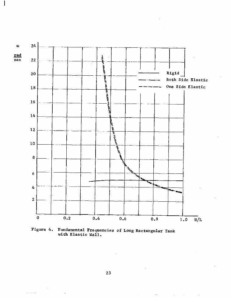
The results of the numerical examples are given in Tables 2 and 3 where
the coupled frequencies are in radians per sec. The variation of frequencies
versus liquidheight is also plotted in Figure (4). The data conrmon for all
cases are
h = 0.005 ft., w = 4 ft., L= 5 ft.
P E 5.217 lb-sec2/ft.4, of = 2.019 lb-sec2/ft!
E - 1.44 x 10' psf, V = 0.3
21 -

TABLE 2
FlMDAMENTAL CIRCULAR FREQUENCIES FOR A PARTIALLY LIQUID FILIED RECTANGlJI& TANK HAVING ONE WALL ELASTIC AND THE OTHER ONE RIGID
5
4.6 4.2 3.8 3.4 3.0 2.6 2.2 1.8
H/L rad/sec w
1 3.31
0.92 3.70 0.84 4.18 0.76 4.81 0.68 5.73 0.60 7.32 0.52 11.93 0.44 22.49 0.36 22.49
0 rad/sec*
5.03
5.03 5.02 5.02 5.00 4.97 4.95 4.87 4.74
* Rigid tank slosh frequencies
TABLE 3
FUNDAMENTAL CIRCULAR FREQUENCIES FOR A PARTIALLY LIQUID FILLED RECTANGULAR TANK WITH BOTH WALLS ELASTIC
H ft H/L 5 1 4.6 0.92 4.2 0.84
3.8 0.78 3.4 0.68 3.0 0.60
2.6 0.52 1.8 0.36
a rad/sec
3.21 3.61 4.09 4.71 5.62 7.21
11.79
22.01
Q rad secf
5.03 5.03 5.02
5.02 5.00 4.97 4.95 4.74
* Rigid tank slosh frequencies
22
0) 24
& set 22
20
18
16
8
6
--
-.-.-.-
I I I $ I I ' ' dieid I ----- One Side
T- I I I \\ I
I I I
I I
t--k I I\,1 I I I I I I I i k-t--~~
I\\1 I I I I
0.2 0.4 0.6 0.8 1.0 H/L
: Elastic Elastic
Figure 4. Fundamental Frequencies of Long Rectangular Tank with Elastic Wall.
23
CYLINDRICAL TANK WITH ELNL'IC WALL
The governing differential equation for the axisynrnetrical motion of
liquid in cylindrical coordinates is
The boundary conditions, which must be satisfied at the rigid bottom and at
the free surface of the liquid are
e =o, I Z=O
(2)
(3)
(4)
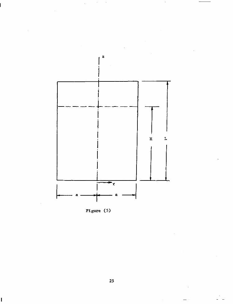
The geometry of the system under consideration is shown in Figure (5).
A separable solution for Equation (1) is assumed and the motion is
considered to be harmonic. The velocity potential cp thus takes the form
&,z,t> = R(r) z (z)e irut (5)
where UI is the natural frequency of the system. The general solution of the
Equation (lj with Equations (2), (3), and (4) all satisfied is found to be
m . u(r,z,t) = eiwt c An cos cnz Io(snr) , (6)
n=l
where s n are the roots of the Equation
2 sH tan sH = - k". (7)
24 -
-
I I . ! c ----- ---m . ! I
I. I L L
I- I a -+I'.
1
H
t
L
Figure (5)
25

The pressure at the tank wall is
cn
32 of at ra I_
= pf(icu)elwt c An cos c,z Io(sna) . n=O
(8)
Ihe following differential equation governing the motion of the cylinder is
used:
r=a (9)
Equation (9) is derived based on the assumption that the longitudinal inertia
of the shell has negligible effect on the motion of the shell. The trans-
verse displacement, w, is defined to be positive if it moves along inward
normal direction. Ihe motion of the cylinder is assumed to be harmonic and
takes the form
w(r,t) = W(r)e icot . (10)
Substitution of Equation (10) into Equation (9) results in the following
ordinary differential equation:
4 dW + 4h4 w = 2 dz4
An cos snz Io(sna) , n=O
where
4A4 = c+ - ohw2)*. a
(11)
(12)
The boundary conditions for the cylindrical shell are
a) Simply supported
26
w =o, (13)
w =o. zz (14)
b) Clamped edge
w =o, (15)
w =o. 2 (16)
The general solution of the differential equation (11) is found to be
w = ehz(Bl cos AZ + B2 sin hz) + emhz(B3 cos hz i- B4 sin AZ)
(17) O3 Io(sna)An
- 2 (icu) 1 4 + 4h4 'OS snz
n=l sn
where B 1' B2, JJ3r and B4 are integration constants which may be expressed
in terms of Fourier coefficients An when the boundary conditions shown in
Equations (13), (14), and/or Equations (15) and (16) are applied.
For a cylindrical tank clamped along both ends, boundary conditions
shown in Equations (15) and (16) must be satisfied. The integration con-
stants B 1' B2, B3, and B 4 are found to be
B.i = co pf(idIo(~ dA 1 D(s 4 + 4h4) kw j = l lzo 4 l
u=l P
where
1 Klp = - q -i qI emA cos o$(sin hL - cos AL) - $ sin 8 uL sin hL 1
cos s+(sin AL + cos AL) + + sin suL sin hL 1
(18)
+ e-2= - 2 - sin(2AL) + COS (2AL)]
27
K2p = -‘rCK
c2 L 3 lp - 2 CO8 e @
sin AL + F sin 6 G
(sin AL + cos AL) 1
K% =+(l+K ) 1P
K4P =+(2K +K
1P 2p + 1)
and
Cl = 4 - 2 cos 2hL - e 2XL _ .-2XL
C2 =e AL [2 + sin(2hL) - cos(2XL)] - emAL
C3 =e -AL - ehL [sin(2XL) + cos(2hL)J
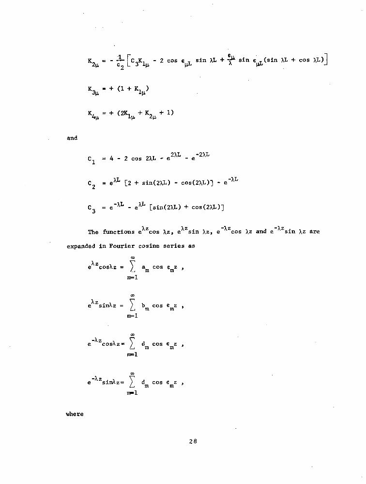
The functions e AZ cos AZ, e AZ sin hz, e -AZ cos Xz and e -hz sin AZ are
expanded in Fourier cosine series as Co
ehz COSAZ = 7 a -2 m cos emz , m=l
CD
AZ e sinhz = 1 bm cos crnz ,
ml
CD -AZ e coshz = c dm cos smz ,
IlFl
m
-AZ e sinXz= 1 dm cos emz , rrpl
where
28
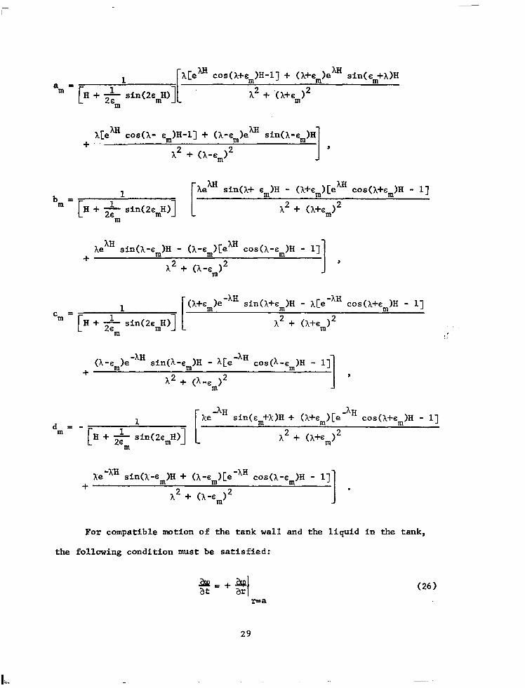
1 A[eXH cos(h+em)H-1) + (A+e,)e AH sin(sm+A)H a = m
C H + &- sin(2cmH)] A2 f .(A+em12 m
A[ea
+ -- cos(h- s,)H-l] + (A-sm)ehll sin(h-sm)H
A2 + (bernI 1 , Aem AH
b 1 sin(A+ s,)H - (A+c,)[e cos(X+s,)H - l] = m l-I+* sin(2smH)] A2 + (A+em)2
m
he AH sin(A-sm)H - (A-c,)[e AH co&-cm)H - 1] +
A2 + (A-Q2 1 , (A+em)emAH
-AH 1 sin(Xi-cm)H - x[e cos(h+em)H - l]
C = m C II++ sin(2smH)] A2 + tA+em)2
m
0 -em)e -AH sin@-sm)H - h[e -AH +
cos@-em)H - l] 1 A2 + I 9
dm = - 1 H++ sin(2emH)]
m
Xe -lH sin(sm+A:)H + (h+sm)[e -hH cos(l+sm)H - l]
A2 + (A+Em12
+ XewxH sin()i-sm)H + (A-~,)[~-~H cos(h-sm)H - l]
A2 + (A-Em)2 1 . For compatible motion of the tank wall and the liquid in the tank,
the following condition must be satisfied:
, !I
++a ar I
r=a (26)
29
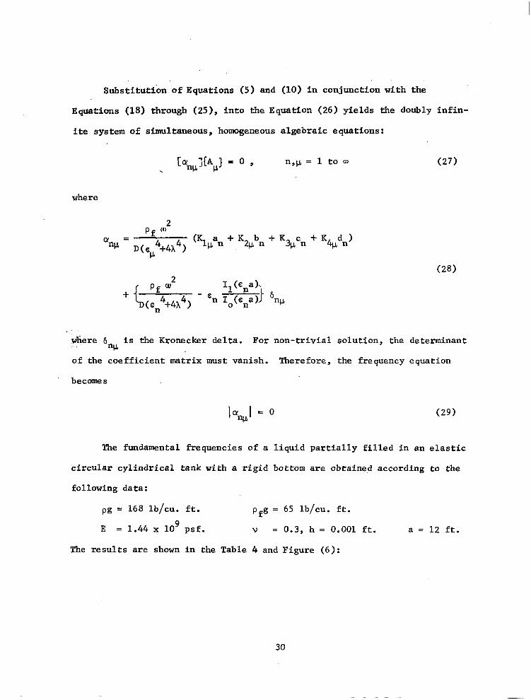
Substitution of Equations (5) and (10) in conjunction with the
Equations (18) through (25), into the Equation (26) yields the doubly infin-
ite system of simultaneous, homogeneous algebraic equations:
n¶CL =1toa (27)
where
Q = w D(eP4+4A4) (Kluan + K2Vbn + K
5 % cn + K dn)
(28)
+ c
Pf w2 I1 (ena)
(en4+4h4) - sn Io(cna) 1 6 nu
where 6 is the Kronecker delta. "CL
For non-trivial solution, the determinant
of the coefficient matrix must vanish. Therefore, the frequency equation
becomes
lffnpI = 0 (29)
The fundamental frequencies of a liquid partially filled in an elastic
circular cylindrical tank with a rigid bottom are obtained according to the
following data:
pg = 168 lb/cu. ft. pfg = 65 lb/cu. ft.
E = 1.44 x 10' psf. V = 0.3, h = 0.001 ft. a = 12 ft.
The results are shown in the Table 4 and Figure (6):
30
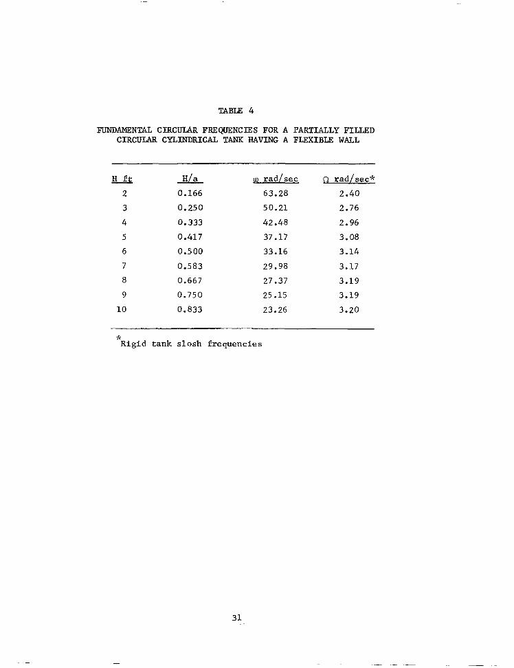
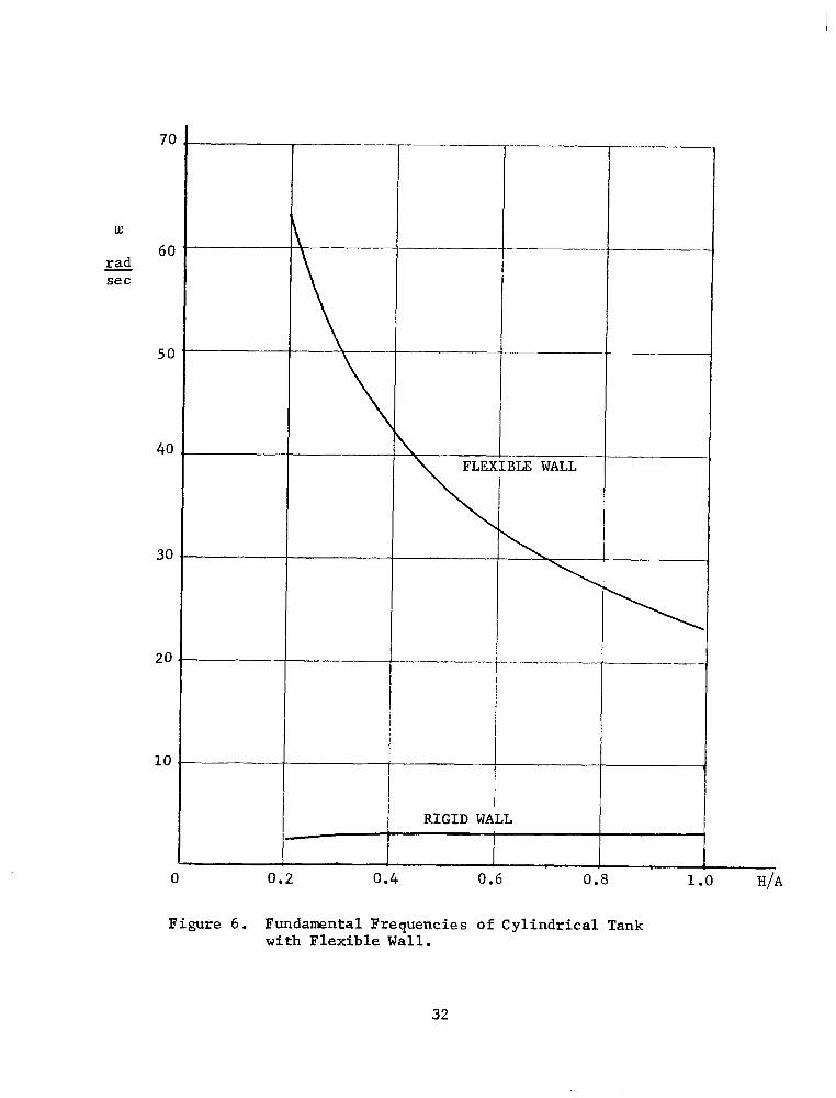
TABLE 4
FUNDAMENTAL CIRCULAR FREQUENCIES FOR A PARTIALLY FILLED CIRCULAR CYLINDRICAL TANK HAVING A FLEXIBLE WALL
H H/a w rad/sec D rad/sec*
2 0.166 63.28 2.40
3 0.250 50.21 2.76
4 0.333 42.48 2.96
5 0.417 37.17 3.08
6 0.500 33.16 3.14
7 0.583 29.98 3.17
8 0.667 27.37 3.19
9 0.750 25.15 3.19
10 0.833 23.26 3.20
* Rigid tank slosh frequencies
31
---
70
w 60
J& set
50
40
30
20
10
z -
-
ILE WALL
/
RIGID WALL I
0 0.2 0.4 0.6 0.8 1.0 H/A
Figure 6. Fundamental Frequencies of Cylindrical Tank with Flexible Wall.
32
DISCUSSIONS
The coupled oscillations of a liquid partially filled in a container
having an elastic bottom or elastic walls have been studied. Two different
tank configurations, namely a rectangular and a circular container both
with flat bottoms were considered. Since the effect of the flat elastic
bottom of a circular cylindrical tank to the frequencies of the system has
been studied by several authors [SJ, [4], etc. Therefore, no further inves-
tigation is attempted in this report. The methods used for both configura-
tions are similar and straight forward. The effects of the flexibility of
the container may be summarized according to the results of the numerical
examples presented previously.
1. The flexibility of the bottom of a rectangular tank reduces the
natural frequencies of the system. The frequency increases as the depth of
the liquid increases and gradually approaches to the value corresponding to
the case of a rigid container. According to the numerical examples worked,
the effect of the flexibility of the bottom becomes negligibly small when
the depth of the liquid H is increased to approximately three-fourth of the
width of the tank.
2. For the cases where the flexibility of the container walls of a rec-
tangular tank are taken into account, the lowest frequency of the system
occurs when the tank is completely filled. The frequencies increase as the
depths of the liquid decrease. The frequencies exceed the value correspond-
ing to rigid tank case when the depth of liquid, H, is gradually reduced to
approximately three-fifth of the container height.
3. The corresponding natural frequencies for a rectangular tank having
one flexible wall are slightly higher, but not appreciable, than the case
having both walls flexible.
33
I -
4. The frequency increases as the depth of liquid decreases in a
circular cylindrical container having a flexible wall.
1.
2.
3.
4.
5.
6.
7.
References
Miles, J. W., "On Sloshing of Liquid in a Flexible Tank," J. Appl. M-h., 25 June 1958. -,
Bleich, H. H., "Longitudinal Forced Vibrations of Cylindrical Fuel Tanks," Jet Prop., 2, February 1956.
Bhuta, Pravin G. and Koval, Leslie R., "Coupled Oscillations of a Liquid with a Free Surface in a Tank," ZAMP, Vol. 15, 1964.
Siehnann, J. and Chang Shih-Chih, "On Liquid Sloshing in a Cylindrical Tank with a Flexible Bottom," Southeastern Symposium on Missiles and Aerospace Vehicles Sciences, American Astronautical Society, December, 1966.
Hwang, Chintsum, "Longitudinal Sloshing of a Liquid in a Flexible Hemispherical Tank," J. Appl. Mech., Trans. ASME, 1965.
Coale, C. W. and Nagano, M., "Axisymmetric Modes of An Elastic Cylindrical-Hemispherical Tank Partially Filled with a Liquid," AIAA Symposium on Structural Dynamics and Aeroelasticity, August 30 - September 1, 1965.
Gossard, Myron L., "Axisymmetric Dynamic Response of Liquid-Filled, Hemispherical, Thin Walled, Elastic Tanks," AIAA Symposium on Struc- tural Dynamics and Aeroelasticity, August 30 - September 1, 1965.
34 NASA-Langley, 1967 - 32 ~~-882
“The aeronautical and space activities of the United States shall be conducted so as to contribute . . . to the expansion of human knowl- edge of phenomena in the atmorpbere and space. The Admhistration shall provide for the widest practicable and appropriate dissemination of information concerning its activities and the results tbereof.”
-NATIONAL AERONAUTICS AND SPACE ACT OF 1958
NASA SCIENTIFIC AND TECHNICAL PUBLICATIONS
TECHNICAL REPORTS: Scienti6c and technical information considered important, complete, and a lasting contribution to existing knowledge.
TECHNICAL NOTES: Information less broad in scope hut nevertheless of importance as a contribution to existing knowledge.
TECHNICAL MEMORANDUMS: Information receiving limited distribu- tion because of preliminary data, security classification, or other reasons.
CONTRACTOR REPORTS: Scientific and technical information generated under a NASA contract or grant and considered an important contribution to existing knowledge.
TECHNICAL TRANSLATIONS: Information published in a foreign language considered to merit NASA distribution in English.
SPECIAL PUBLICATIONS: Information derived from or of value to NASA activities. Publications include conference proceedings, monographs, data compilations, handbooks, sourcebooks, and special bibliographies.
TECHNOLOGY UTILIZATION PUBLICATIONS: Information on tech- nology used by NASA that may be of particular interest in commercial and other non-aerospace applications. Publications include Tech Briefs, Technology Utilization Reports and Notes, and Technology Surveys.
Details on the availabilify of these publications may be obtained from:
SCIENTIFIC AND TECHNICAL INFORMATION DIVISION
NATIONAL AERONAUTICS AND SPACE ADMINISTRATION
Washingon, D.C. PO546