lm2706 miniature, variable, step-down dc-dc converter with bypass for rf … sheets/national... ·...
TRANSCRIPT

LM2706Miniature, Variable, Step-Down DC-DC Converter withBypass for RF Power AmplifiersGeneral DescriptionThe LM2706 DC-DC converter is optimized for powering RFpower amplifiers (PAs) from a single Lithium-Ion cell. It mayalso be used in many other applications. It steps down aninput voltage from 2.7V to 5.5V to a variable output from1.5V to 3.25V up to 300 mA. Output voltage is set using aVCON analog input for controlling power levels and efficiencyof the RF PA. An internal bypass switch allows direct con-nection to the battery for maximum power to the RF PA.
The device offers 4 modes for mobile phones and similar RFPA applications. Fixed-frequency PWM mode minimizes RFinterference. Forced Bypass mode turns on an internal by-pass switch to power the PA directly from the battery. Auto-matic bypass mode minimizes dropout by turning on thebypass switch when the battery decays to near the outputvoltage. Shutdown mode turns the device off and reducesbattery consumption to 0.1 µA (typ.).
The device also offers internal synchronous rectification forhigh efficiency (95% typ at 3.25 VOUT, 200 mA, 3.9 VIN).Current limit and thermal overload protection protects thedevice and system during fault conditions.
The LM2706 is available in a 10-pin lead free micro SMDpackage. This packaging uses National’s chip-scale microSMD technology and offers the smallest possible size. A highswitching frequency (600 kHz) allows use of tiny surface-mount components. Only three small external surface-mountcomponents, an inductor and two ceramic capacitors, arerequired.
Key Specificationsn Operates from a single LiION cell (2.7V to 5.5V)n Variable output voltage (1.5V to 3.25V)
n ±2% DC output voltage precisionn Internal 105 mΩ (typ) bypass switchn 300 mA maximum load capabilityn 1.4 mA typ quiescent currentn 0.1 µA typ shutdown currentn 600 kHz PWM switching frequencyn High efficiency (95% typ at 3.9 VIN, 3.25 VOUT at
200 mA) from internal synchronous rectification
Featuresn Forced and Automatic Bypass modesn Miniature 10-pin lead free micro SMD packagen Only three tiny surface-mount external components
requiredn Uses small ceramic capacitorsn Low output voltage ripple (<10 mV typ)n Internal soft startn Current overload protectionn No external compensation
Applicationsn Mobile Phonesn Hand-Held Radiosn RF PC Cardsn Battery Powered RF Devices
Typical Application Circuit
20040901
PRELIMINARYFebruary 2004
LM2706
Miniature,Variable,S
tep-Dow
nD
C-D
CC
onverterw
ithB
ypassfor
RF
Pow
erA
mplifiers
© 2004 National Semiconductor Corporation DS200409 www.national.com

Connection Diagrams10-Bump micro SMD Package 10-Bump micro SMD Package
20040902
Top View20040903
Bottom View
Ordering Information
Order Number Package TypeNSC Package
Marking (*)Supplied As
LM2706TL 10-Bump WaferLevel Chip Scale
(micro SMD)XYTT IS64B
250 Tape and Reel
LM2706TLX 3000 Tape and Reel
(*) XY - denotes the date code marking (2 digit) in productionTT - refers to die run/lot traceability for productionI - pin one indicationS - Product line designatorNote the Package Marking may change over the course of production without notice
Pin DescriptionPin
NumberPin Name Function
A1 VDD Analog Supply Input. If board layout is not optimum, an optional 0.1 µF ceramic capacitor issuggested (Figure 1).
B1 VCON Voltage Control Analog Input. VCON controls VOUT in PWM mode. Set:VCON ≤ 0.55V for VOUT = 1.5V0.65V < VCON < 1.5V for VOUT = 1.75 VCON + 0.45VVCON ≥ 1.7V for VOUT = 3.25V
C1 ABD Automatic Bypass Disable. Use this digital input to control Automatic Bypass mode. Set:ABD = low to enable automatic bypass modeABD = high to disable automatic bypass mode
D1 BYP Bypass. Use this digital input to command operation in Forced Bypass mode. Set BYP = 0Vfor normal operation.
D2 EN Enable Input. Set this digital input high for normal operation. For shutdown, set low.
D3 PGND Power Ground
C3 SW Switching Node connection to the internal PFET switch and NFET synchronous rectifier.
B3 PVIN Power Supply Voltage Input to the internal PFET switch. Connect to the input filter capacitor(Figure 1).
A3 FB Feedback Analog Input. Connect to the output at the output filter capacitor (Figure 1).
A2 SGND Analog and Control Ground
LM27
06
www.national.com 2

Absolute Maximum Ratings (Note 1)
If Military/Aerospace specified devices are required,please contact the National Semiconductor Sales Office/Distributors for availability and specifications.
Supply Voltage, PVIN, VDD to SGND −0.2V to +6V
PGND to SGND −0.2V to +0.2V
EN, FB, BYP, ABD, VCON (SGND −0.2V) to(VDD +0.2V)
SW (PGND −0.2V) to(VDD +0.2V)
PVIN to VDD −0.2V to +0.2V
Storage Temperature Range −45˚C to +150˚C
Lead Temp. (Soldering, 10 sec) 260˚C
Junction Temperature (Note 2) +125˚C
Minimum ESD Rating ±2 kV
(Human Body Model, C = 100 pF, R = 1.5 kΩ)
Thermal Resistance (θJA) (Note 3) 137˚C/W
Electrical CharacteristicsSpecifications with standard typeface are for TA = TJ = 25˚C, and those in boldface type apply over the full Operating Tem-perature Range of TA = TJ = −25˚C to +85˚C. Unless otherwise specified, PVIN = VDD = EN = 3.6V, BYP = ABD = VCON = 0V.
Symbol Parameter Conditions Min Typ Max Units
VIN Input Voltage Range (Note 4) PVIN = VDD = VIN 2.7 3.6 5.5 V
VFB, MIN Regulated feedback voltage atminimum setting
VCON = 0VTA = 25˚C
1.47 1.50 1.53 V
VFB, MIN Regulated feedback voltage atminimum setting
VCON = 0V1.455 1.50 1.545 V
VFB, MAX Regulated feedback voltage atmaximum setting
VCON = 1.70VTA = 25˚C
3.185 3.25 3.315 V
VFB, MAX Regulated feedback voltage atmaximum setting
VCON = 1.70V3.15 3.25 3.35 V
OVP Over-Voltage protection Threshold VCON = 0V (Note 5) 260 350 445 mV
VBYPASS− Auto Bypass Detection Threshold VCON = 1.7V (Note 6) 160 275 390 mV
VBYPASS+ Auto Bypass Detection Threshold VCON = 1.7V (Note 6) 310 440 570 mV
ISHDN Shutdown Supply Current EN = ABD = BYP = SW = FB = 0VTA = 25˚C (Note 7)
0.1 1 µA
ISHDN Shutdown Supply Current EN = ABD = BYP = SW = FB = 0VTA = 55˚C (Note 7)
0.45 2 µA
ISHDN Shutdown Supply Current EN = ABD = BYP = SW = FB = 0VTA = 85˚C (Note 7)
6 25 µA
IQ1_PWM DC Bias Current into VDD FB = 2V, No-Load, VCON = 0V 1.4 1.8
mAIQ2_BYPASS VIN = BYP = 3.6V,No-Load, VCON = 0V
1.45 1.8
RDSON(P) Pin-Pin Resistance for P FET 260 500 mΩRDSON(N) Pin-Pin Resistance for N FET 200 500 mΩRDSON(BYP) Pin-Pin Resistance for Bypass
FET105 200 mΩ
ILIM, PFET Switch Peak Current Limit (Note 8) 550 650 750 mA
ILIM, BYPASS Bypass FET Peak Current Limit (Note 8) 480 650 930 mA
FOSC Internal Oscillator Frequency 500 600 700 kHz
VIH Logic High Input, EN, BYP, ABD 1.2 V
VIL Logic Low Input, EN, BYP, ABD 0.5 V
IPIN Pin Pull Down Current, EN, BYP,ABD
EN, BYP, ABD = 3.6V5 10 µA
VCON,MIN VCON Threshold CommandingVFB,MIN
PWM Mode, VCON Swept Down0.55 0.6 0.65 V
VCON,MAX VCON Threshold CommandingVFB,MAX
PWM Mode, VCON Swept Up1.5 1.6 1.7 V
ZCON VCON Input Resistance 100 kΩ
LM2706
www.national.com3

Electrical Characteristics (Continued)Note 1: Absolute Maximum Ratings indicate limits beyond which damage to the device may occur. Operating Ratings indicate conditions for which the device isfunctional, but device specifications may not be guaranteed. For guaranteed specifications and associated test conditions, see the Min and Max limits and Conditionsin the Electrical Characteristics table. Electrical characteristics table limits are guaranteed by production testing, design or correlation using standard StatisticalQuality Control methods. Typical (typ) specifications are mean or average values at 25˚C and are not guaranteed.
Note 2: Thermal shutdown will occur if the junction temperature exceeds 150˚C.
Note 3: Thermal resistance specified with 1.2" x 1.2" (2 layer 1.5 oz. Cu.) board.
Note 4: The LM2706 is designed for mobile phone applications where turn-on after power-up is controlled by the system controller and where requirements for asmall package size overrule increased die size for internal Under Voltage Lock-Out (UVLO) circuitry. Thus, it should be kept in shutdown by holding the EN pin lowuntil the input voltage exceeds 2.7V.
Note 5: Over-Voltage protection (OVP) hysteresis is the voltage above the nominal VOUT where the OVP comparator turns off the PFET switch while in PWM mode.
Note 6: VIN is compared to the programmed output voltage (VOUT, PROG). When VIN–VOUT, PROG falls below VBYPASS− for longer than TBYPASS the bypass FETturns on and the switching FETS turn off. This is called the bypass mode. Bypass mode is exited when VIN–VOUT, PROG exceeds VBYPASS+ for longer thanTBYPASS, and PWM mode returns.
Note 7: Shutdown current includes the leakage currents of the PFET and Bypass FET.
Note 8: Current limit is built-in, fixed, and not adjustable. The current limit tests are done by using DC measurement methods.
System Characteristics The following specifications are based on design limits and assume that the compo-nent values in the typical application circuit are used.These parameters are not guaranteed by production testing.
Symbol Parameter Conditions Min Typ Max Units
Tresponse Time for VOUT to rise from 1.5V to3.25V (PWM Mode)
VIN = 4.2V,COUT = 4.7 µF,RLOAD = 15 Ω
25 30 µs
Ton_pwm Turn on time in pwm mode EN = L to H,VIN=3.6V,VOUT=3.25V,COUT = 4.7 µF, RLOAD=10 Ω
600 900 µs
ZCON VCON input capacitance VCON=1V, Test freq = 100kHz 15 pF
T_bypass Auto bypass detect delay (Note 6) 8 10 12 µs
Ton_bypass Bypass FET turn on time VIN - VOUT = 0.25VCOUT = 4.7µF, RLOAD = 15 Ω
30 µs
LM27
06
www.national.com 4

Typical Performance Characteristics (Circuit of Figure 1, VIN = EN = 3.6V, ABD = BYP = 0V, TA =25˚C, unless otherwise noted.)
Quiescent Supply Current vs Temperature Quiescent Supply Current vs Supply Voltage
20040984 20040985
Shutdown Supply Current vs Temperature Switching Frequency vs Temperature
20040986 20040987
Output Voltage vs Temperature(VOUT = 1.5V)
Output Voltage vs Temperature(VOUT = 3.25V)
20040988 20040989
LM2706
www.national.com5

Typical Performance Characteristics (Circuit of Figure 1, VIN = EN = 3.6V, ABD = BYP = 0V, TA =25˚C, unless otherwise noted.) (Continued)
Output Voltage vs Supply Voltage(VOUT = 1.5V)
Output Voltage vs Output Current(VOUT = 1.5V)
20040990 20040991
Output Voltage vs Output Current(VOUT = 3.25V) Dropout Voltage vs Output Current
20040992 200409A8
Efficiency vs Output Current(VOUT = 1.5V)
Efficiency vs Output Current(VOUT = 3.25V)
20040994 20040995
LM27
06
www.national.com 6
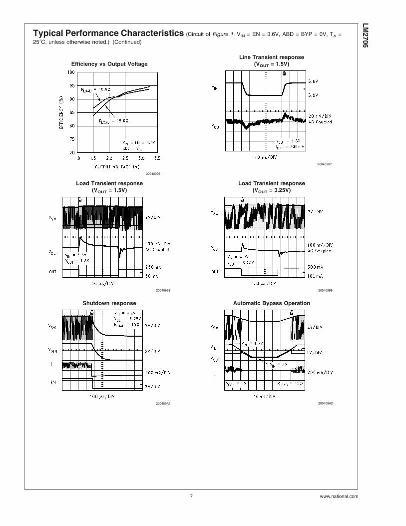
Typical Performance Characteristics (Circuit of Figure 1, VIN = EN = 3.6V, ABD = BYP = 0V, TA =25˚C, unless otherwise noted.) (Continued)
Efficiency vs Output VoltageLine Transient response
(VOUT = 1.5V)
20040996
20040997
Load Transient response(VOUT = 1.5V)
Load Transient response(VOUT = 3.25V)
20040998 20040999
Shutdown response Automatic Bypass Operation
200409A1 200409A2
LM2706
www.national.com7

Typical Performance Characteristics (Circuit of Figure 1, VIN = EN = 3.6V, ABD = BYP = 0V, TA =25˚C, unless otherwise noted.) (Continued)
Forced Bypass Operation Vcontrol Response
200409A3 200409A4
Output Voltage Ripple(VOUT = 1.5V)
Output Voltage Ripple(VOUT = 3.25V)
200409A5 200409A6
Device InformationThe LM2706 is a simple, step-down DC-DC converter andbypass switch optimized for powering RF power amplifiers(PAs) in mobile phones, portable communicators, and similarbattery powered RF devices. It is designed to allow the RFPA to operate at maximum efficiency over a wide range ofpower levels from a single LiION battery cell. It is based ona current-mode buck architecture, with synchronous rectifi-cation for high efficiency. It is designed for a maximum loadcapability of 300 mA. Maximum load range may vary fromthis depending on input voltage, output voltage and theinductor chosen.
The device has all four of the pin-selectable operatingmodes required for powering RF PAs in mobile phones andother sophisticated portable devices with complex powermanagement needs. Fixed-frequency PWM operation offersregulated output at high efficiency while minimizing interfer-ence with sensitive IF and data acquisition circuits. ForcedBypass mode turns on an internal FET bypass switch topower the PA directly from the battery. Automatic Bypassmode turns on the bypass switch when the input voltage getsclose to the set output voltage. This helps the RF poweramplifier maintain its operating power during low batteryconditions by reducing the dropout voltage across theLM2706. Shutdown mode turns the device off and reducesbattery consumption to 0.1 µA (typ).
DC PWM mode output voltage precision is ±2%. Efficiencyis typically around 95% for a 200 mA load with 3.25V output,
3.9V input. The output voltage is dynamically programmablefrom 1.5V to 3.25V by adjusting the voltage on the control pinwithout the need for external feedback resistors. This en-sures longer battery life by being able to change the PAsupply voltage dynamically depending on its transmittingpower.
Additional features include soft-start, current overload pro-tection, over voltage protection and thermal overload protec-tion.
The LM2706 is constructed using a chip-scale 10-pin microSMD package. This package offers the smallest possiblesize, for space-critical applications such as cell phones,where board area is an important design consideration. Useof a high switching frequency (600 kHz) reduces the size ofexternal components. As shown in Figure 1, only three ex-ternal power components are required for implementation.Use of a micro-SMD package requires special design con-siderations for implementation. (See Micro SMD PackageAssembly and Use in the Applications Information section.)Its fine bump-pitch requires careful board design and preci-sion assembly equipment. Use of this package is best suitedfor opaque-case applications, where its edges are not sub-ject to high-intensity ambient red or infrared light. Also, thesystem controller should set EN low during power-up andother low supply voltage conditions. (See Shutdown Mode inthe Device Information section.)
LM27
06
www.national.com 8

Device Information (Continued)
Circuit OperationReferring to Figures 1, 2, 3, the LM2706 operates as follows.During the first part of each switching cycle, the control blockin the LM2706 turns on the internal PFET switch. This allowscurrent to flow from the input through the inductor to theoutput filter capacitor and load. The inductor limits the cur-rent to a ramp with a slope of around (VIN – VOUT)/L, bystoring energy in a magnetic field. During the second part ofeach cycle, the controller turns the PFET switch off, blockingcurrent flow from the input, and then turns the NFET syn-chronous rectifier on. In response, the inductor’s magneticfield collapses, generating a voltage that forces current fromground through the synchronous rectifier to the output filtercapacitor and load. As the stored energy is transferred back
into the circuit and depleted, the inductor current rampsdown with a slope around VOUT/L. If the inductor currentreaches zero before the next cycle, the synchronous rectifieris turned off to prevent current reversal. The output filtercapacitor stores charge when the inductor current is high,and releases it when low, smoothing the voltage across theload.
The output voltage is regulated by modulating the PFETswitch on time to control the average current sent to the load.The effect is identical to sending a duty-cycle modulatedrectangular wave formed by the switch and synchronousrectifier at SW to a low-pass filter formed by the inductor andoutput filter capacitor. The output voltage is equal to theaverage voltage at the SW pin.
20040904
FIGURE 1. Typical Operating Circuit
LM2706
www.national.com9

Circuit Operation (Continued)
PWM OperationWhile in PWM (Pulse Width Modulation) mode, the outputvoltage is regulated by switching at a constant frequencyand then modulating the energy per cycle to control power tothe load. Energy per cycle is set by modulating the PFETswitch on-time pulse-width to control the peak inductor cur-rent. This is done by comparing the signal from the current-sense amplifier with a slope compensated error signal fromthe voltage-feedback error amplifier. At the beginning ofeach cycle, the clock turns on the PFET switch, causing theinductor current to ramp up. When the current sense signalramps past the error amplifier signal, the PWM comparatorturns off the PFET switch and turns on the NFET synchro-nous rectifier, ending the first part of the cycle. If an increasein load pulls the output down, the error amplifier outputincreases, which allows the inductor current to ramp higherbefore the comparator turns off the PFET. This increases theaverage current sent to the output and adjusts for the in-crease in the load.
Before going to the PWM comparator, the error signal issummed with a slope compensation ramp from the oscillatorfor stability of the current feedback loop. During the secondpart of the cycle, a zero crossing detector turns off the NFETsynchronous rectifier if the inductor current ramps to zero.The minimum on time of PFET in PWM mode is 200 ns.
Bypass OperationThe LM2706 contains an internal PFET switch for bypassingthe PWM DC-DC converter during Forced and AutomaticBypass modes. In Forced Bypass mode, this switch is turnedon to power the PA directly from the battery for maximum RFoutput power. Automatic Bypass mode turns on the bypassswitch when the input voltage approaches the programmedoutput voltage so that the RF PA can continue to operatewith good linearity at high power levels when the batteryvoltage is low. When the part operates in the Forced or
20040905
FIGURE 2. Simplified Functional Diagram
200409A7
FIGURE 3. Typical Circuit Waveforms in PWM Mode
LM27
06
www.national.com 10

Bypass Operation (Continued)
Automatic Bypass modes, the output voltage will follow theinput voltage less the voltage drop across the resistance ofthe bypass PFET. These modes are more efficient thanoperating in PWM mode at 100% duty cycle because theresistance of the bypass PFET is less than the series resis-tance of the PWM PFET and inductor. This translates intohigher voltage available on the output in bypass mode, for agiven battery voltage.
The part can be placed in bypass operation by sending BYPpin high for Forced Bypass mode. During Forced Bypassmode, the bypass switch remains on irrespective of the stateof ABD pin. A second way to place the part in bypassoperation is by setting ABD low for Automatic Bypass mode.In Automatic Bypass mode, the bypass switch turns on whenthe difference between the input voltage and programmedoutput voltage is less than 275 mV (typ) for more than thebypass delay time 10 µs (typ). The bypass switch turns offwhen the input voltage is higher than the programmed outputvoltage by 440 mV (typ) for longer than the bypass delaytime. The bypass delay time is provided to prevent falsetriggering into Automatic Bypass Mode modes by eitherspikes or dips in VIN.
Operating Mode Selection ControlsThe LM2706 is designed for digital control of the operatingmodes using BYP and ABD pins. The settings for these pinsare outlined in Table 1. Setting BYP high (>1.2V) places thedevice in Forced Bypass mode. Setting BYP low and ABDhigh forces operation in PWM mode. Setting both BYP andABD low (<0.5V) or leaving them floating places the devicein Automatic Bypass mode. The BYP and ABD pins have5 µA (typ) pull down currents for default operation in Auto-matic Bypass mode for automatic switchover between PWMand Bypass operation in systems where digital mode controlis not required.
TABLE 1. Operating Modes
ModeLogic Level
ABD BYP
Forced Bypass 0 or 1 1
Auto-Bypass / PWM 0 0
PWM 0 or 1 0
Overvoltage ProtectionThe LM2706 has an over-voltage comparator that preventsthe output voltage from rising too high, when the device isleft in PWM mode under low-load conditions. When theoutput voltage rises by 350 mV over its regulation threshold,the OVP comparator inhibits PWM operation to skip pulsesuntil the output voltage returns to the regulation threshold. Inover voltage protection, output voltage and ripple increases.At light loads when the required on time to regulate becomesless than the minimum on time of the LM2706 (around200ns) then the output voltage will increase till it hits theovervoltage threshold and the part will be in overvoltageprotection mode.
Shutdown ModeSetting the EN digital input pin low (<0.5V) places theLM2706 in a 0.1 µA (typ) shutdown mode. During shutdown,
the PFET switch, NFET synchronous rectifier, reference,control and bias circuitry of the LM2706 are turned off.Setting EN high enables normal operation. While turning on,soft start is activated. The device takes around 600 µs tocomplete the soft-start interval and come into regulationduring turn-on.
EN should be set low to turn off the LM2706 during power-upand under voltage conditions when the supply is less thanthe 2.7V minimum operating voltage. The LM2706 is de-signed for compact portable applications, such as mobilephones. In such applications, the system controller deter-mines power supply sequencing and requirements for smallpackage size outweigh the additional size required for inclu-sion of UVLO (Under Voltage Lock-Out) circuitry.
Internal Synchronous RectificationWhile in PWM mode, the LM2706 uses an internal NFET asa synchronous rectifier to reduce rectifier forward voltagedrop and associated power loss. Synchronous rectificationprovides a significant improvement in efficiency wheneverthe output voltage is relatively low compared to the voltagedrop across an ordinary rectifier diode.
During moderate and heavy loads, the internal NFET syn-chronous rectifier is turned on during the inductor currentdown slope during the second part of each cycle. The syn-chronous rectifier is turned off prior to the next cycle, or whenthe inductor current ramps to zero at light loads. The NFETis designed to conduct through it’s intrinsic body diode dur-ing transient intervals before it turns on, eliminating the needfor an external diode.
Current LimitingA current limit feature allows the LM2706 to protect itself andexternal components during overload conditions. In PWMmode a 750 mA max cycle-by-cycle current limit is normallyused.
In the Bypass mode the bypass FET peak current limit is650 mA (typ). During overload conditions the LM2706 limitsoutput current to this value. If the output current reaches thebypass FET peak current limit then the current folds back tothe fold back current value of around 450 mA. A reduction inthe output current below the reset value of around 300 mAresumes normal bypass operation.
In cases where the bypass FET is turned on with a bigdifferential between the input and output voltages the bypassFET may see a peak current exceeding its peak current limitdue to the charging of the output capacitor plus the loadcurrent and will go to the foldback current value thus actingas a constant current source. As the output capacitor getscharged the bypass FET current will go below the reset limitand the bypass switch will be fully on thus acting as a switchagain.
Dynamically Adjustable OutputVoltageThe LM2706 features dynamically adjustable output voltageto eliminate the need for external feedback resistors. Theoutput can be set from 1.5V to 3.25V by changing thevoltage on the analog VCONTROL pin. This feature is useful inPA applications where peak power is needed only when thehandset is far away from the base station or when data isbeing transmitted. In other instances the transmitting powercan be reduced and hence the supply voltage to the PA can
LM2706
www.national.com11

Dynamically Adjustable OutputVoltage (Continued)
be reduced helping maintain longer battery life. See Settingthe Output Voltage in the Application Information section forfurther details.
Soft-StartThe LM2706 has soft start to reduce inrush during power-upand startup. This reduces stress on the LM2706 and externalcomponents. It also reduces startup transients on the powersource. Soft start is implemented by ramping up the refer-ence input to the error amplifier of the LM2706 to graduallyincrease the output voltage. The reference ramps up inaround 600 µs.
Thermal Overload ProtectionThe LM2706 has a thermal overload protection function thatoperates to protect itself from short-term misuse and over-load conditions. When the junction temperature exceedsaround 150˚C, the device initiates a soft-start cycle which iscompleted after the temperature drops below 130˚C. Pro-longed operation in thermal overload conditions may dam-age the device and is considered bad practice.
Application Information
SETTING THE OUTPUT VOLTAGE
The LM2706 features a pin-controlled variable output volt-age to eliminate the need for external feedback resistors.Select an output voltage from 1.5V to 3.25V by setting thevoltage on the VCON output voltage control pin, as directed inTable 2.
When the control pin voltage is between 0.65V and 1.5V, theoutput voltage will vary in a monotonic fashion with respectto the voltage on the control pin as per the above equation.Internally the control pin is buffered and then clamped beforeit is fed to the error amplifier inputs. If voltage on the control
pin is less than 0.55V, the output voltage is regulated at 1.5Vand if the voltage is greater than 1.7V, the output is regulatedat 3.25V.
TABLE 2. Output Voltage Selection
VCON (V) VOUT (V)
VCON ≤ 0.55 1.5
0.65 < VCON < 1.5 VOUT = 1.75 VCON + 0.45V
VCON ≥ 1.7 3.25
Refer to Figure 4 for the relation between VOUT and VCON.
INDUCTOR SELECTION
Use a 10 µH inductor with a saturation current rating ofatleast 750 mA. The inductor’s resistance should be lessthan around 0.3Ω for good efficiency. Table 3 lists suggestedinductors and suppliers.
TABLE 3. Suggested Inductors and Their Suppliers
Part Number Vendor Phone FAX
DO1608C-103 Coilcraft 847-639-6400 847-639-1469
P1174.103T Pulse 858-674-8100 858-674-8262
ELL6RH100M Panasonic 714-373-7366 714-373-7323
CDRH5D18-100 Sumida 847-956-0666 847-956-0702
For low-cost applications, an unshielded bobbin inductor issuggested. For noise critical applications, a toroidal orshielded-bobbin inductor should be used. A good practice isto lay out the board with footprints accommodating bothtypes for design flexibility. This allows substitution of a low-noise toroidal inductor, in the event that noise from low-costbobbin models is unacceptable. The saturation current ratingis the current level beyond which an inductor looses itsinductance. Beyond this rating, the inductor looses its abilityto limit current through the PWM switch to a ramp. This cancause poor efficiency, regulation errors or stress to DC-DCconverters like the LM2706. Saturation occurs when the
magnetic flux density from current through the windings ofthe inductor exceeds what the inductor’s core material cansupport with a corresponding magnetic field.
CAPACITOR SELECTION
Use a 4.7 µF ceramic input capacitor and a 4.7 µF ceramicoutput capacitor. These provide an optimal balance betweensmall size, cost, reliability and performance for cell phonesand similar applications. Table 4 lists suggested capacitorsand suppliers.
200409A9
FIGURE 4. VOUT vs VCON
LM27
06
www.national.com 12

Application Information (Continued)
TABLE 4. Suggested Capacitors and Their Suppliers
Model Type Vendor Phone FAX
4.7 µF for C1, C2 (Input or Output Capacitor)
JMK212BJ475MG Ceramic Taiyo-Yuden 847-925-0888 847-925-0899
LMK316BJ475ML Ceramic Taiyo-Yuden 847-925-0888 847-925-0899
C2012X5R0J475K Ceramic TDK 847-803-6100 847-803-6296
The input filter capacitor supplies current to the PFET switchof the LM2706 in the first part of each cycle and reducesvoltage ripple imposed on the input power source. The out-put filter capacitor smooths out current flow from the inductorto the load, helps maintain a steady output voltage duringtransient load changes and reduces output voltage ripple.These capacitors must be selected with sufficient capaci-tance and sufficiently low ESR to perform these functions.
The ESR, or equivalent series resistance, of the filter capaci-tors is a major factor in voltage ripple. The contribution fromESR to voltage ripple is around 75%–95% for most types ofelectrolytic capacitors, and less for ceramic capacitors. Theremainder of the ripple is from charge storage due to capaci-tance.
OPERATING MODE SELECTION
Drive the ABD and BYP pins using the system controller toset the operating mode of the LM2706. See Table 1 for thepin settings and corresponding operating modes. Use acomparator, Schmitt trigger or logic gate to drive the ABDand BYP pins. Drive the pins below 0.5V for a low logic leveland above 1.2V for a high logic level. In systems whereoperation in Automatic Bypass mode is desired and digitalcontrol of operating modes is unnecessary, connect ABDand BYP to SGND. ABD and BYP have pull-down currentsand will default to Automatic Bypass mode if left floating.
EN PIN CONTROL
Drive the EN pin using the system controller to turn theLM2706 ON and OFF. Use a comparator, Schmitt trigger orlogic gate to drive the EN pin. Set EN high (>1.2V) fornormal operation and low (<0.5V) for a 0.1 µA (typ) shut-down mode.
Set EN low to turn off the LM2706 during power-up andunder voltage conditions when the supply is less than the2.7V minimum operating voltage. The LM2706 is designedfor mobile phones where the system controller controls op-eration mode for maximizing battery life and requirementsfor small package size outweigh the additional size requiredfor inclusion of UVLO (Under Voltage Lock-Out) circuitry.
micro SMD PACKAGE ASSEMBLY AND USE
Use of the micro-SMD package requires specialized boardlayout, precision mounting and careful reflow techniques, asdetailed in National Semiconductor Application Note 1112.Refer to the section Surface Mount Technology (SMT) As-sembly Considerations. For best results in assembly, align-ment ordinals on the PC board should be used to facilitateplacement of the device.
The pad style used with Micro SMD package must be theNSMD (non-solder mask defined) type. This means that thesolder-mask opening is larger than the pad size. This pre-vents a lip that otherwise forms if the solder-mask and pad
overlap, from holding the device off the surface of the boardand interfering with mounting. See Applications Note 1112for specific instructions how to do this.
The 10-Bump package used for the LM2706 has 300 micronsolder balls and requires 10.82 mil pads for mounting on thecircuit board. The trace to each pad should enter the padwith a 90˚ entry angle to prevent debris from being caught indeep corners. Initially, the trace to each pad should be6–7 mil wide, for a section approximately 6 mil long, as athermal relief. Then each trace should neck up or down to itsoptimal width. The important criterion is symmetry. This en-sures the solder bumps on the LM2706 re-flow evenly andthat the device solders level to the board. In particular,special attention must be paid to the pads for bumps 6–8.Because PGND and PVIN are typically connected to largecopper planes, inadequate thermal relief’s can result in lateor inadequate reflow of these bumps.
The micro SMD package is optimized for the smallest pos-sible size in applications with red or infrared opaque cases.Because the micro SMD package lacks the plastic encapsu-lation characteristic of larger devices, it is vulnerable to light.Backside metallization and/or epoxy coating, along withfront-side shading by the printed circuit board, reduce thissensitivity. However, the package has exposed die edges. Inparticular, micro SMD devices are sensitive to light, in thered and infrared range, shining n the package’s exposed dieedges.
Do not use or power-up the LM2706 while subjecting it to redor infrared light otherwise degraded, unpredictable or erraticoperation may result. Examples of light sources with high redor infrared content include the sun and halogen lamps. Pack-age the circuit in a case opaque to red or infrared light.
BOARD LAYOUT CONSIDERATIONS
PC board layout is an important part of DC-DC converterdesign. Poor board layout can disrupt the performance of aDC-DC converter and surrounding circuitry by contributing toEMI, ground bounce, and resistive voltage loss in the traces.These can send erroneous signals to the DC-DC converterIC, resulting in poor regulation or instability. Poor layout canalso result in reflow problems leading to poor solder jointsbetween the Micro SMD package and board pads. Poorsolder joints can result in erratic or degraded performance.
Good layout for the LM2706 can be implemented by follow-ing a few simple design rules.
1. Place the LM2706 on 10.82 mil (10.82/1000 in.) pads. Asa thermal relief, connect to each pad with a 7 mil wide,approximately 7 mil long traces, and then incrementallyincrease each trace to its optimal width. The importantcriterion is symmetry to ensure the solder bumps on theLM2706 re-flow evenly (see Micro SMD Package Assem-bly and Use).
2. Place the LM2706, inductor and filter capacitors closetogether and make the traces short. The traces betweenthese components carry relatively high switching currents
LM2706
www.national.com13

Application Information (Continued)
and act as antennas. Following this rule reduces radiatednoise. Place the capacitors and inductor within 0.2 in(5 mm) of the LM2706.
3. Arrange the components so that the switching currentloops curl in the same direction. During the first half ofeach cycle, current flows from the input filter capacitor,through the LM2706 and inductor to the output filter ca-pacitor and back through ground, forming a current loop.In the second half of each cycle, current is pulled up fromground, through the LM2706 by the inductor, to the outputfilter capacitor and then back through ground, forming asecond current loop. Routing these loops so the currentcurls in the same direction prevents magnetic field rever-sal between the two half-cycles and reduces radiatednoise.
4. Connect the ground pins of the LM2706, and filter capaci-tors together using generous component-side copper fillas a pseudo-ground plane. Then, connect this to theground-plane (if one is used) with several vias. This
reduces ground-plane noise by preventing the switchingcurrents from circulating through the ground plane. It alsoreduces ground bounce at the LM2706 by giving it alow-impedance ground connection.
5. Use wide traces between the power components and forpower connections to the DC-DC converter circuit. Thisreduces voltage errors caused by resistive losses acrossthe traces. Because the FB trace of the LM2706 carriescurrent from the bypass switch, this trace must also bewide.
6. Route noise sensitive traces, such as the voltage feed-back path, away from noisy traces between the powercomponents. The voltage feedback trace must remainclose to the LM2706 circuit and should be routed directlyfrom FB to VOUT at the output capacitor and should berouted opposite to noisy components. This reduces EMIradiated onto the DC-DC converter’s own voltage feed-back trace.
LM27
06
www.national.com 14
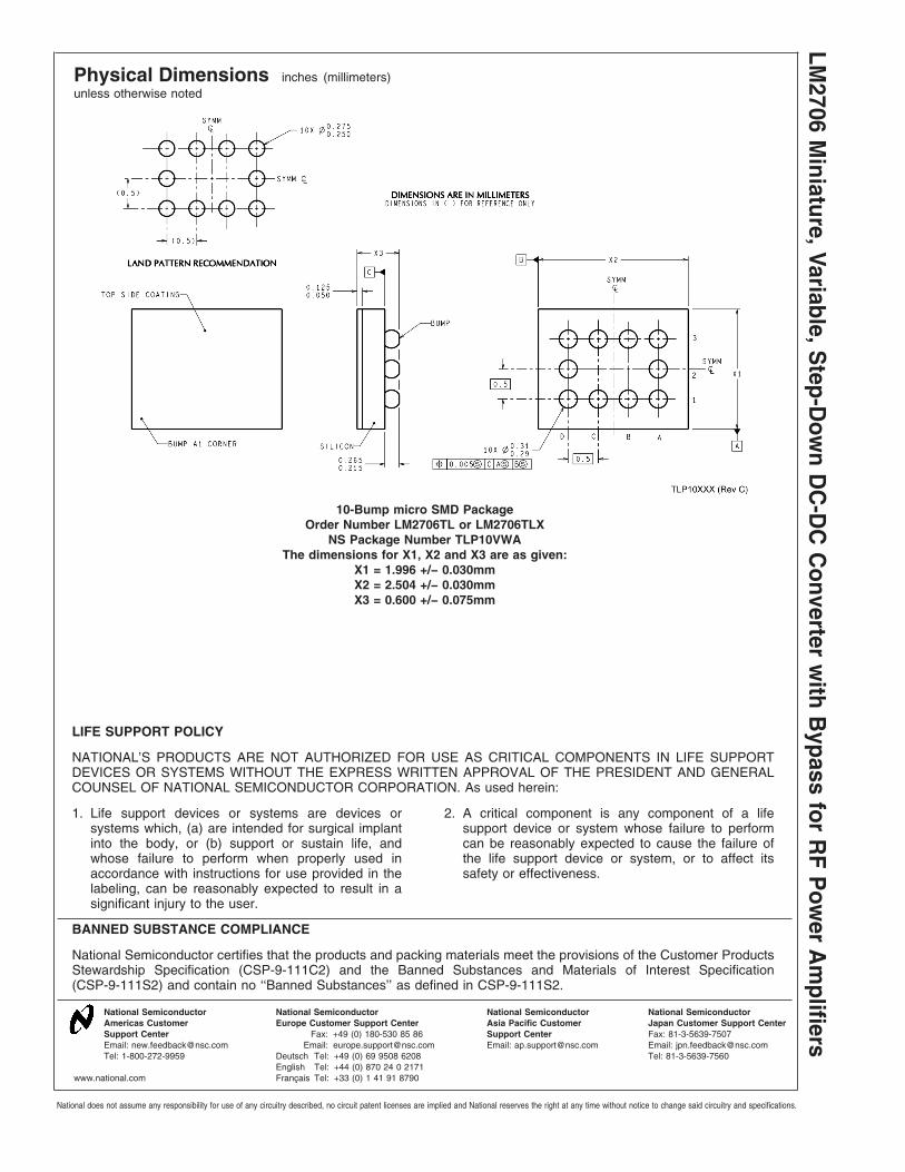
Physical Dimensions inches (millimeters)unless otherwise noted
10-Bump micro SMD PackageOrder Number LM2706TL or LM2706TLX
NS Package Number TLP10VWAThe dimensions for X1, X2 and X3 are as given:
X1 = 1.996 +/− 0.030mmX2 = 2.504 +/− 0.030mmX3 = 0.600 +/− 0.075mm
LIFE SUPPORT POLICY
NATIONAL’S PRODUCTS ARE NOT AUTHORIZED FOR USE AS CRITICAL COMPONENTS IN LIFE SUPPORTDEVICES OR SYSTEMS WITHOUT THE EXPRESS WRITTEN APPROVAL OF THE PRESIDENT AND GENERALCOUNSEL OF NATIONAL SEMICONDUCTOR CORPORATION. As used herein:
1. Life support devices or systems are devices orsystems which, (a) are intended for surgical implantinto the body, or (b) support or sustain life, andwhose failure to perform when properly used inaccordance with instructions for use provided in thelabeling, can be reasonably expected to result in asignificant injury to the user.
2. A critical component is any component of a lifesupport device or system whose failure to performcan be reasonably expected to cause the failure ofthe life support device or system, or to affect itssafety or effectiveness.
BANNED SUBSTANCE COMPLIANCE
National Semiconductor certifies that the products and packing materials meet the provisions of the Customer ProductsStewardship Specification (CSP-9-111C2) and the Banned Substances and Materials of Interest Specification(CSP-9-111S2) and contain no ‘‘Banned Substances’’ as defined in CSP-9-111S2.
National SemiconductorAmericas CustomerSupport CenterEmail: [email protected]: 1-800-272-9959
National SemiconductorEurope Customer Support Center
Fax: +49 (0) 180-530 85 86Email: [email protected]
Deutsch Tel: +49 (0) 69 9508 6208English Tel: +44 (0) 870 24 0 2171Français Tel: +33 (0) 1 41 91 8790
National SemiconductorAsia Pacific CustomerSupport CenterEmail: [email protected]
National SemiconductorJapan Customer Support CenterFax: 81-3-5639-7507Email: [email protected]: 81-3-5639-7560
www.national.com
LM2706
Miniature,Variable,S
tep-Dow
nD
C-D
CC
onverterw
ithB
ypassfor
RF
Pow
erA
mplifiers
National does not assume any responsibility for use of any circuitry described, no circuit patent licenses are implied and National reserves the right at any time without notice to change said circuitry and specifications.