lm961 bluetooth® dual mode module standalone (with...
TRANSCRIPT
Features
Overview
LM961 Bluetooth® Dual Mode ModuleStandalone (With Embedded Bluetooth® v4.1 Stack) Part No (Tray)
Revised
Product
15/DEC/2016
961-0651
Part No (Tape & Reel) 961-0652
LM961
Bluetooth® Dual Mode (Bluetooth® v2.0, v2.1 and Bluetooth® v4.0)
Class 1 Tx Out Power
Low Power Consumption
IC Antenna Onboard
Serial Port Profile (SPP)
Programmable Standalone Module (With Embedded Bluetooth® v4.1 Stack)
Application firmware support
Includes UART to SPP Bridge Application
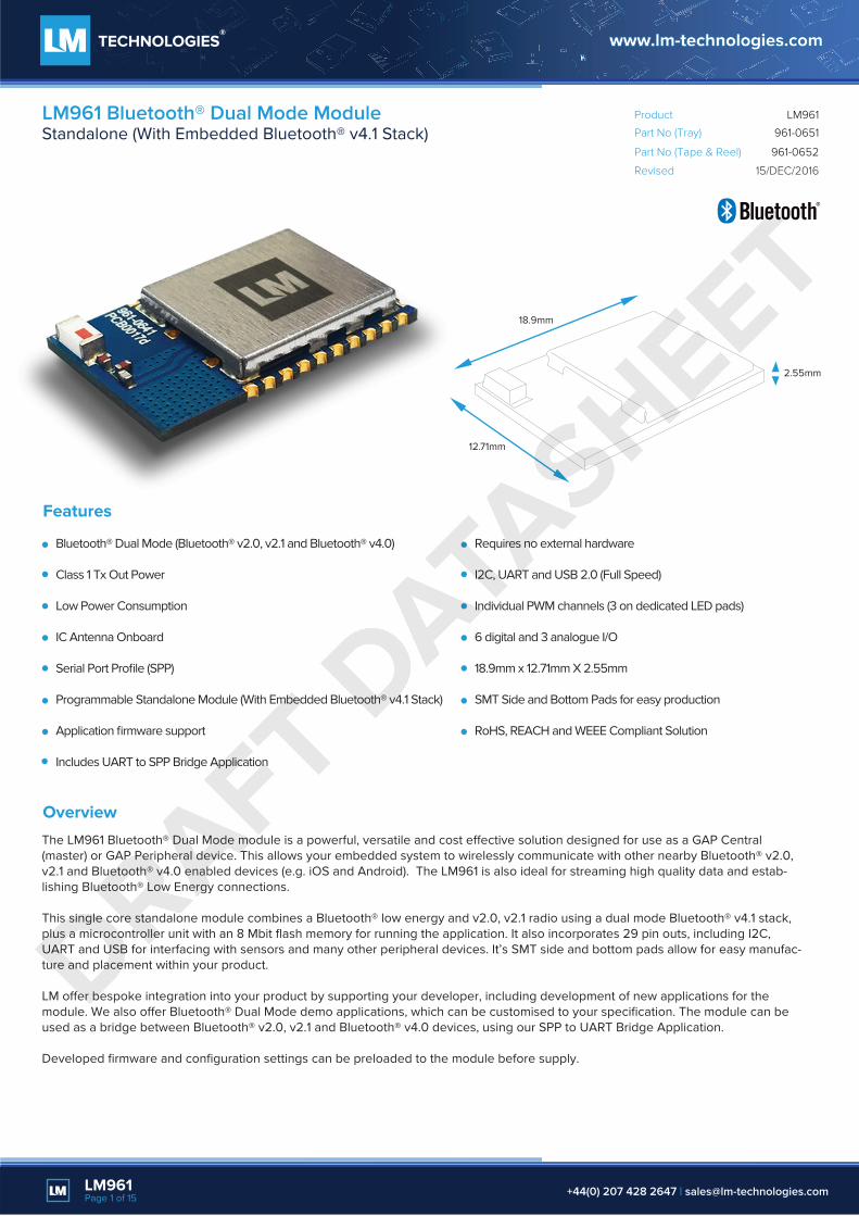
The LM961 Bluetooth® Dual Mode module is a powerful, versatile and cost e�ective solution designed for use as a GAP Central (master) or GAP Peripheral device. This allows your embedded system to wirelessly communicate with other nearby Bluetooth® v2.0, v2.1 and Bluetooth® v4.0 enabled devices (e.g. iOS and Android). The LM961 is also ideal for streaming high quality data and estab-lishing Bluetooth® Low Energy connections.
This single core standalone module combines a Bluetooth® low energy and v2.0, v2.1 radio using a dual mode Bluetooth® v4.1 stack, plus a microcontroller unit with an 8 Mbit flash memory for running the application. It also incorporates 29 pin outs, including I2C, UART and USB for interfacing with sensors and many other peripheral devices. It’s SMT side and bottom pads allow for easy manufac-ture and placement within your product.
LM o�er bespoke integration into your product by supporting your developer, including development of new applications for the module. We also o�er Bluetooth® Dual Mode demo applications, which can be customised to your specification. The module can be used as a bridge between Bluetooth® v2.0, v2.1 and Bluetooth® v4.0 devices, using our SPP to UART Bridge Application.
Developed firmware and configuration settings can be preloaded to the module before supply.
Requires no external hardware
I2C, UART and USB 2.0 (Full Speed)
Individual PWM channels (3 on dedicated LED pads)
6 digital and 3 analogue I/O
18.9mm x 12.71mm X 2.55mm
SMT Side and Bottom Pads for easy production
RoHS, REACH and WEEE Compliant Solution
LM961Page 1 of 15 +44(0) 207 428 2647 | [email protected]
18.9mm
12.71mm
2.55mm
DRAFT DATA
SHEET

Part No (Tray)
Product
961-0651
Part No (Tape & Reel) 961-0652
LM961LM961 Bluetooth® Dual Mode ModuleStandalone (With Embedded Bluetooth® v4.1 Stack)
General Specification
Wireless
Bluetooth® Standard
Module Type
Profiles
v4.1 (Dual Mode)
Standalone (Configurable with AT Commands)
SPP
Hardware
Chipset
Antenna
Microcontroller (MCU)
Flash Memory
RAM
Program Interface
Interfaces
Power Supply
Crystal Oscillators
Development Kit
CSR
IC Antenna Onboard
80 MHz RISC MCU
8 Mbit
56 KB (12K x 24-bit)
SPI
I2C, UART, USB 2.0 (Full Speed), AIO, PIO and PWM
5V (VCHG/ VBUS) or 2V8 (VBAT)
26 MHz
LM55X
RF Characteristics
Tx Output Power
Rx Sensitivity
Data Rate
Frequency
9.4 dBm (Bluetooth® v2.0, v.2.1) and 10 dBm (Bluetooth® v4.0)
-87 dBm (Bluetooth® v2.0, v.2.1) and -92 dBm (Bluetooth® v4.0)
Up to 3Mbps
2.4 GHz to 2.485 GHz
-40°C to +85°C
18.9mm x 12.71mm x 2.55mm
0.84 g
SIG
RoHS, REACH and WEEE
Physical Characteristics
Operating Temperature
Dimensions (L x W x H)
Weight
Certifications
Compliance
LM961Page 2 of 15 +44(0) 207 428 2647 | [email protected]
DRAFT DATA
SHEET

Part No (Tray)
Product
961-0651
Part No (Tape & Reel) 961-0652
LM961LM961 Bluetooth® Dual Mode ModuleStandalone (With Embedded Bluetooth® v4.1 Stack)
Device Settings
Discoverable : YESDevice Name: LM961_PROTO_01Echo of command: YESResponse to commands: YESDefault Security mode 2.1
Bluetooth® Classic Profile Settings
SPP Role : SLAVEEscape sequence check enabled: YES
SSP 2.1 Settings
IoTypesSupported : io capability keyboard onlyForceManInTheMiddle : TRUEDynamicPinEnb: TRUE,
UART Settings Baud rate : 19200 Stop bit : ONEParity bits: NONEFlow Control: None
Bluetooth® Low Energy Settings
GAP Role: CentralGATT ROLE: Client
The LM961 Bluetooth® Dual Mode module is configured by using AT commands in configuration mode. The AT command set controls the primary operations such as information enquiry, connection/ disconnection set up and settings. The LM961 module is configured via its UART interface from a microcontroller or PC, using a MCU software or Hercules SETUP utility respectively. At the start of every power up cycle the LM961 enters the configuration mode.
Please refer to the AT Commands user manuals for the BR/EDR and Bluetooth® low energy connection configurations details:
AT Commands Manual – BR / EDR - http://lm-technologies.com/961atcAT Commands Manual – Bluetooth® low energy connections - http://lm-technologies.com/961atb
AT commands are used to establish BR / EDR and Bluetooth® low energy connections. In data mode, data can be transmitted and received between the Bluetooth® Classic and Bluetooth® v4.0 devices via the LM961 (Bluetooth® Dual Mode Module). By using our SPP to UART Bridge application. And the UART interface represents the data channel once a connection is established. To break the connection and enter the configuration mode again, the LM961 has to be powered o�.
Firmware
Default Factory Settings
LM961Page 3 of 15 +44(0) 207 428 2647 | [email protected]
DRAFT DATA
SHEET

The LM961 module can run full application code for a wide range of industries. This includes the automotive, M2M (industrial cable replacement), EPOS, health & fitness and consumer electronics (e.g. printers and wearable technologies) industries.Only limited by the imagination of the embedded developer. The LM961 modules can run all Bluetooth® applications. Depending on whether the embedded developer requires a low energy Bluetooth® connection, a high-quality data stream Bluetooth® connection or both simultaneously.
LM Technologies o�er both Bluetooth® v4.0 and Bluetooth® Classic application support. This includes assisting the developer and creating new applications with the LM961 modules:
The LM961 module can act as a “bridge” between a Bluetooth® Classic device and a Bluetooth® v4.0 device. By using our Bluetooth® Dual Mode application SPP to UART Bridge. Allowing Bluetooth® Classic data to be transmitted to a Bluetooth® v4.0 device through the LM961 or vice versa
Alert Tag
Key Fob
Beacon
Blood Pressure Sensor
Cycling Speed and Cadence Sensor
Environment Sensor
Glucose Sensor
Health Thermometer
Heart Rate Sensor
Keyboard
Multifunction Steering Wheel
Mouse
Printer
Running Speed and Cadence Sensor
Part No (Tray)
Product
961-0651
Part No (Tape & Reel) 961-0652
LM961LM961 Bluetooth® Dual Mode ModuleStandalone (With Embedded Bluetooth® v4.1 Stack)
Bluetooth® Applications
Example Applicaiton
LM SPP to UART Bridge Application
Security Tag
Serial Communication
Time Client
Temperature and Pressure
Weight Scale
LM961Page 4 of 15 +44(0) 207 428 2647 | [email protected]
UART over GATT: Bluetooth® data to a Bluetooth® v4.0 device, for example our LM931
UART over SPP: Bluetooth® data to a Bluetooth® v2.0 or v2.1 device, for example our LM048
GAP
SMP ATT
GATT
L2CAP
Link Layer
LE PHY
User Application
SPP
RFCOMM
LM048 LM961
CONNECTION A CONNECTION B
LM931
L2CAP
Link Manager
BR/EDR PHY
User Application
X
DRAFT DATA
SHEET

Part No (Tray)
Product
961-0651
Part No (Tape & Reel) 961-0652
LM961LM961 Bluetooth® Dual Mode ModuleStandalone (With Embedded Bluetooth® v4.1 Stack)
LM961Page 5 of 15 +44(0) 207 428 2647 | [email protected]
The SPP to UART Bridge application flow diagram below outlines the steps to setup the “bridge”:
Connection A
Connection B
Note
1. Connection A and Connection B sequence can be interchanged.
2. After Connection A, the device must be in Configuration Mode.
3. The LM961 must enable the Serial CCFG flag on the Bluetooth® low energy Peripheral to transmit data.
4. No specific order is required for disconnection.
Start
Connect to Bluetooth® v2.0, v2.1 device with SPP profile (Master or Slave)
LM961 enters in Configuration Mode
Search Bluetooth® low energy devices
Connect with Bluetooth® low energy device
LM961 scans the services on Bluetooth® low energy device
LM961 scans service for Serial over GATT characteristics
LM961 detects Serial Service writes serial CCFG flag and SPP characteristics
Set the device in “SPPDATAMODE”
LM961 receives data from Bluetooth® low energy/v2.0, v2.1 device & transmits to v2.0, v2.1/Bluetooth® low energy device
Disconnect Bluetooth® v2.0, v2.1 connection
Disconnect Bluetooth® low energy device connection
Stop
DRAFT DATA
SHEET
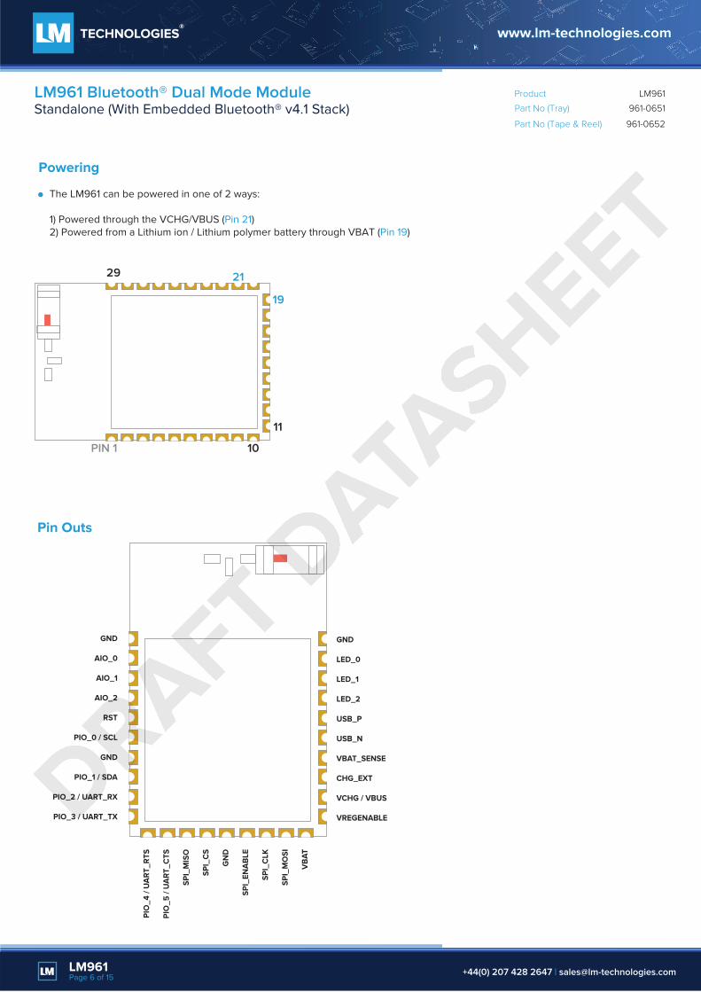
Powering
The LM961 can be powered in one of 2 ways:
1) Powered through the VCHG/VBUS (Pin 21)2) Powered from a Lithium ion / Lithium polymer battery through VBAT (Pin 19)
Pin Outs
Part No (Tray)
Product
961-0651
Part No (Tape & Reel) 961-0652
LM961LM961 Bluetooth® Dual Mode ModuleStandalone (With Embedded Bluetooth® v4.1 Stack)
LM961Page 6 of 15 +44(0) 207 428 2647 | [email protected]
21
19
PIN 1
GND
AIO_0
AIO_1
AIO_2
RST
PIO_0 / SCL
GND
PIO_1 / SDA
PIO_2 / UART_RX
PIO_3 / UART_TX
11
10
29
GND
LED_0
LED_1
LED_2
USB_P
USB_N
VBAT_SENSE
CHG_EXT
VCHG / VBUS
VREGENABLE
PIO
_4 /
UA
RT_R
TS
PIO
_5 /
UA
RT_C
TS
SPI_
MIS
O
SPI_
CS
GN
D
SPI_
ENA
BLE
SPI_
CLK
SPI_
MO
SI
VB
AT
DRAFT DATA
SHEET
Part No (Tray)
Product
961-0651
Part No (Tape & Reel) 961-0652
LM961LM961 Bluetooth® Dual Mode ModuleStandalone (With Embedded Bluetooth® v4.1 Stack)
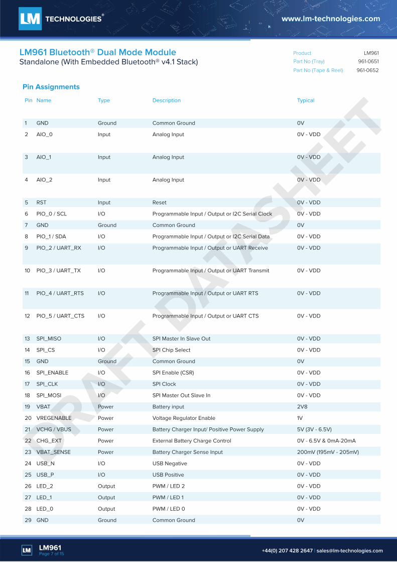
Pin Assignments
Pin
1
2
3
4
5
6
7
8
9
10
11
12
13
14
15
16
17
18
19
20
21
22
23
24
25
26
27
28
29
Name
GND
AIO_0
AIO_1
AIO_2
RST
PIO_0 / SCL
GND
PIO_1 / SDA
PIO_2 / UART_RX
PIO_3 / UART_TX
PIO_4 / UART_RTS
PIO_5 / UART_CTS
SPI_MISO
SPI_CS
GND
SPI_ENABLE
SPI_CLK
SPI_MOSI
VBAT
VREGENABLE
VCHG / VBUS
CHG_EXT
VBAT_SENSE
USB_N
USB_P
LED_2
LED_1
LED_0
GND
Description
Common Ground
Analog Input
Analog Input
Analog Input
Reset
Programmable Input / Output or I2C Serial Clock
Common Ground
Programmable Input / Output or I2C Serial Data
Programmable Input / Output or UART Receive
Programmable Input / Output or UART Transmit
Programmable Input / Output or UART RTS
Programmable Input / Output or UART CTS
SPI Master In Slave Out
SPI Chip Select
Common Ground
SPI Enable (CSR)
SPI Clock
SPI Master Out Slave In
Battery input
Voltage Regulator Enable
Battery Charger Input/ Positive Power Supply
External Battery Charge Control
Battery Charger Sense Input
USB Negative
USB Positive
PWM / LED 2
PWM / LED 1
PWM / LED 0
Common Ground
Typical
0V
0V - VDD
0V - VDD
0V - VDD
0V - VDD
0V - VDD
0V
0V - VDD
0V - VDD
0V - VDD
0V - VDD
0V - VDD
0V - VDD
0V - VDD
0V
0V - VDD
0V - VDD
0V - VDD
2V8
1V
5V (3V - 6.5V)
0V - 6.5V & 0mA-20mA
200mV (195mV - 205mV)
0V - VDD
0V - VDD
0V - VDD
0V - VDD
0V - VDD
0V
Type
Ground
Input
Input
Input
Input
I/O
Ground
I/O
I/O
I/O
I/O
I/O
I/O
I/O
Ground
I/O
I/O
I/O
Power
Power
Power
Power
Power
I/O
I/O
Output
Output
Output
Ground
LM961Page 7 of 15 +44(0) 207 428 2647 | [email protected]
DRAFT DATA
SHEET
Part No (Tray)
Product
961-0651
Part No (Tape & Reel) 961-0652
LM961LM961 Bluetooth® Dual Mode ModuleStandalone (With Embedded Bluetooth® v4.1 Stack)
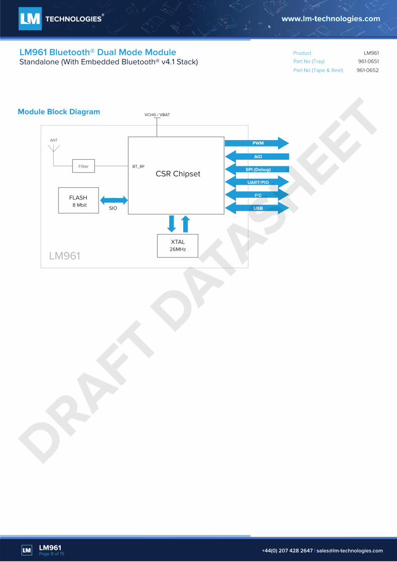
Module Block Diagram
ANT
Filter
XTAL26MHz
CSR Chipset
LM961
BT_RF
UART/PIO
I C2
USB
PWM
AIO
SPI (Debug)
VCHG / VBAT
8 Mbit SIO
FLASH
LM961Page 8 of 15 +44(0) 207 428 2647 | [email protected]
DRAFT DATA
SHEET

Part No (Tray)
Product
961-0651
Part No (Tape & Reel) 961-0652
LM961LM961 Bluetooth® Dual Mode ModuleStandalone (With Embedded Bluetooth® v4.1 Stack)
Physical Dimensions
1.27
1.27
1.27
18.90mm
18.90mm
6.20mm
6.20mm
Pin Spacing
Top View
Side View
Front View
1.981
1.981
0.381mm
1.21mm
4.41mm
0.8mm
Pin 1
Pin 29 20
19
10
2.1mm 2.55mm
2.55mm0.8mm
2.1mm
12.7
1mm
12.71mm
11.5
mm
8.3m
m
LM961Page 9 of 15 +44(0) 207 428 2647 | [email protected]
DRAFT DATA
SHEET
Part No (Tray)
Product
961-0651
Part No (Tape & Reel) 961-0652
LM961LM961 Bluetooth® Dual Mode ModuleStandalone (With Embedded Bluetooth® v4.1 Stack)
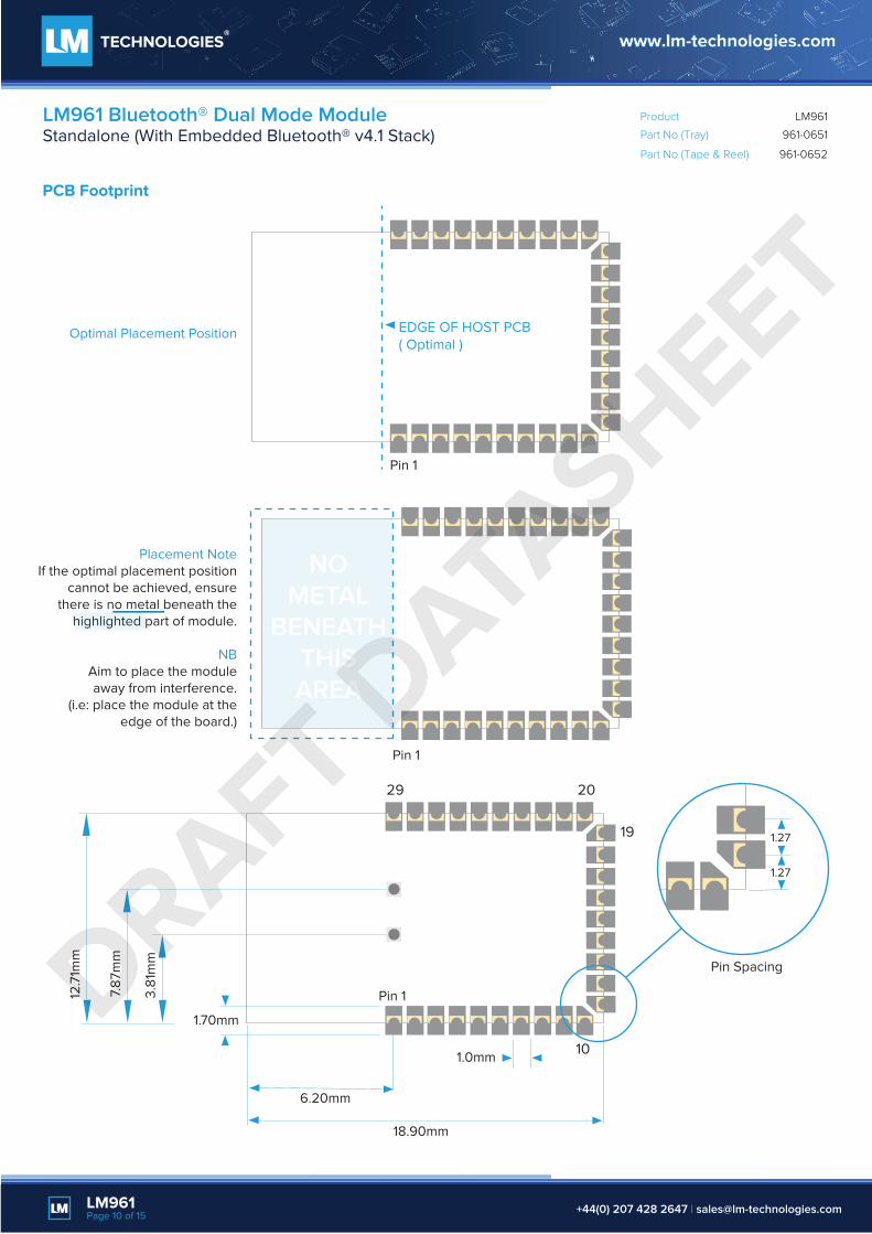
PCB Footprint
1.70mm
1.0mm
1.27
1.27
Pin Spacing
Placement NoteIf the optimal placement position
cannot be achieved, ensurethere is no metal beneath the
highlighted part of module.
NBAim to place the moduleaway from interference.
(i.e: place the module at theedge of the board.)
Optimal Placement Position
Pin 1
Pin 1
Pin 1
18.90mm
6.20mm
12.7
1mm
7.87
mm
3.81
mm
EDGE OF HOST PCB( Optimal )
NOMETAL
BENEATHTHISAREA
2029
19
10
LM961Page 10 of 15 +44(0) 207 428 2647 | [email protected]
DRAFT DATA
SHEET

Part No (Tray)
Product
961-0651
Part No (Tape & Reel) 961-0652
LM961LM961 Bluetooth® Dual Mode ModuleStandalone (With Embedded Bluetooth® v4.1 Stack)
Soldering and Reflow Chart
LM961Page 11 of 15 +44(0) 207 428 2647 | [email protected]
DRAFT DATA
SHEET
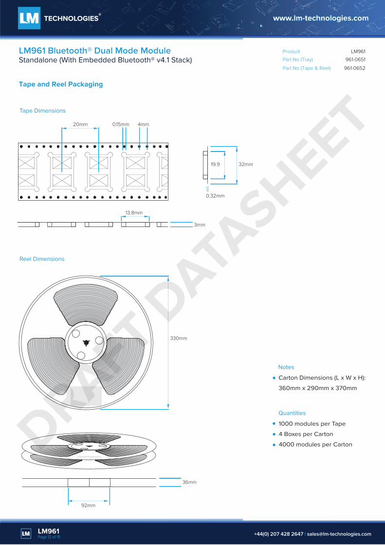
Tape Dimensions
Reel Dimensions
Part No (Tray)
Product
961-0651
Part No (Tape & Reel) 961-0652
LM961LM961 Bluetooth® Dual Mode ModuleStandalone (With Embedded Bluetooth® v4.1 Stack)
Tape and Reel Packaging
LM961Page 12 of 15 +44(0) 207 428 2647 | [email protected]
20mm
19.9 32mm
4mm0.15mm
3mm
0.32mm
13.8mm
330mm
92mm
36mm
1000 modules per Tape
4 Boxes per Carton
4000 modules per Carton
Quantities
Carton Dimensions (L x W x H):
360mm x 290mm x 370mm
Notes
DRAFT DATA
SHEET

Anti-Static PS Tray, Black .
Electrical Resistance: 1 MΩ< R< 100MΩ .
Thickness: T= 0.8 mm
Carton Dimensions (L x W x H):
360mm x 325mm x 160mm
60 modules per Tray
600 modules per Box
4 Boxes per Carton
2400 modules per Carton
Tray Dimensions
Notes Quantities
Part No (Tray)
Product
961-0651
Part No (Tape & Reel) 961-0652
LM961LM961 Bluetooth® Dual Mode ModuleStandalone (With Embedded Bluetooth® v4.1 Stack)
Tray Packaging
LM961Page 13 of 15 +44(0) 207 428 2647 | [email protected]
47.4mm
143mm
10mm
312mm
8.7mm
5mm
6.3mm
13.4mm
6 X 10LM961 LM951
DRAFT DATA
SHEET

Part No (Tray)
Product
961-0651
Part No (Tape & Reel) 961-0652
LM961LM961 Bluetooth® Dual Mode ModuleStandalone (With Embedded Bluetooth® v4.1 Stack)
LM961Page 14 of 15 +44(0) 207 428 2647 | [email protected]
Packaging for Tape & Reel / Tray
)
Model name label
box
carton
carton label
box
drying agentHumidity Indicator Card
Trays are stacked up with an empty tray on the top.
Reels are place within a vacuum bag.
The trays/reels are stacked and inserted into an anti-static vacuum bag and the
Anti-Static Label, Model Name Label and Moisture Sensitive Labels stuck on.
The vacuum bag is placed inside the box and a Model Name Label stuck on the front-side of each box.
Anti-static aluminium vacuum bag.
Anti-static aluminium vacuum bag.
Each carton contains 4 boxes.
DRAFT DATA
SHEET

LM961 Packaging Options
LM961 Module961-06511 x LM961 SMT Plug & Play IC Ant ModuleTray
LM961 Module961-06521 x LM961 SMT Plug & Play IC Ant ModuleTape & Reel
Part No (Tray)
Product
961-0651
Part No (Tape & Reel) 961-0652
LM961LM961 Bluetooth® Dual Mode ModuleStandalone (With Embedded Bluetooth® v4.1 Stack)
LM961Page 15 of 15 +44(0) 207 428 2647 | [email protected]
DRAFT DATA
SHEET