lng tf r110 document final version 6-7-2012 v1
TRANSCRIPT

AGREEMENT
CONCERNING THE ADOPTION OF UNIFORM TECHNICAL PRESCRIPTIONS
FOR WHEELED VEHICLES, EQUIPMENT AND PARTS WHICH CAN BE FITTED AND/OR BE USED ON WHEELED VEHICLES AND THE CONDITIONS FOR RECIPROCAL
RECOGNITION OF APPROVALS GRANTED ON THE BASIS OF THESE PRESCRIPTIONS /
(Revision 2, including the amendments which entered into force on 16 October 1995) _________
Addendum 109: Regulation No. 110
Revision 1
Incorporating all valid text up to: Corrigendum 2 to the original version of the Regulation, subject of Depositary Notification C.N.818.2001.TREATIES-2 dated 23 August 2001 Supplement 1 to the original version of the Regulation - Date of entry into force: 31 January 2003 Supplement 2 to the original version of the Regulation - Date of entry into force: 27 February 2004 Supplement 3 to the original version of the Regulation - Date of entry into force: 12 August 2004 Supplement 4 to the original version of the Regulation - Date of entry into force: 4 July 2006 Supplement 5 to the original version of the Regulation - Date of entry into force: 2 February 2007 Supplement 6 to the original version of the Regulation - Date of entry into force: 18 June 2007 Supplement 7 to the original version of the Regulation - Date of entry into force: 3 February 2008 Supplement 8 to the original version of the regulation – Date of entry into force: 10 August 2010 UNIFORM PROVISIONS CONCERNING THE APPROVAL OF: I. SPECIFIC COMPONENTS OF MOTOR VEHICLES USING COMPRESSED NATURAL GAS (CNG) AND/OR LIQUIFIED NATURAL GAS (LNG) IN THEIR PROPULSION SYSTEM; II. VEHICLES WITH REGARD TO THE INSTALLATION OF SPECIFIC COMPONENTS OF AN APPROVED TYPE FOR THE USE OF COMPRESSED NATURAL GAS (CNG) AND/OR LIQUIFIED NATURAL GAS (LNG) IN THEIR PROPULSION SYSTEM
_________
UNITED NATIONS
/ Former title of the Agreement:
Agreement Concerning the Adoption of Uniform Conditions of Approval and Reciprocal Recognition of Approval for Motor Vehicle Equipment and Parts, done at Geneva on 20 March 1958.
E/ECE/324 E/ECE/TRANS/505 LNG doc. Rev04
06-07-2012

E/ECE/324 E/ECE/TRANS/505 Rev.2/Add.109/Rev.1
Regulation No. 110 page 2
2
Regulation No. 110
UNIFORM PROVISIONS CONCERNING THE APPROVAL OF: I. SPECIFIC COMPONENTS OF MOTOR VEHICLES USING COMPRESSED NATURAL GAS (CNG)
AND/OR LIQUIFIED NATURAL GAS (LNG) IN THEIR PROPULSION SYSTEM; II. VEHICLES WITH REGARD TO THE INSTALLATION OF SPECIFIC COMPONENTS OF AN
APPROVED TYPE FOR THE USE OF COMPRESSED NATURAL GAS (CNG) AND/OR LIQUIFIED NATURAL GAS (LNG) IN THEIR PROPULSION SYSTEM
CONTENTS
REGULATION Page 1. Scope ................................................................................................................................................................. 6 2. References .......................................................................................................................................................... 6 3. Classification of components .......................................................................................................................... 10 4. Definitions ........................................................................................................................................................ 12 PART I 5. Application for approval ................................................................................................................................. 18 6. Markings ......................................................................................................................................................... 18 7. Approval ......................................................................................................................................................... 19 8. Specifications regarding CNG/LNG components ........................................................................................... 20 9. Modifications of a type of CNG/LNG component and extension of approval ................................................ 21 10. (Not allocated) ................................................................................................................................................ 22 11. Conformity of production ................................................................................................................................ 22 12. Penalties for non-conformity of production .................................................................................................... 22 13. (Not allocated) ................................................................................................................................................. 22 14. Production definitely discontinued .................................................................................................................. 22 15. Names and addresses of Technical Services Responsible for conducting approval tests,
and of Administrative Departments ................................................................................................................. 23
PART II 16. Application for approval ................................................................................................................................. 24 17. Approval .......................................................................................................................................................... 24 18. Requirements for the installation of specific components for the use of compressed natural gas and/or
liquefied natural gas in the propulsion system of a vehicle ............................................................................. 26 19. Conformity of production ................................................................................................................................ 32 20. Penalties for non-conformity of production .................................................................................................... 32 21. Modification and extension of approval of a vehicle type ............................................................................... 32 22. Production definitely discontinued .................................................................................................................. 33 23. Names and addresses of Technical Services responsible for conducting approval tests,
and of Administrative Departments ................................................................................................................. 33 ANNEXES Annex 1A - Essential characteristics of the CNG / LNG component Annex 1B - Essential characteristics of the vehicle, engine and CNG/LNG-related system Annex 2A - Arrangement of the CNG/LNG component type-approval mark Annex 2B - Communication concerning the approval or extension or refusal or withdrawal of approval or
production definitely discontinued of a type of CNG/LNG component pursuant to Regulation No. 110
Addendum - Additional information concerning the type-approval of a type of CNG/LNG components pursuant
to Regulation No. 110 Annex 2C - Arrangement of approval marks Annex 2D - Communication concerning the approval or extension or refusal or withdrawal of approval or
production definitely discontinued of a vehicle type with regard to the installation of CNG/LNG system pursuant to Regulation No. 110
Annex 3 - On board storage of natural gas as a fuel for automotive vehicles. Annex 3A - Gas cylinders - High pressure cylinder for the on-board storage of CNG (compressed natural gas)
as a fuel for automotive vehicles
Annex 3A - Appendix A - Test methods Annex 3A - Appendix B - Not allocated) Annex 3A - Appendix C - (Not allocated) Annex 3A - Appendix D - Report Forms Annex 3A - Appendix E - Verification of stress ratios using strain gauges Annex 3A - Appendix F - Fracture performance methods

E/ECE/324 E/ECE/TRANS/505 Rev.2/Add.109/Rev.1
Regulation No. 110 page 4
4
Annex 3A - Appendix G - Instructions by the container manufacturer regarding
handling, use and inspection of cylinders Annex 3A - Appendix H - Environmental test
Annex 3B - Liquid tanks - Vacuum insulated vessels for the on-board storage of LNG (liquefied natural
gas) as a fuel for automotive vehicles - Annex 3B - Appendix A - Test methods - Annex 3B - Appendix B - Report forms - Annex 3B - Appendix C - Instructions by the container manufacturer regarding
handling, use and inspection of cylinders - Annex 3B - Appendix D - Report form (not mandatory) Annex 4A - Provisions regarding the approval of the automatic valve, non-return valve, the pressure relief
valve, pressure relief device and the excess flow valve for CNG applications Annex 4B - Provisions regarding the approval of flexible fuel lines or hoses for CNG applications Annex 4C - Provisions regarding the approval of the CNG filter Annex 4D - Provisions regarding the approval of the CNG pressure regulator Annex 4E - Provisions regarding the approval of the CNG pressure and temperature sensors Annex 4F - Provisions regarding the approval of the CNG filling unit Annex 4G - Provisions regarding the approval of the CNG gas flow adjuster and gas/air mixer or injector
Annex 4H - Provisions regarding the approval of the electronic control unit for CNG/LNG applications. Annex 4I - Provisions regarding the approval of the LNG heat exchanger – vaporizer Annex 4J - Provisions regarding the approval of the LNG filling receptacle Annex 4K - Provisions regarding the approval of the LNG pressure control regulator Annex 4L Provisions regarding the approval of the LNG pressure and/or temperature sensor Annex 4M - Provisions regarding the approval of the LNG natural gas detector Annex 4N - Provisions regarding the approval of the automatic valve, check valve, pressure relief valve, excess
flow valve, manual valve and non-return valve for LNG applications. Annex 4O - Provisions regarding the approval of the LNG fuel pump Annex 5 - Test procedures Annex 5A - Overpressure test (Strength test) Annex 5B - External leakage test Annex 5C - Internal leakage test
Annex 5D - CNG/LNG compatibility test Annex 5E - Corrosion resistance test Annex 5F - Resistance to dry heat Annex 5G - Ozone ageing Annex 5H - Temperature cycle test Annex 5I - Pressure cycle test applicable only to cylinders (see Annex 3A) Annex 5J - (Not allocated) Annex 5K - (Not allocated) Annex 5L - Durability test (Continued operation) Annex 5M - Burst/destructive test applicable only to cylinders (see Annex 3A) Annex 5N - Vibration resistance test Annex 5O - Operating temperatures Annex 5P - LNG - low temperature test (below -40°C) Annex 6 - Provisions regarding CNG identification mark for public service vehicles Annex 7 - Provisions regarding LNG identification mark for public service vehicles

E/ECE/324 E/ECE/TRANS/505 Rev.2/Add.109/Rev.1
Regulation No. 110 page 6
6
1. SCOPE This Regulation applies to: 1.1. Part I. Specific components for vehicles of category M and N 1/ using
compressed natural gas (CNG) and/or liquefied natural gas (LNG) in their propulsion system;
1.2. Part II. Vehicles of category M and N 1/ with regard to the installation of specific
components, for the use of compressed natural gas (CNG) and/or liquefied natural gas (LNG) for propulsion, of an approved type.
2. REFERENCES The following standards contain provisions that, through reference in this text, constitute provisions of this regulation.
ASTM Standards 2/ ASTM B117-90 Test method of Salt Spray (Fog) Testing, ASTM B154-92 Mercurous Nitrate Test for Copper and Copper Alloys ASTM D522-92 Mandrel Bend Test of attached Organic Coatings; ASTM D1308-87 Effect of Household Chemicals on Clear and Pigmented Organic
Finishes; ASTM D2344-84 Test Method for Apparent interlaminar Shear Strength of Parallel
Fiber Composites by Short Beam Method; ASTM D2794-92 Test Method for Resistance of Organic Coatings to the Effects of
Rapid Deformation (Impact); ASTM D3170-87 Chipping Resistance of Coatings; ASTM D3418-83 Test Method for Transition Temperatures Polymers by Thermal
Analysis; ASTM E647-93 Standard Test, Method for Measurement of Fatigue Crack Growth
Rates; ASTM E813-89 Test Method for JIC, a Measure of Fracture Toughness;
1/ As defined in Annex 7 to the Consolidated Resolution on the Construction of Vehicles (R.E.3), (document TRANS/WP.29/78/Rev.1/Amend.2, as last amended by Amend.4).
2/ American Society for Testing and Materials.

ASTM G53-93 Standard Practice for Operating Light and Water - Exposure Apparatus (Fluorescent UV-Condensation Type) for Exposure of non-metallic materials
BSI Standards 3/ BS 5045: Part 1 (1982) Transportable Gas Containers - Specification for
Seamless Steel Gas Containers Above 0.5 litre Water Capacity BS 7448-91 Fracture Mechanics Toughness Tests Part I - Method for
Determination of KIC, Critical COD and Critical J Values of BS PD 6493-1991.Guidance an Methods for Assessing the A Acceptability of Flaws in Fusion Welded Structures; Metallic Materials
EN Standards 4/ EN 13322-2 2003 Transportable gas cylinders – Refillable welded steel gas cylinders -
Design and construction – Part 2: Stainless steel EN ISO 5817 2003 Arc-welded joints in steel; guidance on quality levels for
imperfections EN1251-2 2000 Cryogenic vessels. Vacuum insulated vessels of not more than 1000
liters volume. EN 895:1995 Destructive tests on welds in metallic materials. Transverse
tensile test.
EN 910:1996 Destructive test methods on welds in metallic materials. Bend tests.
EN 1435:1997 Non-destructive examination of welds. Radiographic
examination of welded joints. EN 6892-1:2009 Metallic materials. Tensile test.
EN 10045-1:1990 Charpy impact test on metallic materials. Test method (V- and U-notches).
ISO Standards 5/ ISO 148-1983 Steel - Charpy Impact Test (v-notch); ISO 306-1987 Plastics - Thermoplastic Materials - Determination of Vicat
Softening Temperature; ISO 527 Pt 1-93 Plastics - Determination of Tensile Properties - Part I: General
principles;
3/ British Standards Institution.
4/ European Norm
5/ International Organization for Standardization.

E/ECE/324 E/ECE/TRANS/505 Rev.2/Add.109/Rev.1
Regulation No. 110 page 8
8
ISO 642-79 Steel-Hardenability Test by End Quenching (Jominy Test); ISO 2808-91 Paints and Varnishes - Determination of film Thickness; ISO 3628-78 Glass Reinforced Materials - Determination of Tensile Properties ISO 4624-78 Plastics and Varnishes - Pull-off Test for adhesion; ISO 6982-84 Metallic Materials - Tensile Testing, ISO 6506-1981 Metallic Materials - Hardness test - Brinell Test; ISO 6508-1986 Metallic Materials - Hardness Tests - Rockwell Test (Scales,
ABCDEFGHK); ISO 7225 Precautionary Labels for Gas Cylinders, ISO/DIS 7866-1992 Refillable Transportable Seamless Aluminum Alloy Cylinders for
Worldwide Usage Design, Manufacture and Acceptance; ISO 9001:1994 Quality Assurance in Design/Development. Production, Installation
and Servicing; ISO 9002:1994 Quality Assurance in Production and Installation; ISO/DIS 12737 Metallic Materials - Determination of the Plane-Strain Fracture
Toughness; ISO12991 Liquefied natural gas (LNG) – transportable tanks for use on board
vehicles; ISO14469-1:2004 Road Vehicles: compressed natural gas CNG refueling connector:
part 1: 20Mpa (200 bar) connector; ISO14469-2:2007 Road Vehicles: compressed natural gas CNG refueling connector:
part 2: 20MP (200 bar) connector; ISO 21028-1:2004 Cryogenic vessels -- Toughness requirements for materials at
cryogenic temperature -- Part 1: Temperatures below -80 degrees C ISO 21029-1:2004 Cryogenic vessels -- Transportable vacuum insulated vessels of not
more than 1 000 litres volume -- Part 1: Design, fabrication, inspection and tests
ISO/IEC Guide 25-1990 General requirements for the Technical Competence of Testing
Laboratories; ISO/IEC Guide 48-1986 Guidelines for Third Party Assessment and Registration of Supplies
Quality System; ISO/DIS 9809 Transportable Seamless Steel Gas Cylinders Design, Construction
and Testing - Part I: Quenched and Tempered Steel Cylinders with Tensile Strength < 1100 MPa;


E/ECE/324 E/ECE/TRANS/505 Rev.2/Add.109/Rev.1
Regulation No. 110 page 10
10
NACE Standard 6/ NACE TM0177-90 Laboratory Testing of Metals for Resistance to Sulphide Stress
Cracking in H2S Environments.
ECE Regulations 7/
ECE Regulation 10 Uniform provisions concerning the approval of vehicles with regard
to electromagnetic compatibility
USA Federal Regulations 8/ 49 CFR 393.67 Liquid fuel tanks. SAE Standards 9/ SAE J2343-2008 Recommended Practice for LNG Medium and Heavy-Duty
Powered Vehicles
6/ National Association of Corrosion Engineers.
7/ United Nations regulations
8/ USA Federal Regulations
9/ Society of Automotive Engineers

3 CLASSIFICATION OF COMPONENTS CNG and/or LNG components for use in vehicles shall be classified with regard to the working pressure, temperature and function, according to figure 1-1.
START
In contact with gas
temperature <-40°C
450<p0<3000 kPa
Safety valve
Class 1
Class 3
Class 2
Class 5
Class 4
Class 0
Not subject to this Regulation
P0<26000 kPa
NO
NO
NO
NO
NO
NO
YES
YES
NO YES
YES
YES
YES
YES
P0>3000 kPa
20<p0<450 kPa

E/ECE/324 E/ECE/TRANS/505 Rev.2/Add.109/Rev.1
Regulation No. 110 page 12
12
Class 0 High pressure parts including tubes and fittings containing CNG at a pressure higher
than 3 MPa and up to 26 MPa. Class 1 Medium pressure parts including tubes and fittings containing CNG at a pressure higher
than 450 kPa and up to 3,000 kPa (3 MPa). Class 2 Low pressure parts including tubes and fittings containing CNG at a pressure higher
than 20 kPa and up to 450 kPa. Class 3 Medium pressure parts as safety valves or protected by safety valve including tubes and
fittings containing CNG at a pressure higher than 450 kPa and up to 3,000 kPa (3 MPa). Class 4 Parts in contact with gas subject to the pressure lower than 20 kPa. Class 5 Parts in contact with temperature range extending below -40°C A component can consist of several parts, each part classified in its own class with regard to maximum working pressure and function.
Fig. 1-2
Tests applicable to specific classes of components
(Excluding CNG cylinders and LNG cryogenic tank)
Performance Test
Over-
pressure Strength
Test
Leakage
Test (external)
Leakage
Test (internal)
Continued Operation Durability
Test
Corrosion Resistance
Ozone Ageing
CNG/LNG
Compatibility
Vibration Resistance
Dry - Heat Resistance
Low Temperatu
re test (<-40°C)
Annex
5A
Annex 5B
Annex 5C
Annex 5L
Annex 5E
Annex
5G
Annex 5D
Annex 5N
Annex 5F
Annex 5P
Class 0
X
X
A
A
X
X
X
X
X
O
Class 1
X
X
A
A
X
X
X
X
X
O
Class 2
X
X
A
A
X
A
X
X
A
O
Class 3
X
X
A
A
X
X
X
X
X
O
Class 4
O
O
O
O
X
A
X
O
A
O
Class 5
X
A
A
A
A
A
A
A
A
X
X = Applicable O = Not applicable A = As applicable

4. DEFINITIONS 4.1. "Pressure" means relative pressure versus atmospheric pressure, unless otherwise stated. 4.2 "Service pressure" means the settled pressure at a uniform gas temperature of 15 C. 4.3 "Test pressure" means the pressure to which a component is taken during acceptance testing. For
LNG tank, the economizer pressure setting, or normal saturation pressure of LNG required by the engine. For the CNG cylinder the pressure at which the cylinder is hydrostatically tested.
4.4. "Working pressure" means the maximum pressure to which a component is designed to be subjected
to and which is the basis for determining the strength of the component under consideration. For CNG cylinder, the settled pressure of 20 MPa at a uniform temperature of 15 C. For LNG tank,
the pressure of the LNG tank primary relief valve setting. 4.5. "Operating temperatures" means maximum values of the temperature ranges, indicated in Annex 5O,
at which safe and good functioning of the specific component is ensured and for which it has been designed and approved.
4.6. "Specific component" means:
(a) container (cylinder or tank), (b) accessories fitted to the container (c) pressure regulator, (d) automatic valve, (e) manual valve, (f) gas supply device, (g) gas flow adjuster, (h) flexible fuel line for CNG (i) rigid fuel line, (j) filling unit or receptacle, (k) non-return valve or check valve, (l) pressure relief valve (discharge valve) primary and secondary, (m) pressure relief device (temperature triggered), (n) filter, (o) pressure or temperature sensor / indicator, (p) excess flow valve, (q) service valve, (r) electronic control unit, (s) gas-tight housing, (t) fitting, (u) ventilation hose. (v) pressure relief device (PRD)(pressure triggered). (w) heat exchanger/vaporizer (x) natural gas detector (y) fuel pump (for LNG)
4.7. “multi-functional component” means any of the above mentioned specific components combined or
fitted together as a " component".

E/ECE/324 E/ECE/TRANS/505 Rev.2/Add.109/Rev.1
Regulation No. 110 page 14
14
4.8. "Approval of a vehicle" means the approval of a vehicle type of categories M and N with regard to its
CNG and/or LNG system as original equipment for the use in its propulsion system; 4.9 "Vehicle type" means vehicles fitted with specific components for the use of CNG and/or LNG in
their propulsion system which do not differ with respect to the following conditions: 4.9.1. the manufacturer; 4.9.2. the type designation established by the manufacturer, 4.9.3. the essential aspects of design and construction: 4.9.3.1. chassis/floor pan (obvious and fundamental differences); 4.9.3.2. the installation of the CNG and/or LNG equipment (obvious and fundamental differences). 4.10 "CNG system" means an assembly of components (container(s) or cylinder(s), valves, flexible fuel
lines, etc.) and connecting parts (rigid fuel lines, pipes fitting, etc.) fitted on motor vehicles using CNG in their propulsion system.
4.11 “LNG system” means an assembly of components (tanks, valves, flexible fuel lines, etc.) and
connecting parts (fuel lines, fittings, etc.) fitted on motor vehicles using LNG in their propulsion system and related components up to and including the vaporizer. Other parts downstream from the LNG system from the vaporizer will conform to the CNG system.
4.12 "Container" (or cylinder) means any storage system used for compressed natural gas 4.13 "Type of container" means containers which do not differ in respect of the dimensional and material
characteristics as specified in Annex 3A.
4.13.1. .A container can be:
CNG-1 metal; CNG-2 metal liner reinforced with resin impregnated continuous filament (hoop wrapped); CNG-3 metal liner reinforced with resin impregnated continuous filament (fully wrapped); CNG-4 resin impregnated continuous filament with a non-metallic liner (all composite).
4.14. “Tank” (or vessel) means any storage system used for liquefied natural gas 4.15. "Type of tank" means tanks which do not differ in respect of the dimensional and material
characteristics as specified in Annex 3B. 4.16. "Accessories fitted to the container or tank" means the following components (but not limited to
them), either separate or combined, when fitted to the container or tank: 4.16.1. “Manual valve”; valve which is operated manually
4.16.2. “Pressure sensor/indicator”; means a pressurized device which indicates the gas or liquid pressure; 4.16.3. “Excess flow valve”; valve which automatically shuts off, or limits, the gas flow when the flow
exceeds a set design value 4.16.4. “Gas-tight housing”. Means a device that vents gas leakage to outside the vehicle including the gas
ventilation hose. 4.17. "Valve" means a device by which the flow of a fluid may be controlled. 4.18. "Automatic valve" means a valve which is not operated manually. 4.19 "Automatic cylinder valve" means an automatic valve rigidly fixed to the cylinder which controls the
flow of gas to the fuel system. The automatic cylinder valve is also called remote-controlled service valve.
4.20. "Non-return valve or check valve" means an automatic valve that allows gas/fluid to flow in only
one direction. 4.21 "Excess flow valve" (excess flow limiting device) means a device which automatically shuts off, or
limits, the gas or liquid flow when the flow exceeds a set design value. 4.22 "Manual valve" means a manual valve rigidly fixed to the cylinder or tank. 4.23 "Pressure relief valve (discharge valve)" means a device which prevents a pre-determined upstream
pressure being exceeded. 4.24. "Service valve" means an isolation valve which is closed only when servicing the vehicle. 4.25 "Filter" means a protective screen which removes foreign debris from the gas or liquid stream. 4.26 "Fitting" means a connector used in a piping, tubing, or hose system. 4.27 “LNG fuel pump” means a device to establish the supply of LNG to the engine by increasing the
pressure of the fluid (liquid or vapour). 4.28 "Flexible fuel lines" means flexible tubing or hose through which natural gas flow. 4.29 "Rigid fuel lines" means tubing which has not been designed to flex in normal operation and through
which natural gas flows. 4.30. "Gas supply device" means a device for introducing gaseous fuel into the engine intake manifold
(carburetor or injector). 4.31 "Gas/air mixer" means a device for mixing the gaseous fuel and intake air for the engine. 4.32 "Gas injector" means a device for introducing gaseous fuel into the engine or associated intake
system. 4.33 "Gas flow adjuster" means a gas flow restricting device, installed downstream of a pressure regulator,
controlling gas flow to the engine .4.34 "Pressure regulator" means a device used to control the pressure;
E/ECE/324 E/ECE/TRANS/505 Rev.2/Add.109/Rev.1
Regulation No. 110 page 16
16
4.35 "Pressure relief device (PRD) (temperature triggered)" means a one time use device triggered by
excessive temperature and/or pressure which vents gas to protect the cylinder from rupture. 4.36 “Pressure relief device (PRD) (pressure triggered) (this device sometimes is referred to as “burst
disc”)”means a one time use device triggered by excessive pressure which prevents a pre-determined upstream pressure being exceeded.
4.37. "Filling unit or receptacle" means a device fitted in the vehicle used to fill the container or tank in the
filling station. 4.38 "Electronic control unit (CNG - fuelling)" means a device which controls the gas demand of the
engine, and other engine parameters, and cuts off automatically the automatic valve, required by safety reason.
4.39. "Type of components" as mentioned in paragraphs 4.17. to 4.37. above means components that do not
differ in such essential respect as materials, working pressure and operating temperatures. 4.40 "Type of electronic control unit" as mentioned in paragraph 4.38. means components that do not
differ in such essential respect as the basic software principles excluding minor changes. 4.41 “Heat exchanger/Vaporizer” a heater used to change the state of LNG into CNG. 4.42 “Liquefied Natural Gas (LNG)” “also called Liquid Natural Gas” is a cryogenic liquid produced
by reducing the temperature of natural gas to about -161.7°C at atmospheric pressure and stored for use as a vehicle fuel.
4.43 ”Compressed Natural Gas (CNG)” is natural gas that has been compressed and stored for use as a
vehicle fuel
4.44 “Boil-off” gas created by evaporation of LNG due to ambient heat input. 4.45 “Venting” The discharge of vapours out of the storage container/tank. 4.46 “Venting management system ” is a system that controls the release of natural gas from the LNG
storage system.
4.47 ”auto-frettage”: A pressure application procedure used in manufacturing composite cylinders with metal liners, which strains the liner past its limit of elasticity, sufficiently to cause permanent plastic deformation which results in the liner having compressive stresses and the fibers having tensile stresses at zero internal pressure.
4.48. “auto-frettage pressure”: The pressure within the over-wrapped cylinder at which the required
distribution of stresses between the liner and the over-wrap is established. 4.49 “batch - composite cylinders”: A "batch" shall be a group of cylinders successively produced from
qualified liners having the same size, design, specified materials of construction and process of manufacture.
4.50 “batch - metal cylinders and liners”: A "batch" shall be a group of metal cylinders or liners
successively produced having the same nominal diameter, wall thickness, design, specified material of construction, process of manufacture, equipment for manufacture and heat treatment, and conditions of

time, temperature and atmosphere during heat treatment;
4.51 “batch non-metallic liners”: A "batch" shall be a group of non-metallic liners successively produced having the same nominal diameter, wall thickness, design specified material of construction and process of manufacture;
4.52 “batch limits”: In no case shall a "batch" be permitted to exceed 200 finished cylinders or liners (not including
destructive test cylinders or liners), or one shift of successive production, whichever is greater. 4.53 “composite cylinder”: A cylinder made of resin impregnated continuous filament wound over a metallic or non-
metallic liner. Composite cylinders using non-metallic liners are referred to as all-composite cylinders. 4.54 “controlled tension winding”: A process used in manufacturing hoop wrapped composite cylinders with metal
liners by which compressive stresses in the liner and tensile stresses in the over-wrap at zero internal pressure are obtained by winding the reinforcing filaments under significant high tension.
4.55. “filling pressure”: The gas pressure in the cylinder immediately upon completion of filling. 4.56 “finished cylinders”: Completed cylinders which are ready for use, typical of normal production, complete with
identification marks and external coating including integral insulation specified by the manufacturer, but free from non-integral insulation or protection.
4.57 “full-wrap”: An over-wrap having a filament wound reinforcement both in the circumferential and axial direction
of the cylinder. 4.58 “gas temperature”: The temperature of gas in a cylinder. 4.59 “hoop-wrap”: An over-wrap having a filament wound reinforcement in a substantially circumferential pattern
over the cylindrical portion of the liner so that the filament does not carry any significant load in a direction parallel to the cylinder longitudinal axis.
4.60 “liner”: A container that is used as a gas-tight, inner shell, on which reinforcing fibers are filament wound to
reach the necessary strength. Two types of liners are described in this standard: Metallic liners that are designed to share the load with the reinforcement, and non-metallic liners that do not carry any part of the load.
4.61 “manufacturer”: The person or organization responsible for the design, fabrication and testing of CNG or LNG
specific components. 4.62 “maximum developed pressure”: The settled pressure developed when gas in a cylinder filled to the working
pressure is raised to the maximum service temperature. 4.63 “over-wrap”: The reinforcement system of filament and resin applied over the liner. 4.64 “pre-stressing”: The process of applying auto-frettage or controlled tension winding. 4.65 “service life”: The life in years during which the cylinders may safely be used in accordance with the standard
service conditions. 4.66 “settled pressure”: The gas pressure when a given settled temperature is reached. 4.67 “settled temperature”: The uniform gas temperature after any change in temperature caused by filling has
dissipated.
4.70. “LNG trapping” is containment of LNG in an enclosure of constant volume).

E/ECE/324 E/ECE/TRANS/505 Rev.2/Add.109/Rev.1
Regulation No. 110 page 18
18
4.71 “Cryogenic temperature” for the purpose of this regulation Cryogenic means temperatures below -40°C.

PART I APPROVAL OF SPECIFIC COMPONENTS OF MOTOR VEHICLES USING COMPRESSED NATURAL GAS (CNG) AND/OR LIQUIFIED NATURAL GAS (LNG) IN THEIR PROPULSION SYSTEM 5. APPLICATION FOR APPROVAL 5.1. The application for approval of specific component or multifunctional component shall be submitted
by the holder of the trade name or mark or by his duly accredited representative. 5.2 It shall be accompanied by the under-mentioned documents in triplicate and by the following
particulars: 5.2.1. Description of the vehicle comprising all the relevant particulars referred to in Annex 1A to this
Regulation, 5.2.2. A detailed description of the type of the specific component or multifunctional component 5.2.3. A drawing of the specific component or multifunctional component, sufficiently detailed and on an
appropriate scale, 5.2.4. Verification of compliance with the specifications prescribed in paragraph 8. of this Regulation. 5.3. At the request of the Technical Service responsible for conducting approval tests, samples of the
specific component or multifunctional component shall be provided. Supplementary samples shall be supplied upon request (3 maximum)
5.3.1. During pre-production of containers [n] */, containers of each 50 pieces (lot of qualification) shall be
subject to non-destructive tests of Annex 3A. For LNG tanks see Annex 3B. 6. MARKINGS 6.1. The sample of specific component or multifunctional component submitted for approval shall bear the
trade name or mark of the manufacturer and the type, including one concerning designation regarding operating temperatures ("M" or "C" for moderate or cold temperatures “L” for LNG as appropriate); and for flexible hoses also the manufacturing month and year; this marking shall be clearly legible and indelible.
6.2. All components shall have a space large enough to accommodate the approval mark; this space shall
be shown on the drawings referred to in paragraph 3.2.3. above. 6.3. Every container shall also bear a marking plate with the following data clearly legible and indelible:
(a) a serial number; (b) the capacity in liters; (c) the marking "CNG"; (d) operating pressure/test pressure [MPa]; (e) mass (kg); (f) year and month of approval (e.g. 96/01); (g) approval mark according to paragraph 7.4.
6.4. Every tank shall also bear a marking plate with the following data clearly legible and indelible:
*/ To be specified.

E/ECE/324 E/ECE/TRANS/505 Rev.2/Add.109/Rev.1
Regulation No. 110 page 20
20
(a) Manufacturer (b) Serial number (c) Gross capacity in liters (d) the marking “LNG”
(e) Approval mark according to paragraph 7.4. (g) Working pressure [MPa] (h) Service pressure
(i) The marking “PUMP INSIDE, Pump Delivery Pressure *** bar” if the LNG fuel pump is mounted on the tank. Where the *** is the value of the pump delivery pressure.
7. APPROVAL 7.1 If the CNG component samples submitted for approval meet the requirements of paragraphs 8.1. to
8.11. of this Regulation, approval of the type of component shall be granted. 7.1.1. If the LNG component samples submitted for approval meet the requirements of paragraphs 8.12 to
8.19 of this Regulation, approval of the type of component shall be granted. 7.2. An approval number shall be assigned to each type of component or multifunctional component
approved. Its first two digits (at present 00 for the Regulation in its original form) shall indicate the series of amendments incorporating the most recent major technical amendments made to the Regulation at the time of issue of the approval. The same Contracting Party shall not assign the same alphanumeric code to another type of component.
7.3. Notice of approval or of refusal or of extension of approval of a CNG or LNG component type
pursuant to this Regulation shall be communicated to the Parties to the Agreement applying this Regulation, by means of a form conforming to the model in Annex 2B to this Regulation.
7.4. There shall be affixed, conspicuously and in the space referred to in paragraph 6.2. above, to all
components conforming to a type approved under this Regulation, in addition to the mark prescribed in paragraphs 6.1. and 6.3., an international approval mark consisting of:
7.4.1. A circle surrounding the letter "E" followed by the distinguishing number of the country which has granted approval 2/.
2/ 1 for Germany, 2 for France, 3 for Italy, 4 for the Netherlands, 5 for Sweden, 6 for Belgium, 7 for Hungary, 8 for the Czech Republic, 9 for Spain, 10 for Serbia, 11 for the United Kingdom, 12 for Austria, 13 for Luxembourg, 14 for Switzerland, 15 (vacant), 16 for Norway, 17 for Finland, 18 for Denmark, 19 for Romania, 20 for Poland, 21 for Portugal, 22 for the Russian Federation, 23 for Greece, 24 for Ireland, 25 for Croatia, 26 for Slovenia, 27 for Slovakia, 28 for Belarus, 29 for Estonia, 30 (vacant), 31 for Bosnia and Herzegovina, 32 for Latvia, 33 (vacant), 34 for Bulgaria, 35 (vacant), 36 for Lithuania, 37 for Turkey, 38 (vacant), 39 for Azerbaijan, 40 for The former Yugoslav Republic of Macedonia, 41 (vacant), 42 for the European Community (Approvals are granted by its Member States using their respective ECE symbol), 43 for Japan, 44 (vacant), 45 for Australia, 46 for Ukraine, 47 for South Africa, 48 for New Zealand, 49 for Cyprus, 50 for Malta, 51 for the Republic of Korea, 52 for Malaysia, 53 for Thailand, 54 and 55 (vacant), 56 for Montenegro, 57 (vacant) and 58 for Tunisia. Subsequent numbers shall be assigned to other countries in the chronological order in which they ratify or accede to the Agreement Concerning the Adoption of Uniform Technical Prescriptions for Wheeled Vehicles, Equipment and Parts which can be Fitted and/or be Used on Wheeled Vehicles and the Conditions for Reciprocal Recognition of Approvals Granted on the Basis of these Prescriptions, and the numbers thus assigned shall be communicated by the Secretary-General of the United Nations to the Contracting Parties to the Agreement.

7.4.2. The number of this Regulation, followed by the letter "R", a dash and the approval number to the right
of the circle prescribed in paragraph 7.4.1. This approval number consists of the component type-approval number which appears on the certificate completed for this type (see paragraph 7.2. and Annex 2B) preceded by two figures indicating the sequence of the latest series of amendments to this Regulation.
7.5. The approval mark shall be clearly legible and be indelible. 7.6. Annex 2A to this Regulation gives examples of the arrangement of the aforesaid approval mark. 8. SPECIFICATIONS REGARDING CNG and/or LNG COMPONENTS 8.1. General provisions 8.1.1. The specific components of vehicles using CNG and/or LNG in their propulsion system shall function
in a correct and safe way as specified in this Regulation. The materials of the components which are in contact with CNG/LNG shall be compatible with it (see Annex 5D). Those parts of component whose correct and safe functioning is liable to be influenced by CNG/LNG, high pressure or vibrations has to be submitted to relevant test procedures described in the annexes of this Regulation. In particular the provisions of paragraphs 8.2. to 8.11. shall be fulfilled for CNG systems. For LNG components see 8.12 to 8.19 shall be fulfilled. The specific components of vehicles using CNG/LNG in their propulsion system shall comply with relevant electromagnetic compatibility (EMC) requirements according to Regulation No. 10, 023 series of amendments, or equivalent.
8.2. Provisions regarding CNG containers 8.2.1. The CNG containers shall be type approved pursuant to the provisions laid down in Annex 3A to this
Regulation. 8.3. Provisions regarding components fitted to the CNG container 8.3.1. The container shall be equipped at least with the following components, which may be either separate
or combined: 8.3.1.1. manual valve, 8.3.1.2. automatic cylinder valve, 8.3.1.3. pressure relief device, 8.3.1.4. excess flow-limiting device. 8.3.2. The container may be equipped with a gas-tight housing, if necessary.
E/ECE/324 E/ECE/TRANS/505 Rev.2/Add.109/Rev.1
Regulation No. 110 page 22
22
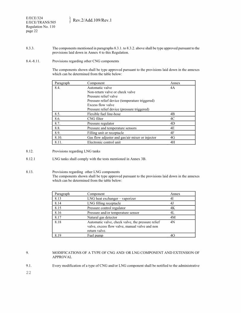
8.3.3. The components mentioned in paragraphs 8.3.1. to 8.3.2. above shall be type approved pursuant to the
provisions laid down in Annex 4 to this Regulation. 8.4.-8.11. Provisions regarding other CNG components
The components shown shall be type approved pursuant to the provisions laid down in the annexes which can be determined from the table below:
Paragraph Component Annex 8.4. Automatic valve
Non-return valve or check valve Pressure relief valve Pressure relief device (temperature triggered) Excess flow valve Pressure relief device (pressure triggered)
4A
8.5. Flexible fuel line-hose 4B 8.6. CNG filter 4C 8.7. Pressure regulator 4D 8.8. Pressure and temperature sensors 4E 8.9. Filling unit or receptacle 4F 8.10. Gas flow adjuster and gas/air mixer or injector 4G 8.11. Electronic control unit 4H
8.12. Provisions regarding LNG tanks 8.12.1 LNG tanks shall comply with the tests mentioned in Annex 3B. 8.13. Provisions regarding other LNG components
The components shown shall be type approved pursuant to the provisions laid down in the annexes which can be determined from the table below:
Paragraph Component Annex 8.13 LNG heat exchanger – vaporizer 4I 8.14 LNG filling receptacle 4J 8.15 Pressure control regulator 4K 8.16 Pressure and/or temperature sensor 4L 8.17 Natural gas detector 4M 8.18 Automatic valve, check valve, the pressure relief
valve, excess flow valve, manual valve and non return valve.
4N
8.19 Fuel pump 4O 9. MODIFICATIONS OF A TYPE OF CNG AND/ OR LNG COMPONENT AND EXTENSION OF
APPROVAL 9.1. Every modification of a type of CNG and/or LNG component shall be notified to the administrative
department which granted the type-approval. The department may then either: 9.1.1. Consider that the modifications made are unlikely to have an appreciable adverse effect, and that the
component still complies with the requirements; or 9.1.2. Determine whether partial or complete retesting has to be established by the competent authority. 9.2. Confirmation or refusal of approval, specifying the alterations, shall be communicated by the
procedure specified in paragraph 7.3. above to the Parties to the Agreement which apply this Regulation.
9.3. The competent authority issuing the extension of approval shall assign a series number to each
communication form drawn up for such an extension. 10. (Not allocated)
11. CONFORMITY OF PRODUCTION
The conformity of production procedures shall comply with those set out in the Agreement, Appendix 2 (E/ECE/324-E/ECE/TRANS/505/Rev.2) with the following requirements:
11.1. Every CNG container shall be tested at a minimum pressure of 1.5 times the working pressure in
conformity with the prescriptions of Annex 3A of this Regulation. Every LNG tank shall be tested at a minimum pressure of 1.3 times (the working pressure plus
0.1MPa) with the prescriptions of Annex 3B of this Regulation. 11.2. For CNG containers burst testing under hydraulic pressure according to paragraph 3.2. of Annex 3A
shall be carried out for each lot consisting of max 200 containers manufactured with the same lot of raw material.
11.3. Every flexible fuel line assembly which is applied in the high and medium pressure (Class 0, 1)
according to the Classification as described in paragraph 3. of this Regulation, shall be tested at the pressure twice the working pressure.
12. PENALTIES FOR NON-CONFORMITY OF PRODUCTION 12.1. The approval granted in respect of a type of component pursuant to this Regulation may be withdrawn
if the requirements laid down in paragraph 11 above are not complied with. 12.2. If a Party to the Agreement applying this Regulation withdraws an approval it has previously granted,
it shall forthwith so notify the other Contracting Parties applying this Regulation, by means of a communication form conforming to the model in Annex 2B to this Regulation.
13. (Not allocated) 14. PRODUCTION DEFINITELY DISCONTINUED If the holder of the approval completely ceases to manufacture a type of component approved in
accordance with this Regulation, he shall so inform the authority which granted the approval. Upon receiving the relevant communication, that authority shall inform thereof the other Parties to the Agreement applying this Regulation by means of a communication form conforming to the model in Annex 2B to this Regulation.
E/ECE/324 E/ECE/TRANS/505 Rev.2/Add.109/Rev.1
Regulation No. 110 page 24
24
15. NAMES AND ADDRESSES OF TECHNICAL SERVICES RESPONSIBLE FOR CONDUCTING APPROVAL TESTS, AND OF ADMINISTRATIVE DEPARTMENTS
The Parties to the Agreement applying this Regulation shall communicate to the United Nations
Secretariat the names and addresses of the Technical Services responsible for conducting approval tests and of the Administrative Departments which grant approval and to which forms certifying approval or extension or refusal or withdrawal of approval, issued in other countries, are to be sent.
PART II
APPROVAL OF VEHICLES WITH REGARD TO THE INSTALLATION OF SPECIFIC COMPONENTS OF AN
APPROVED TYPE FOR THE USE OF COMPRESSED NATURAL GAS (CNG) AND/OR LIQUIFIED NATURAL GAS (LNG) IN THEIR PROPULSION SYSTEM
16 APPLICATION FOR APPROVAL 16.1. The application for approval of a vehicle type with regard to the installation of specific components
for the use of CNG and/or LNG in its propulsion system shall be submitted by the vehicle manufacturer or by his duly accredited representative.
16.2. It shall be accompanied by the under-mentioned documents in triplicate: description of the vehicle
comprising all the relevant particulars referred to in Annex 1B to this Regulation. 16.3. A vehicle representative of the vehicle type to be approved shall be submitted to the Technical Service
conducting the approval tests. 17 APPROVAL 17.1. If the vehicle submitted for approval pursuant to this Regulation is provided with all the necessary
specific components for the use of CNG and/or LNG in its propulsion system and meets the requirements of paragraph 18 below, approval of that vehicle type shall be granted.
17.2. An approval number shall be assigned to each type of vehicle approved. Its first two digits shall
indicate the series of amendments incorporating the most recent major technical amendments made to the Regulation at the time of issue of the approval.
17.3. Notice of approval or of refusal or of extension of approval of a CNG and/or LNG vehicle type
pursuant to this Regulation shall be communicated to the Parties to the Agreement applying this Regulation, by means of a form conforming to the model in Annex 2D to this Regulation.
17.4. There shall be affixed, conspicuously and in a readily accessible space specified on the approval form
referred to in paragraph 17.2. above, to every vehicle type approved under this Regulation an international approval mark consisting of:
17.4.1. A circle surrounding the letter "E" followed by the distinguishing number of the country which has granted approval 2/;
2/ 1 for Germany, 2 for France, 3 for Italy, 4 for the Netherlands, 5 for Sweden, 6 for Belgium, 7 for Hungary, 8 for the Czech Republic, 9 for Spain, 10 for Serbia, 11 for the United Kingdom, 12 for Austria, 13 for Luxembourg, 14 for Switzerland, 15 (vacant), 16 for Norway, 17 for Finland, 18 for Denmark, 19 for Romania, 20 for Poland, 21 for Portugal, 22 for the Russian Federation, 23 for Greece, 24 for Ireland, 25 for Croatia, 26 for Slovenia, 27 for Slovakia, 28 for Belarus, 29 for Estonia, 30 (vacant), 31 for Bosnia and Herzegovina, 32 for Latvia, 33 (vacant), 34 for Bulgaria, 35 (vacant), 36 for Lithuania, 37 for Turkey, 38 (vacant), 39 for Azerbaijan, 40 for The former Yugoslav Republic of Macedonia, 41 (vacant), 42 for the European Community (Approvals are granted by its Member States using their respective ECE symbol), 43 for Japan, 44 (vacant), 45 for Australia, 46 for Ukraine, 47 for South Africa, 48 for New Zealand, 49 for Cyprus, 50 for Malta, 51 for the Republic of Korea, 52 for Malaysia, 53 for Thailand, 54 and 55 (vacant), 56 for Montenegro, 57 (vacant) and 58 for Tunisia. Subsequent numbers shall be assigned to other countries in the chronological order in which they ratify or accede to the Agreement Concerning the Adoption of Uniform Technical Prescriptions for Wheeled Vehicles, Equipment and Parts which can be Fitted and/or be Used on Wheeled Vehicles and
E/ECE/324 E/ECE/TRANS/505 Rev.2/Add.109/Rev.1
Regulation No. 110 page 26
26
17.4.2. The number of this Regulation, followed by the letter "R", a dash and the approval number to the right
of the circle prescribed in paragraph 17.4.1. 17.5. If the vehicle conforms to a vehicle approved, under one or more other Regulations annexed to the
Agreement, in the country that has granted approval under this Regulation, the symbol prescribed in paragraph 17.4.1. need not be repeated; in such case, the Regulation and approval numbers and the additional symbols of all the Regulations under which approval has been granted in the country which has granted approval under this Regulation shall be placed in vertical columns to the right of the symbol prescribed in paragraph 17.4.1.
17.6. The approval mark shall be clearly legible and be indelible. 17.7. The approval mark shall be placed close to or on the vehicle data plate. 17.8. Annex 2C to this Regulation gives examples of the arrangement of the aforesaid approval mark.
the Conditions for Reciprocal Recognition of Approvals Granted on the Basis of these Prescriptions, and the numbers thus assigned shall be communicated by the Secretary-General of the United Nations to the Contracting Parties to the Agreement.
18. REQUIREMENTS FOR THE INSTALLATION OF SPECIFIC COMPONENTS FOR THE USE OF COMPRESSED NATURAL GAS AND/OR LIQUIFIED NATURAL GAS IN THE PROPULSION SYSTEM OF A VEHICLE.
18.1. General 18.1.1. The CNG and/or LNG system of the vehicle shall function in a good and safe manner at the working
pressure and operating temperatures for which it has been designed and approved. 18.1.2. All components of the system shall be type approved as individual parts or multifunctional parts
pursuant to Part I of this Regulation. 18.1.3. The materials used in the system shall be suitable for use with CNG and/or LNG as applicable. 18.1.4. All components of the system shall be fastened in a proper way. 18.1.5. The CNG and/or LNG system shall be pressurized at the working pressure and tested for leakage with
a surface active agent without formation of bubbles for three minutes or by using a demonstrated equivalent method.
18.1.6. The CNG and/or LNG system shall be installed such that is has the best possible protection against
damage, such as damage due to moving vehicle components, collision, grit or due to the loading or unloading of the vehicle or the shifting of those loads.
18.1.7. No appliances shall be connected to the CNG and/or LNG system other than those strictly required for
the proper operation of the engine of the motor vehicle. 18.1.7.1. Notwithstanding the provisions of paragraph 18.1.7., vehicles may be fitted with a heating system heat
the passenger compartment and/or the load area which is connected to the CNG and/or LNG system. 18.1.7.2. The heating system referred to in paragraph 18.1.7.1. shall be permitted if, in the view of the Technical
Services responsible for conducting type-approval, the heating system is adequately protected and the required operation of the normal CNG and/or LNG system is not affected.
18.1.8. Identification of CNG- and/or LNG fuelled vehicles 18.1.8.1. Vehicles of categories M2 and M3 equipped with a CNG system shall be labeled as specified in Annex
6. Vehicles of categories M2 and M3 equipped with a LNG system shall be labeled as specified in Annex
7. 18.1.8.2. The label shall be installed on the front and rear of the vehicle of category M2 or M3 and on the outside
of the doors on the right-hand side.
18.1.8.3. A label shall be placed adjacent to the fill receptacle stating the fuelling requirements. The fuelling requirements shall be as recommended by the manufacturer.
18.2. Further requirements 18.2.1. No component of the CNG and/or LNG system, including any protective materials which form part of
such components, shall project beyond the outline of the vehicle, with the exception of the filling unit

E/ECE/324 E/ECE/TRANS/505 Rev.2/Add.109/Rev.1
Regulation No. 110 page 28
28
if this does not project more than 10 mm beyond its point of attachment. 18.2.2. Proper shielding against heat of adjacent components should be considered and no component of the
CNG and/or LNG system shall be located within 100 mm of the exhaust or similar heat source, unless such components are adequately shielded against heat.
18.3. The CNG and/or LNG system 18.3.1. A CNG system (and the CNG components of the LNG system) shall contain at least the following
components: 18.3.1.1. Container(s) or cylinder(s);1/ 18.3.1.2. Pressure indicator or fuel level indicator;1/ 18.3.1.3. Pressure relief device (temperature triggered);1/ 18.3.1.4. Automatic cylinder valve;1/ 18.3.1.5. Manual valve;1/ 18.3.1.6. Pressure regulator; 18.3.1.7. Gas flow adjuster; 18.3.1.8. Excess flow limiting device;1/ 18.3.1.9. Gas supply device; 18.3.1.10. Filling unit or receptacle;1/ 18.3.1.11. Flexible fuel line; 18.3.1.12. Rigid fuel line; 18.3.1.13. Electronic control unit; 18.3.1.14. Fittings; 18.3.1.15. Gas-tight housing for those components installed inside the luggage and passenger compartment. If
the gas-tight housing will be destroyed in case of fire, the pressure relief device may be covered by the gas-tight housing.
18.3.2. The CNG system (and the CNG components of the LNG system) may also include the following
components: 18.3.2.1. Non-return valve or check valve; 18.3.2.2. Pressure relief valve; 18.3.2.3. CNG filter; 18.3.2.4. Pressure and/or temperature sensor;

18.3.2.5. Fuel selection system and electrical system. 18.3.2.6 PRD (pressure triggered) 18.3.3. An additional automatic valve may be combined with the pressure regulator. 18.3.4 The LNG system shall contain at least the following components: 18.3.4.1 LNG tank(s) or vessel(s); 18.3.4.2. LNG heat exchanger/vaporizer 18.3.4.3. LNG Pressure relief valve 18.3.4.4. LNG venting system 18.3.4.5. LNG receptacle 18.3.4.6. LNG excess flow valve 18.3.4.7. LNG manual valve 18.3.4.8. LNG fuel line 18.3.4.9. LNG couplings 18.3.4.10. LNG check valve or non return valve 18.3.4.11. LNG pressure indicator or fuel indicator 18.3.4.12. Electronic control unit 18.3.5 The LNG system may also include the following components: 18.3.5.1. LNG pressure regulator 18.3.5.2 LNG pressure and/or temperature sensor 18.3.5.3. LNG fuel pump 18.3.5.4. LNG level gauge 18.3.5.5. LNG automatic valve 18.3.5.6. Natural gas detector 18.3.6 LNG vehicles components downstream of (gaseous phase) the heat exchanger/vaporizer shall be
considered as CNG components. A combination of LNG/CNG components shall include at least the components mentioned in 18.3.1.1 – 18.3.1.15 or may consist components mentioned in 18.3.2.1 -18.3.2.6
18.4. Installation of the container and/or tanks. 18.4.1. The container and/or tanks shall be permanently installed in the vehicle and shall not be installed in the
engine compartment. 18.4.2. The container and/or tank shall be installed such that there is no metal to metal contact, with the
exception of the fixing points of the container(s) and/or tank(s). 18.4.3. When the vehicle is ready for use the fuel container and/or tank shall not be less than 200 mm above
the road surface. 18.4.3.1. The provisions of paragraph 18.4.3. shall not apply if the container and/or tank are adequately
protected, at the front and the sides and no part of the container is located lower than this protective structure.
18.4.4. The fuel container(s),and/or tank(s) must be mounted and fixed so that the following accelerations can

E/ECE/324 E/ECE/TRANS/505 Rev.2/Add.109/Rev.1
Regulation No. 110 page 30
30
be absorbed (without damage occurring) when the containers and/or tank(s) are full:
Vehicles of categories M1 and N1: (a) 20 g in the direction of travel (b) 8 g horizontally perpendicular to the direction of travel Vehicles of categories M2 and N2: (a) 10 g in the direction of travel (b) 5 g horizontally perpendicular to the direction of travel Vehicles of categories M3 and N3: (a) 6.6 g in the direction of travel (b) 5 g horizontally perpendicular to the direction of travel A calculation method can be used instead of practical testing if its equivalence can be demonstrated by the applicant for approval to the satisfaction of the Technical Service.
18.5. Accessories fitted to the CNG container(s) 18.5.1. Automatic valve 18.5.1.1. An automatic cylinder valve shall be installed directly on each CNG container. 18.5.1.2. The automatic cylinder valve shall be operated such that the fuel supply is cut off when the engine is
switched off, irrespective of the position of the ignition switch, and shall remain closed while the engine in not running. A delay of 2 seconds is permitted for diagnostic.
18.5.2. Pressure relief device 18.5.2.1. The pressure relief device (temperature triggered) shall be fitted to the CNG fuel container(s) in such a
manner that can discharge into the gas-tight housing if that gas-tight housing fulfils the requirements of paragraph 17.5.5.
18.5.3. Excess flow valve on the CNG container 18.5.3.1. The excess flow limiting device shall be fitted in the CNG fuel container(s) on the automatic cylinder
valve. 18.5.4. Manual valve 18.5.4.1. A manual valve is rigidly fixed to the CNG cylinder which can be integrated into the automatic
cylinder valve. 18.5.5. Gas-tight housing on the CNG container(s) 18.5.5.1. A gas-tight housing over the CNG container(s) fittings, which fulfils the requirements of paragraphs
18.5.5.2. to 18.5.5.5. shall be fitted to the CNG fuel container, unless the CNG container(s) is installed outside the vehicle.
18.5.5.2. The gas-tight housing shall be in open connection with the atmosphere, where necessary through a
connecting hose and a lead-through which shall be resistant against CNG. 18.5.5.3. The ventilation opening of the gas tight housing shall not discharge into a wheel arch, nor shall it be

aimed at a heat source such as the exhaust. 18.5.5.4. Any connecting hose and lead-through in the bottom of the bodywork of the motor vehicle for
ventilation of the gas-tight housing shall have a minimum clear opening of 450 mm2. 18.5.5.5. The housing over the CNG container(s) fittings and connecting hoses shall be gas-tight at a pressure of
10 kPa without any permanent deformations. In these circumstances a leak not exceeding 100 cm3 per hour may be accepted.
18.5.5.6. The connecting hose shall be secured by clamps, or other means, to the gas-tight housing and the lead-
through to ensure that a gas-tight joint is formed. 18.5.5.7. The gas-tight housing shall contain all the components installed into the luggage or passenger
compartment. 18.5.6 PRD (pressure triggered) 18.5.6.1 The PRD (pressure triggered) shall be activated and shall vent the gas independently from the PRD
(temperature triggered). 18.5.6.2 the PRD (pressure triggered) shall be fitted to the fuel container(s) in such a manner that it can
discharge into the gas-tight housing if that gas-tight housing fulfils the requirements of paragraph 18.5.5
18.6 Accessories fitted to the LNG tanks. 18.6.1 Excess flow valve
The excess flow valve can be fitted inside or directly on the LNG tank (in a protected position. Pressure relief valve (primary) The primary pressure relief valve outlet shall be connected to an open ended pipe-away system to move vented gas away to a high level). Consideration shall be given to preventing any blockage or freezing of the pipe-away. The LNG primary relief valve shall not vent into the gas tight housing (if fitted).
18.6.2 Pressure relief valve (primary)
The primary pressure relief valve outlet shall be connected to an open ended pipe-away system to move vented gas away to a high level). Consideration shall be given to preventing any blockage or freezing of the pipe-away. The LNG primary relief valve shall not vent into the gas tight housing (if fitted).
18.6.3 Pressure relief valve (secondary) The secondary relief valve may relieve gas immediately from its outlet. Protection from water ingress and damage should be considered. The secondary relief valve outlet should not be connected to the same pipe-away as the primary relief valve. The LNG secondary relief valve shall not vent into the gas tight housing (if fitted).
18.6.4 Manual Fuel shut off valve The Manual Fuel shut off valve shall be mounted directly on the LNG tank (in a protected position). It should be readily accessible.
18.6.5 Manual Vapour shut off valve The Manual vapour shut off valve shall be mounted directly on the LNG tank (in a protected position) It should be readily accessible.

E/ECE/324 E/ECE/TRANS/505 Rev.2/Add.109/Rev.1
Regulation No. 110 page 32
32
18.6.6 Vent line or connector
The vent line or connector may be mounted inside or on the LNG tank (in a protected position). It should be readily accessible.
18.7. Rigid and flexible fuel lines 18.7.1. CNG rigid fuel lines shall be made of seamless material: either stainless steel or steel with corrosion-resistant
coating. 18.7.1.1 LNG rigid fuel lines shall be made of austenitic stainless steel or copper either seamless or welded. 18.7.2. The CNG rigid fuel line may be replaced by a flexible fuel line if used in Class 0, 1, 2 or 5. 18.7.3. CNG Flexible fuel line shall fulfill the requirement of Annex 4B to this Regulation. 18.7.4. Rigid fuel lines shall be secured such that they shall not be subjected to vibration of stresses. 18.7.5. CNG Flexible fuel lines shall be secured such that they shall not be subjected to vibration or stresses. 18.7.6. At the fixing point, the fuel line, flexible or rigid, shall be fitted in such a way that there is no metal to metal
contact. 18.7.7. Rigid and flexible fuel line shall not be located at jacking points. 18.7.8. At passages the fuel lines shall be fitted with protective material. 18.7.9 LNG fuel lines shall be insulated or protected in those areas where low temperature can damage other
components and/or injure people. 18.8. Fitting or gas connections between the components 18.8.1. Soldered joints and bite-type compression joints are not permitted for CNG. Bite-type compression joints are not
permitted for LNG. 18.8.2. Stainless steel tubes shall only be joined by stainless steel fittings. 18.8.3. Distributing-blocks for CNG shall be made of corrosion-resistant material. 18.8.4. Rigid fuel lines shall be connected by appropriate joints, for example, two-part compression joints in steel tubes
and joints with olives tapered on both sides. 18.8.5. The number of joints shall be limited to a minimum. 18.8.6. Any joints shall be made in locations where access is possible for inspection. 18.8.7. In a passenger compartment or enclosed luggage compartment the fuel lines shall be no longer than reasonably
required, and in any case shall be protected by a gas-tight housing. 18.8.7.1. The provisions of paragraph 18.8.7. shall not apply to vehicles of categories M2 or M3 where the fuel lines and
connections are fitted with a sleeve which is resistant against CNG and which has an open connection to the atmosphere.
18.9. Automatic valve 18.9.1. For CNG system an additional automatic valve may be installed in the fuel line as close as possible
practicable to the pressure regulator. 18.9.2 An automatic valve shall be installed as close as practicable after the vaporizer in the LNG system. 18.10. Filling unit or receptacle 18.10.1. The filling unit shall be secured against rotation and shall be protected against dirt and water. 18.10.2. When the CNG/LNG container or tank is installed in the passenger compartment or a enclosed
(luggage) compartment the filling unit shall be located at the outside of the vehicle or in engine compartment.
18.10.3. For vehicles of classes M1 and N1 the CNG filling unit (receptacle) shall comply with the drawing specifications detailed in Figure 1 of Annex 4F. 1/
18.10.4 For vehicles of categories M2, M3, N2 and N3, the filling unit (receptacle) shall comply with the
drawing specifications detailed in Figure 2 of Annex 4F or with the drawing specifications detailed in Figure 1 of Annex 4F for CNG only.
18.11. Fuel selection system and electrical installation 18.11.1. The electrical components of the CNG /LNG system shall be protected against overloads. 18.11.2 The electrical connections and components in the gas-tight housing shall be constructed such that no
sparks are generated. 18.12 The LNG system shall be designed to prevent any LNG trapping. 19. CONFORMITY OF PRODUCTION 19.1. The conformity of production procedures shall comply with those set out in the Agreement, Appendix
2 (E/ECE/324-E/ECE/TRANS/505/Rev.2). 20. PENALTIES FOR NON-CONFORMITY OF PRODUCTION 20.1. The approval granted in respect of a type of vehicle pursuant to this Regulation may be withdrawn if
the requirements referred to in paragraph 18 above are not complied with. 20.2. If a Party to the Agreement applying this Regulation withdraws an approval it has previously granted,
it shall forthwith so notify the other Contracting Parties applying this Regulation, by means of a communication form conforming to the model in Annex 2D to this Regulation.
21. MODIFICATION AND EXTENSION OF APPROVAL OF A VEHICLE TYPE 21.1. Every modification of the installation of the specific components for the use of compressed natural gas
and/or liquefied natural gas in the propulsion system of the vehicle shall be notified to the administrative department which approved the vehicle type. The department may then either:
_________________________
1/ As defined in Annex 7 to the Consolidated Resolution on the Construction of Vehicles (R.E.3) (document TRANS/WP.29/78/Rev.1/Amend.2 as last amended by Amend.4).

E/ECE/324 E/ECE/TRANS/505 Rev.2/Add.109/Rev.1
Regulation No. 110 page 34
34
21.1.1. Consider that the modifications made are unlikely to have an appreciably adverse effect and that in any case the
vehicle still complies with the requirements; or
21.1.2. Require a further test report from the Technical Service responsible for conducting the tests. 21.2. Confirmation or refusal of approval, specifying the alteration, shall be communicated to the Parties to the
Agreement applying this Regulation by means of a form conforming to the model in Annex 2D to this Regulation. 21.3. The competent authority issuing the extension of approval shall assign a series number for such an extension and
inform thereof the other Parties to the 1958 Agreement applying this Regulation by means of a communication form conforming to the model in Annex 2D to this Regulation.
22. PRODUCTION DEFINITELY DISCONTINUED If the holder of the approval completely ceases to manufacture a type of vehicle approved in accordance with this
Regulation, he shall so inform the authority which granted the approval. Upon receiving the relevant communication, that authority shall inform thereof the other Parties to the Agreement applying this Regulation by means of a communication form conforming to the model in Annex 2D to this Regulation.
23. NAMES AND ADDRESSES OF TECHNICAL SERVICES RESPONSIBLE FOR CONDUCTING APPROVAL
TESTS, AND OF ADMINISTRATIVE DEPARTMENTS The Parties to the Agreement applying this Regulation shall communicate to the United Nations Secretariat the
names and addresses of the Technical Services responsible for conducting approval tests and of the Administrative Departments which grant approval and to which forms certifying approval or extension or refusal or withdrawal of approval, issued in other countries, are to be sent.
Annex 1A
ESSENTIAL CHARACTERISTICS OF THE CNG/LNG COMPONENT 1. (Not allocated) 1.2.4.5.1. System description: 1.2.4.5.2. CNG Pressure regulator(s): yes/no 1/ 1.2.4.5.2.1. Make(s): .............................................................................................................................................. 1.2.4.5.2.2. Type(s): ............................................................................................................................................... 1.2.4.5.2.5. Drawings: ............................................................................................................................................ 1.2.4.5.2.6. Number of main adjustment points ..................................................................................................... 1.2.4.5.2.7. Description of principle of adjustment through main adjustment points: ............................................ 1.2.4.5.2.8. Number of idle adjustment points: ...................................................................................................... 1.2.4.5.2.9. Description of principles of adjustment through idle adjustment points: ............................................ 1.2.4.5.2.10. Other adjustment possibilities: if so and which (description and drawings): 1.2.4.5.2.11. Working pressure(s): 2/ ................................................................................................................. kPa 1.2.4.5.2.12. Material: .............................................................................................................................................. 1.2.4.5.2.13. Operating temperatures: 2/ ............................................................................................................. C 1.2.4.5.3. CNG Gas/air mixer: yes/no 1/ 1.2.4.5.3.1. Number: .............................................................................................................................................. 1.2.4.5.3.2. Make(s): .............................................................................................................................................. 1.2.4.5.3.3. Type(s): ............................................................................................................................................... 1.2.4.5.3.4. Drawings: ............................................................................................................................................ 1.2.4.5.3.5. Adjustment possibilities: ..................................................................................................................... 1.2.4.5.3.6. Working pressure(s): 2/ ................................................................................................................. kPa 1.2.4.5.3.7. Material: .............................................................................................................................................. 1.2.4.5.3.8. Operating temperatures: 2/ ............................................................................................................. C 1.2.4.5.4. CNG Gas flow adjuster: yes/no 1/ 1.2.4.5.4.1. Number: ..............................................................................................................................................

36
1.2.4.5.4.2. Make(s): .............................................................................................................................................. 1.2.4.5.4.3. Type(s): ............................................................................................................................................... 1.2.4.5.4.4. Drawings: ............................................................................................................................................ 1.2.4.5.4.5. Adjustment possibilities (description) 1.2.4.5.4.6 Working pressure(s): 2/ ................................................................................................................. kPa 1.2.4.5.4.7. Material: .............................................................................................................................................. 1.2.4.5.4.8. Operating temperatures: 2/ ............................................................................................................. C 1.2.4.5.5. CNG Gas injector(s): yes/no 1/ 1.2.4.5.5.1. Make(s): .............................................................................................................................................. 1.2.4.5.5.2. Type(s): ............................................................................................................................................... 1.2.4.5.5.3. Identification: ...................................................................................................................................... 1.2.4.5.5.4. Working pressure(s): 2/ ................................................................................................................. kPa 1.2.4.5.5.5. Drawings of installation: ..................................................................................................................... 1.2.4.5.5.6. Material: .............................................................................................................................................. 1.2.4.5.5.7. Operating temperatures: 2/ ............................................................................................................. C 1.2.4.5.6. Electronic Control Unit yes/no 1/ 1.2.4.5.6.1. Make(s): .............................................................................................................................................. 1.2.4.5.6.2. Type(s): ............................................................................................................................................... 1.2.4.5.6.3. Adjustment possibilities: ..................................................................................................................... 1.2.4.5.6.4. Basic software principles: ................................................................................................................... 1.2.4.5.6.5. Operating temperatures: 2/ ............................................................................................................. C 1.2.4.5.7. CNG container(s) or cylinder(s): yes/no 1/ ........................................................................................ LNG tank(s) or vessel(s): yes/no 1/ ..................................................................................................... 1.2.4.5.7.1. Make(s): .............................................................................................................................................. 1.2.4.5.7.2. Type(s) (include drawings): ................................................................................................................ 1.2.4.5.7.3. Capacity: ..................................................................................................................................... liters 1.2.4.5.7.4. Drawings of the installation of the container/tank2/:...........................................................................
1.2.4.5.7.5. Dimensions: .........................................................................................................................................
1.2.4.5.7.6. Material: .............................................................................................................................................. 1.2.4.5.8. CNG container/LNG tank accessories 1.2.4.5.8.1. Pressure indicator: yes/no 1/ 1.2.4.5.8.1.1. Make(s): .............................................................................................................................................. 1.2.4.5.8.1.2. Type(s): ............................................................................................................................................... 1.2.4.5.8.1.3. Operating principle: float/other 1/ (include description or drawings) ............................................................................................................................................. 1.2.4.5.8.1.4. Working pressure(s): 2/ ................................................................................................................ MPa 1.2.4.5.8.1.5. Material: .............................................................................................................................................. 1.2.4.5.3.1.6. Operating temperatures: 2/ ............................................................................................................. C 1.2.4.5.8.2. Pressure relief valve (discharge valve): yes/no 1/ 1.2.4.5.8.2.1. Make(s): .............................................................................................................................................. 1.2.4.5.8.2.2. Type(s): ............................................................................................................................................... 1.2.4.5.8.2.3. Working pressure(s) 2/: ................................................................................................................ MPa 1.2.4.5.8.2.4. Material: .............................................................................................................................................. 1.2.4.5.8.2.5. Operating temperatures: 2/ ............................................................................................................. C 1.2.4.5.8.3. Automatic cylinder valve 1.2.4.5.8.3.1. Make(s): .............................................................................................................................................. 1.2.4.5.8.3.2. Type(s): ............................................................................................................................................... 1.2.4.5.8.3.3. Working pressure(s) 2/: ................................................................................................................ MPa 1.2.4.5.8.3.4. Material: .............................................................................................................................................. 1.2.4.5.8.3.5. Operating temperatures: 2/ ............................................................................................................. C 1.2.4.5.8.4. Excess flow valve: yes/no 1/ 1.2.4.5.8.4.1. Make(s): .............................................................................................................................................. 1.2.4.5.8.4.2. Type(s): ............................................................................................................................................... 1.2.4.5.8.4.3. Working pressure(s) 2/: ................................................................................................................ MPa 1.2.4.5.8.4.4. Material: ..............................................................................................................................................

38
1.2.4.5.8.4.5. Operating temperatures: 2/ ............................................................................................................. C 1.2.4.5.8.5. Gas-tight housing: yes/no 1/ 1.2.4.5.8.5.1. Make(s): .............................................................................................................................................. 1.2.4.5.8.5.2. Type(s): ............................................................................................................................................... 1.2.4.5.8.5.3. Working pressure(s) 2/: ................................................................................................................ MPa 1.2.4.5.8.5.4. Material: .............................................................................................................................................. 1.2.4.5.8.5.5. Operating temperatures: 2/ ............................................................................................................. C 1.2.4.5.8.6. Manual valve: yes/no 1/ 1.2.4.5.8.6.1. Make(s): .............................................................................................................................................. 1.2.4.5.8.6.2. Type(s): ............................................................................................................................................... 1.2.4.5.8.6.3. Drawings: ............................................................................................................................................ 1.2.4.5.8.6.4. Working pressure(s) 2/: ................................................................................................................ MPa 1.2.4.5.8.6.5. Material: .............................................................................................................................................. 1.2.4.5.8.6.6. Operating temperatures: 2/ ............................................................................................................. C 1.2.4.5.8.7. Heat Exchanger /Vaporizer: yes/no 1/ ................................................................................................. 1.2.4.5.8.7.1. Make(s): .............................................................................................................................................. 1.2.4.5.8.7.2. Type(s): ............................................................................................................................................... 1.2.4.5.8.7.3. Drawings: ............................................................................................................................................ 1.2.4.5.8.7.4. Working pressure(s) 2/: ................................................................................................................ MPa 1.2.4.5.8.7.5. Material: .............................................................................................................................................. 1.2.4.5.8.7.6. Operating temperatures: 2/ ............................................................................................................. C 1.2.4.5.8.8. Natural gas detector: yes/no 1/ 1.2.4.5.8.8.1. Make(s): .............................................................................................................................................. 1.2.4.5.8.8.2. Type(s): ............................................................................................................................................... 1.2.4.5.8.8.3. Drawings: ............................................................................................................................................ 1.2.4.5.8.8.4. Working pressure(s) 2/: ................................................................................................................ MPa 1.2.4.5.8.8.5. Material: ..............................................................................................................................................

1.2.4.5.8.8.6. Operating temperatures: 2/ ............................................................................................................. C 1.2.4.5.8.8.7. Set Values ........................................................................................................................................... 1.2.4.5.9. Pressure relief device (temperature triggered): yes/no 1/ 1.2.4.5.9.1. Make(s): .............................................................................................................................................. 1.2.4.5.9.2. Type(s): ............................................................................................................................................... 1.2.4.5.9.3. Description and drawings: ................................................................................................................... 1.2.4.5.9.4. Activation temperature: 2/ ............................................................................................................... C 1.2.4.5.9.5. Material: .............................................................................................................................................. 1.2.4.5.9.6. Operating temperatures: 2/ ............................................................................................................. C 1.2.4.5.10. Filling unit or receptacle: yes/no 1/ 1.2.4.5.10.1. Make(s): .............................................................................................................................................. 1.2.4.5.10.2. Type(s): ............................................................................................................................................... 1.2.4.5.10.3. Working pressure(s) 2/: ................................................................................................................ MPa 1.2.4.5.10.4. Description and drawings: ................................................................................................................... 1.2.4.5.10.5. Material: .............................................................................................................................................. 1.2.4.5.10.6. Operating temperatures: 2/ ............................................................................................................. C 1.2.4.5.11. Flexible fuel lines: yes/no 1/ 1.2.4.5.11.1. Make(s): .............................................................................................................................................. 1.2.4.5.11.2. Type(s): ............................................................................................................................................... 1.2.4.5.11.3. Description: ......................................................................................................................................... 1.2.4.5.11.4. Working pressure(s): 2/ ................................................................................................................. kPa 1.2.4.5.11.5. Material: .............................................................................................................................................. 1.2.4.5.11.6. Operating temperatures: 2/ ............................................................................................................. C 1.2.4.5.12. Pressure and Temperature sensor(s): yes/no 1/ 1.2.4.5.12.1. Make(s): .............................................................................................................................................. 1.2.4.5.12.2. Type(s): ............................................................................................................................................... 1.2.4.5.12.3. Description: .........................................................................................................................................
40
1.2.4.5.12.4. Working pressure(s): 2/ ................................................................................................................. kPa 1.2.4.5.12.5. Material: .............................................................................................................................................. 1.2.4.5.12.6. Operating temperatures: 2/ ............................................................................................................. C 1.2.4.5.13. Filter(s): yes/no 1/ 1.2.4.5.13.1. Make(s): .............................................................................................................................................. 1.2.4.5.13.2. Type(s): ............................................................................................................................................... 1.2.4.5.13.3. Description: ......................................................................................................................................... 1.2.4.5.13.4. Working pressure(s): 2/ ................................................................................................................. kPa 1.2.4.5.13.5. Material: .............................................................................................................................................. 1.2.4.5.13.6. Operating temperatures: 2/ ............................................................................................................. C 1.2.4.5.14. Non-return valve(s) or check valve(s): yes/no 1/ 1.2.4.5.14.1. Make(s): .............................................................................................................................................. 1.2.4.5.14.2. Type(s): ............................................................................................................................................... 1.2.4.5.14.3. Description: ......................................................................................................................................... 1.2.4.5.14.4. Working pressure(s): 2/ ................................................................................................................. kPa 1.2.4.5.14.5. Material: .............................................................................................................................................. 1.2.4.5.14.6. Operating temperatures: 2/ ............................................................................................................. C 1.2.4.5.15. Connection to CNG/LNG system for heating system: yes/no 1/ 1.2.4.5.15.1. Make(s): .............................................................................................................................................. 1.2.4.5.15.2. Type(s): ............................................................................................................................................... 1.2.4.5.15.3. Description and drawings of installation: ............................................................................................ 1.2.4.5.16. PRD (pressure triggered): yes/no 1/ 1.2.4.5.16.1. Make(s): ............................................................................................................................................. 1.2.4.5.16.2. Type(s): .............................................................................................................................................. 1.2.4.5.16.3. Description and drawings: ............................................................................................................. 1.2.4.5.16.4. Activation pressure: 2/ ............................................................................................................ MPa 1.2.4.5.16.5. Material: ........................................................................................................................................

1.2.4.5.16.6. Operating temperatures: 2/ ...................................................................................................... °C" 1.2.4.5.17 LNG filling receptacle(s): yes/no 1/ 1.2.4.5.17.1. Make(s):......................................................................................................................................... 1.2.4.5.17.2. Type(s): ......................................................................................................................................... 1.2.4.5.17.3. Description: ................................................................................................................................... 1.2.4.5.17.4. Working pressure(s): 2/ ........................................................................................................... kPa 1.2.4.5.17.5. Material: ........................................................................................................................................ 1.2.4.5.18. LNG pressure control regulator(s): yes/no 1/ 1.2.4.5.18.1. Make(s):......................................................................................................................................... 1.2.4.5.18.2. Type(s): ......................................................................................................................................... 1.2.4.5.18.3. Description: ................................................................................................................................... 1.2.4.5.18.4. Working pressure(s): 2/ ........................................................................................................... kPa 1.2.4.5.18.5. Material: ........................................................................................................................................ 1.2.4.5.19. Pressure and/or temperature sensor(s): yes/no 1/ 1.2.4.5.19.1. Make(s):......................................................................................................................................... 1.2.4.5.19.2. Type(s): ......................................................................................................................................... 1.2.4.5.19.3. Description: ................................................................................................................................... 1.2.4.5.19.4. Working pressure(s): 2/ ........................................................................................................... kPa 1.2.4.5.19.5. Material: ........................................................................................................................................ 1.2.4.5.20. LNG manual valve(s): yes/no 1/ 1.2.4.5.20.1. Make(s):......................................................................................................................................... 1.2.4.5.20.2. Type(s): ......................................................................................................................................... 1.2.4.5.20.3. Description: ................................................................................................................................... 1.2.4.5.20.4. Working pressure(s): 2/ ........................................................................................................... kPa 1.2.4.5.20.5. Material: ........................................................................................................................................ 1.2.4.5.21. LNG Automatic valve(s): yes/no 1/ 1.2.4.5.21.1. Make(s):.........................................................................................................................................
42
1.2.4.5.21.2. Type(s): ......................................................................................................................................... 1.2.4.5.21.3. Description: ................................................................................................................................... 1.2.4.5.21.4. Working pressure(s): 2/ ........................................................................................................... kPa 1.2.4.5.21.5. Material: ........................................................................................................................................ 1.2.4.5.22. LNG non return valve(s): yes/no 1/ 1.2.4.5.22.1. Make(s): ......................................................................................................................................... 1.2.4.5.22.2. Type(s): ......................................................................................................................................... 1.2.4.5.22.3. Description: ................................................................................................................................... 1.2.4.5.22.4. Working pressure(s): 2/ ........................................................................................................... kPa 1.2.4.5.22.5. Material: ........................................................................................................................................ 1.2.4.5.23. LNG pressure relief valve(s): yes/no 1/ 1.2.4.5.23.1. Make(s): ......................................................................................................................................... 1.2.4.5.23.2. Type(s): ......................................................................................................................................... 1.2.4.5.23.3. Description: ................................................................................................................................... 1.2.4.5.23.4. Working pressure(s): 2/ ........................................................................................................... kPa 1.2.4.5.23.5. Material: ........................................................................................................................................ 1.2.4.5.24. LNG excess flow valve(s): yes/no 1/ 1.2.4.5.24.1. Make(s): ......................................................................................................................................... 1.2.4.5.24.2. Type(s): ......................................................................................................................................... 1.2.4.5.24.3. Description: ................................................................................................................................... 1.2.4.5.24.4. Working pressure(s): 2/ ........................................................................................................... kPa 1.2.4.5.24.5. Material: ........................................................................................................................................ 1.2.4.5.25. LNG fuel pump(s): yes/no 1/ 1.2.4.5.25.1. Make(s): .........................................................................................................................................
1.2.4.5.25.2. Type(s): .........................................................................................................................................
1.2.4.5.25.3. Description: ................................................................................................................................... 1.2.4.5.25.4. Working pressure(s): 2/ ........................................................................................................... kPa

1.2.4.5.25.5. Location inside/outside LNG tank 1/: ............................................................................................ 1.2.4.5.25.6. Operating temperatures: 2/ ....................................................................................................... C 1.2.5. Cooling system: (liquid/air) 1/ 1.2.5.1. System description/drawings with regard to the CNG/LNG system: ............................................................................................................................................................ ______________________
1/ Strike out what does not apply.
2/ Specify the tolerance.

44
Annex 1B
ESSENTIAL CHARACTERISTICS OF THE VEHICLE, ENGINE AND CNG/LNG -RELATED SYSTEM
0. DESCRIPTION OF THE VEHICLE(S) 0.1. Make: .................................................................................................................................................. 0.2. Type(s): ............................................................................................................................................... 0.3. Name and address of the manufacturer: .............................................................................................. 0.4. Engine type(s) and approval No.(Nos.): .............................................................................................. 1. DESCRIPTION OF THE ENGINE(S) 1.1. Manufacturer: ...................................................................................................................................... 1.1.1. Manufacturer's engine code(s) (as marked on the engine or other means of identification): ............. 1.2. Internal combustion engine 1.2.3. (Not allocated) 1.2.4.5.1. (Not allocated) 1.2.4.5.2. Pressure regulator(s): 1.2.4.5.2.1. Make(s): .............................................................................................................................................. 1.2.4.5.2.2. Type(s): ............................................................................................................................................... 1.2.4.5.2.3. Working pressure(s): 2/ ................................................................................................................. kPa 1.2.4.5.2.4. Material: .............................................................................................................................................. 1.2.4.5.2.5. Operating temperatures: 2/ ............................................................................................................. C 1.2.4.5.3. Gas/air mixer: yes/no 1/ 1.2.4.5.3.1. Number: .............................................................................................................................................. 1.2.4.5.3.2. Make(s): .............................................................................................................................................. 1.2.4.5.3.3. Type(s): ............................................................................................................................................... 1.2.4.5.3.4. Working pressure(s): 2/ ................................................................................................................. kPa 1.2.4.5.3.5. Material: .............................................................................................................................................. 1.2.4.5.3.6. Operating temperatures: 2/ ............................................................................................................. C 1.2.4.5.4. Gas flow adjuster: yes/no 1/

1.2.4.5.4.1. Number: ............................................................................................................................................... 1.2.4.5.4.2. Make(s): .............................................................................................................................................. 1.2.4.5.4.3. Type(s): ............................................................................................................................................... 1.2.4.5.4.4. Working pressure(s): 2/ ................................................................................................................. kPa 1.2.4.5.4.5. Material: .............................................................................................................................................. 1.2.4.5.4.6. Operating temperatures: 2/ ............................................................................................................. C 1.2.4.5.5. Gas injector(s): yes/no 1/ 1.2.4.5.5.1. Make(s): .............................................................................................................................................. 1.2.4.5.5.2. Type(s): ............................................................................................................................................... 1.2.4.5.5.3. Working pressure(s): 2/ ................................................................................................................. kPa 1.2.4.5.5.4. Material: .............................................................................................................................................. 1.2.4.5.5.5. Operating temperatures: 2/ ............................................................................................................. C 1.2.4.5.6. Electronic Control Unit yes/no 1/ 1.2.4.5.6.1. Make(s): .............................................................................................................................................. 1.2.4.5.6.2. Type(s): ............................................................................................................................................... 1.2.4.5.6.3. Basic software principles: ................................................................................................................... 1.2.4.5.6.4. Operating temperatures: 2/ ............................................................................................................. C 1.2.4.5.7. CNG container(s) or cylinder(s): yes/no 1/ ........................................................................................ LNG tank(s) or vessel(s): yes/no 1/ ..................................................................................................... 1.2.4.5.7.1. Make(s): .............................................................................................................................................. 1.2.4.5.7.2. Type(s): ............................................................................................................................................... 1.2.4.5.7.3. Capacity: ..................................................................................................................................... liters 1.2.4.5.7.4. Approval number: ................................................................................................................................ 1.2.4.5.7.5. Dimensions: ......................................................................................................................................... 1.2.4.5.7.6. Material: .............................................................................................................................................. 1.2.4.5.8. CNG container/LNG tank accessories: 1.2.4.5.8.1. Pressure indicator:

46
1.2.4.5.8.1.1. Make(s) ............................................................................................................................................... 1.2.4.5.8.1.2. Type(s): ............................................................................................................................................... 1.2.4.5.8.1.3. Working pressure(s) 2/: ................................................................................................................ MPa 1.2.4.5.8.1.4. Material: .............................................................................................................................................. 1.2.4.5.8.1.5. Operating temperatures: 2/ ............................................................................................................. C 1.2.4.5.8.2. Pressure relief valve (discharge valve): yes/no 1/ 1.2.4.5.8.2.1 Make(s): .............................................................................................................................................. 1.2.4.5.8.2.2 Type(s): ............................................................................................................................................... 1.2.4.5.8.2.3 Working pressure 2/: .................................................................................................................... MPa 1.2.4.5.8.2.4. Material: .............................................................................................................................................. 1.2.4.5.8.2.5. Operating temperatures: 2/ ............................................................................................................. C 1.2.4.5.8.3. Automatic valve(s): 1.2.4.5.8.3.1. Make(s): .............................................................................................................................................. 1.2.4.5.8.3.2. Type(s): ............................................................................................................................................... 1.2.4.5.8.3.3. Working pressure(s) 2/: ................................................................................................................ MPa 1.2.4.5.8.3.4. Material: .............................................................................................................................................. 1.2.4.5.8.3.5. Operating temperatures: 2/ ............................................................................................................. C 1.2.4.5.8.4. Excess flow valve: yes/no 1/ 1.2.4.5.8.4.1. Make(s): .............................................................................................................................................. 1.2.4.5.8.4.2. Type(s): ............................................................................................................................................... 1.2.4.5.8.4.3. Working pressure(s) 2/: ................................................................................................................ MPa 1.2.4.5.8.4.4. Material: .............................................................................................................................................. 1.2.4.5.8.4.5. Operating temperatures: 2/ ............................................................................................................. C 1.2.4.5.8.5. Gas-tight housing: yes/no 1/ 1.2.4.5.8.5.1 Make(s): .............................................................................................................................................. 1.2.4.5.8.5.2 Type(s): ............................................................................................................................................... 1.2.4.5.8.5.3. Working pressure(s) 2/: ................................................................................................................ MPa

1.2.4.5.8.5.4. Material: .............................................................................................................................................. 1.2.4.5.8.5.5. Operating temperatures: 2/ ............................................................................................................. C 1.2.4.5.8.6. Manual valve: 1.2.4.5.8.6.1 Make(s): .............................................................................................................................................. 1.2.4.5.8.6.2 Type(s): ............................................................................................................................................... 1.2.4.5.8.6.3 Working pressure(s) 2/: ............................................................................................................... MPa 1.2.4.5.8.6.4. Material: .............................................................................................................................................. 1.2.4.5.8.6.5. Operating temperatures: 2/ ............................................................................................................. C 1.2.4.5.8.7. Heat Exchanger /Vaporizer: yes/no 1/ ................................................................................................. 1.2.4.5.8.7.1. Make(s): .............................................................................................................................................. 1.2.4.5.8.7.2. Type(s): ............................................................................................................................................... 1.2.4.5.8.7.3. Working pressure(s) 2/: ............................................................................................................... MPa 1.2.4.5.8.7.4. Material: .............................................................................................................................................. 1.2.4.5.8.7.5. Operating temperatures: 2/ ............................................................................................................. C 1.2.4.5.8.8. Natural gas detector: yes/no 1/ 1.2.4.5.8.8.1. Make(s): .............................................................................................................................................. 1.2.4.5.8.8.2. Type(s): ............................................................................................................................................... 1.2.4.5.8.8.3. Working pressure(s) 2/: ............................................................................................................... MPa 1.2.4.5.8.8.4. Material: .............................................................................................................................................. 1.2.4.5.8.8.5. Operating temperatures: 2/ ............................................................................................................. C 1.2.4.5.8.8.6. Set Values ............................................................................................................................................ 1.2.4.5.9. Pressure relief device (temperature triggered): yes/no 1/ 1.2.4.5.9.1. Make(s): .............................................................................................................................................. 1.2.4.5.9.2. Type(s): ............................................................................................................................................... 1.2.4.5.9.3. Activation temperature: 2/ ............................................................................................................... C 1.2.4.5.9.4. Material: .............................................................................................................................................. 1.2.4.5.9.5. Operating temperatures: 2/ ............................................................................................................. C

48
1.2.4.5.10. Filling unit or receptacle: yes/no 1/ 1.2.4.5.10.1. Make(s): .............................................................................................................................................. 1.2.4.5.10.2. Type(s): ............................................................................................................................................... 1.2.4.5.10.3. Working pressure(s) 2/: ................................................................................................................ MPa 1.2.4.5.10.4. Material: .............................................................................................................................................. 1.2.4.5.10.5. Operating temperatures: 2/ ............................................................................................................. C 1.2.4.5.11. Flexible fuel lines: yes/no 1/ 1.2.4.5.11.1. Make(s): .............................................................................................................................................. 1.2.4.5.11.2. Type(s): ............................................................................................................................................... 1.2.4.5.11.3. Working pressure(s): 2/ ................................................................................................................. kPa 1.2.4.5.11.4. Material: .............................................................................................................................................. 1.2.4.5.11.5. Operating temperatures: 2/ ............................................................................................................. C 1.2.4.5.12. Pressure and temperature sensor(s): yes/no 1/ 1.2.4.5.12.1. Make(s): .............................................................................................................................................. 1.2.4.5.12.2. Type(s): ............................................................................................................................................... 1.2.4.5.12.3. Working pressure(s): 2/ ................................................................................................................. kPa 1.2.4.5.12.4. Material: .............................................................................................................................................. 1.2.4.5.12.5. Operating temperatures: 2/ ............................................................................................................. C 1.2.4.5.13. Filter: yes/no 1/ 1.2.4.5.13.1. Make(s): .............................................................................................................................................. 1.2.4.5.13.2. Type(s): ............................................................................................................................................... 1.2.4.5.13.3. Working pressure(s): 2/ ................................................................................................................. kPa 1.2.4.5.13.4. Material: .............................................................................................................................................. 1.2.4.5.13.5. Operating temperatures: 2/ ............................................................................................................. C 1.2.4.5.14. Non-return valve(s) or check valve(s): yes/no 1 1.2.4.5.14.1. Make(s): .............................................................................................................................................. 1.2.4.5.14.2. Type(s): ...............................................................................................................................................

1.2.4.5.14.3. Working pressure(s): 2/ ................................................................................................................. kPa 1.2.4.5.14.4. Material: .............................................................................................................................................. 1.2.4.5.14.5. Operating temperatures: 2/ ............................................................................................................. C 1.2.4.5.15. Connection to CNG/LNG /2 system for heating system: yes/no 1/ 1.2.4.5.15.1. Make(s): .............................................................................................................................................. 1.2.4.5.15.2. Type(s): ............................................................................................................................................... 1.2.4.5.15.3. Description and drawings of installation: ............................................................................................ 1.2.4.5.16. PRD (pressure triggered): yes/no 1/ 1.2.4.5.16.1. Make(s): ............................................................................................................................................. 1.2.4.5.16.2. Type(s): .............................................................................................................................................. 1.2.4.5.16.3. Activation pressure: 2/ .................................................................................................................. Mpa 1.2.4.5.16.4. Material: .............................................................................................................................................. 1.2.4.5.16.5. Operating temperatures: 2/ ............................................................................................................ °C" 1.2.4.5.17. LNG manual valve(s): yes/no 1/ 1.2.4.5.17.1. Make(s): .............................................................................................................................................. 1.2.4.5.17.2. Type(s): ............................................................................................................................................... 1.2.4.5.17.3. Description: ......................................................................................................................................... 1.2.4.5.17.4. Working pressure(s): 2/ ................................................................................................................. kPa 1.2.4.5.17.5. Material: ..............................................................................................................................................
1.2.4.5.18. LNG Automatic valve(s): yes/no 1/ 1.2.4.5.18.1. Make(s): .............................................................................................................................................. 1.2.4.5.18.2. Type(s): ............................................................................................................................................... 1.2.4.5.18.3. Description: ......................................................................................................................................... 1.2.4.5.18.4. Working pressure(s): 2/ ................................................................................................................. kPa
1.2.4.5.18.5. Material: ..............................................................................................................................................
1.2.4.5.19. LNG non return valve(s): yes/no 1/ 1.2.4.5.19.1. Make(s): ....................................................................................................................................................

50
1.2.4.5.19.2. Type(s): ..................................................................................................................................................... 1.2.4.5.19.3. Description: ............................................................................................................................................... 1.2.4.5.19.4. Working pressure(s): 2/ ....................................................................................................................... kPa 1.2.4.5.19.5. Material: .................................................................................................................................................... 1.2.4.5.20. LNG pressure relief valve(s): yes/no 1/ 1.2.4.5.20.1. Make(s): .................................................................................................................................................... 1.2.4.5.20.2. Type(s): ..................................................................................................................................................... 1.2.4.5.20.3. Description: ............................................................................................................................................... 1.2.4.5.20.4. Working pressure(s): 2/ ....................................................................................................................... kPa 1.2.4.5.20.5. Material: ....................................................................................................................................................
1.2.4.5.21. LNG excess flow valve(s): yes/no 1/ 1.2.4.5.21.1. Make(s): .................................................................................................................................................... 1.2.4.5.21.2. Type(s): ..................................................................................................................................................... 1.2.4.5.21.3. Description: ............................................................................................................................................... 1.2.4.5.21.4. Working pressure(s): 2/ ....................................................................................................................... kPa 1.2.4.5.21.5. Material: .................................................................................................................................................... 1.2.4.5.22. LNG fuel pump(s): yes/no 1/ 1.2.4.5.22.1. Make(s): .................................................................................................................................................... 1.2.4.5.22.2. Type(s): ..................................................................................................................................................... 1.2.4.5.22.3. Description: ............................................................................................................................................... 1.2.4.5.22.4. Working pressure(s): 2/ ....................................................................................................................... kPa 1.2.4.5.22.5. Location inside/outside LNG tank 1/: ....................................................................................................... 1.2.4.5.25.6. Operating temperatures: 2/ ................................................................................................................... C 1.2.4.5.26. Further documentation: .............................................................................................................................
1.2.4.5.26.1. Description of the CNG/LNG system 1.2.4.5.26.2. System lay-out (electrical connections, vacuum connections compensation hoses, etc.): 1.2.4.5.26.3. Drawing of the symbol:
1.2.4.5.26.4. Adjustment data: ............................................................................................................................ 1.2.4.5.26.5. Certificate of the vehicle on petrol, if already granted: 1.2.5. Cooling system: (liquid/air) 1/ ______________________
1/ Strike out what does not apply.
2/ Specify the tolerance.
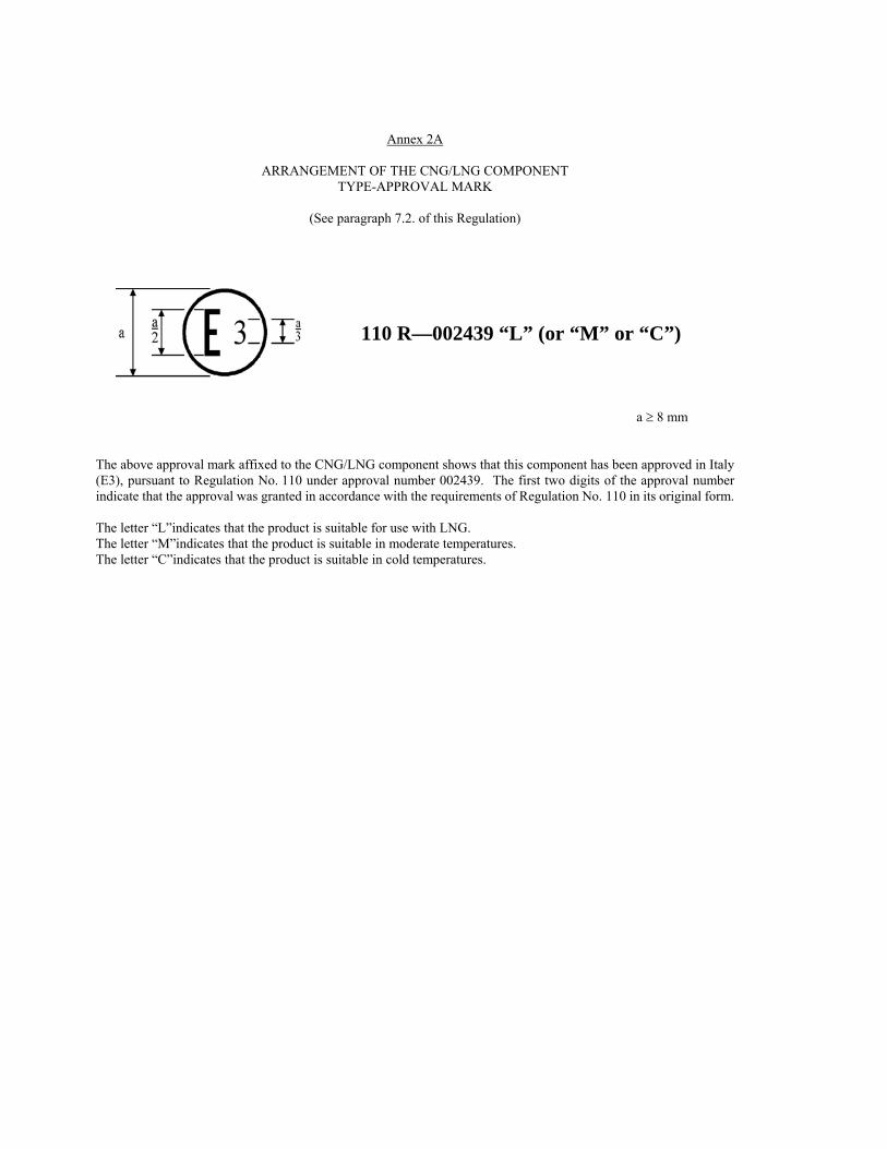
Annex 2A
ARRANGEMENT OF THE CNG/LNG COMPONENT TYPE-APPROVAL MARK
(See paragraph 7.2. of this Regulation)
110 R—002439 “L” (or “M” or “C”)
a 8 mm The above approval mark affixed to the CNG/LNG component shows that this component has been approved in Italy (E3), pursuant to Regulation No. 110 under approval number 002439. The first two digits of the approval number indicate that the approval was granted in accordance with the requirements of Regulation No. 110 in its original form. The letter “L”indicates that the product is suitable for use with LNG. The letter “M”indicates that the product is suitable in moderate temperatures. The letter “C”indicates that the product is suitable in cold temperatures.

Annex 2B
COMMUNICATION
(Maximum format: A4 (210 x 297 mm))
concerning: 2/ APPROVAL GRANTED
APPROVAL EXTENDED APPROVAL REFUSED APPROVAL WITHDRAWN PRODUCTION DEFINITELY DISCONTINUED
Of a type of CNG/LNG component pursuant to Regulation No. 110 Approval No.: .................... Extension No.: ................. 1. CNG/LNG component considered:
Container(s) or cylinder(s) 2/ Tank(s) or vessel(s) 2/ Pressure indicator 2/ Pressure relief valve 2/ Automatic valve(s) 2/ Excess flow valve 2/ Gas-tight housing 2/ Pressure regulator(s) 2/ Non-return valve(s) 2/ or check valve(s) 2/ Pressure relief device (PRD) (temperature triggered) 2/ Manual valve 2/ CNG Flexible fuel lines 2/ Filling unit or receptacle 2/ Gas injector(s) 2/ Gas flow adjuster 2/ Gas/air mixer 2/ Electronic control unit 2/ Pressure and temperature sensor(s) 2/ Natural gas detector(s) 2/ CNG filter(s) 2/ PRD (pressure triggered) 2/ LNG Heat exchanger -Vaporizer 2/ LNG filling receptacle 2/ LNG pressure control regulator 2/ LNG pressure and/or temperature sensor 2/ LNG natural gas detector 2/ LNG manual valve 2/ LNG automatic valve 2/ LNG non return valve 2/
LNG pressure relief valve 2/
issued by : Name of administration: ...................................... ...................................... ......................................

54
LNG excess flow valve2/ LNG fuel pump inside tank 2/
2. Trade name or mark: ............................................................................................................................................ 3. Manufacturer's name and address: ....................................................................................................................... 4. If applicable, name and address of manufacturer's representative: ....................................................................... ............................................................................................................................................................................. 5. Submitted for approval on: ................................................................................................................................... 6. Technical Service responsible for conducting approval tests: .............................................................................. ............................................................................................................................................................................. 7. Date of report issued by that service: ................................................................................................................... 8. No. of report issued by that service: ..................................................................................................................... 9. Approval granted/refused/extended/withdrawn 2/ 10. Reason(s) of extension (if applicable): ................................................................................................................. 11. Place: .................................................................................................................................................................... 12. Date: ..................................................................................................................................................................... 13. Signature: ............................................................................................................................................................. 14. The documents filed with the application or extension of approval can be obtained upon request. ______________________
1/ distinguishing number of the country that has granted/extended/refused/withdrawn approval (see approval provisions in the Regulation).
2/ Strike out what does not apply.
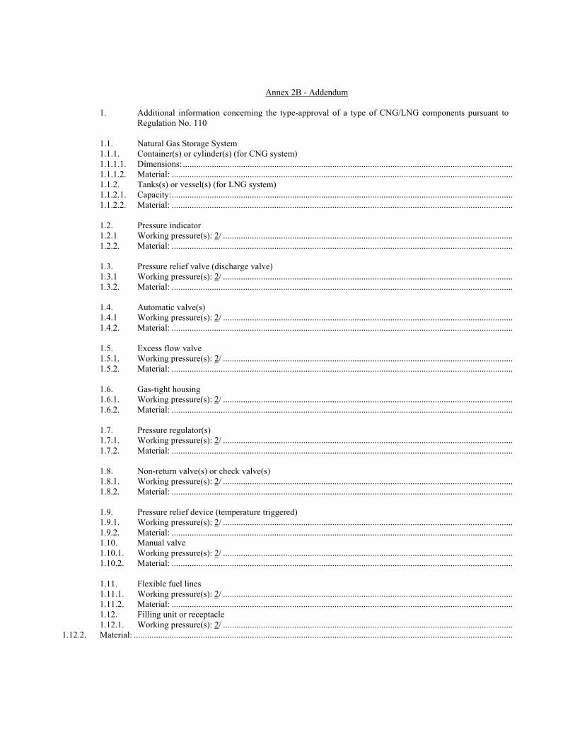
Annex 2B - Addendum 1. Additional information concerning the type-approval of a type of CNG/LNG components pursuant to
Regulation No. 110 1.1. Natural Gas Storage System 1.1.1. Container(s) or cylinder(s) (for CNG system) 1.1.1.1. Dimensions: .................................................................................................................................................... 1.1.1.2. Material: ......................................................................................................................................................... 1.1.2. Tanks(s) or vessel(s) (for LNG system) 1.1.2.1. Capacity: ......................................................................................................................................................... 1.1.2.2. Material: ......................................................................................................................................................... 1.2. Pressure indicator 1.2.1 Working pressure(s): 2/ .................................................................................................................................. 1.2.2. Material: ......................................................................................................................................................... 1.3. Pressure relief valve (discharge valve) 1.3.1 Working pressure(s): 2/ .................................................................................................................................. 1.3.2. Material: ......................................................................................................................................................... 1.4. Automatic valve(s) 1.4.1 Working pressure(s): 2/ .................................................................................................................................. 1.4.2. Material: ......................................................................................................................................................... 1.5. Excess flow valve 1.5.1. Working pressure(s): 2/ .................................................................................................................................. 1.5.2. Material: ......................................................................................................................................................... 1.6. Gas-tight housing 1.6.1. Working pressure(s): 2/ .................................................................................................................................. 1.6.2. Material: ......................................................................................................................................................... 1.7. Pressure regulator(s) 1.7.1. Working pressure(s): 2/ .................................................................................................................................. 1.7.2. Material: ......................................................................................................................................................... 1.8. Non-return valve(s) or check valve(s) 1.8.1. Working pressure(s): 2/ .................................................................................................................................. 1.8.2. Material: ......................................................................................................................................................... 1.9. Pressure relief device (temperature triggered) 1.9.1. Working pressure(s): 2/ .................................................................................................................................. 1.9.2. Material: ......................................................................................................................................................... 1.10. Manual valve 1.10.1. Working pressure(s): 2/ .................................................................................................................................. 1.10.2. Material: ......................................................................................................................................................... 1.11. Flexible fuel lines 1.11.1. Working pressure(s): 2/ .................................................................................................................................. 1.11.2. Material: ......................................................................................................................................................... 1.12. Filling unit or receptacle 1.12.1. Working pressure(s): 2/ ..................................................................................................................................
1.12.2. Material: ..........................................................................................................................................................................

56
1.13. Gas injector(s) 1.13.1. Working pressure(s): 2/ ................................................................................................................................................... 1.13.2. Material: .......................................................................................................................................................................... 1.14. Gas flow adjuster 1.14.1. Working pressure(s): 2/ ................................................................................................................................................... 1.14.2. Material: .......................................................................................................................................................................... 1.15. Gas/air mixer 1.15.1. Working pressure(s): 2/ ................................................................................................................................................... 1.15.2. Material: .......................................................................................................................................................................... 1.16. Electronic control unit 1.16.1. Basic software principles:................................................................................................................................................ 1.17. Pressure and temperature sensor(s) 1.17.1. Working pressure(s): 2/ ................................................................................................................................................... 1.17.2. Material: .......................................................................................................................................................................... 1.18. CNG filter(s) 1.18.1. Working pressure(s): 2/ ................................................................................................................................................... 1.18.2. Material: .......................................................................................................................................................................... 1.19. PRD (pressure triggered) 1.19.1. Working pressure(s): 2/ ............................................................................................................................................MPa 1.19.2. Material: ........................................................................................................................................................................ " 1.20. LNG Vaporizer(s) 1.20.1. Working pressure(s): 2/ ............................................................................................................................................. kPa 1.20.2. Material: .......................................................................................................................................................................... 1.21. LNG filling receptacle(s): yes/no 1/ 1.21.1. Working pressure(s): 2/ ............................................................................................................................................. kPa 1.21.2. Material: .......................................................................................................................................................................... 1.22 LNG pressure control regulator(s): yes/no 1/ 1.22.1. Working pressure(s): 2/ ............................................................................................................................................. kPa 1.22.2 Material: ...........................................................................................................................................................................
1.23 LNG pressure and/or temperature sensor 1/ 1.23.1. Working pressure(s): 2/ ............................................................................................................................................. kPa 1.23.2 Material: ..........................................................................................................................................................................
1.24. Natural Gas Detector(s) 1.24.1. Working pressure(s): 2/ ............................................................................................................................................. kPa 1.24.2. Material: .......................................................................................................................................................................... 1.25 LNG Manual valve(s)
1.25.1 Working pressure(s): 2/………………………………………………………………………………...kPa 1.25.2 Material: 1.26 LNG Automatic valve(s) 2/ 1.26.1 Working pressure(s)………………………………………………………………………………….…kPa
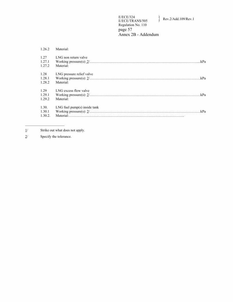
E/ECE/324E/ECE/TRANS/505 Rev.2/Add.109/Rev.1
Regulation No. 110 page 57 Annex 2B - Addendum
1.26.2 Material: 1.27 LNG non return valve 1.27.1 Working pressure(s): 2/………………………………………………………………………………....kPa 1.27.2 Material: 1.28 LNG pressure relief valve 1.28.1 Working pressure(s): 2/…………………………………………………………………………………kPa 1.28.2 Material: 1.29 LNG excess flow valve 1.29.1 Working pressure(s): 2/…………………………………………………………………………………kPa 1.29.2 Material: 1.30. LNG fuel pump(s) inside tank 1.30.1 Working pressure(s): 2/…………………………………………………………………………………kPa 1.30.2. Material:…………………………………………………………………………………….
______________________
1/ Strike out what does not apply.
2/ Specify the tolerance.

Annex 2C
ARRANGEMENT OF APPROVAL MARKS
Model A (See paragraph 17.2. of this Regulation)
110 R—002439 “L” (or “M” or “C”)
a 8 mm The above approval mark affixed to a vehicle shows that the vehicle has, with regard to the installation of CNG/LNG system for the use of natural gas for propulsion, been approved in Italy (E3), pursuant to Regulation No. 110 under approval number 002439. The first two digits of the approval number indicate that the approval was granted in accordance with the requirements of Regulation No. 110 in its original form. The letter “L” indicates that the product is suitable for use with LNG. The letter “M” indicates that the product is suitable in moderate temperatures. The letter “C” indicates that the product is suitable in cold temperatures.
Model B (See paragraph 17.2. of this Regulation)
110 002439 “L” (or “M” or “C”) 83 041628
a 8 mm The above approval mark affixed to a vehicle shows that the vehicle has, with regard to the installation of CNG/LNG system for the use of natural gas for propulsion, been approved in Italy(E3), pursuant to Regulation No. 110 under approval number 002439. The first two digits of the approval number indicate that at the date the approval was granted in accordance with the requirements of Regulation No. 110 in its original form and that Regulation No. 83 included the 04 series of amendments.
The letter “L” indicates that the product is suitable for use with LNG. The letter “M” indicates that the product is suitable in moderate temperatures. The letter “C” indicates that the product is suitable in cold temperatures.

Annex 2D
COMMUNICATION
(Maximum format: A4 (210 x 297 mm))
Concerning: 2/ APPROVAL GRANTED
APPROVAL EXTENDED APPROVAL REFUSED APPROVAL WITHDRAWN PRODUCTION DEFINITELY DISCONTINUED
Of a vehicle type with regard to the installation of CNG/LNG system pursuant to Regulation No. 110 Approval No.: .................... Extension No.: ................. 1. Trade name or mark of vehicle: ...................................................................................................................... 2. Vehicle type: ................................................................................................................................................... 3. Vehicle category: ............................................................................................................................................ 4. Manufacturer's name and address: .................................................................................................................. 5. If applicable, name and address of manufacturer's representative: ................................................................. ........................................................................................................................................................................ 6. Description of the vehicle, drawings, etc. (needs detailing): .......................................................................... ........................................................................................................................................................................ 7. Test results: ..................................................................................................................................................... 8. Vehicle submitted for approval on: ................................................................................................................. 9. Technical Service responsible for conducting approval tests: ........................................................................ 10. Date of report issued by that service: .............................................................................................................. 11. CNG/LNG system 11.1. Trade name or mark of components and their approval numbers: .................................................................. 11.1.1. Container(s) or cylinder(s): ............................................................................................................................. 11.1.2. Tanks(s) or vessel(s): ......................................................................................................................................
issued by : Name of administration: ...................................... ...................................... ......................................

E/ECE/324 E/ECE/TRANS/505 Rev.2/Add.109/Rev.1
Regulation No. 110 page 60 Annex 2D
60
11.1.3. etc. (see para. 2.2. of the Regulation) ............................................................................................................. 12. No. of report issued by that service: ............................................................................................................... 13. Approval granted/refused/extended/withdrawn 2/ .......................................................................................... 14. Reason(s) of extension (if applicable): ........................................................................................................... 15. Place: .............................................................................................................................................................. 16. Date: ............................................................................................................................................................... 17. Signature:........................................................................................................................................................ 18. The following documents filed with the application or extension of approval can be obtained upon request:
Drawings, diagrams and scheme plans regarding the components and the installation of the CNG/LNG equipment considered to be of importance for the purpose of this Regulation; Where applicable drawings of the various equipment and their position in the vehicle.
______________________
1/ Distinguishing number of the country that has granted/extended/refused/withdrawn approval (see approval provisions in the Regulation.)
2/ Strike out what does not apply.
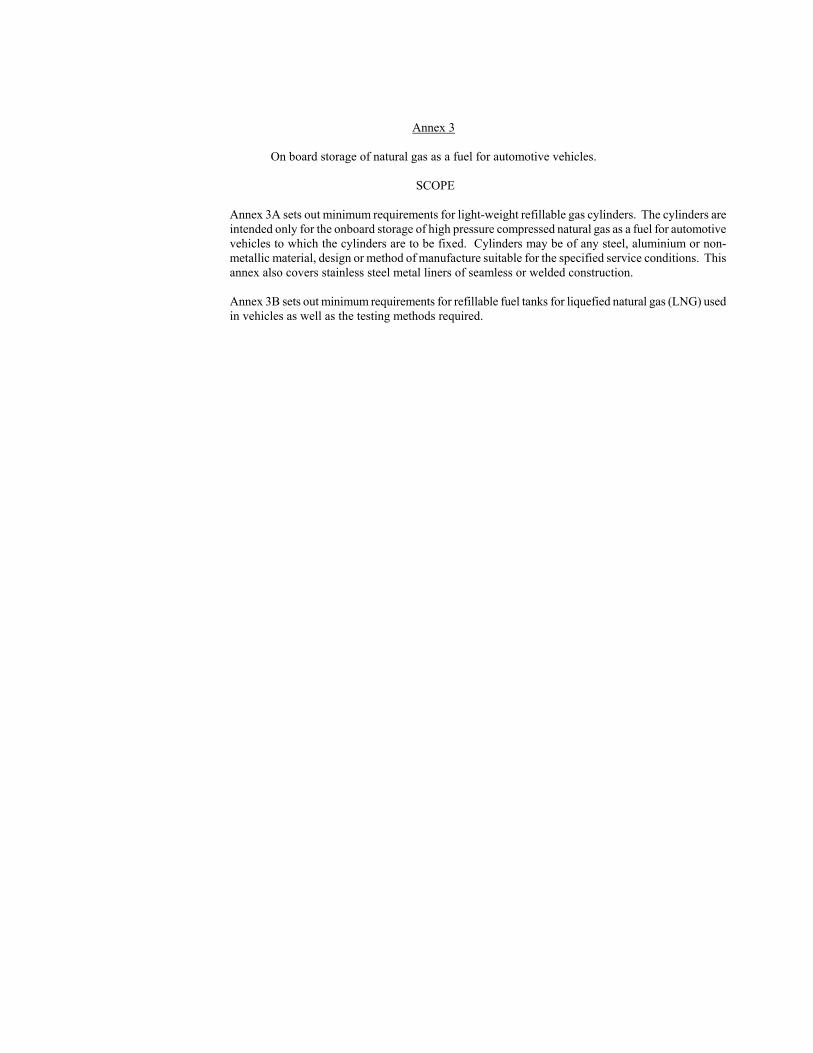
Annex 3
On board storage of natural gas as a fuel for automotive vehicles.
SCOPE
Annex 3A sets out minimum requirements for light-weight refillable gas cylinders. The cylinders are intended only for the onboard storage of high pressure compressed natural gas as a fuel for automotive vehicles to which the cylinders are to be fixed. Cylinders may be of any steel, aluminium or non-metallic material, design or method of manufacture suitable for the specified service conditions. This annex also covers stainless steel metal liners of seamless or welded construction. Annex 3B sets out minimum requirements for refillable fuel tanks for liquefied natural gas (LNG) used in vehicles as well as the testing methods required.
62
Annex 3A
Gas cylinders - High pressure cylinder for the on-board storage of CNG compressed natural gas as a fuel for automotive vehicles
1 SCOPE Cylinders covered by this annex are classified in Class 0, as described in paragraph 3. of this
Regulation, and are: CNG-1 Metal CNG-2 Metal liner reinforced with resin impregnated continuous filament (hoop wrapped) CNG-3 Metal liner reinforced with resin impregnated continuous filament (fully wrapped) CNG-4 Resin impregnated continuous filament with a non-metallic liner (all composite) Service conditions to which the cylinders will be subjected are detailed in paragraph 4. This annex is based upon a working pressure for natural gas as a fuel of 20 MPa settled at 15 C with a maximum filling pressure of 26 MPa. Other working pressures can be accommodated by adjusting the pressure by the appropriate factor (ratio). For example, a 25 MPa working pressure system will require pressures to be multiplied by 1.25. The service life of the cylinder shall be defined by the manufacturer and may vary with applications. Definition of service life is based upon filling the cylinders 1,000 times a year for a minimum of 15,000 fills. The maximum service life shall be 20 years. For metal and metal-lined cylinders, the cylinder life is based upon the rate of fatigue crack growth. The ultrasonic inspection, or equivalent, of each cylinder or liner is required to ensure the absence of flaws which exceed the maximum allowable size. This approach permits the optimized design and manufacture of light weight cylinders for natural gas vehicle service. For all-composite cylinders with non-metallic non-load bearing liners the "safe life" is demonstrated by appropriate design methods, design qualification testing and manufacturing controls.
2 REFERENCES (see page 6) 3 DEFINITIONS (see page 12)
4. SERVICE CONDITIONS 4.1. General 4.1.1. Standard service conditions The standard service conditions specified in this section are provided as a basis for the design,
manufacture, inspection, testing, and approval of cylinders that are to be mounted permanently on vehicles and used to store natural gas at ambient temperatures for use as a fuel on vehicles.
4.1.2. Use of cylinders The service conditions specified are also intended to provide information on how cylinders made to
this Regulation may safely be used to:

(a) manufacturers of cylinders; (b) owners of cylinders; (c) designers or contractors responsible for the installation of cylinders; (d) designers or owners of equipment used to refuel vehicle cylinders; (e) suppliers of natural gas; and (f) regulatory authorities who have jurisdiction over cylinder use.
4.1.3. Service life The service life for which cylinders are safe shall be specified by the cylinder designer on the basis of
use under service conditions specified herein. The maximum service life shall be 20 years. 4.1.4. Periodic requalification Recommendations for periodic requalification by visual inspection or testing during the service life
shall be provided by the cylinder manufacturer on the basis of use under service conditions specified herein. Each cylinder shall be visually inspected at least every 48 months after the date of its entry into service on the vehicle (vehicle registration), and at the time of any re-installation, for external damage and deterioration, including under the support straps. The visual inspection shall be performed by a competent agency approved or recognized by the Regulatory Authority, in accordance with the manufacturers specifications: Cylinders without label containing mandatory information, or with labels containing mandatory information that are illegible in any way shall be removed from service. If the cylinder can be positively identified by manufacturer and serial number, a replacement label may be applied, allowing the cylinder to remain in service.
4.1.4.1. Cylinders involved in collisions Cylinders which have been involved in a vehicle collision shall be reinspected by an agency authorized
by the manufacturer, unless otherwise directed by the Authority having jurisdiction. Cylinders that have not experienced any impact damage from the collision may be returned to service, otherwise the cylinder shall be returned to the manufacturer for evaluation.
4.1.4.2 Cylinders involved in fires Cylinders which have been subject to the action of fire shall be reinspected by an agency authorized by
the manufacturer, or condemned and removed from service. 4.2. Maximum pressures The cylinder pressure shall be limited to the following:
(a) a pressure that would settle to 20 MPa at a settled temperature of 15 C; (b) 26 MPa, immediately after filling, regardless of temperature;
4.3. Maximum number of filling cycles Cylinders are designed to be filled up to a settled pressure of 20 MPa bar at a settled gas temperature
of 15 C for up to 1,000 times per year of service. 4.4. Temperature range 4.4.1. Settled gas temperature
64
Settled temperature of gas in cylinders may vary from a minimum of -40 C to a maximum of 65 C; 4.4.2. Cylinder temperatures The temperature of the cylinder materials may vary from a minimum of -40 C to a maximum of +82
C; Temperatures over +65 C may be sufficiently local, or of short enough duration, that the temperature
of gas in the cylinder never exceeds +65 C, except under the conditions of paragraph 4.4.3; 4.4.3. Transient temperatures
Developed gas temperatures during filling and discharge may vary beyond the limits of paragraph 4.4.1;
4.5. Gas composition Methanol and/or glycol shall not be deliberately added to the natural gas. Cylinder should be designed
to tolerate being filled with natural gas meeting either of the following three conditions:
(a) SAE J1616 (b) Dry gas Water vapour would normally be limited to less than 32 mg/m3. a pressure dew point of -9 C at 20
MPa. There would be no constituent limits for dry gas, except for: Hydrogen sulfide and other soluble sulfides: 23 mg/m3 Oxygen: 1 percent by volume Hydrogen shall be limited to 2 percent by volume when cylinders are manufactured from a steel with
an ultimate tensile strength exceeding 950 MPa; (c) Wet gas Gas that contains water content higher than b) normally meets the following constituent limits; Hydrogen sulfide and other soluble sulfides: 23 mg/m3 Oxygen: 1 percent by volume Carbon dioxide: 4 percent by volume Hydrogen: 0.1 percent by volume Under wet gas conditions, a minimum of 1 mg of compressor oil per kg of gas is necessary to protect
metallic cylinders and liners. 4.6. External surfaces Cylinders are not designed for continuous exposure to mechanical or chemical attack, e.g. leakage
from cargo that may be carried on vehicles or severe abrasion damage from road conditions, and shall comply with recognized installation standards. However, cylinder external surfaces may be inadvertently exposed to:

(a) water, either by intermittent immersion or road spray; (b) salt, due to the operation of the vehicle near the ocean or where ice-melting salt is used; (c) ultra-violet radiation from sunlight; (d) impact of gravel; (e) solvents, acids and alkalis, fertilizers; and (f) automotive fluids, including gasoline, hydraulic fluids, glycol and oils.
4.7. Gas permeation or leakage
Cylinders may be located in enclosed spaces for extended periods of time. Permeation of gas through the cylinder wall or leakage between the end connections and the liner shall be considered in the design.
5. DESIGN APPROVAL 5.1. General
The following information shall be submitted by the cylinder designer with a request for approval to the Competent Authority:
(a) statement of service (paragraph 5.2.) (b) design data (paragraph 5.3.) (c) manufacturing data (paragraph 5.4.) (d) quality system (paragraph 5.5.) (e) fracture performance and NDE (Non Destructive Examination) defect size (paragraph 5.6.); (f) specification sheet (paragraph 5.7.) (g) additional supporting data (paragraph 5.8.) For cylinders designed in accordance with ISO 9809 it is not required to provide the stress
analysis report in paragraph 5.3.2. or the information in paragraph 5.6. 5.2. Statement of service
The purpose of this statement of service is to guide users and installers of cylinders as well as to inform the approving Competent Authority, or their designated representative. The statement of service shall include: (a) a statement that the cylinder design is suitable for use in the service conditions defined in
paragraph 4 for the service life of the cylinder; (b) the service life; (c) the minimum in-service test and/or inspection requirements; (d) the pressure relief devices and/or insulation required; (e) support methods, protective coatings, etc., required but not provided; (f) a description of the cylinder design; (g) any other information necessary to ensure the safe use and inspection of the cylinder.

66
5.3. Design data 5.3.1. Drawings Drawings shall show the following as a minimum:
(a) Title, reference number, date of issue, and revision numbers with dates of issue if applicable; (b) Reference to this Regulation and the cylinder type; (c) All dimensions complete with tolerances, including details of end closure shapes with
minimum thicknesses and of openings; (d) Mass, complete with tolerance, of cylinders; (e) Material specifications complete with minimum mechanical and chemical properties or
tolerance ranges and, for metal cylinders or metal liners, the specified hardness range; (f) Other data such as, auto-frettage pressure range, minimum test pressure, details of the fire
protection system and of the exterior protective coating. 5.3.2. Stress analysis report A finite element stress analysis or other stress analysis shall be provided; A table summarizing the calculated stresses in the report shall be provided. 5.3.3. Material test data A detailed description of the materials and tolerances of the materials properties used in the design
shall be provided. Test data shall also be presented characterizing the mechanical properties and the suitability of the materials for service under the conditions specified in paragraph 4.
5.3.4. Design qualification test data The cylinder material, design, manufacture and examination shall be provided to be adequate for their
intended service by meeting the requirements of the tests required for the particular cylinder design, when tested in accordance with the relevant methods of test detailed in Appendix A to this annex.
The test data shall also document the dimensions, wall thicknesses and weights of each of the test cylinders.
5.3.5. Fire protection The arrangement of pressure relief devices that will protect the cylinder from sudden rupture when
exposed to the fire conditions in paragraph A.15 shall be specified. Test data shall substantiate the effectiveness of the specified fire protection system.
5.3.6. Cylinder supports Details of cylinder supports or support requirements shall be provided in accordance with paragraph
6.11. 5.4. Manufacturing data Details of all fabrication processes, non-destructive examinations, production tests and batch tests
Shall be provided; The tolerances for all production processes such as heat treatment, end forming, resin mix ratio, filament winding tension and speed, curing times and temperatures, and auto-frettage procedures shall be specified; Surface finish, thread details, acceptance criteria for ultrasonic scanning (or equivalent), and maximum lot sizes for batch tests shall also be specified.

5.5. (not allocated) 5.6. Fracture performance and NDE defect size 5.6.1. Fracture performance The manufacturer shall demonstrate the Leak-Before-Break performance of the design as described in
paragraph 6.7. 5.6.2. NDE defect size Using the approach described in paragraph 6.15.2 the manufacturer shall establish the maximum defect
size for non-destructive examination which will prevent the failure of the cylinder during its service life due to fatigue, or failure of the cylinder by rupture.
5.7. Specification sheet A summary of the documents providing the information required in paragraph 5.1. shall be listed on a
specification sheet for each cylinder design. The title, reference number, revision numbers and dates of original issue and version issues of each document shall be given. All documents shall be signed or initialed by the issuer; The specification sheet shall be given a number, and revision numbers if applicable, that can be used to designate the cylinder design and shall carry the signature of the engineer responsible for the design. Space shall be provided on the specification sheet for a stamp indicating registration of the design.
5.8. Additional supporting data Additional data which would support the application, such as the service history of material proposed
for use, or the use of a particular cylinder design in other service conditions, shall be provided where applicable.
5.9. Approval and certification 5.9.1. Inspection and testing Evaluation of conformity is required to be performed in accordance with the provisions of paragraph 9
of this Regulation; In order to ensure that the cylinders are in compliance with this international Regulation they shall be
subject to inspection in accordance with paragraphs 6.13. and 6.14. performed by the Competent Authority.
5.9.2. Test certificate If the results of prototype testing according to paragraph 6.13. are satisfactory, the Competent
Authority shall issue a test certificate. An example of a test certificate is given in Appendix D to this annex.
5.9.3. Batch acceptance certificate The Competent Authority shall prepare an acceptance certificate as provided in Appendix D to this
annex.
68
6. REQUIREMENTS APPLICABLE TO ALL CYLINDER TYPES 6.1. General The following requirements are generally applicable to the cylinder types specified in paragraphs 7 to
10. The design of cylinders shall cover all relevant aspects which are necessary to ensure that every cylinder produced according to the design is fit for its purpose for the specified service life; Type CNG-1 steel cylinders designed in accordance with ISO 9809 and meeting all the requirements therein are only required to meet the requirements of paragraphs 6.3.2.4. and 6.9 to 6.13.
6.2. Design This Regulation does not provide design formulas nor permissible stresses or strains, but requires the
adequacy of the design to be established by appropriate calculations and demonstrated by cylinders being capable of consistently passing the materials, design qualification, production and batch tests specified in this Regulation; All designs shall ensure a "leakage before break" failure mode under feasible degradation of pressure parts during normal service. If leakage of metal cylinders or metal liners occurs, it shall be only by the growth of a fatigue crack.
6.3. Materials 6.3.1. Materials used shall be suitable for the service conditions specified in paragraph 4. The design shall
not have incompatible materials in contact. The design qualification tests for materials are summarized in table 6.1.
6.3.2. Steel 6.3.2.1. Composition Steels shall be aluminum and/or silicon killed and produced to predominantly fine grain practice. The
chemical composition of all steels shall be declared and defined at least by:
(a) carbon, manganese, aluminum and silicon contents in all cases; (b) nickel, chromium, molybdenum, boron and vanadium contents, and any other alloying elements
intentionally added. The following limits shall not be exceeded in the cast analysis:
Tensile strength < 950 Mpa 950 MPa Sulfur 0.020 percent 0.010 percent Phosphorus 0.020 percent 0.020 percent Sulfur and Phosphorus 0.030 percent 0.025 percent
When carbon-boron steel is used, a hardenability test in accordance with ISO 642, shall be performed on the first and last ingot or slab of each heat of steel. The hardness as measured in a distance of 7.9 mm from the quenched end, shall be within the range 33-53 HRC, or 327-560 HV, and shall be certified by the material manufacturer;
6.3.2.2. Tensile properties The mechanical properties of the steel in the finished cylinder or liner shall be determined in
accordance with paragraph A.1 (Appendix A). The elongation for steel shall be at least 14 percent; 6.3.2.3. Impact properties
The impact properties of the steel in the finished cylinder or liner shall be determined in accordance
with paragraph A.2 (Appendix A). Impact values shall not be less than that indicated in table 6.2 of this annex;
6.3.2.4. Bending properties The bending properties of the welded stainless steel in the finished liner shall be determined in
accordance with paragraph A.3. (Appendix A). 6.3.2.5. Macroscopic weld examination A macroscopic weld examination for each type of welding procedure shall be performed. It shall show
complete fusion and shall be free of any assembly faults or unacceptable defects as specified according to level C in EN ISO 5817.
6.3.2.6. Sulfide stress cracking resistance If the upper limit of the specified tensile strength for the steel exceeds 950 MPa, the steel from a
finished cylinder shall be subjected to a sulphide stress cracking resistance test in accordance with Appendix A to this annex, item A.3. and meet the requirements listed therein.
6.3.3. Aluminum 6.3.3.1. Composition Aluminum alloys shall be quoted in line with Aluminum Association practice for a given alloy system.
The impurity limits for lead and bismuth in any aluminum alloy shall not exceed 0.003 percent; 6.3.3.2. Corrosion tests Aluminum alloys shall meet the requirements of the corrosion tests carried out in accordance with
paragraph A.4 (Appendix A); 6.3.3.3. Sustained load cracking Aluminum alloys shall meet the requirements of the sustained load cracking tests carried out in
accordance with paragraph A.5 (Appendix A); 6.3.3.4. Tensile properties The mechanical properties of the aluminum alloy in the finished cylinder shall be determined in
accordance with paragraph A.l (Appendix A). The elongation for aluminum shall be at least 12 percent.
6.3.4. Resins 6.3.4.1. General The material for impregnation may be thermosetting or thermoplastic resins. Examples of suitable
matrix materials are epoxy, modified epoxy, polyester and vinyl ester thermosetting plastics, and polyethylene and polyamide thermoplastic material;
6.3.4.2. Shear strength
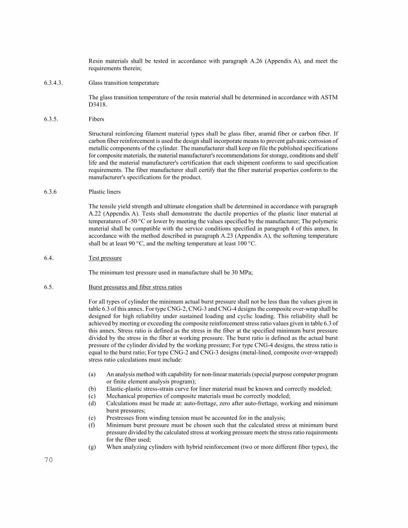
70
Resin materials shall be tested in accordance with paragraph A.26 (Appendix A), and meet the requirements therein;
6.3.4.3. Glass transition temperature The glass transition temperature of the resin material shall be determined in accordance with ASTM
D3418. 6.3.5. Fibers Structural reinforcing filament material types shall be glass fiber, aramid fiber or carbon fiber. If
carbon fiber reinforcement is used the design shall incorporate means to prevent galvanic corrosion of metallic components of the cylinder. The manufacturer shall keep on file the published specifications for composite materials, the material manufacturer's recommendations for storage, conditions and shelf life and the material manufacturer's certification that each shipment conforms to said specification requirements. The fiber manufacturer shall certify that the fiber material properties conform to the manufacturer's specifications for the product.
6.3.6 Plastic liners The tensile yield strength and ultimate elongation shall be determined in accordance with paragraph
A.22 (Appendix A). Tests shall demonstrate the ductile properties of the plastic liner material at temperatures of -50 C or lower by meeting the values specified by the manufacturer; The polymeric material shall be compatible with the service conditions specified in paragraph 4 of this annex. In accordance with the method described in paragraph A.23 (Appendix A), the softening temperature shall be at least 90 C, and the melting temperature at least 100 C.
6.4. Test pressure The minimum test pressure used in manufacture shall be 30 MPa; 6.5. Burst pressures and fiber stress ratios For all types of cylinder the minimum actual burst pressure shall not be less than the values given in
table 6.3 of this annex. For type CNG-2, CNG-3 and CNG-4 designs the composite over-wrap shall be designed for high reliability under sustained loading and cyclic loading. This reliability shall be achieved by meeting or exceeding the composite reinforcement stress ratio values given in table 6.3 of this annex. Stress ratio is defined as the stress in the fiber at the specified minimum burst pressure divided by the stress in the fiber at working pressure. The burst ratio is defined as the actual burst pressure of the cylinder divided by the working pressure; For type CNG-4 designs, the stress ratio is equal to the burst ratio; For type CNG-2 and CNG-3 designs (metal-lined, composite over-wrapped) stress ratio calculations must include:
(a) An analysis method with capability for non-linear materials (special purpose computer program
or finite element analysis program); (b) Elastic-plastic stress-strain curve for liner material must be known and correctly modeled; (c) Mechanical properties of composite materials must be correctly modeled; (d) Calculations must be made at: auto-frettage, zero after auto-frettage, working and minimum
burst pressures; (e) Prestresses from winding tension must be accounted for in the analysis; (f) Minimum burst pressure must be chosen such that the calculated stress at minimum burst
pressure divided by the calculated stress at working pressure meets the stress ratio requirements for the fiber used;
(g) When analyzing cylinders with hybrid reinforcement (two or more different fiber types), the

load share between the different fibers must be considered based on the different elastic modulii of the fibers. The stress ratio requirements for each individual fiber type must be in accordance with the values given in table 6.3. of this annex. Verification of the stress ratios may also be performed using strain gauges. An acceptable method is outlined in the informative Appendix E to this annex.
6.6. Stress analysis A stress analysis shall be performed to justify the minimum design wall thicknesses. It shall include
the determination of the stresses in liners and fibers of composite designs. 6.7. Leak-before-break (LBB) assessment Types CNG-1, CNG-2 and CNG-3 cylinders shall demonstrate Leak-Before-Break (LBB)
performance. The LBB performance test shall be carried out in accordance with paragraph A.6 (Appendix A). Demonstration of LBB performance is not required for cylinder designs that provide a fatigue life exceeding 45,000 pressure cycles when tested in accordance with paragraph A.13 (Appendix A). Two methods of LBB assessment are included for information in Appendix F to this annex.
6.8. Inspection and testing The manufacturing inspection shall specify programs and procedures for:
(a) manufacturing inspection, tests and acceptance criteria; and (b) periodic in service inspection, tests and acceptance criteria. The interval of visual reinspection
of the external cylinder surfaces shall be in accordance with paragraph 4.1.4. of this annex unless varied by the Competent Authority. The manufacturer shall establish the visual reinspection rejection criteria based on the results of pressure cycling tests performed on cylinders containing flaws. A guide for manufacturer's instructions for handling, use and inspection is provided in Appendix G to this annex.
6.9. Fire protection All cylinders shall be protected from fire with pressure relief devices. The cylinder, its materials,
pressure relief devices and any added insulation or protective material shall be designed collectively to ensure adequate safety during fire conditions in the test specified in paragraph A.15 (Appendix A).
Pressure relief devices shall be tested in accordance with paragraph A.24 (Appendix A). 6.10. Openings 6.10.1. General Openings are permitted in heads only. Centre line of openings shall coincide with the longitudinal axis
of the cylinder. Threads shall be clean cut, even, without surface discontinuities, and to gauge. 6.11. Cylinder supports The manufacturer shall specify the means by which cylinders shall be supported for installation on
vehicles. The manufacturer shall also supply support installation instructions, including clamping force and torque to provide the required restraining force but not cause unacceptable stress in the cylinder or damage to the cylinder surface.
6.12. Exterior environmental protection

72
The exterior of cylinders shall meet the requirements of the environmental test conditions of paragraph
A.14 (Appendix A). Exterior protection may be provided by using any of the following:
(a) a surface finish giving adequate protection (e.g. metal sprayed on aluminum, anodizing); or (b) the use of a suitable fiber and matrix material (e.g. carbon fiber in resin); or (c) a protective coating (e.g. organic coating, paint) that shall meet the requirements of paragraph
A.9 (Appendix A). Any coatings applied to cylinders shall be such that the application process does not adversely affect
the mechanical properties of the cylinder. The coating shall be designed to facilitate subsequent in service inspection and the manufacturer shall provide guidance on coating treatment during such inspection to ensure the continued integrity of the cylinder.
Manufacturers are advised that an environmental performance test that evaluates the suitability of
coating systems is provided in the informative Appendix H to this annex. 6.13. Design qualification tests For the approval of each cylinder type the material, design, manufacture and examination shall be
proved to be adequate for their intended service by meeting the appropriate requirements of the material qualification tests summarized in table 6.1 of this annex and the cylinder qualification tests summarized in table 6.4 of this annex, with all tests in accordance with the relevant methods of test as described in Appendix A to this annex. The test cylinders or liners shall be selected and the tests witnessed by the Competent Authority. If more cylinders or liners are subjected to the tests than are required by this annex, all results shall be documented.
6.14. Batch tests The batch tests specified in this annex for each cylinder type shall be conducted on cylinders or liners
taken from each batch of finished cylinders or liners. Heat treated witness samples shown to be representative of finished cylinders or liners may also be used. Batch tests required for each cylinder type are specified in table 6.5 of this annex.
6.15. Production examinations and tests 6.15.1. General
Production examinations and tests shall be carried out on all cylinders produced in a batch. Each cylinder shall be examined during manufacture and after completion by the following means:
(a) ultrasonic scanning (or demonstrated equivalent) of metallic cylinders and liners in accordance
with BS 5045, Part 1, Annex B, or demonstrated equivalent method, to confirm that the maximum defect size present is smaller than the size specified in the design;
(b) verification that the critical dimensions and mass of the completed cylinder and of any liner and over-wrapping are within design tolerances;
(c) verification of compliance with specified surface finish with special attention to deep drawn surfaces and folds or laps in the neck or shoulder of forged or spun end enclosures or openings;
(d) verification of markings; (e) hardness tests of metallic cylinders and liners in accordance with paragraph .8 (Appendix A)
shall be carried out after the final heat treatment and the values thus determined shall be in the range specified for the design;
(f) hydrostatic proof test in accordance with paragraph A.11 (Appendix A);

A summary of critical production inspection requirements to be performed on every cylinder is provided in table 6.6 of this annex;
6.15.2. Maximum defect size For type CNG-1, CNG-2 and CNG-3 designs, the maximum defect size at any location in the metal
cylinder or metal liner that will not grow to a critical size within the specified service life shall be determined. The critical defect size is defined as the limiting through-wall (cylinder or liner) thickness defect that would allow stored gas to be discharged without rupturing the cylinder. Defect sizes for the rejection criteria for ultrasonic scanning, or equivalent shall be smaller than the maximum allowable defect sizes. For type, CNG-2 and CNG-3 designs assume that there shall be no damage to composite due to any time-dependent mechanisms; The allowable defect size for NDE shall be determined by an appropriate method. Two such methods are outlined in the informative Appendix F to this annex.
6.16. Failure to meet test requirements In the event of failure to meet test requirements retesting or reheat treatment and retesting shall be
carried out as follows:
(a) If there is evidence of a fault in carrying out a test, or an error of measurement, a further test shall be performed. If the result of this test is satisfactory, the first test shall be ignored;
(b) If the test has been carried out in a satisfactory manner, the cause of test failure shall be identified.
If the failure is considered to be due to the heat treatment applied, the manufacturer may subject all the cylinders of the batch to a further heat treatment. If the failure is not due to the heat treatment applied, all the identified defective cylinders shall be rejected or repaired by an approved method. The non-rejected cylinders are then considered as a new batch. In both cases the new batch shall be retested. All the relevant prototype or batch tests needed to prove the acceptability of the new batch shall be performed again. If one or more tests prove even partially unsatisfactory, all cylinders of the batch shall be rejected.
6.17. Change of design
A design change is any change in the selection of structural materials or dimensional change not attributable to normal manufacturing tolerances. Minor design changes shall be permitted to be qualified through a reduced test program. Changes of design specified in table 6.7 shall require design qualification testing as specified in the table.
Table 6.1. - Material design qualification test
Relevant paragraph of this annex
Steel Aluminium Resins Fibers Plastic liners Tensile properties 6.3.2.2. 6.3.3.4. 6.3.5. 6.3.6. Impact properties 6.3.2.3.
Bending properties 6.3.2.4. Weld examination 6.3.2.5. Sulfide stress cracking resistance 6.3.2.6.

74
Relevant paragraph of this annex
Steel Aluminium Resins Fibers Plastic linersSustained load crack resistance 6.3.3.3. Stress corrosion cracking 6.3.3.2. Shear strength 6.3.4.2. Glass transition temperature 6.3.4.3. Softening/Melting temperature 6.3.6. Fracture mechanics*/ 6.7. 6.7. */ Not required if flawed cylinder test approach in paragraph A.7. of Appendix A is used.

Table 6.2 - Impact test acceptable values
Cylinder diameter D, mm > 140 140 Direction of testing transverse longitudinalWidth of test piece, mm 3 - 5 > 5 - 7.5 > 7.5 - 10 3 to 5 Test temperature, C -50 -50
Mean of 3 specimens 30 35 40 60 Impact strength, J/cm²
Individual specimen 24 28 32 48
Table 6.3 - Minimum actual burst values and stress ratios CNG-1
All-metal CNG-2
Hoop-wrapped CNG-3
Fully-wrapped CNG-4
All-composite Burst
pressure [MPa]
Stress ratio
[MPa]
Burst pressure [MPa]
Stress ratio
[MPa]
Burst pressure [MPa]
Stress ratio
[MPa]
Burst pressure [MPa]
All metal 45 Glass 2.75 50 1) 3.65 70 1) 3.65 73 Aramid 2.35 47 3.10 60 1) 3.1 62 Carbon 2.35 47 2.35 47 2.35 47Hybrid 2) 2) 2) Note 1 - Minimum actual burst pressure. In addition, calculations must be performed in accordance with paragraph 6.5. of this annex to confirm that the minimum stress ratio requirements are also met. Note 2 - Stress ratios and burst pressures shall be calculated in accordance with paragraph 6.5. of this annex.
Table 6.4 - Cylinder design qualification tests
Test and annex reference
Cylinder type CNG-1 CNG-2 CNG-3 CNG-4
A.12 Burst A.13 Ambient temp/cycle A.14 Acid environment test A.15 Bonfire A.16 Penetration A.17 Flaw tolerance A.18 High temp. creep A.19 Stress rupture A.20 Drop test A.21 Permeation A.24 PRD performance A.25 Boss torque test A.27 Natural gas cycling A.6 LBB assessment A.7 Extreme temperature/cycle
X * X *
X X
X
X
X X X X X X X X
X
X X
X X X X X X X X X
X
X X
X X X X X X X X X X X X X
X X = required * = Not required for cylinders designed to ISO 9809 (ISO 9809 already provides for these tests).
Table 6.5 - Batch tests
Test and annex reference
Cylinder type CNG-1 CNG-2 CNG-3 CNG-4

76
A.12 Burst A.13 Ambient cycle A.1 Tensile A.2 Impact (steel) A.9.2 Coating *
X X X X X
X X
X † X † X
X X
X † X † X
X X
X
X = required * = Except where no protective coating is used † = Tests on liner material
Table 6.6 - Critical production inspection requirements
Type CNG-1 CNG-2 CNG-3 CNG-4 Inspection requirement Critical dimensions Surface finish Flaws (ultrasonic or equivalent) Hardness of metal cylinders and metal liners Hydrostatic proof test Leak test Markings
X X X X X
X
X X X X X
X
X X X X X
X
X X
X X X
X = required
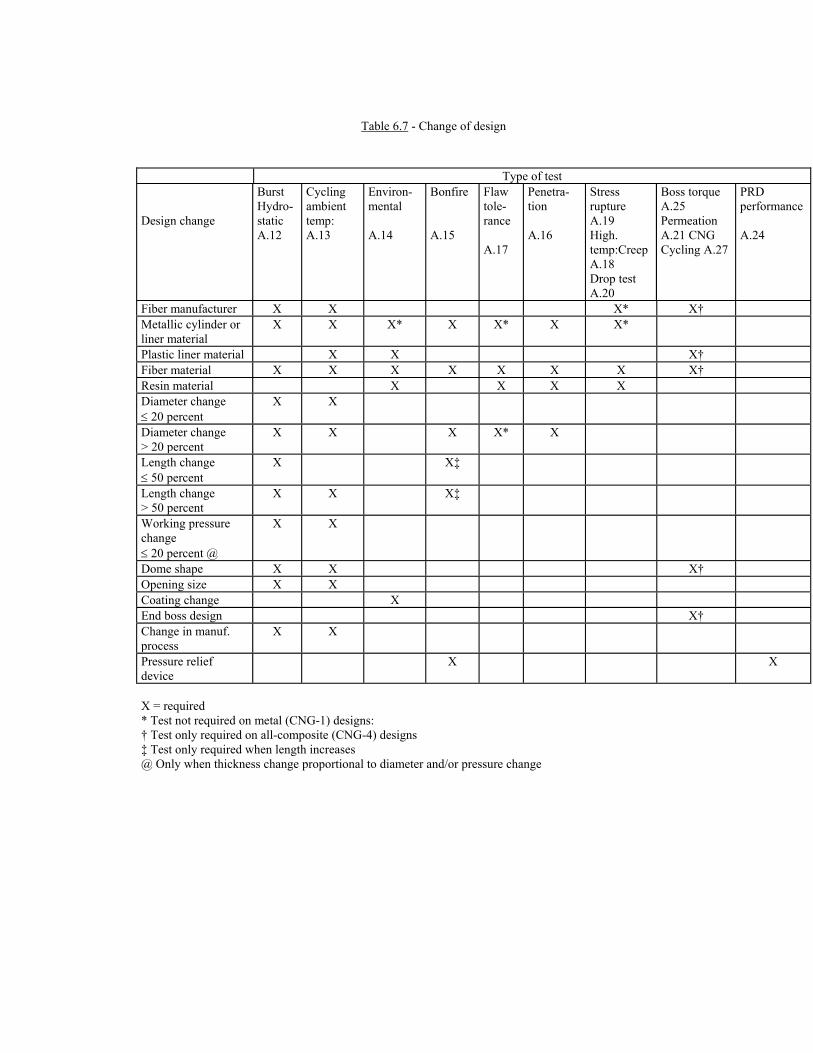
Table 6.7 - Change of design
Type of test Design change
Burst Hydro-static A.12
Cycling ambient temp: A.13
Environ-mental A.14
Bonfire A.15
Flaw tole-rance A.17
Penetra-tion A.16
Stress rupture A.19 High. temp:Creep A.18 Drop test A.20
Boss torque A.25 Permeation A.21 CNG Cycling A.27
PRD performance A.24
Fiber manufacturer X X X* X† Metallic cylinder or liner material
X X X* X X* X X*
Plastic liner material X X X† Fiber material X X X X X X X X† Resin material X X X X Diameter change 20 percent
X X
Diameter change > 20 percent
X X X X* X
Length change 50 percent
X X‡
Length change > 50 percent
X X X‡
Working pressure change 20 percent @
X X
Dome shape X X X† Opening size X X Coating change X End boss design X† Change in manuf. process
X X
Pressure relief device
X X
X = required * Test not required on metal (CNG-1) designs: † Test only required on all-composite (CNG-4) designs ‡ Test only required when length increases @ Only when thickness change proportional to diameter and/or pressure change

78
7. TYPE CNG-1 METAL CYLINDERS 7.1. General
The design shall identify the maximum size of an allowable defect at any point in the cylinder which will not grow to a critical size within the specified retest period, or service life if no retest is specified, of a cylinder operating to the working pressure. Determination of leak-before-break (LBB) performance shall be done in accordance with the appropriate procedures defined in paragraph A.6 (Appendix A). Allowable defect size shall be determined in accordance with paragraph 6.15.2. above. Cylinders designed in accordance with ISO 9809 and meeting all the requirements therein are only required to meet the materials test requirements of paragraph 6.3.2.4. above and the design qualification test requirements of paragraph 7.5., except paragraphs 7.5.2. and 7.5.3. below.
7.2. Stress analysis The stresses in the cylinder shall be calculated for 2 MPa, 20 MPa, test pressure and design burst
pressure. The calculations shall use suitable analysis techniques using thin-shell theory that takes into account out-of-plane bending of the shell to establish stress distributions at the neck, transition regions and the cylindrical part of the cylinder.
7.3. Manufacturing and production test requirements 7.3.1. General
The ends of aluminium cylinders shall not be closed by a forming process. The base ends of steel cylinders which have been closed by forming, except those cylinders designed in accordance with ISO 9809, shall be NDE inspected or equivalent. Metal shall not be added in the process of closure at the end. Each cylinder shall be examined before end forming operations for thickness and surface finish. After end forming the cylinders shall be heat treated to the hardness range specified for the design. Localized heat treatment is not permitted. When a neck ring, foot ring or attachments for support are provided, it shall be of material compatible with that of the cylinder and shall be securely attached by a method other than welding, brazing or soldering.
7.3.2. Non-destructive examination
The following tests shall be carried out on each metallic cylinder: (a) Hardness test in accordance with paragraph A.8 (Appendix A), (b) Ultrasonic examination, in accordance with BS 5045, Part 1, Annex I, or demonstrated
equivalent NDT method, to ensure that the maximum defect size does not exceed the size specified in the design as determined in accordance with paragraph 6.15.2. above.
7.3.3. Hydrostatic pressure testing Each finished cylinder shall be hydrostatically pressure tested in accordance with paragraph A.11
(Appendix A). 7.4. Cylinder batch tests

Batch testing shall be conducted on finished cylinders that are representative of normal production and are complete with identification marks. Two cylinders shall be randomly selected from each batch. If more cylinders are subjected to the tests than are required by this annex, all results shall be documented. The following tests shall as a minimum be carried out on these.
(a) Batch materials tests. One cylinder, or a heat treat witness sample representative of a finished
cylinder, shall be subjected to the following tests: (i) Critical dimensions checked against the design; (ii) One tensile test in accordance with paragraph A.1 (Appendix A) and meet the
requirements of the design; (iii) For steel cylinders, three impact tests in accordance with paragraph A.2 (Appendix A)
and meet the requirements of paragraph 6.3.2.3. above; (iv) When a protective coating is a part of the design, the coating shall be tested in
accordance with paragraph A.9.2 (Appendix A);
All cylinders represented by a batch test which fail to meet the specified requirements shall follow the procedures specified in paragraph 6.16. above. Where the coating fails to meet the requirements of paragraph A.9.2 (Appendix A), the batch shall be 100 percent inspected to remove similarly defective cylinders. The coating on all defective cylinders may be stripped and recoated. The coating batch test shall then be repeated;
(b) Batch burst test. One cylinder shall be hydrostatically pressurized to burst in accordance with
paragraph A.12 (Appendix A).
If the burst pressure is less than the minimum calculated burst pressure the procedures specified in paragraph 6.16. above shall be followed.
(c) Periodic pressure cycling test. Finished cylinders shall be pressure cycled in accordance with
paragraph A.13 (Appendix A) at a test frequency defined as follows: (i) one cylinder from each batch shall be pressure cycled for a total of 1,000 times the
specified service life in years, with a minimum 15,000 cycles; (ii) on 10 sequential production batches of a design family (i.e. similar materials and
processes), should none of the pressure cycled cylinders in (i) above leak or rupture in less than 1,500 cycles times the specified life in years (minimum 22,500 cycles) then the pressure cycle test can be reduced to one cylinder from every 5 batches of production;
(iii) on 10 sequential production batches of a design family, should none of the pressure cycled cylinders in (i) above leak or rapture in less than 2,000 cycles times the specified service life in years (minimum 30,000 cycles) then the pressure cycle test can be reduced to one cylinder from every 10 batches of production;
(iv) should more than 6 months have expired since the last batch of production. then a cylinder from the next batch of production shall be pressure cycle tested in order to maintain the reduced frequency of batch testing in (ii) or (iii) above.
(v) should any reduced frequency pressure cycle test cylinder in (ii) or (iii) above fail to meet the required number of pressure cycles (minimum 22,500 or 30,000 pressure cycles, respectively,) then it shall be necessary to repeat the batch pressure cycle test frequency in (i) for a minimum 10 production batches in order to re-establish the reduced frequency of batch pressure cycle testing in (ii) or (iii) above.
(vi) should any cylinder in (i), (ii), or (iii) above fail to meet the minimum cycle life requirement of 1,000 cycles times the specified service life in years (minimum 15,000 cycles), then the cause of failure shall be determined and corrected following the procedures in paragraph 6.16. The pressure cycle test shall then be repeated on an additional three cylinders from that batch. Should any of the three additional cylinders fail to meet the minimum pressure cycling requirement of 1,000 cycles times the
80
specified service life in years, then the batch shall be rejected. 7.5. Cylinder design qualification tests 7.5.1. General Qualification testing shall be conducted on finished cylinders which are representative of normal
production and complete with identification marks. Selection, witnessing and documentation of the results shall be in accordance with paragraph 6.13. above.
7.5.2. Hydrostatic pressure burst test Three representative cylinders shall be hydrostatically pressurized to failure in accordance with
paragraph A.12. (Appendix A to this annex). The cylinder burst pressures shall exceed the minimum burst pressure calculated by the stress analysis for the design, and shall be at least 45 MPa.
7.5.3. Ambient temperature pressure cycling test. Two finished cylinders shall be pressure cycled at ambient temperature in accordance with paragraph
A.13 (Appendix A) to failure, or to a minimum of 45,000 cycles. The cylinders shall not fail before reaching the specified service life in years times 1,000 cycles. Cylinders exceeding 1,000 cycles times the specified service life in years shall fail by leakage and not by rupture. Cylinders which do not fail within 45,000 cycles shall be destroyed either by continuing the cycling until failure occurs, or by hydrostatically pressurizing to burst. The number of cycles to failure and the location of the failure initiation shall be recorded.
7.5.4. Bonfire test Tests shall be conducted in accordance with paragraph A.15 (Appendix A) and meet the requirements
therein. 7.5.5. Penetration test Test shall be conducted in accordance with paragraph A.16 (Appendix A) and meet the requirements
therein. 7.5.6. LBB performance For cylinder designs not exceeding 45,000 cycles when tested as per paragraph 7.5.3. above, LBB
performance tests shall be conducted in accordance with A.6 and meet the requirements therein. 8. TYPE CNG-2 HOOP-WRAPPED CYLINDERS 8.1. General
During pressurization, this type of cylinder design has a behavior in which the displacements of the composite over-wrap and the metal liner are linearly superimposed. Due to different techniques of manufacture, this annex does not give a definite method for design. Determination of the leak-before-break (LBB) performance shall be in accordance with the appropriate procedures defined in paragraph A.6 (Appendix A). Allowable defect size shall be determined in accordance with paragraph 6.15.2. above.
8.2. Design requirements

8.2.1. Metal liner The metal liner shall have a minimum actual burst pressure of 26 MPa. 8.2.2. Composite over-wrap
The tensile stress in the fibers shall meet the requirements of paragraph 6.5. above. 8.2.3. Stress analysis
The stresses in the composite and in the liner after prestress shall be calculated. The pressures used for these calculations shall be zero, 2 MPa, 20 MPa test pressure and design burst pressure. The calculations shall use suitable analysis techniques using thin-shell theory taking account of non-linear material behavior of the liner to establish stress distributions at the neck, transition regions and the cylindrical part of the liner. For designs using auto-frettage to provide prestress, the limits within which the auto-frettage pressure must fall shall be calculated. For designs using controlled tension winding to provide prestress, the temperature at which it is performed, the tension required in each layer of composite and the consequent prestress in the liner shall be calculated.
8.3. Manufacturing requirements 8.3.1. General The composite cylinder shall be fabricated from a liner over-wrapped with continuous filament
windings. Filament winding operations shall be computer or mechanically controlled. The filaments shall be applied under controlled tension during winding. After winding is complete, thermosetting resins shall be cured by heating, using a predetermined and controlled time-temperature profile.
8.3.2. Liner The manufacture of a metallic liner shall meet the requirements given under paragraph 7.3. above for
the appropriate type of liner construction. 8.3.3. Over-wrap The cylinders shall be fabricated in a filament winding machine. During winding the significant
variables shall be monitored within specified tolerances, and documented in a winding record. These variables can include but are not limited to:
(a) fiber type including sizing; (b) manner of impregnation; (c) winding tension; (d) winding speed; (e) number of rovings; (f) band width; (g) type of resin and composition; (h) temperature of the resin; (i) temperature of the liner.
8.3.3.1. Curing of thermosetting resins

82
If a thermosetting resin is used, the resin shall be cured after filament winding. During the curing, the curing cycle (i.e. the time-temperature history) shall be documented. The curing temperature shall be controlled and shall not affect the material properties of the liner. The maximum curing temperature for cylinders with aluminum liners is 177 C.
8.3.4. Auto-frettage Auto-frettage, if used, shall be carried out before the hydrostatic pressure test. The auto-frettage
pressure shall be within the limits established in paragraph 8.2.3. above, and the manufacturer shall establish the method to verify the appropriate pressure.
8.4. Production test requirements 8.4.1. Non-destructive examination Non-destructive examinations shall be carried out in accordance with a recognized ISO or an
equivalent standard. The following tests shall be carried out on each metallic liner:
(a) Hardness test in accordance with paragraph A.8 (Appendix A); (b) Ultrasonic examination, in accordance with BS 5045, Part 1, Annex 1B, or demonstrated
equivalent NDT method, to ensure that the maximum defect size does not exceed the size specified in the design.
8.4.2. Hydrostatic pressure testing Each finished cylinder shall be hydrostatically pressure tested in accordance with paragraph A.11
(Appendix A). The manufacturer shall define the appropriate limit of permanent volumetric expansion for the test pressure used, but in no case shall the permanent expansion exceed 5percent of the total volumetric expansion at test pressure. Any cylinders not meeting the defined rejection limit shall be rejected and either destroyed or used for batch rest purposes.
8.5. Cylinder batch tests 8.5.1. General Batch testing shall be conducted on finished cylinders which are representative of normal production
and are complete with identification marks. Two cylinders, or a cylinder and a liner as appropriate, shall be randomly selected from each batch. If more cylinders are subjected to the tests than are required by this annex, all results shall be documented. The following tests shall as a minimum be carried out on these.
Where defects are detected in over-wrapping before any auto-frettage or hydrostatic pressure testing, the over-wrapping may be completely removed and replaced;
(a) Batch materials tests. One cylinder, or liner, or heat treat witness sample that is representative
of a finished cylinder, shall be subjected to the following tests: (i) Dimensions checked against the design; (ii) One tensile test in accordance with paragraph A.1 (Appendix A) and meet the
requirements of the design; (iii) For steel liners, three impact tests in accordance with paragraph A.2 (Appendix A) and
meet the requirements of the design; (iv) When a protective coating is a part of the design, the coating shall be tested in
accordance with paragraph A.9.2 (Appendix A) and meet the requirements therein. All

cylinders or liners represented by a batch test which fails to meet the requirements specified shall follow the procedures specified in paragraph 6.16. above.
Where the coating fails to meet the requirements of paragraph A.9.2. (Appendix A), the batch shall be 100 percent inspected to remove similarly defective cylinders. The coating on all defective cylinders may be stripped using a method that does not affect the integrity of the composite wrapping, and recoated. The coating batch test shall then be repeated.
(b) Batch burst test. One cylinder shall be tested in accordance with the requirements of paragraph
7.4(b) above; (c) Periodic pressure cycling test. In accordance with the requirements of paragraph 7.4(c) above.
8.6. Cylinder design qualification tests 8.6.1. General Qualification testing shall be conducted on cylinders which are representative of normal production
and complete with identification marks. Selection, witnessing and documentation of the results shall comply with paragraph 6.13. above.
8.6.2. Hydrostatic pressure burst test
(a) One liner shall be hydrostatically burst in accordance with paragraph A.12. (Appendix A). The burst pressure shall exceed the minimum burst pressure specified for the liner design;
(b) Three cylinders shall be hydrostatically burst in accordance with paragraph A.12 (Appendix A). Cylinder burst pressures shall exceed the specified minimum burst pressure established by the stress analysis for the design, in accordance with table 6.3, and in no case less than the value necessary to meet the stress ratio requirements of paragraph 6.5 above.
8.6.3. Ambient temperature pressure cycling test Two finished cylinders shall be pressure cycle tested at ambient temperature in accordance with
paragraph A.13 (Appendix A) to failure, or to a minimum of 45,000 cycles. The cylinders shall not fail before reaching the specified service life in years times 1,000 cycles. Cylinders exceeding 1000 cycles times the specified service life in years shall fail by leakage and not by rupture. Cylinders that do not fail within 45,000 cycles shall be destroyed either by continuing the cycling until failure occurs, or by hydrostatically pressurizing to burst. Cylinders exceeding 45,000 cycles are permitted to fail by rupture. The number of cycles to failure and the location of the failure initiation shall be recorded.
8.6.4. Acid environment test One cylinder shall be tested in accordance with paragraph A.14 (Appendix A) and meet the
requirements therein. An optional environmental test is included in the informative Appendix H to this annex.
8.6.5. Bonfire test Finished cylinders shall be tested in accordance with paragraph A.15 (Appendix A) and meet the
requirements therein. 8.6.6. Penetration test One finished cylinder shall be tested in accordance with paragraph A.16 (Appendix A) and meet the
requirements therein.

84
8.6.7. Flaw tolerance tests One finished cylinder shall be tested in accordance with paragraph A.17 (Appendix A) and meet the
requirements therein. 8.6.8. High temperature creep test In designs where the glass transition temperature of the resin does not exceed the maximum design
material temperature by at least 20 C, one cylinder shall be tested in accordance with paragraph A.18 (Appendix A) and meet the requirements therein.
8.6.9. Accelerated stress rupture test One finished cylinder shall be tested in accordance with paragraph A.19 (Appendix A) and meet the
requirements therein. 8.6.10. LBB performance For cylinder designs not exceeding 45,000 cycles when tested as per paragraph 8.6.3. above, LBB
performance tests shall be conducted in accordance with A.6 and meet the requirements therein. 8.6.11. Extreme temperature pressure cycling test One finished cylinder shall be tested in accordance with paragraph A.7 (Appendix A) and meet the
requirements therein. 9. TYPE CNG-3 FULLY-WRAPPED CYLINDERS 9.1. General During pressurization, this type of cylinder has a behavior in which the displacements of the composite
over-wrap and the liner are superimposed. Due to different techniques of manufacture, this annex does not give a definite method for design; Determination of the leak-before-break (LBB) performance shall be in accordance with the appropriate procedures defined in paragraph A.6 (Appendix A). Allowable defect size shall be determined in accordance with paragraph 6.15.2. above.
9.2. Design requirements 9.2.1. Metal liner The compressive stress in the liner at zero pressure and 15 C shall not cause the liner to buckle or
crease. 9.2.2. Composite over-wrap The tensile stress in the fibers shall meet the requirements of paragraph 6.5. above. 9.2.3. Stress analysis The stresses in the tangential and longitudinal direction of the cylinder in the composite and in the
liner after pressure shall be calculated. The pressure used for these calculations shall be zero, working pressure, 10 percent of working pressure, test pressure and design burst pressure. The limits within which autofrettaging pressure must fall shall be calculated, The calculations shall use suitable analysis

techniques using thin-shell theory taking account of non-linear material behavior of the liner to establish stress distributions at the neck, transition regions and the cylindrical part of the liner.
9.3. Manufacturing requirements
Manufacturing requirements shall be in accordance with paragraph 8.3. above except that the over-wrap shall also include helically wound filaments.
9.4. Production test requirements Production test requirements shall be in accordance with the requirements of paragraph 8.4. above. 9.5. Cylinder batch tests The batch tests shall be in accordance with the requirements of paragraph 8.5. above. 9.6. Cylinder design qualification tests Cylinder design qualification tests shall be in accordance with the requirements of paragraph 8.6.
above, and paragraph 9.6.1. below, except that the liner burst in paragraph 8.6. above is not required. 9.6.1. Drop test One or more finished cylinders shall be drop tested in accordance with paragraph A.20 (Appendix A). 10. TYPE CNG-4 ALL-COMPOSITE CYLINDERS 10.1. General This annex does not give a definite method for the design of cylinders with polymeric liners because of
the variety of cylinder designs possible. 10.2. Design requirements
Design calculations shall be used to provide justification of design adequacy. The tensile stresses in the fibers shall meet the requirements of paragraph 6.5. above. Tapered and straight threads in accordance with paragraph 6.10.2. or 6.10.3. above shall be used on the metal end bosses. Metal end bosses with threaded openings shall be able to withstand a torque force of 500 Nm, without damaging the integrity of the connection to the non-metallic liner. The metal end bosses connected to the non-metallic liner shall be of a material compatible with the service conditions specified in paragraph 4 of this annex.
10.3. Stress analysis The stresses in the tangential and longitudinal direction of the cylinder in the composite and in the
liner shall be calculated. The pressures used for these calculations shall be zero, working pressure, test pressure and design burst pressure. The calculations shall use suitable analysis techniques to establish stress distribution throughout the cylinder.
10.4. Manufacturing requirements Manufacturing requirements shall be in accordance with paragraph 8.3. above except that the curing
temperature for thermosetting resins shall be at least 10 C below the softening temperature of the

86
plastic liner. 10.5. Production test requirements 10.5.1. Hydrostatic pressure testing Each finished cylinder shall be hydrostatically pressure tested in accordance with paragraph A.11
(Appendix A). The manufacturer shall define the appropriate limit of elastic expansion for the test pressure used, but in no case shall the elastic expansion of any cylinder exceed the average batch value by more than 10 percent. Any cylinders not meeting the defined rejection limit shall be rejected and either destroyed or used for batch test purposes.
10.5.2. Leak testing Each finished cylinder shall be leak tested in accordance with paragraph A.10 (Appendix A) and meet
the requirements therein. 10.6. Cylinder batch tests 10.6.1. General Batch testing shall be conducted on finished cylinders which are representative of normal production
and are complete with identification marks. One cylinder shall be randomly selected from each batch. If more cylinders are subjected to the tests than are required by this annex, all results shall be documented. The following tests shall as a minimum be carried out on these.
(a) Batch materials test
One cylinder, or liner, or liner witness sample that is representative of a finished cylinder, shall be subjected to the following tests: (i) Dimensions checked against the design; (ii) One tensile test of the plastic liner in accordance with paragraph A.22 (Appendix A)
and meet the requirements of the design; (iii) The melt temperature of the plastic liner shall be tested in accordance with paragraph
A.23 (Appendix A), and meet the requirements of the design; (iv) When a protective coating is a part of the design, the coating shall be tested in
accordance with paragraph A.9.2 (Appendix A). Where the coating fails to meet the requirements of paragraph A.9.2 (Appendix A), the batch shall be 100 percent inspected to remove similarly defective cylinders. The coating on all defective cylinders may be stripped using a method that does not affect the integrity of the composite wrapping, and recoated. The coating batch test shall then be repeated.
(b) Batch burst test
One cylinder shall be tested in accordance with the requirements of paragraph 7.4(b) above; (c) Periodic pressure cycling test
On one cylinder the end boss shall be torque tested to 500 Nm in accordance with the test method in paragraph A.25 (Appendix A). The cylinder shall then be pressure cycle tested in accordance with the procedures provided in paragraph 7.4(c) above.
Following the required pressure cycling, the cylinder shall be leak tested in accordance with the

method described in paragraph A.10 (Appendix A) and meet the requirements therein. 10.7. Cylinder design qualification tests 10.7.1. General Cylinder design qualification tests shall be in accordance with the requirements of paragraphs 8.6.,
10.7.2., 10.7.3. and 10.7.4. of this annex, except that the LBB performance in paragraph 8.6.10. above is not required.
10.7.2. Boss torque test One cylinder shall be tested in accordance with paragraph A.25 (Appendix A). 10.7.3. Permeation test One cylinder shall be tested for permeation in accordance with paragraph A.21 (Appendix A) and meet
the requirements therein. 10.7.4. Natural gas cycling test One finished cylinder shall be tested in accordance with paragraph A.27 (Appendix A) and meet the
requirements therein. 11. MARKING 11.1. Provision of marking On each cylinder the manufacturer shall provide clear permanent markings not less than 6 mm high.
Marking shall be made either by labels incorporated into resin coatings, labels attached by adhesive, low stress stamps used on the thickened ends of type CNG-1 and CNG-2 designs, or any combination of the above. Adhesive labels and their application shall be in accordance with ISO 7225, or an equivalent Standard. Multiple labels are allowed and should be located such that they are not obscured by mounting brackets. Each cylinder complying with this annex shall be marked as follows:
(a) Mandatory information:
(i) "CNG ONLY"; (ii) "DO NOT USE AFTER XX/XXXX", where "XX/XXX" identifies the month and year
of expiry 1/; (iii) Manufacturer’s identification; (iv) Cylinder identification (applicable part number and a serial number unique for every
cylinder); (v) Working pressure and temperature; (vi) ECE Regulation number, along with cylinder type and certification registration number; (vii) The pressure relief devices and/or valves, which are qualified for, use with the cylinder
or the means for obtaining information on qualified fire protection systems; (viii) When labels are used, all cylinders shall have a unique identification number stamped
on an exposed metal surface to permit tracing in the event that the label is destroyed; (b) Non-mandatory information:
1/ The expiry date shall not exceed the specified service life. The expiry date may be applied to the cylinder at the time of dispatch, provided that the cylinders have been stored in a dry location without internal pressure.
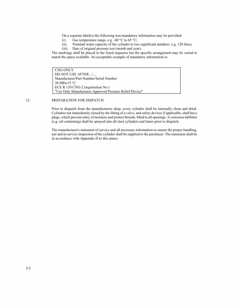
88
On a separate label(s) the following non-mandatory information may be provided: (i) Gas temperature range, e.g. -40 C to 65 C; (ii) Nominal water capacity of the cylinder to two significant numbers. e.g. 120 litres; (iii) Date of original pressure test (month and year).
The markings shall be placed in the listed sequence but the specific arrangement may be varied to match the space available. An acceptable example of mandatory information is:
CNG ONLY DO NOT USE AFTER ../.... Manufacturer/Part Number/Serial Number 20 MPa/15 C ECE R 110 CNG-2 (registration No.) "Use Only Manufacturer-Approved Pressure Relief Device"
12. PREPARATION FOR DISPATCH
Prior to dispatch from the manufacturers shop, every cylinder shall be internally clean and dried. Cylinders not immediately closed by the fitting of a valve, and safety devices if applicable, shall have plugs, which prevent entry of moisture and protect threads, fitted to all openings. A corrosion inhibitor (e.g. oil-containing) shall be sprayed into all steel cylinders and liners prior to dispatch. The manufacturer's statement of service and all necessary information to ensure the proper handling, use and in-service inspection of the cylinder shall be supplied to the purchaser. The statement shall be in accordance with Appendix D to this annex.
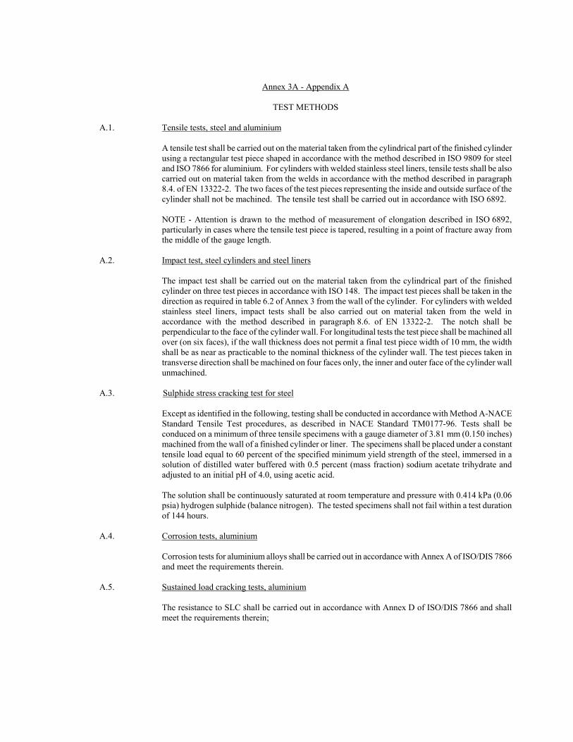
Annex 3A - Appendix A
TEST METHODS A.1. Tensile tests, steel and aluminium A tensile test shall be carried out on the material taken from the cylindrical part of the finished cylinder
using a rectangular test piece shaped in accordance with the method described in ISO 9809 for steel and ISO 7866 for aluminium. For cylinders with welded stainless steel liners, tensile tests shall be also carried out on material taken from the welds in accordance with the method described in paragraph 8.4. of EN 13322-2. The two faces of the test pieces representing the inside and outside surface of the cylinder shall not be machined. The tensile test shall be carried out in accordance with ISO 6892.
NOTE - Attention is drawn to the method of measurement of elongation described in ISO 6892,
particularly in cases where the tensile test piece is tapered, resulting in a point of fracture away from the middle of the gauge length.
A.2. Impact test, steel cylinders and steel liners The impact test shall be carried out on the material taken from the cylindrical part of the finished
cylinder on three test pieces in accordance with ISO 148. The impact test pieces shall be taken in the direction as required in table 6.2 of Annex 3 from the wall of the cylinder. For cylinders with welded stainless steel liners, impact tests shall be also carried out on material taken from the weld in accordance with the method described in paragraph 8.6. of EN 13322-2. The notch shall be perpendicular to the face of the cylinder wall. For longitudinal tests the test piece shall be machined all over (on six faces), if the wall thickness does not permit a final test piece width of 10 mm, the width shall be as near as practicable to the nominal thickness of the cylinder wall. The test pieces taken in transverse direction shall be machined on four faces only, the inner and outer face of the cylinder wall unmachined.
A.3. Sulphide stress cracking test for steel
Except as identified in the following, testing shall be conducted in accordance with Method A-NACE Standard Tensile Test procedures, as described in NACE Standard TM0177-96. Tests shall be conduced on a minimum of three tensile specimens with a gauge diameter of 3.81 mm (0.150 inches) machined from the wall of a finished cylinder or liner. The specimens shall be placed under a constant tensile load equal to 60 percent of the specified minimum yield strength of the steel, immersed in a solution of distilled water buffered with 0.5 percent (mass fraction) sodium acetate trihydrate and adjusted to an initial pH of 4.0, using acetic acid. The solution shall be continuously saturated at room temperature and pressure with 0.414 kPa (0.06 psia) hydrogen sulphide (balance nitrogen). The tested specimens shall not fail within a test duration of 144 hours.
A.4. Corrosion tests, aluminium Corrosion tests for aluminium alloys shall be carried out in accordance with Annex A of ISO/DIS 7866
and meet the requirements therein. A.5. Sustained load cracking tests, aluminium The resistance to SLC shall be carried out in accordance with Annex D of ISO/DIS 7866 and shall
meet the requirements therein;

90
A.6. Leak-Before-Break (LBB) performance test
Three finished cylinders shall be pressure cycled between not more than 2 MPa and nor less than 30 MPa at a rate not to exceed 10 cycles per minute. All cylinders shall fail by leakage.
A.7. Extreme temperature pressure cycling Finished cylinders, with the composite wrapping free of any protective coating, shall be cycle tested,
without showing evidence of rupture, leakage, or fiber unraveling, as follows:
(a) Condition for 48 hours at zero pressure, 65 C or higher, and 95 percent or greater relative humidity. The intent of this requirement shall be deemed met by spraying with a fine spray or mist of water in a chamber held at 65 C;
(b) Hydrostatically pressurized for 500 cycles times the specified service life in years between not more than 2 MPa and not less than 26 MPa at 65 or higher and 95 percent humidity;
(c) Stabilize at zero pressure and ambient temperature; (d) Then pressurize from not more than 2 MPa to not less than 20 MPa for 500 cycles times the
specified service life in years at -40 C or lower; The pressure cycling rate of b) shall not exceed 10 cycles per minute. The pressure cycling rate of d) shall not exceed 3 cycles per minute unless a pressure transducer is installed directly within the cylinder. Adequate recording instrumentation shall be provided to ensure the minimum temperature of the fluid is maintained during the low temperature cycling. Following pressure cycling at extreme temperatures, cylinders shall be hydrostatically pressured to failure in accordance with the hydrostatic burst test requirements, and achieve a minimum burst pressure of 85 percent of the minimum design burst pressure. For type CNG-4 designs, prior to the hydrostatic burst test the cylinder shall be leak tested in accordance with paragraph A.10 below.
A.8. Brinell hardness test Hardness tests shall be carried out on the parallel wall at the centre and a domed end of each cylinder
or liner in accordance with ISO 6506. The test shall be carried out after the final heat treatment and the hardness values thus determined shall be in the range specified for the design.
A.9. Coating tests (mandatory if paragraph 6.12 c) of Annex 3 is used) A.9.1. Coating performance tests Coatings shall be evaluated using the following test methods, or using equivalent National Standards.
(a) adhesion testing in accordance with LSO 4624 using Method A or B as applicable. The coating shall exhibit an adhesion rating of either 4A or 4B, as applicable;
(b) flexibility in accordance with ASTM D522 Mandrel Bend Test of Attached Organic Coatings, using Test Method B with a 12.7 mm (0.5 in) mandrel at the specified thickness at -20 C. Samples for the flexibility test shall be prepared in accordance with the ASTM D522 standard. There shall not be any visually apparent cracks;
(c) impact resistance in accordance with ASTM D2794 Test method for Resistance of Organic Coatings to the Effects of Rapid Deformation (Impact). The coating at room temperature shall pass a forward impact test of 18 J (160 in-lbs);
(d) chemical resistance when tested in general accordance with ASTM D1308 Effect of Household Chemicals on Clear and Pigmented Organic Finishes. The tests shall be conducted using the

Open Spot Test Method and 100 hour exposure to a 30 percent sulfuric acid solution (battery acid with a specific gravity of 1.219) and 24 hour exposure to a polyalkalene glycol (e.g. brake fluid). There shall be no evidence of lifting, blistering or softening of the coating. The adhesion shall meet a rating of 3 when tested in accordance with ASTM D3359;
(e) Minimum 1,000 hours exposure in accordance with ASTM G53 Practice for Operating Light- and Water-Exposure Apparatus (Fluorescent W-Condensation Type) for Exposure of non-metallic Materials. There shall be no evidence of blistering, and adhesion shall meet a rating of 3 when tested in accordance with ISO 4624. The maximum gloss loss allowed is 20 percent;
(f) minimum 500 hours exposure in accordance with ASTM B117 Test Method of Salt Spray (Fog) Testing. Undercutting shall not exceed 3 mm at the scribe mark, there shall be no evidence of blistering, and adhesion shall meet a rating of 3 when tested in accordance with ASTM D3359;
(g) resistance to chipping at room temperature using the ASTM D3170 Chipping Resistance of Coatings. The coating shall have a rating of 7A or better, and there shall not be any exposure of the substrate;
A.9.2. Coating batch tests
(a) Coating thickness
The thickness of the coating shall meet the requirements of the design when tested in accordance with ISO 2808;
(b) Coating adhesion
The coating adhesion strength shall be measured in accordance with ISO 4624, and shall have a minimum rating of 4 when measured using either Test Method A or B, as appropriate.
A.10. Leak test Type CNG-4 designs shall be leak tested using the following procedure (or an acceptable alternative);
(a) cylinders shall be thoroughly dried and pressurized to working pressure with dry air or nitrogen, and containing a detectable gas such as helium;
(b) any leakage measured at any point that exceeds 0.004 standard cm3/h shall be cause for rejection.
A.11. Hydraulic test One of the following two options shall be used: Option 1: Water jacket test
(a) The cylinder shall be hydrostatically tested to at least 1.5 times working pressure. In no case may the test pressure exceed the auto-frettage pressure;
(b) Pressure shall be maintained for a sufficiently long period (at least 30 seconds) to ensure complete expansion. Any internal pressure applied after auto-frettage and previous to the hydrostatic test shall not exceed 90 percent of the hydrostatic test pressure. If the test pressure cannot be maintained due to failure of the test apparatus, it is permissible to repeat the test at a pressure increased by 700 kPa. Not more than 2 such repeat rests are permitted;
(c) The manufacturer shall define the appropriate limit of permanent volumetric expansion for the test pressure used, but in no case shall the permanent expansion exceed 5 percent of the total volumetric expansion measured under the test pressure. For type CNG-4 designs, the elastic expansion shall be established by the manufacturer. Any cylinders not meeting the defined
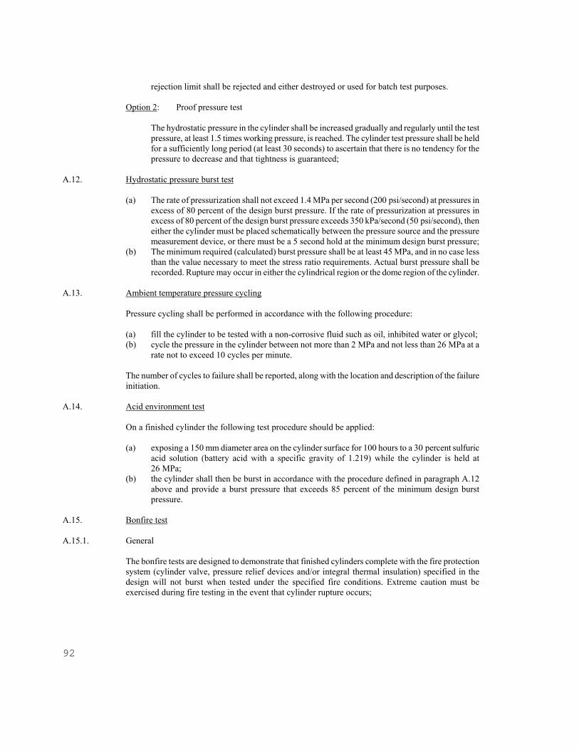
92
rejection limit shall be rejected and either destroyed or used for batch test purposes.
Option 2: Proof pressure test The hydrostatic pressure in the cylinder shall be increased gradually and regularly until the test pressure, at least 1.5 times working pressure, is reached. The cylinder test pressure shall be held for a sufficiently long period (at least 30 seconds) to ascertain that there is no tendency for the pressure to decrease and that tightness is guaranteed;
A.12. Hydrostatic pressure burst test
(a) The rate of pressurization shall not exceed 1.4 MPa per second (200 psi/second) at pressures in excess of 80 percent of the design burst pressure. If the rate of pressurization at pressures in excess of 80 percent of the design burst pressure exceeds 350 kPa/second (50 psi/second), then either the cylinder must be placed schematically between the pressure source and the pressure measurement device, or there must be a 5 second hold at the minimum design burst pressure;
(b) The minimum required (calculated) burst pressure shall be at least 45 MPa, and in no case less than the value necessary to meet the stress ratio requirements. Actual burst pressure shall be recorded. Rupture may occur in either the cylindrical region or the dome region of the cylinder.
A.13. Ambient temperature pressure cycling Pressure cycling shall be performed in accordance with the following procedure:
(a) fill the cylinder to be tested with a non-corrosive fluid such as oil, inhibited water or glycol; (b) cycle the pressure in the cylinder between not more than 2 MPa and not less than 26 MPa at a
rate not to exceed 10 cycles per minute. The number of cycles to failure shall be reported, along with the location and description of the failure initiation.
A.14. Acid environment test On a finished cylinder the following test procedure should be applied:
(a) exposing a 150 mm diameter area on the cylinder surface for 100 hours to a 30 percent sulfuric acid solution (battery acid with a specific gravity of 1.219) while the cylinder is held at 26 MPa;
(b) the cylinder shall then be burst in accordance with the procedure defined in paragraph A.12 above and provide a burst pressure that exceeds 85 percent of the minimum design burst pressure.
A.15. Bonfire test A.15.1. General The bonfire tests are designed to demonstrate that finished cylinders complete with the fire protection
system (cylinder valve, pressure relief devices and/or integral thermal insulation) specified in the design will not burst when tested under the specified fire conditions. Extreme caution must be exercised during fire testing in the event that cylinder rupture occurs;

A.15.2. Cylinder set-up Cylinders shall be placed horizontally with the cylinder bottom approximately 100 mm above the fire
source; Metallic shielding shall be used to prevent direct flame impingement on cylinder valves, fittings, and/or pressure relief devices. The metallic shielding shall not be in direct contact with the specified fire protection system (pressure relief devices or cylinder valve). Any failure during the test of a valve, fitting or tubing that is not part of the intended protection system for the design shall invalidate the result.
A.15.3. Fire source
A uniform fire source of 1.65 m length shall provide direct flame impingement on the cylinder surface across its entire diameter. Any fuel may be used for the fire source provided it supplies uniform heat sufficient to maintain the specified test temperatures until the cylinder is vented. The selection of fuel should take into consideration air pollution concerns. The arrangement of the fire shall be recorded in sufficient detail to ensure the rate of heat input to the cylinder is reproducible. Any failure or inconsistency of the fire source during a test invalidate the result;
A.15.4. Temperature and pressure measurements
Surface temperatures shall be monitored by at least three thermocouples located along the bottom of the cylinder and spaced not more than 0.75 m apart; Metallic shielding shall be used to prevent direct flame impingement on the thermocouples. Alternatively, thermocouples may be inserted into blocks of metal measuring less than 25 mm square. The pressure inside the cylinder shall be measured by a pressure sensor without modifying the configuration of the system under test.
Thermocouple temperatures and the cylinder pressure shall be recorded at intervals of every 30 seconds or less during the test.
A.15.5. General test requirements
Cylinders shall be pressurized with natural gas and tested in the horizontal position at both: (a) working pressure; (b) 25 percent of the working pressure. Immediately following ignition, the fire shall produce flame impingement on the surface of the cylinder along the 1.65 m length of the fire source and across the cylinder diameter. Within 5 minutes of ignition, at least one thermocouple shall indicate a temperature of at least 590 C. This minimum temperature shall be maintained for the remaining duration of the test.
A.15.6. Cylinders 1.65 m length or less The centre of the cylinder shall be positioned over the centre of the fire source; A.15.7. Cylinders greater than 1.65 m length If the cylinder is fitted with a pressure relief device at one end, the fire source shall commence at the
opposite end of the cylinder; If the cylinder is fitted with pressure relief devices at both ends, or at

94
more than one location along the length of the cylinder, the centre of the fire source shall be centered midway between the pressure relief devices that are separated by the greatest horizontal distance.
If the cylinder is additionally protected using thermal insulation, then two fire tests at service pressure shall be performed, one with the fire centered midway along the cylinder length, and the other with the fire commencing at one of the cylinder ends.
A.15.8. Acceptable results The cylinder shall vent through a pressure relief device. A.16. Penetration tests A cylinder pressurized to 20 MPa ± 1 MPa with compressed gas shall be penetrated by an armour
piercing bullet with a diameter of 7.62 mm or greater. The bullet shall completely penetrate at least one side wall of the cylinder. For type CNG-2, CNG-3 and CNG-4 designs, the projectile shall impact the side wall at an approximate angle of 45. The cylinder shall reveal no evidence of fragmentation failure. Loss of small pieces of material, each not weighing more than 45 grams, shall not constitute failure of the test. The approximate size of entrance and exit openings and their locations shall be recorded.
A.17. Composite flaw tolerance tests For type CNG-2, CNG-3 and CNG-4 designs only, one finished cylinder, complete with protective
coating, shall have flaws in the longitudinal direction cut into the composite. The flaws shall be greater than the visual inspection limits as specified by the manufacturer.
The flawed cylinder shall then be pressure cycled from not more than 2 MPa to not less than 26 MPa for 3,000 cycles, followed by an additional 12,000 cycles at ambient temperature; The cylinder shall not leak or rupture within the first 3,000 cycles, but may fail by leakage during the last 12,000 cycles. All cylinders which complete this test shall be destroyed.
A.18. High temperature creep test This test is required for all type CNG-4 designs, and all type CNG-2 and CNG-3 designs in which the
glass transition temperature of the resin matrix does not exceed the maximum design material temperature given in paragraph 4.4.2. of Annex 3 by at least 20 C. One finished cylinder shall be tested as follows: (a) The cylinder shall be pressurized to 26 MPa and held at a temperature of 100 C for not less
than 200 hours; (b) Following the test, the cylinder shall meet the requirements of the hydrostatic expansion test
A.11, the leak test A.10, and the burst test A.12 above. A.19. Accelerated stress rupture test For type CNG-2, CNG-3, and CNG-4 designs only, one cylinder free of protective coating shall be
hydrostatically pressurized to 26 MPa while immersed in water at 65 C. The cylinder shall be held at this pressure and temperature for 1,000 hours. The cylinder shall then be pressured to burst in accordance with the procedure defined in paragraph A.12 above except that the burst pressure shall exceed 85 percent of the minimum design burst pressure;
A.20. Impact damage test One or more finished cylinders shall be drop tested at ambient temperature without internal
pressurization or attached valves. The surface onto which the cylinders are dropped shall be a smooth,

horizontal concrete pad or flooring. One cylinder shall be dropped in a horizontal position with the bottom 1.8 m above the surface onto which it is dropped. One cylinder shall be dropped vertically on each end at a sufficient height above the floor or pad so that the potential energy is 488 J, but in no case shall the height of the lower end be greater than 1.8 m. One cylinder shall be dropped at a 45 angle onto a dome from a height such that the centre of gravity is at 1.8 m; however, if the lower end is closer to the ground than 0.6 m, the drop angle shall be changed to maintain a minimum height of 0.6 m and a centre of gravity of 1.8 m.
Following the drop impact, the cylinders shall be pressure cycled from not more than 2 MPa to not less
than 26 MPa bar for 1,000 cycles times the specified service life in years. The cylinders may leak but not rupture, during the cycling. Any cylinders completing the cycling test shall be destroyed;
A.21. Permeation test This test is only required on type CNG-4 designs. One finished cylinder shall be filled with
compressed natural gas or a 90 percent nitrogen/10 percent helium mixture to working pressure, placed in an enclosed sealed chamber at ambient temperature, and monitored for leakage for a time sufficient to establish a steady state permeation rate. The permeation rate shall be less than 0.25 ml of natural gas or helium per hour per liter water capacity of the cylinder.
A.22. Tensile properties of plastics The tensile yield strength and ultimate elongation of plastic liner material shall be determined at -50 C
using ISO 3628, and meet the requirements of paragraph 6.3.6. of Annex 3. A.23. Melting temperature of plastics Polymeric materials from finished liners shall be tested in accordance with the method described in
ISO 306, and meet the requirements of paragraph 6.3.6. of Annex 3. A.24. Pressure relief device requirements
Pressure relief device specified by the manufacturer shall be shown to be compatible with the service conditions listed in paragraph 4. of Annex 3 and through the following qualification tests: (a) One specimen shall be held at a controlled temperature of not less than 95 °C and a pressure
not less than test pressure (30 MPa) for 24 hours. At the end of this test there shall be no leakage or visible sign of extrusion of any fusible metal used in the design.
(b) One specimen shall be fatigue tested at a pressure cycling rate not to exceed 4 cycles per minute as follows: (i) held at 82 C while pressured for 10,000 cycles between 2 MPa and 26 MPa; (ii) held at -40 C while pressure for 10,000 cycles between 2 MPa and 20 MPa. At the end of this test there shall be no leakage, or any visible sign of extrusion of any fusible metal used in the design.
(c) Exposed brass pressure retaining components of pressure relief devices shall withstand, without stress corrosion cracking, a mercurous nitrate test as described in ASTM B154. The pressure relief device shall be immersed for 30 minutes in an aqueous mercurous nitrate solution containing 10 g of mercurous nitrate and 10 ml of nitric acid per liter of solution. Following the immersion, the pressure relief device shall be leak tested by applying an aerostatic pressure of 26 MPa for one minute during which time the component shall be checked for external leakage; Any leakage shall not exceed 200 cm3/h;
(d) Exposed stainless steel pressure retaining components of pressure relief devices shall be made of an alloy type resistant to chloride induced stress corrosion cracking;

96
A.25. Boss torque test
The body of the cylinder shall be restrained against rotation and a torque of 500 Nm shall be applied to each end boss of the cylinder, first in the direction to tighten a threaded connection, then in the untightening direction, and finally again in the tightening direction.
A.26. Resin shear strength Resin materials shall be tested on a sample coupon representative of the composite over-wrap in
accordance with ASTM D2344, or an equivalent National Standard. Following a 24-hour water boil the composite shall have minimum shear strength of 13.8 MPa.
A.27. Natural gas cycling test One finished cylinder shall be pressure cycled using compressed natural gas from less than 2 MPa to
working pressure for 300 cycles. Each cycle, consisting of the filling and venting of the cylinder, shall not exceed 1 hour. The cylinder shall be leak tested in accordance with paragraph A.10 above and meet the requirements therein. Following the completion of the natural gas cycling the cylinder shall be sectioned and the liner/end boss interface inspected for evidence of any deterioration, such as fatigue cracking or electrostatic discharge.
NOTE - Special consideration must be given to safety when conducting this test. Prior to conducting
this test, cylinders of this design must have successfully passed the test requirements of paragraph A.12 above (hydrostatic pressure burst test), paragraph 8.6.3. of Annex 3 (ambient temperature pressure cycling test) and paragraph A.21 above (permeation test). Prior to conducting this test, the specific cylinders to be tested must pass the test requirements of paragraph A.10 above (leak test).
A.28. (Deleted) A.29. Bend test, welded stainless steel liners Bend tests shall be carried out on material taken from the cylindrical part of a welded stainless steel
liner and tested in accordance with the method described in paragraph 8.5. of EN 13322-2. The test piece shall not crack when bent inwards around a former until the inside edges are not further apart than the diameter of the former.

Annex 3A - Appendix C
(Not allocated)

98
Annex 3A - Appendix D
REPORT FORMS
NOTE - This appendix is not a mandatory part of this annex. The following forms should be used:
(1) Report of Manufacture & Certificate of Conformance - Required to be clear, legible and in the format of Form 1.
(2) Report 1/ of Chemical Analysis of Material for Metallic Cylinders, Liners, or Bosses - Required essential elements, identification, etc.
(3) Report 1/ of Mechanical Properties of Material for Metallic Cylinders and Liners - Required to report all tests required by this Regulation.
(4) Report 1/ of Physical and Mechanical Properties of Materials for Non Metallic Liners - Required to report all tests and information required in this Regulation.
(5) Report 1/ of Composite Analysis - Required to report all tests and data required in this Regulation.
(6) Report of Hydrostatic Tests, Periodic Pressure Cycling and Burst Tests - Required to report test and data required in this Regulation.
Form 1: Report of Manufacturer and Certification of Conformance Manufactured by: Located at: Regulatory Registration Number: Manufacturers Mark and Number: Serial Number: from .......................................................... to ........................................................ inclusive Cylinder description: SIZE: Outside diameter: ................................................ mm; Length: .................................................. mm; Marks stamped on shoulder or on labels of the cylinders are:
(a) "CNG only": .............................................................................................................................................. (b) "DO NOT USE AFTER": ......................................................................................................................... (c) "Manufacturer's mark": ............................................................................................................................. (d) Serial and part number: ............................................................................................................................. (e) Working pressure in MPa: ........................................................................................................................
1/ Report forms 2 through 6 shall be developed by the manufacturer and must fully identify cylinders and requirements. Each report shall be signed by the Competent Authority and the manufacturer.
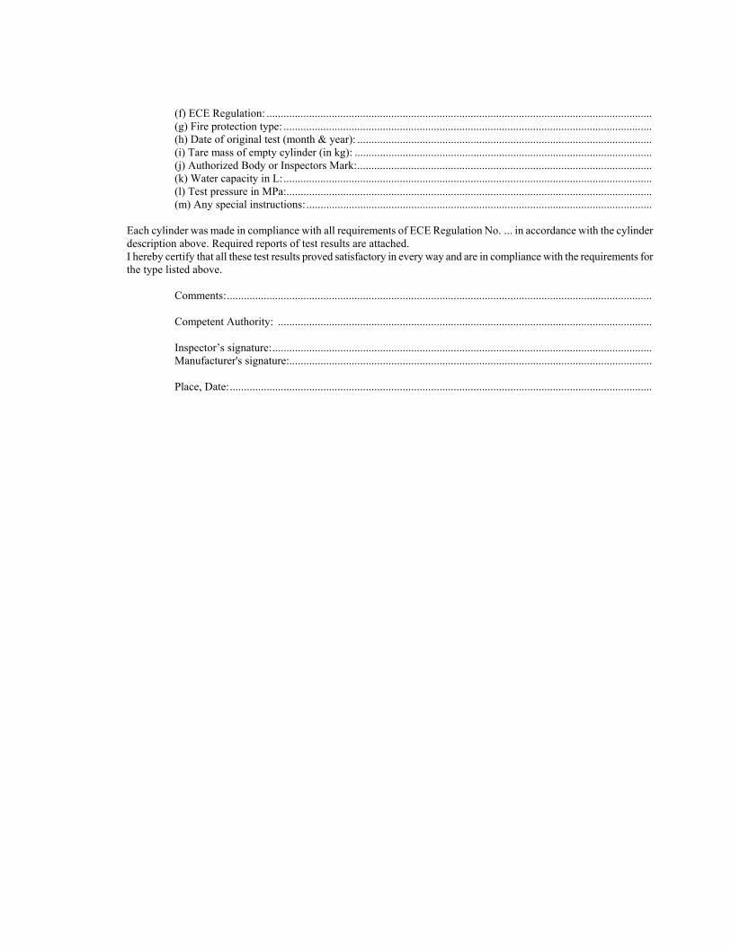
(f) ECE Regulation: ........................................................................................................................................ (g) Fire protection type: .................................................................................................................................. (h) Date of original test (month & year): ........................................................................................................ (i) Tare mass of empty cylinder (in kg): ......................................................................................................... (j) Authorized Body or Inspectors Mark: ........................................................................................................ (k) Water capacity in L: .................................................................................................................................. (l) Test pressure in MPa:................................................................................................................................. (m) Any special instructions: ..........................................................................................................................
Each cylinder was made in compliance with all requirements of ECE Regulation No. ... in accordance with the cylinder description above. Required reports of test results are attached. I hereby certify that all these test results proved satisfactory in every way and are in compliance with the requirements for the type listed above.
Comments: ...................................................................................................................................................... Competent Authority: .................................................................................................................................... Inspector’s signature: ...................................................................................................................................... Manufacturer's signature:................................................................................................................................ Place, Date: .....................................................................................................................................................
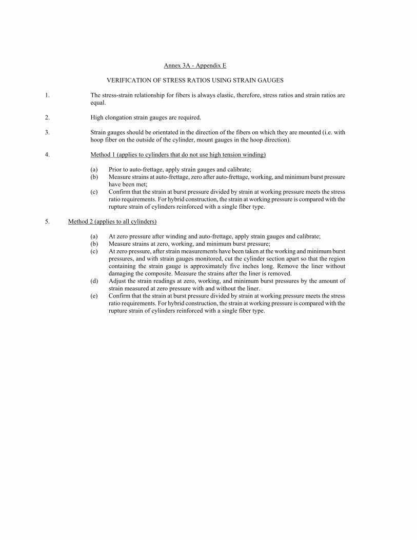
Annex 3A - Appendix E
VERIFICATION OF STRESS RATIOS USING STRAIN GAUGES 1. The stress-strain relationship for fibers is always elastic, therefore, stress ratios and strain ratios are
equal. 2. High elongation strain gauges are required. 3. Strain gauges should be orientated in the direction of the fibers on which they are mounted (i.e. with
hoop fiber on the outside of the cylinder, mount gauges in the hoop direction). 4. Method 1 (applies to cylinders that do not use high tension winding)
(a) Prior to auto-frettage, apply strain gauges and calibrate; (b) Measure strains at auto-frettage, zero after auto-frettage, working, and minimum burst pressure
have been met; (c) Confirm that the strain at burst pressure divided by strain at working pressure meets the stress
ratio requirements. For hybrid construction, the strain at working pressure is compared with the rupture strain of cylinders reinforced with a single fiber type.
5. Method 2 (applies to all cylinders)
(a) At zero pressure after winding and auto-frettage, apply strain gauges and calibrate; (b) Measure strains at zero, working, and minimum burst pressure; (c) At zero pressure, after strain measurements have been taken at the working and minimum burst
pressures, and with strain gauges monitored, cut the cylinder section apart so that the region containing the strain gauge is approximately five inches long. Remove the liner without damaging the composite. Measure the strains after the liner is removed.
(d) Adjust the strain readings at zero, working, and minimum burst pressures by the amount of strain measured at zero pressure with and without the liner.
(e) Confirm that the strain at burst pressure divided by strain at working pressure meets the stress ratio requirements. For hybrid construction, the strain at working pressure is compared with the rupture strain of cylinders reinforced with a single fiber type.

Annex 3A - Appendix F
FRACTURE PERFORMANCE METHODS F.1. Determination of fatigue sensitive sites The location and/orientation of fatigue failure in cylinders shall be determined by appropriate stress
analysis or by full scale fatigue tests on finished cylinders as required under the design qualification tests for each type of design. If finite element stress analysis is used, the fatigue sensitive site shall be identified based on the location and/orientation of the highest tensile principal stress concentration in the cylinder wall or liner at the working pressure.
F.2. Leak-Before-Break (LBB) F.2.1. Engineering critical assessment. This analysis may be carried out to establish that the finished cylinder
will leak in the event of a defect in the cylinder or liner growing into a through-wall crack. A leak-before-break assessment shall be performed at the cylinder side wall. If the fatigue sensitive location is outside the side wall, a leak-before-break assessment shall also be performed at that location using a Level II approach as outlined in BS PD6493. The assessment shall include the following steps:
(a) Measure the maximum length (i.e. major axis) of the resultant through-wall surface crack
(usually elliptical in shape) from the three cylinder cycle tested under the design qualification tests (according to paragraphs A.13 and A.14 of Appendix A) for each type of design. Use the longest crack length of the three cylinders in the analysis. Model a semi-elliptical through-wall crack with a major axis equal to twice the measured longest major axis and with a minor axis equal to 0.9 of wall thickness. The semi-elliptical crack shall be modeled at the locations specified in paragraph F.1. of Appendix F. The crack shall be oriented such that the highest tensile principal stress shall drive the crack;
(b) Stress levels in the wall/liner at 26 MPa obtained from the stress analysis as outlined in paragraph 6.6 of Annex 3 shall be used for the assessment. Appropriate crack driving forces shall be calculated using either Section 9.2 or 9.3 of BS PD6493;
(c) Fracture toughness of the finished cylinder or the liner from a finished cylinder, as determined at room temperature for aluminum and at -40 C for steel, shall be established using a standardized testing technique (either ISO/DIS 12737 or ASTM 813-89 or BS 7448) in accordance with Sections 8.4 and 8.5 of BS PD6493;
(d) Plastic collapse ratio shall be calculated in accordance with Section 9.4 of BS PD6493-91; (e) The modeled flaw shall be acceptable in accordance with Section 11.2 of BS PD6493-91.
F.2.2. LBB by flawed cylinder burst
A fracture test shall be performed by the cylinder side wall. If the fatigue sensitive locations as determined in paragraph F.1. (Appendix F) are outside the side wall, the fracture test shall also be performed at that location. The test procedure is as follows:
(a) Determination of leak-before-break flaw length The length of the LBB flaw at the fatigue sensitive site shall be twice the length of the
maximum length measured of the resultant through-wall surface crack from the three cylinders cycle tested to failure under the design qualification tests for each type of design;
(b) Cylinder flaws For type CNG-1 designs having fatigue sensitive site in the cylindrical part in the axial
direction, external flaws shall be machined longitudinally, approximately at mid-length of the
102
cylindrical part of the cylinder. The flaws shall be located at minimum wall thickness of the midsection based on thickness measurements at four points around the cylinder. For type CNG-1 designs having fatigue sensitive site outside the cylindrical part, the LBB flaw shall be introduced at the internal surface of the cylinder along the fatigue sensitive orientation. For type CNG-2 and CNG-3 designs the LBB flaw shall be introduced in the metal liner;
For flaws to be tested by monotonic pressure, the flaw cutter shall be approximately 12.5 mm thick with an angle of 45 C and a tip radius of 0.25 mm maximum. The cutter diameter shall be 50 mm for cylinder with outside diameter less than 140 mm, and 65 to 80 mm for cylinders with outside diameter greater than 140 mm (A standard CVN cutter is recommended).
NOTE - The cutter should be sharpened regularly to assure tip radius meets specification. The depth of the flaw may be adjusted to obtain a leak by monotonic hydro-pressurization. The crack shall not propagate by more than 10 percent outside of the machined flaw measured on the external surface:
(c) Test procedure
The test shall be performed by monotonic pressurization or cyclic pressurization as described below: (i) Monotonic pressurization to burst The cylinder shall be pressurized hydrostatically until pressure is released from the
cylinder at the flaw location. The pressurization shall be performed as described in paragraph A.12. (Appendix A);
(ii) Cyclic pressure The test procedure shall be in accordance with the requirements of paragraph A.13. of Appendix A.
(d) Acceptance criteria for the flawed cylinder test
The cylinder passes the tests if the following conditions are met:
(i) For monotonic pressurization burst test, the failed pressure shall be equal or greater than
26 MPa; For monotonic pressurized burst test, a total crack length measured on the external
surface of 1.1 times the original machined length is allowed. (ii) For cycle tested cylinders, fatigue crack growth beyond the original machined flaw
length is allowed. However, the failure mode must be a "leak". Propagation of the flaw by fatigue should occur over at least 90 percent of the length of the original machined flaw;
NOTE - If these requirements are not fulfilled (failure occurs below 36 MPa, even and if the failure is a leak), a new test can be performed with a less deep flaw. Also, if rupture type failure occurs at a pressure greater than 26 MPa and flaw depth is shallow, a new test can be performed with a deeper flaw.
F.3. Defect size for non-destructive examination (NDE) F.3.1. NDE Defect size by engineering critical assessment

Calculations shall be performed in accordance with British Standard (BS) PD 6493, Section 3, using the following steps: (a) Fatigue cracks shall be modeled at the high stress location in the wall/liner as planar flaws; (b) The applied stress range at the fatigue sensitive site, due to a pressure between 2 MPa and
20 MPa, shall be established from the stress analysis as outlined in paragraph F.1. of Appendix F;
(c) The bending and membrane stress component may be used separately; (d) The minimum number of pressure cycles is 15,000; (e) The fatigue crack propagation data shall be determined in air in accordance with ASTM E647.
The crack plane orientation shall be in the C-L direction (i.e., crack plane perpendicular to the circumferences and along the axis of the cylinder), as illustrated in ASTM E399. The rate shall be determined as an average of 3 specimen tests. Where specific fatigue crack propagation data are available for the material and service condition, they may be used in the assessment.
(f) The amount of crack growth in the thickness direction and in the length direction per pressures cycle shall be determined in accordance with the steps outlined in Section 14.2 of the BS PD 6493-91 standard by integrating the relationship between the rate of fatigue crack propagation, as established in e) above, and the range of crack driving force corresponding to the applied pressure cycle;
(g) Using the above steps, calculate the maximum allowable defect depth and length which shall not cause the failure of the cylinder during the design life due to either fatigue or rupture. The defect size for NDE shall be equal to or less than the calculated maximum allowable defect size for the design.
F.3.2. NDE Defect size by flawed cylinder cycling
For type CNG-1, CNG-2 and CNG-3 designs, three cylinders containing artificial defects that exceed the defect length and depth detection capability of the NDE inspection method required in paragraph 6.15. of Annex 3, shall be pressure cycled to failure in accordance with the test method in paragraph A.13 (Appendix A). For type CNG-1 designs having a fatigue sensitive site in the cylindrical part, external flaws shall be introduced on the side wall. For type CNG-1 designs having the fatigue sensitive site outside the, and for type CNG-2 and CNG-3 designs, internal flaws shall be introduced. Internal flaws may be machined prior to the heat treating and closing of the end of the cylinder.
The cylinders shall not leak or rupture in less than 15,000 cycles; The allowable defect size for NDE shall be equal to or less than the artificial flaw size at that location.

Annex 3A - Appendix G
INSTRUCTIONS BY THE CONTAINER MANUFACTURER REGARDING HANDLING, USE AND INSPECTION OF CYLINDERS
G.1. General The primary function of this appendix is to provide guidance to the cylinder purchaser, distributor,
installer and user for the safe use of the cylinder over its intended service life. G.2. Distribution
The manufacturer shall advise the purchaser that the instructions shall be supplied to all parties involved in the distribution, handling, installation and use of the cylinders; The document may be reproduced to provide sufficient copies for this purpose, however it shall be marked to provide reference to the cylinders being delivered;
G.3. Reference to existing codes, standards and regulations
Specific instructions may be stated by reference to national or recognized codes, standards and regulations.
G.4. Cylinder handling
Handling procedures shall be provided to ensure that the cylinders will not suffer unacceptable damage or contamination during handling.
G.5. Installation
Installation instructions shall be provided to ensure that the cylinders will not suffer unacceptable damage during installation and during normal operation over the intended service life. Where the mounting is specified by the manufacturer, the instructions shall contain where relevant, details such as mounting design, the use of resilient gasket materials, the correct tightening torques and avoidance of direct exposure of the cylinder to an environment of chemical and mechanical contacts. Where the mounting is not specified by the manufacturer, the manufacturer shall draw the purchaser's attention to possible long term impacts of the vehicle mounting system, for example: vehicle body movements and cylinder expansion/contraction in the pressure and temperature conditions of service. Where applicable, the purchaser's attention shall be drawn to the need to provide installations such that liquids or solids cannot be collected to cause cylinder material damage; The correct pressure relieve device to be fitted shall be specified.
G.6. Use of cylinders
The manufacturer shall draw the purchaser's attention to the intended service conditions specified by this Regulation, in particular the cylinder's allowable number of pressure cycles. Its life in years, the gas quality limits and the allowable maximum pressures.
G.7. In-service inspection
The manufacturer shall clearly specify the user's obligation to observe the required cylinder inspection

E/ECE/324E/ECE/TRANS/505 Rev.2/Add.109/Rev.1
Regulation No. 110 page 105 Annex 3 - Appendix G
requirements (e.g. reinspection interval, by authorized personnel). This information shall be in agreement with the design approval requirements.

Annex 3A - Appendix H
ENVIRONMENTAL TEST H.1. Scope
The environmental test is intended to demonstrate that NGV cylinders can withstand exposure to the automotive underbody environment and occasional exposure to other fluids. This test was developed by the US automotive industry in response to cylinder failures initiated by stress corrosion cracking of the composite wrap.
H.2. Summary of test method
A cylinder is first preconditioned by a combination of pendulum and gravel impacts to simulate potential underbody conditions. The cylinder is then subjected to a sequence of immersion in simulated road salt/acid rain, exposure to other fluids, pressure cycles and high and low temperature exposures. At the conclusion of the test sequence the cylinder will be hydraulically pressured to destruction. The remaining residual burst strength of the cylinder shall be not less than 85 percent of the minimum design burst strength.
H.3. Cylinder set-up and preparation
The cylinder shall be tested in a condition representative of installed geometry including coating (if applicable), brackets and gaskets, and pressure fittings using the same sealing configuration (i.e. O-rings) as that used in service. Brackets may be painted or coated prior to installation in the immersion test if they are painted or coated prior to vehicle installation. Cylinders will be tested horizontally and nominally divided along their horizontal centerline into "upper" and "lower" sections. The lower section of the cylinder will be alternatively immersed in road salt/acid rain environment and in heated or cooled air. The upper section will be divided into 5 distinct areas and marked for preconditioning and fluid exposure. The areas will be nominally 100 mm in diameter. The areas shall not overlap on the cylinder surface. While convenient for testing, the areas need not be oriented along a single line, but must not overlap the immersed section of the cylinder. Although preconditioning and fluid exposure is performed on the cylindrical section of the cylinder, all of the cylinder, including the domed sections, should be as resistant to the exposure environments as are the exposed areas.
Other fluid
Exposure areas
Immersion area (Lower third)
Figure H.1 - Cylinder orientation and layout of exposure areas
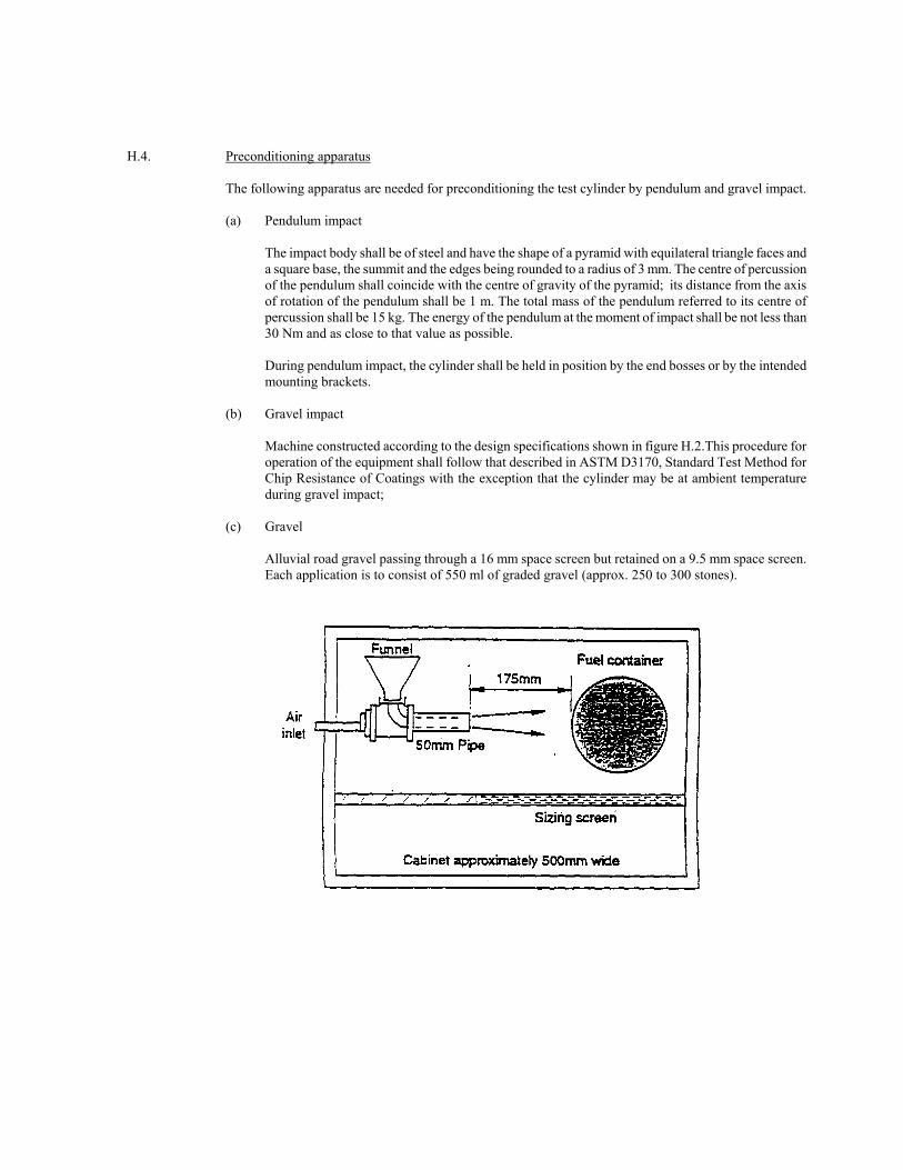
H.4. Preconditioning apparatus The following apparatus are needed for preconditioning the test cylinder by pendulum and gravel impact.
(a) Pendulum impact
The impact body shall be of steel and have the shape of a pyramid with equilateral triangle faces and a square base, the summit and the edges being rounded to a radius of 3 mm. The centre of percussion of the pendulum shall coincide with the centre of gravity of the pyramid; its distance from the axis of rotation of the pendulum shall be 1 m. The total mass of the pendulum referred to its centre of percussion shall be 15 kg. The energy of the pendulum at the moment of impact shall be not less than 30 Nm and as close to that value as possible. During pendulum impact, the cylinder shall be held in position by the end bosses or by the intended mounting brackets.
(b) Gravel impact
Machine constructed according to the design specifications shown in figure H.2.This procedure for operation of the equipment shall follow that described in ASTM D3170, Standard Test Method for Chip Resistance of Coatings with the exception that the cylinder may be at ambient temperature during gravel impact;
(c) Gravel
Alluvial road gravel passing through a 16 mm space screen but retained on a 9.5 mm space screen. Each application is to consist of 550 ml of graded gravel (approx. 250 to 300 stones).

108
Figure H.2 - Gravel impact test
H.5. Exposure environments
(a) Immersion environment
At the specified stage in the test sequence (table 1) the cylinder will be oriented horizontally with the lower third of the cylinder diameter immersed in a simulated acid rain/road salt water solution. The solution will consist of the following compounds:
Deionized water; Sodium chloride: 2.5 percent by weight ± 0.1 percent; Calcium chloride: 2.5 percent by weight ± 0.1 percent; Sulfuric acid: Sufficient to achieve a solution pH of 4.0 ± 0.2;
Solution level and pH are to be adjusted prior to each test step which uses this liquid. The temperature of the bath shall be 21 ± 5 C. During immersion, the unsubmerged section of the cylinder shall be in ambient air.
(b) Other fluid exposure
At the appropriate stage in test sequence (table 1) each marked area is to be exposed to one of five solutions for 30 minutes. The same environment shall be used for each location throughout the test. The solutions are:
Sulfuric acid: 19 percent solution by volume in water; Sodium hydroxide: 25 percent solution by weight in water; Methanol/gasoline: 30/70 percent concentrations; Ammonium nitrate: 28 percent by weight in water; Windshield washer fluid.
When exposed, the test sample will be oriented with the exposure area uppermost. A pad of glass wool one layer thick (approximately 0.5 mm) and trimmed to the appropriate dimensions is to be placed on the exposure area. Using a pipet, apply 5 ml of the test fluid to the exposure area. Remove the gauze pad after pressurization of the cylinder for 30 minutes.
H.6. Test conditions
(a) Pressure cycle
As defined in the test sequence, cylinder shall be hydraulically pressure cycled between not more than 2 MPa and not less than 26 MPa. The total cycle shall be not less than 66 seconds and will include a 60 second minimum hold at 26 MPa. The nominal cycle process will be:

Ramp up from 20 MPa to 26 MPa; Hold at 26 MPa for 60 seconds minimum; Ramp down from 26 MPa to 2 MPa; Total minimum cycle time to be 66 seconds.
(b) Pressure during other fluid exposure
Following application of the other fluids, the cylinder shall be pressured to not less than 26 MPa for a minimum of 30 minutes;
(c) High and low temperature exposure
As defined in the test sequence, the entire cylinder shall be exposed to high or low temperature air in contact with external surface. The low temperature air shall be -40 C or lower and the high temperature air shall be 82 C ± 5 C. For the low temperature exposure, the fluid temperature of type CNG-1 cylinders shall be monitored using a thermocouple installed within the cylinder to ensure it remains at -40 C or lower.
H.7. Test procedure
(a) Preconditioning of the cylinder
Each of the five areas marked for other fluid exposure an the upper section of the cylinder shall be preconditioned by a single impact of the pendulum body summit at their geometric centre. Following impact, the five areas shall be further conditioned by a gravel impact application. The central section of the bottom portion of the cylinder that will be submerged shall be preconditioned by an impact of the pendulum body summit at three locations spaced approximately 150 mm apart. Following impact, the same central section that was impacted shall be further conditioned by a gravel impact application. The cylinder shall be unpressured during preconditioning.
(b) Test sequence and cycles
The sequence of the environment exposure, pressure cycles, and temperature to be used are defined in table 1. The cylinder surface is not to be washed or wiped between stages.
H.8. Acceptable results
Following the above test sequence, the cylinder shall be hydraulically tested to destruction in accordance with the procedure in paragraph A.12. The burst pressure of the cylinder shall be not less than 85 percent of the minimum design burst pressure.
Table H.1 - Test conditions and sequence
Test steps Exposure
environments Number of
pressure cycles Temperature
1 Other fluids -- Ambient 2 Immersion 1875 Ambient 3 Air 1875 High

110
4 Other fluids -- Ambient 5 Immersion 1875 Ambient 6 Air 3750 Low 7 Other fluids -- Ambient 8 Immersion 1875 Ambient 9 Air 1875 High10 Other fluids -- Ambient 11 Immersion 1875 Ambient
Annex 3B
Liquid tanks - Vacuum insulated vessels for the on-board storage of natural gas as a fuel for
automotive vehicles 1. Scope This annex sets out minimum requirements for refillable liquid tanks. The tanks are intended only for the onboard storage of liquid natural gas as a fuel for automotive vehicles to which the tanks are to be fixed. Tanks may be of any austenitic stainless steel material, design or method of manufacture suitable for the specified service conditions. Tanks for LNG covered by this annex are classified in Class 5. Service conditions to which the tanks will be subjected are detailed in paragraph 4. This annex is based upon a working pressure less than 26MPa.Working pressures can be accommodated by adjusting the test pressure by the appropriate factor (ratio) using the following formula: Ptest = 1,3 (WP + 0.1) MPa The service life of the tanks shall be defined by the manufacturer and may vary with applications.
2 Service conditions
2.1 General 2.1.1. Standard service conditions
The standard service conditions specified in this section are provided as a basis for the design, manufacture, inspection, testing, and approval of tanks that are to be mounted permanently on vehicles and used to store natural gas at ambient temperatures for use as a fuel on vehicles.
2.1.2. Use of tanks The service conditions specified are also intended to provide information on how tanks made to this Regulation may safely be used to: (a) manufacturers of tanks; (b) owners of tanks; (c) designers or contractors responsible for the installation of tanks; (d) designers or owners of equipment used to refuel vehicle tanks; (e) suppliers of natural gas; and (f) regulatory authorities who have jurisdiction over tank use.
2.1.3 Periodic requalification
Recommendations for periodic requalification by visual inspection or testing during the service life shall be provided by the tank manufacturer on the basis of use under service conditions specified herein. Each tank shall be visually inspected at least every 120 months after the date of its entry into service on the vehicle (vehicle registration), and at the time of any re-installation, for external damage and deterioration, including under the support straps. The visual inspection shall be performed by a competent agency approved or recognized by the Regulatory Authority, in accordance with the manufacturers specifications: Tanks without label containing mandatory information, or with labels containing mandatory information that are illegible in any way shall be removed from service. If the tank can be positively identified by manufacturer and serial number, a replacement label may be applied, allowing the tank to remain in service.
2.1.3.1 Tanks involved in collisions
Tanks which have been involved in a vehicle collision shall be re-inspected by an agency authorized by the manufacturer, unless otherwise directed by the Authority having jurisdiction. Tanks which have not
112
experienced any impact damage from the collision may be returned to service, otherwise the tank shall be returned to the manufacturer for evaluation.
2.1.3.2 Tanks involved in fires Tanks which have been subject to the action of fire shall be re-inspected by an agency authorized by the manufacturer, or condemned and removed from service.
2.2 Maximum pressure The maximum allowable working pressure (MAWP) shall be defined by the manufacturer and correspond to the nominal primary relief valve setting. The maximum allowable working pressure shall be less than 26MPa.
2.3 Temperature range
Temperature of liquid in tanks may vary from a minimum of -195°C to a maximum of 65°C; 2.4 Gas composition
Hydrogen shall be limited to 2 percent by volume when tanks are manufactured from a steel with an ultimate tensile strength exceeding 950 Mpa
2.5 External surfaces
Tanks are not designed for continuous exposure to mechanical or chemical attack, e.g. leakage from cargo that may be carried on vehicles or severe abrasion damage from road conditions, and shall comply with recognized installation standards. However, tank external surfaces may be inadvertently exposed to: (a) solvents, acids and alkalis, fertilizers; and (b) automotive fluids, including gasoline, hydraulic fluids, glycol and oils.
2.6 Leakage and venting 2.6.3.1 Tanks may be located in enclosed spaces for extended periods of time. Leakage shall be considered in the design. 2.6.3.2 Vehicle LNG tank(s) shall have a design hold time (build without relieving) minimum of 5 days after being filled net
full and at the highest point in the design filling temperature/pressure range. 2.7 Venting management systems…. 3 Design approval 3.1 General
The following information shall be submitted by the tank designer or manufacturer with a request for approval to the Competent Authority: (a) statement of service (paragraph 5.2.) (b) design data (paragraph 5.3.) (c) manufacturing data (paragraph 5.4.) (d) specification sheet (paragraph 5.5.) (e) additional supporting data (paragraph 5.6.)
3.2 Statement of service
The purpose of this statement of service is to guide users and installers of tanks as well as to inform the approving Competent Authority, or their designated representative. The statement of service shall include:
(a) a statement that the tank design is suitable for use in the service conditions defined in paragraph 4 for the service life of the tank; (b) the service life; (c) the minimum in-service test and/or inspection requirements; (d) the pressure relief devices required; (e) support methods, etc., required but not provided; (f) a description of the tank design;

(g) Design hold time. (h) any other information necessary to ensure the safe use and inspection of the tank.
3.3 Design data
3.3.3 Drawings Drawings shall show the following as a minimum:
(a) Title, reference number, date of issue, and revision numbers with dates of issue if applicable; (b) Reference to this Regulation and the tank type; (c) All pressure vessel dimensions complete with tolerances, including details of end closure shapes with minimum thicknesses and of openings; (d) Mass, complete with tolerance, of tanks; (e) Material specifications complete with minimum mechanical and chemical properties or tolerance ranges; (f) Other data such as, minimum test pressure.
3.3.4 Stress analysis report
A stress analysis shall be provided; Acceptable calculation methods include: - finite element; - finite difference; - boundary element; - other established method.
A table summarizing the calculated stresses in the report shall be provided.
3.3.5 Material data A detailed description of the materials and tolerances of the materials properties used in the design shall be provided.
3.3.6 Design qualification test data
The tank material, design, manufacture and examination shall be provided to be adequate for their intended service by meeting the requirements of the tests required for the particular tank design, when tested in accordance with the relevant methods of test detailed in Appendix A to this annex.
The test data shall also document the dimensions, wall thicknesses and weights of each of the test tanks. 4.3.5 Fire protection
The arrangement of pressure relief devices that will protect the tank from sudden rupture when exposed to the fire conditions in paragraph A.5 shall be specified. Test data shall substantiate the effectiveness of the specified fire protection system.
4.3.6 Tank supports
Details of tank supports or support requirements shall be provided in accordance with paragraph 6.11.
4.3.7 Manufacturing data Descriptions of fabrication processes and production tests shall be provided. The following shall be in accordance with EN 1251-2 (2000): - Quality system - Cutting - Cold forming - Hot forming - Manufacturing tolerances - Welding - Non-welded joints
5.3 Specification sheet

114
A summary of the documents providing the information required in paragraph 5.1. shall be listed on a s pecification sheet for each tank design. The title, reference number, revision numbers and dates of original issue and version issues of each document shall be given. All documents shall be signed or initialed by the issuer; The specification sheet shall be given a number, and revision numbers if applicable, that can be used to designate the tank design and shall carry the signature of the engineer responsible for the design. Space shall be provided on the specification sheet for a stamp indicating registration of the design.
5.4 Additional supporting data
Additional data which would support the application, such as the service history of material proposed for use, or the use of a particular tank design in other service conditions, shall be provided where applicable.
5.5 Approval and certification
5.7.1 Inspection and testing Evaluation of conformity is required to be performed in accordance with the provisions of paragraph 9 of this Regulation; In order to ensure that the tanks are in compliance with this international Regulation they shall be subject to inspection in accordance with paragraph 6.10. performed by the Competent Authority.
5.7.2 Test certificate
If the results of prototype testing according to paragraph 6.10. are satisfactory, the Competent Authority shall issue a test certificate. An example of a test certificate is given in Appendix D to this annex.
4 Requirements
6.1 General
The design of tanks shall cover all relevant aspects which are necessary to ensure that every tank produced according to the design is fit for its purpose for the specified service life.
6.2 Design This Regulation does not provide design formulas, but requires the adequacy of the design to be established by appropriate calculations and demonstrated by tanks being capable of consistently passing the materials, design qualification, production tests specified in this Regulation.
6.3 Materials
Materials used shall be suitable for the service conditions specified in paragraph 4. The design shall not have incompatible materials in contact. The design qualification tests for materials are summarized in table 6.1.
The materials of the fuel tank and its accessories shall be compatible, as applicable, with: a) LNG ; b) other media and fluids found in a vehicle environment, such as coolants, brake fluid and battery acid. Materials used at low temperatures shall meet the toughness requirements of ISO 21028-1 (2004). For non-metallic materials, low temperature suitability shall be validated by an experimental method, taking into account the service conditions. The materials used for the outer jacket shall ensure the integrity of the insulation system and shall be made of austenitic stainless steel and their elongation at fracture, at the temperature of liquid nitrogen, shall be at least 12 %. For the inner vessel, if materials other than austenitic stainless steels are used, it shall be ensured that the materials will resist all the in service fatigue loads. A corrosion allowance does not need to be added for the inner vessel. A corrosion allowance does not need to be added on other surfaces, if they are protected against corrosion. For welded vessels, welds shall have properties equivalent to those specified for the parent material for all temperatures that the material may encounter.
6.3.1 Composition The chemical composition of all steels shall be declared and defined at least by:

carbon, manganese, silicon, nickel, chromium, and molybdenum contents, and any other alloying elements intentionally added.
6.3.2 Tensile test The tensile properties of welded steel in the inner vessel shall be tested in accordance with EN 895:1995 and EN 6892-1:2009.
6.3.3 Impact test
The impact properties of welded steel in the inner vessel shall be tested in accordance with EN 1251-2:2000 and EN 10045-1:1990.
6.3.4 Bending test
The bending properties of welded steel in the inner vessel shall be tested in accordance with EN 910:1996.
6.3.5 Weld examination
Radiographic inspection of welded steel in the inner vessel shall be performed in accordance with EN 1251-2:2000 and EN 1435:1997.
6.4 Test pressure The following minimum inner vessel test pressure shall be used in manufacture: Ptest = 1,3 (WP + 0.1) [MPa] Where WP is in Mpa. 6.5 Stress analysis
A stress analysis shall be performed to justify the minimum design wall thicknesses. A stress analysis shall be performed to justify the internal support element design when exposed to the accelerations described in 18.4.4. The stress shall not exceed the minimum ultimate tensile strength of the material when calculated according with a linear stress model. The allowable stress in the internal support elements may not have to be calculated, if it can be demonstrated that the fuel tank supports the accelerations given 18.4.4. without any structure damage to the inner tank or its supports.
6.6 Inspection and testing The manufacturing inspection shall specify programs and procedures for: (a) manufacturing inspection, tests and acceptance criteria; and
(b) periodic in service inspection, tests and acceptance criteria. The interval of visual reinspection of the external vessel surfaces shall be in accordance with paragraph 4.1.4. A guide for manufacturer's instructions for handling, use and inspection is provided in Appendix B to this annex.
6.7 Fire protection
All tanks shall be protected from fire with pressure relief devices. The tank, its materials, pressure relief devices and any added insulation or protective material shall be designed collectively to ensure adequate safety during fire conditions in the test specified in paragraph A.3 ( Annex 3B Appendix A).
Pressure relief devices shall be tested in accordance with paragraph A.5 (Annex 3B Appendix A). 6.8 (Reserved) 6.9 Tank supports
The manufacturer shall specify the means by which tank shall be supported for installation on vehicles. The manufacturer shall also supply installation instructions, including maximum clamping force and torque to not cause unacceptable stress in the tank or damage to the tank surface.

116
6.10 Design qualification tests For the approval of each tank type the material, design, manufacture and examination shall be proved to be adequate
for their intended service by meeting the appropriate requirements of the material qualification tests summarized in table 6.1 of this annex and the tank qualification tests summarized in table 6.2 of this annex, with all tests in accordance with the relevant methods of test as described in Appendix A to this annex. The test tank shall be selected and the tests witnessed by the Competent Authority. If more tanks are subjected to the tests than are required by this annex, all results shall be documented.
6.11 Production examinations and tests Descriptions of production examinations and tests shall be provided. The following shall be in accordance with EN 1251-2 2000:
- Inspection stages - Production control test plates - Non-destructive testing - Rectification - Pressure testing
6.12 Failure to meet test requirements In the event of failure to meet test requirements retesting shall be carried out as follows:
(a) if there is evidence of a fault in carrying out a test, or an error of measurement, a further test shall be performed. If the result of this test is satisfactory, the first test shall be ignored; (b) If the test has been carried out in a satisfactory manner, the cause of test failure shall be identified. If the failure is found during a non-destructive tests, all the identified defective tanks shall be rejected or repaired by an approved method. The non-rejected tanks are then considered as a new batch. All the relevant prototype or batch tests needs to prove the acceptability of the new batch shall be performed again. If one or more tests prove even partially unsatisfactory, all tanks of the batch shall be rejected.
6.13 Change of design
A design change is any change in the selection of structural materials or dimensional change not attributable to normal manufacturing tolerances. Minor design changes shall be permitted to be qualified through a reduced test program. Changes of design specified in table 6.4 shall require design qualification testing as specified in the table.
Table 6.1 Material design qualification tests
Relevant paragraph of this annex Inner vessel Material paragraph
Tensile test 6.3.2
Impact test 6.3.3
Bending test 6.3.4
Weld examination 6.3.5
Table 6.2 Tank design qualification tests Test and annex reference
Test
Bonfire test Annex 3B Appendix A.1
Drop test Annex 3B Appendix A.2
Hold-time test Annex 3B Appendix A.3
Table 6.3 Critical production inspection requirements

Quality inspection
Production control test plates
Non-destructive testing
Pressure testing
Table 6.4 Change of design
Type of test Design change A.1 Bonfire A.2 Drop A.3 Hold-time Diameter > 20 percent X X X Length > 50 percent X X X Working pressure > 20 percent X X X Insulation material / method X X
6.14 Pressure testing
Each finished tank shall be pressure tested in accordance with paragraph A.2 (Annex 3B, Appendix A). 6.15 Tank design qualification tests
6.15.1 General Qualification testing shall be conducted on finished tanks which are representative of normal production and complete with identification marks. Selection, witnessing and documentation of the results shall be in accordance with paragraph 6.11. above.
6.15.2 Bonfire test
Tests shall be conducted in accordance with paragraph A.1 (Annex 3B, Appendix A) and meet the requirements therein.
7 Markings 7.1 On each tank the manufacturer shall provide clear permanent markings not less than 6 mm high. Marking shall
be made either by labels attached by adhesive or plates attached by welds. Adhesive labels and their application shall be in accordance with ISO 7225, or an equivalent Standard. Multiple labels or plates are allowed and should be located such that they are not obscured by mounting brackets. Each tank complying with this annex shall be marked as follows:
(a) Mandatory information: (i) "LNG ONLY"; (ii) Manufacturer’s identification; (iii) Tank identification (applicable part number and a serial number unique for every cylinder); (iv) Working pressure and temperature; (v) ECE Regulation number, along with tank type and certification registration number; (vi) The pressure relief devices and/or valves that are qualified for use with the tank or the means for obtaining information on qualified fire protection systems; (vii) When labels are used, all tanks shall have a unique identification number stamped on an exposed metal surface to permit tracing in the event that the label is destroyed;
(b) Non-mandatory information:
118
On a separate label(s) the following non-mandatory information may be provided: (i) Gas temperature range, e.g. -195 °C to 65 °C; (ii) Nominal water capacity of the tank to two significant numbers. e.g. 120 liters; (iii) Date of original pressure test (month and year). The markings shall be placed in the listed sequence but the specific arrangement may be varied to match the space available. An acceptable example of mandatory information is:
LNG ONLY Manufacturer/Part Number/Serial Number 16 bar/-160 °C ECE R 110 LNG (registration No.) "Use Only Manufacturer-Approved Pressure Relief Device"
8 Preparations for dispatch Prior to dispatch from the manufacturers shop, every tank shall be internally clean. Tanks not immediately closed by the fitting of a valve, and safety devices if applicable, shall have plugs, which prevent entry of moisture and protect threads, fitted to all openings. The manufacturer's statement of service and all necessary information to ensure the proper handling, use and in-service inspection of the tanks shall be supplied to the purchaser. The statement shall be in accordance with Appendix D to this annex.
Annex 3B Appendix A Test methods
A.1 Bonfire test A.1.1 General
The bonfire tests are designed to demonstrate that finished tanks complete with the fire protection system (tank valve, pressure relief devices and/or integral thermal insulation) specified in the design will not burst when tested under the specified fire conditions. Extreme caution must be exercised during fire testing in the event that tank rupture occurs;
A.1.2 Tank set-up
The inner tank shall be at the same temperature as the temperature of the LNG. This requirement shall be deemed met if, during the previous 24 hours, the fuel tank has contained a volume of liquid LNG at least equal to half of the volume of the inner tank.
The fuel tank shall be filled with LNG so that the quantity of LNG measured by the mass measurement system shall be within 10 % of the maximum allowed net quantity that may be contained in the inner tank.
A.1.3 Fire source
The length and the width of the fire shall exceed the plan dimensions of the fuel tank by 0,1 m. ISO 11439 contains directions to produce a suitable fire test. The average temperature shall remain above 590 °C for the duration of the test.
Any fuel may be used for the fire source provided it supplies uniform heat sufficient to maintain the specified test temperatures until the tank is vented. The selection of fuel should take into consideration air pollution concerns. The arrangement of the fire shall be recorded in sufficient detail to ensure the rate of heat input to the tank is reproducible. Any failure or inconsistency of the fire source during a test invalidate the result;
A.1.4 Temperature and pressure measurements
The average temperature of space 10 mm below the fuel tank as measured by two or more thermocouples shall be at least 590 °C. Thermocouple temperatures and the tank pressure shall be recorded at intervals of every 30 seconds or less during the test.
A.1.5 General test requirements
The pressure of the fuel tank at the beginning of the test shall be from 0 MPa to 0,01 MPa at the boiling point of LNG in the inner tank. The lapse of time, from the moment that the average temperature first reaches 590 °C until the opening of the primary pressure relief valve, shall be measured. Once the pressure relief valve opens, the test shall continue until the blow off of the pressure relief valve is complete.
A.1.6 Acceptable results
The Holding time of the fuel tank, which is the lapse of time before the opening of the pressure relief valve, shall not be less than 5 min under an external fire.

120
The fuel tank shall not burst and the pressure inside the inner tank shall not exceed the permissible fault range of the inner tank. The secondary pressure valve shall limit the pressure inside the inner tank to the test pressure in 6.4.
A.2 Drop test
Each family of fuel tanks shall be drop tested to verify tank integrity. Drop tests shall include a 9m drop test of the fuel tank on the most critical area of the tank (other than the piping end) and 3m drop test on the piping end. Tank shall contain an equivalent full weight of liquid nitrogen saturated to one-half the working pressure. There shall be no loss of product for a period of one hour subsequent to the drop test other than relief valve operation and vapor between the filler neck and the secondary check valve in the case of a drop test involving the filler neck. Loss of vacuum, denting of the vessel, piping and piping protection, and damage to the support structure system are acceptable.
The tank shall be subject to a vertical drop test so that it falls on rigid, flat, non-resilient, smooth, and horizontal surface on areas defined below. To do so, the tank is suspended at least height defined above the ground at a point diametrically opposite the impact area, so that the center of gravity is vertically above. Fuel pumps and other tank attachments shall also meet the drop test requirements for the tank and be attached as part of the tests.
A.3 Hold-time test
The tank shall be filled within 10% of maximum allowed net quantity of LNG at manufacturer’s specified highest point in the design filling temperature / pressure range. Hydrostatic pressure shall be recorded every minute for at least 120 hours at ambient temperature of 20±5 deg C. Hydrostatic pressure shall be stable (within 0.1 bar) or increasing throughout duration of test. The combined tank and contents weight shall be measured and verified to be stable (within 1%) throughout duration of test; release of any fluid (bubble tight) during duration of test shall be unacceptable. Acceptable measured hydrostatic pressure at 120 or more hours shall be less than nominal primary relief valve pressure setting of the tank. If hydrostatic pressure is less than nominal primary relief valve pressure setting at 120 hours, the test may be continued until that pressure, and manufacturer’s highest point in the design filling temperature / pressure range may be defined as the hydrostatic pressure recorded 120 hours prior to reaching the nominal primary relief valve pressure setting. The manufacturer may also specify a longer hold-time than 120 hours, or a hold-time (longer than 120 hours) vs. design filling temperature / pressure relationship based on the recorded hydrostatic pressure time history.
Annex 3B – Appendix B REPORT FORMS
NOTE - This appendix is not a mandatory part of this annex.
The following forms should be used:
(1) Description & serial number for vessel (2) Certificates of Conformance, such as relief valves, manual valves, fill fitting, etc. (3) Radiographic test report - weld seams (4) Mechanical test report - joint tensile test, bending tests, impact tests (5) Material test reports - all steel inner vessel components
122
Annex 3BAppendix C
INSTRUCTIONS BY THE TANKS MANUFACTURER REGARDING HANDLING, USE AND INSPECTION OF TANKS
C.1. General
The primary function of this appendix is to provide guidance to the tank purchaser, distributor, installer and user for the safe use of the tank over its intended service life.
C.2. Distribution
The manufacturer shall advise the purchaser that the instructions shall be supplied to all parties involved in the distribution, handling, installation and use of the tank; The document may be reproduced to provide sufficient copies for this purpose, however it shall be marked to provide reference to the tank being delivered;
C.3. Reference to existing codes, standards and regulations
Specific instructions may be stated by reference to national or recognized codes, standards and regulations. C.4. Tank handling
Handling procedures shall be provided to ensure that the tank will not suffer unacceptable damage or contamination during handling.
C.5. Installation
Installation instructions shall be provided to ensure that the tanks will not suffer unacceptable damage during installation and during normal operation over the intended service life.
Where the mounting is specified by the manufacturer, the instructions shall contain where relevant, details such as mounting design, the use of resilient gasket materials, the correct tightening torques and avoidance of direct exposure of the tank to an environment of chemical and mechanical contacts.
Where the mounting is not specified by the manufacturer, the manufacturer shall draw the purchaser's attention to possible long term impacts of the vehicle mounting system, for example: vehicle body movements and tank expansion/contraction in the pressure and temperature conditions of service.
Where applicable, the purchaser's attention shall be drawn to the need to provide installations such that liquids or solids cannot be collected to cause cylinder material damage;
The correct pressure relieve device to be fitted shall be specified.
C.6. Use of tanks
The manufacturer shall draw the purchaser's attention to the intended service conditions specified by this Regulation, in particular the tanks allowable maximum pressures.
C.7. In-service inspection
The manufacturer shall clearly specify the user's obligation to observe the required tank inspection requirements (e.g. reinspection interval, by authorized personnel). This information shall be in agreement with the design approval requirements.

Annex 3B Appendix D REPORT FORM 1
NOTE - This appendix is not a mandatory part of this annex.
The following forms should be used: Form 1: Report of Manufacturer and Certification of Conformance Manufactured by: Located at: Regulatory Registration Number: Manufacturers Mark and Number: Serial Number: from to inclusive Tank description: SIZE: Outside diameter: mm; Length: mm; Marks stamped on shoulder or on labels of the tank are: (a) "LNG only": (b) "DO NOT USE AFTER": (c) "Manufacturer's mark": (d) Serial and part number: (e) Working pressure in MPa: (f) ECE Regulation: (g) Fire protection type: (h) Date of original test (month & year): (i) Tare mass of empty tank (in kg): (j) Authorized Body or Inspectors Mark: (k) Water capacity in L: (l) Test pressure in MPa: (m) Any special instructions: Each tank was made in compliance with all requirements of ECE Regulation No. ... in accordance with the tank description above. Required reports of test results are attached. I hereby certify that all these test results proved satisfactory in every way and are in compliance with the requirements for the type listed above. Comments: Competent Authority: Inspector’s signature: Manufacturer's signature: Place, Date:

124
Annex 4A
PROVISIONS REGARDING THE APPROVAL OF THE CNG AUTOMATIC VALVE, NON-RETURN VALVE, THE PRESSURE RELIEF VALVE, PRESSURE RELIEF DEVICE (TEMPERATURE TRIGGERED), EXCESS FLOW
VALVE, MANUAL VALVE AND THE PRESSURE RELIEF DEVICE (PRESSURE TRIGGERED) 1. The purpose of this annex is to determine the provisions regarding the approval of the automatic valve, the
non-return valve, the pressure relief valve, the pressure relief device and the excess flow valve. 2. The CNG automatic valve 2.1. The materials constituting the CNG automatic valve which are in contact with the CNG when operating,
shall be compatible with the test CNG. In order to verify this compatibility the procedure described in Annex 5D shall be used.
2.2. Operating specifications 2.2.1. The CNG automatic valve shall be so designed as to withstand a pressure of 1.5 times the working
pressure (MPa) without leakage and deformation. 2.2.2. The CNG automatic valve shall be so designed as to be leak-proof at a pressure of 1.5 times the working
pressure (MPa) (see Annex 5B). 2.2.3. The CNG automatic valve, being in the normal position of use specified by the manufacturer, is submitted to
20,000 operations; then it is deactivated. The automatic valve shall remain leak-proof at a pressure of 1.5 times the working pressure (MPa) (see Annex 5B).
2.2.4. The CNG automatic valve shall be so designed to operate at temperatures as specified in Annex 5O. 2.3. The electrical system, if existing, shall be isolated from the body of the automatic valve. Isolation resistance
shall be > 10 MΩ. 2.4. The automatic valve activated by an electric current shall be in a "closed" position when the current is
switched off. 2.5. The automatic valve has to comply with the test procedures for the Class component determined according
to the scheme in Figure 1-1 of paragraph 3 of this Regulation. 3. The non-return valve 3.1. The materials constituting the non-return valve which are in contact with the CNG when operating, shall be
compatible with the test CNG. In order to verify this compatibility the procedure described in Annex 5D shall be used.
3.2. Operating specifications 3.2.1. The non-return valve shall be so designed as to withstand a pressure of 1.5 times the working
pressure (MPa) without leakage and deformation. 3.2.2. The non-return valve shall be so designed as to be leak-proof (external) at a pressure of 1.5 times the
working pressure (MPa) (see Annex 5B). 3.2.3. The non-return valve, being in the normal position of use specified by the manufacturer, is submitted to
20,000 operations; then it is deactivated. The non-return valve shall remain leak-proof (external) at a

pressure of 1.5 times the working pressure (MPa) (see Annex 5B). 3.2.4. The non-return valve shall be so designed to operate at temperatures as specified in Annex 5O. 3.3. The non-return valve has to comply with the test procedures for the Class component determined according
to the scheme in Figure 1-1 of paragraph 3 of this Regulation. 4. The pressure relief valve and pressure relief device 4.1. The materials constituting the pressure relief valve and pressure relief device which are in contact with the
CNG when operating, shall be compatible with the test CNG. In order to verify this compatibility, the procedure described in Annex 5D shall be used.
4.2. Operating specifications 4.2.1. The pressure relief valve and pressure relief device in Class 0 shall be so designed as to withstand a pressure
of 1.5 times the working pressure (MPa) with the outlet closed off. 4.2.2. The pressure relief valve and pressure relief device of Class 1 shall be so designed as to be leak-proof at a
pressure of 1.5 times the working pressure (MPa) with the outlet closed off (see Annex 5B). 4.2.3. The pressure relief valve of Class 1 and Class 2 shall be so designed as to be leak-proof at twice the working
pressure with the outlets closed off. 4.2.4. The pressure relief device shall be so designed to open the fuse at a temperature of 110 ± 10 C. 4.2.5. The pressure relief valve of Class 0 shall be so designed to operate at temperatures from -40 C to 85 C. 4.3. The pressure relief valve and pressure relief device have to comply with the test procedures for the Class
component determined according to the scheme in Figure 1-1 of paragraph 3 of this Regulation. 5. The excess flow valve 5.1. The materials constituting the excess flow valve which are in contact with the CNG when operating, shall be
compatible with the test CNG. In order to verify this compatibility, the procedure described in Annex 5D shall be used.
5.2. Operating specifications 5.2.1. The excess flow valve, if it is not integrated in the tank, shall be so designed as to withstand a pressure of
1.5 times the working pressure (MPa). 5.2.2. The excess flow valve shall be so designed as to be leak-proof at a pressure of 1.5 times the working
pressure (MPa). 5.2.3. The excess flow valve shall be so designed to operate at temperatures as specified in Annex 5O. 5.3. The excess flow valve shall be mounted inside the container. 5.4. The excess flow valve shall be designed with a bypass to allow for equalization of pressures. 5.5. The excess flow valve shall cut-off at a pressure difference over the valve of 650 kPa. 5.6. When the excess flow valve is at cut-off position, the by-pass flow through the valve shall not exceed 0.05

126
normal m3/min at a differential pressure of 10,000 kPa. 5.7. The device have to comply with the test procedures for the Class components, specified in the scheme in
Figure 1-1 of paragraph 3 of this Regulation, except overpressure, external leakage, resistance to dry heat test, ozone ageing.
6. The manual valve 6.1. The manual valve device in Class 0 shall be designed to withstand a pressure of 1.5 times the working
pressure. 6.2. The manual valve device in Class 0 shall be designed to operate at a temperature from -40 °C to 85 °C. 6.3. Manual valve device requirements
One specimen shall be submitted to a fatigue test at a pressure cycling rate not to exceed 4 cycles per minute as follows:
(i) held at 20 °C while pressured for 2,000 cycles between 2 MPa and 26 MPa."
7. Pressure relief device (pressure triggered)
7.1. The materials constituting the PRD (pressure triggered) which are in contact with the CNG when operating, shall be compatible with the test CNG. In order to verify this compatibility, the procedure described in Annex 5D shall be used.
7.2. Operating specifications
7.2.1. The PRD (pressure triggered) of Class 0, shall be so designed to operate at temperatures as specified in the Annex 5O.
7.2.2. The burst pressure shall be 34 MPa ± 10 percent at ambient temperature and at the maximum operating temperature as indicated in Annex 5O.
7.3. The device has to comply with the test procedures for the Class components, specified in the scheme in Figure 1-1 of paragraph 3. of this Regulation, except overpressure, internal leakage and external leakage.
7.4. PRD (pressure triggered) requirements.
7.4.1. Continued operation
7.4.1.1. Test procedure
Cycle the PRD (pressure triggered) according to Table 3, with water between 10 percent and 100 percent of the working pressure, at a maximum cyclic rate of 10 cycles per minute and a temperature of 82 °C ± 2 °C or 57 °C ± 2 °C.

Table 3 — Test temperatures and cycles
Temperature [°C] Cycles82 2,00057 18,000
7.4.1.2. Requirements
7.4.1.2.1. At the completion of the test, the component shall not leak more than 15 cm3/hour when submitted to a gas pressure equal to the maximum working pressure at ambient temperature and at the maximum operating temperature as indicated in Annex 5O.
7.4.1.2.2. At the completion of the test, the PRD (pressure triggered) burst pressure shall be 34 MPa ± 10 percent at ambient temperature and at the maximum operating temperature as indicated in Annex 5O.
7.4.2. Corrosion resistance test
7.4.2.1. Test procedure
The PRD (pressure triggered) shall be subjected to the test procedure described in Annex 5E, except the leakage test.
7.4.2.2. Requirements
7.4.2.2.1. At the completion of the test, the component shall not leak more than 15 cm3/hour when submitted to a gas pressure equal to the maximum working pressure at ambient temperature and at the maximum operating temperature as indicated in Annex 5O.
7.4.2.2.2. At the completion of the test, the PRD (pressure triggered) burst pressure shall be 34 MPa ± 10 percent at ambient temperature and at the maximum operating temperature as indicated in Annex 5O."
128
Annex 4B
PROVISIONS REGARDING THE APPROVAL OF FLEXIBLE FUEL LINES OR HOSES FOR CNG
Scope The purpose of this annex is to determine the provisions regarding the approval of flexible hoses for use with CNG This annex covers three types of flexible hoses: (a) High pressure hoses (Class 0), (b) Medium pressure hoses (Class 1), (c) Low pressure hoses (Class 2)
1. HIGH PRESSURE HOSES, CLASS 0 CLASSIFICATION 1.1. General specifications 1.1.1. The hose shall be so designed as to withstand a maximum working pressure of 1.5 times the working
pressure (MPa). 1.1.2. The hose shall be so designed as to withstand temperatures as specified in Annex 5O. 1.1.3. The inside diameter shall be in compliance with table 1 of Standard ISO 1307. 1.2. Hose construction 1.2.1. The hose must embody a smooth-bore tube and a cover of suitable synthetic material, reinforced with
one or more interlayer(s). 1.2.2. The reinforcing interlayer(s) has (have) to be protected by a cover against corrosion. If for the reinforcing interlayer(s) corrosion-resistant-material is used (i.e. stainless-steel) a cover is not
required. 1.2.3. The lining and the cover must be smooth and free from pores, holes and strange elements. An intentionally provided puncture in the cover shall not be considered as an imperfection. 1.2.4. The cover has to be intentionally perforated to avoid the forming of bubbles. 1.2.5. When the cover is punctured and the interlayer is made of a non-corrosion-resistant material, the
interlayer has to be protected against corrosion. 1.3. Specifications and tests for the lining 1.3.1. Tensile strength and elongation for rubber material and for thermoplastic elastomers (TPE) 1.3.1.1. Tensile strength and elongation at break according to ISO 37. Tensile strength not less than 20 MPa
and elongation at break not less than 250 percent. 1.3.1.2. Resistance to n-pentane according to ISO 1817 with the following conditions:
(a) medium: n-pentane

(b) temperature: 23C (tolerance according to ISO 1817) (c) immersion period: 72 hours
Requirements: (a) maximum change in volume 20 percent (b) maximum change in tensile strength 25 percent (c) maximum change in elongation at break 30 percent
After storage in air with a temperature of 40 C for a period of 48 hours the mass compared to the original value may not decrease more than 5 percent.
1.3.1.3. Resistance to ageing according to ISO 188 with the following conditions:
(a) temperature: 115 °C (test temperature = maximum operating temperature minus 10 °C). (b) exposure period: 24 and 336 hours.
After ageing the specimens have to be conditioned at 23 °C and 50 percent relative humidity for at least 21 days prior to carrying out the tensile test according to paragraph 1.3.1.1. Requirements: (a) maximum change in tensile strength 35 percent after 336 hours ageing compared to the tensile
strength of the 24 hours aged material. (b) maximum change in elongation at break 25 percent after 336 hours ageing compared to the
elongation at break of the 24 hours aged material. 1.3.2. Tensile strength and elongation specific for thermoplastic material. 1.3.2.1. Tensile strength and elongation at break according to ISO 527-2 with the following conditions:
(a) specimen type: type 1 BA. (b) tensile speed: 20 mm/min.
The material has to be conditioned for at least 21 days at 23 °C and 50 percent relative humidity prior to testing.
Requirements:
(a) tensile strength not less than 20 MPa. (b) elongation at break not less than 100 percent.
1.3.2.2. Resistance to n-pentane according to ISO 1817 with the following conditions:
(a) medium: n-pentane. (b) temperature: 23 °C (tolerance according to ISO 1817). (c) immersion period: 72 hours. Requirements: (a) maximum change in volume 2 percent. (b) maximum change in tensile strength 10 percent. (c) maximum change in elongation at break 10 percent.

130
After storage in air with a temperature of 40 °C for a period of 48 hours the mass compared to the original value may not decrease more than 5 percent.
1.3.2.3. Resistance to ageing according to ISO 188 with the following conditions:
(a) temperature: 115 °C (test temperature = maximum operating temperature minus 10 °C). (b) exposure period: 24 and 336 hours.
After ageing the specimens have to be conditioned at 23 °C and 50 percent relative humidity for at least 21 days prior to carrying out the tensile test according to paragraph 1.3.2.1. Requirements:
(a) maximum change in tensile strength 35 percent after 336 hours ageing compared to the tensile
strength of the 24 hours aged material. (b) maximum change in elongation at break 25 percent after 336 hours ageing compared to the
elongation at break of the 24 hours aged material. 1.4. Specifications and test-method for the cover 1.4.1. Tensile strength and elongation for rubber material and for thermoplastic elastomers (TPE) 1.4.1.1. Tensile strength and elongation at break according to ISO 37. Tensile strength not less than 10 MPa
and elongation at break not less than 250 percent. 1.4.1.2. Resistance to n-hexane according to ISO 1817 with the following conditions:
(a) medium: n-hexane (b) temperature: 23 C (tolerance acc.to ISO 1817) (c) immersion period: 72 hours Requirements: (a) maximum change in volume 30 percent (b) maximum change in tensile strength 35 percent (c) maximum change in elongation at break 35 percent
1.4.1.3. Resistance to ageing according to ISO 188 with the following conditions:
(a) temperature: 115 °C (test temperature = maximum operating temperature minus 10 °C). (b) exposure period: 24 and 336 hours. After ageing the specimens have to be conditioned at 23 °C and 50 percent relative humidity for at least 21 days prior to carrying out the tensile test according to paragraph 1.4.1.1. Requirements:
(a) maximum change in tensile strength 35 percent after 336 hours ageing compared to the tensile
strength of the 24 hours aged material. (b) maximum change in elongation at break 25 percent after 336 hours ageing compared to the
elongation at break of the 24 hours aged material. 1.4.2. Tensile strength and elongation specific for thermoplastic material.

1.4.2.1. Tensile strength and elongation at break according to ISO 527-2 with the following conditions:
(a) specimen type: type 1 BA. (b) tensile speed: 20 mm/min. The material has to be conditioned for at least 21 days at 23 °C and 50 percent relative humidity prior to testing. Requirements: (a) tensile strength not less than 20 MPa. (b) elongation at break not less than 100 percent.
1.4.2.2. Resistance to n-hexane according to ISO 1817 with the following conditions: (a) medium: n-hexane. (b) temperature: 23 °C (tolerance according to ISO 1817). (c) immersion period: 72 hours. Requirements: (a) maximum change in volume 2 percent. (b) maximum change in tensile strength 10 percent. (c) maximum change in elongation at break 10 percent.
After storage in air with a temperature of 40 °C for a period of 48 hours the mass compared to the original value may not decrease more than 5 percent.
1.4.2.3. Resistance to ageing according to ISO 188 with the following conditions:
(a) temperature: 115 °C (test temperature = maximum operating temperature minus 10 °C). (b) exposure period: 24 and 336 hours. After ageing the specimens have to be conditioned at 23 °C and 50 percent relative humidity for at least 21 days prior to carrying out the tensile test according to paragraph 1.4.2.1. Requirements: (a) maximum change in tensile strength 20 percent after 336 hours ageing compared to the tensile
strength of the 24 hours aged material. (b) maximum change in elongation at break 50 percent after 336 hours ageing compared to the
elongation at break of the 24 hours aged material.
1.4.3. Resistance to ozone 1.4.3.1. The test has to be performed in compliance with Standard ISO 1431/1. 1.4.3.2. The test-pieces, which have to be stretched to an elongation of 20 percent shall have to be exposed to
air of 40 C with an ozone-concentration of 50 parts per hundred million during 120 hours. 1.4.3.3. No cracking of the test pieces is allowed. 1.5. Specifications for uncoupled hose

132
1.5.1. Gas-tightness (permeability) 1.5.1.1. A hose at a free length of 1 m has to be connected to a container filled with liquid propane, having a
temperature of 23 ± 2 C. 1.5.1.2. The test has to be carried out in compliance with the method described in Standard ISO 4080. 1.5.1.3. The leakage through the wall of the hose shall not exceed 95 cm3 per meter of hose per 24 h. 1.5.2. Resistance at low temperature 1.5.2.1. The test has to be carried out in compliance with the method described in Standard ISO 4672-1978,
method B. 1.5.2.2. Test temperature: -40 °C ± 3 °C or -20 °C ± 3 °C, if applicable. 1.5.2.3. No cracking or rupture is allowed. 1.5.3. Bending test 1.5.3.1. An empty hose, at a length of approximately 3.5 m must be able to withstand 3,000 times the hereafter
prescribed alternating-bending-test without breaking. After the test the hose must be capable of withstanding the test-pressure as mentioned in paragraph 1.5.4.2. The test shall be performed on both new hose and after ageing according to ISO 188 as prescribed in paragraph 1.4.2.3. and subsequently to ISO 1817 as prescribed in paragraph 1.4.2.2.
1.5.3.2.
Figure 1 (example only)
Hose inside diameter (mm)
Bending radius ([mm)
(Figure 1)
Distance between centres (mm) (Figure 1)
Vertical b
Horizontal a
up to 13 102 241 102 13 to 16 153 356 153
from 16 to 20 178 419 178 1.5.3.3. The testing-machine (Figure 1) shall consist of a steel frame, provided with two wooden wheels, with a
rim-width of c.a. 130 mm. The circumference of the wheels must be grooved for the guidance of the hose. The radius of the wheels, measured to the bottom of the groove, must be as indicated in paragraph 1.5.3.2.

The longitudinal median planes of both wheels must be in the same vertical plane and the distance between the wheel-centers must be in accordance with paragraph 1.5.3.2. Each wheel must be able to rotate freely round its pivot-centre. A propulsion-mechanism pulls the hose over the wheels at a speed of four complete motions per minute.
1.5.3.4. The hose shall be S-shape-like installed over the wheels (see Figure 1). The end, that runs over the upper wheel shall be furnished with a sufficient mass as to achieve a
complete snuggling of the hose against the wheels. The part that runs over the lower wheel is attached to the propulsion-mechanism.
The mechanism must be so adjusted, that the hose travels a total distance of 1.2 m in both directions. 1.5.4. Hydraulic-test-pressure and appointment of the minimum burst-pressure 1.5.4.1. The test has to be carried out in compliance with the method described in Standard ISO 1402. 1.5.4.2. The test-pressure of 1.5 times the working pressure (MPa) shall be applied during 10 minutes, without
any leakage. 1.5.4.3. The burst pressure shall not be less than 45 MPa. 1.6. Couplings 1.6.1. The couplings shall be made from steel or brass and the surface must be corrosion-resistant. 1.6.2. The couplings must be of the crimp-fitting type. 1.6.2.1. The swivel-nut must be provided with U.N.F.-thread. 1.6.2.2. The sealing cone of swivel-nut type must be of the type with a half vertical angle of 45°. 1.6.2.3. The couplings can be made as swivel-nut type or as quick-connector type. 1.6.2.4. It shall be impossible to disconnect the quick-connector type without specific measures or the use of
dedicated tools. 1.7. Assembly of hose and couplings 1.7.1. The construction of the couplings must be such, that it is not necessary to peel the cover unless the
reinforcement of the hose consists of corrosion-resistant material. 1.7.2. The hose assembly has to be subjected to an impulse test in compliance with Standard ISO 1436. 1.7.2.1. The test has to be completed with circulating oil having a temperature of 93 C, and a minimum
pressure of 26 MPa. 1.7.2.2. The hose has to be subjected to 150,000 impulses. 1.7.2.3. After the impulse-test the hose has to withstand the test-pressure as mentioned in paragraph 1.5.4.2.

134
1.7.3. Gas-tightness 1.7.3.1. The hose assembly (hose with couplings) has to withstand during five minutes a gas pressure of 1.5
times the working pressure (MPa) without any leakage. 1.8. Markings 1.8.1. Every hose must bear, at intervals of not greater than 0.5 m, the following clearly legible and indelible
identification markings consisting of characters, figures or symbols. 1.8.1.1. The trade name or mark of the manufacturer. 1.8.1.2. The year and month of fabrication. 1.8.1.3. The size and type-marking. 1.8.1.4. The identification-marking "CNG Class 0". 1.8.2. Every coupling shall bear the trade name or mark of the assembling manufacturer. 2. MEDIUM PRESSURE HOSES, CLASS 1 CLASSIFICATION 2.1. General specifications 2.1.1. The hose shall be so designed as to withstand a maximum working pressure of 3 MPa. 2.1.2. The hose shall be so designed as to withstand temperatures as specified in Annex 5O. 2.1.3. The inside diameter shall be in compliance with table 1 of Standard ISO 1307. 2.2. Hose construction 2.2.1. The hose must embody a smooth-bore tube and a cover of suitable synthetic material, reinforced with
one or more interlayer(s). 2.2.2. The reinforcing interlayer(s) has (have) to be protected by a cover against corrosion. If for the reinforcing interlayer(s) corrosion-resistant-material is used (i.e. stainless-steel) a cover is not
required. 2.2.3. The lining and the cover must be smooth and free from pores, holes and strange elements. An intentionally provided puncture in the cover shall not be considered as an imperfection. 2.3. Specifications and tests for the lining 2.3.1. Tensile strength and elongation for rubber material and for thermoplastic elastomers (TPE) 2.3.1.1. Tensile strength and elongation at break according to ISO 37. Tensile strength not less than 10 MPa
and elongation at break not less than 250 percent. 2.3.1.2. Resistance to n-pentane according to ISO 1817 with the following conditions:
(a) medium: n-pentane (b) temperature: 23 C (tolerance acc. to ISO 1817)
(c) immersion period: 72 hours Requirements: (a) maximum change in volume 20 percent (b) maximum change in tensile strength 25 percent (c) maximum change in elongation at break 30 percent
After storage in air with a temperature of 40 C for a period of 48 hours the mass compared to the original value may not decrease more than 5 percent.
2.3.1.3. Resistance to ageing according to ISO 188 with the following conditions:
(a) temperature: 115 °C (test temperature = maximum operating temperature minus 10 °C). (b) exposure period: 24 and 336 hours.
After ageing the specimens have to be conditioned at 23 °C and 50 percent relative humidity for at least 21 days prior to carrying out the tensile test according to paragraph 2.3.1.1.
Requirements:
(a) maximum change in tensile strength 35 percent after 336 hours ageing compared to the tensile
strength of the 24 hours aged material. (b) maximum change in elongation at break 25 percent after 336 hours ageing compared to the
elongation at break of the 24 hours aged material.
2.3.2. Tensile strength and elongation specific for thermoplastic material.
2.3.2.1. Tensile strength and elongation at break according to ISO 527-2 with the following conditions:
(a) specimen type: type 1 BA. (b) tensile speed: 20 mm/min. The material has to be conditioned for at least 21 days at 23 °C and 50 percent relative humidity prior to testing. Requirements: (a) tensile strength not less than 20 MPa. (b) elongation at break not less than 100 percent.
2.3.2.2. Resistance to n-pentane according to ISO 1817 with the following conditions:
(a) medium: n-pentane. (b) temperature: 23 °C (tolerance according to ISO 1817). (c) immersion period: 72 hours. Requirements: (a) maximum change in volume 2 percent. (b) maximum change in tensile strength 10 percent. (c) maximum change in elongation at break 10 percent.
After storage in air with a temperature of 40 °C for a period of 48 hours the mass compared to the original value may not decrease more than 5 percent.

136
2.3.2.3. Resistance to ageing according to ISO 188 with the following conditions:
(a) temperature: 115 °C (test temperature = maximum operating temperature minus 10 °C). (b) exposure period: 24 and 336 hours.
After ageing the specimens have to be conditioned at 23 °C and 50 percent relative humidity for at least 21 days prior to carrying out the tensile test according to paragraph 2.3.2.1.
Requirements:
(a) maximum change in tensile strength 35 percent after 336 hours ageing compared to the tensile
strength of the 24 hours aged material. (b) maximum change in elongation at break 25 percent after 336 hours ageing compared to the
elongation at break of the 24 hours aged material. 2.4. Specifications and test-method for the cover 2.4.1. Tensile strength and elongation for rubber material and for thermoplastic elastomers (TPE) 2.4.1.1. Tensile strength and elongation at break according to ISO 37. Tensile strength not less than 10 MPa
and elongation at break not less than 250 percent. 2.4.1.2. Resistance to n-hexane according to ISO 1817 with the following conditions:
(a) medium: n-hexane (b) temperature: 23 C (tolerance acc. to ISO 1817) (c) immersion period: 72 hours Requirements: (a) maximum change in volume 30 percent (b) maximum change in tensile strength 35 percent (c) maximum change in elongation at break 35 percent
2.4.1.3. Resistance to ageing according to ISO 188 with the following conditions:
(a) temperature: 115 °C (test temperature = maximum operating temperature minus 10 °C) (b) exposure period: 24 and 336 hours After ageing the specimens have to be conditioned at 23 °C and 50 percent relative humidity for at least 21 days prior to carrying out the tensile test according to paragraph 2.4.1.1. Requirements: (a) maximum change in tensile strength 35 percent after 336 hours ageing compared to the tensile
strength of the 24 hours aged material. (b) maximum change in elongation at break 25 percent after 336 hours ageing compared to the
elongation at break of the 24 hours aged material. 2.4.2. Tensile strength and elongation specific for thermoplastic material. 2.4.2.1. Tensile strength and elongation at break according to ISO 527-2 with the following conditions:

(a) specimen type: type 1 BA. (b) tensile speed: 20 mm/min. The material has to be conditioned for at least 21 days at 23 °C and 50 percent relative humidity prior to testing. Requirements: (a) tensile strength not less than 20 MPa. (a) elongation at break not less than 100 percent.
2.4.2.2. Resistance to n-hexane according to ISO 1817 with the following conditions: (a) medium: n-hexane. (b) temperature: 23 °C (tolerance according to ISO 1817). (c) immersion period: 72 hours. Requirements: (a) maximum change in volume 2 percent. (b) maximum change in tensile strength 10 percent. (c) maximum change in elongation at break 10 percent.
After storage in air with a temperature of 40 °C for a period of 48 hours the mass compared to the original value may not decrease more than 5 percent.
2.4.2.3. Resistance to ageing according to ISO 188 with the following conditions:
(a) temperature: 115 °C (test temperature = maximum operating temperature minus 10 °C). (b) exposure period: 24 and 336 hours. After ageing the specimens have to be conditioned at 23 °C and 50 percent relative humidity for at least 21 days prior to carrying out the tensile test according to paragraph 2.4.2.1. Requirements: (a) maximum change in tensile strength 20 percent after 336 hours ageing compared to the tensile
strength of the 24 hours aged material. (b) maximum change in elongation at break 50 percent after 336 hours ageing compared to the
elongation at break of the 24 hours aged material. 2.4.3. Resistance to ozone 2.4.3.1. The test has to be performed in compliance with Standard ISO 1431/1. 2.4.3.2. The test-pieces, which have to be stretched to an elongation of 20 percent shall have to be exposed to
air of 40 C with an ozone-concentration of 50 parts per hundred million during 120 hours. 2.4.3.3. No cracking of the test pieces is allowed. 2.5. Specifications for uncoupled hose 2.5.1. Gas-tightness (permeability)

138
2.5.1.1. A hose at a free length of 1 m has to be connected to a container filled with liquid propane, having a
temperature of 23 ± 2 C. 2.5.1.2. The test has to be carried out in compliance with the method described in Standard ISO 4080. 2.5.1.3. The leakage through the wall of the hose shall not exceed 95 cm3 per meter of hose per 24 h. 2.5.2. Resistance at low temperature 2.5.2.1. The test has to be carried out in compliance with the method described in Standard ISO 4672-1978,
method B. 2.5.2.2. Test temperature: -40 °C ± 3 °C or -20 °C ± 3 °C, if applicable." 2.5.2.3. No cracking or rupture is allowed. 2.5.3. Bending test 2.5.3.1. An empty hose, at a length of approximately 3.5 m must be able to withstand 3,000 times the hereafter
prescribed alternating-bending-test without breaking. After the test the hose must be capable of withstanding the test-pressure as mentioned in paragraph 2.5.4.2. The test shall be performed on both new hose and after ageing according to ISO 188 as prescribed in paragraph 2.4.2.3. and subsequently to ISO 1817 as prescribed in paragraph 2.4.2.2.
2.5.3.2.
Figure 2 (example only)
Hose inside diameter [mm]
Bending radius [mm]
(Figure 2)
Distance between centres [mm] (Figure 2)
Vertical b
Horizontal a
up to 13 102 241 102 13 to 16 153 356 153
from 16 to 20 178 419 178 2.5.3.3. The testing-machine (Figure 2) shall consist of a steel frame, provided with two wooden wheels, with a
rim-width of c.a. 130 mm.

The circumference of the wheels must be grooved for the guidance of the hose. The radius of the wheels, measured to the bottom of the groove, must be as indicated in paragraph 2.5.3.2. The longitudinal median planes of both wheels must be in the same vertical plane and the distance between the wheel-centers must be in accordance with paragraph 2.5.3.2. Each wheel must be able to rotate freely round its pivot-centre. A propulsion-mechanism pulls the hose over the wheels at a speed of four complete motions per minute.
2.5.3.4. The hose shall be S-shape-like installed over the wheels (see Figure 2).
The end, that runs over the upper wheel shall be furnished with a sufficient mass as to achieve a complete snuggling of the hose against the wheels. The part that runs over the lower wheel is attached to the propulsion mechanism. The mechanism must be so adjusted, that the hose travels a total distance of 1.2 m in both directions.
2.5.4. Hydraulic-test-pressure 2.5.4.1. The test has to be carried out in compliance with the method described in Standard ISO 1402. 2.5.4.2. The test-pressure of 3 MPa shall be applied during 10 minutes, without any leakage. 2.6. Couplings 2.6.1. If a coupling is mounted on the hose the following conditions have to be met: 2.6.2. The couplings shall be made from steel or brass and the surface must be corrosion-resistant. 2.6.3. The couplings must be of the crimp-fitting type. 2.6.4. The couplings can be made as swivel-nut type or as quick-connector type. 2.6.5. It shall be impossible to disconnect the quick-connector type without specific measures or the use of
dedicated tools. 2.7. Assembly of hose and couplings 2.7.1. The construction of the couplings must be such, that it is not necessary to peel the cover unless the
reinforcement of the hose consists of corrosion-resistant material. 2.7.2. The hose assembly has to be subjected to an impulse test in compliance with Standard ISO 1436. 2.7.2.1. The test has to be completed with circulating oil having a temperature of 93 C, and a minimum
pressure of 1.5 times the maximum working pressure. 2.7.2.2. The hose has to be subjected to 150,000 impulses. 2.7.2.3. After the impulse-test the hose has to withstand the test-pressure as mentioned in paragraph 2.5.4.2.

140
2.7.3. Gas-tightness 2.7.3.1. The hose assembly (hose with couplings) has to withstand during five minutes a gas pressure of 3 MPa
without any leakage. 2.8. Markings 2.8.1. Every hose must bear, at intervals of not greater than 0.5 m, the following clearly legible and indelible
identification markings consisting of characters, figures or symbols. 2.8.1.1. The trade name or mark of the manufacturer. 2.8.1.2. The year and month of fabrication. 2.8.1.3. The size and type marking. 2.8.1.4. The identification-marking "CNG Class 1". 2.8.2. Every coupling shall bear the trade name or mark of the assembling manufacturer. 3. LOW PRESSURE HOSES, CLASS 2 CLASSIFICATION 3.1. General specifications 3.1.1. The hose shall be so designed as to withstand a maximum working pressure of 450 kPa. 3.1.2. The hose shall be so designed as to withstand temperatures as specified in Annex 5O. 3.1.3. The inside diameter shall be in compliance with table 1 of Standard ISO 1307. 3.2. (Not allocated) 3.3. Specifications and tests for the lining 3.3.1. Tensile strength and elongation for rubber material and for thermoplastic elastomers (TPE) 3.3.1.1. Tensile strength and elongation at break according to ISO 37 Tensile strength not less than 10 MPa and elongation at break not less than 250 percent. 3.3.1.2. Resistance to n-pentane according to ISO 1817 with the following conditions:
(a) medium: n-pentane (b) temperature: 23 C (tolerance acc. to ISO 1817) (c) immersion period: 72 hours Requirements: (a) maximum change in volume 20 percent (b) maximum change in tensile strength 25 percent (c) maximum change in elongation at break 30 percent
After storage in air with a temperature of 40 C for a period of 48 hours the mass compared to the original value may not decrease more than 5 percent.
3.3.1.3. Resistance to ageing according to ISO 188 with the following conditions:
(a) temperature: 115 °C (test temperature = maximum operating temperature minus 10 ° C). (b) exposure period: 24 and 336 hours. After ageing the specimens have to be conditioned at 23 °C and 50 percent relative humidity for at least 21 days prior to carrying out the tensile test according to paragraph 3.3.1.1. Requirements: (a) maximum change in tensile strength 35 percent after 336 hours ageing compared to the tensile
strength of the 24 hours aged material. (b) maximum change in elongation at break 25 percent after 336 hours ageing compared to the
elongation at break of the 24 hours aged material. 3.3.2. Tensile strength and elongation specific for thermoplastic material. 3.3.2.1. Tensile strength and elongation at break according to ISO 527-2 with the following conditions:
(a) specimen type: type 1 BA. (b) tensile speed: 20 mm/min. The material has to be conditioned for at least 21 days at 23 °C and 50 percent relative humidity prior to testing. Requirements: (a) tensile strength not less than 20 MPa. (b) elongation at break not less than 100 percent.
3.3.2.2. Resistance to n-pentane according to ISO 1817 with the following conditions:
(a) medium: n-pentane. (b) temperature: 23 °C (tolerance according to ISO 1817). (c) immersion period: 72 hours. Requirements: (a) maximum change in volume 2 percent. (b) maximum change in tensile strength 10 percent. (c) maximum change in elongation at break 10 percent.
After storage in air with a temperature of 40 °C for a period of 48 hours the mass compared to the original value may not decrease more than 5 percent.
3.3.2.3. Resistance to ageing according to ISO 188 with the following conditions:
(a) temperature: 115 °C (test temperature = maximum operating temperature minus 10 ° C). (b) exposure period: 24 and 336 hours.
After ageing the specimens have to be conditioned at 23 °C and 50 percent relative humidity for at least 21 days prior to carrying out the tensile test according to paragraph 3.3.2.1.
142
Requirements:
(a) maximum change in tensile strength 35 percent after 336 hours ageing compared to the tensile strength of the 24 hours aged material.
(b) maximum change in elongation at break 25 percent after 336 hours ageing compared to the elongation at break of the 24 hours aged material.
3.4. Specifications and test-method for the cover 3.4.1. Tensile strength and elongation for rubber material and for thermoplastic elastomers (TPE) 3.4.1.1. Tensile strength and elongation at break according to ISO 37 Tensile strength not less than 10 MPa and elongation at break not less than 250 percent. 3.4.1.2. Resistance to n-hexane according to ISO 1817 with the following conditions:
(a) medium: n-hexane (b) temperature: 23 C (tolerance acc. to ISO 1817) (c) immersion period: 72 hours Requirements: (a) maximum change in volume 30 percent (b) maximum change in tensile strength 35 percent (c) maximum change in elongation at break 35 percent
3.4.1.3. Resistance to ageing according to ISO 188 with the following conditions:
(a) temperature: 115 °C (test temperature = maximum operating temperature minus 10 ° C). (b) exposure period: 24 and 336 hours.
After ageing the specimens have to be conditioned at 23 °C and 50 percent relative humidity for at least 21 days prior to carrying out the tensile test according to paragraph 3.4.1.1.
Requirements:
(a) maximum change in tensile strength 35 percent after 336 hours ageing compared to the tensile
strength of the 24 hours aged material. (b) maximum change in elongation at break 25 percent after 336 hours ageing compared to the
elongation at break of the 24 hours aged material. 3.4.2. Tensile strength and elongation specific for thermoplastic material. 3.4.2.1. Tensile strength and elongation at break according to ISO 527-2 with the following conditions:
(a) specimen type: type 1 BA. (b) tensile speed: 20 mm/min.
The material has to be conditioned for at least 21 days at 23 °C and 50 percent relative humidity prior to testing. Requirements:

(a) tensile strength not less than 20 MPa. (b) elongation at break not less than 100 percent.
3.4.2.2. Resistance to n-hexane according to ISO 1817 with the following conditions:
(a) medium: n-hexane. (b) temperature: 23 °C (tolerance according to ISO 1817). (c) immersion period: 72 hours.
Requirements:
(a) maximum change in volume 2 percent. (b) maximum change in tensile strength 10 percent. (c) maximum change in elongation at break 10 percent.
After storage in air with a temperature of 40 °C for a period of 48 hours the mass compared to the original value may not decrease more than 5 percent.
3.4.2.3. Resistance to ageing according to ISO 188 with the following conditions:
(a) temperature: 115 °C (test temperature = maximum operating temperature minus 10 °C). (b) exposure period: 24 and 336 hours.
After ageing the specimens have to be conditioned at 23 °C and 50 percent relative humidity for at least 21 days prior to carrying out the tensile test according to paragraph 3.4.2.1. Requirements:
(a) maximum change in tensile strength 20 percent after 336 hours ageing compared to the tensile
strength of the 24 hours aged material. (b) maximum change in elongation at break 50 percent after 336 hours ageing compared to the
elongation at break of the 24 hours aged material. 3.4.3. Resistance to ozone 3.4.3.1. The test has to be performed in compliance with Standard ISO 1431/1. 3.4.3.2. The test-pieces, which have to be stretched to an elongation of 20 percent shall have to be exposed to
air of 40 C and a relative humidity of 50 percent ± 10 percent with an ozone concentration of 50 parts per hundred million during 120 hours.
3.4.3.3. No cracking of the test pieces is allowed. 3.5. Specifications for uncoupled hose 3.5.1. Gas-tightness (permeability) 3.5.1.1. A hose at a free length of 1 m has to be connected to a container filled with liquid propane, having a
temperature of 23 ± 2 C. 3.5.1.2. The test has to be carried out in compliance with the method described in Standard ISO 4080. 3.5.1.3. The leakage through the wall of the hose shall not exceed 95 cm3 per meter of hose per 24 h.

144
3.5.2. Resistance at low temperature 3.5.2.1. The test has to be carried out in compliance with the method described in Standard ISO 4672, method
B. 3.5.2.2. Test temperature: -40 °C ± 3 °C or -20 °C ± 3 °C, if applicable. 3.5.2.3. No cracking or rupture is allowed. 3.5.3. Resistance at high temperature 3.5.3.1. A piece of hose, pressurized at 450 kPa, with a minimal length of 0.5 m must be put in an oven at a
temperature of 120 C ± 2 C during 24 hours. The test shall be performed on both new hose and after ageing according to ISO 188 as prescribed in paragraph 3.4.2.3. and subsequently to ISO 1817 as prescribed in paragraph 3.4.2.2.
3.5.3.2. The leakage through the wall of the hose shall not exceed 95 cm3 per meter of hose per 24 h. 3.5.3.3. After the test the hose shall withstand the test pressure of 50 kPa during 10 minutes. The leakage
through the wall of the hose shall not exceed 95 cm3 per meter of hose per 24 h. 3.5.4. Bending test 3.5.4.1. An empty hose, at a length of approximately 3.5 m must be able to withstand 3,000 times the hereafter
prescribed alternating-bending-test without breaking. 3.5.4.2. (a = 102 mm; b= 241 mm)
Figure 3 (example only)
The testing machine (Figure 3) shall consist of a steel frame, provided with two wooden wheels, with a rim width of approx. 130 mm. The circumference of the wheels must be grooved for the guidance of the hose. The radius of the wheels, measured to the bottom of the groove, must be 102 mm. The longitudinal median planes of both wheels must be in the same vertical plane. The distance between the wheel-centres must be vertical 241 mm and horizontal 102 mm. Each wheel must be able to rotate freely round its pivot-centre.
A propulsion-mechanism pulls the hose over the wheels at a speed of four complete motions per minute.
3.5.4.3. The hose shall be S-shape-like installed over the wheels (see Figure 3).
The end, that runs over the upper wheel, shall be furnished with a sufficient mass as to achieve a complete snuggling of the hose against the wheels. The part that runs over the lower wheel is attached to the propulsion mechanism. The mechanism must be so adjusted, that the hose travels a total distance of 1.2 m in both directions.
3.6. Markings 3.6.1. Every hose must bear, at intervals of not greater than 0.5 m, the following clearly legible and indelible
identification markings consisting of characters, figures or symbols. 3.6.1.1. The trade name or mark of the manufacturer. 3.6.1.2. The year and month of fabrication. 3.6.1.3. The size and type marking. 3.6.1.4. The identification marking "CNG Class 2". 3.6.2. Every coupling shall bear the trade name or mark of the assembling manufacturer.

Annex 4C
PROVISIONS REGARDING THE APPROVAL OF THE CNG FILTER 1. The purpose of this annex is to determine the provisions regarding the approval of the CNG filter. 2. Operating conditions 2.1. The CNG filter shall be so designed to operate at temperatures as specified in Annex 5O. 2.2. CNG filter shall be Classified with regard to the maximum working pressure (see figure 1-1 paragraph
3 of this Regulation): 2.2.1. Class 0: The CNG filter shall be so designed to withstand a pressure of 1.5 times the working
pressure (MPa). 2.2.2. Class 1 and Class 2: The CNG filter shall be so designed to withstand a pressure twice the working
pressure. 2.2.3. Class 3: the CNG filter shall be so designed to withstand a pressure twice the relief pressure of the
pressure relief valve on which it is subject. 2.3. The materials used in the CNG filter which are in contact with CNG when operating, shall be
compatible with this gas (see Annex 5D). 2.4. The component has to comply with the test procedures for Class components according to the scheme
in Figure 1-1 of paragraph 3 of this Regulation.

Annex 4D
PROVISIONS REGARDING THE APPROVAL OF THE CNG PRESSURE REGULATOR 1. The purpose of this annex is to determine the provisions regarding the approval of the pressure
regulator. 2. CNG Pressure regulator 2.1. The material constituting the regulator which is in contact with the compressed natural gas when
operating shall be compatible with the test CNG. In order to verify this compatibility, the procedure in Annex 5D shall be used.
2.2. The materials constituting the regulator which are in contact with the heat exchange medium of the
regulator when operating, shall be compatible with that fluid. 2.3. The component shall comply with the test procedures provided for in Class 0 for the parts subject to
high pressure and Class 1, 2, 3 and 4 for the parts subject to medium and low pressure. 2.4. Durability test (continued operation) of CNG pressure regulator: The regulator shall be able to withstand 50,000 cycles without any failure when tested according to the
following procedure. Where the stages of pressure regulation are separate, the service pressure in sub-paragraphs (a) to (f) is considered to be the working pressure of the upstream stage.
(a) Recycle the regulator for 95 percent of the total number of cycles at room temperature and at the service pressure. Each cycle shall consist of flow until stable outlet pressure has been obtained, after which the gas flow shall be shut off by a downstream valve within 1 s, until the downstream lock-up pressure has stabilized. Stabilized outlet pressures are defined as set pressure ±15 percent for at least 5 s.
(b) Cycle the inlet pressure of the regulator for 1 percent of the total number of cycles at room temperature from 100 percent to 50 percent of the service pressure. The duration of each cycle shall be no less than 10 s.
(c) Repeat the cycling procedure of (a) at 120 °C at the service pressure for 1 percent of the total number of cycles.
(d) Repeat the cycling procedure of (b) at 120 °C at the service pressure for 1 percent of the total number of cycles.
(e) Repeat the cycling procedure of (a) at -40 °C or -20 °C as applicable and 50 percent of service pressure for 1 percent of the total number of cycles.
(f) Repeat the cycling procedure of (b) at -40 °C or -20 °C as applicable and 50 percent of service pressure for 1 percent of the total number of cycles.
(g) At the completion of all tests indicated in sub-paragraphs (a), (b), (c), (d), (e) and (f), the regulator shall be leak proof (see Annex 5B) at the temperatures of -40 °C or -20 °C, as applicable, and at the room temperature and at the temperature of +120 °C."
3. Classification and test pressures 3.1 The part of the pressure regulator which is in contact with the pressure of the container is regarded as
Class 0. 3.1.1. The Class 0 part of the pressure regulator shall be leak-proof (see Annex 5B) at a pressure up to 1.5
times the working pressure (MPa) with the outlet(s) of that part closed off. 3.1.2. The Class 0 part of the pressure regulator shall withstand a pressure up to 1.5 times the working
pressure (MPa).

148
3.1.3. The Class 1 and Class 2 part of theCNG pressure regulator shall be leak-proof (see Annex 5B) at a
pressure up to twice the working pressure. 3.1.4. The Class 1 and Class 2 part of the CNG pressure regulator shall withstand a pressure up to twice the
working pressure. 3.1.5. The Class 3 part of theCNG pressure regulator shall withstand a pressure up to twice the relief pressure
of the pressure relief valve, on which it is subject. 3.2. The pressure regulator shall be so designed to operate at temperatures as specified in Annex 5O.
Annex 4E
PROVISIONS REGARDING THE APPROVAL OF THE CNG PRESSURE AND TEMPERATURE SENSORS 1. The purpose of this annex is to determine the provisions regarding the approval of the CNG pressure
and temperature sensors. 2. CNG Pressure and temperature sensors 2.1. The material constituting the pressure and temperature sensors which is in contact with the CNG when
operating shall be compatible with the test CNG. In order to verify this compatibility, the procedure in Annex 5D shall be used.
2.2. The CNG pressure and temperature sensors are classified in a Class according to the scheme 1-1 in
paragraph 3 of this Regulation. 3. Classification and test pressures 3.1 The part of the CNG pressure and temperature sensors which is in contact with the pressure of the
container is regarded as Class 0. 3.1.1. The Class 0 part of the CNG pressure and temperature sensors shall be leak-proof at a pressure up to
1.5 times the working pressure (MPa) (see Annex 5B). 3.1.2. The Class 0 part of theCNG pressure and temperature sensors shall withstand a pressure up to 1.5
times the working pressure (MPa). 3.1.3. The Class 1 and Class 2 part of the CNG pressure and temperature sensors shall be leak-proof at a
pressure up to twice the working pressure (see Annex 5B). 3.1.4. The Class 1 and Class 2 part of the CNG pressure and temperature sensors shall withstand a pressure
up to twice the working pressure. 3.1.5. The Class 3 part of the CNG pressure and temperature sensors shall withstand a pressure up to twice
the relief pressure of the pressure relief valve, on which it is subject. 3.2. TheCNG pressure and temperature sensors shall be so designed to operate at temperatures as specified
in Annex 5O. 3.3. The electrical system, if existing, shall be isolated from the body of the pressure and temperature
sensors. Isolation resistance shall be > 10 MΩ.
Annex 4F
PROVISIONS REGARDING THE APPROVAL OF THE CNG FILLING UNIT (Receptacle) 1. Scope The purpose of this annex is to determine the provisions regarding the approval of the CNG filling
unit. 2. The CNG filling unit 2.1. TheCNG filling unit shall comply with the requirements laid down in paragraph 3. and shall have the
dimensions of paragraph 4.. 2.2. CNG Filling units designed in accordance with ISO 14469-1 first edition 2004-11-01 1/ or ISO 14469-
2:2007 2/ and meeting all the requirements therein are deemed to fulfil the requirements of paragraphs 3. and 4. of this annex.
3. The CNG filling unit test procedures 3.1. The CNG filling unit shall be conform to the requirements of Class 0 and follow the test procedures in
Annex 5 with the following specific requirements. 3.2. The material constituting the CNG filling unit which is in contact with the CNG when the device is in
service shall be compatible with the CNG. In order to verify this compatibility, the procedure of Annex 5D shall be used.
3.3. The CNG filling unit shall be free from leakage at a pressure of 1.5 times the working pressure (MPa)
(see Annex 5B). 3.4. The CNG filling unit shall withstand a pressure of 33 MPa. 3.5. The CNg filling unit shall be so designed as to operate at temperatures as specified in Annex 5O. 3.6. The CNG filling unit shall withstand a number of 10,000 cycles in the durability test specified in
Annex 5L. 4. CNG Filling unit dimensions 4.1. Figure 1 shows the dimensions of the filling unit for vehicles of categories M1 and N1. 3/ 4.2 Figure 2 shows the dimensions of the filling unit for vehicles of categories M2, M3, N2 and N3. 3/
1/ Road Vehicles Compressed Natural Gas (CNG) refuelling connector - part 1: 20 MPa (200 bar) connector.
2/ Road Vehicles Compressed Natural Gas (CNG) refuelling connector – part 2: 20 Mpa (200 bar) connector size 2.
3/ As defined in Annex 7 to the Consolidated Resolution on the Construction of Vehicles (R.E.3) (document TRANS/WP.29/78/Rev.1/Amend.2 as last amended by Amend.4).

Fig. 1: 20 MPa filling unit (receptacle) for M1 and N1 vehicles
1 Sealing surface equivalent to No. 110 O-ring of dimensions: Dimensions in millimetres 9.19 mm 0.127 mm ID Surface roughness Ra 3.2 m 2.62 mm 0.076 mm width Sealing surface finish: 0.8 m to 0.05 m Material hardness: 75 Rockwell (HRB 75) minimum a Minimum length of the receptacle which is clear of provisions for attachement of receptacle or protective caps.
This area shall be kept free of all components.
Key

E/ECE/324 E/ECE/TRANS/505 Rev.2/Add.109/Rev.1
Regulation No. 110 page 152 Annex 4F
152
“Figure 2 20 MPa Filling unit Size 2 (receptacle) for M2, M3, N2 and N3 vehicles

Annex 4G
PROVISIONS REGARDING THE APPROVAL OF CNG GAS FLOW ADJUSTER AND GAS/AIR MIXER OR GAS INJECTOR
1. The purpose of this annex is to determine the provisions regarding the approval of the gas flow
adjuster and gas/air mixer or gas injector. 2. Gas/air mixer or gas injector 2.1. The material constituting the gas/air mixer or gas injector which is in contact with CNG shall be
compatible with the CNG. In order to verify this compatibility, the procedure specified in Annex 5D shall be used.
2.2. The gas/air mixer or gas injector shall conform to the requirements of Class 1 or 2 components,
according to their Classification. 2.3. Test pressures 2.3.1. The gas/air mixer or gas injector of Class 2 shall withstand a pressure twice the working pressure. 2.3.1.1. The gas/air mixer or gas injector of Class 2 shall be free from leakage at a pressure twice the working
pressure. 2.3.2. The gas/air mixer or gas injector of Class 1 and Class 2 shall be so designed to operate at temperatures
as specified in Annex 5O. 2.4. Electrical operated components containing CNG shall comply with the following:
(a) They shall have a separate ground connection; (b) The electrical system of the component shall be isolated from the body; (c) The gas injector shall be in closed position when the electric current is switched off.
3. Gas flow adjuster 3.1. The material constituting the gas flow adjuster which is in contact with the CNG shall be compatible
with the CNG. In order to verify this compatibility the procedure specified in Annex 5D has to be used.
3.2. The gas flow adjuster shall conform to requirements of Class 1 or 2 components, according to their
Classification. 3.3. Test pressures 3.3.1. The gas flow adjuster of Class 2 shall withstand a pressure twice the working pressure. 3.3.1.1. The gas flow adjuster of Class 2 shall be free from leakage at a pressure twice the working pressure. 3.3.2. The gas flow adjuster of Class 1 and Class 2 shall be so designed to operate at temperatures as
specified in Annex 5O. 3.4. Electrical operated components containing CNG shall comply with the following:

154
(a) They shall have a separate ground connection; (b) The electrical system of the component shall be isolated from the body.

Annex 4H
PROVISIONS REGARDING THE APPROVAL OF THE ELECTRONIC CONTROL UNIT 1. The purpose of this annex is to determine the provisions regarding the approval of the electronic control
unit. 2. Electronic control unit 2.1. The electronic control unit can be any device which controls the CNG/LNG demand of the engine and
establishes the cut-off of the automatic valve in case of a broken fuel supply pipe or in case of stalling of the engine, or during a crash.
2.2. The switching off delay of the automatic valve after stalling of the engine may not be more than 5
seconds. 2.3. The device may be equipped with an automatic ignition advance timing adjuster integrated in the
electronic module or separated. 2.4. The device may be integrated with dummy injectors to permit a correct functioning of the gasoline
electronic control unit during CNG/LNG operation. 2.5. The electronic control unit shall be so designed to operate at temperatures as specified in Annex 5O.
156
Annex 4I
Provisions regarding the approval of LNG heat exchanger – vaporizer
1. The purpose of this annex is to determine the provisions regarding the approval of the LNG heat exchanger - Vaporizer.
2. LNG Heat exchanger – vaporizer 2.1 The LNG heat exchanger –vaporizer can be any device made for vaporizing the cryogenic liquid fuel and
deliver it as gas to the engine with gas temperature between -40°C and +105°C 2.2 The material constituting the LNG heat exchanger - vaporizer which is in contact with the CNG when
operating shall be compatible with the test CNG. In order to verify this compatibility, the procedure in Annex 5D shall be used.
2.3 The part of the LNG heat exchanger - vaporizer which is in contact with the tank is regarded as Class 5. 2.4 The LNG heat exchanger – vaporizer shall be so designed as to withstand a pressure of 1.5 times the working
pressure (MPa) without leakage and deformation.
2.5 The LNG heat exchanger – vaporizer shall be so designed as to be leak-proof (external) at a pressure of 1.5
times the working pressure (MPa) (see Annex 5B). 2.6 The LNG heat exchanger – vaporizer shall be so designed to operate at temperatures as specified in Annex
5O.
2.7 The LNG heat exchanger – vaporizer has to comply with the test procedures for the Class 5. 2.8 The LNG heat exchanger – vaporizer has to comply with the water jacket freezing test. Fill the part of the
heat exchanger-vaporizer which normally contains an antifreeze solution, with water to normal capacity and expose it at -40°C for 24h. Attach 1 m sections of coolant hose to the coolant inlet and outlet of the heat exchanger – vaporizer. Following the freezing conditioning, conduct an external leakage test according to Annex 5B at room temperature. A separate sample may be used for this test.

E/ECE/324E/ECE/TRANS/505 Rev.2/Add.109/Rev.1
Regulation No. 110 page 157 Annex 5
Annex 4J
Provisions regarding the approval of LNG filling receptacle
Scope 1. The purpose of this annex is to determine the provisions regarding the approval of the LNG filling receptacle.
2. LNG filling receptacle
2.1 The LNG filling receptacle shall comply with the requirements laid down in paragraph 3. 3 The LNG filling receptacle test procedures
3.1 the LNG filling receptacle shall conform to the requirements of Class 5 and follow the test procedures in Annex 5 with the following specific requirements. 3.2 The non metallic material constituting the LNG filling receptacle shall be compatible with LNG. In order to verify this compatibility, the procedure of Annex 5D, 5F and 5G shall be used. 3.3. The LNG filling receptacle shall be free from leakage at a pressure of 1.5 times the working pressure (MPa) (see annex 5B) 3.4. The LNG filling receptacle shall be designed as to operate at temperatures as specified in Annex 5O. 3.5The filling unit shall withstand 7.000 cycles in the durability in Annex 5L,as follows: 3.5.1. Low temperature cycling
The component shall be connected for 96% percent of the total cycles at cryogenic temperature and at rated service pressure. The source can be liquid or gaseous nitrogen (or LNG) at or below the temperature corresponding to LNG rated service pressure. (see table in Annex 5O). Flow should be established, and then shut off. During the off cycle the down stream pressure of the test fixture should be allowed to decay to 50 percent of the test pressure. On completion of the cycles,, the components shall comply with the leakage test of annex 5B.at cryogenic temperature. It is allowed to interrupt this part of the test at 20 percent intervals for leakage testing 3.5.2 Room temperature cycling The component shall be operated through 2 percent of the total cycles as above at the appropriate room temperature specified at rated service pressure. The component shall comply with the leakage test of the annex 5B at the room temperature at the completion of the room temperature cycles. 3.5.3 High temperature cycling The component shall be operated through 2 percent of the total cycles as above at the appropriate maximum temperature specified at rated service pressure. The component shall comply with the leakage test of the annex 5B at the room temperature at the completion of the room temperature cycles. Following cycling and leakage re-test the component shall be capable of remove of the filling nozzle without spilling more than 30cm3 LNG. 3.6 The LNG filling receptacle shall be made out of non sparking material and should comply with the no igniting evaluation tests described in ISO14469-1:2004. 3.7 The electrical resistance of the connected LNG filling receptacle and nozzle shall be not be greater than 10 Ω either in the pressurized and un-pressurized state. Test shall be conducted prior to and after the endurance test.

158
Annex 4K
Provisions regarding the approval of LNG pressure control regulator Scope
1. The purpose of this annex is to determine the provisions regarding the approval of the LNG pressure control regulator. 2 LNG pressure control regulator 2.1 The material constituting the regulator which is in contact with the LNG when operating shall be compatible with the test LNG. In order to verify this compatibility, the procedure in Annex 5D shall be used. 2.2 The LNG pressure control regulator shall comply with the tests mentioned for class 5. 3 Classification and test pressures 3.1 The pressure regulator that is in contact with the pressure of the LNG is regarded as Class 5. 3.1.1 The pressure control regulator shall be leak proof (see Annex 5B) with the outlet (s) of that part closed off. 3.2. The pressure regulator shall be so designed to operate at temperatures as specified in Annex 5O. 3.3 Durability test 3.3.1 Perform the durability test mentioned in Annex 5L with the following exceptions: - The number of cycles is 7.000 - The component shall be connected to a source of pressurized cryogenic fluid. - The component shall be operated to 2 percent of the total cycles at the appropriate minimum temperature (-40°C) connected to a source of pressurized cryogenic fluid.

E/ECE/324E/ECE/TRANS/505 Rev.2/Add.109/Rev.1
Regulation No. 110 page 159 Annex 5
Annex 4L Provisions regarding the approval of LNG pressure and/or temperature sensor
Scope
1. The purpose of this annex is to determine the provisions regarding the approval of the LNG pressure and/or temperature sensor.
2. LNG pressure and temperature sensors 2.1 The LNG pressure and temperature sensors are classified in class 5 according to the scheme 1-1 in paragraph 3
3 The LNG pressure and/or temperature sensor test procedures 3.1 The LNG pressure and/or temperature sensor test procedures shall be conform to the requirements of Class 5
and follow the test procedures in Annex 5 with the following specific requirements. 3.2 Insulation resistance test
This test is designed to check for a potential failure of the insulation between the LNG pressure and/or temperature sensor connection pins and the housing. Apply 1 000 V d.c. between one of the connector pins and the housing of the LNG pressure and/or temperature sensor for at least 2s. The minimum allowable resistance shall be >10MΩ.
3.3 The material constituting the LNG pressure and temperature sensors witch is in contact with the LNG when
operating shall be compatible with the test LNG. In order to verify this compatibility, the procedure in Annex 5D shall be used.
3.4 The LNG pressure and/or temperature sensor shall be so designed as to operate at temperatures as specified in
Annex 5O.
3.5. The Class 5 part of the LNG pressure and temperature sensors shall withstand a pressure up to 1.5 times the working pressure (MPa), at the temperature corresponding to rated service pressure from the table in annex 5O, at room temperature and at the maximum temperature from Annex 5O.

160
Annex 4M Provisions regarding the approval of the Natural gas detector
Scope
1.The purpose of this annex is to determine the provisions regarding the approval of the Natural gas detector. 2 Natural gas detector 2.1 the material constituting the natural gas detector which is in contact with the natural gas when operating shall be compatible with the test gas. In order to verify this compatibility, the procedure in Annex 5D shall be used. 3. The natural gas detector test procedures 3.1 The natural gas detector shall be so designed as to operate at temperatures as specified in Annex 5O. 3.2 Insulation resistance test This test is designed to check for a potential failure of the insulation between the connection pins and the housing of the natural gas detector. Apply 1 000 V d.c. between one of the connector pins and the housing of the natural gas detector for at least 2s. The minimum allowable resistance shall be 10MΩ. 3.3 The natural gas detector shall comply with relevant electromagnetic compatibility (EMC) requirements according to Regulation No. 10, 03 series of amendments or equivalent.

E/ECE/324E/ECE/TRANS/505 Rev.2/Add.109/Rev.1
Regulation No. 110 page 161 Annex 5
Annex 4N Provisions regarding the approval of the automatic valve, check valve, pressure relief valve, excess
flow valve, manual valve and non-return valve for LNG applications. 1 The purpose of this annex is to determine the provisions regarding the approval of the automatic valve, the check valve, the pressure relief valve and the excess flow valve only for LNG applications. 2 the LNG automatic valve. 2.1 operating specifications 2.2.1 The LNG automatic valve shall be so designed as to withstand a pressure of 1.5 times the working pressure (MPa) without leakage or deformation.(See Annex 5A). 2.2.2 The LNG automatic valve shall be so designed as to be leak-proof at a pressure of 1.5 times the working pressure (Mpa) (see Annex 5B) 2.2.3 The LNG automatic valve, being in the normal position of use specified by the manufacturer, is submitted to 7,000 operations; then it is deactivated. The automatic valve shall remain leak-proof according to Annex 5B and 5C at a pressure of 1.5 times the working pressure. This test is performed for 96% of its cycles at cryogenic temperatures. 2% at ambient temperature and 2% at high temperature according to the table in Annex 5O. 2.2.4 The LNG automatic valve shall be so designed to operate at temperatures as specified in Annex 5O. 2.2.5 The insulation resistance test. This test is designed to check for a potential failure of the insulation between the two-pin coil assembly and the LNG automatic valve casing. Apply 1 000 V d.c. between one of the connector pins and the housing of the automatic valve for at least 2s. The minimum allowable resistance shall be 10MΩ. 3 the LNG check valve 3.1. The materials constituting the LNG check valve which are in contact with the LNG when operating,
shall be compatible with the test LNG. In order to verify this compatibility the procedure described in Annex 5D shall be used.
3.2. Operating specifications 3.2.1. The LNG check valve shall be so designed as to withstand a pressure of 1.5 times the working
pressure (MPa) without leakage and deformation at cryogenic temperature. 3.2.2. The LNG check valve shall be so designed as to be leak-proof (external) at a pressure of 1.5 times the
working pressure (MPa) (see Annex 5B) with the temperatures given in Annex 5O. 3.2.3. The LNG check valve, being in the normal position of use specified by the manufacturer, is submitted to
7,000 operations at cryogenic temperature (see Annex 5O); then it is deactivated. The check valve shall remain leak-proof (external) at a pressure of 1.5 times the working pressure (MPa) (see Annex 5B).
3.2.4. The LNG check valve shall be so designed to operate at temperatures as specified in Annex 5O. 3.3. The LNG check valve has to comply with the test procedures for the Class 5 component

162
4. The LNG pressure relief valve 4.1. The materials constituting the pressure relief valve which are in contact with the LNG when operating,
shall be compatible with the test LNG. In order to verify this compatibility, the procedure described in Annex 5D shall be used.
4.2. Operating specifications 4.2.1. The LNG pressure relief valve in Class 5 shall be so designed as to withstand a pressure of 1.5 times the
working pressure (MPa) at cryogenic temperature with the outlet closed off. 4.2.2. The pressure relief valve and pressure relief device of Class 5 shall be so designed as to be leak-proof at
a pressure of 1.5 times the working pressure (MPa) with the outlet closed off (see Annex 5B). 4.3. The LNG pressure relief valve has to comply with the test procedures for the Class 5 component. 5. The LNG excess flow valve 5.1. The materials constituting the LNG excess flow valve that are in contact with the LNG when operating,
shall be compatible with the test LNG. In order to verify this compatibility, the procedure described in Annex 5D shall be used.
5.2. Operating specifications 5.2.1. The LNG excess flow valve, if it is not mounted inside the tank, shall be so designed as to withstand a pressure of 1.5 times the working pressure (MPa) at cryogenic temperature. 5.2.2. The LNG excess flow valve shall, if it is not mounted inside the tank, be so designed as to be external
leak-proof (Annex 5B) at a pressure of 1.5 times the working pressure (MPa). 5.2.3. The LNG excess flow valve shall be so designed to operate at temperatures as specified in Annex 5O. 5.3. The LNG excess flow valve shall be designed with a bypass (internal leak) to allow for
equalization of pressures. 5.4. An excess flow valve shall operate at not more than 10 percent above, nor less than 20 percent
below the rated closing flow capacity specified by the manufacturer. 5.4.1. Three samples of each size and style of valve are to be subjected to these tests. The LNG valve
intended for use only with liquid is to be tested with water. Except as indicated in paragraph 5.4.3., separate tests are to be run with each sample installed in vertical, horizontal and inverted positions.
5.4.2 The test with water is to be conducted using a liquid flow meter (or equivalent) installed in a piping
system having sufficient pressure to provide the required flow. The system is to include an inlet piezometer or pipe at least one pipe size larger than the valve to be tested, with a flow control valve connected between the flow meter and piezometer. A hose or hydrostatic relief valve, or both, may be used to reduce the effect of the pressure shock when the excess flow valve closes.
5.4.3 A valve intended for installation in one position only may be tested only in that position. 5.5 When the LNG excess flow valve is at cut-off position, the by-pass flow through the valve shall not
exceed an airflow rate declared by the manufacturer in cm3/min at service pressure.

E/ECE/324E/ECE/TRANS/505 Rev.2/Add.109/Rev.1
Regulation No. 110 page 163 Annex 5
5.6. The device shall comply with the test procedures for the Class 5 components. 6. The LNG manual valve 6.1. The LNG manual valve device in Class 5 shall be designed to withstand a pressure of 1.5 times the
working pressure at cryogenic temperature. 6.2. The LNG manual valve device in Class 5 shall be designed to operate at a temperature from -162 °C
to 85 °C. 6.3 LNG manual valve device requirements
One specimen shall be submitted to a fatigue test at a pressure-cycling rate not to exceed 4 cycles a minute as follows: (i) Held at -162°C or lower while pressured for 100 cycles between 0 and WP. The maximum torque on the valve shall than comply with 2 times the force mentioned in table 5.3 in Annex 5L. After the test the LNG manual valve shall comply with the external leak test in Annex 5B. If during this test icing occurs, the LNG manual valve may be de-iced and dried.
6.4 The materials constituting the LNG manual valve which are in contact with the LNG when operating,
shall be compatible with the test LNG. In order to verify this compatibility, the procedure described in Annex 5D shall be used.
6.5 The LNG non-return valve has to comply with the test procedures for the Class 5 component

164
Annex 4O LNG fuel pump
1 Definition: see paragraph 4. (number) of this Regulation. 2. Component classification Class 5. 3. Applicable test procedures: 3.1. LNG fuel pump mounted inside the container: Low temperature test Annex 5P LNG compatibility Annex 5D Resistance to dry heat Annex 5F Ozone ageing Annex 5G 3.2. LNG fuel pump mounted outside the container: Overpressure or strength Annex 5A External leakage Annex 5B LNG compatibility Annex 5D Corrosion resistance Annex 5E Resistance to dry heat Annex 5F Ozone ageing Annex 5G Temperature cycle Annex 5H Vibration resistance Annex 5N Low temperature test Annex 5P
4 LNG fuel pump requirements.
4.1 The LNG fuel pump shall be constructed of materials suitable for the temperature and pressure conditions that might be encountered.
4.2 The LNG fuel pump shall be constructed in such a manner as to avoid LNG trapping. 4.3 Means shall be provided for the LNG present in the pump at engine shut-off, to be safely processed
without pressure increase above maximum safe working pressure. 4.4 The LNG fuel pump shall be provided with pressure control device to maintain the pressure within
the operating pressure range. 4.4.1 The limitation of the power supplied by the actuating mechanism can be accepted in lieu of pressure
control device. 4.4.2 An electronic control system can be accepted in lieu of pressure control device. 4.4.3 The pressure control device, is not allowed the vent natural gas to atmosphere during normal
function. 4.5 LNG fuel pump shall be provided with pressure relief device to limit the pressure to the maximum
safe working pressure of the pump. 4.5.1 The fuel system pressure relief device is acceptable in lieu of pump pressure relief device if by
relieving system pressure it relieves the pump pressure.

E/ECE/324E/ECE/TRANS/505 Rev.2/Add.109/Rev.1
Regulation No. 110 page 165 Annex 5
4.6 The LNG fuel pump is allowed to function before the engine is started to produce required pressure in the fuel system. This function shall be achieved without delivering fuel to the engine if the engine is not running.
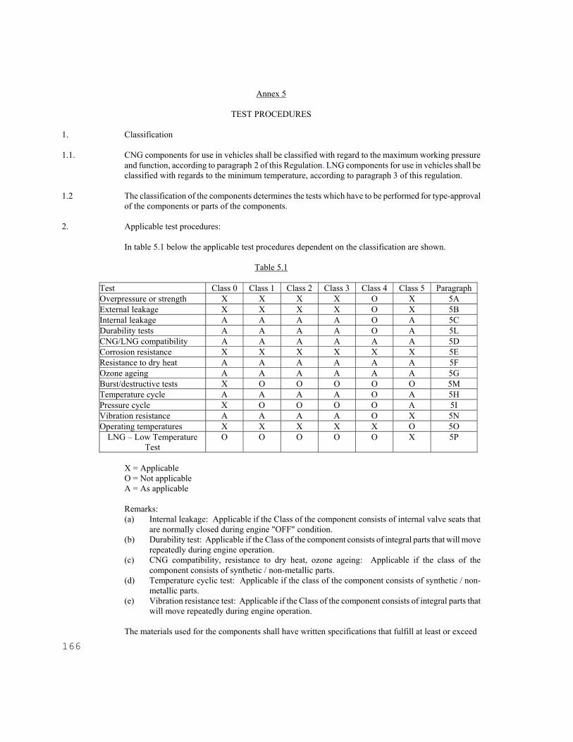
166
Annex 5
TEST PROCEDURES 1. Classification 1.1. CNG components for use in vehicles shall be classified with regard to the maximum working pressure
and function, according to paragraph 2 of this Regulation. LNG components for use in vehicles shall be classified with regards to the minimum temperature, according to paragraph 3 of this regulation.
1.2 The classification of the components determines the tests which have to be performed for type-approval
of the components or parts of the components. 2. Applicable test procedures: In table 5.1 below the applicable test procedures dependent on the classification are shown.
Table 5.1
Test Class 0 Class 1 Class 2 Class 3 Class 4 Class 5 Paragraph Overpressure or strength X X X X O X 5A External leakage X X X X O X 5B Internal leakage A A A A O A 5C Durability tests A A A A O A 5L CNG/LNG compatibility A A A A A A 5D Corrosion resistance X X X X X X 5E Resistance to dry heat A A A A A A 5F Ozone ageing A A A A A A 5G Burst/destructive tests X O O O O O 5M Temperature cycle A A A A O A 5H Pressure cycle X O O O O A 5I Vibration resistance A A A A O X 5N Operating temperatures X X X X X O 5O
LNG – Low Temperature Test
O O O O O X 5P
X = Applicable O = Not applicable A = As applicable Remarks: (a) Internal leakage: Applicable if the Class of the component consists of internal valve seats that
are normally closed during engine "OFF" condition. (b) Durability test: Applicable if the Class of the component consists of integral parts that will move
repeatedly during engine operation. (c) CNG compatibility, resistance to dry heat, ozone ageing: Applicable if the class of the
component consists of synthetic / non-metallic parts. (d) Temperature cyclic test: Applicable if the class of the component consists of synthetic / non-
metallic parts. (e) Vibration resistance test: Applicable if the Class of the component consists of integral parts that
will move repeatedly during engine operation.
The materials used for the components shall have written specifications that fulfill at least or exceed

E/ECE/324E/ECE/TRANS/505 Rev.2/Add.109/Rev.1
Regulation No. 110 page 167 Annex 5
the (test) requirements laid down in this annex with respect to:
(a) temperature (b) pressure (c) CNG/LNG compatibility (d) durability
3. General requirements 3.1. Leakage tests shall have to be conducted with pressurized gas like air or nitrogen for CNG. For LNG
cryogenic fluid shall be used. 3.2. Water or another fluid may be used to obtain the required pressure for the hydrostatic strength test. 3.3. The test period for leakage- and hydrostatic strength-tests shall be not less than 3 minutes.
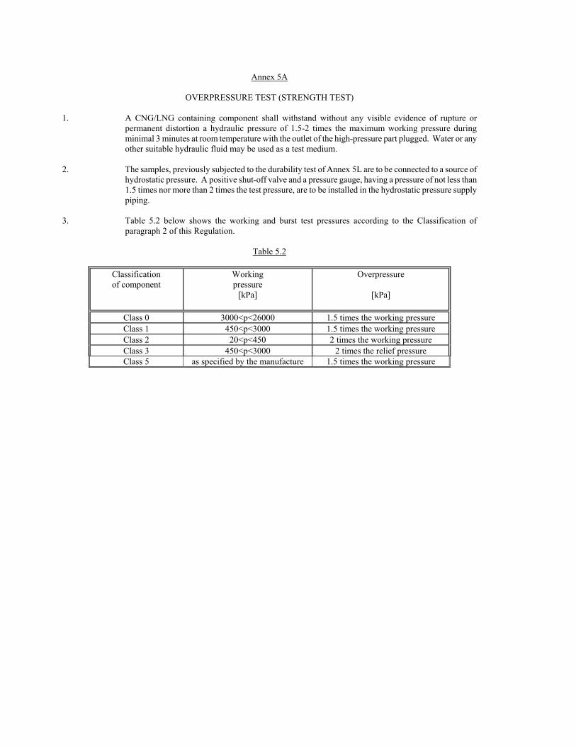
Annex 5A
OVERPRESSURE TEST (STRENGTH TEST) 1. A CNG/LNG containing component shall withstand without any visible evidence of rupture or
permanent distortion a hydraulic pressure of 1.5-2 times the maximum working pressure during minimal 3 minutes at room temperature with the outlet of the high-pressure part plugged. Water or any other suitable hydraulic fluid may be used as a test medium.
2. The samples, previously subjected to the durability test of Annex 5L are to be connected to a source of
hydrostatic pressure. A positive shut-off valve and a pressure gauge, having a pressure of not less than 1.5 times nor more than 2 times the test pressure, are to be installed in the hydrostatic pressure supply piping.
3. Table 5.2 below shows the working and burst test pressures according to the Classification of
paragraph 2 of this Regulation.
Table 5.2
Classification of component
Working pressure
[kPa]
Overpressure
[kPa]
Class 0 3000<p<26000 1.5 times the working pressure Class 1 450<p<3000 1.5 times the working pressure Class 2 20<p<450 2 times the working pressure Class 3 450<p<3000 2 times the relief pressure Class 5 as specified by the manufacture 1.5 times the working pressure

Annex 5B
EXTERNAL LEAKAGE TEST 1. A component shall be free from leakage through stem or body seals or other joints, and shall not show
evidence of porosity in casting when tested as described in paragraphs 2. and 3. of this annex at any aerostatic pressure between 0 and the pressure shown in table 5.2.
2. The test shall be performed at the following conditions:
(a) at room temperature (b) at the minimum operating temperature (c) at the maximum operating temperature
The maximum and minimum operating temperatures are given in Annex 5O.
3. For CNG During this test the equipment under test (EUT) will be connected to a source of aerostatic pressure.
An automatic valve and a pressure gauge having a pressure range of not less than 1.5 times nor more than 2 times the test pressures are to be installed in the pressure supply piping. The pressure gauge is to be installed between the automatic valve and the sample under test. While under the applied test pressure, the sample should be submerged in water to detect leakage or any other equivalent test method (flow measurement or pressure drop).
3.1 For LNG During this test the inlet of the component is connected to a source of cryogenic fluid according to the
table in annex 5O or lower temperature with the working pressure as declared by the manufacture. The flow is maintained for 0,5 hour.
4. The external leakage must be lower than the requirements stated in the annexes or if no requirements
are mentioned the external leakage shall be lower than 15 cm3/hour. 5. High temperature test For CNG A CNG containing component shall not leak more than 15 cm3/hour with the outlet plugged when
submitted to a gas pressure, at maximum operating temperature as indicated in Annex 5O, equal to the maximum working pressure. The component shall be conditioned for at least 8 hours at this temperature.
5.1 For LNG A LNG containing component shall not leak more than 15cm3/hour with the flow mentioned in 3.1 in
place when submitted to a outside temperature at the maximum operating temperatures mentioned in Annex 5O.
6. Low temperature test For CNG A CNG containing component shall not leak more than 15 cm3/hour with the outlet plugged when
submitted to a gas pressure, at the minimum operating temperature, equal to the maximum working pressure as declared by the manufacturer. The component shall be conditioned for at least 8 hours at this temperature.
E/ECE/324 E/ECE/TRANS/505 Rev.2/Add.109/Rev.1
Regulation No. 110 page 170 Annex 5B
170
6.1 For LNG A LNG containing component shall not leak more than 15cm3/hour with the flow mentioned in 3.1 in place when
submitted to a outside temperature at the minimum operating temperature mentioned in Annex 5O.

Annex 5C
INTERNAL LEAKAGE TEST 1. The following tests are to be conducted on samples of valves or filling unit which have previously
been subjected to the external leak test of Annex 5B above. 2. The seat of the valves, when in the closed position, shall be free from leakage at any aerostatic
pressure between 0 to 1.5 times the working pressure (kPa). For LNG components the temperature used is at cryogenic temperature (see Annex 5O)
3. A non-return valve provided with a resilient seat (elastic), when in the closed position, shall not leak
when subjected to any aerostatic pressure between 0 and 1.5 times the working pressure (kPa). 4. A CNG non-return valve provided with a metal-to-metal seat, when in the closed position, shall not
leak at a rate exceeding 0.47 dm3/s when subjected to an aerostatic pressure difference of 138 kPa effective pressure.
5. The seat of the upper CNG non-return valve used in the assembly of a filling unit, when in the closed
position, shall be free from leakage at any aerostatic pressure between 0 and 1.5 times the working pressure (kPa).
6. The internal leakage tests are conducted with the inlet of the sample valve connected to a source of
aerostatic pressure, the valve in the closed position, and with the outlet open. An automatic valve and a pressure gauge having a pressure range of not less than 1.5 times nor more than 2 times the test pressures are to be installed in the pressure supply piping. The pressure gauge is to be installed between the automatic valve and the sample under test. While under the applied test pressure, observations for leakage are to be made with the open outlet submerged in water unless otherwise indicated.
7. Conformance with paragraphs 2. to 5. is to be determined by connecting a length of tubing to the valve
outlet. The open end of this outlet tube is to be located within an inverted graduated cylinder which is calibrated in cubic centimeters. The inverted cylinder is to be closed by a water tight seal. The apparatus is to be adjusted so that:
(a) the end of the outlet tube is located approximately 13 mm above the water level within the
inverted graduated cylinder, and (b) the water within and exterior to the graduated cylinder is at the same level. With these
adjustments made, the water level within the graduated cylinder is to be recorded. With the valve in the closed position assumed as the result of normal operation, air or nitrogen at the specified test pressure is to be applied to the valve inlet for a test period of not less than 2 minutes. During this time, the vertical position of the graduated cylinder is to be adjusted, if necessary, to maintain the same water level within and exterior to it.
At the end of the test period and with the water within and exterior to the graduated cylinder at the same level, the level of water within the graduated cylinder is again recorded. From the change of volume within the graduated cylinder, the leakage rate is to be calculated according to the following formula:
101.6
P .
T
273 .
t
60 . V = V t1
where:

172
V1 = leakage rate, cubic centimeters of air or nitrogen per hour. Vt = increase in volume within graduated cylinder during test. t = time of test, minutes. P = barometric pressure during test, in kPa. T = ambient temperature during test, in K.
8. Instead of the method described above, leakage may be measured by a flow meter installed on the inlet
side of the valve under test. The flow meter shall be capable of indicating accurately, for the test fluid employed, the maximum leakage flow rates permitted.
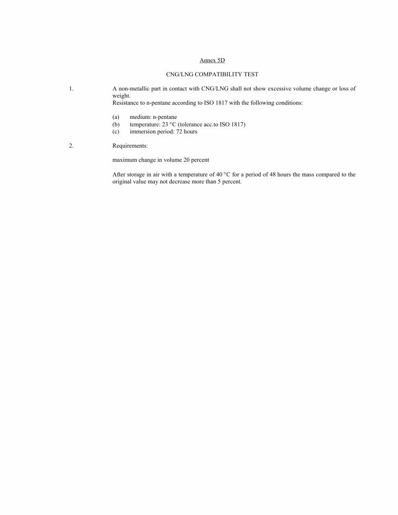
Annex 5D
CNG/LNG COMPATIBILITY TEST 1. A non-metallic part in contact with CNG/LNG shall not show excessive volume change or loss of
weight. Resistance to n-pentane according to ISO 1817 with the following conditions:
(a) medium: n-pentane (b) temperature: 23 C (tolerance acc.to ISO 1817) (c) immersion period: 72 hours
2. Requirements: maximum change in volume 20 percent After storage in air with a temperature of 40 C for a period of 48 hours the mass compared to the
original value may not decrease more than 5 percent.

Annex 5E
CORROSION RESISTANCE TEST Test procedures: 1. A metal CNG/LNG containing component shall comply with the leakage tests mentioned in Annexes
5B and 5C and after having been submitted to 144 hours salt spray test according to ISO 15500-2, with all connections closed.
2. A copper or brass CNG/LNG containing component shall comply with the leakage tests mentioned in
Annexes 5B and 5C and after having been submitted to 24 hours immersion in ammonia according to ISO CD 15500-2 with all connections closed.

Annex 5F
RESISTANCE TO DRY HEAT 1. The test has to be done in compliance with ISO 188. The test piece has to be exposed to air at a
temperature equal to the maximum operating temperature for 168 hours. 2. The allowable change in tensile strength should not exceed + 25 percent. The allowable change in
ultimate elongation shall not exceed the following values:
Maximum increase 10 percent Maximum decrease 30 percent
ANNEX 5G
OZONE AGEING 1. The test has to be in compliance with ISO 1431/1. The test piece, which has to be stressed to 20 percent elongation, shall be exposed to air at 40 °C with
an ozone concentration of 50 parts per hundred million during 72 hours. 2. No cracking of the test piece is allowed.

Annex 5H
TEMPERATURE CYCLE TEST
A non-metallic part containing CNG/LNG shall comply with the leakage tests mentioned in Annexes 5B and 5C after having been submitted to 96 hours temperature cycle from the minimum operating temperature up to the maximum operating temperature with a cycle time of 120 minutes, under maximum working pressure.
__________
Annex 5I
PRESSURE CYCLE TEST APPLICABLE ONLY TO CYLINDERS (SEE ANNEX 3)
_________
Annexes 5J and 5K - Not allocated
__________
Annex 5L
DURABILITY TEST (CONTINUED OPERATION)
Test method for CNG components: The component shall be connected to a source of pressurized dry air or nitrogen by means of a suitable fitting and subjected to the number of cycles specified for that specific component. A cycle shall consist of one opening and one closing of the component within a period of not less than 10 ± 2 seconds. (a) Room temperature cycling The component shall be operated through 96 percent of the total cycles at room temperature and at
rated service pressure. During the off cycle the down stream pressure of the test fixture should be allowed to decay to 50 percent of the test pressure. After that, the components shall comply with the leakage test of Annex 5B at room temperature. It is allowed to interrupt this part of the test at 20 percent intervals for leakage testing.
(b) High temperature cycling The component shall be operated through 2 percent of the total cycles at the appropriate maximum
temperature specified at rated service pressure. The component shall comply with the leakage test of Annex 5B at the appropriate maximum temperature at the completion of the high temperature cycles.
(c) Low temperature cycling The component shall be operated through 2 percent of the total cycles at the appropriate minimum
temperature specified at rated service pressure. The component shall comply with the leakage test of Annex 5B at the appropriate minimum temperature specified at the completion of the low temperature cycles.

178
Following cycling and leakage re-test, the component shall be capable of completely opening and closing when a torque not greater than that specified in Table 5.3 is applied to the component handle in a direction to open it completely and then in the reverse direction.
Table 5.3
Component inlet size (mm) Max. torque (Nm)
6 1.7 8 or 10 2.3
12 2.8
This test shall be conducted at the appropriate maximum temperature specified, and shall be repeated at a temperature of -40 C. Duration test for LNG

Annex 5M
BURST/DESTRUCTIVE TEST APPLICABLE ONLY TO CYLINDERS (SEE ANNEX 3)
_________
Annex 5N
VIBRATION RESISTANCE TEST All components with moving parts shall remain undamaged, continue to operate, and comply with the component's leakage tests after 6 hours of vibration in accordance with the following test method. Test method The component shall be secured in an apparatus and vibrated for 2 hours at 17 Hz with amplitude of 1.5 mm (0,06 in.) in each of three orientation axes. On completion of 6 hours of vibration the component shall comply with Annex 5C.

ANNEX 5O
OPERATING TEMPERATURES
Engine compartment Assembled on the engine On board Moderate (M) - 20 °C 105 °C - 20 °C 120 °C - 20 °C 85 °C Cold (C) - 40 °C 105 °C - 40 °C 120 °C - 40 °C 85 °C LNG (L) -162°C 105 °C - 162 °C 120 °C - 162 °C 85 °C
Note: the LNG (L) temperature is the temperature of the fluid inside the components. For surrounding temperatures use M or C. Since saturation temperature of LNG and pressure have a direct relationship as shown in the table below. Higher minimum temperatures shall be allowed for LNG components based on the described test pressure.
http://webbook.nist.gov/chemistry/fluid/Saturation
Temp Press [deg C] [barg]
-161.6 0-152.5 1-146.4 2-141.7 3-137.8 4-134.4 5-131.4 6-128.7 7-126.3 8-124.0 9-121.9 10-119.9 11-118.1 12-116.3 13-114.6 14-113.0 15-111.5 16-110.0 17-108.6 18-107.3 19-106.0 20-104.7 21-103.5 22-102.3 23-101.2 24

Annex 5P
LNG – LOW TEMPERATURE TEST
The component shall be operated through 96% of the total cycles (given in the Annex 4 of the product) at less -162°C temperature and working pressure. The component shall be operated through 4% of the total cycles at the appropriate maximum temperature (specified in Annex 5O) and working pressure and shall comply with Annex 5B and 5C at the completion of the temperature cycles. This test may be interrupted, if desired, at 20% intervals for leakage testing. Following cycling testing, perform the hydrostatic test.
182
Annex 5Q
COMPATIBILITY WITH HEAT EXCHANGE FLUIDS OF NON-METALLIC PARTS
The test samples shall be submerged in heat exchange medium for 168 hours at 90°C then they shall be dried for 48 hours at a temperature of 40°C. The composition of the heat exchange medium used of the test is water/ethylene-glycol fluid of 50%/50%. The test is deemed to be satisfactory if the change in volume is less than 20 percent, the change in mass is less than 5 percent, the change in tensile strength is less than -25 percent and the change in elongation at break is within -30 percent and + 10 percent.

Annex 6
PROVISIONS REGARDING CNG IDENTIFICATION MARK FOR PUBLIC SERVICE VEHICLES The sign consists of a sticker which must be weather resistant. The colour and dimensions of the sticker must fulfil the following requirements:
Colours:
Background: green Border: white or white reflecting Letters: white or white reflecting
Dimensions
Border width: 4 - 6 mm Character height: 25 mm Character thickness: 4 mm Sticker width: 110 - 150 mm Sticker height: 80 - 110 mm
The word "CNG" must be centred in the middle of the sticker.

184
Annex 7
PROVISIONS REGARDING LNG VEHICLES
PROVISIONS REGARDING LNG IDENTIFICATION MARK FOR PUBLIC SERVICE VEHICLES (M2 and M3)
The sign consists of a sticker which must be weather resistant. The colour and dimensions of the sticker must fulfil the following requirements:
Colours:
Background: green Border: white or white reflecting Letters: white or white reflecting
Dimensions
Border width: 4 - 6 mm Character height: 25 mm Character thickness: 4 mm Sticker width: 110 - 150 mm Sticker height: 80 - 110 mm
The word "LNG" must be centred in the middle of the sticker.