load and resistance factor design of w-shapes · pdf fileload and resistance factor design of...
TRANSCRIPT

Steel Design Guide Series
Load and Resistance Factor Design of
W-ShapesEncased in Concrete
© 2003 by American Institute of Steel Construction, Inc. All rights reserved.This publication or any part thereof must not be reproduced in any form without permission of the publisher.

Steel Design Guide Series
Load and ResistanceFactor Design ofW-Shapes Encasedin Concrete
Lawrence G. GriffisWalter P. Moore and Associates, Inc.Houston, Texas
A M E R I C A N I N S T I T U T E O F S T E E L C O N S T R U C T I O N
© 2003 by American Institute of Steel Construction, Inc. All rights reserved.This publication or any part thereof must not be reproduced in any form without permission of the publisher.

Copyright 1992 by American Institute of Steel Construction.All rights reserved. No part of this publication may be reproducedwithout written permission.
Published by the American Institute of Steel Construction, Inc.at One East Wacker Drive, Suite 3100, Chicago, IL 60601-2001.
© 2003 by American Institute of Steel Construction, Inc. All rights reserved.This publication or any part thereof must not be reproduced in any form without permission of the publisher.

TABLE OF CONTENTS
INTRODUCTION ............................................... 1
SCOPE ................................................................. 1
PART 1: USE AND DESIGN OFCOMPOSITE COLUMNS ................................ 1
Composite Frame Construction ......................... 1Practical Uses of Composite Columns............... 2Advantages, Disadvantages, and Limitations .... 2Practical Design Considerations ........................ 3
Fire Resistance ............................................... 3Longitudinal Reinforcing Bar Arrangement....... 3Ties ................................................................. 4Longitudinal Reinforcing Bar Splices ................ 4Connection of Steel Beam to Encased
Wide Flange ................................................... 5Shear Connectors ............................................. 5Base Plate ....................................................... 6Erection and Temporary Wind Bracing During
Composite Frame Construction...................... 1
Load and Resistance Factor Design (LRFD) ofComposite Columns.................................................. 7
Comparison Between LRFD and Strain Compatibility Methods ............................................. 8
Description of the Composite Beam-Column Load Tables ............................................................ 10
REFERENCES ........................................................... 11
NOMENCLATURE .................................................... 12
PART 2: SUGGESTED DETAILS FORCOMPOSITE COLUMNS ......................................... 13
PART 3: DESIGN EXAMPLES................................. 18
PART 4: LRFD COMPOSITE BEAM-COLUMN DESIGN TABLES ....................................................... 29
Instructions for Using LRFD Composite Beam- Column Design Tables ......................................... 29
PART 5: COMPOSITE COLUMN PROGRAMCMPOL ...................................................................... 310
© 2003 by American Institute of Steel Construction, Inc. All rights reserved.This publication or any part thereof must not be reproduced in any form without permission of the publisher.

PREFACE
This booklet was prepared under the direction of the Com-mittee on Research of the American Institute of Steel Con-struction, Inc. as part of a series of publications on specialtopics related to fabricated structural steel. Its purpose is toserve as a supplemental reference to the AISC Manual of SteelConstruction to assist practicing engineers engaged in build-ing design.
The design guidelines suggested by the authors that areoutside the scope of the AISC Specifications or Code do notrepresent an official position of the Institute and are notintended to exclude other design methods and procedures. Itis recognized that the design of structures is within the scopeof expertise of a competent licensed structural engineer,architect, or other licensed professional for the application ofprinciples to a particular structure.
The sponsorship of this publication by the American Iron andSteel Institute is gratefully acknowledged.
The information presented in this publication has been prepared in accordance with recognized engineeringprinciples and is for general information only. While it is believed to be accurate, this information should not beused or relied upon for any specific application without competent professional examination and verification ofits accuracy, suitability, and applicability by a licensed professional engineer, designer, or architect. Thepublication of the material contained herein is not intended as a representation or warranty on the part of theAmerican Institute of Steel Construction, Inc. or the American Iron and Steel Institute, or of any other personnamed herein, that this information is suitable for any general or particular use or of freedom infringement of anypatent or patents. Anyone making use of this information assumes all liability arising from such use.
© 2003 by American Institute of Steel Construction, Inc. All rights reserved.This publication or any part thereof must not be reproduced in any form without permission of the publisher.

LOAD AND RESISTANCE FACTOR DESIGN OFW-SHAPES ENCASED IN CONCRETE
INTRODUCTION
Structural members comprised of steel shapes in combinationwith plain or reinforced concrete have been utilized by engi-neers for many years. Early structures simply took advantageof the protection that the concrete afforded to the steel shapesfor resistance to fire and corrosion. But research on thestrength of such members was conducted in the early 1900s,1
and design provisions were formulated by 1924.2 More re-cently, with the advent of modern composite frame construc-tion in high rise buildings, engineers developed new rationalmethods to take advantage of the stiffening and strengtheningeffects of concrete and reinforcing bars on the capacity ofencased steel shapes.
This Guide presents design tables for composite columns,developed under the sponsorship of the American Institute ofSteel Construction (AISC) as an aid to the practicing struc-tural engineer in the application of the AISC Load and Resis-tance Factor Design (LRFD) Specification for StructuralSteel Buildings.3 The information presented supplements thatfound in the AISC LRFD Manual.4 Background on the LRFDcriteria for composite columns may be found in References 5and 6. Engineers interested in Allowable Stress Design (ASD)are encouraged to consider the procedure developed pre-viously by the Structural Stability Research Council (SSRC).7
The SSRC procedure is not presently included in the AISCASD Specification.8
The reader is cautioned that independent professional judg-ment must be exercised when data or recommendations setforth in this Guide are applied. The publication of the materialcontained herein is not intended as a representation or war-ranty on the part of the American Institute of Steel Construc-tion, Inc.—or any person named herein—that this informa-tion is suitable for general or particular use, or freedom frominfringement of any patent or patents. Anyone making use ofthis information assumes all liability rising from such use.The design of structures should only be performed by or underthe direction of a competent licensed structural engineer,architect, or other licensed professional.
SCOPE
This Guide is specifically for composite columns comprisedof rolled wide flange shapes encased in reinforced structuralconcrete with vertical deformed reinforcing bars and lateralties. Composite columns are defined in Section I1 of the
LRFD Specification as a "steel column fabricated from rolledor built-up steel shapes and encased in reinforced structuralconcrete or fabricated from steel pipe or tubing and filled withstructural concrete." Further, the Specification requires inSection I2.1 that the cross sectional area of the steel shapecomprise at least four percent of the total composite crosssection. The Commentary to the Specification states thatwhen the steel shape area is less, the column should bedesigned under the rules for conventional reinforced concretecolumns.
Part 1 of this Guide includes a discussion of compositeframe construction, practical uses of composite columns,their advantages and limitations, and a review of importantpractical design considerations. A summary of the pertinentLRFD rules is presented and compared to other methods. Aset of suggested design details is given in Part 2, showingplacement of reinforcing bars and ties, as well as treatment ofjoints and base plates. Five design examples are given inPart 3 to illustrate how the tables were derived and how theyare applied. Finally, a comprehensive set of tables is presentedin Part 4 to assist the designer in the rapid selection of themost economical section to resist required values of factoredload and moment.
PART 1: USE AND DESIGN OFCOMPOSITE COLUMNS
Composite Frame Construction
Although engineers since the 1930s have encased structuralsteel shapes in concrete for fireproofing and corrosion protec-tion, it was not until the development and popularity ofmodern composite frame construction in the 1960s that com-posite columns again became a common and viable structuralmember type. The late Dr. Fazlur Khan, in his early discus-sions of structural systems for tall buildings, first proposedthe concept of a composite frame system9, 10 utilizing compos-ite columns as part of the overall wind and earthquake resist-ing frame. Since that time composite frame construction hasbeen adopted for many high rise buildings all over the world.Its usage, with the composite column as the key element, iswell documented in the work of the Council on Tall Buildingsand numerous other publications.11-15
The term "composite frame structure" describes a buildingemploying concrete encased steel columns and a compositefloor system (structural steel and concrete filled steel deck).
1
© 2003 by American Institute of Steel Construction, Inc. All rights reserved.This publication or any part thereof must not be reproduced in any form without permission of the publisher.

The bare steel columns resist the initial gravity, construction,and lateral loads until such time as the concrete is cast aroundthem to form composite columns capable of resisting the totalgravity and lateral loads of the completed structure. In acomposite frame building, the structural steel and reinforcedconcrete combine to produce a structure having the advan-tages of each material. Composite frames have the advantageof speed of construction by allowing a vertical spread of theconstruction activity so that numerous trades can engagesimultaneously in the construction of the building. Inherentstiffness is obtained with the reinforced concrete to moreeasily control the building drift under lateral loads and reduceperception to motion. The light weight and strength obtainedwith structural steel equates to savings in foundation costs.
Traditionally in steel framed buildings or reinforced con-crete buildings, stability and resistance to lateral loads areautomatically provided as the structure is built. Welded orbolted moment connections are made or braces are connectedbetween columns in a steel building immediately behind theerection of the steel frame to provide stability and resistanceto lateral loads. Shear walls, or the monolithic casting ofbeams and columns, provide stability and resistance to lateralloads soon after the concrete has cured for reinforced concretebuildings. However, for composite frame structures, the finalstability and resistance to design lateral loads is not achievedtypically until concrete around the erection steel frame hascured, which typically occurs anywhere from a minimum ofsix to as much as 18 floors behind the erection of the baresteel frame. This sequence of construction is shown-schemati-cally in Fig. 1. Thus, as discussed subsequently, temporary
Fig. 1. Composite-frame construction sequence.
lateral bracing of the uncured portion of the frame willtypically be required.
Practical Uses of Composite ColumnsPractical applications for the use of composite columns canbe found in both low rise and high rise structures. In low risestructures such as a covered playground area, a warehouse, atransit terminal building, a canopy, or porte cochere, it maybe necessary or desirable to encase a steel column withconcrete for aesthetic or practical reasons. For example, ar-chitectural appearance, resistance to corrosion, or protectionagainst vehicular impact may be important. In such structures,it may be structurally advantageous to take advantage of theconcrete encasement of the rolled steel shape that supportsthe steel roof structure by designing the member as a compos-ite column resisting both gravity and lateral loads.
In high rise structures, composite columns are frequentlyused in the perimeter of "tube" buildings where the closelyspaced columns work in conjunction with the spandrel beams(either steel or concrete) to resist the lateral loads. In somerecent high rise buildings, giant composite columns placed ator near the corners of the building have been utilized as partof the lateral frame to maximize the resisting moment pro-vided by the building's dead load. Composite shear walls withencased steel columns to carry the floor loads have also beenutilized in the central core of high rise buildings. Frequently,in high rise structures where floor space is a valuable andincome producing commodity, the large area taken up by aconcrete column can be reduced by the use of a heavy encasedrolled shape to help resist the extreme loads encountered intall building design. Sometimes, particularly at the bottomfloors of a high rise structure where large open lobbies oratriums are planned, a heavy encased rolled shape as part ofa composite column is a necessity because of the large loadand unbraced length. A heavy rolled shape in a compositecolumn is often utilized where the column size is restrictedarchitecturally and where reinforcing steel percentages wouldotherwise exceed the maximum code allowed values.
Advantages, Disadvantages, and LimitationsSome of the advantages of composite columns are as follows:
1. Smaller cross section than required for a conventionalreinforced concrete column.
2. Larger load carrying capacity.3. Ductility and toughness available for use in earthquake
zones.4. Speed of construction when used as part of a composite
frame.5. Fire resistance when compared to plain steel columns.6. Higher rigidity when part of a lateral load carrying
system.7. Higher damping characteristics for motion perception in
tall buildings when part of a lateral load carrying system.
2
© 2003 by American Institute of Steel Construction, Inc. All rights reserved.This publication or any part thereof must not be reproduced in any form without permission of the publisher.

8. Stiffening effect for resistance against buckling of therolled shape.
There are also, of course, some disadvantages and limita-tions. In high rise composite frame construction, design en-gineers sometimes have difficulty in controlling the rate andmagnitude of column shortening of the composite columnwith respect to adjacent steel columns or shear walls. Theseproblems are exacerbated by the wide variation in construc-tion staging often experienced in the zone between the pointwhere the steel erection columns are first erected and the pointwhere concrete is placed around the steel to form the com-posite column. This variation in the number of floors betweenconstruction activities has made it difficult to calculate withaccuracy the effect of column shortening. Creep effects on thecomposite columns with respect to the all-steel core columns,or between shears walls, can also be troublesome to predictfor the designer. The net effect of these problems can be floorsthat are not level from one point to another. One solution tothese problems has been the measurement of column spliceelevations during the course of construction, with subsequentcorrections in elevation using steel shims to compensate fordifferences between the calculated and measured elevation.
As with any column of concrete and reinforcing steel, thedesigner must be keenly aware of the potential problems inreinforcing steel placement and congestion as it affects theconstructability of the column. This is particularly true atbeam-column joints where potential interference between asteel spandrel beam, a perpendicular floor beam, vertical bars,joint ties, and shear connectors can all cause difficulty inreinforcing bar placement and lead to honeycombing of theconcrete. Careful attention must be given to the detailing ofcomposite columns by the designer. Analytical and experi-mental research is needed in several aspects of compositecolumn design. One area requiring study is the need, or lackthereof, of a mechanical bond between the steel shape and thesurrounding concrete. Several papers16, 17 have discussed thisquestion, but additional work is required to quantify the needfor shear connectors with a practical design model for routinedesign office use. There presently is a question about transferof shear and moment through a beam-column joint. Thisconcern is of particular importance for seismic regions wherelarge cyclical strain reversals can cause a serious degradationof the joint. Initial research has been completed at the Uni-versity of Texas at Austin24 and is ongoing at Cornell Univer-sity on physical test models to study various joint details incomposite columns.
Practical Design Considerations
Fire ResistanceComposite columns, like reinforced concrete columns, havean inherent resistance to the elevated temperatures producedin a fire by virtue of the normal concrete cover to the reinforc-
ing steel and structural steel. It is standard practice to providea minimum of one and one-half inch of concrete cover to thereinforcing steel of a composite column (concrete cover isspecified in ACI 318-89 Section 7.7.1).18 Chapter 43 of theUniform Building Code states that reinforced concrete col-umns utilizing Grade A concrete (concrete made with aggre-gates such as limestone, calcareous gravel, expanded clay,shale, or others containing 40 percent or less quartz, chert, orflint) possess a four-hour rating with one and one-half inchcover. A four-hour rating is the maximum required for build-ing structures.
Tables of fire resistance rating for various insulating mate-rials and constructions applied to structural elements arepublished in various AISI booklets19, 20, 21 and in publicationsof the Underwriters Laboratory, Inc.
Longitudinal Reinforcing Bar Arrangement
Composite columns can take on just about any shape forwhich a form can be made and stripped. They can be square,rectangular, round, triangular, or any other configuration,with just about any corresponding reinforcing bar arrange-ment common to concrete columns. For use in compositeframe construction, however, square or rectangular columns
Fig. 2. Longitudinal bar arrangement in composite columns.
3
© 2003 by American Institute of Steel Construction, Inc. All rights reserved.This publication or any part thereof must not be reproduced in any form without permission of the publisher.

are the most practical shape, with bar arrangements tendingto place the vertical reinforcing bars at or near the four cornersof the column. Figure 2 shows preferred arrangements whichallow spandrel beams and a perpendicular floor beam toframe into the encased steel shape without interrupting thecontinuous vertical bars. Such arrangements also generate themaximum design capacity for the column.
Although there are no explicit requirements for longitudi-nal bar spacing in the LRFD Specification, it is advisable toestablish minimum limits so that concrete can flow readily inspaces between each bar and between bars and the encasedsteel shape.
Minimum spacing criteria will also prevent honeycombingand cracks caused by high bond stresses between bars. Pastexperience with reinforced concrete columns has shown thatthe requirements established by the ACI 318 Code haveprovided satisfactory performance. These spacing and coverrequirements have been used in the formulation of this designaid and as diagramed in Fig. 3 and listed below:
1. Minimum concrete cover over vertical bars and ties shallbe 1½-in. (LRFD Specification, Section I2.1.b).
2. Clear distance between longitudinal bars shall not be lessthan 1½ bar diameters or 1½-in. minimum (ACI 318-89Section 7.6.3).
Fig. 3. Composite column cover and bar spacing requirements.
3. The clear distance limitations apply also to contact lapsplices and adjacent bars (ACI 318-89 Section 7.6.4).
4. Clear distance between longitudinal bars and steel shapeshall be 1½ bar diameters or 1½-in. minimum.
TiesReinforcing steel cages (longitudinal bars and ties) mustusually be set after and around the steel column. Because thesteel column is erected in an earlier erection sequence, onlyopen U-shaped ties are suitable for composite columns. Tiesare used to provide lateral stability of the longitudinal barsand confinement of the concrete. The requirements of theLRFD specification and certain requirements of the ACI318-89 code not specifically addressed by the LRFD specifi-cation should be satisfied as follows:
1. The cross sectional area of the tie shall be at least 0.007square inches per inch of tie spacing (LRFD Specifica-tion I2.1.b).
2. The spacing of the ties shall not be greater than two-thirds of the least dimension of the cross section (LRFDSpecification I2.1.b).
3. The spacing of ties shall not be greater than 16 longitu-dinal bar diameters or 48 tie bar diameters (ACI 318-89Section 7.10.5.1).
4. Ties shall be at least #4 in size for #11, #14, #18, andbundled longitudinal bars, and #3 in size for all otherbars (ACI 318-89 Section 7.10.5.1).
5. Ties shall be arranged such that every corner and alter-nate bar shall have lateral support provided by a cornerof a tie, with an inclusive angle of not more than 135°and no bar shall be further than 6 inches clear on eachside along the tie from such a laterally supported bar(ACI 318-89 Section 7.10.5.3).
6. A lap splice of two pieces of an open tie shall be at leastequal to 1.3 times the tensile development length for thespecified yield strength (ACI 318-89 Section 12.13.5).
Suggested details for composite column ties are shown inTypical Details 1, 2, and 3 of Part 2.
Longitudinal Reinforcing Bar Splices
The requirements for splicing vertical longitudinal reinforc-ing bars for composite columns shall follow the same rules asapply for conventional reinforced concrete columns as speci-fied in Chapter 12 of the ACI 318-89 Code. Several additionalcomments should be made for composite columns. First,additional vertical longitudinal restraining bars (LRFDSpecification I2.1.b) should be used between the cornerswhere the continuous load carrying bars are located in com-posite frame construction. These bars usually cannot be con-tinuous because of interruption with intersecting framingmembers at the floor line. They are often required to satisfythe spacing requirements for vertical longitudinal bars shownas follows:
4
© 2003 by American Institute of Steel Construction, Inc. All rights reserved.This publication or any part thereof must not be reproduced in any form without permission of the publisher.
The cross section area of longitudinal reinforcementshall be at least equal to 0.007 square inches per inch ofbar spacing (LRFD Specification I2.1.b).
Second, it is suggested that, in high rise composite frameconstruction, the vertical bar splices be located at the middleclear height of the composite column. This point is usuallynear the inflection point (zero moment) of the column wherethe more economical compression lap splices or compressionbutt splices may be used. The more expensive tension lap ortension butt splices may be required if splices are made at thefloor line.
A suggested composite column splice detail is shown inTypical Detail 1 of Part 2.
Connection of Steel Beam to Encased Wide Flange
In composite frame construction, steel spandrel beams and/or perpendicular floor beams often frame into the compositecolumn at the floor level. Sometimes these beams will besimply supported floor beams where conventional double-angle framed beam connections (LRFD Manual, Part 5) orsingle-plate shear connections may be utilized. More often,however, the steel spandrel beams will be part of the lateralload resisting system of the building and require a momentconnection to the composite column. Practicality will oftendictate that the larger spandrel beam (frequently a W36 intall buildings) be continuous through the joint with thesmaller erection column (often a small W14) interrupted andpenetration welded to the flanges of the spandrel beam. Toincrease the speed of erection and minimize field welding,the spandrel beam and erection column are often prefabri-cated in the shop to form "tree columns" or "tree beams"with field connections at the mid-height of column andmidspan of spandrel beam using high strength bolts. SeeTypical Detail 5, Part 2.
The engineer must concern himself with the transfer offorces from the floor beams to the composite column. Forsimply supported beams not part of the lateral frame, thesimplest method to transfer the beam reaction to the compos-ite column is through a standard double-angle or single-plateshear connection to the erection column. It is then necessaryto provide a positive shear connection from the erectioncolumn to the concrete along the column length to ensuretransfer of the beam reaction to the composite column crosssection. The simplest method to accomplish this is by the useof standard headed shear connectors, preferably shop weldedto the wide flange column. For moment connected spandrelbeams, the beam shear and unbalanced moment must betransferred to the composite column cross section. Differenttransfer mechanisms have been tested at the University ofTexas at Austin.24
Several suggested details are shown in Details 1 and 2 ofPart 2.
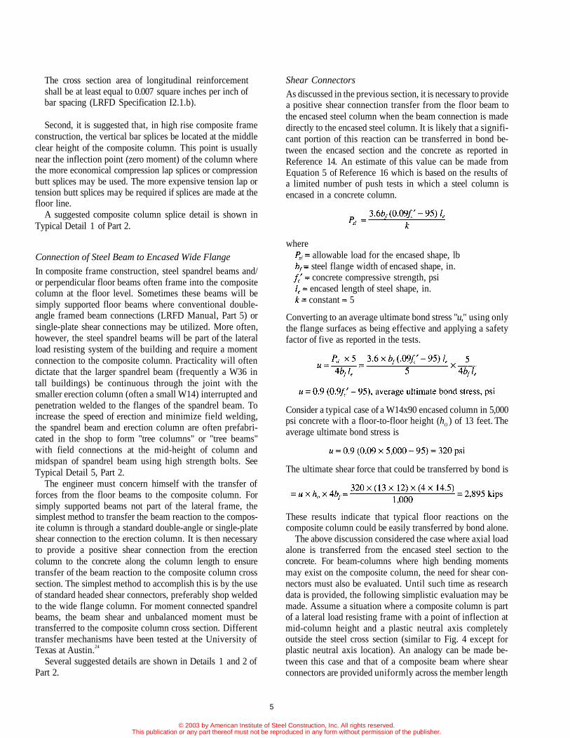
Shear Connectors
As discussed in the previous section, it is necessary to providea positive shear connection transfer from the floor beam tothe encased steel column when the beam connection is madedirectly to the encased steel column. It is likely that a signifi-cant portion of this reaction can be transferred in bond be-tween the encased section and the concrete as reported inReference 14. An estimate of this value can be made fromEquation 5 of Reference 16 which is based on the results ofa limited number of push tests in which a steel column isencased in a concrete column.
whereallowable load for the encased shape, lbsteel flange width of encased shape, in.concrete compressive strength, psiencased length of steel shape, in.constant 5
Converting to an average ultimate bond stress "u," using onlythe flange surfaces as being effective and applying a safetyfactor of five as reported in the tests.
Consider a typical case of a W14x90 encased column in 5,000psi concrete with a floor-to-floor height (hO ) of 13 feet. Theaverage ultimate bond stress is
The ultimate shear force that could be transferred by bond is
These results indicate that typical floor reactions on thecomposite column could be easily transferred by bond alone.
The above discussion considered the case where axial loadalone is transferred from the encased steel section to theconcrete. For beam-columns where high bending momentsmay exist on the composite column, the need for shear con-nectors must also be evaluated. Until such time as researchdata is provided, the following simplistic evaluation may bemade. Assume a situation where a composite column is partof a lateral load resisting frame with a point of inflection atmid-column height and a plastic neutral axis completelyoutside the steel cross section (similar to Fig. 4 except forplastic neutral axis location). An analogy can be made be-tween this case and that of a composite beam where shearconnectors are provided uniformly across the member length
5
© 2003 by American Institute of Steel Construction, Inc. All rights reserved.This publication or any part thereof must not be reproduced in any form without permission of the publisher.
between the point of zero moment and maximum moment.The ultimate axial force to be transferred between the encasedsteel column and the concrete over the full column height is2AFy where A is the steel column area and Fy is its yieldstrength. Assuming a bond strength is available in this casesimilar to the case of the push test discussed above, then shearconnectors would theoretically be required when 2AFy isgreater than the ultimate bond force. In the previous example,assume an A36 W 14×90 erection column is used. Then,
This is less than the available shear transfer from bond,which was calculated as 2,895 kips
Again, it is shown that bond stress alone can transfer theshear between the encased shape and the concrete, assumingno loss in bond occurs as a result of tensile cracking at highmoments.
The composite beam-column design tables presented inPart A assume a nominal flexural strength based on the plasticstress distribution of the full composite cross section. Tovalidate this assumption, the LRFD specification commen-tary in Section 14, requires a transfer of shear from the steelto the concrete with shear connectors. Therefore, until furtherresearch is conducted on the loss of bond between the encasedsteel section and the concrete, and until more comprehensivepush tests are run, the following suggestions are made withregard to shear connectors on composite columns:
1. Provide shear connectors on the outside flanges wherespace permits. Where space does not permit, provideshear connectors on the inside flange staggered eitherside of the web.
2. Provide shear connectors in sufficient quantity, spaceduniformly along the encased column length and aroundthe column cross section between floors, to carry the
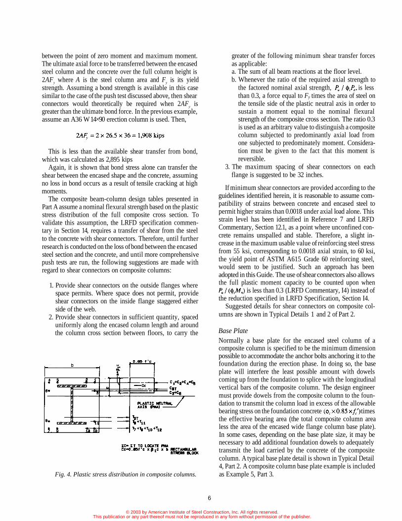
Fig. 4. Plastic stress distribution in composite columns.
greater of the following minimum shear transfer forcesas applicable:a. The sum of all beam reactions at the floor level.b. Whenever the ratio of the required axial strength to
the factored nominal axial strength, is lessthan 0.3, a force equal to Fy times the area of steel onthe tensile side of the plastic neutral axis in order tosustain a moment equal to the nominal flexuralstrength of the composite cross section. The ratio 0.3is used as an arbitrary value to distinguish a compositecolumn subjected to predominantly axial load fromone subjected to predominately moment. Considera-tion must be given to the fact that this moment isreversible.
3. The maximum spacing of shear connectors on eachflange is suggested to be 32 inches.
If minimum shear connectors are provided according to theguidelines identified herein, it is reasonable to assume com-patibility of strains between concrete and encased steel topermit higher strains than 0.0018 under axial load alone. Thisstrain level has been identified in Reference 7 and LRFDCommentary, Section 12.1, as a point where unconfined con-crete remains unspalled and stable. Therefore, a slight in-crease in the maximum usable value of reinforcing steel stressfrom 55 ksi, corresponding to 0.0018 axial strain, to 60 ksi,the yield point of ASTM A615 Grade 60 reinforcing steel,would seem to be justified. Such an approach has beenadopted in this Guide. The use of shear connectors also allowsthe full plastic moment capacity to be counted upon when
is less than 0.3 (LRFD Commentary, I4) instead ofthe reduction specified in LRFD Specification, Section I4.
Suggested details for shear connectors on composite col-umns are shown in Typical Details 1 and 2 of Part 2.
Base PlateNormally a base plate for the encased steel column of acomposite column is specified to be the minimum dimensionpossible to accommodate the anchor bolts anchoring it to thefoundation during the erection phase. In doing so, the baseplate will interfere the least possible amount with dowelscoming up from the foundation to splice with the longitudinalvertical bars of the composite column. The design engineermust provide dowels from the composite column to the foun-dation to transmit the column load in excess of the allowablebearing stress on the foundation concrete timesthe effective bearing area (the total composite column arealess the area of the encased wide flange column base plate).In some cases, depending on the base plate size, it may benecessary to add additional foundation dowels to adequatelytransmit the load carried by the concrete of the compositecolumn. A typical base plate detail is shown in Typical Detail4, Part 2. A composite column base plate example is includedas Example 5, Part 3.
6
© 2003 by American Institute of Steel Construction, Inc. All rights reserved.This publication or any part thereof must not be reproduced in any form without permission of the publisher.
Erection and Temporary Wind Bracing DuringComposite Frame Construction
Historically, a structural steel erector is accustomed to work-ing with a steel framed structure that is stabilized as the frameis constructed with moment connections or permanent crossbracing. Composite frames many times are not stable and notfully able to carry lateral loads until after the concrete ispoured and cured many floors behind. Because of this fact, itis incumbent on the engineer-of-record to state the assump-tions of bare steel frame stability in the contract documents.Either he designs and details the necessary temporary bracingon the drawings or requires the erector to engage a structuralengineer to provide it. The engineer-of-record is the mostappropriate person to provide this service by virtue of hisknowledge of the loads and familiarity with the overall struc-ture. Additional discussions about the design responsibility ofsteel frames during erection may be found in the AISC Codeof Standard Practice.22 A discussion of composite framesduring erection may be found in Reference 15.
Load and Resistance Factor Design (LRFD) ofComposite ColumnsTo qualify as a composite column under the LRFD Specifi-cation design procedure, the following limitations must besatisfied as defined in Section 12.1:
1. The cross sectional area of the steel shape, pipe, or tubingmust comprise at least four percent of the total compositecross section.
2. Concrete encasement of a steel core shall be reinforcedwith longitudinal load carrying bars, longitudinal bars torestrain concrete, and lateral ties. Longitudinal loadcarrying bars shall be continuous at framed levels; lon-gitudinal restraining bars may be interrupted at framedlevels. The spacing of ties shall be not greater thantwo-thirds of the least dimension of the composite crosssection. The cross sectional area of the transverse andlongitudinal reinforcement shall be at least 0.007 in.2 perinch of bar spacing. The encasement shall provide atleast 1½-in. of clear cover outside of both transverse andlongitudinal reinforcement.
3. Concrete shall have a specified compressive strengthfc' of not less than 3 ksi nor more than 8 ksi for normalweight concrete, and not less than 4 ksi for lightweightconcrete.
4. The specified minimum yield stress of structural steeland reinforcing bars used in calculating the strength ofa composite column shall not exceed 55 ksi.
The required design strength Pu of axially loaded compositecolumns is defined in the LRFD Specification, Section E2,with modification of certain terms according to Section I2.2.These rules are summarized as follows:
required axial strength
(E2-1 modified)
(E2-2 modified)
(E2-3 modified)
(E2-4 modified)
= resistance factor for compression = 0.85= gross area of steel shape= modified yield stress
(I2-1)= modified modulus of elasticity
(I2-2)= specified yield stress of structural steel column, ksi= modulus of elasticity of steel, ksi= effective length factor= unbraced length of column, in.= radius of gyration of steel shape in plane of buckling,
except that it shall not be less than 0.3 times theoverall thickness of the composite cross section inthe plane of buckling, in.
= net concrete area= gross area of composite section, in.2
= area of longitudinal reinforcing bars, in.2
= modulus of elasticity of concrete= unit weight of concrete, lbs./ft3
= specified compressive strength of concrete, ksi= specified minimum yield stress of longitudinal rein-
forcing bars, ksi= 0.7= 0.6= 0.2
The interaction of axial compression and flexure in theplane of symmetry on composite members is defined inSection H1.1, H1.2, and I4 as follows:
(H1-1a)
(H1-1b)
= required compressive strength, kips= nominal compressive strength, kips= required flexural strength, kip-in.= nominal flexural strength determined from plastic
7
© 2003 by American Institute of Steel Construction, Inc. All rights reserved.This publication or any part thereof must not be reproduced in any form without permission of the publisher.
stress distribution on the composite cross section,kip-in.
= resistance factor for compression = 0.85= resistance factor for flexure = 0.90
The following information on the determination of therequired flexural strength, Mu, is quoted from Section H1.2 ofthe LRFD Specification, with minor changes in symbols asprescribed in Section I2.
"In structures designed on the basis of elastic analysis,Mu may be determined from a second order elastic analysisusing factored loads. In structures designed on the basis ofplastic analysis, Mu shall be determined from a plastic analy-sis that satisfies the requirements of Sects. C1 and C2. Instructures designed on the basis of elastic first order analysisthe following procedure for the determination of Mu may beused in lieu of a second order analysis:
(H1-2)
where= required flexural strength in member assuming there
is no lateral translation of the frame, kip-in.= required flexural strength in member as a result of
lateral translation of the frame only, kip-in.
(H1-3)
where is defined by Formula E2-4 within the plane of bending.
= a coefficient whose value shall be taken as follows:
i. For restrained compression members in frames bracedagainst joint translation and not subject to transverseloading between their supports in the plane of bending,
(H1-4)
where M1 / M2 is the ratio of the smaller to largermoments at the ends of that portion of the memberunbraced in the plane of bending under consideration.M1 / M2 is positive when the member is bent in reversecurvature, negative when bent in single curvature.
ii. For compression members in frames braced against jointtranslation in the plane of loading and subjected totransverse loading between their supports, the value ofCm can be determined by rational analysis. In lieu of suchanalysis, the following values may be used:
for members whose ends are restrained, Cm = 0.85
for members whose ends are unrestrained, Cm = 1.0
(H1-5)
(H1-6)
= required axial load strength of all columns in astory, kips
= translation deflection of the story under considera-tion, in.
= sum of all story horizontal forces producingkips
= story height, in.kips, where is the slenderness para-
meter defined by Formula E2-4, in which theeffective length factor K in the plane of bendingshall be determined in accordance with Sect.C2.2, but shall not be less than unity."
The nominal flexural strength Mn is determined for theplastic stress distribution on the composite cross section asshown in Fig. 4. The plastic neutral axis is first determinedsuch that there is equilibrium of axial forces in the concrete,reinforcing steel and embedded steel column. The nominalflexural strength Mn is determined as the summation of thefirst moment of axial forces about the neutral axis. SeeExample 2, Part 3.
In the determination of the concrete compressive axialforce, a concrete compressive stress of 0.85fc' is assumeduniformly distributed over an equivalent stress block boundedby the edges of the cross section and a straight line parallel tothe plastic neutral axis at a distance where c is thedistance from the edge of the cross section to the plasticneutral axis, and,
These assumptions are contained in the ACI 318-89 Code(Section 10.2.7.3).
Comparison Between LRFD and StrainCompatibility MethodsGuidelines for the design of composite columns were firstintroduced into the ACI Building Code in 1971 (ACI 318-71).With the widespread use and popularity of composite col-umns in the 1970s and 1980s, many engineers designedcomposite columns according to these principles, which areessentially the same ones used for conventional reinforcedconcrete columns.
The current rules for designing composite columns by the
8
© 2003 by American Institute of Steel Construction, Inc. All rights reserved.This publication or any part thereof must not be reproduced in any form without permission of the publisher.

ACI approach are found in ACI 318-89, Chapter 10. Themethod essentially is one based on the assumption of a linearstrain diagram across the composite cross section with themaximum failure strain at ultimate load defined as 0.003.With these assumptions, it is possible to generate strengthcapacities of the cross section for successive assumed loca-tions of the neutral axis. Strains at each location of the crosssection are converted to stress for the usual assumption of alinear stress-strain curve for reinforcing steel and structuralsteel. The first moment of forces in each element of concrete,structural steel, and reinforcing steel is taken about the neutralaxis to generate a point (axial load and moment) on aninteraction curve.
A comparison between the strain compatibility approachand the LRFD approach is shown in Figs. 5 through 7.Interaction curves (axial load vs. moment) are plotted cover-ing the wide range of composite column sizes (28×28 in.,36×36 in., 48×48 in.) steel column sizes (minimum of fourpercent of the composite column cross section to maximumW 14×730) and reinforcing steel percentages (one percent tofour percent) that are likely to be found in practice. Examina-tion of these figures reveals the following comparison:
1. The ACI approach yields curves that are parabolic innature while the AISC curves are essentially bilinear.
2. The two methods yield pure moment capacities that arevery close to each other. The maximum difference isapproximately 15 percent with most values much closerthan that. LRFD in all cases predicts higher momentvalues.
3. The two methods yield pure axial load capacities that arereasonably close when the steel column constitutes asmall part of the total column capacity, but are signifi-cantly different as the steel column becomes larger. Withlarger steel column sizes, the LRFD approach yieldsaxial capacities as much as 30 percent larger than ACI.This comparison, however, is not very meaningful be-cause the ACI approach essentially does not recognizepure axially loaded columns with its minimum eccen-tricity provisions.
4. Large differences in capacity are predicted (as much as50 percent) for composite columns having small steelcolumns. The ACI method yields significantly largeraxial loads for a given moment than the LRFD method.This difference is most striking in the intermediate rangeof the curve.
5. With larger steel columns, the LRFD curve is mostlyabove (predicts higher values) the ACI curve. As thesteel column section becomes lighter, the ACI curvetends to be above the LRFD curve, particularly in themiddle ranges of eccentricity.
6. It can generally be stated that, as the steel columnbecomes a larger portion of the total column capacity,design economy can be realized by designing using theLRFD approach. When the steel column becomes
Fig. 5. Interaction curve comparisons ACI vs. LRFD. Fig. 6. Interaction curve comparisons ACI vs. LRFD.
9
© 2003 by American Institute of Steel Construction, Inc. All rights reserved.This publication or any part thereof must not be reproduced in any form without permission of the publisher.

smaller (the column is more like a conventional concretecolumn), the ACI method is more economical in design.
Reference 23 also presents a comparison of design methods.
Description of the Composite Beam-Column Load TablesDesign tables are presented in Part 4 of this Guide to assistthe engineer in the rapid selection of the most economicalcomposite column to resist factored values of axial load andmoment. The tables are based on the LRFD Specificationrequirements outlined in the previous sections. The tableshave been set up to follow the general format of the LRFDManual,4 including the column tables in Part 2 (Axial LoadedSteel Columns) and Part 4 (Axially Loaded Composite Col-umns) of the Manual, because these are already familiar tomost design engineers. The tables indicate the followingparameters from which the engineer can select a design (Referto sample table at beginning of Part 4 of this Guide):
Item 1: Composite Column Size (b × h, in.). The compositecolumn size (b × h) is indicated in inches in the upper rightcomer of the table. Note that the x- x axis is always the strongaxis of the steel column and is in the direction of b. The y-yaxis is always the weak axis of the steel column and is in thedirection of h. The table covers square and rectangular sizesvarying from 16 inches to 36 inches in four-inch increments.
Fig. 7. Interaction curve comparisons ACI vs. LRFD.
Item 2: Concrete Strength (f 'c , ksi). Concrete compressionstrength is indicated in the top right corner for 3 and 8ksi. All concrete is assumed to be normal weight concreteweighing 145 pcf. Linear interpolation can be used for con-crete strengths between 3 and 8 ksi.
Item 3: Reinforcing Bar Yield Strength (Fyr , ksi). All longitu-dinal and transverse reinforcing steel in the table is based onASTM A615 Grade 60 reinforcing steel.
Item 4: Steel Column Size. Steel column size is listed acrossthe top of the table. Sizes tabulated include all W8, W10,W12, and W14 wide flange shapes that are listed in the steelcolumn tables in Part 4 of the LRFD manual. They includeW8 (35 to 67), W10 (39 to 112), W12 (50 to 336), and W14(43 to 426).
Item 5: Steel Grade (Fy , ksi). Steel grade is presented acrossthe top of the page for both A36 and Grade 50 steel.
Item 6: Reinforcement. Information on column reinforce-ment is indicated in the extreme left column and includes thepercentage of vertical steel, area of steel (Ar , in.2) number,size of bar, pattern of vertical steel, and lateral tie size andspacing (see Fig. 2 for notation). The table covers steelpercentages as close as practical to 0.5 percent, 1 percent, 2percent, 3 percent, and 4 percent steel. If zeroes are tabulated,it indicates steel cover or spacing requirements could not besatisfied for the steel percentage indicated. Bar arrangementsand their designations are shown in Fig. 2.
Item 7: Unbraced Length (KL, ft). Axial load capacities aretabulated for unbraced lengths of 0, 11, 13, 17, 21, 25, and 40feet.
Item 8: Axial Design Strength (Nominal Axial Strength timesResistance Factor, kips). For each unbraced length,KL, equations E2-1, E2-2, E2-3, and E2-4 are used tocalculate the nominal axial strength which is multiplied by
and tabulated in the column marked 8.
Item 9, 10, and 11: Available Required Flexural Strength(Uniaxial Moment Capacity, ft-kips). For each ratioof applied factored axial load to times the nominal axialcapacity, available uniaxial moment capacity is tabu-lated by solving equation H1-1a or H1-1b as applicable. Notethat these moment capacities are uniaxial capacities and areapplied independently. Biaxial moment capacities are nottabulated.
Item 12: Euler Buckling Term ( kip-ft2). The secondorder moment, Mu, can be taken directly from a second orderelastic analysis, or it can be calculated from a first orderelastic analysis by using LRFD equations H1-1 through H1-6.To aid the designer in such a calculation, the terms and
are tabulated for each column configuration. The follow-ing definitions apply.
10
(f 'c )
© 2003 by American Institute of Steel Construction, Inc. All rights reserved.This publication or any part thereof must not be reproduced in any form without permission of the publisher.
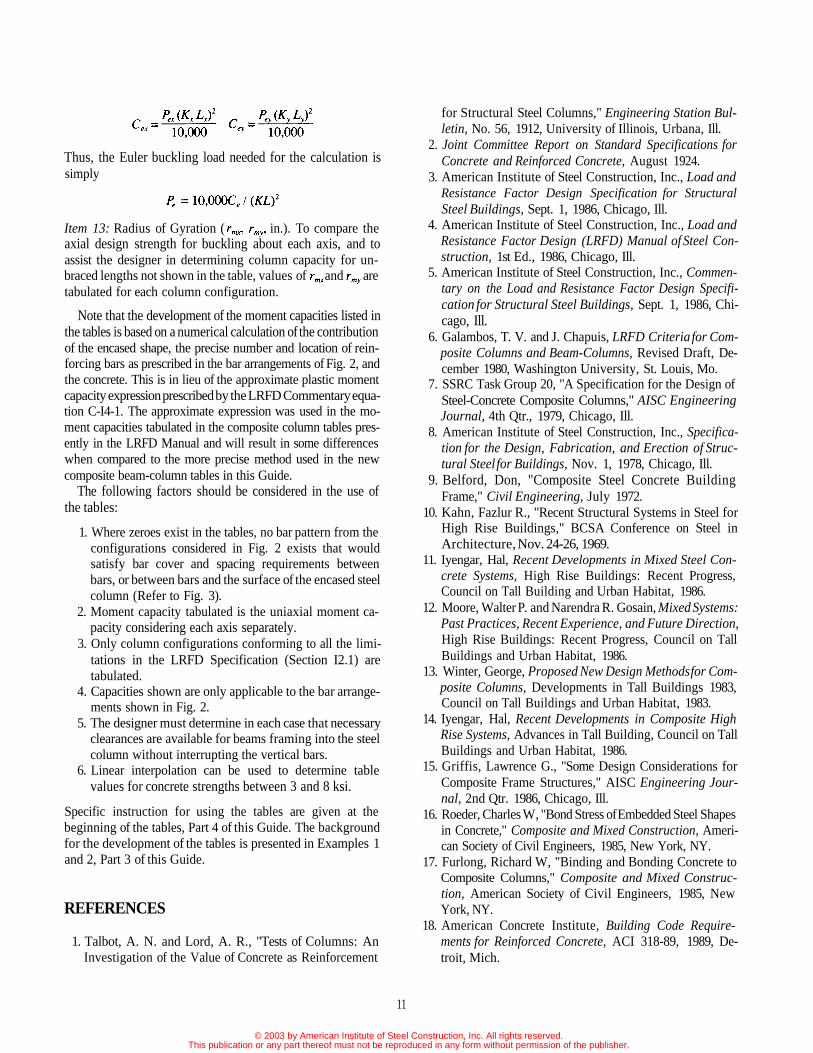
Thus, the Euler buckling load needed for the calculation issimply
Item 13: Radius of Gyration ( in.). To compare theaxial design strength for buckling about each axis, and toassist the designer in determining column capacity for un-braced lengths not shown in the table, values of and aretabulated for each column configuration.
Note that the development of the moment capacities listed inthe tables is based on a numerical calculation of the contributionof the encased shape, the precise number and location of rein-forcing bars as prescribed in the bar arrangements of Fig. 2, andthe concrete. This is in lieu of the approximate plastic momentcapacity expression prescribed by the LRFD Commentary equa-tion C-I4-1. The approximate expression was used in the mo-ment capacities tabulated in the composite column tables pres-ently in the LRFD Manual and will result in some differenceswhen compared to the more precise method used in the newcomposite beam-column tables in this Guide.
The following factors should be considered in the use ofthe tables:
1. Where zeroes exist in the tables, no bar pattern from theconfigurations considered in Fig. 2 exists that wouldsatisfy bar cover and spacing requirements betweenbars, or between bars and the surface of the encased steelcolumn (Refer to Fig. 3).
2. Moment capacity tabulated is the uniaxial moment ca-pacity considering each axis separately.
3. Only column configurations conforming to all the limi-tations in the LRFD Specification (Section I2.1) aretabulated.
4. Capacities shown are only applicable to the bar arrange-ments shown in Fig. 2.
5. The designer must determine in each case that necessaryclearances are available for beams framing into the steelcolumn without interrupting the vertical bars.
6. Linear interpolation can be used to determine tablevalues for concrete strengths between 3 and 8 ksi.
Specific instruction for using the tables are given at thebeginning of the tables, Part 4 of this Guide. The backgroundfor the development of the tables is presented in Examples 1and 2, Part 3 of this Guide.
REFERENCES
1. Talbot, A. N. and Lord, A. R., "Tests of Columns: AnInvestigation of the Value of Concrete as Reinforcement
for Structural Steel Columns," Engineering Station Bul-letin, No. 56, 1912, University of Illinois, Urbana, Ill.
2. Joint Committee Report on Standard Specifications forConcrete and Reinforced Concrete, August 1924.
3. American Institute of Steel Construction, Inc., Load andResistance Factor Design Specification for StructuralSteel Buildings, Sept. 1, 1986, Chicago, Ill.
4. American Institute of Steel Construction, Inc., Load andResistance Factor Design (LRFD) Manual of Steel Con-struction, 1st Ed., 1986, Chicago, Ill.
5. American Institute of Steel Construction, Inc., Commen-tary on the Load and Resistance Factor Design Specifi-cation for Structural Steel Buildings, Sept. 1, 1986, Chi-cago, Ill.
6. Galambos, T. V. and J. Chapuis, LRFD Criteria for Com-posite Columns and Beam-Columns, Revised Draft, De-cember 1980, Washington University, St. Louis, Mo.
7. SSRC Task Group 20, "A Specification for the Design ofSteel-Concrete Composite Columns," AISC EngineeringJournal, 4th Qtr., 1979, Chicago, Ill.
8. American Institute of Steel Construction, Inc., Specifica-tion for the Design, Fabrication, and Erection of Struc-tural Steel for Buildings, Nov. 1, 1978, Chicago, Ill.
9. Belford, Don, "Composite Steel Concrete BuildingFrame," Civil Engineering, July 1972.
10. Kahn, Fazlur R., "Recent Structural Systems in Steel forHigh Rise Buildings," BCSA Conference on Steel inArchitecture, Nov. 24-26, 1969.
11. Iyengar, Hal, Recent Developments in Mixed Steel Con-crete Systems, High Rise Buildings: Recent Progress,Council on Tall Building and Urban Habitat, 1986.
12. Moore, Walter P. and Narendra R. Gosain, Mixed Systems:Past Practices, Recent Experience, and Future Direction,High Rise Buildings: Recent Progress, Council on TallBuildings and Urban Habitat, 1986.
13. Winter, George, Proposed New Design Methods for Com-posite Columns, Developments in Tall Buildings 1983,Council on Tall Buildings and Urban Habitat, 1983.
14. Iyengar, Hal, Recent Developments in Composite HighRise Systems, Advances in Tall Building, Council on TallBuildings and Urban Habitat, 1986.
15. Griffis, Lawrence G., "Some Design Considerations forComposite Frame Structures," AISC Engineering Jour-nal, 2nd Qtr. 1986, Chicago, Ill.
16. Roeder, Charles W, "Bond Stress of Embedded Steel Shapesin Concrete," Composite and Mixed Construction, Ameri-can Society of Civil Engineers, 1985, New York, NY.
17. Furlong, Richard W, "Binding and Bonding Concrete toComposite Columns," Composite and Mixed Construc-tion, American Society of Civil Engineers, 1985, NewYork, NY.
18. American Concrete Institute, Building Code Require-ments for Reinforced Concrete, ACI 318-89, 1989, De-troit, Mich.
11
© 2003 by American Institute of Steel Construction, Inc. All rights reserved.This publication or any part thereof must not be reproduced in any form without permission of the publisher.
19. American Iron and Steel Institute, Washington, D.C., FireResistant Steel Frame Construction.
20. American Iron and Steel Institute, Washington, D.C.,Designing Fire Protection for Steel Columns.
21. American Iron and Steel Institute, Washington, D.C.,Designing Fire Protection for Steel Trusses.
22. American Institute of Steel Construction, Inc., Code ofStandard Practice for Steel Buildings and Bridges, Sept.1, 1986, Chicago, Ill.
23. Furlong, Richard W, "Column Rules of ACI, SSRC, andLRFD Compared," ASCE Journal of the Structural Divi-sion, Vol. 109, No. 10, (pp. 2375-2386) New York, NY.
24. Deierlein, Gregory G., Joseph A. Yura, and James O. Jirsa,Design of Moment Connections for Composite FramedStructures, Phil M. Ferguson Structural EngineeringLaboratory, Bureau of Engineering Research, the Univer-sity of Texas at Austin, May 1988.
NOMENCLATURE
= Area of base plate, in.2
= Full cross sectional area of concrete support, in.2
= Net concrete area, in.2
= Gross area of composite section, in.2
= Area of H-shaped portion of base plate, in.2
= Area of reinforcing bars, in.2
= Gross area of steel shape, in.2
= Base plate width, in.= Factors used in determining Mu for combined
bending and axial forces when first order analy-sis is employed
= Compression force in reinforcing bar, kips= Compressive force in concrete, kips= Factor for calculating Euler buckling strength,
kip-ft2
= Coefficient applied to bending term in interactionformula
= Modulus of elasticity of steel (29,000 ksi)= Modulus of elasticity of concrete, ksi= Modified modulus of elasticity, ksi= Critical stress, ksi= Modified yield stress, ksi= Specified minimum yield stress of the type of
steel being used, ksi= Specified minimum yield stress of reinforcing
bars, ksi= Horizontal force, kips= Effective length factor for prismatic member= Unbraced length of member measured between
the center of gravity of the bracing members, in.= Story height, in.= Smaller moment at end of unbraced length of
beam column, kip-in.
= Larger moment at end of unbraced length of beamcolumn, kip-in.
= Required flexural strength in member due tolateral frame translation, kip-in.
= Nominal flexural strength, kip-in.= Required flexural strength in member assuming
there is no lateral translation of the frame, kip-in.= Required flexural strength, kip-in.= Base plate length, in.= Euler buckling strength, kips= Nominal axial strength, kips= Factored load contributory to area enclosed by
steel shape, kips= Factored axial load resisted by steel shape, kips= Service load for encased shape limited by bond
stress, lbs= Required axial strength, kips= Ratio of required axial strength to factored
nominal axial strength= Tension force in reinforcing bar, kips= Tension force in steel shape, kips= Depth of compression block of concrete in com-
posite column, in.= Overall width of composite column, in.= Flange width, in.= Distance to outer fiber from plastic neutral axis, in.= Numerical coefficients for calculating modified
properties= Overall depth of member, in.= Concrete compressive stress, psi or ksi, as
applicable= Overall depth of composite column, in.= Floor-to-floor height, ft= Factor in bond strength calculation= Unbraced length of column, in.= Encased length of steel shape, in.= Cantilever distance in base plate analysis, in.= Cantilever distance in base plate analysis, in.= Radius of gyration, in.= Radius of gyration of steel shape in composite
column, in.= Spacing (clear distance), in.= Flange thickness, in.= Thickness of base plate, in.= Web thickness, in.= Unit weight of concrete, lbs/ft3
= Factor for determining depth of concrete incompression
= Translation deflection of story, in.= Column slenderness parameter= Resistance factor for flexure= Resistance factor for axially loaded composite
column
12
© 2003 by American Institute of Steel Construction, Inc. All rights reserved.This publication or any part thereof must not be reproduced in any form without permission of the publisher.

PART 2: SUGGESTED DETAILS FOR COMPOSITE COLUMNS
Typical Detail 1: Composite column elevation.
13
© 2003 by American Institute of Steel Construction, Inc. All rights reserved.This publication or any part thereof must not be reproduced in any form without permission of the publisher.

Typical Detail 2: Composite column cross section.
14
© 2003 by American Institute of Steel Construction, Inc. All rights reserved.This publication or any part thereof must not be reproduced in any form without permission of the publisher.

Typical Detail 3: Composite column joint.
15
© 2003 by American Institute of Steel Construction, Inc. All rights reserved.This publication or any part thereof must not be reproduced in any form without permission of the publisher.

Typical Detail 4: Composite column baseplate.
16
© 2003 by American Institute of Steel Construction, Inc. All rights reserved.This publication or any part thereof must not be reproduced in any form without permission of the publisher.

Typical Detail 5: Tree column in a composite frame.
17
© 2003 by American Institute of Steel Construction, Inc. All rights reserved.This publication or any part thereof must not be reproduced in any form without permission of the publisher.

PART 3: DESIGN EXAMPLES
Example 1:
Compute the axial load capacity of a 48×48-in. composite column with an encased W 14×730. Compute capacity forunbraced length equal to 11'-0 and 40'-0. Use = 5 ksi, Fyr = 60 ksi, 20 - #14 (6x - 6y) and wc = 145 pcf. See Fig. B-1.
W14×730 properties are:
Fig. B-1. Cross section for Examples 1 and 2.
Solution:
1. Compute section properties.
Total area of longitudinal reinforcing bars = 20 × 2.25 = 45.0 in.2
Gross section area of concrete column = 48 × 48 = 2,304 in.2
Percentage of longitudinal reinforcing bars = 45.0 / 2,340 = 1.95 percent
Percentage of steel shape = 2157 2,304 = 9.33 percent > 4 percent o.k.
Net area of concrete = 2,304 - 45 - 215 = 2,044 in.2
(Use = 60 ksi instead of 55 ksi limitations—see discussion under "Shear Connections")
18
© 2003 by American Institute of Steel Construction, Inc. All rights reserved.This publication or any part thereof must not be reproduced in any form without permission of the publisher.

Table A
COMPOSITE BEAM—COLUMN DESIGN CAPACITY — LRFD
Axial Load Capacity (kips), Uniaxial Moment Capacity (ft-kips) Column Size (b x h): 48 x 48
Designation
Fy (ksi)
Reinf.
#4 Ties
@28 in
#3 Ties
@15 in
#4 Ties
@28 in
#4 Ties
(5)28 in
#4 Ties
@28 in
KL
0111317212540
0111317212540
011
1317212540
011
1317212540
011
1317212540
W14x730
36
12300122001220012100120001190011300
11200
12700126001260012500124001230011600
11200
13400133001330013200131001290012200
11100
14000139001390013800136001350012700
11100
15100150001490014800147001450013600
11100
0.00.20.30.40.50.70.9
11200
0.00.20.30.40.50.70.9
11200
0.00.20.30.40.50.70.9
11100
0.00.20.30.40.50.70.9
11100
0.00.20.30.40.50.7
0.9
11100
817073506430551045902760918
14.40
9110820071706150512030701020
14.40
10700962084207220601036101200
14.40
125001120098308430702042101400
14.40
1460013200115009880824049401650
14.40
696062605480470039102350782
14.40
774069706090522043502610
870
14.40
9550860075206450537032201070
14.40
10500949083107120593035601190
14.40
123001110096808300691041501380
14.40
50
14900148001470014600145001430013400
11200
15300151001510015000148001460013700
11200
158001580015600155001530014300
11100
16600164001640016200161001580014700
11100
1760017500174001730017100
1680015600
11100
0.00.20.30.40.50.70.9
11200
0.00.20.30.40.50.70.9
11200
0.00.2
0.30.40.50.70.9
11100
0.00.20.30.40.50.70.9
11100
0.00.20.30.40.50.70.9
11100
10100908079506810568034101140
14.40
11000993086907440620037201240
14.40
12600113009930851070904260
14.40
1440013000113009720810048601620
14.40
16600149001300011200931055901860
14.40
797071706270538044802690
896
14.40
875078706890590049202950
983
14.40
95008310712059403560
14.40
115001040090907790649039001300
14.40
1330012000105008970747044801490
14.40
W14x665
36
11800117001170011600115001140010800
10400
12200121001210012000119001170011100
10400
12900128001270012600125001240011700
10400
13500134001330013200131001300012200
10300
1460014400144001430014100
1390013000
10300
0.00.20.30.40.50.70.9
10400
0.00.20.30.40.50.70.9
10400
0.00.20.30.40.50.70.9
10400
0.00.20.30.4
0.50.70.9
10300
0.00.20.30.4
0.50.70.9
10300
765068806020516043002580860
14.40
859077306760580048302900966
14.40
10200915080106860572034301140
14.40
120001080094208080673040401350
14.40
1410012700111009530794047701590
14.40
668060105260451037602260
751
14.40
747067205880504042002520840
14.40
9280835073106260522031301040
14.40
10300925080906940578034701160
14.40
120001080094708110676040601350
14.40
50
14100140001400013800137001350012700
10400
14500144001430014200141001390013000
10400
15200151001500014900147001450013600
10400
15800157001560015500153001510014000
10300
16900167001670016500163001610014800
10300
0.00.20.30.40.50.7
0.9
10400
0.00.20.30.40.50.70.9
10400
0.00.20.30.40.50.70.9
10400
0.00.20.30.4
0.50.70.9
10300
0.00.20.30.40.50.7
0.9
10300
9370844073806330527031601050
14.40
10300928081206960580034801160
14.40
119001070093708030669040101340
14.40
1370012300108009240770046201540
14.40
15800143001250010700891053501780
14.40
763068606010515042902570857
14.40
841075706620567047302840945
14.40
10200919080406900575034501150
14.40
112001010088307570631037801260
14.40
1290011700102008740728043701460
14.40
Notes: 1. KL in ft, and in inches.2. Zeroes in columns for and indicate that no suitable reinforcing bar arrangement is available for the indicated steel percentage.3. See Figure 2 lor definition of bar arrangement (roc - my). NW = normal weight concrete.4. and when
19
© 2003 by American Institute of Steel Construction, Inc. All rights reserved.This publication or any part thereof must not be reproduced in any form without permission of the publisher.

2. Axial load capacity
For KL = 0'-0
For KL=11'-0
For KL = 40'-0
The calculated values of agree with the values circled in Table A, Example 2, which have been rounded.
20
© 2003 by American Institute of Steel Construction, Inc. All rights reserved.This publication or any part thereof must not be reproduced in any form without permission of the publisher.

Example 2:
Compute the interaction curves of the composite column described in Example 1. See Fig. B-1.
Solution:
1. Coordinates of reinforcing bars.
No.
123456789
10
2.8467.079
11.3122.8462.846
45.15440.92136.68845.15445.154
y2.8462.8462.8467.079
11.3122.8462.8462.8467.079
11.312
No.x
11121314151617181920
2.8467.079
11.3122.8462.846
45.15440.92136.68845.15445.154
y45.15445.15445.15440.92136.68845.15445.15445.15440.92136.688
2. Nominal flexural strength about x-axis.
In general, successive approximations are required to determine the location of the plastic neutral axis. Here, trial valuesof the distance from the plastic neutral axis to the bottom of the section, Yb, and to the top of the section, Ya, are assumedas follows:
21
x
© 2003 by American Institute of Steel Construction, Inc. All rights reserved.This publication or any part thereof must not be reproduced in any form without permission of the publisher.

Concrete4.25 × 48 × 13.8445
Rebars1. -60 × 2.252. -60 × 2.253. -60 × 2.254. -60 × 2.255. -60 × 2.256. -60 × 2.257. -60 × 2.258. -60 × 2.259. -60 × 2.25
10. -60 × 2.2511. 55.75 × 2.2512. 55.75 × 2.2513. 55.75 × 2.2514. 55.75 × 2.2515. 55.75 × 2.2516. 55.75 × 2.2517. 55.75 × 2.2518. 55.75 × 2.2519. 55.75 × 2.2520. 55.75 × 2.25
Subtotal
Steel(50 - 0.85 × 5)(35.21 - 34.1555) × 17.8950 × (34.1555 - 30.6944) × 17.89-50 × (30.6944 - 30.3) × 17.89-50 × (30.3-17.7) × 3.07-50 × 4.91 × 17.89
Subtotal
Total
Force (kips)
2824.28
-135.0-135.0-135.0-135.0-135.0-135.0-135.0-135.0-135.0-135.0
125.4375125.4375125.4375125.4375125.4375125.4375125.4375125.4375125.4375125.4375
-95.625
863.073095.95-352.79
-1934.10-4392.00
-2728.87
-0.22
y-Yb (in.)
10.3834
-27.8484-27.8484-27.8484-23.6154-19.3824-27.8484-27.8484-27.8484-23.6154-19.3824
14.459614.459614.459610.22665.9936
14.459614.459614.459610.22665.9936
3.98841.7306
-0.1972-6.6944
-15.4494
Moment (ft-kips)
2443.80
313.29313.29313.29265.67218.05313.29313.29313.29265.67218.05151.15151.15151.15106.9062.65
151.15151.15151.15106.9062.65
4093.18
286.86446.49
5.801078.975654.47
7472.59
14009
Since the summation of forces is approximately zero, the assumed location of the plastic neutral axis is correct.
Calculate the uniaxial moment capacity from Eqs. H1-1a and H1-1b for assumed values of the load ratio
Points on the interaction curve are calculated as follows:
These values agree with the circled values in Table A.
3. Nominal flexural strength about y-axis.
Try
22
© 2003 by American Institute of Steel Construction, Inc. All rights reserved.This publication or any part thereof must not be reproduced in any form without permission of the publisher.

Concrete4.25 × 48 × 17.9565
Rebars1. -60 × 2.252. -60 × 2.253. -60 × 2.254. -60 × 2.255. -60 × 2.256. 55.75 × 2.257. 55.75 × 2.258. 55.75 × 2.259. 55.75 × 2.25
10. 55.75 × 2.2511. -60 × 2.2512. -60 × 2.2513. -60 × 2.2514. -60 × 2.2515. -60 × 2.2516. 55.75 × 2.2517. 55.75 × 2.2518. 55.75 × 2.2519. 55.75 × 2.2520. 55.75 × 2.25
Subtotal (Rebars)
Steel(50 - 0.85 × 5)(32.945 - 30.0435) × 4.91 × 250 × (30.0435 - 25.5544) × 4.91 × 2-50 × (25.5544 - 25.535) × 4.91 × 2-50 × 3.07 × 22.42-50 × 7.41 × 4.91 × 2
Subtotal (Steel)
Total
Force (kips)
3663.13
-135.0-135.0-135.0-135.0-135.0
125.4375125.4375125.4375125.4375125.4375
-135.0-135.0-135.0-135.0-135.0
125.4375125.4375125.4375125.4375125.4375
-95.625
1303.542204.15
-9.53-3441.47-3638.31
-3581.62
-14.12
x-Xb (in.)
13.4674
-22.7084-18.4754-14.2424-22.7084-22.708419.599615.366611.133619.599619.5996
-22.7084-18.4754-14.2424-22.7084-22.7084
19.599615.366611.133619.599619.5996
5.93992.2446
-0.0097-1.5544-6.7944
Moment (ft-kips)
4111.07
255.47207.85160.23255.47255.47204.88160.63116.38204.88204.88255.47207.85160.23255.47255.47204.88160.63116.38204.88204.88
4052.28
645.24412.29
0.01445.79
2060.01
3563.34
11730
These values agree with the circled values in Table A.
23
© 2003 by American Institute of Steel Construction, Inc. All rights reserved.This publication or any part thereof must not be reproduced in any form without permission of the publisher.

Example 3:
Design a 20×20-in. composite column with an encased W-shape to resist a factored axial load of 470 kips and a factoredmoment about the x-axis of 350 kip-ft. The loads are obtained from a second order analysis. Use = 5 ksi, = 60 ksi,
= 50 ksi, and KL= 17 ft.
Solution:
1. Calculate relative eccentricity:
2. Determine trial load ratio:
3. Calculate required axial strength:
4. Select trial column:
Try 20×20-in. composite column, W8×58 column, 4-#7 (2x - 2y)
5. Calculate load ratio for trial column:
6. Determine uniaxial moment capacity:
From Table B with
7. Compare to factored moment:
= 354 kip-ft (from Table B) > 350 kip-ft required o.k.
Use 20×20-in. composite column with W8×58 (Fy = 50 ksi), = 5 ksi, 4-#7 bars (2x - 2y) vertical bars and #3 ties at13 in.
24
© 2003 by American Institute of Steel Construction, Inc. All rights reserved.This publication or any part thereof must not be reproduced in any form without permission of the publisher.
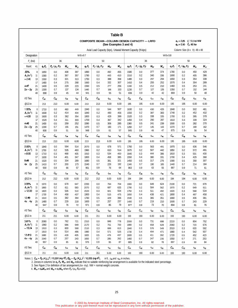
Table B
COMPOSITE BEAM—COLUMN DESIGN CAPACITY — LRFD(See Examples 3 and 4)
Axial Load Capacity (kips), Uniaxial Moment Capacity (ft-kips) Column Size (b x h): 48 x 48
Designation
Fy (ksi)
Reinf.
#3 Ties
@13 in
#3 Ties
@13 in
#3 Ties
@13 in
#3 Ties
@13 in
#3 Ties
@13 in
KL
0111317212540
0111317212540
0111317212540
011131721
2540
0111317212540
W8x67
36
165015801550148014001300898
213
171016301600152014301330908
213
184017501710163015201410930
212
197018601820173016101480947
211
208019601910181016801540957
211
0.00.20.30.40.50.70.9
213
0.00.20.30.40.50.70.9
213
0.00.20.30.40.50.70.9
212
0.00.20.30.40.50.70.9
211
0.00.20.30.40.50.70.9
211
40836732127522913745
6.00
46041436231125915551
6.00
59453546840133420066
6.00
679611535458382229
76
6.00
762686600514428257
85
6.00
39735731326822313444
6.00
449404354
30325215150
6.00
51446340534728917357
6.00
647583510437364
21872
6.00
72164956848640524381
6.00
50
189017901750166015601440941
213
194018401800170015901470948
213
207019601910180016801540961
212
220020702020190017601600971
211
231021702110198018201650976
211
0.00.20.30.40.50.70.9
213
0.00.20.30.40.50.70.9
213
0.00.20.30.40.50.70.9
212
0.00.20.30.40.50.70.9
211
0.00.20.30.40.50.70.9
211
49244338833227716655
6.00
54449042936730618361
6.00
67861053445838122976
6.00
76468760151542925785
6.00
84676166657147628595
6.00
45541035830725615351
6.00
50745639934228517157
6.00
57151445038532119264
6.00
70463355447539623779
6.00
77870061352543726287
6.00
W8x58
36
158015101480141013301230836
195
163015501520145013601260845
195
176016701640155014501340863
194
190017901750165015301400877
193
200018801840173016001460885
193
0.00.20.30.40.50.70.9
195
0.00.20.30.40.50.70.9
195
0.00.20.30.40.50.70.9
194
0.00.20.30.4
0.50.70.9
193
0.00.20.30.40.50.70.9
193
37734029725521212742
6.00
43038733829024114548
6.00
56350744438031719063
6.00
64958451143836521973
6.00
731658576494411247
82
6.00
37433629425221012642
6.00
42638333528723914347
6.00
49144238633127616555
6.00
62456249242135121070
6.00
69862854947139223578
6.00
50
178016901650157014601350869
195
184017401700161015001370875
195
197018501810170015801440887
194
210019701920180016601500894
193
221020602010188017201550897
193
0.00.20.30.40.50.70.9
195
0.00.20.30.40.50.70.9
195
0.00.20.30.40.50.70.9
194
0.00.20.30.40.50.70.9
193
0.00.20.30.40.50.7
0.9
193
45040535430425315250
6.00
50245239533928216956
6.00
63657250142935821471
6.00
72164956848740624381
6.00
80472363354245227190
6.00
42938633828924114448
6.00
48143237832427016254
6.00
54649143036830718461
6.00
67961153445838122976
6.00
752676592507423253
84
6.00
Notes: 1. KL in ft, and in inches.2. Zeroes in columns lor and indicate that no suitable reinforcing bar arrangement is available for the indicated steel percentage.3. See Figure 2 for definition of bar arrangement (nx- my). NW = normal weight concrete.4. and when
25
© 2003 by American Institute of Steel Construction, Inc. All rights reserved.This publication or any part thereof must not be reproduced in any form without permission of the publisher.

Example 4:Design a 20×20-in. composite column with an encased W-shape to resist a factored axial load of 1,190 kips and a factoredmoment about the x-axis of 180 kip-ft. The loads are obtained from a second order analysis. Use = 5 ksi, = 60 ksi,Fy = 50 ksi, and KL = 17 ft.
Solution:1. Calculate relative eccentricity:
2. Determine trial load ratio:
3. Calculate required axial strength:
4. Select trial column:
Try 20×20-in. composite column, W8×67 column, 4-#9 (2x - 2y)
5. Calculate load ratio for trial column:
6. Determine uniaxial moment capacity:
From Table B with
7. Compare to factored moment:
= 183 kip-ft (from Table B) > 180 kip-ft required o.k.
Use 20×20-in. composite column with W8×67 (Fy = 50 ksi), = 5 ksi, 4-#9 bars (2x - 2y) vertical bars and #3 ties at13 in.
26
© 2003 by American Institute of Steel Construction, Inc. All rights reserved.This publication or any part thereof must not be reproduced in any form without permission of the publisher.

Example 5:Design the base plate of a 18×18-in. composite column with an encased W10×54 of Fy = 36 ksi, = 8 ksi, and 4-#8 grade60 longitudinal bars. Factored axial load Pu = 1,000 kips, KL = 31 ft. Use = 3 ksi for footing. Assume SeeFig. B-2 for nomenclature. Refer to AISC LRFD Manual, p. 2-101 for base plate design procedure.
Solution:
Base plate will be designed for the portion of the factored axial load resisted by the W10×54.
W10×54 properties:
Try base plate 12×12 in.
1. Compute axial load carried by W10×54 based on the contribution of W10×54 to the total column capacity.
Portion of factored axial load resisted by W10×54 is:
2. Compute m and n.
factored load contributory to area enclosedby steel shape, kipsFactored axial load resisted by steelshape, kipsArea of base plate, in.2
Full cross sectional area of concretesupport, in.2
Area of H-shaped portion of base plate inlight columns, in.2
Specified minimum yield stress of steel, ksiSpecified compressive strength ofconcrete, ksiThickness of base plate, in.Resistance factor for concrete = 0.6Resistance factor for base plate = 0.9
Fig. B-2. Column base plates.
27
© 2003 by American Institute of Steel Construction, Inc. All rights reserved.This publication or any part thereof must not be reproduced in any form without permission of the publisher.

3. Concrete bearing stress.
4. Check concrete bearing under base plate.
6. Compute area of H-shaped region.
7. Compute c.
8. Compute base plate thickness.
Use ¾-in. plate.
9. Design dowels to foundation.
Allowable compression transfer by concrete:
Required compression transfer by concrete:
Required area of dowels:
Use 4-#8, As (provided) = 4 × 0.79 = 3.16 in.2 > 3.11 o.k.
Embed dowels 22 bar diameters (for 3,000 psi concrete) into foundation (ACI 318-89 Section 12.3.1) = 22 × 1.00 =22 in.
Dowel projection into column = 30 bar diameters (ACI 318-89 Section 12.16.1) = 30 × 1.00 = 30 in.
28
5. Compute factored load contributary to the area enclosed by W10×54.
© 2003 by American Institute of Steel Construction, Inc. All rights reserved.This publication or any part thereof must not be reproduced in any form without permission of the publisher.

PART 4: LRFD COMPOSITEBEAM-COLUMN DESIGN TABLES
Instructions for Using LRFD CompositeBeam-Column Design Tables1. Determine the relative magnitude of the column eccentric-
ity by dividing the applied factored moment, Mu (ft-kips),by the product of the applied factored axial load, Pu (kips),and the composite column dimension in the plane of bend-ing, t.
2. Select a first trial value of the load ratio, Ru, depending on
the relative magnitude of eccentricity calculated from stepone, as follows:
5. Compute the load ratio, for the trial columnselected.
29
3. Compute required axial design strength
4. For a given desired column size (b × h) and concretestrength , and a known effective unbraced length (KL),select a trial column having approximately equalto Pu.
6. From the Table, for as calculated fromStep 5, find the uniaxial moment capacity asapplicable).
7. Compare to the factored moment.
If (and reasonably close to), trial columnis satisfactory.
If trial column is not satisfactory.
8. If column is not satisfactory, repeat steps four throughseven with a new trial column. Adjustments to get therequired capacity can be made by changing any of thefollowing variables:
a. column sizeb. concrete strengthc. WF column sized. percentage of vertical steel
If reenter the Tables with a largerratio.
If reenter the Tables with a smallerratio.
© 2003 by American Institute of Steel Construction, Inc. All rights reserved.This publication or any part thereof must not be reproduced in any form without permission of the publisher.

The tabular information in the printed version of this design guide (pages 30through 309) has been omitted in the posted version to minimize the file
size.
The tables are available in hard copy to members and ePubs subscribers free of charge by contacting [email protected], or 866.ASK.AISC.
© 2003 by American Institute of Steel Construction, Inc. All rights reserved.This publication or any part thereof must not be reproduced in any form without permission of the publisher.

PART 5: COMPOSITE COLUMNPROGRAM CMPOL
A computer program named CMPOL has been developed togenerate composite column design tables as described inPart 4. The program may be used to generate the tables ineither LRFD or ASD format. It is available through AISC. Forfurther information and/or to place your software order, call(312) 670-2400.
The program is contained on a high quality 5¼-in. disketteor 3½-in. disk in executable form and may be copied to a harddisk. It will run on any IBM compatible computer (PC/XT/AT286 or 386 or Model PS/2) with at least 512K installed RAM.A math coprocessor is optional.
The input data for CMPOL is all interactive. The procedurefor running the program is as follows:
1. Access drive A or go to the subdirectory containing theprogram if it is located on the hard disk.
2. Set the printer in a condensed mode. This can be doneby typing CONDENSE to invoke a batch file namedRCOMP.BAT. The batch file automatically uncondensesthe printer after the printing is finished.
3. Type CMPOL. A heading will appear on the screenfollowed by a question as to where the output is to bedirected. Enter 2 for printer.
4. Questions will appear on the screen prompting the userto enter the following data:
• Design Method. Enter 1 for LRFD, 2 for the approxi-mate procedure as used in the LRFD Manual anddescribed in the text to this guide, 3 for ASD.
• Unbraced Length (ft). Input 7 values of unbracedlength desired.
• Vertical Reinforcing Bar Splice Type. (1 = bearing ormechanical butt splice, 2 = normal lap splice, 3 =tangential lap splice.) This selection impacts the barpositioning for clearance and cover checks.
• Column Width (in.). Input minimum, maximum, and
increment of column width. If the minimum andmaximum are equal, then enter the increment as 1 toavoid an error.
• Column Depth (in.). Input minimum, maximum, andincrement of column depth as described above forcolumn width.
• Concrete strength (ksi). Input minimum, maximum,and increment of 28 day concrete strength enteringthe increment of 1 if the minimum and maximum areequal.
• Concrete Unit Weight (pcf). This value is used inthe determination of the modulus of elasticity forconcrete.
• Clear cover to reinforcing steel (in.). Input clear coverto reinforcing steel each direction and clear cover torolled shape. All three values will normally be 1.5 in.
• Reinforcing Steel Yield Strength (ksi).• Reinforcing Steel Size (integer number). Input mini-
mum and maximum size of vertical reinforcing barsdesired.
• Reinforcing Steel Ratio (decimal number, i.e., 0.01).Input five percentages of reinforcing steel to be ana-lyzed (typically 0.005, 0.01, 0.02, 0.03, 0.04).
• Beam Clearance, Each Direction (in.). This numberdefines the clearance at the centerline of the columnin each direction which is to be kept clear of verticalbars so that a beam may frame to the embedded rolledshape.
• Embedded WF Shape. Nominal Depth (in.) Weight(PLF). Input the minimum and maximum W shapesize to be included in the tables.
5. Tabular output will be sent to the printer and will be asshown in Appendices C and D. Note that some printersmay not print the character "phi" in which case it willappear as an "m." A sample input screen and output areshown on the following pages.
310
© 2003 by American Institute of Steel Construction, Inc. All rights reserved.This publication or any part thereof must not be reproduced in any form without permission of the publisher.

Design method (1 = LRFD exact, 2 = LRFD approximate, 3 = ASD)? - - - - - - - 1Input 7 unbraced length (ft) to be analyzed?- - - - - - - - - - - - - - - - - - - - - - - - - 0 11 13 17 21 25 40Type of splice (1 = bearing, 2 = normal lap, 3 = tangential lap)? - - - - - - - - - - - 3Input min., max. & increment of column width (in)? - - - - - - - - - - - - - - - - - - - - 32 32 1Input min., max. & increment of column depth (in)?- - - - - - - - - - - - - - - - - - - - 32 32 1Input min., max. & increment of concrete fc (ksi)? - - - - - - - - - - - - - - - - - - - - - 3 3 1Input unit weight of concrete (pcf)? - - - - - - - - - - - - - - - - - - - - - - - - - - - - - - - 145Input clear cover CRx, CRy, CRw (in)?- - - - - - - - - - - - - - - - - - - - - - - - - - - - - 1.5 1.5 1.5Input fy (ksi) of reinforcing steel? - - - - - - - - - - - - - - - - - - - - - - - - - - - - - - - - - 60Input min., max. size of reinforcing steel?- - - - - - - - - - - - - - - - - - - - - - - - - - - 7 18Input 5 percentages of reinf. steel to be analyzed? - - - - - - - - - - - - - - - - - - - - .005 .01 .02 .03 .04Input beam clearance reqd. in N-S & E-W dir. (in)? - - - - - - - - - - - - - - - - - - - - 5.5 5.5Input min., max W shape (ND1, ND2, NW2)?-- - - - - - - - - - - - - - - - - - - - - - - 12 152 12 170
Do you want to run CMPOL again (1 = yes, 0 = no)?- - - - - - - - - - - - - - - - - - - 0
Stop—program terminated.
C: I READY I CMPOL
311
- -
-
---
-
© 2003 by American Institute of Steel Construction, Inc. All rights reserved.This publication or any part thereof must not be reproduced in any form without permission of the publisher.

COMPOSITE BEAM-COLUMN DESIGN CAPACITY - LRFD
Axial Load Capacity (kips). Uniaxial Moment Capacity (ft-kips)
= 0.85 f'c : 3.0 ksi NW= 0.90 Fyr : 60 ksi
Column Size(b x h): 18 x 18Designation
Fy (ksi)Reinf.
.74 XAr ( in 2 )= 2.40
4-# 72x-2y
#3 Ties@ 12 in
.98 XA r ( i n 2 )= 3.16
4-# 82x-2y
#3 Ties@ 12 in
1.95 XA r ( i n 2 )- 6.32
8-# 84x-2y
#3 Ties@ 12 in
2.93 XAr ( in 2 )= 9.48
12-# 84x-4y
#3 Ties@ 12 in
3.85 XAr( in 2 )=12.48
8-#114x-2y
#4 Ties@ 12 in
KL0
1317212540
11
17212540
0111317212540
0111317212540
0111317212540
W 8 x 6736
1150110010801030974909630Cex150
1180112011001050992924635Cex150
12801220120011401070987654Cex150
139013201290122011401050669Cex149
149014101380130012001100679Cex149
0.00.20.30.40.50.70.9Cey150
0.00.20.30.40.50.70.9Cey150
0.00.20.30.40.50.70.9Cey150
0.00.20.30.40.50.70.9Cey149
0.00.20.30.40.50.70.9Cey149
Mux32829525822118411036
rmx5.40
35031527523619611839
rmx5.40
44339934929924914949
rmx5.40
50245139533828216956
rmx5.40
60754647840934120468
rmx5.40
Muy2792512191881579431
rmy5.40
30027023620316910133
rmy5.40
34431027123219311638
rmy5.40
43739334429524514749
rmy5.40
45841336130925815451
rmy5.40
138013101280122011301040671Cex150
141013301300123011501060674Cex150
152014301400132012201110684Cex150
163015201490139012901160691Cex149
173016101570147013501210694Cex149
50
0.00.20.30.40.50.70.9Cey150
0.00.20.30.40.50.70.9Cey150
0.00.20.30.40.50.70.9Cey150
0.00.20.30.40.50.70.9Cey149
0.00.20.30.40.50.70.9Cey149
Mux40936832227623013846
rmx5.40
43138833929124214548
rmx5.40
52447241335429517759
rmx5.40
58352445939332819665
rmx5.40
68861954246438723277
rmx5.40
Muy31928725121517910735
rmy5.40
34130626823019111538
rmy5.40
38434630325921612943
rmy5.40
47742937532226816153
rmy5.40
49844839233628016856
rmy5.40
W 8 x 58
107010301010960905842576Cex135
110010501030980923857581Cex135
1210115011201060995918598Cex135
13201240121011501070975610Cex135
142013301300122011301030618Cex134
36
0.00.20.30.40.50.70.9Cey135
0.00.20.30.40.50.70.9Cey135
0.00.20.30.40.50.70.9Cey135
0.00.20.30.40.50.70.9Cey135
0.00.20.30.40.50.70.9Cey134
Mux29826823420116710033
rmx5.40
32028825221618010836
rmx5.40
41337232527923213946
rmx5.40
47242437131826515953
rmx5.40
57751945438932419464
rmx5.40
Muy2632372071771488829
rmy5.40
2852562241921609632
rmy5.40
32929625922218511137
rmy5.40
42137933228423714247
rmy5.40
44339934929924914949
rmy5.40
12801210118011201040957609Cex135
13001230120011401060970612Cex135
141013301290122011301020621Cex135
152014201380130011901080626Cex135
162015101470137012501120627Cex134
50
0.00.20.30.40.50.70.9Cey135
0.00.20.30.40.50.70.9Cey135
0.00.20.30.40.50.70.9Cey135
0.00.20.30.40.50.70.9Cey135
0.00.20.30.40.50.70.9Cey134
Mux36733128924820612441
rmx5.40
38935030626321913143
rmx5.40
48343438032627116354
rmx5.40
54148742636530418260
rmx5.40
646582509436363218
72rmx
5.40
Muy30027023620216810133
rmy5.40
32128925321718010836
rmy5.40
36532828724620512341
rmy5.40
45741236030925715451
rmy5.40
47943137732326916153
rmy5.40
Notes : 1. Cex = Pex(KxLx)2/10000. (k ip- f t 2 ) , Cey = Pey(KyLy)2/10000. (k ip- f t 2 ) , KL in f t , rmx & rmy in inches.2. Zeroes in columns for , Mux, and Muy indicate that no suitable reinforcing bar arrangement is available
for the indicated steel percentage.3. See Figure 2 for definition of bar arrangement (nx-my). NW = Normal wt. concrete.4. Mux = and Muy = when * 0.0
312
© 2003 by American Institute of Steel Construction, Inc. All rights reserved.This publication or any part thereof must not be reproduced in any form without permission of the publisher.

DESIGN GUIDE SERIESAmerican Institute of Steel Construction, Inc.One East Wacker Drive, Suite 3100Chicago, Illinois 60601-2001
Pub. No. D806 (3M793)
© 2003 by American Institute of Steel Construction, Inc. All rights reserved.This publication or any part thereof must not be reproduced in any form without permission of the publisher.