load testing of drilled shaft foundations in limestone...
TRANSCRIPT
ADSC SE Chapter 1 Nashville Rock Load Tests, 2008
Dan A. Brown and Associates Consulting Geotechnical Engineers
300 Woodland Rd. (423)942-8681 Sequatchie, TN 37374 fax:(423)942-8687
Load Testing of Drilled Shaft Foundations in Limestone, Nashville, TN Dan Brown, P.E., Ph.D.
Introduction Drilled shafts constructed to bear on or within rock provide an extremely reliable
foundation system as a result of the ability of the geotechnical design engineer to observe and verify both the bearing stratum and the structural integrity of each drilled shaft foundation. Individual drilled shafts in rock are capable of supporting extremely high design loads, approaching the structural capacity of the reinforced column itself.
Because of the large load capacity of these foundations, it is relatively difficult and
expensive to conduct full scale load tests. As a result, the bearing capacity of drilled shafts in rock has traditionally been assessed very conservatively. In Nashville and similar areas, rock-bearing shafts are traditionally designed on the basis of end bearing alone with an allowable base resistance of around 80 to 100 ksf on rock that is verified by probe holes to be free of soil seams within two diameters below the base.
As a part of an ongoing research project to improve design methods and cost-efficiency
of rock-supported drilled shafts in the Southeastern U.S., two drilled shaft load tests have been performed at a limestone site near Nashville, TN. This report summarizes the results of the site investigation and test results, with some interpretation of the test results for the purpose of developing improved design methods.
Objective and Benefits The objectives of this project are to conduct a carefully performed and well documented
load test program with reliable measurements and a very thorough site investigation. The tests are intended to measure the performance of drilled shafts in rock that is representative of the lower bound conditions that might be expected for foundations of this type. The test data are intended to provide the basis for improvements in the design methodology used for drilled shafts in Nashville and similar major drilled shaft markets in the southeastern U.S., particularly with respect to foundations on rock. Besides Nashville, areas with hard limestone bearing strata include Birmingham, Knoxville, Chattanooga, and Huntsville among others. The testing program is also intended to serve as a test case for further research with rock-bearing drilled shafts in other types of geologic conditions.
Methodology and Site Geologic Conditions Three candidate sites were investigated in order to locate a test site with rock conditions
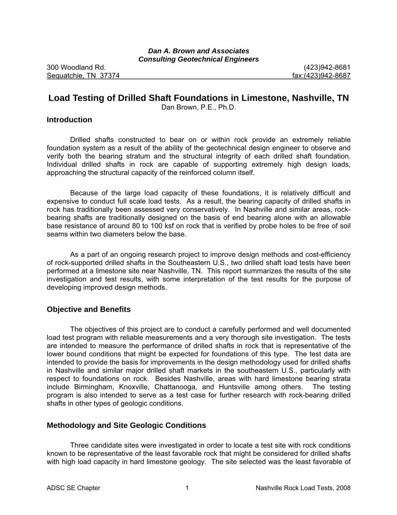
known to be representative of the least favorable rock that might be considered for drilled shafts with high load capacity in hard limestone geology. The site selected was the least favorable of
ADSC SE Chapter 2 Nashville Rock Load Tests, 2008
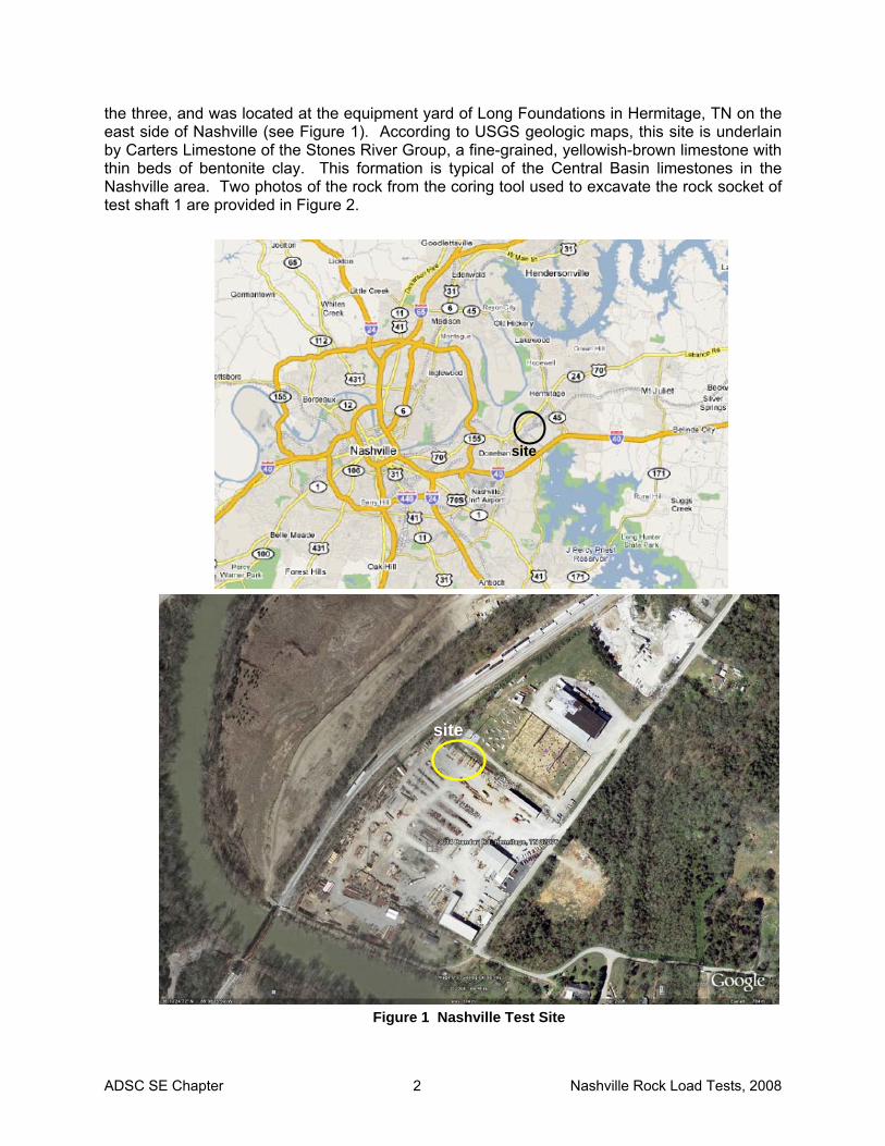
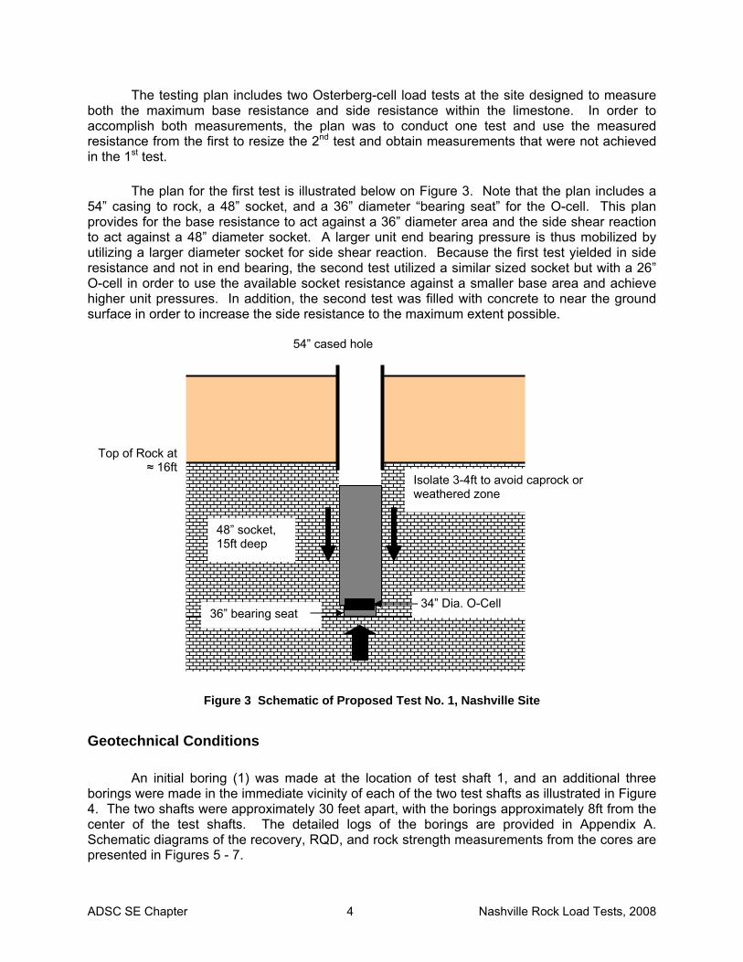
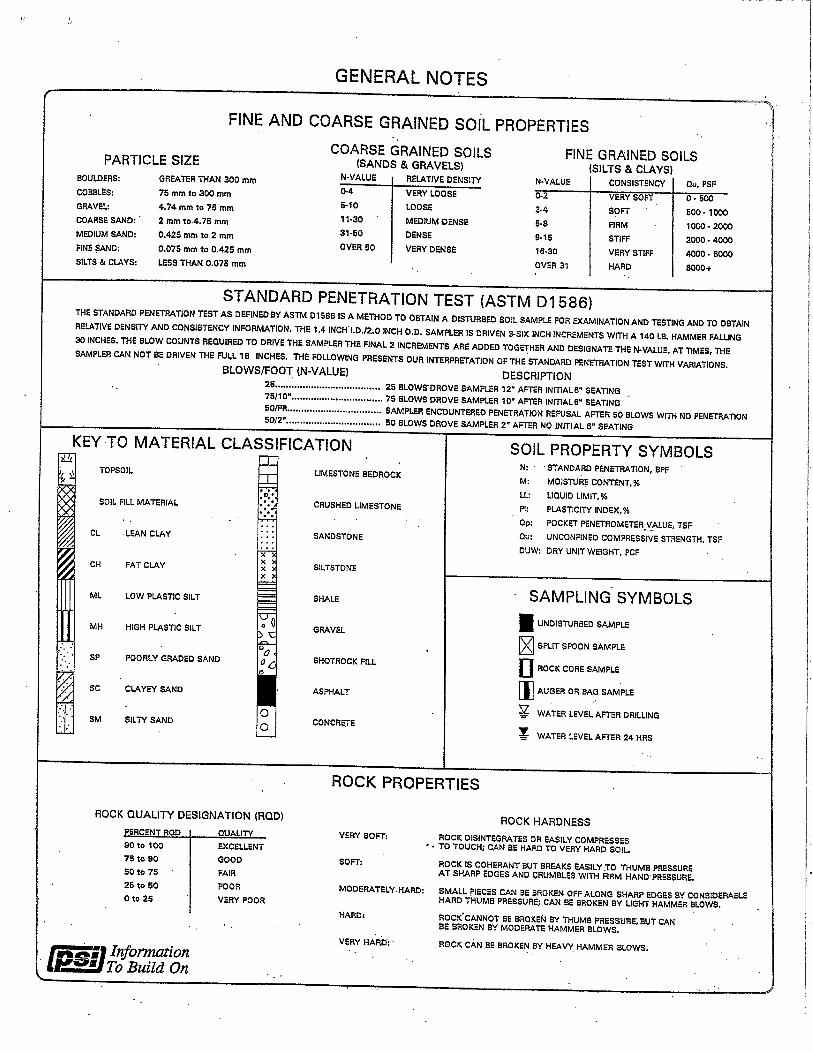
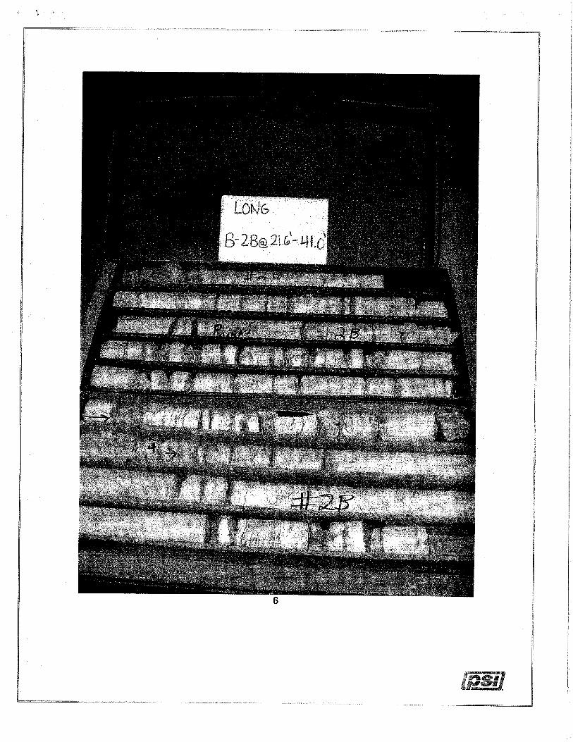
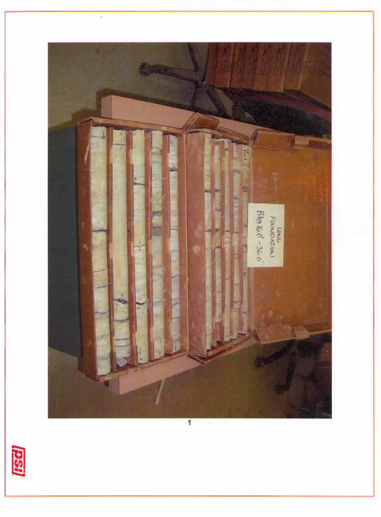
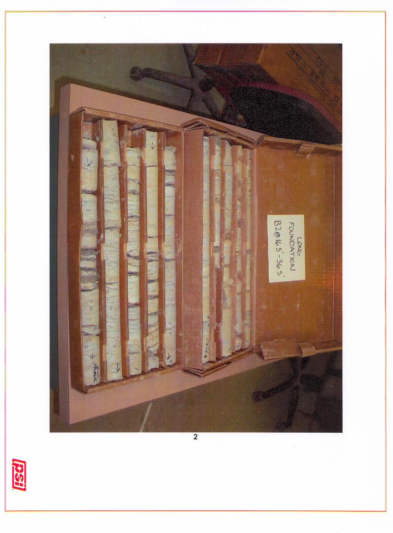
the three, and was located at the equipment yard of Long Foundations in Hermitage, TN on the east side of Nashville (see Figure 1). According to USGS geologic maps, this site is underlain by Carters Limestone of the Stones River Group, a fine-grained, yellowish-brown limestone with thin beds of bentonite clay. This formation is typical of the Central Basin limestones in the Nashville area. Two photos of the rock from the coring tool used to excavate the rock socket of test shaft 1 are provided in Figure 2.
Figure 1 Nashville Test Site
site
site
ADSC SE Chapter 3 Nashville Rock Load Tests, 2008
Figure 2 Rock from Coring Tool Used to Excavate Socket for Test Shaft 1
ADSC SE Chapter 4 Nashville Rock Load Tests, 2008
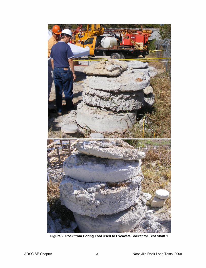
The testing plan includes two Osterberg-cell load tests at the site designed to measure both the maximum base resistance and side resistance within the limestone. In order to accomplish both measurements, the plan was to conduct one test and use the measured resistance from the first to resize the 2nd test and obtain measurements that were not achieved in the 1st test.
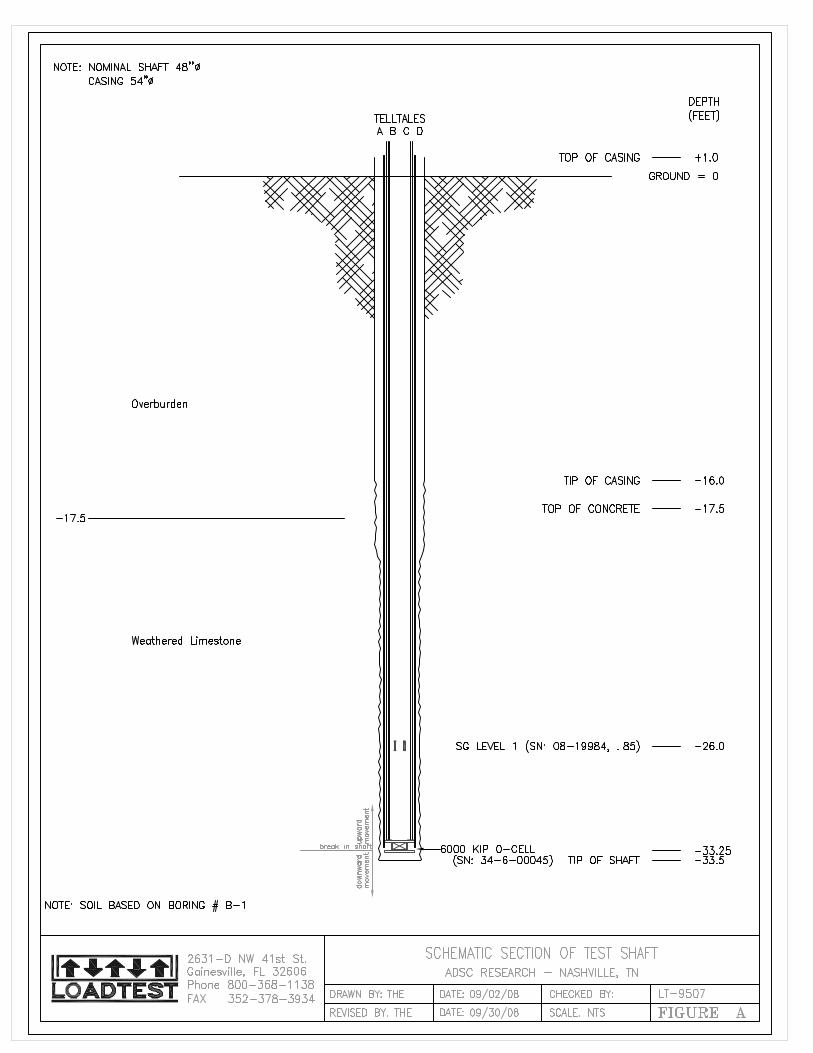
The plan for the first test is illustrated below on Figure 3. Note that the plan includes a
54” casing to rock, a 48” socket, and a 36” diameter “bearing seat” for the O-cell. This plan provides for the base resistance to act against a 36” diameter area and the side shear reaction to act against a 48” diameter socket. A larger unit end bearing pressure is thus mobilized by utilizing a larger diameter socket for side shear reaction. Because the first test yielded in side resistance and not in end bearing, the second test utilized a similar sized socket but with a 26” O-cell in order to use the available socket resistance against a smaller base area and achieve higher unit pressures. In addition, the second test was filled with concrete to near the ground surface in order to increase the side resistance to the maximum extent possible.
Figure 3 Schematic of Proposed Test No. 1, Nashville Site
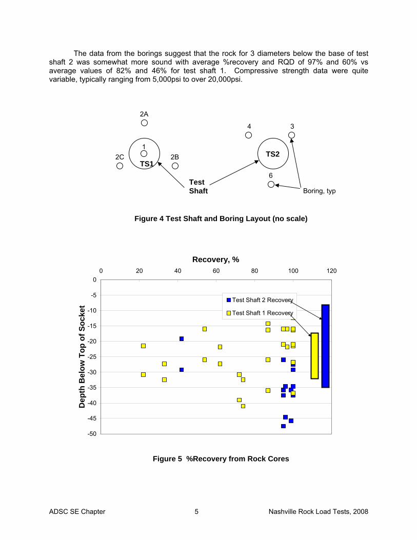
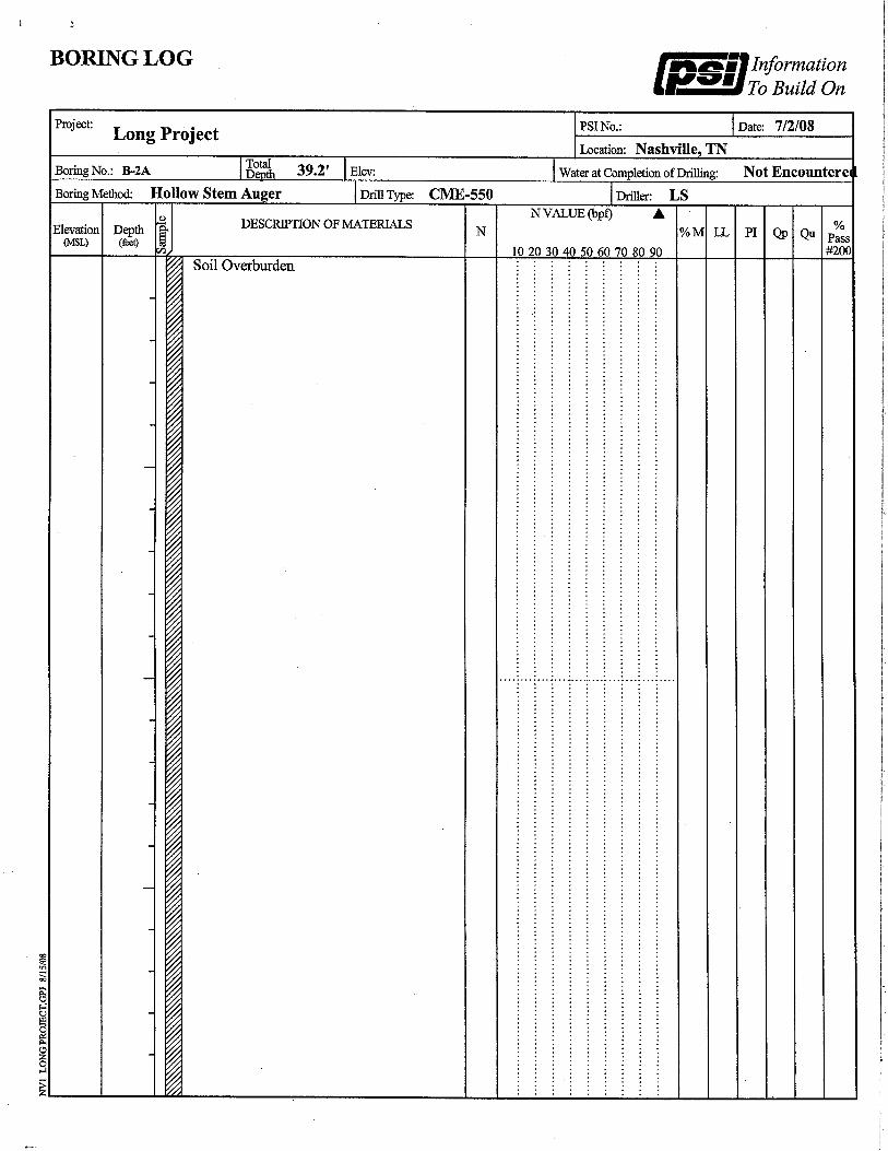
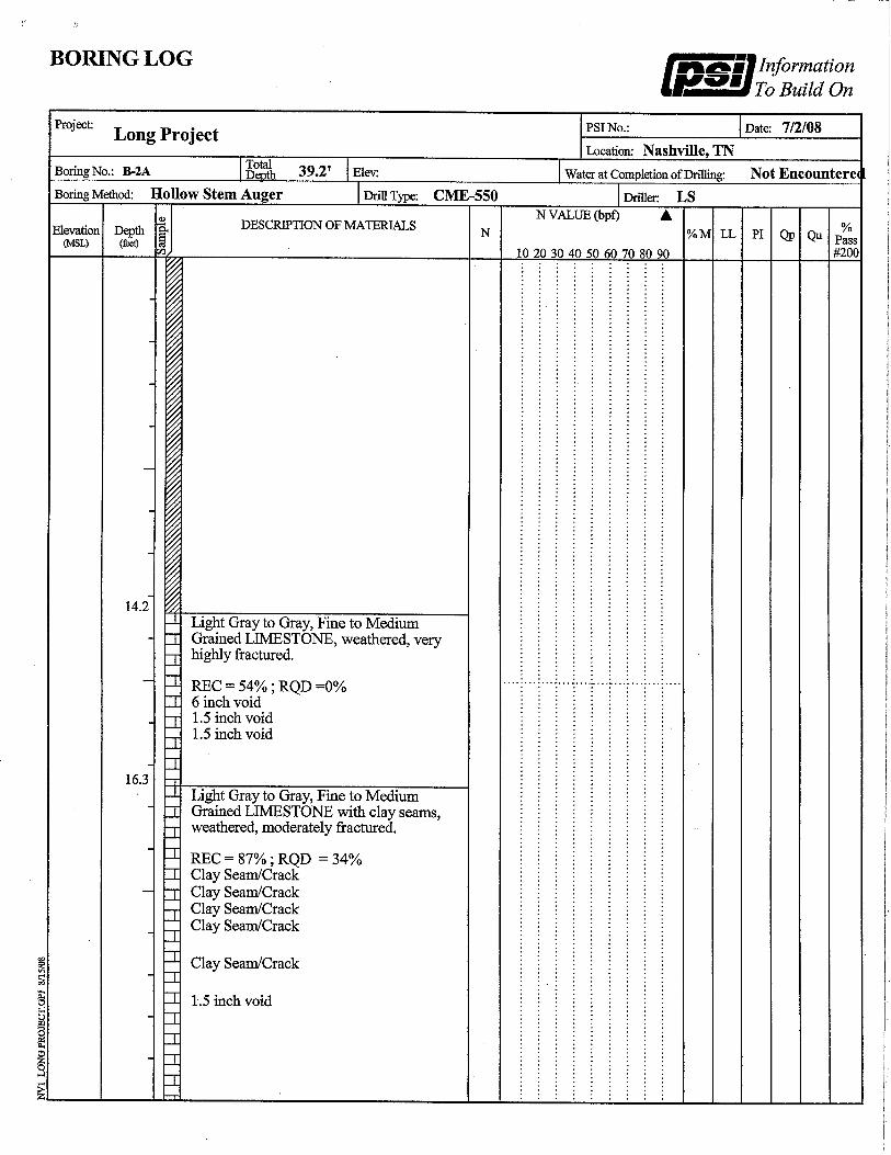
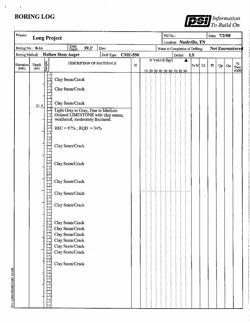
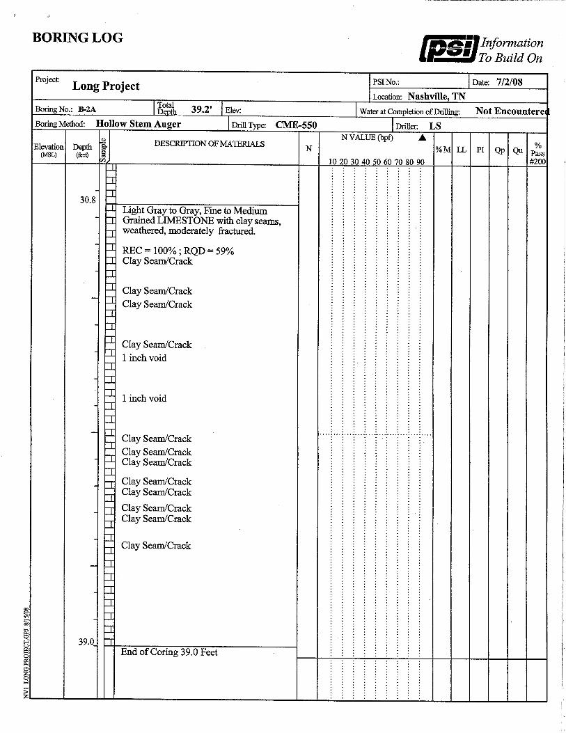
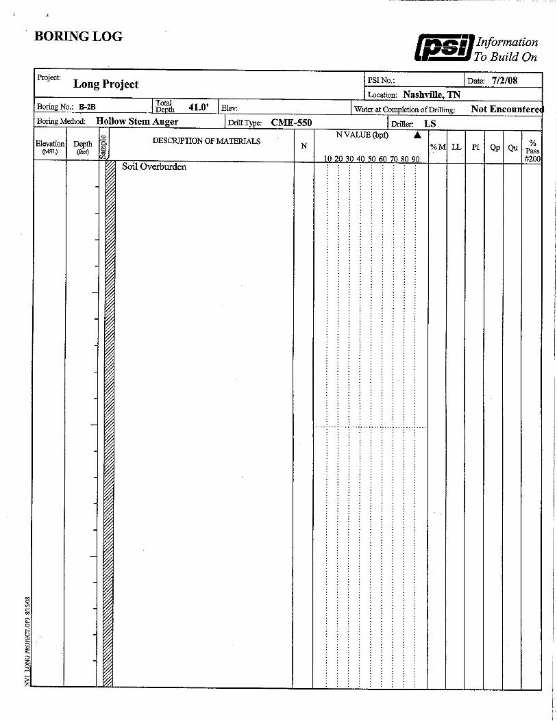
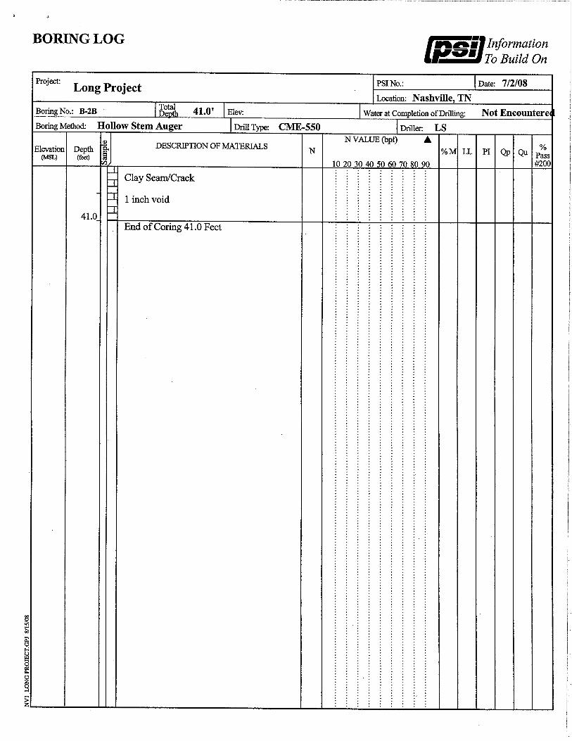
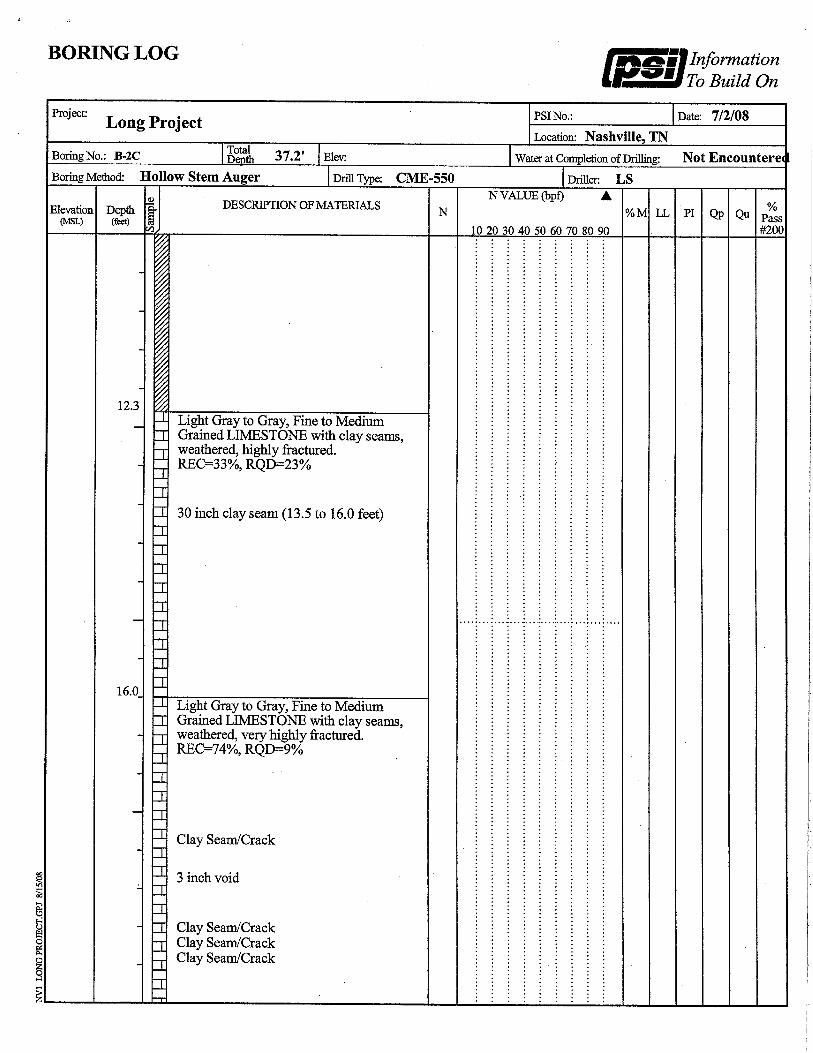
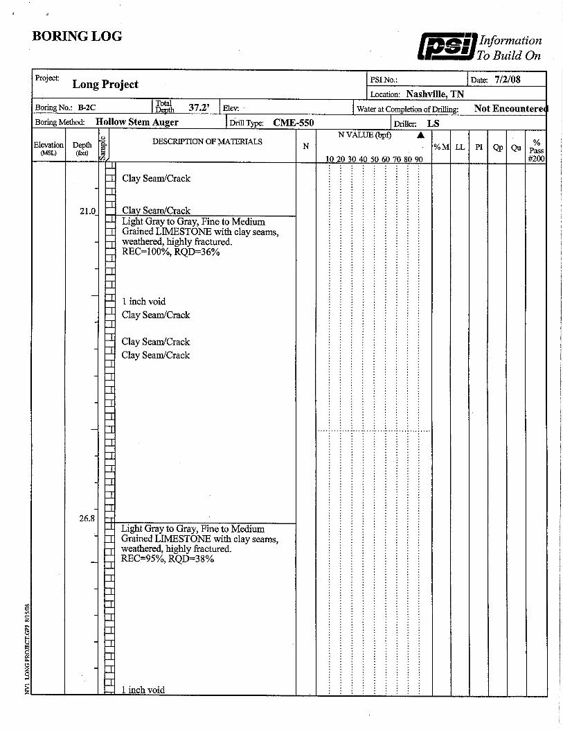
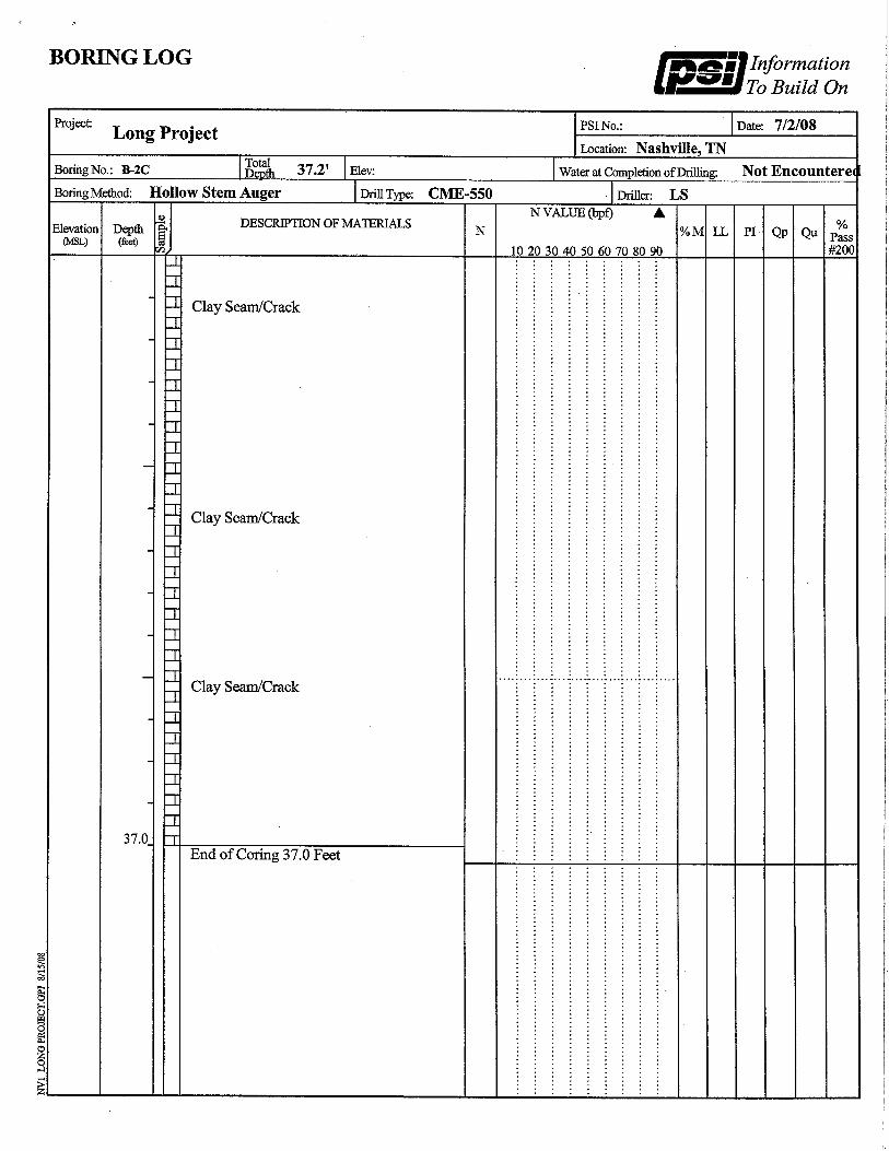
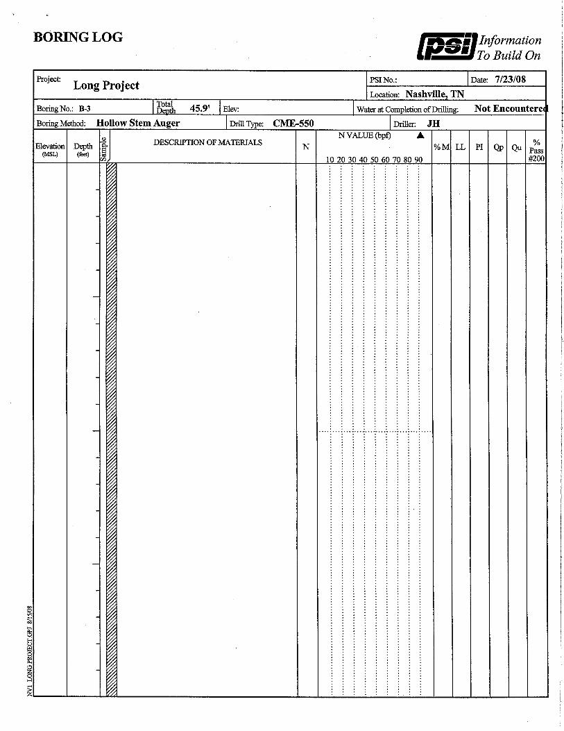
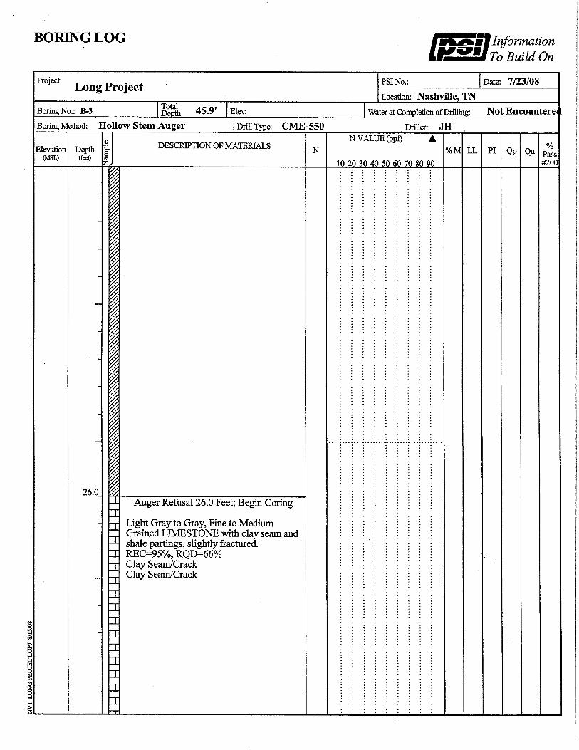
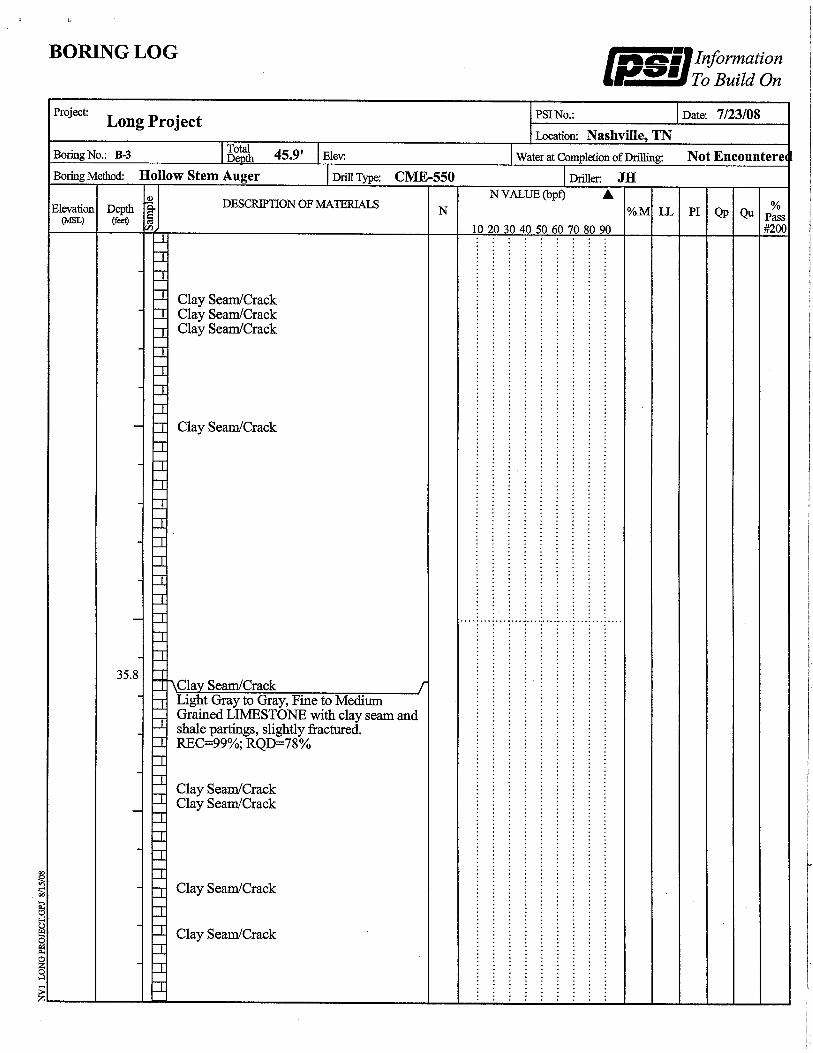
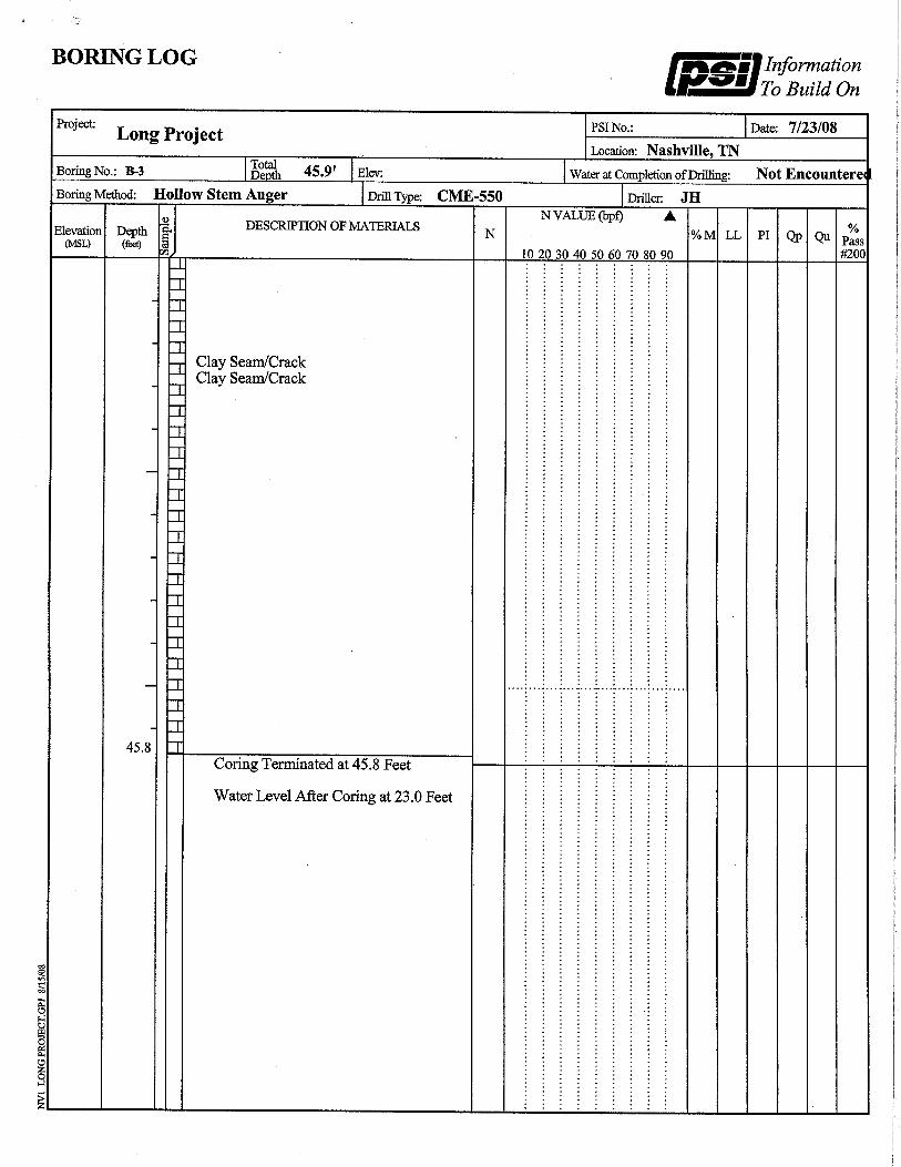
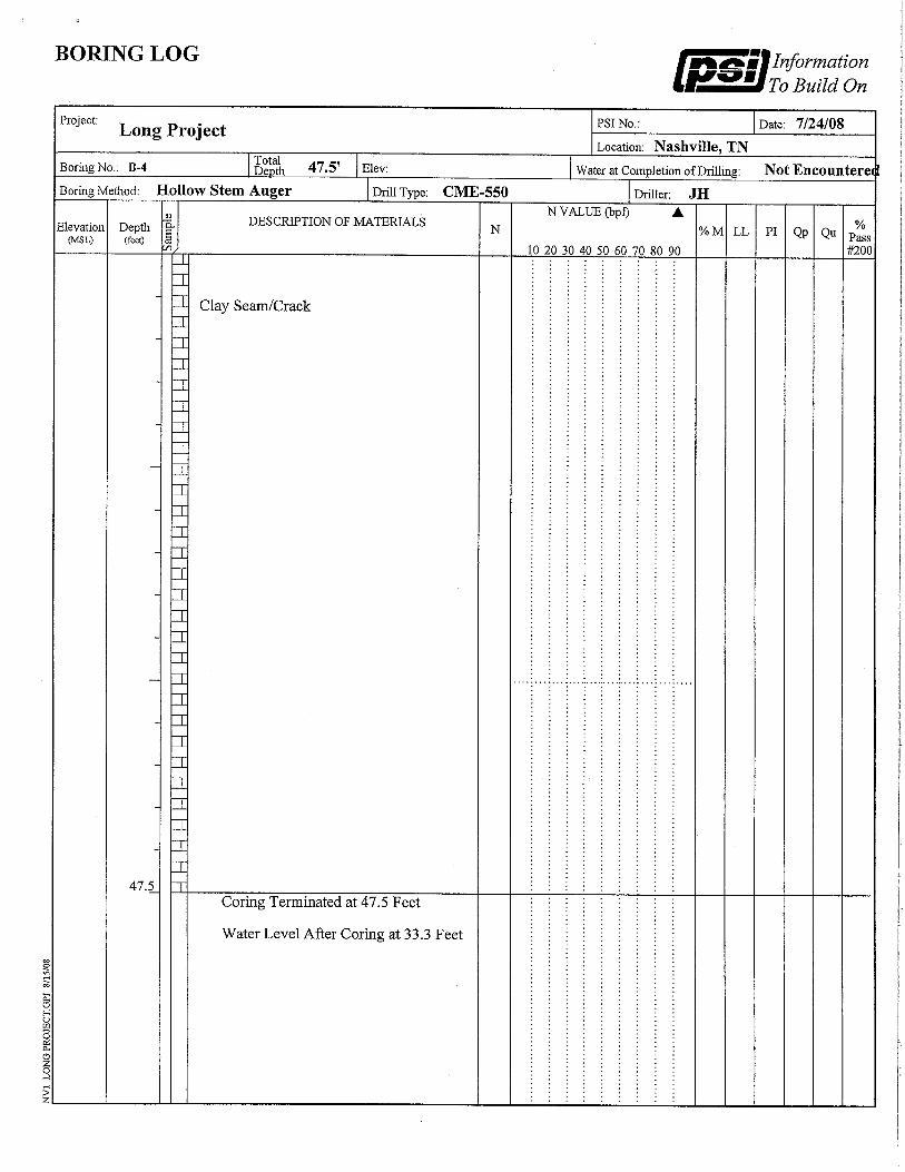
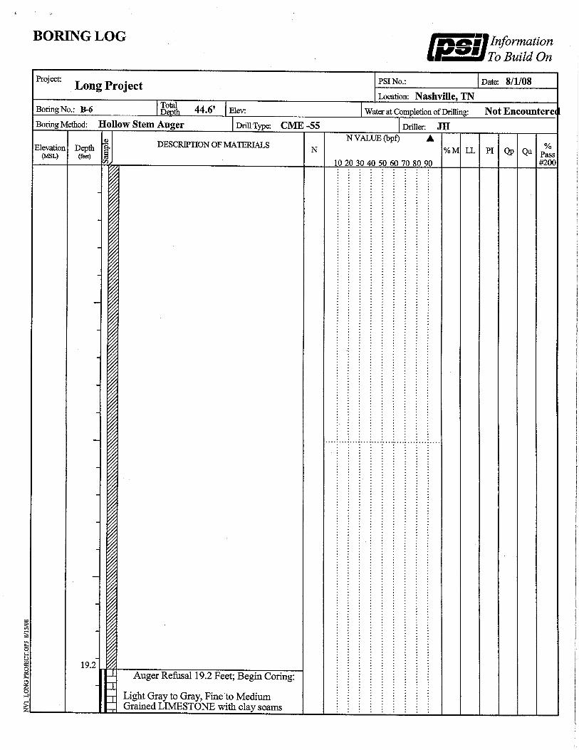
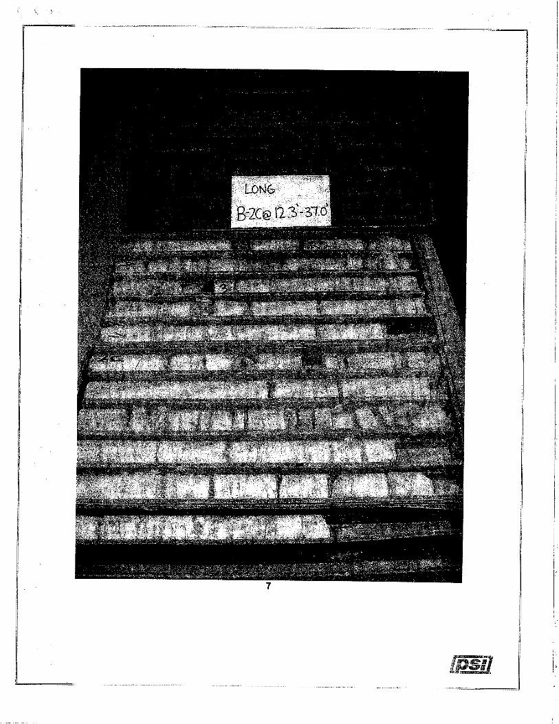
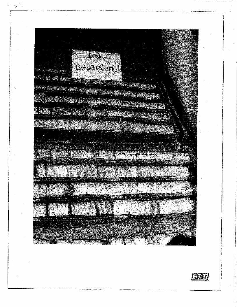
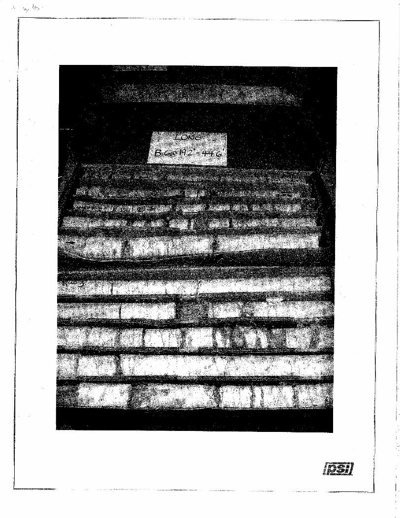
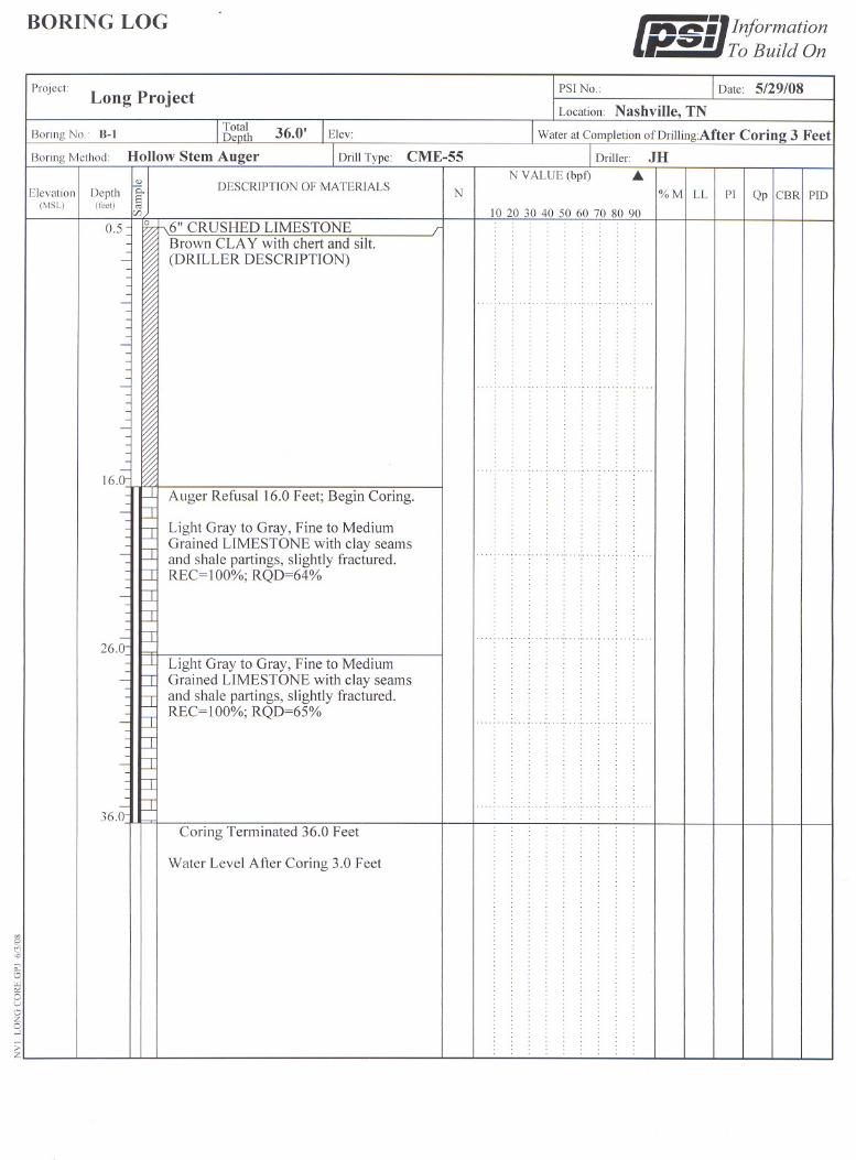
Geotechnical Conditions An initial boring (1) was made at the location of test shaft 1, and an additional three
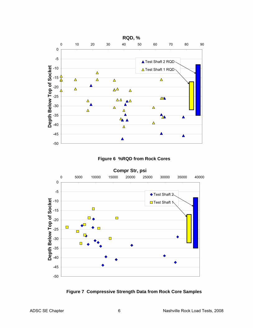
borings were made in the immediate vicinity of each of the two test shafts as illustrated in Figure 4. The two shafts were approximately 30 feet apart, with the borings approximately 8ft from the center of the test shafts. The detailed logs of the borings are provided in Appendix A. Schematic diagrams of the recovery, RQD, and rock strength measurements from the cores are presented in Figures 5 - 7.
54” cased hole
48” socket, 15ft deep
36” bearing seat
Top of Rock at ≈ 16ft
Isolate 3-4ft to avoid caprock or weathered zone
34” Dia. O-Cell
ADSC SE Chapter 5 Nashville Rock Load Tests, 2008
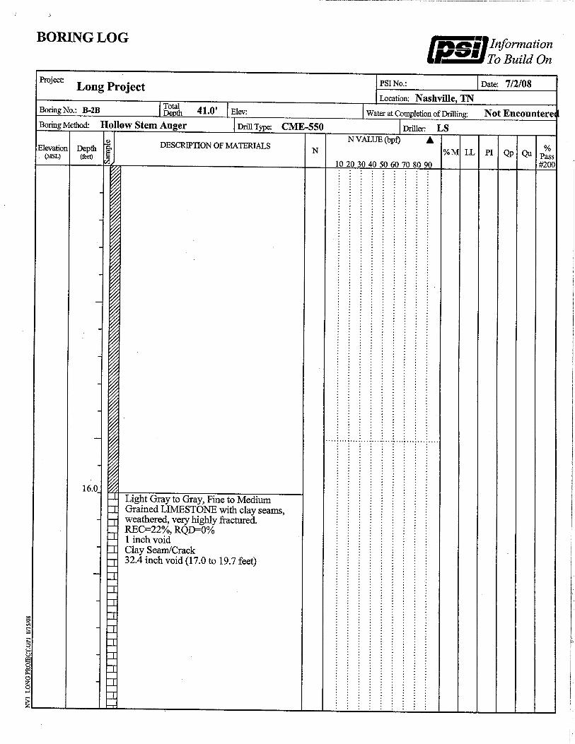
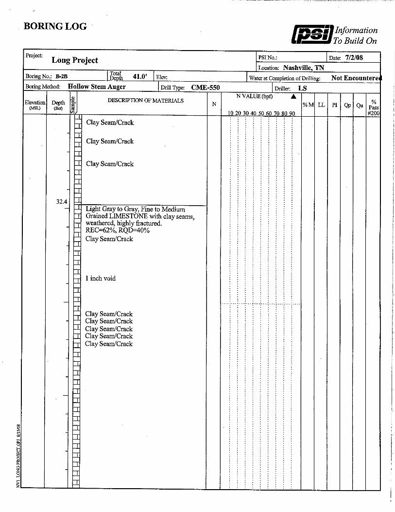
The data from the borings suggest that the rock for 3 diameters below the base of test shaft 2 was somewhat more sound with average %recovery and RQD of 97% and 60% vs average values of 82% and 46% for test shaft 1. Compressive strength data were quite variable, typically ranging from 5,000psi to over 20,000psi.
Figure 4 Test Shaft and Boring Layout (no scale)
-50
-45
-40
-35
-30
-25
-20
-15
-10
-5
00 20 40 60 80 100 120
Recovery, %
Dep
th B
elow
Top
of S
ocke
t
Test Shaft 2 Recovery
Test Shaft 1 Recovery
Figure 5 %Recovery from Rock Cores
TS1 TS2
2A
2B 2C
4 3
6
Boring, typ Test Shaft
1
ADSC SE Chapter 6 Nashville Rock Load Tests, 2008
-50
-45
-40
-35
-30
-25
-20
-15
-10
-5
00 10 20 30 40 50 60 70 80 90
RQD, %
Dep
th B
elow
Top
of S
ocke
t
Test Shaft 2 RQD
Test Shaft 1 RQD
Figure 6 %RQD from Rock Cores
-50
-45
-40
-35
-30
-25
-20
-15
-10
-5
00 5000 10000 15000 20000 25000 30000 35000 40000
Compr Str, psi
Dep
th B
elow
Top
of S
ocke
t
Test Shaft 2
Test Shaft 1
Figure 7 Compressive Strength Data from Rock Core Samples
ADSC SE Chapter 7 Nashville Rock Load Tests, 2008
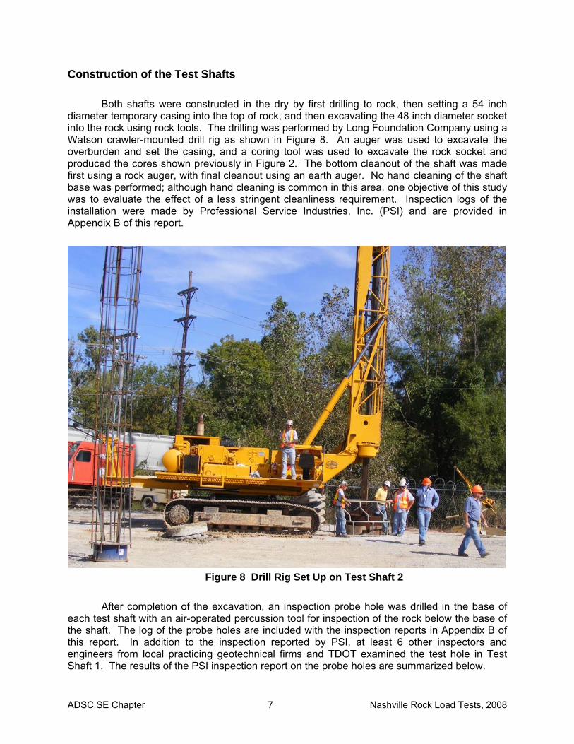
Construction of the Test Shafts Both shafts were constructed in the dry by first drilling to rock, then setting a 54 inch
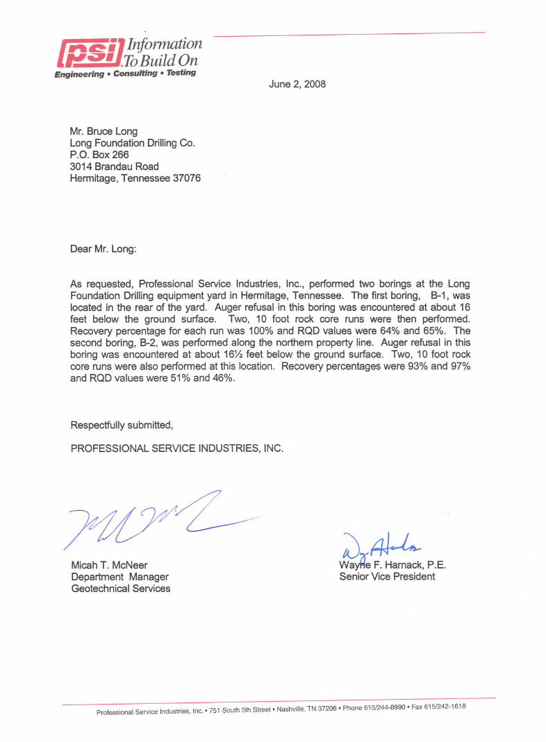
diameter temporary casing into the top of rock, and then excavating the 48 inch diameter socket into the rock using rock tools. The drilling was performed by Long Foundation Company using a Watson crawler-mounted drill rig as shown in Figure 8. An auger was used to excavate the overburden and set the casing, and a coring tool was used to excavate the rock socket and produced the cores shown previously in Figure 2. The bottom cleanout of the shaft was made first using a rock auger, with final cleanout using an earth auger. No hand cleaning of the shaft base was performed; although hand cleaning is common in this area, one objective of this study was to evaluate the effect of a less stringent cleanliness requirement. Inspection logs of the installation were made by Professional Service Industries, Inc. (PSI) and are provided in Appendix B of this report.
Figure 8 Drill Rig Set Up on Test Shaft 2
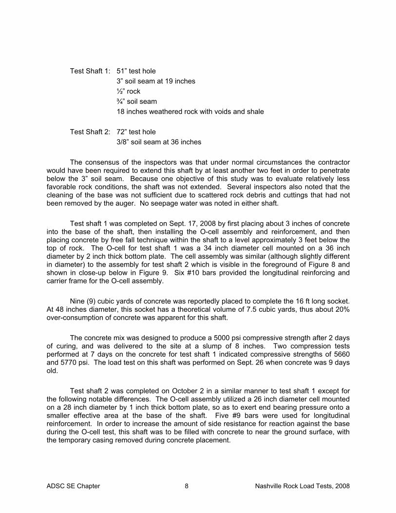
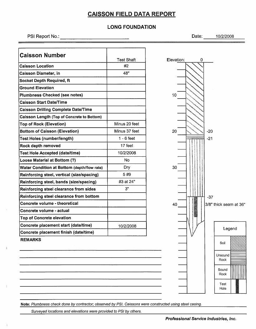
After completion of the excavation, an inspection probe hole was drilled in the base of
each test shaft with an air-operated percussion tool for inspection of the rock below the base of the shaft. The log of the probe holes are included with the inspection reports in Appendix B of this report. In addition to the inspection reported by PSI, at least 6 other inspectors and engineers from local practicing geotechnical firms and TDOT examined the test hole in Test Shaft 1. The results of the PSI inspection report on the probe holes are summarized below.
ADSC SE Chapter 8 Nashville Rock Load Tests, 2008
Test Shaft 1: 51” test hole 3” soil seam at 19 inches ½” rock ¾” soil seam 18 inches weathered rock with voids and shale
Test Shaft 2: 72” test hole 3/8” soil seam at 36 inches
The consensus of the inspectors was that under normal circumstances the contractor would have been required to extend this shaft by at least another two feet in order to penetrate below the 3” soil seam. Because one objective of this study was to evaluate relatively less favorable rock conditions, the shaft was not extended. Several inspectors also noted that the cleaning of the base was not sufficient due to scattered rock debris and cuttings that had not been removed by the auger. No seepage water was noted in either shaft.
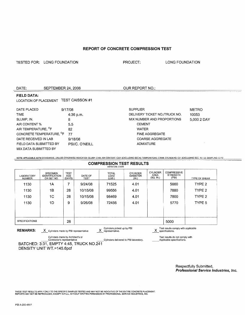
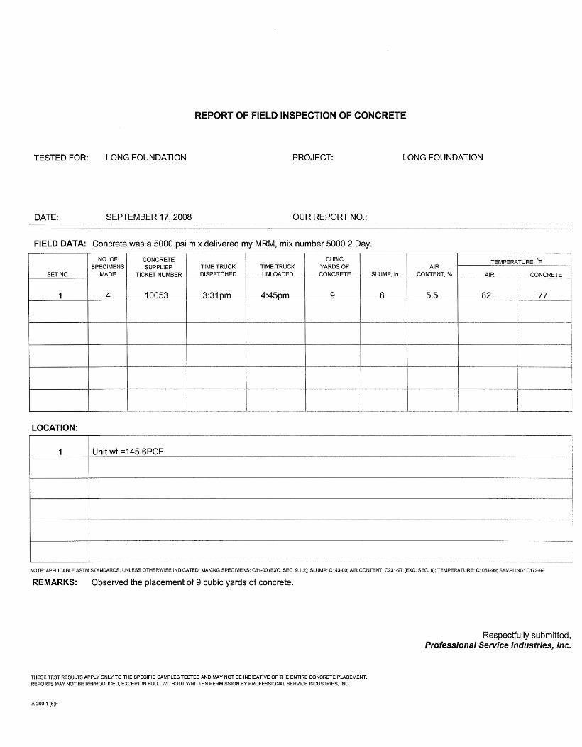
Test shaft 1 was completed on Sept. 17, 2008 by first placing about 3 inches of concrete
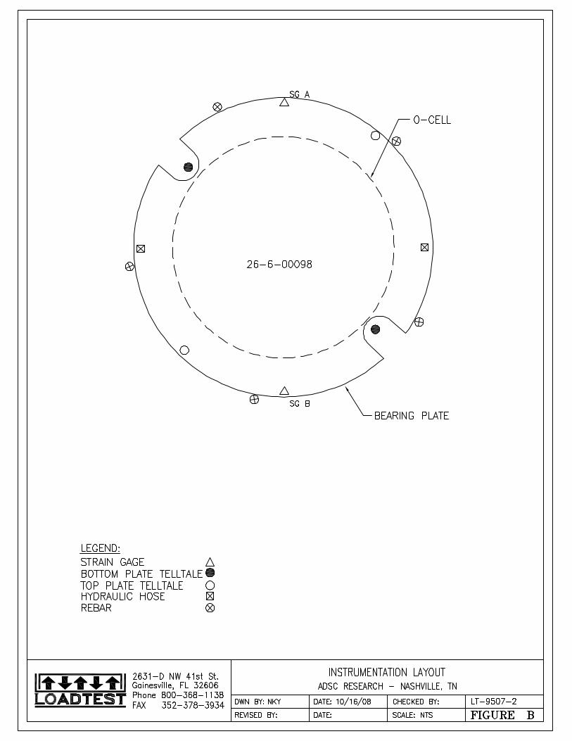
into the base of the shaft, then installing the O-cell assembly and reinforcement, and then placing concrete by free fall technique within the shaft to a level approximately 3 feet below the top of rock. The O-cell for test shaft 1 was a 34 inch diameter cell mounted on a 36 inch diameter by 2 inch thick bottom plate. The cell assembly was similar (although slightly different in diameter) to the assembly for test shaft 2 which is visible in the foreground of Figure 8 and shown in close-up below in Figure 9. Six #10 bars provided the longitudinal reinforcing and carrier frame for the O-cell assembly.
Nine (9) cubic yards of concrete was reportedly placed to complete the 16 ft long socket.
At 48 inches diameter, this socket has a theoretical volume of 7.5 cubic yards, thus about 20% over-consumption of concrete was apparent for this shaft.
The concrete mix was designed to produce a 5000 psi compressive strength after 2 days
of curing, and was delivered to the site at a slump of 8 inches. Two compression tests performed at 7 days on the concrete for test shaft 1 indicated compressive strengths of 5660 and 5770 psi. The load test on this shaft was performed on Sept. 26 when concrete was 9 days old.
Test shaft 2 was completed on October 2 in a similar manner to test shaft 1 except for
the following notable differences. The O-cell assembly utilized a 26 inch diameter cell mounted on a 28 inch diameter by 1 inch thick bottom plate, so as to exert end bearing pressure onto a smaller effective area at the base of the shaft. Five #9 bars were used for longitudinal reinforcement. In order to increase the amount of side resistance for reaction against the base during the O-cell test, this shaft was to be filled with concrete to near the ground surface, with the temporary casing removed during concrete placement.

ADSC SE Chapter 9 Nashville Rock Load Tests, 2008
Figure 9 Close-up of O-cell Assembly (Test Shaft 2)
Nine (9) cubic yards of concrete from the first load were placed and the level of concrete
was observed to fill the 17 ft length of socket and extend one foot into the 54 inch casing. The theoretical volume of concrete to achieve that elevation within the shaft was 8.5 cubic yards, thus an over-consumption of only about 5% was observed from the first load of concrete. However, an additional 11 cubic yards was placed within the casing and the level of concrete only increased by an additional 5 feet; the theoretical volume for this incremental increase in concrete elevation was only 3 cubic yards. Since the casing was still in place at the time, approximately 8 cubic yards of concrete was lost into a void somewhere below the bottom of the casing.
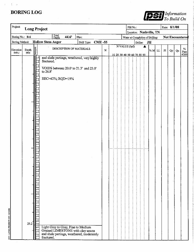
A review of the three borings around test shaft 2 suggests an explanation for the lost
concrete noted above. These 3 borings noted top of rock (auger refusal) at depths ranging from 19.2 feet to 27.5 feet, whereas the temporary casing was installed to a depth of 20 feet. The top of sound rock was therefore quite irregular in this location, and it is likely that the concrete blew out into a void near the top of rock or bottom of casing once a few feet of head inside the casing produced sufficient pressure.
The concrete mix was similar to that used for test shaft 1. At the time of the load test on
Oct. 14, 2008, a 12-day break on one cylinder indicated a compressive strength of 5900psi.
Load Test Results Load tests of test shafts 1 and 2 were conducted by Loadtest, Inc. under direction by the
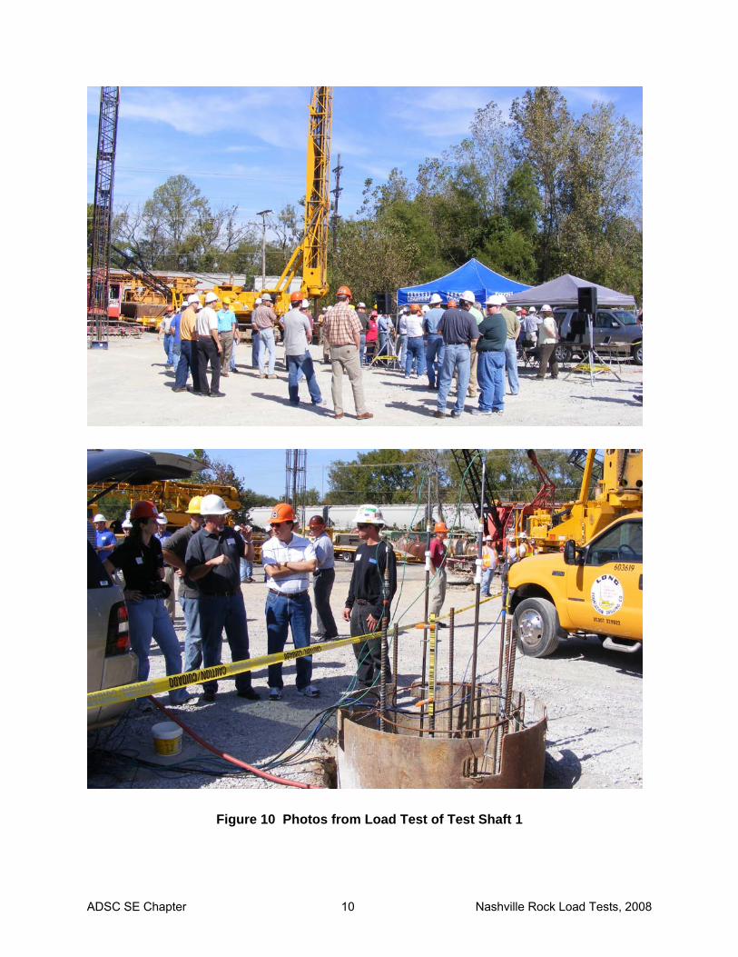
writer, with tests performed on Sept. 17, 2008 and Oct. 14, 2008, respectively. The first test was organized as a part of the local monthly ASCE lunchtime meeting and thus was witnessed by around 60 attendees (see photos in Figure 10). Detailed results of both load tests are presented in Appendix C and summarized below.
Bottom Plate
Tell-tale Rod
Carrier Frame (rebar cage)
O-cell
ADSC SE Chapter 10 Nashville Rock Load Tests, 2008
Figure 10 Photos from Load Test of Test Shaft 1

ADSC SE Chapter 11 Nashville Rock Load Tests, 2008
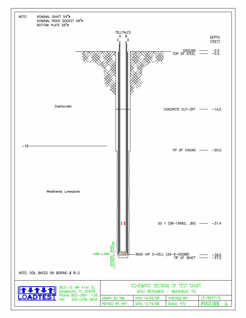
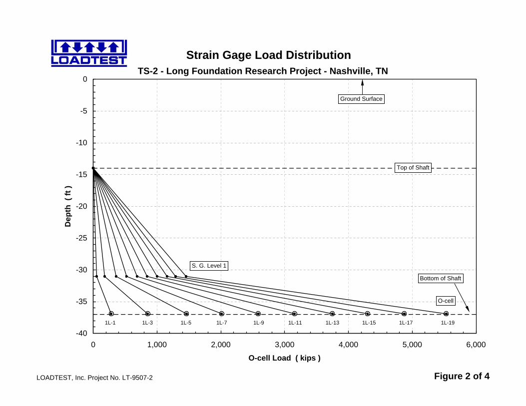
The final configuration of the two test shafts including the location of strain gauges are illustrated below in Figure 11.
Figure 11 Schematic Diagram of Test Shafts 1 & 2
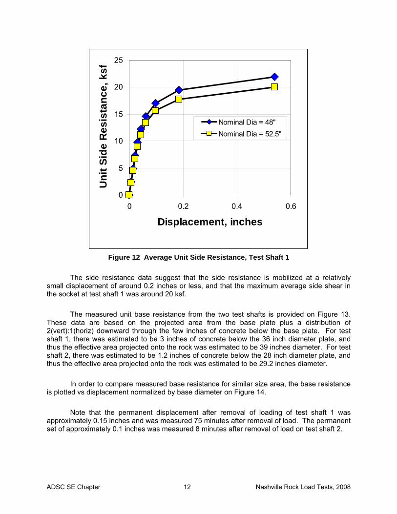
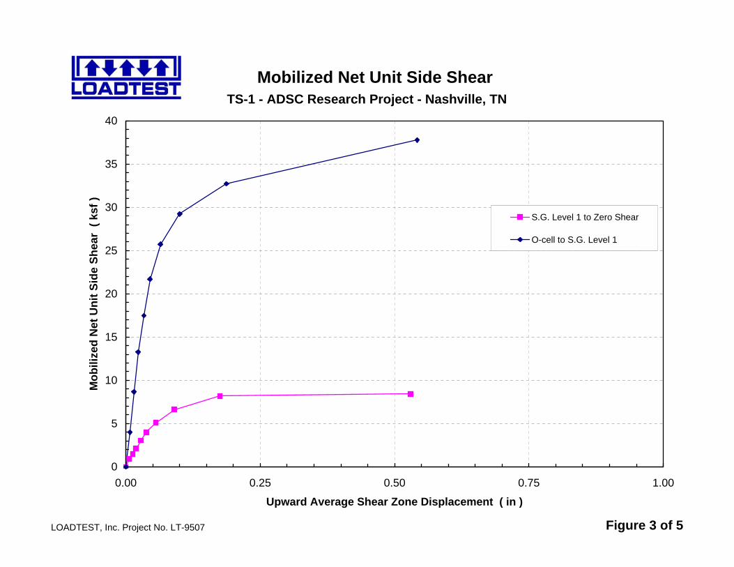
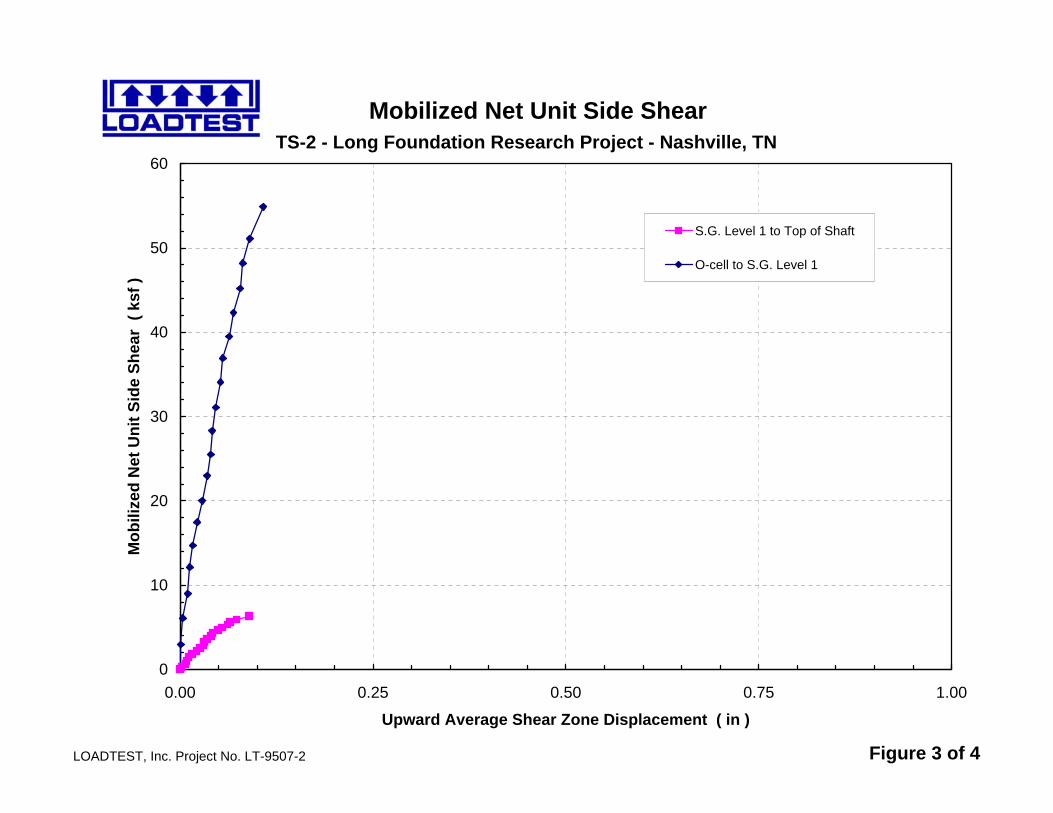
The overall side resistance in the rock was most reliably determined from the results of
test shaft 1, because this test was conducted to fully mobilize the shaft resistance and was not complicated by the large concrete over-run below the casing as occurred on test shaft 2. A graphical presentation of the average unit side resistance vs displacement for the socket of test shaft 1 is illustrated on Figure 12, with data plotted based on the nominal shaft diameter of 48 inches and on a shaft diameter adjusted for over-break based on the concrete volume.
The strain data suggest that larger side resistance was mobilized in the lower portion of
the socket. However, the actual distribution is subject to interpretation based on the strain gauges; there can be some uncertainty in the actual distribution of resistance compared to a top-down loading due to uncertainty in the actual modulus and area of the shaft at the exact location of the gauges and due to the upward directed loading. The interpretations of distribution of side resistance performed by Loadtest, Inc. based on the strain gauge data are included in Appendix C.
Ground Surface 0
Tip of Casing -16.0 Top of Conc -17.5
SG Level 1 -26.0
Tip of Shaft -33.5 Base of O-cell -33.25
Top of Conc -14.0
Tip of Casing -20.0
SG Level 1 -31.4
Base of O-cell -36.9 Tip of Shaft -37.0
Test Shaft 1 Test Shaft 2
ADSC SE Chapter 12 Nashville Rock Load Tests, 2008
0
5
10
15
20
25
0 0.2 0.4 0.6
Displacement, inches
Uni
t Sid
e R
esis
tanc
e, k
sf
Nominal Dia = 48"Nominal Dia = 52.5"
Figure 12 Average Unit Side Resistance, Test Shaft 1
The side resistance data suggest that the side resistance is mobilized at a relatively
small displacement of around 0.2 inches or less, and that the maximum average side shear in the socket at test shaft 1 was around 20 ksf.
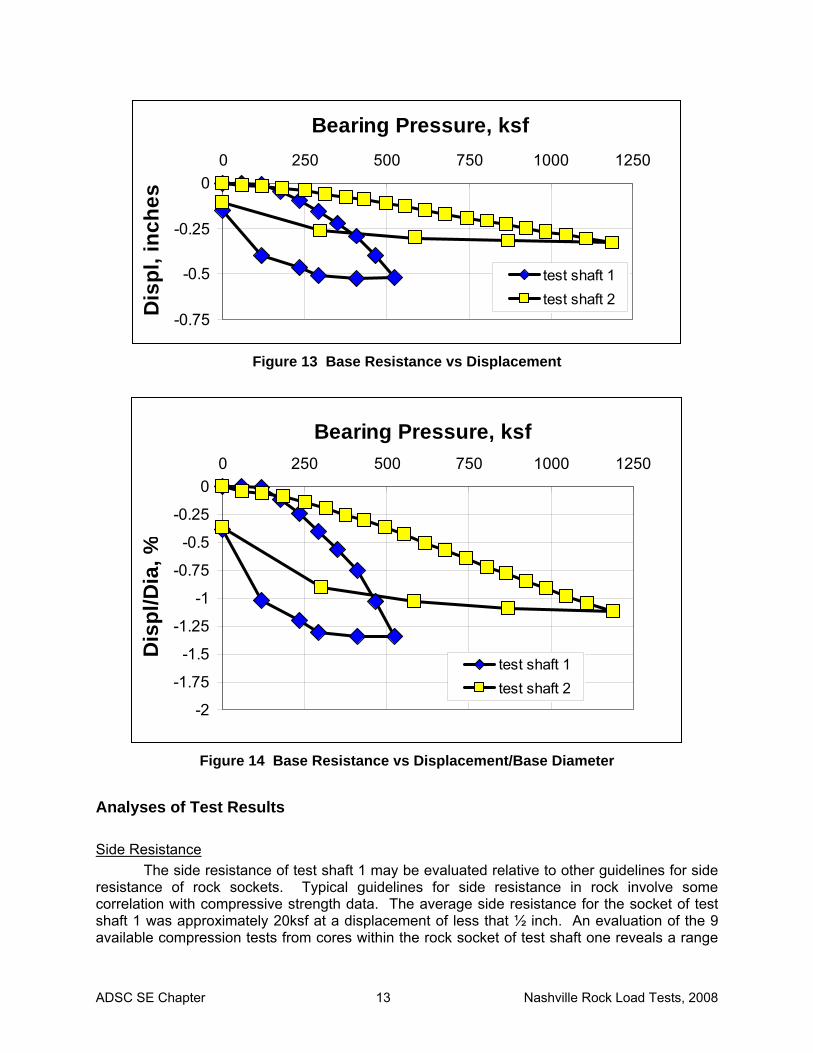
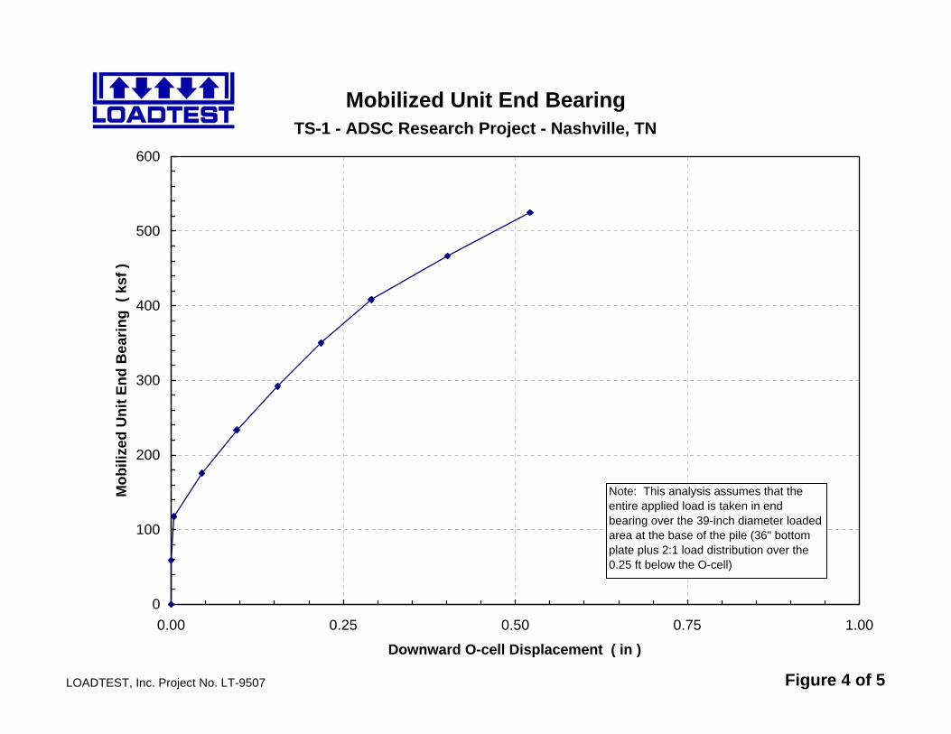
The measured unit base resistance from the two test shafts is provided on Figure 13.
These data are based on the projected area from the base plate plus a distribution of 2(vert):1(horiz) downward through the few inches of concrete below the base plate. For test shaft 1, there was estimated to be 3 inches of concrete below the 36 inch diameter plate, and thus the effective area projected onto the rock was estimated to be 39 inches diameter. For test shaft 2, there was estimated to be 1.2 inches of concrete below the 28 inch diameter plate, and thus the effective area projected onto the rock was estimated to be 29.2 inches diameter.
In order to compare measured base resistance for similar size area, the base resistance
is plotted vs displacement normalized by base diameter on Figure 14. Note that the permanent displacement after removal of loading of test shaft 1 was
approximately 0.15 inches and was measured 75 minutes after removal of load. The permanent set of approximately 0.1 inches was measured 8 minutes after removal of load on test shaft 2.
ADSC SE Chapter 13 Nashville Rock Load Tests, 2008
-0.75
-0.5
-0.25
00 250 500 750 1000 1250
Bearing Pressure, ksfD
ispl
, inc
hes
test shaft 1test shaft 2
Figure 13 Base Resistance vs Displacement
-2
-1.75
-1.5
-1.25
-1
-0.75
-0.5
-0.25
00 250 500 750 1000 1250
Bearing Pressure, ksf
Dis
pl/D
ia, %
test shaft 1test shaft 2
Figure 14 Base Resistance vs Displacement/Base Diameter
Analyses of Test Results
Side Resistance The side resistance of test shaft 1 may be evaluated relative to other guidelines for side
resistance of rock sockets. Typical guidelines for side resistance in rock involve some correlation with compressive strength data. The average side resistance for the socket of test shaft 1 was approximately 20ksf at a displacement of less that ½ inch. An evaluation of the 9 available compression tests from cores within the rock socket of test shaft one reveals a range
ADSC SE Chapter 14 Nashville Rock Load Tests, 2008
of values from 1,660psi to 16,110psi and a mean of 8,300psi. Eliminating the highest and lowest values provides a range of values from 4,750psi to 14,170psi with a mean of 8,150psi. Core recovery ranged from 74% to 100% and RQD ranged from 9% to 65%.
A typical expression used for unit side resistance, fs is one originally proposed by Rowe
and Armitage1 and subsequently modified by Kulhawy and Phoon2 as follows:
( )a
uas
pqpCf ⋅⋅= (1)
where qu is unconfined compressive strength, pa is atmospheric pressure, and C is an empirical constant ranging from 0.65 to as high as 3. Back-analysis of the test results using fs of 20ksf and qu of 8300psi suggests that an average C-coefficient for this limestone would be only 0.4, a relatively low value compared to other rock formations.
A possible explanation of the relatively low empirical constant may be that the clay-filled
seams tended to contaminate the surface of the limestone so that the relatively high strength of the rock is not mobilized in side shear. It is also the case that the low RQD suggests that a large portion of the rock within the socket may not have been represented by the high strength of the relatively few portions of the core which are available for testing. Base Resistance
The base resistance of the two shafts was mobilized up to relative displacements of just
over 1% of the diameter of the loaded area, but did not mobilize the geotechnical limit of the formation in terms of bearing capacity. For evaluation of the load vs deformation characteristics of the base resistance, it is appropriate to consider the settlement, ρs of a rigid circular loaded area bearing on the surface of an elastic half space, which may be expressed as follows:
( )E
qBs
2179.0 νρ −⋅= (2)
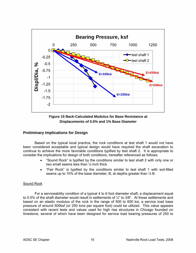
where q is the bearing pressure, ν is Poisson’s ratio, and E is the elastic modulus of the rock mass. For a typical value of Poisson’s ratio of 0.25, and values of ρs equal to 0.5% to 1% of the diameter of the base, the effective elastic modulus of the rock mass can be back-calculated from the load test data to derive the values shown on Figure 15.
The lower back-calculated value for test shaft 1 is undoubtedly related to the fact that
approximately 4 inches of soil was present at a depth of about 19 to 23 inches below the base of the 39 inch diameter loaded area. Normalized by the base diameter, B, this represents a soil seam of thickness equal to 10% of the base diameter and located at a distance of approximately ½ B.
1 Rowe, R.K. and H.H. Armitage, (1987). “A Design Method for Drilled Piers in Soft Rock,” Canadian Geotechnical Journal, Vol. 24, pp. 126-142. 2 Kulhawy, F.H. and K.K. Phoon, (1993). “Drilled Shaft Side Resistance in Clay Soil to Rock,” GSP38, ASCE pp. 172-183.
ADSC SE Chapter 15 Nashville Rock Load Tests, 2008
-2
-1.75
-1.5
-1.25
-1
-0.75
-0.5
-0.25
00 250 500 750 1000 1250
Bearing Pressure, ksfD
ispl
/Dia
, %
test shaft 1test shaft 2
E=536ksi
E=235ksi
E=630ksiE=335ksi
Figure 15 Back-Calculated Modulus for Base Resistance at
Displacements of 0.5% and 1% Base Diameter
Preliminary Implications for Design Based on the typical local practice, the rock conditions at test shaft 1 would not have
been considered acceptable and typical design would have required the shaft excavation to continue to achieve the more favorable conditions typified by test shaft 2. It is appropriate to consider the implications for design of both conditions, hereafter referenced as follows:
• “Sound Rock” is typified by the conditions similar to test shaft 2 with only one or two small seams less than ½ inch thick
• “Fair Rock” is typified by the conditions similar to test shaft 1 with soil-filled seams up to 10% of the base diameter, B, at depths greater than ½ B.
Sound Rock
For a serviceability condition of a typical 4 to 6 foot diameter shaft, a displacement equal
to 0.5% of the shaft diameter would result in settlements of ¼” to 3/8”. At these settlements and based on an elastic modulus of the rock in the range of 500 to 600 ksi, a service load base pressure of around 500ksf (or 250 tons per square foot) could be utilized. This value appears consistent with recent tests and values used for high rise structures in Chicago founded on limestone, several of which have been designed for service load bearing pressures of 250 to
ADSC SE Chapter 16 Nashville Rock Load Tests, 2008
300 tons per square foot3. Measurements of post-construction settlements on the recently completed Trump Tower and other similar structures have confirmed that the use of these values produces settlements consistent with predictions.
At the values indicated above, a factor of safety of 2.5 would require that the rock
provide an ultimate bearing capacity of at least 1250ksf (625 tons per square foot). The load test of shaft 2 in the “Sound Rock” conditions was observed to mobilize a bearing pressure of 1250ksf at a displacement slightly over 1% of the shaft diameter without any signs of bearing failure in the rock. It may be noted that this bearing pressure is approximately 8600psi and exceeds the compressive stress that likely could be placed on the column from a structural strength limit standpoint.
It is also concluded that such high bearing pressures may be constrained by structural
strength limitations at service loads such that higher than normal concrete strength may be required to fully utilize these bearing pressures. There would be little reason to include side resistance in the design of a rock-bearing shaft on Sound Rock, since little additional resistance would likely be realized and structural considerations will likely govern in any event.
For design of shafts at bearing pressures approaching the values noted above, it is
expected that the following geotechnical and inspection requirements must be met: • A thorough geotechnical site investigation is required with rock coring and
compressive strength testing of the rock bearing formation. • Rock compressive strengths in the bearing formation should be in the 10,000 psi
range or higher and % recovery should typically exceed 90%. • The site investigation should reveal that no significant solution cavities exist
within the bearing formation below the anticipate bearing elevation. • The shafts must be completed in the dry, with down-hole inspection. • A down-hole probe to a depth of at least 2 shaft base diameters would be
conducted and inspected by a qualified geotechnical engineer on each shaft. • No more than two significant seams within the rock within two base diameters
and none greater than ½ inch in thickness.
The design of drilled shaft foundations in the Nashville area using the above recommendations would represent a significant increase in bearing pressures over historical practice in the area. For the immediate future, it is recommended that large projects with designs based on these significantly higher values include a field load test for confirmation of design values. Fair Rock
For a serviceability condition of a typical 4 to 6 foot diameter shaft, a displacement equal
to 0.5% of the shaft diameter would result in settlements of ¼” to 3/8”. At these settlements and based on an elastic modulus of the rock in the range of 200 to 300 ksi, a service load base
3 Walton, W., (2008). “Caisson Load and Osterberg Testing in Chicago,” presentation made at the ADSC Drilled Shaft Seminar, Atlanta, Nov. 19, 2008.
ADSC SE Chapter 17 Nashville Rock Load Tests, 2008
pressure of around 200ksf (or 100 tons per square foot) could be utilized. At this value, a factor of safety of 2.5 would require that the rock provide an ultimate bearing capacity of at least 500ksf (250 tons per square foot). The load test of shaft 1 in the “Fair Rock” conditions was observed to mobilize a bearing pressure of 500ksf at a displacement slightly over 1% of the shaft diameter without any signs of bearing failure in the rock.
For design of shafts at bearing pressures associated with the “Fair Rock” conditions
described above, it is expected that the following geotechnical and inspection requirements must be met:
• A thorough geotechnical site investigation is required with rock coring and compressive strength testing of the rock bearing formation.
• Rock compressive strengths in the bearing formation should be in the 5,000 psi range or higher and % recovery should typically exceed 70%.
• The site investigation should reveal that no significant solution cavities exist within the bearing formation below the anticipate bearing elevation.
• Inspection of the shaft excavation and rock materials brought from the hole with the drilling tools should confirm that the general character of the bearing stratum is consistent with the borings and with the design conditions.
Side Resistance
It may be prudent to consider the addition of side resistance to the end bearing used in
the design in “Fair Rock” conditions, particularly where 10 or more feet of socket length is required to achieve the required base resistance consistent with this condition. Note that the conditions through which the two rock sockets were constructed did not consist of rock that would qualify for the “Fair Rock” condition noted for base resistance above. The rock through which the side resistance was measured was characterized by relatively low % recovery and RQD, many seams, and highly variable compressive strengths.
For side resistance, the resistance is mobilized at small displacements and the
maximum value used in design is based upon a geotechnical strength condition. For design based on the conditions measured at the Nashville site, the recommended approach is to compute the nominal (limit) side resistance using the equation cited previously:
( )a
uas
pqpCf ⋅⋅= (1)
where qu is unconfined compressive strength, pa is atmospheric pressure, and C is an empirical constant taken to be equal to 0.4, for limestone similar to the Nashville test site. The recovery from cores in the rock at test shaft 1 averaged 85% and ranged from 20% to 100% with RQD averaging 38% and ranging from 0 to 65%.
For service load conditions, the allowable side resistance may be computed using the
nominal side resistance computed above divided by a factor of safety of 2.5. The allowable unit side resistance times the surface area of the rock socket may be added to the allowable base resistance to size the shaft for service loads.
ADSC SE Chapter 18 Nashville Rock Load Tests, 2008
It may be noted that the design based on allowable side and base resistance values will result in a greater proportion of the service load supported in side resistance because this resistance is mobilized at smaller displacements than the base. However, since the side resistance was observed to be ductile up to displacements in excess of ½ inch, the overall factor of safety will not be significantly affected by issues of strain compatibility.
Cost Implications of Improved Design in Rock Numerous drilled shaft designs have been completed over the years using base
resistance alone and an allowable (service load) design of 100ksf or less. It is reasonable to consider several hypothetical example cases to evaluate the potential cost benefit of improved design. Based on typical current practice in the area, in-place costs of drilled shaft foundations including excavation, concrete, and typical reinforcement is estimated at approximately $400 per cubic yard in earth, $1700 per cubic yard in rock.
Example 1 - Heavy Building
Hypothetical example 1 includes a heavy building structure with 50 drilled shafts to
support service loads of 3400 kips per shaft. The site is underlain by approximately 20 feet of overburden soils followed by 8 feet of weathered rock, 8 feet of rock meeting the characteristics described previously for “Fair Rock” and underlain by rock meeting the requirements for “Strong Rock”. Four designs are to be evaluated for cost implications:
A. Previous practice, based on rock excavation to “Strong Rock” and end bearing
alone at an allowable base resistance of 100ksf. B. “Strong Rock” base resistance as outlined in this report. C. “Fair Rock” base resistance as outlined in this report. D. “Fair Rock” base resistance plus side resistance as outlined in this report.
In each of the new designs (B, C, D) a load test is included for confirmation of the new
design values. Design A (previous practice) does not include costs for a load test shaft. For design A, the drilled shafts would be 7ft diameter at the base, and probably
excavated using an 8ft diameter casing through 20ft of soil overburden followed by 7ft diameter rock socket extending 16ft into the rock. Total costs would be:
• $15,000 per shaft for earth • $39,000 per shaft for rock • 50 shafts @ $54k/shaft = $2,700,000.
For design B, the drilled shafts could be 3ft diameter, although the structural bearing
stresses at service loads would be around 3300psi and high strength concrete might be required. With design of the shafts for a 3.5ft diameter base, stresses in the lower portion of the shaft would be less than 2500psi and a maximum bearing stress on “Strong Rock” would be approximately 350ksf. The 3.5ft diameter by 16ft long socket would likely include a 4ft diameter shaft through the overburden soils. Total costs would be:
ADSC SE Chapter 19 Nashville Rock Load Tests, 2008
• $3,750 per shaft for earth • $9,700 per shaft for rock • One load test shaft at a total cost of $75,000. • 50 shafts @ $13,500 + $75k load test = $750,000.
For design C, the drilled shafts could be founded on the “Fair Rock” with a socket
extending 8 feet below top of rock. These shafts could be 5ft diameter, with a service load bearing pressure of 175ksf. The 5ft diameter by 8ft long socket would likely include a 5.5ft diameter shaft through the overburden soils. Total costs would be:
• $7,000 per shaft for earth • $10,000 per shaft for rock • One load test shaft at a total cost of $75,000 • 50 shafts @ $17,000/shaft + $75k load test = $925,000.
For design D, the drilled shafts would be founded as for case C, but the side resistance
of the socket is included. With a maximum side resistance of 20ksf as measured in test shaft 1 and a factor of safety of 2.5, an allowable unit side resistance of 8ksf would be realized. As a result, a 4.5ft diameter by 8ft long socket could mobilize 900 kips of resistance against service loads resulting in a service load demand to the base of 2500 kips and a bearing pressure of 160ksf on the 4.5ft diameter base. The 4.5ft diameter by 8ft long socket would likely include a 5ft diameter shaft through the overburden soils. Total costs would be:
• $6,000 per shaft for earth • $8,000 per shaft for rock • One load test shaft at a total cost of $75,000. • 50 shafts @ $14,000/shaft + $75k load test = $775,000.
In summary, the estimated foundation costs for the four designs are: A. Previous practice, $2,700,000. B. “Strong Rock” base resistance, $750,000. C. “Fair Rock” base resistance, $925,000. D. “Fair Rock” base plus side resistance, $775,000. It appears that costs are essentially similar for B and D. Either represent a potential
savings of nearly $2million on the project compared to previous practice.
Example 2 - Large Structure with Less Concentrated Loads Hypothetical example 2 includes a large building structure with 150 drilled shafts to
support service loads of 1700 kips per shaft. The site is underlain by the same conditions as example 1, approximately 20 feet of overburden soils followed by 8 feet of weathered rock, 8 feet of rock meeting the characteristics described previously for “Fair Rock” and underlain by
ADSC SE Chapter 20 Nashville Rock Load Tests, 2008
rock meeting the requirements for “Strong Rock”. Four designs are to be evaluated for cost implications:
A. Previous practice, based on rock excavation to “Strong Rock” and end bearing
alone at an allowable base resistance of 100ksf. B. “Strong Rock” base resistance as outlined in this report. C. “Fair Rock” base resistance as outlined in this report. D. “Fair Rock” base resistance plus side resistance as outlined in this report. In each of the new designs (B, C, D) a load test is included for confirmation of the new
design values. Design A (previous practice) does not include costs for a load test shaft. For design A, the drilled shafts would be 5ft diameter at the base, and probably
excavated using an 5.5ft diameter casing through 20ft of soil overburden followed by 5ft diameter rock socket extending 16ft into the rock. Total costs would be:
• $7,000 per shaft for earth • $20,000 per shaft for rock • 150 shafts @ $27k/shaft = $4,050,000.
For design B, the drilled shafts could be 3ft diameter, which is the practical minimum for
downhole inspection. With design of the shafts for a 3ft diameter base, stresses in the lower portion of the shaft would be less than 1700psi and a maximum bearing stress on “Strong Rock” would be approximately 240ksf. The 3ft diameter by 16ft long socket would likely include a 3.5ft diameter shaft through the overburden soils. Total costs would be:
• $2,900 per shaft for earth • $7,100 per shaft for rock • One load test shaft at a total cost of $75,000. • 150 shafts @ $10,000 + $75k load test = $1,575,000.
For design C, the drilled shafts could be founded on the “Fair Rock” with a socket
extending 8 feet below top of rock. These shafts could be 3.5ft diameter, with a service load bearing pressure of 180ksf. The 3.5ft diameter by 8ft long socket would likely include a 4ft diameter shaft through the overburden soils. Total costs would be:
• $3,800 per shaft for earth • $4,900 per shaft for rock • One load test shaft at a total cost of $75,000 • 150 shafts @ $8,700/shaft + $75k load test = $1,380,000.
For design D, the drilled shafts would be founded as for case C, but the side resistance
of the socket is included. With a maximum side resistance of 20ksf as measured in test shaft 1 and a factor of safety of 2.5, an allowable unit side resistance of 8ksf would be realized. As a result, a 3ft diameter by 8ft long socket could mobilize 600 kips of resistance against service loads resulting in a service load demand to the base of 1100 kips and a bearing pressure of
ADSC SE Chapter 21 Nashville Rock Load Tests, 2008
160ksf on the 3ft diameter base. The 3ft diameter by 8ft long socket would likely include a 3.5ft diameter shaft through the overburden soils. Total costs would be:
• $2,900 per shaft for earth • $3,600 per shaft for rock • One load test shaft at a total cost of $75,000. • 150 shafts @ $6,500/shaft + $75k load test = $1,050,000.
In summary, the estimated foundation costs for the four designs are:
A. Previous practice, $4,050,000. B. “Strong Rock” base resistance, $1,575,000. C. “Fair Rock” base resistance, $1,380,000. D. “Fair Rock” base plus side resistance, $1,050,000.
It appears that costs clearly favor approach D. The benefits of extremely high base
resistance are not realized at the lesser load demands per shaft on this site. The key to savings is the reduced rock excavation and increased productivity associated with the shorter socket length because of the less stringent acceptance criterion. Even with including the cost of a load test, this approach represents a potential savings of $3million on the project at a cost approximately ¼ that of previous practice.
Example 3 - Medium Structure with Moderate Loads Hypothetical example 3 includes a building structure with 40 drilled shafts to support
service loads of 1000 kips per shaft. The site is underlain by the similar conditions as previous examples except the depth of weathered rock is less; the site has approximately 20 feet of overburden soils followed by 5 feet of weathered rock, 5 feet of rock meeting the characteristics described previously for “Fair Rock” and underlain by rock meeting the requirements for “Strong Rock”. Four designs are to be evaluated for cost implications:
A. Previous practice, based on rock excavation to “Strong Rock” and end bearing
alone at an allowable base resistance of 100ksf. B. “Strong Rock” base resistance as outlined in this report. C. “Fair Rock” base resistance as outlined in this report. D. “Fair Rock” base resistance plus side resistance as outlined in this report.
In each of the new designs (B, C, D) a load test is included for confirmation of the new
design values. Design A (previous practice) does not include costs for a load test shaft. For design A, the drilled shafts would be 4ft diameter at the base, and probably
excavated using an 4.5ft diameter casing through 20ft of soil overburden followed by 4ft diameter rock socket extending 10ft into the rock. Total costs would be:
ADSC SE Chapter 22 Nashville Rock Load Tests, 2008
• $4,700 per shaft for earth • $8,000 per shaft for rock • 40 shafts @ $12,700/shaft = $508,000.
For design B, the drilled shafts could be 3ft diameter, which is the practical minimum for
downhole inspection. With design of the shafts for a 3ft diameter base, stresses in the lower portion of the shaft would be less than 1000psi and a maximum bearing stress on “Strong Rock” would be approximately 150ksf. The 3ft diameter by 10ft long socket would likely include a 3.5ft diameter shaft through the overburden soils. Total costs would be:
• $2,900 per shaft for earth • $4,500 per shaft for rock • One load test shaft at a total cost of $75,000. • 40 shafts @ $7,400 + $75k load test = $371,000.
For design C, the drilled shafts could be founded on the “Fair Rock” with a socket
extending 5 feet below top of rock. These shafts could be 3ft diameter, with a service load bearing pressure of 150ksf, same as design B. The 3ft diameter by 8ft long socket would likely include a 3.5ft diameter shaft through the overburden soils. Total costs would be:
• $2,900 per shaft for earth • $2,300 per shaft for rock • One load test shaft at a total cost of $75,000 • 40 shafts @ $5,200/shaft + $75k load test = $283,000.
For design D, the drilled shafts would be founded as for case C, but the side resistance
of the socket is included. With a maximum side resistance of 20ksf as measured in test shaft 1 and a factor of safety of 2.5, an allowable unit side resistance of 8ksf would be realized. As a result, a 2.5ft diameter by 5ft long socket could mobilize 300 kips of resistance against service loads resulting in a service load demand to the base of 700 kips and a bearing pressure of 150ksf on the 2.5ft diameter base. The 2.5ft diameter by 5ft long socket would likely include a 3ft diameter shaft through the overburden soils. Total costs would be:
• $2,100 per shaft for earth • $1,600 per shaft for rock • One load test shaft at a total cost of $75,000. • 40 shafts @ $3,700/shaft + $75k load test = $223,000.
In summary, the estimated foundation costs for the four designs are: A. Previous practice, $508,000. B. “Strong Rock” base resistance, $371,000. C. “Fair Rock” base resistance, $283,000. D. “Fair Rock” base plus side resistance, $223,000.
ADSC SE Chapter 23 Nashville Rock Load Tests, 2008
It appears that costs clearly favor approach D. Even with including the cost of a load test on this relatively small project, this approach represents a potential savings of over $250k on the project at a cost approximately ½ that of previous practice.
Summary and Conclusions A program of load testing has been performed at a site near Nashville with rock that is
representative of the limestone conditions in this area. The results demonstrate that high end bearing and side resistance is available from drilled shafts constructed in this formation, and higher design values than have historically been used can be readily achieved. Design guidelines are suggested which can accommodate a range of rock conditions and can provide more economical use of drilled shaft foundations. The guidelines require a thorough site investigation and inspection program. Load testing is recommended on future projects to confirm the successful use of this approach and validate the guidelines. Cost analyses of a range of hypothetical projects suggest that the new guidelines provide an opportunity for substantial cost savings, even with the inclusion of investments in site specific load testing.
ADSC SE Chapter 24 Nashville Rock Load Tests, 2008
Appendix A Site Investigation and Borings


ADSC SE Chapter 25 Nashville Rock Load Tests, 2008
Appendix B Inspection Records of Drilled Shaft Construction


ADSC SE Chapter 26 Nashville Rock Load Tests, 2008
Appendix C Load Test Reports
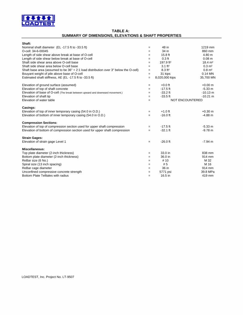
TABLE A: SUMMARY OF DIMENSIONS, ELEVATIONS & SHAFT PROPERTIES
Shaft:Nominal shaft diameter (EL -17.5 ft to -33.5 ft) = 48 in 1219 mmO-cell: 34-6-00045 = 34 in 860 mmLength of side shear above break at base of O-cell = 15.8 ft 4.80 mLength of side shear below break at base of O-cell = 0.3 ft 0.08 mShaft side shear area above O-cell base = 197.9 ft² 18.4 m²Shaft side shear area below O-cell base = 3.1 ft² 0.3 m²Shaft base area (assumed to be 36" + 2:1 load distribution over 3" below the O-cell) = 8.3 ft² 0.8 m²Bouyant weight of pile above base of O-cell = 31 kips 0.14 MNEstimated shaft stiffness, AE (EL -17.5 ft to -33.5 ft) = 8,020,000 kips 35,700 MN
Elevation of ground surface (assumed) = +0.0 ft +0.00 mElevation of top of shaft concrete = -17.5 ft -5.33 mElevation of base of O-cell (The break between upward and downward movement.) = -33.2 ft -10.13 mElevation of shaft tip = -33.5 ft -10.21 mElevation of water table =
Casings:Elevation of top of inner temporary casing (54.0 in O.D.) = +1.0 ft +0.30 mElevation of bottom of inner temporary casing (54.0 in O.D.) = -16.0 ft -4.88 m
Compression Sections:Elevation of top of compression section used for upper shaft compression = -17.5 ft -5.33 mElevation of bottom of compression section used for upper shaft compression = -32.1 ft -9.78 m
Strain Gages:Elevation of strain gage Level 1 = -26.0 ft -7.94 m
Miscellaneous:Top plate diameter (2-inch thickness) = 33.0 in 838 mmBottom plate diameter (2-inch thickness) = 36.0 in 914 mmReBar size (6 No.) = # 10 M 32Spiral size (13 inch spacing) = # 5 M 16ReBar cage diameter = 36 in 914 mmUnconfined compressive concrete strength = 5771 psi 39.8 MPaBottom Plate Telltales with radius = 16.5 in 419 mm
NOT ENCOUNTERED
LOADTEST, Inc. Project No. LT-9507
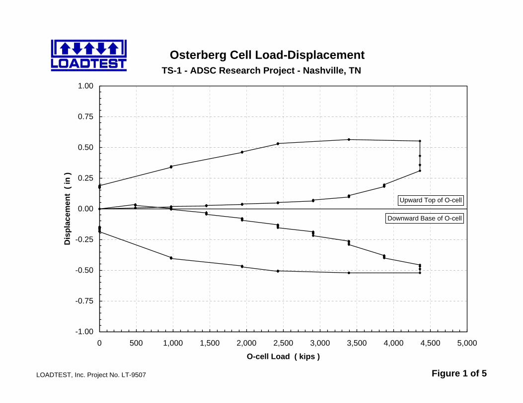
TS-1 - ADSC Research Project - Nashville, TN
LOADTEST, Inc. Project No. LT-9507 Figure 1 of 5
Osterberg Cell Load-Displacement
-1.00
-0.75
-0.50
-0.25
0.00
0.25
0.50
0.75
1.00
0 500 1,000 1,500 2,000 2,500 3,000 3,500 4,000 4,500 5,000
O-cell Load ( kips )
Dis
plac
emen
t ( i
n )
Upward Top of O-cell
Downward Base of O-cell
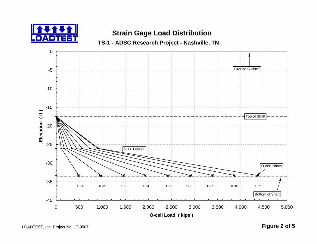
TS-1 - ADSC Research Project - Nashville, TN
LOADTEST, Inc. Project No. LT-9507 Figure 2 of 5
Strain Gage Load Distribution
-40
-35
-30
-25
-20
-15
-10
-5
0
0 500 1,000 1,500 2,000 2,500 3,000 3,500 4,000 4,500 5,000
O-cell Load ( kips )
Elev
atio
n (
ft )
Top of Shaft
Bottom of Shaft
1L-1 1L-2 1L-3 1L-4 1L-5 1L-6 1L-7 1L-8 1L-9
S. G. Level 1
O-cell Points
Ground Surface
TS-1 - ADSC Research Project - Nashville, TN
LOADTEST, Inc. Project No. LT-9507 Figure 3 of 5
Mobilized Net Unit Side Shear
0
5
10
15
20
25
30
35
40
0.00 0.25 0.50 0.75 1.00
Upward Average Shear Zone Displacement ( in )
Mob
ilize
d N
et U
nit S
ide
Shea
r ( k
sf )
S.G. Level 1 to Zero Shear
O-cell to S.G. Level 1
TS-1 - ADSC Research Project - Nashville, TN
LOADTEST, Inc. Project No. LT-9507 Figure 4 of 5
Mobilized Unit End Bearing
0
100
200
300
400
500
600
0.00 0.25 0.50 0.75 1.00
Downward O-cell Displacement ( in )
Mob
ilize
d U
nit E
nd B
earin
g (
ksf )
Note: This analysis assumes that the entire applied load is taken in end bearing over the 39-inch diameter loaded area at the base of the pile (36" bottom plate plus 2:1 load distribution over the 0.25 ft below the O-cell)
TS-1 - ADSC Research Project - Nashville, TN
LOADTEST, Inc. Project No. LT-9507 Figure 5 of 5
Equivalent Top Load-Displacement
-2.0
-1.8
-1.6
-1.4
-1.2
-1.0
-0.8
-0.6
-0.4
-0.2
0.00 1,000 2,000 3,000 4,000 5,000 6,000 7,000 8,000 9,000 10,000
Equivalent Top Load ( kips )
Dis
plac
emen
t ( i
n )
Thin Line - Rigid CurveThick Line - Rigid Curve Adjusted for Additional Elastic Compression
Minimum Creep Limit 8060 kips
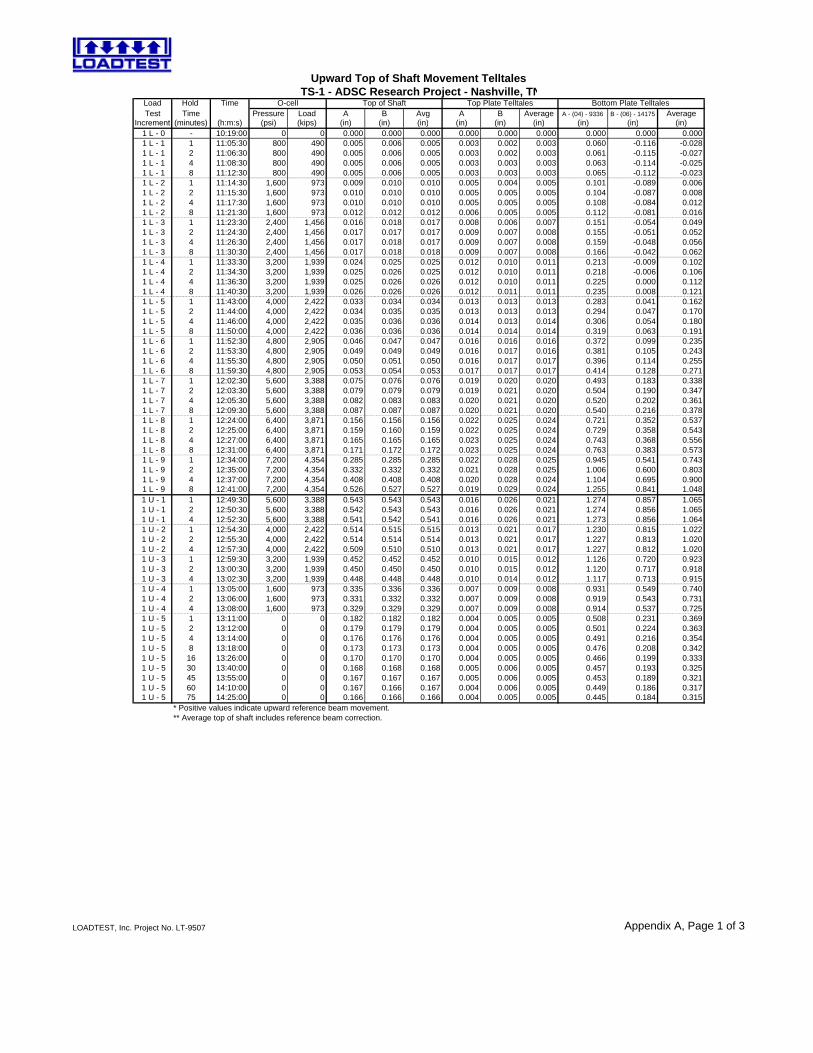
Load Hold Time O-cell Top of Shaft Top Plate TelltalesTest Time Pressure Load A B Avg A B Average A - (04) - 9336 B - (06) - 14175 Average
Increment (minutes) (h:m:s) (psi) (kips) (in) (in) (in) (in) (in) (in) (in) (in) (in) 1 L - 0 - 10:19:00 0 0 0.000 0.000 0.000 0.000 0.000 0.000 0.000 0.000 0.000 1 L - 1 1 11:05:30 800 490 0.005 0.006 0.005 0.003 0.002 0.003 0.060 -0.116 -0.028 1 L - 1 2 11:06:30 800 490 0.005 0.006 0.005 0.003 0.002 0.003 0.061 -0.115 -0.027 1 L - 1 4 11:08:30 800 490 0.005 0.006 0.005 0.003 0.003 0.003 0.063 -0.114 -0.025 1 L - 1 8 11:12:30 800 490 0.005 0.006 0.005 0.003 0.003 0.003 0.065 -0.112 -0.023 1 L - 2 1 11:14:30 1,600 973 0.009 0.010 0.010 0.005 0.004 0.005 0.101 -0.089 0.006 1 L - 2 2 11:15:30 1,600 973 0.010 0.010 0.010 0.005 0.005 0.005 0.104 -0.087 0.008 1 L - 2 4 11:17:30 1,600 973 0.010 0.010 0.010 0.005 0.005 0.005 0.108 -0.084 0.012 1 L - 2 8 11:21:30 1,600 973 0.012 0.012 0.012 0.006 0.005 0.005 0.112 -0.081 0.016 1 L - 3 1 11:23:30 2,400 1,456 0.016 0.018 0.017 0.008 0.006 0.007 0.151 -0.054 0.049 1 L - 3 2 11:24:30 2,400 1,456 0.017 0.017 0.017 0.009 0.007 0.008 0.155 -0.051 0.052 1 L - 3 4 11:26:30 2,400 1,456 0.017 0.018 0.017 0.009 0.007 0.008 0.159 -0.048 0.056 1 L - 3 8 11:30:30 2,400 1,456 0.017 0.018 0.018 0.009 0.007 0.008 0.166 -0.042 0.062 1 L - 4 1 11:33:30 3,200 1,939 0.024 0.025 0.025 0.012 0.010 0.011 0.213 -0.009 0.102 1 L - 4 2 11:34:30 3,200 1,939 0.025 0.026 0.025 0.012 0.010 0.011 0.218 -0.006 0.106 1 L - 4 4 11:36:30 3,200 1,939 0.025 0.026 0.026 0.012 0.010 0.011 0.225 0.000 0.112 1 L - 4 8 11:40:30 3,200 1,939 0.026 0.026 0.026 0.012 0.011 0.011 0.235 0.008 0.121 1 L - 5 1 11:43:00 4,000 2,422 0.033 0.034 0.034 0.013 0.013 0.013 0.283 0.041 0.162 1 L - 5 2 11:44:00 4,000 2,422 0.034 0.035 0.035 0.013 0.013 0.013 0.294 0.047 0.170 1 L - 5 4 11:46:00 4,000 2,422 0.035 0.036 0.036 0.014 0.013 0.014 0.306 0.054 0.180 1 L - 5 8 11:50:00 4,000 2,422 0.036 0.036 0.036 0.014 0.014 0.014 0.319 0.063 0.191 1 L - 6 1 11:52:30 4,800 2,905 0.046 0.047 0.047 0.016 0.016 0.016 0.372 0.099 0.235 1 L - 6 2 11:53:30 4,800 2,905 0.049 0.049 0.049 0.016 0.017 0.016 0.381 0.105 0.243 1 L - 6 4 11:55:30 4,800 2,905 0.050 0.051 0.050 0.016 0.017 0.017 0.396 0.114 0.255 1 L - 6 8 11:59:30 4,800 2,905 0.053 0.054 0.053 0.017 0.017 0.017 0.414 0.128 0.271 1 L - 7 1 12:02:30 5,600 3,388 0.075 0.076 0.076 0.019 0.020 0.020 0.493 0.183 0.338 1 L - 7 2 12:03:30 5,600 3,388 0.079 0.079 0.079 0.019 0.021 0.020 0.504 0.190 0.347 1 L - 7 4 12:05:30 5,600 3,388 0.082 0.083 0.083 0.020 0.021 0.020 0.520 0.202 0.361 1 L - 7 8 12:09:30 5,600 3,388 0.087 0.087 0.087 0.020 0.021 0.020 0.540 0.216 0.378 1 L - 8 1 12:24:00 6,400 3,871 0.156 0.156 0.156 0.022 0.025 0.024 0.721 0.352 0.537 1 L - 8 2 12:25:00 6,400 3,871 0.159 0.160 0.159 0.022 0.025 0.024 0.729 0.358 0.543 1 L - 8 4 12:27:00 6,400 3,871 0.165 0.165 0.165 0.023 0.025 0.024 0.743 0.368 0.556 1 L - 8 8 12:31:00 6,400 3,871 0.171 0.172 0.172 0.023 0.025 0.024 0.763 0.383 0.573 1 L - 9 1 12:34:00 7,200 4,354 0.285 0.285 0.285 0.022 0.028 0.025 0.945 0.541 0.743 1 L - 9 2 12:35:00 7,200 4,354 0.332 0.332 0.332 0.021 0.028 0.025 1.006 0.600 0.803 1 L - 9 4 12:37:00 7,200 4,354 0.408 0.408 0.408 0.020 0.028 0.024 1.104 0.695 0.900 1 L - 9 8 12:41:00 7,200 4,354 0.526 0.527 0.527 0.019 0.029 0.024 1.255 0.841 1.048 1 U - 1 1 12:49:30 5,600 3,388 0.543 0.543 0.543 0.016 0.026 0.021 1.274 0.857 1.065 1 U - 1 2 12:50:30 5,600 3,388 0.542 0.543 0.543 0.016 0.026 0.021 1.274 0.856 1.065 1 U - 1 4 12:52:30 5,600 3,388 0.541 0.542 0.541 0.016 0.026 0.021 1.273 0.856 1.064 1 U - 2 1 12:54:30 4,000 2,422 0.514 0.515 0.515 0.013 0.021 0.017 1.230 0.815 1.022 1 U - 2 2 12:55:30 4,000 2,422 0.514 0.514 0.514 0.013 0.021 0.017 1.227 0.813 1.020 1 U - 2 4 12:57:30 4,000 2,422 0.509 0.510 0.510 0.013 0.021 0.017 1.227 0.812 1.020 1 U - 3 1 12:59:30 3,200 1,939 0.452 0.452 0.452 0.010 0.015 0.012 1.126 0.720 0.923 1 U - 3 2 13:00:30 3,200 1,939 0.450 0.450 0.450 0.010 0.015 0.012 1.120 0.717 0.918 1 U - 3 4 13:02:30 3,200 1,939 0.448 0.448 0.448 0.010 0.014 0.012 1.117 0.713 0.915 1 U - 4 1 13:05:00 1,600 973 0.335 0.336 0.336 0.007 0.009 0.008 0.931 0.549 0.740 1 U - 4 2 13:06:00 1,600 973 0.331 0.332 0.332 0.007 0.009 0.008 0.919 0.543 0.731 1 U - 4 4 13:08:00 1,600 973 0.329 0.329 0.329 0.007 0.009 0.008 0.914 0.537 0.725 1 U - 5 1 13:11:00 0 0 0.182 0.182 0.182 0.004 0.005 0.005 0.508 0.231 0.369 1 U - 5 2 13:12:00 0 0 0.179 0.179 0.179 0.004 0.005 0.005 0.501 0.224 0.363 1 U - 5 4 13:14:00 0 0 0.176 0.176 0.176 0.004 0.005 0.005 0.491 0.216 0.354 1 U - 5 8 13:18:00 0 0 0.173 0.173 0.173 0.004 0.005 0.005 0.476 0.208 0.342 1 U - 5 16 13:26:00 0 0 0.170 0.170 0.170 0.004 0.005 0.005 0.466 0.199 0.333 1 U - 5 30 13:40:00 0 0 0.168 0.168 0.168 0.005 0.006 0.005 0.457 0.193 0.325 1 U - 5 45 13:55:00 0 0 0.167 0.167 0.167 0.005 0.006 0.005 0.453 0.189 0.321 1 U - 5 60 14:10:00 0 0 0.167 0.166 0.167 0.004 0.006 0.005 0.449 0.186 0.317 1 U - 5 75 14:25:00 0 0 0.166 0.166 0.166 0.004 0.005 0.005 0.445 0.184 0.315
* Positive values indicate upward reference beam movement.** Average top of shaft includes reference beam correction.
Upward Top of Shaft Movement Telltales TS-1 - ADSC Research Project - Nashville, TN
Bottom Plate Telltales
Appendix A, Page 1 of 3LOADTEST, Inc. Project No. LT-9507
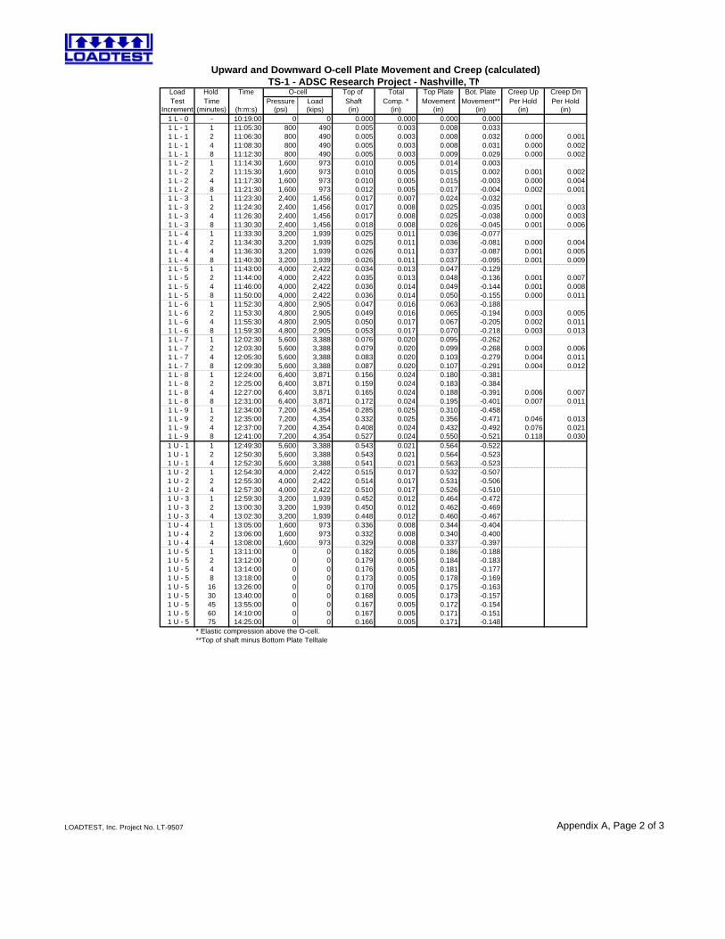
Load Hold Time O-cell Top of Total Top Plate Bot. Plate Creep Up Creep DnTest Time Pressure Load Shaft Comp. * Movement Movement** Per Hold Per Hold
Increment (minutes) (h:m:s) (psi) (kips) (in) (in) (in) (in) (in) (in) 1 L - 0 - 10:19:00 0 0 0.000 0.000 0.000 0.000 1 L - 1 1 11:05:30 800 490 0.005 0.003 0.008 0.033 1 L - 1 2 11:06:30 800 490 0.005 0.003 0.008 0.032 0.000 0.001 1 L - 1 4 11:08:30 800 490 0.005 0.003 0.008 0.031 0.000 0.002 1 L - 1 8 11:12:30 800 490 0.005 0.003 0.009 0.029 0.000 0.002 1 L - 2 1 11:14:30 1,600 973 0.010 0.005 0.014 0.003 0.006 0.025 1 L - 2 2 11:15:30 1,600 973 0.010 0.005 0.015 0.002 0.001 0.002 1 L - 2 4 11:17:30 1,600 973 0.010 0.005 0.015 -0.003 0.000 0.004 1 L - 2 8 11:21:30 1,600 973 0.012 0.005 0.017 -0.004 0.002 0.001 1 L - 3 1 11:23:30 2,400 1,456 0.017 0.007 0.024 -0.032 0.007 0.028 1 L - 3 2 11:24:30 2,400 1,456 0.017 0.008 0.025 -0.035 0.001 0.003 1 L - 3 4 11:26:30 2,400 1,456 0.017 0.008 0.025 -0.038 0.000 0.003 1 L - 3 8 11:30:30 2,400 1,456 0.018 0.008 0.026 -0.045 0.001 0.006 1 L - 4 1 11:33:30 3,200 1,939 0.025 0.011 0.036 -0.077 0.010 0.033 1 L - 4 2 11:34:30 3,200 1,939 0.025 0.011 0.036 -0.081 0.000 0.004 1 L - 4 4 11:36:30 3,200 1,939 0.026 0.011 0.037 -0.087 0.001 0.005 1 L - 4 8 11:40:30 3,200 1,939 0.026 0.011 0.037 -0.095 0.001 0.009 1 L - 5 1 11:43:00 4,000 2,422 0.034 0.013 0.047 -0.129 0.010 0.033 1 L - 5 2 11:44:00 4,000 2,422 0.035 0.013 0.048 -0.136 0.001 0.007 1 L - 5 4 11:46:00 4,000 2,422 0.036 0.014 0.049 -0.144 0.001 0.008 1 L - 5 8 11:50:00 4,000 2,422 0.036 0.014 0.050 -0.155 0.000 0.011 1 L - 6 1 11:52:30 4,800 2,905 0.047 0.016 0.063 -0.188 0.013 0.034 1 L - 6 2 11:53:30 4,800 2,905 0.049 0.016 0.065 -0.194 0.003 0.005 1 L - 6 4 11:55:30 4,800 2,905 0.050 0.017 0.067 -0.205 0.002 0.011 1 L - 6 8 11:59:30 4,800 2,905 0.053 0.017 0.070 -0.218 0.003 0.013 1 L - 7 1 12:02:30 5,600 3,388 0.076 0.020 0.095 -0.262 0.025 0.044 1 L - 7 2 12:03:30 5,600 3,388 0.079 0.020 0.099 -0.268 0.003 0.006 1 L - 7 4 12:05:30 5,600 3,388 0.083 0.020 0.103 -0.279 0.004 0.011 1 L - 7 8 12:09:30 5,600 3,388 0.087 0.020 0.107 -0.291 0.004 0.012 1 L - 8 1 12:24:00 6,400 3,871 0.156 0.024 0.180 -0.381 0.072 0.090 1 L - 8 2 12:25:00 6,400 3,871 0.159 0.024 0.183 -0.384 0.003 0.004 1 L - 8 4 12:27:00 6,400 3,871 0.165 0.024 0.188 -0.391 0.006 0.007 1 L - 8 8 12:31:00 6,400 3,871 0.172 0.024 0.195 -0.401 0.007 0.011 1 L - 9 1 12:34:00 7,200 4,354 0.285 0.025 0.310 -0.458 0.115 0.056 1 L - 9 2 12:35:00 7,200 4,354 0.332 0.025 0.356 -0.471 0.046 0.013 1 L - 9 4 12:37:00 7,200 4,354 0.408 0.024 0.432 -0.492 0.076 0.021 1 L - 9 8 12:41:00 7,200 4,354 0.527 0.024 0.550 -0.521 0.118 0.030 1 U - 1 1 12:49:30 5,600 3,388 0.543 0.021 0.564 -0.522 1 U - 1 2 12:50:30 5,600 3,388 0.543 0.021 0.564 -0.523 1 U - 1 4 12:52:30 5,600 3,388 0.541 0.021 0.563 -0.523 1 U - 2 1 12:54:30 4,000 2,422 0.515 0.017 0.532 -0.507 1 U - 2 2 12:55:30 4,000 2,422 0.514 0.017 0.531 -0.506 1 U - 2 4 12:57:30 4,000 2,422 0.510 0.017 0.526 -0.510 1 U - 3 1 12:59:30 3,200 1,939 0.452 0.012 0.464 -0.472 1 U - 3 2 13:00:30 3,200 1,939 0.450 0.012 0.462 -0.469 1 U - 3 4 13:02:30 3,200 1,939 0.448 0.012 0.460 -0.467 1 U - 4 1 13:05:00 1,600 973 0.336 0.008 0.344 -0.404 1 U - 4 2 13:06:00 1,600 973 0.332 0.008 0.340 -0.400 1 U - 4 4 13:08:00 1,600 973 0.329 0.008 0.337 -0.397 1 U - 5 1 13:11:00 0 0 0.182 0.005 0.186 -0.188 1 U - 5 2 13:12:00 0 0 0.179 0.005 0.184 -0.183 1 U - 5 4 13:14:00 0 0 0.176 0.005 0.181 -0.177 1 U - 5 8 13:18:00 0 0 0.173 0.005 0.178 -0.169 1 U - 5 16 13:26:00 0 0 0.170 0.005 0.175 -0.163 1 U - 5 30 13:40:00 0 0 0.168 0.005 0.173 -0.157 1 U - 5 45 13:55:00 0 0 0.167 0.005 0.172 -0.154 1 U - 5 60 14:10:00 0 0 0.167 0.005 0.171 -0.151 1 U - 5 75 14:25:00 0 0 0.166 0.005 0.171 -0.148
* Elastic compression above the O-cell.**Top of shaft minus Bottom Plate Telltale
TS-1 - ADSC Research Project - Nashville, TNUpward and Downward O-cell Plate Movement and Creep (calculated)
Appendix A, Page 2 of 3LOADTEST, Inc. Project No. LT-9507
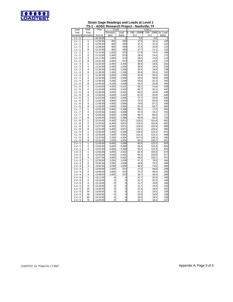
Load Hold Time O-cellTest Time Pressure Load A - (08) - 19984B - (08) - 19985 Av. Load
Increment (minutes) (h:m:s) (psi) (kips) (µε) (µε) (kips) 1 L - 0 - 10:19:00 0 0 0.0 0.0 0 1 L - 1 1 11:05:30 800 490 17.0 10.1 108 1 L - 1 2 11:06:30 800 490 17.1 10.3 110 1 L - 1 4 11:08:30 800 490 17.4 10.9 114 1 L - 1 8 11:12:30 800 490 17.7 11.1 115 1 L - 2 1 11:14:30 1,600 973 27.9 14.2 169 1 L - 2 2 11:15:30 1,600 973 28.4 14.5 172 1 L - 2 4 11:17:30 1,600 973 28.5 14.6 173 1 L - 2 8 11:21:30 1,600 973 28.8 14.8 175 1 L - 3 1 11:23:30 2,400 1,456 38.6 19.3 232 1 L - 3 2 11:24:30 2,400 1,456 38.9 19.5 234 1 L - 3 4 11:26:30 2,400 1,456 39.4 19.9 238 1 L - 3 8 11:30:30 2,400 1,456 39.9 20.4 242 1 L - 4 1 11:33:30 3,200 1,939 52.6 30.2 332 1 L - 4 2 11:34:30 3,200 1,939 53.0 30.8 336 1 L - 4 4 11:36:30 3,200 1,939 53.6 31.2 340 1 L - 4 8 11:40:30 3,200 1,939 54.2 31.8 345 1 L - 5 1 11:43:00 4,000 2,422 65.1 41.6 428 1 L - 5 2 11:44:00 4,000 2,422 65.7 42.1 432 1 L - 5 4 11:46:00 4,000 2,422 66.3 42.8 438 1 L - 5 8 11:50:00 4,000 2,422 67.0 43.9 445 1 L - 6 1 11:52:30 4,800 2,905 77.7 54.5 530 1 L - 6 2 11:53:30 4,800 2,905 78.3 55.8 538 1 L - 6 4 11:55:30 4,800 2,905 79.6 57.2 549 1 L - 6 8 11:59:30 4,800 2,905 81.0 59.7 564 1 L - 7 1 12:02:30 5,600 3,388 96.1 77.0 694 1 L - 7 2 12:03:30 5,600 3,388 97.0 78.1 702 1 L - 7 4 12:05:30 5,600 3,388 98.7 80.0 717 1 L - 7 8 12:09:30 5,600 3,388 99.9 82.0 729 1 L - 8 1 12:24:00 6,400 3,871 118.1 101.6 881 1 L - 8 2 12:25:00 6,400 3,871 118.2 101.8 882 1 L - 8 4 12:27:00 6,400 3,871 118.5 102.9 888 1 L - 8 8 12:31:00 6,400 3,871 119.1 104.4 896 1 L - 9 1 12:34:00 7,200 4,354 119.3 123.2 972 1 L - 9 2 12:35:00 7,200 4,354 112.4 124.1 948 1 L - 9 4 12:37:00 7,200 4,354 107.0 126.1 935 1 L - 9 8 12:41:00 7,200 4,354 99.1 130.7 921 1 U - 1 1 12:49:30 5,600 3,388 83.4 122.2 824 1 U - 1 2 12:50:30 5,600 3,388 83.3 122.3 825 1 U - 1 4 12:52:30 5,600 3,388 83.2 122.3 824 1 U - 2 1 12:54:30 4,000 2,422 64.9 103.3 674 1 U - 2 2 12:55:30 4,000 2,422 65.2 103.6 677 1 U - 2 4 12:57:30 4,000 2,422 64.6 103.1 672 1 U - 3 1 12:59:30 3,200 1,939 47.3 76.0 494 1 U - 3 2 13:00:30 3,200 1,939 46.8 75.2 489 1 U - 3 4 13:02:30 3,200 1,939 46.3 74.6 485 1 U - 4 1 13:05:00 1,600 973 27.5 46.8 298 1 U - 4 2 13:06:00 1,600 973 27.2 46.0 293 1 U - 4 4 13:08:00 1,600 973 26.7 45.4 289 1 U - 5 1 13:11:00 0 0 21.7 20.3 168 1 U - 5 2 13:12:00 0 0 21.7 20.1 168 1 U - 5 4 13:14:00 0 0 21.7 19.6 166 1 U - 5 8 13:18:00 0 0 21.7 19.0 163 1 U - 5 16 13:26:00 0 0 21.5 18.9 162 1 U - 5 30 13:40:00 0 0 21.1 18.5 159 1 U - 5 45 13:55:00 0 0 20.9 18.5 158 1 U - 5 60 14:10:00 0 0 20.9 18.5 158 1 U - 5 75 14:25:00 0 0 20.7 18.4 157
Level 1
Strain Gage Readings and Loads at Level 1TS-1 - ADSC Research Project - Nashville, TN
Appendix A, Page 3 of 3LOADTEST, Inc. Project No. LT-9507
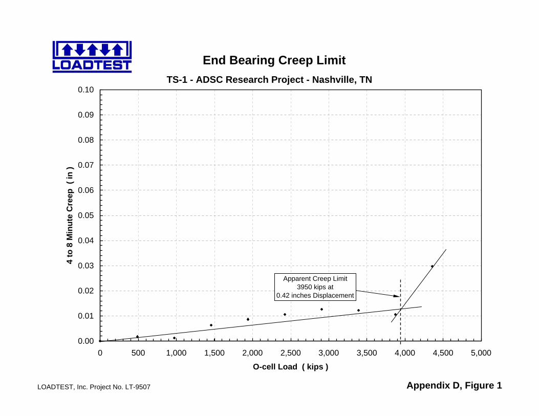
TS-1 - ADSC Research Project - Nashville, TN
LOADTEST, Inc. Project No. LT-9507 Appendix D, Figure 1
End Bearing Creep Limit
0.00
0.01
0.02
0.03
0.04
0.05
0.06
0.07
0.08
0.09
0.10
0 500 1,000 1,500 2,000 2,500 3,000 3,500 4,000 4,500 5,000
O-cell Load ( kips )
4 to
8 M
inut
e C
reep
( in
)
Apparent Creep Limit3950 kips at
0.42 inches Displacement
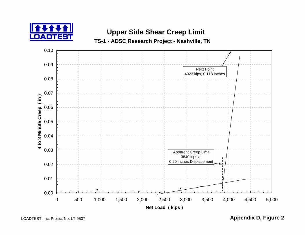
TS-1 - ADSC Research Project - Nashville, TN
LOADTEST, Inc. Project No. LT-9507 Appendix D, Figure 2
Upper Side Shear Creep Limit
0.00
0.01
0.02
0.03
0.04
0.05
0.06
0.07
0.08
0.09
0.10
0 500 1,000 1,500 2,000 2,500 3,000 3,500 4,000 4,500 5,000
Net Load ( kips )
4 to
8 M
inut
e C
reep
( in
)
Next Point4323 kips, 0.118 inches
Apparent Creep Limit3840 kips at
0.20 inches Displacement
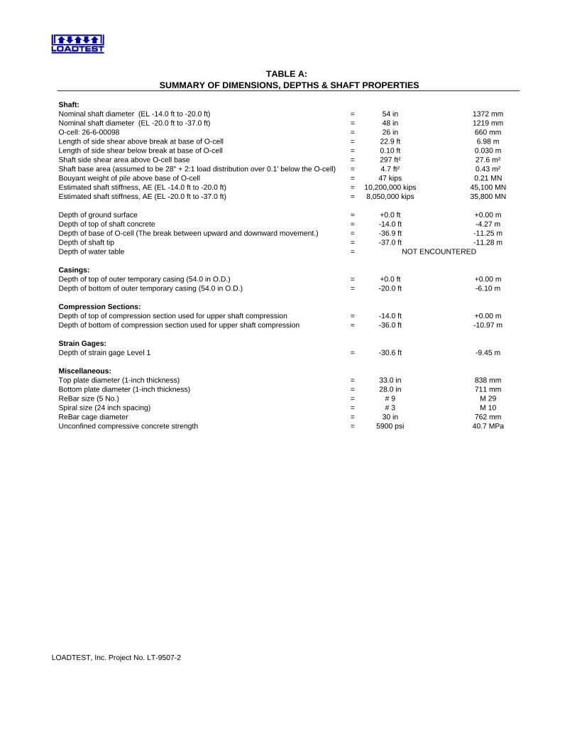
TABLE A: SUMMARY OF DIMENSIONS, DEPTHS & SHAFT PROPERTIES
Shaft:Nominal shaft diameter (EL -14.0 ft to -20.0 ft) = 54 in 1372 mmNominal shaft diameter (EL -20.0 ft to -37.0 ft) = 48 in 1219 mmO-cell: 26-6-00098 = 26 in 660 mmLength of side shear above break at base of O-cell = 22.9 ft 6.98 mLength of side shear below break at base of O-cell = 0.10 ft 0.030 mShaft side shear area above O-cell base = 297 ft² 27.6 m²Shaft base area (assumed to be 28" + 2:1 load distribution over 0.1' below the O-cell) = 4.7 ft² 0.43 m²Bouyant weight of pile above base of O-cell = 47 kips 0.21 MNEstimated shaft stiffness, AE (EL -14.0 ft to -20.0 ft) = 10,200,000 kips 45,100 MNEstimated shaft stiffness, AE (EL -20.0 ft to -37.0 ft) = 8,050,000 kips 35,800 MN
Depth of ground surface = +0.0 ft +0.00 mDepth of top of shaft concrete = -14.0 ft -4.27 mDepth of base of O-cell (The break between upward and downward movement.) = -36.9 ft -11.25 mDepth of shaft tip = -37.0 ft -11.28 mDepth of water table = NOT ENCOUNTERED
Casings:Depth of top of outer temporary casing (54.0 in O.D.) = +0.0 ft +0.00 mDepth of bottom of outer temporary casing (54.0 in O.D.) = -20.0 ft -6.10 m
Compression Sections:Depth of top of compression section used for upper shaft compression = -14.0 ft +0.00 mDepth of bottom of compression section used for upper shaft compression = -36.0 ft -10.97 m
Strain Gages:Depth of strain gage Level 1 = -30.6 ft -9.45 m
Miscellaneous:Top plate diameter (1-inch thickness) = 33.0 in 838 mmBottom plate diameter (1-inch thickness) = 28.0 in 711 mmReBar size (5 No.) = # 9 M 29Spiral size (24 inch spacing) = # 3 M 10ReBar cage diameter = 30 in 762 mmUnconfined compressive concrete strength = 5900 psi 40.7 MPa
LOADTEST, Inc. Project No. LT-9507-2
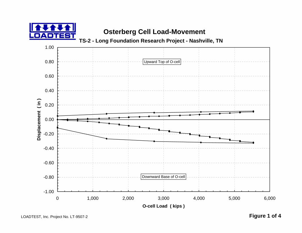
TS-2 - Long Foundation Research Project - Nashville, TN
LOADTEST, Inc. Project No. LT-9507-2 Figure 1 of 4
Osterberg Cell Load-Movement
-1.00
-0.80
-0.60
-0.40
-0.20
0.00
0.20
0.40
0.60
0.80
1.00
0 1,000 2,000 3,000 4,000 5,000 6,000
O-cell Load ( kips )
Dis
plac
emen
t ( i
n )
Upward Top of O-cell
Downward Base of O-cell
TS-2 - Long Foundation Research Project - Nashville, TN
LOADTEST, Inc. Project No. LT-9507-2 Figure 2 of 4
Strain Gage Load Distribution
-40
-35
-30
-25
-20
-15
-10
-5
0
0 1,000 2,000 3,000 4,000 5,000 6,000
O-cell Load ( kips )
Dep
th (
ft )
Top of Shaft
Bottom of Shaft
1L-1 1L-3 1L-5 1L-7 1L-9
S. G. Level 1
O-cell
1L-11 1L-13 1L-191L-171L-15
Ground Surface
TS-2 - Long Foundation Research Project - Nashville, TN
LOADTEST, Inc. Project No. LT-9507-2 Figure 3 of 4
Mobilized Net Unit Side Shear
0
10
20
30
40
50
60
0.00 0.25 0.50 0.75 1.00
Upward Average Shear Zone Displacement ( in )
Mob
ilize
d N
et U
nit S
ide
Shea
r ( k
sf )
S.G. Level 1 to Top of Shaft
O-cell to S.G. Level 1

TS-2 - Long Foundation Research Project - Nashville, TN
LOADTEST, Inc. Project No. LT-9507-2 Figure 4 of 4
Mobilized Unit End Bearing
0
200
400
600
800
1000
1200
1400
0.00 0.25 0.50 0.75 1.00
Downward O-cell Displacement ( in )
Mob
ilize
d U
nit E
nd B
earin
g (
ksf )
Note: This analysis assumes that the entire applied load is taken in end bearing over the 29.2-inch diameter loaded area at the base of the pile (28" bottom plate plus 2:1 load distribution over the 0.1 ft below the O-cell)
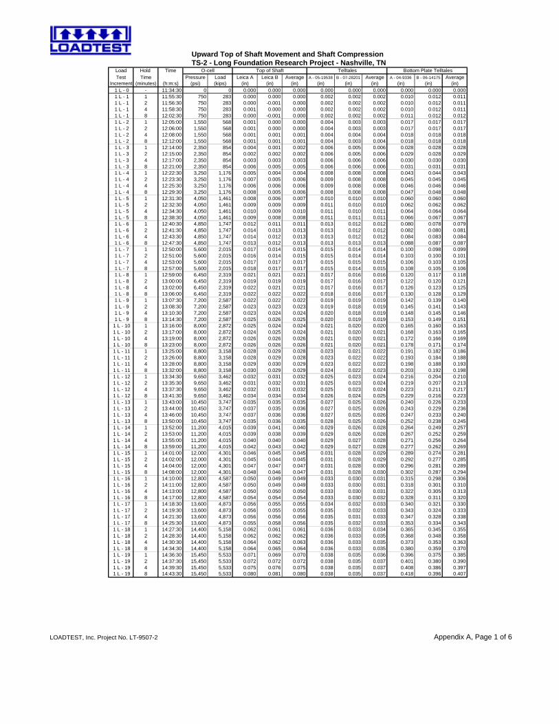
Load Hold Time O-cell Top of Shaft TelltalesTest Time Pressure Load Leica A Leica B Average A - 05-19538 B - 07-28201 Average A - 04-9336 B - 06-14175 Average
Increment (minutes) (h:m:s) (psi) (kips) (in) (in) (in) (in) (in) (in) (in) (in) (in) 1 L - 0 - 11:34:30 0 0 0.000 0.000 0.000 0.000 0.000 0.000 0.000 0.000 0.000 1 L - 1 1 11:55:30 750 283 0.000 0.000 0.000 0.002 0.002 0.002 0.010 0.012 0.011 1 L - 1 2 11:56:30 750 283 0.000 -0.001 0.000 0.002 0.002 0.002 0.010 0.012 0.011 1 L - 1 4 11:58:30 750 283 0.001 0.000 0.000 0.002 0.002 0.002 0.010 0.012 0.011 1 L - 1 8 12:02:30 750 283 0.000 -0.001 0.000 0.002 0.002 0.002 0.011 0.012 0.012 1 L - 2 1 12:05:00 1,550 568 0.001 0.000 0.000 0.004 0.003 0.003 0.017 0.017 0.017 1 L - 2 2 12:06:00 1,550 568 0.001 0.000 0.000 0.004 0.003 0.003 0.017 0.017 0.017 1 L - 2 4 12:08:00 1,550 568 0.001 0.001 0.001 0.004 0.004 0.004 0.018 0.018 0.018 1 L - 2 8 12:12:00 1,550 568 0.001 0.001 0.001 0.004 0.003 0.004 0.018 0.018 0.018 1 L - 3 1 12:14:00 2,350 854 0.004 0.001 0.002 0.006 0.005 0.006 0.028 0.028 0.028 1 L - 3 2 12:15:00 2,350 854 0.002 0.002 0.002 0.006 0.005 0.006 0.029 0.028 0.029 1 L - 3 4 12:17:00 2,350 854 0.003 0.003 0.003 0.006 0.006 0.006 0.030 0.030 0.030 1 L - 3 8 12:21:00 2,350 854 0.006 0.005 0.005 0.006 0.006 0.006 0.031 0.031 0.031 1 L - 4 1 12:22:30 3,250 1,176 0.005 0.004 0.004 0.008 0.008 0.008 0.043 0.044 0.043 1 L - 4 2 12:23:30 3,250 1,176 0.007 0.005 0.006 0.009 0.008 0.008 0.045 0.045 0.045 1 L - 4 4 12:25:30 3,250 1,176 0.006 0.006 0.006 0.009 0.008 0.008 0.046 0.046 0.046 1 L - 4 8 12:29:30 3,250 1,176 0.008 0.005 0.006 0.008 0.008 0.008 0.047 0.048 0.048 1 L - 5 1 12:31:30 4,050 1,461 0.008 0.006 0.007 0.010 0.010 0.010 0.060 0.060 0.060 1 L - 5 2 12:32:30 4,050 1,461 0.009 0.009 0.009 0.011 0.010 0.010 0.062 0.062 0.062 1 L - 5 4 12:34:30 4,050 1,461 0.010 0.009 0.010 0.011 0.010 0.011 0.064 0.064 0.064 1 L - 5 8 12:38:30 4,050 1,461 0.009 0.008 0.008 0.011 0.011 0.011 0.066 0.067 0.067 1 L - 6 1 12:40:30 4,850 1,747 0.012 0.011 0.011 0.013 0.012 0.012 0.080 0.078 0.079 1 L - 6 2 12:41:30 4,850 1,747 0.014 0.013 0.013 0.013 0.012 0.012 0.082 0.080 0.081 1 L - 6 4 12:43:30 4,850 1,747 0.014 0.012 0.013 0.013 0.012 0.012 0.084 0.083 0.084 1 L - 6 8 12:47:30 4,850 1,747 0.013 0.012 0.013 0.013 0.013 0.013 0.088 0.087 0.087 1 L - 7 1 12:50:00 5,600 2,015 0.017 0.014 0.015 0.015 0.014 0.014 0.100 0.098 0.099 1 L - 7 2 12:51:00 5,600 2,015 0.016 0.014 0.015 0.015 0.014 0.014 0.103 0.100 0.101 1 L - 7 4 12:53:00 5,600 2,015 0.017 0.017 0.017 0.015 0.015 0.015 0.106 0.103 0.105 1 L - 7 8 12:57:00 5,600 2,015 0.018 0.017 0.017 0.015 0.014 0.015 0.108 0.105 0.106 1 L - 8 1 12:59:00 6,450 2,319 0.021 0.021 0.021 0.017 0.016 0.016 0.120 0.117 0.118 1 L - 8 2 13:00:00 6,450 2,319 0.019 0.019 0.019 0.017 0.016 0.017 0.122 0.120 0.121 1 L - 8 4 13:02:00 6,450 2,319 0.022 0.021 0.021 0.017 0.016 0.017 0.126 0.123 0.125 1 L - 8 8 13:06:00 6,450 2,319 0.022 0.022 0.022 0.018 0.016 0.017 0.130 0.128 0.129 1 L - 9 1 13:07:30 7,200 2,587 0.022 0.022 0.022 0.019 0.019 0.019 0.142 0.139 0.140 1 L - 9 2 13:08:30 7,200 2,587 0.023 0.023 0.023 0.019 0.018 0.019 0.145 0.141 0.143 1 L - 9 4 13:10:30 7,200 2,587 0.023 0.024 0.024 0.020 0.018 0.019 0.148 0.145 0.146 1 L - 9 8 13:14:30 7,200 2,587 0.025 0.026 0.025 0.020 0.019 0.019 0.153 0.149 0.151
1 L - 10 1 13:16:00 8,000 2,872 0.025 0.024 0.024 0.021 0.020 0.020 0.165 0.160 0.163 1 L - 10 2 13:17:00 8,000 2,872 0.024 0.025 0.024 0.021 0.020 0.021 0.168 0.163 0.165 1 L - 10 4 13:19:00 8,000 2,872 0.026 0.026 0.026 0.021 0.020 0.021 0.172 0.166 0.169 1 L - 10 8 13:23:00 8,000 2,872 0.026 0.026 0.026 0.021 0.020 0.021 0.178 0.171 0.174 1 L - 11 1 13:25:00 8,800 3,158 0.028 0.029 0.028 0.023 0.021 0.022 0.191 0.182 0.186 1 L - 11 2 13:26:00 8,800 3,158 0.028 0.029 0.028 0.023 0.022 0.022 0.193 0.184 0.188 1 L - 11 4 13:28:00 8,800 3,158 0.029 0.030 0.029 0.023 0.022 0.022 0.198 0.188 0.193 1 L - 11 8 13:32:00 8,800 3,158 0.030 0.029 0.029 0.024 0.022 0.023 0.203 0.192 0.198 1 L - 12 1 13:34:30 9,650 3,462 0.032 0.031 0.032 0.025 0.023 0.024 0.216 0.204 0.210 1 L - 12 2 13:35:30 9,650 3,462 0.031 0.032 0.031 0.025 0.023 0.024 0.219 0.207 0.213 1 L - 12 4 13:37:30 9,650 3,462 0.032 0.031 0.032 0.025 0.023 0.024 0.223 0.211 0.217 1 L - 12 8 13:41:30 9,650 3,462 0.034 0.034 0.034 0.026 0.024 0.025 0.229 0.216 0.223 1 L - 13 1 13:43:00 10,450 3,747 0.035 0.035 0.035 0.027 0.025 0.026 0.240 0.226 0.233 1 L - 13 2 13:44:00 10,450 3,747 0.037 0.035 0.036 0.027 0.025 0.026 0.243 0.229 0.236 1 L - 13 4 13:46:00 10,450 3,747 0.037 0.036 0.036 0.027 0.025 0.026 0.247 0.233 0.240 1 L - 13 8 13:50:00 10,450 3,747 0.035 0.036 0.035 0.028 0.025 0.026 0.252 0.238 0.245 1 L - 14 1 13:52:00 11,200 4,015 0.039 0.041 0.040 0.029 0.026 0.028 0.264 0.249 0.257 1 L - 14 2 13:53:00 11,200 4,015 0.039 0.038 0.039 0.029 0.026 0.028 0.267 0.252 0.259 1 L - 14 4 13:55:00 11,200 4,015 0.040 0.040 0.040 0.029 0.027 0.028 0.271 0.256 0.264 1 L - 14 8 13:59:00 11,200 4,015 0.042 0.043 0.042 0.029 0.027 0.028 0.277 0.262 0.269 1 L - 15 1 14:01:00 12,000 4,301 0.046 0.045 0.045 0.031 0.028 0.029 0.289 0.274 0.281 1 L - 15 2 14:02:00 12,000 4,301 0.045 0.044 0.045 0.031 0.028 0.029 0.292 0.277 0.285 1 L - 15 4 14:04:00 12,000 4,301 0.047 0.047 0.047 0.031 0.028 0.030 0.296 0.281 0.289 1 L - 15 8 14:08:00 12,000 4,301 0.048 0.046 0.047 0.031 0.028 0.030 0.302 0.287 0.294 1 L - 16 1 14:10:00 12,800 4,587 0.050 0.049 0.049 0.033 0.030 0.031 0.315 0.298 0.306 1 L - 16 2 14:11:00 12,800 4,587 0.050 0.049 0.049 0.033 0.030 0.031 0.318 0.301 0.310 1 L - 16 4 14:13:00 12,800 4,587 0.050 0.050 0.050 0.033 0.030 0.031 0.322 0.305 0.313 1 L - 16 8 14:17:00 12,800 4,587 0.054 0.054 0.054 0.033 0.030 0.032 0.328 0.311 0.320 1 L - 17 1 14:18:30 13,600 4,873 0.056 0.055 0.055 0.034 0.032 0.033 0.340 0.321 0.330 1 L - 17 2 14:19:30 13,600 4,873 0.056 0.055 0.055 0.035 0.032 0.033 0.343 0.324 0.333 1 L - 17 4 14:21:30 13,600 4,873 0.056 0.056 0.056 0.035 0.031 0.033 0.347 0.328 0.338 1 L - 17 8 14:25:30 13,600 4,873 0.055 0.058 0.056 0.035 0.032 0.033 0.353 0.334 0.343 1 L - 18 1 14:27:30 14,400 5,158 0.062 0.061 0.061 0.036 0.033 0.034 0.365 0.345 0.355 1 L - 18 2 14:28:30 14,400 5,158 0.062 0.062 0.062 0.036 0.033 0.035 0.368 0.348 0.358 1 L - 18 4 14:30:30 14,400 5,158 0.064 0.062 0.063 0.036 0.033 0.035 0.373 0.353 0.363 1 L - 18 8 14:34:30 14,400 5,158 0.064 0.065 0.064 0.036 0.033 0.035 0.380 0.359 0.370 1 L - 19 1 14:36:30 15,450 5,533 0.071 0.069 0.070 0.038 0.035 0.036 0.396 0.375 0.385 1 L - 19 2 14:37:30 15,450 5,533 0.072 0.072 0.072 0.038 0.035 0.037 0.401 0.380 0.390 1 L - 19 4 14:39:30 15,450 5,533 0.075 0.076 0.075 0.038 0.035 0.037 0.408 0.386 0.397 1 L - 19 8 14:43:30 15,450 5,533 0.080 0.081 0.080 0.038 0.035 0.037 0.418 0.396 0.407
Upward Top of Shaft Movement and Shaft Compression TS-2 - Long Foundation Research Project - Nashville, TN
Bottom Plate Telltales
LOADTEST, Inc. Project No. LT-9507-2 Appendix A, Page 1 of 6
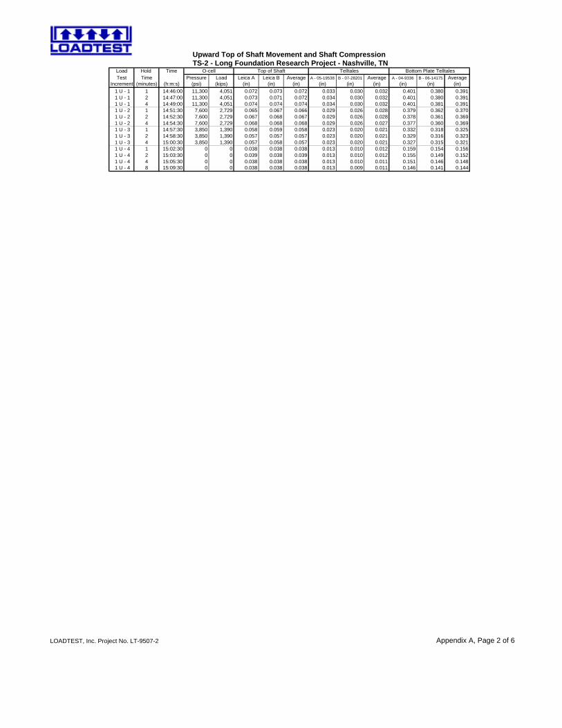
Load Hold Time O-cell Top of Shaft TelltalesTest Time Pressure Load Leica A Leica B Average A - 05-19538 B - 07-28201 Average A - 04-9336 B - 06-14175 Average
Increment (minutes) (h:m:s) (psi) (kips) (in) (in) (in) (in) (in) (in) (in) (in) (in)
Upward Top of Shaft Movement and Shaft Compression TS-2 - Long Foundation Research Project - Nashville, TN
Bottom Plate Telltales
1 U - 1 1 14:46:00 11,300 4,051 0.072 0.073 0.072 0.033 0.030 0.032 0.401 0.380 0.391 1 U - 1 2 14:47:00 11,300 4,051 0.073 0.071 0.072 0.034 0.030 0.032 0.401 0.380 0.391 1 U - 1 4 14:49:00 11,300 4,051 0.074 0.074 0.074 0.034 0.030 0.032 0.401 0.381 0.391 1 U - 2 1 14:51:30 7,600 2,729 0.065 0.067 0.066 0.029 0.026 0.028 0.379 0.362 0.370 1 U - 2 2 14:52:30 7,600 2,729 0.067 0.068 0.067 0.029 0.026 0.028 0.378 0.361 0.369 1 U - 2 4 14:54:30 7,600 2,729 0.068 0.068 0.068 0.029 0.026 0.027 0.377 0.360 0.369 1 U - 3 1 14:57:30 3,850 1,390 0.058 0.059 0.058 0.023 0.020 0.021 0.332 0.318 0.325 1 U - 3 2 14:58:30 3,850 1,390 0.057 0.057 0.057 0.023 0.020 0.021 0.329 0.316 0.323 1 U - 3 4 15:00:30 3,850 1,390 0.057 0.058 0.057 0.023 0.020 0.021 0.327 0.315 0.321 1 U - 4 1 15:02:30 0 0 0.038 0.038 0.038 0.013 0.010 0.012 0.159 0.154 0.156 1 U - 4 2 15:03:30 0 0 0.039 0.038 0.039 0.013 0.010 0.012 0.155 0.149 0.152 1 U - 4 4 15:05:30 0 0 0.038 0.038 0.038 0.013 0.010 0.011 0.151 0.146 0.148 1 U - 4 8 15:09:30 0 0 0.038 0.038 0.038 0.013 0.009 0.011 0.146 0.141 0.144
LOADTEST, Inc. Project No. LT-9507-2 Appendix A, Page 2 of 6
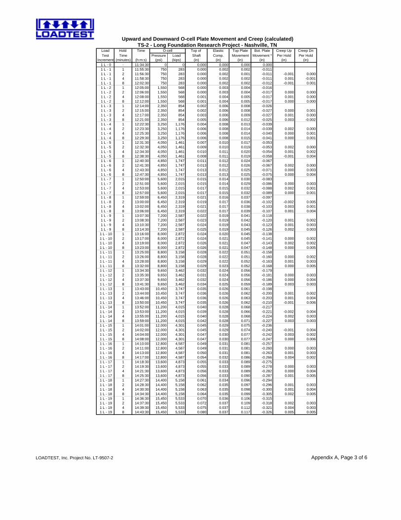
Load Hold Time O-cell Top of Elastic Top Plate Bot. Plate Creep Up Creep DnTest Time Pressure Load Shaft Comp. Movement Movement * Per Hold Per Hold
Increment (minutes) (h:m:s) (psi) (kips) (in) (in) (in) (in) (in) (in) 1 L - 0 - 11:34:30 0 0 0.000 0.000 0.000 0.000 1 L - 1 1 11:55:30 750 283 0.000 0.002 0.002 -0.011 1 L - 1 2 11:56:30 750 283 0.000 0.002 0.001 -0.011 -0.001 0.000 1 L - 1 4 11:58:30 750 283 0.000 0.002 0.002 -0.011 0.001 -0.001 1 L - 1 8 12:02:30 750 283 0.000 0.002 0.002 -0.012 -0.001 0.001 1 L - 2 1 12:05:00 1,550 568 0.000 0.003 0.004 -0.016 1 L - 2 2 12:06:00 1,550 568 0.000 0.003 0.004 -0.017 0.000 0.000 1 L - 2 4 12:08:00 1,550 568 0.001 0.004 0.005 -0.017 0.001 0.000 1 L - 2 8 12:12:00 1,550 568 0.001 0.004 0.005 -0.017 0.000 0.000 1 L - 3 1 12:14:00 2,350 854 0.002 0.006 0.008 -0.026 1 L - 3 2 12:15:00 2,350 854 0.002 0.006 0.008 -0.027 0.000 0.001 1 L - 3 4 12:17:00 2,350 854 0.003 0.006 0.009 -0.027 0.001 0.000 1 L - 3 8 12:21:00 2,350 854 0.005 0.006 0.012 -0.025 0.003 -0.002 1 L - 4 1 12:22:30 3,250 1,176 0.004 0.008 0.013 -0.039 1 L - 4 2 12:23:30 3,250 1,176 0.006 0.008 0.014 -0.039 0.002 0.000 1 L - 4 4 12:25:30 3,250 1,176 0.006 0.008 0.014 -0.040 0.000 0.001 1 L - 4 8 12:29:30 3,250 1,176 0.006 0.008 0.015 -0.041 0.000 0.001 1 L - 5 1 12:31:30 4,050 1,461 0.007 0.010 0.017 -0.053 1 L - 5 2 12:32:30 4,050 1,461 0.009 0.010 0.019 -0.053 0.002 0.000 1 L - 5 4 12:34:30 4,050 1,461 0.010 0.011 0.020 -0.054 0.001 0.002 1 L - 5 8 12:38:30 4,050 1,461 0.008 0.011 0.019 -0.058 -0.001 0.004 1 L - 6 1 12:40:30 4,850 1,747 0.011 0.012 0.024 -0.067 1 L - 6 2 12:41:30 4,850 1,747 0.013 0.012 0.026 -0.067 0.002 0.000 1 L - 6 4 12:43:30 4,850 1,747 0.013 0.012 0.025 -0.071 0.000 0.003 1 L - 6 8 12:47:30 4,850 1,747 0.013 0.013 0.025 -0.075 0.000 0.004 1 L - 7 1 12:50:00 5,600 2,015 0.015 0.014 0.030 -0.083 1 L - 7 2 12:51:00 5,600 2,015 0.015 0.014 0.029 -0.086 0.000 0.003 1 L - 7 4 12:53:00 5,600 2,015 0.017 0.015 0.032 -0.088 0.002 0.001 1 L - 7 8 12:57:00 5,600 2,015 0.017 0.015 0.032 -0.089 0.000 0.001 1 L - 8 1 12:59:00 6,450 2,319 0.021 0.016 0.037 -0.097 1 L - 8 2 13:00:00 6,450 2,319 0.019 0.017 0.036 -0.102 -0.002 0.005 1 L - 8 4 13:02:00 6,450 2,319 0.021 0.017 0.038 -0.103 0.003 0.001 1 L - 8 8 13:06:00 6,450 2,319 0.022 0.017 0.039 -0.107 0.001 0.004 1 L - 9 1 13:07:30 7,200 2,587 0.022 0.019 0.041 -0.118 1 L - 9 2 13:08:30 7,200 2,587 0.023 0.019 0.042 -0.120 0.001 0.002 1 L - 9 4 13:10:30 7,200 2,587 0.024 0.019 0.043 -0.123 0.001 0.003 1 L - 9 8 13:14:30 7,200 2,587 0.025 0.019 0.045 -0.126 0.002 0.003
1 L - 10 1 13:16:00 8,000 2,872 0.024 0.020 0.045 -0.138 1 L - 10 2 13:17:00 8,000 2,872 0.024 0.021 0.045 -0.141 0.000 0.002 1 L - 10 4 13:19:00 8,000 2,872 0.026 0.021 0.047 -0.143 0.002 0.002 1 L - 10 8 13:23:00 8,000 2,872 0.026 0.021 0.047 -0.148 0.000 0.005 1 L - 11 1 13:25:00 8,800 3,158 0.028 0.022 0.051 -0.158 1 L - 11 2 13:26:00 8,800 3,158 0.028 0.022 0.051 -0.160 0.000 0.002 1 L - 11 4 13:28:00 8,800 3,158 0.029 0.022 0.052 -0.163 0.001 0.003 1 L - 11 8 13:32:00 8,800 3,158 0.029 0.023 0.052 -0.168 0.000 0.005 1 L - 12 1 13:34:30 9,650 3,462 0.032 0.024 0.056 -0.179 1 L - 12 2 13:35:30 9,650 3,462 0.031 0.024 0.056 -0.181 0.000 0.003 1 L - 12 4 13:37:30 9,650 3,462 0.032 0.024 0.056 -0.186 0.000 0.004 1 L - 12 8 13:41:30 9,650 3,462 0.034 0.025 0.059 -0.189 0.003 0.003 1 L - 13 1 13:43:00 10,450 3,747 0.035 0.026 0.061 -0.198 1 L - 13 2 13:44:00 10,450 3,747 0.036 0.026 0.062 -0.200 0.001 0.002 1 L - 13 4 13:46:00 10,450 3,747 0.036 0.026 0.063 -0.203 0.001 0.004 1 L - 13 8 13:50:00 10,450 3,747 0.035 0.026 0.062 -0.210 -0.001 0.006 1 L - 14 1 13:52:00 11,200 4,015 0.040 0.028 0.068 -0.217 1 L - 14 2 13:53:00 11,200 4,015 0.039 0.028 0.066 -0.221 -0.002 0.004 1 L - 14 4 13:55:00 11,200 4,015 0.040 0.028 0.068 -0.224 0.002 0.003 1 L - 14 8 13:59:00 11,200 4,015 0.042 0.028 0.071 -0.227 0.003 0.003 1 L - 15 1 14:01:00 12,000 4,301 0.045 0.029 0.075 -0.236 1 L - 15 2 14:02:00 12,000 4,301 0.045 0.029 0.074 -0.240 -0.001 0.004 1 L - 15 4 14:04:00 12,000 4,301 0.047 0.030 0.077 -0.242 0.003 0.002 1 L - 15 8 14:08:00 12,000 4,301 0.047 0.030 0.077 -0.247 0.000 0.006 1 L - 16 1 14:10:00 12,800 4,587 0.049 0.031 0.081 -0.257 1 L - 16 2 14:11:00 12,800 4,587 0.049 0.031 0.081 -0.260 0.000 0.003 1 L - 16 4 14:13:00 12,800 4,587 0.050 0.031 0.081 -0.263 0.001 0.003 1 L - 16 8 14:17:00 12,800 4,587 0.054 0.032 0.086 -0.266 0.004 0.002 1 L - 17 1 14:18:30 13,600 4,873 0.055 0.033 0.089 -0.275 1 L - 17 2 14:19:30 13,600 4,873 0.055 0.033 0.089 -0.278 0.000 0.003 1 L - 17 4 14:21:30 13,600 4,873 0.056 0.033 0.089 -0.282 0.000 0.004 1 L - 17 8 14:25:30 13,600 4,873 0.056 0.033 0.090 -0.287 0.001 0.005 1 L - 18 1 14:27:30 14,400 5,158 0.061 0.034 0.096 -0.294 1 L - 18 2 14:28:30 14,400 5,158 0.062 0.035 0.097 -0.296 0.001 0.003 1 L - 18 4 14:30:30 14,400 5,158 0.063 0.035 0.098 -0.300 0.001 0.004 1 L - 18 8 14:34:30 14,400 5,158 0.064 0.035 0.099 -0.305 0.002 0.005 1 L - 19 1 14:36:30 15,450 5,533 0.070 0.036 0.106 -0.315 1 L - 19 2 14:37:30 15,450 5,533 0.072 0.037 0.109 -0.318 0.002 0.003 1 L - 19 4 14:39:30 15,450 5,533 0.075 0.037 0.112 -0.321 0.004 0.003 1 L - 19 8 14:43:30 15,450 5,533 0.080 0.037 0.117 -0.326 0.005 0.005
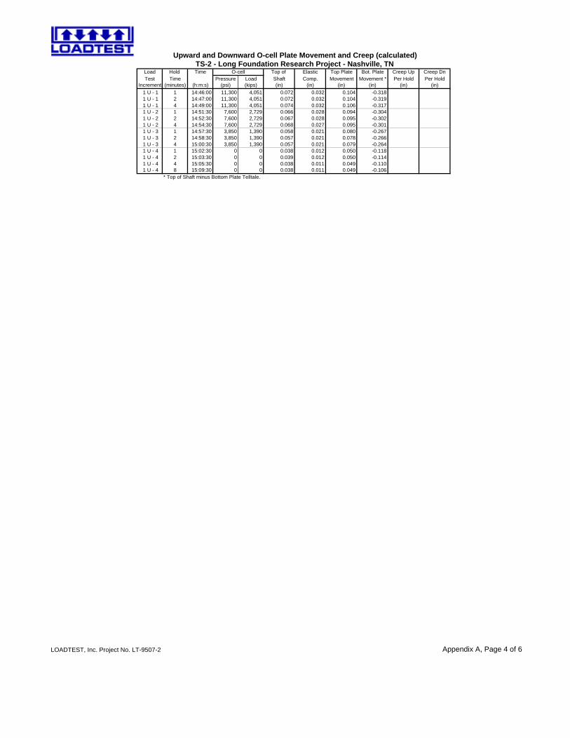
Upward and Downward O-cell Plate Movement and Creep (calculated)TS-2 - Long Foundation Research Project - Nashville, TN
LOADTEST, Inc. Project No. LT-9507-2 Appendix A, Page 3 of 6
Load Hold Time O-cell Top of Elastic Top Plate Bot. Plate Creep Up Creep DnTest Time Pressure Load Shaft Comp. Movement Movement * Per Hold Per Hold
Increment (minutes) (h:m:s) (psi) (kips) (in) (in) (in) (in) (in) (in)
Upward and Downward O-cell Plate Movement and Creep (calculated)TS-2 - Long Foundation Research Project - Nashville, TN
1 U - 1 1 14:46:00 11,300 4,051 0.072 0.032 0.104 -0.318 1 U - 1 2 14:47:00 11,300 4,051 0.072 0.032 0.104 -0.319 1 U - 1 4 14:49:00 11,300 4,051 0.074 0.032 0.106 -0.317 1 U - 2 1 14:51:30 7,600 2,729 0.066 0.028 0.094 -0.304 1 U - 2 2 14:52:30 7,600 2,729 0.067 0.028 0.095 -0.302 1 U - 2 4 14:54:30 7,600 2,729 0.068 0.027 0.095 -0.301 1 U - 3 1 14:57:30 3,850 1,390 0.058 0.021 0.080 -0.267 1 U - 3 2 14:58:30 3,850 1,390 0.057 0.021 0.078 -0.266 1 U - 3 4 15:00:30 3,850 1,390 0.057 0.021 0.079 -0.264 1 U - 4 1 15:02:30 0 0 0.038 0.012 0.050 -0.118 1 U - 4 2 15:03:30 0 0 0.039 0.012 0.050 -0.114 1 U - 4 4 15:05:30 0 0 0.038 0.011 0.049 -0.110 1 U - 4 8 15:09:30 0 0 0.038 0.011 0.049 -0.106
* Top of Shaft minus Bottom Plate Telltale.
LOADTEST, Inc. Project No. LT-9507-2 Appendix A, Page 4 of 6
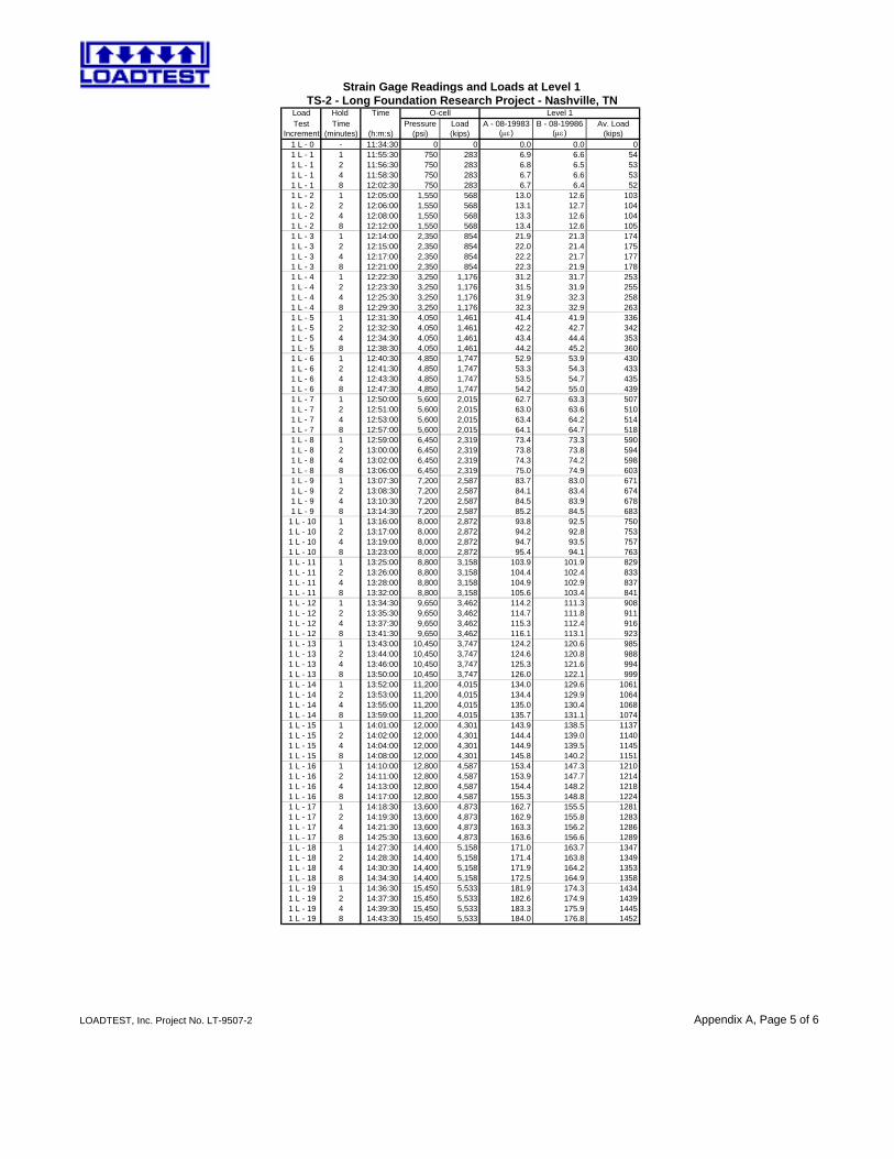
Load Hold Time O-cellTest Time Pressure Load A - 08-19983 B - 08-19986 Av. Load
Increment (minutes) (h:m:s) (psi) (kips) (με) (με) (kips) 1 L - 0 - 11:34:30 0 0 0.0 0.0 0 1 L - 1 1 11:55:30 750 283 6.9 6.6 54 1 L - 1 2 11:56:30 750 283 6.8 6.5 53 1 L - 1 4 11:58:30 750 283 6.7 6.6 53 1 L - 1 8 12:02:30 750 283 6.7 6.4 52 1 L - 2 1 12:05:00 1,550 568 13.0 12.6 103 1 L - 2 2 12:06:00 1,550 568 13.1 12.7 104 1 L - 2 4 12:08:00 1,550 568 13.3 12.6 104 1 L - 2 8 12:12:00 1,550 568 13.4 12.6 105 1 L - 3 1 12:14:00 2,350 854 21.9 21.3 174 1 L - 3 2 12:15:00 2,350 854 22.0 21.4 175 1 L - 3 4 12:17:00 2,350 854 22.2 21.7 177 1 L - 3 8 12:21:00 2,350 854 22.3 21.9 178 1 L - 4 1 12:22:30 3,250 1,176 31.2 31.7 253 1 L - 4 2 12:23:30 3,250 1,176 31.5 31.9 255 1 L - 4 4 12:25:30 3,250 1,176 31.9 32.3 258 1 L - 4 8 12:29:30 3,250 1,176 32.3 32.9 263 1 L - 5 1 12:31:30 4,050 1,461 41.4 41.9 336 1 L - 5 2 12:32:30 4,050 1,461 42.2 42.7 342 1 L - 5 4 12:34:30 4,050 1,461 43.4 44.4 353 1 L - 5 8 12:38:30 4,050 1,461 44.2 45.2 360 1 L - 6 1 12:40:30 4,850 1,747 52.9 53.9 430 1 L - 6 2 12:41:30 4,850 1,747 53.3 54.3 433 1 L - 6 4 12:43:30 4,850 1,747 53.5 54.7 435 1 L - 6 8 12:47:30 4,850 1,747 54.2 55.0 439 1 L - 7 1 12:50:00 5,600 2,015 62.7 63.3 507 1 L - 7 2 12:51:00 5,600 2,015 63.0 63.6 510 1 L - 7 4 12:53:00 5,600 2,015 63.4 64.2 514 1 L - 7 8 12:57:00 5,600 2,015 64.1 64.7 518 1 L - 8 1 12:59:00 6,450 2,319 73.4 73.3 590 1 L - 8 2 13:00:00 6,450 2,319 73.8 73.8 594 1 L - 8 4 13:02:00 6,450 2,319 74.3 74.2 598 1 L - 8 8 13:06:00 6,450 2,319 75.0 74.9 603 1 L - 9 1 13:07:30 7,200 2,587 83.7 83.0 671 1 L - 9 2 13:08:30 7,200 2,587 84.1 83.4 674 1 L - 9 4 13:10:30 7,200 2,587 84.5 83.9 678 1 L - 9 8 13:14:30 7,200 2,587 85.2 84.5 683
1 L - 10 1 13:16:00 8,000 2,872 93.8 92.5 750 1 L - 10 2 13:17:00 8,000 2,872 94.2 92.8 753 1 L - 10 4 13:19:00 8,000 2,872 94.7 93.5 757 1 L - 10 8 13:23:00 8,000 2,872 95.4 94.1 763 1 L - 11 1 13:25:00 8,800 3,158 103.9 101.9 829 1 L - 11 2 13:26:00 8,800 3,158 104.4 102.4 833 1 L - 11 4 13:28:00 8,800 3,158 104.9 102.9 837 1 L - 11 8 13:32:00 8,800 3,158 105.6 103.4 841 1 L - 12 1 13:34:30 9,650 3,462 114.2 111.3 908 1 L - 12 2 13:35:30 9,650 3,462 114.7 111.8 911 1 L - 12 4 13:37:30 9,650 3,462 115.3 112.4 916 1 L - 12 8 13:41:30 9,650 3,462 116.1 113.1 923 1 L - 13 1 13:43:00 10,450 3,747 124.2 120.6 985 1 L - 13 2 13:44:00 10,450 3,747 124.6 120.8 988 1 L - 13 4 13:46:00 10,450 3,747 125.3 121.6 994 1 L - 13 8 13:50:00 10,450 3,747 126.0 122.1 999 1 L - 14 1 13:52:00 11,200 4,015 134.0 129.6 1061 1 L - 14 2 13:53:00 11,200 4,015 134.4 129.9 1064 1 L - 14 4 13:55:00 11,200 4,015 135.0 130.4 1068 1 L - 14 8 13:59:00 11,200 4,015 135.7 131.1 1074 1 L - 15 1 14:01:00 12,000 4,301 143.9 138.5 1137 1 L - 15 2 14:02:00 12,000 4,301 144.4 139.0 1140 1 L - 15 4 14:04:00 12,000 4,301 144.9 139.5 1145 1 L - 15 8 14:08:00 12,000 4,301 145.8 140.2 1151 1 L - 16 1 14:10:00 12,800 4,587 153.4 147.3 1210 1 L - 16 2 14:11:00 12,800 4,587 153.9 147.7 1214 1 L - 16 4 14:13:00 12,800 4,587 154.4 148.2 1218 1 L - 16 8 14:17:00 12,800 4,587 155.3 148.8 1224 1 L - 17 1 14:18:30 13,600 4,873 162.7 155.5 1281 1 L - 17 2 14:19:30 13,600 4,873 162.9 155.8 1283 1 L - 17 4 14:21:30 13,600 4,873 163.3 156.2 1286 1 L - 17 8 14:25:30 13,600 4,873 163.6 156.6 1289 1 L - 18 1 14:27:30 14,400 5,158 171.0 163.7 1347 1 L - 18 2 14:28:30 14,400 5,158 171.4 163.8 1349 1 L - 18 4 14:30:30 14,400 5,158 171.9 164.2 1353 1 L - 18 8 14:34:30 14,400 5,158 172.5 164.9 1358 1 L - 19 1 14:36:30 15,450 5,533 181.9 174.3 1434 1 L - 19 2 14:37:30 15,450 5,533 182.6 174.9 1439 1 L - 19 4 14:39:30 15,450 5,533 183.3 175.9 1445 1 L - 19 8 14:43:30 15,450 5,533 184.0 176.8 1452
Strain Gage Readings and Loads at Level 1
Level 1TS-2 - Long Foundation Research Project - Nashville, TN
LOADTEST, Inc. Project No. LT-9507-2 Appendix A, Page 5 of 6
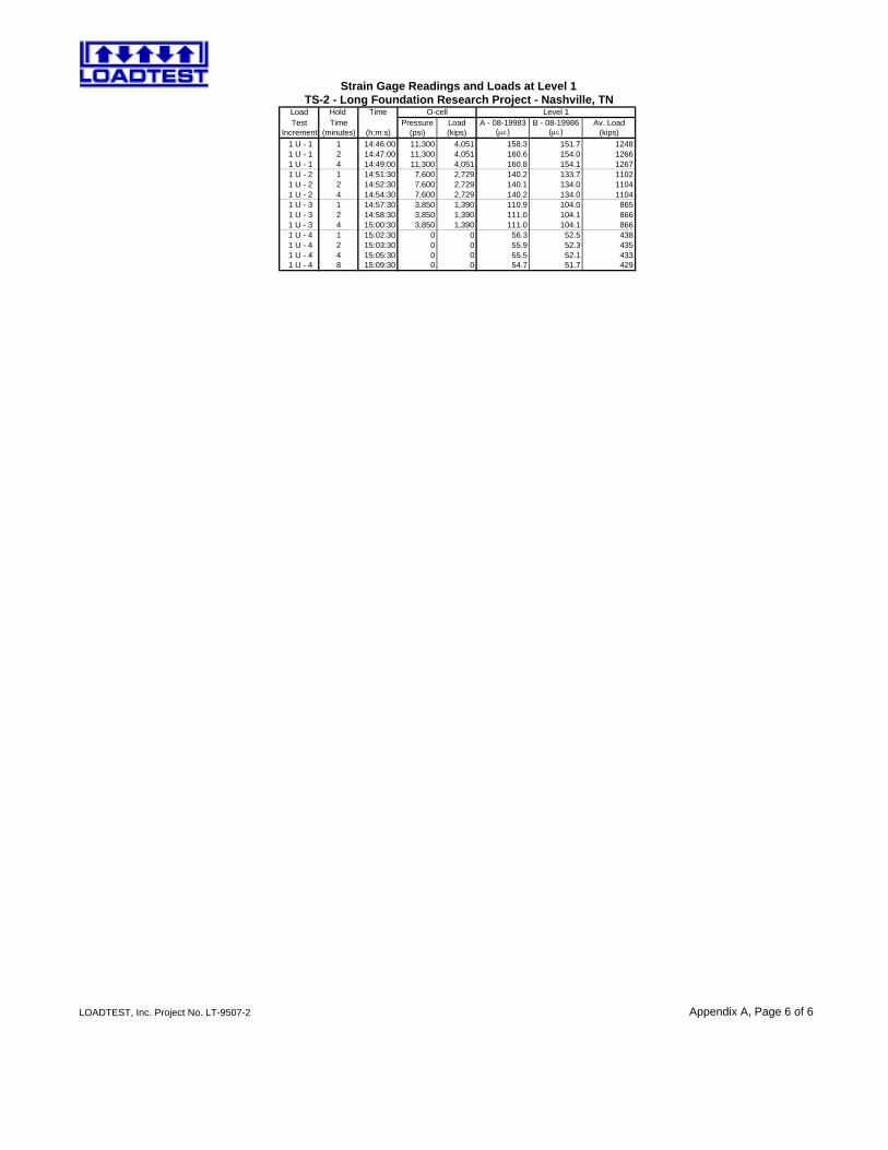
Load Hold Time O-cellTest Time Pressure Load A - 08-19983 B - 08-19986 Av. Load
Increment (minutes) (h:m:s) (psi) (kips) (με) (με) (kips)
Strain Gage Readings and Loads at Level 1
Level 1TS-2 - Long Foundation Research Project - Nashville, TN
1 U - 1 1 14:46:00 11,300 4,051 158.3 151.7 1248 1 U - 1 2 14:47:00 11,300 4,051 160.6 154.0 1266 1 U - 1 4 14:49:00 11,300 4,051 160.8 154.1 1267 1 U - 2 1 14:51:30 7,600 2,729 140.2 133.7 1102 1 U - 2 2 14:52:30 7,600 2,729 140.1 134.0 1104 1 U - 2 4 14:54:30 7,600 2,729 140.2 134.0 1104 1 U - 3 1 14:57:30 3,850 1,390 110.9 104.0 865 1 U - 3 2 14:58:30 3,850 1,390 111.0 104.1 866 1 U - 3 4 15:00:30 3,850 1,390 111.0 104.1 866 1 U - 4 1 15:02:30 0 0 56.3 52.5 438 1 U - 4 2 15:03:30 0 0 55.9 52.3 435 1 U - 4 4 15:05:30 0 0 55.5 52.1 433 1 U - 4 8 15:09:30 0 0 54.7 51.7 429
LOADTEST, Inc. Project No. LT-9507-2 Appendix A, Page 6 of 6
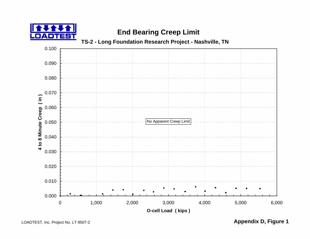
TS-2 - Long Foundation Research Project - Nashville, TN
LOADTEST, Inc. Project No. LT-9507-2 Appendix D, Figure 1
End Bearing Creep Limit
0.000
0.010
0.020
0.030
0.040
0.050
0.060
0.070
0.080
0.090
0.100
0 1,000 2,000 3,000 4,000 5,000 6,000
O-cell Load ( kips )
4 to
8 M
inut
e C
reep
( in
)
No Apparent Creep Limit

TS-2 - Long Foundation Research Project - Nashville, TN
LOADTEST, Inc. Project No. LT-9507-2 Appendix D, Figure 2
Side Shear Creep Limit
0.000
0.010
0.020
0.030
0.040
0.050
0.060
0.070
0.080
0.090
0.100
0 1,000 2,000 3,000 4,000 5,000 6,000
Net Load ( kips )
4 to
8 M
inut
e C
reep
( in
)
No Apparent Creep Limit