localizing firewall security policies -...
TRANSCRIPT
Localizing Firewall Security Policies
Pedro Adao1, Riccardo Focardi2,Flaminia L. Luccio3, and Joshua D. Guttman4
1 SQIG, Instituto de Telecomunicacoes, and Instituto Superior Tecnico, Universidadede Lisboa
2 University Ca’ Foscari, Venice and Cryptosense3 University Ca’ Foscari, Venice
4 The MITRE Corporation and Worcester Polytechnic Institute
Abstract. In complex networks, filters may be applied at different nodesto control how packets flow. In this paper, we study how to locate fil-tering functionality within a network. We show how to enforce a set ofsecurity goals while allowing maximal service subject to the security con-straints. To implement our results we present a tool that given a networkspecification and a set of control rules automatically localizes the filtersand generates configurations for all the firewalls in the network. Theseconfigurations are implemented using an extension of Mignis — an opensource tool to generate firewalls from declarative, semantically explicitconfigurations.Our contributions include a way to specify security goals for how packetstraverse the network; an algorithm to distribute filtering functionality todifferent nodes in the network to enforce a given set of security goals; anda proof that the results are compatible with a Mignis-based semanticsfor network behavior.
1 Introduction
Organizations have big and complicated networks. A university may have a net-work partitioned into dozens of subnets, separated either physically or as vlans.Although many of those subnets are very similar, for instance in requiring sim-ilar protection, others are quite different, for instance those that contain theuniversity’s human resources servers. The latter require far tighter protection.As another example, consider a corporation: some subnets contain public-facingmachines such as web servers or email servers; others support an engineeringdepartment or a sales department; and yet others contain the process-controlsystems that keep a factory operating. Thus, they should be governed by en-tirely different policies constraining what network flows can reach them, andfrom where.
Indeed, a network is a graph, in which the packets flow over the edges, andthe nodes may represent routers, end systems, and so forth. The security goalswe would like to enforce reflect this graph structure. They are essentially abouttrajectories, i.e. about where packets travel to get where they are going. Forinstance, a packet that reaches the process control system in the factory should
not have originated in the public internet. After all, some adversary may useit to insert a destructive command, regardless of how benign its source addressheader field looks when it arrives. Similarly, a packet that originates in the humanresources department should not traverse the public internet en route to the salesdepartment. It could be inspected while there, compromising information aboutsalaries within the company. A security goal may also restrict which packets maytake a particular trajectory, for instance only packet addressed to port 80 or 443on a web server.
In this paper, we introduce an expressive way to state security goals for packetflows. A security goal involves three network locations B,R,E, two assumptionproperties ψB , ψE , and one requirement property φ. Each of the properties char-acterizes packets—generally, their header fields—as found at a relevant location.The state of a packet may change as it traverses the network, so the propertiesapply to the packet as it appears when present at the corresponding locations.Network address translation (nat) is the packet-changing operation that we con-sider in this paper. However, the IP security protocols raise similar issues. Thesemantics of a goal concerns the packet flows that begin at B; end at E; andtraverse R. The goal requires that any packet that follows such a path mustsatisfy predicate φ when it is present at location R, assuming that it satisfiedψB at the beginning and ψE at the end.
We provide an algorithm to determine what filtering to do at the differentrouters in the network to enforce a given set of security goals. Our algorithmallows maximal functionality, delivering as rich a set of packets as are compatiblewith the policy, in the relevant case of packets that are not spoofed at theirorigin and not delivered promiscuously at the end. We also provide a rigoroussemantics of network behavior that allows us to prove that our algorithm issound. Finally, to implement our results we present a tool that, given a networkspecification and a set of control rules, uses this algorithm to automaticallylocalize the filters and to generate configurations for all the firewalls in thenetwork. These configurations are generated using Mignis+, an extension ofMignis — an open-source tool to generate firewalls from declarative, semanticallyexplicit configurations.
Related work Our approach is motivated by some previous work. We are in-terested in the defining behavioral security specifications in a network. In [6]Guttman and Herzog studied trajectory-based security goals, developing tech-niques to determine whether existing configurations enforce them correctly. Theirgoals were a less expressive class of two-region security goals, and they were un-able to generate configurations in addition to analyzing given ones. However,this paper follows the lead of [6] in regarding security goals as properties ofthe trajectories of packets as they traverse the network, formalized as a graph.Our network graphs and their executions are formalized in the frame model ofGuttman and Rowe [7].
Zhang et al. [11] focus more on the possible conflicts among policies at dif-ferent organizational levels, and less on their consequences given the topology of
2
the network. Our method is more general and is also designed to apply in thecase of devices that transform packets as they pass; we have particularly focusedon nat.
Kurshid et al. [8] demonstrate that it is possible, within software definednetworking, to check dynamically if global, behavioral properties are maintainedas invariants, for instance reachability for certain sorts of packets. We insteadmake no claims of real-time, on-line feasibility, but we offer a way to solve abroader range of security problems at design time.
Interesting work has also been done from a network programming languagepoint of view. The Frenetic project [5] deals with dynamic policies, but doesnot address network reachability or cyclicity problems; it is not clear how newlyadded constructs can interact with old ones. NetKAT [3] is equipped with asound and complete equational theory. However, while it might be possible toimplement our security goals, localization algorithm, and Mignis+ processingwithin the NetKAT framework, doing so would still require the analysis wepresent here.
Finally, much work has been devoted to firewall analysis, e.g. Margrave [9],which again lacks the distributed behavior of the network. Some automatic toolsfor testing of the firewall configuration enforcement have been proposed (see, e.g.,[2, 10]). These tools are very powerful in static networks, but they do neitherprevent consistency problems when new rules are added in the wrong order, noravoid completeness problems for some undefined packet rules.
Structure of the paper In Section 2 we present a model of our network asframes and executions, together with the different types of nodes (i.e., routers,network regions, and end hosts), and trajectories. In Section 3 we define thesecurity goals and the functionality goals. In Section 4 we describe how to as-sign filtering functionality to routers so as to enforce a set of region controlstatements. We first consider the case without nat. In Section 5 we first presentMignis+, an extension of Mignis, and we then present a tool that given a networkspecification and a set of region control rules automatically localizes the filtersand generates Mignis+ configurations for all the firewalls in the network, againassuming the nat-free case. We also describe a case study with automaticallygenerated configurations. In Section 6, we extend localization to cover nats. Weconclude in Section 7.
2 Network model
We model networks by frames and executions [7]. A location ` ∈ LO representsa network node and is equipped with a set of traces traces(`) defining its pos-sible local behaviors. We will use the words location and node interchangeably.A channel c ∈ CH allows the synchronous one-way transmission of messagesbetween the locations at its endpoints, sender(c) and rcpt(c). Each message alsocarries some data v ∈ D. An event e is an occurrence of a message on a chan-nel, so that msg(e) is the data transmitted and chan(e) is the channel on which
3

it occurs. Events with the same channel and event are indistinguishable, apartfrom the time at which they occur.
Definition 1 (Frame [7]). Let LO, CH,D, E be domains that we will call lo-cations, channels, data, and events, resp. Assume that LO, CH are finite.
1. A trace set T for a set of channels C ⊆ CH is a set of sequences of events〈e0, e1, . . . , ek〉 such that:(a) If ei is an event in t ∈ T , then chan(ei) ∈ C; and(b) T is prefix-closed.
2. A frame is a structure containing the domains and functions shown in Ta-ble 1 such that, for all ` ∈ LO, if traces(`) = T , then T is a trace set for the
Domains: LO, CH,D, E
sender : CH → LO rcpt : CH → LOchan : E → CH msg : E → D traces : LO → P(E∗)
Table 1. Signature of frames
set of channels C connected to `, namely C =
{c ∈ CH : sender(c) = ` or rcpt(c) = `}.
A trace of ` means a sequence t ∈ traces(`). ///
Each F determines a directed graph.
Definition 2 (Frame graphs [7]). If F is a frame, then the graph of F ,written gr(F), is the directed graph (V,E) whose vertices V are the locations LO,and such that there is an edge (`1, `2) ∈ E iff, for some c ∈ CH, sender(c) = `1and rcpt(c) = `2. ///
The execution model for frames relies on partially ordered sets of events. Theordering represents the occurs before relation, and events at a certain location `are required to be totally ordered and included in traces(`). Formally:
Definition 3 (Executions [7]). Let F be a frame, and B = (B,�) be a finite,partially ordered set of events, i.e. B ⊆ E and � is a partial order on B. Defineproj(B, `) =
{e ∈ B : sender(chan(e)) = ` or rcpt(chan(e)) = `}.
B is an execution of F , written B ∈ Exc(F), iff
1. proj(B, `) is linearly ordered by �, and2. proj(B, `) ∈ traces(`). ///
4
A finite linearly ordered set is a sequence. Thus, Clause 1 and the finitenesscondition ensure that proj(B, `) is a sequence. Clause 2 adds the requirementthat this sequence is a trace of `, for each choice of `.
We often write (c, p) for any event e such that chan(e) = c and msg(e) = p.Since different events may occur at different times, but involve the same datavalue p on the same channel c, this is strictly speaking an abuse of notation.
In this paper, the data values D are packets. We will refer to the sourceand destination addresses in a packet p as sa(p) and da(p). Packets have otherfamiliar properties such as a payload, a protocol and—if the protocol is tcp orudp—a source port and a destination port.
In networking, physical connections are nearly always bidirectional. A bidi-rectional connection will be represented by a pair of unidirectional channels.When convenient, we will refer to this pair as if it were a single bidirectionaledge.
2.1 Node behaviour
Nodes in a network can be of three types: (i) routers, (ii) network regions, and(iii) end hosts. Routers are connected to network regions (one or more), whereasend hosts are connected to a single network region, or possibly more than onenetwork region when the device has multiple interfaces.
End hosts are either promiscuous or chaste. A promiscuous host will acceptany packet sent to it, and may transmit any packet. A chaste host h has a set ofIP addresses IP(h), accepting only packets with destination address i ∈ IP(h),and transmitting only packets with source address i ∈ IP(h).
Given a network, one can easily construct a frame: the locations of the frameare the network nodes; for each (undirected) edge of the network, there is a pairof arcs, one in each direction. We provide traces(`) for each location:
Network region: A network region can only forward previously received pack-ets. Formally: (c1, p1), . . . , (ck, pk) ∈ traces(`) iff, ∀i ∈ [1, k], if sender(ci) = `,then there exists j < i : rcpt(cj) = `, pi = pj . Notice that a network regiondoes not guarantee to deliver every packet, nor to deliver it at most once.
End host: We have no constraint on traces for promiscuous hosts. For chasteones, we require that the source or destination address matches host’s ad-dresses for any packet it sends or receives: (c1, p1), . . . , (ck, pk) ∈ traces(h)iff ∀i ∈ [1, k] : sender(ci) = ` implies sa(pi) ∈ h and rcpt(ci) = ` impliesda(pi) ∈ h.
Router: When r is a router, then its behavior is determined by a firewall FWr :T ×CH×CH×P → P(P ). Intuitively, FWr takes a trace t ∈ T , representingthe history, an input and an output channel c and c′ and a packet p andreturns a (possibly empty) set of translations of p. Given history t, thesetranslations p′ represent all the possible ways in which p is accepted by thefirewall when p is received from c and p′ is delivered to c′. Given a firewallFWr and a routing function ρ, the behaviour of the router is determined asfollows:
5
p′ ∈ FW(t, c, c′, p) ρ(p′) = c′
〈t, σ〉;〈t.(c, p), σ ∪ (c′, p′)〉[filterin]
〈t, σ ] {(c, p)}〉;〈t.(c, p), σ〉 [routeout]
Router configuration is a pair 〈t, σ〉 where trace t represents the history and σis a buffer containing pairs (c, p) representing a packet p to be delivered overchannel c. Intuitively, rule filterin accepts packet p from channel c, addingit to t, only if there exists p′ ∈ FW(t, c, c′, p) that will be delivered overchannel c′. If this is the case, (c′, p′) is buffered in σ. Rule routeout takes apair (c, p) from the buffer and delivers packet p over channel c.We let t ∈ traces(r) iff 〈∅, ∅〉; . . .;〈t, σ〉.
Definition 4. We say that a frame F tightens a frame F ′ iff they share thesame graph, and for all routers r, and all t, c1, c2, p, FWr(t, c1, c2, p) ⊆ FW ′r(t, c1, c2, p).
2.2 Trajectories
A trajectory is a path that a packet may take as it traverses the network. Sincethe packet itself may change as it passes through a router with Network AddressTranslation, we need to define which events may belong together, i.e. when thepacket in a second event is the result of a NAT operation on the packet in thefirst event.
Definition 5. Two events e, e′ are associated if rcpt(chan(e)) = sender(chan(e′)) =` and either
1. ` is a network region and msg(e) = msg(e′); or2. ` is a router that allows a trace (c0, p0), . . . , (ck, pk) and ∃i, j : i < j such
that (ci, pi) = e ∧ (cj , pj) = e′, pj ∈ FWr(ti−1, ci, cj , pi) and ρ(pj) = cjwhere ti−1 = (c0, p0), . . . , (ci−1, pi−1). ///
The next result shows that packet association corresponds to the causal relationbetween inputs and outputs in the network.
Proposition 6. Let ` ∈ LO be a network region or router.
1. If e = (c, p), e′ = (c′, p′) are associated at ` then there exists a trace (c1, p1), . . . , (ck, pk) ∈traces(`) such that (ci, pi) = (c, p) ∧ (cj , pj) = (c′, p′) ∧ i < j;
2. ∀(c1, p1), . . . , (ck, pk) ∈ traces(`), if sender(cj) = ` then ∃i < j : rcpt(ci) = `and (ci, pi), (cj , pj) are associated at `.
Proof. For item (1): Assume ` is a network region. Then msg(e) = p = p′ =msg(e′). By the behaviour of network regions (cf. section 2.1) we get that (c, p), (c′, p′) ∈traces(`) which gives the thesis. If ` is a router, thesis is a direct consequence ofdefinition 5, item 2.
Item (2) can be trivially derived by the definition of traces for network regionand routers given in section 2.1.
6
A trajectory is a path that a packet may take from the point it originatesthrough network regions and routers, possibly reaching an end host at which itis received. A trajectory is successful if it originates with an end host whose IPaddresses include its (claimed) source address, and terminates with an end hostwhose IP addresses include its destination address. Thus, at the beginning it isnot spoofed, and at the end it is not promiscuously received.
Definition 7. Let B ∈ Exc(F) be an execution and let ~e = 〈e0, . . . ek〉 be asequence of events in B. We say that ~e is a trajectory in B iff
i. 0 ≤ i < j ≤ k implies ei ≺ ej;ii. either sender(chan(e0)) is promiscuous, or sa(msg(e0)) ∈ IP(sender(chan(e0)));
iii. either rcpt(chan(ek)) is promiscuous, or da(msg(ek)) ∈ IP(rcpt(chan(ek)));iv. if i < k, then rcpt(chan(ei)) is a network region or router, not an end host;v. for all i such that 0 ≤ i < k, ei, ei+1 are associated.
The trajectory ~e is successful iff
sa(msg(e0)) ∈ IP(sender(chan(e0)))
da(msg(ek)) ∈ IP(rcpt(chan(ek))) ///
The purpose of course of a network is to allow trajectories to succeed wheneverthat is compatible with the security goals of the network administrator.
When a packet p will be unchanged throughout a trajectory, for instancebecause the frame involves no network address translation, we often regard atrajectory as a pair consisting of the packet p together with a path π, where apath is a sequence of adjacent locations.
3 Goals for Security and Functionality
Each frame determines a set of trajectories, namely all of those compatible withthe router configurations and channels of the frame. In this section we explainhow to say which of those trajectories are good and which are bad, i.e. how toexpress security goals to govern a frame. In Section 4 we will provide an algorithmto determine router configurations that will enforce a given set of these goals.
3.1 Security Goals
We focus on three-region policy statements as security goals. We refer to themas region control statements. These take the following form, in which the regionvariables B,E,R each refer to end hosts and network regions, and ψB , ψE , andφ refer to sets of packets, determined by the header fields of the packet at thatstep in the trajectory:
Region control ψB@B → φ@R→ ψE@E: For every trajectory τ ,if τ starts at location B with a packet that satisfies ψB ,and τ ends at location E with a packet that satisfies ψE ,
7

then if location R is traversed in τ , the packet satisfies φ while at R.
In these region control statements, the sets ψB , ψE restrict the applicability ofthe security goal: They constrain a trajectory only if they are satisfied at thebeginning and end respectively. By contrast, φ is imposing a requirement, sincethe network must ensure it is satisfied when the trajectory reaches R. ThusψB , ψE are preconditions and φ is a postcondition, even though E is reachedlast.
We can express many useful properties by suitable choices of φ. For instance,we may want to ensure that a packet passing from B to E undergoes networkaddress translation properly, so that its source address at the time it traversesR is a routable address rather than a private address. We may want to assurethat packets from public regions B to a protected corporate region E have beenproperly filtered by the time they reach the corporate entry network R; thus,they should be tcp packets whose destinations are the publicly accessible weband email servers, and whose destination ports are the corresponding well-knownports. These provide examples of region control statements.
We will always assume that B 6= E, but there are many useful cases in whichthe intermediate region R equals one of the endpoints, i.e. B = R or R = E.We refer to these as two-region statements, since they just restrict the packetsthat can travel from B to E. When R = E, the statement says that whenevera packet travels from B to R, it must satisfy φ. Generally speaking, when thepurpose of the statement is to protect R from potentially harmful packets fromB, this form of the statement is useful; the property φ specifies which packetsare safe. The two-region formulas may also be used with R = B to protect Bagainst disclosure of certain packets to E. In this case, the property φ specifieswhich packets are non-sensitive.
Consider another type of security goal involving three regions:
Traversal control ψB@B � R� ψE@E: For every trajectory τ ,if τ starts at location B with a packet that satisfies ψB ,and τ ends at location E with a packet that satisfies ψE ,then location R is traversed in τ .
As an example of a traversal control statement, consider a corporate networkthat has packet inspection in a particular region R. Then we may want to ensurethat packets from public sources B to internal destinations E traverse R. Thereverse is also important in most cases, i.e. that packets from internal sources topublic destinations should traverse R.
Given a particular network, i.e. the graph underlying a frame, one strategyto enforce a traversal control statement is using region control statements. Wemay select a suitable cut set C of nodes between B and E where R ∈ C. We canthen implement the traversal control statement by stipulating the region controlstatements that for trajectories from B to E, if the packets traverse any memberof C \ {R}, then they satisfy the always-false header property false. That is, wehave the family of statements, one for each R′ 6= R in C:
ψB@B → false@R′ → ψE@E.
8

Given this, we will focus our attention on region control statements ψB@B →φ@R→ ψE@E.
A trajectory violates a region control statement if it has the correct beginningand end points, but violates the property φ while at R.
Definition 8. A trajectory ~e = 〈e0, . . . ek〉 is a counterexample to the regioncontrol statement ψB@B → φ@R→ ψE@E iff
1. sender(chan(e0)) = B and ψB(msg(e0));2. rcpt(chan(ek)) = E and ψE(msg(ek)); and3. for some i such that 0 ≤ i ≤ k, ¬φ(msg(ei)) and either sender(chan(ei)) = R
or rcpt(chan(ei)) = R.
When ~e is not a counterexample we say that ~e satisfies the region control state-ment ψB@B → φ@R → ψE@E. A frame F enforces ψB@B → φ@R → ψE@Eiff, whenever B ∈ Exc(F) is an execution of F and ~e is a trajectory in B, then ~esatisfies ψB@B → φ@R→ ψE@E. ///
3.2 Functionality Goals
Unlike security goals, which are mandatory, functionality may be a matter ofdegree. We choose to measure functionality by the set of packets that have asuccessful trajectory (Def. 7). A successful trajectory is one in which a packettravels from a non-spoofing producer to a consumer actually located at thedestination address of the packet. We focus on successful trajectories becausewe regard spoofing originators as intrinsically hostile, which is also the case forpromiscuous hosts that consume packets not addressed to them. We do not carewhether exactly the same paths are available for successful trajectories, but onlythat a successful trajectory should exist for as many packets as possible. Thus,we define:
Definition 9. Let F1 and F2 be two frames with the same underlying graph.F2 is at least as successful functionally as F1 iff, for all locations `0, `1, and
packets p0, p1, if there is a successful trajectory in which p0 starts at `0 and p1ends at `1 in F1, then there is also a successful trajectory for p0 starting at `0in which p1 ends at `1 in F2. ///
Given an underlying network topology, formalized as a graph, and a set of secu-rity goals, the acceptable frames are those that allow no counterexamples to thesecurity goals. Among those, one would like to construct a frame that is maximalin the ordering of successful functionality.
3.3 Forms of Goals
In the remainder of this paper, we will make an assumption about the sets ofsecurity goals we will consider. It is mere bookkeeping, since any set of goals canbe rewritten as a somewhat larger set of goals satisfying this assumption.
9

Assumption 10. In any set of security goals to be enforced, for any of thosegoals ψB@B → φ@R→ ψE@E, one of the following three cases holds:
1. for all packets p ∈ ψB , sa(p) ∈ IP(B), andfor all packets p ∈ ψE , da(p) ∈ IP(E);
2. for all packets p ∈ ψB , sa(p) 6∈ IP(B); or3. for all packets p ∈ ψE , da(p) 6∈ IP(E).
We refer to these goals as (1) success goals, (2) spoofing goals, and (3) promis-cuous delivery goals respectively. We will call goals of the second and third kindjointly promiscuity goals.
Success goals concern only successful trajectories in which the packet is notspoofed when created nor delivered promiscuously when consumed. Spoofinggoals consider only trajectories with spoofing at creation; promiscuous deliverygoals, trajectories with promiscuous delivery. The spoofing and promiscuous de-livery goals overlap. Any ψB@B → φ@R → ψE@E splits into at most threegoals, each of which applies in only one of these cases:
(ψB ∧ sa(p) ∈ IP(B))@B→ φ@R →(ψE ∧ da(p) ∈ IP(E))@E(ψB ∧ sa(p) 6∈ IP(B))@B→ φ@R →ψE@E
ψB@B→ φ@R →(ψE ∧ da(p) 6∈ IP(E))@E
This decomposition is useful, because when we treat goals of the first kind, wemust be careful to enforce them tightly. When preventing all counterexamples,we want to ensure that any non-counterexample that satisfies the assumptionsremains possible. These are successful trajectories, and a network that filtersthem unnecessarily is less successful functionally than it could be.
On the other hand, promiscuity goals, i.e. goals of the second and thirdkind, may be enforced cavalierly or brusquely, i.e. with less attention to allowingas many trajectories as possible compatible with the goals. A trajectory thatsatisfies the assumptions but is not a counterexample may be filtered out, sinceit would not be a successful trajectory. Thus, no functionality is sacrificed if itis discarded.
For this reason, in this paper we will focus on identifying how to enforce thesuccess goals precisely.
3.4 Case Study
We consider the network depicted in Figure 1 composed of three subnetworksSensitive, Trusted and Untrusted, two internal firewalls fw1 and fw2, andtwo frontier firewalls fw3 and fw4 connecting to the Internet. This representsa typical scenario where internal firewalls filter traffic among subnetworks whilefrontier firewalls filter traffic from/to the Internet.
In our example, Sensitive subnetwork contains important servers and dataand is connected to the Internet through the firewalls fw1 and fw3; Trustedsubnetwork is composed of trusted hosts that, for example, can access services
10
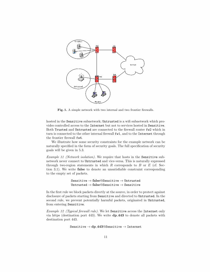
Fig. 1. A simple network with two internal and two frontier firewalls.
hosted in the Sensitive subnetwork; Untrusted is a wifi subnetwork which pro-vides controlled access to the Internet but not to services hosted in Sensitive.Both Trusted and Untrusted are connected to the firewall router fw2 which inturn is connected to the other internal firewall fw1, and to the Internet throughthe frontier firewall fw4.
We illustrate how some security constraints for the example network can benaturally specified in the form of security goals. The full specification of securitygoals will be given in 5.3.
Example 11 (Network isolation). We require that hosts in the Sensitive sub-network never connect to Untrusted and vice-versa. This is naturally expressedthrough two-region statements in which R corresponds to B or E (cf. Sec-tion 3.1). We write false to denote an unsatisfiable constraint correspondingto the empty set of packets.
Sensitive→ false@Sensitive→ Untrusted
Untrusted→ false@Sensitive→ Sensitive
In the first rule we block packets directly at the source, in order to protect againstdisclosure of packets starting from Sensitive and directed to Untrusted. In thesecond rule, we prevent potentially harmful packets, originated in Untrusted,from entering Sensitive.
Example 12 (Typical firewall rule). We let Sensitive access the Internet onlyvia https (destination port 443). We write dp 443 to denote all packets withdestination port 443.
Sensitive→ dp 443@Sensitive→ Internet
11
As above, we constrain packets directly at the source in order to prevent disclo-sure. In particular, notice that packets will never leave Sensitive unencrypted.
Example 13 (Traversal control and three region rules). Untrusted should accessthe Internet exclusively through fw3 on port 80. This is a form of traversalcontrol that can be compiled into region control rules by taking cut {fw3, fw4}and forbidding traversal of everything but fw3, i.e., fw4 (cf. Section 3.1). In areal setting, we might require this because fw3 is more powerful than fw4; forinstance, when it can handle complex (stateful) protocols and can audit whatthe untrusted users do.
Untrusted→ dp 80@fw3→ Internet
Untrusted→ false@fw4 → Internet
Notice that we cannot express the above goals using only two regions since theyspecify different requirements on the traversed intermediate nodes.
4 Localizing Security Policies Without Network AddressTranslation
In this section, we describe how to assign filtering functionality to routers soas to enforce a set of region control statements. For this, we will develop ourmethod based on a well-known matrix-based algorithm. To explain it, we willstart from the traditional version, which is applicable in the special case wherethe network has no nodes that perform nat. If there are nat nodes, we needto represent the effect of the various nat nodes traversed along a path as arelation that composes their individual effects; we will identify in Section 6 someassumptions on their network position and behavior.
When the network has no nodes configured to do network address translation,then every trajectory has the same packet throughout. Thus, only the positionof the packet changes as it progresses; its headers remain the same. This leadsto two simplifications. First, it is easy to compare a property of headers at onelocation with the effects it has at other locations; for instance, when packetsnot satisfying φ are discarded at some point of a path, the consequence is thatpackets reaching some subsequent point along that path satisfy φ. Second, non-simple paths, which may revisit the same node more than once, never createany new behavior. Since the only effect of a router may be to discard packets,the set of packets that can traverse a path is a subset of the packets that cantraverse any of its subpaths. Hence if any traversal provides a counterexampleto a security goal, then we may assume that it is the result of appending twosimple paths, one from the beginning region B to the intermediate region R,and another from region R to the end region E. In subsequent sections we willlift these simplifications, but the backbone of our analysis will be clearer in anexposition that can rely on them.
12

Specifying which packets to keep. We focus on the success goals. Fix aparticular pair of endpoints B,E. Thus, we have a collection of statements ofthe form ψB@B → φ0@R → ψE@E; because these are success goals, ψB , ψEensure that packets contain suitable addresses:
ψB(p) ⇒ sa(p) ∈ IP(B) and ψE(p) ⇒ da(p) ∈ IP(E).
Different goals in this collection may have different choices of ψB and ψE . Sincetrajectories do not alter packet properties in the no-NAT case, we can equiva-lently rewrite them to use uniform guards by replacing them with this equivalentform:
[sa(p)∈IP(B)]@B→ [ψB ∧ ψE ⇒ φ0]@R → [da(p)∈IP(E)]@E
Thus, we have essentially moved the variability in ψB , ψE from the endpointsto R, creating a new formula φ1 at R. Thus, we will now assume that all B,Egoals have the same guard formulas at B and E, namely sa(p) ∈ IP(B) andda(p) ∈ IP(E). We will however keep writing φ for the generic form of a formularequired at the intermediate location R, even if it has been rewritten as shownabove.
Fix a choice of B,E. We will write PB,E for the set of packets with sa(p) ∈IP(B) and da(p) ∈ IP(E).
Definition 14. Suppose given a non-empty collection G of success goals rewrit-ten if necessary to produce uniform ψB , ψE. We define PrmtB,E(`) to be:
PrmtB,E(`) = PB,E ∩⋂φ`
φ`,
taking the intersection over all of the φ` such that a formula ψB@B → φ`@`→ψE@E appears in G. We may write Prmt(`) whenever B,E are clear from thecontext. ///
Thus, PrmtB,E(`) always includes the packets which are permitted to appearin `, as part of a successful trajectory from B to E. A packet is worth keepingat a location if it can use that location to get from B to E along some path thattraverses only locations at which it is permitted:
Definition 15 (Keep). Packet p ∈ PB,E is worth keeping along path π fromB to E iff, for every ` along π, p ∈ PrmtB,E(`).
Packet p ∈ PB,E is worth keeping from B to E at ` iff there exists some πsuch that π leads from B to E and traverses `, and p is worth keeping alongpath π.
We write KEEPB,E(`) for the set of p ∈ PB,E worth keeping from B to Eat `. We write KEEP(`) whenever B and E are clear from the context. ///
13
If a packet is permitted at all locations along some path from B to E that passesthrough `, then it is certainly permitted at location `:
Lemma 16. If p ∈ KEEPB,E(`), then p ∈ PrmtB,E(`).
Notice that a packet going from B to E is permitted at a given location ` onlyif it does not contradict any of the possible region control rules. So, for a packetto be worth keeping from B to E, it is enough if there is a single path π inwhich p is allowed to traverse all locations of π. However, to ensure that packetsuse these locations only to follow permissible paths requires the filters we willgenerate in Def. 18.
By the second of the simplifications mentioned at the beginning of Section 4,this definition is unchanged whether we consider all π or only the paths π inwhich the part before ` is simple, and the part after is too.
The direct way of computing KEEP(`) would thus be to examine every simplepath π1 from B to `, and every path π2 from ` to E, taking an intersection ofthe p ∈ PB,E permitted at every step of π_1 π2, and combining the results viaa union over all choices of π1 and π2. We present a simpler way using matrixmultiplication in Section 4.
Combining the keep sets for different endpoints. When we define KEEPB,E ,we work only with packets p ∈ PB,E . We will now assume:
Assumption 17. For all locations `, `′, if ` 6= `′, then IP(`) ∩ IP(`′) = ∅.
Hence these packets are disjoint from the packets of interest when computingany other KEEPB′,E′ . Thus, we may simply repeat the computation for eachdistinct pair B,E, accumulating the union of the KEEP sets for each `.
The resulting union consists of all packets that may traverse ` along a suc-cessful trajectory from the stated source to the stated destination without en-countering a location at which it is not permitted. Thus, we may define, for agiven set of goal statements G:
KEEP∗(`) =⋃B,E
KEEPB,E(`) (1)
We would like now to filter packets as they are passing from one location toanother location at which they should not be kept, i.e., we should discard thecomplement of KEEP∗(`
′) along any edge a : ` → `′. We summarize this ideain filters for the arcs a : ` → `′. Since below we use the complement, the set ofpackets that should be accepted along a, we formalize that as the accept filteraf.
Definition 18. The acceptance filter af is the function from arcs to sets ofpackets defined af(a) = KEEP∗(`
′), when a : ` → `′ is an arc from ` to `′. Wealso write af(`, `′) for af(a).
We define the redundant filter of an arc a : ` → `′ from ` to `′ as rf`,`′ =KEEP∗(`) ∩ KEEP∗(`
′). ///
14

Intuitively, af assumes that all firewalls cooperate, while rf redundantly re-enforces filtering at each firewall. Thus, when all firewalls behave according totheir specifications, af and rf have exactly the same effect. However, rf is morerobust if any firewalls may be compromised.
As mentioned before, we always require that B 6= E in any goal statement.
Theorem 19 (Filter security). Let G be a non-empty collection of successgoals, for a nat-free frame. Let ~e = 〈e0, . . . ek〉 be a success trajectory such thatsender(chan(e0)) = B and rcpt(chan(ek)) = E. Suppose that, for all 0 ≤ i ≤ kand locations `, `′, if sender(chan(ei)) = ` and rcpt(chan(ei)) = `′, then
Case 1. msg(ei) ∈ af(`, `′)
Case 2. msg(ei) ∈ rf(`, `′).
Then ~e satisfies all of the success goals ψB@B → φ@R→ ψE@E in G.
Proof. First, since we are assuming that there are no nats, we have a p suchthat, for all i, msg(ei) = p. Since ~e is a success trajectory, sa(p) ∈ IP(B) andda(p) ∈ IP(E).
1. First suppose that R 6= B. If ~e never traverses R, then the success goal isvacuously satisfied. So let ei be the earliest event such that rcpt(chan(ei)) = R.By the definition of af, p ∈ KEEP(R). By Lemma 16, p ∈ Prmt(R). So p satisfiesφ.
If R = B, then we use the fact that B 6= E. Thus, p traverses at least one edgeto rcpt(chan(e0)). Hence, p = msg(e0) ∈ af(B, rcpt(chan(e0))). By the definition,p ∈ KEEP(rcpt(chan(e0))). Hence, there is at least one path π that traversesrcpt(chan(e0)) such that p ∈ Prmt(`) for every ` along π. But B appears at thebeginning of every path (including π) from B to E. Thus, p ∈ Prmt(B), so psatisfies φ.
2. The preceding argument applies a fortiori, since rf(a) ⊆ af(a) for every a.
Moreover, af is maximally successful among all filtering strategies that en-force the success goals. That is, any assignment of filters that permits additionalsuccessful trajectories allows counterexamples to some goal. Indeed, we preventa successful trajectory only if that trajectory is incompatible with the securitygoals.
Theorem 20 (Maximal success). Suppose that f is a function from arcs tosets of packets, and for all a : `→ `′, either
Case (a) af(a) ⊆ f(a), or else
Case (b) rf(a) ⊆ f(a).
Suppose that τ is a successful trajectory compatible with f but not with the se-lected filters af or rf. Then τ is a counterexample to some success goal.
15

Proof. Assuming case (a): Since τ is incompatible with af, it traverses someedge a : ` → `′ such that, letting the packet of τ be p, p ∈ KEEP∗(`) butp 6∈ KEEP∗(`
′). Therefore there is no path π from the start of τ to its endpointthat traverses `′ such that p ∈ Prmt(`1) for all `1 along π.
Assuming case (b): Since τ is incompatible with rf, it traverses some edgea : `→ `′ such that, letting the packet of τ be p, p 6∈ KEEP∗(`) or p 6∈ KEEP∗(`
′).Therefore, letting `′′ be either ` or `′, there is no path π from the start of τ toits endpoint that traverses `′′ such that p ∈ Prmt(`1) for all `1 along π.
Hence, in either case (a) or case (b), the sequence of locations traversed in τis not such a path. Thus, τ is a counterexample to some goal between theseendpoints.
Computing the sets to keep. Observe that sets of packets form a booleanalgebra, and therefore surely a ring where ∩ is the multiplication and ∪ is theaddition. In particular, ∩ distributes over ∪. Thus, we can form matrices ofsets, and matrix multiplication accumulates the ∪ of the ∩s of correspondingelements. I.e. if we define the inner product ~a ·~b to be:⋃
i
(a[i] ∩ b[i]),
then the matrix multiplication AB yields C, where Cij = ~ai ·~bj using the ith
row vector of A and the jth column vector of B. Let:
A be the adjacency matrix for the graph, where if there is an edge from node ito node j, then the entry Aij is the top element, i.e. the set of all packets.Aij = ∅ if i, j are not adjacent.
K be the diagonal matrix with entries Ki,i = Prmt(i).
We want to compute the matrices Rchm such that each entry
Rchmi,j is the set of p ∈ PB,E that can reach node j from node i along a path oflength ≤ m while traversing only locations n such that p ∈ Prmt(n).
We claim:
Rch0 = K, since paths of length 0 lead only from i to i, and Ki,i is the set ofpackets permitted there.
Rch1 = K + (KAK). A path of length ≤ 1 is either empty or else it takes onestep from i to an adjacent location j; moreover, the packet should satisfyPrmt(i) before the step and Prmt(j) after it.
Rch(2m) = (Rchm Rchm), since the paths of length ≤ 2m are just the paths thatdivide into two paths of length ≤ m, respectively ending and beginning atthe same node k.
Since every (simple) path visits each node at most once, it is no longer than |N |,the cardinality of the set of nodes. As remarked above, non-simple paths allowno additional packets, since they subject the packets to additional constraints.Thus, the sequence stabilizes by Rchb where b = 21+log2 |N |, and we define:
16

Rch = Rchb is the fixed point of Rchm.
Observe that this computation requires O(log2 |N |) matrix multiplications toreach its fixed point, and is thus tractable for large |N |, assuming that theunderlying ring operations on sets are tractable.
Lemma 21. For a configuration without nat or other packet transformations,KEEP(i) = RchB,i ∩ Rchi,E.
Proof. Set RchB,i∩Rchi,E contains all packets p ∈ PB,E that can reach i from Band then E from i while traversing only locations n such that p ∈ PrmtB,E(n).Thus, p belongs to RchB,i ∩ Rchi,E if and only if p ∈ PB,E and there existssome π such that π leads from B to E and traverses i, and for every ` along π,p ∈ PrmtB,E(`). By Definition 15 we directly obtain RchB,i ∩Rchi,E = KEEP(i).
Tightening given filters. Suppose we want to calculate the success filters rel-ative to some given filters f(e, d), where e is an edge, d is a direction (inboundvs. outbound), and the resulting value f(e, d) is the set of packets we will permitto travel along edge e in direction d. We would like to derive maximally permis-sive filters that tighten the given ones and enforce the goal statements. To doso, instead of starting with the adjacency matrix A, we define Af to have theentry f(e, d) in position Afi,j if edge e leads from location i to location j whentraversed in direction d. Like A, it contains the empty set whenever i and j arenot adjacent. The successive matrices Rch0,Rch1, . . . ,Rchm are now computedas before, starting with matrix Af .
For instance, we might like to use this idea to protect terminal networks—meaning a network segment ` with just one connection to the remainder of thenetwork—from inappropriate packets. Suppose that a ` contains IP addressesIP(`). Thus, the remainder of the network has the complementary set of IPaddresses IP(`).
Then we would like to permit packets p outbound only if sa(p) ∈ IP(`) andda(p) ∈ IP(`). We would like to permit packets p inbound only if da(p) ∈ IP(`)and sa(p) ∈ IP(`). Edges that do not connect a terminal network retain theiroriginal specification of allowing all packets. This leads to a useful policy Af tostart from in computing the sets Rch.
Firewall Configuration. We now define firewall behaviour FW based on theKEEP∗ sets. We consider the case of nodes connected to at least one firewall or,in other words, we assume that any edge in the network has filtering capabilities.
Definition 22. For each firewall `f , consider any input and output channels ciand co such that rcpt(ci) = `f and sender(co) = `f . Let `i and `o be the twolocations connected to ci and co, i.e., `i = sender(ci), rcpt(co) = `o. Then wedefine a firewall as:
FWa(t, ci, co, p) ,
{{p} if p ∈ af`i,`f ∩ af`f ,`o{} otherwise
17
and, similarly, a redundant firewall as:
FWr(t, ci, co, p) ,
{{p} if p ∈ rf`i,`f ∩ rf`f ,`o{} otherwise ///
Intuitively, a firewall without network address translation accepts a packet pwhenever p is accepted on both the input and the output channels, i.e., wheneverp belongs to af`i,`f ∩ af`f ,`o , or to rf`i,`f ∩ rf`f ,`o for the redundant firewall.
Theorem 23. Let G be a non-empty collection of success goals. If each channelis connected to at least one router and the behaviour of all routers is determinedby FWa(t, ci, co, p) or FWr(t, ci, co, p), then frame F enforces G.
Proof. Suppose that, in order to get a contradiction, the firewalls are definedas above but frame F does not enforce some goal of G. This means that thereis a goal ψB@B → φ@R → ψE@E, an execution B of F , and a trajectory~e = 〈e0, . . . ek〉 in B such that ~e is a counterexample for this goal. By Theorem 19,there exists 0 ≤ i ≤ k such that msg(ei) 6∈ af(`, `′) and msg(ei) 6∈ rf(`, `′)
Recall that B and E are required to be end hosts and cannot be routers. Byhypothesis we have that any edge of F has at least one firewall so, if the firewallis located at ` we consider the incoming event ei−1 (from `i to `) and we obtainFWa(t, chan(ei−1), chan(ei), p) = {}, FWr(t, chan(ei−1), chan(ei), p) = {} asp /∈ af(`i, `)∩af(`, `′), p /∈ rf(`i, `)∩ rf(`, `′); if the firewall is located at `′ we con-sider the outgoing event ei+1 (from `′ to `o) and again FWa(t, chan(ei), chan(ei + 1), p) ={} and FWr(t, chan(ei), chan(ei + 1), p) = {} , as p /∈ af(`, `′) ∩ af(`′, `o), p /∈rf(`, `′) ∩ rf(`′, `o).
In both cases, the router behaviour defined in Section 2 enforces that the pis blocked hence we get a contradiction on the existence of the counterexampletrajectory.
Example 24 (Localization of traversal control). Consider again the traversal con-trol rules of Example 13:
Untrusted→ dp 80@fw3→ Internet
Untrusted→ false@fw4 → Internet
We show how they are localized using the redundant firewall FWr(t, ci, co, p).We only report cases where we have nonempty set of packets and we write Un
for Untrusted and Int for Internet:
FW1r(t, (fw2, fw1), (fw1, fw3), p) ,
{{p} if dp 80(p){} otherwise
FW2r(t, (Un, fw2), (fw2, fw1), p) ,
{{p} if dp 80(p){} otherwise
FW3r(t, (fw1, fw3), (fw3, Int), p) ,
{{p} if dp 80(p){} otherwise
FW4r(t, ci, co, p) , {}
18
We notice that the above rules enable the path Untrusted, fw2, fw1, fw3,Internet for packets with destination port 80. Packets trying to reach fw4 fromfw2 are dropped in fw2.
5 Semantic Based Implementation
The theory developed so far considers a very general notion of firewall FWwhose behaviour depends on the firewall history and on the actual input andoutput channels. We now show how this general notion can be implementedusing an extension of Mignis [1], a semantic based tool for firewall configurationin Linux systems. Mignis has a formal semantics that permits us to formallyprove correctness with respect to our frame semantics and, at the same time, isprovided with an open-source compiler,5 that will allow us to produce workingLinux firewalls, as illustrated in Section 5.2. Notice that Mignis is a generalfirewall language and is not tailored only to Linux systems. Thus, in principle,Mignis could also generate configurations for other firewall systems.
5.1 Mignis and its Semantics
Mignis [1] is a declarative specification language in which the order of rules doesnot matter. This makes the specification of a firewall very close to its semantics:a packet goes through (possibly translated) only if it matches a positive rule andis not explicitly denied. This allows administrators to write and inspect rulesindependently of the order in which they are specified. Moreover, the declarativeapproach makes it easy to detect possible conflicts and redundancies and toquery for a subset of the specification involving specific hosts. Mignis supportsNetwork Address Translation (NAT), i.e., it allows the translation of the sourceand destination addresses of a packet while it crosses the firewall, and it appliesthe translation consistently to all packets belonging to the same connection.
Mignis rules are defined in terms of address ranges n. An address range n is apair consisting of a set of IP addresses and a set of ports, denoted IP(n):port(n).Given an address addr, we write addr ∈ n to denote port(addr) ∈ port(n),if port(addr) is defined, and IP(addr) ∈ IP(n). Notice that if addr does notspecify a port (for example in ICMP packets) we only check if the IP address isin the range. We will use the wildcard ∗ to denote any possible address or portor address range, and ε to denote a special range consisting of a special addressεaddr used to note void translations.
Syntax We present a version of Mignis (that we call Mignis+) that extends theoriginal one in various respects: (i) rules are localized on channels CH in order toallow for packet filtering that depends on the network topology; (ii) packets onestablished connections are not accepted by default; (iii) rules are all positive.Mignis+ is slightly more complex to use but strictly more expressive than the
5 https://github.com/secgroup/Mignis
19
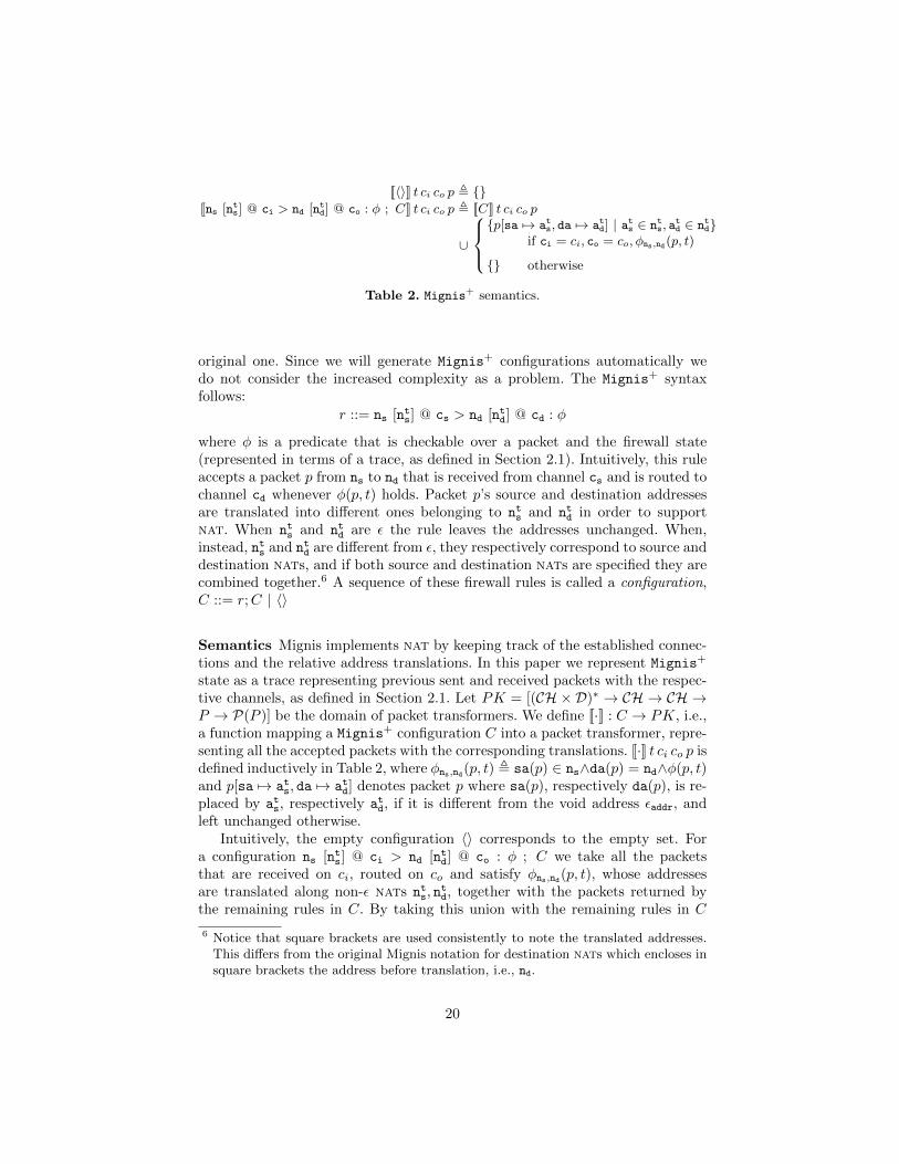
[[〈〉]] t ci co p , {}[[ns [nts] @ ci > nd [ntd] @ co : φ ; C]] t ci co p , [[C]] t ci co p
∪
{p[sa 7→ ats, da 7→ atd] | ats ∈ nts, a
td ∈ ntd}
if ci = ci, co = co, φns,nd(p, t)
{} otherwise
Table 2. Mignis+ semantics.
original one. Since we will generate Mignis+ configurations automatically wedo not consider the increased complexity as a problem. The Mignis+ syntaxfollows:
r ::= ns [nts] @ cs > nd [ntd] @ cd : φ
where φ is a predicate that is checkable over a packet and the firewall state(represented in terms of a trace, as defined in Section 2.1). Intuitively, this ruleaccepts a packet p from ns to nd that is received from channel cs and is routed tochannel cd whenever φ(p, t) holds. Packet p’s source and destination addressesare translated into different ones belonging to nts and ntd in order to supportnat. When nts and ntd are ε the rule leaves the addresses unchanged. When,instead, nts and ntd are different from ε, they respectively correspond to source anddestination nats, and if both source and destination nats are specified they arecombined together.6 A sequence of these firewall rules is called a configuration,C ::= r;C | 〈〉
Semantics Mignis implements nat by keeping track of the established connec-tions and the relative address translations. In this paper we represent Mignis+
state as a trace representing previous sent and received packets with the respec-tive channels, as defined in Section 2.1. Let PK = [(CH × D)∗ → CH → CH →P → P(P )] be the domain of packet transformers. We define [[·]] : C → PK, i.e.,a function mapping a Mignis+ configuration C into a packet transformer, repre-senting all the accepted packets with the corresponding translations. [[·]] t ci co p isdefined inductively in Table 2, where φns,nd(p, t) , sa(p) ∈ ns∧da(p) = nd∧φ(p, t)and p[sa 7→ ats, da 7→ atd] denotes packet p where sa(p), respectively da(p), is re-placed by ats, respectively atd, if it is different from the void address εaddr, andleft unchanged otherwise.
Intuitively, the empty configuration 〈〉 corresponds to the empty set. Fora configuration ns [nts] @ ci > nd [ntd] @ co : φ ; C we take all the packetsthat are received on ci, routed on co and satisfy φns,nd(p, t), whose addressesare translated along non-ε nats nts, n
td, together with the packets returned by
the remaining rules in C. By taking this union with the remaining rules in C
6 Notice that square brackets are used consistently to note the translated addresses.This differs from the original Mignis notation for destination nats which encloses insquare brackets the address before translation, i.e., nd.
20

we are indeed considering that there is no ordering in the rules of a Mignis+
configuration.
Definition 25 (Mignis+ firewall). Given a Mignis+ configuration C, we letFW(t, c, c′, p) , [[C]] t c c′ p.
Example 26. Consider a destination nat that translates all tcp incoming pack-ets from interface eth0 directed to 192.168.0.1 port 80 on interface eth1, intoaddress 192.168.0.100 on the same port. In Mignis+ this is specified through aconfiguration C composed of a single rule:
∗@eth0 > 192.168.0.1:80@eth1 [192.168.0.100:80] : tcp
where we omit writing the void [εaddr] source nat, for readability, and where tcpcorresponds to a predicate that holds if and only if p is a tcp packet. We have:
[[C]] t ci co p = {p[da 7→ 192.168.0.100:80]}
if da(p) = 192.168.0.1:80, ci = eth0, co = eth1, tcp(p). This firewall will acceptany tcp packet from eth0 with destination 192.168.0.1:80 on eth1 and will trans-late its destination to 192.168.0.100:80. For example, let p be a tcp packet withsource 1.2.3.4:5656 and destination 192.168.0.1:80. We have [[C]] t eth0 eth1 p ={p[da 7→ 192.168.0.100:80]}. Notice that packet being tcp is independent of thefirewall history t, so firewall semantics does not depend on t in this specificexample.
5.2 A Tool for Firewall Localization
We have implemented a tool that given a network specification and a set ofregion control rules automatically localizes the filters and generates Mignis+
configurations for all the firewalls in the network. We have also modified theoriginal Mignis compiler by incorporating the extensions illustrated in section 5.1in order to produce the actual Linux firewall (Netfilter) configurations. The toolis implemented in Python3.
Network We consider a network consisting of firewalls and end hosts, and weassume that each channel has at least one firewall endpoint. This ensures thatall edges can filter packets.
Constraints Given rule ψB@B → φ@R → ψE@E, we specify constraintsψB , ψE and φ as Boolean expressions over variables representing the followingfacts:
Source and destination address whenever a packet has source or destina-tion address of end host h, written sa h and da h, respectively;
Source and destination port whenever a packet has a source or destinationport n, written sp n and dp n, respectively;
21

Protocol whenever packet protocol is p, written pr p;Established whenever a packet belongs to an established connection, written
est.
For example, sp 443 & est requires that the source port is 443, and that packetsbelong to an established connection. This is a typical example of a responsefrom a SSL web server. Notice that we use notations &, | and ∼ to representBoolean AND, OR and NOT, respectively. Rules apply only to non-spoofed,non-promiscuous packets. This is automatically enforced by requiring ψB&sa B
and ψE&sa E in place of ψB and ψE .
Localization We compute localization as described in section 4. At the mo-ment the prototype only supports the case without NATs described in section 4.We leave the extension to NATs as a future work. Constraints are representedas reduced, ordered binary decision diagrams (ROBDD) [4]. We base our im-plementation on the Python EDA library that supports both Boolean algebraand ROBDDs.7 The advantage of adopting ROBDD representation is that itis a canonical form and makes it very efficient to compute equivalence betweenBoolean expressions, which is useful to determine when the computation of Rchstabilizes. Set union and intersection used for localization in section 4 naturallybecome OR and AND Boolean operators over ROBDDs.
Firewall configuration Once we obtain FWa(t, ci, co, p) or FWr(t, ci, co, p)in the form of a Boolean expression we generate Mignis+ configurations byinstantiating the expression with the source and destination addresses of anypossible end host, and by computing the solutions of the obtained boolean ex-pression. It is worth noticing that Python EDA transparently invokes PicoSATsolver 8 to efficiently solve a Boolean expression. Solutions are then translatedinto constraints over ports, protocol and established state.
5.3 Case Study in Detail
We now define the security goals for the example network of Figure 1 and dis-cussed in Section 3.4.
As already mentioned, firewalls usually keep track of established connectionsso that packets belonging to the same connections are not filtered. This is partic-ularly useful to enable bidirectional communication without necessarily openingthe firewall bidirectionally to a new connection: it is enough to open the firewallin one direction and let established packets come back. We write est to notethat a packet is established (cf. Section 5.2). While specifying rules, we proceedpair by pair, defining the rules and their established counterpart (when needed)at the same time.
7 http://pyeda.readthedocs.org/8 http://fmv.jku.at/picosat/
22

Hosts in the Sensitive and Trusted subnetworks should never connect toUntrusted and vice-versa. This is naturally expressed through two-region state-ments (cf. Example 11, Section 3.1):
Sensitive→ false@Sensitive→ Untrusted
Untrusted→ false@Sensitive→ Sensitive
Trusted→ false@Trusted → Untrusted
Untrusted→ false@Trusted → Trusted
Hosts in the Sensitive subnetwork should never connect to Trusted, while hostsfrom Trusted network can access Sensitive via ssh through fw1 without passingthrough the Internet as this would unnecessarily expose network connectionsto attacks. Notice that we filter packets from Sensitive to Trusted only if theydo not belong to established ssh connections:
Trusted→ dp 22@Sensitive → Sensitive
Sensitive→ (sp 22&est)@Sensitive→ Trusted
Trusted→ false@Internet → Sensitive
Sensitive→ false@Internet → Trusted
Sensitive should access the Internet only via https (destination port 443),while Internet hosts should never start new connections towards Sensitive:
Sensitive→ dp 443@Sensitive → Internet
Internet→ (sp 443&est)@Sensitive→ Sensitive
Trusted has full access to the Internet and from the Internet we give accessto Trusted only via ssh (port 22). When full access is granted, we do not specifyany region control statement, but we still need to let established packets gothrough:
Internet→ (dp 22|est)@Trusted→ Trusted
Untrusted should access the Internet exclusively through fw3 on port 80. Thisis a form of traversal control that can be compiled into region control rules bytaking cut {fw3, fw4} and forbidding traversal of everything but fw3, i.e., fw4(cf. Example 13, Section 3.1). Internet should never access Untrusted:
Untrusted→ dp 80@fw3 → Internet
Internet→ (sp 80&est)@fw3→ Untrusted
Untrusted→ false@fw4 → Internet
Internet→ false@fw4 → Untrusted
Localizing filtering Table 3 in the Appendix reports the output of the lo-calization tool that automatically generated the Mignis+ configuration for thefour firewalls according to FWr(t, ci, co, p). Channels/interfaces are named withprefix if to distinguish them from network end hosts. For example, the firstgroup of rules for firewall fw1
23

Sensitive@if_Sensitive:22 > Trusted@if_fw2 | -m ...
Sensitive@if_Sensitive > Internet@if_fw2:443
refer to interfaces if Sensitive and if fw2, i.e., packets coming from the chan-nel connecting Sensitive to fw1 and delivered over the channel from fw1 tofw2. Established requirement is translated into the low level syntax of Linuxfirewall:
-m state --state ESTABLISHED,RELATED
We can see that, on these two channels, firewall fw1 only allows packets fromSensitive to Trusted on established ssh connections and new https connectionsfrom Sensitive to Internet, as required by the region control rules:
Sensitive→ (sp 22&est)@Sensitive→ Trusted
Sensitive→ dp 443@Sensitive → Internet
We illustrate in detail how the following rules, permitting access from Unstrusted
to Internet only on port 80 through fw3, are localized in the firewalls:
Untrusted→ dp 80@fw3 → Internet
Internet→ (sp 80&est)@fw3→ Untrusted
Untrusted→ false@fw4 → Internet
Internet→ false@fw4 → Untrusted
The relevant rules are:
FIREWALL fw1
Untrusted@if_fw2 > Internet@if_fw3:80
Internet@if_fw3:80 > Untrusted@if_fw2 | -m ...
FIREWALL fw2
Untrusted@if_Untrusted > Internet@if_fw1:80
Internet@if_fw1:80 > Untrusted@if_Untrusted | -m ...
FIREWALL fw3
Internet@if_Internet:80 > Untrusted@if_fw1 | -m ...
Untrusted@if_fw1 > Internet@if_Internet:80
Firewall fw1 allows for traffic between fw2 and fw3 on the required ports andfirewalls fw2 and fw3 enable traffic through fw1. Packets from Untrusted toInternet are dropped in fw4 (which contains no rule between those two endhosts), and on the link from fw2 to fw4, as required. Recall that Mignis has adefault drop policy, so if no rules for two end hosts exist packets will be dropped.
6 Localizing with NATs
In the more general case, we use the same ideas, although with a different ring. Inthis case, instead of the ring of sets of packets under ∪ and ∩, we use a ring of re-lations on packets. The addition-like operator is again ∪, but the multiplication-like operator is now the relative product R ./ S of binary relations:
(R ./ S)(x, z) iff ∃y .R(x, y) ∧ S(y, z)
24

We will next verify that these operations do form a ring.After that, we face two additional hurdles. First, we cannot hope to enforce
goals in an exact way if different regions behind the same nat are subjected todifferent security policies. By the time that packets emerge through the nat, wecannot tell in which region they originated, and thus cannot differentiate their fil-tering according to their origins. Second, we need an analogue to Assumption 17,which ensured that we could compute the KEEP sets for different endpoints B,Eseparately, and combine the results by taking disjoint unions. Instead, we willassume that the external IP addresses of any distinct nat devices accessible toany location R are disjoint.
Union and relative product form a ring. We will check that this doesform a ring, although it is not a commutative ring. This suffices to allow us touse the methods we have just described. We will also point out below that—forthe nat-based packet transformations that interest us—there are simple andefficient ways to represent the relations that arise in our computations.
1. ∪ is associative, commutative, and has unit ∅.2. ./ is associative, (R ./ S) ./ T = R ./ (S ./ T ); and it has unit the identity
relation Id, meaning R ./ Id = R. The former is the equivalence:
(∃z . (∃y .R(x, y) ∧ S(y, z)) ∧ T (z, w)) ≡(∃y .R(x, y) ∧ (∃z . S(y, z) ∧ T (z, w)))
while the latter says that
∃y .R(x, y) ∧ y = z ≡ R(x, z).
3. ./ distributes over ∪:
R ./ (S ∪ T ) = (R ./ S) ∪ (R ./ T ) and
(S ∪ T ) ./ R = (S ./ R) ∪ (T ./ R).
We check the former, via the definitions, distributing ∧ over ∨:
(R ./ (S ∪ T ))(x, z)≡ ∃y .R(x, y) ∧ (S(y, z) ∨ T (y, z))≡ ∃y . (R(x, y) ∧ S(y, z)) ∨ (R(x, y) ∧ T (y, z))≡ (∃y .R(x, y) ∧ S(y, z)) ∨ (∃y .R(x, y) ∧ T (y, z))≡ ((R ./ S) ∪ (R ./ T ))(x, z)
To check the latter, we use almost the same argument, but inverting thearguments; the commutativity of ∧ and ∨ justifies the way we write this:
((S ∪ T ) ./ R)(z, x)≡ ∃y .R(y, x) ∧ (S(z, y) ∨ T (z, y))≡ ∃y . (R(y, x) ∧ S(z, y)) ∨ (R(y, x) ∧ T (z, y))≡ (∃y .R(y, x) ∧ S(z, y)) ∨ (∃y .R(y, x) ∧ T (z, y))≡ ((R ./ S) ∪ (R ./ T ))(z, x)
We may also regard each set of packets φ(p) as “lifting” to the binary relationφ(p) ∧ p = p′, i.e. the lifted version of φ is the intersection ↑ φ = Id ∩ (φ× φ).
25
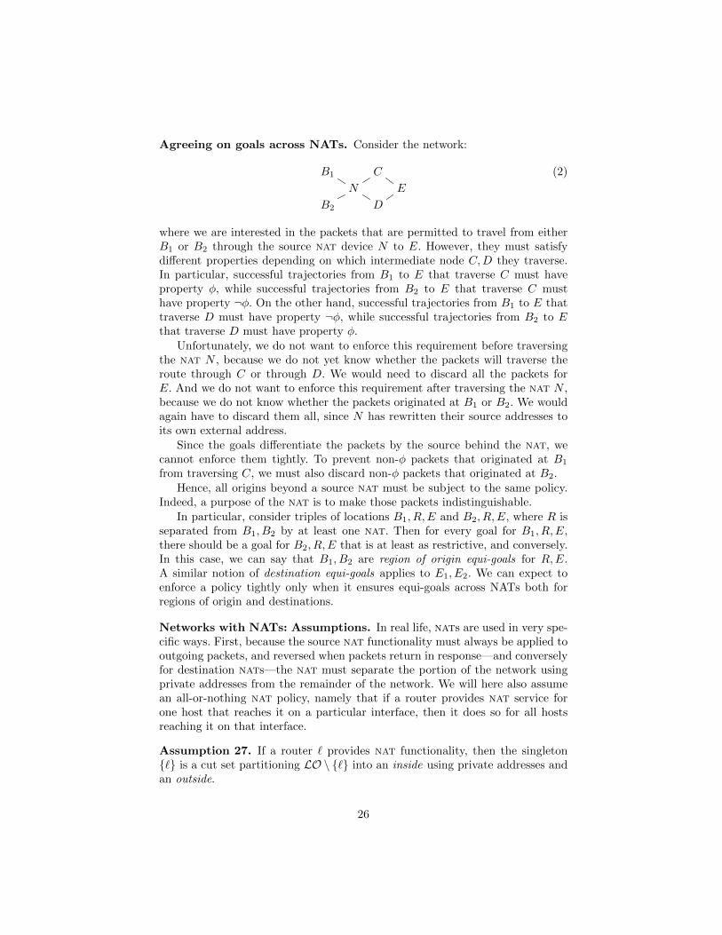
Agreeing on goals across NATs. Consider the network:
B1 C
N E
B2 D
(2)
where we are interested in the packets that are permitted to travel from eitherB1 or B2 through the source nat device N to E. However, they must satisfydifferent properties depending on which intermediate node C,D they traverse.In particular, successful trajectories from B1 to E that traverse C must haveproperty φ, while successful trajectories from B2 to E that traverse C musthave property ¬φ. On the other hand, successful trajectories from B1 to E thattraverse D must have property ¬φ, while successful trajectories from B2 to Ethat traverse D must have property φ.
Unfortunately, we do not want to enforce this requirement before traversingthe nat N , because we do not yet know whether the packets will traverse theroute through C or through D. We would need to discard all the packets forE. And we do not want to enforce this requirement after traversing the nat N ,because we do not know whether the packets originated at B1 or B2. We wouldagain have to discard them all, since N has rewritten their source addresses toits own external address.
Since the goals differentiate the packets by the source behind the nat, wecannot enforce them tightly. To prevent non-φ packets that originated at B1
from traversing C, we must also discard non-φ packets that originated at B2.Hence, all origins beyond a source nat must be subject to the same policy.
Indeed, a purpose of the nat is to make those packets indistinguishable.In particular, consider triples of locations B1, R,E and B2, R,E, where R is
separated from B1, B2 by at least one nat. Then for every goal for B1, R,E,there should be a goal for B2, R,E that is at least as restrictive, and conversely.In this case, we can say that B1, B2 are region of origin equi-goals for R,E.A similar notion of destination equi-goals applies to E1, E2. We can expect toenforce a policy tightly only when it ensures equi-goals across NATs both forregions of origin and destinations.
Networks with NATs: Assumptions. In real life, nats are used in very spe-cific ways. First, because the source nat functionality must always be applied tooutgoing packets, and reversed when packets return in response—and converselyfor destination nats—the nat must separate the portion of the network usingprivate addresses from the remainder of the network. We will here also assumean all-or-nothing nat policy, namely that if a router provides nat service forone host that reaches it on a particular interface, then it does so for all hostsreaching it on that interface.
Assumption 27. If a router ` provides nat functionality, then the singleton{`} is a cut set partitioning LO \ {`} into an inside using private addresses andan outside.
26

nats can be arranged in several layers, so that addresses used outside an “inner”nat may include private addresses served by a subsequent “outer” nat. Nev-ertheless, at any point of the network, the IP addresses that are locally visibleshould be disjoint, in an analogue of Assumption 17:
Assumption 28. Suppose that paths π1, π2 start from B1 and B2 respectively,reaching a shared endpoint R. Then IP(B1) ∩ IP(B2) = ∅ unless B1 = B2 or:
1. πi traverses a nat device properly between Bi and R, where i = 1 or 2; or2. R is a nat device and π1, π2 reach it on different interfaces.
We now can define the equi-goal idea:
Definition 29. A set G of goals has source equi-goals iff, for every nat deviced, if B1, B2 lie on the inside of d and R lies on the outside, then for all goalsψB@B1 → φ@R→ ψE@E, this goal is in G iff ψB@B2 → φ@R→ ψE@E is inG.
G has destination equi-goals iff, for every nat device d, if E1, E2 lie onthe inside of d and R lies on the outside, then for all goals ψB@B → φ@R →ψE@E1, this goal is in G iff ψB@B → φ@R→ ψE@E2 is in G.
G has equi-goals iff both conditions are met. ///
Keep sets with NATs. With nats, packets are no longer unchanged through-out a trajectory. We need to account for these changes, as the packets havedifferent fields at each node, and those fields define if the node keeps or discardsthe packet.
Fix a choice of endpoints B,E. Unlike the nat-free case, we cannot simplymove the preconditions ψB , ψE of a success goal from the beginning and end ofa trajectory to the region R. After all, nat transformations may have alteredthe packet headers between B and R, or R and E. Instead, we will use therelations to keep track of both the state of the packet at the earlier point andthe later point. For this reason, we will now alter the set PrmtB,E(·) to a pair of
relations on packets. Prmt`B,R concerns the “left” half of the trajectory from Bto R; PrmtrR,E concerns the “right” half from R to E. Since B,E are fixed, wedo not indicate them here; we focus on R.
If G is a set of success goals, we will write G(B,R,E) for the subset of Gconcerning B,R,E. If g ∈ G(B,R,E) is a goal ψB@B → φ@R → ψE@E, wewill write PreB(g), Post(g), and PreE(g) for ψB , φ, and ψE , resp.
Prmt`B,R ={(p, q) :
∧g∈G(B,R,E) sa(p) ∈ IP(B) ∧ (PreB(g)(p)
⇒ Post(g)(q))}PrmtrR,E ={(q, p) :
∧g∈G(B,R,E) da(p) ∈ IP(E) ∧ (PreE(g)(p)
⇒ Post(g)(q))}.
Prmt`B,R contains a pair (p0, q0) when p0 satisfies the precondition PreB at thebeginning B, and q0 satisfies the claim Post(g) property at R, meaning that
27
if a packet could follow some path that would transform it from p0 to q0, thenthis would be allowed by the goal statements. Conversely for (q1, p1) ∈ PrmtrR,E ,if q1 could follow some path to E that would transform it to p1, then the goalstatements would allow this. A packet q is worth keeping at a given location ifthere is some real path that leads through R which does transform it in waysthat remain permissible:
Definition 30 (nat-Keep). If ~e = 〈e0, . . . ek〉 is a trajectory, let locs(~e) be thesequence of length k + 2 such that locs(~e)[0] = sender(chan(e0)) and, for all isuch that 1 ≤ i ≤ k + 1, locs(~e)[i] = rcpt(chan(ei−1)).
Trajectory ~e = 〈e0, . . . ek〉 is B,E-worthy iff ~e is a success trajectory, locs(~e)[0] =B, locs(~e)[k + 1] = E, and, for every i where 0 ≤ i ≤ k + 1,
(msg(e0),msg(ei)) ∈ Prmt`B,locs(~e)[i] and
(msg(ei),msg(ek)) ∈ Prmtrlocs(~e)[i],E .
Packet msg(ei) is worth keeping from B to E at R iff for some B,E-worthytrajectory ~e = 〈e0, . . . ek〉, R ∈ locs(~e).
Let KEEPB,E(R) be the set of packets worth keeping from B to E at R. ///
In case there are no nats, then KEEPB,E(R) receives the same meaning aspreviously. By the definition:
Lemma 31. For all q, q ∈ KEEPB,E(R) iff there exist p1, p2 such that (p1, q) ∈Prmt`B,R and (q, p2) ∈ PrmtrR,E. ///
Combining the keep sets for different endpoints. The equi-goal propertyand the IP disjointness assumption (Assumption 28) allow us to combine thekeep sets for different endpoints.
Lemma 32. Suppose that the goals G have the equi-goal property, and that B1 6=B2 but KEEPB1,E(R) ∩ KEEPB2,E(R) 6= ∅. Then
1. There are success trajectories from B1 through R to E or from B2 throughR to E that traverse nats between Bi and R; and
2. If B1, B2 have source equi-goals for R,E, then KEEPB1,E(R) = KEEPB2,E(R).
Suppose that E1 6= E2 but KEEPB,E1(R) ∩ KEEPB,E2
(R) 6= ∅. Then
1. There are success trajectories from B through R to E1 or from B through Rto E2 that traverse nats between R and Ei; and
2. If E1, E2 have destination equi-goals for B,R, then KEEPB,E1(R) = KEEPB,E2
(R).
Proof. By the non-emptiness condition, there is a B1, E-worthy ~e1 and a B2, E-worthy ~e2 both traversing R and with the same packet form p there. If ~e1, ~e2have not yet traversed a nat, then p is in its original form; since these are successtrajectories, this contradicts B1 6= B2. Thus claim 1 holds.
28
Since both trajectories provide p at R, the most recent nats d1, d2 thatrewrote their source addresses both have sa(p) ∈ IP(di). Hence by Assump-tion 28, d1 = d2. Thus we may apply the definition of equi-goals; so the sameconditions occur in the goal statements for B1, B2, and the KEEP sets are thesame. The claims for E1, E2 are symmetric.
That is, equi-goals on nats ensure that KEEP sets are either equal or disjoint.The information in the headers sa(p) and da(p) tells us enough to enforce thegoals G tightly. As before, we define, for a given set of goal statements G:
KEEP∗(`) =⋃B,E
KEEPB,E(`) (3)
We would like now to filter packets as they are passing from one location toanother location at which they should not be kept, i.e., we should discard thecomplement of KEEP∗(`
′) along any edge a : `→ `′. We do this as before:
Definition 33. The acceptance filter af maps arcs to sets of packets, whereaf(a) = KEEP∗(`
′), for each arc a : ` → `′ from ` to `′. We write af(`, `′) foraf(a). ///
We again want to configure our network to discard all packets traversing theedge a that do not belong to the acceptance filter af(a).
Computing the matrices Rchm. We regard source nat operations as oc-curring outbound on an edge e, and as defined by the relation Re(p, p
′). Here,typically, this holds if p has a local source address; p′ has the nat device’s ad-dress as its source address; and p′ agrees with p for destination port and address.The translation for returning packets flowing inbound on the edge is dual.
Suppose now that F (e, d) expresses both the packet rewriting and the filteringthat occurs on edge e in direction d (inbound vs. outbound). In particular, F (e, d)is a relation that holds on a pair of packets (p, q) when p is permitted to passover e in direction d, but is rewritten by the sender to q before transmission. Ifan entry reflects a filter retaining packets satisfying φ without rewriting, thenits entry F (e, d) is the lifted relation ↑ φ, namely the identity relation restrictedto φ. We now construct, for any pair of endpoints B,E:
AF contains these relations AFi,j = F (e, d) in entries i, j, when edge e in direc-
tion d leads from i to j. If there is no edge from i to j, then AFi,j =↑ ∅ is theempty relation.
K is the diagonal matrix where Ki,j =↑ ∅ when i 6= j, and
Ki,i =↑ {q : ∃pB , pE .Prmt`B,i(pB , q) ∧ Prmtri,E(q, pE)}.
Thus, Ki,i contains the pairs (q, q) where q is permitted to pass through i on atrajectory from B to E, for any forms of the packet at the endpoint.
We now use the same matrix operations to compute Rchm for the given F .Each Rchm will contain in position Rchmi,j the relation which contains (qi, qj)
29

iff there is a path from location i to j of length ≤ m such that qi is transformedto qj along that path, and each intermediate qk (for i ≤ k ≤ j) is permitted topass through location k on a trajectory from B to E.
Rch0 = K, since paths of length 0 lead only from i to i, and Ki,i reflects thepackets permitted there.
Rch1 = K + (KAF K). A path of length ≤ 1 is either empty or else it takes onestep from i to an adjacent location j.F determines whether a packet can traverse this edge and how it is rewrit-ten. The multiplication by K on the left restricts the results to the packetsthat could permissibly be present at i before traversing the edge, while themultiplication by K on the right restricts them to packets permissibly at jafter the step.
Rch(2m) = (Rchm Rchm), since the paths of length ≤ 2m are just the paths thatdivide into two paths of length ≤ m, respectively ending and beginning atthe same node k.
Rch = Rchb is the fixed point of Rchm.
When the only packet transformations are nats, this recursion will again reachits fixed point Rch after O(log2 |LO|) matrix multiplications. Although non-simple paths can bring transformed packets back to nats they have alreadytraversed, nat outputs are essentially idempotent: They simply select fixed ad-dresses and (for source nats) new undistinguished ports. Thus, these packetswill not lead to a larger set of output, nat-transformed results. Packet trans-formations could be conceived that would converge to a fixed point only afterlarge numbers of multiplications, possibly of the order of the number of distinctpackets. However, non-simple paths do not delay the fixed point for nats.
Lemma 34. KEEP(i) = {q : ∃pb, pE . (pB , q) ∈ RchB,i ∧ (q, pE) ∈ Rchi,E}.
Security and Success Functionality. We justify security for this filteringposture much as before, but using the equi-goals properties. For given endpointsB,E, the matrix Rchm summarizes what permissible trajectories of length ≤ mcan deliver from B and to E. When we define KEEP∗(`) as the union of thesets KEEPB,E(`), we rely on Lemma 32 to justify that this does not erase thedifferences between KEEP sets for the different endpoints.
As for its maximality, we observe as before that we filter out only packetsthat have no permissible success trajectories.
Firewall Configuration. As in the plain case, we define the firewall behaviourFW based on the KEEP∗ sets and the function F (e, d). Consider the subgraph
· ci→ `co→ `′ where ` and `′ may have nat behavior defined by the function F used
to define AF . Then FW(t, ci, co, p) =
{qo ∈ KEEP∗(`′) : ∃qi ∈ KEEP∗(`) .
(p, qi) ∈ F (ci, in) ∧(qi, qo) ∈ F (co, out)}.
30
That is, ` may queue qo for delivery over co if there is a qi into which it cantranslate p along channel ci, and qi is a packet it can keep, and it can translateqi into qo outbound on co, and moreover `′ can keep qo. The router ` must dofiltering on both sides, because `′ may be a network region or end host, or arouter without filtering functionality.
As with Thm. 23 and 20:
Theorem 35. Let G be a non-empty collection of success goals, and let theframe F obey FW and have every channel connected to at least one router. Fenforces G. If F ′ (with the same graph and nat behaviour) enforces G, then Fis as successful functionally as F ′. ///
The complexity of generating filters using this method depends on several consid-erations. One is the complexity of the underlying ring operations set intersectionand relative product. Although these are potentially computationally hard, theyappear to be easy in practice. In particular, operations relevant to network fil-tering rarely mix many different bits. For instance, the low order bit of a sourceaddress will probably never be combined with the third bit of a destination port.
The complexity also depends on the number of locations in the network.While this would seem large, in fact, we do not need to represent every networkdevice as a separate location. Only the ones that are relevant to the securitypolicy—by requiring some distinctive protection—or to the security processing—by being a location at which we will filter or route—need to be represented. Theremaining devices may be coalesced with their neighbors, and represented by asingle location. This abstraction leads to fairly small graphs.
If we regard a ring operation as a unit of computational effort, and let k bethe number of locations in the abstracted graph, then each matrix multiplicationis below O(k3), and computing Rch requires log2 k multiplications. This mustbe done k2 times, performing the computations for KEEPB,E(·) as B,E vary.Thus, the full computation is O(k5 log k).
7 Conclusion
This paper develops specifications for security goals governing how packets tra-verse the network, and shows how to distribute filtering functionality to differentnodes. We have proved that the resulting filtering implements the security con-straints while providing maximal service functionality. We have moreover imple-mented and validated our results using a tool that automatically localizes thefilters and generates configurations for all the firewalls in the network.
As a future work, from a theoretical point of view we plan to give an en-forcement of the spoofing goals (that consider only trajectories with spoofingat creation), and promiscuous delivery goals (i.e., trajectories with promiscuousdelivery). From a practical point of view we plan to extend Mignis to localizefilters also when nats are present.
Acknowledgements This work was partially supported by FCT projects Con-fident PTDC/EEI-CTP/4503/2014 and FCT project UID/EEA/50008/2013.
31
References
1. P. Adao, C. Bozzato, R. Focardi G. Dei Rossi, and F.L. Luccio. Mignis: A semanticbased tool for firewall configuration. In IEEE 27th Computer Security FoundationsSymposium (CSF 2014), Vienna, Austria, pages 351–365. IEEE CS Press, July2014.
2. E. Al-Shaer, A. El-Atawy, and T. Samak. Automated Pseudo-Live Testing ofFirewall Configuration Enforcement. IEEE Journal on selected areas in communi-cation, 27(3):302–314, 2009.
3. C. J. Anderson, N. Foster, A. Guha, J.-B. Jeannin, D. Kozen, C. Schlesinger, andD. Walker. NetKAT: Semantic foundations for networks. In Proc. of the 41st ACMSIGPLAN-SIGACT Symposium on Principles of Programming Languages (POPL2014). ACM, 2014.
4. Randal E. Bryant. Graph-based algorithms for boolean function manipulation.IEEE Trans. Comput., 35(8):677–691, August 1986.
5. Frenetic, a family of network programming languages. http://www.
frenetic-lang.org/, 2013.6. J.D. Guttman and A.L. Herzog. Rigorous automated network security manage-
ment. International Journal for Information Security, 5(1–2):29–48, 2005.7. J.D Guttman and P.D. Rowe. A cut principle for information flow. In IEEE 28th
Computer Security Foundations Symposium (CSF 2015), Verona, Italy, pages 107–121. IEEE CS Press, July 2015.
8. Ahmed Khurshid, Wenxuan Zhou, Matthew Caesar, and PB Godfrey. Veriflow:verifying network-wide invariants in real time. ACM SIGCOMM Computer Com-munication Review, 42(4):467–472, 2012.
9. T. Nelson, C. Barratt, D.J. Dougherty, K. Fisler, and S. Krishnamurthi. The mar-grave tool for firewall analysis. In Proceedings of the 24th International Conferenceon Large Installation System Administration (LISA’10), pages 1–8, Berkeley, CA,USA, 2010. USENIX Association.
10. J. Walsh. Icsa labs firewall testing: An in depth analysis. http://bandwidthco.
com/whitepapers/netforensics/penetration/Firewall\%20Testing.pdf, 2004.11. B. Zhang, E. Al-Shaer, R. Jagadeesan, J. Riely, and C. Pitcher. Specifications of
a high-level conflict-free firewall policy language for multi-domain networks. InProc. of ACM Symposium on Access Control Models and Technologies (SACMAT2007). ACM, 2007.
Appendix
Table II reports the output of the localization tool that automatically generatedthe Mignis+ configuration for the four firewalls.
32

FIREWALL fw1
Sensitive@if_Sensitive : 22 > Trusted@if_fw2 | -m state --state ESTABLISHED,RELATEDSensitive@if_Sensitive > Internet@if_fw2 : 443
Sensitive@if_Sensitive > Internet@if_fw3 : 443
Trusted@if_fw2 > Sensitive@if_Sensitive : 22Internet@if_fw2 : 443 > Sensitive@if_Sensitive | -m state --state ESTABLISHED,RELATED
Untrusted@if_fw2 > Internet@if_fw3 : 80Trusted@if_fw2 > Internet@if_fw3
Internet@if_fw3 : 443 > Sensitive@if_Sensitive | -m state --state ESTABLISHED,RELATED
Internet@if_fw3 : 80 > Untrusted@if_fw2 | -m state --state ESTABLISHED,RELATEDInternet@if_fw3 > Trusted@if_fw2 : 22Internet@if_fw3 > Trusted@if_fw2 | -m state --state ESTABLISHED,RELATED
FIREWALL fw2
Trusted@if_Trusted > Sensitive@if_fw1 : 22Trusted@if_Trusted > Internet@if_fw1
Trusted@if_Trusted > Internet@if_fw4
Untrusted@if_Untrusted > Internet@if_fw1 : 80
Sensitive@if_fw1 : 22 > Trusted@if_Trusted | -m state --state ESTABLISHED,RELATEDInternet@if_fw1 > Trusted@if_Trusted : 22Internet@if_fw1 > Trusted@if_Trusted | -m state --state ESTABLISHED,RELATED
Internet@if_fw1 : 80 > Untrusted@if_Untrusted | -m state --state ESTABLISHED,RELATED
Sensitive@if_fw1 > Internet@if_fw4 : 443
Internet@if_fw4 > Trusted@if_Trusted : 22Internet@if_fw4 > Trusted@if_Trusted | -m state --state ESTABLISHED,RELATED
Internet@if_fw4 : 443 > Sensitive@if_fw1 | -m state --state ESTABLISHED,RELATED
FIREWALL fw3
Internet@if_Internet : 443 > Sensitive@if_fw1 | -m state --state ESTABLISHED,RELATEDInternet@if_Internet : 80 > Untrusted@if_fw1 | -m state --state ESTABLISHED,RELATEDInternet@if_Internet > Trusted@if_fw1 : 22Internet@if_Internet > Trusted@if_fw1 | -m state --state ESTABLISHED,RELATED
Sensitive@if_fw1 > Internet@if_Internet : 443Untrusted@if_fw1 > Internet@if_Internet : 80
Trusted@if_fw1 > Internet@if_Internet
FIREWALL fw4
Internet@if_Internet : 443 > Sensitive@if_fw2 | -m state --state ESTABLISHED,RELATEDInternet@if_Internet > Trusted@if_fw2 : 22Internet@if_Internet > Trusted@if_fw2 | -m state --state ESTABLISHED,RELATED
Sensitive@if_fw2 > Internet@if_Internet : 443Trusted@if_fw2 > Internet@if_Internet
Table 3. Mignis+ rules automatically generated for the four firewalls of the examplenetwork.
33