locate: low-cost asteroid topographical explorer mission
TRANSCRIPT

LoCATE: Low-Cost Asteroid Topographical Explorer
Mission Proposal
By
Matthew Ciasto, Joseph Lasser, Catherine McCarthy, Joseph Mueller, Jeffrey
Pekosh, and Seth Zelman
Faculty Advisor: Zachary Putnam
May 15, 2016

1
LoCATE Team
Matt Ciasto Team Leader
AIAA Member Number: 688750
Joseph Lasser Communications and ADACS Lead
AIAA Member Number: 688751
Caite McCarthy Structures and Thermal Lead
AIAA Member Number: 500517
_______________________
_______________________
_______________________
Joseph Mueller Budget and Costing Lead
AIAA Member Number: 688737
Jeffrey Pekosh Trajectory and Propulsion Lead
AIAA Member Number: 582465
Seth Zelman Science and Power Lead
AIAA Member Number: 688740
_______________________
_______________________
_______________________

2
Executive Summary
The Low-Cost Asteroid Topographical Explorer (LoCATE) is a precursor mission for future human
spaceflight missions to Near Earth Asteroids (NEA). The primary objectives of the LoCATE mission are
to (1) evaluate the candidacy of a target asteroid as a potential destination for human exploration, (2)
minimize risks for future human missions, and (3) demonstrate low cost and low risk mission architecture.
LoCATE will accomplish these objectives by conducting scientific investigations that contribute to a better
understanding of the target asteroid and its environment. The proposed mission design utilizes proven
technologies to accomplish mission objectives at low risk and a total lifecycle cost of under $100M.1-2 The
completed design for the LoCATE spacecraft is shown below in Figure 1 with the solar panels deployed
Figure 1. Image of the LoCATE spacecraft.
The primary science goal for the LoCATE mission is to model a target asteroid and its surrounding
environment. An accurate model of the target asteroid will provide critical information for the selection of
future human exploration destinations. This data will also contribute to minimizing the risks associated with
future missions. A robotic spacecraft will station-keep at the target asteroid and conduct multiple scientific

3
investigations that contribute to developing this model. The primary science investigations include high-
resolution optical and spectral imaging of the target asteroid surface. Optical imaging will be accomplished
using a multispectral imager aboard the spacecraft. Data collected by the imager will allow the LoCATE
science team to build a detailed topographical map of the asteroid surface. Spectral imaging will be
conducted by an onboard Visual and Infrared (VIR) spectrometer. Spectral data from the asteroid surface
will contribute to identifying and mapping the mineralogical composition.
Additional science investigations include monitoring the effect of gravitational perturbations on the
LoCATE spacecraft. These perturbations indicate concentrations of mass within the asteroid and help
derive the mass density, which can provide insight on asteroid composition and history. Gravitational
perturbation investigations require no additional instrumentation, yet they provide valuable information
about the asteroid. Another scientific investigation for the LoCATE mission is to collect data on the
radiation environment in interplanetary space and near the asteroid. To ensure a potential crew’s safety, it
is necessary to have an understanding of potential radiation threats to any future mission. This investigation
uses a dosimeter onboard the spacecraft to measure radiation levels throughout the LoCATE mission.
Radiation dosage information collected during the mission will provide valuable data to supplement current
knowledge about the radiation environment of the solar system. This information can ultimately be used to
plan future human and robotic missions.
The final scientific investigation is to use a magnetometer to identify any magnetic properties of
the target asteroid. Similar to the radiation investigation, the magnetometer will take measurements both
before and after asteroid rendezvous. Any increase in magnetic field strength will likely indicate a
significant metallic presence in the asteroid. This would help classify the asteroid and aid in evaluating the
value of a future manned exploration mission. Combined, these science investigations work together to
develop a thorough and accurate model of the asteroid and its environment at minimal risk and minimal
cost.
Utilizing trajectory calculating software such as STK and EMTG, orbit trajectories for over 80
candidate asteroids were explored, which were found through the Near-Earth Object Human Space Flight

4
Accessible Targets Study (NHATS) database. This list was shortened to four final candidate asteroids based
on the viability of each asteroid target as well as its ability to fulfill the aforementioned mission
requirements. The asteroid candidate with the highest mission feasibility was determined to be asteroid
2000 SG344. This asteroid was selected in part due to its low ΔV, but also for its low transit time
requirement and its suitability for a human mission in the late 2020s. The selection of an asteroid required
that it will be a viable target beyond the scope of this mission, and would still be a feasible option for human
exploration until at least 2025, which 2000 SG344 met due to the ideal departure year of 2028.
This asteroid will act as a Phase A baseline target for mission design. It was determined that the
most feasible launch option for the LoCATE mission will be to utilize a secondary payload opportunity.
This is largely due to the mission cost cap of $100M. The launch provider will place the LoCATE spacecraft
into a geostationary transfer orbit (GTO), where the spacecraft will perform systems checkout and
diagnostics. Assuming all systems are performing nominally, the spacecraft will initiate a solid booster
stage to reach Earth escape. Following escape, the spacecraft will undergo a 650-day low thrust transfer to
2000 SG344.
LoCATE contains an attitude determination and control subsystem (ADACS) that will be
responsible for pointing both the payloads’ sensors and the antennas towards their appropriate targets. The
subsystem contains six sun sensors and a star tracker module to assist the spacecraft in achieving its pointing
requirement. In addition to these instruments, there are 12 thrusters that make up the control segment for
the ADACS.
LoCATE will primarily use the Deep Space Network (DSN) for ground communications, but the
DSN cannot be utilized while LoCATE is in GTO. During that time, the Near Earth Network (NEN)
infrastructure will be primarily utilized for communications. Communications onboard the satellite will
consist of a medium gain horn antenna for deep space communication in addition to two dual-frequency
patch antennas. The purpose of the patch antenna is to provide a backup system in case of fault, and to act
as the communication interface for the NEN. An X-band transmitter was selected due to its size and
5
reliability. Finally, a Small Deep Space Transponder is included in the communications infrastructure,
which will receive uplinked data and send a beacon signal for spacecraft health information.
The main spacecraft computer will control command and data handling (C&DH). The computer
will maintain smooth operation between subsystems by acting as the computational center of any subsystem
that does not have its own allocated processor. Each subsystem will transmit information back to the main
computer, which will then be relayed to the operators on Earth to give an accurate depiction of the current
state of the spacecraft. The C&DH subsystem also stores all science data and performs signal modulation
and decoding.
There are two components to the LoCATE propulsion system. The first is a solid rocket motor that
will generate the required ΔV for Earth escape. The solid rocket motor will be a STAR 15G manufactured
by Orbital ATK. This booster will be activated at the perigee of the checkout orbit, and was selected due to
its lower mass and cost than a liquid monopropellant or bipropellant propulsion system. After the activation
and exhaustion of the booster, it will be jettisoned from the main bus. Following booster stage separation,
the spacecraft will utilize 3 BIT-7 ion thrusters to complete the low thrust transit to the target asteroid.
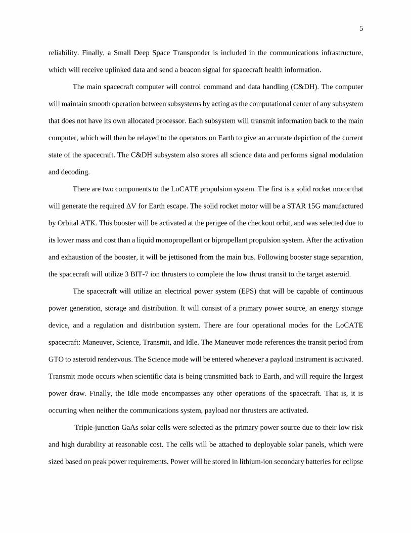
The spacecraft will utilize an electrical power system (EPS) that will be capable of continuous
power generation, storage and distribution. It will consist of a primary power source, an energy storage
device, and a regulation and distribution system. There are four operational modes for the LoCATE
spacecraft: Maneuver, Science, Transmit, and Idle. The Maneuver mode references the transit period from
GTO to asteroid rendezvous. The Science mode will be entered whenever a payload instrument is activated.
Transmit mode occurs when scientific data is being transmitted back to Earth, and will require the largest
power draw. Finally, the Idle mode encompasses any other operations of the spacecraft. That is, it is
occurring when neither the communications system, payload nor thrusters are activated.
Triple-junction GaAs solar cells were selected as the primary power source due to their low risk
and high durability at reasonable cost. The cells will be attached to deployable solar panels, which were
sized based on peak power requirements. Power will be stored in lithium-ion secondary batteries for eclipse

6
periods. A power processing unit will control power regulation and distribution, as well as monitor system
health and control solar panel orientation.
The spacecraft will be made up of two modules. The main bus will be box-shaped aluminum alloy
casing that houses all internal components and provides integration points for all external components. The
BIT-7 thrusters, attitude determination and control (ADACS) thrusters, antennae, and external deployable
solar panels will all be located on the exterior of bus module. The optical camera and spectrometer will be
located within the bus, but will have visibility to the outside environment when the respective lens covers
are open. The additional instrumentation, main spacecraft computer, power storage system, and all wiring
will also be housed within the main bus. The second module consists of the STAR 15G solid motor stage,
and will be detached following Earth escape. The spacecraft configuration at launch will satisfy the
125x100x100 cm volumetric constraint laid out by the secondary payload provider.
Both active and passive thermal control systems are implemented by the LoCATE spacecraft. The
two main components of the Passive Thermal Control System (PTCS) are the spacecraft surface coating
and Multilayer Insulation (MLI). The spacecraft surface will be finished with polished aluminum to insulate
the spacecraft from solar radiation. Polished aluminum was selected due to its lightweight and low-cost
properties. MLI blankets made from Mylar sheets with aluminum finish will also cover the spacecraft and
serve as additional protection from thermal radiation. The Active Thermal Control System (ATCS) will
include thermal radiators, cold plates and patch heaters for the instruments within the payload. The
temperature inside the spacecraft will be measured using temperature sensors. An external radiator will be
utilized to reject excess heat created by the instruments. Cold plates will assist in overheating of the
instruments, while patch heaters will ensure that all components stay within safe temperature ranges.
The Assembly, Test and Launch Operations (ATLO) will be similar to previous missions analogous
to the LoCATE mission. After the components have been delivered by their respective suppliers, they will
be handled and integrated in a clean room by a group of skilled technicians. Before and after integration,
each instrument will be tested to ensure full functionality. From there, the spacecraft will undergo
environmental testing. This includes vibration testing, thermal cycling, and vacuum testing. After complete

7
systems testing, the spacecraft will be transported to the launch site for integration with the launch vehicle.
The spacecraft will undergo propellant testing prior to integration with the launch vehicle.
The LoCATE mission utilizes simple, proven technologies to minimize risks and costs. Only
heritage components with high Technology Readiness Levels (TRL) are utilized by the spacecraft. No
technology development is required for the LoCATE mission, ensuring affordable scalability for any future
missions.
In order to streamline decision making and ensure development is completed as efficiently as
possible, a hierarchal management approach has been established. This system ensures that design decisions
are made at the appropriate level. The Principal Investigator (PI) is the final decision-making authority and
is responsible for mission success. The PI oversees a science team and the Program Manager (PM). The
PM manages project engineers and project managers, who each manage team leaders. All design change
requests will be evaluated by team leaders to determine necessity and feasibility of each change.
Roles and responsibilities are explicitly defined in order to maximize productivity and boost
accountability. A lead engineer for each subsystem will be assigned, and each be appointed a team of
engineering personnel. Project engineers will monitor the requirements of the mission and ensure they are
in focus throughout development. They will evaluate risk and reliability and report results to the PM. All
testing and integration will be done by a team of test engineers. These engineers will be responsible for
developing and conducting tests on all spacecraft components, purchased equipment, and the fully
assembled spacecraft. A production engineer will manage a team of technicians responsible for spacecraft
assembly and integration.
Formal reviews will be conducted throughout the project development to evaluate progress,
budgeting, and risk management. These reviews will bring the PI and PM together for formal presentations
of design progress by team leaders. A conclusive “red team” review is scheduled 12 months prior to launch
integration in order to conclude evaluations of all project risks and implemented risk mitigation strategies.
The LoCATE mission operations team will vary based on mission phase. A smaller team will
handle prelaunch operations and will increase in size following launch. A smaller, cross-trained staff will

8
be employed due to the low complexity and size requirements of the mission. Overall, the LoCATE mission
will follow closely in operations to NASA’s NEAR Shoemaker mission, with some adjustments to
accommodate for the differences between the two missions. Science data will flow from LoCATE through
the DSN to the mission operations center. From there, data is transferred to the science data center for
archiving and distribution. Furthermore, orbit determination and maneuver planning with be passed from
the mission design and navigation center to the mission operations center. Completing the circuit, the
mission operations center shall relay spacecraft commands to the DSN for spacecraft communications back
to LoCATE.
Current scheduling places spacecraft launch in the first quarter of 2022. This occurs well before the
launch deadline of 2028. A detailed mission schedule explicitly outlines mission phases, chief project
reviews, and schedule reserves. The critical path is determined by the spacecraft bus development. Due to
high TRL, the booster stage and science instrument development and integration are not schedule critical.
The final launch date will be determined by the launch provider. Additionally, the launch vehicle provider
offers a detailed timeline of chief deliverables between the launch provider and the secondary payload
provider.
Both implementation and mission risks will be mitigated throughout mission planning. The mission
cost stands at $90M with a 11% reserve. Additionally, LoCATE project development began with a 35%
mass reserve to ensure that spacecraft mass does not exceed secondary payload constraints. Finally, since
asteroid target evaluations were still under examination throughout early pre-phase A, a ΔV margin of 20%
was established to allow for corrections and errors in the trajectory. The spacecraft also can load sufficient
extra propellant into its propulsion tanks to allow for flexibility in target selection without negatively
affecting the schedule or budget.
Utilizing a qualitative risk assessment, top mission risks were evaluated. These operational risks
include major events such as establishing an uplink and downloading data with the medium-gain antenna.
To mitigate this risk, the link budget has been given an appropriate 5 dB link margin, and LoCATE will be
utilizing the DSN, which is a proven technology. Another risk is that the launch will be delayed by the

9
launch provider. Schedule and cost reserves have been added to the mission to accommodate this potential
risk. To resolve the potential for station-keeping propellant to be prematurely exhausted, there is a 30%
propellant margin for the station-keeping phase, in addition to extensive ground simulation to prove the
trajectory outlined will be successful. The final operational risk is that the electronics or instrument will
fault during the mission, either due to launch or booster vibrations, or by an anomaly electronic failure.
LoCATE utilizes redundancy with its subsystems to provide reliability at low mass and low cost, and only
proven components will be utilized in spaceflight. Thus, the likelihood of this risk occurring is low.
The $100M cost cap provides a strict design space for the LoCATE mission. In order to maximize
scientific return while minimizing complexity and risk, a detailed cost model was created to capture every
work breakdown statement (WBS) element throughout the mission lifecycle. The cost model combines
analogous and parametric cost models. Historical data in analogous models provides context for mission
size and costing while parametric models that utilize cost estimating relationships (CERs) produce detailed
and vigorous cost estimates. The combination of these models ensures an accurate cost model for the
LoCATE mission. The total cost remains under the $100M cost cap with 11% reserve.
LoCATE is a multi-faceted mission that achieves a multitude of goals in a low-cost, high reliability
mission model. The aforementioned subsystems work together to complete the mission goals. These goals
include: (1) evaluate the candidacy of a target asteroid as a potential destination for human exploration, (2)
minimize risks for future human missions, and (3) demonstrate low cost and low risk mission architecture.
Additionally, all of the subsystem requirements are met. Finally, the overall RFP requirements are fulfilled.
Consequently, LoCATE elevates the standard of small satellite architecture by encompassing a variety of
scientific objectives to improve the feasibility of human exploration.

10
Table of Contents
A LoCATE Fact Sheet ........................................................................................................................... 12 B Proposed Science Investigations and Instrumentation ....................................................................... 13
B.1 Science Overview ....................................................................................................................... 13 B.2 Science Objectives ...................................................................................................................... 13
B.2.1 Surface Topographical Imaging .......................................................................................... 14 B.2.2 Visual and Infrared Spectroscopy ....................................................................................... 15 B.2.3 Gravity Perturbations .......................................................................................................... 16 B.2.4 Radiation Environment ....................................................................................................... 17 B.2.5 Magnetic Properties ............................................................................................................ 17
B.3 Instrumentation ........................................................................................................................... 18 B.3.1 Multispectral Imager ........................................................................................................... 19 B.3.2 VIR Spectrometer ............................................................................................................... 20 B.3.3 Dosimeter ............................................................................................................................ 20 B.3.4 Magnetometer ..................................................................................................................... 21
B.4 Science Traceability Matrix ........................................................................................................ 22 B.5 Data Acquisition ......................................................................................................................... 23 B.6 Data Analysis and Archive ......................................................................................................... 24
C Mission Implementation ..................................................................................................................... 26 C.1 Mission Implementation Overview ............................................................................................. 26
C.1.1 Compliance Matrix ............................................................................................................. 26 C.1.2 Requirements List ............................................................................................................... 27 C.1.3 Concept of Operations ........................................................................................................ 29 C.1.4 Spacecraft Diagram ............................................................................................................. 30 C.1.5 Mass Budget ........................................................................................................................ 31 C.1.6 Power Modes ...................................................................................................................... 32
C.2 Trajectory Design ........................................................................................................................ 33 C.2.1 Mission Trajectory .............................................................................................................. 33 C.2.2 Candidate Asteroids ............................................................................................................ 35 C.2.3 Trajectory Optimization ...................................................................................................... 39 C.2.4 Launch Vehicle Analysis .................................................................................................... 43
C.3 Spacecraft Subsystems ................................................................................................................ 44 C.3.1 Attitude Determination and Control.................................................................................... 44 C.3.2 Command and Data Handling (C&DH) .............................................................................. 47 C.3.3 Communications ................................................................................................................. 49 C.3.4 Propulsion ........................................................................................................................... 60 C.3.5 Power .................................................................................................................................. 64 C.3.6 Structures ............................................................................................................................ 70 C.3.7 Thermal Control .................................................................................................................. 73
C.4 Assembly, Test, and Launch Operations (ATLO) ...................................................................... 75 C.5 Technology Development ........................................................................................................... 77 C.6 Management and Schedule ......................................................................................................... 78
C.6.1 Management Approach, Organization, Decision Making Process ..................................... 78 C.6.2 Operations ........................................................................................................................... 79 C.6.3 Project Schedule .................................................................................................................. 80
C.7 Anticipated Risks and Mitigation Strategies ............................................................................... 83 C.7.1 Top Mission Risks .............................................................................................................. 83
C.8 Cost and Cost Estimating Methodology ..................................................................................... 85 C.8.1 Cost Summary ..................................................................................................................... 85

11
C.8.2 Cost Estimating Methodology ............................................................................................ 86 C.8.3 Validity of Cost Estimates .................................................................................................. 91
D References .......................................................................................................................................... 93 E Proposal Acronyms/Abbreviations..................................................................................................... 95

12
Obtain high resolution images of target
asteroid to generate topographical map of
surface
Obtain high resolution spectral data in
visible and infrared spectral ranges to map
mineralogical composition
Measure asteroid gravitational field to
estimate mass distribution
Measure radiation environment throughout
LoCATE mission
Measure magnetic field near asteroid to
detect magnetic properties
A LoCATE Fact Sheet
Mission Architecture
Multispectral Imager
9.3 m/pixel at 100 km orbit, 150 mm focal
length, 5.5° x 5.5° FOV
Visual and Infrared Spectrometer
25 m/pixel at 100 km, 0.25-5.0 µm range
3-axis Fluxgate Magnetometer
±60 µT range, ±10 nT sensitivity, 10 Hz
bandwidth
Micro Dosimeter
40 krad range, ±14 µrad sensitivity
Nominal Launch Date: 1/1/2022
Notional Target: 2000 SG344
Launch Orbit: GTO
Trajectory: Booster stage out of GTO then
transfer to electric propulsion
Booster ΔV: 864 m/s
Ion Thruster ΔV: 3999 m/s
Dry Mass: 155 kg
Launch Mass: 293 kg
Peak Power: 1014.5 W
Power Source: Triple-junction GaAs solar
cells
Data Transfer: Med-Gain Horn
Science Goals Management Approach
Science Payload
Cost Summary
Schedule
Element Risk Mitigation Strategy
Spacecraft
System
Design
Cost
11% cost reserve for low
risk mission, heritage
technology minimizes cost
from tech. development and
testing
Launch
Vehicle
Launch
Delay
Schedule and cost reserve to
support 30 day delay
Mission
Design
Station-
keeping
30% station-keeping ΔV
margin, extensive simulation
Launch Cost $10.0 M
Science Cost $10.2 M
Program Level Cost $8.5 M
Total Cost $90.2 M
Mission Reserve 11%
An explicit hierarchical management approach
establishes clear chain of command to streamline
decision making. System development
responsibilities have been definitively assigned to
boost productivity and accountability.

13
B Proposed Science Investigations and Instrumentation
B.1 Science Overview
Since 1972, human spaceflight has been limited to Low-Earth Orbit (LEO). With space exploration
now a global enterprise, humans are starting to look beyond LEO to further destinations. There are many
options for exploring the solar system and NASA has identified Mars as a challenging, yet feasible, goal.
In preparation for a future crewed mission to Mars, NASA plans to test technological capabilities by
exploring closer destinations.4 An example of this, the proposed Asteroid Redirect Mission (ARM), is set
to take place in the 2020s and will “robotically capture and redirect a small NEA or a multi-ton boulder
from the surface of a larger NEA to a stable orbit around the moon, where astronauts will visit and gather
samples”.5 A manned mission to a NEA would significantly contribute to lowering the risk of a mission to
Mars. A robotic precursor mission to a NEA would present a low cost, reliable option for gathering
information that could help identify candidate asteroids. The primary objectives of the LoCATE mission
are derived from the need for valuable scientific data to prepare humans for future exploration of a NEA.
The LoCATE mission objectives are threefold: (1) Evaluate the candidacy of a target asteroid as a
potential destination for human exploration, (2) Minimize risk for future human missions, and (3)
Demonstrate low cost and low risk mission architecture. These objectives are attainable given the mission
constraints and each provide valuable information for the future of human space exploration. LoCATE
mission success is defined by the completion of these objectives. By utilizing a robotic spacecraft capable
of station-keeping at a chosen target asteroid, on-board instruments will conduct scientific investigations
that contribute to meeting the mission objectives.
B.2 Science Objectives
As a precursor mission for future NEA human exploration missions, the primary science goal for
the LoCATE mission is to model the environment of an asteroid. By successfully modeling the target
asteroid and its surrounding environment, the three main mission objectives will be met. Science data
collected by the LoCATE spacecraft will contribute to either eliminating the asteroid as a future target, or

14
will assist in preparing humans for safe and successful exploration of the asteroid. LoCATE will conduct
scientific investigations that each provide unique insight into the asteroid environment and improve
understanding of the target asteroid’s surface topography, mineralogy, gravitational field, and radiation and
magnetic environment. Each science investigation was evaluated based on cost, reliability, and value of
scientific impact. The $100M cost cap limits the quantity of scientific investigations. Therefore, it is crucial
that each experiment yields a valuable set of information applicable to eventual human exploration.
Based on the value of their individual contributions to completing the overall mission objectives,
the primary investigations include high-resolution optical imaging for topographical mapping and visual
and infrared spectrometry to identify the mineralogical composition. These primary investigations work
together to provide high-resolution images of the asteroid surface across a broad spectral range. Additional
investigations, such as gravity mapping, radiation sensing, and magnetic field sensing, were identified as
relatively inexpensive and highly reliable and therefore also included in the mission design. Given the
$100M cost limit, this set of investigations provides the most valuable data for classifying and modeling
the asteroid. The LoCATE science goals, required instrumentation, and scientific impact is summarized in
the Science Traceability Matrix in section B.4. Successful completion of each investigation demonstrates
the capabilities of the proposed low cost and low risk mission architecture.
B.2.1 Surface Topographical Imaging
Human exploration of any extraterrestrial object requires extensive prior knowledge about the
target. Arguably, the most important piece of precursor information is surface imaging and topography.
NASA has discovered roughly 14,000 NEAs, yet very few asteroids have been examined thoroughly
enough to develop the high resolution surface imaging necessary for human exploration.6 Mission design
engineers can use knowledge of the target surface to (1) determine whether or not exploration of the target
is at all feasible, (2) if exploration is possible, determine if the target is a worthwhile destination, and (3) if
the target is worth visiting, minimize risks to future missions. Consequently, the goal of this investigation
is to generate high resolution surface imaging at multiple altitudes.

15
The images collected by LoCATE will provide sufficient information about the target asteroid to
allow it to be considered for future exploration. Wide field of view images will determine the global asteroid
shape and volume. High resolution color images will contribute to modelling the surface topography and
geomorphology of the asteroid. This detailed model can be used to identify interesting surface features that
could improve the asteroid’s candidacy as a destination for humans. Additionally, the images will assist in
identifying possible landing sites or hazards for exploration vehicles. By observing the surface images over
time, the asteroid spin state can be estimated, which further contributes to developing a model of the
asteroid. Knowledge of the asteroid spin state is also valuable for the design of future human exploration
missions. For example, an erratically spinning asteroid would pose significant challenges for a landing
vehicle.
This investigation has significant impact to the overall mission objectives of determining feasibility
of asteroid exploration and minimizing risk associated with future missions. Additionally, the data provided
by this investigation helps to identify the origin and evolution of the asteroid, which contributes to a better
understanding of the origins of the entire solar system.
An onboard framing camera capable of multispectral imaging will be integrated onto the spacecraft.
When the spacecraft arrives at the target asteroid, the camera will activate, open the lens protector, and
record images during the course of the science orbit. This will allow LoCATE to capture wide field of view
images of the entire asteroid, as well as high resolution images of the surface for topographical mapping
and geomorphological observations.
B.2.2 Visual and Infrared Spectroscopy
The Small Main-Belt Asteroid Spectroscopic Survey (SMASS) is a taxonomic system that
classifies asteroids based on spectral properties, color, and albedo. By observing asteroids across a range
of wavelengths from the visible and infrared spectrums, SMASS differentiates asteroids into three main
categories: carbonaceous (C-type), silicaceous (S-type), and metallic (X-type).7 An understanding of the
asteroid mineralogical properties provides clues to the asteroid history and is a key consideration for the

16
selection of future human exploration targets. Therefore, to further model the target asteroid, the LoCATE
spacecraft will identify the spectral characteristics of the surface to classify the mineralogical properties.
Data from a spectrometer capable of resolving wavelengths in the visible and infrared spectral
ranges will elucidate the mineralogical composition of the asteroid surface. Every mineral reflects light at
a particular wavelength, and these minerals can be identified by measuring the spectral absorption of the
reflected light. The results of this visual and infrared spectroscopic experiment can lead to the valuable
discovery of minerals such as silicates, metals, oxides, salts, or ices.8 This information is critical to
evaluating the asteroid as a candidate for further exploration as it can help design future investigations.
Additionally, this investigation will allow the LoCATE science team to map the spatial distribution of
various mineralogical types, allowing the crew of any future manned mission to be prepared for sample
collection.9 Lastly, data from this investigation will help scientists draw conclusions on the composition of
the asteroid interior and the history of the asteroid. The data produced by this investigation is invaluable to
accomplishing the LoCATE science goal and mission objectives.
B.2.3 Gravity Perturbations
Doppler shifts in the spacecraft’s telecommunication signals indicate changes in spacecraft
velocity. These velocity changes are caused by gravity perturbations and correlate to changes in asteroid
mass concentration.10 Unlike the first two investigations, which are limited to studying the asteroid surface,
information on the asteroid interior can be derived by observing the gravitational effect of the asteroid on
the LoCATE spacecraft.
While the LoCATE spacecraft is near the target asteroid, a ground team will monitor these gravity
perturbations to develop a model of the asteroid mass concentration and distribution. Combined with
surface images, a model of the asteroid mass density can be developed. This information provides insight
into the composition of the asteroid interior, which helps classify the asteroid and determine its history.
This investigation further contributes to developing a model of the target asteroid, and aids in evaluating its
candidacy for exploration and preparing for future human missions. LoCATE is capable of conducting this

17
investigation without additional instrumentation, making it a valuable experiment for any low cost and low
risk mission.
B.2.4 Radiation Environment
In preparation for human exploration of an asteroid, it is important to gather necessary information
to ensure crew safety. One of the biggest threats to crew safety is radiation, which becomes a significant
concern for any deep space human exploration mission where the Earth’s magnetic field no longer has a
protective influence.11 Additionally, it is critical to characterize the radiation environment of a potential
human destination in case of unexpectedly high radiation levels. Therefore, the LoCATE spacecraft will
measure the radiation intensity surrounding the target asteroid to further evaluate the suitability of the
asteroid for future human exploration.
Although the probability of increased radiation levels at the asteroid is low, this investigation
becomes worthwhile when considering the value of the data compared to the associated low costs and low
risks. In the unlikely event that the LoCATE spacecraft measures a spike in radiation surrounding the target
asteroid, this would significantly decrease the feasibility of future human exploration of the asteroid due to
the associated threat to crew safety. Regardless of the results, this investigation has a meaningful scientific
impact and contributes to accomplishing each of the LoCATE mission objectives.
The LoCATE spacecraft will carry a radiation sensor capable of accurate measurements over a
range of radiation doses. The radiation sensor will be active throughout the course of the mission. Therefore,
radiation measured at the asteroid can easily be compared to the expected levels. The radiation sensor will
also double as a diagnostic sensor to monitor total spacecraft exposure to radiation. While measuring the
radiation environment near the asteroid, the effect of utilizing the asteroid as shielding can also be
examined. This is of importance to future human missions which could make use of asteroid material as in-
situ shielding, and would provide valuable data to prepare for human ISRU efforts in the future.
B.2.5 Magnetic Properties
One of the criteria for selection of future asteroid destinations is the availability of valuable
resources such as rare metals. Asteroid mining is increasingly being considered as a potential means of raw

18
mineral acquisition and future human missions aim to test methods for asteroid mining. Although unlikely,
if the target asteroid possesses an abundance of metals, it would generate a magnetic field that can be
detected by a nearby sensor.12 Therefore, the LoCATE spacecraft will carry instrumentation capable of
detecting a magnetic field.
Based on the potential value of collected data compared to the relatively low cost and low risks
involved, this investigation is a justifiable addition to the science goals. Although it is likely that the target
asteroid is too small to generate a detectable magnetic field, the potential discovery of a magnetic field
surrounding the asteroid would provide useful insight into asteroid composition and history. Therefore, this
investigation contributes to the first mission objective of evaluating the candidacy of the target asteroid as
a future human exploration destination.
Similar to the radiation sensing experiment, a magnetometer will be integrated into the spacecraft
and will be calibrated based on measurements taken during transit. The calibration will take into account
the magnetic fields generated by the spacecraft, as well from the space environment. Therefore, upon
rendezvous with the target asteroid, the presence of a magnetic field can be detected.
B.3 Instrumentation
LoCATE carries an instrumentation payload necessary for satisfying the scientific goals. The
spacecraft includes a high fidelity multispectral imager, VIR spectrometer, magnetometer, and dosimeter.
The role of each instrument can be seen in the Science Traceability Matrix in Table 3. Each instrument is
capable of satisfying the requirements of its respective science investigation. To eliminate development
costs and minimize risks, the instruments will be purchased from commercial suppliers with a history of
reliable components. The mass of each instrument is shown in Table 1.

19
Table 1. Payload mass is dominated by the multispectral imager and VIR
spectrometer.
Item Unit Mass (kg) Qty. Mass (kg)
Multispectral Imager 5.5 1 5.5
VIR Spectrometer 14.3 1 14.3
Dosimeter 0.02 1 0.02
Magnetometer 0.19 1 0.19
Total Mass 20.01 kg
B.3.1 Multispectral Imager
The LoCATE multispectral imager is responsible for providing images of the asteroid over the
course of the mission. Due to the importance of the camera, the LoCATE team opted to launch a high
fidelity, highly reliable camera. However, the $100 M cost cap significantly limits the size, cost, and
performance of the camera. In an attempt to minimize development costs and risks, the LoCATE camera
will be derived from the Dawn framing camera, which was built and
supplied by the Max Planck Institute for Solar System Research
(MPS).13 The camera has a resolution capability of 9.3 m/pixel at 100
km and uses a CCD sensor with 1024x1024 pixels and has a field of
view of 5.5x5.5 degrees. The camera contains radiation hardened f/8
optics with a focal length of 150 mm and aperture of 19.9 mm. An
integrated filter wheel allows the camera to alternate between eight
filters. A table showing the effective wavelengths of each filter is
shown in Table 2.
Currently performing nominally aboard the Dawn spacecraft,
the camera has demonstrated sufficient technology readiness. Out of
the available options identified by the LoCATE team, this model best fits the requirements for the surface
topographical imaging mission.
Table 2. Filter wavelengths
for the LoCATE multispectral
imager.
Filter Wavelength (nm)
F1 400-1100
F2 550 (+15, -28)
F3 749 (+22, -22)
F4 917 (+24, -21)
F5 965 (+56, -29)
F6 829 (+18, -18)
F7 653 (+18, -24)
F8 438 (+10, -30)

20
Prior to launch, the camera will be subject to multiple tests to ensure reliable functionality.
Calibration and testing will be done to verify that the camera is capable of full operation as a separate
system and after integration with the spacecraft. The testing team will run through simulations of camera
operations multiple times, in addition to thermal cycling, vacuum, and vibration testing to ensure reliability.
The camera will also be activated and tested during the checkout stage of the LoCATE mission.
B.3.2 VIR Spectrometer
The VIR spectrometer will collect spectral data on the surface of the target asteroid. Similar to the
multispectral imager, the spectrometer specifications are limited by the constraints on cost and payload
mass. To demonstrate a low cost and low risk mission architecture, the spectrometer will be derived from
the VIR spectrometer aboard the Dawn spacecraft, which is inherited from the Cassini Visible Infrared
Mapping Spectrometer (VIMS-V) and from the Rosetta Visible InfraRed Thermal Imaging Spectrometer
(VIRTIS).14 The instrument is composed of an Optics Module (OM), Proximity Electronics Module (PEM),
and Main Electronics (ME). The OM contains all telescope optical components and mountings,
spectrometer components and mountings, calibration system, slit and shutter mechanism, cover unit, and
radiators. The PEM describes the box structure, motherboard, CCD boards, IR board, and scan mirror. The
ME consists of the processing units, interface control units, and power supply. The instrument is capable
of resolving wavelengths from the visible (0.25-1 μm) and infrared (0.95-5 μm) ranges at moderate to high
spectral resolution and therefore satisfies the requirements of the spectroscopic investigation.
The LoCATE integration and testing team will calibrate and test the VIR spectrometer prior to
launch. Full calibration includes geometric, spectral, spatial, and radiometric calibration. The spectrometer
must pass vacuum, thermal cycling, and vibration tests before final integration.
B.3.3 Dosimeter
A dosimeter will be used to record radiation levels in the vicinity of the target asteroid. This
information will provide valuable knowledge to ensure crew safety during any future human missions. In
accordance with the RFP, the LoCATE team opted to use commercial, proven instrumentation for the
radiation investigation. This will minimize development costs and risks to an already relatively low cost

21
and low risk piece of equipment. Due to the mission cost cap, the spacecraft payload mass is severely
limited. Since most of the payload mass is allocated to the camera and spectrometer, a major driving factor
for dosimeter selection was mass. Additionally, the need for accurate measurements creates a need for
sensitive instrumentation. After comparing multiple commercial off-the-shelf models, the LoCATE team
decided on a micro dosimeter manufactured by Teledyne Microelectronics with a mass of less than 20
grams. The sensor can detect up to 40 krad with sensitivity of ±16 µrad.15 The instrument fits within the
allocated payload mass, has sufficient measurement capabilities, and comes from a proven company with
years of experience.
The testing and calibration procedure for the dosimeter will consist of pre- and post-integration
operations and sensitivity testing. The dosimeter will also undergo thermal cycling and vibration testing.
Furthermore, the dosimeter will be calibrated prior to launch to ensure accurate in-flight measurements.
B.3.4 Magnetometer
The magnetometer is used to detect any magnetic field surrounding the target asteroid. The
presence of a magnetic field indicates a metal-rich asteroid. Like the camera, the cost cap limits the size
and fidelity of the magnetometer. To minimize cost and risk, the LoCATE magnetometer will be a base
model from a commercial supplier. Since the cost of the magnetometer is relatively low compared to the
rest of the payload, the driving factors for magnetometer selection are mass, resolution, and accuracy. It is
critical for the magnetometer to be accurate since it will be subject to significant magnetic interference from
the spacecraft bus. After researching available instruments, a Surrey Satellite Technology 3-axis fluxgate
magnetometer was selected with a measurement range of ± 60,000 nT and a sensitivity of ± 10 nT. It comes
from a family of flight proven magnetometers with experience aboard multiple spacecraft.16
The magnetometer will undergo calibration and testing prior to launch. Due to the importance of
instrument accuracy, pre-flight analysis of magnetic characteristics surrounding the magnetometer will be
used to model magnetic fields generated by the spacecraft. These measurements will be used to calibrate
the magnetometer to ensure accuracy of mission data. The magnetometer will undergo thermal cycling,
vibration, operation, and sensitivity testing both before and after spacecraft integration.

22
B.4 Science Traceability Matrix
The scientific investigations are derived from the LoCATE mission objectives and are each
designed to generate meaningful data products that contribute to a better scientific understanding of the
target asteroid. Table 3 shows the Science Traceability Matrix (STM), which traces design decisions from
top-level mission objectives to instrumentation. The STM also presents the expected data and impact to the
scientific community. Given the constraints laid out by the RFP, the proposed set of investigations produces
the most valuable set of science data at minimal cost and risk.
Table 3. The Science Traceability Matrix presents the proposed scientific investigations and their
impact on the LoCATE mission objectives.
Science Investigation
Mission
Objectives
Met
Measurement Requirements Instrument Specifications Data Provided Impact
Obtain high
resolution optical images of target
asteroid from
multiple altitudes
1,2,3
- Must generate images of
100% of asteroid surface from altitude of 200 m in
<10 days
- Must generate images of 90% of asteroid surface
from altitude of 100 m in
<40 days
- Images must have spatial
resolution of <10
m/pixel at 100 km
Multispectral
Imager
- Resolution: 9.3 m/pixel at 100 km
- Focal Length: 150
mm
- Aperture: 19.9 mm
- FOV: 5.5° x 5.5°
- 8 filters from 0.4 to
1.1 µm
Model of surface topography and
geomorphology
- Determine asteroid
shape and volume
- Identify asteroid spin
state
- Identify potential
landing sites or hazards
- Insight into asteroid
origin and evolution
Obtain high
resolution spectral
data in visible and infrared spectral
ranges
1,2,3
- Must generate images of
90% of asteroid surface from altitude of 200 m in
<10 days
- Must generate images of
80% of asteroid surface from altitude of 100 m in
<40 days
- Images must have spatial resolutions of <30
m/pixel at 100 km
Visual and
Infrared Spectrometer
- Range: 0.25-5.0 µm
- Resolution: 25 m/pixel at 100 km
Model of surface
mineralogical composition
- Map spatial distribution
of surface minerals
- Identify presence of
metals, silicates, hydrates
- Classify asteroid
spectral type
- Insight into
mineralogical
composition of interior
Measure asteroid
gravitational effects to high
accuracy
1,2,3 - Ground system must be
capable of processing
radio signals
Radio Science - Ground antenna
diameter: 34 m
- Sensitivity: 0.1 mm/s
Model of asteroid gravity field
- Determine mass
distribution and
concentration
- Insight into
mineralogical
composition of interior
Measure asteroid
radiation
environment to medium accuracy
1,3 - Must take measurements
from altitudes of 200 m
and 100 m
Dosimeter - Range: < 40 krad
- Sensitivity: ± 16 μrad
Model of
radiation
environment at target asteroid
- Identify risks to future
human missions
- Insight into asteroid composition
Measure asteroid
magnetic properties to
medium accuracy
1,3 - Must take measurements
from altitudes of 200 m
and 100 m
Magnetometer - Range: ± 60,000 nT
- Sensitivity: ± 10 nT
Detection of any
asteroid magnetic
properties
- Insight into asteroid
origin and evolution
- Insight into asteroid
composition

23
B.5 Data Acquisition
The LoCATE science investigations require instrument operation at defined altitudes and durations,
and therefore dictate a distinct flight path around the target asteroid. A pre-designed asteroid approach and
maneuver schedule will also minimize risks to mission success. This science orbit is designed around 2000
SG344 being the notional target asteroid. The diameter of 2000 SG344 is estimated between 20-89 meters.
Therefore, the gravitational field is likely too weak to capture the spacecraft into a proper orbit.5
Consequently, the LoCATE spacecraft will conduct regular station-keeping maneuvers to remain at the
desired orbital altitude. Due to operational cost constraints, the science orbit will last a total of 50 days.
However, this is sufficient time to acquire all necessary data.
Data acquisition begins as the LoCATE spacecraft approaches the target asteroid. Spacecraft state
information will be extracted from radio data and used to indicate the position of the spacecraft relative to
the asteroid. Upon approach, the science team will send a command to the spacecraft that calibrates the
dosimeter and magnetometer, as well as activates the multispectral imager and points it towards the asteroid.
The camera will collect the first images of the LoCATE mission, which will be used to confirm the arrival
of the spacecraft at the target asteroid. Combined with radio data, these images will be used to more
accurately define the position of the spacecraft relative to the asteroid. Additionally, they will provide the
first insight into asteroid size and spin state.
The science investigations require data collection at altitudes of 200 m and 100 m. Therefore, the
LoCATE spacecraft will need to maneuver into the first orbit. Using onboard thrusters, the spacecraft will
begin station-keeping at 200 m. The spacecraft will remain in this orbit for 10 days. From this altitude, the
spacecraft will use the camera and spectrometer to observe the asteroid surface. Color images and spectral
data will be generated and stored during the day and transmitted to the ground at night. As the science team
receives visual and infrared surface images, the development of a model of the asteroid surface topography
and mineralogy will begin. Additionally, the size, shape, and spin state will be further defined. Based on
the observed spin characteristics, the LoCATE spacecraft can be reoriented to an orbital inclination with
more surface coverage. The dosimeter and magnetometer will also take measurements at this altitude.

24
Throughout the course of the orbit, gravitational perturbations will be measured based on fluctuations in
the radio signal frequency. This data will be used to develop estimations for mass distribution. This orbit is
successfully completed when the spacecraft has optically imaged 100% of the asteroid surface and gathered
spectral data on 90% of the asteroid surface.
After the asteroid surface has been imaged at 200 m, the science team will initiate spacecraft
descent to 100 m. This orbit will last for 40 days and will allow for much higher resolution imaging from
the camera and spectrometer. From the high-resolution optical images, the science team will generate a
detailed topographical map, which can be used to identify any interesting surface features, craters, or
abnormalities. High-resolution spectral data will be used to further model the mineralogical composition of
the asteroid surface. This data will indicate the asteroid spectral type and help map the presence of notable
minerals. The magnetometer and dosimeter will also take measurements at this altitude. The science team
will be continuously monitoring the radio signal fluctuations to accurately model the gravitational field.
The LoCATE mission will be considered a success when the spacecraft collects and transmits high-
resolution optical imaging of the 90% of the asteroid surface and spectral imaging of 80% of the asteroid
surface at this altitude.
The design of the LoCATE data acquisition strategy allows for extended data collection. In the
event that the spacecraft completes imaging at 100 m with sufficient leftover propellant, the spacecraft can
further descend in altitude for close-up images of the asteroid surface. Another option for mission extension
is to repeat the science investigations at a nearby asteroid.
B.6 Data Analysis and Archive
The LoCATE Principle Investigator (PI) will be responsible for the integrity of data analysis and
archiving. The LoCATE science team will be responsible for calibrating, validating, analyzing, modeling,
and publicizing the science data. Data analysis and archiving will be completed in the following sequence:
(1) construct architecture for LoCATE data analysis and archiving, (2) preserve raw scientific data, (3)
provide preliminary science assessment for public distribution, (4) validate and archive all science

25
measurements, (5) integrate observations into appropriate frameworks, (6) derive higher order science
results through developed tools.

26
C Mission Implementation
C.1 Mission Implementation Overview
C.1.1 Compliance Matrix
The LoCATE mission proposal clearly defines how the mission design meets all constraints and
requirements laid out by the RFP. Table 4 shows the Compliance Matrix, which clarifies how each
requirement is met, and provides information on where in the report the requirement and associated
compliance is discussed.
Table 4. Compliance Matrix showing how each RFP requirement is met and where the detailed
support can be found in the report.
RFP Requirements and Constraints Compliance
Element Compliant Comments Section
Mission cost shall not exceed $100M
FY2016, including launch Yes
Total life-cycle cost is
$90.2M with 11% reserve C.8.1
Spacecraft shall launch no later than 2028 Yes Launch is scheduled for Q1
2022
C.2.2,
C.6.3
Select a smallsat concept Yes Spacecraft size fits smallsat
definition C.3.6
Use simple and proven technologies Yes No technology development
is required for mission C.5
Use technologies demonstrated on
previous programs Yes
Commercial components
have been identified with
significant heritage
C.5
Describe science approach, planned
observations, instruments, data collection,
targets, etc.
Yes
Detailed outline of science
goals, requirements,
instrumentation, and data
acquisition plan
B
Select communications and ground
systems architecture for downlinking
mission data
Yes
Communications
architecture has been defined
and meets all mission
requirements
C.3.3
Perform trade studies on spacecraft, launch
vehicles, science instruments, target
asteroid selection, orbit, etc.
Yes
Extensive trade studies
completed for all major
design decisions
B, C
Define mission operations including
launch, orbit transfer,
arrival/landing/docking, station-keeping,
repositioning, etc.
Yes
Launch, trajectory, arrival,
and station-keeping
operations have been defined
B.5, C.2
Mission concept open to landing, orbit, and
station-keeping at asteroid Yes
Spacecraft designed to
station-keep at target
asteroid
B.5

27
RFP Requirements and Constraints Compliance
Design solution should consider safety,
reliability, affordability, and operability Yes
Mission is designed as a
safe, low cost, low risk,
repeatable architecture
B, C
Proposal shall define mission requirements
and design requirements Yes
Requirements are clearly
defined at mission, system,
and subsystem level
C.1.2
Proposal shall discuss how design of each
subsystem is integrated into complete
package
Yes
Complete design of
subsystems, ConOps,
mechanical and electrical
interfaces, mass/power
budgets, and ground system
C.4
Proposal shall include a top level cost
estimate covering the life cycle for all cost
elements
Yes
Proposal includes cost
estimates based on SSCM
model
C.8.1
Proposal shall include a Work Breakdown
Structure (WBS) that captures each cost
element
Yes Proposal includes a
comprehensive WBS C.8.1
Proposal shall include a 10 page summary
of the full report Yes
Proposal includes an
executive summary
Executive
Summary
Proposal shall include references at the end
of the report Yes
Proposal includes a section
for all references at the end
of the report
References
Proposal shall include a compliance matrix
listing RFP requirements and compliance
strategies
Yes
Proposal includes a
compliance matrix
demonstrating that all RFP
requirements are met
C.1.1
C.1.2 Requirements List
As desired by the RFP, the LoCATE mission design requirements are clearly defined at the mission,
system, and subsystem level. These requirements drive the system trade process and ensure that all mission
objectives are met. Well-defined requirements also minimize both implementation and mission risks. The
LoCATE requirements ensure that the mission is developed at minimal cost.
Three types of requirements are defined: constraints, functional requirements, and operational
requirements. The LoCATE mission requirements are listed in Table 5. Subsystem level requirements are
defined throughout section C.3 and are derived from these mission requirements.

28
Table 5. LoCATE mission requirements are explicitly defined to ensure lean project development
and to maintain a clear focus on mission goals.
Requirement LoCATE Capability
Mission Constraints
1.0 Total mission life-cycle cost shall not exceed
$100M FY2016 Total life-cycle cost is $90.2M with 11% reserve
2.0 Spacecraft bus shall launch no later than 2028 Launch is scheduled for Q1 2022
3.0 Spacecraft shall meet the third-party launch
provider mass constraint of 300 kg Spacecraft has wet mass of 293 kg
4.0 Spacecraft shall meet the third-party launch
provider volume constraint of 1.25x1x1 m
Spacecraft has maximum dimensions of
1.249x0.997x0.9 m
5.0 All aspects of spacecraft shall be operated
remotely LoCATE is remotely controlled
6.0 Mission shall adhere to a defined schedule of
explicit design and review deliverables
Mission design schedule includes PDR, CDR, FRR,
and Red Team review to ensure deliverables are
met on time
7.0 Mission shall adhere to all necessary Law, Policy,
and FAA regulations
LoCATE adheres to all necessary Law, Policy, and
FAA regulations
8.0
Spacecraft and components shall not contribute to
debris in Earth orbit or pose a hazard to other
spacecraft
LoCATE end of mission occurs in heliocentric
space, LoCATE booster will escape Earth sphere of
influence
9.0 Spacecraft shall operate nominally in the space
environment
LoCATE will undergo thermal, vacuum, and
vibration testing to ensure functionality
Operational Requirements
10.0 Spacecraft shall provide viewing coverage of
asteroid surface at 200 m for 10 days
LoCATE science orbit provides sufficient time for
surface imaging at 200 m
11.0 Spacecraft shall provide viewing coverage of
asteroid surface at 100 m for 40 days
LoCATE science orbit provides sufficient time for
surface imaging at 100 m
12.0 Spacecraft shall conduct all science investigations
at 200 m and 100 m
Spacecraft is equipped with all necessary
instrumentation for science investigations
13.0
Spacecraft shall provide daily health-related
telemetry data from launch until mission
completion
Provides data hourly before Earth escape, daily
after Earth escape
14.0 Spacecraft shall meet the power demands of each
operational mode
LoCATE EPS generates and stores sufficient power
to operate spacecraft during each mod
15.0 Spacecraft shall provide power to each component
as necessary
LoCATE EPS regulates and distributes power to
each component as necessary
16.0 Spacecraft shall provide adequate housing for
internal components
Spacecraft model confirms adequate component
housing
17.0 Spacecraft shall provide temperature control to
ensure nominal component performance
Spacecraft temperature is regulated using heaters
and cold plates
18.0 Spacecraft shall successfully integrate all
commercial components
Components will be installed by team of trained
workers
19.0 Spacecraft shall comply with instrument testing Components initially tested with manufacturer, and
tested before and after integration
20.0 Spacecraft shall successfully be transported to
launch site
Spacecraft will be transported in environmentally
controlled vehicle
21.0 Spacecraft shall integrate with final launch vehicle
Integration to launch vehicle operated through
Spaceflight Industries utilizing proven integration
technologies
22.0 Spacecraft shall store all data recorded during
science operations
Spacecraft is equipped with hard drives for data
storage

29
Requirement LoCATE Capability
Functional Requirements
1.0 Spacecraft propulsion system shall provide 784
m/s ΔV for GTO escape maneuver 922 m/s ΔV for the escape maneuver, (18% margin)
2.0 Spacecraft propulsion system shall provide 3276
m/s ΔV for the asteroid transfer. 4377 m/s ΔV for asteroid transfer (34% margin)
3.0
Spacecraft propulsion system shall provide 50 m/s
ΔV for station-keeping upon arrival and
throughout scientific operations
65 m/s ΔV for station-keeping, (30% margin)
4.0 Spacecraft trajectory shall allow a spacecraft dry
mass of over 100 kg Spacecraft dry mass 124 kg, 155 with margin
5.0 Spacecraft trajectory shall not result in operations
costs above $15M Total spacecraft operations cost $10.8M
6.0 Spacecraft trajectory shall not expose bus to total
ionizing dose greater than 100 krad
Simulations result in 48 krad exposure (109%
margin)
7.0 Spacecraft shall determine attitude to within 0.1
degree accuracy ±30 arcseconds (.0083 degrees) accuracy
8.0 Spacecraft shall provide attitude control to within
1 degree pointing accuracy ±1 degree accuracy
9.0 Spacecraft shall be able to communicate with both
the NEN and DSN
2 dB of link margin minimum at 1.1 AU at
transmission speed of 1000 symbols/s
10.0
Spacecraft shall provide a shielding to limit
component radiation exposure to <100 kRad over
this mission duration
1 mm shielding, simulations result in 48 krad
exposure over mission duration
11.0 Spacecraft shall process all data it receives (and
transmits) for storage or communication 256 GB of onboard storage
C.1.3 Concept of Operations
LoCATE utilizes a low risk and cost-effective architecture to achieve mission goals. To achieve
this, the concept of operations is simple in comparison to similar missions. Operational phases have been
minimized resulting in a concise mission that achieves all mission objectives. Figure 2 shows the concept
of operations for the LoCATE mission.

30
Figure 2. Concept of operations for LoCATE mission details major mission milestones.
The LoCATE satellite will launch in the first quarter of 2022 as a secondary payload to GTO. From
there, LoCATE will use a booster stage at perigee. Once Earth escape is achieved 11.3 days into the mission,
LoCATE will activate electric propulsion thrusters for transit to the target asteroid. Transit will take 650
days. LoCATE will then rendezvous with the target asteroid and begin the science mission. The science
mission is complete after 50 days of data collection. The potential for mission extension will be evaluated
at mission completion. After the LoCATE scientific mission concludes, barring any mission extensions, the
spacecraft will be left in heliocentric orbit, and will maneuver sufficiently far away from the asteroid to
prevent collisions in the future.
C.1.4 Spacecraft Diagram
A diagram of the LoCATE spacecraft can be seen in Figure 3. It includes the main components
required for attitude determination and control, propulsion, and communications. It also includes portions
of the power and thermal subsystems. All of the labeled components are located on the exterior of the
LoCATE spacecraft.

31
Figure 3. Diagram of LoCATE spacecraft and exterior components.
C.1.5 Mass Budget
Table 6. LoCATE subsystem mass breakdown.
System System Mass Estimate (kg) System Allocated Mass (kg)
Payload 20.01 22.01
Structure 19.80 24.75
Thermal 12.88 14.39
Power 12.56 15.37
Communications 10.26 11.48
Onboard Processing 3.00 3.75
ADACS 12.59 14.52
Propulsion 13.95 17.42
Dry Mass 105.04 123.72
The subsystem mass breakdown for the LoCATE spacecraft is shown above in Table 6, which
outlines the current mass estimates for each subsystem along with mass allocations while factoring in
contingency. Contingencies for each system varied from 5 to 25 percent, depending on the heritage of the
system in question. The mass budget for each individual subsystem is located in the respective section of
C.3, where the mass required for each subsystem is broken down by component.

32
The mass summary for the LoCATE spacecraft is shown below in Table 7. This table outlines the
overall mass properties of the spacecraft, including its maximum dry mass, which factors in all
contingencies and the 30% mass margin. The mass of the xenon propellant and mass of the solid booster
are also included. The propulsion systems of the spacecraft are adjustable in the amount of propellant that
can be loaded, which gives the system flexibility to account for increases or decreases in the final
construction mass of the spacecraft.
Table 7. LoCATE spacecraft mass summary.
Mass Summary Mass (kg)
Current Best Estimate of Dry Mass 123.72
Xenon Propellant Mass 21.40
Escape Wet Mass 145.12
DSM ΔV Margin 20.2%
Booster Propellant Mass 59.42
Booster Mass 14.84
Total Wet Mass 218.67
Escape ΔV Margin 10.2%
Launch Adapter Mass 14.84
Launch Mass 230.18
Maximum Launch Mass 300.00
Launch Margin 30.3%
C.1.6 Power Modes
The LoCATE spacecraft will alternate between four main operational modes: Maneuver, Science,
Transmit, and Idle. The Maneuver mode occurs during the transit period from GTO to asteroid rendezvous.
Science mode refers to any time a payload instrument is activated. The spacecraft enters Transmit mode
when downlinking science data. Lastly, the spacecraft is in Idle mode when neither the medium gain
antenna, payload, nor thrusters are activated. The power requirements vary for each mode, since different

33
combinations of spacecraft systems will be operational. The Maneuver mode requires the maximum power
due to the propulsion system power consumption. Table 8 shows the required power for each mode.
Detailed power budgets for each operational mode can be found in section C.3.5.
Table 8. Total power required for each operational mode, with and
without a 30% margin.
Power Mode Maneuver Science Transmit Idle
Total (W) 780.4 183.9 208.6 72.4
30% Margin (W) 234.1 55.2 62.6 21.7
Total with Margin (W) 1014.5 239.1 271.2 94.2
C.2 Trajectory Design
C.2.1 Mission Trajectory
The LoCATE mission trajectory will begin by launching the spacecraft to geostationary transfer
orbit (GTO) as a secondary payload. LoCATE will then utilize a STAR 15G solid rocket motor to propel
the spacecraft to Earth escape after completing checkout procedures. Following Earth escape, the spacecraft
will begin a low thrust transfer to the target asteroid 2000 SG344. This transfer will take 650 days and be
followed by a low thrust rendezvous with the target asteroid. The spacecraft will spend 50 days station-
keeping near the asteroid to complete its scientific mission. The plots of the trajectories obtained in STK
and EMTG are shown below in Figure 4. The ΔV budget for the LoCATE mission is shown below in Table
9. The table list the ΔV required at each stage of the mission along with the ΔV produced by the
corresponding propulsion system.
34
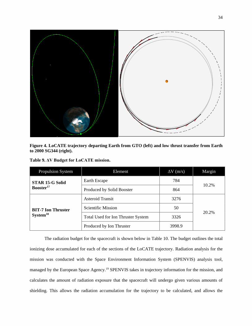
Figure 4. LoCATE trajectory departing Earth from GTO (left) and low thrust transfer from Earth
to 2000 SG344 (right).
Table 9. ΔV Budget for LoCATE mission.
Propulsion System Element ΔV (m/s) Margin
STAR 15-G Solid
Booster17
Earth Escape 784 10.2%
Produced by Solid Booster 864
BIT-7 Ion Thruster
System18
Asteroid Transit 3276
20.2% Scientific Mission 50
Total Used for Ion Thruster System 3326
Produced by Ion Thruster 3998.9
The radiation budget for the spacecraft is shown below in Table 10. The budget outlines the total
ionizing dose accumulated for each of the sections of the LoCATE trajectory. Radiation analysis for the
mission was conducted with the Space Environment Information System (SPENVIS) analysis tool,
managed by the European Space Agency.19 SPENVIS takes in trajectory information for the mission, and
calculates the amount of radiation exposure that the spacecraft will undergo given various amounts of
shielding. This allows the radiation accumulation for the trajectory to be calculated, and allows the

35
verification that the 100 krad total ionizing dose (TID) radiation requirement has been met. The TID
accumulated by the LoCATE trajectory is just under 48 krad, providing a margin of over 100%. There is
sufficient margin to complete another 12 orbits in GTO in case the completion of checkout is delayed and
the spacecraft cannot depart after the planned two orbits.
Table 10. LoCATE trajectory radiation budget, all values assumed 1 mm aluminum shielding.
Mission Segment Checkout and
Earth Escape
Asteroid
Transfer
Science
Mission
Total
Mission
Time Required (days) 11.3 650.0 50.0 711.3
TID (krad) 10.750 24.128 1.856 36.734 Margin
TID with 30%
Contingency (krad) 13.975 31.369 2.413 47.754
52.246
(109%)
C.2.2 Candidate Asteroids
LoCATE must visit an asteroid which presents a viable scientific target for human exploration and
is reachable by humans in the mid to late 2020s. Potential targets for the mission were selected from the
Near-Earth Object Human Space Flight Accessible Targets Study (NHATS), which summarizes asteroids
that have been considered as potential targets for human missions based on the transit time and ΔV
requirements to reach these asteroids. In order to limit operational costs, a maximum orbit transfer duration
of 750 days was set for the transfer between Earth escape and asteroid rendezvous.20 These targets were
then reevaluated based on the LoCATE mission requirements in order to determine which asteroids would
be viable within the constraints of the LoCATE mission.
A key factor in the target selection process is selecting an asteroid that will be a viable target for
human exploration in the late 2020s. A human mission will be much larger and more expensive, and high
ΔV requirements for the mission will increase the costs significantly. This creates a significant emphasis in
selecting a target with low ΔV requirements when humans would launch. This means that LoCATE would
need to launch prior to this optimal departure date in order to scout the asteroid, when the ΔV requirements
are not at their lowest.

36
The LoCATE mission will launch no earlier than January 1st 2022, and the mission will take almost
two years to complete, with the nominal trajectory requiring a total of 711.3 days to complete as noted in
Table 10. A human mission already in the planning process would require at least a year from launch to
lock in a target, so the chosen asteroid target should remain viable for at least three years after LoCATE
launch in order to allow time for mission planning. Any human mission to an asteroid would likely not
occur before the Asteroid Redirect Crewed Mission (ARCM) currently slated for late 2026, so a crewed
mission to an asteroid will likely occur in the late 2020s unless ARCM is canceled or postponed. Therefore,
the earliest that a human mission to the LoCATE target asteroid could be expected would be in 2025, if
there were no delays in either mission.
Over 80 targets from the NHATS
database and other sources were analyzed
resulting in the top four asteroid
candidates, 2000 SG344, 2011 UV136,
2013 BS45, and 2014 YD shown above in
Table 11. The ΔV requirements for each
asteroid are shown below in Figure 5 over the 2020-2028 period, with the ΔV capability of the spacecraft
noted with a dashed line. 2000 SG344 is a promising asteroid for a human mission, with a very close
approach in 2028 which makes it well suited for a human mission in the latter half of the 2020s. It is a more
difficult target to reach during the early 2020’s but the ΔV requirements during its close pass in 2028 make
it an appealing target for human missions due to the timing of this close approach with Earth. The asteroids
2011 UV136 and 2013 BS45 have a much lower ΔV requirement in the early 2020’s but this increases
slowly over time, making them less beneficial as targets for human exploration. 2013 BS45 has a
significantly larger variance in its ΔV requirements compared to 2011 UV136. There is a three-year period
where 2014 YD is a very easy target to reach, and it benefits from short transfer times. However, its ΔV
requirements only remain low for about three years, meaning that it would likely not be a viable target for
a precursor mission to a human exploration in this time frame.
Table 11. LoCATE final target candidates.5
Asteroid Estimated Size (m) Ideal Transfer Year
2000 SG344 20-89 2028
2011 UV136 14-62 2021
2013 BS45 11-51 2021
2014 YD 24-107 2025

37
Figure 5. ΔV required to reach candidate asteroids over time. The dotted line represents the
maximum ΔV capability of LoCATE
The asteroid 2000 SG344 is the easiest asteroid to reach in the late 2020s and it remains a viable
target in terms of required ΔV and transit time for much longer than the other asteroids. Therefore, 2000
SG344 has been chosen as the target for the LoCATE mission, as it allows LoCATE to tolerate significant
launch delays and presents a large window for human missions in the late 2020s.

38
Figure 6. Distance between asteroid candidates and Earth in the 2020s.
From a scientific standpoint, each of these asteroids are fairly equal in terms of value as targets. No
detailed surface images exist for any of the candidate asteroids. Each asteroid is of an unknown spectral
class, meaning that visiting any of these asteroids would provide knowledge of its composition.4 They are
all of similar sizes, with 2000 SG344 and 2014 YD being slightly larger than the other two, providing they
are of similar composition to one another. The communication distances for both asteroids are shown above
in Figure 6 through the graph of the distance between Earth and each of these final candidate targets. The
distance to the asteroid from Earth follows a similar trend to the ΔV required, so that for the easier to reach
asteroids, the data return rates will be correspondingly higher.
The possibility of the LoCATE spacecraft visiting additional targets was investigated in order to
increase the scientific return from the mission, and allow for characterizing multiple potential targets for
future human missions. If the LoCATE spacecraft can visit multiple targets it would present a significant

39
return on investment for the mission. Allowing the spacecraft to complete its scientific objectives at two
different asteroids would effectively double the value of the mission. However, this mission design was
ultimately not implemented due to the ΔV and time requirements associated with visiting multiple targets.
Visiting another target will significantly increase the length of the mission, by as much as a factor of two
or more, which would significantly increase the operations cost of the mission. The spacecraft has sufficient
ΔV to visit 2000 SG344, which is a very high priority target, and the only pairs of targets that could be
visited would be of lower priority. After the spacecraft has completed its primary mission, and if the
spacecraft is still in good health with sufficient propellant, the possibility of a mission extension to another
asteroid will be evaluated, but it is not a primary concern.
C.2.3 Trajectory Optimization
The trajectory of the LoCATE spacecraft must fulfill several key requirements, summarized in .
Table 12, which relate almost entirely to the cost, mass, and radiation requirements of the mission.
The spacecraft trajectory must not result in a significant radiation exposure, which has been accomplished
by limiting the total mission duration and the length of time spent in Earth orbit. The length of time in Earth
orbit has been limited by choosing a direct departure of Earth using a booster rather than using a low thrust
spiral departure. Limiting the duration of the mission also helps fulfill the requirement of limiting operations
cost, which is critical due to the cost requirement. The trajectory must also allow for a spacecraft dry mass
of over 100 kg in order to allow sufficient mass for the instruments and other spacecraft systems. The
minimum size of the spacecraft is bounded by the choice of scientific instruments.
Table 12. Requirements for the trajectory of the LoCATE mission.
# Trajectory Requirements
26.0 Spacecraft trajectory shall allow a spacecraft dry mass of over 100 kg
27.0 Spacecraft trajectory shall not result in operations costs above $15M
28.0 Spacecraft trajectory shall not expose bus to total ionizing dose greater than 100 krad
28.1 Limit time in Earth orbit to limit radiation exposure

40
The trajectory for the LoCATE mission has been optimized to minimize the amount of propellant
that is used by the spacecraft. This allows the spacecraft to support the largest dry mass possible while
meeting the mission constraints for time of flight and launch date. This optimization was conducted using
EMTG, an open-source, medium fidelity trajectory optimization software developed at NASA Goddard.
EMTG utilized monotonic basin hopping to search for globally optimal trajectories that meet the mission
constraints.21 In order to optimize trajectories quickly EMTG utilizes Sims-Flanagan transcription where
low-thrust trajectories are approximated as a series of discrete impulses rather than fully integrating the
trajectory. STK has been used to simulate Earth departure segments for the mission for the impulsive
transfer that was ultimately selected in addition to low thrust spiral trajectories which were considered. STK
fully integrates spacecraft trajectories, which is much more feasible for the Earth departure segments where
less optimization is required and higher accuracy simulation is desirable.
The low-thrust trajectory for the LoCATE mission accounts for the propellant utilization efficiency
of the BIT-7 thruster of 73%, along with a 30% ΔV margin applied onto the asteroid transfer trajectory.
The trajectory assumes the same 30% power margin used by the power system, although any additional
power generated by the spacecraft could be utilized by the propulsion system for additional performance.
The trajectory simulation accounted for a thruster duty cycle of 90%, which allows time for the spacecraft
to stop thrusting to communicate with Earth periodically. In addition, the duty cycle provides margin for
the trajectory in case the spacecraft enters safe mode or experiences some other malfunction preventing the
spacecraft from making the maneuver as scheduled.
A key factor in the choice of the type of trajectory for the LoCATE mission is the limiting of
radiation accumulation over the course of the trajectory. Higher amounts of ionizing radiation will require
more radiation shielding for the spacecraft components, components which are more radiation hardened, or
both. Both radiation shielding and radiation hardening will increase the cost of the mission. Furthermore,
not mitigating the radiation risk in at least one of these ways will significantly increase the risk of
component failures. Increasing the total mission time will increase the radiation dosage, but the most severe
radiation accumulation will occur during the period of time when the spacecraft is within the Van Allen

41
belts. The time that the LoCATE spacecraft spends in the Van Allen belts has been minimized by choosing
a shorter Earth escape trajectory, which as the most significant impact in TID accumulation of the mission.
There are two different types of trajectories that can be used to escape from Earth orbit. One is a
direct escape, which uses high thrust propulsion to complete an impulsive transfer which leaves the Earth’s
sphere of influence in a matter of days. The other is a low thrust spiral escape, which leaves Earth orbit
over the course of many months. A plot of each of these trajectories departing from GTO simulated in STK
are shown below in Figure 7.
Figure 7. Comparison of direct (left) and spiral (right) Earth escape trajectories departing from
GTO.
Different mission configurations are detailed below in Table 13, each shown with 1 mm of
aluminum shielding. The mission design that spirals from LEO has significantly greater radiation
accumulation than the other mission types, with the GTO spiral still experiencing significant radiation
accumulation. The GEO spiral has less radiation accumulation, but the launch cost for GEO is significantly
greater than for GTO or LEO. The GEO spiral mission has the disadvantage of requiring a much more

42
expensive launch reservation ($19.9M) and is a much rarer opportunity for secondary payloads. The cost
for each type of launch is shown below for a 300 kg launch allocation through Spaceflight Industries.
Table 13. Summary of the radiation accumulation for the Earth escape portion of the LoCATE
mission.
Mission Launch Cost
(Millions USD)
Earth Escape Time
(Days)
TID for Earth Escape
(krad)
LEO Spiral 7.950 466.2 1733
GTO Spiral 9.950 239.8 34.87
GEO Spiral 19.900 165.6 30.36
GTO Direct Departure 9.950 11.3 1.41
Departing from GTO and using a solid booster to escape rather than spiraling out incorporates the
benefits of a cheaper GTO with a reduced flight time and TID, even below the levels experienced during a
GEO spiral. Utilizing the solid booster and then an electric thruster to finish the transfer to the asteroid
significantly reduces the time spent in Earth orbit and the Van Allen belts. The direct departure significantly
reduces the radiation accumulation compared to the spiral trajectories, and allows for a similar dry mass
compared to the GTO or GEO spiral cases. This approach results in many of the benefits of a purely
impulsive trajectory, with the high efficiency of the electric propulsion system.
One of the most significant risks posed to the mission due to its use of a secondary launch allocation
is that the mission will be delayed. LoCATE will have very little control over the precise launch date of the
mission, and needs to be flexible in this regard. The electric propulsion system and examined targets will
allow the spacecraft to adopt only marginally different mission profiles in order to allow the mission to
proceed. This flexibility means that while LoCATE mission delays may cause a target change or a delay in
the human mission, it would not constitute a mission failure. Figure 5 shown in section C.2.2 illustrates this
flexibility, as the investigated targets show large viable launch opportunities that fulfill the LoCATE
mission requirements.

43
C.2.4 Launch Vehicle Analysis
Primary and secondary launch opportunities were discussed for the LoCATE mission. Launching
as a primary payload gives the mission significant flexibility in terms of trajectory choices as well as launch
dates. Launching as a secondary payload removes the option of specifying the initial orbit and launch date.
The extra flexibility from launching as a primary payload comes with a significantly higher cost, and most
launch vehicles are significantly too expensive for the $100M budget. However, a selection of some
affordable primary launch vehicles is listed below in Table 14.
Table 14. Summary of low-cost launch vehicle options.
Launch Vehicle Country Cost in FY2016 ($M) Payload to LEO (kg)
VEGA22 Italy 36.8 1430
SHAVIT23 Israel 25.3 800
PSLV23 India 16.3 3250
Pegasus24 USA 58.7 443
Even among the cheaper launch vehicles, many still present a significant cost and would
significantly increase the cost of the mission compared to utilizing a secondary launch opportunity. The
costs listed for these launch vehicles do not include the costs for payload integration, which would be
greater than for just integrating the spacecraft as a secondary payload. Most of the low-cost launch vehicles
are also through international providers, which would complicate the approvals process for the launch
vehicles, increase the cost, and present additional complications. Even the cheapest of the investigated
launch vehicles increases the launch costs of the mission, despite the fact that these launch vehicles would
allow for additional launch mass to LEO. Most of the additional mass margin that a launch vehicle would
provide would not be useful due to the fact that the spacecraft mass is largely limited due to cost. The high
energy performance of many of these launch vehicles would also result in diminished mass compared to a
secondary opportunity to GTO, although the high energy performance of the PSLV would result in an
increased mass capability to GTO. Due to the increased cost of launching as a primary payload, LoCATE
has chosen to launch as a secondary payload.

44
C.3 Spacecraft Subsystems
C.3.1 Attitude Determination and Control
Table 15. ADACS subsystem requirements.
# Attitude Determination and Control (ADACS) Requirements
29.0 Spacecraft shall determine attitude to within 0.1 degree accuracy
30.0 Spacecraft shall provide attitude control to within 1 degree pointing accuracy
30.1 Spacecraft shall provide 50 m/s of ΔV for attitude control
The attitude determination and control subsystem (ADACS) onboard LoCATE is responsible for
pointing the payloads’ sensors towards the scientific target and the antennas towards the Earth to maintain
a communications link. In order to do this, LoCATE must meet the pointing requirements of these
subsystems, which are much more lenient than most deep-space missions which use a parabolic dish with
very tight pointing requirements. Table 15 lists these requirements. Communications has the highest
constraint, due to its pointing requirements. Unlike a parabolic dish, horn antennas have a large half-power
beam width, which means there are no considerable pointing losses at small angle errors.25 In addition to
the mass of a parabolic dish, this is another reason why one was not chosen as the primary antenna for this
mission. Because of this and propulsion’s own requirements, the required ADACS pointing accuracy is
low. In order to meet the pointing requirements, a more accurate attitude determination must be in place.
The determination requirements are an order of magnitude less than the control system to ensure that
standard sampling errors do not affect the accuracy of the information given to the attitude actuators. It was
found that 50 m/s is required for the ΔV of LoCATE’s attitude control system. This is typically 3 to 6 m/s
of ΔV per year of attitude control per year, but that is including reaction wheels as a method of actuation,
which LoCATE will not implement for this mission.26 It was an early design decision that there would be
limited space and mass for reaction wheels on top of the requirements for the RCS onboard. To limit long
term propellant usage, the antennas are located on the Earth-facing side of the spacecraft so that little
maneuvering is needed to establish a link while in transit between Earth escape and rendezvous.

45
Table 16. Mass breakdown of ADACS components.
Item Unit Mass
(kg) Qty. Mass (kg)
Determination
Moog Mini Fine Sun Sensor27 0.05 6 0.30
Space Micro Miniature Integrated Star Tracker28 0.50 1 0.50
Control
Airbus 1N Monopropellant Thruster29 0.29 12 3.48
Moog VC03 Fill and Drain Valve30 0.05 2 0.10
Vacco V1E10763-01 Latch Valve31 0.34 1 0.34
Taber P4911 Pressure Transducer32 0.26 1 0.26
Vacco F1D10639-01 Filter33 1.00 1 1.00
Hydrazine Tank26 1.71 1 1.71
Propellant 1.00 6 6.00
Total Mass 13.69 kg
As shown in Table 16 above, the determination segment of ADACS consists of six sun sensors and
a star tracker module that has two cameras perpendicular to each other. While the star tracker would be
enough for obtaining the required determination accuracy, component failure would hinder LoCATE’s
ability to point. Therefore, placing lightweight sun sensors on all 6 sides of the spacecraft provides coarser
determination accuracy. The sun sensors also act as the determination system in emergency mode, as it is
composed of passive components.
The control segment consists of 12 hydrazine-fueled 1 N thrusters on four of the six sides of the
spacecraft. The thruster configuration is in Figure 8, designated by the yellow cylindrical components. Four
thrusters are not shown in this image, but are facing outward from the viewer on the hidden side of the
spacecraft in the same configuration. The remaining components in the Control section of Table 16 are the
support equipment required to control flow and measure the health of the subsystem. These were chosen
based on mass and propellant mass flow rates, as the valves and filters were nearly indistinguishable
between manufacturers.

46
Figure 8. ADACS exterior component configuration.
In order to obtain the amount of propellant and tank size for the propellant, the rocket equation was
used to find that approximately 5 kg of hydrazine, 6 kg with ΔV margin, was necessary to meet the 50 m/s
at the thrusters’ specific impulse of 220 s. 6 kg of hydrazine at 293 K, it will take just under 6 liters of
volume; in a spherical tank, this will have a radius of 12 cm. Mass sizing of the propellant tank came from
historical averages of mass versus volume of propellant tanks.26 1.71 kg was the calculated mass of the
propellant tank. A pressurant tank is not included in ADACS sizing because the main propulsion’s tank
will link to the attitude control system. This shows that requirement 30.1 is met, since the system was
designed for 50 m/s of ΔV.
Table 17. Determination component accuracies.
Determination Power Accuracy
Fine Sun Sensor27 Passive 0.2 degrees
MIST (Star Tracker)28 3 W 30 arcseconds

47
As shown in Table 17, MIST’s accuracy shows that it can meet the determination accuracy
requirement by almost two orders of magnitude. The sun sensors are only 0.1 degrees more than the
requirement for normal operation of the satellite. Not only are they redundant, they provide high levels of
accuracy. The attitude control accuracy requirement is an accepted value of one degree, which is around
the capability of propellant based systems.26 This number will be verified with a series of simulations and
moment of inertia studies.
C.3.2 Command and Data Handling (C&DH)
Table 18. C&DH subsystem requirements.
# Command and Data Handling (C&DH) Requirements
33.0 Spacecraft shall process all data it receives (and transmits) for storage or communication
33.1 C&DH shall provide attitude data to necessary subsystems and ground segment operators
33.2 C&DH shall provide spacecraft health related data to the ground segment operators
33.3 C&DH shall store 24 hours of payload data onboard
33.4 C&DH shall encode and decode all data involved in transmissions sent or received
Command and data handling (C&DH) is the core of operations for LoCATE, even before separation
from the launch vehicle. Subsystem requirements have been defined and are summarized in Table 18. The
subsystem is responsible for smooth operation not only between subsystems, but also between the ground
and space segment of the mission. It is the computational center of any subsystem that does not have a
dedicated processor. For example, the sun sensors do not have any form of built in processing, but rely on
lookup tables, provided and integrated with C&DH before launch. This allows the sensors to accurately
measure the attitude in case of star tracker fault. Since C&DH interfaces with every other subsystem, each
system will provide C&DH with data pertinent to nominal operation to ensure proper system functioning.
This data is then regularly relayed back to Earth so that the operators know that LoCATE is working. The
C&DH system is responsible for onboard data storage. All outgoing and incoming transmissions go to the
communications subsystem first and are then decoded by the C&DH computer. Furthermore, C&DH will

48
provide both modulation and forward error correction processes for maintaining a strong link between
LoCATE and Earth.
Table 19. Mass breakdown of C&DH components.
Item Unit Mass (kg) Qty. Mass (kg)
Space Micro Proton 2X Box34 3.5 1 3.5
P400K Processor ----- 2 -----
Flash Storage Module ----- 1 -----
Digital I/O Module ----- 1 -----
Analog I/O Module ----- 1 -----
Power Supply ----- 1 -----
Wiring 0.5 1 0.5
Total Mass 4.0 kg
Table 19 shows the mass breakdown of C&DH, which is a singular housing for the computing
capabilities as well as some mass allocated for wiring. Space Micro makes a lightweight, modular computer
known as the Proton 2X Box for C&DH applications. Some components in other subsystems are have
dedicated processing, allowing the design to cater more towards operations that do not currently have
independent processing power available. The box has room for six different component boards operating
in tandem on three difference levels.34
Immediately after launch, LoCATE must first report that the entirety of the spacecraft is healthy
and functioning normally. This diagnostic information must show that everything is working well and
mitigate any issues that arise or risks that take shape in the final design. The diagnostic information will be
sent regularly to the ground segment operators, as well as attitude information. Relaying this data regularly
will give operators a chance to fix a problem before one occurs. With this information, avionics data will
be sent to make sure the trajectory of the spacecraft is the intended one. This fulfills requirement 33.2 and
33.3.
By occupying two of the modules with high performance, 100 krad resistant Proton 400k
processors, the system gains valuable robustness. Since a processor failure could be mission ending,

49
choosing to install two of these processors creates redundancy of a mission critical component. The P400k
dual-core processors will focus on handling the computationally expensive task of calculating attitude states
and controls. The processors also convert the signals for the communications system, and are responsible
for the handling of sent and received data. Raw experimental data from the various payloads will be stored
directly on the flash storage module, which is scalable up to 256 GB.34 256 GB is more than enough to store
24 hours’ worth of LoCATE scientific experimental data and will not add extra weight, so it will be
implemented in order to meet requirement 33.3.
The star tracker on LoCATE has its own processing unit built in, but the sun sensors lack the
capability to independently determine the attitude of a spacecraft. The sun sensors will be connected to the
C&DH housing via the analog I/O board. As the data enters the system, the computer will discretize it into
digital information. A lookup table will be implemented in order to bring the accuracy of LoCATE’s
pointing down to 0.2 deg. Given this data and the data produced by the star tracker, attitude in the orbital
frame can be fully constrained for measurement. The body estimation, in addition to the actuation of the
reaction control system, calls for the implementation of a Kalman filter for those actions.
For the communication section of C&DH, it is necessary to decode any modulation and forward
error correction and translate it into digital signals that can read by the computer itself or encode it to send
to someone else. As shown in section C.3.3, LoCATE shall communicate using a 7/8 QPSK encoding and
modulation scheme in order to get a more substantial link margin and lower the bit error rate to under 10-5
symbols/second. The processor onboard will be able to handle QPSK modulation and a parity bit for every
14 bits of data (7 symbols) and will not face many issues. This fulfills requirement 33.4 for the design of
LoCATE’s C&DH subsystem.
C.3.3 Communications
The communications subsystem of LoCATE is responsible for maintaining a linkage between Earth
and the spacecraft. The system must send the ground operators both attitude and subsystem data in addition
to the ultimate focus of the mission: scientific data. As shown in Table 20 below, a series of requirements
drives the design. LoCATE uses the Deep Space Network (DSN) for more than 99% of the mission, but

50
cannot be used while LoCATE is within the radius of a geostationary orbit, which is approximately 43,000
km. This prompts the usage of the Near Earth Network (NEN) until LoCATE is on a trajectory exiting the
Earth’s gravitational influence. After initial checkout, sending health-related information (attitude data,
subsystem statuses) on a regular basis necessary because the mission is at its peak risk stage. After the
booster is expended and jettisoned, LoCATE gains distance from Earth, forcing the DSN to be the mode of
communication while allowing a decrease in check-ins to at least once per day.
Table 20. Communications subsystem requirements.
# Communications Requirements
31.0 Spacecraft shall be able to communicate with both the NEN and DSN
31.1 Spacecraft shall use the Near Earth Network for communication prior to Earth escape
31.2 Spacecraft shall use the Deep Space Network for communication after Earth escape
31.3 Spacecraft shall have a link margin of 2 dB or 20% of the required Eb/N0 for linkage,
whichever is greater.
31.4 Spacecraft shall transmit scientific data with a bit error rate (BER) of less than 10-5 incorrect
symbols/second
31.5 Spacecraft shall transmit scientific data at a rate of no less than 1000 symbols per second (1
ksps)
31.6 Spacecraft shall implement a secondary, low-gain antenna system
Requirements 31.3 to 31.6 are important for maintaining an adequate signal. At a minimum of 2
dB of link margin, LoCATE can safely avoid losing signal from random events that may affect the received
Eb/N0. Selection of the required Eb/N0 depends solely upon the bit error rate (BER) of a selected
modulation and error correction scheme. 10-5 errors per second allows for approximately one error per
month (transmitting for an hour a day), which is infrequent enough to warrant a retransmission of data, if
necessary. The extra power from establishing a link margin will ultimately lower the BER from this value.
To tighten the drivers for design, 1000 symbols per second is the minimum communication speed needed
for achieving a reasonable transfer rate for the scientific data collected. This is a guideline for the minimum,
not a ceiling on the maximum; the symbol rate will increase as the range between Earth and LoCATE
decreases after asteroid rendezvous. The final requirement in Table 20 is to include a low gain antenna on

51
LoCATE in order to improve fault tolerance in case of primary system failure, as well as act as the
communication system for the NEN.
Table 21. Mass breakdown of communications system.
Item Unit Mass (kg) Qty. Mass (kg)
ATM Microwave 20 dB Horn25 1.65 1 1.65
AntDevCo Single Frequency Patch Ant.35 0.12 2 0.24
Thales X-Band Transmitter36 1.37 1 1.37
Small Deep Space Transponder37 3.20 1 3.20
Thales X-Band TWT Amplifier38 2.50 1 2.50
WR 112 Waveguides 1.00 1 1.00
Wiring 0.30 1 0.30
Total Mass 10.26 kg
As seen in Table 21 above, a horn antenna is the primary antenna, but is used only for transmission
of data in the deep space region. A deployable parabolic dish was considered, but was ultimately rejected
because of the unnecessary risk that would be added to the mission, as well as the aforementioned size and
mass constraints. The two single-frequency patch antennas, produced by AntDevCo, serve three purposes:
the backup system in case of fault, the receiver for all communication sent to LoCATE, and the
communication interface for the NEN. These patch antennae fulfill requirements 31.1 and 31.6 in Table 20.
The next three components in Table 21 presuppose that LoCATE’s band selection is the X-band.
When selecting a transmission band, the first consideration was the availability of bands through the DSN.
The list narrowed down to X, S, and Ka bands.39 Ka bands are susceptible to considerable rain fade that
LoCATE could not afford. Consequently, that option was eliminated. The final decision came down to the
size of the antenna for each band. An antenna with identical gain would require the length of the horn
antenna to be increased to 100 cm from approximately 25 cm.25 LoCATE’s size could not accommodate
that large of an antenna, so the X-band was the final band choice. The Thales X-band transmitter and TWT
amplifier are both flight proven hardware with a sizeable heritage, helping lower cost and risk in the
mission. The antenna and TWT amplifier have efficiencies of 0.52 and 0.5, respectively. The final major
component is the Small Deep Space Transponder, which will provide the capabilities of receiving uplinked

52
data and sending the beacon signal for the health information of the spacecraft using one of the patch
antennas. This transponder has an extensive heritage and was designed by JPL for deep space applications,
making it the perfect low mass option for LoCATE.37 The remaining components will accommodate all
connections between components within communications and interfaces with other subsystems,
particularly command and data handling.
The space segment of the communications subsystem keeps both the capabilities of the NEN and
DSN at the forefront of its design. LoCATE satellite’s downlink frequency is 8450 MHz while the uplink
frequency is 7195 MHz. These are values supported by both the NEN and DSN. With the NEN, all but a
few stations have X-band telemetry capabilities, but there are only two stations that have command
capabilities: Dongara, Australia and South Point, Hawaii.40 However, command is not needed regularly;
telemetry is more important at the beginning of the mission. Command will be required for telling LoCATE
when to begin firing the booster stage and fix any problems that may arise during checkout. The lowest
antenna gain at any X-band NEN station is 54 dBi and the lowest effective isotropic radiated power (EIRP)
is 51 dBWi, both of which are at the TrollSat station in Antarctica.40 These values are the worst-case
scenario and the link budget calculations use them to make sure LoCATE is capable of using any X-band
equipped station in the NEN for telemetry. The NEN characteristics are shown in Table 23 below.
The DSN has two options for antennas to choose from, 70 m and 34 m. From a costing perspective,
70 m should only be used as a last resort, as it increases the cost of using a 34 m antenna fourfold and is
generally reserved for missions that have ranges exceeding that of the asteroid belt. 4 m antennas which
come in high efficiency (HEF) and beam waveguide (BWG) modes are available at all three DSN locations,
and most operate in the X-band.39

53
Table 22. DSN Characteristics Table 23. NEN Characteristics
Ten antennas operate at a transmitting power of 20 kW. One at Goldstone that operates at 80 kW,
antenna DSS-26. 80 kW is more than what is necessary, but is valuable for situations such as emergency
mode activation. The minimum values for Gain (dBi) and EIRP (dBW) are 68.2 and 89.5, respectively, and
will be considered the worst-case in calculating the link budgets. There is also Doppler ranging that will
use the Doppler effect to calculate speed and distance, which will be used with ADACS to create a de facto
guidance, navigation, and control system. Table 22 shows the characteristics of the DSN.39
The worst case for transmitting to the DSN will be at the furthest distance SG344 during the
window in which the mission can take place. Prior to that, the worst case for the NEN is when LoCATE is
at the apogee of GTO. Atmospheric losses are the maximum possible, calculated at 10 degrees above the
horizon compared to the vertical losses of 20 km. All of the other data provided below comes from the DSN
Link Design Handbook, NEN User’s Guide, or information from other, similar missions.
Table 24. Ground Segment Losses Table 25. System noise characteristics
DSN Info39
Minimum Gain 68.2 dBi
Minimum EIRP 89.5 dBWi
Noise Temp 33 K
Line Losses 0.25 dB
Pointing Losses .15 dB
DSN Efficiency 0.7
NEN Info40
Minimum Gain 54 dBi
Minimum EIRP 51 dBWi
Noise Temp 33 K
Line/Point Loss 5 dB
Primary Losses
Pointing loss 0.25 dB
Free-space path loss varies
Line Losses -1 dB
Atmosphere Attenuation26 1.3 dB
Noise
System Noise Temp 50 K
Noise density -211.61 dB

54
Table 25 details the noise temperature of the entire system, 33 K is the DSN’s contribution, while
the remaining 17 K is a rough estimate of LoCATE’s noise temperature. Table 24 displays the various
losses that are well documented for the DSN, aside from the free-space path loss. The free-space path loss
is the largest loss, so calculating from the largest distance encountered by each section of the mission is
necessary. The furthest from the NEN LoCATE will reach is approximately 25,000 km, which is the
equivalent of a space loss of 202.02 dB for an uplink and 198.72 dB for a downlink. The furthest from Earth
LoCATE will reach is approximately 175 million km, which is the equivalent of a space loss of 275.81 dB
for downlinks and 274.38 dB for uplinks.
It was necessary to iterate different link budgets in order to meet requirements 31.4 and 31.5.
Starting with the binary phase shift keying (BPSK) encoding, where the required Eb/N0 = 9.5 for a BER
equal to 10-5, the power required to achieve that signal strength was too high for 1 ksps. Implementing 7/8
forward error correction (FEC) and switching to quadrature phase shift keying (QPSK) were the next step
in the design iteration.26 This decreases the required Eb/N0 from 9.5 to 4.4 dB while only sacrificing 1/8 of
the data transmitted. When operating at the maximum possible power, the signal for 1 ksps can be shown
in Table 26.

55
Table 26. Science downlink budget at 160 W input,
166 million km, 1 ksps, and 8450 MHz.
Value Value, dB
LoCATE Transmitter
Power Transmitted 42 16.19
Antenna gain 100.00 20.00
Line loses 0.79 -1.00
EIRP 5237.13 37.19
Environmental Losses
Pointing 1.06 0.25
Space 3.45E+27 275.38
Atm. Attenuation 1.35 1.30
Total Loss 4.93E+27 276.93
DSN Receiver
Antenna gain 6.61E+06 68.20
Line losses 1.06 0.25
Power 6.62E-18 -171.79
Energy per bit (Eb) 6.62E-21 -201.79
Noise
System noise temp. 50.00 16.99
Noise density (N0) 6.90E-22 -211.61
Total
Received Eb/N0 9.60 9.82
Required Eb/N0 2.75 4.40
Link margin 3.48 5.42
Because at least 2 dB of link margin is in place, 1 ksps achieved, and an error rate of 10-5 has been
reached, LoCATE’s communications subsystem qualifies as a success for verifying the requirements 31.4,
31.5, and 31.6. The remaining transmitting/receiving modes all qualify, as this has the smallest margin
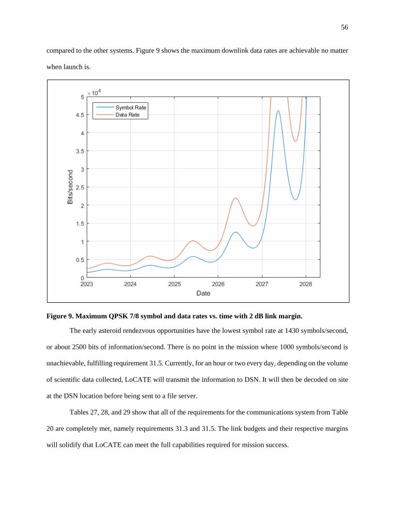
56
compared to the other systems. Figure 9 shows the maximum downlink data rates are achievable no matter
when launch is.
Figure 9. Maximum QPSK 7/8 symbol and data rates vs. time with 2 dB link margin.
The early asteroid rendezvous opportunities have the lowest symbol rate at 1430 symbols/second,
or about 2500 bits of information/second. There is no point in the mission where 1000 symbols/second is
unachievable, fulfilling requirement 31.5. Currently, for an hour or two every day, depending on the volume
of scientific data collected, LoCATE will transmit the information to DSN. It will then be decoded on site
at the DSN location before being sent to a file server.
Tables 27, 28, and 29 show that all of the requirements for the communications system from Table
20 are completely met, namely requirements 31.3 and 31.5. The link budgets and their respective margins
will solidify that LoCATE can meet the full capabilities required for mission success.

57
Table 27. Uplink budget at 20 kW DSN 34 m, 166
million km range, 1ksps, and 7190 MHz.
Value Value, dB
DSN Transmitter
Power Transmitted 2.00E+04 43.01
Antenna gain 6.61E+06 68.20
Line loses 1.06 0.25
EIRP 1.25E+11 110.96
Environmental Losses
Pointing 1.06 0.25
Space 2.50E+27 273.98
Atm. Attenuation 1.35 1.30
Total Loss 3.57E+27 275.53
LoCATE Receiver
Antenna gain 3.98 6.00
Line losses 0.79 -1.00
Power 9.73E-17 -160.12
Energy per bit (Eb) 9.73E-20 -190.12
Noise
System noise temp. 50.00 16.99
Noise density (N0) 6.90E-22 -211.61
Total
Received Eb/N0 141.07 21.49
Required Eb/N0 2.75 4.40
Link margin 51.22 17.09

58
Table 28. LoCATE NEN TT&C downlink budget
at 42,000 km range.
Value Value, dB
LoCATE Transmitter
Power 1.00 0.00
Antenna gain 3.98 6.00
Line loses 0.63 -1.00
EIRP 3.28 5.16
Environmental Losses
Pointing 1.00 0.00
Space 2.23E+18 183.49
Atm. Attenuation 1.35 1.30
Implementation 1.26 1.00
Total Loss 3.79E+18 185.79
NEN Receiver
Antenna gain 2.51E+05 54.00
Line losses 1 0.00
Antenna efficiency 0.7 N/A
Power 2.18E-13 -126.63
Energy per bit (Eb) 2.18E-16 -156.63
Noise
System noise temp. 50 16.99
Noise density (N0) 6.90E-22 -211.61
Total
Received Eb/N0 3.15E+5 54.99
Required Eb/N0 2.75 4.40
Link margin 1.14E+5 50.59

59
With an Eb/N0 of 21.5, encoding is not necessary for this signal, even at the furthest LoCATE will
be from Earth. However, it will still be implemented to limit the amount of aperture time needed for
operations. FEC-free and uncoded 16PSK is a possibility, limiting the link margin to 4 dB with a required
Eb/N0 of 17.5 dB. This is greater than the 20% needed from the requirements.26 Shown in Table 28, the
NEN uplink/downlink budgets have substantial amounts of margin in their link budget that even minimal
power will be enough to establish a 1 ksps link at the apogee of GTO.
Table 29. LoCATE NEN TT&C uplink budget at
42,000 km range.
Value Value, dB
NEN Transmitter
EIRP 1.26E+05 51.00
Environmental Losses
Pointing 1.06 0.25
Space 1.61E+20 202.08
Atm. Attenuation 1.35 1.30
Total Loss 2.30E+20 203.63
LoCATE Receiver
Antenna gain 6.61E+06 68.20
Line losses 0.79 -1.00
Power 4.54E-09 -83.43
Energy per bit (Eb) 4.54E-12 -113.43
Noise
System noise temp. 50.00 16.99
Noise density (N0) 6.90E-22 -211.61
Totals
Received Eb/N0 6.59E+09 98.19
Required Eb/N0 2.75 4.40
Link margin 2.39E+09 93.79

60
With this large of a link margin in Table 28, potential data transfer speeds exceed the maximum of
the ground infrastructure. So operating the patch antenna at 1 Watt will suffice as only spacecraft health
related data is sent back to the ground operators. The margin is even greater when uplinking, as seen in
Table 29. Table 29 uses the EIRP, because gains are not provided.
As shown in the four link budgets, a bit error rate of less than 10-5 error/second and a symbol rate
of at least 1 ksps are both achievable during any segment of the mission and will allow for a large enough
margin to safely transit through space with a very slim chance of loss of contact. This verifies that
requirements 31.1 and 31.2 have been fulfilled, completing all of the requirements set for the subsystem.
C.3.4 Propulsion
The propulsion system for the LoCATE spacecraft must fulfill critical requirements for the mission.
The propulsion system must produce sufficient ΔV at a high enough thrust level to allow LoCATE to
conduct its mission and complete its scientific objectives. The requirements for the LoCATE propulsion
system are summarized below in Table 30, outlining the performance required by system.
Table 30. Propulsion subsystem requirements.
# Propulsion System Requirements
22.0 Spacecraft propulsion system shall provide 784 m/s ΔV for GTO escape maneuver
23.0 Spacecraft propulsion system shall provide 3276 m/s ΔV for the asteroid transfer.
24.0 Spacecraft propulsion system shall provide 50 m/s ΔV for station-keeping upon arrival
and throughout scientific operations
The propulsion system for the LoCATE spacecraft will consist of two parts: a solid rocket motor
for Earth escape, and an electric propulsion system to allow the spacecraft to transfer to the asteroid after
reaching escape. These two systems are summarized below in Table 31, with specific breakdowns and
analysis shown farther below. The solid rocket motor will be an Orbital ATK STAR 15G motor, which will
be activated at perigee of the geostationary transfer orbit and jettisoned after use. The spacecraft will then
utilize its 3 BIT-7 ion thrusters to complete the transfer from escape to the target asteroid. The electric
propulsion system will be used to rendezvous and maneuver in the vicinity of the asteroid while the

61
spacecraft competes its scientific objectives. The xenon tank for the ion thrusters is connected to the
pressurant system, which also services the hydrazine tank used by the ADACS. A diagram illustrating the
layout of the propulsion and ADAC systems is shown below in Figure 9.
Figure 10. Configuration of the propulsion and ADAC Systems.
Table 31. Summary of the propulsion system of the LoCATE spacecraft.
Propulsion System Max
Thrust ISP (s)
System Dry
Mass (kg)
Propellant
Mass (kg)
Maximum
Propellant (kg)
STAR 15G Solid
Motor17 12.45 kN 281.8 14.14 59.42 79.78
BIT-7 Electric
Propulsion
System18
33 mN 3500 16.5825 21.40 48.735
A STAR 15G motor has been chosen for the LoCATE mission due to its simplicity, as well as
lower mass and lower cost than a liquid monopropellant or bipropellant system. A monopropellant system

62
could be used for Earth departure instead of a solid stage, but a larger propulsion system would be required
compared to a solid booster. A monopropellant system would increase the complexity, cost, and risk of the
mission, due to the extra components and development time required. Shown below in Table 32 is a
comparison between the masses of different propulsion systems considered for each of the thruster options.
Using a monopropellant or bipropellant system for the booster results in higher propulsion system masses
for the escape stage. Both systems would also be both more complex and more costly than a solid motor
which can be bought and integrated much more simply, making the choice of a solid booster for Earth
escape quite simple.
Table 32. Comparison of LoCATE Earth escape stage options.
Propulsion System Type ISP (s) Propulsion System Mass (kg)
STAR 15G17 Solid 282 93.91
MR-104A/C 440N41 Hydrazine
Monopropellant 239 121.75
HiPAT 490N42 MMH/NTO Bipropellant 320 98.63
If the spacecraft mass is lower than the value accounted for through margin, either a smaller booster
can be utilized, or the booster can be loaded with less propellant to lower the impulse provided. The 59.42
kg partial loading which was been selected has been tested by Orbital ATK in the past, and would allow
for additional propellant to be loaded if required. Ballast mass could also be added to allow for larger
propellant loadings to be used, in order to lower the velocity change provided by the motor to the desired
level. The motor has been slightly oversized to account for potential losses that will occur during the
maneuver due to pointing or due to small variances in the actual impulse provided by the booster. This will
ensure that the spacecraft will reach escape using the booster, and the booster itself will also reach escape
and will not remain in Earth orbit or pose any type of hazard. Even if the spacecraft is just short of escape
after using the booster, the booster will not remain in Earth orbit long due to perturbations from the Moon.
Any minor variations in the final trajectory will be easily correctable by the propellant margin in the electric
propulsion stage.

63
Table 33. Mass breakdown of the electric propulsion system for the LoCATE spacecraft.
Component Number Unit Mass (kg) Mass (kg) Mass With Contingency (kg)
BIT-7 Thruster 3 2.8 8.4 8.820
Pressurant Tank 1 0.5 0.5 0.625
Orbital ATK 80421-1
Propellant Tank43 1 1.93 1.93 2.027
Power Conversion
Unit44 1 2.8 2.8 3.220
Propellant Valves 4 0.29 1.16 1.450
Busek BHC-1500
Cathode45 3 0.14 0.42 0.441
Total Dry Mass 15.21 16.583
The mass breakdown for the electric propulsion system is shown above in Table 33, which includes
the thrusters, the power conversion unit, and the tanks and valves required for propellant storage. The
majority of the dry mass comes from the electric thrusters and tanks, and the propellant will add another 30
kg to the system. The cylindrical propellant tank has been sized to handle 48.7 kg of propellant. This
oversizing was done both to provide sufficient margin, and to allow for loading the tanks with more
propellant in the event that a larger ΔV margin was desired.
In order to select the electric propulsion system to be utilized by the spacecraft, different thrusters
were investigated to determine which would require the least amount of propellant to complete the required
scientific mission. The propellant mass required by each propulsion system is shown below in Table 34
along with the relevant properties of each thruster. Each of these different electric propulsion systems
assume the ΔV requirements, which will be very similar, as the number of thrusters was chosen to have a
similar thrust level. As a first order analysis, these thrusters were compared with parametric estimation,
before any component selection was completed for any of the other parts of the propulsion system. The
three thrusters evaluated were the BHT-200 and BHT-600 Hall thrusters as well as the BIT-7 ion thruster,
and the results are shown below in Figure 11.18,46-48 The Hall thruster options require significantly greater

64
propellant mass due to their lower specific impulse, as well as having lower thruster lifetimes compared to
the ion thrusters due to cathode erosion.49-50 This lower lifetime increases the risk of thruster failure and the
risk of the mission. Each of these factors contributed to the choice of the BIT-7 ion thruster over one of the
Busek Hall thrusters.
Table 34. Comparison of electric propulsion systems sized to provide 4550 m/s ΔV.
Thruster Number of
Thrusters
Xenon Propellant
Mass Required
(kg)
Nominal Power
Per Thruster
Nominal Thrust
Per Thruster
(mN)
Nominal
Specific
Impulse (s)
BHT-200 4 84.6 200 13 1375
BHT-600 2 73.86 600 39 1500
BIT-7 3 29.17 360 11 3500
Figure 11. The three electric thrusters considered for the LoCATE mission, the BHT-200 (left), BHT-
600 (center), and the BIT-7 (right).
C.3.5 Power
The LoCATE spacecraft requires an electrical power system (EPS) capable of continuous power
generation, storage, and distribution. The EPS must also carry out any necessary power conversions and
monitor system health. To meet these requirements, the EPS will consist of a primary power source, an

65
energy storage device, and power processing system. Power system sizing is derived from the peak power
requirements of the LoCATE spacecraft. A complete list of EPS requirements is shown in Table 35 and
drives the EPS design.
Table 35. Power subsystem requirements.
Table 36. Power budgets for each operational mode showing the power requirements for each
system.
System Maneuver (W) Science (W) Transmit (W) Idle (W)
Payload 0.0 30.0 0.0 0.0
ADCS 21.0 84.0 84.0 3.0
C&DH 27.0 27.0 27.0 27.0
Communications 0.0 0.0 51.0 16.0
Propulsion 600.0 0.0 0.0 0.0
Power 15.3 15.3 15.3 15.6
Structures 0.0 0.0 0.0 0.0
Thermal 117.1 27.6 31.3 10.9
Total 780.4 183.9 208.6 72.4
30 % Margin 234.1 55.2 62.6 21.7
Total with Margin 1014.5 239.1 271.2 94.2
# Electrical Power System (EPS) Requirements
14.0 Spacecraft shall meet the power demands of each operational mode
14.1 EPS shall generate a minimum of 1014.5 W of power supply
14.2 EPS shall provide power to spacecraft before and after Earth escape
14.3 EPS shall store 241.4 Whr of energy for operations during eclipse periods
15.0 Spacecraft shall provide power to each component
15.1 EPS shall regulate and distribute power to each component as necessary
15.2 EPS shall include a fault protection and health monitoring system

66
The LoCATE mission features four operational modes: Maneuver, Science, Transmit, and Idle.
The Maneuver mode refers to when the spacecraft is using its electric propulsion system, primarily during
the transit period from GTO to asteroid rendezvous. The spacecraft will enter Science mode when payload
instruments are activated in order to collect data. Transmit mode refers to the downlink of science data.
Lastly, the spacecraft will remain in Idle mode when neither the medium gain antenna, payload, nor
thrusters are activated. The power requirements vary for each mode, since different combinations of
spacecraft systems will be operational. The peak power requirements come from the Maneuver mode, due
to the ion engine input load. With a 30% margin, this peak power requirement is 1014.5 W. The EPS design
assumes a mission lifetime of three years. Table 36, shown above, outlines the power budgets for each
operational mode.
The first major design consideration regarding the EPS is selecting the primary power source.
Typical power source options for small spacecraft are primary batteries, photovoltaic solar cells, or fuel
cells.26 However, both primary batteries and fuel cells are incapable of surviving a three-year mission, and
can therefore be ruled out. When considering the mission budget, the only affordable option capable of
providing sufficient power over a course of the LoCATE mission is photovoltaic solar cells.
Table 37. Array sizing for common cell types based on mission and power
requirements.
Design Parameter Si GaAs GaAs Triple-Junction
Cost ($) per Watt 378 852 617
Efficiency 22% 28.5% 30%
Power Output (W/m2) 277.1 233.0 377.8
Power at BOL (W/m2) 207.8 174.7 283.4
Life Degradation 0.89 0.92 0.99
Power at EOL (W/m2) 185.3 160.7 279.1
Area Required (m2) 6.44 7.43 4.28
Mass Density (kg/m2) 1.45 1.69 1.76
Mass (kg) 9.34 12.55 7.53

67
Common solar cell types include silicon, gallium arsenide (GaAs), and triple-junction GaAs.
Silicon cells are less expensive, but more susceptible to radiation degradation. Triple-junction GaAs cells
are the most efficient, followed by silicon cells. From the current mission requirements, the solar array can
be sized for each cell type. For a peak power requirement of 1014.5 W and a distribution efficiency of 85%,
the solar panels must generate a total of 1193.5 W. The maximum expected distance from the sun is 1.043
AU, therefore the minimum solar flux is 1259.4 W/m2. This power sizing assumes a negligible cosine loss
and an inherent degradation of 75%. Table 37 summarizes the solar cell sizing for each cell type.
The LoCATE spacecraft is subject to a volumetric constraint of 125x100x100 cm3 due to secondary
payload requirements. Therefore, these array sizes necessitate deployable solar arrays. Additionally, due to
the 300 kg wet mass constraint, minimizing the mass of the power system is critical to the mission design.
The additional mass required for silicon or GaAs cells is too significant to justify potential cost savings,
therefore triple-junction GaAs cells were selected.
The cells will be attached to a retractable rectangular panel, which will be safely folded and stored
during launch. Following separation from the launch vehicle, the solar panels will deploy and provide power
to the LoCATE spacecraft during the diagnostic period. Once checkout is complete, the panels will retract
into a safe position in preparation for igniting the booster stage. After the booster stage has completed its
burn and has been detached, the solar panels will re-deploy for the remainder of the LoCATE mission.
The use of solar cells for power generation requires an energy storage option for eclipse periods.
High energy density batteries are the modern standard for spacecraft power storage as an affordable and
lightweight technology capable of surviving years of discharge cycles in the space environment. Battery
sizing for the LoCATE mission is a function of eclipse power requirements and duration. The peak eclipse
period for the spacecraft occurs during the GTO checkout period. The eclipse time for the expected
checkout orbit is 0.923 hours, during which the spacecraft will operate in Idle mode and draw a maximum
of 94.2 W. For a depth-of-discharge of 40% and a transmission efficiency of 0.9, the peak required energy
capacity of the storage system is 241.4 Whr.

68
Table 38 shows the battery mass necessary to meet this requirement for three common battery
types: Nickel Cadmium (Ni-Cd), Nickel Hydrogen (Ni-H2), and Lithium Ion (Li-Ion).
Table 38. Sizing for common battery types based on mission
and power requirements.
Design Parameter Ni-Cd Ni-H2 Li-Ion
Energy Density (Whr/kg) 30 60 125
Mass (kg) 8.05 4.02 1.93
The Li-Ion requires the least amount of mass to store the necessary energy. Combined with the high
recharge efficiency, low self-discharge rate, volumetric savings, reliability, and ease of manufacture, Li-
Ion batteries are the clear choice for energy storage.
The EPS will also include a processing unit and wiring system capable of controlling power
regulation, power distribution, monitoring system health, and controlling solar panel orientation. The
processing unit will implement a peak power tracker (PPT) system, which utilizes a DC-DC converter in
series with the solar array and batteries to monitor and control power generated by the solar cells. The
batteries will be charged in parallel for simplicity and cost savings, and a control loop will prevent
overcharging. The EPS processor will include a switch-mode voltage regulator to bring power loads to
required specifications for each system. This includes regulation of voltage and current for each spacecraft
component. A network of cabling and load switches will be routed throughout the spacecraft to distribute
power. Commands sent from the main spacecraft processor will notify the EPS processor of which
components require power. Fault protection systems are designed to detect and isolate faults to minimize
damage to the spacecraft. Fuses placed throughout the wiring system will inform the processing unit of any
short circuits. In the case of a detected fault, the processing unit will notify the main spacecraft computer,
which will send a signal to the LoCATE ground team. Lastly, based on data from the sun sensors, the EPS
processor can signal the solar arrays to reorient towards maximum sun exposure. The EPS processing unit
will ensure reliable functionality of the EPS by monitoring health and controlling, regulating, distributing,
and maximizing power.

69
In the event of a spacecraft anomaly, the onboard computer will initiate a Safe mode, where all
systems draw minimum power. This is done to ensure the spacecraft has sufficient power until it has located
the sun and reoriented the solar arrays in that direction. Once a steady source of power has been acquired,
the spacecraft computer will begin diagnostics and troubleshooting. Table 39 shows the spacecraft power
budget for Safe mode.
Table 39. Safe mode power budget showing
minimal power usage to ensure mission safety.
Safe
System Percent Power (W)
Payload 0% 0.0
ADCS 6% 3.0
C&DH 51% 27.0
Communications 0% 0.0
Propulsion 0% 0.0
Power 29% 15.3
Structures 0% 0.0
Thermal 15% 8.0
Total 100% 53.3
Margin 30% 16.0
Total with Margin 130% 69.3
The defined power requirements dictate EPS component selection. The solar arrays must be capable
of suppling the maximum power requirement, the secondary batteries must be capable of storing all required
energy, and the electrical components must be capable of controlling the EPS. LoCATE aims to
demonstrate low cost and low risk mission architectures. Purchasing spacecraft components from
commercial providers minimizes manufacturing and development costs. Therefore, the LoCATE spacecraft
will utilize commercially constructed solar panels. The panels will be ordered from Spectrolab Inc., a
company with multiple years of reliable solar panel heritage. Given design specifications, Spectrolab will

70
assume responsibility of manufacture, assembly, and testing, including vibroacoustic, thermal vacuum, and
thermal cycling. Once delivered to the LoCATE spacecraft assembly team, the solar panels will be
integrated onto the spacecraft for further testing.
To ensure reliability, the LoCATE spacecraft will carry two batteries in parallel. In an effort to
minimize costs, the batteries will be ordered from Saft, a leading battery manufacturer with a variety of off-
the-shelf, spaceflight-proven components. The VES 100 rechargeable Li-Ion battery has a specific energy
density of 118 Whr/kg and a mass of 0.81 kg. Integrating two of these batteries in parallel adds redundancy
and satisfies the requirements of the power storage system. Battery integration and testing will be done by
the LoCATE team.
Table 40. Mass Breakdown of EPS components
Item Unit Mass (kg) Qty. Mass (kg)
Spectrolab Solar Arrays 4.705 2 9.41
Saft VES 100 Lithium Ion Batteries 0.81 2 1.70
Processing Unit 2.21 1 2.21
Wiring 2.05 1 2.05
Total Mass 15.37 kg
For the purpose of EPS mass sizing and overall spacecraft mass sizing, the mass of each component
was estimated. The mass of the solar arrays was estimated using the values in Table 37. The power processor
mass was estimated by multiplying PBOL by a factor of 6.25. Wiring mass was estimated to be 15% of the
total EPS mass. A 25% margin was added to these values to ensure sufficient room for error. The mass of
the secondary batteries was obtained from the VES 100 data sheet and includes a 5% contingency. The
mass breakdown for the EPS is shown in Table 40.
C.3.6 Structures
Table 41 below outlines the requirements of the structures subsystem that will be necessary for
mission success. The overall structure of the spacecraft will be a rectangular prism, apart from the
deployable solar panels and the booster. LoCATE is volumetrically constrained as a secondary payload,

71
and must fit within 125x100x100 cm. The overall spacecraft will be made of an aluminum alloy, and will
have an aluminum sheet surrounding the critical components of the spacecraft as well to allow for radiation
shielding. With a 1 mm thick sheet, the simulations resulted in 48 krad of radiation exposure over the
mission duration. In addition, the thickness of the sheet lies within the weight and volumetric requirements
laid out by Spaceflight Industries. Additionally, the thickness of the spacecraft is large enough to protect
all of the internal components.
Table 41. Structures subsystem requirements.
# Structural System Requirements
4.0 Spacecraft shall meet the third-party launch provider volume constraint of 1.25x1x1 m
4.1 Spacecraft configuration shall be optimized to minimize volume
16.0 Spacecraft shall provide adequate housing for internal component
16.1 Internal bus shall be large enough to hold all internal component
16.2 Spacecraft shall housing and protect internal components from outside environment
32.0 Spacecraft shall provide a shielding to limit component radiation exposure to <100 krad
over this mission duration
32.1 Spacecraft shall be equipped with shielding to limit radiation exposure
32.2 Spacecraft shall implement lightweight materials
The optical camera and spectrometer will be integrated within the bus, with the sensors having
direct visibility from the bus. The magnetometer and dosimeter will also be located within the main bus of
the spacecraft. The main thrusters will be located on the rear end of the spacecraft to allow for propulsion,
in addition to the STAR 15G booster. Finally, the solar panels will be implemented on the exterior of the
spacecraft, and will be utilizing a retractable mechanism for deployment and storage. The entire payload of
the spacecraft, in addition to tanks, is capable of fitting with the main bus of the spacecraft. The LoCATE
spacecraft is shown in Figure 12-Figure 17.

72
Figure 12. LoCATE spacecraft bus with retracted solar panels and attached booster.
Figure 13. LoCATE spacecraft with deployed solar panels and attached booster.
Figure 14. LoCATE spacecraft with deployed solar panels and unattached booster.

73
Figure 15. Figure 16. LoCATE spacecraft interior with components highlighted.
Figure 16. LoCATE spacecraft interior with components highlighted.
Figure 17. Close-up of LoCATE spacecraft interior
C.3.7 Thermal Control
Table 42 lists the requirements necessary of the thermal subsystem in order to ensure a successful
mission. The LoCATE mission will be utilizing both active and passive thermal control in order to regulate

74
temperature within the spacecraft. The two main components of the passive thermal control system (PTCS)
will consist of the finished coating of the spacecraft and multilayer insulation.
Table 42. Thermal control subsystem requirements.
# Thermal Control Requirements
17.0 Spacecraft shall provide temperature control to ensure nominal component performance
17.1 Spacecraft shall provide adequate heating for instruments for cold phases of mission
17.2 Spacecraft shall provide adequate cooling for instruments to prevent overheating
17.3 Spacecraft shall provide excess heat rejection
Polished aluminum will primarily be used as a surface finish in order to minimize the absorbed
solar energy and infrared emission, as well as minimizing weight and cost. In regards to the inside of the
vehicle, a black paint will be used to exchange energy with the equipment. The two primary surface
properties that will be the most important are IR emissivity and solar absorptivity. Two or more coatings
of paint will be combined in order to allow for a desired combination of average absorptivity and emissivity.
A multilayer insulation (MLI) blanket will be used as in insulator to prevent excessive heat loss from the
spacecraft. To allow for simplicity, the MLI blanket will be made from Mylar sheets with an aluminum
finish on each side of the completed sheet.
Active thermal control systems (ATCS) for the LoCATE mission will include thermal radiators,
cold plates, and patch heaters for the instruments included in the payload. Figure 18 outlines the ATCS
architecture.
Figure 18. ATCS Overview
The temperature inside the spacecraft will be measured utilizing temperature sensors. The
temperature sensors selected were ESCC epoxy coated thermistors, chosen primarily because of their flight

75
heritage and stability.51 External thermal radiators will be utilized to reject excess heat. These radiators will
be mounted on the outside of the spacecraft, opposite of the solar panels, and will reject heat by the IR
radiation from their surfaces. The radiator that was chosen was the Thermocore k-Core radiator panels.52
These radiators were chosen due to their flight heritage, reliable performance, and lightweight capabilities.
Additionally, these radiator panels do not require heat pipes, which would add an additional level of
complexity and mass to the mission. The radiators have a thermal conductivity of 1104 W/m-K when made
with Beryllium, allowing for them to be lightweight.
The magnetometer is capable of handling temperatures as low as -20 degrees, with the dosimeter
capable of going as low as -30 degrees.15-16 Even with these capabilities, it will be necessary to have heaters
for the cold temperatures during any mission cold phases. A patch heater was chosen due to its easy
installation as well as its performance. The patch heater chosen was the Kapton flexible heater offered by
NPH heaters.53 This heater is ideal for extreme temperature environments, has the capability to operate in
temperatures between -195 and 200 degrees Celsius, and is capable of handling vacuum environments due
to its low out-gassing.53 This particular patch heater utilizes an etched foil resistor bonded between two
layers of Kapton.53 Finally, the heater is flexible, and capable of being applied to any surface at a variety of
thicknesses.53
C.4 Assembly, Test, and Launch Operations (ATLO)
Table 43 outlines the necessary requirements for the varying aspects that go into the assembly, test
and launch operations. Due to the fact that the majority of the spacecraft components will be ordered
through third parties, the first step in assembly will require delivery of the components. These will then be
handled in a clean room, where the spacecraft will be assembled by a team of skilled workers. Each
component will be integrated and then tested in order to ensure the spacecraft functions properly.

76
Table 43. Assembly, test, and launch requirements.
# ATLO System Requirements
18.0 Spacecraft shall successfully integrate all commercial components
18.1 Spacecraft shall be designed to interface with commercial components
19.0 Spacecraft shall comply with instrument testing
19.1 Instruments shall be tested by group of skilled manufacturing team
19.2 Instruments shall comply to vibration testing and environmental testing
19.3 Propellant shall comply to testing upon arrival at launch site
20.0 Spacecraft shall successfully be transported to launch site
21.0 Spacecraft shall integrate with final launch vehicle
21.1 Spacecraft shall meet design specifications according to Spaceflight Industries’ SHERPA
After the spacecraft has been assembled, it will continue to an environment test lab, where it will
undergo vibration testing as well as be exposed to a thermal-vacuum chamber to test its thermal properties.
After the spacecraft has passed the necessary tests, it will be sent to the launch site, determined by
Spaceflight Industries, in an environmentally controlled carrier. Once the spacecraft reaches its launch site,
it will require additional testing for the propellants that will be utilized. From there, Spaceflight Industries
will take over integration into the launch vehicle.
Spaceflight Industries outlines all of the milestone dates required for launch, but the most important
window concerning ATLO begins with the integration process. This occurs at Launch minus 8 weeks. The
LoCATE spacecraft will be delivered to the integration facility for system level integration. “Spaceflight
uses a standard auxiliary payload accommodation system for medium and intermediate class launch
vehicles, known as SHERPA”.54 The LoCATE spacecraft falls into what Spaceflight Industries classifies
as a “large minisatellite,” meaning that the wet mass is greater than 190 kg. Because of this, the spacecraft
will be cantilevered directly from the SHERPA 61 cm Radial Port Interface (RPI) using a 24-inch-class
separation system. The SHERPA has a Moog CSA Engineering adapter ring at its core, and carries five 61
cm diameter ports that carry the respective payloads. SHERPA provides two common mechanical interfaces

77
and supports integrated payload stack design concepts.54 After Spaceflight Industries implements the
SHERPA integration, the LoCATE spacecraft is prepared for launch.
C.5 Technology Development
In accordance with the Low-Cost Asteroid Precursor Mission RFP, emphasis is placed on proven
technologies. This requirement lowers cost, increases reliability, and affords scalability. For these reasons,
LoCATE employs off-the-shelf instruments for all science payloads and focuses on integrating proven
technologies into the spacecraft to ensure mission success. Table 44 shows the technology readiness level
(TRL) of the main components. All of the components have a TRL of 9 with the exception of the BIT-7 ion
thrusters. These thrusters have not been flight proven, but have been fully developed by Busek, are ready
for flight, and belong to a reliable family of ion thrusters. For these reasons, the ion thrusters have a high
TRL of 7 and achieve the mission requirement of using simple, proven technologies.
Table 44. LoCATE required minimal technology development
Instrument TRL Heritage Capability for Extended
Mission
Dawn Framing
Camera 9 Flight heritage from Dawn
Design life exceeds
mission timeline
Dawn VIR
Spectrometer 9
Flight heritage from Dawn, Cassini,
and Rosetta
Design life exceeds
mission timeline
Teledyne Micro
Dosimeter 9 CRaTER on LRO N/A
SSTL Magnetometer 9 More than 70 Magnetometers Flown
on over 30 Missions N/A
BIT-7 Ion Thruster 7 Busek ion thruster family Spare thrusters,
extra propellant
STAR 15G Booster 9 Orbital ATK STAR family - flight
qualified N/A
Airbus 1N
Monopropellant
Thruster
9 More than 500 units operate
successfully in space
Spare thrusters,
extra propellant
Space Micro Proton 2X
Box 9
Passed three-year on-orbit mark on
Air Force ORS-1 program N/A

78
C.6 Management and Schedule
C.6.1 Management Approach, Organization, Decision Making Process
A hierarchical management approach streamlines decision-making by establishing a clear chain of
command. The Principal Investigator (PI) is the final decision making authority and is responsible for
mission success. The LoCATE organization chart is shown in Figure 19. As per the hierarchical
management approach, the goal is to make decisions at the lowest level of authority that is required.
Disagreements between two equally authoritative parties will be resolved by consulting the appropriate
superior for a final verdict. Uncertainties in design decisions will be brought to the attention of more
experienced managers for evaluation. The Program Manager (PM) is responsible for all aspects of
spacecraft development and mission systems, as well as scheduling, budgeting, and purchasing. The PM
will work closely with the systems engineering team to define requirements and refine necessary system
functions. The PM is also the primary interface between the project development and the stakeholders, such
as the PI and investors.
Figure 19. Organization chart outlining the management hierarchy for the LoCATE mission.

79
Any proposed changes to previous design choices will be thoroughly reviewed by subsystem
leaders to determine the effect of the change on their respective systems. If the design change is approved
by all subsystem leaders, the change is consequently accepted and executed. There will be one lead engineer
per technical system. These lead engineers will have additional personnel assigned under them to assist
with the design, and the number of personnel will depend on the extensiveness of design required by each
subsystem. A supporting project engineer will conduct risk management and reliability evaluations before
reporting results to the PM. A small team of test engineers will develop and perform extensive tests on all
purchased components, with further testing done post-integration. Systems engineers will be responsible
for working with team leaders to do systems integration while maintaining requirements. Due to the strict
monetary constraint of the mission, a budgeting and purchasing team will be responsible for distributing
funds and making purchases. Production support engineers will evaluate manufacturability and assist with
spacecraft fabrication. Launch integration and launch support will be managed and executed by the
secondary payload launch provider Spaceflight Industries.
A series of reviews will be conducted throughout project development. These reviews will bring
together the PM, PI, and team leaders to evaluate project development. Project progress, budget, risk
mitigation, reliability, and other issues pertaining to mission development will be evaluated. The final
design review will be conducted 12 months prior to delivering the spacecraft for launch integration. A FRR
will be the final confirmation of nominal spacecraft function 3-12 days prior to launch.
C.6.2 Operations
The LoCATE mission requires a support team which will fluctuate with respect to mission phase.
The team will be smaller for prelaunch years, and will peak during the start of data collection at the target
asteroid. In comparison with other planetary missions, LoCATE is less complex due to its size, specific
scientific payload, and low cost. From these factors, LoCATE will employ a smaller, cross-trained staff.
This more experienced staff will lower the number of assigned full-time equivalent (FTEs) each year and
each member can support multiple functions.

80
The NEAR Shoemaker mission is analogous to LoCATE as both missions utilize relatively small
operational teams to rendezvous with a near-Earth asteroid. Similar to LoCATE, the NEAR Shoemaker
objectives included determining the morphological and textural characteristics of the asteroid’s surface and
measure, if any, present magnetic field. NEAR Shoemaker included several other objectives that added
complexity that increased cost and complexity, therefore, operational analogies were carefully researched
when compared to LoCATE operations. At first, NEAR Shoemaker averaged a core team size of 6 and at
its peak, utilized 20 core staff.55 Due to less complexity, lower cost, and lower risk of the LoCATE mission,
a total FTE staff will consist of 12 engineers and 6 technicians for peak mission operations.
Figure 20 shows the primary operational interfaces required for the mission. This operational
workflow allows for a clear understanding of the data flow during mission operations. Science data will be
forwarded from the DSN to the mission operations center and spacecraft commands will flow in the
opposite direction. With a complete operational architecture, LoCATE mitigates the risk of operational
challenges.
Figure 20. Coordinated roles and responsibilities.
C.6.3 Project Schedule
The LoCATE project schedule including mission phases, chief project reviews, and schedule
reserve is shown in Figure 21. Current scheduling places launch in quarter 1 of 2022, which is well before
the launch deadline of 2028. The critical path is defined by the spacecraft bus development and vehicle
testing before launch. Science instrument design and testing is not part of the critical path due to negligible

81
amount of technology development and ready-to-use scientific instruments. Similarly, the booster stage is
bought off-the-shelf and does not require significant development or assembly. These two sections will
only require the design of integration with the spacecraft bus. Schedule reserve is shown in orange in Figure
21. There are 150 days of schedule reserve on the critical path to provide ample mitigation of unforeseen
risks.

82
Figure 21. The project schedule for LoCATE Mission includes 150 days of reserve.
Due to the secondary launch opportunity status, the launch schedule is defined around the launch
date that Spaceflight Industries provides. The full timeline for Spaceflight Industries is listed in Table 45.
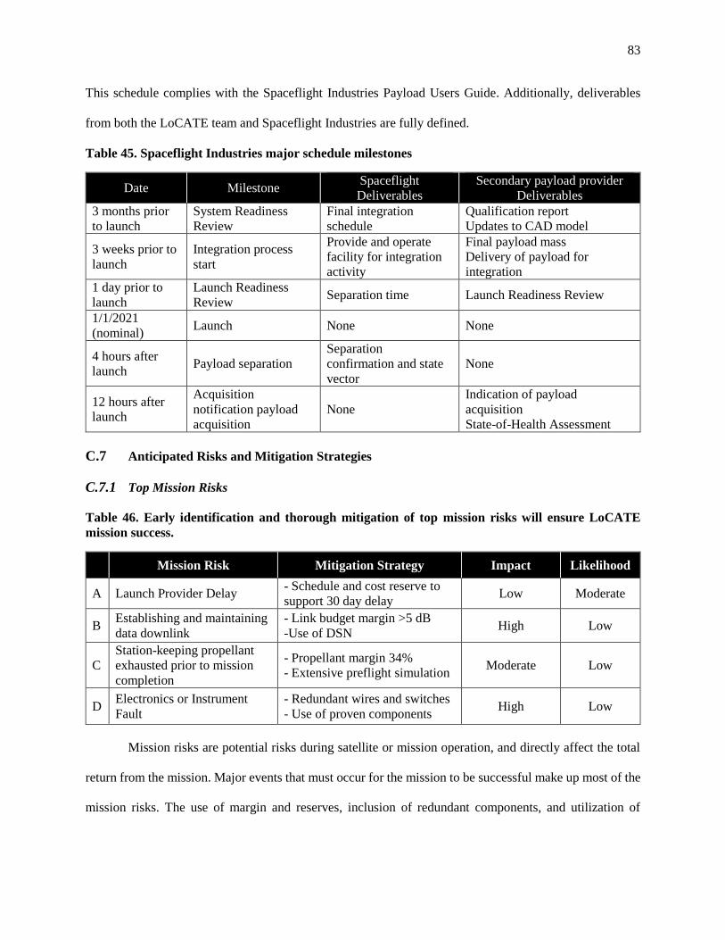
83
This schedule complies with the Spaceflight Industries Payload Users Guide. Additionally, deliverables
from both the LoCATE team and Spaceflight Industries are fully defined.
Table 45. Spaceflight Industries major schedule milestones
Date Milestone Spaceflight
Deliverables
Secondary payload provider
Deliverables
3 months prior
to launch
System Readiness
Review
Final integration
schedule
Qualification report
Updates to CAD model
3 weeks prior to
launch
Integration process
start
Provide and operate
facility for integration
activity
Final payload mass
Delivery of payload for
integration
1 day prior to
launch
Launch Readiness
Review Separation time Launch Readiness Review
1/1/2021
(nominal) Launch None None
4 hours after
launch Payload separation
Separation
confirmation and state
vector
None
12 hours after
launch
Acquisition
notification payload
acquisition
None
Indication of payload
acquisition
State-of-Health Assessment
C.7 Anticipated Risks and Mitigation Strategies
C.7.1 Top Mission Risks
Table 46. Early identification and thorough mitigation of top mission risks will ensure LoCATE
mission success.
Mission Risk Mitigation Strategy Impact Likelihood
A Launch Provider Delay - Schedule and cost reserve to
support 30 day delay Low Moderate
B Establishing and maintaining
data downlink
- Link budget margin >5 dB
-Use of DSN High Low
C
Station-keeping propellant
exhausted prior to mission
completion
- Propellant margin 34%
- Extensive preflight simulation Moderate Low
D Electronics or Instrument
Fault
- Redundant wires and switches
- Use of proven components High Low
Mission risks are potential risks during satellite or mission operation, and directly affect the total
return from the mission. Major events that must occur for the mission to be successful make up most of the
mission risks. The use of margin and reserves, inclusion of redundant components, and utilization of

84
extensive testing and simulation are a few of the techniques LoCATE uses to mitigate these top risks. The
top mission risk areas are identified in Table 46, along with their respective mitigation strategy.
LoCATE has chosen a medium-gain horn antenna which does not provide the same level of gains as a
traditional parabolic dish. Although this choice has provided significant savings in both cost and mass while
still satisfying mission requirements, it creates a risk by increasing the difficulty of establishing a data
downlink. The Deep Space Network (DSN) will be used as a relay point for communication between
LoCATE and Earth in order to take pressure off of the communications system. This array of satellites will
greatly decrease the probability of communication downlink failure. In addition, a significant link margin
of > 5 dB will be added to the link budget to enhance the spacecraft’s ability to communicate under
abnormal circumstances.
By choosing to launch as a secondary payload, the mission is at risk of having the launch delayed
by the third-party launch provider. A delay in launch would lead to increased costs regarding spacecraft
storage, as well as costs incurred due to retaining personnel for a longer time than scheduled. LoCATE
addresses this risk by dedicating schedule and cost reserves towards a potential launch delay. The third-
party launch provider has launch slots available for purchase up to two years in advance, so while a delay
is not expected, any issues with slot availability or launch date delays have been accounted for.
Since the target asteroid is too small to orbit, LoCATE will station-keep near the asteroid during
all mission operations following rendezvous. To accomplish this, LoCATE is equipped with a highly
efficient electric propulsion system which will also receive support from the reaction control system. These
systems are equipped with sufficient margins in order to ensure that the spacecraft is capable of station-
keeping long enough to complete the mission without risk of exhausting propellant. Furthermore, this
portion of the mission will undergo extensive trajectory simulation to confirm preparedness and improve
execution.

85
Mission risks are evaluated more in depth through a qualitative risk assessment. To accompany
Table 46, the top mission risks that have been identified are visually illustrated in a fever chart as shown in
Figure 22. By placing each risk in its appropriate location for likelihood
of occurrence and subsequent mission impact, the risks can be
characterized as low, medium, or high risks. The results of this study
conclude that LoCATE is a very low risk mission, as intended.
Risk mitigation is a vital part of mission development for
LoCATE. The techniques implemented thus far have eliminated or
substantially reduced the probability of both major and minor risks to
the project in both the implementation phase and the mission phase.
C.8 Cost and Cost Estimating Methodology
C.8.1 Cost Summary
The LoCATE mission cost model was defined with respect to clear science requirements, a detailed
science payload, and comprehensive implementation approach. Additionally, LoCATE implements
aggressive cost-saving strategies in accordance with the imposed cost limit of $100M. The mission utilizes
a small satellite architecture which reduces mass of total spacecraft and science payload. Consequently, the
proposed scientific instruments successfully complete mission goals while minimizing mass and cost.
LoCATE utilizes heritage and space-proven components in every subsystem to reduce cost risk. The
mission cost is $90.2M resulting in a 11% reserve. Table 47 shows the LoCATE cost by work breakdown
structure (WBS) element throughout all mission phases.
Figure 22. The LoCATE fever
chart indicates that top mission
risks are unlikely, with no
catastrophic impact.

86
Table 47. WBS Elements Across Mission Phases
WBS Element Phase A
$ (M)
Phase B
$ (M)
Phase C
$ (M)
Phase D
$ (M)
Phase E
$ (M)
Total
$ (M)
1.1 Spacecraft Bus 0.04 1.67 15.83 15.83 0.00 33.38
1.2 Payload 0.00 2.77 3.69 3.69 0.00 10.15
1.3 Spacecraft/Payload IA&T 0.00 0.00 2.52 2.52 0.00 5.04
2.0 Launch Vehicle 0.00 0.48 4.76 4.76 0.00 10.00
3.0 Ground Control &
Command 0.00 0.00 0.00 1.92 8.79 10.70
4.1 Systems Engineering 0.00 0.25 0.64 0.64 0.08 1.62
4.2 Program Management 0.08 0.36 0.61 0.61 0.14 1.80
4.3 System Integration and Test 0.00 0.00 0.45 0.45 0.00 0.90
4.4 Project Mission Assurance 0.00 0.03 0.07 0.07 0.01 0.18
4.5 Assorted Program Level
Wrap Factors 0.00 0.10 0.76 0.76 0.83 2.45
5.0 Flight Support Operations
& Services 0.04 0.18 0.31 0.31 0.71 1.55
6.0 Aerospace Ground
Equipment 0.00 0.00 0.34 0.34 1.01 1.68
7.0 Operations 0.00 0.40 2.00 2.00 6.36 10.77
Total Mission Cost 0.16 6.24 31.98 33.90 17.92 90.20
Reserve % 11%
C.8.2 Cost Estimating Methodology
A comprehensive and credible cost estimate model was formed by combining parametric and analogous
estimating techniques. Analogy estimates are based on historical data and are a quick and readily
understood method of early cost estimates.56 Missions analogous to LoCATE include NEAR Shoemaker,
DAWN, and Deep Space I. LoCATE is somewhat different than these missions however, due to its
particularly low cost and smaller size. These constraints allow analogous comparisons of larger missions
to be applied to LoCATE while maintaining appropriate margin.

87
Table 48. LoCATE Complete Cost Model includes all WBS elements.
WBS # WBS Element Cost Driver Value Cost
FY2016
[$K]
1.1.1 Structure Structure Weight (kg) 24.7 $2,170
1.1.2 Thermal Control Thermal Weight (kg) 11.7 $1,243
1.1.3 ADACS ADCS Dry Weight (kg) 15.0 $5,035
1.1.4 EPS EPS Weight (kg) 15.4 $5,733
1.1.5 Propulsion (Reaction Control) Spacecraft Bus Dry Weight (kg) 124.2 $1,568
1.1.6a Telemetry, Tracking, and
Command (TT&C) TT&C Weight (kg) 3 $818
1.1.6b Command and Data Handling
(CD&H)
Command and Data Handling
Weight (kg) 3 $1,106
1.1.7 Integration, Assembly, and Test
(IA&T) Estimated ($K) N/A $5,000
1.2 Payload Spacecraft Bus Total Cost ($K) 22673.3 $10,150
1.3 Spacecraft/Payload IA&T Spacecraft Bus Total ($K) 22673.3 $3,527
4.0 Program Level Sum 4.1-4.5 N/A $8,460
4.1 Systems Engineering Wrap Factor (%) 0.18 $1,620
4.2 Project Management Wrap Factor (%) 0.20 $1,800
4.3 System Integration and Test
(I&T) Wrap Factor (%) 0.10 $900
4.4 Product Assurance Wrap Factor (%) 0.02 $180
4.5 Configuration Management Wrap Factor (%) 0.03 $270
4.5 Contractor (or subcontractor) Fee Wrap Factor (%) 0.12 $1,080
4.5 Data Management Wrap Factor (%) 0.02 $180
4.5 Development Support Facility Wrap Factor (%) 0.03 $270
4.5 Hardware/Software Integration Wrap Factor (%) 0.12 $1,080
4.5 Integrated Logistics Wrap Factor (%) 0.04 $360
4.5 Safety & Misison Assurance Wrap Factor (%) 0.07 $630
4.5 Site Activation Wrap Factor (%) 0.01 $90
5.0 Flight Support Operations &
Services Spacecraft Bus Total Cost ($K) 22673 $1,548
6.0 Aerospace Ground Equipment
(AGE) Spacecraft Bus Total Cost ($K) 22673 $1,675
2.0 Launch Vehicle Spaceflight Industries Quoted
Value $10,000
1.1.8/3.0 Ground Command Control and
Software SLOC 22500 $21,404
7.0 Operations Mission Operations Cost
Prediction Model $10,767
7.1 PMSE (annual) Space and Ground Segment CER $566
7.2 Space (annual) Software SLOC and Engineer
FTE $200
7.2 Ground (annual) Facilities/Hardware/Manpower
CER $3,576
Total
Total Mission Cost $90,204
Reserve 11%

88
Parametric cost models use statistical relationships with diverse inputs that rely on logical
correlation and thorough research.56 The first parametric model applied to the LoCATE mission is the small
spacecraft cost model (SSCM). SSCM includes extensive cost estimating relationships (CERs) that outline
costs for most elements in the WBS with the notable exceptions of launch vehicle, ground command and
control, and operations.26 Cost estimates for these WBS elements were calculated from other CERs and
quoted values. The complete cost model for LoCATE is detailed in Table 48.
Table 49. Operational Budget Inputs.
Assumptions Value Units
Software for Space 16,000 SLOC
Software for Ground 4,000 SLOC
Hardware Acquisition Cost 1,400 $K
% of Hardware Acquisition for Ground Hardware
Maintenance 7%
Facility Lease 1,000 m2
$/sq meter 1.25 K/m2
% of Operations Cost for PMSM (10% - 20%) 15%
FTE Overhead Adjustment (excluding admin, contractor,
travel) 150%
Number of Engineers for Mission Ops 12
Engineer Annual Salary 80 $K
Engineer FTE 200 $K
Number of Technicians for Mission Ops 6
Technician Salary 60 $K
Technician FTE 150 $K
Number of Years of Operation 1.92
Operational costs were found using the Mission Operations Cost Prediction Model.26 The CERs in
this model use inputs of software for space and ground, hardware acquisition cost, facility lease and square
mileage, FTE overhead, engineer number and salary, technician number and salary, and years of operation
to output operational costs in labor and facility use. Software lines of code (SLOC) values were found by

89
analogous comparison to similar sized missions. Using SLOCs as a metric in costing estimates has been
debated within the community due to an unclear definition of SLOC and the increasing complexity available
in software. Therefore, margin was included within the operational budget.57 Table 49 and Table 50 show
appropriate inputs, CERs, and outputs for the operational budget.
Table 50. Operational Budget Outputs.
SME-SMAD WBS Element 7.0 Operations Cost Category Annual Cost ($K)
PMSE Labor 731
Space Segment Software Maintenance Labor 200
Ground Segment 4,676
Mission Operations Labor 3,300
Ground Segment Software Maintenance Labor 28
Ground Hardware Maintenance Labor 98
Facilities Facility Lease 1,250
Total Annual Operations Phase Cost 5,608
Total Mission Operations Cost 10,767
Program level costs including systems engineering, program management, system integration and
test, and product assurance were calculated by combing parametric models from SSCM and applying cost
factor percentages to calculate wrap factors. The parametric model uses a CER that takes the spacecraft bus
cost as an input and outputs a program level cost of $5.8M. Alternatively, cost factor percentages were used
to calculate program level wrap factors which resulted in program level costs of $12.8M.26 Combining the
fact that LoCATE has a constrained size and cost with program level costs from analogous missions, the
program level cost was determined to be $8.5M.
Spaceflight Industries is a reliable private aerospace company that specializes in the launch of
secondary payloads who have successfully integrated 77 satellites as secondary payloads to date. Table 51
lists the secondary payload launch costs for various satellite weights going to various orbits. This table is
quoted directly from the Spaceflight Industries, Inc. website.54 Cost increases with mass as expected and

90
also increases from LEO to GTO to GEO/GSO. Cost and mass were the driving factors when choosing the
orbit. A LEO orbit would be cost effective but at the cost of having a heavier and more complex booster
stage to achieve Earth escape. Launch to GEO/GSO requires significantly higher cost and would still
require a booster stage for Earth escape. The best compromise between these options is the cost-effective
GTO orbit.
Table 51. Spaceflight Industries provides cost-effective launch opportunities to for small satellites.
Costs are in thousands of dollars.
The quoted value for a secondary launch opportunity of a 300 kg satellite to GTO is $9.95M. Spaceflight
Industries also provides a standard payment structure listed in Table 52. This payment structure can be
easily followed in accordance with the mission phase costs shown in Table 47.
Table 52. Spaceflight Industries Standard Payment Structure.
% of Launch Cost Amount Due [$K] Date Due
10% $1,000 Launch Reservation Down Payment
30% $3,000 Launch minus 24 months
20% $2,000 Launch minus 19 months
20% $2,000 Launch minus 13 months
15% $1,500 Launch minus 7 months
5% $500 Launch (1/1/2022)

91
C.8.3 Validity of Cost Estimates
The SSCM model uses CERs based on 53 satellites from the past 2 decades to estimate cost for
earth orbiting missions under 500 kg. Because, the LoCATE mission does not remain in LEO, the SSCM
model was used as a first order estimate of cost, with reserve held for the additional expense of planetary
missions. The SSCM Model is shown in Table 53. This model excludes WBS 2.0, 3.0, and 7.0. However,
when compared to the appropriate WBS elements in the complete cost model, it attains a percent difference
of 9.8%.
Table 53. SSCM Model for LoCATE.
An additional cost-estimating tool utilized is the QuickCost model. This simplified model uses 10
inputs ranging from dry mass to team experience, to output a cost estimate. The QuickCost model for the
LoCATE mission is detailed in Table 54.
Lower Limit Value* Upper Limit 2016
1.1.1 Structure Structure Weight (kg) 5 24.7 100 $1,939 $1,097 $2,170
1.1.2 Thermal Control Thermal Weight (kg) 5 13.5 12 $1,380 $119 $1,544
1.1.3
Attitude Determination and Control
System (ADCS) ADCS Dry Weight (kg) 1 14.5 25 $4,318 $1,113 $4,832
1.1.4 Electrical Power System (EPS) EPS Weight (kg) 7 15.4 70 $5,123 $910 $5,733
1.1.5 Propulsion (Reaction Control)
Spacecraft Bus Dry
Weight (kg) 20 124.2 400 $1,401 $310 $1,568
1.1.6a
Telemetry, Tracking, and Command
(TT&C) TT&C Weight (kg) 3 3 30 $731 $629 $818
1.1.6b Command and Data Handling (CD&H)
Command and Data
Handling Weight (kg) 3 3 30 $989 $854 $1,106
1.2 Payload
Spacecraft Bus Total
Cost ($K) 2,600 17,772 69,000 $7,109 Not Given $7,956
1.3 Integration, Assemby, and Test (IA&T)
Spacecraft Bus Total
Cost ($K) 2,600 17,772 69,000 $2,470 Not Given $2,765
4.0 Program Level
Spacecraft Bus Total
Cost ($K) 2,600 17,772 69,000 $4,070 Not Given $4,555
5.0
Launch and Orbital Operations Support
(LOOS)
Spacecraft Bus Total
Cost ($K) 2,600 17,772 69,000 $1,084 Not Given $1,213
6.0 Aerospace Ground Equipment (AGE)
Spacecraft Bus Total
Cost ($K) 2,600 17,772 69,000 $1,173 Not Given $1,313
All Subsystems $46,995 $52,595
Total
N/A
SME-SMAD WBS ElementWBS #
Spacecraft
Payload
Spacecraft Integration, Assembly, and Test
Program Level
Flight Support
Aerospace Ground Equipment (AGE)
Cost Driver(s)
Estimatined
Cost in
FY2010 [$K]
Absolute
Standard Error
of the Estimate
(SEE) FY2010 $
Estimated
Cost in $K for
Fiscal Year:
Cost Driver
Input a value between the Lower Limit
and Upper Limit in the Value Column

92
Table 54. The QuickCost model proves small planetary missions are affordable.
The QuickCost model specifically accounts for planetary vs. LEO missions as can be seen in Table
54. This model verifies that the LoCATE mission remains cost feasible while being a planetary mission.
Being a simplified model, the QuickCost accounts for only the space vehicle (WBS 1.0) with an estimated
cost of $45 M and an SEE of 41.0%. The space vehicle cost from the complete cost model is $48.1 M,
which confirms these estimates.
2016
Space Vehicle for Unmanned Robotic Mission $41 41.0% $45
Dry Mass (kg) of spacecraft bus and instruments 76 124 14,475
Power (W) of LEO equivalent beginning of life power (BOLP) 90 1,212 10,000
Data Rate Percentile (%) relative to the state-of-the-art at
Authority to proceed (ATP) 0% 50% 100%
Advertised Design Life (months) excluding extended
operations6 24 180
Percentage of New (%) [enter 20%-30% for Simple Mod, 30%-
70% for Extensive Mod, 70%-100% for New Technology28% 28% 130%
Planetary? [YES/NO] Input 0 for NO 1 Input 1 for YES
ATP Years [YEAR minus 1960] 1961 2016 2005Instrument Complexity Percentile (%) relative to "average"
instrument complexity0% 10% 100%
Team Experience [enter 1 for Unfamiliar, 2 for Mixed, 3 for
Normal, 4 for Extensive]1 3 4
SME-SMAD WBS Element
Estimatined
Cost in FY2010
[$M]
Absolute
Standard Error of
the Estimate
(SEE) [%]
Estimated Cost in
$M for Fiscal Year:
Upper LimitValueLower LimitCost Driver

93
D References
1AIAA, "Low-Cost Asteroid Precursor Mission - Request for Proposal," AIAA, 2015. 2Z. R. Putnam, "Low-Cost Asteroid Precursor Mission Request for Proposal Addendum," Urbana, IL, 2016. 3A. Siddiqi, Challenge to Apollo: The Soviet Union and the Space Race 1945-1974, Washington D.C.:
NASA History Division, Library of Congress, 2000. 4J. B. Hopkins and A. F. Dissel, "Plymouth Rock: Early Human Missions to Near Earth Asteroids Using
Orion Spacecraft," Lockheed Martin, 2010. 5M. Gates, "Asteroid Redirect Mission (ARM) Status," NASA Headquarters, Washington D.C., 2016. 6P. Chodas, "Near Earth Object Program," NASA, 02 March 2016. [Online]. Available:
http://neo.jpl.nasa.gov/stats/. [Accessed February 2016]. 7R. P. Binzel and S. J. Bus, "Phase II of the Small Main-Belt Asteroid Spectroscopic Survey. A Feature-
Based Taxonomy," Icarus, vol. 158, no. 1, pp. 146-177, 2002. 8M. T. De Sanctis, M. C. Coradini, E. Capria, S. Ammannito, G. Filacchione, G. Fonte, A. Magni, I. Bini
and F. Veltroni, "VIR-Visual Infrared Mapping Spectrometer of Dawn Mission," Lunar and Planetary Science,
2008. 9M. C. De Sanctis, A. Coradini, E. Ammannito, M. T. Capria and S. Fonte, "VIR, the imaging spectrometer
for the asteroid belt exploration," Italian Society of Astronautics, 2009. 10"Gravity Mapping: Measuring Mass Concentration," NASA. 11"Seeking a Human Spaceflight Program Worthy of a Great Nation," Review of U.S. Human Spaceflight
Plans Committee, 2009. 12D. C. Hovde, M. D. Prouty, I. Hrvoic and R. E. Slocum, "Commercial magnetometers and their
application," in Optical Magnetometry, Cambridge University Press, 2013, pp. 387-405. 13"Dawn Framing Camera Instrument Information," NASA PDS: The Planetary Data System, March 2016.
[Online]. Available: https://pds.nasa.gov/ds-
view/pds/viewInstrumentProfile.jsp?INSTRUMENT_ID=FC2&INSTRUMENT_HOST_ID=DAWN. [Accessed
April 2016]. 14"Dawn Visible and Infrared Spectrometer Instrument Information," NASA PDS: The Planetary Data
System, March 2016. [Online]. Available: https://pds.nasa.gov/ds-
view/pds/viewInstrumentProfile.jsp?INSTRUMENT_ID=VIR&INSTRUMENT_HOST_ID=DAWN. [Accessed
April 2016]. 15"Micro Dosimeter," Teledyne Microelectronic Technologies, Lewisburg, 2015. 16"Magnetometer," Surrey Satellite Technology Ltd, Surrey, 2014. 17Alliant Techsystems Inc., "ATK Space Propulsion Products Catalog," Alliant TechSystems Inc., Elkton,
MD, 2008. 18Busek Space Propulsion and Systems, "Busek RF Ion Thrusters," Busek CO, Inc., 2013, 2013. 19G. Lawrence, S. Reid, M. Kruglanski and N. Parmentier, "Space Environmet Information System -
SPENVIS: Applicability for Mission Operations," in American Geophysical Union Fall Meeting, San Francisco,
2009. 20B. W. Barbee, "Accessible Near-Earth Objects (NEOs)," NASA/GSFC, Greenbelt, MA, 2015. 21J. Englander, Automated Trajectory Planning for Multiple-Flyby Interplanetary Missions, Urbana, IL:
University of Illinois at Urbana Champaign, 2013. 22F. De Pasquale, Interviewee, Briefing at Guiana Space Center. [Interview]. 23 January 2012. 23M. o. D. source, Interviewee, Interview. [Interview]. 10 November 2005. 24J. Buck and G. H. Diller, "CONTRACT RELEASE C14-047," Washington D.C., 2014. 25Advanced Technical Materials Inc., "Standard and High Gain Horn Antenna For RF Microwave," 2016. 26J. R. Wertz and D. F. P. J. J. Everett, Space Mission Engineering: The New SMAD, Hawthorne, MA:
Microcosm Press, 2011. 27Moog Bradford, "Mini Fine Sun Sensor," Heerle, 2014. 28Space Micro, "Miniature Integrated Star Tracker (MIST)," San Diego, CA, 2015. 29Airbus Defence and Space, "Space Propulsion Chemical Monopropellant Thrust Family - 1N, 20N, 400N
and Heritage Thruster". 30Moog, Inc, "VC03 Fill and Drain Valve," Gloucestershire, 2013. 31VACCO Space Products, "1/4" High Pressure Latch Valve," South El Monte, 2004. 32Taber Industries, "Taber Industries Program Transducers," 2015.

94
33VACCO Space Products, "1/2" High Flow Filter Assembly F1d10639-01," South El Monte, CA, 2004. 34Space Micro, "Proton2X-Box Suite," 2015. 35Antenna Development Corporation, "Microstrip Patch Antennas," Las Cruces, New Mexico, 2013. 36Thales Alenia Space France, "8PSK X-Band Transmitter," 2012. 37General Dynamics - Advanced Information Systems, "Small Deep-Space Transponder (SDST)". 38Thales, "X-band space Traveling Wave Tubes". 39Jet Propulsion Laboratory, "DSN Telecommunications Link Design Handbook (810-005)," 2015. 40K. McCarthy and D. Carter, "Near Earth Network (NEN) Users' Guide," Greenbelt, MD, 2015. 41Aerojet, "Monopropellant Data Sheets," Redmond, WA, 2008. 42Aerojet, "Bipropellant Data Sheets," 2009. [Online]. [Accessed February 2009]. 43ATK, "ATK Part Number 80421-1," Alliant Techsystems Inc., Commerce, California. 44Airbus Defense & Space, "PPU for Electric Propulsion," Airbus Defense and Space SAS, 2014. 45Busek Advance Space Propulsion, "Hollow Cathodes," Busek Co. Inc., Natick, MA, 2012. 46Busek Space Propulsion and Systems, "BHT-200 Hall Thruster," Busek Co, Inc, Natick, MA, 2015. 47Busek Space Propulsion and Systems, "BHT-600 Busek Hall Effect Thruster," Busek Co. Inc., Natick,
MA, 2016. 48Busek Co., "Busek Low Power Hall Thrusters," Busek Co., Natick, MA, 2013. 49S. Y.-M. Cheng, "Modeling of Hall Thruster Lifetime and Erosion Mechanisms," Massachussetts Institute
of Technology, Cambridge, MA, 2007. 50D. M. Bui, "Plume Characterization of Busek 600W Hall Thruster," Air Force Institute of Technology,
Dayton, OH, 2012. 51Measurement Specialties, "ESCC Epoxy Coated Thermistors," 2008. 52Thermacore Inc., "k-Core Radiator Panels - Ensuring Performance in Space," 2016. [Online]. Available:
http://www.thermacore.com/products/radiator-panels.aspx. [Accessed 19 April 2016]. 53National Plastic Heater, "Kapton/Silicone Rubber Flexible Heaters," Schomberg, Ontario Canada. 54Spaceflight, Inc, "Spaceflight, Inc. General Payload Users Guide," Tukwila, WA, 2016. 55M. E. Holdridge, "NEAR Shoemaker Spacecraft Mission Operations," Johns Hopkins APL Technical
Digest, pp. p. 58-70, 2002. 56National Aeronautics and Space Administration, "NASA Cost Estimating Handbook Version 54.0," 2015. 57N. Krepps, "Analysis of Recent NASA Flight Software Costs," Johns Hopkins University Applied
Physics Laboratory, Laurel, MD, 2015.

95
E Proposal Acronyms/Abbreviations
ADACS Attitude Determination and Control System
AGE Aerospace Ground Equipment
ARCM Asteroid Redirect Crewed Mission
ARM Asteroid Redirect Mission
ATCS Active Thermal Control System
ATLO Assembly, Test, and Launch Operations
BER Bit Error Rate
BPSK Binary Phase Shift Keying
BWG Beam Waveguide
C&DH Command and Data Handling
CER Cost Estimating Relationship
DSN Deep Space Network
Eb Energy per Bit
EIRP Effective Isotropic Radiated Power
EPS Electric Propulsion System
FEC Forward Error Correction
FTE Full-time Equivalent
GaAs Gallium Arsenide
GTO Geostationary Transfer Orbit
HEF High Efficiency
I&T Integration and Test
IA&T Integration, Assembly, and Test
ISP
ISRU
Specific Impulse
In-Situ Resource Utilization
LEO Low-Earth Orbit
LoCATE Low-Cost Asteroid Topographical Explorer
ME Main Electronics
MLI Multilayer Insulation
MPS Max Planck Institute for Solar System Research
NEA Near Earth Asteroids
NEN Naer Earth Network
NHATS Near-Earth Object Human Spac Flight Accessible Targets Study
OM Optics Module
PEM Proximity Electronics Module
PI Principal Investigator
PM Program Manager
PMSE Programme Making and Special Events
PPT Peak Power Tracker
PTCS Passive Thermal Control System

96
QPSK Quadrature Phase Shift Keying
RPI Radial Port Interface
SLOC Source Lines of Code
SMASS Small Main-Belt Asteroid Spectroscopic Survey
SPENVIS Space Environment Information System
SSCM Small Spacecraft Costing Model
STM Science Traceability Matrix
TID Total Ionizing Dose
TRL Technology Readiness Level
TT&C Telemetry, Tracking, and Command
VIMS-V Visible Infrared Spectrometer
VIR Visual and Infrared
VIRTIS Visible Infrared Thermal Imaging Spectrometer
WBS Work Breakdown Statement