logic pro - d2zjg0qo565n2.cloudfront.net every case it will be necessary to ... avid and pro tools...
TRANSCRIPT

Logic ProAutomation & Control Surface Manual
Version: 1.4

WarrantyAll Focusrite products are built to the highest standards and should provide reliable performance for many years, subject to reasonable care, use, transportation and storage.In the event of a Manufacturing Defect becoming evident within 12 months from date of purchase Focusrite undertakes that the product will be repaired or replaced free of charge if the product is returned to the authorised dealer from whom it was purchased. In these circumstances, or if you need an out-of-warranty repair to your Focusrite product, please contact your local Focusrite distributor in your country of residence or business. Find your local distributor and you will be advised of the correct return procedure. Alternatively contact the Focusrite Reseller from which you purchased the product. If you purchase a Focusrite product outside your country of residence or business you will not be entitled to ask your local Focusrite distributor to honour this Limited Warranty, although you may request a chargeable repair.Alternatively, the unit may be returned at your cost to the dealer you purchased the unit from so that they can organise a Warranty repair with their Focusrite distributor. This Warranty does not include cost of shipping to and from the authorised dealer from whom it was purchased. In every case it will be necessary to provide the original invoice or store receipt to accompany the defective product to the supplying dealer.This Limited Warranty is offered solely to the first purchaser of the product from an Authorised Focusrite Reseller (defined as a reseller which has purchased the Product directly from Focusrite Audio Engineering Limited in the UK or its Authorised Distributors outside the U.K.) and is not transferable. This Warranty is in addition to your Statutory Rights in the country of purchase.Please note: A Manufacturing Defect is defined as a defect in the performance of the product which may be expected from a reasonable interpretation of the published description and performance specifications as published by Focusrite Audio Engineering Limited. This does not include damage caused by post-purchase transportation, storage or careless handling, nor damage caused by misuse. A significant proportion of products returned under Warranty (which are very few in number compared to numbers sold) are found not to exhibit any fault at all. Please check that the mains voltage is correctly set for your local supply and that your connecting cables are in good order and correctly connected. If in doubt about the product functions please read the appropriate section of the user guide, and if necessary contact your dealer for advice before returning the product to the supplying dealer. You can also contact the Focusrite Technical support team should you require further assistance.
AccuracyWhilst every effort has been made to ensure the accuracy and completeness of the content of this manual, Focusrite Audio Engineering Limited makes no representation or warranty as to the accuracy, completeness or reasonableness of the content and no such representation or warranty is implied.
Trade MarksAlps is a registered trade mark of Alps Electric Co. Ltd.Apple, Logic and Mac are trade marks of Apple Inc. registered in the U.S. and other countriesAvid and Pro Tools are registered trade marks of Avid Technology Inc. or its subsidiaries in the U.S. and/or other countriesMackie is a registered trade mark and HUI is trade mark of LOUD Technologies Inc.Prism Sound is a registered trade mark of Prism Media Products Ltd.Steinberg, Cubase and Nuendo are registered trade marks of Steinberg Media Technologies GmbH.Tascam is a trade mark of TEAC Corporation, registered in the U.S. and other countriesWindows and Windows XP are trade marks of Microsoft Corporation registered in the U.S. and other countries
All other products, trade marks and trade names are the property of their respective owners.
CopyrightCopyright © 2012 Focusrite Audio Engineering Limited. All rights reserved. Any reproduction or transmission of all or part of this manual, whether by photocopying or storing in any medium by electronic means or otherwise, without written permission of the owner, is prohibited.This manual and the information set out in this manual the exclusive property of Focusrite Audio Engineering Limited.

About this Manual
Control 2802 Logic Pro Automation & Control Surface Manual 3
About this ManualBy connecting Control 2802 to your DAW computer via Ethernet, and configuring the DAW software to support Control 2802 as a HUITM control surface, the console supports two major features: a DAW control surface layer and analogue fader automation.
This manual covers the setup and operation of these features when connecting to Logic Pro. Note that separate versions of this manual exist for each of the major DAWs: ProTools, Logic Pro and Cubase.
You should already be familiar with console operation. If not, please read the “Control 2802 Operating Manual”. All the documentation is included on the CD packed with the console, or may be downloaded from our website at: www.focusrite.com
About this Manual & Contents
ContentsAbout this Manual 3
Control Surface (DAW Control) Overview 4Dual Layer Fader Strips 4Control Surface Panel 4
Analogue Fader Automation Overview 5
Network Connections & Setup (Mac) 6DAW Ethernet Connection (Mac) 6Network Configuration (Mac) 6
Control Surface Configuration 8
Control Surface Operation 11Starting the Software 11Layer Switching 11Working in the DAW Layer - First Steps 11Control Surface Panel 12Accessing Tracks and Parameters 13Transport Panel 13Navigation & Utility Controls 14DAW Meters (17) 17Function Keys 24Console SETUP 24
Analogue Fader & CUT Automation 25Preparing for Analogue Automation 26Writing and Replaying Analogue Automation 26
Automation - Tips and Suggestions 27Automation Modes in Logic 27Writing and Viewing Automation in Logic 27Hiding Tracks in Logic 27
Future Updates 28
Panel Visualisation 29

4 Control 2802 Logic Pro Automation & Control Surface Manual
Control Surface (DAW Control) Overview
Control Surface (DAW Control) OverviewDual Layer Fader StripsThe 8 Fader Strips (faders, SEL, CUT & SOLO) flip between controlling analogue channel levels and track faders within the DAW. This dual-layer technology makes it easy to switch from analogue to DAW control in an instant.When working in the DAW layer, the console remotely adjusts parameters within the DAW software via an Ethernet connection (using the HUITM control surface protocol). Any 8 DAW tracks may be adjusted from the console’s Fader Strips.Each of the 8 channel faders is motorised, and both the analogue and DAW layers can be fully automated.
Control Surface PanelThe layer switching, and other DAW parameters, such as auxes, plug-ins, transport and automation, are controlled from Control Surface Centre Section - this includes a jog/shuttle wheel, transport buttons, 4 rotary encoders and OLED channel displays.

Analogue Fader Automation Overview
Control 2802 Logic Pro Automation & Control Surface Manual 5
Analogue Fader Automation OverviewHUITM / MIDI automation from your DAW can be applied to Control 2802’s analogue channel levels and motorised faders. This allows you to automate the faders and CUTs of the 8 analogue main channel paths.This feature works by setting up 8 “dummy” audio channels in your DAW - blank channels that contain no audio. Then using these to write and replay automation to the 8 analogue faders and CUTs of Control 2802. By running the “dummy” channels along with the rest of your DAW mix, you can replay automation on both the analogue channel levels and DAW tracks simultaneously - use the DAW switch (on the Control Surface Panel) to flip between the analogue and DAW fader layers.The diagram below provides an overview of the analogue automation system and the parameters that can be controlled:
To use either the DAW control surface layer or analogue fader automation, you must connect Control 2802 to your DAW computer via Ethernet, and configure the DAW software to support Control 2802 as a HUITM control surface. The next few pages describe the setup in detail:
● Network Connection & Setup - page 6. ● Control Surface Conifiguration in Logic Pro - page 8.

6 Control 2802 Logic Pro Automation & Control Surface Manual
Network Connections & Setup (Mac)
Network Connections & Setup (Mac)DAW Ethernet Connection (Mac)Use the rear panel NETWORK port to connect Control 2802 to your studio DAW computer, via a standard RJ-45 CAT-5e Ethernet cable. The interface in Control 2802 is compatible whether you use a straight or cross-over cable. There are two LEDs beside the NETWORK port that indicate network connection and activity.
Then download and install the latest version of the Control 2802.dmg application from our wesbite at www.focusrite.comOn Apple computers, add the software to your applications folder (Macintosh HD > Applications) via drag and drop.If you wish, you can enable the application to always boot upon user log-in. Select ‘System Preferences... > Accounts > (select the user account you wish to alter) > Login Items tab > Add Item (+ button)’. Browse and select Focusrite Control 2802:
Everytime this user account opens, Focusrite Control 2802 should now boot.
Network Configuration (Mac)Once you have connected Control 2802 to your computer and installed the software, you are ready to set up the networking side of the console.
IP Address Setup for Direct ConnectionIf you have a direct Ethernet connection between Control 2802 and your DAW computer, first you must set up your DAW IP address.Please note that if you have a router, then the IP address should not be adjusted and you should skip to “Setting up the console with DHCP (for use with routers)” on page 7.To set the DAW IP address:Select ‘System Preferences... > Network > Ethernet > Location > Edit Locations... > Add New Location (+ button)’ and name the location as Control 2802. Select this Location and enter the following settings:
● ‘Configure’ to Manually ● ‘IP Address’ to 192.168.0.1 ● ‘Subnet Mask’ to 255.255.255.0
Click to Apply to confirm the settings; the status should update to show that the Ethernet port is Connected.
Move across to the Control 2802, power up the console and once booted, press the SETUP switch.
The OLED displays will show the first page of console setup:
Use the first rotary encoder to select the DAW application you are using with Control 2802.The options at the time of release include:
● Apple Logic Pro 9 ● Avid Pro Tools 8 ● Steinberg Cubase 5 (Nuendo)
Once a change has been made, the setup switch LED will flash to indicate that a setting has changed.If you exit setup by pressing the switch once more, and then return by entering setup again, your setting
is saved automatically.
Using the PAGE keys (below the first rotary encoder), page to the right and ensure that Use DHCP is set to NO.

Network Connections & Setup (Mac)
Control 2802 Logic Pro Automation & Control Surface Manual 7
Page right again to reach the IP address screen and set the IP address to 192.168.0.100 (default) using the encoders:
Then move to the fourth page, and check that the subnet mask is set to 255.255.255.0:
Page right again and check that the port is set to 1212:
Press the setup key to exit setup and your setting will be saved.
Now power down the console and restart your Apple computer.Once booted, ensure that the Focusrite Control 2802 application is open on your DAW computer. Finally power up the console.After the console boots, it should be detected by the software and show its serial number:
You may have to repeat the power down / restart process if you are experiencing difficulties.Select the console and click on Connect (bottom right).Your console is now connected to the DAW computer and ready for HUITM control surface configuration, see page 8.
Note that if you close the ‘Focusrite Control 2802’ window, the software continues to run in the background. If you wish to quit the application, select Quit from the main menu.
Setting up the console with DHCP (for use with routers)If you have connected Control 2802 to your DAW computer via a network router, you will need to use DHCP to enable automatic configuration of IP address.Ensure that you enable DHCP in your DAW computer’s ‘System Preferences’:
And that the console is set to use DHCP on the second page of the setup menu:
Then reboot the console. Once the console is detected, follow the same connection procedure as described earlier.
8 Control 2802 Logic Pro Automation & Control Surface Manual
Control Surface Configuration
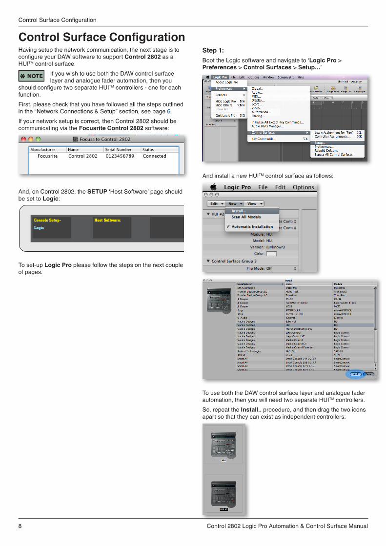
Control Surface ConfigurationHaving setup the network communication, the next stage is to configure your DAW software to support Control 2802 as a HUITM control surface.
If you wish to use both the DAW control surface layer and analogue fader automation, then you
should configure two separate HUITM controllers - one for each function.First, please check that you have followed all the steps outlined in the “Network Connections & Setup” section, see page 6.If your network setup is correct, then Control 2802 should be communicating via the Focusrite Control 2802 software:
And, on Control 2802, the SETUP ‘Host Software’ page should be set to Logic:
To set-up Logic Pro please follow the steps on the next couple of pages.
Step 1:Boot the Logic software and navigate to ‘Logic Pro > Preferences > Control Surfaces > Setup…’
And install a new HUITM control surface as follows:
To use both the DAW control surface layer and analogue fader automation, then you will need two separate HUITM controllers. So, repeat the Install.. procedure, and then drag the two icons apart so that they can exist as independent controllers:

Control Surface Configuration
Control 2802 Logic Pro Automation & Control Surface Manual 9
Step 2: Define the function of the HUITM control surface by assigning its input and output MIDI ports. These can be accessed by selecting a HUITM control surface, and then clicking on the drop-down ‘Output Port’ and ‘Input Port’ menus:
If you are using two separate HUITM controllers, then HUI 1 should be set to Automation and HUI 2 to Control surface as follows:Select the first HUITM control surface and set both the ‘Output Port’ and ‘Input Port’ to Control 2802 - Automation:
Then select HUI #2 and set both the ‘Output Port’ and ‘Input Port’ to Control 2802 - Control Surface:
On the first HUITM control surface (assigned to Automation), you might also want to lock the ‘Channel Strip View Mode’ to Tracks only:
This alows you to hide these tracks, using Logic’s Hide function, to keep your session tidy. See page 27 for details.

10 Control 2802 Logic Pro Automation & Control Surface Manual
Control Surface Configuration
Step 3:Close the control surface ‘Setup’ window (top left) and navigate to: ‘Logic Pro > Preferences > Control Surfaces > Preferences…’
Please set the following parameters to ensure smooth operation of the control surface:a. Set the Resolution of Relative Controls to 1024 (or any
value greater than 512).b. Set the Maximum MIDI Bandwidth to 100%.c. De-select Control surface follows track selection. d. You can also de-select touching fader selects track if that
improves your workflow within Logic.
Close the control surface ‘Preferences’ window (top left). If you have only one HUITM controller, configured for Control Surface operation, then the setup is complete and you can skip to page 11 for details on operation.If you have installed a second HUITM controller, configured for Automation, then continue to step 4.
Step 4 (for Analogue Fader Automation only)Return to the ‘Arrange’ window and create 8 mono “dummy” audio tracks - these will be used to write and replay fader and CUT automation on the 8 analogue channels of Control 2802.
We recommend that you de-assign any input and output track routing. This prevents you from
recording audio, making it easier to see that these are automation-only tracks. You can do this by using the Input and Output assign boxes, in the ‘New Tracks’ dialogue window, when creating the tracks:
Then click and drag the 8 tracks to the top of the ‘Arrange’ window so that they are the first 8 tracks - the first 8 tracks in the Logic session are always used to write and replay automation to the analogue layer.The “dummy” automation tracks are indicated by a white marker in the track header (this is the default colour, but it can be changed from the Color field during step 2):
We also recommend renaming the track labels to make it easier to see that these are automation-
only tracks - for example, AUTO1, AUTO2, AUTO3, etc. Perhaps with a further addition of the source you are riding - AUTO1-LDVox, AUTO2-Gtr, AUTO3-DrumsL, etc.The setup for the Automation HUITM controller is now complete. Please see page 27 for details on how to write and replay analogue layer automation.

Control Surface Operation
Control 2802 Logic Pro Automation & Control Surface Manual 11
Control Surface OperationStarting the Software
If you have shut down your computer since setting up the HUITM controller configuration, remember to start the Focusrite Control 2802 software and Connect to Control 2802 before booting Logic.
Layer SwitchingThe 8 Fader Strips (faders, SEL, CUT & SOLO) flip between controlling the 8 analogue main channels and 8 track faders within the DAW:
Select the DAW switch (1), on the Control Surface Panel, to flip all 8 Fader Strips to the DAW layer (the LED turns red):
Deselect DAW (1) to control the analogue layer (LED off).When you change layer, all 8 channel faders (plus SEL, CUT & SOLO switches) update to their corresponding positions.
Note: both layers are ALWAYS active. This means that if you set an analogue fader level, and then switch to DAW, you will still hear the analogue channels (providing audio is present).Take care NOT to change layer by accident - if nothing is happening to your level when you move a fader, check that you are controlling the correct layer!
Working in the DAW Layer - First StepsIn your Logic session, the 8 HUITM controlled tracks are marked in light grey (in the track header) - for example, tracks 17 to 24:
On Control 2802, you will see the name of the 8 tracks in the rotary encoder OLED displays:
You can use the BANK switches to quickly access different blocks of tracks, see page 13.
Note: the 8 tracks assigned to the DAW layer are marked in Logic at all times, even if the console is switched to the analogue layer. Therefore, it is best to use the DAW switch (1) and OLEDs to confirm what the Fader Strips are controlling.Note: if you are running two HUITM controllers, for both Control Surface and Automation, then the first 8 tracks are marked in white (the default colour). These tracks are used to automate the analogue layer. Therefore, if your analogue channels are not in AUTO SAFE, controlling these from the DAW layer will affect your analogue channel levels! See page 27 for more on analogue layer automation.
Channel FaderWhen the DAW layer is active, move a channel fader on the console and the corresponding DAW fader follows. (Or, move a fader on the ‘Mixer’ window, and the console follows!)Please bear in mind that the scale beside the channel fader is for analogue level indication only. When controlling the DAW layer, the fader scale is determined by the DAW software - in Logic, faders can operate to +6dBFS above unity.For more information on how faders, SOLOs and CUTs operate in the analogue layer, please see the “Control 2802 Operating Manual”.
Channel SOLO & CUTWhen the DAW layer is active, press a SOLO or CUT switch on the console to activate S (solo) or M (mute) within Logic.You may find it useful to group these functions, in Logic, to provide quick solo or cut auditioning across a larger group of channels.

12 Control 2802 Logic Pro Automation & Control Surface Manual
Control Surface Operation
Control Surface PanelThe Control Surface Panel provides access to many useful DAW functions. Some are ONLY active when switched to the DAW layer.Others are active in BOTH layers, and can be used when the Fader Strips are controlling either the DAW or analogue channel level.
The functions active in BOTH layers are: ● Transport switches (3-7) and Jog wheel (8). ● CYCLE toggle on/off (9). ● Track/region/zoom navigation cursor controls (14). ● DAW METERS (17).

Control Surface Operation
Control 2802 Logic Pro Automation & Control Surface Manual 13
Accessing Tracks and ParametersThe BANK and 5-8 switches (15 & 16) allow you to bring different tracks from your DAW session onto the 8 Fader Strips and 4 rotary encoders. The switches operate in Logic’s ‘Mixer’ and ‘Arrange’ windows.
BANK (15)
When SHIFT (13) is not selected, the BANK switches (15) ‘bank’ in eight channel blocks left and right. For example, to control tracks 1-8, then 9-16, then 17-24 and so on.Enable SHIFT (13), and the BANK switches (15) now ‘nudge’ assignments left or right channel-by-channel. For example, to control tracks 1-8, then 2-9, then 3-10 and so on.
You can also enable the NUDGE switch (11) and then turn the jog wheel (8) to nudge up and down through your tracks more quickly.
On your Logic session window, the 8 tracks assigned to Control 2802 are marked in light grey (in the track header).On Control 2802, you will see the name of the 8 assigned tracks in the encoder OLED displays - those in blue are currently assigned to the rotary encoders:
5-8 Switch (16)Press the 5-8 switch (16) to ‘page’ the 4 rotary encoders to the second set of four tracks:
The encoders can be used to control pan, aux, insert and input/output assignments for the four active channels. See page 17 for details.
Transport Panel
The transport panel provides access to the following functions: ● Rewind (3) ● Fast-Forward (4) ● Stop (5) ● Play (6) ● Record (7)
A jog wheel (8) is also provided.
Rewind/Fast-Forward (3 & 4)Press either switch once to wind at normal speed.Press the switch again to increase the wind speed.To exit rewind or fast-forward, press Stop (5) or Play (6).
Stop (5) & Return to ZeroPress once to stop at the current playhead position.Press again (while in stop) to return to zero. This places the playhead back at the beginning of the session.
Jog Wheel (8) - Jog/Scrub/ShuttleTurn the jog wheel clockwise or anticlockwise to move the playhead forwards or backwards in time; audio playback is slient in this mode.Please note that in Logic, the SCRUB switch (12) has no function. Keep pressing SCRUB to step through these modes to return the jog wheel to normal operation (SCRUB LED off).The jog wheel can also be used in conjunction with NUDGE (11) to change the DAW tracks in access.

14 Control 2802 Logic Pro Automation & Control Surface Manual
Control Surface Operation
Navigation & Utility ControlsControl 2802 provides several navigation and utility controls just above the transport panel:
CYCLE (9)Press CYCLE to toggle Logic’s cycle loop on and off.
MARKER (10)Press MARKER to add markers to the Global Marker Track in Logic. For example, to flag edit points during a take. Each press of the switch adds a marker at the current playhead position.
NUDGE (11)Enable the NUDGE switch, and turn the jog wheel (8) to change the DAW tracks in access.
Track/Region/Zoom Navigation Cursor Controls (14)When SHIFT (13) is not selected, these switches select tracks or regions in your Logic session:
● Up/Down - select the next track above/below. ● Left/Right - select the next region on the selected track.
Enable SHIFT (13), and the switches operate as zoom controls: ● Up/Down - vertical track zoom. ● Left/Right - horizontal timeline zoom.
The following diagrams illustrate each operation:Track Select
Region Select
Vertical Zoom
Horizontal Zoom
Control Surface Operation
Control 2802 Logic Pro Automation & Control Surface Manual 15
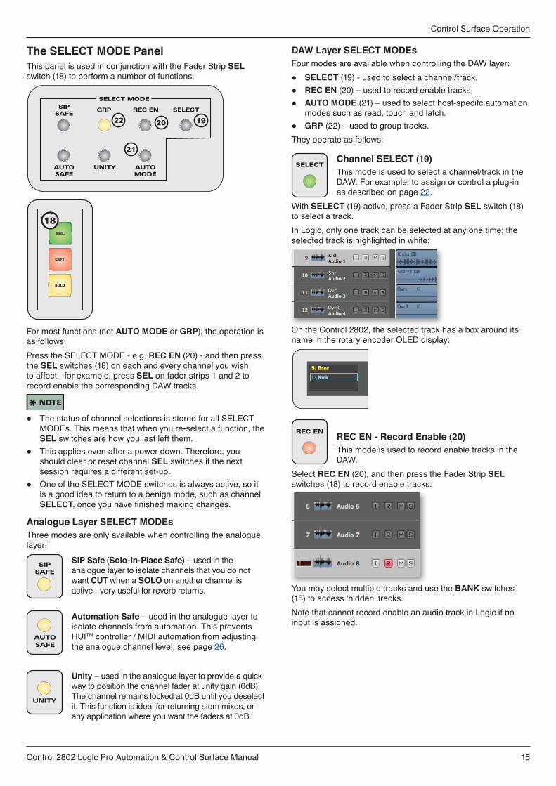
The SELECT MODE PanelThis panel is used in conjunction with the Fader Strip SEL switch (18) to perform a number of functions.
For most functions (not AUTO MODE or GRP), the operation is as follows:Press the SELECT MODE - e.g. REC EN (20) - and then press the SEL switches (18) on each and every channel you wish to affect - for example, press SEL on fader strips 1 and 2 to record enable the corresponding DAW tracks.
● The status of channel selections is stored for all SELECT MODEs. This means that when you re-select a function, the SEL switches are how you last left them.
● This applies even after a power down. Therefore, you should clear or reset channel SEL switches if the next session requires a different set-up.
● One of the SELECT MODE switches is always active, so it is a good idea to return to a benign mode, such as channel SELECT, once you have finished making changes.
Analogue Layer SELECT MODEsThree modes are only available when controlling the analogue layer:
SIP Safe (Solo-In-Place Safe) – used in the analogue layer to isolate channels that you do not want CUT when a SOLO on another channel is active - very useful for reverb returns.
Automation Safe – used in the analogue layer to isolate channels from automation. This prevents HUITM controller / MIDI automation from adjusting the analogue channel level, see page 26.
Unity – used in the analogue layer to provide a quick way to position the channel fader at unity gain (0dB). The channel remains locked at 0dB until you deselect it. This function is ideal for returning stem mixes, or any application where you want the faders at 0dB.
DAW Layer SELECT MODEsFour modes are available when controlling the DAW layer:
● SELECT (19) - used to select a channel/track. ● REC EN (20) – used to record enable tracks. ● AUTO MODE (21) – used to select host-specifc automation
modes such as read, touch and latch. ● GRP (22) – used to group tracks.
They operate as follows:
Channel SELECT (19)This mode is used to select a channel/track in the DAW. For example, to assign or control a plug-in as described on page 22.
With SELECT (19) active, press a Fader Strip SEL switch (18) to select a track. In Logic, only one track can be selected at any one time; the selected track is highlighted in white:
On the Control 2802, the selected track has a box around its name in the rotary encoder OLED display:
REC EN - Record Enable (20)This mode is used to record enable tracks in the DAW.
Select REC EN (20), and then press the Fader Strip SEL switches (18) to record enable tracks:
You may select multiple tracks and use the BANK switches (15) to access ‘hidden’ tracks.Note that cannot record enable an audio track in Logic if no input is assigned.

16 Control 2802 Logic Pro Automation & Control Surface Manual
Control Surface Operation
AUTO MODE (21)This mode is used to select the automation mode for each track.
The available modes in Logic are Read, Write, Touch, Latch and Off:
To change automation mode for a track or tracks:1. Select the AUTO MODE switch (21).The OLED displays update to show the automation modes at the bottom of each display - Read, Write, Touch, Latch. Use the right PAGE key (26) to access the next set of options - Trim and Off:
Note that Trim is NOT supported by Logic (this mode is available in ProTools only).2. Use the Fader Strip SEL switches (18) to select the tracks
you wish to alter.3. Then press down on an encoder to apply the option -
for example, press down on the first encoder to put all selected tracks into Read:
If you are using the analogue fader automation, then bank to the first 8 “dummy” tracks to set the
automation modes for your analogue fader layer.See page 27 for recommendations on writing and replaying automation in Logic.
GRP - Group Mode (22)This mode is used to add or remove tracks to existing Logic groups.
If you don’t have any groups in your Logic session, then pressing GRP (22) followed by a Fader Strip SEL switch (18) opens the ‘Groups’ dialogue box. Here you can set parameters for the group, using the mouse, such as linking Volume, Mute, Automation Mode, etc:
Please note that after the first group is created, creating new groups (>1) must be done via the mouse within Logic. This is due to a limitation of the HUITM protocol.We suggest that you create groups manually while organising your session. You can then use the GRP SELECT MODE (22) to assign tracks to existing Logic groups as follows:1. Select the GRP switch (22).2. Press the left and right PAGE keys (26), below the first
rotary encoder, to choose the Logic group - please see the note below.
3. Press the Fader Strip SEL switches (18) to assign tracks to the selected group.
A Note on Group SelectionUnfortunately, due to a restriction of the HUITM protocol, there is no visual feedback from Logic to the OLED displays. This means that when you PAGE left and right, you cannot be sure which group is selected. Therefore, use your Logic session to see which group is being assigned - for example, you will get a good overview of grouping from the ‘Mixer’ window:

Control Surface Operation
Control 2802 Logic Pro Automation & Control Surface Manual 17
DAW Meters (17)
The DAW METERS switch (17) changes the input to the LED bargraph meters globally across the console. This allows you to meter the 8 DAW tracks currently assigned to the console.Please note that this is a global command which changes the metering across all 8 channel strips.DAW Metering in Logic Session:
Control 2802 switched to DAW METERS:
0 VU is the centre of the meter scale and calibrated to a nominal operating level of +4dBu.Relative to a typical EBU AD/DA converter calibration of +18dBu = 0dBFS, this means that +4dBu = 0 VU = -14dBFS:
You can find more information on the channel bargraph meter in the “Control 2802 Operating Manual”.
Adjusting Parameters from the Rotary EncodersWhen controlling the DAW layer, the BANK and 5-8 switches allow you to assign different tracks from your DAW session onto the 4 rotary encoders. See page 13 for details.
Once assigned, you can use the encoders and OLED displays to control a number of track parameters. The different modes are accessed from the “encoder mode” switches:
● PAN (27) - ● AUX (28) - ● INSERT (29) - ● ASSIGN (30) -
Note that some modes can be combined to access more than one function.The controls operate in Logic’s ‘Mixer’ and ‘Arrange’ windows.
PAGE Keys (26)
The left and right PAGE keys, below the first rotary encoder, are used to scroll through parameter pages.For example, when editing aux sends, input and output routing, or plug-in insert effects, the available options may cover more than a single page. Scroll left to right through the pages to access all options - the OLED displays update accordingly.
18 Control 2802 Logic Pro Automation & Control Surface Manual
Control Surface Operation
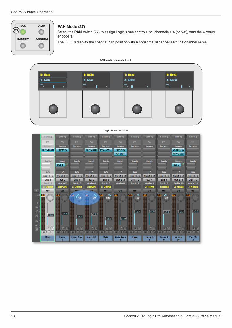
PAN Mode (27)Select the PAN switch (27) to assign Logic’s pan controls, for channels 1-4 (or 5-8), onto the 4 rotary encoders.The OLEDs display the channel pan position with a horizontal slider beneath the channel name.
PAN mode (channels 1 to 4):
Logic ‘Mixer’ window:

Control Surface Operation
Control 2802 Logic Pro Automation & Control Surface Manual 19
I/O Assignment - PAN (27) + ASSIGN (30)By pressing the ASSIGN switch (30) when in PAN mode, the encoders provide access to channel input and output routing - ideal for assigning inputs when recording, or configuring output bussing during mixdown.Input assignments are set on the first page. Use the PAGE keys (26) to access output assignments on page 2. When dealing with outputs, you may assign onto busses as well as to physical outputs.
To change an assignment, rotate the encoder to the desired input, bus or output - your selection flashes on the OLED display. Press down on the encoder to confirm the assignment.
Input Assignments (channels 1 to 4):
Output Assignments (channels 1 to 4):
For faster session setups, try using the Logic I/O labelling system (opposite) to rename inputs,
outputs and buses. The HUITM protocol transfers only 4 characters to the control surface, therefore if you use short names, this will make assignments from the console much easier.

20 Control 2802 Logic Pro Automation & Control Surface Manual
Control Surface Operation
AUX Mode (28)Select the AUX switch (28) to assign one of Logic’s bus sends, for channels 1-4 (or 5-8), onto the 4 rotary encoders. You can control any one of the first five bus send positions - use the PAGE keys (26) to select the send. The OLEDs show the name of the send - e.g. Snd1 - and the send level position beneath the channel name.Although the OLEDs provide access to all five sends (Snd1 to Snd5), levels can ONLY be adjusted if a
bus is assigned to the send position on the channel. If no bus is assigned, then you cannot turn up the level. Note also, that any bus may be assigned to the five send positions, either in Logic’s ‘Mixer’ window using the mouse, or from the console in AUX + ASSIGN mode.
AUX mode (channels 1 to 4) - controlling Send 1:
Aux Send to FadersPress the AUX switch (28) again - it flashes - to put the send levels onto the 8 channel faders. You can now use the 8 channel faders to adjust the bus send levels for the selected send. Use the PAGE keys (26) to change the send (Snd1 to Snd5). This mode is ideal for setting up a quick headphone balance or effects send across your 8 DAW channels.In our example, the console faders are controlling Logic’s Bus 1 sends - which have been assigned to the send 2 position (Snd2):
Logic Sends (in the ‘Mixer’ window):
Aux to Fader Flip Mode:

Control Surface Operation
Control 2802 Logic Pro Automation & Control Surface Manual 21
Aux Send Assignment - AUX (28) + ASSIGN (30)By pressing the ASSIGN switch (30) when in AUX mode, the encoders can be used to assign busses to the first five send positions (Snd1 to Snd5).
First select the send you wish to assign, by using the PAGE keys (26) to scroll through the slot positions: S1 to S5.Then rotate the encoder to select the desired bus - your selection flashes on the OLED display. Press down on the encoder to confirm the assignment.
Aux Send Assignments (channels 1 to 4):
Bus Options in Logic:

22 Control 2802 Logic Pro Automation & Control Surface Manual
Control Surface Operation
INSERT Mode (29)This mode can be used to assign plug-ins to any of the first four insert slots in Logic, and control the plug-in parameters.Please note that ASSIGN cannot be selected in INSERT mode.
To assign a Plug-in:1. Select the track you wish to affect - press SELECT (19), on the SELECT MODE panel, and then press a Fader Strip SEL switch
(18) - the selected channel has a box around its name in the rotary encoder OLED display:
2. Select INSERT (29) - the OLEDs update to show Logic’s first four insert slots for the selected channel (Insrt1Plg to Insrt4Plg) - if you already have a plug-in assigned, then you see its name in blue on the corresponding display.
Please note that if you select INSERT (29) first, and then change your channel selection (18), the OLEDs temporarily display the name of the selected channel:
3. Rotate an encoder to select a plug-in - your selection flashes on the OLED display. 4. Press down on the encoder to confirm the assignment:
At this point, the plug-in window will open within Logic. You can now control the parameters from the rotary encoders as described on the next page.If you wish to close the plug-in window, press down (tap) the INSERT switch (29).If the plug-in has been added manually, from within Logic, you may have to refresh the Control 2802 displays by tapping the INSERT switch again.To open a plug-in window that is currently closed, tap down on the corresponding encoder - the plug-in window opens in Logic (and the OLEDs update to show the parameter editing mode. Tap the INSERT switch to close the plug-in window on Logic, and return the OLEDs to the insert plug-in view.
Control Surface Operation
Control 2802 Logic Pro Automation & Control Surface Manual 23
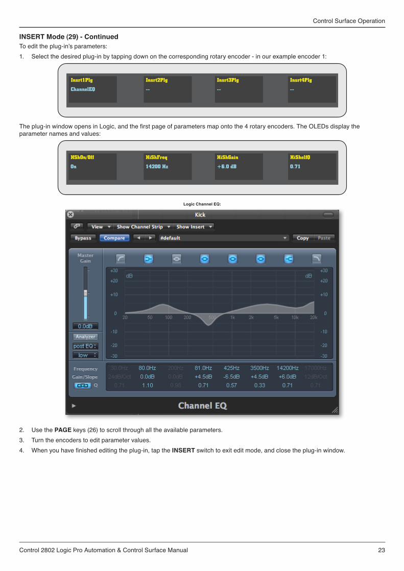
INSERT Mode (29) - ContinuedTo edit the plug-in’s parameters:1. Select the desired plug-in by tapping down on the corresponding rotary encoder - in our example encoder 1:
The plug-in window opens in Logic, and the first page of parameters map onto the 4 rotary encoders. The OLEDs display the parameter names and values:
Logic Channel EQ:
2. Use the PAGE keys (26) to scroll through all the available parameters.3. Turn the encoders to edit parameter values.4. When you have finished editing the plug-in, tap the INSERT switch to exit edit mode, and close the plug-in window.

24 Control 2802 Logic Pro Automation & Control Surface Manual
Control Surface Operation
Function Keys
The function keys F1 to F4 (25) are provided for future expansion of user programmable commands.Their default configuration, within the HUITM protocol and Logic implementation, is as follows:
● F1 Clear overload flag in audio channels ● F2 Recall screenset 2 ● F3 Recall screenset 3 ● F4 Recall screenset 4
Please consult your Logic manual, and Logic Control Surfaces Support document, to learn about modifying these key commands within your host software.
Console SETUP
The SETUP switch (2) allows you to access a number of useful networking parameters, set the host DAW platform and check your current firmware revision.
Press SETUP and the OLED displays will show the first page of the setup menu. To change page, use the page keys (26) located under the left most encoder.
Editing Setup ParametersTo edit parameters, rotate the corresponding rotary encoder to change the value - the SETUP LED flashes to indicate the change.
Press the SETUP switch to confirm and apply the changes.The SETUP LED returns to a solid red once changes are confirmed.
The first five SETUP pages are described in more detail during the network setup procedure on page 6:
Page 1 – Host Software
Page 2 – Use DHCP (networking option)
Page 3 – IP Address (networking option)
Page 4 – Subnet Mask (networking option)
Page 5 – Port (networking option)
Page 6 – Factory ResetPress down on the rotary encoder to reset the console to its factory default settings.
Note that this will reset the analogue main channel levels and motorised faders to “off”.
Pages 7 & 8 – Serial Number & Firmware Info
These pages are for information purposes only.

Analogue Fader & CUT Automation
Control 2802 Logic Pro Automation & Control Surface Manual 25
Analogue Fader & CUT AutomationHUITM / MIDI automation from your DAW can be applied to Control 2802’s analogue channel levels and motorised faders. This allows you to automate the faders and CUTs of the 8 analogue main channel paths - ideal if you wish to sum using the analogue mix bus, but still have automated control.
CUTs as well as faders can be automated - this is ideal for muting analogue channels (with inserts) during quiet sections of the mix, and thereby reducing any unwanted noise from vintage outboard.The analogue automation works along side the full DAW control surface layer. This means that fader and cut automation can be written and replayed on both the DAW and anaogue fader layers.
The diagram below provides an overview of the analogue automation system and the parameters that can be controlled:
The sections of most interest when using the analogue automation are:
● Faders ● CUT switches ● AUTO MODE and AUTO SAFE SELECT MODEs ● DAW Transport Control

26 Control 2802 Logic Pro Automation & Control Surface Manual
Analogue Fader & CUT Automation
Preparing for Analogue AutomationConfigurationThe analogue automation works by setting up 8 “dummy” audio channels in your DAW - blank channels that contain no audio. Then using these to write and replay automation to the 8 analogue faders and CUTs of Control 2802.See page 10 for details on configuration. If the setup is correct, then the 8 “dummy” tracks appear at the beginning of the Logic session. They are indicated by a white marker in the track header (the default colour):
Note: if your analogue channels are not in AUTO SAFE, then controlling the “dummy” track faders and mutes from the DAW layer will affect your analogue channel levels! If you find this confusing, you can hide these tracks using Logic’s ‘Hide’ functionality, see page 27. Note, however, that you will need to control the tracks from the DAW layer in order to set the automation mode from the console (see below).
Setting the Automation ModeUse the DAW layer switch (on the Control Surface Panel) to flip the Fader Strips to the DAW fader layer, and navigate to the 8 “dummy” tracks.By controlling the 8 tracks in the DAW layer, you can set the AUTO MODE for each channel. This will determine how the faders and CUTs write (and replay) automation within Logic. See page 16 for details on automation modes.
Enabling Automation (turn off AUTO SAFE)AUTO SAFE is a SELECT MODE, used in the analogue layer to isolate channels from automation - it prevents HUITM controller / MIDI automation from adjusting the analogue channel level.Please note that AUTO SAFE is turned ON across ALL channels by factory default. Therefore, to automate a channel, you must turn AUTO SAFE off. The status of AUTO SAFE is then stored, if you exit the mode or power down. This means that when you re-enter AUTO SAFE, your last used settings are recalled.To enable the analogue channels for automation:1. Use the DAW switch to flip the Fader Strips back to the
analogue fader layer. (AUTO SAFE can only be selected when controlling the analogue layer).
2. Press the AUTO SAFE SELECT MODE switch on the Control Surface Panel.
3. Then press the SEL switches, on the Fader Strips, to enable or isolate the analogue channels:
● SEL switch LED on = channel is isolated. ● SEL switch LED off = channel is enabled for automation.
If automation is already written for the analogue layer, AUTO SAFE can be used to isolate the channels to prevent moves playing back. This is ideal for trying out fader rides before writing a new automation pass, without “fighting” existing automation data.
Writing and Replaying Analogue AutomationHaving prepared your channels, you can now use the console’s TRANSPORT panel to control the DAW playback, and write/replay automation for the analogue layer.Just treat the analogue fader and CUT automation like any other channel in your DAW mix:
● Use the DAW layer switch (on the Control Surface Panel) to flip the Fader Strips between the DAW and analogue layers.
● View your analogue automation on the first 8 “dummy” tracks of your Logic session.

Automation - Tips and Suggestions
Control 2802 Logic Pro Automation & Control Surface Manual 27
Automation - Tips and SuggestionsWhether you are writing automation on your DAW or analogue layer, the following tips and suggestions apply.
Automation Modes in LogicWe recommend the use of Touch, Latch and Read mode for the majority of your work. Touch mode provides the most essential workflow, writing automation data when a fader is touched or moved, and returning to previously recorded automation data when a fader is released.Note that the Control 2802 faders are motorised and touch sensitive.Latch mode is useful, but will write up to the last touched fader position unless playback is stopped. Therefore, you may overwrite important rides. If so, use the stages of undo in your DAW.Read mode is used to play back automation data.Be very careful if using Write mode, as Logic may automate any paramater touched - plug-ins, EQ bands, everything if you’re not careful!
Writing and Viewing Automation in LogicFader rides and mutes can be recorded into Logic and viewed, edited or manually drawn, as in any other DAW-based automation system.To view your recorded automation press ‘A’ on your computer keyboard (this is a standard Logic keyboard shortcut). Or click on the automation icon at the top of the screen.
Hiding Tracks in LogicWhen running automation on both DAW and analogue fader layers, you may find it useful to hide the analogue automation tracks (1-8). Hiding the tracks still allows the automation data to function but keeps your session tidy.Note that you can only access this option if you set Channel Strip View to Tracks Only during step 2 of the HUITM controller configuration, see page 9.Select the tracks you wish to hide by clicking on the small ‘H’ beside each channel. Then, to hide (or show) the tracks, press ‘H’ on your computer keyboard. Or click on the small ‘H’ hide icon at the top of the ‘Arrange’ window.

28 Control 2802 Logic Pro Automation & Control Surface Manual
Future Updates
Future UpdatesWhen updates are released to improve control surface workflow, bug fixes and add new features, you will need to update the console firmware.To do this please visit www.focusrite.com to obtain the latest firmware from the Control 2802 webpage. Then follow the simple instructions provided with the firmware download to flash the upgrade to the console memory.If you experience any issues please read the Control 2802 FAQ found online at www.focusrite.com.Thanks from the Focusrite team.

Panel Visualisation
Control 2802 Logic Pro Automation & Control Surface Manual 29
Panel Visualisation