long-baseline neutrino experiment (lbne) project ...lbne2-docdb.fnal.gov/0050/005017/004/cdr-vol_6...
TRANSCRIPT
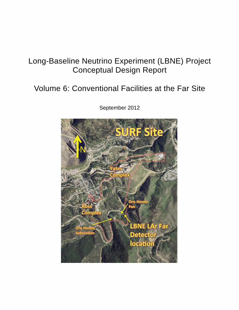
Long-Baseline Neutrino Experiment (LBNE) Project Conceptual Design Report
Volume 6: Conventional Facilities at the Far Site
September 2012


i
Contents
Contents ....................................................................................................................................... i
Acronyms and Abbreviations ................................................................................................... iii
List of Figures ............................................................................................................................. v
List of Tables ............................................................................................................................. vii
1 Introduction ...................................................................................................................... 1-1
1.1 Introduction to LBNE .................................................................................................. 1-1
1.1.1 About this Conceptual Design Report .................................................................... 1-1
1.1.2 LBNE and the U.S. Neutrino-Physics Program ...................................................... 1-2
1.1.3 LBNE Project Organization .................................................................................... 1-3
1.1.4 Principal Parameters of the LBNE Project ............................................................. 1-3
1.1.5 Supporting Documents ........................................................................................... 1-3
1.2 Introduction to LBNE Conventional Facilities at the Far Site ...................................... 1-4
1.3 Participants................................................................................................................. 1-6
1.4 Codes and Standards................................................................................................. 1-6
2 Existing Site Conditions .................................................................................................. 2-8
2.1 Existing Site Conditions ............................................................................................ 2-12
2.1.1 Existing Facilities and Site Assessment ............................................................... 2-12
2.2 Geology and Existing Excavations ........................................................................... 2-16
2.2.1 Geologic Setting ................................................................................................... 2-17
2.2.2 Rock Mass Characterization ................................................................................ 2-17
2.2.3 Geologic Conclusions ........................................................................................... 2-19
3 The Facility Layout ......................................................................................................... 3-20
3.1 Project-Wide Considerations .................................................................................... 3-22
3.1.1 Environmental Protection ..................................................................................... 3-22
3.1.2 Safeguards and Security ...................................................................................... 3-23
3.1.3 Emergency Shelter Provisions ............................................................................. 3-23
3.1.4 Energy Conservation ............................................................................................ 3-23
3.1.5 DOE Space Allocation .......................................................................................... 3-24

ii
3.2 Sitework and Site Infrastructure (WBS 130.06.03.05.02.01) .................................... 3-24
3.2.1 Site Preparation .................................................................................................... 3-24
3.2.2 Infrastructure ........................................................................................................ 3-27
3.3 Service, Support Buildings and Outfitting (WBS 130.06.03.05.02.02) .................... 3-35
3.3.1 Ross Dry ............................................................................................................... 3-36
3.3.2 Temporary Warehouse and Office Space ............................................................ 3-37
3.3.3 Detector Site Buildings ......................................................................................... 3-37
3.3.4 Cryogenic Equipment Building ............................................................................. 3-37
3.3.5 Purification Building .............................................................................................. 3-38
3.3.6 Fill Station ............................................................................................................. 3-38
3.3.7 Other structures .................................................................................................... 3-38
3.4 LAr Excavation and Pit Construction (WBS 130.06.03.05.03.01) ........................... 3-38
3.4.1 Structural .............................................................................................................. 3-41
3.4.2 Interfaces between LAr-FD and Excavation ......................................................... 3-41
3.5 Detector Hall Construction (WBS 130.06.03.05.03.02) ............................................ 3-42
References ................................................................................................................................. 45

iii
Acronyms and Abbreviations
2D, 3D two dimensional, three dimensional ACAMS Asset Control and Alarm Monitoring System ACBM asbestos-containing building material ACH Air Changes (per hour) AHU Air Handling Unit AoR Area of Refuge APTS asset and personnel tracking system C Celsius CDR Conceptual Design Report CF Conventional Facilities CFM cubic feet per minute CR communications room dBA decibel DDC Direct Digital Control DocDB LBNE’s document database (LBNE-doc-####) DOE Department of Energy DUSEL Deep Underground Science and Engineering Laboratory EMI Electromagnetic Interference EPA Environmental Protection Agency ES&H Environment, Safety and Health F Fahrenheit FEA Finite Element Analysis FEMA Federal Emergency Management Agency Fermilab Fermi National Accelerator Laboratory FLS fire life safety FMS Facility Management System ft feet GAC Geotechnical Advisory Committee GES Geotechnical Engineering Services gpm gallons per minute gsf gross square feet HMI Human Machine Interface Hp Horse Power HUD Department of Housing and Urban Development HVAC Heating, Ventilation and Air Conditioning IBC International Building Code in inch IT Information Technology ksi kilopascal kt (or kton) kiloton kV kilovolt

iv
kVA kilo volt amps (or kilowatt, electrical power) kW kilowatt L Level/Liter LAr Liquid Argon LAr-FD Liquid Argon Far Detector LBNE Long Baseline Neutrino Experiment LBP lead-based paint LCAB Large Cavity Advisory Board LFA Lachel Felice & Associates LHD Load Haul Dump m meter m3 cubic meter MBH thousands of BTU’s per hour MDU Montana-Dakota Utilities MEP mechanical/ electrical/ plumbing MER Mechanical Electrical Room MK McCarthy Kiewit Joint Venture mm millimeter MPa megapascal MSHA Mine Safety and Health Administration MUTCD Manual of Uniform Traffic Control Devices NEC National Electric Code NEPA National Environmental Policy Act NESC National Electric Safety Code NFPA National Fire Protection Association NPDES National Pollutant Discharge Elimination System NSF National Science Foundation ODH Oxygen Deficiency Hazard P5 Particle Physics Project Prioritization Panel PCB polychlorinated biphenyl PDR Preliminary Design Report (DUSEL) PRV pressure reducing valve assembly psi pounds per square inch REED (South Dakota) Research, Education and Economic Development (Network) RFID Radio Frequency Identification RPBP reduced pressure backflow preventer SD SHPO South Dakota State Historic Preservation Office SDSTA South Dakota Science and Technology Authority sf square feet UPS uninterruptible power supply v volt VoIP Voice over Internet Protocol WBS Work Breakdown Structure WCD water Cherenkov detector WWTP Waste Water Treatment Plant yd3 cubic yard

v
List of Figures
Figure 1-1: Location of LAr-FD at Surface. [LBNE] .................................................................... 1-5
Figure 2-1: Regional Context showing the city of Lead, South Dakota. [Dangermond Keane Architecture, Courtesy SURF] .................................................................................................... 2-9
Figure 2-2: SURF Complex shown in the context of the city of Lead, South Dakota, and the property remaining under ownership of Barrick. Area shown in yellow is a potential future expansion of the SDSTA property. [Dangermond Keane Architecture, Courtesy of SURF] .... 2-10
Figure 2-3: SURF Yates Campus shown on the left and Kirk Canyon to the right. [Courtesy of SURF] ...................................................................................................................................... 2-11
Figure 2-4: Aerial view of SURF (boundary in red) and the adjacent city of Lead. [Dangermond Keane Architecture, Courtesy of SURF] .................................................................................. 2-11
Figure 2-5: Historic photo of milling operation, Yates Headframe, Hoist, and Foundry. [Courtesy Homestake Adams Research and Cultural Center] ................................................................. 2-15
Figure 2-6: Map of Lead Historic District. [Dangermond Keane Architecture, Courtesy of SURF] ................................................................................................................................................. 2-16
Figure 3-1: SURF architectural site plan. LBNE facilities will be sited near the Oro Hondo Campus. [HDR] ........................................................................................................................ 3-20
Figure 3-2: Ross Campus Architectural Site Plan. [HDR] ........................................................ 3-21
Figure 3-3: Oro Hondo Campus Site Plan. [HDR] ................................................................... 3-22
Figure 3-4: LAr-FD coverage at 20° from horizontal in beam line direction. [HDR] ................ 3-25
Figure 3-5: Retaining walls and site layout. [HDR] .................................................................. 3-26
Figure 3-6: Waste Rock Disposal Area. [HDR] ........................................................................ 3-27
Figure 3-7: Supply Power for LAr-FD at Surface. [HDR] ......................................................... 3-28
Figure 3-8: One Line Diagram for LAr-FD at Surface. [SURF]................................................. 3-29
Figure 3-9: Oro Hondo Campus Water Main path shown in blue. [HDR] ................................ 3-33
Figure 3-10: Site plan showing storm sewer path. Storm sewer route is shown in red with the storm sewer inlet on the left side of the site (higher elevation), re-routing below grade around the Detector Pit, and discharging the storm water on the lower side of the site retaining wall on the right side of the plan. [HDR] ............................................................................................... 3-34
Figure 3-11: 100-year flood plain for White Wood Creek showing the relative position to the detector site. [HDR] .................................................................................................................. 3-35
Figure 3-12: Photo of Ross Dry Exterior. [HDR] ...................................................................... 3-36
Figure 3-13: Location of the new LAr-FD control room within the Ross Dry. For orientation, the lower right corner of this plan corresponds with corner of the building visible in Figure 3-12. Note

vi
that this figure was created for an alternate configuration; the LAr 4850L Control Room is in the same location as the LAr-FD control room. [HDR] ................................................................... 3-36
Figure 3-14: Site Buildings. [HDR] ........................................................................................... 3-37
Figure 3-15: Cross Section of the 10kT LAr-FD taken parallel to the beamline. [LBNE] ......... 3-39
Figure 3-16: Cross Section of the 10 kT LAr-FD taken perpendicular to the beamline. [LBNE] .. 3-40
Figure 3-17: LAr-FD Pit ground support used by Fermilab’s NOvA Project. [Burns and McDonnell] ............................................................................................................................... 3-41
Figure 3-18: Plan view of Detector Hall. Note the over-the-road truck access and staging areas between this access and the detector. [Fermilab] .................................................................... 3-43
Figure 3-19: Wall descriptions and sizes. [HDR] ..................................................................... 3-44

vii
List of Tables
Table 1-1: LBNE Principal Parameters. ..................................................................................... 1-3
Table 1-2: LBNE CD-1 Documents. ........................................................................................... 1-4
Table 3-1: Electrical Load Table. ............................................................................................. 3-29


Chapter 1: Introduction 1-1
LBNE Conceptual Design Report
1 Introduction
1.1 Introduction to LBNE
The Long-Baseline Neutrino Experiment (LBNE) Project team has prepared this Conceptual Design Report (CDR) which describes a world-class facility to enable a compelling research program in neutrino physics. The ultimate goal in the operation of the facility and experimental program is to measure fundamental physical parameters, explore physics beyond the Standard Model and better elucidate the nature of matter and antimatter.
Although the Standard Model of particle physics presents a remarkably accurate description of the elementary particles and their interactions, it is known that the current model is incomplete and that a more fundamental underlying theory must exist. Results from the last decade, revealing that the three known types of neutrinos have nonzero mass, mix with one another and oscillate between generations, point to physics beyond the Standard Model. Measuring the mass and other properties of neutrinos is fundamental to understanding the deeper, underlying theory and will profoundly shape our understanding of the evolution of the universe.
1.1.1 About this Conceptual Design Report
The LBNE Conceptual Design Report is intended to describe, at a conceptual level, the scope and design of the experimental and conventional facilities that the LBNE Project plans to build to address a well-defined set of neutrino-physics measurement objectives. At this Conceptual Design stage the LBNE Project presents a Reference Design for LBNE and alternative designs that are still under consideration for particular elements.
an intense neutrino beam aimed at a far site
detectors located downstream of the neutrino source
a massive neutrino detector located at the far site
construction of conventional facilities at both the near and far sites
The selected near and far sites are Fermi National Accelerator Laboratory (Fermilab), in Batavia, IL and Sanford Underground Research Facility (SURF), respectively. The latter is the site of the formerly proposed Deep Underground Science and Engineering Laboratory (DUSEL) in Lead, South Dakota.
This CDR is organized into six stand-alone volumes, one to describe the overall LBNE Project and one for each of its component subprojects:

1-2 Chapter 1: Introduction
Volume 6: LBNE Conventional Facilities at the Far Site
Volume 1: The LBNE Project
Volume 2: The Beamline at the Near Site
Volume 3: Detectors at the Near Site
Volume 4: The Liquid Argon Detector at the Far Site
Volume 5: Conventional Facilities at the Near Site
Volume 6: Conventional Facilities at the Far Site
Volume 1 is intended to provide readers of varying backgrounds an introduction to LBNE and to the following volumes of this CDR. It contains high-level information and refers the reader to topic-specific volumes and supporting documents, listed in Section 1.1.5. Each of the other volumes contains a common, brief introduction to the overall LBNE Project, an introduction to the individual subproject, and a detailed description of its conceptual design.
1.1.2 LBNE and the U.S. Neutrino-Physics Program
In its 2008 report, the Particle Physics Project Prioritization Panel (P5) recommended a world-class neutrino-physics program as a core component of the U.S. particle physics program [1]. Included in the report is the long-term vision of a large detector at the formerly proposed Deep Underground Science and Engineering Laboratory (DUSEL) in Lead, S.D. (now SURF), and a high-intensity neutrino source at Fermilab.
On January 8, 2010, the Department of Energy (DOE) approved the Mission Need for a new long-baseline neutrino experiment that would enable this world-class program and firmly establish the U.S. as the leader in neutrino science. The LBNE Project is designed to meet this Mission Need.
With the facilities provided by the LBNE Project, the LBNE Science Collaboration proposes to mount a broad attack on the science of neutrinos with sensitivity to all known parameters in a single experiment. The focus of the program will be the explicit demonstration of leptonic CP violation, if it exists, by precisely measuring the asymmetric oscillations of muon-type neutrinos and antineutrinos into electron-type neutrinos and antineutrinos.
The experiment will result in precise measurements of key three-flavor neutrino-oscillation parameters over a very long baseline and a wide range of neutrino energies, in particular, the CP-violating phase in the three-flavor framework and the mass ordering of neutrinos. The unique features of the experiment – the long baseline, the broad-band beam, and the high resolution of the detector – will enable the search for new physics that manifests itself as deviations from the expected three-flavor neutrino-oscillation model. The scientific goals and capabilities of LBNE are outlined in Volume 1 of this CDR and the 2010 Interim Report of the Long-Baseline Neutrino Experiment Collaboration Physics Working Groups [2].
Siting the Far Detector deep underground, a scope opportunity that LBNE may seek to pursue in the future with non-DOE funding, would provide opportunities for research in additional areas of physics, such as nucleon decay and neutrino astrophysics, in particular, studies of neutrino bursts from supernovae occurring in our galaxy.

Chapter 1: Introduction 1-3
LBNE Conceptual Design Report
1.1.3 LBNE Project Organization
The LBNE Project Office at Fermilab is headed by the Project Director and assisted by the Project Manager, Project Scientist and Project Systems Engineer. Project Office support staff include a Project Controls Manager and supporting staff, a Financial Manager, an Environment, Safety and Health (ES&H) Manager, a Computing Coordinator, Quality Assurance, Procurement and Risk Managers, a documentation team and administrative support.
The Beamline, Liquid Argon Far Detector and Conventional Facilities subprojects are managed by the Project Office at Fermilab, while the Near Detector Complex subproject is managed by a Project Office at Los Alamos National Laboratory (LANL).
More information on Project Organization can be found in Volume~1 of this CDR. A full description of LBNE Project management is contained in the LBNE Project Management Plan [3].
1.1.4 Principal Parameters of the LBNE Project
The principal parameters of the major Project elements are given in Table 1-1.
Table 1-1: LBNE Principal Parameters.
Project Element Parameter Value Near- to Far-Site Baseline 1,300 km Primary Beam Power 708 kW, upgradable to 2.3 MW Protons on Target per Year 6.5 x 10²⁰ Primary Beam Energy 60–120 GeV (tunable) Primary Beam Type Horn-focused with decay volume Neutrino Beam Energy Range 0.5–5 GeV Neutrino Beam Decay Pipe Diameter x Length 4 m × 204 m Near Site Neutrino Detector Type LArTPC Near Site Neutrino Detector Active Mass 18 ton Far Detector Type LArTPC Far Detector Active (Fiducial Mass) 35 (10) kton Far Detector Depth 3 m overburden
1.1.5 Supporting Documents
A host of information related to the CDR is available in a set of supporting documents. Detailed information on risk analysis and mitigation, value engineering, ES&H, costing, project management and other topics not directly in the design scope can be found in these documents, listed in Table 1-2. Each document is numbered and stored in LBNE’s document database, accessible via a username/password combination provided by the Project. Project documents stored in this database are also made available to internal and external review committees through Web sites developed to support individual reviews.

1-4 Chapter 1: Introduction
Volume 6: LBNE Conventional Facilities at the Far Site
Table 1-2: LBNE CD-1 Documents.
Title LBNE doc Number(s) Alternatives Analysis 4382 Case Study Report; Liquid Argon TPC Detector 3600 Configuration Management Plan 5452 DOE Acquisition Strategy for LBNE 5442 DOE Preliminary Project Execution Plan 5443 Integrated Environment, Safety & Health Management Plan 4514 LAr-FD Preliminary ODH Analysis 2478 LBNE Reconfiguration Final Report Linked from
LBNE web site (lbne.fnal.gov) under “Reports and Documents”
Global Science Objectives & Science Requirements, and Traceback Reports
4772
Preliminary Hazard Analysis Report 4513 Preliminary Security Vulnerability Assessment Report 4826 Procurement Plan 5329 Project Management Plan 2453 Project Organization Chart 5449 Quality Assurance Plan 2449 Report on the Depth Requirements for a Massive Detector at Homestake
0034
Requirements, Beamline 4835 Requirements, Far Detector 3747 Requirements, Far Site Conventional Facilities 4958 Requirements, Near Detectors 5579 Requirements, Near Site Conventional Facilities 5437 Risk Management Plan 5749 Value Engineering Report 3082 Work Breakdown Structure 4219
1.2 Introduction to LBNE Conventional Facilities at the Far Site
The goal of the LBNE Project is to explore physics beyond the Standard Model including the mass spectrum of the neutrinos and their properties by aiming an intense proton beam created at the Fermilab Main Injector at neutrino detectors more than 1,300 kilometers away. The preferred physics location for LBNE far detector is the Sanford Underground Research Facility (SURF) at Homestake in Lead, South Dakota. This site was originally selected as part of a National Science Foundation effort to create a deep underground science and engineering laboratory and again confirmed through the LBNE reconfiguration process. This process is discussed further in the LBNE Alternatives Analysis [4], where the scientific reasons for this location are detailed.
SURF is located at the site of the former Homestake Gold Mine, which is no longer an active mine. It is now being repurposed and modified to accommodate underground science. There are extensive underground workings that provide access to a depth of 8,000 ft.
The reference conceptual design for the far detector is a 10-kT Liquid Argon (LAr) detector (referred to as the Liquid Argon Far Detector or LAr-FD). The mass of fluid quoted is the fiducial portion of the

Chapter 1: Introduction 1-5
LBNE Conceptual Design Report
detector – the mass of vital importance for physics requirements. Excavated space for the detector will be larger than the fiducial. The LAr-FD is designed to be constructed at the surface of the facility near the Oro Hondo Shaft (see Figure 1-1). Refer to LBNE CDR Volume 4 for additional information on the Far Detector design.
The scope of the facilities required for the LAr-FD includes new cut and fill excavation and site leveling at the surface for the detector, buildings for experimental equipment, roads for access, utility supplies, as well as construction-required space. Infrastructure provided by Conventional Facilities for the experiment includes power to experimental equipment, cooling systems, and cyberinfrastructure. Additional infrastructure for the facility includes industrial water for process and fire suppression, fire detection and alarm, normal and standby power systems, drainage systems for water around the detector and cyberinfrastructure for communications and security.
Figure 1-1: Location of LAr-FD at Surface. [LBNE]
In addition to providing new spaces and infrastructure, Conventional Facilities will provide infrastructure in some existing spaces for LAr-FD use. Examples of existing spaces and infrastructure that require upgrades to meet LBNE needs include upgrades to the fiber optic systems and installation of a control room in the existing Ross Dry building, and modification to the existing substation at the Oro Hondo Campus.

1-6 Chapter 1: Introduction
Volume 6: LBNE Conventional Facilities at the Far Site
1.3 Participants
The Far Detector is planned to be located at the SURF site, which is managed by the South Dakota Science and Technology Authority (SDSTA). The design and construction of LBNE Far Site Conventional Facilities will be executed in conjunction with SURF staff.
The LBNE Project Conventional Facilities is managed by staff organized according to the Work Breakdown Structure (WBS) and is led by the Conventional Facilities Project Manager (WBS Level 2). The supporting team includes a Conventional Facilities Level 3 Far Site Manager, who is a member of and works directly with the SURF engineering staff. The Level 3 Far Site Manager is also the liaison between the Conventional Facilities Level 2 Project and the LAr Level 2 Project to ensure the detector requirements are met and is responsible for all LBNE scope at the Far Site. The SURF Director of Engineering is currently filling this role.
To date, SURF has utilized a team of in-house facility engineers to oversee multiple engineering, design and construction consultants for a variety of LBNE design configurations and other projects. Design consultants have specific areas of expertise in excavation, rock support, fire/life safety, electrical power distribution, cyberinfrastructure, cooling with chilled water, and heating/ventilation systems. Design consultants for LBNE’s prior configurations of the conceptual design included: HDR for surface facilities; Arup, USA for underground infrastructure; and Golder Associates for excavation. During the design process, interaction between SURF facility engineers, LBNE Far Site project team, and design consultants was conducted via weekly telephone conferences, periodic design interface workshops, and electronic mail. The SURF facility engineers coordinated all information between design consultants to assure that design efforts remain on track. The work performed during earlier iterations of the design effort was utilized to develop the scope of work described herein as the reference design for CD-1. The reference design was developed by SURF, LBNE, HDR, and Albertson Engineering.
For the prior LBNE conceptual designs, the McCarthy Kiewit Joint Venture (MK) performed as the construction manager for pre-construction services. MK reviewed the consultant designs for constructability and provided independent estimates of cost and schedule. These independent cost and schedule estimates were reconciled with the design contractor cost and schedule estimates, and have since been used as the basis for the cost and schedule estimates for this scope of work. The reference design also incorporates some actual construction cost elements from the NOvA Project recently constructed in Ash River, Minnesota.
1.4 Codes and Standards
Conventional Facilities to be constructed at the Far Site will be designed and constructed in conformance with the SURF ESH Standards [5], and the latest edition of the following codes and standards:
Applicable Federal Code of Federal Regulations (CFR), Executive Orders, and DOE Requirements
2009 International Building Code (IBC)
Sanford Underground Research Facility Design Criteria, EHS-1000-L3-05

Chapter 1: Introduction 1-7
LBNE Conceptual Design Report
“Fire Protection/Life Safety Assessment for the Conceptual Design of the Far Site of the Long Baseline Neutrino Experiment (LBNE)”, a preliminary assessment dated October 11, 2011, by Aon/Schirmer Engineering
The Occupational Health and Safety Act of 1970 (OSHA)
Mine Safety and Health Administration (MSHA)
NFPA 101, Life Safety Code
NFPA 520, Standard on Subterranean Spaces, 2005 Edition
NFPA 72, National Fire Alarm Code
American Concrete Institute (ACI) 318
American Institute of Steel Construction Manual, 14th Edition
ASHRAE 90.1-2007, Energy Standard for Buildings
ASHRAE 62, Indoor Air Quality
2009 National Electrical Code (NEC)
American Society of Mechanical Engineers (ASME)
American Society for Testing and Material (ASTM)
American National Standards Institute (ANSI)
National Institute of Standards & Technology (NIST)
Insulated Cable Engineers Association (ICEA)
Institute of Electrical and Electronics Engineers (IEEE)
National Electrical Manufacturers Association (NEMA)
American Society of Plumbing Engineers (ASPE)
American Water Works Association (AWWA)
American Society of Sanitary Engineering (ASSE)
American Gas Association (AGA)
National Sanitation Foundation (NSF)
Federal American's with Disabilities Act (ADA) along with State of South Dakota ADA amendments. These requirements shall only be applied to those facilities which are located at the ground surface and accessible to the public.

2-8 Chapter 2: Existing Site Conditions
Volume 6: LBNE Conventional Facilities at the Far Site
2 Existing Site Conditions
The SDSTA currently operates and maintains Sanford Underground Research Facility (SURF) at Homestake in Lead, South Dakota. The SURF property comprises 186 acres on the surface and 7,700 acres underground. The SURF surface campus includes approximately 253,000 gross square feet (gsf) of existing structures. Using a combination of private funds through T. Denny Sanford, South Dakota Legislature-appropriated funding, and a federal Department of Housing and Urban Development (HUD) Grant, the SDSTA has made significant progress in stabilizing and rehabilitating the Sanford Underground Research Facility to provide for safe access and prepare the site for new laboratory construction. These efforts have included dewatering of the underground facility and mitigating and reducing risks independent of the former Deep Underground Science and Engineering Laboratory (DUSEL) efforts and funding.
The SURF site was well-characterized through work performed during the development of the former DUSEL Project for the National Science Foundation (NSF). The following sections are excerpted from the DUSEL Preliminary Design Report (PDR) [6], Section 5.1.1.4, Facility Design, and edited to include only information as it is relevant to the development of the LBNE Project. Other sections from the DUSEL PDR, primarily Volume 5, Facility Design, are also used with permission in other sections of this LBNE CDR volume. The research supporting this work took place in whole or in part at the SURF at Homestake in Lead, South Dakota. Funding for the DUSEL PDR and project development was provided by the National Science Foundation through Cooperative Agreements PHY-0717003 and PHY-0940801. The assistance of the SDSTA, SURF, and respective personnel in providing physical access and general logistical and technical support is acknowledged.
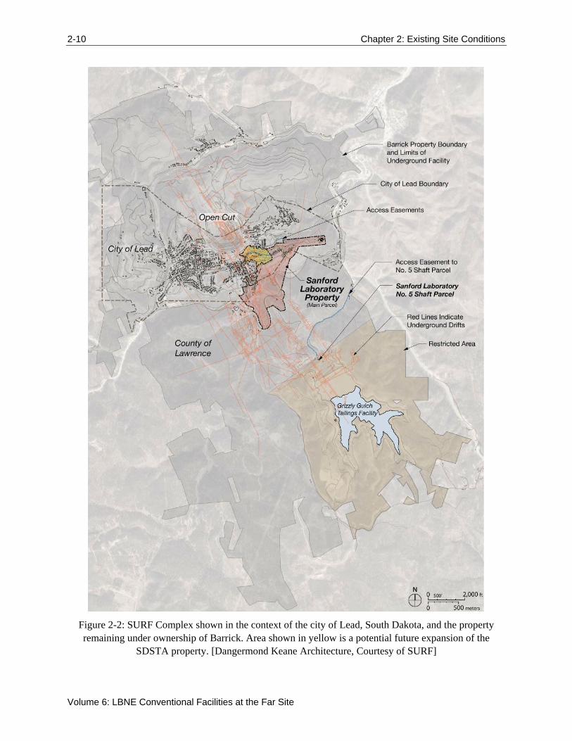
The following figures provide a context for the SURF site. Figure 2-1 illustrates SURF’s location within the region as a part of the northern Black Hills of South Dakota. Figure 2-2 outlines the SURF site in relationship to the city of Lead, South Dakota, and points out various significant features of Lead including the surrounding property that still remains under the ownership of Barrick Gold Corporation1. Figure 2-3 and Figure 2-4 provide perspectives of the SURF Complex from a surface and aerial view of the property and its surroundings. Figure 1-1 shows the location of the 10-kT LAr-FD that will be constructed at the surface. The views in these figures illustrate the varied topography found throughout the area.
1 Barrick Gold Corporation (Barrick) operated the former Homestake Gold Mine in Lead, SD and when they closed the mine operations, a portion of the land was donated to the state of South Dakota and the use of the property is governed by the Property Donation Agreement (PDA) between Barrick and the state of South Dakota. The state of South Dakota manages the development of the SURF site through the SDSTA.

Chapter 2: Existing Site Conditions 2-9
LBNE Conceptual Design Report
Figure 2-1: Regional Context showing the city of Lead, South Dakota. [Dangermond Keane Architecture, Courtesy SURF]
2-10 Chapter 2: Existing Site Conditions
Volume 6: LBNE Conventional Facilities at the Far Site
Figure 2-2: SURF Complex shown in the context of the city of Lead, South Dakota, and the property remaining under ownership of Barrick. Area shown in yellow is a potential future expansion of the
SDSTA property. [Dangermond Keane Architecture, Courtesy of SURF]

Chapter 2: Existing Site Conditions 2-11
LBNE Conceptual Design Report
Figure 2-3: SURF Yates Campus shown on the left and Kirk Canyon to the right. [Courtesy of SURF]
Figure 2-4: Aerial view of SURF (boundary in red) and the adjacent city of Lead. [Dangermond Keane Architecture, Courtesy of SURF]

2-12 Chapter 2: Existing Site Conditions
Volume 6: LBNE Conventional Facilities at the Far Site
2.1 Existing Site Conditions
The existing facility conditions were assessed as part of the DUSEL Preliminary Design and documented in the DUSEL PDR, Section 5.2.4, which is excerpted below. The portions of DUSEL’s assessment included here have been edited to reflect current activities and to reference only that portion of the assessment that are pertinent to the LBNE Project. References to the DUSEL Project are from that time, and are now considered historic.
2.1.1 Existing Facilities and Site Assessment
Site and facility assessments were performed during DUSEL’s Preliminary Design phase by HDR to evaluate the condition of existing facilities and structures on the Yates, and Ross Campuses. The assessments reviewed the condition of buildings proposed for continuing present use, new use, or potential demolition. Building assessments were performed in the categories of architectural, structural, mechanical/electrical/plumbing (MEP), civil, environmental, and historic. Site assessments looked at the categories that included civil, landscape, environmental, and historic. Facility-wide utilities such as electrical, steam distribution lines, water, and sewer systems were also assessed. The assessment evaluation was completed in three phases. The detailed reports are included in the appendices of the DUSEL PDR as noted and are titled:
Phase I Report, Site Assessment for Surface Facilities and Campus Infrastructure to Support Laboratory Construction and Operations (DUSEL PDR Appendix 5.E)
Phase II Site and Surface Facility Assessment Project Report (DUSEL PDR Appendix 5.F)
Phase II Roof Framing Assessment (DUSEL PDR Appendix 5.G)
The site and facility assessments outlined above were performed during DUSEL’s Preliminary Design as listed above and include a review of the following (independent of LBNE’s Far Site scope of work):
Buildings proposed for reuse were evaluated for preliminary architectural and full structural, environmental, and historic assessments.
Buildings proposed for demolition were evaluated for preliminary historic assessments.
Preliminary MEP assessments were performed on the Ross Substation, #5 Shaft fan, Oro Hondo fan, Oro Hondo substation, and general site utilities for the Ross, Yates, and Ellison Campuses.
The Waste Water Treatment Plant (WWTP) received preliminary architectural and structural assessments and a full MEP assessment.
Preliminary civil assessments of the Kirk Portal site and Kirk to Ross access road were also completed.
2.1.1.1 Building Assessment Results
Results of the building assessment work, as detailed in the three reports referenced above, show that the buildings on the Ross and Yates Campuses were architecturally and structurally suitable for reuse or continued use with some upgrades or modifications.

Chapter 2: Existing Site Conditions 2-13
LBNE Conceptual Design Report
2.1.1.2 Site Civil Assessment
Results of the civil assessment found in the Phase I Report, Site Assessment for Surface Facilities and Campus Infrastructure to Support Laboratory Construction and Operations (DUSEL PDR Appendix 5.E) and Phase II Site and Facility Assessment, Project Report (DUSEL PDR Appendix 5.F) showed the following results:
Water and sewer utilities on both the Ross and Yates Campuses need replacement.
Roadway and parking lot surfaces need replacement and regrading. Drainage ways and steep slopes need maintenance.
Retaining walls and transportation structures are in useable condition, with some maintenance, except for two failing retaining walls.
Retaining walls and transportation structures need maintenance in the form of drainage improvements and minor repairs to section loss due to rust and erosion.
Existing fencing and guardrails are a very inconsistent pattern of chain link, wood, and steel; much of the fencing is deteriorating or collapsed.
Abandoned equipment/scrap-metal piles around the sites represent traffic and health hazards.
Pedestrian and traffic separation is poorly defined.
Existing traffic signs are faded and do not meet Manual of Uniform Traffic Control Devices (MUTCD) standards.
The civil site assessment recommendations can be found in DUSEL PDR Appendix 5.E (Section 4, Page 4(1) of the Phase I Report, Site Assessment for Surface Facilities and Campus Infrastructure to Support Laboratory Construction and Operations); and DUSEL PDR Appendix 5.F (Section 2, Page (2.1) – 39 of the Phase II Site and Facility Assessment Project Report). All items that could cause immediate concern regarding the health and safety of on-site personnel have been addressed by the SDSTA by removing, repairing, or isolating the concerns.
2.1.1.3 Landscape Assessment
The landscape assessment, found in DUSEL PDR Appendix 5.E (Phase I Report, Site Assessment for Surface Facilities and Campus Infrastructure to Support Laboratory Construction and Operations); and DUSEL PDR Appendix 5.F (Phase II Site and Surface Facility Assessment Project Report) noted many of the same items as the site civil assessment: drainage issues, erosion concerns, abandoned equipment, and scrap metal. Soil conditions were noted as well as rock escarpments and soil stability concerns.
2.1.1.4 Site MEP Assessment
The site assessments, detailed in DUSEL PDR Appendix 5.E (Phase I Report, Site Assessment for Surface Facilities and Campus Infrastructure to Support Laboratory Construction and Operations); and DUSEL PDR Appendix 5.F (Phase II Site and Surface Facility Assessment Project Report) describes the electrical distribution condition as ranging from fair to excellent, depending on the age of the equipment.

2-14 Chapter 2: Existing Site Conditions
Volume 6: LBNE Conventional Facilities at the Far Site
The Oro Hondo substation is a 20-mVA installed capacity substation intended for supply to the LAr-FD. This substation was built in the mid-1990’s and is situated near the utility provider’s (Black Hills Power) 69-kV switch yard. A 12-kV transformer and switchgear was added to this substation in 2009, and approximately 15 kVA is currently available for expansion, as well as spare 12-kV vacuum circuit breakers. The site is secured with a gated and locked access road as well as gated and locked perimeter fencing and a locked climate controlled building within the perimeter fencing. The drawbacks of this site are that it is situated adjacent to heavily wooded areas on all sides and the site is difficult to access when there are heavy snowfalls in the area.
The assessments also evaluated the natural gas and steam distribution systems. Natural gas is provided to the site at three locations and appears to have the capacity required to meet surface needs as they are currently understood. However, the natural gas supply is an interruptible supply (non-firm) and thus cannot be guaranteed. Either an upgrade to Montana-Dakota Utilities (MDU, local natural gas supplier) supply lines (outside the scope of this Project) or an alternate fuel/heating source will be needed to meet the surface needs. The steam boiler systems have been dismantled and should not be reused. The existing components represent placeholders for routing for new distribution if a steam system is re-employed.
The site telecommunications service currently is provided by Knology Inc., Rapid City, South Dakota, and a fiber-optic data connection is from the South Dakota Research, Education and Economic Development (REED) Network (see DUSEL PDR Chapter 5.5, Cyberinfrastructure Systems Design, for details on these service providers). Both services are quite new and have historically been very reliable. The site distribution system is a mix of copper and fiber, copper being quite old and fiber very new. The Ross and Yates Campus’ recommendations are to increase reliability as the campuses are developed.
2.1.1.5 Environmental Assessment
The environmental assessment, found in DUSEL PDR Appendix 5.F (Phase II Site and Surface Facility Assessment Project Report) looked for contamination from lead-based paint (LBP); polychlorinated biphenyls (PCBs) contained in electrical equipment, lubrication oils, and hydraulics; asbestos-containing building materials (ACBMs); heavy metals; the historic presence of petroleum hydrocarbons and chlorinated solvents; molds; historic uncontrolled discharges of domestic sewage; industrial wastewater; and storm-water runoff. Environmental results showed some LBPs in various locations across both the Ross and Yates Campuses. No PCB concentrations above Environmental Protection Agency (EPA) regulatory standards were encountered, and no heavy metals above EPA regulatory standards were found.
2.1.1.6 Historic Assessment
The former Homestake Gold Mine site is a major component of the Lead Historic District. Most of the SURF Complex is within the historic district; thus, work at the SURF site must conform to the National Historic Preservation Act of 1966, as Amended. These standards recognize that historic buildings and sites must change with time if they are to meet contemporary needs but that alterations to meet these needs can be done in a manner that is sensitive to the historic property. Figure 2-5 is a historic photograph showing the former Homestake Mining Company milling operation and components of the Yates Campus. Figure 2-6 shows the boundaries of the Lead historic district. The proposed site for LBNE experiments at SURF are outside of the designated Historic District.

Chapter 2: Existing Site Conditions 2-15
LBNE Conceptual Design Report
Figure 2-5: Historic photo of milling operation, Yates Headframe, Hoist, and Foundry. [Courtesy Homestake Adams Research and Cultural Center]
The historic assessment consisted of the full assessment of 10 transcendent and eight support buildings. Transcendent buildings have the most significant historic value and represent an operation that was unique or limited to the site. Support buildings represented a function or activity that, although performed on the site, could have been done off site. Of the 10 transcendent buildings, nine were deemed to have significant historic value while one held only moderate historic value. Seven of the support buildings held moderate historic value, while the eighth has only limited historic value. Sixteen other buildings received a preliminary historic assessment. Two were deemed to have significant historic value, 13 held moderate historic value, and the last was deemed to be of limited historic value.
To assist the DUSEL project in understanding the historic requirements for the Project, a meeting was held with the South Dakota State Historic Preservation Office (SD SHPO) in June 2010. The DUSEL team provided a project overview for the SD SHPO staff and took a site tour so the SHPO staff could develop an understanding of the project. The SD SHPO staff members were pleased, for the most part, with the direction the design team was taking for the Project. SD SHPO provided recommendations to DUSEL for documentation and preservation options that will need to be addressed during Final Design to meet mitigation requirements for any facilities that may ultimately be removed. LBNE is not currently planning to remove any existing structures.
It should be noted that the historic assessment prepared for this portion of the overall site assessment is not the formal historic assessment that will be required to comply with the National Environmental Policy

2-16 Chapter 2: Existing Site Conditions
Volume 6: LBNE Conventional Facilities at the Far Site
Act (NEPA) strategy. See section 3.1.1of this volume for additional information about the LBNE NEPA strategy.2
The entire historic assessment process and results can be viewed in DUSEL PDR Appendix 5.E (Phase I Report, Site Assessment for Surface Facilities and Campus Infrastructure to Support Laboratory Construction and Operations), and DUSEL PDR Appendix 5.F (Phase II Site and Surface Facility Assessment Project Report).
Figure 2-6: Map of Lead Historic District. [Dangermond Keane Architecture, Courtesy of SURF]
2.2 Geology and Existing Excavations
LBNE Far Site facilities are planned to be constructed at SURF which is being developed within the footprint of the former Homestake Gold Mine, located in Lead, South Dakota. The accessible underground mine workings are extensive. Over the life of the former gold mine some 360 miles of drifts (tunnels) were mined and shafts and winzes sunk to gain access to depths in excess of 8,000 feet. Under separate funding, a number of underground workings are being refurbished by SURF and new
2 For clarity, this discussion of NEPA activities was developed for this Conceptual Design Report and inserted into this section of text which is largely copied from the DUSEL Preliminary Design Report. Discussions on NEPA were not included in the text of the DUSEL Preliminary Design Report. LBNE specific NEPA discussions have begun.

Chapter 2: Existing Site Conditions 2-17
LBNE Conceptual Design Report
experiments are being developed at the 4850L. Geotechnical investigations and initial geotechnical analyses were completed for the DUSEL Preliminary Design and are described in detail in the DUSEL PDR. Below are summaries of some of the work completed to date that is applicable to LBNE as excerpted from the DUSEL PDR, Chapter 5.3, and edited to include only information as it is relevant to the development of the LBNE Project. Much of the work completed was for an alternate detector technology that was considered by LBNE (water Cherenkov detector [WCD]), but provides regional information applicable to the current reference design.
2.2.1 Geologic Setting
SURF is sited within a metamorphic complex containing the Poorman, Homestake, Ellison, Northwestern, Flagrock and Grizzly Formations (oldest to youngest), which are sedimentary and volcanic in origin. The surface location for the detector is projected to be located within the Northwestern and Flagrock Formations.
2.2.2 Rock Mass Characterization
One of the goals of the geotechnical investigations performed to date by the DUSEL project was to provide information for the excavation and stabilization of a large cavity for a WCD supporting the LBNE Project. Characterization of the rock mass (see DUSEL PDR Sections 5.3.2 and 5.3.3) was accomplished through a program of mapping existing drifts and rooms in the vicinity of planned excavations, drilling and geotechnical logging of rock core samples, and laboratory measurements of the properties of those samples. The geotechnical work that was performed for WCD is not directly applicable to LAr-FD at the surface, but does provide some insight into the expected characteristics of the metamorphic complex rock mass in this area.
As part of the Preliminary Design process, the DUSEL project engaged two advisory boards to provide expert review of the geotechnical investigation and excavation design efforts. The Geotechnical Advisory Committee (GAC) was an internal committee that focused primarily on geotechnical investigation and analysis. The Large Cavity Advisory Board (LCAB) was an internal high-level board that focused on geotechnical investigations and excavation design of the WCD cavity in support of the LBNE Project, much of which is applicable to LAr-FD at the surface. The geotechnical engineering services contract for initial geotechnical investigations, was reviewed by the GAC and the LCAB and included the following scope of work:
The mapping program included drift mapping at the 300L and 4850L and 4,400 ft (1,340 m) of existing drifts mapped in detail and 2,600 ft (793 m) of newly excavated drifts and large openings mapped in detail (Davis Campus, Transition Area, and associated connecting drifts).
The drilling program included the completion of nine new holes totaling 5,399 ft (1,646 m) of HQ (4-inch) diamond core drilling, which incorporated continuous logging, continuous core orientation, detailed geotechnical and geological logging, full depth continuous televiewer imaging, and initial groundwater monitoring.
The in situ stress measurement program included stress measurements in three locations; two sites in amphibolite and one site in rhyolite for the total of eight measurements (six in amphibolite and two in rhyolite).

2-18 Chapter 2: Existing Site Conditions
Volume 6: LBNE Conventional Facilities at the Far Site
The laboratory testing program included uniaxial compressive strength tests (80 samples that incorporated elastic constants and failure criteria), indirect tensile strength tests (40 samples), triaxial compressive strength tests (63 samples), and direct shear strength of discontinuities (36 samples).
Geotechnical investigations were initiated by DUSEL in January 2009 and executed by RESPEC Inc., with Golder Associates and Lachel Felice & Associates (LFA) as their main subcontractors. The initial scope was modified to include the addition of a 100kT water Cherenkov detector (WCD). The scope was further modified, resulting in the requirement for the potential to include up to two 100kT WCDs into the DUSEL Preliminary Design effort. In mid-2010, the DUSEL Preliminary Design scope was narrowed to one WCD. Subsequently, the project considered locating a LAr detector at the 800L, the 4850L, and on the surface.
The initial geotechnical program was executed by DUSEL first on the 300L (which coincides with the level for the reference scope LAr-FD at surface) and then on the 4850L of the Homestake site. This program included site mapping, reconnaissance level geotechnical drilling and core logging, in situ stress measurements, optical and acoustic televiewer logging, numerical modeling, laboratory testing, initial surveying, and generation of a three dimensional (3D) Geological and Geotechnical Model. Additional tasks added in 2010 included characterization of ground vibrations from blasting associated with the Davis Campus excavation activities, and groundwater monitoring. A Geotechnical Engineering Summary Report (DUSEL PDR Appendix 5.H) was completed in March 2010, which recommended additional drilling and mapping to address data gaps and reduce uncertainty in the characterization of the rock mass that would be important for future phases of design..
Since their formation, the host rock units have been subject to periods of significant structural deformation. Deformations during the Precambrian era lead to the development of complex fold patterns, and local shear zones. Brittle deformations that took place during the Tertiary era resulted in the development of joint sets, veining, faulting and the intrusion of dikes [7]. Tertiary rhyolite dikes cross-cut the Precambrian rock units across the former mine site, from surface (open cut) to the deepest development levels (>8,000 ft). Rhyolite is estimated to constitute some 40% of the country rock volume in the area of the proposed campus. Faulting and veining have also been observed within the host rock mass (Lachel Felice & Associates, Geotechnical Engineering Services Final Report for 4850L Mapping [8], and Golder Associates, LBNE Far Site Detector Excavation Conceptual Design: 4850 Level Liquid Argon (LAr) Reference Design Final Report [9]).
The in situ stress levels at various depths of the SURF underground site have been measured on a number of occasions. For further details, see Golder’s Geotechnical Engineering Services, In Situ Stress Measurement Deep Underground Science and Engineering Laboratory [10]. Based on the results of studies completed for various levels of the site and historically available data, the proposed 10kT LAr surface location is anticipated to have neutral stress conditions.
The intact hard metamorphic rocks are generally of low primary hydrologic conductivity. During historic mine operations most water inflows were observed to be local and typically attributed to secondary permeability [11]. A recent evaluation by Golder [9] estimates the typical inflow rate of about 1 to 2 gallons per minute per mile of underground workings. Some additional flow may be anticipated in the upper workings where fractures may be more weathered, open and directly connected to the surface

Chapter 2: Existing Site Conditions 2-19
LBNE Conceptual Design Report
and/or the Open Cut. Proposed surface site geotechnical investigations will focus on characterizing soil, rock, and groundwater conditions at the LAr-FD surface location.
2.2.3 Geologic Conclusions
The site specific recovery of rock cores, plus geologic mapping, is recommended to be performed for the purpose of characterizing the rock mass and to determine if discontinuities in the rock mass exist that would cause difficulties in the construction and maintenance of planned excavations. In general, the proposed locations of the excavations do not appear to be complicated by geologic structures that could cause undue difficulties for construction. This information, along with existing measurements of local in situ stresses, allows initial numerical evaluation of the stresses associated with the anticipated excavations and preliminary ground support designs.
The overall analysis of the existing geotechnical investigations conducted at depth indicates that the rock in the proposed surface location of the LAr-FD excavation will most likely be of similar good quality for the purposes of the LBNE Project, that a large excavation of the size envisioned can be constructed, and that a workable excavation conceptual design has been developed.
3-20 Chapter 3: The Facility Layout
Volume 6: LBNE Conventional Facilities at the Far Site
3 The Facility Layout
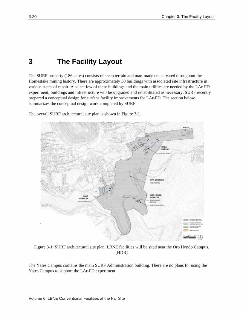
The SURF property (186 acres) consists of steep terrain and man-made cuts created throughout the Homestake mining history. There are approximately 50 buildings with associated site infrastructure in various states of repair. A select few of these buildings and the main utilities are needed by the LAr-FD experiment; buildings and infrastructure will be upgraded and rehabilitated as necessary. SURF recently prepared a conceptual design for surface facility improvements for LAr-FD. The section below summarizes the conceptual design work completed by SURF.
The overall SURF architectural site plan is shown in Figure 3-1.
Figure 3-1: SURF architectural site plan. LBNE facilities will be sited near the Oro Hondo Campus. [HDR]
The Yates Campus contains the main SURF Administration building. There are no plans for using the Yates Campus to support the LAr-FD experiment.

Chapter 3: The Facility Layout 3-21
LBNE Conceptual Design Report
The Ross Campus will house the control room for the LAr-FD experiment, as well as continue to house the SURF maintenance and operations functions. Layout of surface facilities in the vicinity of the Ross Shaft is shown in Figure 3-2.
Figure 3-2: Ross Campus Architectural Site Plan. [HDR]
The existing facilities at the Oro Hondo Campus include three locations: the Oro Hondo substation site; the Oro Hondo adit which provides an underground connection to the Ross Shaft at the 300L; and the Oro Hondo fan site. The fan site includes the Oro Hondo Shaft which serves as the primary underground ventilation exhaust pathway for the all SURF underground spaces. The existing fan site will be modified to allow construction of the LAr-FD adjacent to the existing installation (see Figure 1-1). In addition, the new LAr-FD site will be configured to facilitate cryogen delivery with standard over the road trucks. Layout of surface facilities at the LAr-FD site is shown in Figure 3-3.

3-22 Chapter 3: The Facility Layout
Volume 6: LBNE Conventional Facilities at the Far Site
Figure 3-3: Oro Hondo Campus Site Plan. [HDR]
3.1 Project-Wide Considerations
There are several project-wide considerations, many with environmental aspects that are discussed below.
3.1.1 Environmental Protection
The LBNE Project will prepare designs and execute construction and operations of the LAr-FD at the Far Site in accordance with all codes and standards to ensure adequate protection of the environment. The SURF codes and standards outline the requirements for work at the site.
The overall environmental impact of the LBNE Project will be evaluated and reviewed for conformance to applicable portions of the National Environmental Policy Act (NEPA). Specific environmental concerns will be addressed during the project as described below.
The LAr-FD design will optimize the use of excavated material to produce as much usable space as practical. During excavation and handling, water sprays will be used to minimize dust. Water and/or other dust control methods will be used to control dust from traffic on both Kirk Road and the site access road.

Chapter 3: The Facility Layout 3-23
LBNE Conceptual Design Report
3.1.2 Safeguards and Security
A facilities security system will be installed to provide a secure environment for the interior and the exterior of the experiment-specific facilities and will consist of the following:
Closed Circuit Video Monitoring: A closed circuit video system to monitor security cameras at selected locations
Card Access Control: An electronic access control system utilizing proximity card readers to control and record access to designated doors in the facility
Intrusion Detection Alarms
Security System Integration: The access control and video monitoring system shall be integrated into the SURF security monitoring system and monitored at the control room.
3.1.3 Emergency Shelter Provisions
Guidelines established by the Federal Emergency Management Agency (FEMA) in publications TR-83A and TR-83B and referenced in Section 0111-2.5, DOE 6430.1A, may – if determined to be applicable –be used to assess the design of the buildings to insure safe areas within the buildings for the protection of the occupants. These protected areas would also serve as dual-purpose spaces with regard to protection during a national emergency in accordance with the direction given in Section 0110-10, DOE 6430.1A.
FEMA guidelines indicate that protected areas are:
On the lowest floor of a surface building
In an interior space, avoiding spaces with glass partitions
Areas with short spans of the floor or roof structure are best; small rooms are usually safe, large rooms are to be avoided.
3.1.4 Energy Conservation
The DOE directive, Guiding Principles of High-Performance Building Design, will be incorporated into the design of the LBNE Conventional Facilities. However, discussions are ongoing regarding the applicability of the guiding principles based on the type and use of the facilities. LBNE processes and each Project element will be evaluated during design to reduce their impact on natural resources without sacrificing program objectives. The Project design will incorporate maintainability, aesthetics, environmental justice, and program requirements as required to deliver a well-balanced project.
All elements of this Project will be reviewed for energy conservation features that can be effectively incorporated into the overall building design. Energy conservation techniques and high efficiency equipment will be utilized wherever appropriate to minimize the total energy consumption. See DOE Guiding Principles for Sustainable Design and Construction [12].

3-24 Chapter 3: The Facility Layout
Volume 6: LBNE Conventional Facilities at the Far Site
3.1.5 DOE Space Allocation
The elimination of excess facility capacity is an ongoing effort at all DOE programs. Eliminating excess facilities (buildings) to offset new building construction (on a building square foot basis) frees up future budget resources for maintaining and recapitalizing DOE’s remaining facilities.
The LBNE Near Site portion of the Project has obtained a DOE Space Allocation/Space Bank waiver, meaning that there is sufficient elimination of excess structures elsewhere in DOE facilities to offset the proposed LBNE building square footage.
3.2 Sitework and Site Infrastructure (WBS 130.06.03.05.02.01)
The primary excavated spaces necessary to support the LAr-FD experiment include a combination of cut and fill – prepare a level site of sufficient area for the detector and supporting buildings – and the excavation of the Detector Pit. The cut and fill analysis for conceptual design was performed by Albertson Engineering and HDR, both architecture and engineering firms have South Dakota offices familiar with excavations in the Black Hills. For the Detector Pit excavation, the design and budget are assumed to be similar to Fermilab’s NOvA Project in Ash River, MN. The project elements and geotechnical characteristics of the rock types at both sites are comparable enough to make this assumption valid for the conceptual design level.
3.2.1 Site Preparation
3.2.1.1 Roads and Access
The LAr-FD site is accessible via Kirk Road, a county owned and maintained gravel road designed to meet state and county standards for load capacity and clearances. Kirk Road is accessible from two federal highways, US Highway 385 at one end and US Highway 85 at the other end. From Kirk Road, the site is accessed via a privately-owned and maintained road that extends to the Grizzly Gulch Tailings Dam (a legacy dam used during mining at the site that is maintained by Barrick). The existing condition of this road is not suitable for truck access; this road will be improved and paved from Kirk Road to the LAr-FD site. Access beyond the LBNE site must be maintained for both Barrick and Black Hills Power (the local electrical utility provider).
The reconfigured road will be diverted around the detector site and re-join the existing road a short distance beyond the site. An 8-10% grade will be maintained along all sections of road impacted by the LAr-FD construction to maintain the shared access requirements. The existing road beyond the the site (where the reconfigured road re-joins the existing road) will remain in a similar condition (gravel) to the existing road and will not be improved as part of the scope of this Project, except to repair any damage caused by the LAr-FD construction. Relocation of this road will require that SURF acquire a small (~3 acre) area parcel of land adjacent to the LAr-FD site from Barrick Corporation; conversations with Barrick to date have assured that this will not be an issue.

Chapter 3: The Facility Layout 3-25
LBNE Conceptual Design Report
The road is currently only used for access to utility power lines, a SURF substation, and Grizzly Gulch tailing Dam. Access to these facilities will also be available along a secondary route during construction, but must be restored to this primary route following construction.
3.2.1.2 Cut and Fill
The location of LAr-FD was selected due to the ability to provide coverage at a 70° azimuth (20° up from horizontal) in the direction of the LBNE neutrino beamline shielding from low angle muons on trajectories generally parallel to the LBNE neutrino beam line. A graphical depiction of this is shown in Figure 3-4. This coverage provides shielding to ensure neutrinos detected from the beam are not confused with solar neutrinos. The selected site also has the benefit of having existing roads that pass both above and below as described in the previous section. Some disadvantages of the site include the steep terrain and the interruption of a natural drainage path of a nearby valley. To address these disadvantages, the first phase of construction includes preparing a flat level site and redirecting the natural water flows through the site.
Figure 3-4: LAr-FD coverage at 20° from horizontal in beam line direction. [HDR]
Preparation of a level site requires a substantial cut into the existing hillside, with the installation of a rock anchor wall with a shotcrete finish in the Detector Pit to provide ground stability during construction. As described above, the existing road will be relocated immediately uphill of this wall. Maximizing the available site footprint to provide adequate space for the buildings and truck access requires shorter retaining walls for portions of the wall on all sides of the site. These walls will be a combination of concrete block and rock anchor walls depending on height and whether the area is a cut or fill section. Guard rails will be installed at the lower edge of the site and fencing will be installed on all accessible sides. Figure 3-5 shows the site plan with the retaining walls described, as well as the pit excavation described in the next section.

3-26 Chapter 3: The Facility Layout
Volume 6: LBNE Conventional Facilities at the Far Site
Figure 3-5: Retaining walls and site layout. [HDR]
Approximately 65,000 cubic yards of material must be excavated from the hillsides surrounding the area, with ~27,000 cubic yards of this material used for fill to level the site. The secondary access road described in Section 3.2.1.1 above will be developed using this fill to connect the LBNE site to the existing Oro Hondo fan site. A portion of the remaining fill will be utilized as shielding cover for the detector. The balance of the material will be placed uphill of the site to create an additional flat site that may be used for future development. Figure 3-6 shows the proposed disposal location for excess material (waste rock) which is accessible via the existing Grizzly Gulch Road. This has been described to the state of South Dakota and they do not anticipate the need for solid waste permitting for rock removed at the surface and disposed at the surface.

Chapter 3: The Facility Layout 3-27
LBNE Conceptual Design Report
Figure 3-6: Waste Rock Disposal Area. [HDR]
3.2.2 Infrastructure
Surface infrastructure includes surface structures –such as retaining walls and parking lots – as well as utilities to service both buildings and underground areas. Existing infrastructure requires rehabilitation and upgrades to meet both code requirements and LAr-FD experiment needs. The LAr-FD experiment needs that define the Conventional Facility requirements are documented in the LBNE Requirements Document [13].
With the exception of power and propane gas, all LAr-FD utility infrastructure will be conveyed underground from the 300L of the Ross Shaft, through the 300L Oro Hondo adit to the surface, and then buried near grade to the LAr-FD site. Cyberinfrastructure will also be conveyed down the Ross Shaft. Power will be conveyed from the Oro Hondo substation site and propane gas will be provided by truck to an on-site storage tank.
3.2.2.1 Electrical Infrastructure
Power for the experiment and new facilities will be fed from the Oro Hondo substation which is located approximately 600 ft from the proposed LAr-FD site. Power for life safety loads, primarily lighting and ventilation, will be powered by an on-site generator (sized to meet the required life safety system loads). Emergency power, defined by National Fire Protection Association (NFPA) codes as “critical for life

3-28 Chapter 3: The Facility Layout
Volume 6: LBNE Conventional Facilities at the Far Site
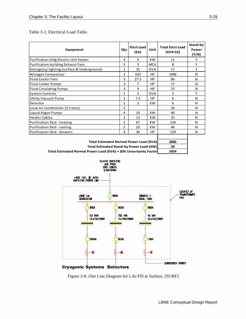
support” will be provided by 90-minute battery-backed uninterruptible power supply (UPS) connected downstream of the standby power system. Figure 3-7 indicates the location of electrical infrastructure work at the LAr-FD site. Power requirements for the LAr-FD experiment and facility are shown in Table 3-1. A single line diagram of the equipment provided for electrical supply to LAr-FD is shown in Figure 3-8.
Figure 3-7: Supply Power for LAr-FD at Surface. [HDR]
Chapter 3: The Facility Layout 3-29
LBNE Conceptual Design Report
Table 3-1: Electrical Load Table.
Equipment QtyElect Load
(EA)Unit
Total Elect Load
(KVA EA)
Stand‐by
Power
(Y/N)
Purification bldg Electric Unit heater 4 5 KW 11 Y
Purification building Exhaust Fans 3 3 MCA 8 Y
Emergency lighting (surface & Underground) 1 15 KVA 17 Y
Nitrogen Compressor 3 623 HP 1496 N
Fluid Cooler Fans 3 27.5 HP 66 N
Fluid Cooler Pumps 3 7 HP 17 N
Fluid Circulating Pumps 3 9 HP 22 N
System Controls 1 3 KVA 3 Y
Utility Vacuum Pump 1 7.5 HP 6 N
Detector 2 3 KW 6 N
Local Air Conditioner (2.5 tons) 2 20 N
Liquid Argon Pumps 4 10 KW 40 N
Heater Cables 2 13 KW 25 N
Purification Skid ‐ heating 2 67 KW 134 N
Purification Skid ‐ cooling 2 23 KW 46 N
Purification Skid ‐ blowers 4 30 HP 129 N
2006
39
2454
Total Estimated Normal Power Load (KVA)
Total Estimated Stand‐by Power Load (KW)
Total Estimated Normal Power Load (KVA) + 20% Uncertainty Factor
Figure 3-8: One Line Diagram for LAr-FD at Surface. [SURF]

3-30 Chapter 3: The Facility Layout
Volume 6: LBNE Conventional Facilities at the Far Site
3.2.2.1.1 Normal Power
The electrical systems are designed to meet International Building Code (IBC) and applicable portions of the National Electric Code (NEC) and National Electric Safety Code (NESC).
The LAr-FD experiment equipment will have a dedicated shielded transformer to serve the detector electronics at 208V/120V. In addition, LAr-FD mechanical equipment will be fed from a dedicated transformer. Within the Detector Hall, electrical panels and small transformers will serve equipment operating in the LAr-FD Detector Hall and pit. High voltage equipment and cables will be located away from the detector to meet the experiment electrical noise requirements.
3.2.2.1.2 Standby Power
A generator set, located on the surface near the detector will be installed to provide standby power for life safety. Emergency lights, exit signs, fire alarm, security, and IT System for communications will all be supplied by the standby power system.
3.2.2.2 Fire Alarm and Detection
All occupied spaces for the LAr-FD will have notification devices installed to alarm the occupants of an emergency condition. Notification devices will consist of speakers and strobe lights. Manual pull stations will be provided within 200 ft of egress. Phones will be installed in the Detector Hall and in the other permanent buildings within this scope.
An air sampling and gas detection system will be installed in the Detector Hall and supporting buildings as an early detection of a potentially hazardous condition. The air sampling system will be connected into the fire alarm system.
The fire alarm system will also interface with the Oxygen Deficiency Hazard (ODH) system to initiate an alarm at the respective fire alarm panel and at the control room (located at the Ross Dry). Specific sounds and strobe colors will be identified based on the type of alarm (fire, ODH, etc.).
3.2.2.3 Lighting
Suspended lights mounted at a height just below the lowest obstruction will be provided for all buildings. Mounting will be coordinated with conduit and supports of other systems running overhead. Maintained average illumination of approximately 24 lux (2.4 foot candles) at floor level will be provided throughout.
Lighting within equipment rooms will be UL Wet Location rated, watertight fluorescent fixtures. Exact layouts will be coordinated with final equipment at future design stages. Lighting control in equipment rooms will be via switch only, avoiding possibility of unexpected lights-off triggers.
All light fixtures within the Detector Hall will be incandescent light fixtures to minimize Electromagnetic Interference (EMI) near the experiment. Average luminance levels at 0.7m above the liquid argon vessel roof will be between 100 and 150 lux (10-15 foot candles). All light fixtures will be controlled through a networked lighting control system allowing switching of multiple zones or circuits from multiple locations, and time schedule or other automated functions. Emergency light fixtures will be provided with 90-minute battery backup from a centralized system.

Chapter 3: The Facility Layout 3-31
LBNE Conceptual Design Report
3.2.2.4 Grounding
The grounding system will be designed to provide effective grounding to enable protective devices to operate within a specified time during fault conditions, and to limit touch voltage under such conditions. The grounding system will be designed for a maximum resistance of 5 ohms where possible. Ground beds, consisting of an array of ground rods, will be installed at the substation to provide low impedance to ground.
Main ground bars will be installed in all substations. All extraneous conducting metal work will be bonded. A dedicated grounding cable will be distributed from the respective substation ground bus to the LAr-FD Detector Hall and from there to individual items of equipment and distribution boards.
A saturable inductor will be installed to mitigate common mode noise at the transformers dedicated to the LAr-FD detector electronics. An Ufer grounding system will be provided by grounding the rebar within the liquid argon Detector Pit to rock bolts which will be connected into the main grounding system. The Ufer grounding system will be connected to the main ground bus at the substation.
3.2.2.5 Cyberinfrastructure
On the overall site, communications infrastructure is required for voice/data communications, security, facility management system, and fire alarm system. The campus fiber and copper backbone network will be upgraded by SURF and extended to the existing Ross Hoist Building telecommunications closet. Connections will include connection to the Ross Dry control room and to the LAr-FD site. Supply to the detector site will pass down the Ross Shaft to the 300L. At the 300L of the Ross Shaft, the fiber optic cable will follow an existing horizontal drift, out of the Oro Hondo Adit to the ground surface, and pass by the Oro Hondo substation overland to get to the LAr-FD site. This route is partially shown in Figure 3-7 above.
A fiber optic backbone provides communications for voice, data, and control of all systems. Voice communications are provided via two-way radios and phones distributed throughout the site. Two-way radios are effective across the site and to the Ross Dry, as there is a clear line of site between the detector site and this existing Ross Dry building. Phones utilize Voice over Internet Protocol (VoIP) to provide communication though the fiber optic data backbone.
The data system is designed to provide 10-Gigabit Ethernet in the backbone and 1-Gigabit Ethernet to connected systems (computers). This system is intentionally left at a lesser level of design due to the continuous progression and advancement of technology that will almost certainly result in more advanced technologies than are currently available being utilized at the time of construction.
A control room at the Ross Dry building will be the primary location for Human Machine Interface (HMI) with the control system for both the detector hall mechanical and electrical systems and the experiment. This room will also provide a central location for any security systems identified by either SURF or LBNE later in the design process. These systems may include video monitoring, asset tracking, etc. The fire alarm and control system will be an isolated system from the remainder of the cyberinfrastructure to ensure reliability of this system independent of the control system. This system will also be monitored from within the control room.
3-32 Chapter 3: The Facility Layout
Volume 6: LBNE Conventional Facilities at the Far Site
3.2.2.6 Mechanical and HVAC
Heating, ventilation, and air conditioning (HVAC) systems for the LAr-FD are included as part of each building package with individual air handling systems dedicated to each building. For conceptual design, the primary HVAC system for the Detector Hall is based on the design implemented for Fermilab’s NOvA Project in Ash River, MN. This design used several air handling units to provide a level of redundancy. Temperature control of the Detector Hall needs to be in the range of 50° to 82° F with a dew point no higher than 48° F. The dew point requirement is necessary to prevent condensation within locally cooled, rack mounted electronics. The temperature control of the cryogenic equipment building and purification equipment building is less stringent, in the range of 40° to 104° F with no humidity requirement.
3.2.2.7 Plumbing Systems
The existing Oro Hondo Campus does not have a water supply. Water for LAr-FD is only required for process equipment and fire protection. To provide for these requirements, a new 8-inch water main will be provided. The water main will connect to an existing main within the Ross Shaft, travel through the existing drift and Oro Hondo Adit at the 300L where it will surface, cross an existing utility bridge over Kirk Road and follow the natural land contours in a trench to the LAr-FD site. This path from the Oro Hondo Adit to the LAr-FD detector site is shown in Figure 3-9 below.
Water discharges from the site should be minimal and restricted to condensation from the cryogenic systems, HVAC system, and sump discharges capturing natural water flows surrounding the Detector Pit. This water will need to be tested periodically to ensure environmental compliance before discharge into the nearby Oro Hondo Shaft, where it will ultimately mix with the underground pool and be pumped through the existing waste water treatment maintained by the SURF.

Chapter 3: The Facility Layout 3-33
LBNE Conceptual Design Report
Figure 3-9: Oro Hondo Campus Water Main path shown in blue. [HDR]
3.2.2.8 Fire Protection Systems
The only existing building that is planned for use by LAr-FD is the Ross Dry building where the LAr-FD control room will be located. The areas impacted by LAr-FD will be fully sprinklered. The fire protection system for the existing buildings will be supplied from the water distribution system on site. The system will be designed in accordance with NFPA‐13 guidelines, with fire sprinkler hazard classifications selected to suit the building function. All new buildings will also be provided with full sprinkler coverage as required by code. Piping for the sprinkler and standpipe systems will be Schedule 40 black steel with flanged, grooved or threaded fittings.
3.2.2.9 Gas Fuel System
Liquid Propane (LP) gas will be used as the primary fuel for heat at the LAr-FD detector site. The existing natural gas supply in this area is not sufficient to meet the required loads, and the distance to connect to a larger supply is cost prohibitive. A single 12,000-gallon propane storage tank (filled with propane from a delivery truck) will be placed on the site at a location to be determined during Preliminary Design and will be used for fuel supply. The primary design criteria for the fuel distribution system will

3-34 Chapter 3: The Facility Layout
Volume 6: LBNE Conventional Facilities at the Far Site
use the 2009 International Plumbing Code and NFPA‐54, including the applicable state and city amendments.
Propane will be distributed within buildings in Schedule 40 black steel piping with black iron welded fittings. The propane lines serving the facility will be sized for the current building program with an additional anticipated load of 20% for renovation flexibility.
3.2.2.10 Site Drainage
Surface drainage of the detector site is an important part of the reference design, as the construction at this location will interrupt an existing natural drainage path for the areas at elevations higher than the detector. The design for controlling these water flows is based on analysis of the 100-year flood event and requires a 48-in drainage pipe to redirect water from the higher elevations and restore it to the natural (existing) flow path as shown in Figure 3-10. An analysis was performed to define the 100-year flood plain which determined that the detector site is 30-40 feet above the 100-year flood level of White Wood Creek (see Figure 3-11) [14].
Figure 3-10: Site plan showing storm sewer path. Storm sewer route is shown in red with the storm sewer inlet on the left side of the site (higher elevation), re-routing below grade around the Detector Pit, and discharging the storm water on the lower side of the site retaining wall on the right side of the plan.
[HDR]

Chapter 3: The Facility Layout 3-35
LBNE Conceptual Design Report
Figure 3-11: 100-year flood plain for White Wood Creek showing the relative position to the detector site. [HDR]
3.2.2.11 Other Drainage
The detector site is not anticipated to be regularly occupied during operation. As office or work areas are not planned, restroom facilities will be minimized by using portable units. The limited amount of water used (equipment cooling) and generated onsite (condensation from space cooling and cryogenic cooling) is not expected to be contaminated and will be captured for testing before being discharged to the Oro Hondo shaft as described in Section 3.2.2.7.
3.3 Service, Support Buildings and Outfitting (WBS 130.06.03.05.02.02)
Existing surface facilities utilized for the LAr-FD include spaces for temporary offices (provided by SURF), temporary warehousing of experiment installation parts and equipment, a small 400-sf control room, and the buildings required for the experiment itself. The permanent control room for LAr-FD will be located in the existing Ross Dry which will be rehabilitated to be code-compliant and to provide for the needs of the experiment. New support structures for the experiment will be constructed by LBNE including a Cryogenic Equipment Building, a Purification Building, and the Detector Hall and will be located on the LAr-FD site as shown in Figure 3-10. Temporary office space will be located within

3-36 Chapter 3: The Facility Layout
Volume 6: LBNE Conventional Facilities at the Far Site
existing structures on the Ross Campus and a location for the temporary warehouse will be determined during preliminary design.
3.3.1 Ross Dry
The Ross Dry building is in use by SURF to provide office and meeting space in addition to men’s and women’s dry facilities. A portion of an existing meeting space within this building will be modified to allow the installation of a control room for both facility and experiment control.
The exterior of the Ross Dry is shown in Figure 3-12. The location of the new LAr-FD control room within the Ross Dry is shown in Figure 3-13.
Figure 3-12: Photo of Ross Dry Exterior. [HDR]
Figure 3-13: Location of the new LAr-FD control room within the Ross Dry. For orientation, the lower right corner of this plan corresponds with corner of the building visible in Figure 3-12. Note that this
figure was created for an alternate configuration; the LAr 4850L Control Room is in the same location as the LAr-FD control room. [HDR]

Chapter 3: The Facility Layout 3-37
LBNE Conceptual Design Report
3.3.2 Temporary Warehouse and Office Space
LAr-FD experiment requires 4,000 sf of temporary warehouse space to support experiment installation which will be provided by LBNE at a location yet to be determined. SURF will also provide some temporary office space to the LAr-FD experiment within existing facilities onsite at no cost to the LBNE Project.
3.3.3 Detector Site Buildings
Three new buildings are required to house the detector and equipment that maintains the argon used in the detector in liquid form. These buildings are shown in Figure 3-14, and include the Detector Hall, Cryogenic Equipment Building, and a Purification Building. The support buildings (cryogenic and purification) are described in detail in the following sections. The Detector Hall is described in Section 3.5.
Figure 3-14: Site Buildings. [HDR]
3.3.4 Cryogenic Equipment Building
The Cryogenic Equipment Building houses the equipment necessary to provide cryogenic refrigeration of the liquid argon of the LAr-FD. The equipment includes several compressors and heat exchangers and gas expanders. All of the electrical systems required to support the cryogenic equipment is contained within this building. The building is a 3,640 sf (338 m2) steel-frame construction with a thickened concrete foundation and additional foundations that are specific to the equipment. Significant heat will be generated by the cryogenic equipment operating in the building, so the ventilation system will be designed to maintain limited temperature fluctuations for equipment efficiency. The building is also

3-38 Chapter 3: The Facility Layout
Volume 6: LBNE Conventional Facilities at the Far Site
insulated for both thermal loss and noise control. While the site is isolated from residential areas by a minimum of 1,700 ft (518 m), a publically-accessible and often-used recreation path passes within 350 ft (107 m) of the site. To ensure compliance with noise pollution standards, the design will maintain a maximum sound level at the site boundary of 45 dBA.
3.3.5 Purification Building
The Purification Building houses the equipment necessary to maintain the argon purity. This includes a mole sieve filtration system with a corresponding regeneration system for the filter. All of the electrical equipment required to support the purification equipment is contained within this building. The building is a 3,000 sf (279 m2) steel frame construction building with a thickened concrete foundation and additional foundations specific to the equipment. Liquid argon is present in this building, so the ventilation system will be designed to ensure personnel safety with adequate fresh air supply to prevent oxygen deficiency hazards. The building is insulated for both thermal loss and noise control similar to the Cryogenic Equipment Building.
3.3.6 Fill Station
The fill station is primarily used for cryogenic liquid deliveries of both argon and nitrogen. A 1,800-sf (167-m2) concrete pad will provide a site for several vertical LAr and liquid nitrogen dewars.
3.3.7 Other structures
In addition to what is described above, a variety of minor structures are required in addition to these buildings. Several retaining walls are required on the site to manage the steep (~20°) natural terrain of the site. An existing bridge crossing Kirk road will be utilized to support the water supply and other utilities to the detector site. A small concrete pad will be required for installation of both the primary transformer and the standby generator.
3.4 LAr Excavation and Pit Construction (WBS 130.06.03.05.03.01)
The requirements for the experimental spaces were defined through interaction with the LAr-FD design team and are documented in the LBNE Requirements Document [13]. The size of the LAr-FD detector pit was defined to meet the scientific needs of the experiment. A cross section of the LAr-FD taken parallel to the neutrino beam line is shown in Figure 3-15. A cross section taken perpendicular to the neutrino beam line is shown in
Figure 3-16. Note that the Detector Pit will be a large excavation of rock at the surface nestled into the hillside to provide shielding from low-angle solar muons in the direction of the LBNE neutrino beam line. The top and sides of the LAr-FD Detector Pit must be shielded by at least 3 m of material having a density of at least 2.7 g/cm3.

Chapter 3: The Facility Layout 3-39
LBNE Conceptual Design Report
Figure 3-15: Cross Section of the 10kT LAr-FD taken parallel to the beamline. [LBNE]
The size of the Detector Pit is determined by the ability to produce large dimension anode and cathode plane arrays. Space occupied by the vessel liner and an intentional exclusion zone make the volume of the excavation larger than the fiducial volume of the detector. Current understanding of the rock quality indicates that a pit of this size (38.5 m wide x 31.2 m long x 18.1 m) is reasonable with the rock quality assumed for this formation.
The LAr-FD pit will be excavated using modern drill and blast techniques, in phases from the surface down. The pit will be excavated in lifts, with ground support installed as excavation progresses. Material will be removed via truck until the depth exceeds the capability to provide a road into the excavation. At that point, cranes with clam shell type buckets will be used to remove the excavated material. All other equipment will be raised or lowered into the pit with cranes, as necessary. Given the size of the LAr-FD pit excavation, the presence of structural features in the rock, potential for overstress zones and critical requirements for long–term stability, special attention will be given to controlled-drilling and precision-blasting techniques. These efforts will minimize overbreak and create smooth, stable walls as much as possible.

3-40 Chapter 3: The Facility Layout
Volume 6: LBNE Conventional Facilities at the Far Site
Figure 3-16: Cross Section of the 10 kT LAr-FD taken perpendicular to the beamline. [LBNE]
The LAr-FD pit will be supported using rock bolts/cables, wire mesh, and shotcrete designed for a life of 30 years. The floor of the excavation is not anticipated to require support. See Figure 3-17 illustrating the conceptual design ground support, taken from the NOvA excavation, which was of a similar depth in a similar rock formation.
A groundwater drainage system will be placed behind the shotcrete of the LAr-FD pit rock excavation. This drain system will collect groundwater (native) seepage and eliminate the potential for hydrostatic pressure build-up behind the shotcrete. Channels will be placed in the concrete invert to drain groundwater to a sump system.
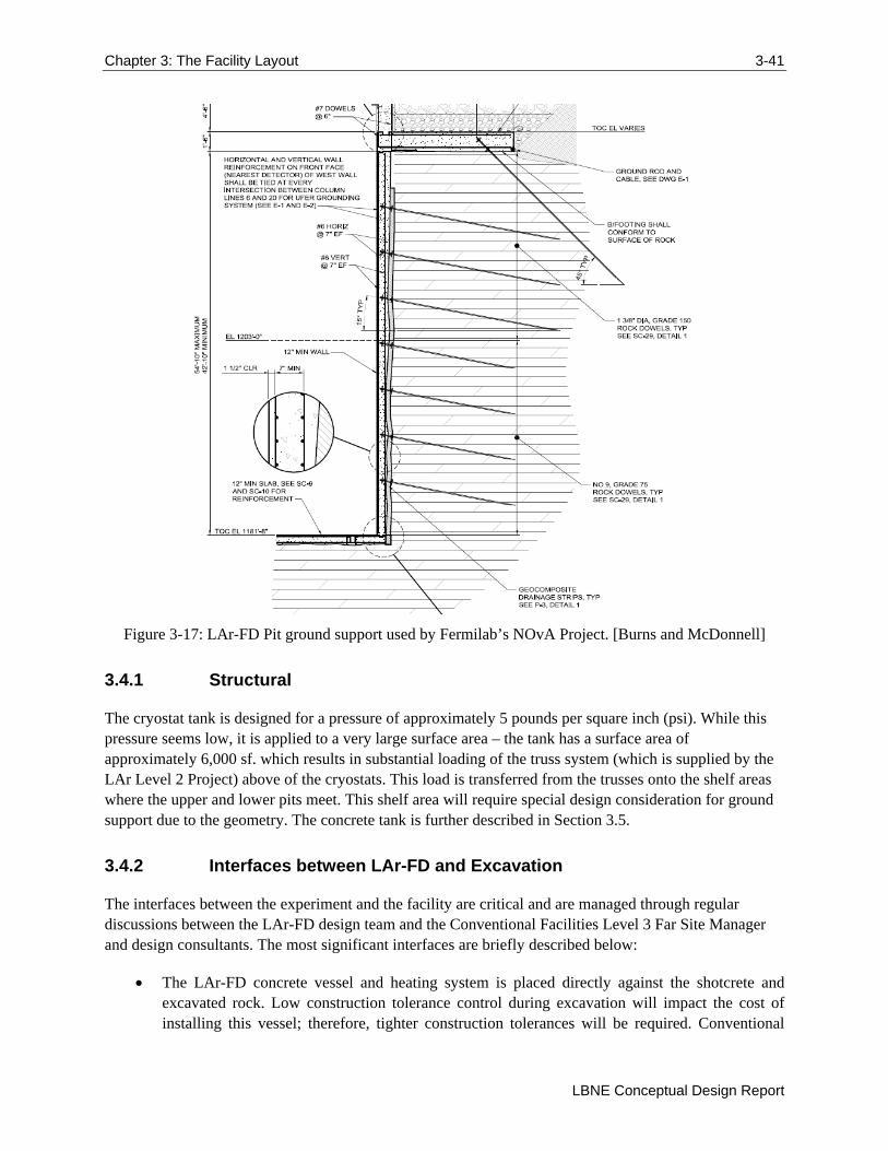
Chapter 3: The Facility Layout 3-41
LBNE Conceptual Design Report
Figure 3-17: LAr-FD Pit ground support used by Fermilab’s NOvA Project. [Burns and McDonnell]
3.4.1 Structural
The cryostat tank is designed for a pressure of approximately 5 pounds per square inch (psi). While this pressure seems low, it is applied to a very large surface area – the tank has a surface area of approximately 6,000 sf. which results in substantial loading of the truss system (which is supplied by the LAr Level 2 Project) above of the cryostats. This load is transferred from the trusses onto the shelf areas where the upper and lower pits meet. This shelf area will require special design consideration for ground support due to the geometry. The concrete tank is further described in Section 3.5.
3.4.2 Interfaces between LAr-FD and Excavation
The interfaces between the experiment and the facility are critical and are managed through regular discussions between the LAr-FD design team and the Conventional Facilities Level 3 Far Site Manager and design consultants. The most significant interfaces are briefly described below:
The LAr-FD concrete vessel and heating system is placed directly against the shotcrete and excavated rock. Low construction tolerance control during excavation will impact the cost of installing this vessel; therefore, tighter construction tolerances will be required. Conventional

3-42 Chapter 3: The Facility Layout
Volume 6: LBNE Conventional Facilities at the Far Site
Facilities will construct the concrete tank and will place conduits within the tank concrete. Later, the LAr-FD Level 2 Project will install heating elements in these conduits to keep the native ground from freezing.
The LAr-FD roof truss supports connect through the concrete tank wall directly to the rock at the bottom of the pit excavation. This requires good excavation elevation grade control as well as substantial ground support for the resultant loads.
3.5 Detector Hall Construction (WBS 130.06.03.05.03.02)
The Detector Hall is based on the design used for Fermilab’s existing NOvA Project in Ash River, MN. The LBNE Detector Hall has an overall footprint of 21,622 SF (2,009 m2), with a low bay section (11.5 ft (3.5 m) inside height) over the detector making up 59% of this, and the high bay (34.4 ft (10.5 m) inside height) the remaining 41%. Concrete walls on all sides and dividing the two detector vessels support the 4 ft (1.2 m) thick concrete roof and a minimum of 9 ft-6-in (2.9 m) of crushed rock for shielding. At the west end of the building is a high bay truck drive-through section that allows detector components to be driven into the building, unloaded, stored, and finally installed within the cryostats. The layout and design for this building is shown in plan view in Figure 3-18. A bridge crane is required to allow the cryostat and detector components to be off loaded from trucks and lowered down into the Detector Pit for assembly. Note that the Detector Hall layout includes a secondary egress stairway at the rear of the Detector Hall exiting up through the roof of the structure.

Chapter 3: The Facility Layout 3-43
LBNE Conceptual Design Report
Figure 3-18: Plan view of Detector Hall. Note the over-the-road truck access and staging areas between this access and the detector. [Fermilab]
The roof for the Detector Building is designed to be capable of supporting a minimum of 3m of shielding material having a density of 2.7 g/cm3 that will be a combination of concrete and crushed rock. Since the rock is taken directly from the excavation, it is permeable and will allow moisture to travel through it. This requires the roof to have an impermeable membrane that can also support the rock fill above. A similar design was required for the NOvA Project in Ash River, MN and has been adopted for the LAr-FD. Shielding from cosmic radiation is required on all sides of this building. One side is naturally shielded by being set against the side of the existing hill. The remaining three sides are designed with a combination of thick concrete walls and/or gabion type rock walls. Figure 3-19 shows all walls at the site and their approximate dimensions.

3-44 Chapter 3: The Facility Layout
Volume 6: LBNE Conventional Facilities at the Far Site
Figure 3-19: Wall descriptions and sizes. [HDR]

References 45
LBNE Conceptual Design Report
References
[1] "US Particle Physics: Scientific Opportunities, A Strategic Plan for the Next Ten Years, Report of
the Particle Physics Project Prioritization Panel," 29 May 2008.
[2] LBNE Collaboration, "The 2010 Interim Report of the Long-Baseline Neutrino Experiment Collaboration Physics Working Groups," FERMILAB-FN-0941-PPD,LBNE-PWG-004; arXiv:1110.6249 [hep-ex], 2011.
[3] Long-Baseline Neutrino Experiment Project, "Project Management Plan (LBNE-doc-2453)".
[4] Long-Baseline Neutrino Experiment Project, "Alternatives Analysis (LBNE-doc-4382)".
[5] Sanford Laboratory, "EHS-1000-L6-01, document 73205, Version 3, dated September 2, 2010," [Online]. Available: https://docs.sanfordlab.org/docushare/dsweb/View/Collection-7391.
[6] Deep Underground Science and Engineering Laboratory, "Preliminary Design Report (LBNE-doc-2417-v2)," May 2011.
[7] T. J. Campbell, "Synopsis of Homestake Mine Geology," [Online]. Available: http://homestake.sdsmt.edu/Geology/geology.htm.
[8] Lachel Felice & Associates, "Geotechnical Engineering Services Final Report for 4850L Mapping (LBNE-doc-2417-v2)," September 2009.
[9] Golder Associates, "LBNE Far Site Detector Excavation Conceptual Design: 4850L Liquid Argon (LAr) Reference Design Final Report (LBNE-doc-4945)," November 4, 2011.
[10] Golder Associates, "In Situ Stress Measurement Deep Underground Science and Engineering Laboratory (LBNE-doc-2417-v2)," January 2010.
[11] A. Davis, C. J. Webb and F. Beaver, "Hydrology of the Proposed National Underground Science Laboratory at the Homestake Mine in Lead, South Dakota," Cincinnati, OH, 2003.
[12] Department of Energy, "Guiding Principles for Sustainable Design and Construction".
[13] LBNE, "LBNE LAr-FD Requirements Document (LBNE-document-4958)".
[14] HDR, "LAr 800L Final Conceptual Design Report for LBNE Surface Facilities at Sanford LaboratoryAppendix 4. (LBNE-doc-6241)," September 30, 2011.
[15] G.L.Tiley, "Finite Element Analysis".
[16] Aon Risk Solutions, Fire Protection Engineering, "Fire Protection/Life Safety Assessment for the Conceptual Design of the Far Site of the Long Baseline Neutrino Experiement (LBNE-doc-4395)," October 11, 2011.
[17] HDR, "LAr 4850L Final Conceptual Design Report for LBNE Surface Facilities at Sanford Lab (LBNE-doc-4945)," November 4, 2011.
[18] Arup, USA, "LBNE at Sanford Lab: 100% Concept Design Report, Task 3a: LAr at 4850L (LBNE-doc-4945)," November 4, 2011.
[19] Golder Associates, "Conceptual Design Excavation Drawings (LBNE-doc-4945)," November 4, 2011.
[20] "Report on the Depth Requirements for a Massive Detector at Homestake (LBNE-doc-34)," 2008.

46 Chapter 3: The Facility Layout
Volume 6: LBNE Conventional Facilities at the Far Site
[21] LBNE Science Collaboration, "LBNE Case Study Report: Liquid Argon TPC Far Detector v1.4," November 1, 2011.
[22] Arup, USA, "Conceptual Design Drawings (consolidated set) for LBNE LAr 4850L (LBNE-doc-4945)," November 11, 2011.
[23] Long-Baseline Neutrino Experiment Project, "Project Management Plan (LBNE-doc-2453)".