long distance communication multiplexing allow multiple signals to travel through one medium types...
Post on 20-Dec-2015
226 views
TRANSCRIPT

Long distance communication

Multiplexing
MultiplexingAllow multiple signals to travel through one
mediumTypes
Frequency division multiplexing Synchronous time division multiplexing Statistical Multiplexing
Frequency Division Multiplexing
Many channels of communication can be transmitted through one medium
Each Channel will transmit on their own frequency.
Television and radio transmit much the same way
Each channel is then de-multiplexed according to the frequency of each communication channel
Used for Analog Signals
Synchronous Time Division Multiplexing (STDM) Used for Digital signals Allows multiple channels of communication over one
communication line. Each channel or computer will take a turn to send a
piece of a message over the line within a frame. In a round robin technique each channel effectively
transmits and places a byte into a frame to be transmitted.
Three types of STDM’s that are used today are T-1 multiplexing ISDN multiplexing SONET/SDH multiplexing
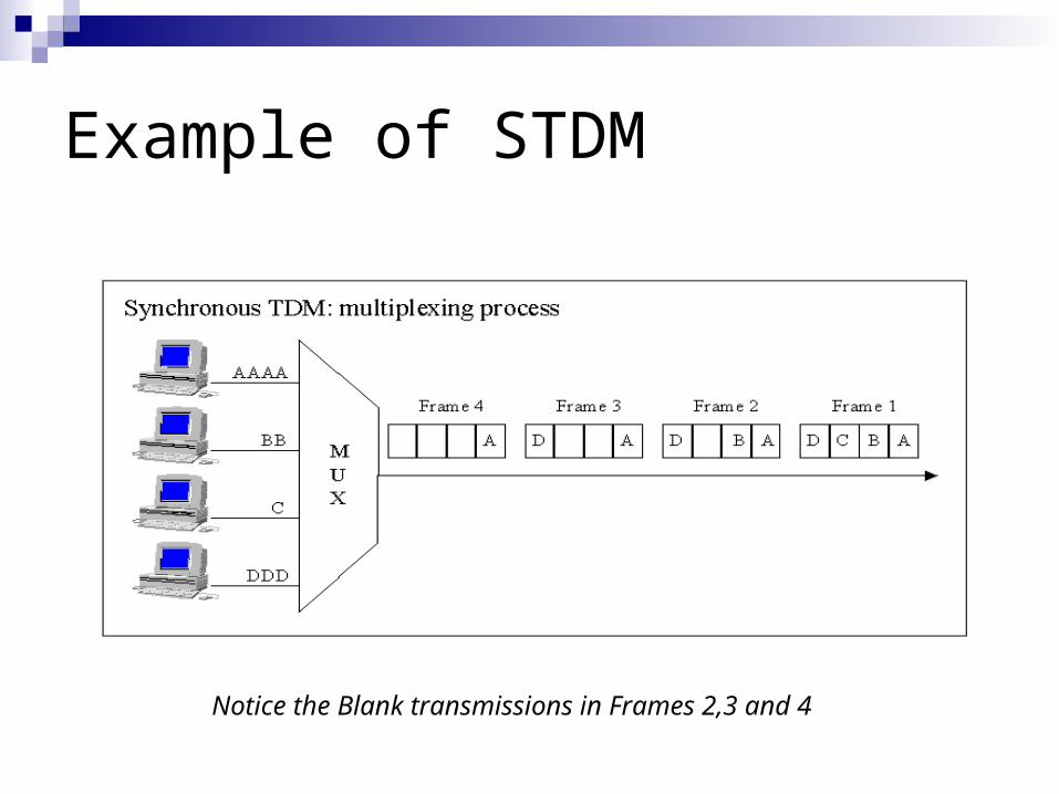
Example of STDM
Notice the Blank transmissions in Frames 2,3 and 4
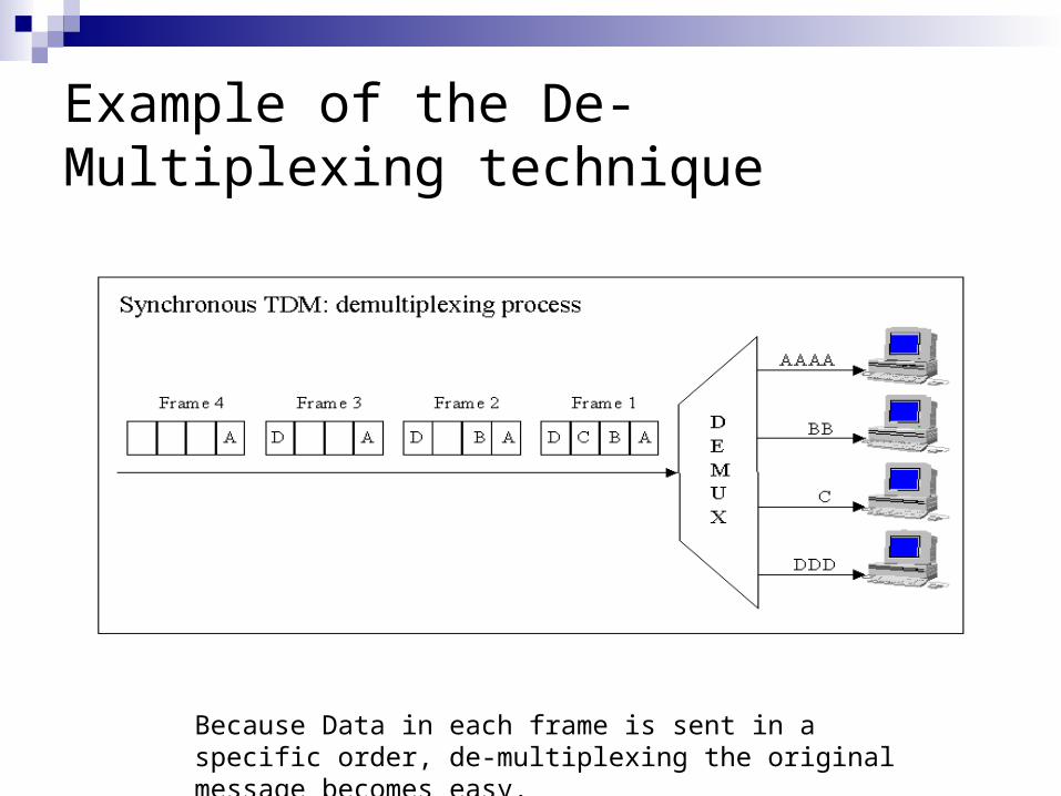
Example of the De-Multiplexing technique
Because Data in each frame is sent in a specific order, de-multiplexing the original message becomes easy.
Synchronous Time Division Multiplexing On the receiving end, each byte within the frame is re-
assembled according to the order that they were sent (Each byte from each channel is Always Sent in the same order with in a frame).
Disadvantage – even when a channel (or computer) does not transmit data, zeros are transmitted in its place (creates overhead).
The communication line is then under utilized and active channels have to wait for the transmission of blank spaces before transmitting more data.
Statistical Multiplexing
Solves the problems addressed by the Synchronous time division multiplexing
Each computer will now send data in data blocks. Each Data Block will contain an address corresponding to the
channel it belongs to Each Data Block will contain the data following the address of each
channel Each block is than placed into a frame to be sent on the
communication line as before Data is from the data blocks within the frame are then re-
assembled according to the addresses Blank transmissions for idle channels are no longer
needed since addressing is used for each channel.
Packets Frames and Error Detection
What is a packet
Provides a means for a sender and a receiver to coordinate the transmission of data
Gives a way to break the data in pieces or small blocks called packets and transmit them over a network
Gives a way to check for errors and only require the “pieces” that caused the error to be re-transmitted.
Dividing messages in packets enables computer equipment and network devices to share expensive networking equipment.
A network device can only hold a network resource long enough to transmit the packet

Packets (Frames) in Time division Multiplexing Bytes from each channel are placed into a frame to be
transmitted over one communication line. Each channel will take a “turn” in transmitting over a
communication line Each Frame will have information that marks the
beginning and the end of the Frame called the SOH and EOT characters
For Statistical Multiplication the channel number are added to the Data blocks within the frame to eliminate the need to transmit 0’s for idle channels.
Hardware Frames
Each frame will have a SOH and an EOT character marking the beginning and the end of the frame.
Disadvantages This adds extra characters and data that is
transmitted over the communication line. These special characters may appear in the data of
the frame and may cause an error in transmission
Structure of a frame
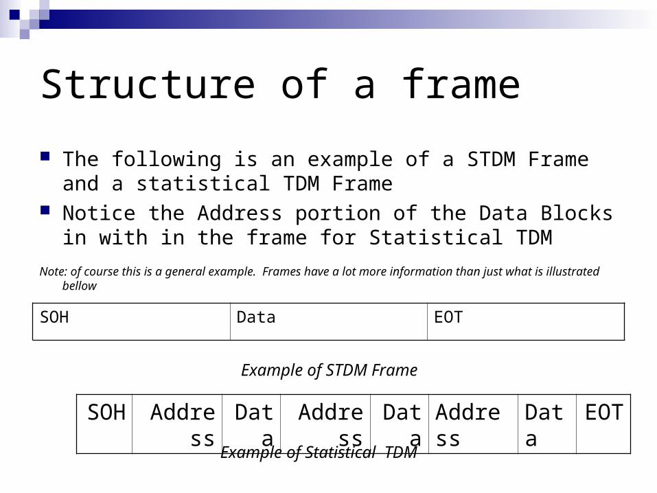
The following is an example of a STDM Frame and a statistical TDM Frame
Notice the Address portion of the Data Blocks in with in the frame for Statistical TDM
Note: of course this is a general example. Frames have a lot more information than just what is illustrated bellow
SOH Data EOT
SOH
Address
Data
Address
Data
Address
Data
EOT
Example of STDM Frame
Example of Statistical TDM
Byte Stuffing
Helps prevent EOT and SOH being detected in the data portion of the frame or packet
Change the data as it is sent to prevent the appearance of the network control character in the data section of the frame.
Using substitute characters in the data stream to represent the special EOT and SOH characters.
Receiver will then replace the special characters with the corresponding SOH and EOT characters within the data stream
Transmission Errors
Errors may occur in the packets or frames during data transmissions
These errors are often caused by noise on the transmission medium.
A form of error checking is needed to provide reliable communications
Two basic types include Simple parity Checksum
Simple Parity

Even Parity
Even Parity will check the number of 1’s in a character.
If there are an odd number of ones the parity bit will be turned on to make it even
If there are an even number of ones, the parity bit will remain off to keep the number of ones in the byte even.
Odd Parity
Works in the same manner as even parity If the character or byte contains an odd
number of ones, the parity bit is set to 0. If the character or byte contains an even
number of ones, the parity bit is turned on to maintain odd parity.
Simple parity in general
The number of ones in a byte are maintained according to the parity standard chosen.
Both the sender and receiver must use the same standard for this to work.
Often can detect a spike that may occur in a transmission line that will change one of the bits in the byte.
Will not be able to detect two spikes or when two bits change within a byte.

Longitudal Or Vertical Parity Check A byte is added that
checks the parity of a group of bytes.
Parity bits at the end of the byte are also checked
Solves the problem when two spikes occur.
Does not solve all transmission errors that may occur.
1 0 1 0 1 0 1 1
1 1 1 1 0 1 0 0
1 0 1 0 0 0 0 1
1 0 1 1 1 0 0 1
1 0 0 0 1 0 1 0
1 1 0 1 0 0 1 1
1 1 1 1 1 0 0 0
Parity Byte
0 0 0 1 1 0 0 1

Checksum Error Checking
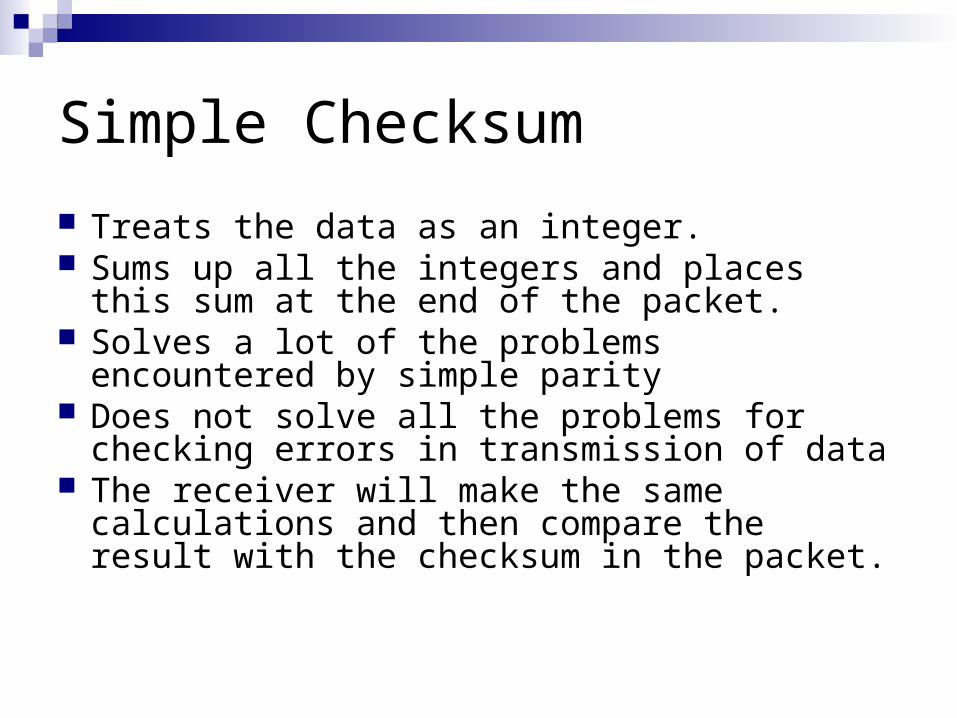
Simple Checksum
Treats the data as an integer. Sums up all the integers and places this sum at
the end of the packet. Solves a lot of the problems encountered by
simple parity Does not solve all the problems for checking
errors in transmission of data The receiver will make the same calculations
and then compare the result with the checksum in the packet.
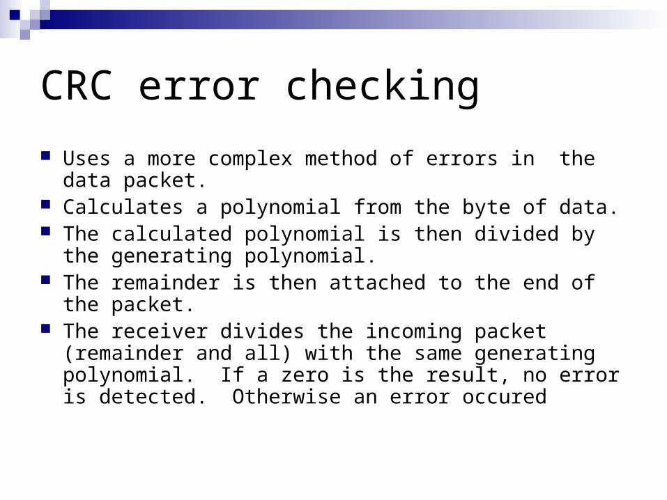
CRC error checking
Uses a more complex method of errors in the data packet.
Calculates a polynomial from the byte of data. The calculated polynomial is then divided by the
generating polynomial. The remainder is then attached to the end of the packet. The receiver divides the incoming packet (remainder and
all) with the same generating polynomial. If a zero is the result, no error is detected. Otherwise an error occured

CRC Generating Polynomials
Generating Polynomial An industry approved bit string used to create
CRC remainders. Types include
CRC-12 CRC-16 CRC-CCITT CRC-32
1231112 xxxxx
121516 xxx
151516 xxx
1245781011121622232632 xxxxxxxxxxxxxx
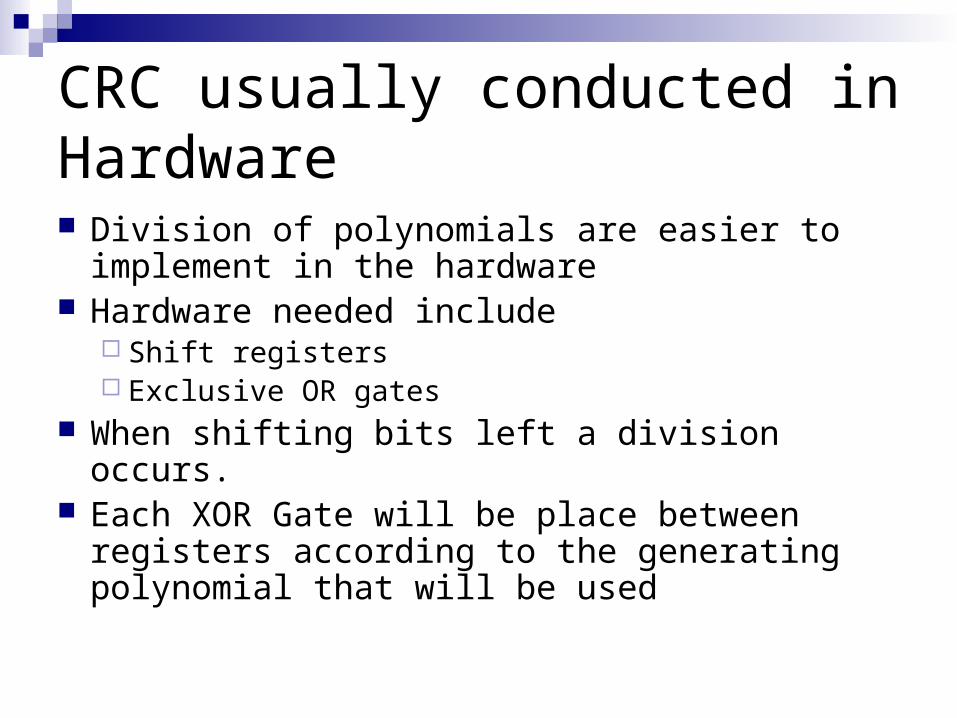
CRC usually conducted in Hardware Division of polynomials are easier to implement
in the hardware Hardware needed include
Shift registers Exclusive OR gates
When shifting bits left a division occurs. Each XOR Gate will be place between registers
according to the generating polynomial that will be used
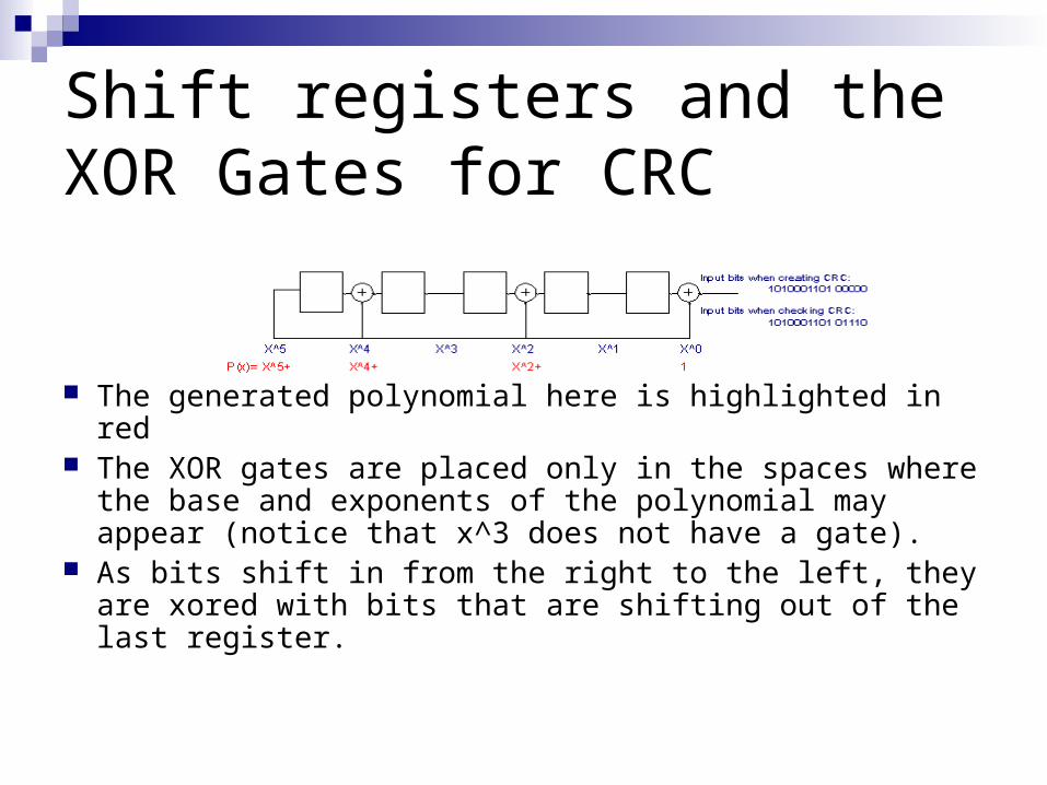
Shift registers and the XOR Gates for CRC
The generated polynomial here is highlighted in red The XOR gates are placed only in the spaces where the
base and exponents of the polynomial may appear (notice that x^3 does not have a gate).
As bits shift in from the right to the left, they are xored with bits that are shifting out of the last register.
Shifting continued
The shift registers are usually the size of the checksum
The same hardware can be used for calculating the checksum and checking it.
When calculating the checksum the incoming data is padded with 0’s the size of the checksum
The resulting number in the registers become the checksum remainder.
Shifting Continued
When checking the checksum, the same process is run on the incoming data including the checksum
The result in the registers when the process should be zero when there are no errors
If the result is greater than zero, an error occurred
CRC Conclusion
It is implemented quickly through the use of hardware
It is the closest to 100 percent reliability in finding errors in data transmissions
Is used widely in the Internet, LAN, and WAN networks Ethernet uses CRC-32 Internet uses CRC-16
Types of Errors
Vertical errors Errors that occur in multiple bytes of information Vertical parity check helps solve most of these errors
but not all. Burst errors
Occur in or around the same location in a data stream.
These errors occur sporadically and are hard to detect.
CRC error checking can detect both these types of errors the best.
Checking for errors in the frame format Errors can also be checked by examining
the format of the frame as it arrives to the receiver
If the frame is not in the correct format, reject the frame
Frames that have errors are discarded and new frames are requested and then sent