long distance subsea control - norwep · pdf filelong distance subsea control | 4 field- and...
TRANSCRIPT

Long Distance Subsea Control
Sigurd Moe
Cairo, 12. February .2017

Long Distance Subsea Control | 2
� Introduction
� Subsea control system architecture
� Power and communication
� Technology opportunities
Agenda

Long Distance Subsea Control | 3
• Gas
• 50 - 300 km subsea to beach• 600 km studied and deemed feasible
• Flow assurance crucial
• Hydrate control • Multiphase (Wet gas) metering
• Continous hydrate inhibitor injection (MEG)
• System for remote control of injection per well
• Slug handling
• Large bore, lots of energy, enhanced monitoring being requested
• Sand detection
• Vibration monitoring
• Leakage detection
• Need for accurate positioning of chokes to balance wells• Electric choke valve resolution advantageous
• Gas Compression often considered in late life
Long distance field charcteristics
Shell Ormen Lange – 120 km Subsea to beach Norway
Subsea System by TechnipFMC, production start 2007
Laggan Tormore
Total Laggan Tormore – 187 km Subsea to beach UK. Subsea System
by TechnipFMC, production start 2016
Long Distance Subsea Control | 4
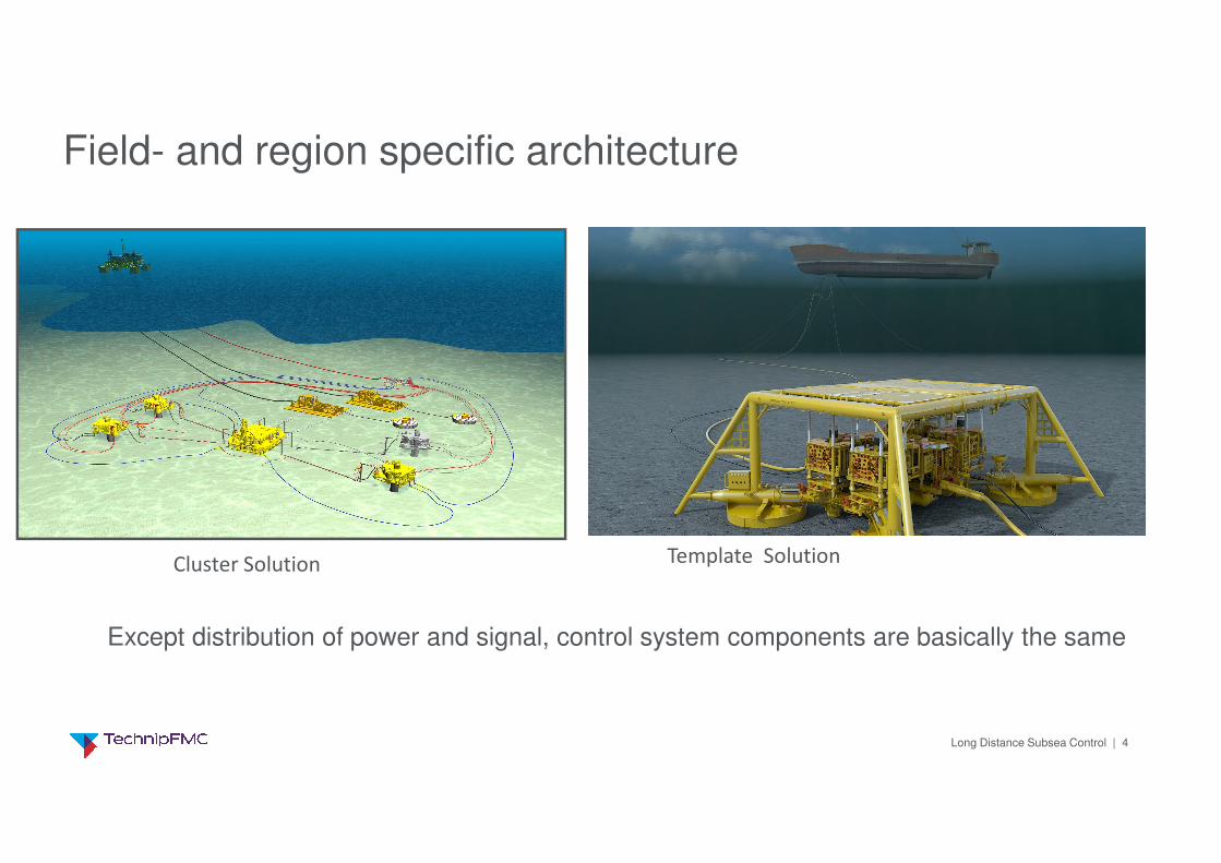
Field- and region specific architecture
Cluster Solution Template Solution
Except distribution of power and signal, control system components are basically the same

Long Distance Subsea Control | 5
Functionality - Subsea Control System
1. Safety - Automatically or manually shuts in the subsea system
in abnormal situations
2. Operator Interface during Daily Operation- Operation of subsea valves and chokes
- Monitoring of production parameters and system integrity
3. Provides Data for Reservoir Management- Monitors, stores and trends pressure and temperature
and other reservoir related parameters
Long Distance Subsea Control | 6
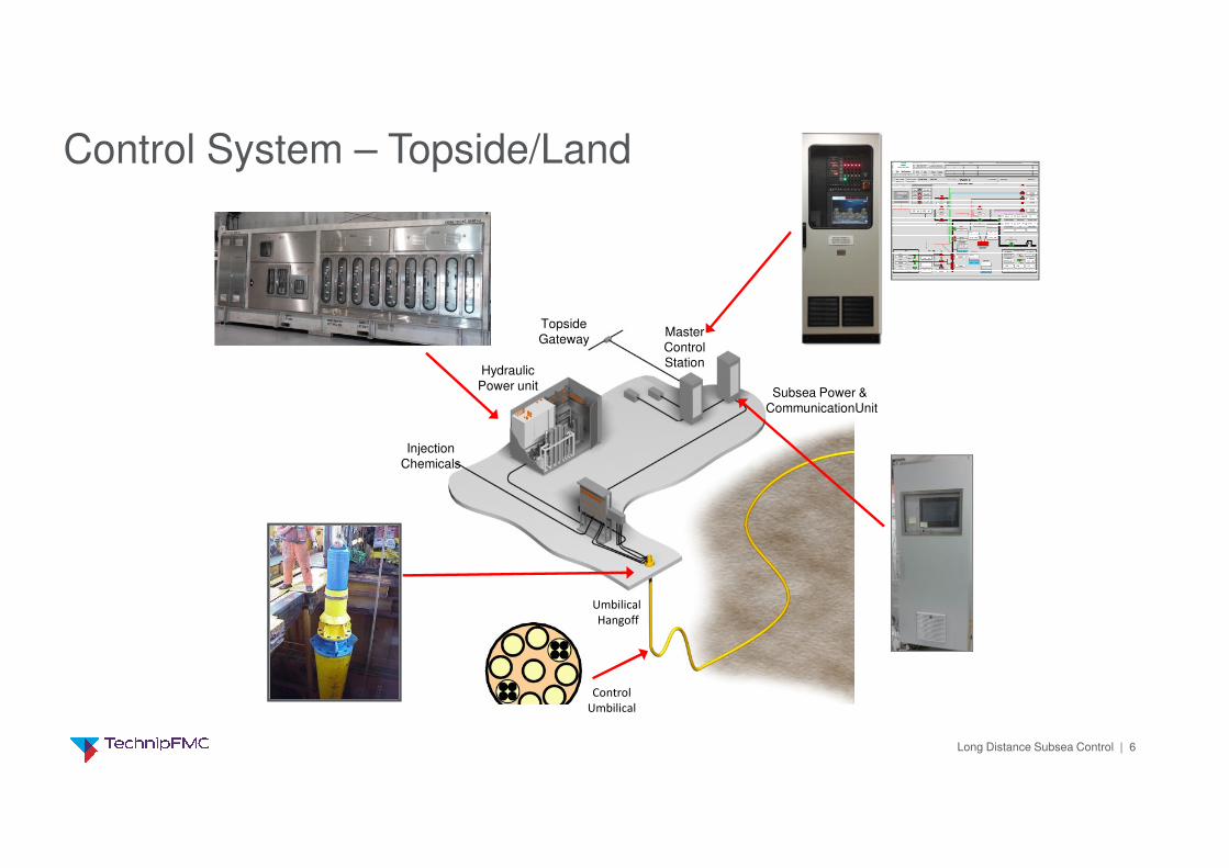
Control System – Topside/Land
Injection
Chemicals
Hydraulic
Power unit
Master
ControlStation
Subsea Power &
CommunicationUnit
Topside
Gateway
Control
Umbilical
Umbilical
Hangoff

Long Distance Subsea Control | 7
Subsea Equipment
Tree Mounted Controls - Instrumentation and Subsea Control Module
Power consumption:• 200 – 300 W per well
Communication, typical:• 1- 5 kbps per well for normal
operation• 1 Mbps + if seismic data or video
streaming

Long Distance Subsea Control | 8
Umbilical and Distribution
Template distribution
Umbilical
Cluster distribution

Long Distance Subsea Control | 9
Power and Communication Architecture
Communication
on power cable
Point to point
fiber optical
communication
Distribution using
Subsea Router Module
(SRM)
Subsea Router Module
(SRM) with topside
functionality “Topside
repeated subsea”

Long Distance Subsea Control | 10
Communication on power cable
Multidrop
communication
on power cable
• Normally lowest cost solution• Uses power lines for communication• No subsea router needed• No fiberoptics
• Shorter distances, up to 80 km typically• But 120 km field proven @ 1200 bps
• Typically two (redundant) cable pairs per 4
wells• 8 - 12 wells possible
• Up to 900 V in operation
• Communication speed• 1.5 Mbps up to 40 km• 100 kbps up to 80 km
Long Distance Subsea Control | 11
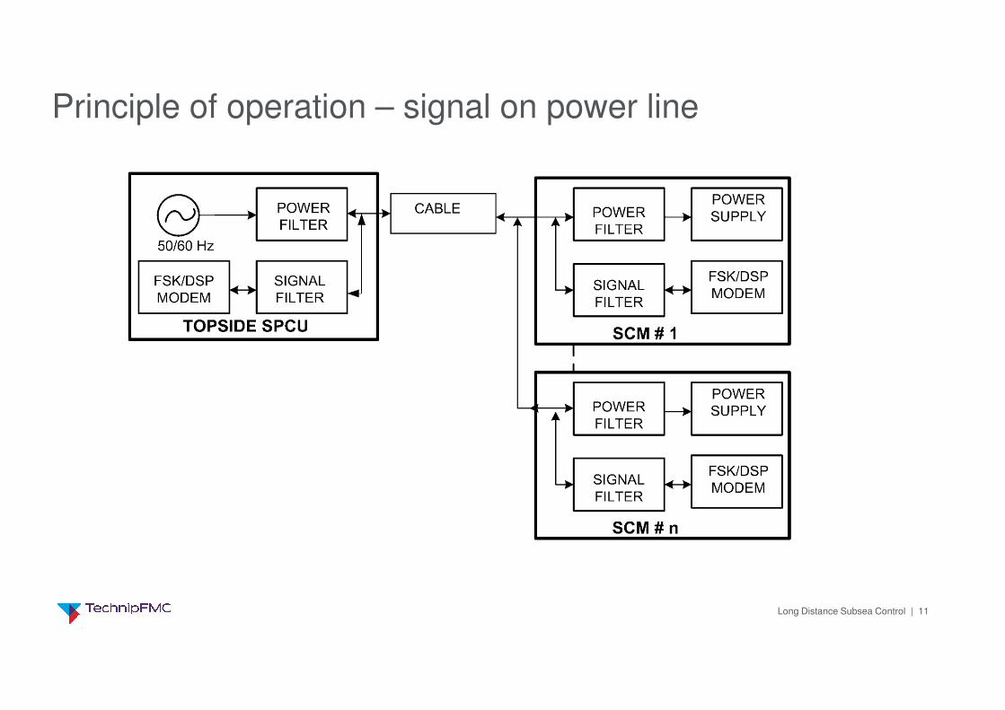
Principle of operation – signal on power line

Long Distance Subsea Control | 12
Signal transmission over the power lines will eliminate the need for dedicated signal cables;
• Increases reliability as component count (cable elements and connector pins) is divided by 2
• Reduces control umbilical cost with typically more than 5%
• Increases distance as power cables normally have larger cross section than signal cables
Why Signal on Power Line?
Umbilical with separate signal cable Umbilical for communication on power line

Long Distance Subsea Control | 13
Point to point fiber optical communication
Point to point
fiber optical
communication
• Up to 200 - 250 km typically
• No subsea routers required
• Fiberoptic communication • High speed (1 Gbps) • Noise immune
• Power distribution 900 V – 3 kV AC

Long Distance Subsea Control | 14
Distribution using Subsea Router Module (SRM)
Distribution using
Subsea Router Module
(SRM)
• Typically 250 km with 3 kV AC
• One redundant pair of cables for many (20+) wells
• Fiberoptic communication for high speed (1 Gbps)
• Ethernet distribution locally (100 Mbps - 100 m)• Optionally modem to “repeat topside subsea”
Subsea Router Module
(SRM) with topside
functionality “Topside
repeated subsea”
Subsea Router Module

Long Distance Subsea Control | 15
Fiber optic experience
Shallow waterShort distanceFibers to XT SCMCoP as backup
Deeper waterLong distanceFibers to XT SCMCoP as backup
Fibers to subsea routerCoP as backupEthernet to XT SCM
Fibers to subsea routerFiber only Ethernet to SCM
Fibers to central subsea routerCoP infield
Fiber repeaterOne-to-oneOne-to-many
2001, Fram Vest (Statoil)
2005, Ormen Lange (Shell)
2007, Tyrihans (Statoil)
2011, Pazflor (Total)
2013, Laggan Tormore (Total)

Long Distance Subsea Control | 16
Bandwith / offset:
• 1GE (Gigabit Ethernet) � 40dB without in-line attenuation ~125 km
• 100M� 51dB without in-line attenuation ~ 190 km
• 10M���� 60dB without in-line attenuation . ~225 km
Capabilities are based on 0.2dB/km loss and 15dB margin
Assumptions:
• 0.2dB/km loss in fiber. Low loss fiber with 0.175dB/km loss is available.
• Conservative margins included:
• 5dB loss for ageing and variation in cable vs. umbilical length
• 10dB margin included.
Fiber optic communication system capabilities

Long Distance Subsea Control | 17
AC parameters:
� Transmission 3.0 kVAC, 167km
� Distribution 600Vac, up to 6.6km
DC parameters:
� Transmission 1.2 kVDC, 167km
� Distribution 400Vdc up to 6.6km
Power - 3 kV AC vs 1.2 kV DC - 167 km example
AC DC
Transmission to single SDU, exp.
25% voltage drop for 1610W
Pair 16 mm2
redundancy A+B: 2 pair
1 pair 35 mm2
redundancy A+B: 2 pair
Distribution from SDU to single
load, exp. ΔU=5%, 300W
Pair 6 mm2
Red. A+B: 2 pair
Pair 10 mm2
Red. A+B: 2 pair
Efficiency Pout / Sin [%] With L-compensation: ≈19%
Without: ≈8%
No compensation necessary:
≈70%
• AC voltage is easily transformed, simple transformer instead of a complex DC/DC converter• AC has no issue with earth fault (would damage cathodic protection in a DC system)• AC has lower efficiency – but of marginal importance for a control system (low power)
Long Distance Subsea Control | 18
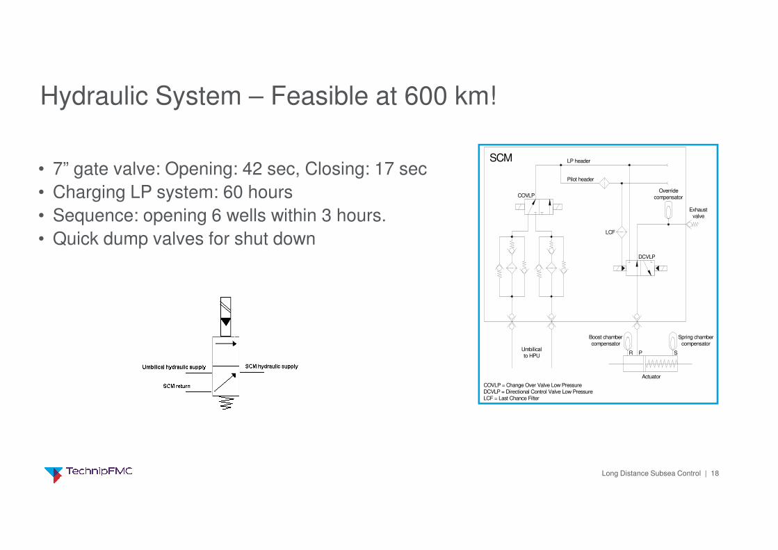
Hydraulic System – Feasible at 600 km!
SCM LP header
Pilot header
Override
compensator
Exhaustvalve
DCVLP
LCF
COVLP
Umbilicalto HPU
Boost chamber
compensator
Spring chamber
compensator
R P S
Actuator
COVLP = Change Over Valve Low Pressure
DCVLP = Directional Control Valve Low Pressure
LCF = Last Chance Filter
• 7” gate valve: Opening: 42 sec, Closing: 17 sec
• Charging LP system: 60 hours
• Sequence: opening 6 wells within 3 hours.
• Quick dump valves for shut down

Long Distance Subsea Control | 19
• Control Umbilical Cost Reduction is the key!• The rest of the control system is basically unchanged!
Long Distance Cost Reduction Technology Options
Long Distance Subsea Control | 20
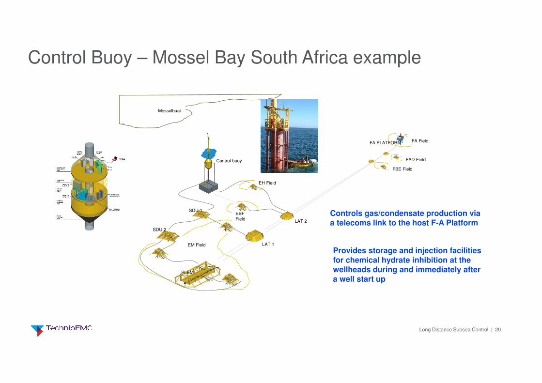
Control Buoy – Mossel Bay South Africa example
EM Field
EBF
Field
EH Field
Mosselbaai
FA Field
FAD Field
FBE Field
SDU 1
SDU 2
Control buoy
PLEM
LAT 1
LAT 2
FA PLATFORM
Controls gas/condensate production via a telecoms link to the host F-A Platform
Provides storage and injection facilities for chemical hydrate inhibition at the wellheads during and immediately after a well start up

Long Distance Subsea Control | 21
• Communication on power cable, eliminates separate signal cables
• For very long distances: • Routers to reduce number of cables
• 3 kV AC to reduce cable cross section
Minimize Cable Count

Long Distance Subsea Control | 22
• Hydraulic Pressure Intensifier (HPI)• Can be integrated part of SCM
• No high pressure at surface
• Proven in use • Topside
• Workover
• Subsea
Eliminate High Pressure (HP) Lines
MQC plate mounted HPI

Long Distance Subsea Control | 23
Electric actuator technology:
• In general less sensitive to long offsets and water depth
Choke• Improved response time and resolution
• Simultaneous operations
• No choke hydraulic fluid consupltion
Large valves:• Less accumulation and fluid consumption (e.g. Manifold)
• Save space and weight by removing hydraulic actuators
All-electric Tree a future• Higher potential on long offsets
• Still maturing technology
Replace hydraulics with electric actuators
G2i Actuator G3 Actuator for subsea gas compression

Long Distance Subsea Control | 24
Electric choke valve control:
• Quick and accurate
• Choke vibration information and exact position available
• Actuator retrievable independent of choke
• Eliminates largest hydraulic fluid consumer
Electric Choke Actuation
Hydraulic Stepping actuator G2i Electric Actuator
Long Distance Subsea Control | 25
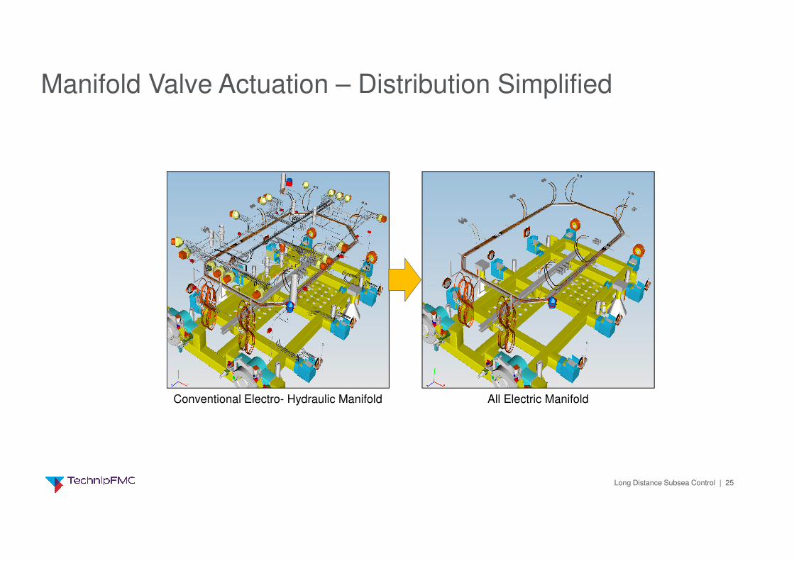
Manifold Valve Actuation – Distribution Simplified
Conventional Electro- Hydraulic Manifold All Electric Manifold
Long Distance Subsea Control | 26
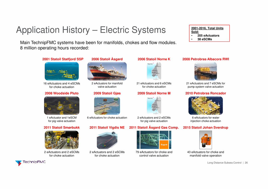
Application History – Electric Systems
2001 Statoil Statfjord SSP
16 eActuators and 4 eSCMsfor choke actuation
2006 Statoil Åsgard
2 eActuators for manifold
valve actuation
2006 Statoil Norne K
21 eActuators and 6 eSCMs
for choke actuation
2008 Petrobras Albacora RWI
21 eActuators and 7 eSCMs for
pump system valve actuation
2008 Woodside Pluto
1 eActuator and 1eSCM
for pig valve actuation
2009 Statoil Gjøa
6 eActuators for choke actuation
2009 Statoil Norne M
2 eActuators and 2 eSCMs
for pig valve actuation
2010 Petrobras Roncador
6 eActuators for water
injection choke actuation
2011 Statoil Smørbukk
2 eActuators and 2 eSCMsfor choke actuation
2011 Statoil Vigdis NE
2 eActuators and 2 eSCMsfor choke actuation
2011 Statoil Åsgard Gas Comp.
79 eActuators for choke and control valve actuation
Main TechnipFMC systems have been for manifolds, chokes and flow modules. 8 million operating hours recorded:
2001-2016, Total Units Sold:• 205 eActuators• 38 eSCMs
43 eActuators for choke and manifold valve operation
2015 Statoil Johan Sverdrup

Long Distance Subsea Control | 27
Thank You!