long term data retention of weapon system information ... · mining the shipconstructor product...
TRANSCRIPT

Naval Surface Warfare Center Carderock Division West Bethesda, MD 20817-5700
DISTRIBUTION STATEMENT A: Approved For Public Release : Distribution Unlimited
NSWCCD-20-TR–2010/06 October 2010
Ship Systems Integration and Design Department Technical Report
Long Term Data Retention of
Weapon System Information FY2010 Final Report
by Ben Kassel and Paul Rakow
NSW
CC
D-2
0-TR
–201
0/06
Lo
ng T
erm
Dat
a R
eten
tion
of W
eapo
ns S
yste
m In
form
atio
n FY
2010
Fin
al R
epor
t

REPORT DOCUMENTATION PAGE Form Approved
OMB No. 0704-0188 Public reporting burden for this collection of information is estimated to average 1 hour per response, including the time for reviewing instructions, searching existing data sources, gathering and maintaining the data needed, and completing and reviewing this collection of information. Send comments regarding this burden estimate or any other aspect of this collection of information, including suggestions for reducing this burden to Department of Defense, Washington Headquarters Services, Directorate for Information Operations and Reports (0704-0188), 1215 Jefferson Davis Highway, Suite 1204, Arlington, VA 22202-4302. Respondents should be aware that notwithstanding any other provision of law, no person shall be subject to any penalty for failing to comply with a collection of information if it does not display a currently valid OMB control number. PLEASE DO NOT RETURN YOUR FORM TO THE ABOVE ADDRESS. 1. REPORT DATE (DD-MM-YYYY) 20-Oct-2010
2. REPORT TYPEFinal
3. DATES COVERED (From - To)1-Oct-2005 - 30-Sep-2010
4. TITLE AND SUBTITLE
Long Term Data Retention of Weapons System Information FY2010 Final Report
5a. CONTRACT NUMBER NAMA-06-I-0016 5b. GRANT NUMBER
5c. PROGRAM ELEMENT NUMBER
6. AUTHOR(S)
Ben Kassel and Paul Rakow
5d. PROJECT NUMBER
5e. TASK NUMBER
5f. WORK UNIT NUMBER
7. PERFORMING ORGANIZATION NAME(S) AND ADDRESS(ES) AND ADDRESS(ES) 8. PERFORMING ORGANIZATION REPORT NUMBER NSWCCD-20-TR-2010/06
NAVAL SURFACE WARFARE CENTER CARDEROCK DIVISION (CODE 2230) 9500 MACARTHUR BOULEVARD WEST BETHESDA, MD 2817-5700
9. SPONSORING / MONITORING AGENCY NAME(S) AND ADDRESS(ES) 10. SPONSOR/MONITOR’S ACRONYM(S)NARA Center for Advanced Systems and Technologies Office of Information
Services (NH) National Archives and Records Administration 860 I Adelphi Road, Suite 3310 College Park, MD 20740-6001
11. SPONSOR/MONITOR’S REPORT NUMBER(S)
12. DISTRIBUTION / AVAILABILITY STATEMENT DISTRIBUTION STATEMENT A: Approved For Public Release : Distribution Unlimited
13. SUPPLEMENTARY NOTES
14. ABSTRACT The Long Term Data Retention of Weapons Systems project is a multi-year, long term research program to ensure that future users have access to the required data to support the lifecycle of their weapon system. This includes the effort to look at the requirements and issues involved with the: Transition to 3-D product model data in numerous forms and quantities; Aggregation of product models and related data from individual components to complete weapons systems; and Long-term accessibility and interpretability of the archived digital data by future generations. To support the future users of the weapon systems data, the “new” logistics repositories must accommodate existing uses of the data while anticipating implementation of advanced technologies throughout the lifecycle of the weapon system. It will require highly scalable processing mechanisms, international standards, digital engineering data, and other technologies to address NARA’s, DoD’s and the individual service’s critical requirements for preserving and providing access to weapons systems information required for the nation’s security and defense.
15. SUBJECT TERMS
16. SECURITY CLASSIFICATION OF: 17. LIMITATION OF ABSTRACT
SAR
18. NUMBER OF PAGES
16
19a. NAME OF RESPONSIBLE PERSONBen Kassel
a. REPORT UNCLASSIFIED
b. ABSTRACT UNCLASSIFIED
c. THIS PAGEUNCLASSIFIED
19b. TELEPHONE NUMBER (include area code) 301 227 1355
i/ii
Standard Form 298 (Rev. 8-98)Prescribed by ANSI Std. Z39.18

NSWCCD-20-TR–2010/06
iii
Contents Figures............................................................................................................................................ iii
Administrative Information ........................................................................................................... iv
Executive Summary .........................................................................................................................1
Scope ................................................................................................................................................1
FY2006 – FY2009 ...........................................................................................................................2 Steering Committee Priorities .................................................................................................2 Technologies ...........................................................................................................................2
Shipbuilding STEP Application Protocols .....................................................................2 Native Data ....................................................................................................................3 General Purpose STEP Application Protocols ...............................................................4
Test Data Set ...........................................................................................................................5 Ship Product Model Data ...............................................................................................6 Other Technical Data .....................................................................................................8
FY2010 ............................................................................................................................................8 Mining the ShipConstructor Product Model Data ..................................................................9 AP214 / AP239 Feasibility ...................................................................................................10 Approach ...............................................................................................................................10 Data Exchange Specification ................................................................................................11 Ship Reference Data Library ................................................................................................13
Additional Benefits ........................................................................................................................14 LEAPS IGES Bulk Loader ...................................................................................................14 Torpedo Weapons Retriever CAD Model ............................................................................14 Small Business Innovative Research ....................................................................................15 Interagency Communication .................................................................................................15
Epilogue .........................................................................................................................................15
Figures
Figure 1 – Wide range of data to be captured ..................................................................................5 Figure 2 – Non-graphical Attributes ................................................................................................6 Figure 3 – Compartmentation Model ...............................................................................................7 Figure 4 – Piece part manufacturing level of detail .........................................................................7 Figure 5 – Ship check sketch and topside photograph .....................................................................8 Figure 6 – Information mined from the native data .........................................................................9 Figure 7 – Data Exchange Specification Architecture ...................................................................11 Figure 8 – ShipLTDR DEX templates ...........................................................................................12

NSWCCD-20-TR–2010/06
iv
Administrative Information
The Design Tool Development Branch (Code 2230) of the Future Concepts & Design Integration Process Division (Code 22) of the Ship Systems Integration and Design Department (Code 20) at the Naval Surface Warfare Center, Carderock Division (NSWCCD), performed the work described in this report. The work was funded by the National Archives and Records Administration as part of a five year effort for joint research activities for the long-term data retention of weapon systems information and electronic records supporting weapon systems digital collection under Interagency Agreement NAMA-06-I-001 having a total value of $1,704,443.66.

NSWCCD-20-TR–2010/06
1
Executive Summary
The Long Term Data Retention of Weapons Systems project is a multi-year, long term research program conducted by Naval Surface Warfare Center – Carderock Division under direct funding of the National Achieves and Records Administration.
As DOD acquisition contracts transition from electronic drawing based archive data sets to contract requirements for digital product model data, the respective agencies need to ensure that future users have access to the required data to support the lifecycle of their weapon system.
This includes the effort to look at the requirements and issues involved with the: Transition to 3-D product model data in numerous forms and quantities; Aggregation of product models and related data from individual components to complete weapons systems; and Long-term accessibility and interpretability of the archived digital data by future generations.
To support the future users of the weapon systems data, the “new” logistics repositories must accommodate existing uses of the data while anticipating implementation of advanced technologies throughout the lifecycle of the weapon system.
It will require highly scalable processing mechanisms, international standards, digital engineering data, and other technologies to address NARA’s, DoD’s and the individual service’s critical requirements for preserving and providing access to weapons systems information required for the nation’s security and defense.
The research yielded a conclusion that at this time, the most viable approach for the long term data retention for ships data involves the use of ISO standard 10303, the Standard for the Exchange of Product Model data. And although a great deal of time and effort was invested by the Naval Sea Systems Command to develop application protocols specifically for the marine industry, a better approach involves the use of the more general purpose application protocols, Data Exchange Specifications (DEX), and Reference Data Libraries (RDL) to represent geometry, product structure, and non graphical attributes. An added benefit is this approach can be applied across all of the industrial sectors that have direct involvement in the defense industry.
Scope
Among issues and challenges to be addressed are areas responsive to national security of United States Navy warships and ship born systems. The purpose of this IA is to allow NARA to conduct joint research concerning technologies and technology enabled processes required to manage, preserve and support robust sustainable access to complex weapons system information and electronic records supporting weapon systems digital design processes. This research will specifically leverage and apply the expertise, experience and the Nation's continuing investment in the advanced technologies and logistics repository capabilities of the Defense Logistics Agency, Joint Engineering Data Management Information Control System ("JEDMICS"), U.S. Navy Sea Systems Command, and the U.S. Navy Air Systems Commands. This collaboration will investigate and rigorously evaluate through pilot activities the technologies and processes

NSWCCD-20-TR–2010/06
2
required to archive weapons system information. This research presents a novel effort to look at the requirements and issues involved with the:
• transition of ship and ship borne weapon system design processes to apply complex 3-D product model data
• aggregation of product models and related data from individual components to complete weapons systems
• long-term accessibility and interpretability of the archived digital data by future generations.
Included research will address highly scalable novel processing mechanisms, international standards, digital engineering data, and other technologies to address NARA's, DoD's and service's critical requirements for preserving and providing access to weapons systems information required for the nation's security and defense.
FY2006 – FY2009
During the first four years of the project, work was focused on determining the priorities of the steering committee, exploring technologies, and developing a test data set.
Steering Committee Priorities
The priorities of the steering committee closely mirrored the prevailing paper based attitude of the industry. There was widespread acknowledgement of the use of 3D Product Model data, but the overwhelming concern was access to the electronic analogy to technical publications and drawing sheets. Typically the priority for electronic data rested on the native format. For CAD, this was primarily AutoCAD. Once again the major concern was for the native CAD data used to create 2D drawings. This set the tone for much of the first year of the project which concentrated on the generation of 3D geometry, not much of an emphasis on the non graphical attributes, and not much interest on a neutral file format. Ultimately though during this phase, a limited number of STEP AP 2031 files were generated.
Technologies
Data definition and exchange technologies were limited to three categories during the first two years of the program. These were, native, STEP AP203, and IGES. The majority of the effort was to determine the state of neutral file data exchange and processes for managing the relationship between drawings, other technical data, native data, and neutral file representations. Since the industry sector of primary interest for this project was shipbuilding, the STEP shipbuilding application protocols were evaluated.
Shipbuilding STEP Application Protocols At the 2007 Society of Naval Architects and Marine Engineers Ship Production
Symposium some of the results of the NARA funded research were presented in the paper, “An
1 The geometry definition used by AP203 and AP214 are in many respects, similar. For this report, unless
AP214 is specifically called out, it can be assumed that either AP203 or AP214 were used to define the geometric data.

NSWCCD-20-TR–2010/06
3
Alternate Approach to the Exchange of Ship Product Model Data”. The following overview of the STEP shipbuilding application protocols was extracted from that paper.2
STEP, is a family of international standards defined by the ISO. The STEP standard is organized as a family of Parts, each of which is issued separately. These specifications have been under development since the mid 1980s, with International Standards issued beginning in 1994. The STEP standards define computer-interpretable representations for the sharing of product data and long-term data archiving. The core application protocols required for shipbuilding have now reached International Standard status. After over 16 years of requirements definition and consensus building, three shipbuilding specific application protocols (AP216, AP218, and AP215 have been approved by ISO as International Standards. AP227 has been modified to include shipbuilding requirements for Pipe, HVAC, cableway, mechanical systems, as well as the production of those systems. Edition 2 of this standard has been approved as an International Standard. AP212 for electrical distribution systems has been an International Standard since 2001.
The lack of commercially available STEP shipbuilding translators has resulted in part from the need to implement several interrelated translators for a rather small and specialized market. Each shipbuilding translator is specified by a separate standard, with separate concepts and entities, defined across a thousand or more pages. Hence, each translator requires substantial effort and must be developed independently. Further, there is only a limited market and, at least currently, a weak demand for these specialized translators. Most vendors simply provide a generic exchange capability by implementing translators for AP203 or AP214. The reality is that the outlook for commercially available STEP shipbuilding translators within the next five years remains bleak.
Native Data Native data is the product model stored in the format used by the tool to create the data. It
is typically proprietary and requires a specific tool that will need to be purchased. If the tool is no longer available, it may be difficult to reverse engineer the data file to the level necessary to extract information. However, it typically contains the most robust representation of the product model data. In addition, since the data has already been developed and requires no additional post-processing, the only cost associated with native data is the cost to catalog, and store the data. The use of native data as the primary means for the purposes of long term archival, present more problems than they solve. The utility of the native data increases as a function of how open the system is. Basically, if the system is based on an open architecture and has a freely published schema, there is a potential that it its value may be on par with a neutral representation that complies with an international standard. LEAPS (Leading Edge Architecture for Prototyping Systems) is an example of a native system that has a freely published schema, has product data that can be exported to an XML formatted text file conforming to that schema.
2 Kassel and Briggs, An Alternate Approach to the Exchange of Ship Product Model Data, Journal of Ship
Production volume 24 number 2, pp94, SNAME, May 2008.

NSWCCD-20-TR–2010/06
4
General Purpose STEP Application Protocols At the 2007 Society of Naval Architects and Marine Engineering Ship Production
Symposium some of the results of the NARA funded research were presented in the paper, “An Alternate Approach to the Exchange of Ship Product Model Data”. The following discussion about the use of AP203 and AP214 to define geometry, and AP239 for non geometric data was extracted from that paper.3
Simply stated, the alternate approach to the shipbuilding application protocols is to use AP239 to define product structure and the relationships between objects, use reference data libraries to define properties, and use AP203 or AP214 to define shape. This does not diminish the efforts spent on the development of the shipbuilding application protocols, but rather builds on their information models. The existing STEP shipbuilding application protocols will serve as the normative source for the definition of such PLCS reference data.
The first task is to map the core concepts defined in the shipbuilding application protocols into a DEX, to narrow the scope to the shipbuilding domain by defining a subset of AP239 entities and business processes... The AP239 application protocol does not define shape data. That is left to AP203 or AP214. What it does support is various concepts that when combined with shape data can define, at a generic level, the product model. AP239 provides the foundation for product structure, effectivity, versioning, multiple views, and the association of non-graphic attributes. To ensure further consistency, the non-graphical attributes can be defined in a reference data library. In effect, the shape data is little more than an attribute when using AP239. The potential exists for all of the information required to represent a ship throughout its entire lifecycle to be defined AP239 data exchange sets.
This approach assumes that the AP203 or AP214 shape data is uniquely identified by entity, so that it can be referenced from AP239 product structure. Fortunately, CAD systems typically export AP203 or AP214 data, labeled with unique, system defined identifiers. Given such identifiers, shipbuilding product model data can be exported by use of an existing AP203 or AP214 translator, to define the shape data, and an AP239 translator accessing a PDM system or database, to define the related product structure.
The receiving CAD system may utilize this data in several different ways. If an existing AP203 or AP214 translator is used to create shape data in the CAD system, the shipyard user still must manually create the entity specified by the AP239 file, using this shape data. If the CAD system provides an API to create entities, an import translator can be developed to automatically load the correct entities.
Not only does this approach provide more options for the end user, it supports the trend of the aerospace and automotive industries in neutral file digital data exchange. It
3 Ibid pg. 96.

NSWCCD-20-TR–2010/06
5
can also position the marine industry for a migration toward STEP AP242, currently referred to as “Future STEP”.4
Test Data Set
Most of the work performed in FY2006-FY2009 was to capture ship design data. In addition, the steering committee set a requirement that some of the data be in a format that could be processed by the Autodesk family of CAD tools, primarily AutoCAD. In order to satisfy the requirement, while simultaneously being able to develop a ship product model, a tool that could operate within the Autodesk domain was selected. This tool, ShipConstructor, works in conjunction with AutoCAD and a Microsoft SQL Server relational database to capture information relevant to the 3D design, manufacturing, maintenance, and repair of ships. In addition other native CAD systems were also used. SolidWorks was used to model some mechanical assemblies and to generate finite element models. RhinoCAD was used to generate 3D surface models and to define compartments. LEAPS, the data repository used by the Naval Sea Systems Command in early stage design was also used. In addition, as shown in figure 1, a full spectrum of other technical data was assembled, including the original engineering drawings used to build the TWR 841 class, pictures and notes from ship checks, and technical manuals.
Figure 1 – Wide range of data to be captured
The complete test data set developed during the NARA project has been cataloged, organized, and packaged so that it can be delivered to NARA and placed on the Cyberinfrastructure for a Billion Electronic Records (CI-BER). Unfortunately, this process has not been as simple as envisioned at the beginning of this project. Initially, there were issues with accessing the CI-BER from within the NSWCD firewall. The work around was to make that portion of the project a responsibility of the NARA Center for Advanced Systems and Technologies. A suitable alternate plan was developed in which all of the data would be placed
4 ProSTEP iViP, “Association, STEP AP242 – The Automotive/Aerospace Application Protocol of the
Future”, Press Release, July 2010

NSWCCD-20-TR–2010/06
6
on a mutually accessible ftp site, and NARA Center for Advanced Systems and Technologies personnel would “pull” the data.
Ship Product Model Data Product Model data is the combination of 3D geometry and non-graphic attributes to define
ship objects such as a piece of equipment, deck, bulkhead, etc. Figure 2 provides the non graphical attributes of a valve placed in a Fuel Oil fill system. Product Model data can be
organized to define interim products and ultimately the entire ship. Advocates anticipate substantial economies from Product-Model-based design, construction, and service-life support activities due to better integration and reduction of engineering effort to locate, verify, and transform information.
This data was provided in various forms including the native data of the CAD application as well as different neutral file formats, and alternate formats. An example of an alternate format was the non graphical data. The non graphical data was extracted from the ShipConstructor database using SQL queries, and then repackaged into an EXCEL spreadsheet so that it could be easily accessed. There were three types of CAD models created for this project. First and foremost was a model to represent the as-built condition of a ship. In this case, the lowest level of information was a part. The model was developed from the production perspective. The information required to produce and assemble the parts are contained in the native model. This product model contains very little of the information required to support manufacturing processes and construction. It is typical in the marine industry to model at a nominal level of detail. This means that the model is created with enough detail so that the component is
Figure 2 – Non-graphical Attributes

NSWCCD-20-TR–2010/06
7
recognizable, has enough precision to support clash detection, and is small enough to support an assembly model that can have thousands of instances. The ship design process is more closely related to an Architecture Engineering Construction problem than it is a mechanical problem. In order to support the spatial design of the ship, a molded forms and compartmentation model is required. For the NARA project, the modeled forms were defined using a Navy proprietary format, the Leading Edge Application for Prototyping Systems (LEAPS). The source of the data for the LEAPS model was RhinoCAD. The end product was a compartmentation model. For visualization purposes, the RhinoCAD version is shown in figure 3. The ship design process also requires detailed CAD models used to support mechanical engineering. For the NARA project,
two mechanical assemblies were modeled; a portion of the propulsion system; and a portion of the rudder. The propulsion system was modeled using SolidWorks and the rudder was modeled using Autodesk Inventor. To give an idea of the differences between the level of detail required to support AEC design activities and mechanical design activities, a component used in the propulsion system is shown in figure 4. Comparing the level of detail to that required to support
Figure 3 – Compartmentation Model
Figure 4 – Piece part manufacturing level of detail

NSWCCD-20-TR–2010/06
8
a ship arrangement model is obvious. The biggest differences are in the features. Unless there are extenuating circumstances, features such as keyways, fillets, chamfers, simply are not modeled. The differences become even more striking when looking at a mechanical assembly. For example using the typical mechanical assembly paradigm, a valve connected using flanged fitting will probably include solid geometry for every part in the connection, including nuts, bolts, washers, and the gasket. In contrast, the typical distributed system model will show a flange without the holes, and will use non graphical attributes in lieu of the geometry to represent the parts that are not modeled. It should be noted that the level of information can be identical using both paradigms.
Other Technical Data The primary product of the NARA project was the native product model data, native
AutoCAD data and STEP geometry. The design process both creates and consumes many other data types, which need to be captured. Sketches are drawn and photographs as shown in figure 5 are taken by technicians to both capture and validate the as-built condition of the ship. Technical
documentation is generated both from product model data and independently in order to communicate complex processes. Engineering drawings are obtained for components that are installed in the ship. Engineering drawings are developed to communicate how to build the ship. Unfortunately it is not possible to predict the depth and breadth of this other technical data. It is important to be able to capture not only this other technical data but to be able to classify and describe it so that it can be associated to the product model data. For the NARA project all data, both product data and other technical data have been associated indirectly to the NAVY Ship Work Breakdown Structure.
FY2010
The primary objective for FY2010, the final year of the five year cooperative agreement, was the preparation of the product model and other technical data for delivery to NARA. The bulk of the research was focused on determining the feasibility of the alternate approach to using the STEP shipbuilding application protocols. The first task necessary to support the delivery of
Figure 5 – Ship check sketch and topside photograph
NSWCCD-20-TR–2010/06
9
the data to NARA was to mine the ShipConstructor data to support the generation of STEP AP214 files and the non graphical attributes. The major tasks required to support determining the feasibility of the ‘alternate approach’ was the development of a strategy for the development of Data Exchange Specifications, develop a pilot Data Exchange Specification, and develop the requisite Reference Data Libraries.
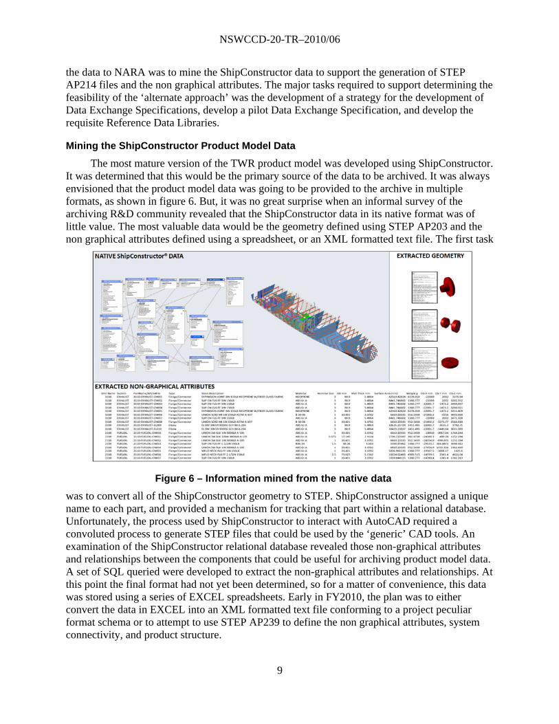
Mining the ShipConstructor Product Model Data
The most mature version of the TWR product model was developed using ShipConstructor. It was determined that this would be the primary source of the data to be archived. It was always envisioned that the product model data was going to be provided to the archive in multiple formats, as shown in figure 6. But, it was no great surprise when an informal survey of the archiving R&D community revealed that the ShipConstructor data in its native format was of little value. The most valuable data would be the geometry defined using STEP AP203 and the non graphical attributes defined using a spreadsheet, or an XML formatted text file. The first task
was to convert all of the ShipConstructor geometry to STEP. ShipConstructor assigned a unique name to each part, and provided a mechanism for tracking that part within a relational database. Unfortunately, the process used by ShipConstructor to interact with AutoCAD required a convoluted process to generate STEP files that could be used by the ‘generic’ CAD tools. An examination of the ShipConstructor relational database revealed those non-graphical attributes and relationships between the components that could be useful for archiving product model data. A set of SQL queried were developed to extract the non-graphical attributes and relationships. At this point the final format had not yet been determined, so for a matter of convenience, this data was stored using a series of EXCEL spreadsheets. Early in FY2010, the plan was to either convert the data in EXCEL into an XML formatted text file conforming to a project peculiar format schema or to attempt to use STEP AP239 to define the non graphical attributes, system connectivity, and product structure.
Figure 6 – Information mined from the native data
NSWCCD-20-TR–2010/06
10
AP214 / AP239 Feasibility
Application Protocols designed specifically to meet the information requirements of a specific industry or domain has not been successful. An examination of the ‘state of the industry’ in data exchange has revealed that the neutral file data exchange technology developed to meet the needs of the shipbuilding industry is not available. An informal survey of government, commercial shipbuilders, and product model software suppliers reveals this capability will not be available in the foreseeable future. One of the flaws with the shipbuilding STEP Application Protocols has been an instability of the schema. The schema has been tweaked every time it has been used. Each pilot program has either modified the schema in the name of improvement or has limited the entities that could be used. It has been held by some that the answer to this problem is a modularized, or object oriented approach. The National Shipbuilding Research Program funded by the Program Executive Offices Submarines, Carriers and Ships proposed and started development of the Ship Common Information Model (SCIM) and establish core requirements for an Integrated Product Data Environment.5 The purpose of the SCIM is to define a common ontology to be referenced by all future shipbuilding IPDEs for data exchange and application integration. The concern is the SCIM effort is defining a subset, further constraining the application protocol. Clearly, a different approach to enabling data exchange must be investigated. The use of a more generic approach is appealing. For this to work, it may require a developmental effort for each data exchange program. However, this has been a trait of most STEP pilot projects undertaken by the marine industry to date. The more generic approach appears to have the potential of reducing the amount of effort required to implement a digital data exchange program within a production environment. This led to the decision to use AP203 and AP214 to define geometry, and AP239 for non geometric data.
As the ship product model matured during the earlier years of the NARA project, it became obvious that the shipbuilding STEP application protocols were not appropriate for several reasons. Lack of availability of commercial off the shelf translators were a concern, but surprisingly was not the motivating reason for pursuing an alternate approach. The final reason was the potential users of the TWR product model data developed for the NARA project were predominantly from outside the marine industry and had an immediate need for the data.
Approach
An evaluation of the options for representing the product model developed during the NARA project in a neutral format is usually the first step when designing a digital data exchange program. In this case the decision to use AP203 and AP239 had already been made.
To prepare for the development of an implementation of AP203 and AP239 the product data and the uses of the data was evaluated. This resulted in an inventory of the types of other information to be delivered to NARA (e.g. photographs and brochures), Product Model data defined using ShipConstructor, and CAD data defined using a myriad of CAD systems. A convenient key was selected to relate all of the other technical data to the product data. Once this was completed the ShipConstructor non graphical data was evaluated, and then extracted to a format that could be of value to the team implementing AP239. At this point all of the other technical data, the non graphical product model data, and the geometric component of the
5 NSRP ASE, NSRP Navy Product Data Initiative Integrated Product Data Environment (IPDE)
Specification”, June, 30 2008.

NSWCCD-20-TR–2010/06
11
product model can be stored, but it is not yet in a standard format. The next step was to document the information, product structure, and relationships that should be preserved. This combination of the data and how it can be used was able to serve as an informal requirements specification to support the definition of a data exchange specification.
A team consisting of leaders in the subject of Product Life Cycle Support using STEP were assembled to develop the infrastructure required to support the application of Data Exchange Specifications, Reference Data Libraries, and AP 239 to represent ship product model data. This team then took these requirements, and generated the documentation required to define a data exchange specification. This process included the development of an information model and the data definitions. The team planned on developing the data exchange specification, templates, and reference data. Those products as shown in figure 7 would then be used in conjunction with the
extracted data to generate neutral product data suitable for delivery to NARA.
The scope of the data exchange set encompasses breakdowns, parts, distributed system relationships, and documents. Three breakdowns are to be defined: system, zonal, and compartment. Parts are to be defined within the context of a breakdown and include connect points to support placement in a distributed system.
Data Exchange Specification
The Data Exchange Specification that was developed directly addresses the types of data that were created for the NARA program. The Ship Long Term Data Retention (ShipLTDR) DEX was developed to support the immediate needs of the archiving project, but with an eye toward future reuse by other projects wherever possible. The resultant AP239 DEX and related Reference Data Library should support other sources of data for archive, in addition to that provided from the ShipConstructor source CAD system, and the original TWR841 design documentation. The business requirements as supported by the DEX are included within the formal DEX documentation. The DEX is a collection of the entities defined in the STEP AP239 information model. Typically, the DEX can support a complete data exchange to support a specific process. The DEX is defined using entities that are in AP239. Typically, the entities are
Figure 7 – Data Exchange Specification Architecture

NSWCCD-20-TR–2010/06
12
selected such that they are in functional groups that can be built up to define the DEX. The ShipLTDR DEX is defined using a combination of existing templates and templates that were specifically developed to support this data exchange. The TWR data extracted from the Ship Constructor database were very helpful in understanding the information requirements for the DEX. Since the DEX is industry generic, the templates developed for the NARA project would be useful in many other DEX’s. The reference data is shipbuilding specific in most areas, but not all, and could also be used by other DEX’s. During this exercise, issues in the DEX development process were discovered and potential improvements were identified. The templates that were developed for the NARA project will be made available for general use. The templates used to define the ShipLTDR DEX are shown in figure 8.
The following provides a high-level overview of the business concepts and ship data object types supported by the DEX.
Zonal Breakdown identifies a division of a ship based on physical locations to divide the area of design to a manageable size, or to identify the portion of the ship that will be modularly constructed into increasingly large units and blocks. This subdivision can be called a Design Zone or Unit. Numerous Design Zones or Units are commonly identified within a ship, each one identified by a code (e.g., 2310, 2210, 3110, 2110, and 1110).
Figure 8 – ShipLTDR DEX templates

NSWCCD-20-TR–2010/06
13
Part represents a component within the ship model and is identified through a part number. A Part can be a standard part in a catalog, an occurrence of a catalog part that has been placed within the global coordinate space of the ship product model, or a part in the ship’s product model not previously defined in a standard part catalog.
Document represents data associated with parts, systems, or the entire Ship. Drawings, 3D models, and technical manuals are all examples of documents. Documents are associated with their id, name, and storage location, and can optionally be assigned a SWBS classification.
Compartment Breakdown is a type of Zonal_breakdown and is a logical structure that identies all of the physical Compartments on a Ship. Compartments can be enclosed within other Compartments. Parts can be related to the Compartment that they belong to through their association to a Compartment item in the Compartment Breakdown.
System Breakdown identifies a breakdown of the ship based on the structural systems that make up the ship (e.g., hull, decks, and bulkheads), and the engineering systems that support the ship’s operation and mission (e.g., piping systems, HVAC systems, command and control systems). Each system in the breakdown is identified through the Ship Work Breakdown Structure (SWBS) code, which is defined by NAVSEA Instruction 4790.1B. Systems can be composed of sub-systems. Parts, and connections between the parts, can be classified according to the system that they belong to. Documents, such as System Diagrams, can be related to the System that they represent.
Parts belonging to the ship’s distributed systems, such as the piping system, can be connected together. End represents a point on the part to which another part can be connected. Each end is identified by a name. The location of the end to which another part can connect is represented as a point in a Cartesian coordinate system, typically the Ship’s global coordinate system. Connection is used to logically connect two end points together.
Documents can be related to other documents. For example, in the case of a 3D model of a part, a document in a standard data format (e.g., ISO 10303-214) can be related to the equivalent document in the proprietary data format (e.g., Autocad .dwg). A document, such as a drawing, can be composed of several sheets, where sheets have their own id, name, and storage location. Documents (e.g., System Diagrams) can be classified by a SWBS code.
The team opined that the standard DEX documentation is necessary, but incomplete for implementers. For instance, the standard DEX documentation does not include example data files. Besides example data files as test cases, implementers would like to have a usage guide and example diagrams. For example, a diagram that shows the instances example with sample data in it would be useful. In the STEP community, these are not part of the standard, but developed with implementers and published in something like an implementers forum.
Ship Reference Data Library
Data Exchange Specifications specify the relationships between generic objects, and refer to a Reference Data Library (RDL) for classification of the applicable object types and properties about those objects. This allows simple update of the RDL to support additional business objects and properties. The initial RDL developed for the Ship LTDR DEX supports the data contained in the Navy’s TWR841 product model that was developed using ShipConstructor software, as well as all component classes, system types, and properties documented in the Navy’s LEAPS V4.1 FOCUS Product Meta Model.

NSWCCD-20-TR–2010/06
14
Domain entities, relationships, and properties were harvested for PLCS from the Ship Common Information Model using techniques that were developed for a Navy Small Business Innovative Research funded project. Reeper utilities from sourceforge were used to harvest domain entities, relationships, and properties from STEP application reference models. Ruby scripts from Future STEP Architecture project were also used to develop the reference data. Reference Data Classifications were developed for the Ship Work Breakdown Structure (SWBS), zone codes, part numbers, piping, and HVAC.
Additional Benefits
This cooperative research with NARA over the past five years reaped several benefits for the Navy and Department of Defense. NARA funding was not used to support any of the projects described herein
LEAPS IGES Bulk Loader
The development of a tool that could bulk load IGES files into LEAPS and can relate those IGES geometry files with a limited set of property data defined in an XML formatted text file provided benefit to the Ship to Shore Connector contract design.
Torpedo Weapons Retriever CAD Model
The availability of the Torpedo Weapons Retriever CAD and product model, even in its current relatively unmanaged state was very well accepted by various organizations involved in engineering analysis and simulation. The majority of these organizations are using the data to support research, development, and testing efforts within their organization. Some of these organizations are using the data as the basis for marketing materials and to support demonstrations because the data is marine industry specific, and because it is approved for public release with unlimited distribution. It is difficult to estimate how many organizations directly involved with engineering analysis, visualization, and modeling and simulation have accessed this data. However, the data delivered to the NSRP bulletin board (www.isetools.org) developed as a direct result of NARA funding has been accessed over 2000 times.
The Torpedo Weapons Retriever CAD model was also used by NUWC Newport to support planning and design of experiments for the Torpedo Weapons Retriever.
We continually have planning questions for future experiments that use the 841 as a craft of opportunity. A lot of the experiments have nothing to do with the ramp, and some do. We're always trying to figure out if some prototype piece of gear can be handled by the onboard crane, fit on the available deck space, and then be deployed/recovered either down the ramp or over the tail with the A-frame. By having good quality solid models of the 841, we can better plan and strategize our future testing. Most all of the prototypes we are building and testing exist first in the virtual world. By have a virtual 841 we can readily simulate the shipboard
NSWCCD-20-TR–2010/06
15
logistics of future planned testing and find the show stoppers well before actually testing commences.6
The Ship Constructor product model of the TWR 841 was made available to Art Anderson Associates who was conducting a Small Business Innovative Research project to integrate Ship Constructor and SKM’s electrical tool analysis software through a proposed product to be called Shipboard Electrical Analysis – Production (SEAPro). Their goal was to reflect the SKM electrical design by passing equipment and connectivity data to the Ship Constructor CAD model and reflect changes made in Ship Constructor as equipment trade-offs and procurement decisions were made back into the SKM electrical analysis tool to validate the changes. This Navy SBIR project directly benefited from the use of the TWR-49 product model through reduced man-hour expenditure since it was not necessary to create a Ship Constructor model from scratch. The end of project briefing took place at an National Shipbuilding Research Program meeting which had shipbuilding industry and U. S. Navy personnel in attendance.
Small Business Innovative Research
The results of NARA research was a key element in submitting a request for an SBIR proposal. The proposal was accepted and two contracts have been awarded. The objective of the SBIR is to develop processes and interface tools to enable the bi-directional transfer of product model data between shipbuilders during the design and construction life cycle phases, and the delivery of the as-built product model to the Navy. ATA Engineering Incorporated proposed to develop processes and interface tools to enable the bi-directional transfer of product model data between shipbuilders during the design and construction life cycle phases, and the delivery of the as-built product model to the Navy using a set of proprietary data exchange classes, independent of any standard but built around the LEAPS data models, since LEAPS is the target data repository. CostVision Incorporated proposed to develop processes and interface tools to enable the bi-directional transfer of product model data between shipbuilders during the design and construction life cycle phases, and the delivery of the as-built product model to the Navy using PLCS DEX (Product Life Cycle Support Data EXchange Specification) open source technology, and extend them to the integrated shipbuilding design and analysis environment.
Interagency Communication
The NARA research fostered communications with other organizations having similar problems and goals. These include the US Army Tank and Automotive Command, PDES Inc. NIST, and EuroSTEP. Most importantly involvement in this project drew the interest of the DoD Engineering Drawing and Modeling Working Group.
Epilogue
The work performed during the first five years provided an example of ship product model data encompassing the type of information used in early stage design, ships arrangements, detail design, and construction. Data spanned the entire spectrum including that used to synthesize a new design, collected during a ship check, and developed to support modifications to ships and
6 Boyd, Scott, Assistance with 120TR841 CAD Data, email received 27 Jan 2010, NUWC Newport

NSWCCD-20-TR–2010/06
16
ships systems. The data generated by this NARA project provided value to Universities, software vendors, DoD Activities, and other government agencies.
During the final year of the NARA project there were several accomplishments, and unfortunately a setback. The effort required to develop a data exchange specification and translation software was greater than estimated. There simply was not enough funding nor time to complete the DEX and developed a translator. The primary problem with developing a translator was time. The project had to be completed before October 2010. The development of the DEX was not completed until late September, and translator development could not begin until the DEX was complete. Since it was not possible to perform the conversions to deliver the non graphical attributes, product structure, and system connections using STEP AP239, within the period of performance of the interagency agreement, a decision was made to split those resources between DEX development and manually converting the proprietary ShipConstructor data to a form that would be more useful to NARA researchers. It is important to emphasize all of the information required to relate intelligence to the geometric part, define the product structure, and define system connectivity has been extracted from the ShipConstructor database to EXCEL spreadsheets. That data in conjunction with the approximately 3000 STEP AP214 can be converted into useful data by NARA researchers. It will also be a straight forward task to generate the AP239 files. Cataloged and organized all data developed over the span of the NARA project such that it can be delivered in accordance with instructions provided by the NARA Center for Advanced Systems and Technologies. A STEP AP214 file was generated for every TWR part modeled in ShipConstructor. Non-graphical attributes were extracted for every TWR part modeled in ShipConstructor. Data exchange specifications and reference data libraries were developed to represent the ship product model and other technical data developed during the NARA project.
And there are plans to continue our partnership with NARA during FY2011 and beyond. Issues related to S1000D will be addressed, beginning with the integration of three dimensional product model data in technical publications. Technologies for improving the relationship between S1000D Data Modules and Product Data Models will be identified and further developed. Ensuring that the life-cycle model exchange and archival between Industry, Armed Services and NARA can be satisfied as per U.S.C. 44 § 3103. Develop test cases to demonstrate the relationship between S1000D Data Modules and Product Data Models. Identify acquisition language needed to support the connection/relationship between S1000D Data Modules and Product Data Models.