long-term stability analysis of goaf area in longwall...
TRANSCRIPT

JME Journal of Mining & Environment, Vol.9, No.1, 2018, 169-182.
DOI: 10.22044/jme.2017.5950.1408
Long-term stability analysis of goaf area in longwall mining using
minimum potential energy theory
M. Rezaei
Department of Mining Engineering, Faculty of Engineering, University of Kurdistan, Sanandaj, Iran
Received 29 June 2017; received in revised form 14 August 2017; accepted 19 August 2017
Corresponding author: [email protected] (M. Rezaei).
Abstract
Estimation of the height of caved and fractured zones above a longwall panel along with the stability
conditions of the goaf area are very crucial to determine the abutment stresses, ground subsidence, and face
support as well as designing the surrounding gates and intervening pillars. In this work, the height of caving-
fracturing zone above the mined panel is considered as the height of destressed zone (HDZ). The long-term
estimation of this height plays a key role in the accurate determination of maximum ground surface
subsidence and the amount of transferred loads towards the neighbouring solid sections. This paper presents
a new stability analysis model of caved material system in the goaf area. For this aim, a theoretical energy-
based model of HDZ determination in long-term condition is developed. Then the stability condition of the
caved material system is investigated using the principle of minimum potential energy. On the basis of the
actual data gathered from the literature, the unstable time period of the caved material system is also
calculated. Moreover, the effects of time- and temperature-related parameters and constant coefficients as
well as their inherent relations with HDZ are evaluated. Furthermore, sensitivity analysis shows that the two
temperature-related constants material constant and time are the most effective variables in HDZ, and the
slope of material hardening is the least effective one. The estimated HDZ and the stability time of the caved
materials can be successfully applied to determine the induced stress and the maximum surface subsidence,
respectively, due to longwall mining.
Keywords: Longwall Mining, Height of Destressed Zone, Caved Material System, Minimum Potential
Energy, Stability Time.
1. Introduction
Longwall mining method is one of the most
popular and productive underground methods
used in the mining industry. This method is
suitable for extraction of the relatively thick,
sub-horizontal, and uniform coal (rock) seams.
The main objective of this method application is
high productivity along with providing the
acceptable safety conditions. However, the mining
efficiency exclusively depends upon the stability
of the stopes, gates, surrounding access tunnels,
and pillars. The stability of these structures is also
related to both the roof cave-in performance and
the interaction of the caved materials with the roof
rock strata. Subsequent to the seam extraction and
advancing the hydraulic jacks, the immediate roof
in the mined area collapses and caves at the rear
of the working face. The downward movement of
the roof rock strata then gradually extends
upwards and will cause the disturbed roof strata to
become destressed. Thus the overburden pressure
above the destressed zone will be redistributed in
the rock mass surrounding the longwall panels
and directed to the front and rib-side abutments
[1-7].
Generally, there are several research approaches
to study the progressive fracturing and caving of
the panel roof rock strata including in-situ
measurement as well as physical, empirical,
numerical, and analytical modeling. Despite being
worthy, each of these methods has defects that

Rezaei/ Journal of Mining & Environment, Vol.9, No.1, 2018
170
have been described in detail by Rezaei and others
[3]. Due to these restrictions and simplicity of the
analytical modeling, a new theoretical
energy-based model with further incorporated
effective parameters is suggested in this work to
evaluate the combined height of caving and
fracturing zones above the longwall gobs. Here, a
combination of the height of caving and fracturing
zones is considered as the height of destressed
zone (HDZ). Beyond this height, the overburden
pressure will be transferred towards the adjacent
solid sections. Therefore, HDZ has a vital role in
the amount of transferrable loads to the front
abutment, adjacent access tunnels, pillars, and
panel rib-sides. Thus to suitably evaluate the
amount of transferrable loads to the adjacent gates
and the intervening pillars, the amount of HDZ
must be estimated [3]. In addition, evaluating the
induced ground subsidence is a critical topic in
longwall mining, which is affected by the caving
and fracturing of the roof rock strata [8]. Actually,
the complete/total value of HDZ can be achieved
while the caved material system would be stable.
On the other hand, the ground subsidence
phenomenon will be stopped by stabilization of
the caved material system. Therefore, the stability
time of the caved material system is very
important in determination of maximum HDZ and
ground surface subsidence due to longwall
mining.
The main aim of this work was to investigate
HDZ above the longwall gobs in long-term
conditions, and to estimate the stability time of the
caved material system. For this purpose, the time-
dependent analytical determination of HDZ is
firstly described. Then the stability time of the
caved material system is calculated based upon
the principle of minimum potential energy. Unlike
the past studies, the geometrical and
geomechanical properties of roof rock strata as
well as the pressure, time, and
temperature-dependent parameters of the caved
materials were considered in the HDZ prediction
simultaneously. Finally, the effects of time and
temperature-related parameters on HDZ and the
stability time of the caved material systems were
evaluated.
2. Background
2.1. Distributed zones above mined panel
After coal extraction in longwall mining, the roof
rock strata are allowed to be fractured and caved
in the mined area (called the goaf area). This
process causes disturbance of the original in-situ
stress regime and the hydraulic conductivity. By
progressive in extraction, the fracturing and
caving phenomena of roof strata gradually extend
upwards and will cause the disturbed roof strata to
become destressed. Prediction of HDZ above the
longwall gobs plays an important role in
determining the transferred loads towards the
front abutments and panel rib-sides in which the
gates and pillars are situated. For this purpose,
many researchers have investigated the behavior
of working roof, process of gradual upward
movement, and determination of the height of
caving and fracturing zones. These issues have
recently been discussed by some investigators
[1-3], in which the previous related investigations
have also been referred. According to these, three
zones of disturbance have been identified above
the mined panel (Figure 1). These zones include
the caved, fractured, and continuous deformation
zones [9]. As it can be seen in Figure 1, these
zone can reach 20, 20-50, and more than 50 times
the extracted seam thickness (mining height),
respectively. However, extension of each zone
depends on the geological and geomechanical
conditions of overburden strata including the
strength properties of rocks, in-situ stress,
thickness of seam (rock) and overburden, and type
and nature of the strata [10].
Figure 1. Three movement zones in overburden due to longwall mining [10].

Rezaei/ Journal of Mining & Environment, Vol.9, No.1, 2018
171
2.2. Literature review
Comprehensive literature review about the
disturbed zones over the goaf area was conducted
in detail [2, 3, 6, 7]. However, for brevity, only
the most important and related ones of the older
studies were reviewed. Instead, the new
investigations in the field of roof rock failure
strata and its relationship with the ground surface
subsidence are discussed in more detail. Roof rock
behaviour above the goaf area was studied by
Eavenson [11] for the first time. He believed that
the inner-burden shear failure during multiple
seam extraction in longwall mining extended to
the ground surface. However, Denkhaus [12]
proved that the maximum HDZ would be equal to
50% and 63% of the depth of cover above the
panel for rocks with sufficient and insufficient
cohesion, respectively. Some other researchers
have proposed different models to calculate the
heights of caved and fractured/destressed zones
above the goaf area in terms of the coefficient of
extracted coal seam thickness or mining height.
For example, Ropski and Lama [13] have shown
that the primary and secondary caving zones
extend to a height of 3-3·5 times the extracted
coal seam thickness. Palchik [14] believed that the
thickness of the fractured zone varied from 20 to
100 times the extracted seam thickness. Palchik
[15] has found that the maximum heights of
interconnected fractures and separate horizontal
fracture zones reach 19-41 and 53-92 times the
extracted coal seam thickness, respectively.
According to Zhimin and others [16], the height
of the fractured zone was obtained to be
14.33–17.71 and 16.04 times the mining thickness
from in-situ measurements and numerical
modeling, respectively. Zhang and others [17]
have investigated the overburden fracture
evolution laws in mining a very thick coal seam
under water-rich roof using the numerical
modeling. Their finding proved that the height of
the fractured zone in the overburden strata ranged
from 18.66 to 47.66 times the extraction seam
height. Gao and others [18] have developed a
numerical approach to simulate the progressive
caving of strata above a longwall panel. Their
results show that the fractures extend
approximately 40 m into the roof.
In addition to the above reviewed references, the
newly related research works that have been
conducted in the latest recent years (2015, 2016,
and 2017) are examined here in detail. The
horizontal displacement distribution caused by a
single advancing longwall panel excavation has
been evaluated by Tajduś [19]. He assumed that
the value of the horizontal displacement was
proportional to the slope of subsidence value. Xue
and others [20] have analyzed the movement and
fracture of overlying strata based on the
experimental analysis. They concluded that the
maximum height of caving, fracturing, and
bending zones were equal to 7.5, 25, and 25 times
the mining height, respectively. Based on the
in-situ measurement and numerical and theoretical
modeling, Bai and others [21] have studied the
roof deformation and failure characteristics in
advancing longwall working face, and proposed a
dynamic mechanical model of the roof structure.
Ming-he and others [22] have developed a
numerical model to evaluate the stress distribution
around the longwall face based on the caving
height zone. The research conclusion has
highlighted that the height of caving zone is the
main parameter effective on the coefficient of
stress concentration around the longwall panel.
The in-situ measurements performed by Palchik
[23] showed that the maximum height of caved
zone could reach 20 times the mining height.
According to a conceptual model proposed by Qu
and others [24], the maximum relative height of
key stratum is about 20.7 times the extracted seam
thickness.
According to a coalface failure model proposed
by Jiachen and others [25], due to longwall panel
extraction, the height of caving zone increases
with increase in the mining height. According to
Meng and others [26], the ratios of the average
caving-fracturing zone height to the extracted coal
seam thickness in the Daliuta coal mine from the
in-situ tests, physical modeling, and numerical
simulation are equal to 20.3, 22.8, and 19.4,
respectively. Theoretical evaluation of the
abutment pressure in longwall coal mining
conducted by Zhu and others [27] based on the
analysis of load transfer mechanisms of key
stratum (KS) showed the importance of roof rock
strata disturbed zone in transferred load to the
sides and front abutments. Yu and others [28]
have evaluated the stress changes and deformation
of coal pillars and gateroads affected by the
mining-induced stress based on the in-situ
measurements. Accordingly, they have concluded
that the adjacent panel extraction plays a crucial
role in the main deformation and damage of the
surrounding gate roads. Xie and Xu [29] have
studied the key stratum above the mined panel,
and evaluated its effect on the mining abutment
pressure of a coal seam. They proved that the
abutment pressure of the field model with a key
stratum was 42% higher than that of the model

Rezaei/ Journal of Mining & Environment, Vol.9, No.1, 2018
172
without any key stratum. Rezaei [6] has developed
a new neural network model for estimation of the
height of caving–fracturing zone over the
longwall gobs and evaluation of the effect of
geomechanical parameters on this height. Rezaei
and others [7] have proposed an optimum ANN
model to determine HDZ over the mined panel in
longwall mining. Beside the determination of
disturbed zones above the mined panel, the
relationship between the ground subsidence and
overburden failure and also time-dependent
failure and deformation of roof strata time have
been investigated by some researchers [30-34].
These showed that numerous factors affected the
ground subsidence due to mining operation
including the mining method, mining depth, ore
thickness, stope size, dip angle of ore body,
geological structure, nature of overburden and
water contents, roof supports, etc. [34]. However,
there is no formulated analytical basis to show the
relation between the ground subsidence and
disturbed zones above the mined panel in log-term
condition.
Considering the above literature review, it is
obvious that there are various in-situ
measurements, empirical, mathematical,
numerical, and physical models to predict the
height of disturbing zones above the longwall
gobs. In all the previous investigations, the effects
of time- and temperature-related parameters were
ignored in the evaluation of the height of caving
and fracturing zones. To overcome these
shortages, a time-dependent energy model for
evaluation of HDZ above the longwall gobs is
described in the current study. Furthermore, the
stability of the caved material system is discussed
for subsidence estimation subjects. The main
application of the estimation of the caved material
system stability time is in the prediction of
maximum occurred ground subsidence in surface
due to longwall mining. It is obvious that the
ground subsidence would be stable while the
caved material system is stable. Indeed,
determination of the time stability of the caved
material system helps the ground subsidence
occurrence period determination. Knowledge of
the maximum surface subsidence and it
occurrence period helps engineers in designing the
preventive supports and supply the safety
requirements.
3. Stability analysis model
3.1. Time-dependent calculation of HDZ
Energy consideration in longwall mining, and
consequently, determination of HDZ above the
longwall panel in long-term and short-term
conditions have already been discussed by Rezaei
and others [3-5]. However, HDZ in the long-term
condition was calculated by Rezaei and others [5]
recalled here in order to develop a new procedure
for evaluation of the stability time of the caved
material system as well as estimation of the effect
of time- and temperature-related parameters on
HDZ. According to Rezaei and others [3], coal
seam extraction in longwall mining causes
disturbance of the energy balance within a system
enclosing mine openings and surrounding rocks.
This leads to release the stored strain energy in the
mined seam. However, this released energy will
not be lost according to the principle of energy
survival but transfer from one equilibrium state to
another. Indeed, the released energy is consumed
in the fracturing, caving, and destressing of the
over roof rock layers. Accordingly, it is concluded
that the total stored strain energy in the mined
seam (Um) is equal to the strain energy stored in
the roof destressed zone (Ud), as shown in the
following equation:
m dU U (1)
By the assumption that there exist no permanent
supports in longwall mining, i.e. ignoring the
effect of body forces, here, the total stored strain
energy in the mined seam (Um) is calculated by
the Salamon [35] equation, as follows:
dSuTU
mS
p
i
p
im )()(
2
1 (2)
where p
iT , p
iu , and Sm are the stress or traction
vector acting on a surface, and the component of
the displacement vector before starting the mining
and mined layer area, respectively. These
parameters are computed as follow [35]:
(p)
i v
2(p)
i
T H
(1 )(1 2 ) Hu
2(1 )E
(3)
where σv, E, γ, H, and ν are the initial stress due to
the overburden pressure, rock mass elastic
modulus, rock mass unit weight, depth of cove,
and rock mass Poisson ratio, respectively.
Substitution of Eq. (3) into Eq. (2) leads to:
mS
m dAHE
HU 2
2
)1(2
)21)(1(
(4)

Rezaei/ Journal of Mining & Environment, Vol.9, No.1, 2018
173
In Eq. (4), the integral term is the moment of
inertia of surface Sm with respect to the plane of
ground surface. Thus according to the
parallel-axis theorem in statics:
2
0
2 DAIdAHI m
Sm
(5)
where I0 is the moment of inertia of the mined
area (panel) cross-section with respect to a
horizontal line across its centre of gravity, Am is
the cross-section of the mined panel, H is the
depth of cove, and D is the vertical distance from
the panel centre of gravity to the ground surface.
With regard to the rectangular cross-section of the
mined panel, Am, I0, and D are calculated as
follow:
m w s
3
w s0
s
A L h
L hI
12
D H h / 2
(6)
where Lw and hs are the panel width and extracted
coal seam thickness, respectively.
When Eqs. (5) and (6) are substituted into Eq. (4),
the final equation of the total stored energy in the
extracted coal seam is obtained:
2
2m v s
m s
(1 )(1 2 ) A hU ( H Hh )
2(1 )E 3
(7)
The strain energy stored in the roof destressed
zone (Ud) is generally composed of elastic strain
energy (UE) and viscoplastic strain energy (UV).
VEd UUU (8)
The non-linear rheological constitutive model
introduced by Zhang and others [36] is utilized to
investigate the rheological properties of the caved
materials and calculate the components of Ud. In
this model, the elastic modulus (E), coefficient of
viscosity (μ), and threshold value of stress (σs) are
considered based upon the modified Bingham
model [36]. According to this model, the stress of
caved materials before and after the yield point
(threshold value of stress) is calculated as follows:
s
s
at
K
eE
>,
0
(9)
where E0 is the initial elastic modulus, a is the
material constant, t is the pressure time of caved
materials, ε is the strain of caved materials, λ is
the slope of material hardening stage, and K is the
coefficient that is calculated by the following
equation:
s
at
Bt
eEK
0
1 (10)
where B = 1/η0Cα; η0 is the initial coefficient of
viscosity; and C, μ, and α are the material
constants related to temperature.
To calculate the elastic strain energy of the caved
materials within the destressed zone (UE), the
common equation of strain energy is used. If the
destressed zone above the longwall panel is
considered as a separate system, its absorbed
elastic strain energy can be calculated as follows:
h
E AdhdVU02
1
2
1 (11)
where σ is the applied stress on the caved
materials, ε is the strain occurring under the
applied stress, h is the height of the caved
materials within the destressed zone, and A is the
unit surface of the system. Here, Ad is considered
as the unit surface of the destressed zone, which is
equal to the panel width multiplied by the unit
length of longwall panel (Ad = Lw × 1m). After
completion of the caving process, the caved
materials are thoroughly compressed, and then the
total height of caved materials is equivalent to
HDZ (h = Hd). Thus Eq. (11) can be modified to:
ddE HAU 2
1 (12)
In Eq. (9), the caved material system has the
elastic and viscoplastic properties when σ ≤ σs and
σ≥ σs, respectively. Accordingly, the elastic and
viscoplastic components of strain energy are
calculated based on its related stress in this
equation. Therefore, substitution of the elastic and
viscoplastic parts of Eq. (9) into Eq. (12) lead to
calculate the elastic strain energy (UE) and
viscoplastic strain energy (UV) stored in the roof
destressed zone, as follow:
2
2
1dd
at
E HAEeU (13)
ddV HAK
U )22
(22
(14)
Instead of the strain of caved materials, this
equation can be instituted; it was developed by
Salamon [37] to describe the stress-strain behavior
of caved materials:

Rezaei/ Journal of Mining & Environment, Vol.9, No.1, 2018
174
][m
c
c
E
(15)
where σc is the uniaxial compressive strength of
caved materials and εm is the maximum possible
strain of the caved materials. εm depends on the
bulking factor (b), and can be determined using
the following equation [38]:
b
bm
1 (16)
By substituting Eqs. (15) and (16), Eqs. (13) and
(14) could be modified as follow:
2
2
])1(
[2
b
bE
HAEeU
c
cdd
at
E
(17)
][
])1(
[2 2
2
BtEe
b
bE
HAU sat
c
cddV
(18)
Now the total strain energy stored in the roof
destressed zone (Ud) is achieved by substituting
Eqs. (17) and (18) into Eq. (8) in the following
form:
]2[
])1(
[2 2
2
BtEe
b
bE
HAU sat
c
cddd
(19)
Finally, if Eqs. (19) and (7) are substituted into
Eq. (1), HDZ in time-dependent condition is
calculated as follows:
22m v s
s
d 2atd c s
2c
(1 )(1 2 ) A hH Hh
(1 )E 3H
A[2Ee ]
b Bt[E ]
(b 1)
(20)
3.2. Stability time of goaf
Estimation of stability time of the caved material
systems is very important to determine the
maximum surface subsidence due to longwall
mining. In this research work, stability analysis of
the proposed time-dependent energy model is
conducted based on the principle of minimum
potential energy of the caved materials system. It
is obvious that the total potential energy of the
caved material structure (Π) is composed of strain
energy (Ud) and external work (W):
WUd (21)
The total strain energy stored in the roof
destressed zone (Ud) was calculated in the
previous section, as shown in Eq. (19). Thus only
the external work (W) is calculated in this section.
Assuming that P is the pressure of roof rocks and
u is the deformation of caved materials, the
external work of roof rocks upon the caved
materials (W) can be written as:
puW (22)
Here, the deformation parameter (u) is selected as
the state variable. For matching the external work
and strain energy equations, the stress (σc) existing
in Eq. (19) must be written in terms of
deformation. To do so, stress and strain can be
defined according to the stress-strain behaviour of
caved materials in rheological constitutive model
by Zhang and others [36], as the following
equations:
K/ (23)
hu / (24)
Given that the discussed height in this study is the
height of destressed zone in long-term condition
(Hd), we can write:
dHu / (25)
Replacing Eq. (25) into Eq. (23) leads to:
KH
u
d
c (26)
Substitution of Eq. (26) into the stress parameter
of Eq. (19) leads to:
2
atd
d2 2
d
d
A u 1U [Ee ]
bu K2H K [E ]
H K(b 1)
(27)
When Eqs. (27) and (22) are substituted into Eq.
(21), the total energy of structure (Π) is achieved
as follows:
2atd
2 2
d
d
A u 1[Ee ] pu
bu K2H K [E ]
H K(b 1)
(28)
According to the principle of minimum potential
energy, the system is stable when the energy of
the system reaches a minimum. If δ2Π ≥ 0 and δΠ
= 0, the energy of the system reaches a minimum

Rezaei/ Journal of Mining & Environment, Vol.9, No.1, 2018
175
(δ is the derivative sign). In the case of δ2Π ˂ 0
and δΠ ≠ 0, the energy of the system cannot reach
a minimum. These concepts are used in order to
calculate the stability time of the caved material
system in longwall mining. Accordingly, the
second derivative of total energy of structure (Π)
or Eq. (28) is achieved as:
2 at 2d
2 2
d
A 1[Ee ] ( u)
KH K E
(29)
In our investigation, the state of transition from
the instability to stability (δ2Π = 0) is considered
as the stability time of the caved materials system.
Therefore, the time of stability of caved material
system can be obtained when δ2Π = 0. Since K ˃
0 in Eq. (29), we can write:
01 KKEe at (30)
Substitution of Eq. (10) into Eq. (29) and
rearranging it lead to:
at at 2 at
s s2 Ee (Ee ) Bt Bt Ee (31)
To solve Eq. (31) and obtain the stability time of
the caved material structure, a graphical method
can be used. For this purpose, Eq. (31) is divided
into two functions, as follows:
at at 2 at
sf (t) 2 Ee (Ee ) Bt Bt Ee (32)
stg )( (33)
The intersection of the graphs of the above two
equations will be the stability time of the caved
material structure (ts). Actually, these two graphs
and their intersection value could be applied to
obtain the stability time of caved materials that
practically outlined in the following sub-section.
3.3. Validation of proposed model
In order to validate the proposed model, the
particular experimental data was utilized to plot
the graphs of the above-mentioned two functions
(given in Eqs. (32) and (33)) and obtain the
corresponding stability time. As an engineering
example, the values of the measured experimental
data conducted by Zhang and others [36] were
applied for drawing the graphs and calculation of
the stability time of the caved material structure
(ts). These measured experimental datasets are
presented in Table 1. Also the geometrical and
geomechanical parameters are kept constant
according to the in-situ measurements conducted
by RafiqulIslam and others [39], as shown in
Table 2. On the basis of the experimental data
given in Table 1, Zhang and others [36] have
calculated the stability time of the caved materials
using the analytical model and compared the
results obtained with the observations in practice.
Therefore, the results of the proposed model in
this research work can be compared with the
result of the above research work as a comparison
basis for the validation aim. Considering this data,
the graphs of f(t) and g(t) were plotted and shown
in Figure 2. According to this figure, the stability
time of the caved material structure is equal to
1.643 years. Thus from the first caving period
until 1.643 years later, the caved material system
is unstable and HDZ increases consequently.
After this time, the system will be stable, and the
additional subsidence will not occur in the ground
surface. The stability time calculated by Zhang
and others [36] was 1.51 years. As it can be seen
from this comparison, the results of the current
research work are in a good agreement with the
results obtained by Zhang and others [36], which
conforms well to the observations in practice.
Thus it can be concluded that the proposed model
can be successfully applied for the long-term
stability analysis of goaf area and calculation of
the stability time of the caved materials.
Moreover, this model and its corresponding
computed stability time can be linked to the
maximum ground surface subsidence calculation
in the future research works.
Table 1. Experimental parameters used in plotting graphs [36].
σs (MPa) E (MPa) B µ α λ a
20 59 1.24 2 0.3 3 1
Table 2. Geometrical and geomechanical parameters and corresponding mean caving and fracturing zone used
in current study calculations [39].
H (m) Lw (m) γ (KN/m3) E (GPa) ν σc (MPa) b hs (m) HDZ (m)
290 120 2.7 3.5 0.22 50 1.5 3.5 29.5

Rezaei/ Journal of Mining & Environment, Vol.9, No.1, 2018
176
Figure 2. Graphs of f(t) and g(t) to obtain stability time of caved material structure.
4. Parametric study
Beside the geometrical and geomechanical
parameters, the time and temperature parameters
are also the most important variables, and are very
crucial in the stability analysis of the goaf area.
Knowledge of the height of the caved, fractured,
and destressed zone along with the sustainability
of the goaf area is very crucial during the time and
extraction phases. Also compression of the caved
material causes increase in temperature, which
affects the bulking and compaction characteristics
of the caved material. These may affect the
instability of the caved material system and other
related objects, i.e. roof failure and ground
subsidence. Despite this great importance, this
issue was rarely investigated by previous
researchers. Thus the effects of pressure and time
of caved materials and temperature-related
parameters are discussed in detail here.
Accordingly, variations in HDZ versus material
constant (a), slope of materials hardening stage
(λ), temperature-related parameters of α, C, and μ,
threshold value of stress (σs), initial coefficient of
viscosity (η0), and pressure time of caved
materials (t) are shown in Figures 3-10,
respectively. In these figures, the relative
influence of each parameter on HDZ is identified
by varying the desired parameter and maintaining
fixed values for the other parameters according to
Table 1.
Figure 3. Relationship between HDZ and material constant.

Rezaei/ Journal of Mining & Environment, Vol.9, No.1, 2018
177
Figure 4. Relationship between HDZ and slope of material hardening.
Figure 5. Relationship between HDZ and temperature-related parameter (α).
Figure 6. Relationship between HDZ and temperature-related parameter (C).
Rezaei/ Journal of Mining & Environment, Vol.9, No.1, 2018
178
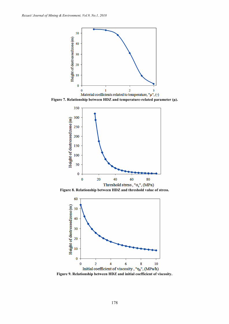
Figure 7. Relationship between HDZ and temperature-related parameter (μ).
Figure 8. Relationship between HDZ and threshold value of stress.
Figure 9. Relationship between HDZ and initial coefficient of viscosity.

Rezaei/ Journal of Mining & Environment, Vol.9, No.1, 2018
179
Figure 10. Relationship between HDZ and pressure time of caved materials.
According to Figure 3, the material constant has a
direct relation with HDZ. Indeed, the material
constant (a) is a positive material constant, named
the softening parameter that describes the
softening characteristic of the material or rocks. If
the softening parameter of caved material
increases, the compression capacity of the
material will increase. Therefore, with increase in
the material constant, more compression will
occur, and then further roof caving will take place.
As it can be seen in Figure 4, when the slope of
material hardening increases, HDZ increases by a
linear relation. It is obvious that the higher value
of slope of material hardening means that the
caved materials have a more compression
capability. This causes an additional caving, and
thus a further value of HDZ. Figures 5-7 indicate
that the temperature-related parameters including
α, C, and μ are in non-linear inverse relations with
HDZ. It is known that increasing the temperature
and its related parameters increases the amount of
fluid, and lowers the strain rate of the caved
material. Decreasing the strain rate lowers the
compaction of the caved material, and thus
decreases the caving process of the roof rock
strata. Thus HDZ will increase with increase in
the temperature-related parameters including α, C,
and μ. As it can be seen in Figure 8, a higher value
for threshold stress leads to a lower HDZ. The
threshold value of stress normally depends on the
compressive strength of caved materials.
Obviously, materials with high compressive and
threshold stress values have fewer tendencies to
cave, and as a result, HDZ will decrease. It can be
concluded from Figure 9 that the higher the initial
coefficient of viscosity, the lower is HDZ. This
proves the fact that if the coefficient of viscosity
of caved rocks increases, less compression of
them will occur. Thus the amount of roof caving
decreases, and thus HDZ will be less. Finally,
Figure 10 demonstrates that HDZ has a direct
relation with the pressure time of caved materials.
It is clear that over the time, the caved material
will be further compressed, and therefore, enough
space will be provided for more caving. As a
result, the height of the destressed zone increases
over the time. In addition, the semi-fractured or
suspended rocks will cave over the time that
causes the increase in HDZ.
As a general conclusion of the parametric study, it
can be concluded that the time and
temperature-related parameters considerably
affect HDZ (see Figures 5-7 and 10). This issue
has been neglected in the previous research works,
which can influence the estimated HDZ and other
related variables, especially in time-dependent
situations. Therefore, the proposed model could
be preferred in long-term conditions.
5. Sensitivity analysis
In this section, sensitivity analysis is conducted to
estimate the most and least effective parameters
on HDZ among the time- and temperature-related
parameters. Sensitivity analysis could be
performed in two different ways, i.e. novel and
traditional procedures. In novel procedures,
available equations and techniques such as cosine
amplitude method [40-42] could be applied for
this purpose. However, in the traditional methods,
the influence of an input variable on the
corresponding output could be achieved by
systematic changing of it and keeping fixed values
for the other inputs of the model. The latest
procedure was used in this work for the sensitivity

Rezaei/ Journal of Mining & Environment, Vol.9, No.1, 2018
180
objects. To do so, to achieve the influence of each
parameter on HDZ, other parameters were
assumed constant, according to the experimental
values given in Table 1 in the first stage. Then the
value of the considered input changed
systematically from -30% to +30% (i.e. three
values) of its actual value in Table 1 and
corresponding HDZ calculated. This process was
performed for all of the time and
temperature-related parameters, and the graphs
obtained along with their gradients are
demonstrated in Figure 11. The graph with higher
gradient shows a more impact of its corresponding
input on the output. As it can be seen in Figure 11,
temperature-related parameters (α and µ), material
constant (a), and time (t) are the most effective
variables on the HDZ, while the slope of material
hardening (λ) is the least effective one on it.
Figure 11. Sensitivity analysis results of time- and temperature-related parameters.
6. Conclusions
A new analytical model was developed in this
research work for the stability analysis of the
longwall goaf area. To do so, a time-independent
model was developed for the height of destressed
zone (HDZ) above the mined panel. Then the
stability time of the caved material system in
longwall mining was analyzed based upon the
principle of minimum potential energy.
Eventually, the parametric study and sensitivity
analysis were performed in order to evaluate the
relation of time- and temperature-related
parameters with HDZ, and determine the effective
parameters. The results obtained showed that the
material constant, slope of material hardening
stage, and pressure time of caved materials have
direct influences on HDZ. On the other hand, the
temperature-related parameters (α, C, and μ),
threshold stress, and initial coefficient of viscosity
have inverse influences on HDZ. Moreover,
temperature-related parameters, i.e. α and µ,
material constant, and time are the most effective
parameters on HDZ, and the slope of material
hardening is the least effective one. As seen, time-
and temperature-dependent parameters have
significant effects on HDZ and should not be
neglected in the modeling. A general consequence
of the new proposed analytical model compared to
the previous ones is that it incorporates the effects
of pressure time and temperature-related
parameters of caved materials on HDZ along with
the estimation of the stability time of the goaf.
The long-term evaluation of HDZ time plays an
important role in an accurate estimation of
transferred loads towards the gates and pillars
during the anytime of mining operation lifetime.
In addition, prediction of the stability time of
caved materials helps the exact determination of
maximum ground surface subsidence due to
longwall mining. However, these topic points
require further investigations and validation and
recommendations for future works.
References [1]. Majdi, A., Hassani, F.P. and Yousef Nasiri, M.
(2012). Prediction of the height of destressed zone

Rezaei/ Journal of Mining & Environment, Vol.9, No.1, 2018
181
above the mined panel roof in longwall coal mining.
International Journal of Coal Geology. 62: 62-72.
[2]. Majdi, A. and Rezaei, M. (2013). Application of
artificial neural networks for predicting the height of
destressed zone above the mined panel in longwall coal
mining. 47th
U.S. Rock Mechanics/Geomechanics
Symposium. San Francisco. California. USA. pp. 1665-
1673.
[3]. Rezaei, M., Hossaini, M.F. and Majdi, A. (2015).
A time-independent energy model to determine the
height of destressed zone above the mined panel in
longwall coal mining. Tunnelling and Underground
Space Technology. 47: 81-92.
[4]. Rezaei, M., Hossaini, M.F. and Majdi, A. (2015).
Determination of longwall mining-induced stress using
the strain energy method. Rock Mechanics and Rock
Engineering. 48: 2421-2433.
[5]. Rezaei, M., Hossaini, M.F. and Majdi, A. (2015).
Development of a time-dependent energy model to
calculate the mining-induced stress over gates and
pillars. Journal of Rock Mechanics and Geotechnical
Engineering. 7: 306-317.
[6]. Rezaei, M. (2016). Development of an intelligent
model to estimate the height of caving-fracturing zone
over the longwall gobs. Neural Computing &
Applications. doi: 10.1007/s00521-016-2809-3.
[7]. Rezaei, M., Farouq Hossaini, M., Majdi, A. and
Najmoddini, I. (2017). Determination of the height of
destressed zone above the mined panel: An ANN
model. International Journal of Mining and Geo-
Engineering. 51 (1): 1-7.
[8]. Ghabraie, B., Ghabraie, K., Ren, G. and Smith, J.
(2017). Numerical modelling of multistage caving
processes: insights from multi-seam longwall mining-
induced subsidence. International Journal for
Numerical and Analytical Methods in Geomechanics.
41: 959-975.
[9]. Chekan, G.J. and Listak, J.M. (1993). Design
practices for multiple-seam longwall mines.
Information circular/1993 (No. PB-94-113545/XAB;
BUMINES-IC-9360). Bureau of Mines. Pittsburgh. PA
(United States). Pittsburgh Research Center.
[10]. Palchik, V. (2010). Experimental investigation of
apertures of mining-induced horizontal fractures.
International Journal of Rock Mechanics & Mining
Sciences. 47: 502-508.
[11]. Eavenson, H. (1923). Mining an upper
bituminous seam after a lower seam has been extracted.
Transaction of AIME. 69: 398-405.
[12]. Denkhaus, H.G. (1964). Critical review of strata
movement theories and their application to practical
problems. Journal of the Southern African Institute of
Mining and Metallurgy. 64 (8): 310-332.
[13]. Ropski, S.T. and Lama, R.D. (1973). Subsidence
in the near-vicinity of a longwall face. International
Journal of Rock Mechanics and Mining Sciences
abstract. 10 (2): 105-106.
[14]. Palchik, V. (1989). Analytical and empirical
prognosis of rock foliation in rock masses. Journal of
Coal Ukraine. 7: 45-46.
[15]. Palchik, V. (2003). Formation of fractured zones
in overburden due to longwall mining. Journal of
Environmental Geology. 44 (1): 28-38.
[16]. Zhimin, X., Yajun, S., Qinghong, D., Guowei, Z.
and Shi, L. (2010). Predicting the height of water-flow
fractured zone during coal mining under the Xiaolangdi
Reservoir. Mining Science and Technology. 20: 434-
438.
[17]. Zhang, Y., Tu, S., Bai, Q. and Li, J. (2013).
Overburden fracture evolution laws and water-
controlling technologies in mining very thick coal seam
under water-rich roof. International Journal of Mining
Science and Technology. 23 (5): 693-700.
[18]. Gao, F., Stead, D. and Coggan, J. (2014).
Evaluation of coal longwall caving characteristics
using an innovative UDEC Trigon approach.
Computers and Geotechnics. 55: 448-460.
[19]. Tajduś, K. (2015). Analysis of horizontal
displacement distribution caused by single advancing
longwall panel excavation. Journal of Rock Mechanics
and Geotechnical Engineering. 7: 395-403.
[20]. Xue, J., Wang, H., Zhou, W., Ren, B., Duan, C.
and Deng, D. (2015). Experimental research on
overlying strata movement and fracture evolution in
pillarless stress-relief mining. International Journal of
Coal Science & Technology. 2: 38-45.
[21]. Bai, J.B., Shen, W.L., Guo, G.L., Wang, X.Y. and
Yu, Y. (2015). Roof deformation, failure
characteristics, and preventive techniques of gob-side
entry driving heading adjacent to the advancing
working face. Rock Mechanics and Rock Engineering.
48: 2447-2458.
[22]. Ju, M.H., Li, X.H., Yao, Q.L., Li, D.W., Chong,
Z.H. and Zhou, J. (2015). Numerical investigation into
effect of rear barrier pillar on stress distribution around
a longwall face. Journal of Central South University.
22 (11): 4372-4384.
[23]. Palchik, V. (2015). Bulking factors and extents of
caved zones in weathered overburden of shallow
abandoned underground workings. International
Journal of Rock Mechanics & Mining Sciences. 79:
227-240.
[24]. Qu, Q., Xu, J., Wu, R., Qin, W. and Hu, G.
(2015). Three-zone characterisation of coupled strata
and gas behaviour in multi-seam mining. International
Journal of Rock Mechanics & Mining Sciences. 78: 91-
98.

Rezaei/ Journal of Mining & Environment, Vol.9, No.1, 2018
182
[25]. Jiachen, W., Shengli, Y. and Dezhong, K. (2016).
Failure mechanism and control technology of longwall
coalface in large-cutting-height mining method.
International Journal of Mining Science and
Technology. 26: 111-118.
[26]. Meng, Z., Shi, X. and Li, G. (2016). Deformation,
failure and permeability of coal-bearing strata during
longwall mining. Engineering Geology. 208: 69-80.
[27]. Zhu, S., Yu, F. and Jiang, F. (2016).
Determination of abutment pressure in coal mines with
extremely thick alluvium stratum: a typical kind of
rockburst mines in china. Rock Mechanics and Rock
Engineering. 49: 1943-1952.
[28]. Yu, B., Zhang Z., Kuang, T. and Liu, J. (2016).
Stress changes and deformation monitoring of longwall
coal pillars located in weak ground. Rock Mechanics
and Rock Engineering. 49: 3293-3305.
[29]. Xie, J.L. and Xu, J.L. (2017). Effect of key
stratum on the mining abutment pressure of a coal
seam. Geosciences Journal. 21: 267-276.
[30]. Xiao, W., Hu, Z., Chugh, Y.P. and Zhao, Y.
(2014). Dynamic subsidence simulation and topsoil
removal strategy in high groundwater table and
underground coal mining area: a case study in
Shandong Province. International Journal of Mining,
Reclamation and Environment. 28: 250-263.
[31]. Villegas, T. and Nordlund, E. (2012). Time-
dependent movements of the hangingwall at the
Kiirunavaara mine. International Journal of Mining,
Reclamation and Environment. 26: 119-133.
[32]. Sui, W., Zhang, D., Chi, Z.C., Wu, Z. and Zhao,
Q. (2015). Environmental implications of mitigating
overburden failure and subsidences using paste-like
backfill mining: a case study. International Journal of
Mining, Reclamation and Environment. 29: 521-543.
[33]. Hindistan, M.A. and Yetisen, H. (2012).
Assessment of subsidence at Çayırhan lignite mine
using aerial photogrammetry. International Journal of
Mining, Reclamation and Environment. 26: 351-365.
[34]. Deng, J., Bian, L., Li, X.B., Zhao, G.Y. and
Wang, X.M. (2006). Analysis of factors and
countermeasures of mining subsidence in Kaiyang
Phosphorus Mine. Journal of Central South University
of Technology. 13 (6): 733-737.
[35]. Salamon, M.D.G. (1984). Energy considerations
in rock mechanics: fundamental results fundamental
results. The South African Institute of Mining
Metallurgy. 84 (8): 233-246.
[36]. Zhang, T., Ma, M., Wang, H. and Xu, H. (2011).
A nonlinear rheological model of backfill material for
retaining roadways and the analysis of its stability.
Mining Science and Technology (China). 21: 543-546.
[37]. Salamon, M.D.G. (1990). Mechanism of caving
in longwall coal mining MDG Salamon. In Rock
Mechanics Contributions and Challenges: Proceedings
of the 31st US Symposium on Rock Mechanics. CRC
Press. pp. 161-168.
[38]. Yavu, H. (2004). An estimation method for cover
pressure re-establishment distance and pressure
distribution in the goaf of longwall coal mines.
International Journal of Rock Mechanics & Mining
Sciences. 41 (2): 193-205.
[39]. Rafiqulislam, M.D., Hayashi, D. and
Kamruzzaman, A.B.M. (2009). Finite element
modeling of stress distributions and problems for
multi-slice longwall mining in Bangladesh, with
special reference to the Barapukuria coal mine.
International Journal of Coal Geology. 78: 91-109.
[40]. Khoshjavan, S., Mazlumi, M., Rezai, B. and
Rezai, M. (2010). Estimation of hardgrove grindability
index (HGI) based on the coal chemical properties
using artificial neural networks. Oriental Journal of
Chemistry. 26: 1271-1280.
[41]. Sayadi, A.R., Tavassoli, S.M.M., Monjezi, M.
and Rezaei, M. (2014). Application of neural networks
to predict net present value in mining projects. Arabian
Journal of Geosciences. 7: 1067-1072.
[42]. Rajabi, M., Rahmannejad, R., Rezaei, M. and
Ganjalipour, K. (2017). Evaluation of the maximum
horizontal displacement around the power station
caverns using artificial neural network. Tunnelling and
Underground Space Technology. 64: 51-60.

6931اول، سال م، شماره نهدوره زیست، پژوهشی معدن و محیط -/ نشریه علمیرضائی
ناحیه تخریب شده در معدنکاری جبهه کار طوالنی با استفاده از نظریه حداقل انرژی مدت درازتحلیل پایداری
پتانسیل
یمحمد رضائ
گروه مهندسی معدن، دانشکده مهندسی، دانشگاه کردستان، ایران
63/8/9162، پذیرش 93/1/9162ارسال
[email protected]نویسنده مسئول مکاتبات:
چکیده:
هوای اطورا ، نشسوت های تخریب و شکست شده باالی پهنه جبهه کار طوالنی و شرایط پایداری منطقه تخریب شده به منظوور ارزیوابی تون ناحیهبرآورد ارتفاع
هوا شوده شکست به عنوان ناحیوه ر -ها بسیار حیاتی است. تخمین دراز مدت ارتفاع ناحیه تخریبهای اطرا و پایهسطح زمین، پایداری جبهه کار، طراحی ورودی
مدلی جدیود بورای از تن دارای نقشی اساسی در تعیین دقیق حداکثر نشست سطح زمین و مقدار بار انتقالی به ساختارهای اطرا است. از این رو در این تحقیق
یوین ارتفواع زون رهوا از تون در دراز تحلیل پایداری مواد تخریب شده توسعه داده شده است. در مدل پیشنهادی، ابتدا مدل تحلیلی بر پایه روش انرژی بورای تع
هوای واقعوی دهمدت تعیین شده و سپس شرایط پایداری ناحیه تخریب شده با استفاده از اصل حداقل انرژی پتانسیل مورد بررسی قرار گرفتوه اسوت. بور اسوا دا
یابی به درک صحیحی از نق پارامترهوای بر این، به منظور دست آوری شده از منابع منتشر شده قبلی، زمان ناپایداری این سیستم محاسبه شده است. عالوهجمع
ا استفاده از تحلیل حساسویت مختلف، ارتباط ارتفاع ناحیه رها شده از تن با متغیرهای زمان و ضرایب ثابت وابسته به دما مورد ارزیابی قرار گرفته است. در انتها ب
ته اولیه کم تأثیرترین پارامتر بر ارتفاع زون رها از تن است. از ارتفاع ناحیوه رهوا شوده از تون و زموان مشخص شد که زمان مؤثرترین پارامتر و ضریب ویسکوزی
در تعیین تن ناشی از معدنکاری و حداکثر نشست ایجاد شده در سطح زمین استفاده کرد.توان پایداری برآورد شده به ترتیب می
اقل انرژی پتانسیل، زمان پایداری.ه رها شده از تن ، سیستم مواد تخریب شده، حداستخراج جبهه کار طوالنی، ناحی کلمات کلیدی: