longana, m., yu, h., jalalvand, m., wisnom, m., & potter
TRANSCRIPT

Longana, M., Yu, H., Jalalvand, M., Wisnom, M., & Potter, K. (2017).Aligned discontinuous intermingled reclaimed/virgin carbon fibre compositesfor high performance and pseudo-ductile behaviour in interlaminated carbon-glass hybrids. Composites Science and Technology, 143, 13-21. DOI:10.1016/j.compscitech.2017.02.028
Publisher's PDF, also known as Version of record
License (if available):CC BY
Link to published version (if available):10.1016/j.compscitech.2017.02.028
Link to publication record in Explore Bristol ResearchPDF-document
University of Bristol - Explore Bristol ResearchGeneral rights
This document is made available in accordance with publisher policies. Please cite only the publishedversion using the reference above. Full terms of use are available:http://www.bristol.ac.uk/pure/about/ebr-terms.html

Aligned discontinuous intermingled reclaimed/virgin carbon fibrecomposites for high performance and pseudo-ductile behaviour ininterlaminated carbon-glass hybrids
Marco L. Longana*, HaNa Yu, Meisam Jalavand, Michael R. Wisnom, Kevin D. PotterACCIS, University of Bristol, Bristol, BS8 1TR, UK
a r t i c l e i n f o
Article history:Received 5 December 2016Received in revised form22 February 2017Accepted 27 February 2017Available online 28 February 2017
Keywords:RecyclingShort-fibre compositesHybrid composites
a b s t r a c t
Highly aligned intermingled fibre composites are produced from reclaimed and virgin carbon fibres usingthe High Performance Discontinuous Fibre (HiPerDiF) method. The stiffness and strength characteristicsof these materials are studied as a function of the reclaimed to virgin fibres ratio. Interlaminated hybridcomposites with discontinuous carbon fibre preforms sandwiched between continuous glass fibres aredesigned to demonstrate pseudo-ductility and allow investigation of the effect of the mixing ratio ofreclaimed and virgin carbon fibres on the nonlinear stress-strain curve shape. The pseudo-ductilebehaviour is explained by adapting the Damage Mode Map to describe the failure process of inter-laminated hybrid specimens with different low elongation material strength. It is concluded that theHiPerDiF method is a valuable platform to remanufacture reclaimed carbon fibres into a high perfor-mance and potentially economical value recycled composite material. The Damage Mode Maps can beused to optimise the pseudo-ductile response of the interlaminated hybrid material.© 2017 The Authors. Published by Elsevier Ltd. This is an open access article under the CC BY license
(http://creativecommons.org/licenses/by/4.0/).
1. Introduction
The wide spread of carbon fibres reinforced polymers (CFRPs) invarious engineering and industrial sectors over the last decadesposes the challenge of dealing with production waste and end-oflife products, particularly if we consider that carbon fibres pre-serve high intrinsic value. The simple disposal in landfill or incin-eration are increasingly discouraged by the legislation. Themechanical comminution of CFRP and the dispersion of the chop-ped fibres as fillers in replacement for glass fibres limit the deriv-able value. In order to apply the circular economy model tocomposite materials, recycling processes that will allow reclaimingthe fibres with minimal loss of mechanical properties and rema-nufacturing them into high performance materials need to bedeveloped and integrated. A complete review about the technolo-gies to recycle CFRPs for structural applications was presented byPimenta and Pinho [1]. Amongst the fibre reclamation processes itis worth mentioning pyrolysis, i.e. thermochemical decompositionof the matrix at elevated temperatures in an inert environment [2],oxidation in a fluidised bed, i.e. the matrix elimination at high
temperature in oxygen-rich flow [3], chemical recycling in variousreactive media at moderate temperature, e.g. catalytic solutions [4],benzyl alcohol [5], or at higher temperature and pressure in su-percritical fluids [6e9].
Of greater interest for the presented work is, independentlyfrom the fibre recovery process, the remanufacturing of thereclaimed fibres into CFRP and their mechanical response. Whenthe reclamation process preserves the reinforcement architectureof the waste the reclaimed fibres can be used as it is [10]. However,the size-reduction of CFRP waste before reclamation, the fibrebreakage during reclamation and the chopping of the fibres afterreclamation lead to fibres that are fragmented to short lengths. As aresult, the only industrially relevant remanufacturing processes forreclaimed fibres so far are directmoulding techniques, e.g. injectionmoulding [11] and bulkmoulding compound compression [12], andthe compression moulding of intermediate random [13] or alignedmats [14]. However, to deliver improved recycled materials, a highfibre alignment is the key factor to increase the fibre volume frac-tion, and consequently the performances of recycled composites[15,16]. Various techniques, already used for the alignment of shortfibres, have been taken in consideration for the remanufacturing ofreclaimed carbon fibres. A modified papermaking technique wasapplied to reclaimed fibres from the University of Nottingham* Corresponding author.
E-mail address: [email protected] (M.L. Longana).
Contents lists available at ScienceDirect
Composites Science and Technology
journal homepage: http: / /www.elsevier .com/locate/compscitech
http://dx.doi.org/10.1016/j.compscitech.2017.02.0280266-3538/© 2017 The Authors. Published by Elsevier Ltd. This is an open access article under the CC BY license (http://creativecommons.org/licenses/by/4.0/).
Composites Science and Technology 143 (2017) 13e21

research group [14,17,18] reaching 80% of the theoretical alignmentvalue and a fibre volume fraction of 45% with a moulding pressureof 100 bar. Wong et al. [19] proposed the use of a centrifugalalignment rig, which uses a dispersion of fibres in a viscous mediaaccelerated through a convergent nozzle installed in a rotatingdrum, as remanufacturing technique for reclaimed carbon fibres.An alignment level of 90% was obtained using 5 mm fibres. Thesame authors [19] worked on a hydrodynamic spinning process of aviscous fibre suspension. Janney et al. [20] developed the ThreeDimensional Engineered Preform Process (3-DEP) adding multiplemotions control to a pulp moulding process tool and therefore thecontrol of fibre areal weight and orientation.
The HiPerDiF method, developed at the University of Bristol[21], has proven to be an effective way to manufacture compositematerials with high levels of alignment from discontinuous fibres.This unique fibre orientation mechanism uses the momentumchange of a water-fibre suspension to align the fibres. It was pre-viously noted that tensile modulus, strength and failure strain ofaligned discontinuous fibre composites produced with the HiPer-DiF method were close to those of continuous fibre compositesprovided that the fibres are accurately aligned and their length issufficiently long compared to the critical fibre length [22,23]. Theuse of the HiPerDiF method allows the production of high perfor-mance recycled carbon fibre composites from reclaimed discon-tinuous carbon fibres. Therefore, this method enables the efficientrecovery of value from end-of-life components and productionwastes, and is well placed in the developing of a supply and pro-cessing chain of recycled carbon fibre composites and in a circulareconomy model, as demonstrated also by Ref. [25].
As described in Ref. [22] the HiPerDiF method can be used toproduce hybrid composites with different configurations, theseallowed obtaining pseudo-ductile behaviour from glass-carbon andcarbon-carbon intermingled composite [23,24], this can be furthertailored if intermingled composites are coupled with continuousglass fibres to generate interlaminated composites [24].
The present work is aimed at evaluating the effect of reclaimedfibres on the mechanical properties of intermingled and inter-laminated hybrid composites. In a first stage, the performances ofintermingled reclaimed and virgin carbon discontinuous fibre (rCFand vCF respectively) composites are assessed. A good knowledgeabout the mechanical properties of combined reclaimed/virgincarbon fibre composite will help to maximise the use of reclaimedcarbon fibres taking account the related economic advantages.Subsequently, plies of intermingled discontinuous fibres, withdifferent ratios of rCF/vCF, are interlayered in continuous glass/epoxy prepreg layers to study the effect on tensile behaviour ofcarbon/glass hybrid composites.
2. The HiPerDiF method
The HiPerDiF method is a novel technique that allows aligningdiscontinuous fibres [21,22]. The technique was originally devel-oped to study the behaviour of aligned discontinuous fibre com-posites as a function of fibre type, length and alignment levelwithin the HiPerDuCT (High Performance Ductile CompositeTechnology) project [23]. The working principle exploits the sud-den momentum change of a jet of fibres suspended in waterdirected in a narrow gap between parallel plates as shown in Fig. 1.
In the HiPerDiF process, the fibres are dispersed in a liquidmedium (water) that is accelerated through a nozzle to partiallyalign the fibres. The fibre suspension jet is directed to the orien-tation head, which is comprised of parallel plates with a control-lable gap. The fibres are aligned transversely to the suspension jetby a suddenmomentum change of the liquid, provided that the gapis a maximum of 1/3 the fibre length. Subsequently, the fibres fall
on a perforated conveyor belt that is running parallel to the narrowgap direction; a suction plate, placed underneath the belt, removesthe water maintaining the fibre orientation. The aligned fibre pre-form is then dried with infrared radiations to allow the resinimpregnation process. This method allowed obtaining highly-aligned and high fibre volume fraction discontinuous CFRPs: forcomposites with a 41% fibre volume fraction (vf), 65% of fibres werein the range of ±3�to perfect alignment, and in the case of com-posite specimens with 55% of vf, 67% of fibres were in the range of±3� to perfect alignment [22]. Moreover, using high strength fibres(Young's Modulus 225 GPa, Strength 4350 MPa), mechanicalproperties comparable to those of continuous fibres were achieved:a Young's Modulus of 80.6 GPa and a strength of 816 MPa for 41% ofvf and a Young's Modulus of 115 GPa and a strength of 1509 MPa for55% of vf [22]. In addition, the HiPerDiF method enabled intimatelymixing two or more different fibre types in one preform due to itsintrinsic manufacturing capabilities [23,24].
One of the exceptional potentials of HiPerDiF technology is thatit makes it possible to achieve high mechanical properties and ahigh value by remanufacturing reclaimed carbon fibres into highly-aligned, high-performances unidirectional composites [24]. Thesepreforms have also the potential to achieve pseudo-ductilebehaviour. To do so, two approaches are considered in this paper:(i) intermingled rCF/vCF composites and (ii) interlaminated hybridcomposites with an embedded layer of intermingled rCF/vCFsandwiched between continuous glass fibre layers.
3. Experiment
3.1. Materials
High tensile strength virgin carbon fibres (C124, TohoTENAX,[26]) and reclaimed carbon fibres (AS4, Hexcel) from a M56 resincomposite with the pyrolysis “cycle B” process defined by Pimentaand Pinho in Ref. [27] were used. The mechanical properties aresummarised in Table 1.
The intermingled preforms with rCF/vCF are coupled with aMTM49-3 epoxy resin film [28] and partially impregnated byapplying a pressure of 30 bar at a temperature of 60 �C. The me-chanical properties of the continuous E- and S-glass compositelayers used for the interlaminated hybrid specimens, measuredwith tensile tests conducted with the specimens shown in Fig. 2,are summarised in Table 2. Please note that these glass/epoxycomposites weremanufactured in a closedmould and therefore thefibre volume fractionwas about 15% higher than one obtained withspecimens manufactured on an open tool-plate. For the inter-laminated hybrid composites, the rCF/vCF preform was impreg-nated during the curing process by the resin excess from thecontinuous glass fibre prepreg.
3.2. Specimen preparation
The specimens were prepared by vacuum bag moulding. The
Fig. 1. HiPerDiF fibre alignment mechanism, front view and cross-section (A-A0) [22].
M.L. Longana et al. / Composites Science and Technology 143 (2017) 13e2114

intermingled fibre composites were cured in an autoclave for135 min at a temperature of 135 �C and a pressure of 6 bar. Theinterlaminated composites were cured according to the curing cy-cle of the continuous glass prepreg, i.e. 90 min at a temperature of125 �C and a pressure of 6 bar. Burrs at all edges of cured sampleswere gently removed. GFRP end-tabs were bonded with Hunts-mann Araldite 2014-1 adhesive. A schematic of the specimen isshown in Fig. 2. The nominal thickness of the intermingled rCF/vCFcomposites, manufactured with four plies of discontinuous carbonfibres, is 0.22 mm. The nominal thickness of the interlaminatedglass/carbon composites, manufactured with the stacking sequence[ContG2/DiscC2/ContG2], where ContG represents a continuousglass layers and DiscC an aligned discontinuous carbon fibre pre-forms, is 0.50 mm for the ones with E-glass and 0.56 mm for theones with S-glass. A view of the cross-section is shown in Fig. 2.
3.3. Test method
Tensile tests were performed on an electro-mechanical testingmachine with a cross-head displacement speed of 1 mm/min. Theload was measured with a 10 kN load cell (Shimadzu, Japan) andthe strainwas measured with a video extensometer (Imetrum, UK).A white speckle pattern over a black background was spray paintedon the specimens to allow the strain measurement with the videoextensometer. The gauge length for the strain measurement wasslightly less than 50 mm.
3.4. Intermingled rCF/vCF composites fibre volume fractioncalculation
To be able to better interpret the stiffness and strength data ofthe interlaminated specimens, it is necessary to measure the fibrevolume fraction (Vf). The estimation of the Vf through imageanalysis of microscopy images of the cross-section was deemedunreliable as it is affected by the fibre misalignment and dependenton the arbitrary grey threshold value chosen to distinguish fibreandmatrix. In a first attempt, the resin burn-off method, codified inthe ASTMD3171 standard, was used. This proved to be unreliable asthe discontinuous fibres were blown away by the internal air cir-culation in the furnace. Considering the low weight of each spec-imen, even the loss of a small amount of fibre during the resin burn-off compromises the fibre volume fraction measurement. It wastherefore decided to estimate a nominal fibre volume fractionVfNom with Equation (1) based on the measured initial stiffness:
VfNom ¼ EMes
h�QfRER þ QfVEV
� (1)
where Qf is the fibre fraction, E is the modulus of the fibres, thesubscript R and V refer to reclaimed and virgin fibre, while EMes isthe measured modulus of the intermingled fibre composite. As in
Ref. [22], the discontinuity andmisalignment of the fibres are takeninto account by the factor h. Considering that the alignment level isindependent of the nature of the fibre and both virgin andreclaimed fibre have the same length, the factor h is assumed to bethe same for all virgin-reclaimed fibre combinations. A value of 0.85was chosen with considerations similar to those discussed by Yuet al. in Ref. [22].
4. Results and discussion
4.1. Intermingled rCF/vCF composites
Batches of 3 specimens with 100% virgin and reclaimed fibres aswell as blends with 10%, 20%, 25%, 30%, 40%, 50%, 60% and 80% ofreclaimed fibres by volume were manufactured and tested. Themeasured tensile modulus as a function of the reclaimed fibrecontent in the composite is summarised in Fig. 3a. The stiffness ofthe rCF/vCF composite materials is fairly independent of the con-tent of reclaimed fibres. The average stiffness is 71.2 GPa and thecoefficient of variation is 7.6% based on all of the specimens withdifferent ratios of rCF/vCF. The relatively high coefficient of varia-tion can be explained considering that a coefficient of variation of7.7% around an average fibre volume fraction of 36% was observed.Furthermore, variations in the fibre volume fraction are reflected inslight variations of the fibre alignment level. The modulus of thespecimens remanufactured with 100% reclaimed fibres is 71.8 GPaand the coefficient of variation is 2.2%, to the authors' bestknowledge this is amongst the highest values of remanufacturedrecycled composites with 3 mm carbon fibres that can be found inthe available literature.
The specimens showed linear-elastic behaviour with brittlefailure. The measured tensile failure strain and strength as a func-tion of the reclaimed fibre ratio in the composite are summarised inFig. 3b. The failure strain and stress, even if affected by the stressconcentration in proximity of the end-tabs where all the specimensfailed, follow an approximately linearly reducing trend between 0%and 50% of reclaimed fibre, and are substantially constant at higherreclaimed fibre ratios. As expected, considering the different natureof the tests, the failure strain of the reclaimed fibre/epoxy com-posites, 0.84%, is higher than the failure strain measured in Ref. [27]on single reclaimed fibres, 0.5%. In particular, it has to be remem-bered that the reclaimed fibre length used to remanufacture thecomposite (3 mm) is lower than the one used to measure the fibreproperties in Ref. [27] (10 mm): this reduces the occurrence ofreclamation-generated defects able to cause fibre failure. Moreoverthe fibres come from end-of-life carbon ‘fabric’ composites: it isreasonable to hypothesize the unit size of fabric weaving pattern tobe much smaller than the 10 mm gauge length of the single fibretest samples, this generates several weakness points caused bydamage in weaving.
It is possible to estimate a failure envelope for the strengthusing the linear or the bilinear rule of mixtures (RoM) developed
Table 1Fibres mechanical properties.
Fibre properties Virgin fibresa Reclaimed fibresb
Fibre type, Manufacturer C124, TohoTENAX AS4, HexcelDiameter [mm] 7 6.5Length [mm] 3 3Density [g/cm3] 1.82 1.79E11 [GPa] 225 230Failure s11 [MPa] 4350 1110Failure ε11 [%] 1.9 0.5
a From manufacturer data sheet [26].b Measured with single fibre tests, a gauge length of 10 mm [27].
Fig. 2. Specimen geometry: top view and cross-section of interlaminated specimen.
M.L. Longana et al. / Composites Science and Technology 143 (2017) 13e21 15

for hybrid composites [29], as shown in Fig. 4. The intermingledrCF/vCF composite can be considered as a hybrid compositeconstituted by two types of fibres with the same stiffness sincethe stiffness difference between rCF and vCF is only 2.2% asshown in Table 1. However, a high difference can be observed inthe failure strains so, in this case, the reclaimed fibres act as thelow elongation and the virgin fibres as the high elongation con-stituent. In terms of strength, it is commonly accepted that thelinear RoM represents the upper bound. While the lower bound isdefined by a bilinear RoM. The bilinear RoM is defined by thecombination of two construction line, the dotted lines in Fig. 4.The linearly decreasing construction line represents the contri-bution of the virgin fibres to the overall strength as a function oftheir amount in the material. The “horizontal” construction linerepresents the strength contribution of the reclaimed fibres. Thestrength for the bilinear RoM, at a given amount of reclaimedfibres, is represented by the higher strength value of the twoconstruction lines.
To be able to draw the rule of mixture curves, the strength isnormalised, using Equation (2), to a common fibre volume fraction(VfCom) value of 60%.
Normalised strength ¼ VfCom �Measured strengthVfNom
(2)
The nominal fibre volume fraction of the intermingled speci-mens (VfNom) was estimated as described in Equation (1), Section3.4, and it was found to vary between 42.5% and 32.4%.
The strength values of both the virgin and reclaimed fibrecomposites used as the input to the RoM of Fig. 5 are obtained fromthe tests results presented above. However, by observing Fig. 3b, itis clear that the failure values for the 0% rCF specimen are incon-gruous with the other data, i.e. are lower than the values obtainedwith 10% rCF and comparable with 20% and 25% rCF. This can beexplained considering that the 0% rCF preforms, despite being ableto generate high fibre volume fraction and high stiffness specimens,present a lower fibre alignment level attributable to mishandlingduring manufacturing. This renders the assumption in Section 3.4not true and it is not possible to normalise the strength value forthe 0% rCF specimens. These results are therefore discarded. To beable to use the RoM envelopes described in Fig. 4, the value of 0%rCF was estimated with a linear regression of the failure stress andstrain values in the interval 10%e50% rCF. The normalised strengthalong with the estimated envelope is shown in Fig. 5a.
Because the composite stiffness as a function of the reclaimedfibre content is constant and the stress-strain curves show a linearelastic-brittle behaviour, the same construction described in Fig. 4for the strength can be applied to the failure strain, as shown inFig. 5b.
In Fig. 5, it can be observed that the strength and the failurestrain are bounded by the RoM envelope and are closer to thebilinear rule of mixtures. In particular, they follow a diminishingtrend, dominated by the virgin fibre properties up to 50% ofreclaimed fibre content. Beyond this threshold, the values aresubstantially constant and correspond to the strength of thereclaimed fibre composite. It is possible to conclude that, in thiscase, quantity higher than 50% of virgin carbon fibres should beadded to composite manufactured from reclaimed fibres to obtainan appreciable increase in the tensile strength and failure strain.However, it would be more efficient to increase the failure stressand strain values of the reclaimed fibre by increasing the lowerstrength boundary, i.e. the “horizontal” bilinear RoM constructionline in Fig. 4, making the addition of virgin fibre not worthwhile atall.
4.2. Interlaminated continuous glass fibre and discontinuous rCF/vCF composites
The interlaminated specimens were manufactured by
Table 2Continuous glass composite properties from tensile test.
E11[GPa]
Failure s11
[MPa]Failure ε11
[%]Ply thickness[mm]
Hexcel E-Glass/913 53.5 1252 2.54 0.097Hexcel S-Glass/913 58.4 1886 3.73 0.112
Fig. 3. Measured mechanical properties of intermingled specimens as a function of thereclaimed fibre content: a) Stiffness; b) Failure stress and strain.
Fig. 4. Definition of linear and bilinear rule of mixtures, adapted from Ref. [30].
M.L. Longana et al. / Composites Science and Technology 143 (2017) 13e2116

embedding two layers of dry intermingled rCF/vCF in the middle offour layers of continuous unidirectional glass fibre prepreg, asdescribed above. Two sets of batches of 3 specimens were tested.One set was manufactured using E-glass and intermingled rCF/vCFpreforms with ratio of 25%, 50% and 75% and rCF only. The other setwas manufactured using S-glass and intermingled rCF/vCF pre-forms with ratio of 30%, 40%, 60% and 80% as well as rCF and vCFonly.
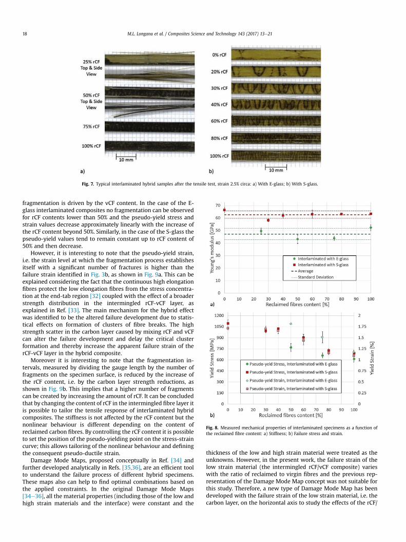
Representative stress-strain curves for the interlaminatedhybrid specimens with E-glass and S-glass are shown in Fig. 6. Fig. 7shows typical tested interlaminated hybrid specimens with E-glassand S-glass and different rCF/vCF ratios, the total tensile strainapplied is 2.5%.
For the interlaminated specimens with E-glass, Fig. 6a, thestress-strain curve of the 25% rCF content shows an almost linear-elastic behaviour up to failure and a brittle fracture. When therCF content is increased, the tensile response becomes non-linearwith knee points appearing when the low elongation material,i.e. the rCF-vCF inner layer, begins to fragment. A transition frombrittle, i.e. failure of the glass layer (Fig. 7a, 25% rCF), to gradualfailure, i.e. fragmentation of the carbon layer (Fig. 7a, 75% and 100%rCF), can be observed here. Of particular interest is that in the caseof 50% rCF of Fig. 7a, both carbon layer fragmentation and glass fibrefailure happen almost simultaneously.
The tensile response of the hybrid laminates made with S-glassis shown in Fig. 6b, a trend similar to E-glass can be observed: largercontents of reclaimed fibres led to earlier deviation from the initiallinear elastic behaviour.
S-glass has a higher stiffness and strength than E-glass, there-fore interlaminated hybrids made with S-glass, shown in Fig. 6b,can withstand higher loads after the full fragmentation of the lowstrain material and can achieve higher elongations before failing. Ofparticular interest in Fig. 6b is the stress-strain curve for the 0% rCF(100% vCF) that presents a sharp change in slope, i.e. a reduction oftangent stiffness, due to onset of damage whereas the other curvesshow a smoother change. The case of 0% rCF (100% vCF) in Fig. 7b issimilar to the case of 25% rCF of Fig. 7a: in this case, however, afterthe single delamination, the continuous S-glass is still able to carrythe load. By increasing the content of rCF in the intermingled layers,and therefore reducing the strain at which the fragmentation starts,it can be observed that the density of the fragmentations in thecarbon layer increases, as clearly shown in Fig. 7b and summarisedbelow.
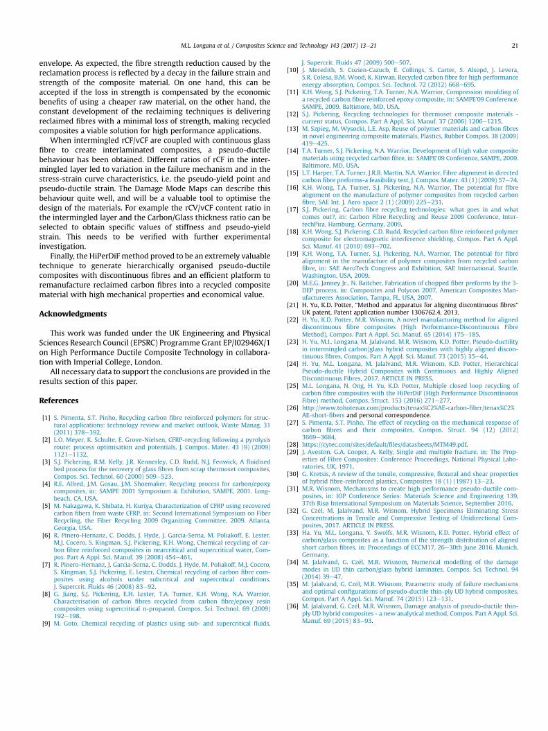
The initial E11 of the two sets of specimens, as a function of thereclaimed fibre content, is shown in Fig. 8a. It can be observed that,as in Fig. 3a, the stiffness is independent of the rCF content. Moreinteresting is to observe the dependence of the pseudo-yieldingstress and strain on the rCF content, as shown in Fig. 8b. Thepseudo-ductile properties of each caseweremeasured based on thedefinition suggested byWisnom et al. [31]. The pseudo-yield stressis defined by the intersection of the stressestrain curve and astraight line with the initial modulus E11 and 0.1% offset from theorigin, this definition is equivalent to the definition of proof stressin metals. The pseudo-yield strain is calculated with Hook's lawusing the initial modulus E11 and the identified pseudo-yield stress.
The beginning of the low elongation material fragmentation isdictated by the rCF content. Moreover, as in Fig. 5, the onset of the
Fig. 5. Rule of Mixture application: a) Normalised strength as a function of thereclaimed fibre content in the composite; b) Measured failure strain as a function ofthe reclaimed fibre content in the composite.
Fig. 6. Stress-strain curves of interlaminated hybrid composites with intermingledrCF/vCF: a) With E-glass; b) With S-glass.
M.L. Longana et al. / Composites Science and Technology 143 (2017) 13e21 17
fragmentation is driven by the vCF content. In the case of the E-glass interlaminated composites no fragmentation can be observedfor rCF contents lower than 50% and the pseudo-yield stress andstrain values decrease approximately linearly with the increase ofthe rCF content beyond 50%. Similarly, in the case of the S-glass thepseudo-yield values tend to remain constant up to rCF content of50% and then decrease.
However, it is interesting to note that the pseudo-yield strain,i.e. the strain level at which the fragmentation process establishesitself with a significant number of fractures is higher than thefailure strain identified in Fig. 3b, as shown in Fig. 9a. This can beexplained considering the fact that the continuous high elongationfibres protect the low elongation fibres from the stress concentra-tion at the end-tab region [32] coupled with the effect of a broaderstrength distribution in the intermingled rCF-vCF layer, asexplained in Ref. [33]. The main mechanism for the hybrid effectwas identified to be the altered failure development due to statis-tical effects on formation of clusters of fibre breaks. The highstrength scatter in the carbon layer caused by mixing rCF and vCFcan alter the failure development and delay the critical clusterformation and thereby increase the apparent failure strain of therCF-vCF layer in the hybrid composite.
Moreover it is interesting to note that the fragmentation in-tervals, measured by dividing the gauge length by the number offragments on the specimen surface, is reduced by the increase ofthe rCF content, i.e. by the carbon layer strength reductions, asshown in Fig. 9b. This implies that a higher number of fragmentscan be created by increasing the amount of rCF. It can be concludedthat by changing the content of rCF in the intermingled fibre layer itis possible to tailor the tensile response of interlaminated hybridcomposites. The stiffness is not affected by the rCF content but thenonlinear behaviour is different depending on the content ofreclaimed carbon fibres. By controlling the rCF content it is possibleto set the position of the pseudo-yielding point on the stress-straincurve; this allows tailoring of the nonlinear behaviour and definingthe consequent pseudo-ductile strain.
Damage Mode Maps, proposed conceptually in Ref. [34] andfurther developed analytically in Refs. [35,36], are an efficient toolto understand the failure process of different hybrid specimens.These maps also can help to find optimal combinations based onthe applied constraints. In the original Damage Mode Maps[34e36], all the material properties (including those of the low andhigh strain materials and the interface) were constant and the
thickness of the low and high strain material were treated as theunknowns. However, in the present work, the failure strain of thelow strain material (the intermingled rCF/vCF composite) varieswith the ratio of reclaimed to virgin fibres and the previous rep-resentation of the Damage Mode Map concept was not suitable forthis study. Therefore, a new type of Damage Mode Map has beendeveloped with the failure strain of the low strain material, i.e. thecarbon layer, on the horizontal axis to study the effects of the rCF/
Fig. 7. Typical interlaminated hybrid samples after the tensile test, strain 2.5% circa: a) With E-glass; b) With S-glass.
Fig. 8. Measured mechanical properties of interlaminated specimens as a function ofthe reclaimed fibre content: a) Stiffness; b) Failure stress and strain.
M.L. Longana et al. / Composites Science and Technology 143 (2017) 13e2118

vCF ratio on the failure mechanism. The absolute thickness of therCF/vCF layer is represented on the vertical axis for a fixed totalglass thickness, in this case 0.39 mm for E-glass, 0.49 mm for S-glass. Such Damage Mode Maps can help to find the optimumcombination of ratios of the recycled to virgin CF content and theabsolute thickness of the rCF/vCF layer embedded between glass/epoxy layers with a pre-known thickness.
Similar to the method presented in Ref. [34], the boundariesbetween different damage process zones are found by equatingpairs of required stress for different failure modes of (i) high strainmaterial failure, (ii) low strain material fragmentation and (iii)delamination. The only difference between the Damage ModeMaps in this paper and those in Refs. [34e36] is the parameters themaps are drawn for (x and y axes variable). More details about themap construction can be found in Refs. [34,36].
Fig. 10 shows the Damage Mode Map for reclaimed-virgin car-bon interlaminated hybrid composites with E-glass and S-glass. Thehorizontal axis shows the failure strain of the rCF/vCF layer and theregistered failure value for each set of specimen is shown on thegraph. These values are slightly higher than those tested with end-tabs and without any outer glass layer shown in Fig. 5b because ofstress concentration elimination around the end tabs, which isextensively discussed in Ref. [32]. For rCF content of 50%, 75% and100% the damage initiation strains coincide with the pseudo-yieldstrains shown in Fig. 8b, and for 25% rCF, which failed suddenly, thedamage initiation strain coincides with the specimen failure strain.
The Damage Mode Map explains the observed change in thefailure process of the tested samples from catastrophic E-glass layerfailure to carbon layer fragmentation. Increasing the rCF/vCF ratio
reduces the failure strain of the low strain material and results inspecimen configurations in the fragmentation region. In the 25%rCF content specimen, the fracture of the discontinuous carbonfibre layer, i.e. the low strain material, causes failure of thecontinuous E-glass layer, as shown in Fig. 7a. In the case of the 75%and 100% rCF content specimens, the discontinuous carbon fibrelayer fragmentation, starting at a lower level of strain, allowsdiffuse carbon fragmentation, as shown in Fig. 7a. Of particularinterest is the case of the 50% rCF that falls very close to theboundary line between the carbon fragmentation and the glassfailure regions in the Damage Mode Map of Fig. 10a and showsfragmentation and glass failure in Fig. 7a. This set of specimenswith50% rCF shows a high variation in its behaviour, as demonstrated byFig. 11: Specimen 1 shows a pseudo-ductile behaviour as shown inFig. 7a while Specimen 2 fails in a brittle manner. In other words,being close to the border lines means that with a slight material orgeometry variability, the failure mode may switch to a differentone.
Because of the higher strength of the S-glass, the predictedfailure process for all tested samples with S-glass is carbon frag-mentation followed by dispersed delamination, as shown inFig. 10b. However, specimens with high ratios of vCF are closer tothe boundary of the single carbon fracture followed by catastrophicdelamination region. The effects of approaching the boundary linebetween “carbon fragmentation & delamination” and “carbonfailure & catastrophic delamination” appear evident in Fig. 9b: thenumber of fragments is reduced and the delaminated area
Fig. 9. Fragmentation behaviour of interlaminated specimens as function of the rCFcontent: a) Comparison with intermingled specimens; b) Fragmentation length.
Fig. 10. Damage Mode Map for interlaminated hybrid composites: a) With E-glass; b)With S-glass.
M.L. Longana et al. / Composites Science and Technology 143 (2017) 13e21 19

increases.By changing the carbon/glass thickness ratio and also the rCF/
vCF ratios, it is possible to increase the hybrid composite stiffnessand optimise the shape of the stress-strain curve to maximise the
pseudo-ductile response. Fig. 12 shows the potential stiffness andpseudo-ductile strain values and the optimum failure strain andabsolute thickness of the rCF/vCR carbon layer. In particular,observing the Damage Mode Map for the interlaminated hybridswith E-glass (Fig. 12a), it can be concluded that by using contents ofrCF over 75% i.e. a rCF/vCF layer failure strain of less than 1.5%, andan absolute carbon thickness of more than 0.15 it is possible tomove into the region of carbon fragmentation and delamination,increasing the total stiffness and the pseudo-ductile strain. For boththe S-glass and the E-glass cases the higher the content of rCF thehigher the possibility to increase the stiffness by increasing thecarbon layer thickness and at the same time maximise the pseudo-ductile strain.
5. Conclusion
This paper demonstrates that not only is it possible to reman-ufacture reclaimed carbon fibre into high mechanical propertiesrecycled composite materials with high mechanical properties, butalso to use rCF to modulate the pseudo-ductile response of inter-laminated hybrid composites.
The failure behaviour of intermingled rCF-vCF composites canbe explained using the linear and bilinear rule of mixtures
Fig. 11. 50% rCF specimens with pseudo-ductile and elastic-brittle behaviour.
Fig. 12. Damage mode maps with stiffness and pseudo-ductile strain variation for interlaminated hybrid composites: a) With E-glass; b) With S-glass.
M.L. Longana et al. / Composites Science and Technology 143 (2017) 13e2120
envelope. As expected, the fibre strength reduction caused by thereclamation process is reflected by a decay in the failure strain andstrength of the composite material. On one hand, this can beaccepted if the loss in strength is compensated by the economicbenefits of using a cheaper raw material, on the other hand, theconstant development of the reclaiming techniques is deliveringreclaimed fibres with a minimal loss of strength, making recycledcomposites a viable solution for high performance applications.
When intermingled rCF/vCF are coupled with continuous glassfibre to create interlaminated composites, a pseudo-ductilebehaviour has been obtained. Different ratios of rCF in the inter-mingled layer led to variation in the failure mechanism and in thestress-strain curve characteristics, i.e. the pseudo-yield point andpseudo-ductile strain. The Damage Mode Maps can describe thisbehaviour quite well, and will be a valuable tool to optimise thedesign of the materials. For example the rCV/vCF content ratio inthe intermingled layer and the Carbon/Glass thickness ratio can beselected to obtain specific values of stiffness and pseudo-yieldstrain. This needs to be verified with further experimentalinvestigation.
Finally, the HiPerDiF method proved to be an extremely valuabletechnique to generate hierarchically organised pseudo-ductilecomposites with discontinuous fibres and an efficient platform toremanufacture reclaimed carbon fibres into a recycled compositematerial with high mechanical properties and economical value.
Acknowledgments
This work was funded under the UK Engineering and PhysicalSciences Research Council (EPSRC) Programme Grant EP/I02946X/1on High Performance Ductile Composite Technology in collabora-tion with Imperial College, London.
All necessary data to support the conclusions are provided in theresults section of this paper.
References
[1] S. Pimenta, S.T. Pinho, Recycling carbon fibre reinforced polymers for struc-tural applications: technology review and market outlook, Waste Manag. 31(2011) 378e392.
[2] L.O. Meyer, K. Schulte, E. Grove-Nielsen, CFRP-recycling following a pyrolysisroute: process optimisation and potentials, J. Compos. Mater. 43 (9) (2009)1121e1132.
[3] S.J. Pickering, R.M. Kelly, J.R. Kennerley, C.D. Rudd, N.J. Fenwick, A fluidisedbed process for the recovery of glass fibres from scrap thermoset composites,Compos. Sci. Technol. 60 (2000) 509e523.
[4] R.E. Allred, J.M. Gosau, J.M. Shoemaker, Recycling process for carbon/epoxycomposites, in: SAMPE 2001 Symposium & Exhibition, SAMPE, 2001. Long-beach, CA, USA.
[5] M. Nakagawa, K. Shibata, H. Kuriya, Characterization of CFRP using recoveredcarbon fibers from waste CFRP, in: Second International Symposium on FiberRecycling, the Fiber Recycling 2009 Organizing Committee, 2009. Atlanta,Georgia, USA.
[6] R. Pinero-Hernanz, C. Dodds, J. Hyde, J. Garcia-Serna, M. Poliakoff, E. Lester,M.J. Cocero, S. Kingman, S.J. Pickering, K.H. Wong, Chemical recycling of car-bon fibre reinforced composites in nearcritical and supercritical water, Com-pos. Part A Appl. Sci. Manuf. 39 (2008) 454e461.
[7] R. Pinero-Hernanz, J. Garcia-Serna, C. Dodds, J. Hyde, M. Poliakoff, M.J. Cocero,S. Kingman, S.J. Pickering, E. Lester, Chemical recycling of carbon fibre com-posites using alcohols under subcritical and supercritical conditions,J. Supercrit. Fluids 46 (2008) 83e92.
[8] G. Jiang, S.J. Pickering, E.H. Lester, T.A. Turner, K.H. Wong, N.A. Warrior,Characterisation of carbon fibres recycled from carbon fibre/epoxy resincomposites using supercritical n-propanol, Compos. Sci. Technol. 69 (2009)192e198.
[9] M. Goto, Chemical recycling of plastics using sub- and supercritical fluids,
J. Supercrit. Fluids 47 (2009) 500e507.[10] J. Meredith, S. Cozien-Cazucb, E. Collings, S. Carter, S. Alsopd, J. Levera,
S.R. Colesa, B.M. Wood, K. Kirwan, Recycled carbon fibre for high performanceenergy absorption, Compos. Sci. Technol. 72 (2012) 668e695.
[11] K.H. Wong, S.J. Pickering, T.A. Turner, N.A. Warrior, Compression moulding ofa recycled carbon fibre reinforced epoxy composite, in: SAMPE’09 Conference,SAMPE, 2009. Baltimore, MD, USA.
[12] S.J. Pickering, Recycling technologies for thermoset composite materials -current status, Compos. Part A Appl. Sci. Manuf. 37 (2006) 1206e1215.
[13] M. Szpieg, M. Wysocki, L.E. Asp, Reuse of polymer materials and carbon fibresin novel engineering composite materials, Plastics, Rubber Compos. 38 (2009)419e425.
[14] T.A. Turner, S.J. Pickering, N.A. Warrior, Development of high value compositematerials using recycled carbon fibre, in: SAMPE’09 Conference, SAMPE, 2009.Baltimore, MD, USA.
[15] L.T. Harper, T.A. Turner, J.R.B. Martin, N.A. Warrior, Fibre alignment in directedcarbon fibre preforms-a feasibility test, J. Compos. Mater. 43 (1) (2009) 57e74.
[16] K.H. Wong, T.A. Turner, S.J. Pickering, N.A. Warrior, The potential for fibrealignment on the manufacture of polymer composites from recycled carbonfibre, SAE Int. J. Aero space 2 (1) (2009) 225e231.
[17] S.J. Pickering, Carbon fibre recycling technologies: what goes in and whatcomes out?, in: Carbon Fibre Recycling and Reuse 2009 Conference, Inter-techPira, Hamburg, Germany, 2009.
[18] K.H. Wong, S.J. Pickering, C.D. Rudd, Recycled carbon fibre reinforced polymercomposite for electromagnetic interference shielding, Compos. Part A Appl.Sci. Manuf. 41 (2010) 693e702.
[19] K.H. Wong, T.A. Turner, S.J. Pickering, N.A. Warrior, The potential for fibrealignment in the manufacture of polymer composites from recycled carbonfibre, in: SAE AeroTech Congress and Exhibition, SAE International, Seattle,Washington, USA, 2009.
[20] M.E.G. Janney Jr., N. Baitcher, Fabrication of chopped fiber preforms by the 3-DEP process, in: Composites and Polycon 2007, American Composites Man-ufactureres Association, Tampa, FL, USA, 2007.
[21] H. Yu, K.D. Potter, “Method and apparatus for aligning discontinuous fibres”UK patent, Patent application number 1306762.4, 2013.
[22] H. Yu, K.D. Potter, M.R. Wisnom, A novel manufacturing method for aligneddiscontinuous fibre composites (High Performance-Discontinuous FibreMethod), Compos. Part A Appl. Sci. Manuf. 65 (2014) 175e185.
[23] H. Yu, M.L. Longana, M. Jalalvand, M.R. Wisnom, K.D. Potter, Pseudo-ductilityin intermingled carbon/glass hybrid composites with highly aligned discon-tinuous fibres, Compos. Part A Appl. Sci. Manuf. 73 (2015) 35e44.
[24] H. Yu, M.L. Longana, M. Jalalvand, M.R. Wisnom, K.D. Potter, HierarchicalPseudo-ductile Hybrid Composites with Continuous and Highly AlignedDiscontinuous Fibres, 2017. ARTICLE IN PRESS.
[25] M.L. Longana, N. Ong, H. Yu, K.D. Potter, Multiple closed loop recycling ofcarbon fibre composites with the HiPerDiF (High Performance DiscontinuousFibre) method, Compos. Struct. 153 (2016) 271e277.
[26] http://www.tohotenax.com/products/tenax%C2%AE-carbon-fiber/tenax%C2%AE-short-fibers and personal correspondence.
[27] S. Pimenta, S.T. Pinho, The effect of recycling on the mechanical response ofcarbon fibres and their composites, Compos. Struct. 94 (12) (2012)3669e3684.
[28] https://cytec.com/sites/default/files/datasheets/MTM49.pdf.[29] J. Aveston, G.A. Cooper, A. Kelly, Single and multiple fracture, in: The Prop-
erties of Fibre Composites: Conference Proceedings, National Physical Labo-ratories, UK, 1971.
[30] G. Kretsis, A review of the tensile, compressive, flexural and shear propertiesof hybrid fibre-reinforced plastics, Composites 18 (1) (1987) 13e23.
[31] M.R. Wisnom, Mechanisms to create high performance pseudo-ductile com-posites, in: IOP Conference Series: Materials Science and Engineering 139,37th Risø International Symposium on Materials Science, September 2016.
[32] G. Cz�el, M. Jalalvand, M.R. Wisnom, Hybrid Specimens Eliminating StressConcentrations in Tensile and Compressive Testing of Unidirectional Com-posites, 2017. ARTICLE IN PRESS.
[33] Ha. Yu, M.L. Longana, Y. Swolfs, M.R. Wisnom, K.D. Potter, Hybrid effect ofcarbon/glass composites as a function of the strength distribution of alignedshort carbon fibres, in: Proceedings of ECCM17, 26e30th June 2016. Munich,Germany.
[34] M. Jalalvand, G. Cz�el, M.R. Wisnom, Numerical modelling of the damagemodes in UD thin carbon/glass hybrid laminates, Compos. Sci. Technol. 94(2014) 39e47.
[35] M. Jalalvand, G. Cz�el, M.R. Wisnom, Parametric study of failure mechanismsand optimal configurations of pseudo-ductile thin-ply UD hybrid composites,Compos. Part A Appl. Sci. Manuf. 74 (2015) 123e131.
[36] M. Jalalvand, G. Cz�el, M.R. Wisnom, Damage analysis of pseudo-ductile thin-ply UD hybrid composites - a new analytical method, Compos. Part A Appl. Sci.Manuf. 69 (2015) 83e93.
M.L. Longana et al. / Composites Science and Technology 143 (2017) 13e21 21