lotta mantere functional polyethylene …arvifinalreport.fi/files/functional polyethylene as...
TRANSCRIPT

LOTTA MANTERE
FUNCTIONAL POLYETHYLENE AS A COMPATIBILIZER IN
BLENDS OF RECYCLED POLYETHYLENES AND POLYAMIDES
Master of Science thesis
Examiner: prof. Jurkka Kuusipalo Examiner and topic approved by the Faculty Council of the Faculty of Engineering Sciences on April 8th 2015

i
ABSTRACT
LOTTA MANTERE: Functional Polyethylene as a Compatibilizer in Blends of Recycled Polyethylenes and Polyamides Tampere University of technology Master of Science Thesis, 89 pages, 4 Appendix pages August 2015 Master’s Degree Programme in Materials Science and Technology Major: Technical polymer materials Examiner: Professor Jurkka Kuusipalo Keywords: reactive compatibilization, recycling, polyethylene, polyamide, poly-mer blend
The recycling of polymeric materials consisting of multiple different polymer types is
complex as most of the common thermoplastics are immiscible with each other. The
reactive compatibilization of immiscible polymer blends with functionalized reactive
polymers is a well-known method and in this thesis the same method is utilized in
blending of recycled polymer material with virgin polyethylene. The objective of this
thesis is to evaluate how a commercial polyethylene behaves as a matrix material for
polyamides when a maleic anhydride grafted polyethylene, is used as a compatibilizer
precursor, CP in the blend and how the behaviour changes if neat polyamide is replaced
as the dispersed phase with recycled packaging film waste, known to contain at least
polyethylene and polyamide.
A set of compounds was prepared by reactive compounding. In the compounds polyeth-
ylene was used as a matrix material with and without added PE-g-MA CP in it. The
minor phase in the compounds was either polyamide or a blend of recycled material
known to contain at least polyethylene and polyamide. The blend composition was var-
ied by altering the content of CP and the minor phase. The effects of the compound
compositions on the behaviour of the matrix material and the compatibilization efficien-
cy was evaluated by characterisation of the mechanical, morphological, thermal and
melt flow properties.
The result show that the studied CP showed strong compatibilization efficiency towards
the virgin blends of PE and PA. The addition of CP increased the impact strength and
elongation at break for 85/15 PE/PA blends. Also the particle size of the dispersed PA
phase decreased as the CP decreased the interfacial tension between the phases. It is
clear by the results that the addition of CP in the PE matrix increases the adhesion be-
tween the PE and PA phases. The blends containing recycled material as the dispersed
phase showed slightly poorer mechanical properties but the morphology of the 70/30
PE/recycled blend was even finer than that of compatibilized 85/15 PE/PA blend, no
matter if the recycled blend was compatibilized or not.

ii
TIIVISTELMÄ
LOTTA MANTERE: Funktionaalisen polyeteenin käyttö kompatibilisaattorin esi-asteena kierrätettyjen polyeteenien sekä polyamidien seoksissa. Tampereen teknillinen yliopisto Diplomityö, 89 sivua, 4 liitesivua Elokuu 2015 Materiaalitekniikan diplomi-insinöörin tutkinto-ohjelma Pääaine: Tekniset polymeerimateriaalit Tarkastaja: professori Jurkka Kuusipalo Avainsanat: reaktiivinen kompatibilisointi, kierrätys, polyeteeni, polyamidi, poly-meerien seos
Useasta eri polymeerityypistä koostuvan muovijätteen kierrätys on haasteellista, koska
suurin osa käytetyimmistä kestomuoveista ovat sekoittumattomia keskenään. Sekoittu-
mattomien polymeeriseosten reaktiivinen kompatibilisointi funktionalisoiduilla poly-
meereillä on tunnettu menetelmä ja tässä työssä samaa menetelmää käytetään kierräte-
tyn polymeerijätteen seoksissa neitseellisen polyeteenin kanssa. Työn tavoitteena on
arvioida kaupallisen polyeteenin käyttäytymistä matriisimateriaalina polyamidille, kun
maleiinihapon anhydridilla oksastettua polyeteeniä käytetään seoksessa kompatibilisaat-
torin esiasteena, CP. Tavoite on myös tutkia, miten polyamidin korvaaminen kierrätetyl-
lä pakkausjätteellä jonka tiedetään sisältävän ainakin polyeteeniä sekä polyamidia vai-
kuttaa matriisin käyttäytymiseen.
Työssä valmistettiin joukko polymeeriseoksia reaktiivisella kompaundoinnilla. Seoksis-
sa käytettiin matriisimateriaalina polyeteeniä PE-g-MA CP:lla sekä ilman. Seoksen dis-
pergoituneena faasina käytettiin joko polyamidia tai kierrätettyjen materiaalien seosta,
jonka tiedettiin sisältävän ainakin polyeteeniä sekä polyamidia. Seoksen koostumusta
vaihdeltiin muuttamalla CP:n sekä dispergoituneen faasin osuutta. Seoksen koostumuk-
sen vaikutusta matriisin toimintaan sekä kompatibilisointikykyyn arvioitiin karakte-
risoimalla mekaanisia, morfologisia, termisiä sekä sulavirtausominaisuuksia.
Tulokset osoittivat käytetyn kompatibilisaattorin kompatibilisoivan tehokkaasti neitseel-
lisiä polyeteenin ja polyamidin seoksia. Lisäämällä CP:ta seosten iskulujuus sekä mur-
tovenymä kasvoivat huomattavasti 85/15 PE/PA seoksissa. Myös dispergoituneen poly-
amidin partikkelikoko pieneni huomattavasti CPn pitoisuuden kasvaessa seoksessa. Tu-
lokset osoittivat myös, että CP:n lisääminen seokseen lisäsi faasien välistä adheesiota.
Kierrätettyä materiaalia sisältävillä seoksilla oli hieman heikommat mekaanisia ominai-
suuksia, kuin neitseellisillä seoksilla, mutta morfologialtaan 70/30 PE/kierrätetty mate-
riaali seos oli jopa hienompijakoisempi kuin neitseellinen, kompatibilisoitu 85/15
PE/PA seos, riippumatta siitä, sisälsikö kierrätetty seos CP:ta vai ei.

iii
PREFACE
This Master’s Thesis has been done for Borealis Polymers and within ARVI – Material
value chains project by CLEEN, Cluster of Energy and Environment. The funding for
the thesis was provided by the Industrial Research Fund of Tampere University of
Technology and the materials, equipment and laboratory facilities for conducting the
tests were provided by Borealis Polymers. I would like thank both of these parties for
making my thesis project possible.
I wish to thank my academic supervisor and examiner professor Jurkka Kuusipalo for
guiding, providing the contacts to Borealis and for the subject of the thesis. I would also
like to thank my industrial supervisor Andrei Ollikainen from Borealis Polymers for the
patience and all the advice during the process. I am grateful for the advice and new
point of views given by the support group from Borealis, that is, Auli Nummila-
Pakarinen, Mikko Peltovuori, Juha Hartikainen and Kshama Motha. Big thanks go also
to the other co-workers at Borealis Polymers for helping me with the tests and other
related matters, such as giving me some distraction from the thesis during the coffee
breaks.
Seven years has passed since I first stepped the TUT campus as a freshman. Besides the
degrees of B.Sc. and M.Sc. in Technology I have gained lots of new experiences, mem-
ories, contacts and, most of all, friends, hopefully for life. Special thanks go to a certain
sporrrts team that has supported me with their original way through my years at TUT.
Most of all, I wish to thank my family for the support and believing in me through this
thesis project and also through the whole 7 year period that it took for me to finish my
studies. Especially I thank my sister Laura for answering the phone always when I
needed. I could not have made it without you!
Kilpilahti, Porvoo 29.06.2015
Lotta Mantere

iv
CONTENTS
ABSTRACT……………………………………………………………………………...i
TIIVISTELMÄ…………………………………………………………………………..ii
PREFACE……………………………………………………………………………....iii
CONTENTS…………………………………………………………………………….iv
LIST OF FIGURES……………………………………………………………………..vi
LIST OF TABLES…………………………………………………………………….viii
LIST OF SYMBOLS AND ABBREVIATIONS……………………………………….ix
1. INTRODUCTION .................................................................................................... 1
2. BACKGROUND THEORY ..................................................................................... 4
2.1 Recycling of Plastics ...................................................................................... 4
2.1.1 Challenges in recycling of plastics ................................................... 4
2.1.2 Plastic waste management ............................................................... 5
2.1.3 Recycling of plastics in the European Union ................................... 6
2.2 Compatibilization of polymer blends ............................................................. 9
2.2.1 Miscibility of polymers .................................................................... 9
2.2.2 Non-reactive compatibilization ...................................................... 11
2.2.3 Reactive compatibilization ............................................................. 12
2.3 Reactive extrusion ........................................................................................ 13
2.3.1 Screw extruder as chemical reactor and reactive blender .............. 14
2.3.2 Functionalization of polyethylene .................................................. 17
2.3.3 Compatibilization reactions ........................................................... 21
2.4 Characterization of compatibilized blends ................................................... 25
2.4.1 Morphological characterization ..................................................... 25
2.4.2 Characterization of mechanical properties ..................................... 27
2.4.3 Structural characterization ............................................................. 27
2.4.4 Other characterization methods ..................................................... 29
3. BLENDS OF POLYETHYLENE AND POLYAMIDE ........................................ 31
3.1 Polyethylene ................................................................................................. 31
3.2 Polyamide ..................................................................................................... 32
3.3 Compatibilization of PE/PA blends ............................................................. 33
3.4 Maleic anhydride as coupling agent in PE/PA blends ................................. 36
3.4.1 Compatibilization reaction between PA and MAH ....................... 36
3.4.2 Effects of the blend composition ................................................... 39
4. RESEARCH MATERIALS AND METHODS ...................................................... 43
4.1 Materials ....................................................................................................... 43
4.2 Sample preparation ....................................................................................... 44
4.2.1 Preparation of the recycled material .............................................. 44
4.2.2 Compounding ................................................................................. 44
4.2.3 Sample pressing and cutting .......................................................... 46

v
4.2.4 Film manufacturing ........................................................................ 47
4.3 Test methods ................................................................................................ 48
4.3.1 Impact test ...................................................................................... 49
4.3.2 Tensile test ..................................................................................... 49
4.3.3 Microscopy..................................................................................... 50
4.3.4 Melt flow rate ................................................................................. 50
4.3.5 Differential scanning calorimetry .................................................. 50
5. RESULTS AND DISCUSSION ............................................................................. 52
5.1 Visual observations ...................................................................................... 52
5.2 Mechanical properties .................................................................................. 53
5.2.1 Impact properties............................................................................ 54
5.2.2 Tensile properties ........................................................................... 59
5.3 Morphological analysis ................................................................................ 68
5.4 Melt flow properties ..................................................................................... 72
5.5 Thermal analysis .......................................................................................... 75
6. CONCLUSIONS ..................................................................................................... 79
APPENDIX A: Compounding Parameters
APPENDIX B: Comparison of the Tensile Properties of the Compounds with PA-L and
PA-M
APPENDIX C: SEM Micrographs of Dispersed String-like Polyamide Droplets

vi
LIST OF FIGURES
Figure 2.1 SPI identification codes for different plastic types. Adapted from [1] ........... 5
Figure 2.2 Treatment for post-consumer plastics waste in 2012 in EU member
states+Norway and Switzerland. [2] ............................................................. 7
Figure 2.3 Plastics waste going to landfill in Europe [2] ................................................ 8
Figure 2.4 Different copolymer compatibilizers at the interface: a) diblock
copolymer, b) end-grafted chains, c) triblock copolymer, d) multiply
grafted chain and e) random copolymer [5] ................................................ 10
Figure 2.5 Schematic of a sequential functionalization / blending operation in
extrusion equipment [55] ............................................................................. 14
Figure 2.6 Classification of twin-screw systems [58] ..................................................... 16
Figure 2.7 Schematic presentation of the reaction between MA and PE chain
enabled by radical grafting [9] .................................................................... 19
Figure 2.8 Scheme of possible sites for MAH to be attached at a) methine site, b)
and c) methylene sites. [57] ......................................................................... 21
Figure 2.9 Types of copolymers formed during reactive processing [51] ...................... 23
Figure 2.10 Reactive groups involved in reactive processing [51] ................................ 24
Figure 2.11 SEM micrographs of fracture surfaces of a) uncompatibilized and b)
PE-g-OXA compatibilized samples [28] ...................................................... 26
Figure 2.12 DSC melting curves of uncompatibilized and compatibilized PA/PE
blends. [76] .................................................................................................. 28
Figure 2.13 Effect of blend composition and the type of compatibilizer precursor
on the rheological properties. [19] .............................................................. 30
Figure 3.1 Structural differences between high-pressure LDPE and conventional
LLDPE. Adapted from: [84] ........................................................................ 32
Figure 3.2 Polyamide-6 and polyamide-66 structures [88] ........................................... 33
Figure 3.3 Schematic presentation of maleated polyethylene reacting with a) the
end b) the in-chain groups of PA [16] ......................................................... 37
Figure 3.4 Maximum theoretical (continuous line) and experimental (diamond
symbols) conversion rates versus the initial molar ratio [MA]/[NH2]
studied by Argoud et al. [7] ......................................................................... 38
Figure 3.5 Variation of the maximum yielding stress, σmax, as a function of
composition for PE/PA blend with different compatibilizers. [4] ................ 40
Figure 3.6 Particle size distribution for the 75/25/x PE/PA/CP blends a) x=0, b)
x=3, c) x=5 d) x=8, and e) x=10 wt.% [16] ................................................ 41
Figure 4.1 Co-rotating intermeshing twin screw from reactive extruder ....................... 45
Figure 4.2 Compounding and pelletizing process .......................................................... 46
Figure 4.3 Compression moulding program ................................................................... 47
Figure 4.4 Cast film extrusion equipment ....................................................................... 48

vii
Figure 5.1 Pelletized compounds. Top row from left: PE, PA-L, PA-M, PE-B, PE-
A, PE-L15, PE-A-M5 and PE-A-M15. Bottom row: PE-A-L5, PE-A-
L15, PE-B-L5, PE-B-L15, R100, PE-R30, PE-B-R10, PE-B-R30 and
PE-B-R50 ..................................................................................................... 52
Figure 5.2 Compounds pressed into 16x35 cm sheets. ................................................... 53
Figure 5.3 Charpy Impact Strength as a function of PA content .................................... 55
Figure 5.4 Charpy impact strength of blends containing recycled material .................. 57
Figure 5.5 Charpy impact strength of the compounds as a function of the weight
ratio of compatibilizer precursor to polyamide ........................................... 58
Figure 5.6 Charpy impact strength of the compounds containing 5 wt.% of CP
and low viscosity PA or medium viscosity PA.............................................. 58
Figure 5.7 Typical stress - strain curves for tensile tests ............................................... 60
Figure 5.8 Tensile Modulus as a function of PA content ................................................ 61
Figure 5.9 Stress at yield as a function of PA content .................................................... 62
Figure 5.10 Strain at yield as a function of PA content .................................................. 62
Figure 5.11 Strain at break as a function of PA content ................................................ 63
Figure 5.12 Ultimate tensile strength as a function of PA content ................................. 64
Figure 5.13 Tensile properties of the blends with recycled material (a) Tensile
Modulus, (b) Stress at Yield, (c) Strain at Yield, (d) Tensile Strength
and, (e) Strain at Break ................................................................................ 65
Figure 5.14 Tensile properties as a function of CP/PA ratio (a) Tensile Modulus,
(b) Tensile Strength, (c) Stress at Yield, (d) Strain at yield and (e)
Strain at Break ............................................................................................. 67
Figure 5.15 Light microscope images of the orientation and size variation of the
PA droplets on the film surface with 112.5-fold magnification ................... 68
Figure 5.16 Light microscopy images of the film cross sections of (a) PE-L15, (b)
PE-A-L15, (c) PE-B-L15 PE and (d) PE-B-R30 .......................................... 69
Figure 5.17 SEM micrographs of cryo-fractured fracture surfaces of (a) PE-L15,
(b) PE-A-L15, (c) PE-A-M15, (d) PE-B-L15 PE, (e) PE-R30, (f) PE-B-
R30 and (g) PE with 5000x magnification ................................................... 70
Figure 5.18 MFR as a function of PA content ................................................................ 74
Figure 5.19 MFR of the recycled compounds ................................................................. 75
Figure 5.20 DSC curves, 1st cooling and 2
nd heating ..................................................... 77

viii
LIST OF TABLES
Table 4.1 Compounded polymer blends and their compositions .................................... 45
Table 4.2 Processing parameters .................................................................................... 48
Table 5.1 Charpy impact properties of the compounds .................................................. 54
Table 5.2 Tensile properties of the compounds .............................................................. 60
Table 5.3 MFR values of the compounds ........................................................................ 73
Table 5.4 Crystallization characteristics of the compounds ........................................... 76
Table 5.5 Melting characteristics of the compounds ...................................................... 78
ix
LIST OF SYMBOLS AND ABBREVIATIONS
CLEEN Cluster of Energy and Environment
CB complete break in the Charpy impact test
CP compatibilizer precursor
DMA dynamic mechanical analysis
DSC differential scanning calorimetry
EAA ethylene acrylic acid
EBA ethylene butyl acrulate
EGMA ethylene glycidyl metchacrylate copolymer
EMAA polyethylene methacrylic acid
EPDM ethylene propylene diene rubber
EU European Union
EVA ethylene vinyl acetate
FTIR Fourier transform infrared
GMA glycidyl methacrylate
GMP Good Manufacturing Practice
HB hinge break in the Charpy impact test
HDPE high density polyethylene
IR infrared
ISO International Organization for Standardization
LDPE low density polyethylene
LLDPE linear low density polyethylene
MA maleic anhydride
MAH see MA
MFR melt flow rate
MW molecular weight
MWD molecular weight distribution
NB no break in the Charpy impact test
PA polyamide
PB partial break in the Charpy impact test
PE polyethylene, bimodal Borstar® polyethylene in the experimental
part
PET polyethylene terephthalate
PMMA polymethyl methacrylate
PP polypropylene
PS polystyrene
PVC polyvinyl chloride
REACH EU regulation for the Registration, Evaluation, Authorization and
Restriction of Chemicals
rHDPE recycled HDPE
SAXS small-angle X-ray scattering
SEBS ethylene butylene styrene copolymer
SEM scanning electron microscope
SEP styrene ethylene propylene copolymer
SPI Society of Plastic Industry
TEM transmission electron microscope
TGA thermogravimetric analysis
WAXS wide-angle X-ray scattering

x
δ solubility parameter
εB elongation at break
εY elongation at yield
η melt viscosity
ρ density
σB stress at yield
σM maximum tensile stress
σY stress at yield
ϕi volume fraction of the phase i in polymer blend
χ Flory-Huggins interaction parameter
∆Cp heat capacity increment at the glass transition
Et tensile modulus
∆H Enthalpy of phase transition
R ideal gas constant
T temperature
Tc crystallization temperature
Tm melting temperature
v molar volume
.

1
1. INTRODUCTION
The demand for plastics increases every year and the biggest application area for plas-
tics is packaging which covers, for example, over one third of the plastic demand in the
European Union, EU. The environmental awareness of the consumers and the new regu-
latory in the waste disposal have increased the demand for new approaches in plastic
waste management. For example many countries have set a landfill ban for plastic waste
and therefore new options for the waste management are needed. [1; 2]
The waste hierarchy of the EU prefers mechanical recycling over the recovery as ener-
gy. This, however, can be sometimes rather difficult because many plastic applications
and especially packaging materials contain more than just one type of plastic, for exam-
ple the multilayer packaging films comprise often at least of three different layers, two
different thermoplastics and a tie layer between them. As most of the most used ther-
moplastics are immiscible with each other due to the large dimensions of the macromol-
ecules and differences in the polarity, the mechanical recycling may result in blends
with minimal adhesion between the blend phases and, hence, the mechanical properties
of the end products are weak. [1; 3]
The miscibility of polymers depends on the thermodynamics of the mixed system and it
is affected by size, structure and polarity of the mixed components. When two polymers
are immiscible with each other two separate phases are formed. This phase separation
can be controlled by compatibilization. The addition of a compatibilizer promotes inter-
actions between the blend components and thereby the immiscible blend results in mac-
roscopically uniform physical properties throughout its whole volume. The compatibil-
izers are usually block or graft copolymers that locate to the interface of the blend com-
ponents by interpenetrating from one phase to another with blocks miscible with each
component. Compatibilization of immiscible polymer blends is a well-known method
for creating new property combinations for polymeric materials. Now, it has been sug-
gested to be one solution for solving the challenge of immiscibility of plastic waste in
mechanical recycling. [4-6]
A common pair of thermoplastics used in food packaging films is a combination of pol-
yethylene, PE and polyamide, PA. Polyethylene offers sealability, processability, flexi-
bility, impact strength and moisture insensitivity, whereas polyamide offers strength,
thermal stability and barrier properties against oxygen and aroma. The immiscible
blends of polyethylene and polyamide have been studied extensively over the years, and
many suitable compatibilizers and compatibilizing methods have been found. An exam-
ple of these methods is to use functionalized polyethylene as a compatibilizer precursor,

2
CP in the PE/PA blends. The functionalities on PE backbone, such as maleic anhydride,
MA may then during reactive extrusion react with the amine end groups of polyamide
and thereby form a graft copolymer, PE-g-PA which can act as a compatibilizer at the
phase interface. [4; 7-34]
The objective of this thesis is to evaluate how a commercial Borstar® polyethylene be-
haves as a matrix material for polyamides with different viscosity when a maleic anhy-
dride grafted polyethylene, PE-g-MA, is used as a compatibilizer precursor in the blend.
The intent is also to study changes in the matrix behaviour as the neat polyamide is re-
placed with packaging film waste, known to contain at least polyethylene and polyam-
ide.
In this thesis a set of compounds was prepared by reactive extrusion using a co-rotating
twin-screw extruder. In the compounds a Borstar® polyethylene was used as a matrix
material with and without added PE-g-MA CP in it. The minor phase in the compounds
was either polyamide with low or medium viscosity or a blend of recycled material
made of packaging films known to contain at least polyethylene and polyamide. The
blend composition was varied by altering the content of CP and the minor phase. The
effects of the compound compositions on the behaviour of the matrix material and the
compatibilization efficiency was evaluated by characterisation of the mechanical, mor-
phological, thermal and melt flow properties. The compounds with different matrices
and minor phases were compared to each other and it was assessed how the use of recy-
cled blend differs from the use of virgin polyamide as the dispersed minor phase.
The thesis is a part of ARVI - Material Value Chains research organized by CLEEN,
Cluster of Energy and Environment. The objective of the research is to build a strong
mutual understanding of future business opportunities related to recycling of materials,
as well as required know-how and abilities for their utilization. [35]
The background theory in the chapter 2 of the thesis gives a small review on the chal-
lenges and methods used in recycling of plastics and on the state of plastics recycling in
the EU at the moment. The theory covers also the fundamentals of polymer miscibility
and two compatibilization methods, that is, the non-reactive and reactive compatibiliza-
tion. The next section of the background theory provides information on the equipment
used in reactive compatibilization and explains the reactive extrusion steps of function-
alization and compatibilization. The last section of the theory gives a review on the
methods used in characterization of compatibilized polymer blends, such as morpholog-
ical, mechanical and structural characterisation.
The third chapter Blends of polyethylene and polyamide is a small literature survey case
study on the compatibilization of PE/PA blends. The first two sections describe the
basic information on polyethylene and polyamide. The third section introduces the
compatibilization methods used to compatibilize PE/PA blends and the last section fo-

3
cuses on the blends in which maleic anhydride grafted PE is used as a compatibilizer
precursor and on the effects of the blend composition of this tertiary PE/PA/CP blend.
The fourth chapter explains the materials and methods used to prepare the samples and
to characterize the compounds. In the fifth chapter Results and discussion the obtained
results are presented and the observations are explained and discussed. The results are
divided into five parts: visual observations, mechanical properties, morphological anal-
ysis and rheological and thermal properties. The last chapter summons the results and
gives conclusions and recommendations on the possible sub sequential actions.

4
2. BACKGROUND THEORY
This chapter will cover the theoretical background for this work. The chapter is divided
in to four parts: recycling of polymers, compatibilization of polymer blends, reactive
extrusion and characterization of compatibilized polymer blends.
2.1 Recycling of Plastics
The recycling of plastic waste, that is, the process used to recover plastic waste is a hot
topic as the demand of plastics keeps growing and the environmental awareness of con-
sumers increases. The total plastic waste stream consists of post- industrial streams, that
is, the off-spec parts, plant discards, and the like, and of post-consumer streams, that is,
the municipal waste discarded after consumer use. The concept of recycling and recov-
ering of plastics, however, often comprises only the post-consumer waste. [1]
This section covers the challenges met in plastic waste management and the technolo-
gies and practices in the industry. The last sub-section gives an insight into the recycling
of plastics in the European Union at the moment and in the near future.
2.1.1 Challenges in recycling of plastics
Plastics are relatively inexpensive and versatile materials, which has led to exponential
growth of the usage since their commercialization. This has led to different challenges
in plastic waste management. The challenges can be divided into three categories: tech-
nical, economical and safety related challenges. The plastic waste streams consist of
different types of plastics, and the products may consist of several different plastic
typed melted together, and the products may be of different colour. All this demands
proper sorting before successful melt processing is possible. As most of the main ther-
moplastics are immiscible with each other, an extra compatibilizer (see section 2.2) has
to be added to the melt blend in order to achieve better properties. Also the contamina-
tions in plastic waste, such as labels, glue, and printing, may cause difficulties in the
recovery process. Other technical challenges can cause the variation of the thermal
properties and processing parameters as the different melting points and melt flow rates
may cause a mismatch in the final material. The economical challenges are in the high
costs of waste transportation and reprocessing. The economics depends on the margin
between the product price and the cost of raw materials as well as the size of the recy-
cling facility. [1] Product safety sets challenges to the end-use of recycled materials as
the additives and possible contaminations may limit the possible end-use applications.

5
Also the work safety of the people handling the plastic waste has to be taken into ac-
count. [36; 37]
The durability of plastic material is the biggest challenge with plastics. The material can
overlive the product made of it and with the trends of growing demand the problem be-
comes bigger all the time. The uncontrolled disposal is problematic as plastics can per-
sist the environment for a very long time. [38]
Especially plastic films are a difficult application for plastic waste management. Films
do not usually have the identification code marked on the product, and to even compli-
cate the sorting process, the films are often multilayer-structures by consisting layers of
different polymer types. The additives in films may restrict the end-use of the recycled
material. The volume-to-weight ratio of plastic films is relatively high and this increases
the costs of transportation. [1]
However, plastic waste management is not only full of challenges, but also opportuni-
ties exist. The growth in the waste management industry, such as transporting and re-
processing, has a good opportunity also to generate new job opportunities. The im-
proved technologies, waste management and product design will help to keep reducing
the plastic waste produced. [38]
2.1.2 Plastic waste management
Waste management is based on waste hierarchy, in which the goal is to move up the
hierarchy. On the highest position in the hierarchy is the most favoured option, preven-
tion of waste. On the second place is preparing for re-use and after that recycling as a
raw material. Other recovery, such as energy recovery comes second last just before
actual disposal, which is the least favoured option. The hierarchy gives priorities when
planning and managing recycling of any waste. [3]
Plastic waste management starts with the collection and sorting of the waste. In order to
ease this process specific identification codes were launched in 1980s by Society of
Plastic Industry, SPI. These numbered triangles are still used to identify the material
used in plastic products. The labels and the corresponding plastic types are represented
in Figure 2.1. [1]
Figure 2.1 SPI identification codes for different plastic types. Adapted from [1]

6
Reclamation and recycling of plastics can be done in multiple ways. The main methods
are reuse, mechanical recycling and chemical recycling. Reuse is not so common with
plastic waste, especially in relation to plastic packaging. However, some exceptions
exist, such as the detergent bottles that can be refilled with a separate refill sachet. As
the material that is recovered within the same manufacturing process that generated it
does not count as recycled material the post-industrial waste has to be recovered outside
the manufacturing process, such as by another company that buys this post-industrial
waste for feedstock [39]. The use of the scrap and offcuts within the same manufactur-
ing process is part of the good manufacturing practice, GMP. The use of the regrind
post-industrial waste as a blend component with virgin material is classified as the most
straightforward approach to recycling. In mechanical recycling the sorted or non-sorted
post-consumer waste material is ground down in order to reprocess and compound it.
The product of the reprocessing may or may not be the same as the original use of the
material. Chemical recycling involves thermal treatments, such as pyrolysis or hydro-
genation, in order to turn the polymer waste back to its monomers or hydrocarbon com-
ponents. These components can be then used as raw materials for new polymers. [1; 40]
2.1.3 Recycling of plastics in the European Union
In 2013 about 57 million tonnes of plastic was produced in the 27 member states of the
European Union, EU. Packaging applications have the largest demand for plastics,
about 40% of the total plastic demand in the EU. The two next biggest applications are
building and construction applications and automotive applications with shares of 20%
and 8.5%, respectively, of the total demand. When different plastic types are compared,
takes polyethylenes, that is, high density polyethylene, HDPE, low density polyeth-
ylene, LDPE and linear low density polyethylene, LLDPE, the greatest share of the total
demand, almost 30%. Polypropylene, PP and polyvinyl chloride, PVC are the second
and the third most used polymers in the EU. [2]
In 2012 over 25 million tonnes of post-consumer plastic waste ended up in the waste
upstream for recycling or disposal. As Figure 2.2 shows, 62% of the waste was recov-
ered by recycling or by energy recovery and thus, 38% of the plastic waste went to land-
fills. The share of plastic waste ending up in recycling has increased by 40% between
2006 and 2012. In 2012 6.6 million tonnes of plastic was recycled, which was 26% of
the total amount of plastic in waste upstream. [2]

7
Figure 2.2 Treatment for post-consumer plastics waste in 2012 in EU member
states+Norway and Switzerland. [2]
In some countries, for example in Sweden, Norway and Germany, it is banned to send
the plastics waste to landfill, and for example in Finland and in Poland this ban comes
in force in 2016. At least in Finland the landfill ban of plastics is a part of a larger land-
fill regulation prohibiting the waste with more than 10% of organics waste going to
landfills [41]. However, in some countries, such as in United Kingdom and Greece still
above 66% of plastics waste goes to landfills. In 2011 the European plastic industry
launched the initiative ‘zero plastic to landfill’. The initiative aims to reduce the plastic
waste going to landfills to zero by 2020. The goal is challenging, as the extrapolated
trend lines suggest that the zero goal will not be reached before 2037, as represented in
Figure 2.3. [2]

8
Figure 2.3 Plastics waste going to landfill in Europe [2]
The plastic waste management is regulated in European Union by local laws and regula-
tions covering the whole EU and the landfill bans are a good example of the differences
between the local regulations. The European Union legislation does not specifically
address plastic waste despite its growing environmental impact – only the Packaging
Directive 94/62/EC [42] has a specific recycling target for plastic packaging. Some rel-
evance gives the Registration, Evaluation, Authorization and Restriction, REACH,
Regulation 1907/2006/EC [43] which regulates for example the placing on the markets
of the recycled materials. This means that for example some additives in recycled resins
may no longer be allowed in new products if they do dot compliance within REACH for
example by the exceeding concentration. [38]
The international standards apply also in the European Union. For example the Interna-
tional Organization for Standardization, ISO, has a standard ISO 15270:2008, Plastics –
Guidelines for the recovery and recycling of plastics waste [44], which establishes dif-
ferent options for the recovery of plastics waste arising from pre-consumer and post-
consumer sources. It also establishes the quality requirements that should be considered
in all steps of the recovery process, and provides general recommendations for inclusion
in material standards, test standards and product specifications. The European Standard,
SFS-EN 15343, Plastics - Recycled plastics. Plastics recycling traceability and assess-
ment of conformity and recycled content [39] gives, for example, the basis for the calcu-
lation procedure for the recycled content of a product.
9
2.2 Compatibilization of polymer blends
Many thermoplastic polymers are immiscible with each other and this leads to phase
separated structures. These structures can be restabilized by using specific interfacial
agents, compatibilizers. [5] This section elaborates the miscibility of polymers and the
reasons, why to compatibilize. It also gives examples of common nonreactive and reac-
tive compatibilization methods.
2.2.1 Miscibility of polymers
Mixing of different polymers together in various proportions makes it possible to
achieve new final materials with a range of property combinations [7]. This is also usu-
ally more cost-effective method than synthesizing a new polymer. However, most of the
thermoplastics used are immiscible with each other [1]. For example the mechanical
recycling of multi-layer plastic film is not possible if pure material is needed as the lay-
ers of different polymers are attached to each other. In this case it is possible to melt the
scrap and use it as a blend as the separation of the layers from each other may be ex-
tremely difficult.
Mixing of polymers, however, is not a simple task as the general rule “like dissolves
alike” does not always comply with polymers. Usually, the total miscibility of two or
more polymers is defined by the formation of a one-phase system and this depends on
entropy and enthalpy of the system. In polymer-polymer systems the factors affecting
entropy and enthalpy of mixing are, such as, the structure of the mixed polymers and the
presence of functional groups in polymer molecules capable of mutual interactions [45;
46].
One method used to assess the miscibility of polymer blend is to calculate the Flory-
Huggins interaction parameter χ. The smaller the parameter is, the more miscible the
blend is. The factors affecting this binary thermodynamic interaction function are for
example concentrations, molecular weight and molecular weight distribution of the in-
teracting molecules and different processing conditions such as temperature and pres-
sure [47]. The interaction parameter is often related to solubility parameter δ, by using
the difference between the solubility parameters of the mixed components (δ1 and δ2)
according to following equation:
𝜒 =𝑣1𝑅𝑇
(𝛿1 − 𝛿2)2, (1)
where v1 is the molar volume of the solvent and R the ideal gas constant. The solubility
parameter, δ depends on the molar attractions inherent in the component. The Flory-
Huggins theory predicts that it is almost impossible to find a miscible polymer pair in
absence of any specific interactions. Thus, the δi values for the components of a blend
would to have to be closely matching in order for the blend to be miscible. [45; 47]

10
As the difference between the solubility parameters of the polymer components in a
blend becomes too big, or when the interaction parameter of the mixture is too high the
mixture is no longer miscible and two separate phases are observed. This is normally
due to the interfacial tension between the components as the interfacial adhesion is low.
This phenomenon is not totally undesired but immiscibility or partial immiscibility of
polymers enable formation of a wide range of structures. As the low interfacial adhesion
between the phases usually results in poor mechanical properties in the final material
the stabilization of the phase structure against minor phase coalescence may result in
excellent end-use properties. The stabilization can be done by using an interfacial agent,
that is, a compatibilizer, to reduce the interfacial tension to suppress phase separation
and improve adhesion. The compatibilizers modify the interface by forming chemical or
physical bonds between the polymers. [5]
Compatibilization of polymer blends does not necessarily make the blend miscible but
phase separation may still occur. Via the decreased surface tension the droplets of the
dispersed phase are finer and stabilized. The compatibilizers usually contain parts that
are miscible with the matrix and other parts miscible with the dispersed phase, such as
graft or block copolymers. The copolymers act at the interface by interpenetrating from
one phase to another and anchor the phases together. A schematic representation of dif-
ferent types of copolymers acting as compatibilizers at polymer-polymer interfaces is
represented in Figure 2.4. [5; 48]
Figure 2.4 Different copolymer compatibilizers at the interface: a) diblock copoly-
mer, b) end-grafted chains, c) triblock copolymer, d) multiply grafted chain and e)
random copolymer [5]

11
In general, the compatibilization of a polymer blend should accomplish:
a) optimization of the interfacial tension,
b) stability of the morphology against high stresses during subsequent processing
and
c) enhancement in adhesion between the blend components in solid state. [49]
The compatibilizer can be introduced into a polymer blend in two ways: by synthesising
a suitable copolymer and then melt blending it with the polymer blend that need to be
compatibilized, or by combining reactively some portions of the different polymer
components of the blend during melting. The former method is also known as non-
reactive compatibilization and the latter as in-situ reactive compatibilization. [48]
The next two sub-sections describe different non-reactive and reactive compatibilization
methods that are used in general for compatibilization of polymer blends.
2.2.2 Non-reactive compatibilization
The non-reactive compatibilization involves no chemical or physical reaction between
any blend components during compounding or processing but the compatibilizing effect
occurs with the components already present in the blend. The most common non-
reactive compatibilization method is addition of block or graft copolymers. These pre-
synthesised polymers are designed so that one segment is miscible with one blend com-
ponent and another segment is miscible with the other blend component. The segments
are not necessarily exactly identical with the respective polymers but the miscibility
with the blend component is what counts. In addition to blend composition and pro-
cessing conditions the molecular weight and architecture of the compatibilizer, that is
the type, number and molecular parameters of segments have an effect on the morphol-
ogy and properties of the final material. For example, random copolymers can act as a
compatibilizer but their ability to stabilize the structure is limited. [5; 50]
One disadvantage for the addition of block or graft copolymer is that the method re-
quires a specific copolymer for each different polymer blend. This may require complex
and costly synthesising processes and it adds an extra step to the whole compounding
process. In the blending process significantly higher amounts of compatibilizer might be
needed as some parts of the copolymer may get trapped in the matrix phase during
blending and never reach the interface [5]. Also the tendency of the copolymers to form
micelles and the effects of large copolymers on the flow properties of the melt blends
are limitations for this method [49].
The utilization of nonbonding specific interactions is another non-reactive compatibili-
zation method. In general the principle is to affect the polarity of the blend components
and thereby change the enthalpy of mixing. In addition, a drop in the interfacial tension

12
and an increase in the interphase thickness can be observed. The blend components can
be modified, for example, by grafting functional groups onto the original polymers. [51]
The specific interactions, such as: hydrogen bonding, ion-dipole and dipole-dipole
bonds are weak bonds and therefore the effective compatibilization would need relative-
ly high concentrations of the compatibilizer polymer in the blends which may change
the properties of the end product [50].
2.2.3 Reactive compatibilization
In reactive compatibilization method the compatibilizer is formed in situ during the
blending or processing by formation of new graft of block copolymers, by crosslinking
or by using other additives. The general principle is to reactively combine some portion
of the different polymer components in the blend during melt processing and thus gen-
erate a stable morphology and modified interfacial properties with finer structure and
improved mechanical properties of the final material. [48]
When compared to non-reactive compatibilization reactive compatibilization method
has at least one processing step less as the compatibilizer is formed in situ during the
melt processing and no separate step for synthesis of the compatibilizer is needed before
the blending. Also the structural control of the compatibilizer in the reactive method is
easier. Because the compatibilizer is generated where it is needed there is no problem of
transporting the copolymer to the interface and thus, less compatibilizer is needed. It has
also been suggested that the reactive blends have thicker interphase than non-reactive
blends with added copolymers and therefore a reactively compatibilized blend has high-
er stability during subsequent processing. [48; 49; 52; 53]
The most common method for reactive compatibilization is addition of reactive poly-
mers. The method deploys a third blend component, that is, a reactive polymer that is
miscible with one blend component and reactive towards functional groups attached to
the second blend component. As a result a block or graft copolymer is formed in situ.
This reactive polymer is often called a compatibilizer precursor, CP because the final
compatibilizer is formed when the final block or graft copolymer is formed. However,
the term compatibilizer is in many occasions used also just for the reactive polymer.
[51]
Reactive polymers are usually generated by modifying chemically inert polymer chains
with no inherent functionality, such as polyolefins. The functionalization of polyeth-
ylene has been covered more comprehensively in section 2.3.2. In some cases, when
neither of the phases contain reactive groups inherent in the polymer, both phases have
to be functionalised. The functional groups used to form inter-chain copolymers must
have suitable reactivity in order to react across the melt phase boundary during the short
blending time and the generated bond must be sufficiently stable to survive subsequent
processing conditions. The majority of the used functionalities have electrophilic nature,

13
such as carboxylic acid, cyclic anhydride, epoxide, oxazoline and isocyanate, and these
can react with nucleophilic groups normally inherent in the polymer such as amine or
carboxylate groups. [50-52] Some common compatibilization reactions, that is, the in
situ formation of the copolymer are reviewed in section 2.3.3. In that section more prac-
tical examples are also given.
Another reactive compatibilization method is the addition of low-molecular weight rea-
gents. The method is suitable for polymer blends in which none of the polymer compo-
nents contain functional groups for chemical reactions, such as blends of polyolefins or
for blends in which functionalization of the other component is needed. The purpose is
to graft a low molecular weight functional reagent onto the inert polymer in situ and
thus form the compatibilizer or to use free radical initiator, such as peroxide to activate
the inert polymer and to generate copolymers directly between the blend components.
For these systems free radicals or combination of free radical initiator and a suitable
low-molecular weight co-reagent, such as maleic anhydride, multifunctional epoxy
monomers and organosilanes can be used [50]. This method results in better adhesion
between phases and/or better stress distribution in the solid state morphology when ma-
terial is under stress [48]. For example Lambla and Seadan [54] were able to form in
situ compatibilizing graft copolymers without any premade reactive polymer by adding
peroxides into the blend of polyethylene and polyamide. The reactivity was even en-
hanced when adding maleic anhydride monomers as co-reagents. [48]
Other reactive compatibilization methods are for example vector fluid concept that de-
ploys a fluid that locates preferentially at the interphase between the blend components.
This fluid can then carry different reactive ingredient such as peroxides where they are
needed to compatibilize the system. Also the introduction of free radicals initiated by
mechanical shear forces may result in recombination of different polymer components
or addition to unsaturated bonds. [48; 51; 55]
A novel approach for reactive compatibilization has been presented by Hu, Cartier and
Plummer [53; 56] who were able to synthesise one blend component in situ in presence
of another blend component and simultaneously form in situ a compatibilizer by initial-
ising the original blend component sites from which the new component can grow. This
method was shown to result in a fine, nanometer-scale morphology.
2.3 Reactive extrusion
Reactive extrusion, as the term suggests, involves the synthesis of a new material by a
melt phase reaction is situ, in the extruder during melt processing [57]. The traditional
compatibilization process may be divided into three stages:

14
1. Generating the reactive polymer, for example by grafting functional groups onto
the main chain,
2. Generations of the graft or block copolymer, i.e. the compatibilizer, and
3. Compounding thus formed copolymer with a mixture of neat polymers.
With reactive extrusion the steps are possible to reduce into two or even into a single
step due to the developments in the technology during the last decades. [49]
When compared to the alternative technologies reactive extrusion allows solvent-free
processing and simple product isolation in a continuous process and with relatively low
infrastructure costs. The challenges in reactive extrusion are the need of a sufficient
mixing of components and the requirements of high temperatures to melt the processed
polymers. Also the extent of unwanted side reactions, that is for example cross-linking,
and chain scission that may accompany processing can cause problems if not controlled.
[57]
The following sub-sections cover the descriptions of reactive extruders as chemical re-
actors and reactive extrusion process and also describe the chemical processing steps of
functionalization of polyethylene and the different compatibilization reactions.
2.3.1 Screw extruder as chemical reactor and reactive blender
As a chemical reactor a screw extruder is considered to be a continuous flow reactor
[58]. Normally an extruder consists of a long cylinder, the barrel, and inside it locates
one or two screws and at the end of the extruder is a die which gives the form for the
molten polymer pushed through it [59]. The external openings in different barrel seg-
ments are typical for reactive extruders. The openings enable the introductions of solid,
liquid, or gaseous reactants at specified points in the chemical process [60]. A schematic
example of a reactive extruder is given in Figure 2.5.
Figure 2.5 Schematic of a sequential functionalization / blending operation in extru-
sion equipment [55]

15
The advantage of a reactive extruder as a chemical reactor is the combination of several
chemical process operations into one piece of equipment with accompanying high
space-time yields of product. Operating conditions vary between 70-500°C and the resi-
dence time is usually between 10-600 s. and, hence, the time available for a chemical
reaction, is determined by extruder length, free volume inside the barrel, the rate of in-
troduction of reactant, and screw speed. [60]
An extruder may be considered to be a horizontal, tubular reactor due to its lengthwise
geometry with one or two internal screws for conveying and mixing reactant polymers
or monomers. The laminar flow pattern makes it possible to perform various operations
in a sequential manner, such as feeding, conveying, melting, mixing, reacting, venting,
pumping and shaping. The screws in the reactive extruders usually have specialized
sections or configurations, for example high shear mixing section. By varying the exter-
nal heating, the screw element configuration, and the clearance between screw and bar-
rel wall it is possible to vary the individual barrel segments, the total energy and degree
of mixing in each sectors. This makes reactive extruder a chemical reactor with individ-
ually controlled reaction zones. [58; 60]
Because of the unique transport mechanism the chemical reactions occur in molten pol-
ymers without any solvent as the reaction medium. This is an advantage when com-
pared to the traditional reactors as no solvent stripping or recovery process is required.
Because of the versatility, most extruder reactors are twin screw extruders, which pos-
sess a segmented barrel, each segment of which can be individually cooled or heated
externally. The shear induced heat also usually enhances the chemical reactivity of the
processed substances. [60]
The main differences between single and twin-screw extruders are in the transport
mechanism and in the flow patterns in the machines. A single screw extruder has a drag-
induced material transport, that is, the frictional drag in the solids conveying zone and
viscous drag in the melt conveying zone, whereas in a twin-screw extruder the transport
mechanism is by a positive displacement. In an intermeshing twin-screw extruder the
two screws are interpenetrated and the degree of the positive displacement depends on
the degree of this intermeshing. Interpenetrated and non-interpenetrated screws are pre-
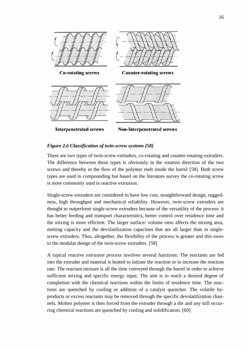
sented in Figure 2.6. [58]
16
Figure 2.6 Classification of twin-screw systems [58]
There are two types of twin-screw extruders, co-rotating and counter-rotating extruders.
The difference between these types is obviously in the rotation direction of the two
screws and thereby in the flow of the polymer melt inside the barrel [58]. Both screw
types are used in compounding but based on the literature survey the co-rotating screw
is more commonly used in reactive extrusion.
Single-screw extruders are considered to have low cost, straightforward design, rugged-
ness, high throughput and mechanical reliability. However, twin-screw extruders are
thought to outperform single-screw extruders because of the versatility of the process: it
has better feeding and transport characteristics, better control over residence time and
the mixing is more efficient. The larger surface/ volume ratio affects the mixing area,
melting capacity and the devolatilization capacities that are all larger than in single-
screw extruders. Thus, altogether, the flexibility of the process is greater and this owes
to the modular design of the twin-screw extruders. [58]
A typical reactive extrusion process involves several functions: The reactants are fed
into the extruder and material is heated to initiate the reaction or to increase the reaction
rate. The reactant mixture is all the time conveyed through the barrel in order to achieve
sufficient mixing and specific energy input. The aim is to reach a desired degree of
completion with the chemical reactions within the limits of residence time. The reac-
tions are quenched by cooling or addition of a catalyst quencher. The volatile by-
products or excess reactants may be removed through the specific devolatilization chan-
nels. Molten polymer is then forced from the extruder through a die and any still occur-
ring chemical reactions are quenched by cooling and solidification. [60]

17
For optimum operation, an extruder reactor must be custom designed with specific
knowledge of the type of chemical reaction desired. A sufficient dispersive and distribu-
tive mixing is one of the fundamental requirements for reactive extrusion process as it
ascertains the required renewal of the phase interface. However, the ultimate morpholo-
gy, that is, the size of the dispersed phase droplets, is almost independent of the rotation
speed of the screw as it affects mostly on the chemical conversion rate [61]. The flow
generated by mixing has been shown to affect the interfacial reaction rate and it has
been demonstrated that the rate constants in mixed heterogeneous systems were 1000
times higher than in static bilayer systems [62; 63]. The different screw configurations
are the solutions for this problem. Because the residence time also sets limitations to the
reaction, the length of the extruder and the screw configurations have to be selected
carefully. [49; 60]
The effects of processing conditions on the chemical conversion and morphology evolu-
tion have been studied for example by Yquel at al. [33]. A modular, intermeshing, coro-
tating twin screw extruder was used to study the evolution of the morphology of PA/PE
blends with PE bearing MA species along the extruder. In their work Yquel at al.
demonstrated, that the melting stage, in terms of both the location of its onset and its
development rate, greatly influences the chemical conversion and the morphology evo-
lution of a fast reactive compatibilization system. The study also showed that increasing
screw speed or using more restrictive screw modules at the beginning of the melting
zone promotes faster reactions and better dispersion along the extruder and thus they
have a strong effect on the distributive and dispersive mixing rates and intensity. Also,
increasing the throughput was shown to slow the evolution of the blend morphology and
decreasing the barrel temperature delays the blend compatibilization due to the slower
melting. [33]
In order for the reactive compatibilization process to result in stabilized chemical and
morphological structures the blend components have to be chosen carefully. The pres-
ence of functionalities in each phase is a must, no matter if the functional groups are
inherent or originate from in situ functionalization. The suitable functional groups are
limited by the reactivity as the reaction must take place within the residence time. [49]
2.3.2 Functionalization of polyethylene
The functionalization of polyethylenes and the synthesis of functional polyethylenes
have been studied widely. Comprehensive reviews have been written for example by
Cuang [64], Moad [57], Passaglia et al. [65] and Yanjarappa and Sivaram [66]. Polyole-
fins and especially polyethylenes have been proven to be preferred substrates for reac-
tive extrusion experiments. This may be largely attributed to their ready availability and
widespread commercial applications [57].
18
There are some molecular features that are characteristic for a reactive polymer: It con-
tains a functional group capable to react with other functional groups present in the
blend. The type, concentration and distribution of the functional group all affect the
reactivity and the reaction kinetics. [67]
In general, the synthesis of functional polyethylenes may be divided into two categories,
namely, chain end functionalization and in chain functionalization. The former method
involves functionalization of preformed terminally unsaturated polyethylenes, whereas,
the latter method involves the copolymerization of polyethylenes with comonomers
having the desired functional group. Most of the methods deploy free radical initiators
and especially the copolymerisation process is limited by the ability of many functional
groups to coordinate with the catalyst or co-catalyst components. [66]
As an option for direct synthesis of functional polyethylenes there are post-
polymerization functionalization actions. Preformed polyethylene chains may be func-
tionalized before blending process in a separate processing step by solution grafting,
melt grafting, solid state functionalization, copolymerization, end-capping, physical
procedures, surface functionalization, mechanochemical functionalization and others.
[6]
The most widespread method of introducing functionality into polyethylene substrates
in reactive extrusion process involves free radical-induced grafting onto preformed pol-
yethylene chains. The process generally involves combining a free radical initiator and a
monomer or macromonomer with the polyethylene as it is conveyed through the extrud-
er. The most commonly used initiators are peroxides although, other initiators have also
been used, such as shear induced free radicals or ionizing radiation. [57]
In general, the functional groups must be stable enough under the process conditions to
withstand high temperature and exposure to air and humidity [68]. A wide range of
monomers and macromonomers have been successfully grafted onto polyethylene sub-
strates that fulfil this requirement. Common moieties used in functionalization of poly-
ethylenes are for example maleic anhydride, MAH or MA, methacrylates, oxazoline,
vinyl silane, and maleates and fumarates. Grafting MAH onto PE is one of the most
studied reactions of polyethylene modification processes, probably due to the popularity
of MAH as a coupling agent in compatibilization reactions. Glycidyl methacrylate,
GMA is an ester of methacrylic acid and provides epoxy functionalization onto PE
chains and it has been used widely as an in situ compatibilizer in blends of polyolefins
and polyamides or polyesters. [57] Oxazoline is a more recent discovery as a reactive
functional group used in reactive extrusion. Long chain oxazolines have been reported
to be less toxic than MAH and GMA, and their boiling points are well above those of
MAH and GMA [69].

19
Burgstaller et al. [9] presented a schematic illustration of a simplified example reaction
between maleic anhydride and polyethylene when grafting MAH onto PE by radical
initiator. In Figure 2.7 the first line represents the initiation reaction for forming two
free radicals. On line two, the free radical is transferred to the polyethylene chain. The
MA grafting onto PE and the formation of a new radicalized PE chain are presented on
the last lines.
Figure 2.7 Schematic presentation of the reaction between MA and PE chain enabled
by radical grafting [9]
The radical induced grafting of functionalities onto PE and ethylene copolymers is usu-
ally accompanied with different side reactions, such as
a) radical induced crosslinking of the polyolefin substrate, which leads to the for-
mation of gels and increase in torque
b) radical induced chain scission of the polyolefin substrate,
c) shear induced degradation of the polyolefin substrate and
d) homopolymerization of the monomer. [57]
However, by the optimization of the processing parameters the extent of these side reac-
tions can be minimized [57]. In some cases the crosslinking may be even totally avoid-
ed and a completely soluble product is provided and still very high grafting yields can
be obtained [9].
There are many factors in reactive processing affecting the grafting yield, that is, the
fraction of the monomer that is grafted onto the polymer versus that which is either un-
20
changed or is consumed in side reactions such as homopolymerization. The processing
related factors include such as mixing efficiency, temperature, pressure, residence time,
venting or the design of the screw or the extruder. Also the blend composition related
factors, such as the selection and concentration of the base polymer, monomers, initiator
and co-agents. [57]
Chuai et al. [70] reported on the increasing grafting degree with increasing free MAH
concentration as they studied the melt grafting of maleic anhydride onto LDPE. Their
results showed a systematical increase up to 5.1% of grafting with MAH content of 0.14
wt.% and above that the grafting degree showed a linear decrease. Chuai et al. suggest-
ed that the chemical reactions for the grafting almost terminate at 0.14 wt.% if the ther-
mal degradation is neglected. In the same study it was also shown that the peroxide ini-
tiator concentration up to 0.45 wt.% results with increasing grafting degree and beyond
that the degree starts to drop. They suggested, that this phenomenon directly demon-
strates that when high concentration of the initiator is added to the reaction mixture, the
rate of generation of free radical species reaches such a high value that the homopoly-
merization of MAH becomes more significant and thus depressing the grafting process.
Also the grafting temperature was shown to have an effect on grafting degree and the
highest degree resulted at 160°C.
In reactive extrusion the monomer can be added simultaneously with the polyolefin or it
can be added to the molten polyolefin directly, adsorbed on further polymer, or be dis-
solved in an appropriate solvent. The best method depends on the solubility of the mon-
omer in the polyolefin melt and the stability and volatility of the monomer. Initiators
used in the process have to be selected carefully for the grafting experiment. Most
commonly initiators are dialkyl peroxides but also other initiators are used. The method
of introducing the initiator also affects the selection and the extent of side reaction and
the formation of initiator derived by-products. The susceptibility of the initiator to in-
duced decomposition and other side reaction is to be taken into account. [57]
As the architecture of the reactive polymer affects its ability to act sufficiently as a
compatibilizer, at least three aspects of the structure of the maleated polyethylene need
to be considered:
a) The nature of the anhydride functionality that is the possibility of oligo-MAH
grafts or adjacent grafts.
b) The distribution of the anhydride functionality along the polyolefin chain and
between chains (typically 0.5-2 wt.%, which basically means only about one or
two units per chain).
c) The relationship between the nature, distribution and level of grafted functionali-
ty, and other aspects of polyolefin structure (e.g. molecular weight, polydispersi-
ty, density or degree of branching). [57]

21
In studies by Heinen et al. [71] it was shown that the MAH may be attached to polyeth-
ylene backbone at methine sites (Figure 2.8a) or at methylene sites (Figure 2.8b and c).
Figure 2.8 Scheme of possible sites for MAH to be attached at a) methine site, b) and
c) methylene sites. [57]
Their work suggests that grafted MAH appears dominantly as oligo(MAH) blocks in
HDPE (Figure 2.8c) with chain length of the oligo (MAH) averaging between one and
two units, and in LLDPE both oligo(MAH) at methylene sites and succinic anhydride
units at methine sites. The same results were obtained by Ranganathan et al. [72] who
also reported that the distribution of the MAH-residues at tertiary methine sites was
random.
2.3.3 Compatibilization reactions
The compatibilization reaction, that is, the in situ formation of copolymers between the
blend components is an essential step in reactive compatibilization process. When poly-
olefins, and in this case polyethylene especially, are considered, these inter-chain poly-
mer reactions can be divided into three categories based on the type of the structure of
the component reacting with modified, namely, the reactive polyethylene.
The first class is end-functional polymers with reactive polyethylene. Normally the
product of this reaction is the formation of a graft copolymer. A major limitation for this
compatibilization reaction is the commercial availability of end-functional polymers.
Most of these are condensation polymers which by their nature have potentially reactive
end-groups, such as, polyamides with amino and/or carboxy end groups, polyesters and
polycarbonates with hydroxyl and carboxy end groups and polyethers commonly with
hydroxyl end groups. However, the end group functionality also depends on the pro-
cessing history and with commercial products the available functionalities are not nec-
essarily specified. [57]
Polyfunctional polymers with multiple side chains reacting with modified polyethylenes
are the second class. These reactions have been used to synthesize graft copolymers, but
due to the polyfunctionality of both substrates, also cross-linked products can be gener-
ated. The cross-linking can be avoided by careful selection of substrates and control of
processing conditions. For example, copolymer of vinyl and styrene with oxazoline
moieties have been used in blends with modified polyolefins. [57]

22
In the last class are the reactions between polyethylene and another polymer by using a
coupling agent. The coupling agent forms linkages between the polymer chains and an
in situ synthesis of a graft copolymer may occur. The reactions usually require peroxide
initiator and possibly a polyfunctional monomer as a coupling agent. [57]
The variation of the formed compatibilizer structure is also represented in Figure 2.9.
Compatibilizer with end reactive functional groups can form block copolymers with
another blend component containing also end reactive groups (Alternative I) and graft
copolymers with a blend component with inherent pendant groups (Alternative II). An
addition of reactive polymer carrying pendant reactive groups may generate grafted
copolymers (Alternative III) or branched copolymers (Alternative IV). [51]
The three important things to be taken into account when considering the controlling of
the copolymer formation at the interfaces are the chemistry of the blend components,
the kinetics of the reactions and the architecture of the forming copolymer. The chemis-
try of the blend includes the chemicals involved in the compatibilization reactions and
the new bonds formed between the components. All the components should sustain the
processing environments and meet the health and safety regulations. [61] The functional
groups in the components determine the possible reactions, and in order for successful
compatibilization reactions to occur the reaction should be fast, selective and preferably
irreversible. Functional groups with a capability to take part in these type of reactions,
and react with the functionalised compatibilizer precursors, are such as maleic anhy-
dride, carboxylic acid, primary and secondary amines, hydroxyl groups, heterocyclic
groups and groups with interchange reaction or ionic interaction capabilities. [50]
Figure 2.10 represents some examples of functional groups taking part in compatibiliza-
tion reactions and possible chemical bonds that may form. The reactions are classified
by the functionality of the compatibilizer precursor (X, left hand side column) and pos-
sible functional groups that are able to react with the CP (Y, mid-column). The right
hand side column in Figure 2.10 represent the bonds forming between the functionali-
ties X and Y, X’-Y’.
Most of the compatibilization reactions are condensation reaction between a nucleo-
philic end group (that is, electron donor, for example -NH2, -COOH, and -OH) and an
electrophilic group (for example cyclic anhydride, epoxy, and isocyanate). The resulting
reaction is usually a formation of new chemical groups, such as imide group in the reac-
tion of cyclic anhydride and amine, or ring opening reactions such as in reaction be-
tween epoxy and carboxylic acid or oxazoline and alcohol. [6]

23
Figure 2.9 Types of copolymers formed during reactive processing [51]
Reaction kinetics, that is, the rate of inter-chain copolymer formation is affected by the
inherent reactivity of the components and the functional groups involved. The kinetics
depends on the interfacial area available and thus sufficient mixing is of importance. By
selecting a suitable functional group pair with sufficient reactivity the conversion rates
are possible to keep within the required limits of reactive processing. However, the de-
termination of the reactivity can be difficult. [61; 63]

24
Figure 2.10 Reactive groups involved in reactive processing [51]

25
The reactivity of specific functional group pairs were studied by Orr et al. [73]. They
measured homogenous coupling kinetics of terminally functional polymers by attaching
a variety of functional groups to the end of polystyrene, PS and polymethyl methacry-
late, PMMA. In order of increasing reactivity, functional group pairs are: acid/amine,
hydroxyl/(anhydride or acid), aromatic amine/epoxy, aliphatic amine/epoxy, ac-
id/oxazoline, acid/epoxy, aromatic amine/anhydride, and aliphatic amine/anhydride.
[73]
One factor affecting the reactivity and reaction kinetics is the architecture of the reac-
tion components, namely, the compatibilizing efficiency is closely related to the loca-
tion and amount of reactive groups. However, the architecture is often unknown or dif-
ficult to control. [61] The reaction rate constants for different end-functional and mid-
functional chains were studied by Jeon et al. [62]. They compared the reactivity for an
end-functional chain reacting with and an end-functional chain versus reacting with a
mid-functional chain by using competitive reactions of end- and mid-functional phthalic
anhydrides with amine groups. It was found that the mid-functional reaction was slower
to react under all reaction conditions investigated. [62]
2.4 Characterization of compatibilized blends
There are different aspects to characterize in compatibilized polymer blends: some of
them focus more on the effect of compatibilization on the end properties of the material
and not on the actual chemical products resulting in reactive blending. These types of
characterization methods are morphological and mechanical methods. The structural
characterization focuses on providing information of the actual chemical structures ob-
tained in the blend. By combining these methods a wide range of information may be
gathered, for example on the compatibilization efficiency, homogeneity of the blend and
the effects of blend composition. The methods based on the end-property characteriza-
tion are thought to be simpler as the concentrations of functional groups and thus the
concentration of formed compatibilizer are rather low and thus the sensitivity of struc-
tural characterization methods has to be sufficiently high. This section covers the most
common characterization methods by dividing them into morphological, mechanical,
structural and other characterization methods.
2.4.1 Morphological characterization
The aim for the morphological characterization is to define the phase structure, that is,
for example the size and distribution of the dispersed phase droplets and the texture and
homogeneity of the polymer blend in general. Morphological characterization can also
study the character of interfacial layer and identify the existence of micelles, or
mesophases. [5]

26
One of the most often used method for morphological characterization is to use scan-
ning electron microscopy, SEM. It gives visual images of the material surface based on
the behaviour of the electron beam as it hits the surface. From the produced images the
particle size and shape of the dispersed phase, for example, can be determined. Also the
evolution of the structure based on processing conditions can be studied by using SEM.
Transmission electron microscopy, TEM, is more time-consuming method, but in addi-
tion to the morphology description similar to SEM, TEM provides a wider scale of pos-
sibilities, such as localisation of a block copolymer used as a compatibilizer in blends of
immiscible polymers. [5]
Figure 2.11 presents an example of the differences in SEM micrographs obtained at the
surfaces of fractured samples of PE/PA blends with and without compatibilizer. Figure
2.11a represents a blend with composition of PE/PA 80/20 and Figure 2.11b represents
a blend of PE/PA/PE-g-OXA 75/15/10, where PE-g-OXA is the oxazoline grafted poly-
ethylene acting as a compatibilizing precursor in the blend. It can be seen in the figures
how the particle size degreases significantly after the addition of compatibilizer and the
structure is altogether more uniform. [28]
Figure 2.11 SEM micrographs of fracture surfaces of a) uncompatibilized and b) PE-
g-OXA compatibilized samples [28]
Light scattering methods can study larger blend volume than electron microscopy meth-
ods and it has been used to detect phase transitions in polymer blends and in determina-
tion of droplet size, not only in the solid but also in the molten stage. [5]
Also other methods can be deployed when determining the morphology of polymer
blends. Wide-angle X-ray scattering, WAXS or small-angle scattering, SAXS methods
can be used to study the crystallisation in blends of semicrystalline polymers [5]. Ultra-
sonics have also been used to characterise morphology and it has been even used in sit-
uations where rapid, in situ characterization for melt blends has been needed [29].
Differential scanning calorimetry, DSC, can be used for discrimination between misci-
ble and immiscible blends. As the technique measures the changes in enthalpy of the
studied material under a certain temperature-time program it is possible to couple the

27
thermal behaviour with diverse physical and chemical events. DSC technique enables
the evaluation of heat absorbed or emitted and thus information on, for example, glass
transition, melting and crystallisation can be obtained. [74] The presence of only one
glass transition temperatures, Tg, is an indication of a miscible blend and two Tgs indi-
cate an immiscible blend [50]. For partially miscible systems two Tgs shifted to the di-
rection of their average can be obtained [5].
2.4.2 Characterization of mechanical properties
In many cases, mechanical properties can be used as an indicator of the compatibiliza-
tion efficiency as the formation of inter-chain copolymers generates a stress transfer
mechanism between the two immiscible phases and enhances the interfacial adhesion.
Properties, such as tensile strength, impact strength and tensile modulus have been used
to screen the changes in the stress transfer abilities and thus, the compatibilization effi-
ciency. [5]
Hamid et. al. [15] reported on the studies on the mechanical properties of PA6/HDPE-g-
MAH/HDPE blends. They studied a series combination of PA6/HDPE (70/30) blends
with varying amount of compatibilizer. Their studies showed an increase in many me-
chanical properties, such as tensile modulus, tensile strength, flexural modulus and
hardness when incorporating up to 2 wt.% of compatibilizer into the blend structure.
This amount was enough to increase the interfacial adhesion between the blend compo-
nents as the HDPE-g-PA6 copolymer was formed during reactive blending. With excess
amount of compatibilizer (over 2wt.%) these properties started to gradually decrease.
2.4.3 Structural characterization
Structural characterization gives more detailed information about the chemical structure
of the blend, that is, the structure of the blend components, and about the bonds formed
during reactive processing.
The simplest aim for the structural characterization is to provide some evidence on
graft-copolymer formation. For blends of PE and PA this type of characterization meth-
od is the Molau test [75]. It is a qualitative method for assessing the compatibilization
efficiency as it detects the formation of PE-g-PA compatibilizer. The test can be used to
prove, that the reaction between polyamide and compatibilizer precursor, such as
HDPE-g-MA, actually happens. The method is related to fractionated dissolution as the
compatibilized blend sample is diluted in formic acid and the graft or block copolymer
formed during blending can then act as an surfactant and stabilize the colloidal suspen-
sion of polyolefin particles into the formic acid suspension. The formation of a stable
suspension can be taken as an indication of the presence of PE-g-PA copolymer. [16;
27; 75]

28
Another method to indicate the presence of the compatibilizing graft copolymers is Fou-
rier transform infrared, FTIR spectrometry. FTIR, or more commonly known as infra-
red, IR spectroscopy can be used to identify polymeric materials as the method is able
to identify all the characteristic molecular rotations and vibrations induced by the elec-
tromagnetic radiation in IR region. As a result the IR absorption pattern for every mate-
rial is unique and it correlates to the molecular structure of the material, and therefore,
the formed bonds and functionalities can identified. [74]
In addition to the determination of miscibility of polymer blend, DSC traces can also be
used in characterization of the interactions between the blend phases and, thus, to get
some information on the structure. An example of changes in DSC traces depending on
the type and amount of the compatibilizer and the structures in the blend, reported by
Anttila et al. [76], is represented in Figure 2.12. In the melting thermographs of uncom-
patibilized (B 0) and compatibilized (B 10-15) PE/PA blends it can be seen how the
melting peaks of PA (around 220 °C) and PE (around 115 °C) shift towards each other
as compatibilizer is added in the blend. Also the melting peak representing PE becomes
wider. The widening is suggested to be due to the different crystallisation temperature
of PE phase and the compatibilizer. [76]
Figure 2.12 DSC melting curves of uncompatibilized and compatibilized PA/PE
blends. [76]
DSC can also be deployed in obtaining fractionated crystallisation in immiscible poly-
mer blends and the evolution of this phenomenon can be used as an indicator of the
compatibilization efficiency. The fractionated crystallisation is based on the different
type of crystallization processes (homogeneous, heterogeneous and self-nucleation) in
polymer melts, as the bulk polymer is subdivided into isolated regions, such as droplets
29
of the minor phase dispersed into immiscible polymer matrix. The crystallization upon
cooling from the melt can occur in several temperature intervals that are initiated at dif-
ferent undercooling due to the finer particle size of the droplets. In these cases the crys-
tallization may end up occurring at the homogeneous crystallization temperature, Tc,hom.
Compatibilization of immiscible blends has been observed to affect the crystallization
behaviour mainly by affecting the size and number of the dispersed phase droplets but it
has also been suggested that it is partially due to the isolating core-shell structure that
the compatibilizer forms around the droplets preventing the direct nucleating effect
from one phase to another. It has also been shown that fractionated crystallization is
related to the lack of active nuclei in the dispersed droplets by means of self-seeding
experiments by Sánches et al. [77]. The evolution of the delayed crystallization peaks,
that is, the shifting of the peaks towards lower temperatures, in DSC scans of compati-
bilized immiscible polymer blend can thus be used in qualitative evaluation of the com-
patibilization efficiency of the studied polymer blend. The stronger the shift of the peak
is the higher compatibilization efficiency the blend has. [32; 78; 79]
Pang et al. [80] were able to link the glass transition process and the degree of compati-
bilization. They studied the thermal properties of PE/PA blends and found that the heat
capacity increment at the glass transition (∆Cp) is a sensitive and important parameter
for quantitative characterization of the degree of compatibilization. This is because the
change of ∆Cp is actually a measure of interfacial content. Thus, the magnitude of ∆Cp
value provides a quantitative measure of the degree of compatibilization.
2.4.4 Other characterization methods
The rheology of a polymer blend is an important factor when concerning the process
ability of the material. The melt state behaviour has also been shown to relate to other
blend properties and morphology and therefore, rheological characterization is also an
informative characterization method.
Kudva et. al. [19] studied the rheological properties of a binary blend of PA6/PE-g-MA
by using torque rheometer. Torque rheometers are usually a part of a normal mixer or
extruder and it is essentially an instrument that measures viscosity-related torque caused
by the resistance of the material to the shearing action of the plasticating process [81].
The Brabender torque of blends of PA with various maleated polyethylenes were meas-
ured and their results are shown in Figure 2.13.

30
Figure 2.13 Effect of blend composition and the type of compatibilizer precursor on
the rheological properties. [19]
As presented in the graph, each of the blends has a higher Brabender torque than either
of the blend components which is evidence that grafting reactions occurred. Higher
MA-content leads to a higher torque and with same MA content the PE with higher vis-
cosity reveals a substantially higher torque. A somewhat larger torque was expected
based on the physical consideration of mixture additivity of viscosity, but in addition it
was also speculated that the extent of grafting is greater when two pure phases become
nearly matched in melt viscosity since this will tend, just on physical grounds, to lead to
a finer dispersion or more surface area where grafting can occur. [19]
Melt flow rate (MFR) can be used to measure the melt flow of a polymer melt trough a
die at a certain temperature under a certain weight [74]. The test is normally used in
quality control and it is an indirect measure of molecular weight and it is inversely pro-
portional to the viscosity of the melt under similar conditions. Low MFR is an indica-
tion of high molecular weight and vice versa.
Other methods deployed in characterization of polymer blends are for example Dynam-
ic Mechanical Analysis, DMA [14], Thermogravimetric methods (TGA) [27] and three
point bending test of shape memory experiments [21].

31
3. BLENDS OF POLYETHYLENE AND POLYAM-
IDE
Polyethylene and polyamide form an immiscible blend due to the differences in the po-
larity. The blend has been under extensive studies during the past two decades due to
the versatility of the properties of the blend when compatibilized properly. Polyethylene
offers sealability, processability, flexibility, impact strength and moisture insensitivity,
whereas polyamide offers strength, thermal stability and barrier properties. By blending
new property combinations may be reached. [6; 16]
This chapter is a case study of the blends of polyethylene and polyamide. The first sec-
tions cover the basics of polyethylenes and polyamides, and the next sections of the
chapter focuses on different blend components and compatibilization methods used in
PE/PA blends. The last section covers more thoroughly the use of maleic anhydride as
the coupling agent in these blends and the effect of the blend composition on the proper-
ties of the final blend.
3.1 Polyethylene
In general polyethylenes are semi-crystalline thermoplastic polymers with a range of
mechanical properties depending on the material density, and for example the high den-
sity PE is the most rigid and the low-density PE more flexible. It has good moisture
resistance and it chemically inert with a range of substances. [82; 83]
Low-density polyethylene, LDPE was the first thermoplastic polyolefin used commer-
cially. It is also known as “high pressure” polyethylene because it is exclusively made
by high pressure process. The structure of LDPE is branched, as represented in Figure
3.1 due to the free radical polymerization. The branching of LDPE gives it a unique
rheological behaviour and properties and it is used widely in film, coating, wire and
cable, and moulding applications. The properties of LDPE are dependent on the struc-
ture of the polymer chains, i.e. the molecular weight, molecular weight distribution,
MWD, frequency of short-chain branches, and frequency and length of the long chain
branches. [83]

32
Figure 3.1 Structural differences between high-pressure LDPE and conventional
LLDPE. Adapted from: [84]
High density polyethylene, HDPE, is a predominantly a linear polymer with some short
chain branching. As the name says, the density of HDPE is high, ranging from 0.941 to
0.961 g/cm3 or even over that. HDPE is polymerized by low-pressure process using
catalysts, such as the Phillips chromium catalyst, Ziegler-Natta catalyst or metallocene
catalyst. [59, 82]
The structure of linear low-density-polyethylene, LLDPE resemble more of HDPE as it
lacks the long-chain branching of LDPE. Also the molecular weight distribution of
LLDPE is narrower than that of LDPE. The polymerization process is similar to the
low-pressure processes of HDPE and the density of LLDPE is strongly controlled by
comonomer (such as hexene, butene or octene) content and distribution. Most of the
branching due to comonomer is randomly distributed along the polymer backbone. [84]
It has been stated that the properties of polyethylenes depend on the structure of poly-
mer chain, especially on molecular weight and molecular weight distribution. Generally,
the high MW results usually in better mechanical properties of the final product, but the
high MW will also bring rise to high melt viscosity and poor processability. On the oth-
er hand, with low-molecular weight the properties go vice versa. This conflict between
processability and mechanical properties has been recently resolved by using polyeth-
ylene with bimodal molecular weight distribution, defined as bimodal PE. [85]
The bimodal PE is composed of low molecular weight PE fraction responsible for stiff-
ness and creep resistance in crystalline phase and the lower melt viscosity during pro-
cessing, and of high-molecular weight fraction, which acts as the tie molecule connect-
ing the crystalline lamellae and therefore improves the impact strength and stress crack-
ing resistance. [85]
3.2 Polyamide
Polyamides are a family of materials containing different monomers combined by am-
ide (–NH-CO-) bonds. The type of polyamine depends on the monomers employed.

33
Polyamides are also called as ‘nylons’ in the terminology when referring to aliphatic
and semi-aromatic polyamides, and ‘aramides’ when referring to aromatic polyamides.
[86]
The most important polyamides are nylon 6 and nylon 66 (Figure 3.2) accounting for
more than 90% of polyamide usage. The number in the type of polyamide corresponds
to the number of carbon atoms in the monomers, that is, the nylon 6 consists of one
monomer, lactam, that includes both amine (-NH2) and acid (-COOH) functionalities
and nylon 66 consists of dicarboxylic acid and diamine monomers. [86; 87]
Figure 3.2 Polyamide 6 and polyamide 66 structures [88]
Polyamides are engineering thermoplastics with a combination of mechanical and ther-
mal properties that allow them to be employed for highly specified end uses. Polyam-
ides are used in fibrous form to reinforce composite structures and as main material for
example in textiles and automotive applications. In packaging applications polyamides
are used for example in multilayer film to bring mechanical strength and barrier proper-
ties. [87]
3.3 Compatibilization of PE/PA blends
The most common methods to compatibilize PE/PA blends are the addition of reactive
polymer, the in situ functionalization and addition of low-molecular weight reagents. As
noted before, there are several functional groups capable to react with the amide and
acid functionalities of polyamide. Not only polyethylene is used as the backbone for the
reactive polymer but also other polymers miscible with polyethylene are used, such as
styrene ethylene butylene styrene copolymer, SEBS; or ethylene propylene diene rub-
ber, EPDM.
The blend of polyethylene and polyamide has many potential compositions as there are
different types of polyethylenes and polyamides from which to choose. Burgstaller et al.
[9] studied the influence of polyethylene type, that is, HDPE, LDPE and LLDPE, on the
properties and morphology in PE/PA blends. They had two approaches to generate the
compatibilizer in situ: the use of prefabricated PE-g-MA compatibilizer precursor and

34
forming the compatibilizer in situ by grafting the MAH molecules onto the PE chain
and forming PE-g-PA graft copolymer compatibilizer in a single step. They compared
the mechanical, rheological and morphological properties of three different PE/PA
blends containing HDPE, LDPE and LLDPE, respectively. All the blends with different
types of PE showed significant effects on the properties and morphology when compat-
ibilized, such as reduction in domain size of the dispersed phase and increased impact
strength. The differences between the polyethylene types were only minor and it was
suggested that these small differences were due to the different viscosities and the re-
sulting shear forces in the blends. [9]
In studied of Kudva et al. [19] the effect of melt viscosity on the properties was studied.
As blends of high viscosity PA6 and different maleated polyethylenes were studied the
low viscosity maleated polyethylene was found to be ineffective for toughening two
nylon 6 materials with different MW and different viscosities. This was suggested to
result from the large mismatch in the melt viscosity of the blend components because
the low viscosity PE phase tended to become continuous even when it was the minority
component. The blend was suggested to be near the phase inversion point which is for
non-reactive systems given by the following equation:
𝜂1𝜙2
𝜂2𝜙1= 1,
(2)
where the ηi is the melt viscosity of the phase i and ϕi is the volume fraction of the
phase i. The differing viscosities were also found to affect the grafting yield as the larg-
er mismatch between the blend components resulted in lower torques during blending
and thus, less formation of PE-g-PA compatibilizer, than with the blend with viscosities
closer to each other. The toughening abilities of the high viscosity polyethylenes, both,
with 0.3 and 0.9 wt.% of anhydride contents were found to be significantly better for
high viscosity PA.
Most studies on PE/PA focus on blending PA6 of all the polyamide types. This is most
probably due to the simplicity of the structure and the general usage in the industry for
extrusion and injection moulding, whereas nylon 66 is more used in fibrous applica-
tions. [89]
The selection of a suitable compatibilizer precursor is one of the most critical factors in
compatibilization process and the selection from which to choose is wide. The most
frequently used are MA-functionalised polyethylenes [4; 7; 9; 11; 15-18; 21] and eth-
ylene glycydyl methacrylate copolymer, EGMA [10; 22; 30; 32]. Other polyethylene
based reactive polymers are, for example, ethylene oxide (PEO) [14], ethylene acrylic
acid, EAA [22; 32; 34; 90], silane grafted polyethylene, HDPE-g-Si [25], isocyanate
grafted polyethylene, HDPE-g-HI [23], oxazoline grafted PE [28; 91], and polyethylene
functionalized by using metallocene catalysts, NHMe, and resulting in functional

35
groups of -OH, COOH, [76]. The utilization of a third component in the blend is also a
common method, as long as the third component is miscible or at least partially miscible
with one of the two main phases, usually with polyethylene. Examples of these type of
compatibilizer precursors are such as MA or GMA grafted styrene ethylene butylene
styrene, SEBS [11; 12], MA-grafted styrene ethylene propylene copolymer, SEP-g-MA
[11], ethylene vinyl acetate, EVA, and ethylene butyl acrylate copolymer EBA, both
with MA functionalities [8], and maleated ethylene-propylene diene rubber EPDM-g-
MA [20; 26].
A different approach for compatibilization of blends of polyethylene and polyamide was
taken by Araújo et al. [4] and Vallim et al. [27] who used recycled, post-consumer
HDPE, rHDPE, as a compatibilizer. The rHDPE possesses polar groups formed by oxi-
dative degradation during its use and disposal and these polar groups are able to form
chemical bonds between PE and the amine groups of PA. It was shown, that the rHDPE
improved the mechanical properties of the blends more than the use of PE-g-MA as a
compatibilizer precursor. Also the domain size of the dispersed phase droplets was re-
duced in the same magnitude as when using PE-g-MA.
The use of recycled blend components does not limit only to compatibilizer, but recy-
cled polyethylenes and polyamides have been studied by several researchers. Recycled
polyethylenes and polyamides have been studied when blended with other polymers
[92; 93] and with each other [4; 27; 94]. Blends of post-production LDPE with a small
amount of polyethylene methacrylic acid, EMAA, and post-consumer PA 66 were stud-
ied by Desiderá and Felisberti [94].
Also multilayer polymer waste containing among others PE and PA has been an interest
of study. Hong et al. [95] studied blends of polypropylene and post-consumer nylon
waste (containing also LDPE and LLDPE) and the addition of compatibilizers was
shown to improve the mechanical and rheological properties, reduce the domain size
and refine the coarsening of the morphology. In the studies of Choudhury et al. [96] a
post-consumer waste oil pouch made of co-extruded multilayer film was under inspec-
tions. Pouches were reported to contain about 83 wt.% of LDPE/LLDPE mixture, 15
wt.% of PA and 2 wt.% of additives. The use of compatibilizer was found to improve
remarkably the interfacial adhesion between PE and PA phases and therefore also the
mechanical properties and thermal stability.
The comparison between the reactive polymers is not straight forward but some studies
have also been reported on that matter. Many studies focus on comparing different
compatibilizers to each other e.g. in the field of compatibilization effectiveness or reac-
tivity. The research group of Filippi et al. [10-12; 16; 34] studied the effect of compati-
bilizer precursors on morphology and mechanical properties of PE/PA blends. They
discussed about the effectiveness of different type of compatibilizers, i.e. ethylene acryl-
ic acid copolymers, EAA, [34; 90], maleic anhydride grafted polyethylenes, PE-g-MA

36
[16], ethylene glycidyl methacrylate copolymers, EGMA [10], styrene eth-
ylene/butylene styrene copolymers, SEBS grafted with MA and GMA [12] and MA-
grafted styrene ethylene/propylene copolymer SEP-g-MA [11]. The results of their stud-
ies confirmed that the compatibilizers with MA-functionality are more effective com-
patibilizers for LDPE/PA blends, than that of the ethylene-acrylic acid and ethylene-
glycidyl methacrylate copolymers. The efficiency of different MA grafted compatibil-
izer precursors was shown to depend on the structure and molar mass of the back bone
chain. The effect of the type of polyethylene is discussed further in the section 3.4.2 but
in general the PE-g-MA showed a slightly lower activity than SEP-g-MA or SEBS-g-
MA towards 75/25 LDPE/PA blends. However, all the studied maleated CP’s demon-
strated to be effective when used to compatibilize blends of polyethylene and polyamide
[11].
The type of compatibilizer has been shown to affect the crystallization behaviour of
compatibilized immiscible polymer blends. The effectiveness of three different compat-
ibilizers studied by Filippi et al. [10-12; 16; 34] was rated qualitatively by Yordanov
and Minkova [32] who studied fractionated crystallization phenomenon and polydisper-
sity of the dispersed PA phase in compatibilized 75/25 PE/PA blends. They observed
clear fractionation in the crystallization with two of the studied compatibilizer precur-
sors and by the extent of the fractionated crystallization they were able to suggest a
qualitative evaluation of the degree of compatibilization. The studied CPs were rated
according to their reactivity as follows: SEBS-g-MA > EAA > EGMA.
3.4 Maleic anhydride as coupling agent in PE/PA blends
Using maleic anhydride grafted polyethylene as the compatibilizing precursor seems to
be the most deployed method when compatibilizing the blends of PE and PA. This sec-
tion focuses on blends in which MAH acts as a coupling agent, mostly while grafted on
PE chain. The first sub-section covers the compatibilization reaction between PA and
MAH, and the factors affecting this reaction. The second sub-section focuses on the
effects of the blend composition variation in PE/PA/CP blends on the properties of the
final material.
3.4.1 Compatibilization reaction between PA and MAH
Polyamide usually contains the reactive groups of amine and/or carbocylic acid. Poly-
amide 6 and polyamide 66 most often contain both of the functionalities due to the ring
opening polymerisation of PA 6 or by polycondensation of PA 66. Therefore, the reac-
tive polymer has 3 different potential functionalities to react with: amine (-NH2) and
acid (-COOH) end groups and in-chain amide (-NH-CO-) groups. It has been shown
that the compatibilization reaction between PA and MAH results in generation of amide
or imide linkage. [97]

37
The amide and imide linkages may form in two ways between MAH and PA: the anhy-
dride group reacting either with the amine end group of PA or with the in-chain amide
groups. These two reactions are illustrated in Figure 3.3. The reaction between MAH
and amine end-groups is a condensation reaction consisting of two steps: the reaction of
anhydride group with one amide forms an amic acid function, which then transforms
into an imide cycle generating one water molecule. The formation of water molecule
may lead at certain processing conditions to hydrolysis of PA and, thus, the two reac-
tions may lead to same reaction products. The hydrolysis may be prevented by proper
ventilation of the extruder. [7; 16]
Figure 3.3 Schematic presentation of maleated polyethylene reacting with a) the end
b) the in-chain groups of PA [16]
Maréchal et al. [98] compared the reactivity and reaction kinetics of amine end groups
and in-chain amide groups when reacting with succinic anhydride group. Their studies
showed that the mechanism in which the anhydride reacts with the amine chain end
group is dominant in the early stages when the starting amine concentration is high.
Even though the amide concentration in polyamide is much higher than the amine con-
centrations, the amine-anhydride reaction is much faster and, thus, when the anhydride
concentration is lower than the amine concentrations, the amide-anhydride reaction is
negligible. The concentration of the amine chain ends will increase via hydrolysis usual-

38
ly only in the case when there are more anhydride groups than amine groups as the reac-
tion kinetics of the hydrolysis is quick enough. [98]
The conversion rate of the reaction between amine and anhydride groups is affected by
many factors, such as processing condition, the structure of the CP and the blend com-
position. The reaction kinetics was found to be affected by the monomer structure on
amine-anhydride reactions at polymer/polymer interfaces. Jones et al. [99] studied the
variation in thermodynamic interaction parameter χ by changing the chemical structure
of the backbone. It was shown that both increased χ and molecular weight decrease the
conversion rate and degree.
The conversion ratio was studied by Argoud et al. [7] by mixing 60 vol. % of PA 6 with
a mixture of HDPE and HDPE-g-MA in which the fraction of the CP decreased from 40
vol.% to 0. The conversion degree was obtained from the absorption band of anhydride
carbonyl in the IR spectra which indicated the unreacted anhydride moieties. The ob-
tained conversion rates were plotted as a function of the initial molar ratio of MA
groups on amine end-groups and these results are presented with black diamond sym-
bols in Figure 3.4. The maximum theoretical conversion rate is also presented with con-
tinuous line in the same graph.
Figure 3.4 Maximum theoretical (continuous line) and experimental (diamond sym-
bols) conversion rates versus the initial molar ratio [MA]/[NH2] studied by Argoud et
al. [7]

39
Argound et al. presented an example of a blend with composition of PA/PE/CP
50/30/20 vol.% with a ratio [MA]/[NH2]≈1, for an estimated conversion ratio of about
80%, as in Figure 3.4, 80% of PA chains are grafted to PE-g-MA, while 32 vol.% of PE
phase (80% of the 40 vol.% of the compatibilizer precursor on PE phase) is constituted
of the PE blocks of the graft copolymer. The result is that the graft copolymer is the
majority component in the material. [7]
3.4.2 Effects of the blend composition
It has been many times already demonstrated how the variations in the blend composi-
tion of PE/PA/CP blends have an effect on the morphology and the final properties of
the blend. The estimation of these effects is not always simple as the blend has 3 com-
ponents and the changes in the concentration of one component changes the relative
proportions of the other component also, and thus, tertiary blends are complex systems.
No simple binary graphs can be drawn, unless one, or even two, of the components are
kept constant.
The ratio of polyethylene and polyamide is a rather dominant factor affecting the prop-
erties of compatibilized PE/PA blends. In studies by Araújo et al. [4] the maximum
yield stress of injection moulded test specimens with different blend compositions were
compared. They studied the uncompatibilized and compatibilized (by 2 wt.% of PE-g-
MA) HDPE and recycled post-consumer polyethylene, PEpc in blends with PA6 over
the whole range of composition from 0 to 100 wt.% of PA6. As shown in Figure 3.5 the
trend set by the uncompatibilized blend is repeated by the compatibilized and recycled
blends, though, the results of the compatibilized blends are significantly higher values
than those of the uncompatibilized blend. The trend is set by the continuous matrix
phase.

40
Figure 3.5 Variation of the maximum yielding stress, σmax, as a function of composi-
tion for PE/PA blend with different compatibilizers. [4]
The morphologies of tertiary HDPE/PA6/CP blends over a wide range of compositions
prepared by reactive extrusion were studied by Argoud et al. [7]. They focused espe-
cially on high concentrations of the compatibilizer precursor and used SEM images to
analyse the morphology with varying compositions. They observed 5 different mor-
phologies: 1) PA droplets dispersed in a PE phase matrix; 2) PA stretched dispersion in
a PE phase matrix; 3) co-continuous (the situation in which both phases form single co-
continuous domains, without isolated drops); 4) PE phase stretched dispersion in a PA
matrix; 5) PE phase droplets dispersed in a PA matrix. [7]
There are two ways to alter the MA content in a blend: by varying the grafting degree or
the reactive polymer or by altering the concentration of the reactive polymer. Same total
concentrations of MA moieties can be obtained by both methods, but as denoted earlier,
the structural characters, such as grafting degree, can affect the reactivity of the compat-
ibilizer precursor, and therefore the effect of grafting degree and concentration of com-
patibilizer precursors are elaborated here separately.
Commercially the content of MA grafted on the polyethylene is usually between 0.5 and
2 wt.% [57]. The effect of grafting degree was studied by Jiang et al. [16]. They com-
pared the evolution of particle size and torque at the end of mixing as a function of MA
grafting level in the compatibilizer precursor when keeping the PE/PA/CP ratio as con-
stant. Their studies supported the findings of Kudva et al. [19], who reported of increas-
ing torque as the MA content increased from 0.3 to 0.9 wt.%, as reported in the context
of characterizing the melt viscosity properties of polymer blends in section 2.4.4. The
results of Jiang et al. indicated that a strong enhancement of dispersion of PA droplets is
found by using a CP with only 0.3 wt.% of MA, and that no further improvement is
obtained by increasing grafting degree beyond 0.8 wt.%. This effect was paralleled by

41
an increase of melt viscosity, indicated by the final torque at the end of mixing which
also sets on a plateau after 0.8 wt.% of MA. [16]
Chuai et al. [70] reported on an apparent increase in tensile strength with increasing
grafting degree of MAH onto PE chains. The grafting degree was determined by using
FTIR characterization. The authors studied 70/30 LDPE-g-MA/PA6 blends and accord-
ing to their results the tensile strength increases up to 5.1% of grafting degree and above
that it starts to decrease. This observation is also supported by Kudva et al. [19] who
reported on increase in the mechanical properties by increasing MA grafting degree.
The effect of the amount of compatibilizer precursor was studied by Jiang et al. [16].
While altering the amount of CP the ratio of polyethylene and polyamide was kept con-
stant. They evaluated the effect on the particle size distribution of the dispersed phase
and the final torque while preparing the blends. The studies showed quite clearly that
the average dimension of the dispersed PA droplets decrease appreciably with an in-
crease of the CP concentration, and the size distribution becomes considerably narrow-
er. The distribution curves for a 75/25 PE/PA blends with varying CP concentration are
presented in Figure 3.6.
Figure 3.6 Particle size distribution for the 75/25/x PE/PA/CP blends a) x=0, b)
x=3, c) x=5 d) x=8, and e) x=10 wt.% [16]
The five morphology classes obtained by Argoud et al. [7] were shown not to depend
strongly on the amount of reactive polymer, but the volume ratio PE/PA. By increasing
the compatibilizer amount, the characteristic size becomes smaller. Compatibilizer also
42
suppresses coalescence and stabilises the micrometre scale morphologies. Their major
observation was that even in the systems which contain a large amount of compatibil-
izer, only a very small fraction of the formed copolymer is located at the well-defined
interfaces of the larger scale (micrometre) morphologies.
Even though in the scales relevant to processing the PE-g-MA is considered to be mis-
cible with neat PE, there are some indications denoted by Argoud et al. [7] that MA
groups are not miscible with polyethylene at the molecular scale. These indications rely
on the calculations that they performed related to the Flory-Huggins interaction parame-
ter χ between PE monomer and MA groups which indicate that PE-g-MA should be
considered as a copolymer containing entities not miscible with PE. For example, the
results of the rheology measurements in their studies were thought to be a possible indi-
cation of the presence of micelles of MA moieties bridged by PE chains. However, the
studies of Jiang et al. [16] demonstrated that total miscibility of compatibilizer with the
matric phase is not always desired but the migration of the CP to the interface between
PE and PA phases and thus the compatibilization reaction is more likely to occur.

43
4. RESEARCH MATERIALS AND METHODS
The experimental part of this thesis evaluates the behaviour of a bimodal LLDPE as a
matrix material in blends with polyamides and recycled blends when compatibilized by
using maleic anhydride grafted polyethylene. This chapter presents the materials, sam-
ple preparation and the research methods used in the experimental part.
4.1 Materials
A bimodal Borstar® LLDPE with the density ρ=0.926 g/cm3, referred later as PE, was
used as a basic matrix component in this study. The grade is typically used in packaging
film applications. The product used as the compatibilizer precursor is a maleic anhy-
dride grafted polyethylene, referred as compatibilizer precursor, CP. The density of the
CP was ρ=0.934 g/cm3 and the grafting degree about 0.5 wt.%. Both products were
manufactured by Borealis Polymers and were in a form of pellets.
The polyamide grades used in this study were in a form of pellets. Two different poly-
amide 6 grades were used: a low viscosity PA and a medium viscosity PA, referred here
as PA-L and PA-M, respectively. The density of both grades was ρ=1.13 g/cm3.
The recycled product, referred as R or R100 when studied on its own, in this work was a
blend of two different multilayer packaging films known to contain a layer of polyam-
ide for oxygen barrier. Films were received from a film manufacturer in a form of about
40 cm wide film rolls.
The polyamide content of the recycled blend was determined by measuring the basis
weight (mass per square meter) of both films and using this value to calculate the densi-
ty of the films. The basis weight was measured by die-cutting 3 round samples with
100 cm2 area and weighing them. The basis weight of the film was, hence, the hundred-
fold value of the average the three measured samples. The total density of a film was
assumed to be a function of the weight fraction of PA, when assuming that the rest of
the film consists of materials with the density of LDPE, ρLDPE=0.920 g/cm3, according
to the following function:
𝜌𝑃𝐴 ∗ 𝑥 + 𝜌𝐿𝐷𝑃𝐸 ∗ (1 − 𝑥) = 𝜌𝑅𝑒𝑐𝑦𝑐𝑙𝑎𝑡𝑒 , (3)
in which x is the weight fraction of PA. These calculation resulted in 27 and 50 wt.% for
the two characterized films, respectively. As the blend was prepared in 1:1 weight ratio
of the two films, the final PA content of the blend was, thus, 38.5 wt.%. Due to the in-

44
accuracy of this characterization method a value of 40 wt.% has been used in the thesis
as the value for the weight fraction of polyamide in the recycled blend.
Based on the layer thickness measured from the cross-sectional light microscope images
of the films the content by weight of the adhesive tie layers between the polyamide and
LDPE layers was also calculated. By assumption of the density of the adhesive to be
equal to the LDPE layers the content was assumed to be approximately 14 wt.%.
4.2 Sample preparation
This section describes the preparations made for the recycled film material in order to
convert the form of the material from two separate film rolls into pellets, the compound-
ing process and the sample cutting methods used to prepare the specimens for the me-
chanical tests.
4.2.1 Preparation of the recycled material
The recycled material used in this study was produced by blending the two received
film materials together in a weight ratio of 1:1. As the material was in a form of film the
blending required some preparations prior to the blending. The films were pressed in
about 200 g stacks under elevated temperature (180°C) into 4 mm thick sheets. The
sheets were then grinded into small flakes and the different film materials were dry
blended. The flake blend was then processed through a Werner & Pfleiderer ZSK30W
extruder at the temperature of 240°C. The blend was extruded into strings which were
subsequently pelletized for further compounding.
4.2.2 Compounding
A range of compounds were prepared by varying the blend compositions, that is, vary-
ing the matrix by altering the concentration of the compatibilizer precursor, altering the
content of the dispersed phase and by varying the type of the dispersed phase. The
names that are later used to refer to these specific compounds and the compositions of
the compounds are listed in Table 4.1. As the ratio of CP to PA was found to be a sig-
nificant factor in the compatibilization efficiency the CP/PA ratio was calculated for
each blend which included both of these components. In these calculations the PA con-
tents of the recycled material was assumed to be 40 wt.%.
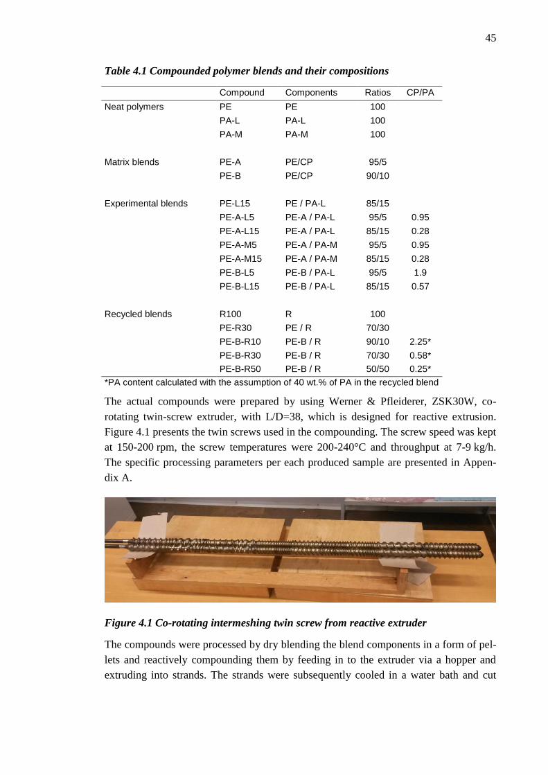
45
Table 4.1 Compounded polymer blends and their compositions
Compound Components Ratios CP/PA
Neat polymers PE PE 100
PA-L PA-L 100
PA-M PA-M 100
Matrix blends PE-A PE/CP 95/5
PE-B PE/CP 90/10
Experimental blends PE-L15 PE / PA-L 85/15
PE-A-L5 PE-A / PA-L 95/5 0.95
PE-A-L15 PE-A / PA-L 85/15 0.28
PE-A-M5 PE-A / PA-M 95/5 0.95
PE-A-M15 PE-A / PA-M 85/15 0.28
PE-B-L5 PE-B / PA-L 95/5 1.9
PE-B-L15 PE-B / PA-L 85/15 0.57
Recycled blends R100 R 100
PE-R30 PE / R 70/30
PE-B-R10 PE-B / R 90/10 2.25*
PE-B-R30 PE-B / R 70/30 0.58*
PE-B-R50 PE-B / R 50/50 0.25*
*PA content calculated with the assumption of 40 wt.% of PA in the recycled blend
The actual compounds were prepared by using Werner & Pfleiderer, ZSK30W, co-
rotating twin-screw extruder, with L/D=38, which is designed for reactive extrusion.
Figure 4.1 presents the twin screws used in the compounding. The screw speed was kept
at 150-200 rpm, the screw temperatures were 200-240°C and throughput at 7-9 kg/h.
The specific processing parameters per each produced sample are presented in Appen-
dix A.
Figure 4.1 Co-rotating intermeshing twin screw from reactive extruder
The compounds were processed by dry blending the blend components in a form of pel-
lets and reactively compounding them by feeding in to the extruder via a hopper and
extruding into strands. The strands were subsequently cooled in a water bath and cut

46
into small pellets by strand pelletizer. A schematic presentation of the compounding and
pelletizing process is presented in Figure 4.2.
Figure 4.2 Compounding and pelletizing process
The matrix compounds were prepared by dry blending the neat polyethylene with 5 and
10 wt.% of maleic anhydride grafted compatibilizer precursor, CP and processing the
blends through the extruder. After this, the matrix compounds were blended in different
ratios with low viscosity polyamide, PA-L and medium viscosity polyamide, PA-M.
The polyamide grades were dried for approximately 15 hours at 75 °C in order to re-
move the excess moisture as polyamide is a hydrophilic material and the excess mois-
ture could cause volatilities during processing and cause hydrolysis in the PA chains.
The compounds with PE and the recycled material were prepared in a same manner.
4.2.3 Sample pressing and cutting
The specimens for mechanical testing were prepared by compression moulding. The
compounded pellets were pressed into 4 mm thick sheets by using two Teflon coated
metal sheets and a rectangular mould under a specific compressing program presented
in Figure 4.3. The maximum temperature during the program was 210 °C and the pres-
sure applied was 5.0 bar.

47
Figure 4.3 Compression moulding program
The dumbbell shaped test specimens for tensile tests were die cut from the sheets by
using a specific die for the specimens defined in the standard ISO 527-1. The specimens
for the Charpy impact tests were cut to the required dimensions according to the stand-
ard ISO 179-1 by using a circular saw.
4.2.4 Film manufacturing
Some of the produced compounds were converted into a form of film in order to analyse
the homogeneity of the compounds. The converting was conducted by using Dr. Collin
ESC T10 cast film extruder, which is presented in Figure 4.4. The compounds convert-
ed into film and the processing parameters that were used are presented in Table 4.2.
0
1
2
3
4
5
6
0
50
100
150
200
0 5 10 15 20 25 30 35 40
Pre
ssu
re [
bar
]
Tem
pe
ratu
re [
°C]
Temperature Pressure

48
Figure 4.4 Cast film extrusion equipment
Table 4.2 Processing parameters
Screw
speed [rpm]
Screw Temp.
Profile [°C]
Yield
[kg/h]
Film Thickness
[μm]
PE 23 175-240 1.8 41.8
PE-L15 34 175-270 3.5 476
PE-A-L15 31 175-270 2.8 170.9
PE-A-M15 31 175-270 1.9 166.7
PE-B-L15 31 175-270 2.8 93.4
PE-R30 31 175-270 2.6 67.6
PE-B-R30 31 175-270 1.7 121.7
Prior to the processing the granules were dried in a Heraeus vacuum oven at 80 °C for at
least 45 minutes. The compounds were then fed into the hopper and extruded through an
about 18 cm wide die on a cast chill roll (at temperatures 70 or 75 °C, depending on the
compound). As the goal was to produce uniform film without holes and other defects
some of the processing parameters had to be adjusted slightly depending on the com-
pounds so that the converting was successful. Important factors were the temperature
and speed of the chill rolls and the use of air knife after the die. Due to the small batch
sizes of the studied compounds the optimization of the film conversion process was not
possible and thus the same film thickness for all film samples was not reached.
4.3 Test methods
This section presents the test methods used to characterize the produced compounds.
Impact and tensile tests are mechanical tests which give indications of the adhesion be-
tween the matrix and the dispersed phase. Optical microscopy and SEM analysis were

49
conducted for the evaluation of the compound morphology. Melt flow rate and DSC
give indications of the structures of the compound components.
4.3.1 Impact test
The Charpy impact strength of the produced compounds was measured according the
ISO standard ISO 179-1 Plastics – Determination of Charpy impact properties – Part 1:
Non-instrumented impact test. The standard specifies a method for determining the
Charpy impact strength of plastics under defined conditions. The method can be used to
investigate the behaviour of specified types of specimen under the impact conditions
defined and for estimating the brittleness or toughness of specimens within the limita-
tions inherent in the test conditions. [100]
Prior to testing the specimens machined from the compress moulded sheets into ISO
179-1/1eA specimens, with the dimensions of: length l = 80 ± 2 mm, width, b = 10.0 ±
0.2 mm and thickness, h = 4.0 ± 0.2 mm. The type A notch with depth of 2 ± 0.2 mm
and the notch tip radius of rN = 0.25 ± 0.05 mm was machined on the edge of the speci-
men. The specimens were conditioned in the standard atmosphere (23 ± 2 °C and 50 ±
5 % of relative humidity) for at least 16 hours prior to testing.
The tests were also conducted in the standard atmosphere by using Zwick pendulum-
type testing machine and a 4.0 kJ hammer. At least 10 specimens were tested per sam-
ple. After the impact the break types were assessed visually between the categories
complete break, CB, hinge break, HB, partial break, PB and no break, NB.
4.3.2 Tensile test
The tensile properties of the studied compounds were determined according to ISO 527-
1 Plastics – Determination of tensile properties – Part 1: General principles. The stand-
ard specifies the general principles for the testing procedure, conditions and the test
specimens. [101]
The tensile specimens were die cut from the produced 4 mm thick sheets by using a
specific die for dumbbell shaped 1A test specimen according to ISO 527-2. Prior to test-
ing the specimens were conditioned for at least 16 hours in the standard atmosphere and
the tests were conducted in the same atmospheric conditions.
The tensile tests were conducted by using Zwick/Roell universal testing machine. At
least 5 specimens were tested for each sample and the results are presented as the aver-
age of these 5 results. The test speed was 1 mm/min until the tensile modulus, that is,
until the elongation of 0.25 % and after that the speed was 50 mm/min. The properties
studied in the tensile test were tensile modulus (Et), tensile stress (σM), stress at yield

50
(σY), elongation at yield (εY), stress at break (σB), elongation at break (εB), and nominal
elongation at break (εtB).
4.3.3 Microscopy
The morphology of the studied compounds was analysed by optical microscopy and
electron microscopy. The optical microscopy analysis was performed on the films pro-
duced from the selected compounds using the optical microscope Reichert –Jung
Polyvar-Met. The analysed samples were prepared by cutting thin slices if the films
perpendicular to the machine direction of the film. The film surface was characterized
by using Nikon SMZ1500 optical microscope.
The morphology of the produced films was examined also by using field emission FEI
Quanta 200 FEG scanning electron microscope operating at 7.5 kV. Prior to analysis the
films were cryo-fractured under liquid nitrogen and the fracture surfaces were coated
thinly with a gold/palladium alloy.
4.3.4 Melt flow rate
The Melt flow rate of the compounds was studied according to the standard SFS-EN
ISO 1133-1 Plastics – Determination of the melt mass-flow rate (MFR) and melt vol-
ume-flow rate (MVR) of thermoplastics – Part 1: Standard method. The standard speci-
fies the methods for determination of the melt mass flow rate (MFR) of thermoplastic
materials under specific conditions of temperature and load. [102]
The measurements were conducted under 2.16 kg weight at the temperature of 230 °C.
The melt flow rates of the compounds were analysed by measuring the weight of the
extrudate coming through the die within 1.0 minute, taking an average on 3 measure-
ments and multiplying the value by 10 to get the final value for the melt flow in 10
minutes.
4.3.5 Differential scanning calorimetry
The thermal properties of the compounds were studied by differential scanning calorim-
etry, DSC, according to the standard SFS-EN ISO 11357 Plastics. Differential scanning
calorimetry (DSC). The standard specifies the methods for the thermal analysis of the
polymers and polymer blends and it can be used for the observations of different physi-
cal transitions, such as glass transition, melting and crystallization, and the heat capaci-
ty. [103]
Prior to the DSC analysis the studied samples were homogenized by using the MFR
device. The Mettler-Toledo Differential scanning calorimeter was used in the analysis
of the thermal properties in nitrogen atmosphere with 50.0 ml/min flux and the device

51
was calibrated against certified indium reference The samples were scanned at heating
rate of 10.0 °C/min and heated from 30 to 225 °C and held at this temperature for
5.0 minutes to erase the thermal history during processing. The samples were then
cooled at the rate of 10.0 °C/min until 30 °C and again after holding at this temperature
for 5.0 minutes the samples were heated again until 225 °C following the same heating
rate as on the first scan. The heat flow during the scans was recorded and the data was
analysed by using STARe SW 8.10 thermal analysis software.

52
5. RESULTS AND DISCUSSION
The most important results obtained in the experimental part are presented in this chap-
ter. The results are divided in following sections: visual observations, mechanical prop-
erties, morphology of the compounds and melt flow and thermal properties.
5.1 Visual observations
The pelletized compounds and neat polymers are presented in Figure 5.1. It can be seen
already from the pellets how the colours of the compounds differ. The neat polymers
PE, PA-L and PA-M and the matrix compounds PE-A and PE-B have a white, “natural”
colour and the blends with the matrix compounds and the neat polyamides are slightly
yellowish. The blends with recycled material have darker, brown colour.
Figure 5.1 Pelletized compounds. Top row from left: PE, PA-L, PA-M, PE-B, PE-A,
PE-L15, PE-A-M5 and PE-A-M15. Bottom row: PE-A-L5, PE-A-L15, PE-B-L5, PE-
B-L15, R100, PE-R30, PE-B-R10, PE-B-R30 and PE-B-R50
After the pellets were compressed into sheets the evaluation of the colour was easier as
the studied surface was larger. The same differences were observed as with the pellets,
but in addition to the colour, the homogeneity of the colour was also possible to evalu-
ate visually. The compressed sheets are presented in Figure 5.2.

53
Figure 5.2 Compounds pressed into 16x35 cm sheets.
The colour difference between the compounds is amplified when compressed into
sheets. The difference between the natural colour of the PE and matrix compounds and
the yellowish colour of the virgin matrix/PA blends is obvious. It can also be seen in
Figure 5.2 how the compatibilized compounds containing 15 wt.% of PA have a slightly
lighter colour than the compounds containing only 5 wt.% of PA. The R100 blend con-
sisting only of the recycled film material has a strong yellow colour with darker brown
patches. The blends with the PE-B matrix and the recycled blend have the darker colour
the larger the recycled content is.
The colouring of the compounds containing matrix compounds and neat PA is probably
due to some type of material degradation and oxidation in the blend during compound-
ing. The stronger the colouring of the compounds containing recycled material could be
due to the degradation and oxidation of the unknown additives or tie-layers in the recy-
cled blends, as the colour darkens by the increase of the content of the recycled blend.
The same type of uneven colouring as observed in the R100 recycled blend was ob-
served the uncompatibilized blend on PE and 15 wt.% of low viscosity PA, but the col-
our differences in the blend were lighter. This uneven colour is an indication of hetero-
geneous blend morphology and lack of adhesion between the phases.
5.2 Mechanical properties
Mechanical properties of the compounds were characterized by Charpy impact test and
tensile test. The results of these characterisations are presented and evaluated in follow-
ing sub-sections.
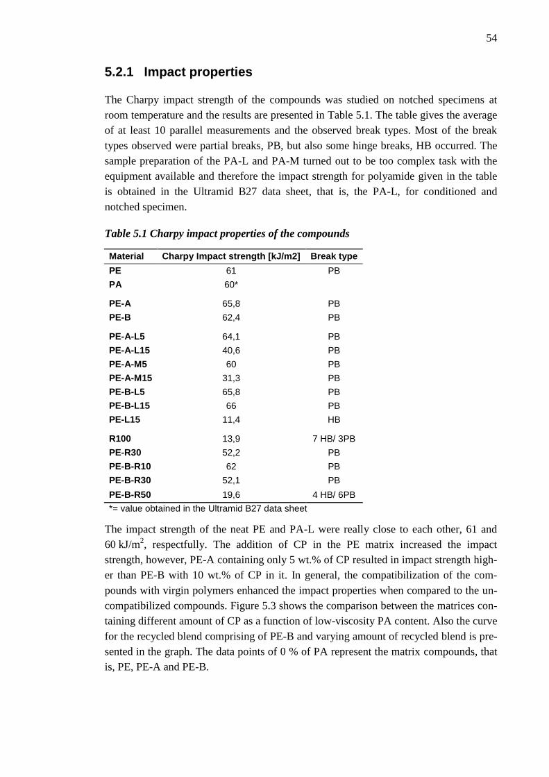
54
5.2.1 Impact properties
The Charpy impact strength of the compounds was studied on notched specimens at
room temperature and the results are presented in Table 5.1. The table gives the average
of at least 10 parallel measurements and the observed break types. Most of the break
types observed were partial breaks, PB, but also some hinge breaks, HB occurred. The
sample preparation of the PA-L and PA-M turned out to be too complex task with the
equipment available and therefore the impact strength for polyamide given in the table
is obtained in the Ultramid B27 data sheet, that is, the PA-L, for conditioned and
notched specimen.
Table 5.1 Charpy impact properties of the compounds
Material Charpy Impact strength [kJ/m2] Break type
PE 61 PB
PA 60*
PE-A 65,8 PB
PE-B 62,4 PB
PE-A-L5 64,1 PB
PE-A-L15 40,6 PB
PE-A-M5 60 PB
PE-A-M15 31,3 PB
PE-B-L5 65,8 PB
PE-B-L15 66 PB
PE-L15 11,4 HB
R100 13,9 7 HB/ 3PB
PE-R30 52,2 PB
PE-B-R10 62 PB
PE-B-R30 52,1 PB
PE-B-R50 19,6 4 HB/ 6PB
*= value obtained in the Ultramid B27 data sheet
The impact strength of the neat PE and PA-L were really close to each other, 61 and
60 kJ/m2, respectfully. The addition of CP in the PE matrix increased the impact
strength, however, PE-A containing only 5 wt.% of CP resulted in impact strength high-
er than PE-B with 10 wt.% of CP in it. In general, the compatibilization of the com-
pounds with virgin polymers enhanced the impact properties when compared to the un-
compatibilized compounds. Figure 5.3 shows the comparison between the matrices con-
taining different amount of CP as a function of low-viscosity PA content. Also the curve
for the recycled blend comprising of PE-B and varying amount of recycled blend is pre-
sented in the graph. The data points of 0 % of PA represent the matrix compounds, that
is, PE, PE-A and PE-B.

55
Figure 5.3 Charpy Impact Strength as a function of PA content
It can be seen in the Figure 5.3 that the uncompatibilized blend had a rapid decrease
from 60 to 11.4 kJ/m2 in the impact strength as the content of PA in the compound in-
creased to 15 wt.%. This is most presumably due to the weak adhesion between the PE
and PA phases and due to the inhomogeneous morphology of the compound. The com-
pounds with PE-A matrix experienced also a loss in the impact strength with increased
PA content: At PA content of 5 wt.% the strength had decreased only slightly, presuma-
bly due to the high CP/PA ratio in the blend an thus due to the successful compatibiliza-
tion resulting from it. At 15 wt.% of PA the CP/PA ratio is only 1/3 of the PE-A-L5 and
the impact strength has decreased almost 40% from that of neat PE-A matrix com-
pound. With the PE-B matrix compounds the added PA in the blend seemed to increase
the impact strength. Both blends, with 5 and 15 wt.% of PA had the impact strength of
approximately 66 kJ/m2 which is about 6% higher than that of the neat PE-B matrix.
The studies of Burgstaller et al. [9] support these observations of rapidly decreasing
impact strength of uncompatibilized PE/PA blend with increasing PA content (up to 20
wt.% of PA) and the slowly increasing or decreasing impact strength of the compatibil-
ized blends, depending on the compatibilization method. However, the neat PA used in
their studies exhibited significantly higher impact strength than that of PE they used,
and even in the case with increasing impact strength with increasing PA content the
measured values were merely following a linear increase towards the values of neat PA
and no values over this imaginary line is observed. This is interesting because in the
compounds studied in this thesis the impact strength of the some of the produced com-
pounds is higher than those of any the blend components.
When the compounds with 15% of PA are compared, already 5% of CP in the matrix
gives an increase of approximately 250% in the Charpy impact strength and 10 % of CP
in the matrix increases the impact strength from the non-compatibilized blend almost
0
10
20
30
40
50
60
70
0 5 10 15 20
Ch
arp
y Im
pac
t St
ren
gth
[kJ
/m2
]
PA content [wt.%]
no CP in matrix
5% of CP in matrix
10% of CP in matrix
10% of CP in matrix, Recycled PA

56
480%. The reason for this is in the toughening effect of the small dispersed PA droplets,
and with finer structure and increased adhesion between the phases as the impact re-
sistance is higher than for the less compatibilized blends with larger dispersed particles
and possibly smaller adhesion between the phases to prevent the crack propagation.
It can be also argued if the compression moulding method of the test specimens with the
compression temperature 10 °C lower than the actual melting temperature of PA has
some effect on the impact properties. As some parts of the PA phase are not molten dur-
ing the compression moulding this could have an effect on the flow properties of the
blends as it takes the form of the mould and thus on the morphology. It is also possible
that if the morphology formed during compounding was not stable the subsequent heat-
ing would stabilize the structures and for example some coalescence of the PA droplets
could occur. This effect, however, is present in all samples as the compression process
was the same for all the compounds.
The compounds with the PE-B matrix and the recycled material as the minor phase
showed a decrease in the impact strength with the increased content of the recycled ma-
terial, and thus also by the increasing PA content. A comparison between all the blends
containing recycled material is presented in Figure 5.4. In general the dominating effect
of the matrix material is well seen as by the increasing content of the recycled material
the impact strength decreases. The compound with the least recycled content (and least
PA) is PE-B-R10 and it has the highest observed impact strength of the recycled com-
pounds, that is, 62 kJ/m2. This is about the same than that of the matrix compound PE-
B, which indicates that small amounts of the recycled material in the matrix do not af-
fect the impact properties. 30 wt.% of the recycled material in the compound resulted in
approximately 15 % lower impact strength than the neat PE. Despite the prominent dif-
ference in the PA content the recycled blend R100 with about 40 wt.% of PA in it re-
sults in impact strength of 13.9 kJ/m2 which is still over 20 % higher than the impact
strength of the uncompatibilized PE-L15. Also the PE-B-R50 with PA content of ap-
proximately 20 wt. % has almost double the impact strength than that of PE-L15.
The compatibilization of the recycled blend showed little effect as the compatibilized
and uncompatibilized blends with 30 wt.% of the recycled blend had the same impact
strength with each other. The impact strength of the compounds was about 14 % smaller
than with virgin PE. The lack of difference between the compatibilized and uncompati-
bilized blends could be due to the adhesive materials already present in the recycled
film material which could possibly also act as some sort of compatibilizing agents in the
blend and thus no extra CP would be needed to stabilize the morphology.

57
Figure 5.4 Charpy impact strength of blends containing recycled material
When the impact strength of the studied compounds is presented as a function of the
CP/PA ratio, a different type of comparison between the virgin and recycled materials
can be done. As presented in Figure 5.5 the trends of the data points of both virgin low
viscosity PA and recycled PA from the recycled film material are approximately the
same, the virgin PA only gives slightly higher values especially at low CP/PA values.
For example at CP/PA ratio a bit over 0.5, that is twice as much PA than CP in the
compound, containing recycled PA gives only 52.1 kJ/m2 impact strength whereas
compound with PA-L results in 66 kJ/m2. The higher the CP/PA ratio is the closer the
impact strength values are the values of PE. This was expected because with high
CP/PA ratio there is significantly more CP than PA and therefore there is also signifi-
cantly more PE in the compound as the CP is part of the matrix compound. This analy-
sis, however, does not take into account the possible additional adhesives in the recy-
cled blend which would increase the CP/PA ratios for the recycled blend. It can, howev-
er, be said that within the measurement inaccuracies trend is similar for both cases.
13,9
52,2
62
52,1
19,6
0
10
20
30
40
50
60
70
Recycledblend
PE matrix,30%
recycled
10% of CPin matrix,
10 %recycled
10% of CPin matrix,
30 %recycled
10% of CPin matrix,
50 %recycled
Ch
arp
y Im
pac
t St
ren
gth
[kJ
/m2
]
Recycled PE

58
Figure 5.5 Charpy impact strength of the compounds as a function of the weight ratio
of compatibilizer precursor to polyamide
The effect of the viscosity of polyamide is presented in Figure 5.6. The compounds of
PE-A with 5% of CP and two different polyamides with different melt viscosities, PA-L
with low melt viscosity and PA-M with medium viscosity were studied. The compounds
with PA-L showed smaller decrease in the impact strength with increased PA content
than the compounds with the medium viscosity PA-M.
Figure 5.6 Charpy impact strength of the compounds containing 5 wt.% of CP and
low viscosity PA or medium viscosity PA
With mainly linear PA6 the lower viscosity is usually related to smaller molecule
weight. This means that with the same weight of low and medium viscosity polyamides
the lower viscosity PA has shorter chains and thus higher concentration of the -NH2
amine end groups. These groups can therefore potentially form more bonds with the
anhydride moieties in the CP and thereby form the compatibilizing graft copolymers.
0
10
20
30
40
50
60
70
0 0,5 1 1,5 2 2,5
Ch
arp
y im
pac
t St
ren
gth
[kJ
/m2
]
CP/PA
PE
Low viscosity PA
Recycled PA
65,8 64,1
40,6
65,8 60
31,3
0
10
20
30
40
50
60
70
80
no PA 5 % of PA 15 % of PA
Ch
arp
y Im
pac
t St
ren
gth
[kJ
/m2
]
Low viscosity PA Medium viscosity PA

59
And hence, the better impact properties of the compounds with lower viscosity PA
could be explained.
Altogether, the virgin polymers PE and PA-L exhibited rather similar impact strength.
The addition of PA to uncompatibilized PE matrix decreased the impact properties dras-
tically. The compatibilization of the blends decreased the loss if impact strength by in-
creasing PA content for the compounds with only 5 wt.% of CP in the matrix and for
the compounds with the recycled material as the minor phase. The virgin compounds
with PE-B showed higher impact strength than those of neat PE or PA which owes pre-
sumably to the high interactions between the phases due to the formation of compatibil-
izer at the phase interface and the reinforcing effect of the small PA droplets in the PE
matrix. The blends with recycled material did not show any effect with the addition of
CP in the compound. The most significant factor for the impact properties seemed to be
the CP/PA ratio which followed the same trend, no matter if the PA in the blend was
virgin or recycled.
5.2.2 Tensile properties
The tensile properties of the prepared compounds were studied according to the proce-
dure described earlier. The obtained effects of the blend composition on the tensile
modulus (Et), ultimate tensile strength, that is, the maximum stress (σM), nominal strain
at break (εtB), stress at yield (σY), elongation at yield (εY), stress at break (σB), and strain
at break (εB) are presented in Table 5.2. The results show that the increasing PA content
stiffens the material as tensile modulus and stress at yield increase by increasing PA
content. At the same time the tensile strength and the strains at yield and break decrease.
Different types of behaviour under tension were obtained in the tensile tests and some
examples of the typical stress – strain curves obtained are presented in Figure 5.7. The
scale of the different tensile behaviours was broad ranging from rigid recycled R100
blend breaking just after yielding to compound PE-A-M15 with the max stress achieved
at yield and further on to the highly stretchy behaviour of PE and the matrix materials
PE-A and PE-B which did not break even at the strain of 800 % but slipped away from
the clamps of the testing machine as the tensile specimens thinned duo to the excess
strain.

60
Table 5.2 Tensile properties of the compounds
Material
Tensile
Modulus
[MPa]
Tensile
strength
[MPa]
Nominal
Strain at
break [%]
Stress
at Yield
[MPa]
Strain at
Yield
[%]
Stress at
Break
[MPa]
Strain at
Break
[%]
PE 342 24,5 800 11,3 14 24,5 800
PA 1000* 50* 45* 20*
PE-A 350 23,8 790 11,4 14 23,8 800
PE-B 357 24,2 820 11,5 14 24,2 830
PE-A-L5 428 20,1 590 12,2 11 20,1 590
PE-A-L15 504 15.3 410 13,26 10,6 15,26 412
PE-A-M5 415 22,2 700 12,1 11 22,2 710
PE-A-M15 513 13,3 270 13,3 10 11,9 270
PE-B-L5 410 21,9 690 12,1 11 21,9 700
PE-B-L15 488 17 420 13,3 10 17 430
PE-L15 524 13,2 8,9 13,2 6,9 12,9 10
R100 436 11,7 19 11,7 20,4 11,7 23
PE-R30 424 15,5 440 12,3 13 15,5 450
PE-B-R10 372 23,2 760 11,6 13 23,2 760
PE-B-R30 410 15,6 450 12,1 14 15,6 450
PE-B-R50 450 12,9 71 12,9 15,1 11,7 76
*= value obtained in the Ultramid B27 data sheet
Figure 5.7 Typical stress - strain curves for tensile tests
Figure 5.8 presents the tensile modulus as a function of the content of PA-L or the recy-
cled PA. All matrices exhibited Et around 350 MPa. The increase of the tensile modulus
as a function of PA content was rather linear, and no significant differences between the
0
5
10
15
20
25
30
0 100 200 300 400 500 600 700 800
Stan
dar
d F
orc
e [
MP
a]
Strain [%]
PE-L15 PE PE-B-L15 PE-A-M15 PE-B-R50 R100

61
different matrices were observed. When the observed Et values are compared to the neat
PE the addition of 15 % of PA increased the tensile modulus with 43 % with 10 % of
CP in the matrix, 47 % with 5 % of CP in the matrix and up to 53 % without any CP.
This means that the uncompatibilized blend is slightly more rigid and the addition of CP
increases the elasticity of the compound by decreasing the tensile modulus. The results
of increasing tensile modulus by increasing PA content in compatibilized and uncom-
patibilized blends are supported by the reported results of Burgstaller et al. [9]. Their
findings, however, showed that the blends compatibilized with PE-g-MA compatibilizer
precursor followed the same trend as the uncompatibilized blend, which is not totally in
alignment with the results in this thesis, even though, the observed difference was rather
small. Filippi et al. [11], on the other hand, have reported on the same type of decrease
in the tensile modulus when the PE/PA ratio is kept constant and the only the content of
CP is increased.
Figure 5.8 Tensile Modulus as a function of PA content
The compounds containing recycled material did not show the same amount of increase
in the tensile modulus as the blends with virgin material, as shown in Figure 5.8. The
interpolated value for the PA content of 15 wt.% is approximately 430 MPa which cor-
responds to only 26 % increase to the virgin PE and is about half of the increase ob-
tained in the uncompatibilized compound with equivalent amount of PA. Even the com-
pound containing 20 % of recycled PA, Et=450 MPa, does not reach the tensile modulus
values of the compounds with virgin materials at PA content of 15 wt.% of PA. This is
probably due to the LDPE and LLDPE in recycled blend which normally exhibit lower
Et and therefore have their own contribution to the properties of the blend.
The stress at yield and strain at yield of all the compounds with virgin materials follow
the same trends, as shown in Figure 5.9 and Figure 5.10. The stress at yield increases
fairly linearly as a function of PA content from about 11.5 MPa with the pure matrix
300
350
400
450
500
550
0 5 10 15 20
Ten
sile
Mo
du
lus
[MP
a]
PA content [wt.%]
no CP in matrix 5% of CP in matrix
10% of CP in matrix 10% of CP in matrix, recycled PA

62
materials until 13.3 MPa with 15 wt.% of PA. The compatibilization of the virgin
blends shows no effect on σy. The strain at yield of the uncompatibilized blend decreas-
es by 50 % with the addition of 15 wt.% of PA. The addition of CP stabilizes the struc-
ture slightly and the decrease is only about 30 %. However, it has to be remembered
that the elongation at yield is measured in percentage and as the measured elongations
are small, already a difference of 1 or 2 percentage points makes a significant differ-
ence.
Figure 5.9 Stress at yield as a function of PA content
Figure 5.10 Strain at yield as a function of PA content
The compounds with recycled material differ by the stress at yield and strain at yield
behaviour from the blends with virgin materials. The stress at yield increased by the
increase of the PA content more moderately and for example the same stress at yield
values achieved with the addition of only 5 % of virgin PA are reached with recycled
material with approximately 12 wt.% content of PA. With the 50/50 blend of PE-B and
11
11,5
12
12,5
13
13,5
0 5 10 15 20
Stre
ss a
t Y
ield
[M
Pa]
PA content [wt.%] no CP in matrix 5% of CP in matrix
10% of CP in matrix 10% of CP in matrix, recycled PA
0
2
4
6
8
10
12
14
16
0 5 10 15 20
Stra
in a
t Y
ield
[%
]
PA content [wt.%] 5% of CP in matrix 10% of CP in matrix
no CP in matrix 10% of CP in matrix, recycled PA

63
recycled material the PA content is about 20 wt.% and the strain at yield is 15 %, which
is even higher than those of matrix materials. The differences between the virgin and
recycled compounds are again probably due to the other polymers in the recycled blend
which affect the blend behaviour more than for example compatibilization. Araújo et al.
[4] named the stress at yield as a limiting property and therefore proportional to the de-
gree of adhesion in the blend interface. In their studies they observed increased yield
stress with the use of CP, which is opposite to the observations in this thesis. The results
observed in this thesis follow more the behaviour of uncompatibilized blend observed in
the studies on Araújo et al. Based on their conclusions this indicates a lack of adhesion
between the phases as the compatibilizer has not localized on the interfaces. The recy-
cled blends, on the other hand show increased yield stress, which support the findings of
Araújo et al.
The strain at break and the ultimate tensile strength of the studied compounds de-
creased both by the increased polyamide content as shown in Figure 5.11 and Figure
5.12. The decreasing rate of the compatibilized blends and the blends with recycled ma-
terial were approximately the same, whereas the uncompatibilized blend showed promi-
nently faster decreasing rate as the addition of 15% of PA resulted in 10 % strain at
break. The compatibilization of the blends increased the maximum strain of the 85/15
PE/PA blend from 10 to over 400 %. Filippi et al. [11] demonstrated the similar type of
significant increase in elongation with the addition of CP when 75/25 LDPE/PA6 blend
was studied. The compatibilization of the blends was suggested to enhance the interfa-
cial adhesion in the compatibilized samples and, thus, increase the observed strains.
Figure 5.11 Strain at break as a function of PA content
0
100
200
300
400
500
600
700
800
900
0 5 10 15 20
Stra
in a
t B
reak
[%
]
PA content [wt.%] 5% of CP in matrix 10% of CP in matrix
no CP in matrix 10% of CP in matrix, recycled PA
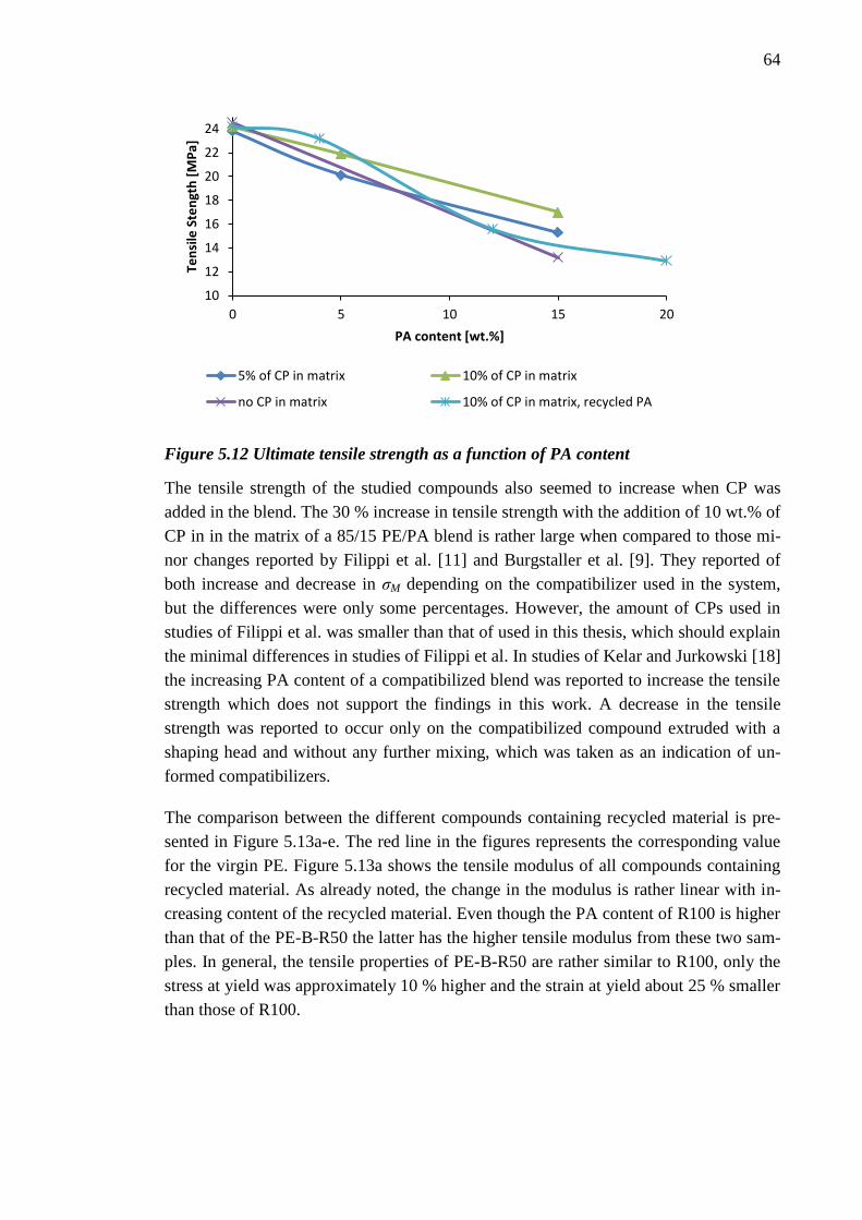
64
Figure 5.12 Ultimate tensile strength as a function of PA content
The tensile strength of the studied compounds also seemed to increase when CP was
added in the blend. The 30 % increase in tensile strength with the addition of 10 wt.% of
CP in in the matrix of a 85/15 PE/PA blend is rather large when compared to those mi-
nor changes reported by Filippi et al. [11] and Burgstaller et al. [9]. They reported of
both increase and decrease in σM depending on the compatibilizer used in the system,
but the differences were only some percentages. However, the amount of CPs used in
studies of Filippi et al. was smaller than that of used in this thesis, which should explain
the minimal differences in studies of Filippi et al. In studies of Kelar and Jurkowski [18]
the increasing PA content of a compatibilized blend was reported to increase the tensile
strength which does not support the findings in this work. A decrease in the tensile
strength was reported to occur only on the compatibilized compound extruded with a
shaping head and without any further mixing, which was taken as an indication of un-
formed compatibilizers.
The comparison between the different compounds containing recycled material is pre-
sented in Figure 5.13a-e. The red line in the figures represents the corresponding value
for the virgin PE. Figure 5.13a shows the tensile modulus of all compounds containing
recycled material. As already noted, the change in the modulus is rather linear with in-
creasing content of the recycled material. Even though the PA content of R100 is higher
than that of the PE-B-R50 the latter has the higher tensile modulus from these two sam-
ples. In general, the tensile properties of PE-B-R50 are rather similar to R100, only the
stress at yield was approximately 10 % higher and the strain at yield about 25 % smaller
than those of R100.
10
12
14
16
18
20
22
24
0 5 10 15 20
Ten
sile
Ste
ngt
h [
MP
a]
PA content [wt.%]
5% of CP in matrix 10% of CP in matrix
no CP in matrix 10% of CP in matrix, recycled PA

65
a) b)
Figure 5.13 Tensile properties of the blends with recycled material (a) Tensile Modu-
lus, (b) Stress at Yield, (c) Strain at Yield, (d) Tensile Strength and, (e) Strain at
Break
436 424
372
410
450
300320340360380400420440460480
Ten
sile
Mo
du
lus
[MP
a]
11,7 12,3
11,6
12,1
12,9
10,0
10,5
11,0
11,5
12,0
12,5
13,0
13,5
Stre
ss a
t Y
ield
[M
Pa]
20,4
13 13 14 15,1
0,0
5,0
10,0
15,0
20,0
25,0
30,0
Stra
in a
t Y
ield
[%
]
11,7
15,5
23,2
15,6 12,9
0
5
10
15
20
25
Ten
sile
Str
en
gth
[M
Pa]
23
450
760
450
76
0100200300400500600700800900
Star
in a
t B
reak
[%
]
Recycled
PE
c) d)
e)

66
The most significant observation in the results presented in Figure 5.13 was again the
lack of difference between the tensile properties of the compatibilized and uncompati-
bilized compounds containing 30 wt.% of recycled materials as for example the tensile
modulus of the un-compatibilized blend was only about 3% higher than the correspond-
ing value for compatibilized blend. Therefore, it can be said that the differences be-
tween the compatibilized and uncompatibilized 70/30 PE-B/Recycled material blends
are negligible.
The tensile properties were also evaluated in the relation to the CP/PA ratio of the com-
pounds. Figure 5.14 represents the tensile modulus (Figure 5.14a), ultimate tensile
strength (Figure 5.14b), stress at yield (Figure 5.14c), strain at yield (Figure 5.14d) and
strain at break (Figure 5.14e) as a function of the CP/PA ratio. The PA content was cal-
culated for the compounds containing low viscosity PA and for the blends containing
recycled material. As before, the PA content of the recycled material was assumed to be
approximately 40 wt.% and, thus, for example the PA content of the PE-B-R30 blend
was around 12 wt.%.
The graphs in Figure 5.14 show that the recycled and virgin PA follow about the same
trends as the other in all but one tensile property, that is, the strain at yield, in which the
blends containing recycled PA seem to yield at somewhat higher strains than the blends
containing virgin PA-L. The tensile strength and strain at break seem to increase as the
CP/PA ratio increases. In other words, the more there is CP in the blend and less there is
PA the higher the strain at break or tensile strength are. The low CP/PA ratio results in
small strains and lower tensile strength. However, usually the content of PE increases at
the same time as the amount of CP and thereby the ratio of PE/PA might also affect the
result. In tensile modulus, stress at yield and strain at yield the obtained values seem to
be rather unaffected by the CP/PA ratio. However, at the CP/PA values under 1, that is,
more PA than CP there is more deviation. At CP/PA values closer to 2 there is twice as
much (when measured in weight) CP than PA which means with the amounts used in
the studied blends that the overall content of the PA in these blends are relatively low
and thereby the PE content is naturally high. Thus, it is expected that the properties are
close to that of PE.
When the blends with PA-L and PA-M as a minor component in the compound were
compared, no significant differences were obtained. The tensile properties of the com-
pounds comprising of PE-A matrix material and 5 or 15 % of polyamide are presented
in Appendix B. The only noticeable differences are in the maximum properties, that is,
the ultimate tensile strength and strain at break. In these both the compounds with 5% of
PA the medium viscosity PA yields in higher values than the low viscosity PA whereas
with 15 % of PA the PA-L gives higher values than PA-M. However, the deviations of
the results are in a range that could make these differences rather small if both in their
upper and lower limits, respectively.

67
a) b)
b)
Figure 5.14 Tensile properties as a function of CP/PA ratio (a) Tensile Modulus, (b)
Tensile Strength, (c) Stress at Yield, (d) Strain at yield and (e) Strain at Break
In general, the tensile properties show a strong dependence on the PA content and no
matter if the blend is compatibilized or uncompatibilized. The increased mechanical
properties by the addition of CP are an indication of a successful compatibilization of
the virgin compounds. However, the content of CP did not show a big effect on the ten-
sile properties as the compounds with PE-A and PE-B matrices resulted in rather identi-
cal results. The recycled materials did not show any significant differences between the
compatibilized and uncompatibilized PE matrix.
0
100
200
300
400
500
600
0 1 2
Ten
sile
Mo
du
lus
[MP
a]
CP / PA
0
5
10
15
20
25
30
0 1 2
Ten
sile
Str
en
gth
[M
Pa]
CP / PA
0
2
4
6
8
10
12
14
0 1 2
Stre
ss a
t Y
ield
[M
Pa]
CP / PA
0
5
10
15
20
0 1 2
Stra
in a
t Y
ield
[%
]
CP / PA
0
200
400
600
800
1000
0 1 2
Stra
in a
t B
reak
[%
]
CP / PA
Low viscosity PARecycled PAPE
c) d)
e)

68
5.3 Morphological analysis
The effect of the CP content on the blend morphology was evaluated from a selection of
compounds converted into a form of film. The morphology of the selected compounds
containing 15 wt.% of PA or 30 wt.% of the recycled material was analysed by using
light microscopy and SEM analysis. In general, the all the studied compounds showed a
morphology in which polyethylene was the continuous phase and polyamide phase was
dispersed in droplets of varying size. Due to the cast film manufacturing process the
droplets had a string-like shape oriented in machine direction. Some SEM images of the
string-like PA droplets are presented in Appendix B. The orientation and shape of the
PA droplets can also be seen Figure 5.15 presenting LM images of the film surface.
Figure 5.15 Light microscope images of the orientation and size variation of the PA
droplets on the film surface with 112.5-fold magnification
Figure 5.16a-d presents the cross section images obtained by light microscopy, LM and
Figure 5.17a-g presents SEM micrographs of the cryo-fractured fracture surfaces with
5000-fold magnification. Both sets of images clearly demonstrate the reduction in the
size of the dispersed PA droplet in the matrix when CP is added in to the virgin com-
pound, as expected. Figure 5.16a and Figure 5.17a of the binary, uncompatibilized PE-
L15 blend show the large dimensions for dispersed PA droplets. With 5 wt.% of CP in
the matrix the diameters of the PA droplets are smaller than when compared to the im-
ages of the uncompatibilized PE-L15, as seen in Figure 5.16b and Figure 5.17b. As the
CP content increases more, the size reducing effect is even stronger, as shown in Figure
5.16c and in Figure 5.17d.

69
Figure 5.16 Light microscopy images of the film cross sections of (a) PE-L15, (b) PE-
A-L15, (c) PE-B-L15 PE and (d) PE-B-R30
There are also some indications of weak adhesion between the phases. This is evident
for example in the large black areas around the PA droplets in the LM images in Figure
5.16 representing air. However, the origin of the air in the LM images is not clear as it
can be derived from the vaporized moisture in the PA phase or from the sample prepara-
tion during cutting. As no excess air was observed in the SEM micrographs between the
matrix and dispersed phase, the sample cutting would perhaps be a more potential rea-
son. Also the smooth surfaces of the PA droplets and the voids in the spots where the
droplets have separated from the matrix, as seen in the SEM micrographs are indica-
tions of weak adhesion. The signs of weak adhesion seem to decrease as the CP content
in the matrix increases. With 5 wt.% of CP in the matrix less air is observed in the cross
sectional LM images than in the uncompatibilized blend, and fewer voids and partly
pulled out droplets are present on the fracture surface of the SEM images. The Figure
5.17b of PE-A-L15 shows also the smooth surface of the exposed PA droplets. Despite
the smaller droplet size the PE-B-L15 with 10 wt.% of CP in the matrix shows also
some pulled out droplets and voids, as seen in Figure 5.16c and in Figure 5.17d.
a)
a)
b)
a)
c)
a)
d)
a)
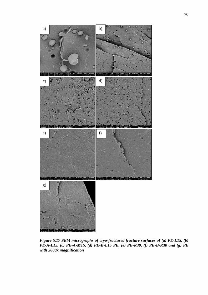
70
Figure 5.17 SEM micrographs of cryo-fractured fracture surfaces of (a) PE-L15, (b)
PE-A-L15, (c) PE-A-M15, (d) PE-B-L15 PE, (e) PE-R30, (f) PE-B-R30 and (g) PE
with 5000x magnification
a) b)
c) d)
e) f)
g)

71
As the mechanical characterisation already indicated, no evident difference between the
uncompatibilized and compatibilized recycled blends was observed, as seen in Figure
5.17e and f. The dispersed droplet size corresponds approximately to that of in the com-
pound PE-B-L15, which is demonstrated better in the LM images. The SEM micro-
graphs, on the other hand, shows a smooth fracture surface with almost none voids or
pulled out droplets, which indicates strong adhesion between the PA and the PE matrix.
This is surprising, because the compound PE-R30 does not contain any added CP in the
blend, and also because the addition of CP does not have any effect on the morphology.
As already suggested in the context of mechanical tests the adhesive material in the re-
cycled blend could have taken the role of a compatibilizer precursor and thus the added
CP is excess. This would also explain the small particle size observed in both uncom-
patibilized and in compatibilized blends as the adhesive reduces the particle size and
increases the interfacial adhesion.
Another reason for the fine morphology of the uncompatibilized recycled blend and for
the lack of change as CP is added in the compound could also be in the degraded and
oxidized blend components in the recycled material. The darker colour of the blends
with recycled material was earlier suggested to occur due to the degradation and oxida-
tion of some blend components originating from the additional processing steps of the
recycled material. As Araújo et al. [4] demonstrated the polar groups of recycled PE
formed in the oxidation can also form chemical bonds with PA and thus compatibilize
the blends of PE and PA. If the amount of oxidised substances in the compound is high
enough, no excess CP is needed to compatibilize the blend and thus this would explain
why also the uncompatibilized blend exhibits a fine morphology and the same proper-
ties as the compatibilized compound.
In general the observed droplet size of the dispersed phase in uncompatibilized and
compatibilized blends, is larger than that of reported by many papers concerning com-
patibilized blends of polyethylene and polyamide, for example by Filippi et al. [11] and
Jiang et al. [16]. For example, in studies of Filippi et al. the observed average droplet
diameter was in uncompatibilized 75/25 LDPE/PA6 blend 1.6 μm and already addition
of 1 % of CP into the blend decreased the diameter to approximately 0.5 μm. Even
though no quantitative analysis was not conducted on the droplet size in this theses, it
can be said by visual observation that the observed droplets are larger that reported by
Filippi et al. An explanation for this could be in insufficient mixing during compound-
ing. This is supported by Kelar and Jurkowski who reported [18] of a larger droplet size
and weaker adhesion between the phases in a compatibilized blend which was extruded
with shaping head and without any further mixing and they suggested that the reason for
this would have been the unformed PE-g-PA compatibilizer. However, as a reactive
twin screw with specialized mixing modules was used when compounding, a sufficient
dispersion and distribution should have been achieved also in this study. It is also possi-
ble that the conversion in to films affected the unstable morphology and the smallest

72
droplets have coalesced together during normal extrusion without further mixing as the
amount of CP has not been enough to stabilize the morphology. Nonetheless, the added
CP in the blends with virgin material was able to reduce the size of the PA droplets and
this indicates strongly that the CP was able to reduce the interfacial tension by placing
to the interface of these phases. This deduction was also supported by the results from
the mechanical characterisation.
Altogether, the morphology of the studied compounds presented PE as the continuous
matrix phase and PA as a string-like, dispersed phase. The addition of CP in the blend
reduced the size of the dispersed droplets, but the adhesion between the phases was ra-
ther weak despite the compatibilizer precursor, as even at CP content of 10 wt. % in the
matrix the SEM micrographs revealed pulled out PA droplets and voids in the places
from which the droplet had separated from the matrix. The compounds containing recy-
cled material, on the other hand, showed strong adhesion between the phases and the
sizes of the dispersed PA particles were corresponding to those of observed in the com-
pound PE-B-L15. The compatibilization on the recycled blends did not have any evi-
dent effect on the morphology, which could be due to the adhesive component in the
recycled blend acting as a compatibilizer precursor or due to the oxidized components
reacting with PA and thereby compatibilizing the blend.
5.4 Melt flow properties
The flow properties of the compounds were studied by evaluating the melt flow rate,
MFR under a 2.16 kg weight at 230 °C. The temperature of 230 °C was chosen for the
test even though the normal MRF temperature for PE is 190 °C because the melting
temperature for polyamide was 220 °C and both of the blend components had to be mol-
ten so that the MFR could be measured. These results are presented in Table 5.3.
The MFR of PE was only 0.56 g/10 min, which means that it has rather high viscosity,
at least at the test conditions. The addition of CP in PE decreased the MFR even more.
The MFR of the low viscosity PA was over 40-fold larger than that of PE and even the
medium viscosity PA had a MFR of 20-fold larger than PE. As the torque of the studied
polyamides was not measured the same type of relations between the flow properties
and morphology cannot be drawn as done in the paper of Kudva et al. [19]. They sug-
gested that the large viscosity mismatch, measurements based on the torque, between
the blend components in compatibilized blend would lead to a situation in which the
minor component with lower viscosity would drive towards being the continuous phase
already at volume fractions lower than that of calculated for phase inversion. At the
moment only conjectures can be done of the flow properties of the blend components
under the processing conditions and therefore the effects of the potential mismatch be-
tween the viscosities of the blend components on the blend morphology and thus, on the
other properties are unknown.

73
Table 5.3 MFR values of the compounds
MFR [g/10min]
PE 0.56
PA-L 23.3
PA-M 10.9
PE-A 0.53
PE-B 0.52
PE-A-L5 0.53
PE-A-L15 0.65
PE-A-M5 0.52
PE-A-M15 0.61
PE-B-L5 0.54
PE-B-L15 0.52
PE-L15 1.14
R100 7.12
PE-R30 0.86
PE-B-R10 0.45
PE-B-R30 0.70
PE-B-R50 1.28
There was no significant difference in MFR between the compounds containing poly-
amides with differing viscosities, that is, PA-L and PA-M. Even though the compounds
with medium viscosity PA showed slightly lower MFR values, the difference is negligi-
ble when compared to the difference between the MFR values of the neat PA-L,
23.3 g/10 min and that of PA-M, 10.9 g/10 min. This could be due to the formation of
PE-g-PA graft copolymers which affects the MFR more than the possible neat PA phase
in the compound or the PE matrix dominating the melt flow properties.
The influence of the PA content on MFR is presented in Figure 5.18. The addition of 15
wt.% of neat PA-L to the neat PE matrix seems to double the MFR of the compound
when compared to neat PE. The compatibilization of the virgin blends keeps the MFR
values around the values of the matrix materials, although, at 15 wt.% of PA-L the
compound with 5% of CP has slightly higher MFR than that of with the PE-B matrix.
This is an indication of the formed compatibilizer that bounds the phases together and
keeps the PA with better flow properties from affecting the MFR, and of the balancing
effect of the formation of the graft copolymer which would normally decrease the flow
properties. The same stabilizing effect of the CP was reported by Burgstaller et al. [9].

74
Figure 5.18 MFR as a function of PA content
The compounds containing recycled blends show a slight decrease in MFR when the
recycled content is 10 wt.% (approx. 4 wt.% of PA) but starts to increase after that. It
can be suggested that the formed graft copolymers decrease the MFR. At recycled con-
tent of 30 % the MFR is already higher than that of virgin compounds and 50/50 blend
of recycled material and PE-B (approx. 20 wt.% of PA) results in MFR values even
higher than that of uncompatibilized 85/15 PE/PA-L blend. The main reason for the
prominent difference in the flow properties between the compounds PE-L15 and PE-B-
R50 is the high content of recycled material with higher MFR. The recycled blend was
identified to contain also LDPE and LLDPE of which melt flow properties we do not
have specific information. As R100 had MFR of 7.12 g/10 min it can be assumed that
these polymers as the major component have relatively easier melt flow properties than
that of the neat PE.
When the MFR of the different compounds containing recycled material are compared
the difference between the R100 blend comprising only of the recycled film material
and the other compounds is prominent, as seen in Figure 5.19. Even the 50/50 blend PE-
B-R50 is only about one fifth of the MFR of R100. This is probably due to the domi-
nance of the PE matrix in the melt flow properties. The uncompatibilized PE-R30
shows slightly higher MFR than the compatibilized PE-B-R30, which indicates the for-
mation of the compatibilizer graft copolymer with the addition of CP in the blend.
However, unlike the general trend in all other torque values, the lower MFR does not
result here in higher torque, but the addition of CP result also in a smaller torque, which
would indicate easier flow properties for the compatibilized blend and, thus, the for-
mation of the compatibilizer would be unlikely.
0,00
0,20
0,40
0,60
0,80
1,00
1,20
1,40
0 5 10 15 20
MFR
[g/
10
min
]
PA content [wt.%]
5% of CP in matrix 10% of CP in matrix
no CP in matrix 10% of CP in matrix, recycled PA

75
Figure 5.19 MFR of the recycled compounds
Hence, the studied compounds showed rather small differences when using virgin mate-
rials and CP, because the formation of PE-g-PA compatibilizer stabilized the melt flow
properties when compared to the uncompatibilized blend. The same effect was seen
with the recycled material at low recycled content, but as the recycled content increased
the other components in the blend affected the MFR by increasing it. The compatibiliza-
tion of the recycled blend did not have any significant effect on the melt flow properties.
5.5 Thermal analysis
The thermal properties and the melting and crystallization temperatures of the com-
pounds were characterized by DSC. The crystallization temperature, Tc, was analysed
from the crystallization peaks at the cooling curve and the melting temperature, Tm, was
analysed from the melting peak from the second heating curve. The detected crystalliza-
tion temperatures and the enthalpy of crystallization, ∆H are collected in Table 5.4. PE
and both polyamides showed strong, singular crystallization peaks at the characteristic
temperatures, that is, for PE Tc=111.3 °C , PA-L Tc=180.3 °C and PA-M Tc= 182.9 °C.
The addition of CP in the PE did not have any effect on the thermal properties of the
matrix as the DSC curves for PE-A and PE-B were identical with that of PE.
7,12
0,86 0,45 0,70 1,28
0,00
1,00
2,00
3,00
4,00
5,00
6,00
7,00
8,00
R100 PE-R30 PE-B-R10 PE-B-R30 PE-B-R50
MFR
[g/
10
min
]
Recycled PE

76
Table 5.4 Crystallization characteristics of the compounds
Material
Tc1
[°C]
∆H1
[J/g]
Tc2
[°C]
∆H2
[J/g]
Tc3
[°C]
∆H3
[J/g]
Tc4
[°C]
∆H4
[J/g]
Tc5
[°C]
∆H5
[J/g]
PE
111,3 122,1
PA-L 180,3 71,28
PA-M 182,9 71,12
PE-A
111,8 122,5
PE-B
111,6 121,8
PE-A-L5
122,3 1,42 111,8 112,0
PE-A-L15 188,0 0,924 127,1 3,12 111,5 99,7
PE-A-M5
121,3 0,83 110,9 116,1
PE-A-M15 188,5 1,35 126,1 2,84 112,1 96,0
PE-B-L5
120,2 0,43 111,3 119,0
PE-B-L15
125,6 2,86 111,6 99,9
PE-L15 189,8 6,13 137,4 1,77 112,6 108,6
R100 186 12,28
107 20,1 95,6 37,8 60,9 10,9
PE-R30 185,5 2,81
112,1 104,0 x
x
PE-B-R10 185 x
111,1 111,0
x
PE-B-R30 185,9 2,78
111,6 98,0 x
x
PE-B-R50 187 6,05 111,4 88,5 x x
x= peak observed
The compounds with virgin polyamide showed fractionated crystallization behaviour, in
which the crystallization of the dispersed phase in an immiscible polymer blend has
split into two or more crystallization events at lower temperatures. As seen in Figure
5.20 the uncompatibilized blend PE-L15 showed a stronger crystallization peak of the
PA phase at Tc1=189.8 °C with the starting point of the peak at the same temperatures
as the crystallization peak of the neat PA-L, and a weaker, delayed melting peak at
137.4 °C. The addition of CP in the 85/15 PE/PA blend is shown in Figure 5.20 as the
delayed peak shifts towards lower temperatures and the characteristic PA crystallization
peak at 189 °C weakens or even disappears completely. As evident in Table 5.4 the
shift of the delayed peak is even stronger for example in the blend PE-B-L5 in which
the CP/PA ratio is the highest of all the compounds. This evolution of the delayed crys-
tallization peak is an indication of efficient compatibilization, as stated by Yordanov
and Minkova [32]. According to the results, the higher the CP/PA ratio is the stronger
the shift of the delayed crystallization peak is and therefore it can be suggested that the
degree of compatibilization increases by the increasing CP/PA ratio. The crystallization
peak for PE phase remained rather unaffected by the addition of PA in the blend.
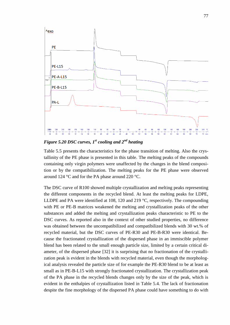
77
Figure 5.20 DSC curves, 1st cooling and 2
nd heating
Table 5.5 presents the characteristics for the phase transition of melting. Also the crys-
tallinity of the PE phase is presented in this table. The melting peaks of the compounds
containing only virgin polymers were unaffected by the changes in the blend composi-
tion or by the compatibilization. The melting peaks for the PE phase were observed
around 124 °C and for the PA phase around 220 °C.
The DSC curve of R100 showed multiple crystallization and melting peaks representing
the different components in the recycled blend. At least the melting peaks for LDPE,
LLDPE and PA were identified at 108, 120 and 219 °C, respectively. The compounding
with PE or PE-B matrices weakened the melting and crystallization peaks of the other
substances and added the melting and crystallization peaks characteristic to PE to the
DSC curves. As reported also in the context of other studied properties, no difference
was obtained between the uncompatibilized and compatibilized blends with 30 wt.% of
recycled material, but the DSC curves of PE-R30 and PE-B-R30 were identical. Be-
cause the fractionated crystallization of the dispersed phase in an immiscible polymer
blend has been related to the small enough particle size, limited by a certain critical di-
ameter, of the dispersed phase [32] it is surprising that no fractionation of the crystalli-
zation peak is evident in the blends with recycled material, even though the morpholog-
ical analysis revealed the particle size of for example the PE-R30 blend to be at least as
small as in PE-B-L15 with strongly fractionated crystallization. The crystallization peak
of the PA phase in the recycled blends changes only by the size of the peak, which is
evident in the enthalpies of crystallization listed in Table 5.4. The lack of fractionation
despite the fine morphology of the dispersed PA phase could have something to do with

78
the additives and other substances in the recycled material which could somehow hinder
the delaying of the crystallization.
Table 5.5 Melting characteristics of the compounds
Material
Tm1
[°C]
∆H1
[J/g]
Tm2
[°C]
∆H2
[J/g]
Tm3
[°C]
∆H3
[J/g]
PE Crystallinity
[%]
PE
123.7
43,9
PA-L
220.9 -81.93
PA-M
220.8 -77.17
PE-A
123.8
43.97
PE-B
123.6
43.6
PE-A-L5
123.8
219.4 -3.57 40.29
PE-A-L15
124.8
220.7 -9.93 35.94
PE-A-M5
125.2
220.7 -3.71 40.43
PE-A-M15
124.2
220.3 -9.92 36.24
PE-B-L5
124.0
219.5 -3.20 42.9
PE-B-L15
124.0
220.2 -10.6 36.21
PE-L15
123.8
220.2 -8.88 36.54
R100 108.8 -53.0 119.7 -13,7 218.3 -10.6
PE-R30 x
123.5
218.5 -3.21 37.68
PE-B-R10 x
124.3
218.4 -1.31 39.76
PE-B-R30 x
123
218 -3.70 35.69
PE-B-R50 x 122.6 218 -5.84 32.11
x= peak observed
In general, the PE and PA phases in the blends showed clear separate melting and crys-
tallization processes by having separate peaks for each phases. The blends with virgin
materials showed fractionated crystallization and the addition of CP shifted the delayed
crystallization peak to lower temperatures. The higher the CP/PA ratio was the stronger
the shift was. This shift can be taken as an indication of an effective compatibilization.
In the compounds with recycled material no fractionated crystallization was observed
despite the small particles observed in the morphological analysis. The unknown addi-
tives and other substances or the oxidised components in the recycled blend could have
affected the crystallization of the PA phase in the recycled blends.

79
6. CONCLUSIONS
Two sets of reactively compatibilized compounds with variety of blend composition
were studied. The matrix material in all compounds was a commercial Borstar® poly-
ethylene and depending on the compound 5 or 10 wt.% of maleic anhydride grafted
compatibilizer precursor, CP was added to the matrices. The minor phase in the first set
of compounds was low viscosity or medium viscosity polyamide 6 or a blend of recy-
cled packaging film material comprising at least of polyamide and polyethylene. The
effects of the blend composition and the CP content in the matrix were studied by me-
chanical tests of tensile properties and Charpy impact strength and by morphological,
melt flow rate and DSC thermal analysis. The objective of the thesis was to evaluate the
behaviour of the Borstar® polyethylene, PE as a matrix material for neat polyamide
with different viscosity and for the recycled material when the blends are reactively
compatibilized by using a maleic anhydride grafted polyethylene as CP.
The most significant finding was that the commercial PE-g-MA compatibilizer precur-
sor used in the study showed a strong compatibilizing efficiency towards the virgin
blends of PE and polyamides with low and medium viscosities. The CP did not have
any significant effects on the properties of the pure matrix material.
The mechanical properties of the compounds were good indicators of the interfacial
adhesion between the blend components as they describe the ability of the stress distri-
bution under different type of mechanical stresses and impacts. The Charpy impact
strength of 85/15 PE/PA-L blend was increased by 250 % with the addition of 5 wt.% of
CP in the matrix, and by almost 480 % with 10 wt.% of CP. The latter blend resulted in
impact strength approximately 10 % higher than those of PE or PA which demonstrates
well the toughening effect of the dispersed PA droplets in the matrix and the good adhe-
sion between the phases. The tensile moduli of the compounds were slightly affected by
the compatibilization as the addition of CP decreased the modulus. The effect was seen
also in the strain at break observed in a tensile tests for 85/15 PE/PA blend as the addi-
tion of CP in the blend increased the strain from 10 to over 400 %.
As expected, the addition of CP in the PE/PA blend affected the blend morphology by
decreasing the size of the dispersed phase droplets. This was due to the reduced interfa-
cial tension between the phases as the in-situ formed PE-g-MA compatibilizer locates to
the interfaces. The effect of the compatibilization on flow properties was observed in
the decreased MFR as the MFR of the uncompatibilized 85/15 PE/PA blend decreased
approximately 65 % when 10 wt.% of CP was added to the matrix phase. The MFR of

80
the compatibilized blend was even smaller than that of the neat PE, which indicates
strongly of the formation of grafted structures in the compatibilized blend.
The thermal analysis conducted by differential scanning calorimetry, DSC revealed
fractionated crystallization in the PA phase for blends with virgin components. The
higher the CP/PA ratio was the stronger the shift of the delayed crystallization peak to
lower temperatures was which can be taken as an indication of increasing compatibiliza-
tion efficiency.
The compatibilization efficiency of the PE-g-MA compatibilizer precursor in the blends
of PE and recycled packaging material blend showed no evidence. The differences in all
the studied properties; visual, thermal, morphological, melt flow or mechanical were
negligible between the uncompatibilized and compatibilized blends comprising of 70
wt.% of PE and 30 wt.% of recycled material.
Despite the lack of the evidence of working CP the Borstar® polyethylene demonstrated
a good behaviour as the matrix material for the recycled blend. The observed morpholo-
gy for 70/30 PE/recycled material blend showed small, evenly distributed PA droplets
in PE matrix with good adhesion between the phases. The sizes of the dispersed droplets
were approximately the same range as observed in the virgin blend with 15 wt.% of PA
and 10 wt.% of CP in the matrix. Despite the small sizes of the dispersed particles, no
fractionated crystallization was observed in the DSC scans.
When the properties of the blends with the recycled component were analysed based on
the calculated polyamide content and compared to the trends observed in the virgin
blends only in the strain at yield the recycled blend is observed to increase as the virgin
blends decrease. All the other analysed quantitative values for the recycled blends
showed the same increasing or decreasing trends as the virgin blends.
The reason for the differing behaviour of the recycled blends when compared to virgin
blends and possibly for the inefficient compatibilization with the CP is probably in the
other content of the recycled blend than the PA phase, which the experimental part was
focused on. It was analysed that the recycled blend contained at least PA, LDPE,
LLDPE and possibly some sort of an adhesive material used to tie the PE and PA layers
together in the packaging films. It is possible that this adhesive material acts as a CP
itself and thus no additional CP is needed in the blends of PE matrix and recycled multi-
layer packaging film material. Another reason for the fine morphology and the lack of
difference between the compatibilized and uncompatibilized recycled blends could be in
the oxidized substances in the recycled blend originating from the additional processing
steps the recycled blends was subjected to, indicated by the darkened colour of the recy-
cled compounds. These oxidized polar groups could also react with PA and thereby
compatibilize the blend.

81
Possible further actions to conduct would be to perform a comparative analysis in which
a different type of matrix with, for example, lower viscosity or unimodal structure is
used. Also a more detailed analysis on the content of the recycled blend would be nec-
essary to understand the reactions occurring during compounding. The identification of
the possible applications in which a blend with recycled content in it could work is im-
portant. This would give more specific frames for the research conducted and it would
help to direct the resulting properties in the right direction, if modification of the blend
composition is an option.

82
REFERENCES
[1] K. Khait, Recycling, Plastics, in: Encyclopedia of Polymer Science and Technology,
John Wiley & Sons, Inc., 2002.
[2] Plastics - the Facts 2014, in: An analysis of European plastics production, demand
and waste data, PlasticsEurope, Presentation slides, Belgium, 2015.
[3] Being wise with waste: the EU’s approach to waste management, in: European
Commission, Publications Office of the European Union, Information brochure, Lux-
embourg, 2010, pp. 1-16.
[4] J.R. Araújo, M.R. Vallim, M.A.S. Spinacé, M.-. De Paoli, Use of postconsumer pol-
yethylene in blends with polyamide 6: Effects of the extrusion method and the compati-
bilizer, Journal of Applied Polymer Science, Vol. 110, No. 3, 2008, pp. 1310-1317.
[5] Z. Horák, I. Fortelný, J. Kolařík, D. Hlavatá, A. Sikora, Polymer Blends, in: H.F.
Mark (ed.), Encyclopedia of Polymer Science and Technology, 3rd ed., John Wiley &
Sons, Inc., 2005.
[6] C. Vasile, 7. Reactive Blending, in: A.K. Kulshreshtha, C. Vasile (ed.), Handbook of
Polymer Blends and Composites, Volumes 1-4, Smithers Rapra Technology, 2002, pp.
215-274.
[7] A. Argoud, L. Trouillet-Fonti, S. Ceccia, P. Sotta, Morphologies in Polyamide
6/High Density Polyethylene blends with high amounts of reactive compatibilizer, Eu-
ropean Polymer Journal, Vol. 50, No. 0, 2014, pp. 177-189.
[8] P.L. Beltrame, A. Castelli, M.D. Pasquantonio, M. Canetti, A. Seves, Influence of
interfacial agents on the physicochemical characteristics of binary polyeth-
ylene/polyamide 6 and ternary polyethylene/polypropylene/polyamide 6 blends, Journal
of Applied Polymer Science, Vol. 60, No. 4, 1996, pp. 579-590.
[9] C. Burgstaller, C.A.P. Bigarella, B. Riedl, W. Stadlbauer, Compatibilizing Immisci-
ble Blends from Polyethylenes and Polyamide Using Reactive Extrusion, ANTEC 2014
- Proceedings of the Technical Conference & Exhibition, Las Vegas, Nevada, USA
April 28-30, 2014, 28-30.4.2014, Society of Plastics Engineers, pp. 20-24.
[10] V. Chiono, S. Filippi, H. Yordanov, L. Minkova, P. Magagnini, Reactive compati-
bilizer precursors for LDPE/PA6 blends. III: ethylene–glycidylmethacrylate copolymer,
Polymer, Vol. 44, No. 8, 2003, pp. 2423-2432.
[11] S. Filippi, L. Minkova, N. Dintcheva, P. Narducci, P. Magagnini, Comparative
study of different maleic anhydride grafted compatibilizer precursors towards
LDPE/PA6 blends: Morphology and mechanical properties, Polymer, Vol. 46, No. 19,
2005, pp. 8054-8061.

83
[12] S. Filippi, H. Yordanov, L. Minkova, G. Polacco, M. Talarico, Reactive Compati-
bilizer Precursors for LDPE/PA6 Blends, 4, Macromolecular Materials and Engineer-
ing, Vol. 289, No. 6, 2004, pp. 512-523.
[13] R. González-Nuñez, M. Arellano, F.J. Moscoso, V.M. González-Romero, B.D.
Favis, Determination of a limiting dispersed phase concentration for coalescence in
PA6/HDPE blends under extensional flow, Polymer, Vol. 42, No. 12, 2001, pp. 5485-
5489.
[14] Å Halldén, M.J. Deriss, B. Wesslén, Morphology of LDPE/PA-6 blends compati-
bilised with poly(ethylene-graft-ethylene oxide)s, Polymer, Vol. 42, No. 21, 2001, pp.
8743-8751.
[15] F. Hamid, S. Akhbar, K.H.K. Halim, Mechanical and Thermal Properties of Poly-
amide 6/HDPE-g- MAH/High Density Polyethylene, Procedia Engineering, Vol. 68,
No. 0, 2013, pp. 418-424.
[16] C. Jiang, S. Filippi, P. Magagnini, Reactive compatibilizer precursors for
LDPE/PA6 blends. II: maleic anhydride grafted polyethylenes, Polymer, Vol. 44, No. 8,
2003, pp. 2411-2422.
[17] B. Jurkowski, Y.A. Olkhov, K. Kelar, O.M. Olkhova, Thermomechanical study of
low-density polyethylene, polyamide 6 and its blends, European Polymer Journal, Vol.
38, No. 6, 2002, pp. 1229-1236.
[18] K. Kelar, B. Jurkowski, Preparation of functionalised low-density polyethylene by
reactive extrusion and its blend with polyamide 6, Polymer, Vol. 41, No. 3, 2000, pp.
1055-1062.
[19] R.A. Kudva, H. Keskkula, D.R. Paul, Morphology and mechanical properties of
compatibilized nylon 6/polyethylene blends, Polymer, Vol. 40, No. 22, 1999, pp. 6003-
6021.
[20] L. Li, B. Yin, Y. Zhou, L. Gong, M. Yang, B. Xie, C. Chen, Characterization of
PA6/EPDM-g-MA/HDPE ternary blends: The role of core-shell structure, Polymer,
Vol. 53, No. 14, 2012, pp. 3043-3051.
[21] G. Lin, G. Sui, R. Yang, Mechanical and shape-memory properties of polyam-
ide/maleated polyethylene/linear low-density polyethylene blend, Journal of Applied
Polymer Science, Vol. 126, No. 1, 2012, pp. 350-357.
[22] L. Minkova, H. Yordanov, S. Filippi, Characterization of blends of LDPE and PA6
with functionalized polyethylenes, Polymer, Vol. 43, No. 23, 2002, pp. 6195-6204.
[23] K.Y. Park, S.H. Park, K. Suh, Improved nylon 6/LDPE compatibility through
grafting of isocyanate functional group, Journal of Applied Polymer Science, Vol. 66,
No. 11, 1997, pp. 2183-2189.

84
[24] G. Serpe, J. Jarrin, F. Dawans, Morphology-processing relationships in polyeth-
ylene-polyamide blends, Polymer Engineering & Science, Vol. 30, No. 9, 1990, pp.
553-565.
[25] A. Sharif-Pakdaman, J. Morshedian, Y. Jahani, Effect of organoclay and silane
grafting of polyethylene on morphology, barrierity, and rheological properties of
HDPE/PA6 blends, Journal of Applied Polymer Science, Vol. 127, No. 2, 2013, pp.
1211-1220.
[26] C. Shen, Y. Zhou, R. Dou, W. Wang, B. Yin, M. Yang, Effect of the core-forming
polymer on phase morphology and mechanical properties of PA6/EPDM-g-MA/HDPE
ternary blends, Polymer, Vol. 56, No. 0, 2015, pp. 395-405.
[27] M.R. Vallim, J.R. Araujo, M.A.S. Spinacé, M. De Paoli, Polyamide-6/high-density
polyethylene blend using recycled high-density polyethylene as compatibilizer: Mor-
phology, mechanical properties, and thermal stability, Polymer Engineering & Science,
Vol. 49, No. 10, 2009, pp. 2005-2014.
[28] C. Vocke, U. Anttila, J. Seppälä, Compatibilization of polyethylene/polyamide 6
blends with oxazoline-functionalized polyethylene and styrene ethylene/butylene sty-
rene copolymer (SEBS), Journal of Applied Polymer Science, Vol. 72, No. 11, 1999,
pp. 1443-1450.
[29] S. Wang, C. Lin, H. Sun, F. Chen, J. Li, S. Guo, Ultrasonic characterization of
phase morphology of high density polyethylene/polyamide 6 blend melts, Polymer En-
gineering & Science, Vol. 52, No. 2, 2012, pp. 338-345.
[30] Q. Wei, D. Chionna, E. Galoppini, M. Pracella, Functionalization of LDPE by Melt
Grafting with Glycidyl Methacrylate and Reactive Blending with Polyamide-6, Macro-
molecular Chemistry and Physics, Vol. 204, No. 8, 2003, pp. 1123-1133.
[31] B. Yin, L. Li, Y. Zhou, L. Gong, M. Yang, B. Xie, Largely improved impact
toughness of PA6/EPDM-g-MA/HDPE ternary blends: The role of core–shell particles
formed in melt processing on preventing micro-crack propagation, Polymer, Vol. 54,
No. 7, 2013, pp. 1938-1947.
[32] C. Yordanov, L. Minkova, Fractionated crystallization of compatibilized
LDPE/PA6 blends, European Polymer Journal, Vol. 41, No. 3, 2005, pp. 527-534.
[33] V. Yquel, A.V. Machado, J.A. Covas, J.J. Flat, Contribution of the melting stage to
the evolution of the morphology and chemical conversion of immiscible polyam-
ide/polyethylene blends in twin-screw extruders, Journal of Applied Polymer Science,
Vol. 114, No. 3, 2009, pp. 1768-1776.
[34] S. Filippi, V. Chiono, G. Polacco, M. Paci, L.I. Minkova, P. Magagnini, Reactive
compatibilizer precursors for LDPE/PA6 blends, 1. Ethylene/acrylic acid copolymers,
Macromolecular Chemistry and Physics, Vol. 203, No. 10-11, 2002, pp. 1512-1525.

85
[35] ARVI (Material Value Chains, Materiaalien arvovirrat), CLEEN - Cluster for En-
ergy and Environment, [WWW]. Available at: (cited 27.05.2015):
http://www.cleen.fi/fi/arvi.
[36] Tukes tutkii turvallisuutta, PYR Info - Pakkausalan Ympäristörekisteri PYR Oy:n
tiedotuslehti, Iss. 1, 2015, pp. 8-9.
[37] Muovipakkaukset talteen, PYR Info - Pakkausalan Ympäristörekisteri PYR Oy:n
tiedotuslehti, Iss. 1, 2015, pp. 13-13.
[38] GREEN PAPER On a European strategy on Plastic Waste in the Environment, Eu-
ropean Commission, Green Paper, Brussels, 2013, pp. 1-20.
[39] EN 15343, Plastics - Recycled Plastics - Plastics recycling traceability and assess-
ment of conformity and recycled content, European Standard, 2007, .
[40] K. Hamad, M. Kaseem, F. Deri, Recycling of waste polymer from polymer materi-
als: An overview of the recent works, Polymer Degradation and Stability, Vol. 98, No.
12, 2013, pp. 2801-2812.
[41] Jätealan lainsäädännön kokonaisuudistus, Ympäristöministeriö, Ministry of th En-
vironment of Finland, [WWW]. Available at (cited 05.06.2015): http://www.ym.fi/fi-
fi/Ymparisto/Lainsaadanto_ja_ohjeet/Ymparistonsuojelun_valmisteilla_oleva_lainsaada
nto/Jatealan_lainsaadannon_kokonaisuudistus.
[42] Packaking and Packaking waste Directive, 94/62/EC.
[43] Registration, Evaluation, Authorization and Registration, REACH, Regulation,
1907/2006/EC.
[44] ISO 15270, Plastics - Guidelines for the recovery and recycling of plastics waste,
International Organization of Standardization, 2008.
[45] V. Arrighi, J. Cabral, J.M.G. Cowie, Miscibility, in: Encyclopedia of Polymer Sci-
ence and Technology, John Wiley & Sons, Inc., 2002.
[46] V.Y. Senichev, V.V. Tereshatov, 6. Theories of Compatibility, in: G. Wypych
(ed.), Handbook of Plasticizers, 2nd ed., ChemTec Publishing, 2012, pp. 135-164.
[47] C. Vasile, G.G. Bumbu, Thermodynamics of Multicomponent Polymer Systems,
in: A.K. Kulshreshtha, C. Vasile (ed.), Handbook of Polymer Blends and Composites,
Volume 3A, Smithers Rapra Technology, 2002, pp. 19-63.
[48] Y.-. Sun, W. Baker, 9. Compatibilization Using Low Molecular Weight Reactive
Additives, in: W. Baker, C. Scott, G.-. Hu (ed.), Reactive Polymer Blending, Hanser
Publishers, 2001, pp. 254-281.
[49] L.A. Utracki, Compatibilization of Polymer Blends, The Canadian Journal of
Chemical Engineering, Vol. 80, No. 6, 2002, pp. 1008-1016.

86
[50] N.C. Liu, H. Huang, Types of Reactive Polymers Used in Blending, in: W. Baker,
C. Scott, G.-. Hu (ed.), Reactive Polymer Blending, Hanser Publishers, 2001, pp. 14-35.
[51] C. Koning, M. Van Duin, C. Pagnoulle, R. Jerome, Strategies for compatibilization
of polymer blends, Progress in Polymer Science, Vol. 23, No. 4, 1998, pp. 707-757.
[52] A. Ajji, L.A. Utracki, Interphase and compatibilization of polymer blends, Polymer
Engineering & Science, Vol. 36, No. 12, 1996, pp. 1574-1585.
[53] H. Cartier, G. Hu, A novel reactive extrusion process for compatibilizing immisci-
ble polymer blends, Polymer, Vol. 42, No. 21, 2001, pp. 8807-8816.
[54] M. Lambla, M. Seadan, Interfacial grafting and crosslinking by free radical reac-
tions in polymer blends, Polymer Engineering & Science, Vol. 32, No. 22, 1992, pp.
1687-1694.
[55] M. Xanthos, S.S. Dagli, Compatibilization of polymer blends by reactive pro-
cessing, Polymer Engineering & Science, Vol. 31, No. 13, 1991, pp. 929-935.
[56] G. Hu, H. Cartier, C. Plummer, Reactive Extrusion: Towards Nanoblends, Macro-
molecules, Vol. 32, No. 14, 1999, pp. 4713-4718.
[57] G. Moad, The synthesis of polyolefin graft copolymers by reactive extrusion, Pro-
gress in Polymer Science, Vol. 24, No. 1, 1999, pp. 81-142.
[58] G. Hu, M. Lambla, Fundamentals of Reactive Extrusion: An Overview, in: Materi-
als Science and Technology, Wiley-VCH Verlag GmbH & Co. KGaA, 2006.
[59] J. Seppälä, Polymeeriteknologian perusteet, 5th ed. Otatieto Oy, Helsinki, Finland,
2005, 261-271 p.
[60] C. Tzoganakis, S. Zhu, Reactive Extrusion of Polymers, in: Encyclopedia of Poly-
mer Science and Technology, John Wiley & Sons, Inc., 2002.
[61] G. Hu, 6. Reactive Blending in Screw Extruders, in: W. Baker, C. Scott, G.-. Hu
(ed.), Reactive Polymer Blending, Hanser Publishers, 2001, pp. 143-178.
[62] H.K. Jeon, C.W. Macosko, B. Moon, T.R. Hoye, Z. Yin, Coupling Reactions of
End- vs Mid-Functional Polymers, Macromolecules, Vol. 37, No. 7, 2004, pp. 2563-
2571.
[63] C.W. Macosko, H.K. Jeon, T.R. Hoye, Reactions at polymer–polymer interfaces
for blend compatibilization, Progress in Polymer Science, Vol. 30, No. 8–9, 2005, pp.
939-947.
[64] T.C. Chung, Synthesis of functional polyolefin copolymers with graft and block
structures, Progress in Polymer Science, Vol. 27, No. 1, 2002, pp. 39-85.

87
[65] E. Passaglia, S. Coiai, S. Augier, Control of macromolecular architecture during
the reactive functionalization in the melt of olefin polymers, Progress in Polymer Sci-
ence, Vol. 34, No. 9, 2009, pp. 911-947.
[66] M.J. Yanjarappa, S. Sivaram, Recent developments in the synthesis of functional
poly(olefin)s, Progress in Polymer Science, Vol. 27, No. 7, 2002, pp. 1347-1398.
[67] R. Jerome, C. Pagnoulle, 4. Key Role of Structural Features of Compatibilizing
Polymer Additives in Reactive Blending, in: W. Baker, C. Scott, G.-. Hu (ed.), Reactive
Polymer Blending, Hanser Publishers, 2001, pp. 82-112.
[68] J.K. Fink, 16. Compatibilization, in: Reactive Polymers Fundamentals and Appli-
cations - A Concise Guide to Industrial Polymers (2nd Edition), 2nd ed., Elsevier, 2013,
pp. 373-409.
[69] U. Anttila, C. Vocke, J. Seppälä, Functionalization of polyolefins and elastomers
with an oxazoline compound, Journal of Applied Polymer Science, Vol. 72, No. 7,
1999, pp. 877-885.
[70] C. Chuai, M. Iqbal, S. Tian, A study on melt grafting of maleic anhydride onto
low-density polyethylene and its blend with polyamide 6, Journal of Polymer Science
Part B: Polymer Physics, Vol. 48, No. 3, 2010, pp. 267-275.
[71] W. Heinen, C.H. Rosenmöller, C.B. Wenzel, H.J.M. de Groot, L. Lugtenburg, M.
van Duin, 13
C NMR Study of the Grafting of Maleic Anhydride onto Polyethene, Poly-
propene, and Ethene-Propene Copolymers, Macromolecules, Vol. 29, No. 4, 1996, pp.
1151-1157.
[72] S. Ranganathan, W.E. Baker, K.E. Russell, R.A. Whitney, Peroxide-initiated graft-
ing of maleic anhydride onto linear and branched hydrocarbons, Journal of Polymer
Science Part A: Polymer Chemistry, Vol. 37, No. 20, 1999, pp. 3817-3825.
[73] C.A. Orr, J.J. Cernohous, P. Guegan, A. Hirao, H.K. Jeon, C.W. Macosko, Homo-
geneous reactive coupling of terminally functional polymers, Polymer, Vol. 42, No. 19,
2001, pp. 8171-8178.
[74] A. Naranjo, M.d.P. Noriega, T.A. Osswald, A. Roldán-Alzate, J.D. Sierra, Plastics
Testing and Characterisation - Industrial Applications, 1st ed. Hanser Publishers, Mu-
nich, 2008, 7-53 p.
[75] G.E. Molau, Heterogeneous polymer systems. II. Mechanism of stabilization of
polymeric oil-in-oil emulsions, Journal of Polymer Science Part A: General Papers, Vol.
3, No. 12, 1965, pp. 4235-4242.
[76] U. Anttila, K. Hakala, T. Helaja, B. Löfgren, J. Seppälä, Compatibilization of poly-
ethylene/polyamide 6 blends with functionalized polyethylenes prepared with metallo-
cene catalyst, Journal of Polymer Science Part A: Polymer Chemistry, Vol. 37, No. 16,
1999, pp. 3099-3108.

88
[77] M.S. Sánchez, V. Mathot, G.V. Poel, G. Groeninckx, W. Bruls, Crystallization of
polyamide confined in sub-micrometer droplets dispersed in a molten polyethylene ma-
trix, Journal of Polymer Science Part B: Polymer Physics, Vol. 44, No. 5, 2006, pp.
815-825.
[78] G. Groeninckx, C. Harrats, S. Thomas, Reactive Blending with Immiscible Func-
tional Polymers: Molecular, Morphological, and Interfacial Aspects, in: W. Baker, C.
Scott, G.-. Hu (ed.), Reactive Polymer Blending, Hanser Publishers, 2001, pp. 43-81.
[79] O.T. Ikkala, R.M. Holsti-Miettinen, J. Seppälä, Effects of compatibilization on
fractionated crystallization of PA6/PP blends, Journal of Applied Polymer Science, Vol.
49, No. 7, 1993, pp. 1165-1174.
[80] Y.X. Pang, D.M. Jia, H.J. Hu, D.J. Hourston, M. Song, A quantitative estimation of
the extent of compatibilization in heterogeneous polymer blends using their heat capaci-
ty increment at the glass transition, Journal of Applied Polymer Science, Vol. 74, No.
12, 1999, pp. 2868-2876.
[81] N.P. Cheremisinoff, Polymer Characterization - Laboratory Techniques and Analy-
sis, William Andrew Publishing/Noyes, 1996.
[82] E. Benham, M. McDaniel, Ethylene Polymers, HDPE, in: Encyclopedia of Polymer
Science and Technology, John Wiley & Sons, Inc., 2002.
[83] N. Maraschin, Ethylene Polymers, LDPE, in: Encyclopedia of Polymer Science
and Technology, John Wiley & Sons, Inc., 2002, .
[84] D.M. Simpson, G.A. Vaughan, Ethylene Polymers, LLDPE, in: Encyclopedia of
Polymer Science and Technology, John Wiley & Sons, Inc., 2002.
[85] H. Shen, B. Xie, W. Yang, M. Yang, Thermal and rheological properties of poly-
ethylene blends with bimodal molecular weight distribution, Journal of Applied Poly-
mer Science, Vol. 129, No. 4, 2013, pp. 2145-2151.
[86] B. Herzog, M.I. Kohan, S.A. Mestemacher, R.U. Pagilagan, K. Redmond, Polyam-
ides, in: Ullmann's Encyclopedia of Industrial Chemistry, Wiley-VCH Verlag GmbH &
Co. KGaA, 2000.
[87] R.J. Palmer, Polyamides, Plastics, in: Encyclopedia of Polymer Science and Tech-
nology, 3rd. ed., John Wiley & Sons, Inc., 2002, pp. 618-643.
[88] File:PA6-PA66.png, Wikimedia Commons, [WWW]. Available at (cited
05.04.2015): http://commons.wikimedia.org/wiki/File:PA6-PA66.png.
[89] Polyamides (PA) - High Increase in Consumption, Vol. 2004, Iss. 10, 2004, pp. 95-
100.
[90] A. Valenza, A.M. Visco, D. Acierno, Characterization of blends with polyamide 6
and ethylene acrylic acid copolymers at different acrylic acid content, Polymer Testing,
Vol. 21, No. 1, 2002, pp. 101-109.

89
[91] C. Vocke, U. Anttila, M. Heino, P. Hietaoja, J. Seppälä, Use of oxazoline function-
alized polyolefins and elastomers as compatibilizers for thermoplastic blends, Journal of
Applied Polymer Science, Vol. 70, No. 10, 1998, pp. 1923-1930.
[92] M. Pracella, L. Rolla, D. Chionna, A. Galeski, Compatibilization and properties of
poly(ethylene terephthalate)/polyethylene blends based on recycled materials, Macro-
molecular Chemistry and Physics, Vol. 203, No. 10-11, 2002, pp. 1473-1485.
[93] M. Jaziri, N. Barhoumi, V. Massardier, F. Mélis, Blending PP with PA6 industrial
wastes: Effect of the composition and the compatibilization, Journal of Applied Poly-
mer Science, Vol. 107, No. 6, 2008, pp. 3451-3458.
[94] C. Desiderá, M.I. Felisberti, PA-66/PEA1 Blends from recycled waste, Feedsctoc
Recycling of Plastics - Selected Papers presented at the Third International Symposium
on Feedstock recycling of Plastics, 25.-29.9.2005, Universitätsverlag Karlsruhe, pp.
495-501.
[95] S.M. Hong, S.S. Hwang, J.S. Choi, H.J. Choi, Compatibility effect of reactive co-
polymers on polypropylene/polyamide 6 blends from commingled plastic wastes, Jour-
nal of Applied Polymer Science, Vol. 101, No. 2, 2006, pp. 1188-1193.
[96] A. Choudhury, M. Mukherjee, B. Adhikari, Recycling of polyethylene/nylon 6
based waste oil pouches using compatibilizer, Indian Journal of Chemical Technology,
Vol. 13, No. 3, 2006, pp. 233-241.
[97] M. van Duin, R.J.M. Borggreve, Blends of polyamides and maleic-anhydride-
containing polymers: interfacial chemistry and properties, in: S. Al-Malalaika (ed.),
Reactive modifiers for Polymers, Springer Netherlands, 1997, pp. 133-162.
[98] P. Maréchal, G. Coppens, R. Legras, J. Dekoninck, Amine/anhydride reaction ver-
sus amide/anhydride reaction in polyamide/anhydride carriers, Journal of Polymer Sci-
ence Part A: Polymer Chemistry, Vol. 33, No. 5, 1995, pp. 757-766.
[99] T.D. Jones, J.S. Schulze, C.W. Macosko, T.P. Lodge, Effect of Thermodynamic
Interactions on Reactions at Polyme/Polymer Interfaces, Macromolecules, Vol. 36, No.
19, 2003, pp. 7212-7219.
[100] SFS-EN ISO 179-1, Plastics. Determination of Charpy impact properties. Part 1:
Non-instrumented impact test, Finnish Standards Association, Helsinki, 2010, 26 p.
[101] SFS-EN ISO 527-1, Plastics – Determination of tensile properties – Part 1: Gen-
eral principles, Finnish Standards Association, Helsinki, 2012, 26 p.
[102] SFS-EN ISO 1133-1, Plastics. Determination of the melt mass-flow rate (MFR)
and melt volume-flow rate (MVR) of thermoplastics. Part 1: Standard method, Finnish
Standards Association, Helsinki, 2012, 28 p.
[103] SFS-EN ISO 11357-1, Plastics. Differential scanning calorimetry (DSC). Part 1:
General principles, Finnish Standards Association, Helsinki, 2009, 35 p.

90
APPENDIX A: COMPOUNDING PARAMETERS
Compound
Screw
speed
[rpm]
T melt
[°C]
P melt
[bar]
Torque
[%]
Productivi-
ty [kg/h]
Matrix blends PE-A 200 206 27-29 89-92 9
PE-B 200 207 27-29 84-86 9
Experimental blends PE-L15 200 263 10 56-57 9
PE-A-L5 200 246 20-21 69-71 9
PE-A-L15 200 245 19-20 64-66 9
PE-A-M5 200 244 17-19 70-72 9
PE-A-M15 200 245 13-14 54-55 7
PE-B-L5 200 243 16 62-63 8
PE-B-L15 200 243 16-17 63-65 8
Recycled blends R100 200 241 2 43 2.5-3
PE-R30 150 243 5-7 53-55 5
PE-B-R10 150 244 8-9 54-55 5
PE-B-R30 150 243 6-7 49-50 5
PE-B-R50 150 243 4 42-43 5

91
APPENDIX B: COMPARISON OF THE TENSILE PROPERTIES
OF THE COMPOUNDS WITH PA-L AND PA-M
Figure 6.1 Tensile properties of the compounds containing 5 wt.% of CP and low vis-
cosity PA or medium viscosity PA (a) Tensile Modulus, (b) Tensile Strength, (c) Stress
at Yield, (d) Strain at yield and (e) Strain at Break
350 428
504
350 415
513
0
100
200
300
400
500
600
no PA 5 % of PA 15 % of PA
Ten
sile
Mo
du
lus
[MP
a]
23,8 20,1
15,3
23,8 22,2
13,3
0
5
10
15
20
25
30
no PA 5 % of PA 15 % of PA
Ten
sile
Str
en
gth
[M
Pa]
11,4
12,2
13,3
11,4 12,1
13,3
10
11
12
13
14
no PA 5 % of PA 15 % of PA
Stre
ss a
t Y
ield
[M
Pa]
14
11 10,6
14
11 10
0
5
10
15
no PA 5 % of PA 15 % of PA
Stra
in a
t Y
ield
[%
]
800
590
412
800 710
270
0
200
400
600
800
1000
no PA 5 % of PA 15 % of PA
Stra
in a
t B
reak
[%
]
Low viscosity PA
Medium viscosity PA
a) b)
c) d)
e)

92
APPENDIX C: SEM MICROGRAPHS OF DISPERSED FIBROUS
POLYAMIDE DROPLETS
Figure 6.2 PE-L15
Figure 6.3 PE-A-L15

93
Figure 6.4 PE-B-L15
Figure 6.5 PE-B-R30