low grade waste heat recovery - homepages at wmu
TRANSCRIPT

Low Grade Waste Heat RecoveryProfessor HoSung Lee
10/3/2018
Mechanical and Aerospace Engineering
Western Michigan University
1
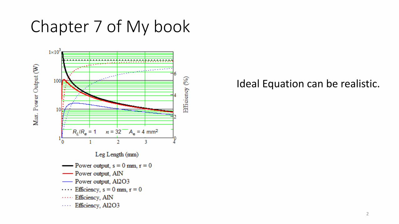
Chapter 7 of My book
Ideal Equation can be realistic.
2

Models
• Working fluid is ethylene glycol (Otherwise the same as Chapter 7)
• With and without aluminum block
• With or without Heat Sinks (Junction temperature = fluid inlet)
3

Two Flow System for Thermoelectric Generator
Ws
Ls
bs
tszs
4

Inputs for Modeling
• High fluid inlet temperature of 120 C
• Low fluid inlet temperature of 25 C
• Both volume flow rates of 1 gpm
• Thermoelectric module TE-127-1.0-2.5 (Ae = 1mm^2, L = 2.5 mm)
5

Mathcad Results
TEG RL Th.i Vol Ae le 3.701 %
TEG RL Th.i Vol Ae le Pout RL Th.i Vol Ae le Qh RL Th.i Vol Ae le
I RL Th.i Vol Ae le Qh RL Th.i Vol Ae le Qc RL Th.i Vol Ae le Th RL Th.i Vol Ae le
Tc RL Th.i Vol Ae le
Th.o RL Th.i Vol Ae le Tc.o RL Th.i Vol Ae le
Find I Qh Qc Th Tc Th.o Tc.o
6

With Aluminum Block Without Aluminum Block
0 1 2 3
40
60
80
100
120
Load Resistance Ratio
Jun
ctio
n T
emp
erat
ure
(°C
)
Hot Junction
Cold Junction
0 1 2 3
40
60
80
100
120
Load Resistance Ratio
Jun
ctio
n T
emp
erat
ure
(°C
)
Hot Junction
Cold Junction
0 0.5 1 1.5 2 2.5 30
0.2
0.4
0.6
0.8
1
0
1
2
3
4
5
Power outout
Efficiency
Load Resistance Ratio
Ou
tpu
t P
ow
er (
W)
Eff
icie
ncy
(%
)
0 0.5 1 1.5 2 2.5 30
0.2
0.4
0.6
0.8
0
1
2
3
4
5
Power outout
Efficiency
Load Resistance Ratio
Ou
tpu
t P
ow
er (
W)
Eff
icie
ncy
(%
)
7

With Aluminum Block Without Aluminum Block
0 50 100 150 2000
1
2
3
0
1
2
3
Matched Output Power
Max. Possible Output Power
High Temperature Inlet (C)
Mat
ched
Outp
ut
Pow
er (
W)
Max
imum
Poss
ible
Outp
ut
Pow
er (
W)
0 50 100 150 2000
2
4
6
8
0
2
4
6
8
Max. Efficiency
Max. possible Efficiency
HighTemperature Inlet (C)
Max
imu
m E
ffic
ien
cy (
%)
Max
imu
m P
oss
ible
E
ffic
ien
cy (
%)
0 50 100 150 2000
1
2
3
0
1
2
3
Matched Output Power
Max. Possible Output Power
High Temperature Inlet (C)
Mat
ched
Outp
ut
Pow
er (
W)
Max
imum
Poss
ible
Outp
ut
Pow
er (
W)
0 50 100 150 2000
2
4
6
8
0
2
4
6
8
Max. Efficiency
Max. possible Efficiency
HighTemperature Inlet (C)M
axim
um
Eff
icie
ncy
(%
)
Max
imu
m P
oss
ible
E
ffic
ien
cy (
%)
8

With Aluminum Block Without Aluminum Block
0 0.5 1 1.5 20
0.2
0.4
0.6
0.8
0
1
2
3
4
5
Matched Output Power
Maximum Efficiency
Volume Flow Rate (gpm)
Mat
ched
Ou
tpu
t P
ow
er (
W)
Max
imu
m E
ffic
ien
cy (
%)
0 1 2 3 4 50
1
2
3
0
1
2
Matched Output Power
Max. Possible Output Power
Leg length (mm)
Mat
ched
Outp
ut
Pow
er (
W)
Max
imum
Poss
ible
Outp
ut
Pow
er (
W)
0 0.5 1 1.5 20
0.2
0.4
0.6
0.8
0
1
2
3
4
Matched Output Power
Maximum Efficiency
Volume Flow Rate (gpm)
Mat
ched
Ou
tpu
t P
ow
er (
W)
Max
imu
m E
ffic
ien
cy (
%)
0 1 2 3 4 50
1
2
3
0
1
2
Matched Output Power
Max. Possible Output Power
Leg length (mm)M
atch
ed O
utp
ut
Pow
er (
W)
Max
imum
Poss
ible
Outp
ut
Pow
er (
W)
9
0 0.5 1 1.5 20
0.2
0.4
0.6
0.8
0
1
2
3
4
5
Matched Output Power
Maximum Efficiency
Volume Flow Rate (gpm)
Mat
ched
Ou
tpu
t P
ow
er (
W)
Max
imu
m E
ffic
ien
cy (
%)
0 0.5 1 1.5 20
0.2
0.4
0.6
0.8
0
1
2
3
4
Matched Output Power
Maximum Efficiency
Volume Flow Rate (gpm)
Mat
ched
Ou
tpu
t P
ow
er (
W)
Max
imu
m E
ffic
ien
cy (
%)

With Aluminum Block Without Aluminum Block
0 1 2 3 4 50
1
2
3
0
1
2
Matched Output Power
Max. Possible Output Power
Leg length (mm)
Mat
ched
Outp
ut
Pow
er (
W)
Max
imum
Poss
ible
Outp
ut
Pow
er (
W)
0 1 2 3 4 50
1
2
3
0
1
2
Matched Output Power
Max. Possible Output Power
Leg length (mm)
Mat
ched
Ou
tpu
t P
ow
er (
W)
Max
imu
m P
oss
ible
Ou
tpu
t P
ow
er (
W)
0 1 2 3 4 50
2
4
6
8
0
2
4
6
8
Max. Efficiency
Max. possible Efficiency
Leg length (mm)
Max
imu
m E
ffic
ien
cy (
%)
Max
imu
m P
oss
ible
E
ffic
ien
cy (
%)
0 1 2 3 4 50
2
4
6
8
0
2
4
6
8
Max. Efficiency
Max. possible Efficiency
Leg length (mm)M
axim
um
Eff
icie
ncy
(%
)
Max
imum
Poss
ible
E
ffic
iency
(%
)
10

With Aluminum Block Without Aluminum Block
0 0.5 1 1.5 20
1
2
3
4
0
1
2
3
4
Matched Output Power
Maximum Efficiency
Volume Flow Rate (gpm)
Mat
ched
Ou
tpu
t P
ow
er (
W)
Max
imu
m E
ffic
ien
cy (
%)
le 0.5mm=
0 0.5 1 1.5 20
1
2
3
4
0
1
2
3
4
Matched Output Power
Maximum Efficiency
Volume Flow Rate (gpm)
Mat
ched
Ou
tpu
t P
ow
er (
W)
Max
imu
m E
ffic
ien
cy (
%)
le 0.5mm=
110 0.5 1 1.5 2
0
0.2
0.4
0.6
0.8
0
1
2
3
4
5
Matched Output Power
Maximum Efficiency
Volume Flow Rate (gpm)
Mat
ched
Ou
tpu
t P
ow
er (
W)
Max
imu
m E
ffic
ien
cy (
%)
0 0.5 1 1.5 20
0.2
0.4
0.6
0.8
0
1
2
3
4
Matched Output Power
Maximum Efficiency
Volume Flow Rate (gpm)
Mat
ched
Ou
tpu
t P
ow
er (
W)
Max
imu
m E
ffic
ien
cy (
%)

OTEC (Ocean Thermal Energy Conversion)
Bi-Te element size: 10 x 1.5 mm.Total number of n-p couples: 10,000 couples/Number of TEG modules: 500 modules.
12

Kusatsu Hot-springs TEG System
13

Waste Heat Recovery
• Geothermal Energy
14

15
Table 1. Summary for three specific waste heat recovery cases.
Performance of TEG Heat Recovery Units
(Performance for maximum power output)
Waste heat sources Hot Water 80 °C
Cold Water 25 °C
Hot Water 80 °C
Cold Water 25 °C
Hot oil and water
mixture 200 °C
Cold water 25 °C
Thermoelectric material
used
Bismuth telluride
nanocomposites
ZT = 1.4 at 80 °C
(Poudel, Hao et al. 2008)
Bismuth telluride
Bulk
ZT = 1.0 at 80 °C
(Poudel, Hao et al.
2008)
Bismuth telluride
nanocomposites
ZT = 1.1 at 200 °C
(Poudel, Hao et al.
2008)
Optimal calculations for one module
Power output (W)
per module base area 25
cm^2
~ 5 W (6.5 W) ~ 3.5 W (4.8 W) ~ 35 W
Total heat delivered (W)
~ 200 W ~ 194 W ~700 W
Conversion efficiency
(%)
~ 2.5 % (1.7 %) ~ 1.8 % (1.3 %) ~ 5 %
Ideal efficiency* /Carnot
efficiency (%)
3.4 % / 15.5 % 2.5 % / 15.5 % 6.6 % / 31 %
Estimate cost $ per
watt**
~ $2/W ~ $3/W < $1/W
Element length (mm)
0.5 mm 0.6 mm 0.3 mm
Calculations for 1000 kW power output
Total # of modules
(= 1000 kW / module
power output)
200,000 286,000 28,000
Volume of total arrays
(= Volume of array × #
of array)
10 m^3 15 m^3 1.5 m^3
Power density
(= 1000 kW / volume of
total arrays)
100 kW/m^3 70 kW/m^3 700 kW/m^3
Total hot water flow rate
(kg/s) based on water
velocity (m/s) in channel
~ 230 kg/s
0.5 m/s
~ 230 kg/s
0.5 m/s
~ 215 kg/s
0.5 m/s
Power generation (kW)
1000 kW 1000 kW 1,000 kW
Total waste heat (kW)
40,000 kW 56,000 kW 20,000 kW
Pump power (kW) for
hot & cold water flows
80 kW 80 kW 80 kW
Power generation
efficiency (%)
(1,000kW-80kW) /
40,000kW = 2.3 %
(1,000kW-80kW) /
56,000 kW = 1.6 %
(1,000kW-80kW) /
20,000 kW = 4.6 %
Payback (years) with
electricity price $0.1/kW
and operating time at
7000 hours/year
~ 3 years
=(1000kW*$2/W) /
[(1000kW-80kW)
×7000hr×$0.1/kWh]
~ 4.5 years
=(1000kW*$3/W) /
[(1000kW-80kW)
×7000hr×$0.1/kWh]
< 1.5 years
=(1000kW*$1/W) /
[(1000kW-80kW)
×7000hr×$0.1/kWh]

The End
16