low voltage power circuitbreakers · 6.3 breaker mechanism adjustments 26 6.3.1 trip latch 26 ......
TRANSCRIPT
•GEK-64460A Maintenance Manual
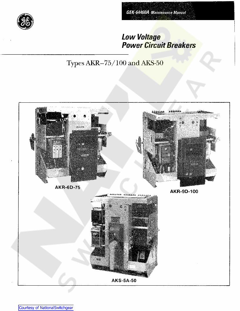
Low VoltagePower Circuit Breakers
Types AKR-75/100 and AKS-50
AKR-6D-75AKR-9D-100
AKS-5A-50

Low-Voltage Power Circuit Breakers
Table of Contents
Description Page Description Page
SECTION 1-lntroduction 4
1.1 Inspection and Maintenance 41.2 Renewal Parts ...........•.................... 4
SECTION 2-General Description 62.1 Frame Size 62.2 Operation 62.3 Mounting 72.4 Trip Device 72.5 Short Circuit Ratings 7
SECTION 3-8torage, Safety andMaintenance 9
3.1 Storage 93.2 Safety 93.3 Maintenance 9
SECTION 4-Breaker Operation 104.1 Manual Closing 104.2 Electrical Closing 104.2.1 Alternate Control Circuit 114.3 Connections 124.3.1 Stationary Breaker 124.3.2 Drawout Breaker " 124.4 Tripping 134.5 Charging and Closing Using
the Maintenance Handle 13
SECTION 5-Contact Maintenance 145.1 Slow Closing the Breaker " 145.1.1 Electrical Breaker 145.1.2 Manual Breaker 145.2 Arc Ouencher Removal and Inspection 155.2.1 Removal and Replacement 155.3 Separation of Front and Back Frames 165.4 Back Frame Assembly 185.5 Measuring Contact Force 195.5.1 Stationary Arcing Contacts 195.5.2 Stationary Main and Intermediate Contacts 195.6 Measuring Contact Wipe 195.7 Adjusting Contact Wipe 195.8 Measuring Contact Open Gap 215.9 Checking Contact Sequence 225.10 Replacement of Contacts 225.10.1 Stationary Arcing Contacts 225.10.2 Movable Arcing Contacts 225.10.3 Movable Main and Intermediate Contacts 235.10.4 Stationary Intermediate and Main Contacts 245.11 Assembly and Adjustment of Crossbar 25
© 1993 GEN ERAL ELECTRIC COMPANY
2
SECTION 6-Breaker Maintenance 266.1 Safety Precautions 266.2 Lubrication , 266.3 Breaker Mechanism Adjustments 266.3.1 Trip Latch 266.3.2 Latch Buffer 266.3.3 Reset Latch Bearing and Prop 266.4 Electrical Mechanism , 286.4.1 Control Components 286.4.2 Charging Motor 296.4.3 Motor Operator Unit 306.4.4 Spring Discharge Interlock 326.5 Manual Mechanism 326.5.1 Mechanism Part Replacement 336.5.2 Ratchet Pawl Replacement 356.5.3 Adjustments 356.6 Drawout Mechanism 366.7 Drawout Mechanism Lock 36
SECTION 7-Accessories 377.1 Primary Disconnects 377.1.1 AKR 75/100 377.1.2 AKSIAKST 50 387.2 Secondary Disconnects 397.2.1 Replacement 397.3 Auxiliary Switch 407.3.1 Replacement 407.3.2 Adjustments 407.4 Shunt Trip 417.4.1 Replacement 417.4.2 Adjustment 417.5 Undervoltage Device 427.5.1 Replacement 427.5.2 Adjustment 427.6 Static Time-Delay Undervoltage 437.7 Electric Lockout Device 447.7.1 AdJustment 447.8 Bell Alarm Device 457.8.1 Adjustment 457.9 Open Fuse Lockout Device 467.9.1 Coil Replacement 467.9.2 Adjustments 46
SECTION 8-Type SST OvercurrentT' D .np evlce 47
8.1 Programmer Unit 478.2 Current Sensors 488.2.1 Replacement of Current Sensors
- AKS 50 508.2.2 Replacement of Current Sensors
- AKR 75/100 518.3 Flux Shift Trip Device 518.4 Troubleshooting 548.4.1 SST Test Set 54

Insert to document GEK-64459D and GEK-64460A
Breaker operation
This is an insert to the maintenance manuals forAKR 30/50 (GEK 64459D) and AKR 75/100(GEK64460A). The insert describes the operation of thebreaker with the newly introduced electronic closingsystem.
For the AKR 30/50 insert to section 5 starting onpage 11.
For the AKR 75/100 insert to section 4 starting onpage 10
Replacement Parts
Replacement printed circuit board assembly for 48VDC applications: #10060126G1
Replacement printed circuit board assembly for allother voltage applications: #10060126G2
2/10/97
E.2 ELECTRICAL CLOSING
On electrically operated breakers the closingsprings are charged by a gear motor. With the springsdischarged, voltage applied to the control circuit willenergize the motor through the "G" switch contacts - seeFig. E1. The motor, through the gear reduction outputcrank, compresses the closing spring until they are fullycharged. As this fUlly charged position is reached,mechanically operated switches "F" and "G" reverse theirshown position, the "G" switch deenergizing the motorand the "F" switch establishing a circuit to the One-Shotelectronic.
With the closing spring propped fUlly-charged, thebreaker is ready for closing. This may be accomplishedelectrically by depressing the closing switch "PB" on thebreaker (if so equipped) or by a remote closing switch.Operation of the closing switch energizes the One-Shotelectronic, witch in turn energizes the closing solenoid"CC". This removes the prop, releasing the closingsprings to close the breaker.
As the One-Shot electronic is energized through aclosing contact, the "X" relay is energized as well. The"X" relay will latch in and therefore prevent a secondclosing operation on the breaker in the event it is trippedopen automatically. The closing signal must be releasedand reapplied before a second closing operation canoccur.
The closing springs on the electrically operated breakerscan be manually charged.
(X)(+)
(Y)(-)
FIG.E1 - ELEMENTARY DIAGRAM FORELECTRICALLY OPERATED DRAWOUT BREAKER.CONTACT POSITIONS ARE SHOWN WITH BREAKEROPEN AND CLOSING SPRINGS DISCHARGED. TYP #183L712 &# 568B736 "E" SERIES
CCF
G
LMPB
XOS
LEGEND
CLOSING SOLENOIDCUTOFF SWITCH, CLOSED WHENCLOSING SPRING IS FULLYCHARGED.CUTOFF SWITCH. OPEN WHENCLOSING SPRING IS FULLYCHARGED.AUXILIARY SWITCHCHARGING MOTORCLOSE PUSH-BUTTON ON BREAKERESCUTCHEON, OPTIONAL.CONTROL RELAYONE-SHOT ELECTRONIC. PULSESTHE CLOSING SOLENOID FOR250 MSEC.

FIG. 13 - MANUAL OPERATION OF CLOSING SOLENOID
Table of Contents
Description Page Description Page
106
10.110.1.110.1.210.210.2.110.2.210.310.3.1
13.113.1.113.1.213.1.313.1.4
13.213.313.4
3
13.4.213.4.313.513.5.113.5.213.5.313.5.413.613.713.7.113.7.213.813.9
SECTION 14- Electrical Characteristics ... 95
Table 23Charging and Closing Operating Currents 95Table 24
Bell Alarm Contact-Rating 95Table 25Auxiliary Switch Contact Sequence 95Table 26Auxiliary Switch Contact Ratings 95Table 27Charging Times 95Table 28Shunt Trip and Undervoltage Device 96Table 29Coil Resistance 96Table 30Instantaneous Undervoltage Device Settings 97Table 31Time-Delay Undervoltage Device Settings 97
SECTION 13-Type ECOvercurrentTrip Device 85
Direct Acting Tripping Device EC-1 B 87Long Time Delay Tripping 87Short Time Delay Tripping 87Instantaneous Tripping - High Set 87Instantaneous Tripping - Low Set , 87Replacement ,.......................... 87Adjustments 88Series Overcurrent TrippingDevice EC·2A , .. , . . . . . . . . . . . . . . . . .. 89
13.4.1 Long Time-Delay and High SetInstantaneous Tripping , 89'Instantaneous Low Set Tripping , 89Instantaneous High Set Tripping 89Series Overcurrent Tripping Device EC-1 91Short Time-Delay Tripping 91Long Time-Delay Tripping 91Instantaneous Tripping 92EC-1 Adjustment 92Positive Trip Adjustment 92Reverse Current Tripping Device 93Adjustments 94Replacements 94Switchette Feature , 94Trip Device Replacement ., 94
THESE INSTRUCTIONS ARE INTENDED FOR USE BY QUALIFIEDPERSONNEL FOR INSTRUCTION AND MAINTENANCE PURPOSES.REPRODUCTION IN WHOLE OR IN PART IS NOT PERMITTEDWITHOUT THE EXPRESS PERMISSION OF GENERAL ELECTRIC.
SECTION 9-Type ECSOvercurrentTrip Device " " 58
9.1 ECS Cabling Diagram 59
SECTION 10-MicroVersaTrip™
OvercurrentTrip Device , 60
Programmer Unit , 60Fault Trip Indicators 60Remote Fault Indication , 60MicroVersaTripTM Installation , 62AKS 50 Installation , 62AKR 50/100 Installation , 63Current Sensors 64Replacement of Currenl Sensors- AKS 50 65
10.3.2 Replacement of Curent Sensors
- AKR 75/100 6510.4 Flux Shift Trip Device 6510.5 Troubleshooting 6510.5.1 Resistance Values , 6610.5.2 False Tripping-Breakers
Equipped With Ground Fault 67MicroVersaTripTM Cabling Diagrams. . . . . . . . . . .. 67
8.4.2 Resistance Values , 558.4.3 False Tripping - Breakers
Equipped with Ground Fault , 558.5 SST Cabling Diagrams 55
SECTION 11-RMS-9/EpicMicroVersaTrip® 71
11.1 Programmer Unit 7111.1.1 Fault Trip Indicators 7111.2 RMS-9 & Epic MicroVersaTrip Installation 7111.3 Current Sensors ' 7211.3.1 Replacement of Current Sensors 7511.4 Flux Shifter Trip Device 7511.5 Troubleshooting 7511.5.1 Resistance Values 7511.5.2 False Tripping-Breakers Equipped
With Ground Fault , 7611.6 Cabling Diagrams 76
SECTION 12-MicroVersaTrip N Plus andMicroVersaTrip PM Trip Units . .. 79
12.1 Trip Unit " 7912.2 Read This First 8012.3 Product Structure 8012.4 Trip Unit Removal and Replacement 8112.5 Phase Current Sensors 8212.6 Neutral Current Sensors ' 8312.7 Rating Plug Removal and Replacement , 8312.8 Trip Unit Functions 8312.9 Trouble-Shooting Guide 84

SECTION 1-1ntroduction
IntroductionThese instructions provide the maintenance proceduresand describe the operation of the 1600 thru 4000 amp AC,6000 amp DC frame size type AKR, AKS low voltage powercircuit breakers listed in Table 1 and Table 2.
The proper use, care and maintenance of these breakers isa prime safety consideration for the protection ofpersonnel, as well as a means of minimizing equipmentdamage when faults occur, Persons who apply, use, andservice these breakers will acquire the knowledge theyneed by gaining the information contained in theseinstructions,
1.1-lnspection and MaintenanceBreakers should be cared for under a systematicmaintenance program. Taking each breaker out of serviceperiodically for inspection and maintenance is an excellentmeans of establishing high service reliability. It is goodpolicy to have one or more spare breakers to install inplace of breakers requiring maintenance. Keeping a stockof recommended renewal parts will insure thatmaintenance work can be done quickly.
How frequently an individual breaker should be inspectedwill depend on the circumstances of its use. It would bewell to inspect any breaker at least once a year. If it isfrequently operated, or installed in an area of highhumidity or a dusty, dirty atmosphere, inspections shouldbe more often. Inspections might be monthly underadverse conditions,
Table 1-AKS 50 Designations
A basic maintenance inspection should consist of anoverall visual check, plus observation of a few closing andopening operations. If a breaker is seldom operated suchthat it remains open or closed for a period of six months ormore, it is recommended that arrangements be made toopen and close it several times in succession.
Dirt, grease or other foreign material on any parts of thebreaker should be removed by a thorough and carefulcleaning, Insulating surfaces should be checked forconditions that could degrade insulating properties.
During an inspection, the breaker's contacts should beslow-closed manually (with closing springs restrained bythe safety pin) to observe contact alignment and to insurethat all mechanism parts move freely, A complete contactinspection, including measurement of wipe and force,should also be done.
To properly inspect contacts, the arc quenchers must beremoved. At this time thoroughly inspect the insidesurfaces of the arc quencher side plates and innercomponents,
1.2-Renewal PartsThe AKR breakers contain a variety of parts andassemblies, Many of these parts and assemblies areavailable as replacement parts when the need arises, Seepublication GEF4552, Renewal parts, for a complete listingof these parts.
FRAME SIZE DRAWOUT MOUNTING STATIONARY(Amperes) MOUNTING NOTES
250V.Dc 600V. Ac POLES AKD AKD-5
2000 1600 3AKS-(*)-50 AKS-(*)A-50 AKS-(*)S-50 (1 )
AKS-(*)-50H AKS-(*)A-50H AKS-(*)S-SOH
- - 2 AKS-(*)-50V AKS-(*)A-50V AKS-(*)S-50V (2)
- 2000 3 AKST-(*)-50H AKST-(*)A-50H AKST-(*)S-SOH (1 )
- 1600 3 AKSU-(*)-50 AKSU-(*)A-50 - (3)
(1) The "H" suffix denotes extended short circuit ratings.(2) Integrally fLised models.(*) This digit identifies the trip device type as follows:
2 = EC-1 or EC-2A (Dc only),4 = ECSS = SST (50/60 Hertz only)
6 = MicroVersaTripN = Non automatic. In addition, all non-automatic 250 VDc breaker types carry the suffix letter D after their
frame number, e,q" AKS-N-50D.EC-1 & EC-2A trip devices are the electro-mechanical type. ECS, SST, MicroVersaTrip'", RMS-9 and MVT-Plus or MVT-PMunits are Solid State. For detailed information on these trip devices refer to Sections 8 thru 11.
7 = RMS-99 =MVT-PLUS or MVT-PM
4

N = Non-automatic.In addition, allnon-automatic 250V.Dc breaker types carry thesuffix letter D after theframe number,e.g., AKR-NB-75D.
CD AKR-75H not available for DC applications.
Table 2-AKR 75/100 Designations
FRAME SIZE MOUNTING TYPE(Amperes)
BREAKER DEEPPRIMARY BREAKER
6OOV. Ac DESIGNATION DRAWOUT Sub- Stationary ESCUTCHEONSTUD WIDTH
2SOV. Dc50/60 Hz.
AKD AKD-S AKD-6 AKD-8 StructureTYPE (Inches)
3000 AKR-(*)-75X Bar
X Tube4000 AKR-( *)A-75 X X Tube 25
AKR-(·) B-75 X X Fingers
3200AKR-(*)G-75 X FingersAKR-(*)D-75 X X FingersAKR-(*)F-75 X X FingersAKR-( *)S-75 X Bar
AKR-(*)D-75H X Fingers25CD 3200
AKR-(*)F-75H X FingersAKR-(*)-100 X Tube
33AKR-( ·)A-100 X X TubeAKR-(·) B-100 X X Fingers
6000 4000 AKR-(·)C-100 X Fingers 25AKR-(·)D-100 X X FingersAKR-(*)F-100 X X FingersAKR-(·)S-100 X BarAKR-(*)W-100 X Bar 33
SPECIAL DC BREAKERS FOR FIELD SWITCHING
ARK-N-75F X TubeAKR-NB-75F X X Fingers
4000 AKR-ND-75F X X Fingers 25AKR-NF-75F X X FingersAKR-NS-75F X BarAKR-N-100F X Tube 33
AKR-N B-1 OOF X X Fingers6000 AKR-ND-100F X X Fingers
AKR-NF-100F '\ X X FingersAKR-NS-100F X Bar 25
AKR-NW-100F X Bar 33
Example: AKR-5B-75 identifies a drawout, substructure-mounted breaker equipped with the SST trip device.The EC trip devices are electro-mechanical, refer to GEl 86157 for detailed information.
Breaker Models(*) This digit identifies
the trip device:2 = EC-1 B. Dc only,4 = ECS5 =SST 50/60 Hertz only.6 = MicroVersaTrip 50/60 Hertz only.7 =RMS-99 = MVT-PLUS or MVT-PM
For detailed information onthese trip devices refer toSections 8 thru 11.
5

SECTION 2-General Description
General DescriptionType AKR low-voltage power circuit breakers are used for controlling and protecting power circuits in the low-voltage range(usually up to 600 volts). In serving this function, they are ameans of safely switching loads and automatically clearing circuits when abnormal conditions occur. Among these conditions, the more common are short circuits and sustainedoverloads and undervoltages.
The type AKR breakers are of the "quick-make, quickbreak" description, having the feature of storing energy ina closing spring for quick release in closing. In closing,some energy is transferred to an opening spring to be usedsubsequently for fast tripping.
Knowledge of how the breaker is designed and how itoperates will enable the purchaser to make proper use ofthe breaker and to avoid mistakes in its operation. Specificdirections on adjustments and maintenance procedureswill be treated later.
The three main functional components of a breaker are itsmechanism, an assembly comprising the conductivemembers, and the interrupter.
The mechanism unit is designed to receive energy, store it,and later (when called upon to do so) deliver it to close thebreaker contacts. It must be able to reverse itscommitment to close the breaker at any point upon theactivation of an automatic trip device (i.e., be "Trip-Free").Finally, it also must be able to trip open a closed breakerq\-licky enough to minimize arc erosion and in such amanner as to effect proper arc transfer to the arc runner.
The current-carrying members of the breaker areassembled on the back frame, which provides themechanical support required and also the insulatingstructure needed. The conductive members are the studsfor external connections, movable and stationary contactsets, pivots for the movable contacts, and provision formounting the current transformers.
The interrupter components are, in addition to the arcingcontacts, the arc runners mounted on the back base andthe removable arc quencher assemblies.
In addition to these basic components, a breaker may beequipped with any combination of many accessories andinterlocking devices.
Individual breakers may differ in a variety of areas asshown in Tables 1 and 2. A brief description of these areasfollow.
An outline drawing Is available for each breaker frame sizeshowing critical dimensions. The drawing number appearson the breaker nameplate and can be obtained from GE.
6
2.1-Frame SizeAKR 75 breakers are available in three frame sizes-3200amperes A.C. and 4000 amperes D.C. There is alsoavailable, for replacement or hole filler application on AKDor AKD5 switchgear a 3000 amperes A.C. frame.
AKR 100 breakers are available in two frame sizes-4000amperes A.C. and 6000 amperes D.C.
AKS 50 (replacement breaker for the AK50) is available intwo frame sizes-1600 amperes A.C. and 2000 amperesA.C. or D.C. depending on trip device.
These values represent the maximum continuous currentcapability of the respective frames. However, each breakercarries a specific rating which is determined by the currentsensor ampere rating or tap setting of the trip device withwhich it is equipped.
Individual breaker rating data is shown in Table 5.
2.2-0perationThere are Manual and Electrical models. The Manualbreaker has an operating handle which is used to manuallycharge the mechanism closing spring. Figure 1 shows atypical Manual breaker.
Fig. 1. Manually operated, AKD type
fhe Electrical breaker contains an electric motor whichcharges the mechanism closing spring. External controlpower is required to energize this motor and its controlcircuit. A nameplate indicates what voltage is required bythe motor circuit. Figure 2 shows a typical Electricalbreaker.
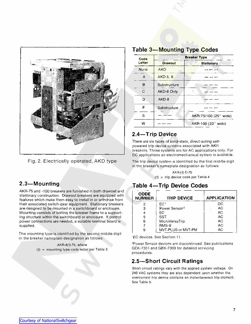
Fig. 2. Electrically operated, AKD type
2.3-MountingAKR-75 and -100 breakers are furnished in both drawout andstationary construction. Drawout breakers are equipped withfeatures which make them easy to install in or withdraw fromtheir associated switch-gear equipment. Stationary breakersare designed to be mounted in a switchboard or enclosure.Mounting consists of bolting the breaker frame to a supporting structure within the switchboard or enclosure. If controlpower connections are needed, a suitable terminal board issupplied.
The mounting type is identified by the second middle digitin the breaker nameplate designation as follows:
AKR-4(tJ-75, where(t) = mounting type code letter per Table 3
Table 3-Mounting Type CodesCode Breaker Type
Letter Drawout Stationary
None AKD ---
A AKD-5,6 ---
B Substructure ---C AKD-6 Only ---
D AKD-8 ---
F Substructure ---
S --- AKR-75/100 (25" wide)
W --- AKR-100 (33" wide)
2.4-Trip DeviceThere are six types of solid-state, direct-acting selfpowered trip device systems associated with AKRbreakers. These systems are for AC applications only. ForDC applications an electromechanical system is available.
The trip device system is identified by the first middle digitin the breaker's nameplate designation as follows:
AKR-(t) C-75(t) = trip device code per Table 4
Table 4-Trip Device CodesCODE
NUMBER TRIP DEVICE APPLICATION
2 EC' DC3 Power Sensor 2 AC4 EC AC5 SST AC6 MicroVersaTrip AC7 RMS-9 AC9 MVT-PLUS or MVT-PM AC
'EC devices. See Section 11.
2Power Sensor devices are discontinued. See publicationsGEK-7301 and GEK-7309 for detailed servicingprocedures.
2.5-Short Circuit RatingsShort circuit ratings vary with the applied system voltage. On240 VAC systems they are also dependent upon whether theovercurrent trip device contains an instantaneous trip element.See Table 5.
7
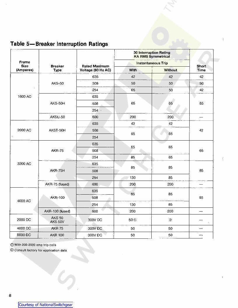
Table 5-Breaker Interruption Ratings30 Interruption RatingKA RMS Symmetrical
Frame Instantaneous TripSize Breaker Rated Maximum Short
(Amperes) Type Voltage (60 Hz AC) With Without Time
635 42 42 42
AKS-50 508 50 50 50
254 65 50 42
1600 AC 635
AKS-50H 508 65 65 65
254
AKSU-50 600 200 200 -635 42 42
2000 AC AKST-50H 508 4265 65
254
63565 65
AKR-75 508 65
254 85 65
3200 AC 63585 85
AKR-75H 508 85
254 130 85
AKR-75 (fused) 600 200 200 -
63585 85
AKR-100 508 854000 AC
254 130 85
AKR-100 (fused) 600 200 200 -
2000 DC AKS50300V DC 50 CD (2)
AKS 50V-
4000 DC AKR 75 300V DC 50 50 -6000 DC AKR 100 300iJ DC 50 50 -
Q) With 200-2000 amp trip coils
® Consult factory for application data
8

SECTION 3-Storage, Safety &Maintenance
3.1-StorageIt is recommended that the breaker be put into serviceimmediately in its permanent location. If this is notpossible, the following precautions must be taken to insurethe p roper storage of the breaker:
1. The breaker should be carefully protected againstcondensation, preferably by storing it in a warmdry room, since water absorption has an adverseeffect on the insulation parts. Circuit breakers foroutdoor switchgear should be stored in theequipment only when power is available and theheaters are in operation to prevent condensation.
2. The breaker should be stored in a clean locationfree from corrosive gases or fumes. Particular careshould be taken to protect the equipment frommoisture and cement dust, as this combination hasa very corrosive effect on many parts.
CAUTION: IF THE BREAKER IS STORED FORANY LENGTH OF TIME, IT SHOULD BEINSPECTED PERIODICALLY TO SEE THATRUSTING HAS NOT STARTED AND TOASSURE GOOD MECHANICAL CONDITION.SHOULD THE BREAKER BE STORED UNDERUNFAVORABLE ATMOSPHERIC CONDITIONS. IT SHOULD BE CLEANED AND DRIEDOUT BEFORE BEING PLACED IN SERVICE.
3.2Each user must maintain a safety program for the protectionof personnel, as well as other equipment, from the potentialhazards associated with electrical equipment.
The following requirements are intended to augment theuser's safety program, but NOT supplant the user's responsibility for devising a complete safety program. The following basic industry practiced safety requirements are applicable to all major electrical equipment such as switchgear orswitchboards. General Electric neither condones nor assumesany responsibility for practices which deviate from the following:
1. ALL CONDUCTORS MUST BE ASSUMED TO BE ENERGIZED UNLESS THEIR POTENTIAL HAS BEEN MEASURED ASGROUND AND SUITABLE GROUNDING CONDUCTORS HAVEBEEN APPLIED TO PREVENT ENERGIZING. Many accidentshave been caused by back feeds from a wide variety ofsources.
2. Although interlocks to reduce some of the risks are provided,the individual's actions while performing service or maintenanceare essential to prevent accidents. Each person's knowledge;his mental awareness; and his planned and executed actionsoften determine if an accident will occur. The most importantmethod of avoiding accidents is for all associated personnel tocarefully apply a thorough :.Jnderstanding of the specific equiprrent from the viewpoints of it's purpose, it's construction, it'sopJration and the situations which could be hazardous.
All personnel associated with installation, operation and maintenance of electrical equipment, such as power circuit breakersand other power handling equipment, must be thoroughly instructed, with periodic retraining, regarding power equipment ingeneral as well as the particular model of equipment with whichthey are working. Instruction books, actual devices and appropriate safety and maintenance practices such as OSHA publica-
tions, National Electric Safety Code (ANSI C2), The NationalElectrical Code, and NFPA 70B Electrical Equipment Maintenance must be closely studied and followed. During actualwork, supervision should audit practices to assure conformance.
3. Excellent maintenance is essential for reliability and safety ofany electrical equipment. Industry publications of recommended maintenance practices such as ANSI/NFPA 70B, Electrical Equipment Maintenance, should be carefully studied andapplied in each user's formation of planned maintenance.
3.3Both long and short term maintenance of all electrical equipment is essential for reliability and safety. Maintenance programs must be tuned to the specific application, well plannedand carried out consistent with both industry experience andmanufacturer's recommendations. Local environment mustalways be considered in such programs, including such variables as ambient temperatures, extreme moisture, number ofoperations, corrosive atmosphere or major insect problemsand any other unusual or abusive condition of the application.
One of the critical service activities, sometimes neglected,involves the calibration of various control devices. Thesemonitor conditions in the primary and secondary circuits,sometimes initiating emergency corrective action such asopening or closing circuit breakers. In view of the vital roleof these deVices, it is important that a periodic test programbe followed. As was outlined above, it is recognized that theinterval between periodic checks will vary depending uponenvironment, the type of device and the user's experience. Itis the General Electric recommendation that, until the userhas accumulated enough experience to select a test intervalbetter suited to his indiVidual requirements, all significantcalibrations be checked at an interval of one to two years.
To accomplish this, some items, such as "EC" direct operatingtrip systems for low voltage breakers, must be tested withprimary current injection. Others can be adequately testedusing test sets. Specific calibration instructions on particulardevices typically are provided by supplied instruction books.
Instruction books supplied by manufacturers address components that would normaliy require service or maintenanceduring the useful life of the equipment. However, they cannot include every possible part that could require attention,particularly over a very long service period or under adverseenvironments. Maintenance personnel must be alert to deterioration of any part of the supplied switchgear, taking actions, as necessary to restore it to serviceable status.
Industry publications of recommended maintenance practicessuch as ANSIINFPA 70B, Electrical EqUipment Maintenance,should be carefully studied and applied in each user's formation of planned maintenqnce.
Some users may require additional assistance from GeneralElectric in the planning and performance of maintenance.The General Electric Company can be contracted to eitherundertake maintenance or to provide technical assistancesuch as the latest pUblications.
The performance and safety of this equipment may be compromised by the modification of supplied parts or their replacement by non identical substitutes. All such designchanges must be qualified to ANSI/IEEE Standard C37.59.
The user should methodically keep wr(tten maintenancerecords as an aid in future service planning and equipmentreliability improvement. Unusual experiences should bepromptly communicated to the General Electric Company.
9

SECTION 4-Breaker Operation
Breaker OperationThe AKS-50, AKR-75 and AKR-100 breakers are closed bythe discharging of the energy stored in the closing springsof the breaker. As the closing springs are discharged, theenergy is directed into the closing cam of the breakerwhich causes the moveable breaker contacts to be forcedagainst the stationary contacts, and, at the same timecauses the opening springs to be charged so they mayopen the breaker during a subsequent opening operation.
4.1-Manual ClosingManually operated breakers are equipped with a handlewhich extends from the escutcheon of the breaker.Alternately rotating the closing handle counterclockwisethen clockwise through approximately 120 degrees ofrotation through four complete cycles will cause thebreaker to close. During the four counterclockwisemovements and the first three clockwise movements of thehandle, the springs are progressively charged. Afterapproximately seven degrees travel of the fourth clockwisehandle movement, the spring charge mechanism is driven"over center" and the energy stored in the closing springsis directed into the closing cam and causes the breaker toclose. A charge-indicator, numbered one to four, visiblethrough the breaker escutcheon, indicates the number ofcomplete handle movements that have been performed.
4.2-Electrical ClosingOn electrically operated breakers, the closing springs arecharged by a gear motor. With the springs discharged, voltage applied to the control circuit will energize the motorthrough the "G" switch contacts-see figs. 3A & 3B. The motor, through the gear reduction output crank, compresses theclosing springs until they are fully charged. As this fullycharged position is reached, mechanically operated switch"G" reverses its shown position, deenergizing the motor. Inthe fig. 3A diagram switch "F" reverses its position and establishes a circuit for the "X" relay. At the same time, a mechanical prop is positioned to prevent the discharge of thefully charged closing spring.
With the closing spring pr-opped fully-charged, the breakeris ready for closing. This may be accomplished electricallyby depressing the closing button on the bre'aker (if soequipped) or by a remote closing switch. Operation of theclosing switch energizes the "X" relay, which in turnenergizes the closing solenoid. This removes the prop,releasing the closing springs to close the breaker.
As the closing relay is energized, it energizes anti-pumprelay "W". If the closing switch is maintained closed, theanti-pump relay will remain picked-up to prevent a secondclosing operation on the breaker in the event it is trippedopen automatically. The closing impulse must be releasedand reapplied before a second closing operation can occur.
CONTROLSOURCE
CC
TC
LEGEND
CC - CLOSING SOLENOID
F - CUTOFF SWITCH, CLOSEDWHEN CLOSING SPRING ISFULLY CHARGED.
G - CUTOFF SWITCH. OPEN WHENCLOSING SPRING ISFULLY CHARGED.
L - AUXILIARY SWITCH
M - CHARGING MOTOR
PB - CLOSE PUSHBUnON ONBREAKER ESCUTCHEON,OPTIONAL.
TC - SHUNT TRIP DEVICE
W - ANTI-PUMP RELAY
X - CONTROL RELAY
Fig.3A. Elementary diagram for electrically operated drawout breaker.Contact positions are shown with breaker open and closing springs discharged.
TYP #5688736 "R" series.
10

4.2.1-Alternate Control CircuitLater production breakers use the electrical control circuitshown in Fig. 3B. This circuit is similar to the circuit shownin Fig. 3A except that the X-relay and 'F' switch are eliminated.
The motor is energized through the 'G' switch and the Wrelay contact. The 'G' switch deenergizes the motor whenthe closing springs are charged and the prop is engaged.
With the closing spring propped fUlly-charged, the breakeris ready for closing. This may be accomplished electricallyby depressing the closing switch on the breaker (if so
equipped) or by a remote closing switch. Operation of theclosing switch energizes the W-relay, which in turnenergizes the closing solenoid. This removes the prop,releasing the closing springs to close the breaker.
If the closing switch is maintained closed, the anti-pump relay will remain picked-up to prevent a second motor chargeand closing operation on the breaker in the event it is trippedopen automatically. The closing impulse must be releasedand reapplied after the closing springs are fully-charged before a second closing operation can occur. The chargingtime is typically 1 to 3 seconds depending on voltage andthe maximum time permitted is 5 seconds.
TC
LEGEND
CC - CLOSING SOLENOID
G - CUTOFF SWITCH. OPEN WHENCLOSING SPRING ISFULLY CHARGED.
L - AUXILIARY SWITCH
M - CHARGING MOTOR
PB - CLOSE PUSHBUTTON ONBREAKER ESCUTCHEON,OPTIONAL.
TC ....... SHUNT TRIP DEVICE
W - ANTI-PUMP RELAY
w
t~ PB
CC
L
W
REMOTECLOSE
0-------0- - -1 ~ -..,)...
CONTROLSOURCE
Fig. 38. Alternate elementary diagram. Contact positions are shown breaker open andclosing springs discharged. TYP #5688736 "8" series.
11

SECTION 4-Breaker Operation
4.3-Connections 4.3.1-Stationary BreakerIn all electrical connections good joint conductivity is amust. When making power connections to stationarybreakers, the mating joint surfaces must be clean and havea smooth finish. They should be parallel and firmly boltedor clamped together. In addition, the bus or cableconductors must have ample ampacity to preventoverheat ing.
The outgoing connections to breaker accessories andcontrol devices must be in accordance with the specificwiring diagram applicable to that breaker.
Control connections to stationary breakers are made to aterminal board mounted on the breaker. Figure 4 showstypical closing and tripping connections. If equipped withan overcurrent trip device which includes a ground faultelement for use on 4-wire circuits, an additional terminalboard is provided on the breaker for connecting to theequipment-mounted neutral sensor (physically located inthe neutral conductor).
4.3.2-Drawout BreakerOn drawout breakers the control circuits terminate in thebreaker compartment on the stationary portion ofseparable secondary disconnects - see fig. 5.
5 6 7 8 9 10TO AUX. SW"a" CONTACT
REVERSECURRENTDEVICEPOTENTIALSOURCE
1-) 1+)
"-t---'UV
TRIPSOURCE
'-.,-'
TRIPSOURCE
o 0 0 0 0 0Q d 9 0TERMINAL BOARD 2 3 4MOUNTED ON FRONTOF BREAKER ATUPPER LEFT
CUSTOMERCONNECTIONS
'-.,-'CLOSINGSOURCE
Fig. 4. Control connections to stationary breakers-front view
765432
/\ /\ /\ /\ /\ /\ /\
765432
IY)}CLOSINGSOURCE
IX)
/\/\/\/\/\/\/\
765432
FUSE
{
IYI
TRIPSOURCE
(X)~
TRIP
STATIONARY SECONDARY DISCONNECT BLOCKSLOCATED AT TOP OF COMPARTMENT POSITIONS BAND C FURNISHEDONLY WHEN-REQUIRED
1 JFig. 5. Control connections to drawout breakers - front view of breaker compartment
12

4.4-TrippingIn the closed position, the breaker movable contacts areheld in by a toggle linkage, The breaker is tripped open bydisplacing a mechanism latch which allows this togglelinkage to collapse, The trip latch is rigidly fastened to ahorizontal trip shaft running from left to right through thebreaker, In turn, the trip shaft carries paddles actuated bythe manual trip button and the various other trip devicesovercurrent, reverse current, shunt trip, undervoltage,open fuse lockout. Viewing the breaker from the right,rotating the trip shaft counterclockwise trips the breaker;clockwise movement resets the mechanism latch,
In addition to tripping the breaker, some devices hold thebreaker trip free, i.e" prevent the contacts from closingeven though a closing impulse is applied to themechanism. Such devices are the undervoltage, bell alarmand lockout, electric lockout, open fuse lockout, and thekey operated locks.
These devices and the drawout mechanism interlocks mustbe in the reset position before the breaker can be closed.
4.5-Charging and Closing Usingthe Maintenance Handle
In the absence of control power, an electric breaker can beclosed manually by using the maintenance handle tocharge the closing springs. Referring to Fig. 6:
(a) With the breaker open and springs dischargedrelease holding pawl slide per instruction label (2).
(b) Install maintenance crank (1) (5686386Gl) to the motorgear reducer shaft on the front right side of the breaker. Ratchet the maintenance crank up and down until the springs arefully charged as indicated by the distinct click as the prop isset. This prevents any further charging of the closing springs.After the prop is set do not apply undue force to themaintenance handle.
(c) Depress the "Spring Discharge" lever (3) locatedunder the horizontal su pport on the front frame. Thesprings should discharge and if the latch is properly reset,the breaker will close. Some style breakers, because of aninterlock in the SWitchgear, can not be manually closed inthe fully engaged position.
(d) Open the breaker by pushing the trip button (4).
1. Maintenance crank2. Instruction label3. Spring discharge lever4. Trip button
Fig. 6. Maintenance handle charging
13

SECTION 5-Contact Maintenance
Contact MaintenanceBreakers subjected to frequent interruption of highcurrents may eventually require replacement of theircontacts. The general rule for determining need ofreplacement is the loss of one-half or more of the mass ofthe contact tip material. Roughening or light pitting of thecontact surface does not indicate loss of ability to carry orinterru pt cu rrent.
For proper operation of the breaker, the contact structuresmust be correctly adjusted. Various interrelatedadjustment parameters are involved. Specific amount ofcontact pressure and wipe must exist between moveableand stationary contacts, The arcing, intermediate and maincontact assemblies must engage and disengage in aprescribed sequence; and with breaker open, an adequategap must exist between the movable and stationary arcingcontacts.
5.1-Slow Closing the BreakerTo perform contact maintenance work the breakeroperating mechanism must be "slow-closed", i.e. manuallydriven and controlled at will instead of in the high-speedmanner produced by spring discharge. Slow closing isachieved by preventing the closing springs from acting onthe mechanism. The breaker is arranged for slow closingby manually charging the springs and then securing themin this compressed state by inserting a restraining "safetypin" see Fig. 7.
Following the inspection period,
a. Recharge the closing springs.
b. Remove the safety pins from the guide rods, returnthem to thei r storage clips.
14
5.1.1-Electrical BreakerReferring to Fig. 7:
a. Attach maintenance handle (1) and charge theclosing springs until the crank roller contacts prop (4).
b. Insert safety pins (3) into the holes in the guide rods(2).
c. Release the prop by depressing closing lever (5). Thesafety pin now takes the full force of the spring andrestrains it. Now free from spring influence, the breakercontacts can be inspected and moved at will to the fullyclosed position by means of the maintenance handle.
5.1.2-M anual Breakera. Operate the breaker closing handle through 3%
complete movements to charge the closing springs.
b. Insert the safety pins into the gUide rods.
c. Continue to operate the closing handle (4thdownstroke) until the spring crank goes over center,applying full spring force to the safety pin. Closing motionnow can be continued and is completely controlled by thebreaker closing handle.
WARNING: DO NOT APPLY CONTROLVOLTAGE OR RACK THE BREAKER INTOTHE TEST OR CONNECTED POSITIONSWHILE THE SAFETY PINS ARE IN USE.

1. Maintenance2. Guide rods3. Safety pins
4. Prop5. Closing springs
Fig. 7. Installation of safety pin
5.2-Arc Quencher Removal andInspection
The arc quenchers should be inspected at the regular inspection period. If item 1 is eroded to .125 of an inch fromoriginal conture or item 2 is cracked, Fig. 8, the arc quenchershould be replaced.
5.2.1-Removal and ReplacementReferring to Fig. 8:
a. Be sure breaker is open.
b. Loosen nuts (4) and remove the two slotted head jackscrews.
c. Remove two hex head bolts (5) that mount channelshaped retaining bar to side support (6).
d. Remove channel-shaped retaining bar.
(Continued next page)
15

SECTION 5-Contact Maintenance
1., 2. & 3. Barriers4. Nuts5. Hex head bolts6. Side support7. Protective, barrierB. Phase barrier screws9. Mounting bolts
Fig. 8. Arc quencher removal
Original design
e. Lift arc quenchers clear of the movable arcing contactarms.
f. Inspect arc quenchers carefully and replace ifnecessary.
g. During replacement, tighten jack screw nuts (4) first,then the two hex head bolts that secure the channelshaped retaining bar to side sheet. DO NOTOVERTIGHTEN THESE TWO SOLTS.
16
5.3-Separation of Front andBack Frames
In order to perform some repair and replacementoperation, the front frame must be separated from the backframe. Proceed as follows: referring to Fig. 9.
a. Open the breaker, manually compress the closingsprings and insert the safety pin as described underSLOW CLOSING, Section 5.1. Restraining the springsproperly positions the main operating cam to facilitate theseparation operation.

~-
E1-
1]-
1. Opening springs2. Clevis pin3. Front/back frame
connector
4. Flux shifter actuator bracket5. Auxiliary switch
operating rod6. Phase barriers
7. Side support bolts8. Position interlock9. Arc quencher retainer bolts
Fig. 9. Front and back frame separation details
b. Remove the two opening springs (1) (on lower part ofthe breaker) from the outside pole units.
c. Remove the clevis pin (2) from the center pole unit.
d. Disconnect the programmer CT wire harness at each CTand remove any tye wraps holding leads to back frame.
e. Disconnect the flux shifter actuator bracket from thecrossbar assembly (4).
f. Remove the auxiliary switch operating rod (5).
g. Remove outside phase barriers (6).
h. Remove side support bolts (7).
i. Remove position interlock on AKD, AKD 5. AKD6 type (8).
j. Remove arc quencher retainer and bolts (9).
k. Remove the six nuts from the back frame using asocket wrench with an extension. These include the twonuts at the top of the frame.
I. Check along the trip shaft for a mechanicalinterference or connection between the overcurrent tripdevice and the trip paddles. Remove mechanicalconnection if present, or if interference exists, use extremecare when removing or reassembling front and backframes to avoid mechanical breakage of trip devices.
When reassembling the front and back frames, both shouldbe positioned vertically so that the trip shaft is horizontallyaligned. It is recommended that the breaker back framebe fastened to a suitable mounting surface so that the frontframe can be supported by a sling or hook as the bolts arebeing installed.
17

SECTION 5-Contact Maintenance
BACK FRAME ASSEMBLY
5.4-Back Frame AssemblyThe breaker backframe consists of a frame assembly towhich the pole units are mounted. Each pole unit isconnected to a common crossbar which provides forsimultaneous pole unit operation by the breakersmechanism. A typical backframe is shown in Fig. 10.
The pole units consist of a molded base which supportsthe line and load stud assemblies, stationary and moveablecontact assemblies and the actuating linkage.
The stationary main contact assembly (9) comprises of aspring loaded contact fingers. Interlocked with these arethe intermediate contact fingers (7) whose contact surfaceproject beyond that of the mai n such that theintermediates make before, and break after the mains.
1. Crossbar2. Pole unit3. Stationary arcing contact4. Pin-stationary arcing5. Moveable arcing contact6. Pin-moveable arcing
Mating with the stationary contacts is a moveable contactassembly consisting of multiple main and intermediate contact fingers (10) and (8). These moveable contact fingerspivot on a stationary pin (11), which fasten them to the lowercontact block. The insulated link (13) which is attached tothe breaker crossbar (1) and moveable contact assemblygives the open and close motion to the contact arm.
The stationary arcing contact assembly (3) is a separateset of contact fingers, pins, springs and pivot block.
The moveable arcing contact assembly (5) consists ofmultiple contact arms carried on two moveable pins (6)and (12). The arcing contact arms interleave the maincontacts and pivot with them about pin (6). This relativemotion is obtained by the insulating links (13) from thecontact arms to the breaker crossbar.
7. Stationary intermediate contact8. Moveable intermediate contact9. Stationary main contact
10. Moveable main contact11. Pivot pins12. Drive pins13. Insulated link
Fig. 10. Front view of back frame assembly
18

5.5-Measuring Contact Forcea. Remove the arc quenchers.
b. Separate front and back frames, refer toSection 5.3
c. Inspect all contacts for wear and arc erosion and,if necessary, replace (see criteria for replacement, Section5.10)
d. Measure contact force only if you replace contactarms.
5.5.1-Stationary Arcing ContactsReferring to Fig. 11:
Place a push scale on the stationary arcing contact at apoi nt 1-3/16 from the contact pivot and depress thatcontact 1/4 of an inch. Load on the scale should readwithin the range listed in Table 6, column 8.
If the load is not within the range listed in column 8,replace the spring under that contact assembly.
5.5.2-Stationary Main andIntermediate Contacts
Place a push scale on the stationary contact at a point 27/8 from the contact pivot and depress that contact to thewipe dimension shown in Table 6, column 3 for the mainsand column 6 for the intermediates. Load on the scaleshould read within the range listed in Table 6, column 2 forthe mains and column 5 for the intermediates.
If the load is not within the range listed replace the springunder that contact assembly.
5.6-Measuring Contact WipeReferring to Fig.11:
a. Remove arc quenchers.
b. With the breaker open measure the horizontal distancefrom the edge of the stationary arcing contact to the retainer("A" dim.); for main and intermediate contacts measure thehorizontal distance from the top of the cont act to the contactarm retainer ("8" dim.).
c. Close the breaker and repeat step b. The differencebetween the readings determines the contact wipe.
See Table 6 for correct readings.
CAUTION: FOR SAFETY REASONS BEEXTREMELY CAREFUL NOT TO TRIP THEBREAKER WHEN MEASURING CONTACTWIPE.
5.7-Adjusting Contact WipeReferring to Fig. 11:
a. To obtain proper contact wipe and pressure on thecenter pole, dimension "C" should be increased toincrease wipe and decreased to decrease wipe.
b. To change dimension "COO remove the clevis pin androtate the clevis as necessary.
c. To prevent overstressing the clevis threads dimension"COO should not exceed 3/16 in. and space "COO should befilled with shims to 0.005 in. of being solid. "
d. With the proper center pole wipe obtained, movingthe crossbar adjusti ng plate on the center pole to the rightwill simultaneously increase the wipe on both outsidepoles; moving the adjusting plate to the left will have thereverse effect.
e. To increase the wipe on either outside pole, individuallymove the crossbar adjusting plate of that pole to the left; todecrease the wipe move the adjusting plate to the right. SeeSection 5.11.
19

SECTION 5-Contact Maintenance
StationaryArcing Contact
/Open gap2'12 to 2314
A_.v--+~
UPPERSTUD
Stationary main contactLowerStud
Clevis(centerpole)
Fig. 11. Measuring contact force
Table 6Main Contacts Intermediate Contacts Arcing Contacts
Column 1 2 3 4 5 6 7 8 9
Wipe Wipe WipeOty. Force in Oty. Force in Oty. Force In
Breaker Per in Inches Per in Inches Per in InchesType Pole Lbs. (B) Pole Lbs. (B) Pole Lbs. (A)
AKS-50 (AC) 3 1 · 2AKS-!iO 10C;\ ~
35-551
35-55 · 3 5/32 toAKR-75 (AC) 5
'/'6 to 1 · 3 31-43 9/32AKR-75 (DC) 5
25-55 '/641 25-55 · 5
AKR-100 (AC/DC) 6 2 · 5
'The intermediate contact wipe should be at least '/16 in. greater than main contact wipe.
20

5.B-Measuring Contact Open GapPrior to measuring the open gap verify that the cross armbuffer assemblies, refer to Fig. 12, are touching. The stackup dimension of each buffer should be within .015" of eachother. Adjust to this dimension by adding or removing washers.
~
iF
Measure the contact open gap between the movable andstationary contacts as shown in Fig. 13. This distanceshould be between 2-1/2" to 2-3/4". This gap may beadjusted by repositioning shims on crossbar assembly.The locking nuts on the buffer bolts should be locked insuch a position that the buffer bolt may be rotated freely.
1-Buffer stop2-Buffer washers3-Buffer shims4-Lock nuts
Fig. 12. Buffer assembly
Fig. 13. Measuring contact open gap
21

SECTION 5-Contact Maintenance
5.9-Checking Contact SequenceOn the horizontal plane, the difference in the making of thearci ng contacts on the same pole must be no greater than1/16 in.; this difference between arcing contacts onseparate poles must be 1/16 in. If it is desired to advanceor retard the closing of the main contacts of a pole, loosenthe bolts holding the adjustment plate, refer to Fig. 21, ofthat pole and slide plate to the left to advance contactclosing, or to the right to retard contact closing. Make thisadjustment on the outer poles, using the center pole as areference. Upon retightening adjustment plate bolts, makesure the locking tabs are turned up around bolt heads,locking the bolts securely in place.
Contact sequence in the vertical plane should be such thatwhen the arcing contacts are just touching, theintermediate contact gap should be at least 3/16 in. andthe main contacts gap at least 1/4 in., see Fig. 14.
NOTE: This check can best be made by meansof the maintenance handle, with the safety pinrestraining the closing springs. See Section 5.1for this procedure.
5.10-Replacement of ContactsCriteria for replacement:
a. Arcing contacts should be replaced when eroded to athickness of 5/64.
b. Intermediate contacts should be replaced when flushwith main contacts (.062 lead when new).
c. Main contact very seldom needs replacement.Replace when arcing contacts have been neglectedcausing severe erosion of mains so you can not obtainproper contact depression.
When replacing the arcing contact assemblies you do nothave to separate the front frame from the back frame.
5.1 O.1-Stationary Arcing Contactsa. Refer to Fig. 15.
b. Remove insulator block (1).
c. Slide pin (2) to side. Contact assembly (3) will liftfreely exposing two springs (4) and button (5) ..
d. Install new parts inreverse order.
5.10.2-Movable Arcing Contacts
Fig. 15. Replacement of stationary andmovable arcing contacts
These contact arms should be replaced whenever the stationary arcing contacts are replaced.
a. Refer to Fig. 15.
b. Remove retaining rings (6). Slide pins to side andwithdraw the contact arms.
4. Springs5. Button6. Retaining rings
1. Insulator block2. Pin3. Contact assembly
Fig. 14. Measuring main contact gap
If the gap is under the required minimum, it is usually possible to form the arcing contacts and obtain the required dimensions. To form the contacts, place a piece of conduitapproximately two feet long, over the contact and form thecontact either forward or backward by bending it. If theproper dimensions are still not obtained, the moveable arcing contacts should be replaced.
If it has been necessary to make any adjustments whileobtaining proper contact sequence, the contact wipe mustbe checked, and adjusted, if necessary, see Section 5.6.

5.10.3-Moveable Main andIntermediate Contacts
a. Refer to Fig. 16.
b. Loosen crossbar bolts so link (10) can move freely.
c. Remove retaining rings (7) from pins (8).
Slide pins (8) until contact arms can be withdrawn.
iE----
d. Remove contact arms, noting two spring washers (9)on each contact pivot.
Upon re-assembly, position two spring washers intocounter bore on one side of contact arm (9). Note left andright hand orientation of contact arms and position ofintermediate contact.
e. Before tightening crossbar see assembly andadjustment of crossbar, Section 5.11.
7. Retaining rings8. Pins9. Spring washers
10. Crossbar bolts11. Intermediate contact
Fig. 16. Replacement of main and intermediate contacts
23

SECTION 5-Contact Maintenance
5.10.4-Stationary Intermediate andMain Contacts
a. Separate the front frame from the back frame. Referto Section 5.3.
b. Remove crossbar.
NOTE:ln the steps below, refer to Fig. 17 toidentify the numbers in the parenthesis.
c. Remove arcing contact block (3) by removing allenscrews (4) and (5).
d. Depress main and intermediate contacts as shown inFig. 18 to relieve spring pressure on contact stop bracket(6) before removing mounting screws. On AKR100 youmust remove the outside moveable contact arm beforetrying to remove contact stop bracket mounting screws.
e. Remove retaining ring (7) and slide pin (8) to side andwithdraw the contact arm. Fig. 17.
1. Main contact arm2. Intermediate contact arm3. Arcing contact block4. Arcing contact5. Allen screws6. Contact stop bracket7. Retaining ring8. Pivot pin
Fig. 17. Intermediate and main contactsassembly details
24
f. Remove contact, noting two spring washers on eachcontact pivot. Upon re-assembly, position two springwashers into counter bore on one side of contact arm. Fig.19.
NOTE: Left and righthand orientation ofcontact arms and position of intermediatecontact. Fig. 19.
g. Depress main and intermediate contacts to relievespring pressure on contact stop bracket before startingscrews. Tighten screws before releasing pressure.Fig. 18.
h. Re-install arcing contact block by holding arcingcontacts depressed (Fig. 20) while tightening screws.
i. Assemble crossbar.
j. Always check contact wipe following contactreplacement. See Secton 5.6.
ill6. Contact stop bracket
Fig. 18. Relieving spring pressure

Fig. 19. Upper stud details
5.11-Assembly and Adjustment ofCrossbar
When assembling crossbar to back frame push moveablearcing contacts forward until they touch stationary arcingcontacts on upper terminal. Then lay crossbar on top oflinks on pole units. Assemble adjusting plates as shownmaking sure slots in plates are properly oriented. Fasten
Fig. 20. Re-assembly of arcing contacts
screws with locking plates on crossbar finger tight and setcrossbar to dimension shown making sure that all threepoles of moveable arcing contacts are touching stationaryarcing contacts within .032. Tighten screws as shown first"A", second "B", and finally "C" to 400 inch pounds. Bendtabs on locking plates to secure screws. Refer to Fig. 21.After assembling crossbar always check contact wipe andopen gap, see Sections 5.6 thru 5.8.
1. Crossbar2. Stationary arcing contacts
3. Moveable arcing contacts4. Adjustment plates
Fig. 21. Crossbar assembly
25

SECTION 6-Breaker Maintenance
Breaker Maintenance
6.1-Safety PrecautionsBEFORE INSPECTION OR ANYMAINTENANCE WORK IS DONE BE SURETHAT THE BREAKER IS IN THE OPENPOSITION. ALL ELECTRICAL POWER, BOTHPRIMARY AND CONTROL SOURCES,SHOULD ALSO BE DISCONNECTED.ENSURE THAT THE CLOSING SPRINGS AREDISCHARGED.
6.2-LubricationIn general, the circuit breaker requires moderate lubrication.Bearing points and sliding surfaces should be lubricated atthe regular inspection periods with a thin film of GE Lubricant050HD38 (D6A15A1 Mobilgrease 28). Before lubricating, remove any hardened grease and dirt from latch and bearingsurfaces with kerosene. ALL EXCESS LUBRICANT SHOULDBE REMOVED WITH A CLEAN CLOTH TO AVOID ACCUMULATION OF DIRT OR DUST.
NOTE: The use of cotton waste to wipe bearingsurfaces should be avoided, as the cottonravelings may become entangled under thebearing surfaces and destroy the surface of thebearing.
On drawout breakers the contact surface of the disconnectstuds should be cleaned and greased with GE LubricantD50H 038 (D6A15A1 Mobilgrease 28).
Fig. 22A. Mechanism in motion beforeresetting as shown in Fig. 22C
26
6.3-Breaker MechanismAdjustments
Electric and Manual breakers have the same basicmechanism shown in Fig. 22. All the adjustments detailedbelow must be made with the breaker in the uprightposition and the mechanism in the reset position as shownin Fig. 22B. Reset the mechanism by manual operationusing the slow close method given in Section 5.1. Theroller (15) must be clear of the cam (2), see Fig. 22C.
6.3.1-Trip LatchReferring to Figs. 22C, 220 & 23, the gap between the triplatch (10) and the roller (9) should be between .015 and.032. This adjustment can be obtained by loosening nut(19) and turning allen screw (6).
6.3.2-Latch BufferReferring to Fig. 220, the center line of the trip latch (10)should pass through the center of the roller (9). The latchbuffer (18) on the mechanism frame can be adjusted byloosening the retaining screws to reposition the latch withrespect to the roller.
6.3.3-Reset Latch, Bearingand Prop
Referring to Figs. 22C, 220 & 24, the distance between thebearing (17) and the prop (5) should be between .015 and.032. To obtain this gap, advance or retard the nuts (4A) onthe bottom of the rod using the reset spring (4).
Fig. 228. Mechanism in reset position

ill]
I
iJ'
~--It-I~
~ d
IIi- ---1
7----iE
11~----iE
[II
-ml>'-~J--~
Q---rlJ\\~,~:---a
.4t=====,;m~
~1. Spring2. Cam3. Link4. Reset spring
4A. Spring adjusting nuts5. Prop6. Adjusting screw7. Adjusting screw stop pin8. Prop return spring9. Roller
10. Trip latch11. Trip shaft12. Clevis pin13. Clevis14. Reset latch15. Roller16. Prop17. Bearing18. Buffer19. Nut
Fig. 22C. Mechanism in closed position(closing spring discharged)
-il-~
-~
Fig. 220. Latch, bearing, and prop
-il
-~
-f]
1. Feeler gage 2. Trip latch 3. Roller 1. Feeler gage 2. Prop 3. Bearing
Fig. 23. Adjusting trip latch and roller Fig. 24. Adjusting bearing and prop
27

SECTION 6-Breaker Maintenance
6.4-Electrical MechanismThe function of the electrical mechanism is to charge anddischarge the closing springs either electrically ormanually. The electrical mechanism consists of
a. Control components
b. Charging motor
c. Motor operator unit
d. Spring discharge interlock
Section 4.2 details the associated control circuitry for theelectrical mechanism.
6.4.1-Control ComponentsReferring to Fig. 25:
The control relay (X) is located on the left side of the frontframe channel. It may be removed by disconnecting thewiring, loosening the two mounting screws and lifting itslightly to pass the top mounting screw through thekeyhole mounting. The entire relay should be replacedrather than changing coils and contacts.
The antipump relay (W) is located on the left side of thefront channel. The connections to this relay are soldered.Relay replacement requires unsoldering of theseconnections and removing the mounting hardware. Whenreplacing relay take care in soldering connections. Do notuse excess amount of solder on connectors as to impairoperation of contact arms.
The closing solenoid is located in the lower right hand sideof the motor operator unit. The switchette is separatelymounted in front of the solenoid.
1. Terminal board2. Auxiliary switch3. F&G switches
4. Motor 7. Closing button5. Anti-pump relay (W) 8. Switchette6. Control relay (X) 9. Closing solenoid
Fig. 25. Control component location
28

After replacing closing solenoid or switchette checkadjustment of switchette and readjust if necessary. Withbreaker in discharge position use a .010 feeler gage andpush closing solenoid to position shown in Fig. 26.Switchette must be activated at this point. To adjust loosenswitchette mounting screws and pivot switch untilactivated, then tighten screws. Recheck.
-iJ
//~
W.0'_.060,men","required with
, lever in posilionshown AdjustII necessary
Drille Link
Opening SpringBracket
MOlorAHembly
'----='l'+.IIF:1Io-""""~Retaining Ring
1. Driving pawl
MOTORmountingHardware
Fig. 27. Electrical mechanism
Fig. 28. Motor removal
OPERATORMountingHrmiwr.tre
MaintenanceHandle Shall
Opt>fd!,ng leyer
ConnectionPoints
~ Closing Solenoid
Fig. 26. Switchette adjustment
"0"
6.4.2-Charging MotorThe charging motor is located on the right side of thebreaker. It is mounted on the motor operator as shown inFig. 27. A driving pawl is mounted eccentrically on themotor shaft, see Fig. 28. As the motor turns, the drivingpawl rotates the ratchet which charges the closing springs.The ratchet is kept from reversing its direction by theholding pawl. To remove the motor:
a. On AKS 50 you must remove the side sheet.
b. Disconnect and identify the motor leads at the closingsolenoid and cutoff switch.
c. Remove three motor mounting screws.
d. Remove motor.
e. When reassembling, assemble with the driving pawlpointing toward the front of the breaker.See Fig. 28.
29

SECTION 6-Breaker Maintenance
6.4.3-Motor Operator UnitThe motor operator unit is located on the right hand sideof the breaker as shown in Fig. 29. Operator details areshown in Fig. 30.
1. Motor operator unit
Fig. 29. Motor operator unit location
The motor drives the crank roller/maintenance handleshaft until the control circuitry stops the motor and roller isagainst the prop. The crank roller drives the cam shaft,charging the spring, through the cam shaft paddle,see Fig. 31.
The motor operator unit is not adjustable. To replace theunit, refer to Fig. 27:
a. Slow close the breaker, see Section 5.1
b. Remove the motor, see Section 6.4.2. The motorwiring doesn't have to be disconnected.
c. Disconnect the wiring to the closing solenoid andsolenoid switch.
d. Remove retaining ring from closing solenoid drivelink.
e. Remove three mounting bolts, one from the side, twofrom the bottom of the charging mechanism. Note thepositions of the standoffs on the two bottom mountingbolts and replace in the same position when reassembling.
f. Rotate motor operator shaft so its crank roller facesthe rear of the breaker. Refer to Fig. 32.
g. Slide spring charging mechanism out toward the rightof the breaker.
h. Install new spring charging mechanism making surethe crank roller engages cam shaft guide. Refer toFigs. 31 and 33.
CamShaft Pivot
CrankRoller
1)= ===rl - - - -II II
I' "~'II : I
____l'==:=:J,L----Celm ShaftPaddle
Fig. 31. Engagement of the motor operatorcrank roller with the cam shaftpaddle
MaintenanceHandle Shaft
Fig. 30. Motor operator unit
30
MotorOperatorCrankRoller .Assembly Guide
r"T-t--_ era nkRoller

Fig. 32. Motor operator removal
1. Cam shaft paddle2. Guide
Fig. 33. Cam shaft lever and guide
i. Reassemble all components and connect all wires.
j. Remove safety pin from closing spring by placingyour maintenance handle on the shaft which extends fromthe spring charging mechanism and charge the closingspring until the charging mechanism roller engages withtile prop. Remove safety pin. This must be done beforepower is applied to motor.
k. Operate the breaker using the maintenance handleand spring discharge mechanism a few times. Verify thatthe breaker is operati ng properly.
I. Before applying control voltage to your breaker verifythat the motor cut off switches are properly adjusted.Charge the closing spring as described instep j. (roller resting on prop). Adjust the motor cut offswitches, shown in Fig. 35, so that they are depressed tothe point where the main stem of each switch is located.005" to .031" from the threaded barrel, see Fig. 34.
(Continued next page)
.031______ -4---
.005
Main Stem
Threaded Barrel
Fig. 34. Motor cutoff switch adjustment
31

Control VoltageNameplate
"G" Switch
"F" Switch
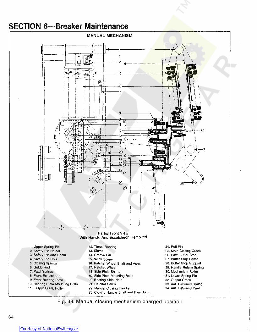
The manual AKR breaker is equipped with the springcharged, stored-energy mechanism shown inFigs. 37 & 38.
The stored-energy operating mechanism of a manualbreaker consists basically of a closing spring assembly,ratchet wheel and output crank assembly, handle shaft andpawl assembly, and the escutcheon-mounted closinghandle.
The closing springs (5) are charged by operating themanual closing handle (22) on the front of the breaker,instead of the closing motor as is the case with theelectrical breaker. Closing this breaker is accomplished bypumping the operating handle four complete cycles, firstcounterclockwise through 120 degrees from its normalvertical position and then clockwise back through 120degrees from its normal vertical position and thenclockwise back through 120 degrees. When approximately70 degrees of the fourth clockwise stroke have beencompleted, the closing springs, which have been chargedduring the previous strokes to the closing handle, aredriven over-center and the breaker closes.
Fig. 36. F & G switch location
6.S-Manual Mechanism
The first stroke of the closing handle causes the ratchetpawls (21) attached to the handle shaft (23), to engage thefirst tooth of the ratchet wheel (17), thus beginning tocharge the closing springs. The subsequent closing handlestrokes perform the same fu nction as the pawls (21)engage the teeth in the ratchet wheel (17), thus rotatingthe ratchet wheel and output crank (32) and completelycharging the closing springs. This rotation of the ratchetwheel and output crank is in a countercloskwise directionfrom the lower position, through slightly more than 180degrees, to a position just beyond dead center. In thisposition the closing springs are free to release theirenergy, closing the breaker at a high speed.
Right SideCenter Channel
SECTION 6-Breaker Maintenance6.4.3-Motor Operator Unit (Cont.)
m. When the control voltage is applied to your breaker,the motor operator will be energized and charge theclosing spring. The G switch (see Fig. 36) of the motor cutoff switch unit will stop the motor operator just before theroller engages the prop. The breaker may be closedmanually by depressing the spring discharge lever orelectrically by energizing the closing solenoid.
_ .l!
Spacer
Paddle ---'f-;;I
Fig. 35. Motor cutoff switch unit
6.4.4-Spring Discharge InterlockReferring to Figs. 27 & 30, the spring is discharged whenthe prop is pulled out from the roller. This is doneelectrically by the closing solenoid and manually by thespring discharge interlock.
The spring discharge interlock drive link must be adjustedto the .03 to .06 inch dimension shown in Fig. 27. This gapprovides the closing solenoid linkage the initial freedom itrequires to develop the force necessary to remove theprop.
32

1. Upper spring pin3. Safety pin and chain5. Closing springs7. Pawl springs
18. side plate shims19. Side plate mounting bolts20. Bearing side plate
21. Ratchet pawls25. Main closing crank26. Pawl buffer stop27. Buffer stop shims31. Lower spring pin33. Ant. rebound spring34. Ant. rebound pawl
Fig. 37. Manual closing mechanism
6.5.1-Mechanism PartReplacement
If it is necessary to replace any of the mechanism parts,the following total procedure is recommended. Thisprocedure may be halted at the step required to replaceany particular part. Referring to Figs. 37 & 38:
a. Install the safety pin (3) as described inSection 5.1.2.
b. Remove the closing spring assembly by removing theupper and lower spring pins (1,31).
c. Remove the right hand bearing side plate (20), andthe side plate shims (18) by removing four mounting bolts(19), thus allowing the main closing crank (25) to beremoved.
d. Remove the closing handle (22) by removing two setscrews threaded in same hole.
e. Remove the front escutcheon by removing fourscrews holding it to the front frame center support.
f. Remove handle shaft extension by removingroll pin.
g. Remove the handle return spring (29) by unhookingeither end of the spring.
h. Disconnect the top end of each pawl spring (7).
i. Remove the roll pin (24), thus allowing the closinghandle shaft and pawl assembly (23) to be removed.
j. Remove the ratchet wheel (17) and its assembly (16)by removing self locking screw (15) and thrust bearing(12). If shims (13) are present they must alsobe removed.
(Continued next page)
33
SECTION 6-Breaker MaintenanceMANUAL MECHANISM
31
3 4------~_+-lD\-____L
1E--+-+-++-t+----6---------+,---';--t--'R\
!Oi£-+----7
i i\II! !III
"
Partial Front ViewWith Handle And Escutcheon Removed
.'
r---jH ' \ '(\(), 28
il I
!i \ !~ I
Ji '..-,r~·- -~jJ
!j
~~~~y;--ti--5-------++;~
---------- -I---."...-~-::;;i
~.
!
I
II
!I;
I
II
§D
1, Upper Spring Pin2. Safety Pin Holder3. Safety Pin and Chain4. Safety Pin Hole5. Closing Springs6. Guide Rod7. Pawl Springs8. Front Escutcheon9. Front Bearing Plate
10. Bearing Plate Mounting Bolts11. Output Crank Roller
12. Thrust Bearing13. Shims14. Groove Pin15. Nylok Screw16. Ratchet Wheel Shaft and Asm.17. Ratchet Wheel18. Side Plate Shims19. Side Plate Mounting Bolts20. Bearing Side Plate
. 21. Ratchet Pawls22. Manual Closing Handle23. Closing Handle Shaft and Pawl Asm.
24. Roll Pin25. Main Closing Crank26. Pawl Buffer Stop27. Buffer Stop Shims28. Buffer Stop Support29. Handle Return Spring30. Mechanism Roller31. Lower Spring Pin32. Output Crank33. Ant. Rebound Spring34. Ant. Rebound Pawl
Fig. 38. Manual closing mechanism charged position
34
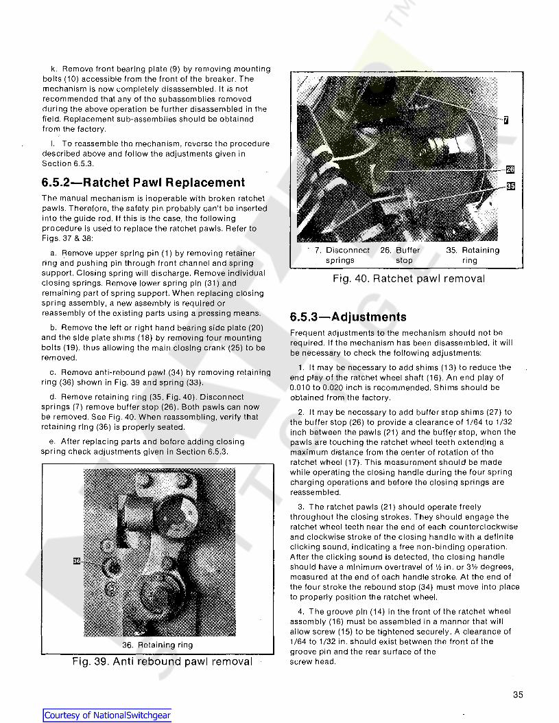
Fig. 40. Ratchet pawl removal
6.5.3-Adjustments
3. The ratchet pawls (21) should operate freelythroughout the closing strokes. They should engage theratchet wheel teeth near the end of each cou nterclockwiseand clockwise stroke of the closing handle with a definiteclicking sound, indicating a free non-binding operation.After the clicking sound is detected, the closing handleshould have a minimum overt ravel of 1/2 in. or 3V2 degrees,measured at the end of each handle stroke. At the end ofthe four stroke the rebound stop (34) must move into placeto properly position the ratchet wheel.
4. The groove pin (14) in the front of the ratchet wheelassembly (16) must be assembled in a manner that willallow screw (15) to be tightened securely. A clearance of1/64 to 1/32 in. should exist between the front of thegroove pin and the rear surface of thescrew head.
35. Retainingring
26. Bufferstop
. 7. Disconnectsprings
Frequent adjustments to the mechanism should not berequired. If the mechanism has been disassembled, it willbe necessary to check the following adjustments:
1. It may be necessary to add shims (13) to reduce theend play of the ratchet wheel shaft (16). An end play of0.010 to 0.020 inch is recommended. Shims should beobtained from the factory.
2. It may be necessary to add buffer stop shims (27) tothe buffer stop (26) to provide a clearance of 1/64 to 1/32inch between the pawls (21) and the buffE;H stop, when thepawls are touching the ratchet wheel teeth extend.ing amaximum distance from the center of rotation of theratchet wheel (17). This measurement should be madewhile operating the closing handle during the four springcharging operations and before the closing springs arereassembled.
Fig. 39. Anti rebound pawl removal
6.5.2-Ratchet Pawl Replacement
36. Retaining ring
k. Remove front bearing plate (9) by removing mountingbolts (10) accessible from the front of the breaker. Themechanism is now completely disassembled. It is notrecommended that any of the subassemblies removedduring the above operation be further disassembled in thefield. Replacement sub-assemblies should be obtainedfrom the factory.
I. To reassemble the mechanism, reverse the proceduredescribed above and follow the adjustments given inSection 6.5.3.
The manual mechanism is inoperable with broken ratchetpawls. Therefore, the safety pin probably can't be insertedinto the gUide rod. If this is the case, the followingprocedure is used to replace the ratchet pawls. Refer toFigs. 37 & 38:
a. Remove upper spring pin (1) by removing retainerring and pushing pin through front channel and springsupport. Closing spring will discharge. Remove individualclosing springs. Remove lower spring pin (31) andremaining part of spring support. When replacing closingspring assembly, a new assembly is required orreassembly of the existing parts using a pressing means.
b. Remove the left or right hand bearing side plate (20)and the side plate shims (18) by removing four mountingbolts (19), thus allowing the main closing crank (25) to beremoved.
c. Remove anti-rebound pawl (34) by removing retainingring (36) shown in Fig. 39 and spring (33).
d. Remove retaining ring (35, Fig. 40). Disconnectsprings (7) remove buffer stop (26). Both pawls can nowbe removed. See Fig. 40. When reassembling, verify thatretaining ring (36) is properly seated.
e. After replacing parts and before adding closingspri ng check adjustments given in Section 6.5.3.
35

SECTION 6-Breaker Maintenance
6.6-Drawout MechanismDrawout breakers are manuafactured in five differentstyles depending on the type of equipment that the breakerwill be used in. The mounting code and description ofeach style is found in GEI-86151 furnished with eachbreaker. If replacement of racking cam is needed thefollowing procedure should be used. See fig. 41.
a. Remove nut (1) and screw (2).
b. Loosen set screws in collar (3).
c. Remove racking cam assembly and replace with newcam.
d. Align center of worm with worm gear on racking camthen position collars firm against supports and tighten setscrews in collars.
To replace guide support (4):
a. Remove screws (5) and support (6).
b. Remove guide (4) and replace with new guide.
c. Reassemble.
6
4
3
3
1. Nut2. Screw
3. Set screw in collar4. Guide support
5. Screws6. Support
Drawout Mechanism Lock
Fig. 41. Drawout mechanism
6.7-Drawout Mechanism LockBreakers manufactured after January, 1993 have a lockingdevice installed on the drawout mechanism shaft, Fig. 41.This device provides a stop to prevent the shaft from rotatingunless the interlock slide is depressed by the drawoutwrench. The racking handle cover plate when depressed, releases a pin on the shaft allowing it to rotate.
36

SECTION 7........ Accessories
7.1-Primary DisconnectsPrimary disconnects are found only on drawout breakers.They provide the flexible connection between the breakerline and load terminals and the equipment line and loadterminals.
7.1.1-AKR 75/100There are two types of primary disconnects found on theAKR 75/100 breakers.
Fig. 42 shows the tubular type primary stud used onreplacement breakers for the older AKD, AKD5, AKD6sWitchgear. If for any reason the primary stud must be
replaced or removed simply disassemble nut and boltarrangement that is crisscrossed through the tubular stud.When reassembling mounting hardware apply equal amounts oftorque to nuts, so distortion to tubular mounting stud does notoccur. Torque nuts between 250 to 300 in Ibs.
Fig. 43 shows the finger type disconnect assembly used onAKD-6, AKD-8 switchgear and substructure type breakers.If replacement of primary finger is needed, you mustreplace complete sUbassembly set of fingers, which arefactory adjusted to proper spring tension. Reassemble asdescribed above. See renewal parts publication GEF-4552for proper ordering data.
AKR75·
Fig. 42. Tubular type disconnects
AKR100
FINGER-TYPEPRIMARYDISCONNECTS
AKR75 AKR100
Fig. 43. Finger type disconnects
37

(Continued next page)
SECTION 7-Accessories
1.1.2-AKS/AKST 50The AKS 50 and AKST 50 use eight primary fingers perphase as shown in Figs. 44 thru 47. Refer to theseillustrations when replacing the disconnects. Note thefollowing details.
Fig. 44. Primary disconnect assembly
Fig. 46. Partial primary disconnect ASM
38
Fig. 47-The position of the spacer in the breaker stud.The hole in the spacer must be positioned as shown so itwill align with the holes in the clip.
Fig. 46-The engagement of the fingers with the retainer.Also the location of the "bowtie" spacers in the fingers,both upper and lower.
Fig. 45. Partial primary disconnect ASM
Fig. 47. Partial primary disconnect ASM

Fig. 44 & 45-The position of the upper and lower retainersand, again, the 'bowtie' spacers.
The primary disconnect assembly is factory adjusted to apply aforce of 85-105 pounds on a 1/2 thick copper bar insertedbetween the upper and lower fingers. After installation of thedisconnect assembly this force range is obtained by tighteningthe locknuts to set the dimension shown in Fig. 48. Note thatthis dimension is measured between the top of the retainer andthe underside of the washer. Also note that no bar is insertedbetween the fingers when setting this dimension.
1. Secondary disconnect
Fig. 49. Secondary disconnects
Fig. 50. Secondary disconnect details
7.2.1-ReplacementReplacement of the disconnects is given below. Refer toFig. 50:
a. Unfasten disconnect body from breakercross-channel.
b. Open tabs which hold wires on inner side.
c. Pull contact tip loose from hollow tube.
d. Remove contact tip by cutting wire at its base.
Fig. 48. Primary finger adjustment
7.2-Secondary DisconnectsThe secondary disconnects for all drawout breakers serveas connections between breaker control circuit elementsand external circuits. They are mounted on a horizontalcross-channel at the top rear of the breaker as shown inFig. 49. These secondary disconnects dllow removal of thebreaker without having to detach external connections.
The moveable part of the secondary disconnects consistsof an insulating body which holds a conducting springloaded plunger to which a flexible lead is attached, see Fig.50. As the breaker moves into its enclosure, the plunger isdepressed by sliding onto the stationary disconnects of theenclosure.
1. Body2. Tip
3. Tube4. Tabs
(Continued next page)
39

SECTION 7-Accessories7.2.1-(Cont.)
e. Push wire through hollow tube of new disconnectassembly.
f. Strip insulation off end of wire to about '/, in. from theend.
g. Place new contact tip on end of wire and crimp.
h. Pull wire through hollow tube until contact tip fitssnugly against end of hollow tube.
i. Crimp tab on other side of assembly to hold wire inplace.
j. Any hollow tubes which are not used should bepushed into the disconnect body and held in that positionby placing fiber spacers over inner ends of tubes andspreading tabs.
k. When all wires have been connected, refasten thebody of the moveable disconnect assembly to the breakercross-channel.
7.3-Auxiliary SwitchAll electrically operated breakers and manual breakers having shunt trips are supplied with auxiliary switches. Depending upon the requirements of the breaker application, theswitch may contain two to six stages. Usually each stageone "A" contact and one "B" contact. "A" contacts are openor closed as the breaker is opened or closed. "B" contactsare the reverse of this.
The auxiliary switch is mounted on the upper left side of themechanism frame as shown in Fig. 51. As the crossbar (1)moves to the open or closed position, it operates triangularlink (2) via operating rod (3). The triangular link rotates theauxiliary switch operating shaft.
7.3.1-ReplacementReferring to Fig. 51:
GE SB-12a. Disconnect all leads.
b. Remove two mounting bolts.
c. Disengage auxiliary switch shaft (4) from triangularlink (2).
d. Orient the shaft of the new switch so that the arrowstamped on the shaft end points towards the front of thebreaker.
e. Push auxiliary switch shaft into square hole in link(breaker open).
f. Replace mounting hardware and wiring.
Electro SwitchFollow the above procedure except in step d. In step d, orientthe shaft of the new switch so that the horizontal line on theend of the shaft is horizontal when the breaker is open.
7.3.2-AdjustmentThe auxiliary switch operating shaft must be positionedsuch that during breaker closing, the "a" contacts makebefore or not later than the first touch of the breaker'sarcing contacts. If before, the open gap of the arcingcontacts must not exceed %-inch. This can be checked byconnecting a bell set across the "a" terminals and slowclosing the breaker with the maintenance handle. The "a"contact closing can be advanced or retarded bylengthening or shortening operating rod (3), Fig. 51.
The operating rod should also be aligned vertically to beparallel with the sides of the frame center channel andperpendicular to crossbar (1). This is done by shifting theposition of bracket (5).
1. Crossbar2. Triangular link3. Operating rod
4. Switch Shaft5. Bracket
40 Fig. 51. Auxiliary Switch

7.4-Shunt TripThe shunt tripping device is mounted on a bracketattached to the left side of the operating mechanism(looking from the front).
A remote switch or relay contacts are used to close the circuitof the device causing the armature (9) to engage the trip paddle(11), thereby tripping the breaker. The spring (1) is used toreturn the armature to the neutral position after the breakertrips.
To prevent overheating, the coil (7) is cut off by contactsof the auxiliary switch which are open when the breaker isopen.
7.4.2-AdjustmentsWith the shunt trip de-energized and the breakermechanism reset, there must be clearance between trippaddle (11) and armature arm (10) 0.03 in. min.
A minimum 0.03 in. over-travel of the armature is requiredwhen the breaker is tripped. If any adjustment is necessaryto provide this amount of overtravel, the trip lever is bent inor out accordingly.
7.4.1-ReplacementReferring to Fig. 52:
a. Disconnect coil leads.
b. Remove mounting hardware and the device.
c. Install new device in reverse order.
1. Spring2. Pin3. Frame4. Weight5. Screws6. Magnet7. CoilB. Clamp9. Armature
10. Armature arm11. Trip paddle12. Clamp13. Mtg. bracket14. Mtg. hardware
Trip shaft of breaker shown in tripped position andshunt trip energized.
I-----IE.::>....----'--, ./"--~
;---[D~==t:;:==~~~
D------Ji:t-,
~---....
~ --=::;::::;::=~~
III
IIl~AA
wm---<
Fig. 52. Shunt trip device
41

SECTION 7........Accessories
7.5-Undervoltage DeviceThe undervoltage device (UV) is mounted on a bracketattached to the right side of the breaker operatingmechanism (viewed from front). It trips the breaker whenits coil is deenergized. The coil leads are connecteddirectly to secondary disconnects or to a terminal board.
Under normal conditions, the coil remains energized, permitting the breaker to be closed. When the system voltage decreases to a value between 30 and 60 percent of its nominalvalue, the armature "drops out" and trips the breaker. Anopen armature prevents the breaker from being closed. Thearmature picks up and allows breaker closing, when the system voltage is 85 percent or more of its nominal value.
When the breaker is disconnected and is to be operatedmanually, the undervoltage device may be tied or wireddown to prevent tripping.
7.5.1-ReplacementReferring to Fig. 53:
a. Disconnect coil leads.
b. Remove mounting screws and remove device.
c. Install new device in reverse order.
7.5.2-AdjustmentWhen this device is installed or replaced, its positive abilityto trip the breaker must be demonstrated.
Undervoltage devices trip the breaker when the armatureopens. This causes an extension of the armature to strikethe paddle on the trip shaft. An extension on the other endof the armature (towards the front of the breaker) extendsthrough the device frame and limits the movement of thearmature. When the armature is released, this extensionstops against a stop which is factory set. To check positivetrip, the armature should be held down, the end of a 1/32inch diameter wire should be inserted against the stop, andthe armature released. If this trips the breaker, the settingis correct. The place to insert the wire is shown in Fig. 54.Note that only the tip of the wire is to be against the stop.
If the undervoltage device does not have positive trippingability, the adjustment screw of the trip paddle assemblyon the trip shaft may be turned in increments of half turnsuntil the check is successful.
When the undervoltage device is closed and the breakermechanism is reset, there must be clearance between thetrip paddle and the device armature.
* New models may use ajam nut in place of thelocking wire
1. Spring2. Bracket3. Adjusting plate and screw4. Shading ring5. Armature6. Coil7. Clamp8. Magnet9. Screws
10. Pin11. Adjusting screws12. Locking wire*13. Adjusting screws14. Trip paddle and clamp15. Mtg. hardware>---Q'J
~,,---m
~p'----m
~IT:~~~h--1E
f.i------ll
~-------i
&J~
~----L
m------..,
Fig. 53. Undervoltage device - energized (breaker reset)
42

1. Stop2. Armature3. Insert wire gage
Fig. 54. Positive trip check
7.6-Static Time-Delay UndervoltageIn addition to the instantaneous undervoltage trippingdevice mourited on the breaker, the static time-delayundervoltage includes a separately mounted time-delayunit. Table 7 lists the Cat. Nos. available.
If the a-c control voltage is any voltage other than208/240V ac, a control power transformer (also remotelymounted with respect to the breaker) must be used. Thismust have a minimum rating of 100 volt-amperes.
When installed, the voltage to be monitored is connectedacross terminals No.1 and No.2 of the static delay box.The coil of the tripping unit is connected across terminalsNo.4 and No.5 of the static box through the secondarydisconnects of the breaker. The secondary disconnects tobe used will be shown on the breaker wiring diagram.
No more than one undervoltage tripping device should beused in conjunction with one static time-delay unit.
The static time-delay undervoltage can also be furnishedwith a thermotector control unit. Overheating of motorwindings causes the thermotector, imbedded in the motorwindings, to open. This de-energizes the undervoltagedevice on the breaker and drops the motor load.
In the event the device fails to pick-up, the followingchecks are recommended to determine whether themagnetic device 01") the breaker of the static ti me delay unitis the faulty component:
1. Check input voltages across terminals 1 and 2 on thestatic box. See Table 7 for these values.
2. Check output voltages on terminals 4 and 5 with theundervoltage device connected. See Table 7 for values.
3. Check resistance of the disconnected undervoltagedevice. See Table 7 for values.
See Instruction Sheet GEH-4545 for more detailedinformation, including schematic diagrams and circuitdescription.
Table 7-Time-Delay UnitsCONTROL APPROXIMATE STEADY STATE NOMINAL DC COILVOLTAGE DC OPERATING VOLTAGE RESISTANCE
TERMINALS TERMINALS (OHMS)CAT. NO. 1 & 2 4&5 @ 25°C
TAKYUVT-1 125 VDC 50 440
TAKYUVT-2 250VDC 100 1600
TAKYUVT-3 208/240 VAC 110/125 1600
43

SECTION 7-Accessories
7.1-Electric Lockout DeviceThe Electric Lockout Device is used in conjunction with thenormally-closed auxiliary contacts of another breaker. Thisdevice provides a convenient method to electrically interlocktwo or more breakers so that no two may be closed at the sametime. When Its coil Is de-energized, the electric lockout deviceholds an open breaker trip-free. However, once the breaker isclosed, the breaker mechanism cam operates linkage whichmechanically holds the lockout device armature closed to prevent trippng the breaker in the event the lockout coil is deenergized.
The lockout device is mounted on the right side of themechanism frame viewed from the front as shown in Fig.55. When the breaker opens, the breaker cam moves down,allowing the lockout device to assume its normal, deenergized position.
, ,
-t-
i" - - -~\
I ', :I II ,I ,: L _
____I
Each electric lockout device also includes a By-Pass or"manual defeat" linkage to permit closing the breakerwhen the lockout is de-energized. This allows startup of"dead" systems. A pull knob for this purpose is locatedbeneath the breaker frame.
7.7.1 ~AdjustmentAll lockout devices are factory adjusted. If adjustments areneeded, referring to Fig. 55:
a. Adjust "manual defeat" linkage adjusting nuts toobtain max travel of lockout tripping arm.
b. With breaker in open and reset position and lockoutcoil de-energized, pull knob for "manual defeat". Checkclearances between lockout trip arm and adjusting screw.Clearance must be .06 to .09. Release knob, lockout triparm must move trip paddle .03 to .06 beyond point oftripping breaker. Adjust screw accordingly.
1. Front of breaker2. Pull knob for manual defeat of lockout device3. Manual defeat linkage4. Adjusting nuts
5. Lockout coil6. Lockout tripping arm7. Adjusting screw8. Trip paddle
9. .06 to .090 clearance10. Lockout-lever11. Mounting screws12. Breaker cam
Fig. 55. Electric lockout device (breaker closed)
44

7.8-Bell Alarm DeviceThis device provides a means for remote indication thatthe breaker has been tripped due to action of one of itsautomatic trip devices (overcurrent, UV) or drawoutinterlocks. It is not activated by the manual trip button orshunt trip device.
The bell alarm device can be equipped with an optionallockout feature which, upon activation of the bell alarm,prevents reclosure of the breaker until the bell alarm isreset. A bell alarm without the lockout feature can beturned off (reset) by any of three modes:
a. Reclosing the breaker.
b. Depressing the manual trip button.
c. Energizing the shunt trip device. For this mode, anormally open contact of the bell alarm switch must beconnected in parallel with the auxiliary switch "A" contactin the shunt trip circuit.
For a bell alarm with lockout, only reset modes (b) and (c)apply.
7.8.1-AdjustmentIn Fig. 56, the components of a bell alarm with lockout areshown in the breaker closed position. The device isactuated by crossbar side link pin (1) which engagesoperating link (2). Lockout screw (3) should be adjusted sothat it engages trip paddle (4) to displace trip shaft (6)when the breaker is opened. This keeps the breaker tripfree until the bell alarm is reset.
Operating the manual trip button must not actuate the bellalarm device. With the manual trip button fully depressed,the trip rod release collar (7) should be positioned on triprod (8) so that latch (9) and catch (10) disengage beforethe breaker opens. When the manual trip button is notdepressed, there should be approximately a 3/16" gapbetween the trip rod release collar (7) and the latch (9).
The bell alarm is bypassed also whenever the shunt trip isenergized. This is accomplished by latch release strap (1))which is engaged by shunt trip armature lever (12). Strap (11) ispart of device latch (9), and must be formed to hook around ar·mature lever (12) such that the device latch and catchdisengage before the breaker opens.
With the breaker in reset position there must be at least 1/16clearance between shunt trip armature (12) and breaker trippaddle (4).
k-r\---D
td'
mJ)
1. Crossbar side link pin2. Operating link·3. Lockout adjusting screw4. Lockout trip paddle-
affixed to item 55. Trip paddle for shunt trip6. Trip shaft7. Trip rod release collar8. Manual trip rod9. Device latch
10. Device catch11. Latch release strap12. Shunt trip armature lever13. Shunt trip armature14. Shunt trip15. Bell alarm switches16. Switch operating arm
Fig. 56. Bell alarm device
45

SECTION 7-Accessories
7.9-0pen Fuse Lockout DeviceThe open fuse lockout device (OFLO) is an anti-singlephasing device used on breakers employed in conjunctionwith currenHimiting fuses. The device consists of anindividual trip solenoid for each pole, connected directlyacross the fuse in that phase. Blowing of any fuse operatesits solenoid, tripping the breaker. An indicator for eachphase pinpoints the blown fuse. The breaker remains trilJfree until the involved phase of the OFLO device is reset.
Referring to Fig. 57, when a fuse blows, coil (6) in thatphase is energized and closes armature (8), engaging trippaddle (1) which trips the breaker. In the process, spring(12) discharges and pivots arm (9) counterclockwise,latching armature (8) closed. This motion also moves resetbutton (10) forward, indicating which fuse has blown. Thelatch-held armature keeps the breaker trip-free until theOFLO is reset. Coil (6) is de-energized as soon as thebreaker is tripped.
7.9.1-Coil ReplacementTo replace coil (6), proceed as follows:
1. Remove five bolts mounting the device to the sideplate and front frame. Lower the lockout device, guiding
rod (3) through rod guide (2). Continue lowering thedevice until movement is restricted by the device wiringharness.
2. Disconnect coil leads.
3. Remove two screws holding the trip device to thedevice mounting plate.
4. Bend lower end of brass coil clamp straight.
5. Remove coil. Install new coil and replace parts inreverse order.
7.9.2-AdjustmentsFrom 1/32 to 1/16 inch armature overt ravel is requiredwhen the breaker is tripped. A 1/8-inch minimumclearance is needed between trip paddle (1) and rod (3)with breaker in the reset position. To make theseadjustments loosen locknut (4) and turn rod (3) in or out toobtain the proper overt ravel and clearance. Retig hten locknut (4).
A 1/8-inch minimum clearance should be maintained atreset button (10). To adjust, loosen lock nut ahead ofbutton and turn button until proper distance is obtained.Retighten lock nut.
~ -J
fj, -J
[D---------J
o 0~======~-mJ
r-----IE------ill
1. Trip paddle2. Rod guide3. Rod4. Lock nut5. Trip solenoid6. Coil7. Link assembly8. Armature9. Arm
10. Reset button11. Rod, reset button12. Springs, reset rod13. Spring, link assembly14. Mounting bracket15. Trip shaft
46
Fig. 57. Open fuse lockout device

SECTION 8-Type SST Overcurrent Trip Device
The SST is a solid-state, direct-acting, self-powered tripdevice system. The SST system consists of the SSTprogrammer unit, current sensors, and a flux shifter tripdevice. Fig. 58 shows a block diagram of the system.
8.1-Programmer UnitFig. 59 shows a typical SST programmer unit. Theprogram mer unit provides the comparison basis forovercurrent detection and delivers the energy necessary totrip the breaker. It contains the electronic circuitry for thevar'ious trip elements. Their associated pickup and timedelay adjustments (set-points) are located on the faceplate. Depending on the application, programmer unitsmay be equipped with various combinations of Long Time,Short Time, Instantaneous and Ground Fault trip elements.See Table 8 for available rc'tings, settings and tripcharacteristics. Adjustments are made by removing theclear cover over the face plate, unscrewing (counterclockwise) the set-point knob, moving the set-point alongthe slot to the new setting, and screwing the set-pointknob in. Once all adjustments are made, install the clearcover to the face plate.
The SST programmer units can be optionally equippedwith trip indicators (targets). These are pop-out,mechanically-resettable plungers located across the top ofthe programmer's front. Units with a ground fault elementemploy three targets: from left to right, the first is foroverload, the second for short circuit (actuated by theshort time and instantaneous elements) and the third forground fault. The latter is omitted on units without groundfault.
Each target pops out when its associated trip elementoperates to trip the breaker. After a trip, the popped targetmust be reset by hand. However, neglecting to reset doesnot affect normal operation of any trip element or preventthe breaker from being reclosed.
The programmer unit is mounted to the left side of the breakeras shown in Fig. 60. The bracket attached to the top of the programmer, see Fig. 59, engages with a bracket mounted to thebreaker's center channel.
Fig. 58. SST block diagram
Table 8-SST Trip CharacteristicsSST PROGRAMMER ADJUSTMENT RANGE (Set Point)
Ground Fault Long Time Short Time Instan-Pickup taneous
Breaker Frame Sensor Taps Pickup Delay (L) Delay Pickup Delay PickupFrame Size (X) (Multiple Band (Multiple Band (Multiple Band (MultipleType (Amperes) (Amperes) of X) (Seconds) of X) (Seconds) of L) (Seconds) of L)
boo, 400. 600, BOO
AKS-5/5A-50 1600or .25, .3, .4,
600, BOO, 1200, .5,.6 (X)1600
AKST-5/5A-50 2000BOO, 1200. .2..25, .3, .4,1600,2000 .5,.6 (X)
AK-5/5A-75 1200, 1600, Maximum Maximum 1.75,2, Maximum
AKR-5/5A-753000
2000, 3000 0.30 22 2.25,2.5, 0.35.2, .22, .25 3,4 (L) 4,5,6,8,
.3, .35, .37 (X) Intermed. 6..7, .8,.9, Intermed. Intermed. 10, 12 (L)
AKR-5B/5C/5S-75 32001200,1600, 0.165 1,1.1 (X) 10 ---<Jr- 0.212000, 3200 Minimum Minimum 3,4,5,6 Mlnimum
AK·1004000
1600,2000, .1B, .2, .22, 0.65 4 8, 10 (L) 0.095AKR·100 3000 4000 .25, .27, .3 (X)
NOTES , 2 4 2 3 2 4 2
, X = Sensor ampere rating = trip rating. 3 Time delay at lower limit of band @ 6L.2 Pickup tolerance = :': 10%. 4 Time delay at lower limit of band.
Applicable lime-current curves: GES-6033B, 6034A, 60358
47

SECTION 8-Type SST Overcurrent Trip Device
Fig. 59 SST programmer
8.2-Current SensorsT he SST system uses two types of cu rrent sensors, aphase sensor and a neutral sensor. Fig. 61 shows a phasesensor. Fig. 62 shows the neutral sensors avai lable. Thecurrent sensor supplies the power and signal inputsnecessary to operate the trip system. Each sensor has fourtaps which provide field adjustment of the trip device'scontinuous ampere rating.
The SST Ground Fault trip element operates on the principlethat the instantaneous values of current in the three conductors (four on 4-wire systems) add to zero unless ground currentexists. On SST's equipped with Ground Fault, the ground tripsignal is developed by connecting each phase sensor in serieswith a companion primary winding on a ground differentialtransformer mounted in the programmer unit. Its secondaryoutput is zero so long as there is not ground current.
48
Fig. 60. AKS-5A-50
Application of the Ground Fault element on 4-wire systemswith neutral grounded at the transformer requires theadditional, separately mounted neutral sensor (Fig. 62)inserted in the neutral conductor; its secondary isconnected to a fourth primary winding on the grounddifferential transformer. See Fig. 72. This "fourth-wire"neutral sensor is an electrical duplicate of the phasesensor, including taps. Therefore, when taps are changedon the phase sensors, those on the neutral sensor must becorrespondingly positioned.
When used, the neutral sensor is separately mounted inthe bus or cable compartment of the switchgear. Indrawout construction, its output is automaticallyconnected to the breaker via secondary disconnect blocks.See Fig. 63.
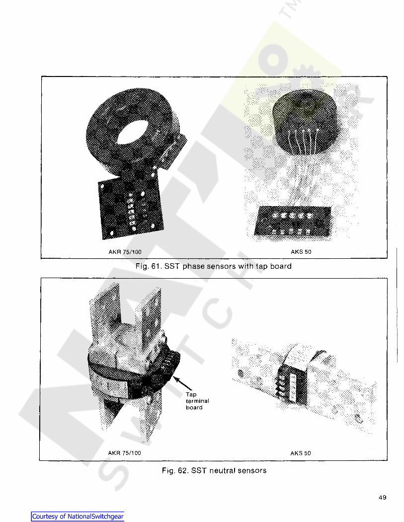
AKA 75/100 AKS 50
Fig. 61. SST phase sensors with tap board
Tapterminalboard
AKA 75/100
Fig. 62. SST neutral sensors
AKS 50
49

SECTION 8-Type SST Overcurrent Trip Device
1. Neutral sensorsecondary disconnect blockbreaker mounted
2. Equipmentmounted
Fig. 63. Neutral sensor secondary disconnect block
8.2.1-Replacement of CurrentSensors - AKS 50
Referring to Fig. 64, AKS50 phase sensors areremoved as follows:
a. Remove the connections to and the wiring harnessfrom the sensor tap board.
b. Remove the tap board retaining hardware.
c. Remove the lower connection strap.
d. Sensors are secured with RTV. Loosen RTV andremove sensors.
e. If the front and back frame have not been separated,replacement of the center pole sensor requires removal ofthe mechanism prop. Refer also to Fig. 24:
1. Remove retaining rings.
2. Disconnect spring.
3. Remove bearings
4. Remove prop.
50
1. Connection strap2. Bearing3. Retaining ring4. Prop
Fig. 64. Sensor replacement

1. Primary disconnects2. Tap board
Fig. 65. AKR 75/100 sensor replacement
8.2.2-Replacement of CurrentSensors - AKR 75/100
Referring to Fig. 65, the AKR 75/100 phase sensors areremoved as follows:
a. Disconnect the wiring harness and connections fromthe senser tap board.
b. Remove the tap board hardware.
c. Remove the primary disconnect assemblies from thestud.
d. Remove the sensor and tap board.
e. Reassemble in reverse order, align projections on rearof sensor with notches in the position ring which ismounted on the stud. Refer to Section 7.1.1 for torquerequirements for the primary disconnect hardware.
8.3-Flux Shift Trip DeviceThe Flux Shift Trip device is a low-energy, electromagneticdevice which, upon receipt of a trip signal from theprogrammer unit, trips the breaker by actuating the tripshaft.
The mounting arrangement of this component is illustratedin Figs. 66 and 67. An electromagnetic actuator located on
the underside of the front frame is coupled to the breaker'strip shaft via a trip rod driven by the actuator arm. Theactuator is a solenoid whose armature is spring-loadedand held in its normal (Reset) position by a permanentmagnet. In this state the spring is compressed.
So long as the actuator remains in the Reset position, thebreaker can be closed and opened normally at will.However, when a closed breaker receives a trip signal fromthe programmer unit, the actuator is energized and itssolenoid flux opposes the magnet, allowing the spring torelease the armature; this drives the trip rod against thetrip shaft paddle, tripping the breaker.
As the breaker opens, the actuator arm is returned to itsnormal (Reset) position via linkage driven by a crank onthe breaker's main shaft. The permanent magnet againholds the armature captive in readiness for the next tripsignal.
The trip device requires only one adjustment-the trip rodlength. As shown in Fig. 68, the clearance between the triprod end and the trip shaft paddle is gaged by a 0.109 inchdiameter rod. Adjust gap to 0.109 inch ± 0.031 inch. Toadjust, open the breaker and restore the breakermechanism to its Reset position. Loosen the jamb nut,rotate the adjuster end until the proper gap is attained,then retighten the jamb nut.
While operating the breaker, insure that the actuatorbracket does not interfere with the buffer stud. Adjust byloosening actuator bracket mounting screws and rotatingthe bracket clockwise to take up mounting hole slack.Retighten screws.
The actuator is a sealed, factory-set device and requires nomaintenance or field adjustment. In case of malfunction,the complete actuator unit should be replaced. Whenmaking the electrical connection to the replacement unit, itis recommended that the breaker harness be cut at someconvenient point and the new actuator leads solder-splicedthereto. An alternate method is to untie the breakerharness and remove the old actuator leads directly fromthe female AMP connector on the end of the breakerharness. However, AMP extraction tool Cat. No. 305183 isreq uired for this method.
CAUTION: IF THE BREAKER MUST CARRYCURRENT WITHOUT OVERCURRENTPROTECTION, THE SST TRIP DEVICE SYSTEMMUST BE PREVENTED FROM OPERATING.THE RECOMMENDED METHOD IS TO SHORTENTHE TRIP ROD BY TURNING ITS ADJUSTEREND FULLY CLOCKWISE. THIS PREVENTSACTUATION OF THE TRI~ SHAFT PADDLE.
51

SECTION 8-Type SST Overcurrent Trip Device
1. Actuator bracket2. Buffer stop3. Crossbar
Fig. 66. Flux shift trip device - linkage attachment
1. Actuator2. Actuator arm3. Trip rod4. Trip rod adjuster end5. Reset linkage6. Actuator bracket7. Mounting base
Fig. 67. Flux shift trip device with operating linkages
52

CROSSBAR'(BKR. OPEN)
ACTUATORBRACKET ---...........-t,..;
TRIP ROD109 IN "RESET"O. DIA.
ROD POSITIONADJUSTER
END
Fig. 68. Flux shift trip device adjustments
BUFFERSTUDPOSITION
Fig. 69. SST/ECS test set, cat. no. TAK-TS1
53

SECTION 8-Type SST Overcurrent Trip Device
8.4-TroubleshootingWhen malfunctioning is suspected, the first step introubleshooting is to examine the circuit breaker and itspower system for abnormal conditions such as:
a. Breaker tripping in proper response to overcurrentsor incipient ground faults.
b. Breaker remaining in a trip-free state due tomechanical interference along its trip shaft.
c. Inadvertent shut trip activations.
WARNING: DO NOT CHANGE TAPS ON THECURRENT SENSORS OR ADJUST THEPROGRAMMER UNIT SET KNOBS WHILETHE BREAKER IS CARRYING CURRENT.
o nee it has been established that the circuit breaker canbe opened and closed normally from the test position,attention can be directed to the trip device proper. Testingis performed by either of two methods:
1. Conduct high-current, single-phase tests on thebreaker using a high current-low voltage test set.
NOTE: For these single phase tests, specialconnections must be employed for SSTbreakers equipped with Ground Fault. Anysingle-phase input to the ground differentialtransformer will generate an unwanted "groundfault" output signal which will trip the breaker.This can be nullified either by
a. testing two poles of the breaker inseries, or
b. Using the Ground Fault Defeat Cable asshown in Fig. 73. This special test cableenergizes all the primary windings of thedifferential transformer in a self-cancelling,series-parallel connection so that its secondaryoutput is always zero.
2. Test the components of the SST system usingportable Test Set Type TAK-TS1 (Fig. 69). The applicabletest procedures are detailed in Instruction Book GEK64454 and are summarized in Section 8.4.1.
The TAK-TS1 Test Set is a portable instrument designedfor field checking the time-current characteristics andpickup calibration of the SST's various trip elements. It canverify the ability of the Flux-Shift Trip device to trip thebreaker and, in addition, includes means for continuitychecking the phase sensors.
54
8.4.1-55T Test 5etThe TAK·TS1 Test Set Is a portable instrument designed tofield·check time-current characteristics and pickup claibrationof the SST's trip elements. It can verify the ability of the Flux·Shift Trip Device to trip the breaker and includes means forcontinuity checking phase sensors.
WARNING: BEFORE CONNECTING TEST SET TOBREAKER TRIP DEVICE SYSTEM, ENSURE CIR·CUlT BREAKER IS COMPLETELY DISCONNECTED FROM ITS POWER SOURCE. ONDRAWOUT EQUIPMENT, RACK BREAKER TODISCONNECTED POSITION. VERIFY BREAKERIS TRIPPED.
Either of two test modes may be employed:
"A" - Programmer Unit Only. These tests are conductedwith the programmer unit disconnected from the breaker.During test, the unit can remain attached to the breaker ormay be completely removed from it.
CAUTION: NEVER DISENGAGE THE HARNESSCONNECTOR FROM THE PROGRAMMER UNIT ONA BREAKER ENERGIZED AND CARRYING LOADCURRENT. THIS WILL OPEN·CIRCUIT THE CUR·RENT SENSORS, ALLOWING DANGEROUS, DAMAG·ING VOLTAGES TO DEVELOP.
Test scope:
1. Verify the time-current characteristics and pickupcalibration of the various trip elements.
2. Verify operation of the SST target indicators onprogrammer units so equipped.
"B" - Complete Trip Device System. For these tests, theprogrammer unit must be mounted on the breaker andconnected to its wiring harness.
Test scope:
1. All "A" tests previously described, pius provision foroptionally switching the programmer's output to activatethe Flux-Shift Device and verify its operation by physicallytripping the breaker.
2. Check phase sensor continuity.
In the event that any component of the SST system doesnot perform within the limits prescribed in test instructionsGEK-64454, it should be replaced.

SECTION 8-Type SST Overcurrent Trip Device
8.4.2-Resistance ValuesFor use in troubleshooting, the Common to Tap resistancefor SST current sensors is given in Tables 9 and 10. Thesevalues apply to both phase and neutral sensors.
Table 9-Sensor Resistance ValuesAKS 50
Breaker Resistance in ohmsFrame Ampere between COMMONSize Tap and TAP Terminals
300 5.3-6.1400 7.2-8.2600 10.8-12.4
AKS-50 800 14.6-16.9
600 6.4-7.6800 8.8-10.4
1200 13.5-15.81600 19.4-22.8
800 10.2-12.0AKST-50 1200 15.8-18.6
1600 22.0-25.92000 28.5-33.6
Table 10-Sensor Resistance ValuesAKR 75/100
Resistance in ohmsTap Tap between COMMON
Breaker Terminal Lead terminal (white(AMP) Color lead) and TAP
terminal
1200 Black 13.4-15.7
AKR-75 1600 Yellow 18.3-21.52000 Red 23.5-27.63200 Green 42.1-49.5
1600 Black 18.3-21.6
AKR-100 2000 Yellow 23.5-27.63000 Red 37.7-44.34000 Green 53.4-62.6
The coil resistance of the SSTIECS Flux shifter device isapproximately 16 ohms.
8.4.3-False Tripping-BreakersEquipped with Ground Fault
When nuisance tripping occurs on breakers equipped withthe Ground Fault trip element, a probable cause is theexistence of a false "ground" signal. As indicated by thecabling diagram of Fig. 71 each phase sensor is connectedin a series with a primary winding on the Ground Faultdifferential transformer. Under no-fault conditions on 3wire load circuits, the currents in these three windings add
to zero and no ground signal is developed. This currentsum will be zero only if all three sensors have the sameelectrical characteristics. If one sensor differs from theothers (I.e., different rating or wrong tap setting), thedifferential transformer can produce output sufficient totrip the breaker. Similarly, discontinuity between anysensor and the programmer unit can cause a false tripsignal.
If nuisance tripping is encountered on any breaker whose SSTcomponents have previously demonstrated satisfactory performance via the TAK·TS1 Test Set, the sensors and their connections should be closely scrutinized after disconnecting thebreaker from all power sources.
a. Check that all phase sensors are the same type(ampere range).
b. Ensure that the tap settings on all 3-phase sensorsare identical.
8.5-SST Cabling Diagramsc. Verify that the harness connections to the sensors
meet the polarity constraints indicated by the cablingdiagram, I.e., white wire to COMMON, black wire to TAP.
d. On Ground Fault breakers serving 4-wire loads, checkthat the neutral sensor is properly connected (see cablingdiagram Fig. 72. In particular,
1. Verify that the neutral sensor has the same rating andtap setting as the phase sensors.
2. Check continuity between the neutral sensor and itsequipment-mounted secondary disconnect block. Alsocheck for continuity from the breaker-mounted neutralsecondary disconnect block through to the female harnessconnector (terminals Land N.).
3. If the breaker's lower studs connect to the supplysource, then the neutral sensor must have its LOAD endcon nected to the sou rce.
4. Ensure that the neutral conductor is carrying onlythat neutral current associated with the breaker's loadcurrent (neutral not shared with other loads).
e. If the preceding steps fail to identify the problem,then the sensor resistances should be measured. Since thephase and neutral sensors are electrically identical, theirtap-to-tap resistance should closely agree. See Table 9 orTable 10.
55

PROGRAMMERUNIT,------
AC
1 .....
PROGRAMMERCONNECTOR
(AMP 201297-1)
HARNESSCONNECTOR
(AMP 201298-1)
WHITE
t----'-'R=ED=---t~_<~+oB+- (48V. de)
~B~L~AC:<:.K~>+-<:H-o-+- (TO SCRE ANODE)
BLACK
FLUX SHIFTTRIP DEVICE
WHITE I'-+----1f---=:;B","LA.:.::C:.:.:K'----t-<>-t-« f-I-<>-I----' III
WHITE
LOAD
+A +B +C
AAABREAKER $ ~ $
BACK FRAME I-~, - b- b-: I~ r==)==-=!:'
LEFT POLE I lCURRENTSENSOR
Fig. 70. Cabling diagram-SST without ground fault
PROGRAMMERUNIT1------
D
F
A
C
HARNESSCONNECTOR PROGRAMMER
(AMP 201298-1) CONNECTOR(AMP 201297-1)
WHITE
WHITE
t----'-'==-+<:o+-<: H-o-+-o (48V de)
r-=~-+<>-t-<~~-O-+-o (TO SCRANODE)
WHITE
BLACK
BLACK
FLUX SHIFTTRIP DEVICE
LOAD
H
I,--_B::..:L::...A:.;::C.:..:.K_+c+-<: f-f-<K>-f--.
J
ttr
+A .B tC
AAABREAKER $ $ $
BACK FRAME 1 1, -b- b-: I
~ r==)===)=1LEFT POLE I ICURRENTSENSOR
Fig. 71. Cabling diagram-SST with ground fault on 3-wire load
56

PROGRAMMERUNIT,-----,
B IJ-'-'=-+O-J-< ~:....j...o4-e (48V. de) I
(TO SCR IE ANODE)
1 -'HARNESS
CONNECTOR PROGRAMMER(A CONNECTOR
MP 201298-1) (AMP 201297-1)
FLUX SHIFTTRIP DEVICE
I 'rl--+--t---t--+_...:.W~H!.!..!IT-=.E_-+-O-l-<4o-t--.
I I cA
, BLACK
II WHITEI A
I D INEUTRAL I BLACK FSENSOR I W
DISCONNECT I r+o-+-_-,-,-,-H,,-,IT-=.E_+<>+<~o-+--.
--1 I ~/ LINE I I BLACK ~i-I----.JIII
1\';r+~C:":::O~Mtoif7)+O+--+-l-~f-+-----:!..W:!.!:H!!..!ITE.E_-+O+-<~No.L.l----,t BLACK
~A ~B tC
AAAB:~~~~~~E r1-1-t-,~ )===)===)=
LEFT POLE ICURRENTSENSOR
1IIIL-...}o,,--,",,","--
liN
I
EQUIPM1NT'---M-O-UN-T-ED- r r t,NEUTRAL SENSOR \~---~v .
4-WIRE LOAD
Fig. 72. Cabling diagram-SST with ground fault on 4-wire load
ANY SSTPROGRAMMERUNIT WITHGROUND FAULTELEMENT
FEMALEEND
MALEEND
BREAKER PROGRAMMERHARNESS GROUND FAULT DEFEAT CABLE
CONNECTOR CAT. NO. TGFD UNITr \., .-- -"A~ \ f -- -,
~~~~6~~ i~~--O-+---ri---..-.c..-::.+-<: !~: ~$A F~-+--i~ : i ~:. 3 I
$B~~---L.-i~ : i ~ i' 3 ~$Ct I~ ~~
~ ~: 3NEU~ f-t-OISENSOR I~ ~I
DISCONNECT 0-+--< ~ IL_J L..----r--....J 1.._______ I L_ JL __ --.J
Fig. 73. Cabling diagram with ground fault defeat cable insertedbetween breaker harness and SST programmer unit-foruse during single-phase, high current-low voltage testing
57

SECTION 9-Type ECS Overcurrent Trip Device
The ECS is a solid-state, direct-acting, self-powered trip. device system. The ECS system consists of the ECSprogrammer unit shown in Fig. 74, current sensors, and aflux shifter trip device. Fig. 75 shows a block diagram ofthe system.
The ECS trip system essentially duplicates the SST tripsystem described in Section 8 except for the following:
1. Programmer units are limited to combinations ofLong Time, Short Time and Instantaneous trip elementsonly. The Ground Fault element is not available.
2. Fault indicators (trip targets) are not available.
3. Phase sensors are not tapped. As listed in Table 11each sensor has only a single ampere rating. A differentsensor is available for each of the tabulated ampereratings, which span the same range as SST, see Fig. 76.
4. Neutral sensors are not required because there is noGround Fault function.
In all other respects the ECS trip device system operatesand can be treated identically to SST. This includescircuitry, size, construction, component location,programmer unit set points, performance characteristics,operating range, quality, reliability and the flux shift tripdevice. Use the same troubleshooting and test proceduresfor single-phase, high current-low voltage tests or thoseemploying the TAK-TS1 Test Set. The Ground Fault testprocedures, of course, do not apply. ECS phase sensorresistance values are given in Table 12.
e
1j)----
Fig. 75. ECS block diagram
58
Fig. 74. ESC programmer unit
Fig. 76. ECS current sensor

Table 11-ECS Trip Characteristics
ECS PROGRAMMER ADJUSTMENT RANGE (Set Points)
Frame Long Time Short Time Instan-Breaker Size Sensor Pickup taneousFrame (Amperes) Ampere (L) Delay Pickup Delay PickupType Size Rating (Multiple Band (Multiple Band (MultipleType (Amperes) (X) of X) (Seconds) of L) (Seconds of L)
AKS-4/4A-50 1600300,400,600,800 .25, .3, A
1200, 1600 .5, .6, .7 (X)
AKST-4/4A-50 2000800, 1200, .2, .25, .3, A,1600, 2000 .5,.6 (X)
AK-4/4A-753000
1200,1600, Maximum 1.75, 2, MaximumAKR-4/4A-75 2000 3000 22 2.2~ 2.5, 0.35
1200,1600, .6, .7, .8, Intermed.3, (L)
Intermed. 4,5,6,AKR-4B/4C/4S-75 3200 2000,3000, .9, 1.0, 10 --or- 0.21 8, 10, 12 (L)
3200 1.1 (X)AK-l00 1600,2000, Minimum 3,4,5, Minimum
AKR-100400
3000 4000 4 6,8, 10 (L) 0.095
NOTES 1 • 3 • • •
, X= Sensor ampere rating = trip rating.2 Pickup tolerance = ± 10%
3 Time delay at lower limit of band @ 6L.• Time delay at lower limit of band.
9.1-ECS Cabling DiagramTable 12-Sensor Resistance Values
13.4-15.718.3 - 21.523.5 - 27.637.7 - 44.342.1 - 49.553.4 - 62.6
3.0 - 3.4404 - 5.04.8 - 5.66.4 - 7.26.7 - 7.8604- 7.68.8 - 10.4
13.5-15.81904 - 22.829.5 - 34.5
Resistance In OhmsBetween Terminals
120016002000300032004000
100150225300400600800
120016002000
AmpereRating
AKS50AKS750
BreakerTypePROGRAMMER
UNIT1------
\1_- --'PROGRAMMERCONNECTOR
(AMP 201297-1)
~R~ED~~-<~~B~(48V.de)
~B,,-,=L~AC~K4--<:>+-<~~-<>-+.... (TO SCRE ANODE)
HARNESSCONNECTOR
(AMP 201298-1)
WHITE
WHITE
WHITE
BLACK
BLACK
BLACK
FLUX SHIFTTRIP DEVICE
rrrLOAD
,A ,B ,CAAA
BREAKER ~ ~ ~BACK FRAME r~, - b- b:-:~ )===)===)=
LEFT POLE I 1CURRENTSENSOR
Fig. 77. Cabling diagram for ECS trip device
59
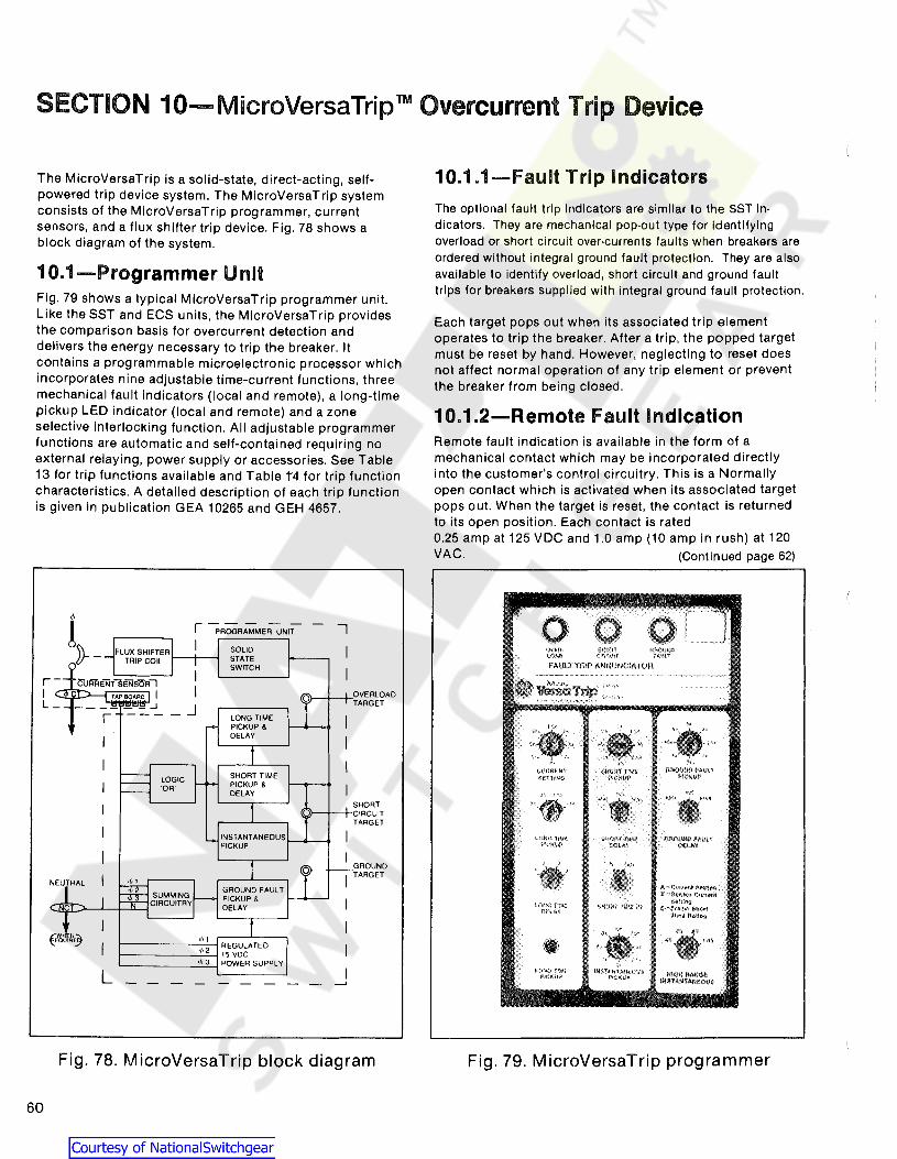
SECTION 10-MicroVersaTrip TM Overcurrent Trip Device
The MicroVersaTrip is a solid-state, direct-acting, selfpowered trip device system. The MicroVersaTrip systemconsists of the MicroVersaTrip programmer, currentsensors, and a flux shifter trip device. Fig. 78 shows ablock diagram of the system.
1O.1-Programmer UnitFig. 79 shows a typical MicroVersaTrip programmer unit.Like the SST and ECS units, the MicroVersaTrip providesthe comparison basis for overcurrent detection anddelivers the energy necessary to trip the breaker. Itcontains a programmable microelectronic processor whichincorporates nine adjustable time-current functions, threemechanical fault indicators (local and remote), a long-timepickUp LED indicator (local and remote) and a zoneselective interlocking function. All adjustable programmerfunctions are automatic and self-contained requiring noexternal relaying, power supply or accessories. See Table13 for trip functions available and Table t4 for trip functioncharacteristics. A detailed description of each trip functionis given in publication GEA 10265 and GEH 4657.
10.1.1-Fault Trip Indicators
The optional fault trip Indicators are similar to the SST indicators. They are mechanical pop-out type for identifyingoverload or short circuit over-currents faults when breakers areordered without Integral ground fault protection. They are alsoavailable to identify overload, short circuit and ground faulttrips for breakers supplied with integral ground fault protection.
Each target pops out when its associated trip elementoperates to trip the breaker. After a trip, the popped targetmust be reset by hand. However, neglecting to reset doesnot affect normal operation of any trip element or preventthe breaker from being closed.
1O.1.2-Remote Fault IndicationRemote fault indication is available in the form of amechanical contact which may be incorporated directlyinto the customer's control circuitry. This is a Normallyopen contact which is activated when its associated targetpops out. When the target is reset. the contact is returnedto its open position. Each contact is rated0.25 amp at 125 VDC and 1.0 amp (10 amp in rush) at 120VAC. (Continued page 62)
1»-_
NEUTRAL
I
II
SHORT,vr----.-----.- CIRCU IT
TARGET
GROUND)}-+--ITARGET
Fig. 78. MicroVersaTrip block diagram
60
Fig. 79. MicroVersaTrip programmer

Table 13-Trip Functions AvailableOptional Features
BASIC FUNCTIONS ADD TO BASIC FUNCTIONS
STD.-or-S-or-H-or-M L T G-or-GR A 1-or-A2-or-A3-or-A Zl-or-Z2-or·Z
• Adjustable Currenl Selling X X X X I I
• Adj Long-Time Pickup X X X X I I
LONG • Adj Long-Time Delay X X X XTIME • Long-Time Timing Light X X X X
• Remote Long-Time Timing Light X• Adj Short-Time Pickup X X X
SHORT • Adj Short-Time Delay X X XTIME • Short-Time I't Switch(j) XINSTANTA- • Adj Instantaneous Pickup X XNEOUS • Adj High Range Instantaneous X
• Adl Ground Fault PickupGROUND --1 Ph. 2-W-3 PH. 3-W X I I
IFAULT -Ground Return X• Ad] Ground Fault Delay X X• Tnp Indication Targets
-Overload & Short CircUit
I IOTHER -local only XFUNCTIONS -local and remote X
-0 L. S C and Ground FaultI
-local only (2l X-local and remote r X
• Zone Selective Interlock
I X-Ground Faultq) X-Short Tlme(j) X X
1 Shan-Time Delay IS required2 Standard when Ground Fault specified3 Ground Fault required
Table 14-MicroVersaTripTM Trip Characteristics
Lonq-Time Short-time Ground FeultCurrent AdjustableSetting Instantaneous Pickup
(X) (X) (MUltiple Pickup Pickup Pickup Short-time (MultipleFixed Tapped of Sensor (Multiple Delay (Multiple Delay (MUltiple 1'1 of sensor Delay
Maximum Sensors Sensors Current of Current (j) of Current ® of Sensor <D Current ®Freme Retlng Rating) Rating) (Seconds) Rating) (Seconds) Retlng) (Seconds) Rating) (Seconds)Size (Amps) Sensor Current Rating (X) (C) (C) (X) (X)
(Amps)
100. 150.100,150. 225.300 .5..6..7. .B,9, 25.5, 1.5,2,25. 0.10. 1.5,2.2.5, .2. 25..3, 0.10.0.22.
AKR-30 BOO 225,300, or .B, .B5.9, 1.0.11 10,21 3,4.5,7, 0.22. 3.4,6. B, OA 35. A, A5. 036400.600, 300.400 .95, 1.0 (C) 9 (C) 036 10 (X) 5..6 (X)
BOO 600. BOO (XI
300.400.300.400. 600. BOO
AKR-50 1600 600, BOO or "AKS-50 1200,1600 600. BOO
1200.1600
AKST-50 BOO, 1200. BOO. 1200AKRT-50 2000 1600.2000 1600,2000
1200.1600, 1200. 1600 .2..22, .24,AKR·75 3200 2000.3200 2000,3200 .26..2B..30. "
.34..37 (X)
1600.2000. 1600,2000 1.5, 2, 2.5, 3, .2..22..24.AKR·IOO 4000 3000,4000 3000. 4000 " " 4,5.7.9 (XI " .26, .2B..3 (X)
1 Time delay shown al 600% of ampere setting al lower limit 01 each band.2 Time delay shown at lower limit of each band.
All pickup lolerances are ± 10%Ground Fault pickup not to exceed 1200 amperes
c ~ current settingX = sensor OJrrent
61

SECTION 10-MicroVersaTripTM Overcurrent Trip Device
10.1.2-(Cont.)The remote fault indication switch leads are brought outthe bottom of the MicroVersaTrip programmer as shown inFig. 80. This switch lead harness is plugged into themating connector on the breaker, see Fig. 81.
The switch leads are brought out from the breaker throughthe Programmer Secondary Disconnect shown in Fig. 82.The zone selective interlocking function wiring is alsobrought out through this disconnect. See Figs. 76 and 77for the remote fault indication and zone selectiveinterlocking cable diagrams.
iJ
1. Remote fault indicatordisconnect
Fig. 81. Remote fault indicator disconnect
Fig. 80. MicroVersaTrip w/remote faultindication harness
Fig. 82. Programmer secondary connector
62
10.2-MicroVersaTrip InstallationThe programmer is located on the left side of the breaker'scenter channel as shown in Fig. 81. It mounts to thebracket assembly shown in Figs. 83 or 84. Referring toeither Fig. 83 or 84, the guide pins mate with the holes oneither side of the programmer, connector. They provide thenecessary alignment for the connector engagement. Thelocking lever engages with the pin which is assembled tothe programmer frame and secures the programmer to themounting bracket.
10.2.1-AKS 50 InstallationThe AKS 50 mounting bracket is shown in Fig. 83.Installation is as follows:
a. Insert the guide pins into the holes and push on theprogrammer. This will engage the connectors and releasethe locking lever which will move upwards.

b. Verify that the locking lever did engage theprogrammer pin.
c. Connect remote fault indication harness, if equipped,see Fig. 81.
To remove the programmer:
a. Disconnect remote fault indication harness, ifequipped.
b. Move locking lever to horizontal position, releasingprogrammer pin.
c. Remove programmer.
10.2.2.-AKR 75/100 InstallalionThere are two programmer mounting designs in use. Thedifference in the designs is in the operation of the lockinglever, see Fig. 84.
ORIGINALDESIGN
LATERDESIGN
1. Guide pin2. Locking/lever disengaged position3. Engaged position
Fig. 83. AKS 50 programmer mounting
Fig. 84. AKR 75/100 program mermounting
Installation using each design is as follows:
a. Insert the guide pins into the holes and push on theprogrammer, engaging the connectors.
b. Original design-push in the locking lever, securingthe programmer.
Later design-the locking lever is released, securingthe programmer.
c. Verify that the locking lever did engage theprogrammer pin.
d. Connect remote fault indication harness, if equipped,see Fig. 81.
To remove the programmer:
a. Disconnect the remote fault indication harness,if equipped.
(continued next page)
63
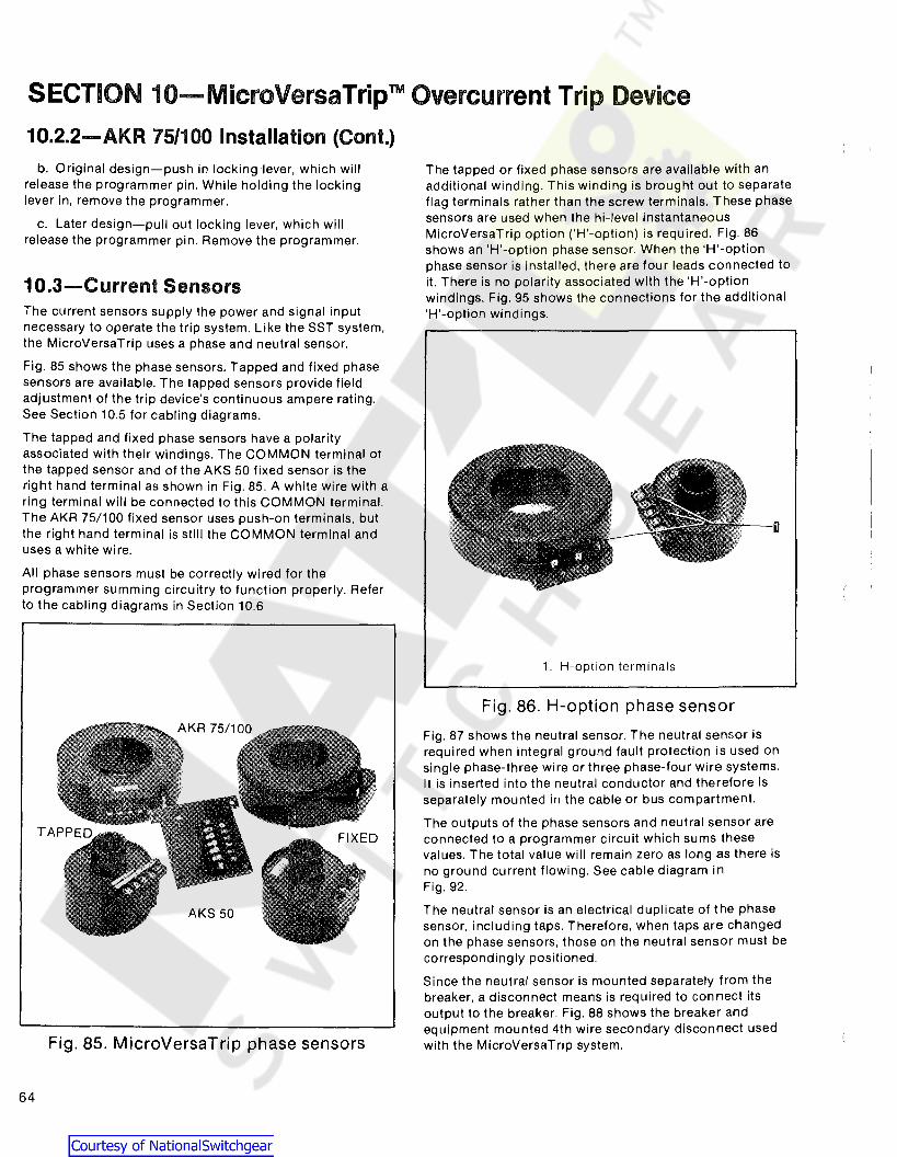
SECTION 10-MicroVersaTripTM Overcurrent Trip Device
10.2.2-AKR 75/100 Installation (Cont.)
b. Original design-push in locking 1ever, which willrelease the programmer pin. While holding the lockinglever in, remove the programmer.
c. Later design-pullout locking lever, which willrelease the programmer pin. Remove the programmer.
10.3-Current SensorsThe current sensors supply the power and signal inputnecessary to operate the trip system. Like the SST system,the MicroVersaTrip uses a phase and neutral sensor.
Fig. 85 shows the phase sensors. Tapped and fixed phasesensors are available. The tapped sensors provide fieldadjustment of the trip device's continuous ampere rating.See Section 10.5 for cabling diagrams.
The tapped and fixed phase sensors have a polarityassociated with their windings. The COMMON terminal Of
the tapped sensor and of the AKS 50 fixed sensor is theright hand terminal as shown in Fig. 85. A white wire with aring terminal will be connected to this COMMON terminal.The AKR 75/100 fixed sensor uses push-on terminals, butthe right hand terminal is still the COMMON terminal anduses a white wire.
All phase sensors must be correctly wired for theprogrammer summing circuitry to function properly. Referto the cabling diagrams in Section 10.6
Fig. 85. MicroVersaTrip phase sensors
64
The tapped or fixed phase sensors are available with anadditional winding. This winding is brought out to separateflag terminals rather than the screw terminals. These phasesensors are used when the hi-level instantaneousMicroVersaTrip option ('H'-option) is required. Fig. 86shows an 'H'-option phase sensor. When the 'H'-optionphase sensor is installed, there are four leads connected toit. There is no polarity associated with the 'H'-optionwindings. Fig. 95 shows the connections for the additional'H'-option Windings.
iI
1. H-option terminals
Fig. 86. H-option phase sensor
Fig. 87 shows the neutral sensor. The neutral sensor isrequired when integral ground fault protection is used onsingle phase-three wire or three phase-four wire systems.It is inserted into the neutral conductor and therefore isseparately mounted in the cable or bus compartment.
The outputs of the phase sensors and neutral sensor areconnected to a programmer circuit which sums thesevalues. The total value will remain zero as long as there isno ground current flowing. See cable diagram inFig. 92.
The neutral sensor is an electrical duplicate of the phasesensor, including taps. Therefore, when taps are changedon the phase sensors, those on the neutral sensor must becorrespondingly positioned.
Since the neutral sensor is mounted separately from thebreaker, a disconnect means is required to connect itsoutput to the breaker. Fig. 88 shows the breaker andequipment mounted 4th wire secondary disconnect usedwith the MicroVersaTrip system.

Fig. 87. Typical neutral sensor
10.3.1-Replacement of CurrentSensors - AKS 50
The replacement of the AKS 50 MicroVersaTrip currentsensors follows the same procedure used for the SSTsensors described in Section 8.2.1. The only difference isthat the tap board is not a separate item but is integral withthe sensor.
TYPICAL AKR 75/100-AKS 50 REAR MOUNTING
10.3.2-Replacement of CurrentSensors - AKR 75/100
The replacement of the AKR 75.100 MicroVersaTripcurrent sensors follows the same procedure used for theSST sensors, refer to Section 8.2.2
10.4-Flux Shifter Trip DeviceThe only difference between the MicroVersaTrip and SSTflux shifter trip devices is the solenoid winding. Refer toSection 8.3 for details.
When replacing a MicroVersaTrip flux shifter, AMPextraction tool Cat. No. 455822-2 is required to remove thesocket leads from the AMP connector.
10.5-TroubleshootingWhen malfunctioning is suspected, the first step introubleshooting is to examine the circuit breaker and itspower system for abnormal conditions such as:
a. Breaker tripping in proper response to overcurrentsor incipient ground faults.
b. Breaker remaining in a trip-free state due tomechanical interference along its trip shaft.
c. Inadvertent shunt trip activations.
WARNING: DO NOT CHANGE TAPS ON THECURRENT SENSORS OR ADJUST THEPROGRAMMER UNIT SET KNOBS WHILETHE BREAKER IS CARRYING CURRENT.
EQUIPMENT MOUNTED MATING DISCONNECT
Fig. 88. Neutral sensor secondary disconnect
65

SECTION 10-MicroVersaTriprM Overcurrent Trip Device
10.5--(Cont.)Once it has been established that the circuit breaker canbe opened and closed normally from the test position,attention can be directed to the trip device proper. Testingis performed by either of two methods:
1. Conduct high-current, single-phase tests on thebreaker using a high current-low voltage test set.
NOTE: For these single-phase tests, specialconnections must- be employed forMicroVersaTrip breakers equipped with GroundFault. Any sing Ie-phase input to theprogrammer circuit will generate an unwanted"ground fault" output signal which will trip thebreaker. This can be nullified either by
a. Testing two poles of the breaker in series,or
b. Using the Ground Fault Defeat Cable asshown in Fig. 94. This special test cableenergizes the programmer circuit in a selfcancelling, series-parallel connection so that itsoutput is always zero.
2. Test the components of the MicroVersaTrip systemusing portable Test Set Type TVS1 (Fig. 89). Theapplicable test procedures are detailed in instruction BookGEK-64464.
Fig. 89. Test set, cat. no. TVTS1
10.5.1-Resistance ValuesFor use in troubleshooting the MicroVersaTrip currentsensors, the resistance of the tapped and fixed windings isgiven in Tables 15 and 16 respectively.The coil resistance of the MicroVersaTrip flux shifterdevice is approximately 7 ohms.
66
Table 15-Tapped SensorResistance Values
Breaker Resistance In ohmsFrame Ampere between CommonSize Vap 2nd Tap Terminals
300400600800
AKS50600800
12001600
8001200 CONSULT
AKST50 1600 FACTORY2000
AKR75 1200160020003200
1600AKR100 2000
30004000
Table 16-Fixed SensorResistance Values
Breaker Resistance In ohmsFrame CT between CommonSize Rating 2nd Tap Terminals
300400600
AKS50 80012001600
800AKST50 1200
16002000 CONSUL T
FACTORY1200
AKR75 1600200030003200
1600AKR100 2000
30004000

10.6-MicroVersaTrip CablingDiagrams
28
PROGRAMMERUNIT
1------32RED
WHITE
\1_- -'c~~~~~~gR PROGRAMMER
(AMP '-350356-9) CONNECTOR
FLUX SHIFTTRIP DEVICE
LOADrrr
OA oB OC
AAAB~~;~~~~E 11-1-t- i~ r=+=:)=
LEFT POLE f I~~%~~NRT ,'-.J':::'O::':c:+--+---+----+-<>-K.E-+<''"'8f--o
I ~ 22
'II A
IIIII
I
1-
1O.5.2-False Tripping-BreakersEquipped with Ground Fault
When nuisance tripping occurs on breakers equipped withthe Ground Fault trip element, a probable cause is theexistence of a false "ground" signal. As indicated by thecabling diagram of Fig. 91, each phase sensor isconnected to summing circuitry in the programmer. Underno-fault conditions on 3-wire load circuits, the currents inthis circuitry add to zero and no ground signal isdeveloped. This current sum will be zero only if all threesensors have the same electrical characteristics. If onesensor differs from the others (I.e., different rating orwrong tap setting), the circuitry can produce outputsufficient to trip the breaker. Similarly, discontinuitybetween any sensor and the programmer unit can cause afalse trip signal.
If nuisance tripping is encountered on any breaker whoseMicroVersaTrip ~ components have previously demonstratedsatisfactory performance via the TVTS1 Test Set, the sensorsand their connections should be closely scrutinized afterdisconnecting the breaker from all power sources.
Fig, 90. Cabling diagram-MicroVersaTripwithout ground fault
Fig. 91. Cabling diagram-MicroVersaTripwith ground fault on 3-wire load
17
28
1923
2024
1822
L ....PROGRAMMERCONNECTOR
PROGRAMMERUNIT
- 1-----1RED 32 I
I-W-!:H~'T~E+O-+-<~>-t-- II
FLUX SHIFTTRIP DEVICE
LOAD
II I'------1-0+-< ~t-<>-t-
,_ J
'fr.
oA oB .c
AAABREAKER ,-.$--$-4'-,
BACK FRAME I ~, b b. I~ r==)===}.o
LEFT POLE I ICURRENTSENSOR
3. If the breaker's lower studs connect to the supplysource, then the neutral sensor must have its LOAD endconnected to the source. See Fig. 93.
4. Ensure that the neutral conductor is carrying onlythat neutral current associated with the breaker's loadcurrent (neutral not shared with other loads).
e. If the preceding steps fail to identify the problem,then the sensor resistances should be measured. Since thephase and neutral sensors are electrically identical, theirtap-to-tap resistances should closely agree. See Tables 15and 16.
a. Check that all phase sensors are the same type(ampere range).
b. Ensure that the tap settings on all 3-phase sensorsare identical.
c. Verify that the harness connections to the sensorsmeet the polarity constraints indicated by the cablingdiagram.
d. On Ground Fault breakers serving 4-wire loads, checkthat the neutral sensor is properly connected (see cablingdiagram Fig. 92). In particular,
1. Verify that the neutral sensor has the same rating andtap setting as the phase sensors,
2. Check continuity between the neutral sensor and itsequipment-mounted secondary disconnect block. Alsocheck for continuity from the breaker-mounted neutralsecondary disconnect block through to the female harnessconnector.
67

SECTION 10-MicroVersaTripTM Overcurrent Trip Device
IIIIIIIIIIIIIIIIIII1 ......
17
21
1822
2024
1923
28
PROGRAMMERUNIT,-----,
RED 32 I~=--t-<>+-<f+C>-i I
WHITE
HARNESSCONNECTOR PROGRAMMER
AMP 1-350356-9 CONNECTOR
FLUX SHIFTTRIP DEVICE
+A +B 'cAAA
BREAKER r$ --$-4'- IBACK FRAME ~,b b, I~ )===)===)=
LEFT POLE ICURRENTSENSOR
'111
EQUIPMENT-MOUNTED \ '( r rNEUTRAL SENSOR L---~v
4-WIRE LOAD
Fig. 92. Cabling diagram-MicroVersaTrip with ground fault on 4-wire load
4-WIRE LOAD
1822
28
PROGRAMMERUNIT,-----,
RED 32 It--'-=--t-o+<. f+<H IWHITE
1 ......
HARNESSCONNECTOR PROGRAMMER
AMP 1-350356-9 CONNECTOR
FLUX SHIFTTRIP DEVICE
r-__~A,- ~
,111 'BREAKER r $ --$- 4'- I
BACK FRAME ~,b ~,I
~ )===)===rLEFT POLE ICURRENTSENSOR
:tI,I A
INEUTRAL ISENSOR I
DISCONNECT I
~-1 I
EQUIPMENT -MOUNTED I LOAD\ INEUTRAL SENSOR I COM
~{t"--++=-::~\ I N >+ot--i----t----t--+-----------t-<>-KH-C>-i
L
LOAD
Fig. 93. Cabling diagram-MicroVersaTrip with groundfault on 4-wire load-breaker reverse feed
68

SECTION 10-MicroVersaTripTMOvercurrent Trip Device
BREAKERHARNESS
CONNECTOR,r ...,
0-+--<0--+-<o--t--<0--+--<
0-+-<
o---r-<o-----t---<o-t-<o---t-<
0--+--<~
0-+-<o.--l-<cr-t-<o-t--<0--+-<0--+---<~
L J
GROUND FAULT DEFEAT MODULECAT, NO, TVTGD9
r----~A'---__~\
..-----~1~--
'g ~~ ~4 4
5 ~Q 27 7
8 :a18
019
2'P0
017
022 ??23 23
24 24
2j 26
;!~ 28
~ 3)/
- - --~ ~
PROGRAMMERUNIT
,---,,--1 I~I 1
~ I I~ I I
~: i~~ I I~I
~ I I1 0 I I ANY MICROVERSATRIPI 0 I I PROGRAMMERI () UNIT WITH
I I GROUND FAULTI 0 I ELEMENT
~I I~ I I4-u I I~+-o I I~I
~J I IL --l 1
L __ -l
Fig. 94. Cabling diagram with ground fault defeat module inserted betweenbreaker harness and MicroVersaTrip programmer unit-for useduring single-phase, high current-low voltage testing
----~
PROGRAMMERUNIT1------
PROGRAMMERCONNECTOR
HARNESSCONNECTORrry
r- - - -I r- '13I)===)===)=1
I I E
I YELLOW
:t~ I 14I YELLOW 10
II -I A I YELLOW
I t~, 15
YELLOW 11I I:~ f-<>- ......
I IB I YELLOW:f-~
......f H II YELLOW
/12
I IC1_ _ ___ I-.J ......,,,1/ '\l/ ,,1/
BREAKERBACK FRAME
~Partial
LEFT POLECURRENTSENSOR
LOAD
Fig. 95. Partial cabling diagram: 'H'-option winding connections
69

SECTION 10-MicroVersaTripTM Overcurrent Trip Device
PROGRAMMER REMOTE FAULT MICROVERSATRIPSECONDARY INDICATION PROGRAMMERDISCONNECT CONNECTOR
EQUIPMENT BREAKER------
9 9 IYELLOW I
OVERLOAD { YELLOWI
RED ISHORT {CIRCUIT RED I13 13 GREEN IGROUND J 14 14 GREEN IFAULT toE15 15 BLUE I
OVERLOAD f 16 16 BLUE IPICKUP 1 II------~
AMP AMP AMP AMP1-350239-9 1-350246-9 1-350242-9 1-350235-9
Fig. 96. Cabling diagram-remote fault indication
PROGRAMMERSECONDARYDISCONNECT
EQUIPMENT BREAKER
PROGRAMMERHARNESS
CONNECTOR
MICROVERSATRIPPROGRAMMER--I
--~AMP
1-350246-9AMP
1-350239-9
SHORT TIME { +
OUTPUT - <E'----f--CH--< ~_+_<)-t------H)+--<.
SHORT TIME { ~
INPUT - <E'----K.>-+--< <E'---_+_<J-t------t-
GROUND FAULT { +
OUTPUT - ~-I-Cr+--< ~+(}-+ -+-(
GROUND FAULT { +
INPUT _ <C---H.:)+--< ~+<}-f------+-
Fig. 97. Cabling diagram-zone selective interlock
70

71
Note Locationof Pin #1
FIG. 99RMS-9 & Epic MicroVersaTrip
Programmer
FIG. 100Programmer Secondary
Connector Epic MicroVersaTrip
SECTION 11-RMS-9/Epic MicroVersaTripTMThe RMS-9/Epic MicroVersaTrip is a solid-state, direct-acting, self-powered trip device system. The RMS-9 systemconsists of the RMS-9 programmer, current sensors, and aflux shifter trip device. Fig. 98 shows a block diagram of thesystem.
11.1-Programmer UnitFig. 99 shows a typical RMS-9Epic MicroVersaTrip unit.The RMS-9/Epic MicroVersaTrip provides the comparisonbasis for overcurrent detection and delivers the energy necessary to trip the breaker. It contains a programmable microelectronic processor which incorporates nine adjustabletime-current functions, three mechanical fault indicators, along-time pickup LED indicator and a zone selective interlocking function. All adjustable programmer functions areautomatic and self-contained requiring no external relaying,power supply or accessories. See Table 17 for trip functionsavailable and Table 18 for trip function characteristics. A detailed description of each trip function is given in publicationGEK 97367.
OA-{~AMPLIFIER
XFMRN---L}--~~~-,
os----EJR8~ RATING PLUG ~~~;C~':STE
OCL~Jl~! r~c~L~'ER ~; TRIP
~1.. ;RATING PLUG ST
COMPARATOR TO
--+ ~ C~ '<2Cr,RIP 'FLUXINST~ SHIFTERSWITCH
Fig. 98. RMS-9 Block Diagram11.1.1-Fault Trip IndicatorsThe optional fault trip indicators are similar to theMicroVersaTrip indicators. They are mechanical pop-outtype for identifying overload or short circuit over-currentfaults when breakers are ordered without integral groundfault protection. They are also available to identify overload,short circuit and ground fault trips for breakers supplied withintegral ground fault protection.
Each target pops out when its associated trip elementoperates to trip the breaker. After a trip, the popped targetmust be reset by hand. However, neglecting to reset doesnot affect normal operation of any trip element or preventthe breaker from being closed.
11.2-RMS-9 & Epic MicroVersaTripInstallation
The programmer mounts to the lower left of the breakeras shown in Fig. 101. It mounts to the bracket assemblyshown in Fig. 82. Referring to Fig. 82, the guide pins matewith the holes on either side of the programmer connector.They provide the necessary alignment for the connectorengagement. The locking lever engages with the pin whichis assembled to the programmer frame and secures the programmer to the mounting bracketInstallation using each design is as follows:a. Insert the guide pins into the holes and push on the programmer, engaging the connectors.b. The locking lever is released, securing the programmer.c. Verify that the locking lever did engage the programmer ·pin.To remove the programmer:a. Pull out locking lever, which will release the programmerpin. Remove the programmer.

SECTION 11-RMS-9 and Epic MicroVersaTrip ™ Trip Device
11.3-Current SensorsThe current sensors supply the power and signal input necessary to operate the trip system. The RMS-9 and EpicMicroVersaTrip") use a phase and neutral sensor. Fig. 102shows the phase sensors. See Section 11.5 for cabling diagrams.
Fig. 101
The fixed phase sensors have a polarity associated with theirwindings. Their COMMON terminal is the right hand terminalas shown in Fig. 102. A white wire with a push on terminalwill be connected to this COMMON terminal. All phase sensors must be correctly wired for the programmer summingcircuit to function properly.
The phase sensors are available with an additional winding.This winding is brought out to separate flag terminals. Thesephase sensors are used when the hi-level instantaneousRMS-9 option ('H'-option) is required. Fig. 102 shows an'H'-option phase sensor. When the 'H'-option phase sensoris installed, there are four leads connected to it. There is nopolarity associated with the special winding connection. Fig.103 shows the connections for the additional 'H'-optionWindings.
72

TABLE 17. TRIP FUNCTIONS AVAILABLE
Optional Features
BASIC FUNCTIONS ADD TO BASIC FUNCTIONS
STD.-or-8-or-H-or-M L T G-or-GR A1-or-A2-or-A3-or-A Z1-or-Z2-or-Z• Adjustable Current Selting X X X X• Adj Long-Time Pickup X X X X
LONG • Adj Long-Time Delay X X X XTIME • Long-Time Timing Light X X X X
• Remote Long-Time nming Light X• Adj Short-Time Pickup X X X
SHORT • Adj Short-Time Delay X X XTIME • Short-Time 12t Switch <D XINSTANTA- • Adi Instantaneous Pickup X XNEOUS • Adj High Range Instantaneous X
• Adj Ground Fault PickupGROUND -1 PH, 2·W-3PH, 3/4-W XFAULT -Ground Return X
• Adj Ground Fault Delay X X• Trip Indication Targets
-Overload & Short CircuitOTHER -local only XFUNCTIONS -local and remote X
-OIL, SIC and Ground Fault-local only(2) X-local and remote X
• Zone Selective Interlock-Ground Fault~ X X-Short Time<D X X
1 Short·Time Delay is required2 Standard wnen Ground Fault specified3 Ground Fault required
TABLE 18. MICROVERSATRIP" TRIP CHARACTERISTICSLong-Time Short·Time
Adjustable AdjustableGround Fault
Current Instantan- Instantan~ High RangeSetting eous eous Instantan- Triple Pickup(Mult. Pick up Pick up Pick Up Pick Up eous Selective (Mult.
of (Mult. (Mult. w/o ST withST (Mult. of Trip ofSensor Rating of of (Mult. of (Mult. of Frame Fixed High Sensor
Max. Rating Plug Current Current Rating Rating Short-time Range Amp Delay Delay'"Frame Amp (Amps) Amps) Setting} Delay' Setting} Delay Plug Amps) Plug Amps) Rating) Instantaneous Rating) w/I'T w/o I'TSize Rating (s) (Xl (C) (Sec.) (C) (Sec.) (X) (X) (HI 5 (5) (Sec.) (Sec.)
.2, .22,.5, .6, Fixed at .24,
.44 atAKR-75 3200 3200 .7, .8, 1.0 of 2.4,4.9, 12T in: 1 1.5,2,3,5, 1.5.2,3,5, .4, .6, .8, 1.0 NA .26,
200%.10, .21,
.9, .95, Current 9.8,20 .40 7,9,10 7.9,10,13 .28, .351.0,1.1 Setting 1.5,2.0. .30, of pick
2.5.3.0, ['T .34, .37 up at4.0,5.0, out: 2
lower
.5, .6, Fixed al 7.0,9.0 .10, .2, .22, limitof
AKR-100 4000 4000 .7, .8. 1.0 of 2.4,4.9, .21,35 1.5,2,3,5, 1.5,2,3,5, .4, .6, .8, 1.0 NA .24,band
.10, .21,.9..95, Current 9.8,20 7,9 7,9 .26, .351.0,1.1 Setting .28, .3
:1 Time delay shown at 600% elfcurrent setting at lower limitof band.
Time delay shown at lowerlimit of each band. All pickup tolerances are ± 10%.
x=Rating plug ampsS =Sensor amp ratingC = Current setting
Triple selective trip isstandard when longtime/short-time onlyIS required.
'6; Time delay shown at lowerlimit of each band.Ground fault pick up notto exceed 1200 amps.
73
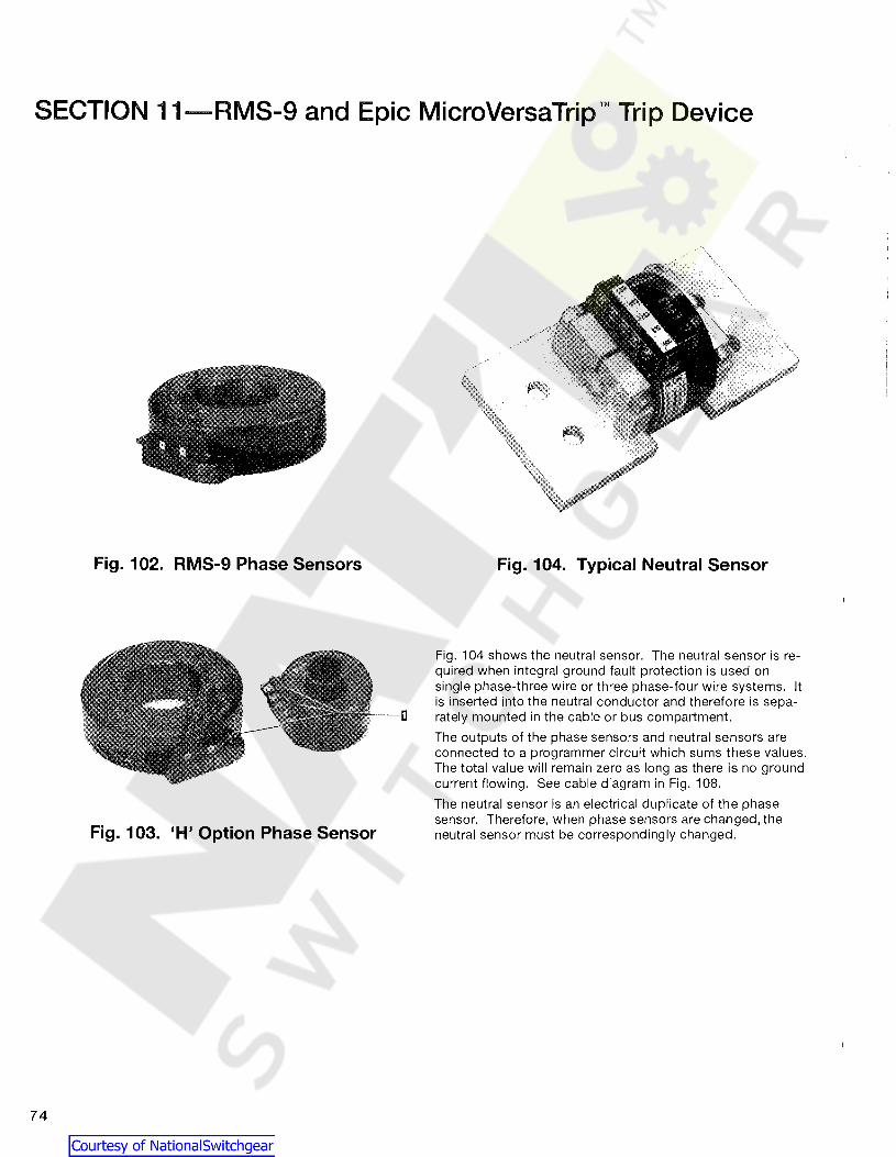
SECTION 11-RMS-9 and Epic MicroVersaTrip nl Trip Device
74
Fig. 102. RMS-9 Phase Sensors
Fig. 103. 'H' Option Phase Sensor
Fig. 104. Typical Neutral Sensor
Fig. 104 shows the neutral sensor. The neutral sensor is required when integral ground fault protection is used onsingle phase-three wire or three phase-four wire systems. Itis inserted into the neutral conductor and therefore is separately mounted in the cable or bus compartment.
The outputs of the phase sensors and neutral sensors areconnected to a programmer circuit which sums these values.The total value will remain zero as long as there is no groundcurrent flowing. See cable diagram in Fig. 108.
The neutral sensor is an electrical duplicate of the phasesensor. Therefore, when phase sensors are changed, theneutral sensor must be correspondingly changed.

Since the neutral sensor is mounted separatelyfrom the breaker, a disconnect means is required toconnect its output to the breaker. Fig. 88 shows thebreaker and equipment mounted 4th wire secondarydisconnect used with the RMS-9 system.
11.3.1-Replacement of CurrentSensors
Referring to Fig. 88, replacement of RMS-9 & EpicMicroVersaTrip® current sensors is accomplished by thesame procedure as the MicroVersaTrip® current sensors.
11.4-Flux Shifter Trip DeviceThe only difference between the RMS-9/EpicMicroVersaTrip® and the SST flux shifter trip devices is thesolenoid winding. Refer to Section 8.3 for details.
When replacing a RMS-9/Epic MicroVersaTrip® flux shifter,AMP extraction tool Cat. No. 455822-2 is required to removethe socket leads from the AMP connector.
11.5--TroubleshootingWhen malfunctionion is suspected, the first step in
troubleshooting is to examine the circuit breaker and itspower system for abnormal conditions such as:
a) Breaker tripping in proper response to overcurrents orincipient ground faults.
b) Breaker remaining in a trip-free state due tomechanical maintenance along its trip shaft.
c) Inadvertent shunt trip activations.
WARNING: DO NOT ADJUST THE PROGRAMMER UNIT(KNOBS) WHILE THE BREAKER IS CARRYING CUR-
Once it has been established that the circuit breakercan be opened and closed normally from the test position,attention can be directed to the trip device proper. Testingis performed by either of two methods:
1. Conduct high-current, single-phase tests on thebreaker using a high current-low voltage test set.
NOTE: For these single-phase tests, special connectionsmust be employed for RMS-9 breakers equipped withGround Fault. Any single-phase input to the programmer circuit will generate an unwanted "ground fault" output signalwhich will trip the breaker. This can be nullified either by
a) Using the Ground Fault Defeat Cable as shown inFig. 94 This special test cable energizes the programmer circuit in a self-cancelling, series-parallelconnection so that its output is always zero.
2. Test the components of the RMS-9 system using portableTest Set Type. The applicable test procedures are detailedin instruction Book 97367.
The time-current characteristics for the RMS-9 & EpicMicroVersaTrip Trip Device are given in curves GES-6227and GES-6228.
Fig. 105. Test Set, Cat. No. TVRMS11.5.1-Resistance ValuesFor use in troubleshooting the RMS-9 current sensors, theresistance of the fixed windings is given in Table 19.
TABLE 19.Ampere Resistance in OhmsRating Between Terminals
150 10-12400 27-32800 58-681600 129-1512000 207-243
The coil resistance of the RMS-9 & Epic MicroVersaTrip'" fluxshifter device is approximately 7 ohms.
75

SECTION 11-RMS-9 and Epic MicroVersaTripTM Trip Device
11.5.2-False Tripping-BreakersEquipped With Ground Fault
11.6-Cabling Diagrams
LOAD
Fig. 106. Cabling diagram-RMS-9 & EpicMicroVersaTrip without ground fault
28
PROGRAMMERUNIT1------
32
2024
28
PROGRAMMERUNIT1------
32
1 -'
PROGRAMMERCONNECTOR
\1_- -,PROGRAMMERCONNECTOR
RED
RED
( I
WHITE
WHITE
HARNESSCONNECTOR
(AMP 1-350356-9)
HARNESSCONNECTOR
(AMP 1-350356-9)
FLUX SHIFTTRIP DEVICE
FLUX SHIFTTRIP DEVICE
LOAD
rrr
J
rrr
cj>A cj>B .vBREAKERA A A~~;~E'f -1-t-i"": )= ==)= ==)=
LEFT I 1POLE
CURRENTI '-+---+--+--+-----+<:>-+-< ~t-<1)-8t-
SENSOR I t 22I I 4-<_+--I-+-----t-<>-t-<'E-+<>+I A
IIIII
I
1-
cj>A cj>B cj>c
BREAKER A A A~~~~E If -1-t- i~ )===)===)=
LEFT I IPOLE COM
CURRENTI ',.-1...:+:.4--+-+-----+0+<~t<1O-8~
SENSOR I t 22
I I 4-<..-+--1-+---I A
: +I..J-o--+-+-----+<::+<. ~-o~;-t-III
I
1-
a) Check that all phase sensors are the same type (ampere range).
b) Verify that the harness connections to the sensorsmeet the polarity constraints indicated by the cablingdiagram.
c) On Ground Fault breakers serving 4-wire loads,check that the neutral sensor is properly connected (seecabling diagram Fig.108). In particular,
(1) Verify that the neutral sensor has the same ratingas the phase sensors.
(2) Check continuity between the neutral sensor and itsequipment-mounted secondary disconnect block. Alsocheck for continuity from the breaker-mounted neutralsecondary disconnect block through to the female harnessconnector.
(3) If The breaker lower studs connect to the supplysource, then the neutral sensor must have its LOAD endconnected to the source. See Fig. 109.
(4) Ensure that the neutral conductor is carrying onlyth at neutral cu rrent associated with the breaker load current (neutral not shared with other loads).
e) If the preceding steps fail to identify the problem, thenthe sensor resistances should be measured. Since thephase and neutral sensors are electrically identical, theirtap-to-tap resistances should closely agree. See Table 19.
When nuisance tripping occurs on breakers equipped withthe Ground Fault trip element, a probable cause is the existence of a false "ground" signal. As indicated by the cablingdiagram of Fig. 106, each phase sensor is connected tosumming circuitry in the programmer. Under no-fault conditions on 3-wire load circuits, the currents in this circuitry addto zero and no ground signal is developed. This current sumwill be zero only if all three sensors have the same electricalcharacteristics. If one sensor differs from the others (i.e. different rating), the circuitry can produce output sufficient totrip the breaker. Similarly, discontinuity between any sensorand the programmer unit can cause a false trip signal.
If nuisance tripping is encountered on any breaker whoseRMS-9 or Epic MicroVersaTrip components have previouslydemonstrated satisfactory performance via the lVRMS TestSet, the sensors and their connections should be closelyscrutinized. After disconnecting the breaker from all powersources.
Fig. 107. Cabling diagram-RMS-9 & EpicMicroVersaTrip with ground fault on 3-wire load
76
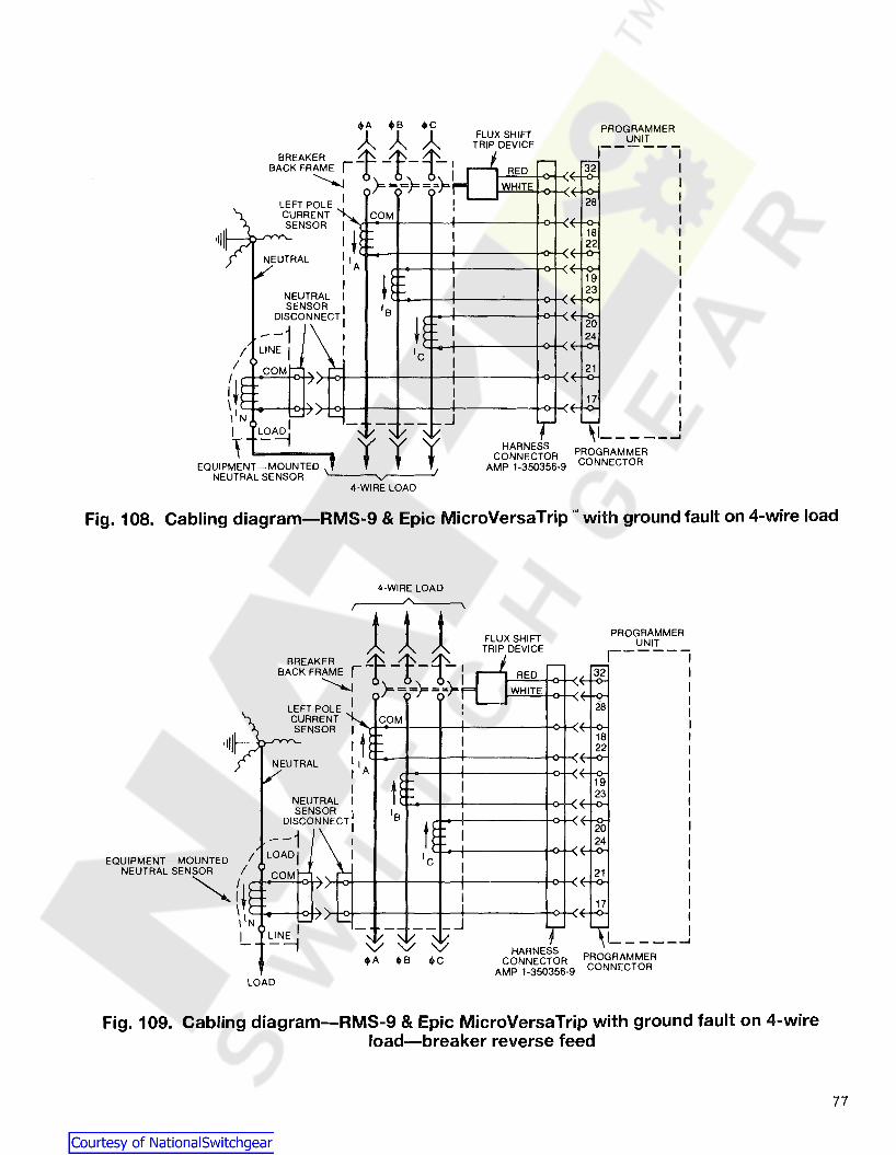
18~2
1923
28
PROGRAMMERUNIT1------
32
WHITE
RED
1 ......
HARNESSCONNECTOR PROGRAMMER
AMP 1-350356-9 CONNECTOR
FLUX SHIFTTRIP DEVICE
: ~I I I..I--_+--+--+-----~>+_<~_k>_I
I AI
NEUTRAL ISENSOR I
DISCONNECT I
--1 I
I LINE I II COM
(~ ";-'::=1-<>+7)-+o+--I---f---+-+----+o+<
\ L+_-kl-A.>+<>t--J--I----+~----+_O_I_<4:..+0-1liN
I ~A~
EQUIPM1NT-MOUNTED \ r r 1NEUTRAL SENSOR '---~V
4-WIRE LOAD
Fig. 108. Cabling diagram-RMS-9 & Epic MicroVersaTrip'· with ground fault on 4-wire load
4-WIRE LOAD
----- ......
PROGRAMMERUNIT,-----
HARNESSCONNECTOR PROGRAMMER
AMP 1-350356-9 CONNECTOR
FLUX SHIFTTRIP DEVICE111
~~E r1-1-t-~ RED -~32
~ »=. =rr =),}- I WHITEOLE I I J 28
ENT COM : ' ,OR I I~ 18
I t r-II 22
'I II A
RAL: H~ I 19
I 23
OR I IB INECT
I n ,~ -rc;I I
~~I I
CI :f-
! :f-~I
" - I 17L.... _J "- /-, /--...,
" ,/ I
LEFT PCURRSENS
LOAD
BREAKBACK FR
EQUIPMENT -MOUNTED INEUTRAL SENSOR I
~{~~+<>+'\\IN
L ~N~
Fig. 109. Cabling diagram-RMS-9 & Epic MicroVersaTrip with ground fault on 4-wireload-breaker reverse feed
77

SECTION 11-RMS-9 and Epic MicroVersaTripTM Trip Device
Socket
ClassNo.
5 +Gnd .Fault
Zone 6 - InputsSelectiveInterlock 7 +
Gnd. Fault8 - Outputs
11 -
12 + Commnet
9 Spare
Epic 10 VC
MVT1 V3
4 VA
2 24 Ret
3 + 24 VDC
Note Locationof Pin #1
Fig. 110. Programmer secondary connector pin locations for zoneselective interlock and Epic MicroVersaTrip Trip Device
78

SECTION 12-MicroVersaTripTM Plus andMicroVersaTripTM PM Trip Units
The MVT-Plus/MVT-PM is a solid-state, direct-acting, selfpowered trip device system. The system consists of theMVT-Plus/MVT-PM programmer current sensors and a fluxshifter trip device. Figure 111 shows location of features onprogrammer. See user manual GEH-5891 A.
12.1-Trip UnitMicroVersaTrip Plus Trip UnitMicroVersaTrip Plus trip units utilize a digital, LCD displaywith a four-button keypad to provide local set-up and readout of trip settings. A 3-phase ammeter and trip indicatorsare standard, as is a clear plastic cover with provisions forsealing to allow tamper resistant installation. The trip unitdigitally measures the current waveform in each phase to determine the true RMS value of the current, regardless of thewaveshape. MicroVersaTrip@ Plus trip units provide accurate, predictable overload and short circuit protection for distribution systems that include ac and dc variable speeddrives, rectifiers, induction heating, and other loads thatcause high harmonic distortion as well as standard circuit.They provide maximum breaker-to-breaker selectivity andcustom load protection. Short time and ground fault functions include the flexibility of coordination with or without an12t ramp and are also available with high range instantaneous.
MicroVersaTrip PM Trip UnitMicroVersaTrip PM trip unit adds power management system capability, advanced metering, and protective relays tothe basic functions of the MicroVersaTrip Plus.MicroVersaTrip PM trip units communicate directly on theGE POWER LEADER'" communications bus.
Power RequirementsA small amount of power is necessary to energize the liquidcrystal display (LCD) during setup, for viewing breaker status,and for metering displays. MicroVersaTrip PM trip units require external 24 Vdc control power for operation. The foursources of such power are the following.
• Flow of current - Breaker current sensors providesufficient power to energize the LCD when at least20% of the sensor's ampere rating is flowing.
• 24 Vdc control power - Breakers with MicroVersaTripPM trip units are supplied with external 24 Vdc powerthat, whenever present, energizes the LCD. Somebreaker models that are configured forMicroVersaTrip Plus trip units may be optionallyequipped to accept an external 24 Vdc supply.
• MicroVersaTrip Test Kit - The MicroVersaTrip TestKit, Cat. No. TVRMS, contains a 24 Vdc power supply. The LCD is energized whenever the test kit jackis plugged into the test receptacle on the rating plug.
• MicroVersaTrip battery pack - The portableMicroVersaTrip battery pack contains a 24 Vdcpower source and a jack. The LCD is energized whenthe jack is plugged into the rating plug test receptacle.
MicroVersaTrip PM Trip Unitfor Metering, Relaying, and Communication on
AKR Power Circuit Breakers
SELECT Keychooses next itemfor display
ENTER Keystores options
VALUE Keyselects phase todisplay or altersetpoint values
Interchangeablerating plug forflexibility in matchingload requirements
LCD readout formetered values, tripsettings, and fault tripindication
FUNCTION Keyselects the modeof display
79
Fia. 111

SECTION 12-MicroVersaTrip ™ Plus andMicroVersaTrip PM Trip Units
12.2-TestingTesting of MicroVersaTrip Plus and MicroVersaTrip PM tripunits may be performed with the trip unit installed in the circuit breaker, the rating plug installed in he trip unit, and thebreaker carrying current. The test set catalog number isTVRMS. The test set plugs into the test socket of the ratingplug.
Test set TVRMS may also be used for MicroVersaTrip RMS9 and Epic MicroVersaTrip trip units. Refer to the Maintenance and Troubleshooting section for additional details.
12.3-Product StructureMicroVersaTrip Plus and MicroVersaTrip PM trip units areremovable. Figures 112 and 113 contain front and rearviews of a MicroVersaTrip PM trip unit.
Figure 113 shows the 36-pin plug that connects either tripunit to the circuit breaker and equipment circuitry. This plugis called the trip unit disconnect.
Fig. 112. Front view of MicroVersaTrip PMTrip Unit.
80
CAUTION: Removal of a trip unit from its breaker must beperformed with the breaker in the OPEN or TRIPPED position. Draw-out breakers should be racked out first.
CAUTION: Do not attempt to operate the breaker without itsassigned trip unit. Installation of an incorrect trip unit mayresult in unsafe operation of the breaker.
CAUTION: Removal of the rating plug while the breaker iscarrying current reduces the breaker's current-carrying capacity to approximately 25% of the current sensor rating.This may result in undesired tripping.
NOTE: Trip units as received may have settings that are undesirable for the specific application. Ensure that settings areappropriately adjusted before energizing.
Fig. 113. Rear view of MicroVersaTrip PMTrip Unit.

12.4-Trip Unit Removal andReplacement
The programmer mounts to the lower left of the breaker asshown in Fig. 101. It mounts to the bracket assembly shownin Figs. 83 and 84. Referring to Fig. 83, the guide pins matewith the holes on either side of the programmer connector.They provide the necessary alignment for the connector engagement. The locking lever engages with the pin which isassembled to the programmer frame and secure the programmer tot the mounting bracket. When a trip unit is replaced, the locking arm snaps back into place to indicateproper engagement.
WARNING: Always de-energize Type AKR circuit breakersbefore attempting to remove or replace the trip unit. Because of the exposed location of the trip unit, failure to observe this warning may result in equipment damage or personal injury, including death.
Socket
ClassNo.
S +Zone
Zone 6 - InputsSelectiveInterlock 7 +
Zone8 - Outputs
11 -
12 + Commnet
9 Spare
10 VCMVT-PM
1 VB
4 VA
2 24 Ret
3 + 24 VDC
Fig. 114. Programmer secondary connector
Note Locationof Pin #1
Fig. 115. Programmer secondary connector pin locations forzon~ selective interlock and MVT-PM
81

SECTION 12-Microversatrip ™ Plus andMicroversatrip PM Trip Units
12.5-Phase Current SensorsThe current sensors supply the power and signal input necessary to operate the trip system. Fig. 117 shows the fixedphase sensors available. The sensors have a polarity associated with their windings. The common terminal of the sensoris the right hand terminal. A white wire with a push-on terminal will be connected to this common terminal. All phasesensors must be correctly wired for the programmer summing circuitry to function properly.
The fixed phase sensors are available with an additionalwinding. This winding is brought out to separate flag terminals. These phase sensors are used when the hi-level instantaneous ('H'-option) is required. Fig. 118 shows an 'H'option phase sensor. When the 'H'-option phase sensor isinstalled, there are four leads connected to it. There is nopolarity associated with the 'H'-option windings.
AKR-9D-100
Fig. 116
82
Fig. 117. Phase Sensors Fig. 118. H-option phase sensor

12.6-Neutral Current SensorsCAUTION: Neutral current sensors are required for threephase, four-wire systems. When the trip unit is connected toa three-phase, three-wire system, the neutral sensor terminals are left open. Do not short any neutral current sensorterminals in a three-phase, three-wire system, as this couldresult in damage to or malfunction of the electrical system.
Fig. 119 shows the neutral sensor. The neutral sensor is required when integral ground fault protection is used onsingle phase-three wire or three phase-four wire systems. Itis inserted into the neutral conductor and therefore is separately mounted in the cable or bus compartment.
The outputs of the phase sensors and neutral sensor areconnected to a programmer circuit which sums these values.The total value will remain zero as long as there is no groundcurrent flowing.
The neutral sensor is an electrical duplicate of the phasesensor. Therefore, when phase sensors are changed, theneutral sensor must be correspondingly changed.
Fig. 119. Typical neutral sensor12.7-Rating Plug Removal and
ReplacementCAUTION: Removal of the rating plug while the breaker iscarrying current reduces the breaker's current-carrrying capacity to approximately 25% of the current sensor rating.
Interchangeable rating plugs are removed with a Rating PlugExtractor, Cat. No. TRTOOL. (Suitable equivalents are commercially available as "integrated circuit (DIP) extractors. ")Grasp the rating plug tabs with the extractor and pull theplug out. Be sure to grab the tabs and not the front cover ofthe rating plug, or the plug may be damaged.
Rejection features are provided on all rating plugs to preventapplication mismatches. Never force a rating plug intoplace. Refer to Table 20 to find the appropriate rating plugsfor each sensor rating and breaker frame.
If a replacement rating plug has a different rating than theplug that was removed, follow the appropriate setup procedure in GEH"5891A to enter the new rating.
Do not attempt to use a rating plug from a Spectra RMSbreaker or a MicroVersaTrip·· RMS-9/MVT-4 function trip in aMicroVersaTrip Plus or MicroVersaTrip PM trip unit.
TABLE 20. Rating plug catalog numbers
Sensor Plug BreakerCat No. Rating, Amps Rating Frames
TR32B1200 1200TR32B1600 3200
1600AKR75
TR32B2400 2400TR3283200 3200
TR4081600 1600TR40B2000 2000TR4082500 4000
2500AKR100
TR40B3000 3000TR4083600 3600TR40B4000 4000
12.8-Trip Unit FunctionsMicroVersaTrip Plus and MicroVersaTrip PM trip unitshave specific standard and optional functions. All trip unitsshare a series of interchangeable rating plugs. The standardfunctions for both types of trip unit are as follows:
• Protection- Long-time protection- Instantaneous protection
• Status- Trip target
• Metering display- Phase current (selectable among phases)
The optional functions available on both types of trip unit areas follows:
• Adjustable protection- Switchable instantaneous and ground-fault protection- High-range (fixed) instantaneous overcurrent
protection- Short-time protection, with or without 12T- Ground-fault protection, with or without 12T- Zone-selective interlock, with ground fault only or
with both ground fault and short time
Additional optional functions available only with PM style tripunits are as follows. PM style trip units require the presenceof external control power.
• Configurations- Communication and metering- Communication and protective relaying- Communicaiton, metering, and protective relaying
• Metering and protective-relaying functions- Voltage- Energy (kWh/MWh)- Real power (kW/MW)- Total power (kVAlMVA)- Frequency (Hz)- Protective relays (undervoltage, overvoltage, voltage
unbalance, current unbalance, and power reversal)
83

SECTION 12-Microversatrip 1M Plus andMicroversatrip PM Trip Units
12.9-Trouble-Shooting GuideThe following guide is provided for trouble-shooting and isolating common problems. It does not cover every possiblecondition. Contact the Customer Support at 800-843-3742 ifthe problem is not resolved by these procedures.
Symptom
1. The trip unit displayis blank.
2. The trip unit displayflashes.
3. The trip unit displayflashes ERR.
4. The trip indicationtarget will not clear.
5. Unit does not commmunicate with theMonitor, POWERLEADER DistributionSoftware, or FPU.
6. Current readings areincorrect.
7. Voltage readings areincorrect.
8. kW legend is flashing.
9. Overload target isflashing by itself.
84
Possible Cause
Line current is below 20%of S (MicroVersaTrip Plus).
External 24 Vdc is absent(MicroVersTrip' PM).
Can occur on Plus style tripunits when load currentfluctuates near 20% of S.
The built-in self test hasdetected an error.
Trip unit is not in statusmode.
Commnet wires are shortedor improperly connected.
FPU version is lower than 2.0
Trip unit address incorrect.
Rating plug value wasdefined incorrectly.
Potential transformer (PDprimary voltage was definedincorrectly.
PT connection was definedincorrectly.
Total power metering.
Test Kit-initiated trip indication.
Corrective Action
At least 20% of the current sensor rating, S, mustbe flowing through the breaker to activate thedisplay. If not, power the trip unit with the TestKit or external battery pack.
Check that the control power supply is presentand operational.
Power the trip unit with the Test Kit or externalbattery pack.
Replace the trip unit.
Press FUNCTION until STATUS is displayed. PressSELECT and VALUE together to clear the target.
Locate and repair the short or the incorrect connection.
Update FPU to version 2.0 or higher.
Check that address assigned to trip unit, as inChapter 2, agrees with address at host.
Read the X value from the rating plug nameplateand enter this with the rating plug currentset point procedure in Chapter 2. 00 not enterthe sensor rating, S.
Read the PT ordinary rating from the PT nameplate and enter this value with the PT primaryvoltage procedure in Chapter 2.
With the PT connection procedure in Chapter 2,enter VL-N for a wye-connected PT primary orVL-L for a delta-connected PT.
Indicates that the total power is metered in kVA.
Clear target as indicated above (Symptom 4).

SECTION 13-Type EC Overcurrent Trip Device
Type EC overcurrent trip devices are magneticallyoperated, using a series coil or single conductor, and anassociated magnetic structure to provide tripping force.
There are three basic characteristics: long time delay,short time delay and instantaneous, which can be used invarious combinations to suit the application.
AKA breakers with EC trips are for use on DC systemvoltages. One EC trip device is mounted per breaker pole.This device contains its functional adjustments.
Fig. 120. EC-2A trip device
The standard EC trip device for the AKS breaker frames isthe type EC-2A, see Fig. 120. An optional trip device forthese frames is the type EC-1, see Fig. 121.
The EC trip device for the 4000 and 6000 amp AKA 75/100frames is the EC-1 B shown in Fig. 122.
The trip characteristics for the EC trip devices are listed inTable 21.
Fig. 121. EC-1 trip device
85

SECTION 13-Type EC Overcurrent Trip Device
1. Magnet2. Connecting rod3. Vibration damper
4. Short time adjustment5. Long time adjustment6. Adjustment for instantaneous pickup
Fig. 122. EC-1 B trip device
TABLE 21-EC Device Trip Characteristics
Trip Long Time Short Time InstantaneousDevice Pickup CD Delay CD Pickup Delay ® Pickup
(1A) MAX. - adj 15~38 secor 4-9X.
80-160% X (18) INTER. - adj. 7.5-18 sec. 6-12X,EC-2A (± 10%) or 9-15X or
(lC) MIN. - adj. 3.3-8.2 sec. 80-250%X CD(1 A) MAX. ~- 30 sec. (2A) MAX. - .23 sec
or 2-5X, or High Set80-160% X (18) INTER. - 15 sec. 3-7X or (28) INTER. - 15 sec. up to 15X,
EC-1 (± 10%) or 4-10X or Non-Adjustable(1C) MIN. - 5 sec. (2C) MIN.- .07 sec
(2AA) MAX. -- 20 sec80~160% X (188) MAX. - 4.5 sec. 2-5X, or 4-9X,
EC-18 (± 15%) or 3-7X or (2BB) INTER. -- 13 sec. 6-12X,(1 CC) MIN. - 2 sec. 4-10X or 9-15X or
(2CC) MIN. - - .07 sec 80250% X 0
86
X = Trip device ampere rating. If trip devices are set above 100%for coordination purposes, such settings do not increase the breaker'scontinuous current rating.
2 At lower limit of band at 6 times pickup setting.
3 At lower limit of band at 2'/2 times fJlckup setting.
4 Low set Instantaneous Not available In combination With longtime delay.

13.1-Direct Acting Tripping Device EC-1B 13.1.3-lnstantaneous Tripping-High Set
TABLE 22-Time-Current Curves
13.1.1-Long Time Delay Tripping
TripTrip Trip Characteristic
Device EleCD"ts (EC Devices Curveonly)
EC-1 LSI (See Curves) GES-6000A
LI 1BB-3 GES-6003
EC-1B LI 1CC-3 GES-6004
LSI (See Curves) GES-600S
LI 1A-3 GES-6010
EC2/2A LI 1B-3 GES-6011
LI 1C-3 9ES-6012
The type EC-1 B overcurrent tripping device is a directacting device that causes the power circuit breaker with:VVhiQh it is associated to open within a predetermined timerange which depends upon the magnitude of the currentoverload. The EC-1 B tripping device can be constructed tosupply a variety of different types of time-current characteristics, either alone or in combination. These are longtime delay, short time delay, and instantaneous, and theyare identified respectively by numbers 1,2 and 3. Characteristics are further broken down within each of the firsttwo of these general classifications into maximum,intermediate and minimum values of the time delay period.These are coded respectively as AA, BB and CC. Time andcurrent relationships for the various device characteristicsare given by the curves listed in Table 18.
Low-set instantaneous tripping is adjustable from 80percent to 250 percent of the continuous current rating ofthe device. Whenever this is used, it is the onlycharacteristic of the device. Instantaneous tripping used inconjunction with any other characteristic is alwayshigh-set.
If the characteristic of the device is low-set, adjustableinstantaneous, a link is installed in place of spring (21) andthe instantaneous calibration spring is located wherespring (15) is shown in Fig. 26. Dashpot (17) is omittedfrom assembly. See Fig. 101.
Referring to Fig. 123 adjustable instantaneous tripping isaccomplished by varying the amount of tensile force onthe high-set instantaneous spring (21). When a magneticforce greater than the restraining spring force is producedby an over-current condition, the armature (22) is pUlledupward against the magnet (24), thus tripping the breakerby the movement of the connecting rod (13) against thetrip paddle (14).
The pickup value of the device may have one of thefollowing ranges: 4 to 9, 6 to 12, or 9 to 15 times coil rating.Three calibration marks will appear on the calibrationscale (18) and the value of these calibration marks will beindicated by stampings on the scale as follows: (4X-6.5X9X) or (6X-9X-12X) or (9X-12X-15X). depending on thedesired range. To set the device at a partiCUlar pickupvalue, loosen the clamping nut (20) and slide the indexpointer on the calibration washer (19) to a position whichlines up horizontally with the desired pickup value on thecalibration scale (18).
13.1.4-lnstantaneous Tripping-Low Set
I = InstantaneousS = Short TimeQ L = Long Time
Referring to Fig. 123, the long time delay is obtainedas follows:
The long time delay armature (22) is restrained by the longtime delay calibration spring (15). After the magnetic forceproduced by the overcurrent condition overcomes thisrestraint, the velocity of the armature movement isgoverned by the flow of oil through an orifice in the pistonof the dashpot (17). The time required to displace thepiston i's inversely proportional to the force tending toclose the magnetic circuit.
13.1.2-Short Time Delay TrippingReferring to Fig. 101 the short time delay is obtainedciS follows:
The short time delay armature (1) is restrained by acalibration spring (6). If the force tending to close thearmature against the magnet (11) is great enough toovercome the spring force, the speed of movement isgoverned by the mechanical escapement mechanismconsisting of parts (2). (3), (4) and (5).
13.2-ReplacementThe EC-1 B device is replaced as follows, referring toFig. 123:
1. Remove stud (23).
2. Remove mounting clamp.
3. Remove two screws fastening magnet (11) to lowerstud.
4. Device is now free of breaker. Reassembly isaccomplished by reversing the procedure.
When reassembling the magnet to the lower stud, be sureto replace any spacing washers in the same location inwhich they were found during disassembly. If this is notdone. misalignment and consequent malfunction may result.
87

SECTION 13-Type EC Overcurrent Trip Device
13.3-Adjustments
Before the EC-1 B overcurrent device is calibrated at thefactory, the air gaps between magnet (11) and armatures(1 and 22) are set. These gaps are measured at their widestpoint, between the front edge of the armature and magnet.The gap for the short time delay armature is 17/64 in., andfor the long time delay armature is 17/64 in. Both have aplus and minus tolerance of 1/64 in.
The air gap setting is a factory adjustment and is not to beattempted in the field. If any change occurs, the calibrationof the device will not be true. If any calibration difficultiesare experienced, they may be due to the fact that the airgap setting has been altered by rough handling orshipment damage. If a check of the air gap measurementreveals that the setting is beyond the tolerance, the deviceshould be returned to the factory for recalibration.
The adjustment screw (7) is provided so that the short-timemechanism will pick up the trip link (8) at the same point atwhich it is picked up by the long-time mechanism. Thismay be checked before the device is mounted by pullingforward on the connecting link (10) and checking visuallyto see that trip link (8) contacts both the set pin in the longtime linkage and the end of adjustment screw (7).
After the device is mounted on the breaker, a finaladjustment that must be made in the length of the
+ +
+ +
+ +--II]
IEW
~tDta~
m
connecting rod (10). This is made by varying the amountof thread engagement between the connecting rod and theinsulated coupling which ties onto the trip paddle (14). Theapproximate distance between the pivot centers on theends of the connecting rod assembly is six inches. Thecorrect exact distance is that which will just cause trippingof the breaker when the armature is closed to a point 1/32in. short of contact with the magnet. A step-by-stepprocedure for making this adjustment follows.
1. Before mounting the trip device, set the centerdistance between the pivot centers of the connecting rodat six inches.
2. Close the breaker and insert a feeler gage 1/32 in.thick between the armature and magnet. This should bedone from the rear of the breaker. The feeler gage shouldbe no wider than 1/2 in. and at least 4 inches long.
3. Close the armature against the gage and magnet.
4. If the breaker does not trip, form paddle 14 to obtainpositive trip.
5. Check visually to make sure that the connecting roddoes not restrict the engagement of the breaker trip latchwhen the breaker mechanism resets. It should always bepossible to adjust its length to a point where resetting isnot interferred with and yet positive tripping by theovercurrent device is achieved.
Short Time Mechanism
1. S.T.D. armature2. Pallet3. Pinion4. Escape wheel5. Driving segment6. S.T.D. calibration spring7. S.T.D. trip adj.8. Trip link
9. Air gap adj.10. Connecting rod11. Magnet12. Lock nut13. Connecting rod14. Trip paddle15. L.T.D. calibration spring16. Calibration clamp nut
Long Time & High SetInst. Mechanism
17. Dashpot18. Calibration scale19. Calibration washer20. Clamping nut21. lnst. calibration spring22. L.T.D. armature23. Stud24. Magnet
Fig. 123. Direct acting tripping device EC 1B
88

13.4-Series Overcurrent TrippingDevice EC-2A
The Type EC-2A overcurrent tripping device is available inthree forms:
1. Dual overcurrent trip, with long-time delay and highset instantaneous tripping.
2. Low-set instantaneous tripping.
3. High-set instantaneous tripping.
The dual trip has adjustable long-time and instantaneouspick-up settings and adjustable time settings. 80th formsof instantaneous trip have adjustable pick-up settings.
Adjustment NoteBefore attempting any checks or adjustments on breaker withEC trip devices, the breaker mechanism and trip latch shouldbe checked to assure their proper functioning so that thebreaker trip shaft is free of high friction loads. The trip latch ofthe breaker should also be checked for proper trip latchengagement. See Section 6.3.1.
Refer to Fig. 124 for the discussions given below.
13.4.1-long Time-Delay and High-SetInstantaneous Tripping
By means of the adjustment knob (3), which can bemanipulated by hand, the current pick-up point can be variedfrom 80 to 160 percent of the series coil rating. The Indicatorand a calibration plate (2) on the front of the case provide ameans of indicating the pick-up point setting In terms ofpercentage of coil rating. The calibration plate Is indexed atpercentage settings of 80, 100, 120, 140, 160.
As in the case of the EC-1 over-current trip, the long-timedelay tripping feature can be supplied with anyone ofthree time-current characteristics which correspond to theNEMA standards maximum, intermediate and minimumlong-time delay operating bands. These are identified as1A, 18 and 1C characteristics, respectively. Approximatetripping time for each of these, in the same order are 30,15, and 5 seconds at 600 percent of the pick-up value ofcurrent. (See time-current characteristic curves).
The tripping time may be varied within the limits shown on thecharacteristic curves by turning the time adjustment screw (4).Turning in a clockwise direction Increases the tripping time;counterclockwise motion decreases it. The dashpot arm (8) Isindexed at four points, MIN-1/3-2/3-MAX, as Indicated In Fig.
124. When the Index mark on the connecting link (9) lines upwith a mark on the dashpot arm, the approximate tripping timeas shown by the characteristic curve Is Indicated. The 1A and1B characteristic devices are shipped with this setting at the2/3 mark and the 1C characteristic at the 1/3 mark. Standardcharacteristic curves are plotted at these settings.
Time values are inversely proportional to the effectivelength of the dashpot arm. Therefore, the linkage settingthat gives the shortest time value is the one at whichdimension "A", Fig. 123 is greatest. The time adjustmentscrew (4) may be turned by inserting a Phillips headscrewdriver through the hole in the front of the case. If it isdesired to relate the linkage setting to the index marks onthe linkage it will be necessary to remove the case. Thismay be done by removing the two mounting screws, oneon each side of the case, which may be taken off withoutdisturbing the trip unit itself.
13.4.2-lnstantaneous low-Set Tripping
The low-set instantaneous pick-up point may be varied bythe adjustment knob (3). The calibration in this caseusually ranges from 80 percent ot 250 percent of the seriescoil rating, with the calibration plate indexed at values of80, 100, 150, 200, and 250 percent of the rating.
13.4.3-lnstantaneous High-Set Tripping
The high-set instantaneous pick-up value may have one of thefollowing three ranges: (4 to 9), (6 to 12), (9 to 15) times colirating. The pick-up setting may be varied by turning the Instantaneous pick-up adjusting screw (12).
Three calibration marks (15) will appear on the operatingarm (14) and the value of these calibration marks will beindicated by stampings on the arm as follows: (4X-6.5X-9X)or (6X-9X-12X) or (9X-12X-15X).
At the factory, the pick-up point has been set at the nameplate value of the instantaneous trip current. (Usuallyexpressed in times the ampere rating of1he trip coil). Thevariation in pick-up setting is accomplished by varying thetensile force on the instantaneous spring (5). Turning theadjustment screw changes the position of the movable nut(11) on the screw. The spring is anchored to this movablenut so that when the position of the nut is changed, thereis a corresponding change in the spring load. As the springis tightened, the pick-up point is increased.
The top edge of the movable nut (11) serves as an indexpointer and should be lined up with the center of thedesired calibration mark (15) to obtain the properinstantaneous trip setting.
The trip screw (6) on the end of the armature (7) should beset so. that it does not contact the trip paddle on the tripshaft'until the air gap between armature and pole piece isreduced to 3/32 in. or less, measured at the rivet in thepole piece. Also, the armature must have a minimum of1/32 in. of travel beyond the point in its motion at whichthe breaker is tripped.
89

SECTION 13-Type EC Overcurrent Trip Device
Fig. 125. Time-adjustment indexing
1. Low set instantaneous spring2. Calibration plate3. Adjustment knob4. Time adjustment screw5. Instantaneous spring6. Trip screw7. Armature8. Dashpot arm
9. Connecting link10. Series coil11. Movable nut12. Instantaneous pickup adj.13. Dashpot14. Operating arm
. 15. Calibration marks
Fig. 124. Overcurrent tripping device-EC-2A90

13.5- Series Overcurrent TrippingDevice EC-1
Each series overcurrent tripping device is enclosed in amolded case and mounted by screws and a bracket to thelower part of the pole unit base.
Refer to Fig. 126 for the discussions below.
13.5.1-Short Time-Delay Tripping
The armature (7) is restrained by calibrating spring (8).After the magnetic force produced by an overcurrentcondition overcomes this restraining force, the armature
movement is further retarded by an escapementmechanism which produces an inverse time delaycharacteristic. The mechanism is shown on Fig. 126.
13.5.2-Long Time-Delay TrippingThe armature (10) is restrained by the calibration spring(11) . After the magnetic force produced by an overcurrentcondition overcomes this restraining force, the armaturemovement is further retarded by the flow of silicone oil in adash pot, which produces an inverse time delaycharacteristic. The mechanism is shown on Fig. 126.
o Right Side View Showing!!J Long Time Delay Mechanism
Front View ShowingMounting Bracket
al
tDlID,.ill
~ 11-~
~IE-
~ Ii III
m mLeft Side View Showing
Short Time Delay Mechanism
1. Series coil2. Magnet3. Pallet4. Pinion5. Escape wheel6. Driving segment7. S.T.D. armature
8. S.T.D. calibration spring9. Trip paddle adjusting screw
10. L.T.D. armature11. L.T.D. or low-set inst. calibration spring12. Inst. trip'spring (high set)13. Spring holder14. Calibration clamp nut
15. Plunger16. Cylinder17. Calibration plate18. Trip paddle19. Trip arm20. Clamping bracket
Fig. 126. Series overcurrent tripping device EC-1
91

SECTION 13-Type EC Overcurrent Trip Device
13.5.3-lnstantaneous Trippinga. Adjustable instantaneous tripping takes place after
the magnetic force produced by an overcurrent condition,overcomes the restraining force of the calibration springwhich can be adjusted by the calibration clamp nut (14).
b. Non-adjustable instantaneous tripping takes placeafter the magnetic force produced by an overcurrentcondition overcomes the restraining force of a nonadjustable spring.
13.5.4-EC-1 AdjustmentsBefore attempting any checks or adjustments on breakerwith EC trip devices, the breaker mechanism and trip latchshould be checked to assure their proper functioning sothat the breaker trip shaft is free of high friction loads.
EC-1 Devices may have their pick-up settings varied bychanging the positions of the sliding calibration plates onthe front of each device. The clamping nJ.Jt holding theplate must be loosened to make the change, and thenretightened.
I f a new device is installed, the adjusting screw on thetripping arm must be set to give 1/32nd of an inchovert ravel in tripping. The method for making this check isdemonstrated in Figure 127. The rod shown is used forpushing the armature of device closed. If this is done withthe device mounted on a closed breaker, it will simulatethe action which occurs when the device reacts to anoverload condition.
13.6-Positive Trip AdjustmentBefore attempting any checks or adjustments on breakerwith EC trip devices, the breaker mechanism and trip latchshould be checked to assure their proper functioning sothat the breaker trip shaft is free of high friction loads. Thetrip latch of the breaker should also be checked for propertrip latch ~ngagement. See Section 6.3.1.
In addition to the pick-up settings and time-delayadjustments already described, overcurrent trip devicesmust be adjusted for positive tripping. This adjustment ismade at the factory on new breakers, but must be made inthe field when the breaker mechanism or the overcurrenttrip devices have been replaced.
Positive tripping is achieved when adjustment screw (9)Figure 126 is in such a position that it will always carry thetrip paddle on the trip shaft beyond the point of trippingthe mechanism, when the armature closes against themagnet.
In order to make the adjustment, first unscrew trip screws(9), Figure 126, until it will not trip the breaker even thoughthe armature is pushed against the magnet. Then, holdingthe armature in the closed position, advance the screwuntil it just trips the breaker. After this point has beenreached, advance the screw two additional full turns. Thiswill give an overtravel of 1/16 of an inch and will make surethat activation of the device will always trip the breaker.
Adjustment screw (9), Figure 126 can best be manipulatedby an extended 1/4 inch hex socket wrench.
Fig. 127. Checking travel distance ofseries overcurrent tripping device
92
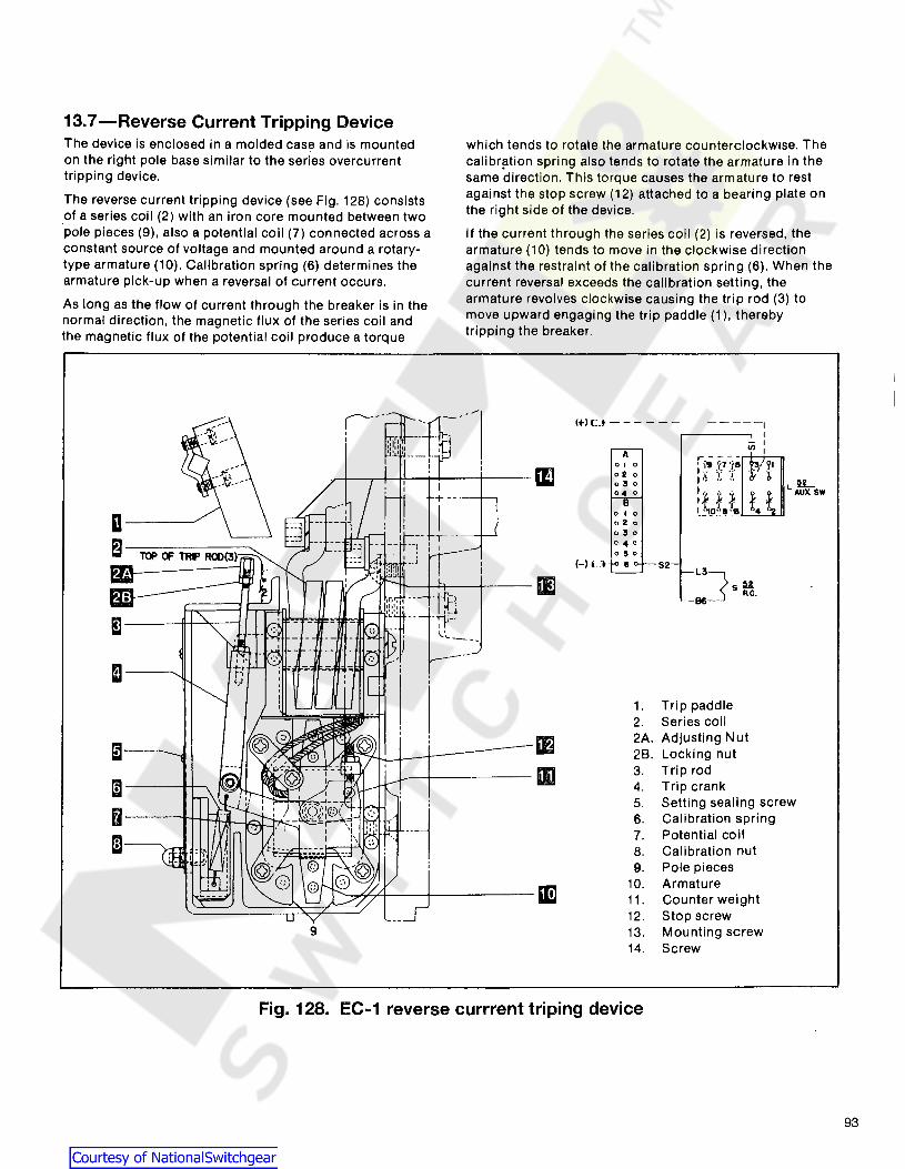
13.7-Reverse Current Tripping DeviceThe device is enclosed in a molded case and is mountedon the right pole base similar to the series overcurrenttripping device.
The reverse current tripping device (see Fig. 128) consistsof a series coil (2) with an iron core mounted between twopole pieces (9), also a potential coil (7) connected across aconstant source of voltage and mounted around a rotarytype armature (10). Calibration spring (6) determines thearmature pick-up when a reversal of current occurs.
As long as the flow of current through the breaker is in thenormal direction, the magnetic flux of the series coil andthe magnetic flux of the potential coil produce a torque
which tends to rotate the armature counterclockwise. Thecalibr!ition spring also tends to rotate the armature in thesame direction. This torque causes the armature to restagainst the stop screw (12) attached to a bearing plate onthe right side of the device.
If the current through the series coil (2) is reversed, thearmature (10) tends to move in the clockwise directionagainst the restraint of the calibration spring (6). When thecurrent reversal exceeds the calibration setting, thearmature revolves clockwise causing the trip rod (3) tomove upward engaging the trip paddle (1), therebytripping the breaker.
(+) c.t - - - - - - -----,I
-I
AIJI,
r - - - -01 0 ' ·Ct 'iT :'5 ;" jl
III 02 0 I {- :'l: .:.: It' "60;' 0 I" " ..
LA~SW04 0 :~ ~ ~ ttII
'_~'l9~l! !.
~52 L3]IE sH.
-86-
!1
m1. Trip paddle2. Series coil
IE 2A. Adjusting Nut~ 28. Locking nut
lID 3. Trip rod
~ 4. Trip crank5. Setting sealing screw
fa 6. Calibration spring
m 7. Potential coil8. Calibration nut9. Pole pieces
mJ10. Armature11. Counter weight12. Stop screw
9 13. Mounting screw14. Screw
Fig. 128. EC-1 reverse currrent triping device
93

SECTION 13-Type EC Overcurrent Trip Device
13.7.1-AdjustmentsThe only adjustment to be made on the reverse currentdevice is to make sure that the trip rod has a minimumovertravel of 1/32 in. beyond the point of tripping thebreaker. This adjustment should have to be made onlywhen an old device is being replaced by a new one.
The new device will be factory adjusted so that the top endof the trip rod (3) will extend 1/2 in. above the top of thedevice case, and no additional adjustments of the trip rodshould be required. To obtain the proper 1/32 in.overtravel, close the breaker and proceed as follows:
1. Loosen the locking nut. (2B).
2. Manually lift the trip rod and vary the position of theadjusting nut (2A), this establishing the position of theadjusting nut where the breaker is just tripped.
NOTE: Be sure to keep clear of moving breakerparts when tripping the breakers.
. 3. With this position of the adjusting nut established,advance the adjusting nut upward one and one-half turns.
4. Tighten the locking nut and the minimum 1/32-in.overtravel of the trip rod should be obtained.
13.7.2-Replacement
After removing the wiring for the potential coil the reversecurrent device can be removed and replaced by followingthe procedure outlined for replacing the series overcurrentdevice. See Section 11.9. For wiring, see Fig. 128.
13.8-Switchette FeatureThe switchette is operated by the long-time delay function.Its purpose is to provide a set of contacts that will closebefore an overload occurs. This device will not trip thebreaker on overload it will trip on instantaneous only.
94
The switchette feature is available only in type EC-1devices.
The switchette is used in one pole and EC-1 trips in theother poles. For the alarm to be effective in indicating theoverload before the other poles trip the breaker, the devicemust have less time delay than the other two poles; this isaccomplished by using a lower characteristic on the alarmdevice than the other poles or setting the alarm deviceslong time setting at 80%.
13.9-Trip Device ReplacementOvercurrent devices on the AKS50 breakers can bereplaced as follows:
a. Separate frames a~ described in Section 5.3
b. Referring to Fig. 126, remove bolts securing the seriescoil (1) to the lower stud.
c. Remove the clamping bracket (20).
d. Before installing the replacement device, check thetravel of trip arm as described in Section 11.5.4 and Fig.127.
e. Replace new device in reverse order.
f. Adjust the new device as described in Section 11.5.4
When replacing an EC-1 device with an EC-2 or EC-2Adevice, it may be necessary to replace the trip paddles onthe trip shaft with slightly longer ones. If paddlereplacement is required, new paddles are provided with thereplacement trip units.
Pickup settings on the cover of the EC-2, EC-2A device arecalibrated for the specific device. When replacing covers,replace on associated device.

Table 27Charging timesTable 28Shunt trip and undervoltage deviceTable 29Coil resistance
SECTION 14-Electrical CharacteristicsTable 23Charging and closing operating currentsTable 24Bell alarm contact-ratingTable 25Auxiliary switch contact sequenceTable 26Auxiliary switch contact ratings
TABLE 23-Charging and Closing Operating Currents
~MOTOR CD ANTI-PUMP CONTROL CLOSING
c Current (Amps) RELAY"W" RELAY "X" SOLENOID..u >- z:
u !! Rated·Amps .I!l Rated Amps .I!l Rated Amps cfti ... c ...
~ Cco. Cco. i=c CfI ... N CfI ... .. co. wfrl.- '" "'::I:
'" CfI ~~.~q; > '" Inrush Sealed > '" Inrush Sealed > '" Inrush SealedE= ... =c /!.."," - 0 - 0 - 0 en ....... ~ .. '" ,~ ,,:>~.. c'" c'" c'" ::l wz> .... >cc: iiii: Open Closed
._ u
dpen Closed·._ u
Open Closed .... en::Eii: :lEii:
48V DC 38·56 40 10 38 .063 .063 30 4.1 4.1 38 2.7 2.7 20A
125V DC 100·140 27 5 85 .024 .024 90 1.05 1.05 100 1.3 1.3 20A
250V DC 200-280 13 3 170 .015 .015 180 .53 .53 200 .68 .68 20A
120V 60 .090 .052 1.0 1.4 2.6 .35 20A
120V 50 104-127 25 5 95 .090 .052 95 1.0 .15 98 2.2 .29 20A
120V 25 .047 .032 6.85 1.27 1.1 .17 20A
208V 60 .050 .029 .45 .063 1.5 .19 20A
208V 50 180·220 15 3.5 175 .050 .029 175 .55 .083 177 1.2 .16 20A
208V 25 .032 .018 3.86 .76 .60 .08 20A
250V 60 .064 .036 .50 .07 1.3 .17 20A
250V 50 208-254 12 3 190 .064 .036 190 .50 .08 196 1.1 .15 20A
250V 25 .035 .023 3.42 .64 .54 .08 20A
CD Values are typical and are given only as application information, and not intended to be maximum or minimum values.
Table 24-Bell AlarmContact Rating
Bell Alarm Contact'Control Rating (amperes)Voltage
Inrush Contin-uous
Dc 125 2.5 2.5250 0.9 0.9
60 Hz. 120 30 10
Ac 240 15 5480 7 3
Table 25-Auxiliary SwitchContact Sequence
CB Auxiliary Switch Position
Main "a" "b"Contacts Contact Contact
Open'Closedor Open
Tr,ipped
Closed Closed Open
Table 26-Auxiliary SwitchContact Rating
Auxiliary Switch
ControlInterrupting Ratings
(Amperes)CDVoltage
Non·Inductive
Inductive
48 25 -Dc 125 11 6.3
250 2 1.8
115 75 50Ac 240 50 25
480 25 12CD Limited to 20A continuous rallng of
switch on all breakers and to 5A continuous rating of # 16 wire on drawoutbreakers.
Table 27Charging Times
Nominal TimeVoltage (sec.) CD
48VDC 2.0
125VDC 1.7250VDC
120VAC 1.5208VAC 1.7240VAC 1.3
CD Closing spring charging times aretypical values. The maximumpermitted is 5 seconds.
95

SECTION 14-Electrical Characteristics
TABLE 28-Shunt Trip and Undervoltage Device Operating Currents
e SHUNT TRIP UNDER VOLTAGEC
Current Current0 ,.,U 0» u
(Amps) (Amps)01 c- co 0» Nco _c- ~p: Inrush Sealed._ 0 Operating Inrush SealedE> ~ Operating0 --Z LL Voltage range Open Closed Voltage range Open Closed
24 DC 14 30 8.3 8.3 .38 .3848 DC 28 60 4.5 4.5 .19 .19
125 DC 70 140 2.0 2.0 .08 .08250 DC 140 280 1.0 1.0 .04 .04
70 60 59 132OJ N/A N/A- - 0>ro
120 60 95 127 12.3 10.8 - .66 .24<5120 50 95 127 7.6 6.7 > .75 .25OJ-
120 25 95 127 4.7 4.1 Ole .31 .10ro-_ c
208 60 175 220 3.2 2.6 - 0 .51 .17~()208 50 175 220 3.8 3.1 (ij(ij .30 .10
c c208 25 175 220 2.1 1.9 'E 'E .14 .05240 60 190 254 3.9 3.4
o 0.37 .12ZZ
..........240 50 190 254 4.7 4.1 o 0 .34 .11240 40 190 254 5.8 5.1 ~PR N/A N/AOJO
-CD240 25 190 254 2.1 1.9 L. I .16 .06
o~
380 50 315 410 2.9 2.6 ;,Ro .22 .08~C')
480 60 380 508 3.4 3.1 co- .23 .08_ ro
480 50 380 508 7.5 7.3 ro- .17 .06:J0.0 ._-
480 25 380 508 3.5 3.3 :Jo. .11 .05ti 0575 60 475 625 2.8 2.5
._ L.
.16 .060.0
575 50 475 625 5.1 4.7 .14 .06
[ 575 25 475 625 3.1 3.0 See Table 30 .10 .05
TABLE 29-Coil Resistance-DC Ohms @ 25°
96
Nominal Control Antl·Pump Control ShuntVoltage Frequency Hz Relay"W" Relay "X" Trip Undervoltage
24V DC N/A N/A 3 6448V DC 802 12 11 240125V DC 5000 119 64 1600250V DC 16400 476 260 6700120V 60 450 54 3.9 25.4120V 50 450 75 7.15 33120V 25 1450 75 25.4 146208V 60 1450 216 25.4 64208V 50 1450 300 25.4 146208V 25 3900 300 64 580240V 60 1450 300 25.4 100240V 50 1450 300 25.4 146240V 25 6000 300 64 580380V 50 N/A N/A 64 370480V 60 N/A N/A 64 370480V 50 N/A N/A 32 580480V 25 N/A N/A 100 1600575V 60 N/A N/A 100 580575V 50 N/A N/A 64 918575V 25 N/A N/A 146 3200
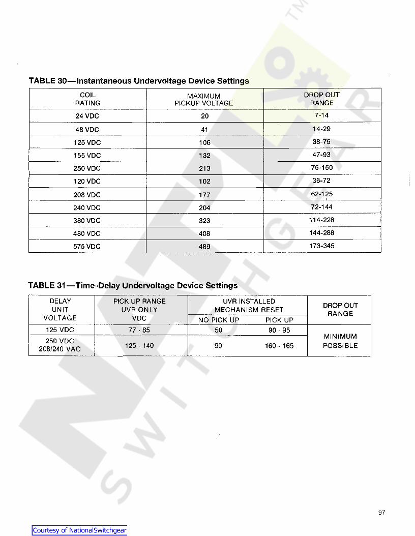
TABLE 30-lnstantaneous Undervoltage Device Settings
COIL MAXIMUM DROP OUTRATING PICKUP VOLTAGE RANGE
24VDC 20 7-14
48VDC 41 14-29
125 VDC 106 38-75
155 VDC 132 47-93
250VDC 213 75-150
120 VDC 102 36-72
208 VDC 177 62-125
240 VDC 204 72-144
380 VDC 323 114-228
480 VDC 408 144-288
575 VDC 489 173-345
TABLE 31-Time-Delay Undervoltage Device Settings
DELAY PICK UP RANGE UVRINSTALLEDDROP OUT
UNIT UVR ONLY MECHANISM RESET RANGEVOLTAGE VDC NO PICK UP PICK UP
125 VDC 77 - 85 50 90 - 95
250 VDCMINIMUM
208/240 VAC 125 - 140 90 160 - 165 POSSIBLE
97


These instructions do not purport to cover all details or variations in equipment nor to provide for every possihlecontingency to he met in connection with installation operation or maintenance. Should further information hedesired or should particular prohlems arise which are nOl covered sutnciently for the purchaser's purposes, thematter should be referred to the GE Company.
GEK-64460A
GE Electrical Distribution &Control
General Electric Company41 Woodford Ave., Plainville, CT 06062
© 1993 General Electric Company