lpca rmb gb - chillerele · general the lpca-rmb series air-cooled water chillers consists of 12...
TRANSCRIPT

PACKAGED AIR COOLED WATER CHILLERCOOLING ONLYOUTDOOR INSTALLATION
Cooling Capacity: 188,2 kW - 597,9 kWR407c - Tandem Scroll
LPCA 055-060-070-075-085-090-100-115 125-135-150-170RMB
FeaturesOptimized design for R407c refrigerant.Casing:Galvanized steel plate with polyesteric coating.
AssemblyFully bolted/welding free.
Compressor:∏ermetically sealed Tandem scroll type.
Air heat exchanger:Cross fin coilInternally grooved copper tubes and louvered aluminium fins.
Direct drive propeler fanLow rpm, quiet operation.
Water heat exchangerShell and tube type.
Safety and functional devices- High/low pressure switch.- Phase sequence - phase failure - reverse phase and voltage
monitoring device.- Evaporator low water temperature protection.- Electronic microprocessor control with digital display.- Differential water pressure switch.- High/low pressure manometers.
The Interklima LPCA - RMB large capacityseries are packaged air cooled water chillersfor cooling applications and outdoorinstallation. They are available in 12 modelswith nominal capacities ranging from 188,2to 597,9 kW.
This series is ideal in combination withInterklima fan coil or air handling units foroffice buildings, hotels, hospitals, shoppingcenters, restaurants, etc., or for supplyingchilled water for industrial applications.

NOMENCLATURE
1 RangeS-small M-mid L-large R-screw-series
2 Packaged Chiller Air-cooledPCA
3 Model numbers 055-060-070-075-080-085-090-095-100-105-110-115-120-125-135-140-150-160-170-190
4 Cool / Heat ModelR-cooling only H-heat pump
5 Compressor typeS-scroll M-tandem scroll R-reciprocatingT-twin screw
6 Refrigerant typeA-R22 B-R407c
7 Electrical Characteristic-1 Single phase -Ommited Three phase

Interklima Hydronic systemsLPCA 055-170RMB ñ R407c/Tandem Scroll 3
1. Technical Description
2. Specifications
3. Capacity Tables
4. Water Pressure Drop Curves
5. Operation Range
6. Sound Data
7. Outlook Drawings
8. Refrigerant Circuit Diagrams
9. Wiring Diagrams
10. Installation
11. Guide Specifications
Contents

GeneralThe LPCA-RMB series air-cooled water chillers consists of 12models covering capacities from 188.2 up to 597.9 Kw.It is the end result of a thorough study, and accurate design byexperienced Interklima research and development teams, todevelop a large size chiller series with compact shape, highperformance, and reliability of the highest quality standards.This series meets the highest levels of aesthetic and technicalrequirements using the latest technological innovations includingenvironmentally friendly R407c refrigerant that is Chlorine-freeand has zero ozone depletion potential. LPCA-RMB units aretherefore ideal for installation in urban environments due to theirelegant design, selected materials and low operating sound levels.
CasingAll units use metal parts fabricated from heavy gauge galvanizedsteel sheets, formed to ensure maximum rigidity that guaranteesand preserves the units operation during the years. Afterfabrication these are degreased, phosphatised, andelectrostatically powder coated with an epoxy-polyester RAL 9002coating of a thickness 60-70 Ì. This fully automatic processensures superior corrosion resistance against the mostaggressive ambient conditions. The treatment can successfullywithstand a salt spray test of 500 hours, according to ASTM B-117. All components are assembled together using bolts thusavoiding the need for welding which may harm the galvanizationof the steel, and ensures that the whole assembly can fullywithstand adverse weather conditions.The compact footprint of the unit arises from detailed study anddesign by our engineering teams and results in a machine, whichfits easily in restricted areas and is simple and easy to install andmaintain, and has been designed with special fittings for easytransport and lifting.Removable side panels are used to permit access only toauthorized personnel to internal components of the unit forinspection and maintenance. Electrical and electronic equipmentand components for proper unit operation are located in a weatherproof (IP 55) electrical panel with access via only a special key.
CompressorAll units’ use low-noise, maintenance free, Hermetic Tandem Scrollcompressors with low vibration levels, specially optimized for usewith R407c refrigerant, selected from world class suppliers.They are equipped with a crankcase electrical heater for the oil, andare internally protected against potential overloading or electricalspikes. The compressors are mounted on special antivibrationrubber mounts to eliminate vibration from the unit’s operation.
Air heat exchanger All unit air heat exchangers are manufactured from high qualitycopper inner grooved seamless tubes according to ASTM B-280,having an outside diameter of 9,52 mm (3/8"). The fins aremanufactured from aluminium and form the secondary extendedheat transfer surface. The fins are continuous across the heatexchanger and are fabricated in high precision dedicated presslines. The fin surface is waffle formed, so as to increase the finrigidity, and has special louvers that help increase heat transfer.The combination of internally grooved Copper-tubing and louveredfins has resulted in a heat transfer performance 30% superior tothat of a conventional coil for this particular application. Theassembly of the finned pack is achieved by mechanical expansionof the tubes in such a way as to form a perfect mechanical bondwith the fins. For this purpose, the fin holes have a peripheralextrusion (collar) of adjustable height. This extrusion serves todefine the distance between fins (and consequently the total heattransfer surface) and to ensure perfect contact of the fins to thetubes. Alternative fin materials are available upon request such asepoxy – coated aluminium or copper for applications in especiallyaggressive environments.
Water heat exchangerAll units are equipped with a Shell and Tube water direct expansiontype evaporator that has multiple cooling circuits, one for eachindependent refrigerant circuit. The casing is of steel and theinternal tubes are of copper. There is an air vent valve, drain valve,probes for water temperature sensors, differential pressure switchand the whole heat exchanger is wrapped in a heavy insulationmaterial appropriate for external installation.
Air heat exchanger fansAll unit fans are of the axial type, three phase, 6 poles, internallyprotected against potential overheating silent and suitable foroutdoor installation. Due to the sophisticated aerodynamic designof the blades and inlet cones, as well as the perfect static anddynamic balancing, their operation is completely vibration-free.The fan-motor assembly has a protective grid against accidentalcontact with moving parts, which is designed according to ISOregulations. Fan motors are aerodynamically shaped so as not tointerfere with the airflow, and have permanently lubricatedbearings that do not require servicing. Continuous linear fan speedregulation control is achieved according to coil temperaturesincluding fan silent mode operation. This is an optional feature forInterklima LPCA units that saves energy and reduces sound levelsdramatically, optimizing capacity.
Interklima Hydronic systemsLPCA 055-170RMB ñ R407c/Tandem Scroll4
Technical Description1.

Microprocessor controllerAll units are equipped with an electronic programmable controlsystem. This allows complete management of all the functions ofthe unit and ensures protection of all vital parts. It has adiagnostics function, permitting easy and straightforwardunderstanding of all the possible failures and malfunctions of theunit. All functions and indicators appear on the LCD screen. Over150 programmable parameters offer complete unit management.
Critical parameters that require control are:ñ Start-up shut down time of compressor.ñ Time delay.ñ Protection against multiple start-up.ñ Water pump time delay in reference to compressor
operation.ñ Inlet/Outlet water temperature.ñ Air heat exchanger temperature.
Controlled operational parametersñ Water temperature adjustment in the inlet side during
summer operation*.ñ Water outlet temperature adjustment in summer operation**.ñ Compressor capacity control.
Controlled fault parametersñ Low suction pressure per refrigerant circuit.ñ High discharge pressure per refrigerant circuit.ñ Compressor overload.ñ Fan motor overload.ñ Water pump overload.ñ Flow switch fault.ñ Water sensor error due to bad contact or sensor failure.ñ Error reading in water outlet low temperature.ñ Compressor operating hour reading.
In addition the control also includeñ Self diagnostic error of all electronic control sensors.ñ Remote on/ off switch.ñ Remote alarm indication capability.ñ Remote cool/heat selector switch.ñ History of operation points and fault codes**.ñ Password access code.
Refrigerant circuitThe units have multiple refrigerant circuits depending on the sizeone per tandem compressor.
Each circuit consists of the following:ñ Thermal expansion valve.ñ Filter drier with a replaceable core.ñ Shut off valves.ñ 2-way solenoid valve.ñ High and low pressure gauges for each refrigerant circuit,
easily viewed.ñ Service valves.ñ Unit protection is provided by a high pressure switch with
manual reset, low pressure protection is a low-pressureswitch with auto reset.
ñ Flexible refrigerant pipe on the compressor discharge andsuction lines to avoid vibration and noise.
Optional accessoriesMicroprocessor controller optionsñ BMS module interface kit for Bacnet, Lon Works and Trend
connection**.ñ BMS interface kit for Modbus connection.ñ Connection via internet using a device converting the Carel
protocol to 10Mb/s TCP/IP ethernet protocol**.ñ Possibility to send and receive messages using a GSM
modem**.ñ Communication card through RS232 / RS485 serial ports.ñ Extended memory card for up to five thousands
messages**.ñ Extended memory card 1&2 MB**.ñ Parallel chiller operation with standard controller for units
with a maximum of eight compressors*.ñ Microprocessor parameter reprogramming card.ñ Compressor running current**.ñ Self diagnostic and adaptive control**.
Other unit accessories/optionñ R407c or R22 refrigerant.ñ Condenser fins made of copper or prepainted aluminum, and
Blygold treatment for corrosion protection.ñ Glycol for chilled water temperature down to –5oC.ñ Continuous linear fan speed regulation.ñ High pressure relief valve on compressor discharge.ñ A-meter, V-meter.ñ Compressor noise reduction jacket.ñ Electrical board ventilation fan.ñ Water heat exchanger antifreezing electrical heater.ñ Other custom built options upon request.
* For models 055-085** For models 090 – 170
Interklima Hydronic systemsLPCA 055-170RMB ñ R407c/Tandem Scroll 5

Interklima Hydronic systemsLPCA 055-170RMB ñ R407c/Tandem Scroll6
Specifications2.
LPCA-055188,2
53.0
641.591
2(x2)
4
57.1
98.8
146.0
1
50.0
16
29
DN 100
32370
31.7
1129
4
850
81.700
8.0
18
19.2
65.1
116.8
165
0.38
120
3x200
2
69
2200
2600
2200
2070
LPCA-060214,6
61.0
731.591
2(x2)
4
65.0
110.7
164.0
1
50.0
16
29
DN 100
36911
40.9
1288
4
850
81.700
8.0
18
19.2
73.0
128.7
183
0.48
150
3x200
2
69
2200
2600
2200
2200
LPCA-070240,9
68.0
821.250
2(x2)
4
72.8
125.4
186.0
1
63.0
16
29
DN 100
41435
29
1445
4
850
77.000
8.0
18
19.2
80.8
143.4
205
0.54
150
3x225
2
69
2200
2600
2200
2300
LPCA-075267,3
76.0
911.250
2(x2)
4
80.6
140.2
208.0
1
63.0
16
29
DN 100
45976
37.2
1604
4
850
77.000
8.0
18
19.2
88.6
158.2
227
0.6
185
3x250
2
69
2200
2600
2200
2350
LPCA-085299,0
85.0
1.019.318
2(x2)
4
88.4
153.6
229.0
1
58.0
16
29
DN 100
51428
44.8
1794
4
850
75.000
8.0
18.0
19.2
96.4
171.6
248
0.6
240
3x300
2
69
2200
2600
2200
2530
LPCA-090321,9
91.0
1.097.386
3(x2)
6
97.5
166.0
246.0
1
88.0
16
29
DN 125
55367
34.3
1931
6
850
115.400
12.0
27.0
28.8
109.5
193.0
275
0.72
300
3x400
3
72
2200
3900
2200
3340
LPCA-100361,4
103.0
1.232.045
3(x2)
6
109.2
188.1
279.0
1
88.0
16
29
DN 125
62161
42.3
2168
6
850
112.500
12.0
27.0
28.8
121.2
215.1
308
0.81
300
3x400
3
72
2200
3900
2200
3410
Type
Nominal cooling capacity
Construction
Compressor
Quantity
Capacity steps
Absorbed power
Nominal operating current
Maximum operating current
Condenser
Evaporator
Quantity
Water content
Max. Operating pressure
Connections
Nominal water flow
Water pressure drop
Minimum system water content
Fan
Quantity
Speed
Total air flow
Absorbed power
Nominal operating current
Maximum operating current
Electrical characteristics
Total absorbed power
Nominal operating current
Maximum operating current
Compressor carter resistance power
Power cables cross section per phase
Fuses
Voltage operating limits
Refrigerant circuit
Number of circuits
Expansion device
Refrigerant type
Noise level @ 5m
Dimensions
Shipping weight
kW
RT
Btu/h
Material/Color
kW
A
A
l
Water side bar
Refrigerant side bar
l/h
kpa
l
rpm
m3/h
kW
A
A
kW
A
A
kW
mm2
A
V
dB(A)
Width mm
Length mm
Heigth mm
kg
Galvanized steel / Light grey-beige (RAL 9002)
Shell and Tube
400V/3Ph/50Hz
360-440V
thermal expansion valveR407c
Tandem Scroll
High capacity cross finned coil with internally groved and louvered fins
LPCA 055-170RMB

Interklima Hydronic systemsLPCA 055-170RMB ñ R407c/Tandem Scroll 7
NOTESNominal conditions areas follows:
-entering/leaving chilledwater temperature12/7oC; ambient35oCDB (cooling).
-electrical installationspecifications are purelyindicative and non-binding, all connectionsto the system and theelectrical installation mustbe in full accordance withall applicable national andlocal codes.
Galvanized steel / Light grey-beige (RAL 9002)
High capacity cross finned coil with internally groved and louvered fins
Shell and Tube
400V/3Ph/50Hz
360-440V
thermal expansion valve
R407c
Tandem Scroll
Type
Nominal cooling capacity
Construction
Compressor
Quantity
Capacity steps
Absorbed power
Nominal operating current
Maximum operating current
Condenser
Evaporator
Quantity
Water content
Max. Operating pressure
Connections
Nominal water flow
Water pressure drop
Minimum system water content
Fan
Quantity
Speed
Total air flow
Absorbed power
Nominal operating current
Maximum operating current
Electrical characteristics
Total absorbed power
Nominal operating current
Maximum operating current
Compressor carter resistance power
Power cables cross section per phase
Fuses
Voltage operating limits
Refrigerant circuit
Number of circuits
Expansion device
Refrigerant type
Noise level @ 5m
Dimensions
Shipping weight
kW
RT
Btu/h
Material/Color
kW
A
A
l
Water side bar
Refrigerant side bar
l/h
kpa
l
rpm
m3/h
kW
A
A
kW
A
A
kW
mm2
A
V
dB(A)
Width mm
Length mm
Heigth mm
kg
LPCA-115
400,9
114.0
1.366.705
3(x2)
6
120.9
210.2
312.0
1
80.0
16
29
DN 125
68955
38.3
2405
6
850
112.500
12.0
27.0
28.8
132.9
237.2
341
0.9
2x120
3x400
3
72
2200
3900
2200
3500
LPCA-125
448,4
127.0
1.528.636
3(x2)
6
132.6
230.4
343.5
1
134.0
16
29
DN 150
77.125
32.4
2690
6
850
112.500
12.0
27.0
28.8
144.6
257.4
372
0.9
2x150
3x400
3
72
2.200
3.900
2.200
3800
LPCA-135
481,9
137.0
1.642.841
4(x2)
8
145.6
250.9
372.0
1
134.0
16
29
DN 150
82.887
37.3
2891
8
850
154.000
16.0
36.0
38.4
161.6
286.9
410
1.08
2x150
3x500
4
74
2.200
5.200
2.200
4560
LPCA-150
534,5
152.0
1.822.159
4(x2)
8
161.3
280.3
416.0
1
135.0
16
29
DN 150
91.934
45.6
3207
8
850
150.000
16.0
36.0
38.4
177.3
316.3
454
1.2
2x185
3x600
4
74
2.200
5.200
2.200
4650
LPCA-170
597,9
170.0
2.038.295
4(x2)
8
176.8
307.0
458.0
1
114.0
16
29
DN 150
102.839
51.2
3587
8
850
150.000
16.0
36.0
38.4
192.8
343.2
496
1.2
2x240
3x600
4
74
2.200
5.200
2.200
4990

Interklima Hydronic systemsLPCA 055-170RMB ñ R407c/Tandem Scroll8
Capacity tables3.
LPCA-055
LPCA-060
LPCA-070
LPCA-075
LPCA-085
LPCA-090
LPCA-100
LPCA-115
LPCA-125
LPCA-135
LPCA-150
LPCA-170
Water outlet ÆC
Coolingcapacity
kW
Absorbedpower
kW
CurrentA
Absorbedpower
kw
CurrentA
Coolingcapacity
kW
Absorbedpower
kW
CurrentA
Coolingcapacity
kW
Absorbedpower
kW
CurrentA
Coolingcapacity
kW
Absorbedpower
kW
25 30 35 40 45
CurrentA
Coolingcapacity
kW
5
7
10
5
7
10
5
7
10
5
7
10
5
7
10
5
7
10
5
7
10
5
7
10
5
7
10
5
7
10
5
7
10
5
7
10
197.6
213.1
238.2
225.6
243.5
272.1
255.1
275.6
308.7
284.5
307.8
345.3
315.9
341.8
383.6
338.4
365.2
408.2
382.6
413.5
463.1
426.8
461.7
518.0
473.9
512.7
575.4
510.2
551.3
617.5
569.1
615.6
690.7
631.9
683.5
767.2
45.2
45.4
45.7
51.7
51.9
52.0
58.2
58.5
59.0
64.7
65.2
65.9
70.9
71.4
72.2
77.6
77.8
78.0
87.3
87.8
88.4
97.1
97.8
98.8
106.4
107.1
108.3
116.5
117.1
117.9
129.5
130.3
131.8
141.8
142.8
144.3
83.9
84.0
84.1
93.4
93.6
94.1
107.0
107.3
107.8
120.5
120.9
121.6
130.8
131.3
132.1
140.1
140.5
141.1
160.5
160.9
161.8
180.8
181.4
182.4
196.1
196.9
198.2
214.0
214.6
215.7
241.1
241.9
243.2
261.5
262.5
264.3
186.0
200.9
224.9
212.3
229.4
256.9
238.9
258.5
290.1
265.6
287.7
323.4
296.2
320.7
360.5
318.4
344.0
385.3
358.4
387.8
435.2
398.4
431.6
485.1
444.3
481.1
540.7
477.9
517.1
580.3
531.2
575.5
646.8
592.4
641.5
721.0
50.7
50.8
51.0
57.8
58.1
58.4
64.9
65.2
65.6
71.9
72.3
72.9
78.9
79.2
79.9
86.7
87.1
87.6
97.3
97.8
98.4
107.9
108.4
109.3
118.3
118.9
119.8
129.7
130.3
131.3
143.8
144.6
145.8
157.8
158.5
159.7
90.7
90.8
90.9
101.2
101.5
101.9
115.3
115.5
116.0
129.3
129.6
130.1
141.0
141.4
142.1
151.9
152.2
152.8
172.9
173.3
174.0
194.0
194.4
195.2
211.5
212.1
213.1
230.5
231.1
232.0
258.6
259.2
260.3
282.0
282.8
284.2
174.0
188.2
211.1
198.3
214.6
240.9
222.3
240.9
271.0
246.3
267.3
301.1
275.6
299.0
336.7
297.4
321.9
361.4
333.4
361.4
406.5
369.5
400.9
451.6
413.4
448.4
505.1
444.6
481.9
542.0
492.6
534.5
602.2
551.2
597.9
673.4
57.0
57.1
57.2
64.7
65.0
65.4
72.5
72.8
73.3
80.4
80.6
81.1
88.2
88.4
88.9
97.1
97.5
98.2
108.8
109.2
109.9
120.6
120.9
121.6
132.2
132.6
133.3
145.1
145.6
146.5
160.8
161.3
162.2
176.3
176.8
177.8
98.6
98.8
98.9
110.5
110.7
111.1
125.2
125.4
125.8
140.0
140.2
140.5
153.3
153.6
154.1
165.7
166.0
166.6
187.8
188.1
188.7
209.9
210.2
210.8
230.0
230.4
231.2
250.5
250.9
251.6
279.9
280.3
281.1
306.6
307.2
308.2
161.6
175.1
196.9
183.6
199.2
224.3
205.2
222.8
251.3
226.7
246.4
278.4
254.0
276.2
312.0
275.4
298.8
336.4
307.7
334.2
377.0
340.0
369.6
417.6
380.9
414.2
468.0
410.3
445.6
502.6
453.4
492.9
556.7
507.9
552.3
624.0
64.2
64.3
64.4
72.6
72.9
73.4
81.5
81.7
82.1
90.3
90.4
90.7
98.9
99.1
99.4
109.0
109.4
110.1
122.2
122.5
123.1
135.4
135.6
136.0
148.4
148.6
149.1
162.9
163.3
164.1
180.5
180.8
181.4
197.8
198.2
198.8
108.0
108.1
108.3
121.4
121.6
121.9
137.1
137.3
137.6
152.8
152.9
153.2
168.0
168.2
168.6
182.1
182.4
182.9
205.7
205.9
206.3
229.3
229.4
229.8
252.0
252.3
252.8
274.3
274.6
275.1
305.7
305.9
306.4
336.0
336.4
337.1
148.7
161.5
182.1
168.4
183.1
207.0
187.6
204.2
231.1
206.7
225.2
255.3
231.0
252.1
286.1
252.6
274.7
310.4
281.3
306.3
346.7
310.1
337.9
382.9
346.5
378.2
429.1
375.1
408.4
462.2
413.4
450.5
510.5
462.0
504.2
572.2
72.4
72.5
72.6
81.8
82.0
82.5
91.8
91.9
92.2
101.7
101.7
101.8
111.3
111.4
111.6
122.7
123.1
123.7
137.6
137.8
138.2
152.6
152.6
152.8
166.9
167.1
167.3
183.5
183.8
184.3
203.5
203.5
203.7
222.5
222.7
223.1
119.0
119.1
119.3
134.3
134.4
134.7
151.3
151.4
151.5
168.3
168.3
168.4
185.3
185.4
185.7
201.5
201.7
202.1
226.9
227.0
227.3
252.4
252.4
252.5
277.9
278.2
278.5
302.6
302.7
303.1
336.5
336.6
336.7
370.6
370.9
371.4
Type
Ambient temperature oC
Cooling capacity table for LPCA 055-170RMB
NOTESBold values show nominal cooling capacities.Absorbed power and current refers to the compressor.Above figures are valid for water ¢t = 5ÔC.

Interklima Hydronic systemsLPCA 055-170RMB ñ R407c/Tandem Scroll 9
Water pressure drop curves4.
1501008070605040302015
100
90
80
70
60
50
40
30
20
15
1000 x I/h
kpa
PD
WF
1 2 3 4 5 6 7
LPCA 055-170RMB
% ETHYLENE GLYCOL BY VOLUME
Freezing point
Output duty
Input pow er
Equivalent Flow rate
Equivalent Pressure drop
ETHYLENE GLYCOL CORRECTION FACTORSUNIT 10oC
kW
kW
L/H
kPa
-4
0,99
0,99
1,02
1,06
20
-9
0,98
0,98
1,04
1,12
30
-15
0,97
0,98
1,08
1,18
40
-23
0,96
0,97
1,13
1,25
NOTESPD: pressure drop through the unitWF: water flow rate water heat exchanger1. LPCA 055-060RMB2. LPCA 070RMB3. LPCA 075-085RMB4. LPCA 090-100RMB5. LPCA 115RMB6. LPCA 125-135-150RMB7. LPCA 170RMB

LPCA-055
LPCA-060
LPCA-070
LPCA-075
LPCA-085
LPCA-090
LPCA-100
LPCA-115
LPCA-125
LPCA-135
LPCA-150
LPCA-170
Power Pressure @1 mPressure @10 mPower Pressure @1 mPressure @10 mPower Pressure @1 mPressure @10 mPower Pressure @1 mPressure @10 mPower Pressure @1 mPressure @10 mPower Pressure @1 mPressure @10 mPower Pressure @1 mPressure @10 mPower Pressure @1 mPressure @10 mPower Pressure @1 mPressure @10 mPower Pressure @1 mPressure @10 mPower Pressure @1 mPressure @10 mPower Pressure @1 mPressure @10 m
Type Octave band center frequency (Hz)dB(∞)
918363918363918363918363918363948666948666948666948666968868968868968868
63837555837555837555837555837555857757857757857757857757867858867858867858
125817353817353817353817353817353837555837555837555837555847656847656847656
250807252807252807252807252807252827454827454827454827454837555837555837555
500857757857757857757857757857757877959877959877959877959888060888060888060
1000888060888060888060888060888060908262908262908262908262918262918262918262
2000918363918363918363918363918363938565938565938565938565948666948666948666
4000847556847556847556847556847556857757857757857757857757867858867858867858
8000726444726444726444726444726444746646746646746646746646756747756747756747
45
-50
6 15
Outdoor Temperature ( CDB) COOLINGO
Leaving water temperature(oC)
4
18
47 NOTESProtect the water circuit against freezing
Required continous linear fan speed regulation control.
- The accompanying operating limits are for general guidance only. It may bepossible for certain units to operate outside the confines of the graph. Pleasecontact Interklima if further clarification is required.
- For operation with leaving water temperature below 6 oC it is required to confirmwith Interklima at the time of order and the addition of glycol into the system.
Interklima Hydronic systemsLPCA 055-170RMB ñ R407c/Tandem Scroll10
Operation range5.
Sound data6.
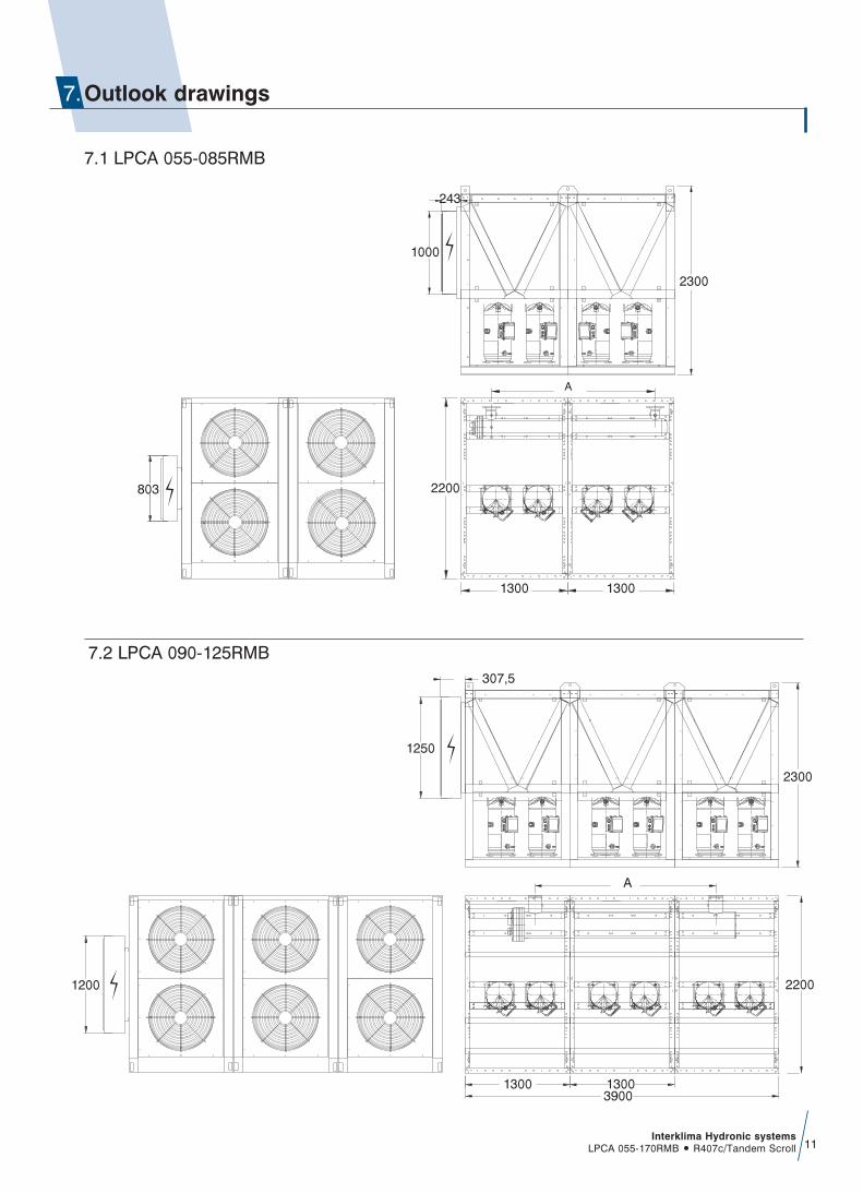
1250
2200
1300 13003900
2300
1200
A
307,5
Interklima Hydronic systemsLPCA 055-170RMB ñ R407c/Tandem Scroll 11
243
1000
2300
A
2200803
1300 1300
7.2 LPCA 090-125RMB
7.1 LPCA 055-085RMB
Outlook drawings7.
Interklima Hydronic systemsLPCA 055-170RMB ñ R407c/Tandem Scroll12
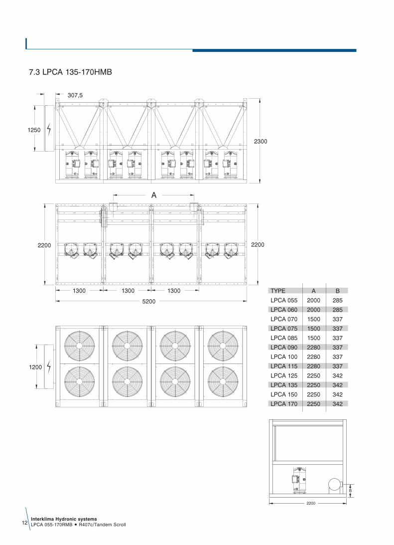
2300
2200
1200
1250
2200
1300 1300
5200
1300
A
307,5
7.3 LPCA 135-170HMB
TYPE
LPCA 055
LPCA 060
LPCA 070
LPCA 075
LPCA 085
LPCA 090
LPCA 100
LPCA 115
LPCA 125
LPCA 135
LPCA 150
LPCA 170
B
285
285
337
337
337
337
337
337
342
342
342
342
A
2000
2000
1500
1500
1500
2280
2280
2280
2250
2250
2250
2250
2200
B
Interklima Hydronic systemsLPCA 055-170RMB ñ R407c/Tandem Scroll 13
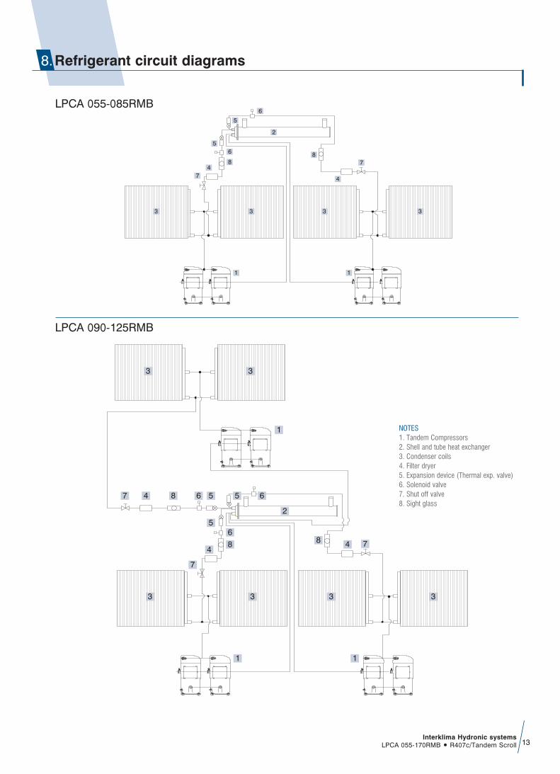
Refrigerant circuit diagrams8.
3 3
74
8
65
5
6
2
3
4
8
11
7
3
3
1
7 4 8
8
6 5
5
448
1 1
6
7
7
6
2
5
3
3 3 3 3
LPCA 055-085RMB
LPCA 090-125RMB
NOTES1. Tandem Compressors2. Shell and tube heat exchanger3. Condenser coils4. Filter dryer5. Expansion device (Thermal exp. valve)6. Solenoid valve7. Shut off valve8. Sight glass

3
7 4
85
44
7
1
11
1
7
7
4
55
566 8
8 8
62
6
3
3 3 3 3
3 3
Interklima Hydronic systemsLPCA 055-170RMB ñ R407c/Tandem Scroll14
NOTES1. Tandem Compressors2. Shell and tube heat exchanger3. Condenser coils4. Filter dryer5. Expansion device (Thermal exp. valve)6. Solenoid valve7. Shut off valve8. Sight glass
LPCA 135-170RMB

CF2
CF1
A
C
H
P
T
ENER
GY 4
00
N
L3L2L1
ALAL
NN
LP1
L
P1P2
L
S
4SV
1
SV1 SV2
SV2
F1 F2 VC
CC1
FLOW
SW
ITCH
LP2
9 105 6 873 421
S4S1S2S3
S
12
SS
3
ON
OFF
ST5ID6ID7
ST6ID8ID11
ID9NC
ID10GND
TK2GND
12DCALL
12AC12AC
_
FROM POWER CIRCUIT
CONTROL CIRCUIT
+
S
12AC12AC
ALL12DC
GNDTK1
GNDID5
ST4ID4
ST3ID3
ST2ID2 ID1
ST1
220V F
SW
CC1
CC3
CC2
HP2
H
P2
T
C2C1
T
Ltc1 Ltc2
REM
OTE
ON-O
FF
EXPANSION
CC3
CC4
T
C3
T
C4F2
TC1
TC2
TC3
TC4
T
RELA
Y 9
RELA
Y 10
TF2
HP1
H
P1
F1
T
TF1
12V
9.1 LPCA 055-085RMB
9.Wiring diagrams
Interklima Hydronic systemsLPCA 055-170RMB ñ R407c/Tandem Scroll 15
NCF1 CF2
CM3
V3U3
CC3
W4U4 V4W3
CM4
CC4
CC2
CH1 CH2
CC1
RVC
S T
PE
L1
L3
N
L2
FC3 FC4
SM1 POWER CIRCUIT
CH1 CH2
N N
CH3
N
CH3
CC3
CH4
N
CH4
CC4
CM1
U1 V1 W1
CM2
W2U2 V2
FC1
CC1 CC2
FC2
FCH
SF1,2
FF1
SF3,4
FF2
UF1 VF1 WF1 UF2 VF2 WF2
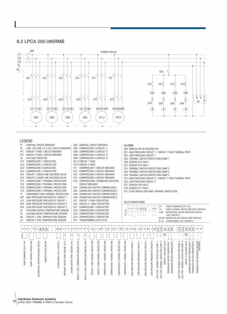
C-P PUMP COMMAND (220 V AC)T-H PUMP THERMAL PROTECTION (DRY CONTACT)F-SW DIFFERENTIAL WATER PRESSURE SWITCH (DRY CONTACT)ON-OFF REMOTE ON-OFF SWITCH (DRY CONTACT)AL-AL ALARM SIGNAL (N.O. CONTACT)
TC P H
220
V AC
SW ON OFFF AL AL
FIELD CONNECTIONS
A
220
V AC
HPC T
CH2
P2 P2L
LTC1C1F2 T HT C2 LP1 P1 HF
OFF
ONSW
2SALAL 1 S SS 3 T4 F1 T
SV1
SV2
LTC3
CH4 NC3T T C4
LTC2
LTC4
CH1
CH3
PUM
P CO
MM
AND
(220
V A
C)
PUM
P TH
ERM
AL P
ROTE
CTIO
N
CIRC
UIT
1 SO
LENO
ID V
ALVE
LOW
PRE
SSUR
E PR
ESSO
STAT
CIR
CUIT
2
HIG
H P
RESS
URE
PRES
SOST
AT C
IRCU
IT 2
LOW
PRE
SSUR
E PR
ESSO
STAT
CIR
CUIT
1
COM
PRES
SOR
2 TH
ERM
AL P
ROTE
CTIO
N
CIRC
UIT
2 CO
IL T
EMPE
RATU
RE S
ENSO
R (S
T6)
220
V FO
R T
HER
MAL
PRO
TECT
ION
COM
P. 1
ENTE
RING
WAT
ER T
EMP.
SENS
OR
(ST1
)
CIRC
UIT
1 FA
NS T
HER
MAL
PRO
TECT
ION
COM
PRES
SOR
1 TH
ERM
AL P
ROTE
CTIO
N
HIG
H P
RESS
URE
PRES
SOST
AT C
IRCU
IT 1
CRAN
KCAS
E H
EATE
R CO
MPR
ESSO
R 2
LEAV
ING
WAT
ER T
EMP.
SEN
SOR
(ST2
)
CIRC
UIT
1 CO
IL T
EMPE
RATU
RE S
ENSO
R (S
T3)
CIR
CUIT
2 F
ANS
THER
MAL
PRO
TECT
ION
DIFF
EREN
TIAL
WAT
ER P
RESS
URE
SWIT
CH
REM
OTE
SW
ITCH
ON-
OFF
ALAR
M S
IGNA
L (N
.O. C
ONT
ACT)
220
V FO
R T
HER
MAL
PRO
TECT
ION
COM
P. 3
CRAN
KCAS
E H
EATE
R CO
MPR
ESSO
R 4
COM
MAN
D FO
R AN
TIFR
EEZE
HEA
TERS
(OPT
IONA
L)
CIRC
UIT
2 SO
LENO
ID V
ALVE
COM
PRES
SOR
4 TH
ERM
AL P
ROTE
CTIO
N
COM
PRES
SOR
3 TH
ERM
AL P
ROTE
CTIO
N
220
V FO
R T
HER
MAL
PRO
TECT
ION
COM
P. 2
220
V FO
R T
HER
MAL
PRO
TECT
ION
COM
P. 4
CRAN
KCAS
E H
EATE
R CO
MPR
ESSO
R 1
CRAN
KCAS
E H
EATE
R CO
MPR
ESSO
R 3
F1 CONTROL CIRCUIT BREAKERF2 LOW VOLTAGE (12 V AC) CIRCUIT BREAKERFF1 CIRCUIT 1 FANS CIRCUIT BREAKERFF2 CIRCUIT 2 FANS CIRCUIT BREAKERVC VOLTAGE SURVEYOR CC1 COMPRESSOR 1 CONTACTORCC2 COMPRESSOR 2 CONTACTORCC3 COMPRESSOR 3 CONTACTORCC4 COMPRESSOR 4 CONTACTORSV1 CIRCUIT 1 LIQUID LINE SOLENOID VALVESV2 CIRCUIT 2 LIQUID LINE SOLENOID VALVE TC1 COMPRESSOR 1 THERMAL PROTECTIONTC2 COMPRESSOR 2 THERMAL PROTECTIONTC3 COMPRESSOR 3 THERMAL PROTECTIONTC4 COMPRESSOR 4 THERMAL PROTECTIONTF CONDENSER FANS THERMAL PROTECTIONHP1 HIGH PRESSURE PRESSOSTAT CIRCUIT 1LP1 LOW PRESSURE PRESSOSTAT CIRCUIT 1HP2 HIGH PRESSURE PRESSOSTAT CIRCUIT 2LP2 LOW PRESSURE PRESSOSTAT CIRCUIT 2S1 ENTERING WATER TEMPERATURE SENSORS2 LEAVING WATER TEMPERATURE SENSORS3 CIRCUIT 1 COIL TEMPERATURE SENSORS4 CIRCUIT 2 COIL TEMPERATURE SENSOR
ALARMLEGEND
E00: REMOTE OFF IN POSITION OFFE01: HIGH PRESSURE CIRCUIT 1 / CIRCUIT 1 FANS THERMAL PROT.E02: LOW PRESSURE CIRCUIT 1 E03: THERMAL SWITCH PROTECTION COMP.1E06: SENSOR ST2 FAULTE07: SENSOR ST3 FAULTE13: THERMAL SWITCH PROTECTION COMP.2E23: THERMAL SWITCH PROTECTION COMP.3E33: THERMAL SWITCH PROTECTION COMP.4E21: HIGH PRESSURE CIRCUIT 2 / CIRCUIT 1 FANS THERMAL PROT.E22: LOW PRESSURE CIRCUIT 2E27: SENSOR ST6 FAULTE40: SENSOR ST1 FAULTE41: FLOW SWITCH OR PUMP THERMAL PROTECTION
SM1 GENERAL CIRCUIT BREAKERCM1 COMPRESSOR 1(CIRCUIT 1)CM2 COMPRESSOR 2 (CIRCUIT 1)CM3 COMPRESSOR 3 (CIRCUIT 2)CM3 COMPRESSOR 4 (CIRCUIT 2)SF1,2 CIRCUIT 1 FANSSF3,4 CIRCUIT 2 FANSFC1 COMPRESSOR 1 CIRCUIT BREAKERFC2 COMPRESSOR 2 CIRCUIT BREAKERFC3 COMPRESSOR 3 CIRCUIT BREAKERFC4 COMPRESSOR 4 CIRCUIT BREAKERFCH COMPRESSORS CRANKCASE HEATERS CIRCUIT BREAKERCH1 CRANKCASE HEATER COMPRESSOR 1CH2 CRANKCASE HEATER COMPRESSOR 2CH3 CRANKCASE HEATER COMPRESSOR 3CH4 CRANKCASE HEATER COMPRESSOR 4CF1 CIRCUIT 1 FANS CONTACTOR CF2 CIRCUIT 2 FANS CONTACTORCC1 COMPRESSOR 1 CONTACTOR CC2 COMPRESSOR 2 CONTACTOR CC3 COMPRESSOR 3 CONTACTOR CC4 COMPRESSOR 4 CONTACTORTR1 TRANSFORMER 220/12V AC
SV1 SV2
Interklima Hydronic systemsLPCA 055-170RMB ñ R407c/Tandem Scroll16
9.2 LPCA 055-085RMB

CF1
CF2
G GO
Rx-
GND
Rx+
C1 NO1
NO2
NO3
C1 C4 NO4
NO5
NO6
C4
CC2
SV1
CC3
C7 C7NO7
NO8
NC8
C8 C9 NO10
NO9
NO11
C9
AL22
0 V
AC
B1 B2 B3 GRD
VDC B4 BC
4B5 BC
5
VG VGO
Y1 Y2 Y3 Y4 ID1
ID2
ID3
ID4
ID5
ID6
ID7
ID8
IDC1
B6 B7 B8 GRD
ID9
ID10
ID11
ID12
IDC9
ID13
hID
13ID
c13
ID14
ID14
h
J1 J2 J3 J4 J5 J6 J7 J8
J11 J13 J14 J15 J16J12
FSW
ONOF
FT
HL
P1T
C1
TEM
PERA
TURE
TC3
TR1
CONNECTIONWITH SLAVE
3 4S S
TEM
PERA
TURE
CONTROL CIRCUITMASTER
TC3
LP1
TH
MASTER PCO2
AL
NO12
NC12
C12
NO13
NC13
C13
J17 J18
SV2
CP
CC1
CC4
TEM
PERA
TURE
1S
TEM
PERA
TURE
2S
TC1
TC2
TC2
LP2
LP2
TC4
TC4
LTC1-6
F2H
TP2
F1H
TP1
F1
L1N
F2
VC
CF3
G GO
Rx-
GND
Rx+
C1 NO1
NO2
NO3
C1 C4 NO4
NO5
NO6
C4
CC6
SV3
C7 C7NO7
NO8
NC8
C8 C9 NO10
NO9
NO11
C9
B1 B2 B3 GRD
VDC B4 BC
4B5 BC
5
VG VGO
Y1 Y2 Y3 Y4 ID1
ID2
ID3
ID4
ID5
ID6
ID7
ID8
IDC1
B6 B7 B8 GRD
ID9
ID10
ID11
ID12
IDC9
ID13
hID
13ID
c13
ID14
ID14
h
J1 J2 J3 J4 J5 J6 J7 J8
J11 J13 J14 J15 J16J12
LP3
TC5
TEM
PERA
TURE
TR1
CONNECTIONWITH MASTER
5S
CONTROL CIRCUITSLAVE
LP3
SLAVE PCO2
NO12
NC12
C12
NO13
NC13
C13
J17 J18
CC5
TC5
TC6
TC6
LTC1-6
F3H
TP3
F1
L1
N
F2
VC
Interklima Hydronic systemsLPCA 055-170RMB ñ R407c/Tandem Scroll 17
9.3 LPCA 090-125RMB

Interklima Hydronic systemsLPCA 055-170RMB ñ R407c/Tandem Scroll18
9.4 LPCA 090-125RMB
NCF1 CF2 CF3
CM3
V3U3
CC3
W4U4 V4W3
CM4
CC4
CC2
CH1 CH2
CC1
R
VCS T
PE
L1
L3
N
L2
FC3 FC4
SM1POWER CIRCUIT
CH1 CH2
N N
CH3
N
CH3
CC3
CH5
N
CH5
CC5
CM1
U1 V1 W1
CM2
W2U2 V2
FC1
CC1 CC2
FC2
FCH
CH4
N
CH4
CH6
N
CH6
CC6CC4
CM5
V5U5
CC5
W6U6 V6W5
CM6
CC6
FC5 FC6
SF1,2
FF1
SF3,4
FF2
UF1 VF1 WF1 UF2 VF2 WF2
SF5,6
FF3
UF3 VF3 WF3
G GO
Rx-
GND
Rx+
C1 NO1
NO2
NO3
C1 C4 NO4
NO5
NO6
C4
CC6
SV3
CC7
C7 C7NO7
NO8
NC8
C8 C9 NO10
NO9
NO11
C9
B1 B2 B3 GRD
VDC B4 BC
4B5 BC
5
VG VGO
Y1 Y2 Y3 Y4 ID1
ID2
ID3
ID4
ID5
ID6
ID7
ID8
IDC1
B6 B7 B8 GRD
ID9
ID10
ID11
ID12
IDC9
ID13
hID
13ID
c13
ID14
ID14
h
J1 J2 J3 J4 J5 J6 J7 J8
J11 J13 J14 J15 J16J12
LP3
TC5
TEM
PERA
TURE
TC7
TR1
CONNECTIONWITH MASTER
5 6S S
TEM
PERA
TURE
CONTROL CIRCUITSLAVE
TC7
LP3
SLAVE PCO2
NO12
NC12
C12
NO13
NC13
C13
J17 J18
CF3
SV4
CF4
CC5
CC8
TC5
TC6
TC6
LP4
LP4
TC8
TC8
LTC1-8
F4H
P4T
F3H
P3T
F1
L1N
F2
VC
G GO
Rx-
GND
Rx+
C1 NO1
NO2
NO3
C1 C4 NO4
NO5
NO6
C4
CC2
SV1
CC3
C7 C7NO7
NO8
NC8
C8 C9 NO10
NO9
NO11
C9
AL22
0 V
AC
B1 B2 B3 GRD
VDC B4 BC
4B5 BC
5
VG VGO
Y1 Y2 Y3 Y4 ID1
ID2
ID3
ID4
ID5
ID6
ID7
ID8
IDC1
B6 B7 B8 GRD
ID9
ID10
ID11
ID12
IDC9
ID13
hID
13ID
c13
ID14
ID14
h
J1 J2 J3 J4 J5 J6 J7 J8
J11 J13 J14 J15 J16J12
FSW
ONOF
FT
HL
P1T
C1
TEM
PERA
TURE
TC3
TR1
CONNECTIONWITH SLAVE
3 4S S
TEM
PERA
TURE
CONTROL CIRCUITMASTER
TC3
LP1
TH
MASTER PCO2
AL
NO12
NC12
C12
NO13
NC13
C13
J17 J18
CF1
SV2
CF2
CP
CC1
CC4
TEM
PERA
TURE
1S
TEM
PERA
TURE
2S
TC1
TC2
TC2
LP2
LP2
TC4
TC4
LTC1-8
F1H
P1T
F2H
P2T
F1
L1N
F2
VC
Interklima Hydronic systemsLPCA 055-170RMB ñ R407c/Tandem Scroll 19
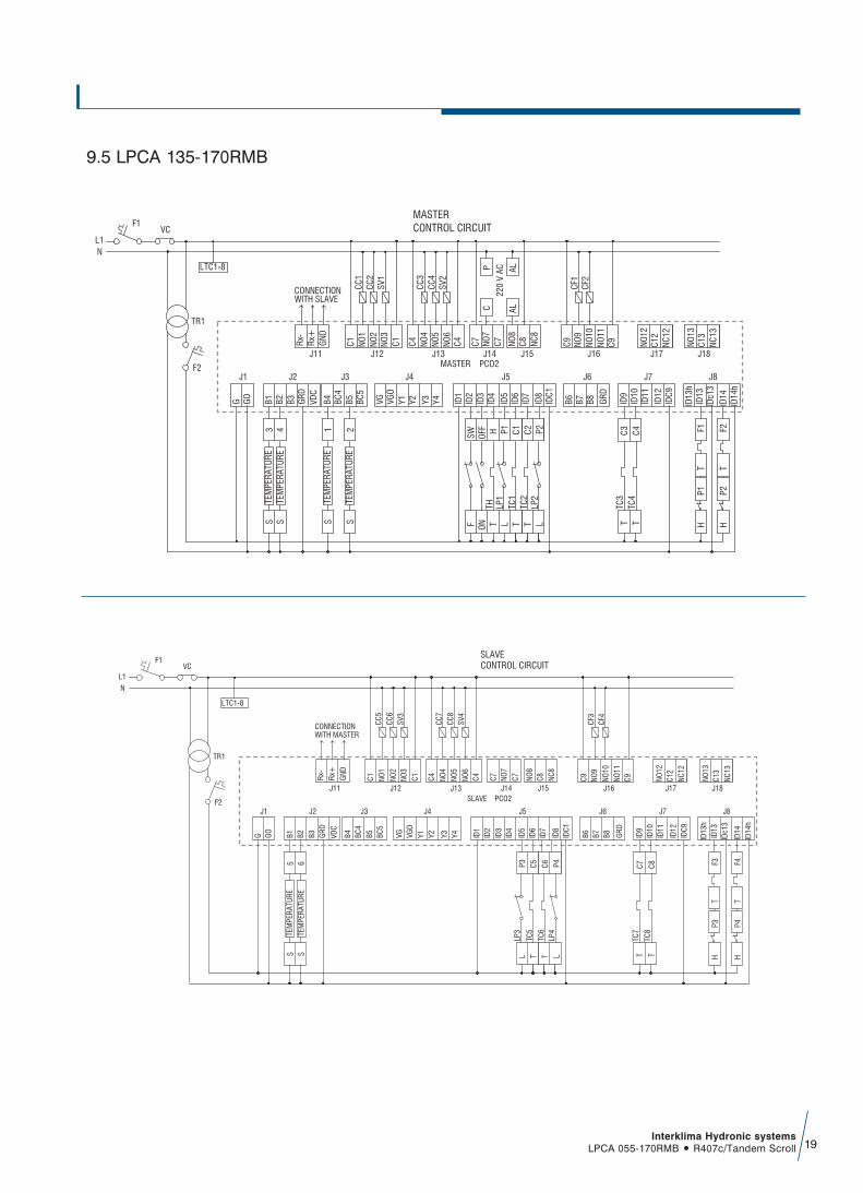
9.5 LPCA 135-170RMB
NCF1 CF2 CF3 CF4
CM3
V3U3
CC3
W4U4 V4W3
CM4
CC4
CC2
CH1 CH2
CC1
RVC
S T
PE
L1
L3N
L2
FC3 FC4
SM1 POWER CIRCUIT
CH1 CH2
N N
CH3
N
CH3
CC3
CH5
N
CH5
CC5
CM1
U1 V1 W1
CM2
W2U2 V2
FC1
CC1 CC2
FC2
FCH
CH4
N
CH4
CH6
N
CH6
CC6CC4
CM5
V5U5
CC5
W6U6 V6W5
CM6
CC6
FC5 FC6
SF1,2
FF1
SF3,4
FF2
UF1VF1WF1 UF2VF2WF2
SF5,6
FF3
UF3VF3WF3
CM7
V7U7
CC7
W8U8 V8W5
CM8
CC8
FC7 FC8
SF7,8
FF4
UF4VF4WF4
CH7
N
CH7
CC7
CH8
N
CH8
CC8
Interklima Hydronic systemsLPCA 055-170RMB ñ R407c/Tandem Scroll20
C-P PUMP COMMAND (220 V)T-H PUMP THERMAL PROTECTION (DRY CONTACT)F-SW DIFFERENTIAL WATER PRESSURE SWICTH (DRY CONTACT)AL-AL ALARM SIGNAL (N.O. CONTACT)ON-OFF REMOTE ON-OFF SWITCH (DRY CONTACT)
TC P H
220
V AC
SW ON OFFF AL AL
FEILD CONNECTIONS
220
V AC
HPC T P2 P2L
LTC1C1T HT C2 LP1 P1 HF OFF
ONSW 2SALAL 1 S SS 3 T4 F1 C3T T C4 LTC2
CH1
CH2
CH3
CH4
CH5
CH6
CH7
CH8
220
V FO
R A
NTI
FREE
ZE H
EATE
RS
(OPT
ION
AL)
PUM
P C
OM
MAN
D (
220V
AC)
PUM
P TH
ERM
AL P
RO
TEC
TIO
N
LIQ
UID
LIN
E SO
LEN
OID
VAL
VE C
IRC
UIT
1LI
QU
ID L
INE
SOLE
NO
ID V
ALVE
CIR
CU
IT 2
LIQ
UID
LIN
E SO
LEN
OID
VAL
VE C
IRC
UIT
3LI
QU
ID L
INE
SOLE
NO
ID V
ALVE
CIR
CU
IT 4
LOW
PR
ESSU
RE
PRES
SOST
AT C
IRC
UIT
1
CIR
CU
IT 2
CO
ND
ENSE
R C
OIL
TEM
PER
ATU
RE
SEN
SOR
S4
S 5C
IRC
UIT
3 C
ON
DEN
SER
CO
IL T
EMPE
RAT
UR
E SE
NSO
R
S5
S 6C
IRC
UIT
4 C
ON
DEN
SER
CO
IL T
EMPE
RAT
UR
E SE
NSO
R
S6
220
V °π
∞ ∆√
£∂ƒ
ªπ∫
√ ∆
√À
1Ô˘
™Àª
¶π∂
™∆∏
ENTE
RIN
G W
ATER
TEM
PER
ATU
RE
SEN
SOR
S1
CIR
CU
IT 1
FAN
S TH
ERM
AL P
RO
TEC
TIO
N
T F2C
IRC
UIT
2 F
ANS
THER
MAL
PR
OTE
CTI
ON
T F3C
IRC
UIT
3 F
ANS
THER
MAL
PR
OTE
CTI
ON
T F4C
IRC
UIT
4 F
ANS
THER
MAL
PR
OTE
CTI
ON
CO
MPR
ESSO
R 1
TH
ERM
AL P
RO
TEC
TIO
N
CO
MPR
ESSO
R 2
TH
ERM
AL P
RO
TEC
TIO
N
CO
MPR
ESSO
R 3
TH
ERM
AL P
RO
TEC
TIO
N
CO
MPR
ESSO
R 4
TH
ERM
AL P
RO
TEC
TIO
N
T C5C
OM
PRES
SOR
5 T
HER
MAL
PR
OTE
CTI
ON
T C6C
OM
PRES
SOR
6 T
HER
MAL
PR
OTE
CTI
ON
T C7C
OM
PRES
SOR
7 T
HER
MAL
PR
OTE
CTI
ON
T C8C
OM
PRES
SOR
8 T
HER
MAL
PR
OTE
CTI
ON
HIG
H P
RES
SUR
E PR
ESSO
STAT
CIR
CU
IT 1
LOW
PR
ESSU
RE
PRES
SOST
AT C
IRC
UIT
2
HIG
H P
RES
SUR
E PR
ESSO
STAT
CIR
CU
IT 2
LEA
VIN
G W
ATER
TEM
PER
ATU
RE
SEN
SOR
S2
CIR
CU
IT 1
CO
ND
ENSE
R C
OIL
TEM
PER
ATU
RE
SEN
SOR
S3
FLO
W S
WIT
CH
REM
OTE
SW
ITC
H O
N-O
FF
ALAR
M (
N.O
.CO
NTA
CT)
220
V F
OR
TH
ERM
AL C
OM
PRES
SOR
2LT
C3LT
C4 2
20 V
FO
R T
HER
MAL
CO
MPR
ESSO
R 3
220
V F
OR
TH
ERM
AL C
OM
PRES
SOR
4LT
C5LT
C6 2
20 V
FO
R T
HER
MAL
CO
MPR
ESSO
R 5
220
V F
OR
TH
ERM
AL C
OM
PRES
SOR
6LT
C7LT
C8 2
20 V
FO
R T
HER
MAL
CO
MPR
ESSO
R 7
220
V F
OR
TH
ERM
AL C
OM
PRES
SOR
8C
RAN
KCAS
E H
EATE
R C
OM
PRES
SOR
1C
RAN
KCAS
E H
EATE
R C
OM
PRES
SOR
2C
RAN
KCAS
E H
EATE
R C
OM
PRES
SOR
3C
RAN
KCAS
E H
EATE
R C
OM
PRES
SOR
4C
RAN
KCAS
E H
EATE
R C
OM
PRES
SOR
5C
RAN
KCAS
E H
EATE
R C
OM
PRES
SOR
6C
RAN
KCAS
E H
EATE
R C
OM
PRES
SOR
7C
RAN
KCAS
E H
EATE
R C
OM
PRES
SOR
8
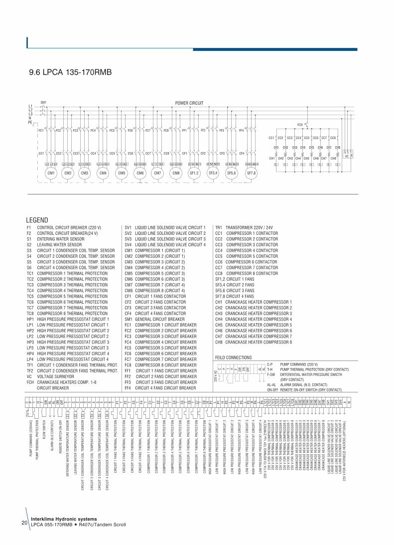
F1 CONTROL CIRCUIT BREAKER (220 V) F2 CONTROL CIRCUIT BREAKER(24 V)S1 ENTERING WATER SENSOR S2 LEAVING WATER SENSOR S3 CIRCUIT 1 CONDENSER COIL TEMP. SENSORS4 CIRCUIT 2 CONDENSER COIL TEMP. SENSORS5 CIRCUIT 3 CONDENSER COIL TEMP. SENSORS6 CIRCUIT 4 CONDENSER COIL TEMP. SENSORTC1 COMPRESSOR 1 THERMAL PROTECTION TC2 COMPRESSOR 2 THERMAL PROTECTIONTC3 COMPRESSOR 3 THERMAL PROTECTIONTC4 COMPRESSOR 4 THERMAL PROTECTION TC5 COMPRESSOR 5 THERMAL PROTECTION TC6 COMPRESSOR 6 THERMAL PROTECTION TC7 COMPRESSOR 7 THERMAL PROTECTION TC8 COMPRESSOR 8 THERMAL PROTECTION HP1 HIGH PRESSURE PRESSOSTAT CIRCUIT 1LP1 LOW PRESSURE PRESSOSTAT CIRCUIT 1 HP2 HIGH PRESSURE PRESSOSTAT CIRCUIT 2LP2 LOW PRESSURE PRESSOSTAT CIRCUIT 2HP3 HIGH PRESSURE PRESSOSTAT CIRCUIT 3LP3 LOW PRESSURE PRESSOSTAT CIRCUIT 3HP4 HIGH PRESSURE PRESSOSTAT CIRCUIT 4LP4 LOW PRESSURE PRESSOSTAT CIRCUIT 4TF1 CIRCUIT 1 CONDENSER FANS THERMAL PROT.TF2 CIRCUIT 2 CONDENSER FANS THERMAL PROT.VC VOLTAGE SURNEYORFCH CRANKCASE HEATERS COMP. 1-8 CIRCUIT BREAKER
LEGENDSV1 LIQUID LINE SOLENOID VALVE CIRCUIT 1SV2 LIQUID LINE SOLENOID VALVE CIRCUIT 2SV3 LIQUID LINE SOLENOID VALVE CIRCUIT 3SV4 LIQUID LINE SOLENOID VALVE CIRCUIT 4CM1 COMPRESSOR 1 (CIRCUIT 1)CM2 COMPRESSOR 2 (CIRCUIT 1)CM3 COMPRESSOR 3 (CIRCUIT 2)CM4 COMPRESSOR 4 (CIRCUIT 2)CM5 COMPRESSOR 5 (CIRCUIT 3)CM6 COMPRESSOR 6 (CIRCUIT 3)CM7 COMPRESSOR 7 (CIRCUIT 4)CM8 COMPRESSOR 8 (CIRCUIT 4)CF1 CIRCUIT 1 FANS CONTACTORCF2 CIRCUIT 2 FANS CONTACTORCF3 CIRCUIT 3 FANS CONTACTORCF4 CIRCUIT 4 FANS CONTACTORSM1 GENERAL CIRCUIT BREAKERFC1 COMPRESSOR 1 CIRCUIT BREAKER FC2 COMPRESSOR 2 CIRCUIT BREAKER FC3 COMPRESSOR 3 CIRCUIT BREAKER FC4 COMPRESSOR 4 CIRCUIT BREAKER FC5 COMPRESSOR 5 CIRCUIT BREAKER FC6 COMPRESSOR 6 CIRCUIT BREAKER FC7 COMPRESSOR 7 CIRCUIT BREAKERFC8 COMPRESSOR 8 CIRCUIT BREAKERFF1 CIRCUIT 1 FANS CIRCUIT BREAKERFF2 CIRCUIT 2 FANS CIRCUIT BREAKERFF3 CIRCUIT 3 FANS CIRCUIT BREAKERFF4 CIRCUIT 4 FANS CIRCUIT BREAKER
TR1 TRANSFORMER 220V / 24VCC1 COMPRESSOR 1 CONTACTORCC2 COMPRESSOR 2 CONTACTORCC3 COMPRESSOR 3 CONTACTORCC4 COMPRESSOR 4 CONTACTORCC5 COMPRESSOR 5 CONTACTORCC6 COMPRESSOR 6 CONTACTORCC7 COMPRESSOR 7 CONTACTORCC8 COMPRESSOR 8 CONTACTORSF1,2 CIRCUIT 1 FANSSF3,4 CIRCUIT 2 FANSSF5,6 CIRCUIT 3 FANSSF7,8 CIRCUIT 4 FANSCH1 CRANCKASE HEATER COMPRESSOR 1CH2 CRANCKASE HEATER COMPRESSOR 2CH3 CRANCKASE HEATER COMPRESSOR 3CH4 CRANCKASE HEATER COMPRESSOR 4CH5 CRANCKASE HEATER COMPRESSOR 5CH6 CRANCKASE HEATER COMPRESSOR 6CH7 CRANCKASE HEATER COMPRESSOR 7CH8 CRANCKASE HEATER COMPRESSOR 8
P3HH
IGH
PR
ESSU
RE
PRES
SOST
AT C
IRC
UIT
3
P3LLO
W P
RES
SUR
E PR
ESSO
STAT
CIR
CU
IT 3
SV1
SV2
SV3
SV4 ∞ ¡P4H
HIG
H P
RES
SUR
E PR
ESSO
STAT
CIR
CU
IT 4
P4LLO
W P
RES
SUR
E PR
ESSO
STAT
CIR
CU
IT 4
9.6 LPCA 135-170RMB

Interklima Hydronic systemsLPCA 055-170RMB ñ R407c/Tandem Scroll 21
1. Installation10.
The LPCA-RMB unit should be installed in a location that meetsthe following requirements:1. The foundation is strong enough to support the weight of the
unit, and the floor is flat to prevent vibration and noisegeneration.
2. The space around the unit is adequate for servicing and theminimum space air inlet and air outlet is available. If severalunits are being installed side by side in parallel, the minimumservice space between them must be taken into account.
3. There is no danger of fire due to leakage of inflammable gas.4. Ensure that water cannot cause any damage to the location in
case it drips out of the unit.5. Make sure that the air inlet and outlet of the unit are not
positioned towards the main wind direction.Frontal wind shalldisturb the operation of the unit.If necessary, use awindscreen to block the wind.
6. In heavy snowfall areas, select an installation site where snowshall not affect operation of the unit.
7. Make sure that the unit can be fixed directly on concrete.8. In order to avoid the transmission of vibration from the
operating unit to its carrying structure, the use of antivibrationmaterial to install under the supports of the unit isrecommended. It is suggested to install a rubber pad betweenthe points of support and the base of the unit, or springantivibration mounts under each point of support of the unit.
10.1 Selection of location - service space
2000mm
2000mm
4000mm
2000mm
2000mm
Interklima Hydronic systemsLPCA 055-170RMB ñ R407c/Tandem Scroll22
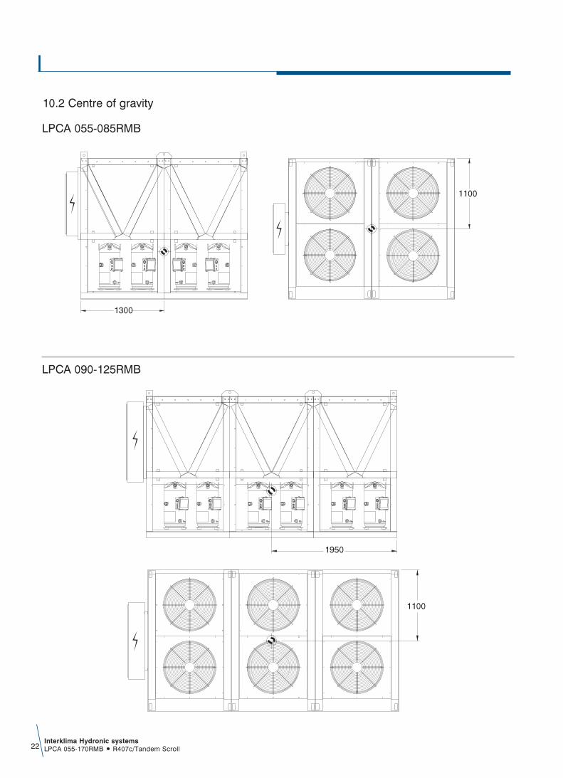
1300
1100
1950
1100
LPCA 055-085RMB
LPCA 090-125RMB
10.2 Centre of gravity

Interklima Hydronic systemsLPCA 055-170RMB ñ R407c/Tandem Scroll 23
2600
1100
LPCA 135-170RMB

1
3
8
5
162 9
3
1 25
46
8
5
10
12
11
4 5
7
5
7
13
14
5
15
Interklima Hydronic systemsLPCA 055-170RMB ñ R407c/Tandem Scroll24
Example with one central pump
ñ All field connections must be provided by a licensedtechnician and must comply with the relevant local andnational codes.
ñ Evaporator water connections should be made in accordancewith the unit outlook respecting the water inlet – and outlet.
ñ Water piping to be arranged so that the circulating pumpdischarges directly into the evaporator.
ñ Install a flow switch or water differential pressostat (standardcomponent) in the water outlet piping to prevent the unit fromoperating at a water flow, which is too low. A terminal isprovided in the switch box for the electrical connection of theflow switch in the control circuit.
ñ To avoid erosion, it is recommended to install a filter in thewater inlet pipe.
ñ It is essential to install a thermometer in the water inlet/ outletpipe to check temperatures.
ñ Provide heat insulation with suitable vapour barrier around thechilled water piping to prevent condensation and capacity loss.
ñ Provide drain connections at all low points of the system topermit complete drainage for maintenance and/ or shutdown
ñ Air vents should be provided at all high points in the systemlocated were they are easily accessible for servicing. Thewater inlet pipe is specially designed to obtain a complete airpurge of the evaporator
ñ Install an expansion tank on the suction side of the waterpump so that the water pressure on the pump suction will bepositive.
ñ To avoid frequent on/off operation of the compressor, aminimum water volume is required in the system (table 10.4)
ñ To assure proper operation of the unit, the water flow throughthe evaporator must be within the specified in (table 10.4)
10.3 Recommendations concerning the hydraulic circuit

31 2
5 6
5
14
13
7
15
5
12 11
88
1091621
3
4
4
76.1
6.16.1
5
55
5
55
555
5
55
Interklima Hydronic systemsLPCA 055-170RMB ñ R407c/Tandem Scroll 25
Example with internal loop pump and external zoon pumps
NOTES1. Flexible2. Thermometer3. Manometer4. Air vent5. Shut of valve6. Pump (primary circuit)6.1 Pump (secondary circuit)7. Water filter8. Drainage9. Flow switch (optional)10. Balancing valve11. Buffer tank12. Electric resistance13. Automatic make up water valve14. Expansion membrane15. Check valve16. Safety valve

Interklima Hydronic systemsLPCA 055-170RMB ñ R407c/Tandem Scroll26
3,5-4 bar
17-19 bar
4-5 bar
21-23 bar
5,5-6 bar
24-26 bar
low pressure
high pressure
Minimum(outdoor temp. 15ÔCDB) (leaving water temp 6ÔC)
Nominal(outdoor temp. 35ÔCDB)(leaving water temp, 7ÔC)
Maximum(outdoor temp. 38ÔCDB)
(leaving water temp, 25ÔC)
Cooling mode(region)
To ensure proper operation of the unit, a minimum water volumeis required in the system and the water flow must be within theoperation range as specified in the table.
It is important to check the high and low pressure of therefrigerant circuit to ensure the proper operation of the unitand to guarantee that the rated output shall be obtained.
Attention:The pressures measured shall vary between a maximumand minimum value, depending on the water andambient temperatures at the moment of measurement.
10.4 Watercharge, flow and quality
10.5 Operating pressure of the refrigerant circuit
112912881445160417941931216824052690289132073587
LPCA 055RMBLPCA 060RMBLPCA 070RMBLPCA 075RMBLPCA 085RMBLPCA 090RMBLPCA 100RMBLPCA 115RMBLPCA 125RMBLPCA 135RMBLPCA 150RMBLPCA 170RMB
Minimumwater
volume (l)
147881685518914209642345625286283663145535188378194193746912
Minimumwater flow
(l/h)
3237036911414354597651428553676216168955771258288791934
102839
Nominalwater flow
(l/h)
38915440004977350000510006654369000710009260199524
103000104000
Maximumwater flow
(l/h)
Items to be controlled:
PH AT 25ÔC
∂lectrical conduct (mS/m) at 25ÔC
Chloride ion (mg CI-/I)
Sulfate ion (mg SO 2/4/I
M-alkalinity (ph 4.8) (mg SO3/I)
Total hardness (mg CaCO3/I )
Calcium hardness (mg CaCO3/I)
Silica ion (mg SiO2/I
Items to be referred to:
Iron (mg Fe/I)
Copper (mg Cu/I)
Sulfide ion (mg S2-/I)
Amonium ion (mg NH+4/I
Remaining chloride (mg CI/I)
Free carbide (mg SO2/I)
Stability index
6.8 - 8.0
below 30
below 50
below 50
below 50
below 70
below 50
below 30
below 1.0
below 1.0
Not detectable
below 0.3
below 0.25
below 0.4
-
6.8 - 8.0
below 30
below 200
below 50
below 50
below 70
below 50
below 30
below 0.3
below 0.1
Not detectable
below 0.1
below 0.3
below 4.0
-
7.0 - 8.0
below 30
below 30
below 30
below 50
below 70
below 50
below 30
below 1.0
below 1.0
Not detectable
below 0.1
below 0.1
below 0.4
-
7.0 - 8.0
below 30
below 30
below 30
below 50
below 70
below 50
below 30
below 0.3
below 1.0
Not detectable
below 0.1
below 0.3
below 4.0
-
ItemsCirculatingwater 20C Supply water Circulating
water 20C-60C Supply water
Tendencyif out of criteria
Evaporator water Heated water
corrosion + scale
corrosion + scale
corrosion
corrosion
scale
scale
scale
scale
corrosion + scale
corrosion
corrosion
corrosion
corrosion
corrosion
corrosion + scale
Be sure the water quality is in accordance with the specificationsbelow
NOTESThe above tables are purelyindicative and non-binding

Interklima Hydronic systemsLPCA 055-170RMB ñ R407c/Tandem Scroll 27
User interface LPCA 055-085RMBThe interface on the front panel of the instrument can be used tocarry out all the operations connected to the use of the instrument,and in particular to:
Set operating mode Check the state of resourcesRespond to alarm situations
10.6.1 KeysSelects operating mode (heating/defrost refersto LPCA-H heat pump models only):
If the heating mode is enabled, each time thekey is pressed the following sequence occurs:Stand-by cooling heating stand by
If cooling mode is enabled:heating Stand-by cooling heating stand byIn menu mode, this key acts as a SCROLL UPor UP key (increasing value).
Resets alarms, and turns the instrument onand off. Press once to reset all manually resetalarms not currently active.
Hold down the key for 2 seconds to turn theinstrument from on to off or vice versa. When it isoff, only the decimal point remains on the display.In menu mode this key acts as a SCROLL DOWNor DOWN key (decreasing value).
Pressing the “mode” and “on-off” keys at thesame time.
If you press both keys at the same time andthen release within 2 seconds, you shall moveone level deeper in the display menu. If you press both keys for more than 2 secondsyou shall move one level up.If you are currently viewing the lowest level inthe menu and you press both keys and releasewithin 2 seconds, you shall go up one level.
10.6.2.2 LedLed 1 compressor 1 (circuit 1).ON if compressor 1 is active.OFF if compressor 1 is off.Rapid BLINK if safety timing is in progress.Slow BLINK if compressor is currently set to defrost (heat pump version).
Led 2 compressor 2 (circuit 1).ON if compressor 2 is active.OFF if compressor 2 is not active.Rapid BLINK if safety timing is in progress.low BLINK if compressor 2 is currently defrosting.
Led 3 compressor 3 (circuit 2).ON if compressor 3 is active (compressor2).OFF if compressor 3 is not active.Rapid BLINK if safety timing is in progress.Slow BLINK if compressor 3 is defrosting.
Led 4 compressor 4 (circuit 2).ON if compressor 4 is active.OFF if compressor 4 is not active.Rapid BLINK if safety timing is in progress.Slow BLINK if compressor 4 is defrosting.
10.6.2 Displays10.6.2.1 DisplayNormal display shows:
ñ Regulation temperature in tenths of degreescelsius with a decimal point, or in degreesfahrenheit without a decimal point.
ñ The alarm code, if at least one alarm is active. Ifmultiple alarms are active, the one with greaterpriority shall be displayed, according to the Tableof Alarms.
ñ If temperature control is not analogue anddepends on the status of a digital input (ST1 orST2 configured as digital inputs), the “On” or“Off” label shall be displayed, depending onwhether temperature control is active or not.
ñ When in menu mode, the display depends on thecurrent position; labels and codes are used tohelp the user identify the current function.
ñ Decimal point: when displaying hours of operation,indicates that the value must be multiplied x 100.
10.6 Digital controler
Front panel of the instrument
1 2
3 4
1
2
3
4
Interklima Hydronic systemsLPCA 055-170RMB ñ R407c/Tandem Scroll28
24
S + -
S + -
26
25
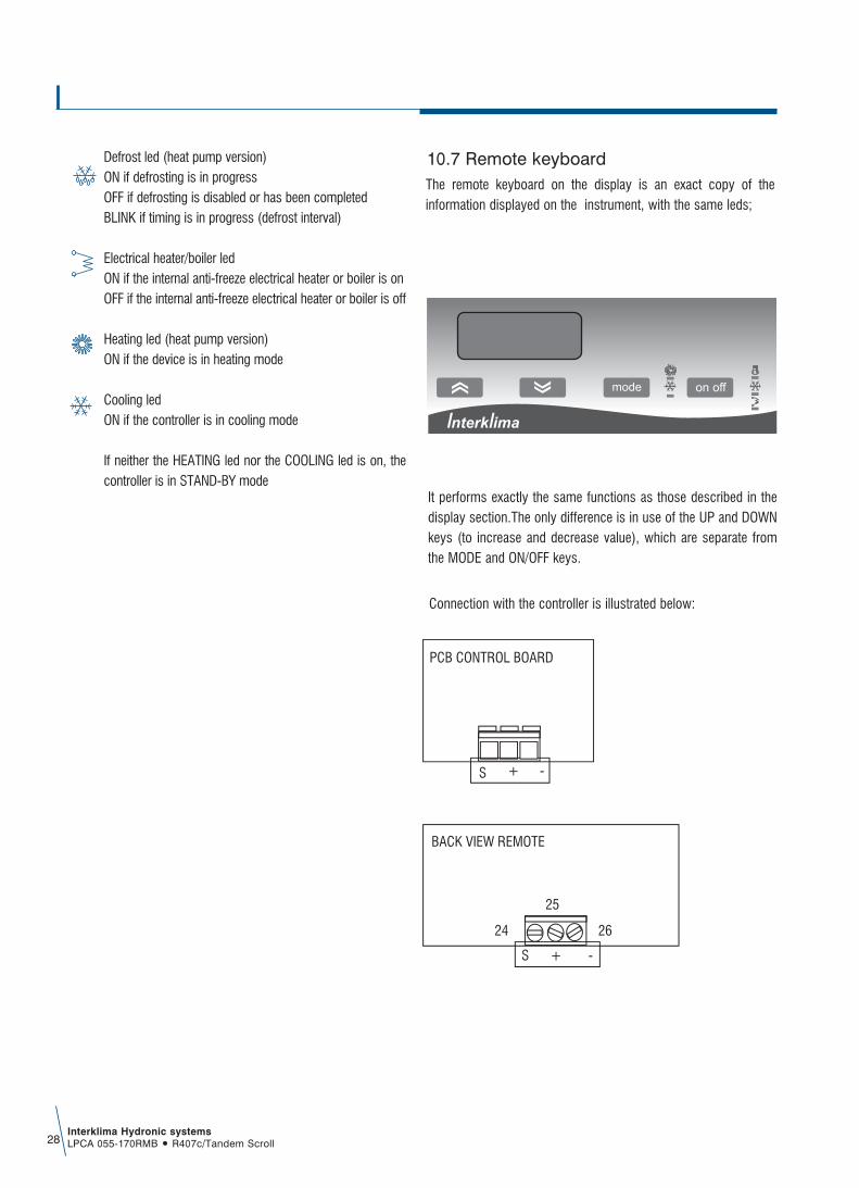
PCB CONTROL BOARD
BACK VIEW REMOTE
The remote keyboard on the display is an exact copy of theinformation displayed on the instrument, with the same leds;
Connection with the controller is illustrated below:
It performs exactly the same functions as those described in thedisplay section.The only difference is in use of the UP and DOWNkeys (to increase and decrease value), which are separate fromthe MODE and ON/OFF keys.
10.7 Remote keyboardDefrost led (heat pump version)ON if defrosting is in progressOFF if defrosting is disabled or has been completedBLINK if timing is in progress (defrost interval)
Electrical heater/boiler ledON if the internal anti-freeze electrical heater or boiler is onOFF if the internal anti-freeze electrical heater or boiler is off
Heating led (heat pump version)ON if the device is in heating mode
Cooling ledON if the controller is in cooling mode
If neither the HEATING led nor the COOLING led is on, thecontroller is in STAND-BY mode

Interklima Hydronic systemsLPCA 055-170RMB ñ R407c/Tandem Scroll 29
ñ Displays the values measured by the probes.
ñ Displays the values relating to the maintenance of the devices(working hours and operating hourcounter reset.
ñ Accesses the group of screens for printer management.
ñ Displays the status of inputs and outputs(both digital and analogue.
ñ Allows the display/programming of the clock.
ñ Allows the Set-Point setting.
ñ Allows the various operating parameters to be set(safety parameters, thresholds).
ñ By pressing simultaneously these buttons you access the unit configuration (number ofinstruments connected to the pCO2, scale setting, probe calibration etc.).
ñ Displays the version of the application program and other information.
ñ 1. ON-OFF: switches the unit on or off. The green LED that lights up in the button shows if the machine is turned on.
2. Alarm button: used for displaying or manually resetting the alarms and for silencing the buzzer. If the button light up (red), at least one alarm has been detected.
3. The arrow pointing upwards to manage the currently displayed screen and to set the values of the control parameters (not back-lit).
4. The arrow pointing downwards to manage the currently displayed screen and to set the values of the control parameters (not back-lit).
5. Enter button: to confirm the set data. The button is constantly back-lit (yellow) indicating the presence of mains power.
The interface on the front panel of the instrument can be used tocarry out all the operations connected to the use of the instrument,and in particular to:ñ Set operating modeñ Respond to alarm situationsñ Check the state of resources
10.8 User interface LPCA 090-170RMB

Interklima Hydronic systemsLPCA 055-170RMB ñ R407c/Tandem Scroll30
The supply, transport to jobsite, installation, commissioning andstart up of an air cooled water chiller with the following technicalcharacteristics. The unit shall be factory assembled, charged withR407C refrigerant and factory tested.The capacity of the unit shall be no less than:
Ambient air temperature (DB) ÆCEntering water temperature ÆCLeaving water temperature ÆC
The unit shall operate unhindered within 6 to 15ÆC water outlettemperature, 3.5 to 7ÆC water temperature difference and 5 up to45ÆC ambient air temperature.The structural requirements shall be the following:
UNIT HOUSINGThe unit housing shall be fabricated from heavy gauge galvanizedsteel sheets, formed to ensure maximum rigidity that shallguarantee and preserve the unit operation during the years. Allmetal parts after fabrication shall be degreased phosphatized, andelectrostatically powder coated with epoxy- polyester RAL 9002coating of a thickness of 60-70 m. The corrosion resistancetreatment must successfully withstand a salt spray test of 500hours, according to ASTM B- 117. All components shall beassembled exclusively together using bolts, without welding. Theunit shall have removable access panels, designed in such amanner as to permit easy access to internal compartments onlyby authorized personnel. Electrical and electronic equipment andcomponents for proper unit operation shall be located in a weatherproof (IP 55) electrical panel with access via only a special key.
COMPRESSORSShall be of the hermetic tandem scroll type, with low noise andvibration levels, specially optimized for use with R407c refrigerant.They shall be equipped with a crank case electrical heater, toseparate refrigerant and oil when the unit is not operating. Theyshall also include internal protection against overloading orelectrical spikes. The compressors shall be mounted on specialant vibration rubber mounts to absorb and eliminate any vibrationthat can be generated from the unit base.
AIR HEAT EXCHANGERThe air hear exchangers shall be manufactured from seamlesscopper tubes and an outside diameter of 9.52mm (3/8'') of highquality according to ASTM B 280, and shall be inner grooved toachieve optimized heat transfer between refrigerant and tube. The
fins shall be manufactured from aluminium. The fins shall becontinuous across the heat exchanger and the fin surface shall bewaffle formed and louvered so as to increase the fin rigidity andheat transfer. The combination of internally grooved copper tubingand louvered fins must result in a heat transfer performance 30%superior to that of a conventional coil.The assembly of the finned pack shall be achieved by mechanicalexpansion in such a way as to form a perfect mechanical bondwith the fins. For his purpose, the fin holes shall have a peripheralextrusion (collar).
WATER HEAT EXCHANGERAll units shall be equipped with a Shell and Tube water –directexpansion type evaporator that has multiple cooling circuits, one foreach independent refrigerant circuit. The casing shall be of steel andthe internal tubes of copper. There shall be an air vent valve, drainvalve, probes for water temperature sensors, differential pressureswitch and the whole heat exchanger shall be wrapped in a heavyinsulation material appropriate for external installation.
AIR HEAT EXCHANGER FANS The unit shall be equipped with axial type fans, three phase, and 6poles, internally protected against potential over heating, low noiseand suitable for outdoor installation. The design of the blades andinlet cones shall be aerodynamic, and the fan motor assemblyshall be perfectly, statically and dynamically balanced allowing acompletely vibration free operation. The fan motor assembly shallhave a protective grid against accidental contact with movingparts according to ISO. The fan motor shall be of the external rotortype with permanently lubricated bearings that do not requireservicing. The motor shall be aerodynamically shaped so as not tointerfere with the airflow. The unit shall have the ability to beequipped with a continuous linear fan speed regulation controlaccording to coil temperature.
Microprocessor controllerAll units shall be equipped with an electronic programmablecontrol system. This shall allows complete management of all thefunctions of the unit and ensures protection of all vital parts. Itshall have a diagnostics function, permitting easy andstraightforward understanding of all the possible failures andmalfunctions of the unit. All functions and indicators shall appearon the LCD screen. Over 150 programmable parameters shalloffer complete unit management.
Guide specifications11.
LPCA 055-170RMB
Interklima Hydronic systemsLPCA 055-170RMB ñ R407c/Tandem Scroll 31
Critical parameters that shall require control are:ñ Start-up / shut down time of compressor.ñ Time delay.ñ Protection against multiple start-up.ñ Water pump time delay in reference to compressor
operation.ñ Inlet/Outlet water temperature.ñ Air heat exchanger temprature.
Controlled operational parametersñ Water temperature adjustment in the inlet side during
summer operation*.ñ Water outlet temperature adjustment in summer operation**.ñ Compressor capacity control.
Controlled fault parametersñ Low suction pressure per refrigerant circuit.ñ High discharge pressure per refrigerant circuit.ñ Compressor overload.ñ Fan motor overload.ñ Water pump overload.ñ Flow switch fault.ñ Water sensor error due to bad contact or destruction.ñ Error reading in water outlet low temperature.ñ Compressor operating hour reading.
In addition the control shall also includeñ Self diagnostic error of all electronic control sensors.ñ Remote on/ off switch.ñ Remote alarm indication capability.ñ History of operation points and fault codes**.ñ Password access code.
Refrigerant circuitThe units shall have multiple refrigerant circuits depending on thesize, one per tandem compressor.
Each circuit shall consist of the following:ñ Thermal expansion valve.ñ Filter drier with a replaceable core.ñ Shut off valves.ñ 2-way solenoid valve.ñ Sight glass.ñ High and low pressure gauges for each refrigerant circuit,
easily viewed.
ñ Service valves.ñ Unit protection shall be provided by a high pressure switch
with manual reset, low pressure protection is a low-pressureswitch with auto reset.
ñ Flexible refrigerant pipe on the compressor discharge andsuction lines to avoid vibration and noise.
Note:The consultant may if required ad the below metioned optionalaccessories / fuctions.
Optional accessories
Microprocessor controller optionsñ BMS module interface kit for Bacnet, Lon Works and Trend
connection**.ñ BMS interface kit for Modbus connection.ñ Connection via internet using a device converting the Carel
protocol to 10Mb/s TCP/IP ethernet protocol**.ñ Possibility to send and receive messages using a GSM
modem**.ñ Communication card through RS232 / RS485 serial ports.ñ Extended memory card for up to five thousands
messages**.ñ Extended memory card 1&2 MB**.ñ Parallel chiller operation with standard controller for units
with a maximum of eight compressors*.ñ Microprocessor parameter reprogramming card.ñ Compressor running current**.ñ Self diagnostic and adaptive control**.
Other unit accessories/optionñ R407c or R22 refrigerant.ñ Condenser fins made of copper or prepainted aluminum, and
Blygold treatment for corrosion protection.ñ Glycol for chilled water temperature down to –5oC.ñ Continuous linear fan speed regulation.ñ High pressure relief valve on compressor discharge.ñ A-meter, V-meter.ñ Compressor noise reduction jacket.ñ Electrical board ventilation fan.ñ Water heat exchanger antifreezing electrical heater.ñ Other custom built options upon request.
* For models 055-085
** For models 090 – 170

Products are manufactured in ISO 9001:2000certified factories. ISO 9001:2000 pertains to quality
assurance regarding design, development,manufacturing and installation of products
as well as to services related to the product.
INTERKLIMA PRODUCTS ARE DISTRIBUTED BY:
EG
B-µ
-3-9
-06/
06
Specifications subject to change without notice
Interklima units comply with the European regulations thatguarantee the safety of the product
Engineering Data 2006