ls-tun-001-a vck30, 40) limited slip differential (uck30, 40 and vck30, 40) ls-tun-001-a limited...
TRANSCRIPT
TUNDRA (UCK30, 40 andVCK30, 40)
LS-TUN-001-A
Limited Slip Differential
Page 1 of 17Rev: A © TRD 12/06/01
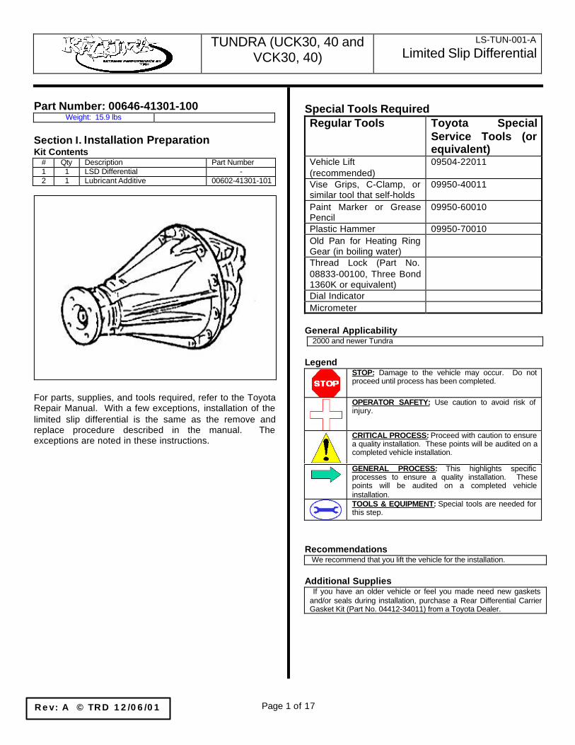
Part Number: 00646-41301-100Weight: 15.9 lbs
Section I. Installation PreparationKit Contents
# Qty Description Part Number1 1 LSD Differential -2 1 Lubricant Additive 00602-41301-101
For parts, supplies, and tools required, refer to the ToyotaRepair Manual. With a few exceptions, installation of thelimited slip differential is the same as the remove andreplace procedure described in the manual. Theexceptions are noted in these instructions.
Special Tools RequiredRegular Tools Toyota Special
Service Tools (orequivalent)
Vehicle Lift(recommended)
09504-22011
Vise Grips, C-Clamp, orsimilar tool that self-holds
09950-40011
Paint Marker or GreasePencil
09950-60010
Plastic Hammer 09950-70010Old Pan for Heating RingGear (in boiling water)Thread Lock (Part No.08833-00100, Three Bond1360K or equivalent)Dial IndicatorMicrometer
General Applicability2000 and newer Tundra
LegendSTOP: Damage to the vehicle may occur. Do notproceed until process has been completed.
OPERATOR SAFETY: Use caution to avoid risk ofinjury.
CRITICAL PROCESS: Proceed with caution to ensurea quality installation. These points will be audited on acompleted vehicle installation.
GENERAL PROCESS: This highlights specificprocesses to ensure a quality installation. Thesepoints will be audited on a completed vehicleinstallation.TOOLS & EQUIPMENT: Special tools are needed forthis step.
Recommendations We recommend that you lift the vehicle for the installation.
Additional Supplies If you have an older vehicle or feel you made need new gasketsand/or seals during installation, purchase a Rear Differential CarrierGasket Kit (Part No. 04412-34011) from a Toyota Dealer.

TUNDRA (UCK30, 40 andVCK30, 40)
LS-TUN-001-A
Limited Slip Differential
Page 2 of 17Rev: A © TRD 12/06/01
Section II. Vehicle Disassembly ProcedurePlease follow the Toyota Repair Manual instructionssteps 1 through 17 (beginning on page SA-95) toremove the factory differential carrier assembly. Thenotes in this section will highlight specific points.Figure 1 shows an exploded view of the major partsyou will be working with.
1. Lift the vehicle (a chassis lift is recommended)and leave the parking brake off (Figure 2).
Figure 1.
Figure 2.

TUNDRA (UCK30, 40 andVCK30, 40)
LS-TUN-001-A
Limited Slip Differential
Page 3 of 17Rev: A © TRD 12/06/01
2. Drain the differential case (Figure 3).
3. Remove both rear wheels and brake drums.Note the use of bolts (8 x 1.25) to push the drumaway from the hub in Figure 4.
Figure 3.
Figure 4.

TUNDRA (UCK30, 40 andVCK30, 40)
LS-TUN-001-A
Limited Slip Differential
Page 4 of 17Rev: A © TRD 12/06/01
4. Pinch the flexible brake line above the differentialhousing just upstream of the “T” where the solidlines start (Figure 5). Use tape or cloth to preventdamage to the flexible line.
5. Remove the brake lines (including the parkingbrake cord) from the drums and plug thempromptly to minimize fluid loss (this will makebleeding them at the end much easier).
6. Remove the four (4) 14mm nuts that hold thehubs to the rear axle housing (Figure 6).
Figure 5.
Figure 6.

TUNDRA (UCK30, 40 andVCK30, 40)
LS-TUN-001-A
Limited Slip Differential
Page 5 of 17Rev: A © TRD 12/06/01
7. Pull the half shafts and hubs out and set onground (Figure 7). Have an assistant hold a ragagainst the shaft as it is removed to keep thework area clean.NOTICE: Take care to pull the shaft straight outand not rub against the oil seal to preventdamage which may cause leaks afterreassembly.
8. Place matchmarks on the differential andpropeller shaft flanges (Figure 8).
Figure 7.
Figure 8.

TUNDRA (UCK30, 40 andVCK30, 40)
LS-TUN-001-A
Limited Slip Differential
Page 6 of 17Rev: A © TRD 12/06/01
9. Remove the 4 nuts, bolts, and washers thatconnect the propeller shaft to the differentialcarrier (Figure 9). Detach the propeller shaft fromthe rear differential carrier. On 2WD models,remove the shaft retainer before detaching thepropeller shaft.
10. Remove the 10 nuts that hold the rear differentialcarrier to the rear axle housing (Figure 10).Remove the rear differential carrier.
Check that the rear differential carrier has beencompletely drained and that the flow of oil hasstopped.
DO NOT damage the installation surface.
Figure 9.
Figure 10.
TUNDRA (UCK30, 40 andVCK30, 40)
LS-TUN-001-A
Limited Slip Differential
Page 7 of 17Rev: A © TRD 12/06/01
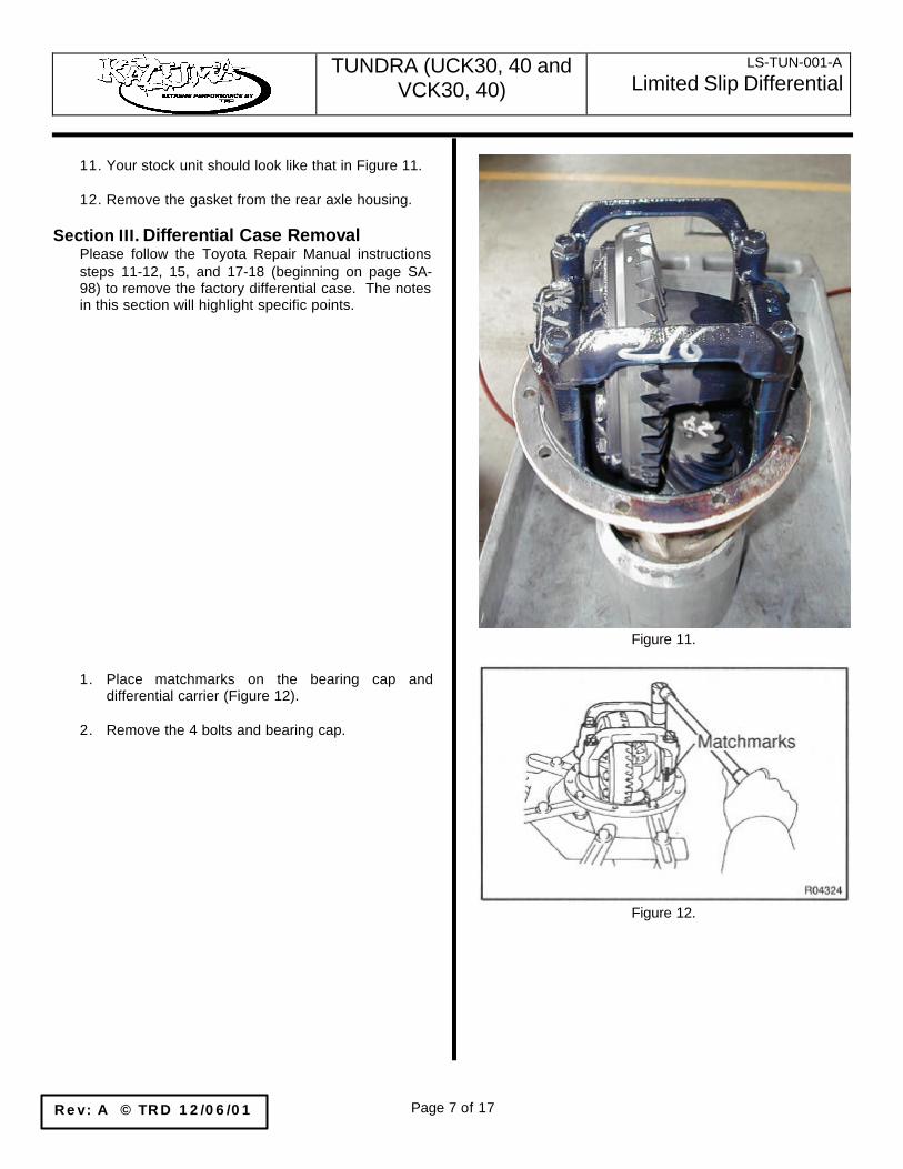
11. Your stock unit should look like that in Figure 11.
12. Remove the gasket from the rear axle housing.
Section III. Differential Case RemovalPlease follow the Toyota Repair Manual instructionssteps 11-12, 15, and 17-18 (beginning on page SA-98) to remove the factory differential case. The notesin this section will highlight specific points.
1. Place matchmarks on the bearing cap anddifferential carrier (Figure 12).
2. Remove the 4 bolts and bearing cap.
Figure 11.
Figure 12.

TUNDRA (UCK30, 40 andVCK30, 40)
LS-TUN-001-A
Limited Slip Differential
Page 8 of 17Rev: A © TRD 12/06/01
3. Using the Special Service Tool (SST) 09504-22011 and a plastic hammer, remove the 2 sidebearing plate washers (Figure 13).
HINT: Measure the plate washer thickness and writeit down.
4. Remove the differential case with the bearingouter races from the carrier.
HINT: Tag the bearing outer races to show thelocation for reassembling.
5. Remove the drive pinion from differential carrier.
6. Remove the 12 bolts that secure the ring gear(Figure 14).
7. Using a plastic hammer, tap on the ring gear toseparate it from the differential case.
8. Using the SSTs (09950-40011 & 09950-60010),remove the 2 side bearings from the differentialcase (Figure 15).
HINT: Fix the claws of the SST to the notch in thedifferential case.
Figure 13.
Figure 14.
Figure 15.

TUNDRA (UCK30, 40 andVCK30, 40)
LS-TUN-001-A
Limited Slip Differential
Page 9 of 17Rev: A © TRD 12/06/01
Section IV. Differential Case AssemblyPlease follow the Toyota Repair Manual instructionssteps 1-4, 8-13 (beginning on page SA-101) to installthe new limited slip differential case. The notes inthis section will highlight specific points.
1. Using the SSTs (09950-60010 & 09950-70010)and a press, install the 2 side bearings into thedifferential case (Figure 16).
2. Clean the contact surfaces of the differential caseand ring gear.
3. Heat the ring gear by placing in boiling water(Figure 17).
4. Carefully take the ring gear out of the boilingwater.
5. After the moisture on the ring gear hascompletely evaporated, quickly install the ringgear to the differential case.
6. After the ring gear has cooled significantly, torquethe set bolts to which the thread lock has beenapplied.Thread lock: Part No. 08833-00100, ThreeBond 1360K or equivalent.Torque: 92 ft-lbf
7. Place the 2 bearing outer races on theirrespective bearings. Make sure the right and leftraces are not interchanged.
8. Install the differential case into the carrier andinstall the plate washers to where there is no playin the bearing.
9. Align the matchmarks on the bearing cap and thecarrier.
10. Install and torque the 4 bolts to 83 ft-lbf.
Figure 16.
Figure 17.

TUNDRA (UCK30, 40 andVCK30, 40)
LS-TUN-001-A
Limited Slip Differential
Page 10 of 17Rev: A © TRD 12/06/01
11. Using a dial indicator, measure the runout of thering gear (Figure 18).Maximum runout: 0.0020 in.
12. Remove the bearing cap.
13. Install the plate washer on the ring gear back side(Figure 19).
HINT: Make sure that the ring gear has backlash.
Figure 18.
Figure 19.

TUNDRA (UCK30, 40 andVCK30, 40)
LS-TUN-001-A
Limited Slip Differential
Page 11 of 17Rev: A © TRD 12/06/01
14. Tap on the ring gear with a plastic hammer sothat the washer fits to the bearing (Figure 20).
15. Using a dial indicator, while holding thecompanion flange, measure the ring gearbacklash (Figure 21).Backlash: 0.006 – 0.010 in. (do not use thenumber in the manual)
16. Select a plate washer for the back side ring gearso that the backlash is within the required range(Figure 22).
Figure 20.
Figure 21.
Figure 22.

TUNDRA (UCK30, 40 andVCK30, 40)
LS-TUN-001-A
Limited Slip Differential
Page 12 of 17Rev: A © TRD 12/06/01
17. Select a ring gear teeth side plate washer so thatthere is no clearance between the outer race andcase (Figure 23).
18. Remove the 2 plate washers that were selectedin steps 16 and 17 and the differential case.
19. Install the plate washer into the ring gear backside of the carrier.
20. Place the other plate washer onto the differentialcase together with the outer race, and install thedifferential case with the outer race into thecarrier (Figure 24).
21. Tap on the ring gear with a plastic hammer sothat the washers fit to the bearing.
22. Using a dial indicator, while holding thecompanion flange, measure the ring gearbacklash (Figure 25).Backlash: 0.006 – 0.010 in. (do not use thenumber in the manual)
If the backlash is not within the specified value, adjustit by either increasing or decreasing the thickness ofwashers on both sides by an equal amount.HINT: There should be no clearance between theplate washer and the case.Make sure that there is a ring gear backlash.
Figure 23.
Figure 24.
Figure 25.
TUNDRA (UCK30, 40 andVCK30, 40)
LS-TUN-001-A
Limited Slip Differential
Page 13 of 17Rev: A © TRD 12/06/01
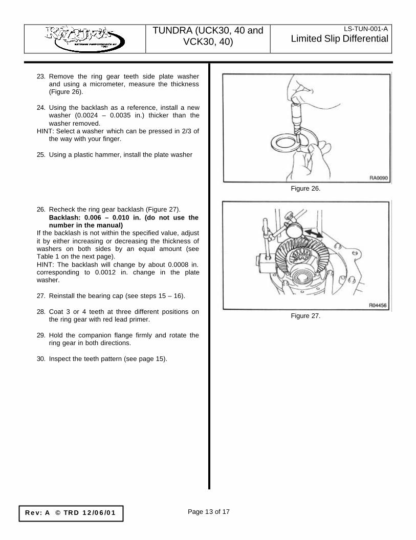
23. Remove the ring gear teeth side plate washerand using a micrometer, measure the thickness(Figure 26).
24. Using the backlash as a reference, install a newwasher (0.0024 – 0.0035 in.) thicker than thewasher removed.
HINT: Select a washer which can be pressed in 2/3 ofthe way with your finger.
25. Using a plastic hammer, install the plate washer
26. Recheck the ring gear backlash (Figure 27).Backlash: 0.006 – 0.010 in. (do not use thenumber in the manual)
If the backlash is not within the specified value, adjustit by either increasing or decreasing the thickness ofwashers on both sides by an equal amount (seeTable 1 on the next page).HINT: The backlash will change by about 0.0008 in.corresponding to 0.0012 in. change in the platewasher.
27. Reinstall the bearing cap (see steps 15 – 16).
28. Coat 3 or 4 teeth at three different positions onthe ring gear with red lead primer.
29. Hold the companion flange firmly and rotate thering gear in both directions.
30. Inspect the teeth pattern (see page 15).
Figure 26.
Figure 27.

TUNDRA (UCK30, 40 andVCK30, 40)
LS-TUN-001-A
Limited Slip Differential
Page 14 of 17Rev: A © TRD 12/06/01
TUNDRA (UCK30, 40 andVCK30, 40)
LS-TUN-001-A
Limited Slip Differential
Page 15 of 17Rev: A © TRD 12/06/01
TUNDRA (UCK30, 40 andVCK30, 40)
LS-TUN-001-A
Limited Slip Differential
Page 16 of 17Rev: A © TRD 12/06/01
Section V. Differential Case InstallationPlease follow the Toyota Repair Manual instructionsstep 1 (beginning on page SA-110) to install the newlimited slip differential case. The notes in this sectionwill highlight specific points.
1. Install a new gasket.
2. Install the differential carrier assembly (with thelimited slip differential inside) with 10 washersand nuts.
NOTICE: Be careful not to damage the installationsurface.
Torque: 54 ft-lbf
Section VI. Reassembly of VehiclePlease follow the Toyota Repair Manual instructionssteps 2 through 4 (beginning on page SA-110) toinstall the new limited slip differential case. The notesin this section will highlight specific points.
1. Align the matchmarks on the propeller shaft anddifferential flanges and connect the flanges withthe 4 bolts, washers and nuts.
2. Torque the 4 bolts to 54 ft-lbf.
3. Install new O-Ring to rear axle housing.
4. Install rear axle shaft assemblies. Torque to 51ft-lbf.
5. Connect brake lines and parking brake cable.Torque to 11 ft-lbf.
6. Install a new gasket and replace the brake drumsand the wheels.

TUNDRA (UCK30, 40 andVCK30, 40)
LS-TUN-001-A
Limited Slip Differential
Page 17 of 17Rev: A © TRD 12/06/01
7. Replace the Drain Plug and tighten to 49 ft-lbs.Remove the Filler Plug. Pour all of the limitedslip differential lubricant additive into thedifferential. Fill the differential with Hypoid GearOil API GL-5
Oil Viscosity:Above 0ºF: SAE 90Below 0ºF: SAE 80W or 80W – 90
Capacity:2WD: 3.33 US quarts4WD: 3.12 US quarts
Stop filling when the level of the oil reaches within0.200” of the bottom of the filler hole. Replacethe Filler Plug and tighten to 49 ft-lbs.
8. Bleed rear brake lines.