lsm-9506...the mitutoyo laser scan micrometer lsm-9506 is both a precision optical instrument and a...
TRANSCRIPT

LSM-9506
Laser ScanMicrometer
User's Manual
No.99MBC032A3SERIES No.544
Read this User’s Manual thoroughly
before operating the instrument. After reading,
retain it close at hand for future reference.

No. 99MBC032A
CONVENTIONS USED IN USER'S MANUALSafety Precautions
To operate the instrument correctly and safely, Mitutoyo manuals use various safety signs (Signal
Words and Safety Alert Symbols) to identify and warn against hazards and potential accidents.
The following signs indicate general warnings:
DANGER
Indicates an imminently hazardous situation which, if not avoided, will result in serious
injury or death.
WARNING
Indicates a potentially hazardous situation which, if not avoided, could result in serious
injury or death.
CAUTION
Indicates a potentially hazardous situation which, if not avoided, may result in minor or
moderate injury or property damage.
The following signs indicate specific warnings or prohibited actions, or indicate a mandatory action:
Alerts the user to a specific hazardous situation. The given example means “Caution,
risk of electric shock”.
Prohibits a specific action. The given example means “ Do not disassemble”.
Specifies a required action. The given example means “Ground”.
i

No. 99MBC032A
CONVENTIONS USED IN USER'S MANUALOn Various Types of Notes
The following types of notes are provided to help the operator obtain reliable measurement data
through correct instrument operation.
IMPORTANT • An important note is a type of note that provides information essential to the completion
of a task. You cannot disregard this note to complete the task.
• An important note is a type of precaution, which if neglected could result in a loss of
data, decreased accuracy or instrument malfunction/failure.
NOTE A note emphasizes or supplements important points of the main text. A note supplies infor-
mation that may only apply in special cases (e.g.. Memory limitations, equipment configura-
tions, or details that apply to specific versions of a program).
TIP A tip is a type of note that helps the user apply the techniques and procedures described in
the text to their specific needs.
It also provides reference information associated with the topic being discussed.
Mitutoyo assumes no liability to any party for any loss or damage, direct or indirect,
caused by use of this instrument not conforming to this manual.
Information in this document is subject to change without notice.
© Copyright Mitutoyo Corporation. All rights reserved.
NOTES FOR EXPORTINGIf you export this product, contact the nearest Mitutoyo sales office in advance.
ii

No. 99MBC032A
PRECAUTIONS
1. Safety Precautions
CAUTION
The Mitutoyo Laser Scan Micrometer LSM-9506 uses a laser beam.
1) “This LSM conforms to the US CDRH regulations in 21 CFR 1040 for a class IIlaser product.”
2) Do not look directly into the laser beam. (Never look into the emission window,even when no light is emitted.)
3) Do not observe the laser beam directly through optical equipment, such as amagnifying lens.
4) When measuring flat objects with mirror finishes, avoid looking at the reflection onthe surface.
5) Close the beam shutter when not in use.
6) Do not open the emission unit cover except for servicing. The output powerwhen the cover is open is about 1.2mW.
7) Do not remove the “CAUTION” or “WARNING” labels.
8) The laser beam does not harm human skin when irradiating.
9) “CAUTION – Use of controls or adjustments or performance of procedures otherthan those specified herein may result in hazardous radiation exposure.”
CAUTIONLASER LIGHT-DO NOT
STARE INTO BEAM
1mW-650nmCLASS II LASER PRODUCT
2. If an optional device is to be connected to this system, make sure that the optional device isalso turned off.
3. Firmly tighten the screws of the cable connectors and interfaces to ensure shielding.
4. Do not touch the terminals of the connectors, otherwise contact may be poor.
5. Positively ground the Display Unit.
6. An error display may appear during operation. However, it may not always indicate a fault. Ifan error display appears, consult the “Maintenance and Inspection” section.
Do not open the covers provided on the emission unit and reception unit.
iii

No. 99MBC032A
SAFETY PRECAUTION LABELS LOCATED ON LSM-9506
CAUTIONLASER LIGHT-DO NOT
STARE INTO BEAM
1mW-650nmCLASS II LASER PRODUCT
Beam attenuator
CAUTION-Laser Lightwhen open
DO NOT STARE INTOBEAM
CAUTION-Laser Lightwhen open
DO NOT STARE INTOBEAM
AVOID EXPOSURE-LASER RADIATION ISEMITTED FROM THIS APERTURE
CAUTION-Laser Lightwhen open
DO NOT STARE INTOBEAM
Complies_with_21_CFR_1040.10Mitutoyo_Corporation1-20-1,_Sakado,Takatsu-Ku,_Kawasaki-Shi,Kanagawa_213,_JAPANManufactured:
LASER EMISSION INDICATOR
LASER EMISSION
iv

No. 99MBC032Av
INSTALLING CONDITIONSThe Mitutoyo Laser Scan Micrometer LSM-9506 is both a precision optical instrument and aprecision electric instrument, and it is designed for indoor use. Therefore, it must be carefullyinstalled and the following conditions must be taken into consideration to attain the highestpossible accuracy.
1. VibrationInstall this unit if possible in a place where it will not be subject to vibration. If this unit isused for a long period of time in an environment where there are significant vibrations, theprecision parts in this unit may be affected, resulting in the deterioration of measuringaccuracy.
If this unit has to be used in an environment where vibration is significant, measures such asthe laying of a vibration damping rubber pad under the unit must be applied to reduce theeffect of vibration.
2. DustDust and airborne particles at the installation site adversely affect optical parts including theprotective glass and electronic parts of the Measuring Unit. Place this unit in a place with aslittle dust and as few airborne particles as possible.
3. Direct sunlightIf this unit is subjected to direct sunlight, the heat may deform this unit and affect themeasuring accuracy.
If this unit must be placed by a window where it will be subjected to direct sunlight, protectthe unit by shading it.
4. Ambient temperature and humidityThis unit must be operated in an environment where the temperature is between 0 and 40˚Cand the humidity is between 35 and 85% RH. Avoid installing this unit where there issignificant temperature or humidity change.
Significant temperature and humidity changes may reduce measuring accuracy.
WARRANTYIn the event that the Mitutoyo Laser Scan Micrometer (LSM) should prove defective inworkmanship or material, within one year from the date of original purchase for use, it willbe repaired or replaced, at our option, free of charge upon its prepaid return to us.
If the unit fails or is damaged because of the following causes it will be subject to a repairchange, even if it is still under warranty.
1. Failure or damage due to inappropriate handling or unauthorized modification.2. Failure or damage due to transport, droppage, or relocation of the machine after
purchase.3. Failure or damage due to fire, salt, gas, abnormal voltage, or natural catastrophe.
This warranty is effective only where the machine is properly installed and operated follow-ing this manual.

No. 99MBC032A vi
CONTENTSCONVENTIONS USED IN USER'S MANUAL ................................................................. iNOTES FOR EXPORTING ............................................................................................... iiPRECAUTIONS ...............................................................................................................iiiSAFETY PRECAUTION LABELS LOCATED ON LSM-9506........................................ ivINSTALLING CONDITIONS .............................................................................................vWARRANTY......................................................................................................................v
1. INTRODUCTION ................................................................................................... 1-11.1 Outline ........................................................................................................... 1-11.2 Foreword ....................................................................................................... 1-11.3 Nomenclature ................................................................................................ 1-2
1.3.1 Display Unit ....................................................................................... 1-21.3.2 Measuring Unit .................................................................................. 1-3
2. SETUP .................................................................................................................. 2-12.1 Unpacking and Acceptance Check ............................................................... 2-12.2 Connecting the Cables ................................................................................. 2-12.3 Preliminary Checks ....................................................................................... 2-32.4 Initializing the LSM-9506 .............................................................................. 2-5
3. DISPLAYS AND KEY OPERATIONS .................................................................. 3-13.1 Outline of the Operation Modes ................................................................... 3-1
3.1.1 Outline of the Operation Modes ....................................................... 3-13.1.1.1 Overview ................................................................................. 3-13.1.1.2 Setting the segment ............................................................... 3-33.1.1.3 Measurement interval (measurement time) ........................... 3-4
3.1.2 Outline of the Operation Modes ....................................................... 3-53.1.2.1 Basic setup mode ................................................................... 3-63.1.2.2 Calibration mode .................................................................... 3-63.1.2.3 Measuring condition setup mode ........................................... 3-63.1.2.4 Other setup mode ................................................................... 3-63.1.2.5 Statistic display mode ............................................................. 3-63.1.2.6 Measurement mode................................................................ 3-7
3.2 Techniques and Terminology of Setup Functions ........................................ 3-93.2.1 Program ............................................................................................ 3-93.2.2 Basic setup ....................................................................................... 3-93.2.3 Function setup ................................................................................ 3-103.2.4 Setups according to the property of each workpiece ..................... 3-10
3.2.4.1 Transparent object (Workpiece that transmits light) ............ 3-103.2.5 Latch (holding) of the displayed value ........................................... 3-123.2.6 Automatic measurement with an edge specification ...................... 3-133.2.7 GO/NG judgment ............................................................................ 3-143.2.8 Abnormal data elimination .............................................................. 3-163.2.9 Offset/Zero-set ................................................................................ 3-173.2.10 Mastering ........................................................................................ 3-173.2.11 Reference value .............................................................................. 3-183.2.12 Data output conditions .................................................................... 3-183.2.13 Automatic workpiece detection <OD detection method, Position
detection method> .......................................................................... 3-19

No. 99MBC032Avii
3.2.14 Group judgment .............................................................................. 3-213.2.15 Recording the amount of light ........................................................ 3-22
3.3 Outline of the Display Contents .................................................................. 3-233.3.1 Display unit ..................................................................................... 3-233.3.2 Data display unit ............................................................................. 3-23
3.4 Outline of Key Operations .......................................................................... 3-253.4.1 Description of key functions ........................................................... 3-273.4.2 Example key operations ................................................................. 3-31
4. SETTING UP THE MEASURING CONDITIONS ................................................. 4-14.1 Basic Setup ................................................................................................... 4-1
4.1.1 Outline of the basic setup procedure ............................................... 4-24.1.2 Description of each mode ................................................................. 4-3
4.1.2.1 Selecting and setting the function in the B0 mode ................ 4-4a. Setting the resolution (Guidance: RES) ............................ 4-4b. Setting the number of blank-out digits (Guidance: BLN) .. 4-4c. Putting a comma after the thousandths digit
(Guidance: (,)) ................................................................... 4-5d. Setting the buzzer function (Guidance: BUZZER) ............ 4-5e. Setting the display latch timer (Guidance: LATCH) .......... 4-6
4.1.2.2 Selecting and setting the function in the B1 mode ................ 4-7a. Setting the output function in the ready state
(Guidance: D.OUT)............................................................ 4-7b. Selecting the display message if Err-0 occurs
(Guidance: ERR-0 D) ........................................................ 4-7c. Selecting the display message at the start of
measurement (Guidance: RUN D) .................................... 4-7d. Selecting the averaging method (Guidance: AVG.M) ....... 4-8e. Setting the GO/NG judgment method
(Guidance: JDG.M)............................................................ 4-8f. Setting whether the target value is copied to the
reference value (Guidance: COPY) .................................. 4-84.1.2.3 Selecting and setting the function in the B2 mode ................ 4-9
a. Setting the workpiece type (Guidance: WORK.P) ............ 4-9b. Setting the simultaneous measurement
(Guidance: PROG) ............................................................ 4-9c. Selecting the method of specifying segments
(Guidance: SEG) ............................................................... 4-94.1.2.4 Selecting and setting the function in the B3 mode .............. 4-10
a. Setting the abnormal value elimination function(Guidance: ADE) ............................................................. 4-10
b. Setting the automatic workpiece detecting function(Guidance: AWDT) .......................................................... 4-10
c. Setting the number of scans (Guidance: SCAN) ............ 4-10d. Setting the group judgment (Guidance: GTJ) ................. 4-11e. Setting the group judgement output
(Guidance: GTJ D) .......................................................... 4-114.1.2.5 Selecting and setting the function in the B4 mode .............. 4-12
a. Setting the use of RS-232C port(Guidance: RS-232C) ...................................................... 4-12

No. 99MBC032A viii
b. Setting the RS-232C communication baud rate(Guidance: BAUD) ........................................................... 4-12
c. Setting the RS-232C communication data bits(Guidance: LENGTH) ...................................................... 4-12
d. Setting the RS-232C communication parity bit(Guidance: PARITY) ........................................................ 4-13
e. Setting the delimiter for communication(Guidance: DELIMT)........................................................ 4-13
f. Setting the RS-232C line control(Guidance: CONTRL) ...................................................... 4-13
4.1.2.6 B5: Reserved ........................................................................ 4-144.1.2.7 Selecting and setting the function in the B6 mode .............. 4-14
a. Setting the use of DCU (Guidance: DCU) ...................... 4-144.2 Calibration ................................................................................................... 4-15
4.2.1 Calibration gages and gage stand ................................................. 4-154.2.2 Entering the calibration mode......................................................... 4-15
4.3 Positioning a Gage or a Workpiece ............................................................ 4-194.4 How to read-in the amount of light ............................................................. 4-194.5 Setting Up the Functions ............................................................................ 4-20
4.5.1 Outline of the function setup mode ................................................ 4-204.5.2 Outline of each function setup mode ............................................. 4-224.5.3 Function setup mode ...................................................................... 4-23
4.5.3.1 F0: Setting the segment ....................................................... 4-234.5.3.2 F1: Setting the measurement interval
(measurement time) ............................................................. 4-254.5.3.3 F2: Setting the GO/NG judgment criteria ............................. 4-274.5.3.4 F3: Setting the reference value ............................................ 4-314.5.3.5 F4: Setting the offset value .................................................. 4-324.5.3.6 F5: Setting the data output conditions ................................. 4-344.5.3.7 F6: Setting the sample measurement .................................. 4-354.5.3.8 F7: Automatic workpiece detection setting .......................... 4-364.5.3.9 F8: Setting the group judgment ............................................ 4-374.5.3.10 Confirming the function setup contents ................................ 4-38
5. MEASUREMENT MODE ...................................................................................... 5-15.1 Outline of the Measurement Mode ............................................................... 5-1
5.1.1 Setup in the measurement mode ..................................................... 5-15.1.1.1 Setup operation from the arrow key ....................................... 5-25.1.1.2 Setup that can be made directly from each setup item key .. 5-4
5.2 Other Functions ............................................................................................ 5-55.2.1 Key lock ............................................................................................ 5-55.2.2 Displaying the measuring position .................................................... 5-5
5.3 Applied Measurement ................................................................................... 5-65.3.1 OD measurement of a precision-machined workpiece .................... 5-65.3.2 Measurement of magnet coil wire that runs at high speed.............. 5-75.3.3 Measurement of the lead pitch of a multiple-pin IC ......................... 5-85.3.4 Applied Measurement with Offset/Zero-Set Functions ................... 5-105.3.5 Sample measurement ..................................................................... 5-135.3.6 Applied measurement with automatic workpiece detection ........... 5-155.3.7 Applied measurement on a stepped round bar .............................. 5-17

No. 99MBC032A
6. INTERFACE UNIT ................................................................................................ 6-16.1 RS-232C Interface ........................................................................................ 6-1
6.1.1 Specifications .................................................................................... 6-16.1.2 Connections ...................................................................................... 6-36.1.3 Printer interface ................................................................................ 6-5
6.1.3.1 Setting the printer ................................................................... 6-56.1.3.2 Setting the LSM-9506 ............................................................. 6-6
6.1.4 RS-232C commands ........................................................................ 6-66.1.5 List of commands ............................................................................. 6-86.1.6 List of response commands if an error occurs ............................... 6-106.1.7 Format of response commands ...................................................... 6-116.1.8 Other commands ............................................................................ 6-126.1.9 Details of command descriptions ................................................... 6-136.1.10 An example Program of RS-232C Communication ....................... 6-21
6.2 Digimatic Output Unit interface ................................................................... 6-226.2.1 Method of use ................................................................................. 6-226.2.2 I/O specifications ............................................................................ 6-236.2.3 Timing chart .................................................................................... 6-246.2.4 Data format ..................................................................................... 6-25
7. INSPECTION AND MAINTENANCE .................................................................... 7-17.1 Display Unit ................................................................................................... 7-1
7.1.1 Display check .................................................................................... 7-17.1.2 Cleaning method ............................................................................... 7-1
7.2 Measuring Unit .............................................................................................. 7-27.2.1 Cleaning optical parts ....................................................................... 7-2
7.2.1.1 Checking method of the reception signal using an oscilloscope .... 7-27.2.2 Replacement of protection glass ...................................................... 7-2
7.3 Error Messages and Remedies .................................................................... 7-37.4 Troubleshooting and Remedies .................................................................... 7-47.5 Fuse replacement ......................................................................................... 7-5
8. SPECIFICATIONS ................................................................................................ 8-18.1 Specifications ................................................................................................ 8-2
9. RESTRICTIONS ASSOCIATED WITH THE COMBINATION OF FUNCTIONS,TABLES OF THE BASIC SETUP MODES ......................................................... 9-19.1 Restrictions Associated with the Particular Combination of Functions ........ 9-19.2 List of Setup Modes ...................................................................................... 9-3
9.2.1 List of basic setup modes ................................................................. 9-39.2.2 List of calibration functions ............................................................... 9-49.2.3 Reading in the amount of light ......................................................... 9-49.2.4 List of function setup modes ............................................................ 9-5
SERVICE NETWORK
ix

1
1 - 1No. 99MBC032A
This chapter describes the Laser Scan Micrometer (LSM) models andnomenclature of the Display unit and the Measuring unit.
INTRODUCTION
1.1 OutlineThis system is an accurate, non-contact measurement system capable of measuring workpiecedimensions at a high speed using a highly directional scanning laser beam.
This non-contact optical measuring system is capable of measuring workpieces which aredifficult to measure with conventional measuring instruments. It performs simple andaccurate measurement of brittle or elastic objects, objects at high temperature, objects whichmust be kept clean, and soft objects which may be deformed and suffer dimensional changesunder the measuring forces used.
1.2 Foreword
WARNING
The Measuring Unit uses a laser. For safe operation, carefully read and follow the“Safety Precautions on Use of Laser” section described in the user’s manual that issupplied with each Measuring Unit.
The LSM-9506 is classified into two types, the mm/E type and mm/inch type. This User’sManual explains about the mm/E type. In case of using the mm/inch type, read this User’sManual with replacing the “E” indication with “inch (in)”.

1 - 2 No. 99MBC032A
1.3 NomenclatureThis section gives the name of each part in the LSM system.
1.3.1 Display Unit
(1) Front panel
MASTEROFFSET
S.PRPRINT
SHIFT
READ
H.CAL
L.CAL
STATS.E
A.CLM.CL
LOCKUNIT
SETC.RUNRUN
C9
6
3
+/-
8
5
2
7
4
1
•0
LIMIT
REF
ENT
LOCK CAL OFFSET S.E DUAL
Mitutoyo LASER SCAN MICROMETER LSM-9506
PROG.
Status indicator LEDs (lit/unit)
Data display
Workpiece Position indicator LEDOperation keys
Laser Emission indicator LED
Power switch
–NG GO +NG RUN BUSYLASER EMISSION
(2) Displays and keys
MASTEROFFSET
S.PRPRINT
SHIFT
READ
H.CAL
L.CAL
STATS.E
A.CLM.CL
LOCKUNIT
SETC.RUNRUN
C9
6
3
+/-
8
5
2
7
4
1
•0
LIMIT
REF
ENT

1 - 3No. 99MBC032A
1. INTRODUCTION
(3) Rear panel
AC power inlet
RS-232C connectorFoot switch
Remote interlock connectorDigimatic output connector
Scanning signal connector
Serial number labelFuse holder
GND terminal
TIP The terminal located at the left end of the power input terminal and marked (by asymbol or ) is the grounding terminal to keep the potential of signal line of thisunit equal with other instrument connected. It is used to enhance resistance againstelectrical interference.
1.3.2 Measuring Unit
(1) Measuring Unit
Shutter
Emission unit Reception windowReception unit
Display unit
Emission window

1 - 4 No. 99MBC032A
MEMO
2
2 - 1No. 99MBC032A
This chapter describes the connection between the Display Unit andMeasuring Unit.
SETUP
2.1 Unpacking and Acceptance CheckYour LSM has been thoroughly inspected prior to shipment. The mechanical, electrical, andoptical systems are guaranteed to operate properly.
Unpack the package and check that the main unit is not damaged, and all the accessorieslisted are present.
Contact Mitutoyo if anything is damaged or missing.
2.2 Connecting the CablesMake sure that the power switch is turned off (turn the key switch counterclockwise to alignwith “O”, then pull it out), then connect the cables according to the following procedure.
Step 1: Connecting the power cord and GND lead wireConnect the supplied power cord to the AC connector on the rear panel of the mainunit. Also be sure to ground the main unit with the GND lead wire for improvedresistance to noise.
Grounding must be done properly:Connect the supplied grounding wire, after cutting it to the minimum length, to thegrounding terminal provided on the Display Unit. This unit operates as a precisionanalog processor and, at the same time, a high-speed calculation unit. To enhanceresistance against electrical interference and to increase safety, do not neglectgrounding.

2 - 2 No. 99MBC032A
Step 2: Checking the remote interlock connectorMake sure that the short-circuiting pin is inserted into the “REMOTE INTERLOCK”connector on the rear panel of the Display Unit. If this short-circuiting pin is notinserted, laser emission is disabled, even if the power switch is on.
To emergency stop laser emission, refer to the following diagram.
Switch ON: Laser emission ONSwitch OFF: Laser emission OFF
(Manufacturer: Sato Parts)Applicable connector: PJ-25V, 3mA
Short-circuiting pin
Switch
Step 3: Connecting the interfaceFor information about the procedure used to connect the interface, refer to Section6.1, “RS-232C Interface” and Section 6.2, “Digimatic Output Unit Interface”.
IMPORTANT Note the following when making cable connections.Always make connection or disconnection with the power cord unplugged. In addi-tion, before connecting to the interface make sure that the power to all other unitsconnected or to be connected are also off.
Do not disassemble this unit. This unit is a precision instrument. Should it be disas-sembled by the user, its accuracy can not be guaranteed even within the term of itswarranty. And, there will be a charge for repairs.
Observe the following to avoid electric shock.1. Do not remove the protective cover on which the seal is stuck to. Otherwise, an
electric shock may result.2. Do not remove the seal, shown at the left.

2 - 3No. 99MBC032A
2. SETUP
2.3 Preliminary ChecksThe necessary connections should be completed by following the procedure described in theprevious chapter. Simplified operation checks are described here.
Step 1: Fully open the lens cap and shutter of the Measuring Unit.Fully open the lens caps and beam shutters of both the emission unit and receptionunit to ready the laser beam for emission.The lens caps should be completely removed, and the shutters should be as shown inthe diagram below.
Emission window
Shutter window
Shutter
If the shutter is closed If the shutter is open
Step 2: Power on• Turn the power key switch on the Display Unit clockwise until it is in the I
(power on) position and the power is on.• This unit enters the self check mode and all the LEDs and segments turn on. They
will turn off shortly, and eights will be displayed in the upper display section.
When is displayed across the upper display section, the unit will turn
off shortly. This is followed by the self check on the lower display section.
PROG PROGPROG
• In the lower display section eights will appear sequentially from the left toright.
• After is displayed across the lower display section, it willturn off shortly.
PROG PROG
• Measurement is started.The LASER EMISSION LED turns on and the BUSY LED starts flashing toindicate the measurement has started from the ready state.
PROGSince the objective segment has been set to“SEG 1” at the factory, the displayed measure-ment shows the laser scanning range of theMeasuring Unit.
Here, the Display Unit is found to be normalbecause the scanning range is displayed.Proceed to Chapter 3, “FUNCTIONS ANDKEY OPERATIONS”, to custom set up eachfunction.

2 - 4 No. 99MBC032A
PROG• An error may be displayed at this stage,however, the display at the right is not actuallyan error. Check the shutter of the MeasuringUnit.For information about other errors that may result refer to Section 7.3, “ErrorMessages and Remedies”.

2 - 5No. 99MBC032A
2. SETUP
2.4 Initializing the LSM-9506After making sure that this unit is operating normally, initialize the LSM-9506.
The initialization procedure is as follows:
Step 1: Turn off the power.
Step 2: Turn on the power while holding down the C key.Hold down the C key for approximately 2 seconds, even after the power is on.
PROGStep 3: When the self check has been completed, thedisplay shown at the right will appear. To initial-ize, press the ENT key. When the initializationprocess has been completed, the display restoresthe initial conditions that existed just after thepower on.To abort initialization press a key other than the ENT key or turn the power off.In the former case the initialization process will be aborted and the initial display atpower-on will be restored.
IMPORTANT Initialization will clear all the customer setup data and will restore the factory-setups.Customize the setups again as necessary.

2 - 6 No. 99MBC032A
MEMO

3
3 - 1No. 99MBC032A
This Display Unit is provided with many useful functions that can becustomized according to the user's needs.
This chapter describes these functions and key operations.
DISPLAYS AND KEYOPERATIONS
3.1 Outline of the Operation Modes
3.1.1 Outline of the Operation Modes
In order for the user to understand the measurement principle of the LSM, the followingparagraphs describe about the system block diagram, segments (measurement positions) andmeasurement interval (measurement time).
3.1.1.1 Overview
Unlike light emitted from natural sources, a laser provides extremely fine, rectilinear beamswhich do not diffuse (coherent light beams).
Using the properties of the laser beam, the Mitutoyo Laser Scan Micrometer (LSM) moves ascanning laser beam over the workpiece and determines its dimensions by measuring theduration in which the beam is obstructed by the workpiece.
RS
Photoelectric element(reset signal generation)
ttt
Foot switch
Segmentselection circuit
Gate Edge signal
Edge signal
Counter
RS-232CData displayKeyboard
CPU
Motor driving pulse Clock pulse
ROM RAM
Digimatic Out-put Unit I/F
RS
Amplifier
Condenser lens
Workpiece
Receptiondevice S
Motor Colimator lens
Laser power source Semiconductor laser
Polygon mirror
Polygon mirror
MP
Emission unit Reception unit

3 - 2 No. 99MBC032A
The configuration of the system is shown in the block diagram described in the previouspage. A laser beam emitted from the laser oscillator is directed at the polygon mirror whichrotates at high speed and is synchronized by clock pulses. The laser beam that is reflected bythe polygon mirror is then collimated by the collimator lens towards the workpiece. As thepolygon mirror rotates, this horizontal beam scans the workpiece and the beam not obstructedby the workpiece will reach the photoelectric element through the condenser lens and inducean output voltage in the photoelectric element. The output voltage will change according tothe duration over which the laser beam is obstructed. Counting pulses generated during thatperiod are used to determine the dimension of the obstructed portion. This data is sent to theCPU for processing and the dimensions are displayed digitally.
Consequently, either the dimensions of the workpiece (shadowed areas) or workpiececlearances (highlighted areas) can be determined by specifying the segments to be measured.
TIP In the above system block diagram, the laser beam passed through the collimatorlens is made parallel and, at the same time, stopped down so that the beam diam-eter is minimized at the measurement position.

3 - 3No. 99MBC032A
3. DISPLAYS AND KEY OPERATIONS
3.1.1.2 Setting the segment
Set the objective portion of a workpiece to be measured.
The highlighted and shaded portions created when the laser scans over the workpiece arecontrolled with each assigned number. In the basic setup a selection must be made from oneof two cases: case where there are 1 to 4 highlighted and shaded sections, and case wherethere are 1 to 127 similar sections. In the former case the portions are controlled through thesegment number, and are simply called segments. In the latter case the portions are controlledby the edge number (edge number is between 1 and 255) and called edges. Edge numbersequal to or greater than 256 are not available.
SEG2
SEG1
SEG3
SEG5
SEG7
SEG4
SEG6
Segment specification
Dire
ctio
n of
lase
r sc
anni
ng
Highlight 1
Highlight 2
Shade 2
Highlight 3
Highlight 4
Shade 3
Shade 1
EDGE255
EDGE254
EDGE5
EDGE4
EDGE3
EDGE2
EDGE1
EDGE256
Edge specification
Dire
ctio
n of
lase
r sc
anni
ng
Highlight 1
Highlight 2
Highlight 128
Highlight 127
Shade 127
Shade 2
Shade 1
• A maximum of 4 highlighted sections and amaximum of 3 shaded sections can be measured.
• Multiple segments can be specified at the sametime.
• Specify segments 1 to 3 for a transparent object.
• A maximum of 127 highlighted sections and amaximum of 127 shaded sections can be mea-sured.
• Always specify the start edge and finish edgenumbers. These two edges can be either contin-ued or separated. However, they must not beidentical.
• Edge numbers can not be specified for a transpar-ent object.
• If automatic measurement is specified in the basicsetup, intervals, outside diameters, or gapsbetween the same shape of multiple pins can beautomatically measured.

3 - 4 No. 99MBC032A
3.1.1.3 Measurement interval (measurement time)
A measurement interval (measurement time) varies depending on the averaging method andthe number of scans selected for the measurement data.
There are two types of averaging method: the arithmetical average and the moving average.Select the one best suited for the user’s purpose.
1) Arithmetical average
• If a moving workpiece is measured, the OD of the workpiece is determined by averagingthe measured data taken from each section (a: first measurement, b: second measurement,.... n: nth measurement) of the workpiece the specified number of averaging times, asshown below.
ba n
. . .
second measurementfirst measurement
nth measurement
Moving directionMoving workpiece
• One of the following number of averaging times can be selected: 1, 2, 4, 8, ....1024, 2048.(If extra fine wire measurement is specified in the basic setup, the number of averagingtimes can be selected from between 16 and 2048.)
• This is suitable for measuring a still object or the run-out of rollers, etc.
2) Moving average
In the moving average method, a measurement interval identical to that in the arithmeticalaverage is divided into finer sections such as a1 (1st measurement), a2 (2nd measurement), -- - , an (nth measurement). Each measurement is performed almost in parallel. If, for ex-ample, the number of averaging times is set to 512, the first measurement requires theamount of time that corresponds to 512 scans. However, for the second measurement onward,only the time for 16 scannings is required. With respect to a workpiece with a changing OD,this method provides data with smooth variation because of the many pieces of data, and alsoquickly detects the trend of workpiece OD variation.
. . .
. . .
Moving directionMoving workpiece
Measurement with
arithmetical averaging
Measurement with
arithmetical averaging
an measurement
a1
a2
an
a1 measurement
a2 measurement
Output of an measurement
Output of a2 measurement
Output of a1 measurement
• One of the following number of scans can be selected: 32, 64, 128, ....1024, 2048.• This method is suitable for the feedback control of wire drawing machines and extruding
machines.

3 - 5No. 99MBC032A
3. DISPLAYS AND KEY OPERATIONS
3.1.2 Outline of the Operation Modes
The LSM system has the following modes:
1: Basic setup mode, 2: Calibration mode, 3: Function setup mode, 4: Other setup mode, 5:Statistical result display mode, and 6: Measurement mode.
SETSET
SET
C
C
SHIFT
SHIFT
LOCKUNITUNIT
LOCKUNIT
LOCK
S.PRPRINT
S.PRPRINT
ENT ENT
C.RUNRUN
RUN
• Latch timer
• @@@
•
• ( , , )
H.CAL L.CAL
H.CAL L.CAL
MASTEROFFSET
LIMIT
LIMIT
REFENT
SET•
• , , , MASTEROFFSET
REFSHIFT
6 : Measurement mode
Ready state
Measurement in progress(Program being executed)• Single-run measurement• Continuous-run• measurement
Measured data display(Latched display)
SETPower ON +
Power ON
Error check
1 : Basic setup mode
3 : Function setup mode
2 : Calibration mode
5 : Statistical result display mode
4: Other setup mode
( )
( )
( , )
( )
, ,
,

3 - 6 No. 99MBC032A
3.1.2.1 Basic setup mode
• This mode is used to customize the basic setup conditions, including the resolution,interface conditions, and available functions, according to the measurement requirements.For more information, refer to Section 4.1, “Basic Setup”.
• To enter the basic setup mode turn on the power (turn the key switch clockwise from the“O” position to the “I” position) while holding down the SET key. Hold down the SET
key for about 2 seconds to initiate the basic setup mode.
3.1.2.2 Calibration mode
• Depending on the environment in which the LSM is used, measurement errors may result.Therefore, always perform calibration prior to use, taking the measuring range andenvironmental conditions into account.If calibration is performed, the errors described above will be reduced and high accuracywill be ensured.
• Before performing calibration, always make the setups for resolution, simultaneousmeasurement and available segments in the basic setup mode. If this order is reverse, thepreviously set calibration values may be discarded.
• For more information, refer to Section 4.2, “Calibration”.• Press the H.CAL key to enter the HI CAL mode; and press the L.CAL key to enter the LOW
CAL mode.
3.1.2.3 Measuring condition setup mode
• This mode is used to set up measuring conditions, including segments (objective portion ofworkpiece to be measured) and GO/NG judgment criteria.
• Press the SET key to enable all the function setup items established to be set in a batch.• Each of the LIMIT , SHIFT , MASTER / OFFSET , and REF keys allows the individual function
setup item to be established.• Press the key to enter the setup operation for the setup item which is used most
often.
3.1.2.4 Other setup mode
• This mode is used to set the key lock and to set the unit of measurement.• Press the SHIFT and LOCK / UNIT key to turn on and off the key lock; and press only the
LOCK / UNIT key to enter the unit change mode.• Press the SHIFT and READ key to enter the measuring position display mode.
3.1.2.5 Statistic display mode
• Displays the statistical processing results.• Press the SHIFT and STAT / S.E keys in the ready state to enter the statistic display mode.• Press the SHIFT and S.PR / PRINT keys in the ready state to allow the statistical processing
results to be printed.

3 - 7No. 99MBC032A
3. DISPLAYS AND KEY OPERATIONS
3.1.2.6 Measurement mode
This mode can be divided into the following operational states:
1) Measurement in the ready state• This is the measurement mode that is entered immediately after the power is turned on
or if another measurement mode is aborted by pressing the C key (or by the “CL”command from the RS-232C interface).
• It is used to establish setups for calibration and available functions, which are not partof the basic setup items, or to enter another measurement mode including single-runmeasurement.
• Usually GO/NG judgment will not take place for measurement in the ready state,however, GO/NG judgment can be made in the basic setup mode.
• Measurements in the ready state are unavailable for statistical processing.
2) Single-run measurement• If the RUN key (otherwise input “R” command via the RS-232C interface) is pressed,
one session of measurement is performed and the results will be automatically subjectto GO/NG judgment. In addition, the measured data will be outputted for the RS-232Cinterface, Digimatic Output Unit interface, and printer. The measured data will be held(latched for the specified period) in the display.
• This data will be available for statistical processing.
3) Continuous-run measurement• If the C.RUN key (otherwise input “CR” command via the RS-232C interface) is pressed,
one session of measurement is started and repeated the specified number of times. Themeasured data will be automatically subject to GO/NG judgment. In addition, themeasured data will be outputted for the RS-232C interface, Digimatic Output Unitinterface, and printer.
• Press the RUN or C.RUN key again to terminate the measurement and hold the mea-sured data on the display. If the C key (or “CL” command via the RS-232C inter-face) is pressed halfway, the measurement is aborted and the ready state is returned to.
• The measurements are available for statistical processing.
4) Zero-run measurement• A measurement where the number of samples is set to “0” is called a “zero-run mea-
surement”.• If the RUN key (otherwise input the “R” command via the RS-232C interface) is
pressed, single-run measurement is started and repeated until the RUN key is pressedagain (or the “STOP” command is inputted via the RS-232C interface). From themeasured data the calculation items (mean, maximum value, minimum value, andrange) that have been set for the sample measurement will be calculated and theresulting data will be automatically subject to GO/NG judgment. In addition, themeasured data will be outputted for the RS-232C interface, Digimatic Output Unitinterface, and printer. The measured data will be held on the display.
• The measured data are available for statistical processing.• This is suitable for run-out measurement and cylindricity measurement.

3 - 8 No. 99MBC032A
5) Sample measurement• A measurement where the number of samples is set to “2~999” is called a “sample
measurement”.• In practice this will take place as a single-run measurement or a continuous-run mea-
surement.From the measured data the calculation items (mean, maximum value, minimum value,and range) that have been set for the sample measurement will be calculated and theresulting data will be automatically subject to GO/NG judgment. In addition, themeasured data will be outputted for the RS-232C interface, Digimatic Output Unitinterface, and printer.
• The measured data are available for statistical processing.• This is suitable for run-out measurement and cylindricity measurement.
6) Statistical processing• Measured data from single-run and continuous-run measurements can be statistically
processed (i.e. the number of measurement times, standard deviation, maximum value,minimum value, mean, and range are calculated).These statistical processing results can be outputted for the display, printer (statisticalmemory for all programs will be cleared after printout), and RS-232C interface.
• Press the STAT / S.E key (or input “ST” command via the RS-232C interface) to startstatistical processing, and press it again (or input the “NST” command via the RS-232Cinterface) to terminate statistical processing.
• Press the A.CL / M.CL key to clear the statistical memory of the foreground program(case of a simultaneous measurement), and press the SHIFT and A.CL / M.CL keys toclear the statistical memory of all the programs.
• These statistical results data will be stored in memory while the power is on, and willbe lost when the power is turned off.

3 - 9No. 99MBC032A
3. DISPLAYS AND KEY OPERATIONS
3.2 Techniques and Terminology of Setup Functions
3.2.1 Program
• A measurement will automatically be performed according to the registered (programmed)contents including the segment (feature to be measured) and GO/NG judgment criteria,etc., in advance. Registration is performed in the function setup mode.
• This unit can hold a maximum of 10 programs, which may include various settingssuitable for up to ten kinds of workpieces.
• The user can select, in the basic setup, whether these ten programs are used as individualprograms (referred to as “single measurement”) or as five pairs of programs (referred to as“simultaneous measurement”).a) Single measurement
One session of measurement is performed according to the one specified program.This is the factory default.
b) Simultaneous measurement• In one measurement session two programs are executed at one time as a pair. These
pairs are formed as shown in the figure below.• To run a pair of programs, either of the two can be specified via numeric keys 0
to 9 and the one specified is called “foreground” program, and its counterpart iscalled “background” program.
Pair 4: Program No.4
Program No.9Pair 3: Program No.3
Program No.8Pair 2: Program No.2
Program No.7Pair 1: Program No.1
Program No.6Pair 0: Program No.0
Program No.5
3.2.2 Basic setup
• This is used to customize the basic setup conditions, including the resolution, availablefunctions, and interface conditions, according to the measurement requirements.
• This basic setup must be performed at the beginning of a measurement. Note that changingthe setup of resolution, or simultaneous measurement in this basic setup cancel the existingcalibration values and function setup.
• The basic setup mode is entered by turning on the power while holding down the SET
key.Note that no response will be made to RS-232C in the basic setup mode.
• For more information, refer to Section 4.1, “Basic Setup”.

3 - 10 No. 99MBC032A
3.2.3 Function setup
• Use this procedure to set up the conditions necessary for measurement.For each program number register measurement conditions including the segment (partfeature to be measured), measurement interval (measurement time), and GO/NG judgmentcriteria that are the best suited for the objective workpiece.
• To enter the function setup mode press the SET key in the ready state. Each of the
LIMIT , SHIFT + MASTER / OFFSET , and REF keys allows the individual setup item to beestablished, and the key enters the setup operation for items which are mostfrequently accessed for set up.
• For more information refer to Section 4.5, “Setting Up the Functions”.
3.2.4 Setups according to the property of each workpiece
For measuring workpieces that transmit light or have a dimension smaller than the diameterof the scanning beam it is critical to make setups that take into account the properties of theworkpiece.
3.2.4.1 Transparent object (Workpiece that transmits light)
a) Round bar• Workpieces such as fiber optics and glass tubes are more or less transparent, while
workpieces made of steel are not. This requires different segment settings.The segment settings for an opaque object and a transparent object are as follows:
• Setup for measurement of transparent or opaque object is possible in the basic setup.
Segment 2
Segment 4
Segment 1Segment 1
Segment 3 Segment 2
Segment 5 Segment 3
TransparentWorkpiece
For transparent object
Laser scan direction
Photo-electric signal
For opaque object
Binary voltage (SHL)

3 - 11No. 99MBC032A
3. DISPLAYS AND KEY OPERATIONS
b) Plate (Sheet)• If the workpiece being measured is a transparent plate (sheet) with edges that are not
chamfered or beveled, there may not be a sharp contrast in the amount of light at thetransition from the highlighted portion to the shaded portion. As a result, the voltagegenerated by the incident light on the photo-electric element can not reach the thresholdvoltage level (SHL), and Segment 2 is determined to not exist (Err-0).
Workpiece
Laser scan direction
Ideal edge signal
Binary voltage level (SHL)
Photo-electric signal
Measurement is aborted because a sharp edge can not be determined.
• For measuring a transparent plate-shaped workpieceTake the following precautions:
1. Incline the workpiece.By inclining the workpiece it is possible to attain a sharp edge from the light con-trast. In this case:Measurement : W = W0 (workpiece dimension) x cos θ
W0W
θ
Workpiece
Direction of light is turned, and is not incidental to the photo-electric element.
2. ChamferingChamfer the workpiece edge by W. Be sure that W will be larger than 0.4 mm.
W
Workpiece
Direction of light is turned, and is not incidental to the photo-electric element.

3 - 12 No. 99MBC032A
3. Change the SHLChange the standard SHL (50%) of the photo-electric signal generated.The SHL can be changed in a range between 50% and 90%. First place a referenceworkpiece in the measuring region and connect the oscilloscope probe to the SCANSIG connector located on the rear panel of the Main Unit. Observe the signals. Setthe SHL to the center of the waveform that corresponds to the shadow from thesmaller edge.
• This modification should be performed by sending the appropriate command to theRS-232C, as follows.“SHL75” ... Set the SHL to 75%.“SHL50” ... Set the SHL to 50%, which is standard.
• For more information, refer to Sections 4.5, “Setting up the functions” and 6.1.9,“Details of command descriptions”.
• If the SHL has been modified, perform calibration again.• With the width measurement of transparent film tape for example, measurements
results may have a certain degree of dispersion. Therefore, it is recommended that acomparison measurement be performed using a reference tape.
Workpiece
Laser scan direction
Standard SHL (50%)
v1: Peak voltage of photo-electric signal
v2: Larger voltage of the two at edges (as generated at the edge with better transmittance)
New SHL: Set to 50 (1+v2/v1)%
v 1
v 2
Photo-electric signal
3.2.5 Latch (holding) of the displayed value
• In a single-run measurement, etc., GO/NG judgment will be continued while the measureddata is latched (held) on the display for the specified period of time. After the set periodelapses, system operation returns to the ready state.
• Set up the display latch timer in the basic setup.
• While the display is being latched, input from the RS-232C is still valid.
3 - 13No. 99MBC032A
3. DISPLAYS AND KEY OPERATIONS
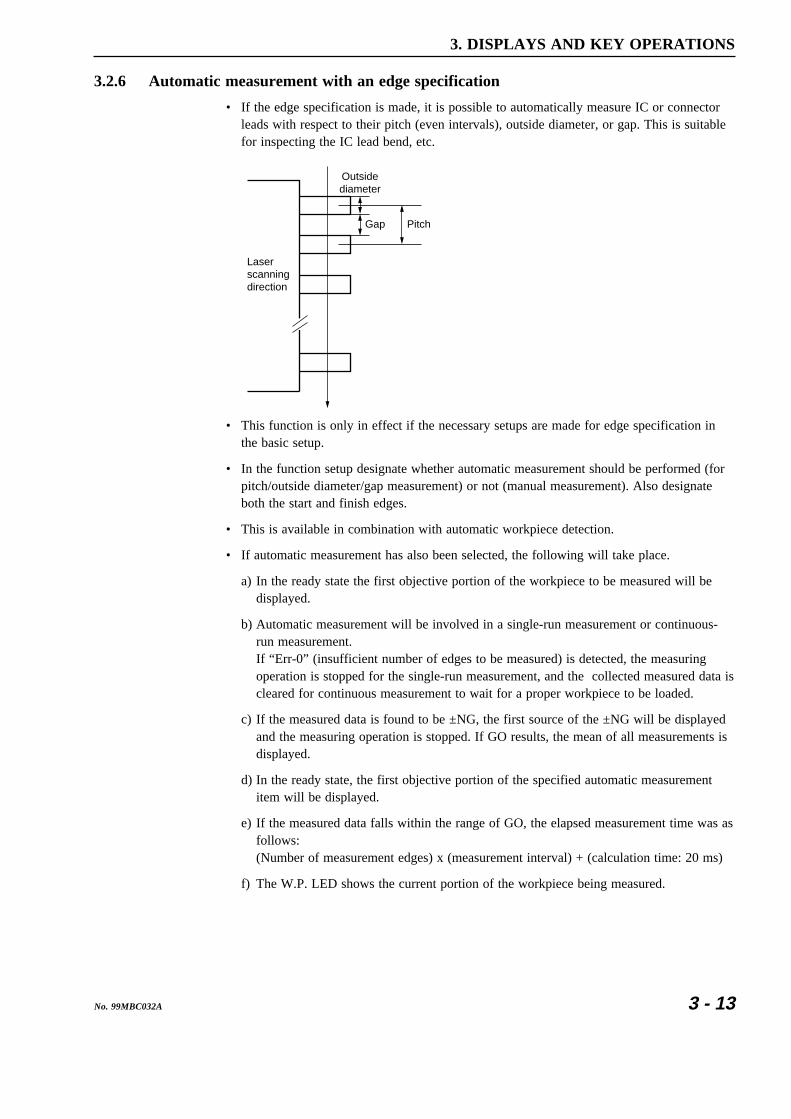
3.2.6 Automatic measurement with an edge specification
• If the edge specification is made, it is possible to automatically measure IC or connectorleads with respect to their pitch (even intervals), outside diameter, or gap. This is suitablefor inspecting the IC lead bend, etc.
Pitch
Laserscanningdirection
Gap
Outsidediameter
• This function is only in effect if the necessary setups are made for edge specification inthe basic setup.
• In the function setup designate whether automatic measurement should be performed (forpitch/outside diameter/gap measurement) or not (manual measurement). Also designateboth the start and finish edges.
• This is available in combination with automatic workpiece detection.
• If automatic measurement has also been selected, the following will take place.
a) In the ready state the first objective portion of the workpiece to be measured will bedisplayed.
b) Automatic measurement will be involved in a single-run measurement or continuous-run measurement.If “Err-0” (insufficient number of edges to be measured) is detected, the measuringoperation is stopped for the single-run measurement, and the collected measured data iscleared for continuous measurement to wait for a proper workpiece to be loaded.
c) If the measured data is found to be ±NG, the first source of the ±NG will be displayedand the measuring operation is stopped. If GO results, the mean of all measurements isdisplayed.
d) In the ready state, the first objective portion of the specified automatic measurementitem will be displayed.
e) If the measured data falls within the range of GO, the elapsed measurement time was asfollows:(Number of measurement edges) x (measurement interval) + (calculation time: 20 ms)
f) The W.P. LED shows the current portion of the workpiece being measured.

3 - 14 No. 99MBC032A
3.2.7 GO/NG judgment
• All the measured data are subject to GO/NG judgment.To enable, set the GO/NG judgment criteria in advance.
• The following settings can be made in the basic setup.
a) The method of tolerance judgment can be selected from (Lower limit value and upperlimit value), multi-limit selection (7 limits) and (Target value and tolerance values:upper tolerance value and lower tolerance value).The judgment result with the multi-limit selection will be outputted via RS-232Cinterface.
b) Simultaneous measurement can be specified. The judgment result will be outputted viaRS-232C interface.
c) For (Target value and tolerance values), the user is permitted to select whether thetarget value is to be copied to the reference value. If it is, the setup guidance for thereference value will not appear.
d) Even in the ready state it is possible to select whether tolerance judgment is performed.However, this data is not available for statistical processing.
e) Abnormal data elimination, tolerance judgment, group judgment, and analog outputcan be performed in a single-run measurement, zero-run measurement, sample mea-surement, and continuous-run measurement. The judgment result will be indicated bythe -NG (red LED), GO (green LED), and +NG (red LED) indicators and outputted tothe RS-232C (including printer) interface.
f) The following tables show the relationship between the measured data and tolerancejudgment method
1) (Lower and upper limit values)
tnemgdujGN/OG )teseraseulavtimilreppudnarewolehthtobfidegduj(tnemerusaeM
GN- eulavtimilrewoL<tnemerusaeM
OG eulavtimilrewoL ≤ eulavtimilreppU<tnemerusaeM
GN+ tnemerusaeM ≥ eulavtimilreppU
2) (Target value and tolerance values)
tnemgdujGN/OGreppudnaeulavecnarelotrewol,eulavtegratehtfidegduj(tnemerusaeM
)teseraeulavecnarelot
GN- )timilecnarelotrewol+eulavtegraT(<tnemerusaeM
OG)eulavecnarelotrewol+eulavtegraT( ≤ reppu+eulavtegraT(<tnemerusaeM
)eulavecnarelot
GN+ tnemerusaeM ≥ )eulavecnarelotreppu+eulavtegraT(

3 - 15No. 99MBC032A
3. DISPLAYS AND KEY OPERATIONS
3) If all limits from L1 to L6 are set for multi-limit selection
tuptuonoitcelestimil-itluM tnemgdujGN/OG .tesera6Lot1LmorftnemerusaeM
1L GN- 1L<tnemerusaeM
2L OG 1L ≤ 2L<tnemerusaeM
3L OG 2L ≤ 3L<tnemerusaeM
4L OG 3L ≤ 4L<tnemerusaeM
5L OG 4L ≤ 5L<tnemerusaeM
6L OG 5L ≤ 6L<tnemerusaeM
7L GN+ 6L ≤ tnemerusaeM
4) If only L1 and L2 are set for multi-limit selection
tuptuonoitcelestimil-itluM tnemgdujGN/OG.tesera2Ldna1LylnOtnemerusaeM
enoylnofidemrofrepebtonlliwtnemgduJ().tessiegats
1L GN- 1L<tnemerusaeM
2L OG 1L ≤ 2L<tnemerusaeM
7L~3L GN+ 2L ≤ tnemerusaeM

3 - 16 No. 99MBC032A
3.2.8 Abnormal data elimination
• The abnormal data elimination function eliminates measurements that are very differentfrom those specified for the machined workpiece, from the measurement data (neither themeasurement is displayed nor is data output performed).If, for example, the grindstone of a centerless grinder is controlled based on the measureddata from the LSM, it is possible that a large measurement error may be created due to thecoolant used with the workpiece.As shown in the figure below where foreign matter (with a height of h) adheres to withinthe averaging region L of the workpiece (with a diameter of D). An abnormal outsidediameter results in the region of l and the displayed measurement will be (D + lh / L). Asthe result the grinder is subject to improper control that involves some error.
h
D Workpiece
l
L
Workpiece feed direction
Because the use of this function can eliminate abnormal measurement data generated dueto the adhered foreign matter, the grindstone can be controlled and fed properly.
• Judgment of valid data or abnormal data will be performed at each measurement interval.Valid data includes those satisfy the following relation: Lower abnormal limit (Measure-ment) < Upper abnormal limit. All other data will be discarded as abnormal data.
• The following table shows the relationship between measurements and upper and lowerabnormal limits.
etanimiletonoD/etanimilErewoldnareppuehthtobfidegduJ(tnemerusaeM
).teserastimillamronba
etanimilE timillamronbarewoL<tnemerusaeM
etanimiletonoD)tnemerusaemasadetpecca(
timillamronbarewoL ≤ reppU<tnemerusaeMtimillamronba
etanimilE tnemerusaeM ≥ timillamronbareppU
• In the basic setup select whether this abnormal data elimination function should be used. Ifit is the setting of (lower abnormal limit and upper abnormal limit) should be performedbefore actual tolerance judgment.
• Abnormal data elimination function effects in single-run and continuous-run measure-ments.
• If “Err-0” (specified workpiece not present) is displayed in the sample measurement, thevalid data collected will be discarded.

3 - 17No. 99MBC032A
3. DISPLAYS AND KEY OPERATIONS
3.2.9 Offset/Zero-set
This function is used to measure the difference between the workpiece and the reference gageor to measure the workpiece that is larger than the measuring range of the LSM.
a) Offset• In this system the operation of setting the reference gage dimension is called the
offset operation.• This function is applied to measure the absolute dimension of a workpiece.
b) Zero-set• Setting the reference gage dimension to “0.0” for the purpose of comparing it with a
workpiece dimension is called the zero-set.• This function is applied to measure a deviation from the reference gage dimension.
c) DirectionDepending on the objective portion of measurement of a workpiece, the positivedirection (set as “0”) or negative direction (set as “1”) must be set.If, for example, the shaded portion of D in the following diagram is measured, thedirection must be set as positive (0). If the highlighted portion (gap) of W is to bemeasured for determining the workpiece dimension L, the direction must be specifiedas negative (1).
D
W
L
Reference piece
Reference plane
Workpiece
Workpiece
Set as positive (0) Set as negative (1)
• Offset operation takes about 1 second to determine the compensation value by measuringthe reference gage.
• Offset value will be ineffective if the segment or edge number is changed (Offset value isunique to each segment or edge).
3.2.10 Mastering
• If the objective workpieces are high-precision gages that are machined successively, theabove described offset/zero-set values may need to be fine-adjusted to the master. Thisfine-adjustment is called mastering.After mastering, the total compensation value will be:(Offset value/zero-set value) + (±Mastering value)
Setting a positive (+) mastering value allows the measurement of a workpiece OD to begreater than the raw measurement, and setting a negative (-) mastering value allows themeasurement of a workpiece OD to be smaller than the raw measurement.
• Because no measurement is required for this mastering, the reference gauge is not requiredeither.
• Mastering will be cancelled if subjected to offset/zeroset.
• Set the reference gage dimension with the offset function and perform mastering.
3 - 18 No. 99MBC032A
3.2.11 Reference value
• In the basic setup the following conditions can be set.a) Whether the target value of GO/NG judgment is being copied to the reference value. If
this is selected, the setup guidance for the reference value will not be displayed.b) It is also possible to set so that tolerance judgment can take place in the ready state.
• If the reference value is being set the deviation value (Measured data-reference value) willbe output for the RS-232C interface and the printer if single-run measurement or continu-ous-run measurement is performed.
3.2.12 Data output conditions
• In single-run measurement or continuous-run measurement, measured data can be output-ted for each measurement if ±NG occurs, or at given intervals to the RS-232C interface,printer, or Mitutoyo Digimatic Output Unit interface.
C.RUNRUN
C.RUNRUN
C.RUNRUN
Data output condition PrinterRS-232CDCU
Remark
The periodical output timer can be set
0
1
2
7
— —
—
—
—
—
8
9
6
The periodical output timer can be set5
4
The periodical output timer can be set3
: Outputted for each measurement if or key, etc., is pressed. : Press the or key to trigger the measurement. The measured data will be outputted if it falls on GO. : Press the or key to trigger the measurement. The measured data will be outputted if it falls on ±NG. : No output will be made.
—
—
—

3 - 19No. 99MBC032A
3. DISPLAYS AND KEY OPERATIONS
3.2.13 Automatic workpiece detection <OD detection method, Position detection method>• Automatic workpiece detection is performed for continuous-run measurement, where
measurement starts with no specified workpiece present (Err-0), then proceeds to auto-matic detection of the workpiece, followed by measurement repeated number of times. Nospecified workpiece present (Err-5) also refers to the workpiece outside the upper andlower detection limits.
• Whether automatic workpiece detection is performed is specified in the basic setup mode.If automatic workpiece detection is specified, the number of scanning times for detectionmust be specified from among 1 and 16. Select 16 times if detecting precision workpieces.If automatic workpiece detection is not specified, no further setting is necessary.
• Automatic workpiece detection setup includes the number of measurement times, invalida-tion period, upper and lower detection limits. Both the upper and lower detection limitsmay not always need to be specified, however, they should be set for safety.
• To exclude the measured data of such as chamfered portion of the workpiece, invalidationperiod can be set within the range from 0.001 sec to 9.999 sec.
No workpiecedetected
Start ofmeasurement
Detection ofworkpiece
Invalidationelapses
Measured the specifiednumber to times
1) OD detection method• This is used to automatically detect a workpiece that enters the laser scanning plane
perpendicularly.• For actual detection of a workpiece the displayed measurement (after calibration and
offset) is used.• One session of automatic detection consists of no workpiece being detected, detec-
tion of a workpiece with a dimension that is within the detection range (between theupper and lower detection limits), an invalidation period required to exclude invaliddimensions (of chamfered portions, etc.) from the measurement, and effectivemeasurement for the specified number of times. The final measurement result will belatched (held) on the display. Once entering the effective measurement the upper andlower detection limits will no longer be checked.
• The speed of workpiece detection (i.e. the number of scans) can be specified aseither 1 or 16 in the basic setup.
• Use 16 times in the following cases:* If connecting bars are used between workpieces for feeding convenience and for
setting appropriate intervals between workpieces, and, if the difference in theoutside diameter between the workpiece and the bar is insufficient.
* If the feed rate is low.• The following diagram is an example where a workpiece with a chamfered outside
diameter of D mm and a length of L mm moves at a velocity of V mm/s.
D a
Lc g Scanning beam
Workpiece flow V mm/s

3 - 20 No. 99MBC032A
Setting example:• Lower detection limit: L < (a +D) / 2• Upper detection limit: H > Upper limit of the measuring range or 1.1 D
(This setting may be omitted.)• Invalidation period : T > (c / V) ms• Number of measurements: N < (L - 2c) x 0.8 (safety factor) / measurement interval
2) Position detection method• This is used to automatically detect a workpiece that enters the measuring region in
the laser scanning plane in the same direction of the scan.• Workpiece detection is performed with one scan, and 16 scans can not be specified
(If specified in the basic setup, the specification will be ignored).• One session of automatic detection consists of the detection of no workpiece,
detection of a workpiece edge with a dimension that falls within the detection range(between the upper and lower detection limits), an invalidation period required toexclude invalid dimensions from the measurement, and effective measurement for thespecified number of times. Once the effective measurement has been entered, theupper and lower detection limits will no longer be checked.
• In the following diagram, workpiece positions (a) and (b) result in no workpiecebeing present, and in (c) it is judged that a workpiece is present.
(a)
(b)
(c)
V m
m/S
Detected edge
Mea
surin
g re
gion
Lase
r sc
anni
ng d
irect
ion
Lase
r sc
anni
ng r
ange
H
CL
C : Detection rangeH : Upper detection limitL : Lower detection limit
Setting example:Assuming the workpiece diameter as D (mm) and the moving speed as V (mm/s):
• Lower detection limit: L > (Laser scanning range - measuring region) / 2• Upper detection limit: H < (Laser scanning range + measuring region ) / 2 - D (This
setting may be omitted.)• Invalidation period : Generally set to 0 ms.• Number of measurements: N = 1
NOTE • Allow a sufficient margin for the lower detection limit, upper detection limit, invali-dation period, and number of measuring times when setting them. If this surplus isnot sufficient, the measurement may not be achieved.
• If using the sample measurement, specify the number of measuring times to 1.• The automatic workpiece detection functions in the continuous-run measurement.

3 - 21No. 99MBC032A
3. DISPLAYS AND KEY OPERATIONS
3.2.14 Group judgment
• While the tolerance judgment is applied to each measurement from a workpiece, this groupjudgment is applied to a group of the specified number of workpieces.
Judgment to Group 1 Judgment to Group 2 Judgment to Group 3
Individualjudgment
1
Individualjudgment
2
Individualjudgment
3
Individualjudgment
4
Individualjudgment
5
Individualjudgment
6
Individualjudgment
7
Individualjudgment
8
• In the basic setup select whether group judgment is to be performed. If it is, then set thegroup size (the number of workpieces included in a group), calculation items (mean,maximum value, minimum value, and range), and group lower limit and upper limit. If“Not performing group judgment” is selected, the setup guidance for it will not be dis-played.
• The group judgment will be in effect in a single-run measurement or continuous-runmeasurement.a) For the result display and GO/NG judgment indication each individual measurement
and judgment result will be used.b) RS-232C output
In the basic setup it is possible to set whether the group judgment result data is output-ted for the RS-232C interface. If it is, the output contents from the group judgment willbe as follows:
P0, ( GO) 12.34567 ... Individual dataP0, ( GO) 12.34560 ... Individual dataP0, (+NG) 12.34600 ... Individual dataGP0, ( GO) 12.34575 ... Group judgment result data
• Each individual piece of measurement data can be the objective of statistical processing,however, group measurement data will be excluded from statistical processing.
• Even if “Err-0” (specified workpiece not present) occurs, the obtained data will not becleared. To abort the measurement, press the C key (or input the “CL” commandvia the RS-232C interface).

3 - 22 No. 99MBC032A
3.2.15 Recording the amount of light
• The gap measurement may be unstable if not enough laser beam passes through the gaps.In the case shown in diagram (a) below, an adequate amount of light can be obtained asthe laser passes through gap (g) above the workpiece, even if the gap (t) is small. How-ever, in diagram (b) where gap (t) is small, measurement will be affected. In this case,therefore, it is necessary to have the system record the full amount of light when there isno obstruction (workpiece or fixture) in the optical path.
Workpiece
Workpiecet
g: Gap for the
reference beam
t
Gap
Gap
(a) Light amount can be detected normally = Auto-detecting
(b) Recording the amount of light is required
Laser beam passes through this gap.
Light amount cannot be detected (insufficient duration)
Photo-electric signal
Light amount can be detected
Peak of the photo-electricsignal
• Normally the amount of incident light is continuously checked so that the countingoperation can follow the change in the amount of incident light. The minimum size of gap“g” or “t” is 2 mm. Have the system record the light amount following 4.4, “How to read-in the amount of light”. It is also necessary to carry out this operation twice or three timeseach year since the light amount of the system may vary.

3 - 23No. 99MBC032A
3. DISPLAYS AND KEY OPERATIONS
3.3 Outline of the Display ContentsDisplays of this system are effected by the display unit and guidance LEDs.
3.3.1 Display unit
The name of each part of the display unit and the LEDs are given below:
PROG
BUSYRUN+NGGO-NG
LOCK DUALOFFSETCAL S.E
Data display unit (fluorescent display tube)
Upper display section
Lower display sectionMeasurement state guidance
BUSY LEDRUN LEDGO/NG judgment LEDsLD oscillation LEDW.P. (Work Position) LED
LASER EMISSION
3.3.2 Data display unit
1) Numeric and character display
• Single measurement: Turns off.• Simultaneous measurement:
Displays a background program number.• Displays a settting item in the single measurement.• Single measurement: Displays a setup value.• Simultaneous measurement:
Displays the measured data of a background program.• Displays the unit of measurement.
• Displays the measureddata of a foreground program.
• Displays a foreground program number.
2) Operation state guidance• LOCK: Turns on in the key lock state, which is initiated by pressing both the SHIFT
and LOCK / UNIT keys. If these keys are input the key lock state will becanceled.
• CAL: Turns on if the calibration (HI CAL) is specified.• OFFSET: Turns on if the offset function is active.• S.E: Turns on if statistical processing is activated.• DUAL: Turns on if simultaneous measurement is specified.

3 - 24 No. 99MBC032A
3) Display LED• W.P. (Work Position) LED
LED segments corresponding to a region shaded by the workpiece, which blocks thelaser beam, will turn off. This is used to check if the workpiece is located in the centerof the measuring region.
• LD oscillation LEDLASER EMISSION : Indicates that the laser in the Measuring Unit is oscillating.
• GO/NG judgment LED1. -NG : Turns on if the measured data is -NG.2. GO : Turns on if the measured data is GO.3. +NG : Turns on if the measured data is +NG.
• RUN LEDTurns on if a single-run measurement or continuous-run measurement is performed.
• BUSY LEDTurns on each time the measured data is updated.
IMPORTANT Laser safetyFor safety, the laser will not turn on until 5 seconds after the power is turned on. Ifthe power is unintentionally turned on, turn off the power within 5 seconds to securethe laser.

3 - 25No. 99MBC032A
3. DISPLAYS AND KEY OPERATIONS
3.4 Outline of Key OperationsOn this system operate the keys as follows.
PROG• The STAT / S.E key, for example, has two functions asindicated on the upper and lower portions of the keytop. The function on the upper portion can be activatedby simply pressing the key, and the one on the lowerportion can be activated by pressing the key whileholding down the SHIFT key. If the SHIFT key ispressed, the currently displayed program number flashesfor about 10 seconds until another key is pressed.During this period one of the functions in the upperportions of the keys can be selected. Press the STAT /
S.E key while the program number is flashing.• To enter the reference gage values, such as HIGH CAL, LOW CAL and offset, or other
setup values such as reference values and GO/NG judgment criteria, etc., the numeric keys( 0 to 9 , . , +/- ) and arrow keys ( , , and ) can beused.
a) If a setup value entry is started with a numeric key and an arrow key is pressed halfway,an operation error will result. The following example shows a case of an offset value.
PROG1. Enter the setup mode of the offset function.The least significant digit of the existing offset valueis flashing.
PROG2. Change the value to 12.00 mm.Press the 1 key.
PROG3. If an arrow key is pressed at this point, an operationerror occurs, however the display does not change.
PROG4. To enable the entry of an arrow key, press the C
key to cancel the setup value.Now the arrow keys are operable.

3 - 26 No. 99MBC032A
b) If a measurement is read as the setup data by pressing the READ key or if the entry of asetup value is started with an arrow key and a numeric key is pressed halfway an operationerror will result. See the example above.
PROG1. Enter the setup mode of the offset function.The least significant digit of the existing offset valueflashes.
PROG2. Enter the key.
PROG3. If a numeric key is pressed at this point, an operationerror occurs, however the display does not change.
PROG4. To enable the entry of a numeric key, press the
C key to cancel the setup value.Now the numeric keys are operable.

3 - 27No. 99MBC032A
3. DISPLAYS AND KEY OPERATIONS
3.4.1 Description of key functions
90
•
+/-
C
SHIFTSTATS.E
SHIFT
SHIFT
READSHIFT
RUN
S.PRPRINT
S.PRPRINT
C.RUN
RUN
C
Key name • In the ready state• In the display-latched state
• At single-run measurement• At continuous-run measurement
• At setup• Combined use with power-on• operation
• Operation error
• Operation error
• Shift key• To enter the function indicated in• the upper portion of a double-• function key, such as the
key, hold down the
• before pressing the key.• A foreground program number will• flash for about 10 seconds.
• Cancels the error that occurred when the power was turned on.• Cancels the latched state and• returns to the ready state.
• Changes the program number
• Operation error
• Operation error
• Operation error • Entry of +
• (to set the light amount detecting• function) is valid when the function• setup item number flashes in the• function setup mode.
• Performs single-run measurement• (even in the display-latched state).
• Results in a single-run• measurement error.• Quits the measuring operation for• continuous-run measurement.
• Operation error
• Starts continuous-run measurement• (even in the display-latched state).
• Quits the measuring operation for• continuous-run measurement• (same as ).
• Operation error
• Prints out the previous• measurement data.• Prints out the data currently• displayed in the display-latched• state.
• Results in a single-run measurement error.• Prints out the previous• measurement data in• continuous-run measurement.
• Operation error
• If the printer is active, prints out all• the statistical processing data and• clears the statistical memory.• If the printer is not active, results in• an operation error.
• Operation error • Operation error
• Aborts the measurement and• returns to the ready state.
• Operation error
• Enters a decimal point.
• Inverts the sign of the setup value.
• Cancels the setup value or resets• it to initial value.• Cancels the error state.
• + power-on will enter the
• initialization mode of the Display• Unit.
• Enters the setup data.

3 - 28 No. 99MBC032A
SET
ENT
LIMIT SET
MASTEROFFSET
SET
SET
ENT
ENT
REF
SET
LIMIT
MASTEROFFSET
MASTEROFFSET
SHIFT
REF
ENT
Key name • In the ready state• In the display-latched state
• At single-run measurement• At continuous-run measurement
• At setup• Combined use with power-on• operation
• Directly enters the setup mode for• GO/NG judgment.
• Performs zero-setting (in the• positive direction) if an offset value• is not set. • If an offset value is set, executes• the offset function with the offset• value being set.• Update of the setup data for the• offset function must be performed• in the function setup mode.
• Directly enters the setup operation• for the reference value.• If "Copying the target value to the• reference value" is specified in the• basic setup, the setup guidance will• not be displayed.
• Directly enters the setup for• mastering.• If no offset value is set, an error• results.
• Enters the function setup mode.
• Operation error
• Operation error
• Operation error • Press to complete the setup
• operation and return to the ready• state.
• Press or to abort the
• setup operation and return to the• ready state.
• Operation error • Operation error • Accepts the setup data that is• pressed.
• Operation error
• Operation error
• Press to complete the setup
• operation and return to the ready• state.
• Press or to abort the
• setup operation and return to the• ready state.
• Operation error
• Press to complete the setup
• operation and return to the ready• state.
• Press or
• to abort the setup operation and• return to the ready state.
• Exits from the function setup mode• and returns to the ready state.• Enters the state that is entered just• after the power is turned on, if in• the basic setup mode.
• + power-on is used to enter
• the basic setup mode.

3 - 29No. 99MBC032A
3. DISPLAYS AND KEY OPERATIONS
STATS.E
SET
SET
ENT
ENT
A.CLM.CL
SET
SET
ENT
ENT
A.CLM.CL
LOCKUNIT
STATS.E
STATS.E
SHIFT
A.CLM.CL
A.CLM.CL
SHIFT
LOCKUNIT
SHIFTLOCKUNIT
Key name • In the ready state• In the display-latched state
• At single-run measurement• At continuous-run measurement
• At setup• Combined use with power-on• operation
• Enters the statistic display mode• and displays N in the statistical• memory.
• Each time the key is
• pressed S.D, MAX, MIN, AVG,• R, and N are sequentially displayed.
• Press or to
• restore the ready state.
• Enters the clear mode of the• statistical memory for the specified• program number.
• Press to execute clear, and
• pressing or to abort the
• clearing operation and return to the ready state.
• Enters the unit change mode.
• Press to execute a change of
• units, and press or
• to abort the unit change operation• and returns to the ready state.
• Enters the clear mode of the• statistical memory for all program• numbers.
• Press to execute clear, and
• press or to abort the
• clearing operation and return to the• ready state.
• Enables/disables statistical• processing.• If statistical processing is active,• measurement state guidance ( ) • for statistical processing turns on.
• Operation error
• Operation error
• Operation error • Operation error
• Enters the key lock mode, turns on• the measurement state guidance• ( ) for the key lock function, then• prohibits subsequent key inputs.• If these keys are pressed again in the key lock state, it will be canceled.
• Operation error • Operation error
• Operation error
• Operation error
• Operation error
• Operation error
• Operation error
• Operation error

3 - 30 No. 99MBC032A
H.CAL SET
SET
ENT
ENT
L.CAL
READ SET
SET
READ
READ
H.CAL
L.CAL
SHIFT
Key name • In the ready state• In the display-latched state
• At single-run measurement• At continuous-run measurement
• At setup• Combined use with power-on• operation
• Enters the LOW CAL setup mode.
• Operation error
• This is used to enter the setup mode• for the setup item that is being• displayed in the upper section of the• display unit.
• Enters the detection mode of the• measurement position• (focal position).
• Press or to restore the
• ready state.
• Enters the HIGH CAL setup mode.
• Operation error
• Operation error
• Operation error • Move left key
• Operation error • Operation error • Move right key
• Operation error • Operation error • Up key to increment the setup value.
• Operation error • Operation error • Down key to decrement the setup• value.
• Operation error
• Operation error
• (Input of gage diameter) +
• executes LOW CAL.
• Press or in the
• LOW CAL setup mode to abort the• setup operation and return to the• ready state.
• Reads the measurement of the• reference gage as the setup value.• The read value can be modified with• the , , ,
• and keys.
• If this entry is made when the• function setup item number is• flashing in the function setup mode,• which was accessed by the
key, the setup operation for
• the light amount detection is entered.
• (Input of gage diameter) +
• executes HI CAL and illuminates• the measurement state guidance ( )• for CAL.
• Press or in the HI CAL
• setup mode to abort the setup• operation and return to the ready• state.

3 - 31No. 99MBC032A
3. DISPLAYS AND KEY OPERATIONS
3.4.2 Example key operations
As an example operation this section uses an update of the tolerance limits which aredisplayed in the upper display section while in the ready state. Suppose that the new lowertolerance limit is “12.34500” and the upper tolerance limit is “12.34600” and that the currentvalues are “12.00000” and “12.00100”.
In the example below, we start with canceling existing upper and lower tolerance limits sincethe lower tolerance limit to be set is smaller than the existing upper tolerance limit. If this isthe case, setting the lower tolerance limit first causes an error (ERR-5).
PROGStep 1: In the ready state press the key to makethe setup item being displayed flash in the upperdisplay section.
Each time the key is pressed, while the setup item is flashing, the setup itemwill change sequentially: Segment → Measurement interval → Offset
→ Lower limit value → Upper limit value → Reference value→ Offset → Mastering →
If the key is pressed, the setup item will change in the reverse order.As the displayed setup items vary with the results of the basic setup, refer to Section5.1.1, “Setup in the measurement mode”
PROGStep 2: If the upper limit value is going to be canceled,make the guidance flash.
PROGStep 3: Press either the ENT or key to make theleast significant digit of the setup data flash.
PROGStep 4: To cancel the upper limit value press the C
key to set the setup data to “0”.
PROGStep 5: If the ENT key is pressed, the upper limit valueis canceled and system operation returns to theready state.
PROGStep 6: After making the guidance flash by pressingthe key, press the and ENT keys toenter the setup mode for the lower limit value.
PROGStep 7: Press the C key to set the display of the lowerlimit value to “0” (can be omitted), then enter anew lower limit value of “12.34500”.

3 - 32 No. 99MBC032A
PROG1
PROG2
PROG.
PROG3
PROG54
↓
1) Each time the numeric key is pressedthe corresponding digit will beplaced in the position of the leastsignificant digit, as shown in thefigure on the right. In this exampleinsignificant zeros ( 0 0 ) arenot entered, they will be automati-cally added to fill the remaining digitplaces when the ENT key ispressed.
PROG
ENT
2) Press the ENT key to save the setupdata of the lower limit value, andreturn to the ready state.If “Inserting a comma (,) after thethousandth digit” is specified in thebasic setup, it will be automaticallyinserted when the ENT key ispressed.
PROGStep 8: As in steps 6 and 7, enter a new upper limit value.
PROGStep 9: If the ENT key is pressed, the setup data of theupper limit value is saved in memory, thenoperation returns to the ready state.
PROGStep 10:Here, for practice, intentionally enter the incorrectupper limit value of “12.34800” then correct it.
PROGStep 11:Enter the setup mode for the upper limit valueagain.
PROG1) Press the key twice to make the thirddigit flash.
PROG2) Press the key twice to change the thirddigit to “6”.
PROG3) Press the ENT key to save the setup data. Theoperation will be automatically return to theready state.

3 - 33No. 99MBC032A
3. DISPLAYS AND KEY OPERATIONS
The following describes how to use the arrow keys using step 7 as an example.
PROG1) Now, the setup data of “0” is displayed as aresult of having pressed the C key.
PROG2) If the key is pressed, the digit places areautomatically filled with zeros to reflect the setresolution, with the appropriate number ofcommas inserted after the thousandth digit, thenthe highlighted digit moves one position to theleft.
PROGIf the key is pressed, the digit places areautomatically filled with zeros to reflect the setresolution, with the appropriate number ofcommas inserted after the thousandth digit, thenthe least significant digit increases by one.
PROGIf the key is pressed, the digit places areautomatically filled with zeros to reflect the setresolution, with the appropriate number ofcommas inserted after the thousandth digit, thenthe least significant digit decreases by one,resulting in a negative value.
PROGIf the key is pressed, the digit places areautomatically filled with zeros to reflect the setresolution, with the appropriate number ofcommas inserted after the thousandth digit, thenthe most significant digit that can be set startsflashing.
Here, for practice, press the key.
PROG3) Press the key twice to move the digit tobe set to the third digit place, then press the
key five times.
PROG4) Press the key to move the digit to be setto the forth digit place, then press the key four times.
PROG5) Press the key to move the target digit tobe set to the fifth digit, then press the key three times.
PROG6) Press the key to move the digit to be setto the sixth digit place, then press the key twice.
PROG7) Press the key to move the target digit tobe set to the seventh digit place, then press the
key.

3 - 34 No. 99MBC032A
PROG8) Press the ENT key to save the setup value inmemory.
IMPORTANT Rounding setup valueSetup value will be rounded off automatically if its least significant digit does notagree with the resolution of the display.Example: In case the resolution is 0.05 μm345,64 > 12.345,60 (least significant digit 4 is rounded off to 0)345,67 > 12.345,65 (least significant digit 7 is rounded off to 5)
TIP About the input of setup data
PROG1. How to enter a signIf “Perform GO/NG judgment by (target value +tolerance)” has been specified in the basic setupand the lower tolerance limit is “-0.015”, input asfollows. In this case a “0” does not need to beplaced in the integer section.
PROG
00 1 5.( )
PROG
+/-
2. READ key: About the read operationGenerally, in the calibration or offset value setup operation a reference gage isused, resulting in a measured data that is very close to the setup value. If this isthe case, first read a measurement as the setup data, then correct the minordifference.
3. To enter a numeric value such as a gage diameter, it is more convenient to usethe numeric keys. To correct a specific digit, it is more convenient to use thearrow keys.
4. To select a setup item such as the resolution in the basic setup, it is better to usethe or key. Use of a numeric key causes an operation error.

4
4- 1No. 99MBC032A
Set up the various functions as required to customize the system for theutmost measurement accuracy.
SETTING UP THEMEASURING CONDITIONS
4.1 Basic Setup• In the basic setup mode select and modify the appropriate functions to meet your measur-
ing purpose. It is not necessary to set up functions which will not be used.• The basic setup should be performed at the beginning of operation.
Modification of the basic setup after calibration or function setup has been made mayresult in the cancellation of the calibration or function setup values.
• Commands via the RS-232C interface can not be accepted in the basic setup mode.

4 - 2 No. 99MBC032A
4.1.1 Outline of the basic setup procedure
B1 mode: a. Setting whether to perform GO/NG judgment result output in the ready state
b. Setting the display message if Err-0 occurs
c. Setting the display message at the start of measurement
d. Setting the averaging method
e. Setting the GO/NG judgment method
f. Setting whether the target value is copied to the reference value
B2 mode: a. Setting the workpiece type (opaque or transparent)
b. Setting the simultaneous measurement
c. Setting the method of specifying segments
B3 mode: a. Setting the abnormal value elimination function
b. Setting the automatic workpiece detection function
c. Setting the number of scans
d. Setting the group judgment
e. Setting the output function to the RS-232C interface
B4 mode: a. Setting the use of the RS-232C port
b. Setting the RS-232C communication baud rate
c. Setting the RS-232C communication data bits
d. Setting the RS-232C communication parity bit
e. Setting the delimiter for communication
f. Setting the RS-232C line control
B5 mode: Reserved
B6 mode: a. Setting the use of DCU
Use the and keys to sw
itch between m
odes.
Basic setup mode (can be entered by pressing the key + Power ON)
Ready state
B0 mode: a. Setting the resolution
b. Setting the number of blanked out (display-off) digits
c. Setting whether a comma (",") is inserted after the thousandth digit
d. Setting the buzzer function
e. Setting the period of the display latch timer
SET

4 - 3No. 99MBC032A
4. SETTING UP THE MEASURING CONDITIONS
4.1.2 Description of each mode
1. Data display unitIf the basic setup mode is entered, the following display appears.The basic setup number “ ” will be flashing in the most significant digit of the upperdisplay section, and the guidance for the setup item, followed by the setup value, will beshown at the right of the setup number.In the lower display section “ ” will be displayed.
PROG
Basic setup number: 1 digitSetup item guidance: 3 to 8 digitsSetup data: 1 to 7 digitsUnit: 2 digits
The set display of "BASIC PROG"
2. Selecting the basic setup number• Each time the key is pressed when the basic setup number is flashing the
function setup number digit changes as follows: → → → → → →→ . To enter the desired setup mode press the ENT key when its setup number is
flashing. If the key is pressed, the setup mode will change in reverse order.• If a key other than , , ENT , or SET is pressed during the selection of a
basic setup number an operation error will result.• When each piece of setup data is accepted with the ENT key in the corresponding
setup mode, the operation will automatically proceed to the next setup item.
3. Setting each setup item• Except for setting up the display latch timer, select the setup item using the or
key and accept the setup specification by pressing the ENT key. When the setupcontent is accepted, the operation will automatically proceed to the next setup item. Insetting the display latch timer, it is better to use the numeric keys rather than the arrowkeys, which, however, are valid.
4. Confirming the setup contents of each setup itemTo confirm the setup specification of each setup item use only the ENT key, which doesnot affect the setup specifications.
5. Terminating the basic setup mode• If the SET key is pressed while the basic setup number is flashing, the setup contents
modified in this session will be saved, and the system will restore the state that isentered just after the power is turned on.
• If the SET key is pressed in the setup mode of each setup item, the operation returnsto the selection of a basic setup number. If the SET key is pressed again at this point ,the setup contents modified in this session will be saved, and the system will restore thestate that is entered just after the power is turned on.
• If the power is turned off halfway the setup operation, setup specifications made willnot be saved. If this is the case, setup should be repeated from the beginning.

4 - 4 No. 99MBC032A
4.1.2.1 Selecting and setting the function in the B0 mode
a. Setting the resolution (Guidance: )Set the resolution of the Measuring Unit. The resolutions that can be set for the MeasuringUnits are given in “Table 4.5.2.1A” and “Table 4.5.2.1B”.
PROGStep 1: Each time the key is pressed the displayedsetup option (number) changes in the followingorder: → → ... → → → . If thedesired option is flashing, press the ENT key. Ifthe resolution setting has been made, the operationautomatically proceeds to the setting for thenumber of blanked out digits.The initial setup option is set to .
1. Resolution using the metric system (Unit: µm) Table 4.5.2.1A
emanledoM 0 1 2 3 4 5 6 7
6059-MSL 50.0 1.0 2.0 5.0 1 2 01 001
2. Resolution using the inch system (Unit: inch) Table 4.5.2.1B
emanledoM 0 1 2 3 4 5 6 7
6059-MSL 200000. 500000. 10000. 20000. 50000. 1000. 5000. 500.
.tinUgnirusaeMhcaefognittestluafedehtwohsserugifdedahsehT:1etoNfosnmulocehtnisnoituloseR:2etoN “ 0” .snacs23morfdeniatboebnachcihwesohtwohs
htiwsnmulocehtnisnoituloseR “ 1” .snacs61morfdeniatboebnachcihwesohtwohstnemerusaemafotigidtnacifingistsaeleht,8ot1neewtebteserasnacsforebmunehtfI:3etoN
.2ro,1,0.oNottessinoitulosererehwtuodeknalbyllacitamotuaeblliw.ycaruccagnirusaemehtecudernetfoyamnoituloseregralootagnittestahtetoN:4etoNforebmunehttes,eesottluciffiddnatcatniylesolcerastigiddeyalpsidehterehW.0b:edomputescisabehtninoitcnuftigidhtdnasuohtehtkramrostigidtuo-knalb
IMPORTANT Changing the resolution will cancel all the clibration values (HIGH CAL and LOWCAL), offset value, mastering, abnormal value eliminating limits, GO/NG judgmentcriteria, reference value, and setup values for the automatic workpiece detection.Therefore, changing of the resolution should be carried out first.
b. Setting the number of blank-out digits (Guidance: )Here, set the number of blank-out digits for measurements to be displayed in the displayunit. This blank out does not apply to the output to RS-232C interface, printer, Digimaticoutput unit, and the display of setup value.
: No blank out (all digits are displayed) → : The least significant digit is blanked out. → : The least significant two digits are blanked out. →
(Default setting is .)
PROGStep 1: Each time the key is pressed the displayedfigure changes in ascending order: → →→ .While the figure to be set is flashing, press the
ENT key.After accepting the specified value, the display proceeds to the setup stage of thenext item.

4 - 5No. 99MBC032A
4. SETTING UP THE MEASURING CONDITIONS
c. Putting a comma after the thousandths digit (Guidance: )Set whether a comma ( ,) is inserted after the thousandths digit.
: Not displayed → : Displayed →
(Default setting is .)
PROGStep 1: Each time the key is pressed the displayedstring toggles between and .Select the setting and press the ENT key.After accepting the specified digit position, thedisplay proceeds to the setting the buzzer function.
d. Setting the buzzer function (Guidance: )Set whether or not to enable (key input sensing sound and key entry error sound) and(±NG judgment sound). Note that the system error sounds (indicating that the printer orDigimatic Output Unit is not connected, or other system failures) are not disabled with thissetting.The types of buzzer sound are as follows:1. Key input sensing sound: very short beep (0.05 sec)2. Key entry error sound: short beep (0.2 sec)3. ±NG judgment sound: long beep (1 sec)4. System error sound: repeated short beeps at intervals of 0.2 seconds
: Sounds a buzzer in all cases.: Enables the key input sensing sound + key entry error sound: Sounds a buzzer when the judgment result is ±NG: Sounds a buzzer only if a system error occurs
(Default setting: )
PROGStep 1: Each time the key is pressed the displayedsetup option changes in the following order:
→ → → . If thedesired option is flashing, press the ENT key.When the setup for the buzzer function is com-pleted, operation automatically proceeds to thesetting of the display latch timer.

4 - 6 No. 99MBC032A
e. Setting the display latch timer (Guidance: )Set the period the measurement result display is to be latched (held) on the display if asingle-run measurement or continuous-run measurement is performed. Specify a valuebetween 0 and 99 seconds. “0” seconds specifies an infinite (latch state not canceled).(Default setting: 10 seconds)
PROG
PROG1
PROG5
PROGENT
Step 1: This is an example of the display latch timer beingset to 15 seconds.Enter 1 and 5 in this order.
Step 2: Press the ENT key to save the setup data inmemory.The operation automatically proceeds to B1:Setting the output function in the ready state.

4 - 7No. 99MBC032A
4. SETTING UP THE MEASURING CONDITIONS
4.1.2.2 Selecting and setting the function in the B1 mode
a. Setting the output function in the ready state (Guidance: )Set whether to perform GO/NG judgment result output in the ready state.
: Neither kind of output is performed in the ready state.: Both kinds of output are performed, even in the ready state.
(Default setting: )
PROGStep 1: Each time the key is pressed the displayedsetup option toggles between and .While the desired setup option is flashing, pressthe ENT key. When the setup for this functionhas been completed, the operation automaticallyproceeds to the display setting in the event of Err-0.
b. Selecting the display message if Err-0 occurs (Guidance: ): Displays “ ”.: Displays “ ” as the least significant digit.
(Default setting: )
PROGStep 1: Each time the key is pressed the displayedsetup option toggles between and .While the desired setup option is flashing, pressthe ENT key. The operation automaticallyproceeds to the selection of the display message atthe start of measurement.
c. Selecting the display message at the start of measurement (Guidance: )Set the message to be displayed at the start of a single-run measurement or continuous-runmeasurement.
: Displays “ ”.: Continuously displays the previous data.
(Default setting: )
PROGStep 1: Each time the key is pressed the displayedsetup option toggles between and
. While the desired setup option isflashing, press the ENT key. The operationautomatically proceeds to the selection of theaveraging method.

4 - 8 No. 99MBC032A
d. Selecting the averaging method (Guidance: )Select one of the following averaging methods: arithmetical average and moving average.
: Arithmetical average: Moving average
(Default setting: )
PROGStep 1: Each time the key is pressed the displayedsetup option toggles between and
. While the desired setup option isflashing, press the ENT key. The operationautomatically proceeds to the selection of the GO/NG judgment method.
e. Setting the GO/NG judgment method (Guidance: )Select one of the following GO/NG judgment methods: (lower limit value and upper limitvalue), (multi-stage selection: 7 stages), and (target value + tolerance).
: GO/NG judgment is performed according to the specified lower limit andupper limit.
: GO/NG judgment is performed according to the multi-limit selection (7stages).
: GO/NG judgment is performed according to the specified target value andtolerance.(Default setting: )
PROGStep 1: Each time the key is pressed the displayedsetup option changes in the following order:
→ → . Whilethe desired setup option is flashing, press the
ENT key. If is selected, operationproceeds to setting whether the target value iscopied to the reference value. If is notselected, operation proceeds to B2: Setting theworkpiece type.
f. Setting whether the target value is copied to the reference value (Guidance: )Set whether the target value is automatically copied to the reference value.
: Target value is not copied to the reference value. : Target value is copied to the reference value.
(Default setting: )
PROGStep 1: Each time key is pressed the displayedsetup option toggles between and
. While the desired setup option isflashing press ENT key. The operation automati-cally proceeds to setting B2: Setting theworkpiece type.

4 - 9No. 99MBC032A
4. SETTING UP THE MEASURING CONDITIONS
4.1.2.3 Selecting and setting the function in the B2 mode
a. Setting the workpiece type (Guidance: )Set whether the workpiece is an opaque object or transparent object.
: Workpiece is an opaque object.: Workpiece is a transparent object.
(Default setting: )
PROGStep 1: Each time the key is pressed the displayedsetup option toggles between and
. While the desired setup option isflashing, press the ENT key. The operationautomatically proceeds to setting whether toperform simultaneous measurement.
TIP If is selected for the workpiece type, the guidance for the selection of thesegment specification method is not displayed. It is omitted (the segment specifica-tion process is entered directly).
b. Setting the simultaneous measurement (Guidance: )Set whether to perform simultaneous measurement.
: Does not perform simultaneous measurement. (performs single measurement): Performs simultaneous measurement.
(Default setting: )
PROGStep 1: Each time the key is pressed the displayedsetup option toggles between and
While the desired setup option isflashing, press the ENT key.
TIP If (simultaneous measurement) is selectedIf simultaneous measurement is selected, the setup guidance for the following willnot be displayed: Selecting the averaging method, segment specification, and settingthe group judgment.
c. Selecting the method of specifying segments (Guidance: )Select the method of specifying the measurement position from segment specification andedge specification.
: Uses segment specification.: Uses edge specification.
(Default setting: )
PROGStep 1: Each time the key is pressed the displayedsetup option toggles between and
. While the desired setup option isflashing, press the ENT key. The operationautomatically enters B3: Setting the abnormalvalue elimination function.
NOTE If any of the following setting is performed, the system automatically proceeds to thestage of segment setup without displaying the guidance for themethod of specifying segments SEG:• a. is selected in Setting the workpiece type.

4 - 10 No. 99MBC032A
4.1.2.4 Selecting and setting the function in the B3 mode
a. Setting the abnormal value elimination function (Guidance: )Set whether to use the abnormal value elimination function.
: Does not use the abnormal value elimination function.: Uses the abnormal value elimination function.
(Default setting: )
PROGStep 1: Each time the key is pressed the displayedsetup option toggles between and .While the desired setup option is flashing, pressthe ENT key. The operation automatically entersthe process for setting the automatic workpiecedetecting function.
b. Setting the automatic workpiece detecting function (Guidance: )Set whether to use the automatic workpiece detecting function.
: Does not use the automatic workpiece detecting function.: Performs automatic workpiece detection with the diameter detection
method.: Performs automatic workpiece detection with the position detection
method.(Default setting: )
PROGStep 1: Each time the key is pressed the displayedsetup option changes in the following order:
→ → . While thedesired setup option is flashing, press the ENT
key. If (the automatic workpiecedetecting function is not used) is selected, theoperation proceeds to setting the group judgment,otherwise it enters the process for setting thenumber of scans.
c. Setting the number of scans (Guidance: )Set the number of scans that are used for the automatic workpiece detecting function.
: Detection from 16 scans: Detection from a single scan
(Default setting: )
PROGStep 1: Each time the key is pressed the displayedsetup option toggles between and . Whilethe desired setup option is flashing, press the
ENT key. The operation automatically enters theprocess for setting the group judgment.
NOTE Even if 16 scans are specified in the position detection method, the actual detectingoperation will be performed with a single scan.

4 - 11No. 99MBC032A
4. SETTING UP THE MEASURING CONDITIONS
d. Setting the group judgment (Guidance: )Set whether to use the group judgment function.
: Does not use the group judgment function.: Uses the group judgment function.
(Default setting: )
PROGStep 1: Each time the key is pressed the displayedsetup option toggles between and .While the desired setup option is flashing, pressthe ENT key. If is selected, the opera-tion proceeds to B4: Setting the use of RS-232Cbaud rate, and if is selected, the operationenters the process for setting the group judgmentresult output function.
e. Setting the group judgement output (Guidance: )Set whether to output the group judgment result to the RS-232C interface.
: Does not output the group judgment result to the RS-232C interface.: Outputs the group judgment result to the RS-232C interface.
(Default setting: )
PROGStep 1: Each time the key is pressed the displayedsetup option toggles between and .While the desired setup option is flashing, pressthe ENT key. The operation automaticallyproceeds to B4: Setting the use of RS-232C port.

4 - 12 No. 99MBC032A
4.1.2.5 Selecting and setting the function in the B4 mode
a. Setting the use of RS-232C port (Guidance: )Set if the RS-232C port is used as the communication port (COM) for a personal com-puter, etc., or as the printer port, or is not used for either.
: Used as the communication port (COM) for a personal computer, etc.: Used as the printer port: Is not used for either purpose
(Default setting: )
PROGStep 1: Each time the key is pressed the displayedsetup option changes in the following order:
→ → . While the desiredsetup option is flashing, press the ENT key. If
is selected, the operation proceeds to B5:Reserved, otherwise it enters the process forsetting the RS-232C communication speed.
b. Setting the RS-232C communication baud rate (Guidance: )Set the RS-232C communication speed (baud rate).
: Uses 9600 bps.: Uses 19200 bps.: Uses 1200 bps.: Uses 2400 bps.: Uses 4800 bps.
(Default setting: )
PROGStep 1: Each time the key is pressed the displayedsetup option changes in the following order:
→ → →→ . While the desired setup option isflashing, press the ENT key. The operationautomatically enters the process for setting theRS-232C data bits.
c. Setting the RS-232C communication data bits (Guidance: )Set the data bits for RS-232C communication.
: Uses 8 bits.: Uses 7 bits.
(Default setting: )
PROGStep 1: Each time the key is pressed the displayedsetup option toggles between and .While the desired setup option is flashing, pressthe ENT key. The operation automatically entersthe process for setting the parity check method forRS-232C communication.

4 - 13No. 99MBC032A
4. SETTING UP THE MEASURING CONDITIONS
d. Setting the RS-232C communication parity bit (Guidance: )Set the parity check method for RS-232C communication.
: Does not use parity check.: Uses odd parity.: Uses even parity.
(Default setting: )
PROGStep 1: Each time the key is pressed the displayedsetup option changes in the following order:
→ → . While thedesired setup option is flashing, press the ENT
key. The operation automatically enters theprocess for setting the delimiter for RS-232Ccommunication .
e. Setting the delimiter for communication (Guidance: )Set the delimiter (termination code of one sentence) for RS-232C communication.
: Uses CR+LF as the delimiter.: Uses CR code as the delimiter.: Uses LF code as the delimiter.
(Default setting: )
PROGStep 1: Each time the key is pressed the displayedsetup option changes in the following order:
→ → . While the desiredsetup option is flashing, press the ENT key. Theoperation automatically enters the process forsetting the control method of the RS-232Ccommunication flow.
f. Setting the RS-232C line control (Guidance: )Set the method of controlling the RS-232C communication flow.
: Does not use a particular control signal (using 3-wire teletype control).: Uses a control signal.
(Default setting: )Note: If the RS-232C interface is set as the printer port, line control will be
achieved by BUSY signals even if this option was set to .
PROGStep 1: Each time the key is pressed the displayedsetup option toggles between and .While the desired setup option is flashing, pressthe ENT key. The operation automaticallyproceeds to B5: Reserved.

4 - 14 No. 99MBC032A
4.1.2.6 B5: Reserved
B5 is not neccessarily to be set, press the ENT key.
B6: The operation automatically proceeds B6: Setting the use of DCU.
4.1.2.7 Selecting and setting the function in the B6 mode
a. Setting the use of DCU (Guidance: )Set whether to use the Mitutoyo Data Processing Unit interface called DCU (DigimaticOutput Unit).
: Does not use DCU.: Uses DCU.
(Default setting: )
PROGStep 1: Each time the key is pressed the displayedsetup option changes in the following order:
→ . While the desired setupoption is flashing, press the ENT key. Theoperation automatically returns to B0: Setting theresolution.

4 - 15No. 99MBC032A
4. SETTING UP THE MEASURING CONDITIONS
4.2 CalibrationThe LSM system can be calibrated quite easily and with high accuracy.
4.2.1 Calibration gages and gage stand
Supported calibration gages and gage stand have the following shapes.
Calibration gages and stand
Thin wire type Straight type Stepped type
Gage stand
4.2.2 Entering the calibration mode
Enter the calibration mode with the following procedure.
< Preparation >(1) Turn on the power and wait at least one hour for the system to thermally stabilize.(2) Prior to use, wipe dust and oil from the gage and gage stand with a cloth soaked in
alcohol or thinner. If calibration has been completed, carefully store them in a dedicatedcase after applying a rust preventive oil to their surfaces.
(3) Specify SEG 2.For information about the method of segment specification, refer to Section 4.5, “SettingUp the Functions”.
PROG
On edge specification, select either manual measurement or automatic measurement withrespect to diameter.
PROG PROG
a) Manual measurement b) Automatic measurement
Set the start edge to 2 and the end edge to 3.
PROG PROG
a) Start edge b) End edge

4 - 16 No. 99MBC032A
(4) Setting the HIGH CAL gauge.HIGH CAL gages vary in shape depending on the LSM model to be calibrated. Set thecalibration gage so that the calibration guide line ( | ) on the side face of the calibrationgage comes vertical, and so that the center of the calibrated section is measured.In diagram (a), the calibrated position is at the center of the ( | | ) mark, and the center ofthe width (indicated by the arrow mark) in diagram (b).
(a) (b)
Step 1: Cancel the previously set calibration values.It is not necessary if this setup operation is made with the previously used calibrationgage. However, if the new gage diameter is much different from that of the previousone, an error (Err-2) may result. If this is the case, cancel the LOW CAL calibrationvalue, then begin with the setting of HIGH CAL value (it does not matter if both theLOW CAL and HIGH CAL values are canceled).
PROG1) Cancel the previous LOW CAL data. Press the
L.CAL key in the ready state to initiate theLOW CAL setup mode.
PROGC
PROG
ENT
2) Press the C and ENT keys tocancel the LOW CAL data. Thisautomatically restores the ready state.
PROGStep 2: Mount the HIGH CAL gage on the stand.Press the H.CAL key in the ready state. Thepreviously set HIGH CAL value is displayed, andthe HIGH CAL setup mode is entered.
Step 3: Enter the approved dimension of the HIGH CALgage.Example.)
PROG20 0 12 4 .

4 - 17No. 99MBC032A
4. SETTING UP THE MEASURING CONDITIONS
PROGStep 4: If the ENT key is pressed to save the HIGH CALsetup value in memory, the operation automati-cally returns to the ready state.
Step 5: Set the LOW CAL gage.As with the HIGH CAL gage, the LOW CALgages vary in shape depending on the LSM modelto be calibrated. Set the LOW CAL gage so thatthe center of the calibration range is properlymeasured.A LOW CAL gage for calibrating dimensions lessthan 2 mm should be set so that it fits with themounting hole of the gage stand.
PROGStep 6: Set up the LOW CAL gage.In the ready state press the L.CAL key. Thepreviously set LOW CAL value is displayed, andthe LOW CAL setup mode is entered.
Step 7: Enter the verified dimension of the LOW CALgage.
PROG50 0 01 .
PROGStep 8: If the ENT key is pressed to save the LOW CALsetup value in memory, the operation automati-cally returns to the ready state.

4 - 18 No. 99MBC032A
IMPORTANT Calibration1. Before performing a calibration, always perform the necessary setup for the
resolution, etc. If this order is reversed, the set calibration value may be canceledand the measurement accuracy is not guaranteed.
2. Canceling the HIGH CAL value will also cancel the LOW CAL, offset, and master-ing values.
3. With only a LOW CAL setup value the compensation calculation does not takeplace. This calculation will start when a HIGH CAL (or HIGH CAL and LOW CAL)value is set.If a HIGH CAL value is set, the CAL guidance ( ) will turn on in the display unit.
4. A calibration gage is important in that it is critical to the accuracy of the MeasuringUnit. Wipe dust and oil from the gage with a cloth soaked in alcohol or thinnerbefore using it.After use, apply a rust preventive oil to its surfaces and store it carefully in adedicated case.
5. To confirm the HIGH CAL or LOW CAL setup value, press either the H.CAL orL.CAL key to enter each setup mode, and press the H.CAL (and SET ) or L.CAL
(and SET ) key to exit to the ready state after the confirmation is over. Do notperform the setup operation in the confirmation process of the setup data.
6. On the user-supplied calibration gages, the dimensional ratio of a High CAL gageto a Low CAL gage should be greater than 1.2. Calibration performed with thecalibration gages with diameters that are too close each other may reduce themeasuring accuracy. The calibration gage should be the one which is made of thesame or similar material as that of the workpiece. If a calibration gage of differentmaterial is used, error may be involved in measurement due to the difference insurface textures or properties.
7. For calibration measurement, no restriction exist for segment specification. If agap or displacement needs to be precisely measured, a thickness gage can beused for calibration. (There will be a slight difference in measured data betweenthose from OD and gap depending on the segment specified for calibration.)

4 - 19No. 99MBC032A
4. SETTING UP THE MEASURING CONDITIONS
4.3 Positioning a Gage or a Workpiece1. Position the calibration gage or workpiece so that it is located at the middle of the mea-
surement position.The shaded section in the following diagram is the measuring region where the ratedmeasuring accuracy of this system is obtained.
2. It is also possible to measure a workpiece or gage located outside the measuring region, aslong as it is within the laser beam scanning range, however, the measurement accuracywill be reduced.
60(2
.36)
98(3
.86)
10(.39)
83(3.27)
Measuring region
4.4 How to read-in the amount of lightFor measurement of the fine gap where the light passing through it can not be sufficientlysecured it is necessary for the system to read-in the amount of light. For more informationrefer to Section 3.2.15, “Recording the amount of light”.
Step 1: Removal of obstructionsRemove any objects (workpiece and fixture) that obstruct the laser path beforereading in the amount of light.
PROGStep 2: Enter the function setup mode from the readystate.
PROGStep 3: Press the SHIFT and READ keys while the functionsetup number is flashing to enter the light amountcheck mode.Each time the key is pressed the setupoption toggles between (automaticdetection) and (reading in the amount oflight).
PROG
PROG
Step 4: Press the ENT key while is flashing.If a sufficient amount of light is detected as aresult of this positive check, the operation auto-matically returns to the ready state. If isdisplayed, it indicates that the amount of light isinsufficient. If this is the case, remove anyobstruction and cancel the error with the C
key, then perform step 4 again.

4 - 20 No. 99MBC032A
4.5 Setting Up the FunctionsMake measurement-related setups based on the conditions set in Section 4.1, “Basic Setup”.
4.5.1 Outline of the function setup mode
SET
SET SETSET( )Ready state
Function No.
F0
Setup contents
Setting the segment
In the basic setup mode, first set whether the workpiece is an opaque or transparent object. If it is an
opaque object, then it is possible to specify the number of segments and edges to be measured.
With the edge specification a multiple-pin workpiece can be measured automatically.
• Segment specification: (Opaque object: 1 to 7, Transparent object: 1 to 3)
• Edge specification: (Manual: / Automatic: / Automatic: / Automatic: )
• Start edge : (Between edge number 1 and 254 )
• Finish edge : (Between edge number 2 and 255)
F1 Setting the measurement interval (measurement time)
In the basic setup mode either of the two setting methods can be selected.
• Arithmetical average: (1 to 2048)
• Moving average: (32 to 2048)
F2 Setting the GO/NG judgment criteria
In the basic setup mode either of the three setting methods can be selected.
In addition, if the abnormal value elimination function will be specified, the limits
(Lower abnormal limit: → Upper abnormal limit: )
for this abnormal value elimination should be set prior to other setup items.
• Lower limit : → Upper limit:
• Multi-limit selection 1: → Multi-limit selection 2: → Multi-limit selection 3: • • • • → Multi-limit selection 6:
Target value : → Lower tolerance limit: → Upper tolerance limit:
F3 Setting the reference value
In the basic setup mode it is possible to copy the setup data of a target value to the reference value.
If this is done the setup guidance for the reference value is not displayed.
• Reference value:
F4 Setting the offset and mastering
Both the offset and mastering can be set.
• Offset: → Direction: (0 , 1) → Mastering:
F5 Setting the data output condition
Data output condition: (0 to 9) : If 1, 3 or 5 is selected → Periodic data output: (0 to 999)
F6 Sample measurement
Number of samples: (0 ~ 999) → Calculation item:
(Mean: / Maximum value: / Minimum value: / Range: )
Note2
Note1
Note1

4 - 21No. 99MBC032A
4. SETTING UP THE MEASURING CONDITIONS
Function No. Setup contents
F7 Setting automatic workpiece detection
In the basic setup mode either detection by dimension or detection by position can be selected.
If “Not performing the automatic workpiece detection” is selected, the setup guidance for the following
option will not be displayed.
Number of measurements: (0 to 999) → Invalidation period: (0 to 9999)
→ Detection lower limit: → Detection upper limit:
• Settings following the circle are factory settings.
• Settings following a dot are ones which have been selected in the basic setup.
• Settings with no marking can be made in only one way.
NOTE 1: Measurement interval and the number of samples are automatically matched in simultaneous measurement.
NOTE 2: The function number may not be displayed depending on the basic setup contents.
F8 Setting the group judgment
In the basic setup mode setups for the group judgment can be made. If “Not performing the group
judgment” is selected, the setup guidance for the following option will not be displayed.
• Group size : (0 ~ 99) → Statistical item:
(Average: / Maximum value: / Minimum value: / Range: )
• Group lower limit value: → Group upper limit value:
Note2
Note2

4 - 22 No. 99MBC032A
4.5.2 Outline of each function setup mode
1. Data display unitIf the basic setup mode is entered, the following is displayed.The function setup number will be flashing in the most significant digit of the upperdisplay section, and the guidance for the setup item, followed by the setup value, will beshown to the right of the setup number.In the lower display section the measurement from the foreground program number will bedisplayed.
Function setup number: 1 digitSetup item guidance: 3 to 8 digitsSetup data: Maximum 10 digitsUnit: 2 digits
Measurement from theforegroundprogram number
PROG
2. Setting each setup item• Use the numeric keys for setting the setup value, such as an offset value, and use the
and keys for selecting the item, such as the statistical item of the samplemeasurement.
• Press the ENT key to accept and save the setup data. After the setup content has beenaccepted, the operation automatically proceeds to the next setup item.
3. Setup values that must meet the large/small relationshipsThe setup values for GO/NG judgment should meet the following relationships: Abnormallower limit < Abnormal upper limit, Lower tolerance limit < Upper tolerance limit, andLower limit value < Upper limit value.If the previously specified setup value needs to be modified to a great extent, it is recom-mended to first enter the new setup value thats meets the existing large/small relationshipor, for safety, cancel the both sides to 0 then set them again.
4. Confirming the setup contents of each setup itemTo confirm the setup contents of each setup item use only the ENT key, which does notaffect the setup contents.
5. Terminating the function setup mode• If the SET key is pressed while the function setup number is flashing, operation
returns to the ready state.• If the SET key is pressed in the setup mode of each setup item, operation returns to
the selection of a function setup number. If the SET key is pressed again at this point,operation returns to the ready state.
• If the power is turned off halfway to the setup operation, on-going setup contents willnot be saved in memory. The contents must be set again.

4 - 23No. 99MBC032A
4. SETTING UP THE MEASURING CONDITIONS
4.5.3 Function setup mode
PROG• If the function setup mode is entered using the SET
key in the ready state, the function setup number will be flashing as shown in the figure at the right.
• Each time the key is pressed when the functionsetup number is flashing, it will change as follows: → → → → → → → → →
. Press the ENT ( ) key while the desiredfunction setup number is flashing to enter the setupmode. If the key is pressed, this order will bereversed.
• If a key other than the , , , ENT and SET keys are pressed during theselection of a function setup number, an operation error will result.
• If each piece of setup data is accepted with the ENT key in the corresponding setupmode, the operation will automatically proceed to the next setup item.
4.5.3.1 F0: Setting the segment
Use this function to set the measurement position (segment). The segment specification andedge specification methods are provided for this purpose. Both can be selected in the basicsetup.
If this setup mode is entered, the previously established data will flash.
7 6 5 4 3 2 1
PROG
Segment
1) Segment specificationPlaces for displaying the segment numbers are fixed asshown in the figure at the right. In this example, set toSEG2.
PROGStep 1: If the segment setup mode is entered, the previ-ously established data will be displayed.
PROG2
Press the 2 key.
PROG
ENT
Step 2: Press the ENT key to save the setup datain memory.Operation automatically proceeds to themeasurement interval setting.
TIP Segment setup example
PROG2 4
1. Set to segments (2 + 4).
PROG1 5
2. Set to segments (1 + 5).

4 - 24 No. 99MBC032A
2) Edge specification
PROGStep 1: If the edge specification mode is entered, thepreviously established manual measurement/automatic measurement item will be displayed.
PROGEach time the key is pressed the setupoption changes in the following order:Manual measurement: → Automaticmeasurement for pitch: → Automaticmeasurement for diameter: → Automaticmeasurement for gap: . If the desired setupoption is displayed, press the ENT key.Operation automatically enters the process of setting the start edge.
PROG
2
Step 2: Set the start edge (between number 1 and254)In this example, set the start edge tonumber 2.If the ENT key is pressed, the operationautomatically enters the process for settingthe finish edge.
PROG
56
Step 3: Set the end edge (between number 2and 255)In this example, set the end edge tonumber 65.If the ENT key is pressed, the operation auto-matically proceeds to F1: Setting the measurementinterval.
TIP 1. If a calibration is performed using the reference gage (placed in SEG2) with theedge specification active, select Manual measurement: or Automaticmeasurement for diameter: , then set the start edge to 2 and end edge to 3.
2. If the checks on the start and end edges, performed at the end of the setupoperation, result in start edge > end edge, exchange the start and end edge data.If the check result shows that both edge numbers are identical, an error (Err-5)results. If this occurs, cancel the setup data and begin the setting with the startedge.
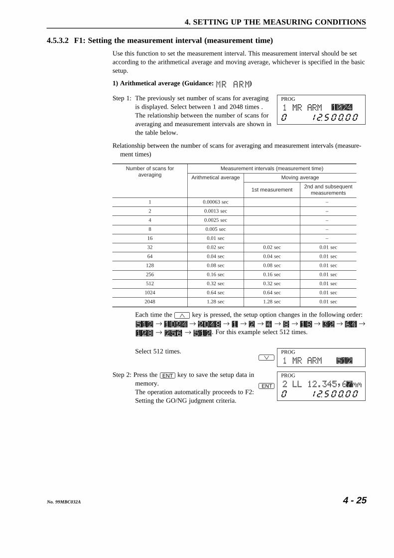
4 - 25No. 99MBC032A
4. SETTING UP THE MEASURING CONDITIONS
4.5.3.2 F1: Setting the measurement interval (measurement time)
Use this function to set the measurement interval. This measurement interval should be setaccording to the arithmetical average and moving average, whichever is specified in the basicsetup.
1) Arithmetical average (Guidance: )
PROGStep 1: The previously set number of scans for averagingis displayed. Select between 1 and 2048 times .The relationship between the number of scans foraveraging and measurement intervals are shown inthe table below.
Relationship between the number of scans for averaging and measurement intervals (measure-ment times)
rofsnacsforebmuNgnigareva
)emittnemerusaem(slavretnitnemerusaeM
egarevalacitemhtirA egarevagnivoM
tnemerusaemts1tneuqesbusdnadn2
stnemerusaem
1 ces36000.0 –
2 ces3100.0 –
4 ces5200.0 –
8 ces500.0 –
61 ces10.0 –
23 ces20.0 ces20.0 ces10.0
46 ces40.0 ces40.0 ces10.0
821 ces80.0 ces80.0 ces10.0
652 ces61.0 ces61.0 ces10.0
215 ces23.0 ces23.0 ces10.0
4201 ces46.0 ces46.0 ces10.0
8402 ces82.1 ces82.1 ces10.0
Each time the key is pressed, the setup option changes in the following order:→ → → → → → → → → →→ → . For this example select 512 times.
PROGSelect 512 times.
PROG
ENT
Step 2: Press the ENT key to save the setup data inmemory.The operation automatically proceeds to F2:Setting the GO/NG judgment criteria.

4 - 26 No. 99MBC032A
2) Moving average (Guidance: )
PROGDifferent in the setup guidance ( ) and thenumber of scans for averaging (between 32 and2048), however, the setup method is same withthe arithmetical average.
NOTE 1. A larger number of scans for averaging will improve the repeatability.If measuring time permits, set the greatest number of scans for averaging pos-sible.
2. If the number of scans for averaging is set to between 1 and 4, the scan signalswill be thinned for the measurement. This results in a measurement interval of0.002 to 0.003 second.

4 - 27No. 99MBC032A
4. SETTING UP THE MEASURING CONDITIONS
4.5.3.3 F2: Setting the GO/NG judgment criteria
Set the GO/NG judgment criteria according to the tolerance judgment method: (Lower limitvalue + Upper limit value), (Multi-stage selection: 7 stages), and (Target value + tolerance),whichever is specified in the basic setup. If “Using the abnormal value elimination function”has been specified, the abnormal limit values should be set prior to setting the GO/NGjudgment criteria.
In this example assume that the machining target value is 12.5 +/- 0.01 mm, and that all theabnormal limits (lower and upper) and GO/NG judgment criteria are canceled (set to 0).
1) Setting the abnormal limit valuesSet as follows: Lower abnormal limit = 12.48 mm, Upper abnormal limit = 12.52 mm.
PROG
. 41 2 8PROG
Step 1: The previously set lower abnormal limit isdisplayed.Enter “12.48”.
PROGStep 2: Press the ENT key.The setup data will be saved in memory andoperation automatically proceeds to the setting forthe upper abnormal limit.
Step 3: Enter “12.52”, which is the setup data for theupper abnormal limit.
. 51 2 2PROG
PROG
Case of (Lower limit value and Upper limit value)
Step 4: Press the ENT key.The setup data will be saved in memoryand operation will automatically proceed tothe GO/NG judgment criteria setting.The method of GO/NG judgment varieswith the contents of the basic setup.
PROGPROG
Case of (Multi-stage selection) Case of (Target value + tolerance)

4 - 28 No. 99MBC032A
2) GO/NG judgment criteria setting (by “Lower limit value and upper limit value”)In this example assume that the lower limit value is 12.49 mm and that the upper limitvalue is 12.51 mm.
PROG
. 41 2 9PROG
Step 1: The previously set lower limit value is displayed.Enter “12.49”.
PROGStep 2: Press the ENT key.The setup data will be saved in memory and theoperation automatically proceeds to the upperlimit value setting.
Step 3: Enter “12.51”, which is the setup data for theupper limit value.
. 51 2 1PROG
PROGStep 4: Press the ENT key.The setup data will be saved in memory and theoperation automatically proceeds to the referencevalue setting.

4 - 29No. 99MBC032A
4. SETTING UP THE MEASURING CONDITIONS
3) Setting the GO/NG judgment criteria (by multi-limit selection)In this example assume the following:L1=12.49mmL2=12.494mmL3=12.498mmL4=12.502mmL5=12.506mmL6=12.51mm
PROG
. 41 2 9PROG
Step 1: The previously entered setup value for L1 isdisplayed.Enter “12.49”.
PROGStep 2: Press the ENT key.The setup data will be saved in memory and theoperation automatically proceeds to the L2 setting.
Step 3: Enter “12.494”, which is the setup data for L2.
4. 41 2 9PROG
PROGStep 4: Press the ENT key.The setup data will be saved in memory and theoperation automatically proceeds to the L3 setting.
Step 5: As with L1 and L2, set L3, L4, and L5.
PROG
. 51 2 1PROG
Step 6: Enter “12.51”, which is the L6 setup value.
PROGStep 7: Press the ENT key.The setup data will be saved in memory and theoperation automatically proceeds to the referencevalue setting.

4 - 30 No. 99MBC032A
4) Setting the GO/NG judgment criteria (with “Target value + tolerance”)In this example assume that the target value is 12.5 mm, lower tolerance is -0.01 mm, andupper tolerance is 0.01 mm.
PROG
. 51 2PROG
Step 1: The previously set target value is displayed.Enter “12.5”.
PROGStep 2: Press the ENT key.The setup data will be saved in memory and theoperation automatically proceeds to the lowertolerance value setting.The target value will be automatically copied onthe reference value if so set in the basic setup.
Step 3: Enter “0.01”, which is the lower tolerance value,and a negative sign.
0 1PROG
0 .( )
+/-PROG
PROGStep 4: Press the ENT key.The setup data will be saved in memory and theoperation automatically proceeds to the uppertolerance value setting.
Step 5: Enter “0.01”, which is the upper tolerance value.
0 1PROG
0 .( )
PROG
When copying the target value to the reference value.
When not copying the target value to the reference value.
PROG
Step 6: Press the ENT key.The setup data will be saved in memory and theoperation automatically proceeds to the referencevalue setting.The displayed guidance for the setup item willvary depending whether “Copying the target valueto the reference value” has been specified in thebasic setup.

4 - 31No. 99MBC032A
4. SETTING UP THE MEASURING CONDITIONS
4.5.3.4 F3: Setting the reference value
Set the reference value here. If “Copying the target value to the reference value” has beenspecified in the basic setup, the setup guidance for the reference value will not be displayed.
In this example assume that the reference value is 12.5 mm.
PROGStep 1: The previously set reference value is displayed.Enter “12.5”.
1PROGIf “1” is entered the currently displayed
setup value changes to “1”, however, it willnot be saved in memory until the ENT
key is pressed.
2PROGEnter “2”.
.PROGEnter a decimal point (“.”).
5PROGEnter “5”.
PROGStep 2: Press the ENT key.
The setup data will be saved in memory and theoperation automatically proceeds to the offsetvalue setting.

4 - 32 No. 99MBC032A
4.5.3.5 F4: Setting the offset value
Set the offset value and/or mastering value here.
In this example assume that the offset value is 12.5 mm, the direction is 0 (positive), and themastering value is 0.0. Assume also that the current offset value is 12.345 mm.
PROG
. 51 2PROG
Step 1: The previously set offset value is displayed.Enter “12.5”.
PROGStep 2: Offset guidance ( ) turns on and the setup datawill be saved in memory and the operationautomatically proceeds to the direction setting.
PROGStep 3: Set the direction to “0”.Since in this example the previous setting is “0”,it is not necessary to enter the same value again.However, if there is a need to change the directionto “1”, enter “1”.
PROGStep 4: Press the ENT key.The setup data will be saved in memory and theoperation automatically proceeds to the masteringvalue setting.
Step 5: Enter “0.0”, which is the mastering value.
. 00PROG
PROGStep 6: Press the ENT key.The setup data will be saved in memory and theoperation automatically enters the data outputcondition setting.

4 - 33No. 99MBC032A
4. SETTING UP THE MEASURING CONDITIONS
IMPORTANT How to use the offset function1. To obtain an offset value, it is necessary to set up the reference gage in place
(the offset value is a compensation value determined from the measurement ofthe reference gage). This offset setup takes about 1 second.
PROG2. If the existing setup value is applied, it is notnecessary to carry out the offset. To force theoffset operation using the same data, move thehighlighted digit place with the key. Thismakes the offset carried out, since the systemjudges the data is changed.For this operation press the MASTER / OFFSET key in theready state. With this single key operation offsetwill be carried out.
3. So that the maximum displayable range is not exceeded during measurement, theoffset value must be set well within the maximum value shown in the table below.If measured data exceed the maximum value, “9999999” will be displayed.
(noituloseR μ )m )mm(eulavmumixaM )E(noituloseR )E(eulavmumixaM
50.0 ± 99999.98/200000.
500000.± 999999.8
5.0/2.0/1.0 ± 9999.998 /50000./20000./10000.500./5000./1000.
± 99999.98001/01/2/1 ± 999.9998
4. Precautions prior to modifying the unit systemNote that if an offset value exceeds the above described maximum value whenthe unit system is changed from E to metric, the offset function will automaticallybe reset.(Example: If the integer part of the maximum value is restricted to 2 digits,converting from 4E to 101.6 mm will exceed the limit.)

4 - 34 No. 99MBC032A
4.5.3.6 F5: Setting the data output conditions
Set the data output conditions (0 to 9) and periodical output timer (0 to 999 sec.).
The unit used with the periodical output timer is seconds. Setting it to “0” means that outputtakes place for each measurement.
In this example assume that the data output condition is 3 and that the periodical output timeris 10 seconds.
PROGStep 1: The previously set data output conditions aredisplayed.The setup data for the data output conditions isshown in the table below.
C.RUNRUN
C.RUNRUN
C.RUNRUN
Data output condition PrinterRS-232CDCU
Remark
The periodical output timer can be set
0
1
2
7
— —
—
—
—
—
8
9
6
The periodical output timer can be set5
4
The periodical output timer can be set3
: Outputted for each measurement if or key, etc., is pressed. : Press the or key to trigger the measurement. The measurement result will be outputted if it falls on GO. : Press the or key to trigger the measurement. The result will be outputted if it falls on ±NG. : No output will be made.
—
—
—
3PROGEnter “3” as the data output condition.
PROGStep 2: Press the ENT key.If the data output condition is 1, 3, or 5, theoperation proceeds to the periodical output timersetting, otherwise it proceeds to the samplemeasurement setting.
Step 3: Set the periodical output timer to 10 seconds.
1 0PROG
PROGStep 4: Press the ENT key to save the setup data inmemory.The operation enters the sample measurementsetting.

4 - 35No. 99MBC032A
4. SETTING UP THE MEASURING CONDITIONS
4.5.3.7 F6: Setting the sample measurement
Set the conditions for the sample measurement here.
For this sample measurement use single-run measurement or continuous-run measurement,and select either 0, 1 , or 2 to 999 samples.
selpmasforebmuN tnemerusaemnur-elgniS tnemerusaemnur-suounitnoC
0
."tnemerusaemnur-orez"dellaCotdengissayekehtgnisserpybdetaitinisitnemerusaeM
ehtlitnuseunitnoctnemerusaemdna,tnemerusaemnur-elgnislacitsitatsdeificepsehtfotluserehT.niagadesserpsiyekemas
.yalpsidehtnodehctalsitisadeyalpsideblliwmeti
.)rorretupninasesuac(noitcnuftonseoD
1lamronatub,ecalpekattonseodtnemerusaemelpmasehT
.seodtnemerusaemnur-elgnisekattonseodtnemerusaemelpmasehT
nur-suounitnoclamronatub,ecalp.seodtnemerusaem
999~2tluserehtdnaderusaemeraselpmasforebmundeificepsehT
dehctalsitisadeyalpsideblliwmetilacitsitatsdeificepsehtfo.yalpsidehtno
tadebircsedtnemerusaemnur-elgnisehT.detaepereblliwtfeleht
In this example assume that the number of samples is 50, and the statistical item is range.
PROGStep 1: The previously set number of samples flashes.
5 0PROGEnter “50” as the number of samples.
PROGStep 2: Press the ENT key.If the number of samples entered is “1”, theoperation proceeds to the automatic workpiecedetection setting, otherwise if “0” or “2 to 999” isentered, it proceeds to the statistical item setting.
Step 3: Select the objective statistical item. Each time the key is pressed, the setup option changes in
the following order: → →→ . Select in this example.
PROG
( )
PROGStep 4: Press the ENT key.The operation automatically proceeds to theautomatic workpiece detection setting.

4 - 36 No. 99MBC032A
4.5.3.8 F7: Automatic workpiece detection setting
Set the conditions for automatic workpiece detection here.
Select between 0 (no automatic workpiece detection) and 999 measurements, and selectbetween 0 to 9999 ms for the invalidation period.
In this example assume the following:
Number of measuring times =1, Invalidation period = 100 ms (0.1 sec), Lower detection limit= 12.2 mm, Upper detection limit = 12.8 mm.
PROGStep 1: The previously set data output condition isflashing.
1PROGEnter “1” as the number of measurements.
PROGStep 2: Press the ENT key.The operation automatically proceeds to theinvalidation period setting.
Step 3: Set the invalidation period to 100 ms.
0 01PROG
PROGStep 4: Press the ENT key.The operation automatically proceeds to the lowerdetection limit setting.
Step 5: Set the lower detection limit to 12.2 mm.
. 21 2PROG
PROGStep 6: Press the ENT key.The operation automatically proceeds to the upperdetection limit setting.
Step 7: Set the upper detection limit to 12.8 mm.
. 81 2PROG
PROGStep 8: Press the ENT key.The operation automatically proceeds to the groupjudgment setting.

4 - 37No. 99MBC032A
4. SETTING UP THE MEASURING CONDITIONS
4.5.3.9 F8: Setting the group judgment
Set the conditions for the group judgment here.
Select between 0 and 99 for group size (0 and 1 are used for not performing group judg-ment).
In this example assume that the group size is 5, and the objective statistical item is mean.
PROGStep 1: The previously set group size is flashing.
5PROGEnter “5” as the group size.
PROGStep 2: Press the ENT key.If 0 or 1 is set for the group size in step 1 above,the operation automatically proceeds to thesegment setting, which is the first stage of thisfunction setup. Otherwise proceeds to the statisti-cal setting.
PROGStep 3: Select the objective statistical item, Each time the key is pressed, the setup option will change
in the following order: → →→ . Since “mean” is to be set in this
example, no key input is necessary at this step.
PROGStep 4: Press the ENT key.The operation automatically proceeds to the grouplower limit setting.
PROGStep 5: Set the group lower limit in the manner similar tothat of the lower limit setting. Press the ENT keyand the operation automatically proceeds to thegroup upper limit setting.
PROGStep 6: Set the group upper limit in the manner similar tothat of the upper limit setting. Press the ENT keyand the operation automatically proceeds to thesegment setting, which is the first stage of thisfunction setup.

4 - 38 No. 99MBC032A
4.5.3.10 Confirming the function setup contents
Every setting that has been made in the function setup mode can be confirmed using theENT key without affecting the existing setup data.
PROGStep 1: In the ready state press the SET and ENT keysto enter the segment setup mode.
Step 2: Each time the ENT key is pressed, each piece of setup data for segments throughgroup judgment will be displayed sequentially. Record these data in the List ofFunction Setups, at the end of this user's manual.
Step 3: Press the SET key twice to return to the ready state.

5
5 - 1No. 99MBC032A
Perform your measurement according to the basic setup and measuringconditions specified.
This chapter describes the items which can be set in the ready state andgives measurement examples.
MEASUREMENT MODE
5.1 Outline of the Measurement ModeThe measurement mode includes the ready state, single-run measurement mode, and continu-ous-run measurement mode.
1) Ready stateThe BUSY LED flashes each time the measurement is performed.
2) Single-run measurementThe RUN LED stays lit from the start of measurement until the display latch timer expires,and the BUSY LED turns on each time the measured data is updated.
3) Continuous-run measurementThe RUN LED turns on if measurement starts and stays on during repeated measurements.The BUSY LED turns on each time the measured data is updated. When measurement isterminated the measured data is latched on the display and the RUN LED turns off whenthe display latch time expires.
5.1.1 Setup in the measurement mode
• This system employs a 2-section display unit, which enables continuous display of setupvalues while measurements are being made. Also, it provides a simple method for modify-ing the setup values.
• The setup mode of the specific setup items can be entered either by using the arrow key( ) or by pressing the corresponding item keys directly.

5 - 2 No. 99MBC032A
5.1.1.1 Setup operation from the arrow key
If the key is pressed in the ready state, the setup operation will progress in the follow-ing way. The displayed contents will vary depending on the basic setup.
PROG
PROG
PROG
PROG
PROG PROG
PROG
PROG
PROG
PROG
PROG
PROG
PROG
PROG
PROG
PROG
PROG
PROG
PROG
(If segment specificationis enabled) (If edge specification is enabled)
(Where the arithmeticalaverage is selected)
(Where the movingaverage is selected)
(Where the abnormalvalue elimination is specified)
(If "target + tolerance" is specified)(If "lower limit value andupper limit value" is specified)
(If the multi-limitselection is specified)
(This is not displayed when the targetvalue is copied to the reference value.)
(This is not displayed ifthe offset function is canceled.)
(Where the groupjudgment is specified)

5 - 3No. 99MBC032A
5. MEASUREMENT MODE
• The setting procedure is as follows:
PROGStep 1: Press the key in the ready state to enter thesetup mode.
Step 2: Each time the key is pressed, the setup guidance for each setup item changesin the following order: ( → ) →( ) → ( → ) → → ( → • • • or →
→ ) → ( ) → → ( ) → ( → ). Press the
ENT key when the desired setup option is flashing. Press the key to reversethis order.
Step 3: Modify the setup data. The method used to enter data is the same as that used in thefunction setup mode.For practice, modify the offset value from 12.5 mm to 12.34567 mm.The previously set data is displayed and its least significant digit is flashing.
Enter “12.34567”.PROG
75 6. 3 41 2
PROG
(In single measurement)
Step 4: Press the ENT key to initiate the followingoperation flow: Measure a reference gage, executethe compensation calculation, save the setup datain memory, then return to the ready state.If the insertion of a comma after the thousandthdigit has been specified in the basic setup, thecomma will be automatically inserted.
PROG
(In simultaneous measurement)
For a single measurement the most recent setupitem will always be displayed in the upper sectionof the display unit. However, the upper section ofthe display unit shows a background measurementin the simultaneous measurement.
TIP 1. In simultaneous measurement the upper section of the display unit shows abackground measurement. However, the setup mode for the foreground programcan be entered by pressing the key.
2. In single measurement, if an important setup item being displayed in the uppersection of the display unit is retained, confirmation of the measuring object andmodification of the setup data is easy.
3. If the SET key is pressed halfway in the setup operation, the operation is sus-pended and the ready state is restored. This can be used to confirm the setupdata.
4. The last setup item made will be displayed first.

5 - 4 No. 99MBC032A
5.1.1.2 Setup that can be made directly from each setup item key
The user can enter the specific setup mode by pressing the corresponding setup item key( LIMIT , SHIFT MASTER / OFFSET , REF , or LOCK / UNIT ) in the ready state.
1) LIMIT key
PROGThis key is used to enter the setup mode for only theGO/NG judgment function.If the ENT key is pressed after the setup data isentered, the set up data will be saved in memory andoperation will return to the ready state. If the LIMIT keyor SET key is pressed halfway in the setup operation,the setup operation is aborted, and operation returns tothe ready state.
2) SHIFT + MASTER / OFFSET key
PROGThis key combination is used to enter the setup modefor only the mastering function.If the ENT key is pressed after the setup data isentered, the set up data will be saved in memory andoperation will return to the ready state. If the MASTER /
OFFSET key or SET key is pressed halfway in the setupoperation, the setup operation is aborted, and operationreturns to the ready state.
3) REF key
PROGThis key is used to enter the setup mode for only thereference value.If the ENT key is pressed after the setup data is entered,the setup data will be saved and the operation will returnto the ready state. If the REF key or SET key ispressed halfway in the setup operation, the setup opera-tion is aborted, and operation returns to the ready state.
4) LOCK / UNIT key
PROGThis key is used to enter the modification mode of the unit ofmeasurement. If the metric unit is currently being used, will be flashing; and if the E unit is currently being used, will be flashing.If the ENT key is pressed, the unit is changed to that which is currently flashing, thenoperation returns to the ready state.If the LOCK / UNIT key or SET key is pressed halfway in the setup operation, the setupoperation is aborted, and operation returns to the ready state.
The metric to E (1 E = 25.4 mm) conversion table is shown below.
mm 10000.0 20000.0 50000.0 1000.0 2000.0 5000.0
E *100000. 100000. 200000. 500000. 10000. 20000.
mm 100.0 200.0 500.0 10.0 1.0 –
E 50000. 1000. 2000. 5000. 500. –
eulavanistlusermetsysEehtotni)"*"(ksiretsanahtiweulavafonoisrevnoc,yllaciteroehT:1etoN.100000.fonoituloseraotnidetrevnoceblliweulaveht,MSLsihtnO.5000000.fo
."edom0B",1.2.1.4noitceSotreferdetcelesebnactahtsnoituloserehttuobanoitamrofniroF:2etoN

5 - 5No. 99MBC032A
5. MEASUREMENT MODE
5.2 Other FunctionsFrom the ready state it is possible to activate the following modes.
5.2.1 Key lock
Press the SHIFT and LOCK / UNIT keys to activate the key lock mode. Subsequently, keyoperations other than SHIFT and LOCK / UNIT keys will not be accepted. To cancel this mode,press the same keys again.
However, if the key lock mode is initiated by the “LOCK” command from the RS-232Cinterface, it can not be canceled by any key operation.
The only way the key lock mode is canceled is by turning the power off.
5.2.2 Displaying the measuring position
• If the SHIFT and READ keys are pressed in the ready state, the measuring position (focalposition) display mode is entered. The ready state can be returned to if the READ key or
SET key is pressed.
PROG
• The displayed value is not defined, but a value that is proportional to the beam diameter atthe measuring position.Since the measurement is defined at the focal position where the displayed value is thesmallest, take measurements at a position as close to the focal position as possible.If the measured position is off the focal position, the measurement accuracy will bereduced.
PROG
Measuring position
• Beam diameter at each positionThe laser scanning beam is stopped down so that it has a minimum diameter at the measure-ment position (focal position). Since the beam diameter gets thicker the farther it gets from thefocal point, the repeatability will be reduced if measurements are taken far out.Therefore, always perform measurement at the focal position.
f–θ Lens
Beam diameter at each position
Focal position
• Check the measurement position in the up/down direction with the W.P. LED.

5 - 6 No. 99MBC032A
5.3 Applied MeasurementPerform measurement according to the conditions set.
This section gives example operations for a better understanding of the versatile functions ofthis instrument.
For information about actual setup methods refer to Section 3.4, “Outline of Key Opera-tions”, Section 4.1, “Basic Setup”, and Section 4.5, “Setting up the Functions”.
5.3.1 OD measurement of a precision-machined workpiece
Perform a single-run measurement and make a GO/NG judgment of the workpiece OD.
D
Segment 1
Segment 2
Segment 3
Laser scan direction• Suppose that D = 10 ± 0.002 mm.• Set the following:
1. Segment = 22. Number of scans for averaging = 512 or more
For precision measurement set a large value.3. GO/NG criteria
a. Lower limit value = 9.998 mmb. Upper limit value = 10.00201 mm
(If 10.002 mm is accepted as GO, add the resolution to this value. This also appliesto the following examples.)
• Measurement
PROG
BUSYRUN+NGGO-NG
1. Perform measurement in the ready state.The GO/NG LEDs and RUN LED are off, and theBUSY LED turns on for each measurement.
PROG
BUSYRUN+NGGO-NG
2. Start a single-run measurement. “ ”will be displayed in the lower section of the displayunit. Also, the RUN LED lights and stays lit.
PROG
BUSYRUN+NGGO-NG
3. After the set measurement interval (approximately0.32 seconds, for 512 times averaging), the BUSYLED lights for a moment, then the measured data islatched on the display.The measured data is subjected to GO/NG judgment,and the result will be outputted on the GO/NGLEDs. It will also be, depending on the setup,outputted to the RS-232C (printer) and DigimaticCode Output Unit.
TIP About the number of scans for averaging and repeatabilityIf high accuracy is required, select the largest number of scans for averaging pos-sible.In general, doubling the number of scans for averaging improves repeatability by 1.4times.

5 - 7No. 99MBC032A
5. MEASUREMENT MODE
5.3.2 Measurement of magnet coil wire that runs at high speed
This instrument makes 1600 scans per second, which makes it possible to make high accu-racy measurements of workpieces that move at high speed and vibrate.
In the wire drawing process or coating process in which the wire OD must be preciselycontrolled, it is usual to feed back the OD measurement data so that the diameter of the wirecan be controlled to within the tolerance limits. To avoid a significant change in the feed-back, it is most common to use the moving average.
Below is an example of magnet coil wire with a diameter of ø0.05 ± 0.001 mm (50 ± 1 µm):
• Basic setup1. GO/NG judgment in the ready state
Specify that GO/NG judgment be performed in the ready state.2. Averaging method
Specify the moving average.3. Method of GO/NG judgment
Specify (target value + tolerance)In addition, set so that the target value can be copied onto the reference value.
4. Other settingsSet as required for the operation environment.
• Function setup1. Segment = 22. Number of scans for averaging = 512 (or, 1024 or 2048 times)3. GO/NG judgment
a. Target value = 0.05 mmThe same value will be automatically set for the reference value.
b. Lower tolerance limit = -0.001 mmc. Upper tolerance limit = 0.001 mm
• Measurement
PROG
BUSYRUN+NGGO-NG
If the power is on, measurement automatically startsafter the internal error checks have been performed. Themeasured data will be displayed. At the same time theGO/NG judgment result will be outputted for the GO/NG LEDs.

5 - 8 No. 99MBC032A
5.3.3 Measurement of the lead pitch of a multiple-pin IC
If the edge specification is made, it is possible to measure a dimension between two optionaledges from between 1 and 255 edges. This can be applied to inspecting the IC lead bend andmeasurement of the head gap of an HDD.
Below is an example where the IC lead bend of a 160-pin flat package IC must be checkedusing the automatic workpiece detection function. Assume that the pin thickness and lead-to-lead interval are identical according to the specification.
The following IC specifications are used: 40 leads are on one side, the lead-to-lead interval is0.635 mm (1/40"), the pitch tolerance is 0.01 mm.
40PIN
1PIN
P1
Edge 2
Edge 1
Edge 81
Edge 82
P2
P39
2PIN
3PIN
39PIN
Laser scan direction• Basic setup1. Segment specification
Specify the edge specification method.2. Automatic workpiece detection
Specify use of automatic workpiece detection.
• Function setup1. Segment
a. Start segment = 2b. Finish segment = 81
(Last lead number x 2 +1)2. Number of scans for averaging = 323. GO/NG judgment
a. Lower limit = 0.625 mmb. Upper limit = 0.645 mm
4. Setting automatic measurementSpecify the pitch measurement.
5. Automatic workpiece detection setupMeasurement time = 1Invalidation period = 20 msLower detection limit = 0.6 mmUpper detection limit = 0.67 mm
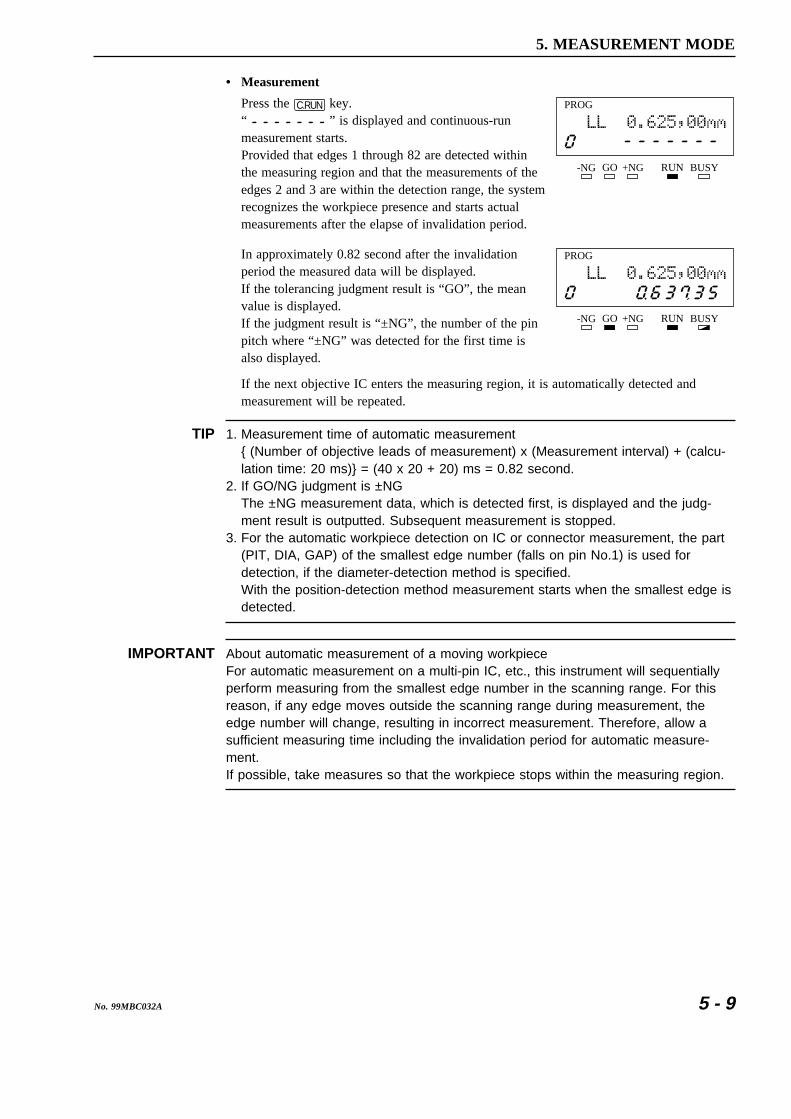
5 - 9No. 99MBC032A
5. MEASUREMENT MODE
• Measurement
PROG
BUSYRUN+NGGO-NG
Press the C.RUN key.“ ” is displayed and continuous-runmeasurement starts.Provided that edges 1 through 82 are detected withinthe measuring region and that the measurements of theedges 2 and 3 are within the detection range, the systemrecognizes the workpiece presence and starts actualmeasurements after the elapse of invalidation period.
PROG
BUSYRUN+NGGO-NG
In approximately 0.82 second after the invalidationperiod the measured data will be displayed.If the tolerancing judgment result is “GO”, the meanvalue is displayed.If the judgment result is “±NG”, the number of the pinpitch where “±NG” was detected for the first time isalso displayed.
If the next objective IC enters the measuring region, it is automatically detected andmeasurement will be repeated.
TIP 1. Measurement time of automatic measurement{ (Number of objective leads of measurement) x (Measurement interval) + (calcu-lation time: 20 ms)} = (40 x 20 + 20) ms = 0.82 second.
2. If GO/NG judgment is ±NGThe ±NG measurement data, which is detected first, is displayed and the judg-ment result is outputted. Subsequent measurement is stopped.
3. For the automatic workpiece detection on IC or connector measurement, the part(PIT, DIA, GAP) of the smallest edge number (falls on pin No.1) is used fordetection, if the diameter-detection method is specified.With the position-detection method measurement starts when the smallest edge isdetected.
IMPORTANT About automatic measurement of a moving workpieceFor automatic measurement on a multi-pin IC, etc., this instrument will sequentiallyperform measuring from the smallest edge number in the scanning range. For thisreason, if any edge moves outside the scanning range during measurement, theedge number will change, resulting in incorrect measurement. Therefore, allow asufficient measuring time including the invalidation period for automatic measure-ment.If possible, take measures so that the workpiece stops within the measuring region.

5 - 10 No. 99MBC032A
5.3.4 Applied Measurement with Offset/Zero-Set Functions
1. Applied measurement with offset function 1
Segment 1
Segment 2øD
Segment 3
[Figure a]
Laser scan directionThe offset function can be applied for convertingthe reference gage dimension to a nominal dimen-sion (Figure a).
In Figure a set the offset direction to “0” (positive).
Example of [figure a]
Let D = 20.0005 ± 0.0015 mm
• Basic setupSet up according to the requirement.
• Function setup1. Segment = 22. Number of scans for averaging = 5123. GO/NG judgment
a. Lower limit= 19.9985 mm
b. Upper limit= 20.0015 mm
4. Offseta. Set the nominal dimension of the gage to 20.0 mm.b. Direction = 0 (positive)
• Measurement
PROG
BUSYRUN+NGGO-NG
The ready state display appears as shown at the rightbefore the offset is set.
PROG
BUSYRUN+NGGO-NG
If the offset value is set to 20.0 mm, the guidancedisplay for the OFFSET guidance indicator ( ) turnson, and the measurement is also replaced to 20.0 mm.
PROG
BUSYRUN+NGGO-NG
Press the RUN key.“ ” is displayed and single-run measure-ment starts.After the first measurement interval the measurementvalue is displayed, and the GO/NG judgement result isoutputted.
TIP 1. To re-activate the offset function using the existing offset value and direction,press the MASTER / OFFSET key. With this single key operation, offset can be achieved.
2. It is possible to obtain a deviation from the reference gage by offsetting (zero-setting) it to “0.0”.

5 - 11No. 99MBC032A
5. MEASUREMENT MODE
2. Applied measurement with offset function 2
Laser scan direction
Reference piece
Segment 1
Reference surface
Workpiece
W
L
[Figure b]
The offset function is used to measure aworkpiece larger than the measuring rangeof this system.
In Figure b set the offset direction to “1”(negative).
Example of [figure b]
Let L = 50.0 ± 0.01 mm
• Basic setupSet up according to the requirement.
• Function setup1. Segment = 12. Number of scans for averaging = 5123. GO/NG judgment
a. Lower limit = 49.99 mmb. Upper limit = 50.01 mm
4. Offseta. Set to 50.0 mm.b. Direction = 1 (negative)
• Measurement
PROG
BUSYRUN+NGGO-NG
The ready state display appears as shown at the rightbefore the offset is set.Since the offset has not been set, the gap of segment 1is measured.
PROG
BUSYRUN+NGGO-NG
Set the offset to 50.0 mm. The measurement value isalso replaced by 50.0 mm.As the gap measurement is selected, set here thenegative direction (1).
PROG
BUSYRUN+NGGO-NG
Press the RUN key.“ ” is displayed and single-run measure-ment starts.After the first measurement interval the measured valueis displayed, and the GO/NG judgment result is output-ted.

5 - 12 No. 99MBC032A
3. Applied measurement with the zero-set function
WSegment 1 W0
Guide roller
T
[figure c]
Reference Piece
Use the zero-set function to easily measure atape thickness.
First measure segment 1 (W0) after removingthe tape from the guide roller, which is usedas a reference gage.
Set the tape as the measurement objective onthe guide, then measure segment 1 (W). Thetape thickness (T) is obtained from: T = (W0
- W)
For this measurement use the zero-setfunction.
Convert (zero-set) W0 to 0.0 mm and set the direction as 1 (negative). The following results:T = {W0 - (-W)} = 0.0 - (-W) = W
Here is an example of measuring a tape with a thickness of T = 0.1 ± 0.005 mm.
• Basic setupSet up as required.
• Function setup1. Segment = 12. Number of scans for averaging = 1283. GO/NG judgment
a. Lower limit = 0.095 mmb. Upper limit = 0.105 mm
• Measurement
PROG
BUSYRUN+NGGO-NG
Remove the tape and offset (zeroset) with “0.0”.Then set up the tape.The tape thickness will be displayed, however, GO/NGjudgment is not performed.
PROG
BUSYRUN+NGGO-NG
Press the C.RUN key.“ ” is displayed and continuous-runmeasurement starts.
PROG
BUSYRUN+NGGO-NG
At every measurement interval the measured data isdisplayed, and the GO/NG judgment result is outputted.Press the RUN key or C.RUN key.The most recent measurement is displayed, and mea-surement is stopped.

5 - 13No. 99MBC032A
5. MEASUREMENT MODE
5.3.5 Sample measurement
Segment 1
Segment 2
Runout: T
Segment 3
Knife-edge
Lase
r sc
an d
irect
ion
In addition to the diameter, a roller in a paper-feed mechanism requires a high machiningaccuracy with respect to both the roundness andcylindricity.
In this example suppose that the roller is beingturned to measure the runout.
In the diagram at the right the roller isturning, and the gap of segment 1 is mea-sured to determine the runout of T whilesegment 2 is measured to determine the OD.
This runout can be derived from the range(maximum - minimum) of sample measurements.
In this example a knife-edge is used for stablegap measurement, however, a round pin canalso be used if appropriate.
Here is an example of measuring a rubber roller with a diameter of ø25.0 ±0.05 mm and arunout tolerance of T = 0.03 mm.
• Basic setupSpecify simultaneous measurement.
• Function setup
metiputeS )dnuorgeroF(0margorP )dnuorgkcaB(5margorP
tnemgeS 1 2
rofsnacsforebmuNgnigareva
23 23
eulavtimilrewoL 0.0 59.42
eulavtimilreppU 30.0 50.52
elpmasforebmuN 05 05
metilacitsitatSegnar
)eulavmuminim-eulavmumixam(naem
denimretedsignigarevarofsnacsforebmuN.seerged063nahteromdenrutebtsumrellorrebburehT:ETON.rebmunelpmasehtdnadeepsnoituloverehtmorf

5 - 14 No. 99MBC032A
• Measurement
PROG
BUSYRUN+NGGO-NG
In the ready state the gap dimension of segment 1 isdisplayed.
PROG
BUSYRUN+NGGO-NG
Press the RUN key to start the measurement.“ ” is displayed and the sample measure-ment starts.
PROG
BUSYRUN+NGGO-NG
In this example the measurement result will be dis-played and the GO/NG judgment result will be outputapproximately 1 second after measurement starts.

5 - 15No. 99MBC032A
5. MEASUREMENT MODE
5.3.6 Applied measurement with automatic workpiece detection
If a workpiece of the specified range of dimension enters the measuring region, measurementwill be automatically started.
(a) (b) (c) (n) D
L
ba
Workpiece flow V mm/s
D = 5.0 ±0.0015 mm, L = 12 mm, chamfer a = 0.5 mm, b = 0.5 mm, and V = 50 mm/s.
• Basic setupSelect the OD detection method for automatic workpiece detection, and specify 16 for thedetecting speed (number of scans).
• Function setup1. Segment = 22. Number of scans for averaging = 256
Set to the maximum value of (Measurement interval) < (L- 2a) / V.3. GO/NG judgment
a. Lower limit = 4.9985 mmb. Upper limit = 5.0015 mm
4. Automatic workpiece detectiona. Number of measurements n = 1b. Invalidation period t = 50 ms t > (a / V)c. Lower detection limit L = 4.9 mm
Set using the dimension excluding the chamfered portion.d. Upper detection limit H = 5.1 mm
NOTE About automatic workpiece detectionIf sequentially fed workpieces have a small chamfer and they are almost in contact,workpieces may not be clearly identified. If this is the case, use connection rods, forexample, for adequate intervals.In addition, allow a sufficient margin for the invalidation period and upper and lowerdetection limits.

5 - 16 No. 99MBC032A
• Measurement
PROG
BUSYRUN+NGGO-NG
The diagram at the right indicates that no workpiece ispresent in the measuring region in the ready state.
PROG
BUSYRUN+NGGO-NG
Press the C.RUN key to start continuous measurementwhile changing the display from “ ” to“ .” If workpiece (a) enters the measur-ing region, OD measurement will automatically bestarted.
If the OD measurement resulting from 16 scans iswithin the preset limits, a workpiece is judged as beingpresent (“workpiece present”). The system waits untilthe specified invalidation period elapses.
PROG
BUSYRUN+NGGO-NG
After the invalidation period elapses, OD measurementof workpiece (a) is started. At every measurementinterval the measured data will be displayed and theGO/NG judgment results will be output.
PROG
BUSYRUN+NGGO-NG
Measurement of workpiece (b) entered.As with workpiece (a) measurement is performed andthe results are displayed.
PROG
BUSYRUN+NGGO-NG
Workpieces that enter the measuring region are mea-sured sequentially.
PROG
BUSYRUN+NGGO-NG
To terminate measurement, press the RUN key or
C.RUN key again.The most recently measured data will be displayed.

5 - 17No. 99MBC032A
5. MEASUREMENT MODE
5.3.7 Applied measurement on a stepped round bar
øA øBIn this example 10 stepped round bars are measuredand the results are statistically processed. If ±NGmeasurement is obtained, it will be automaticallyprinted out.In the figure at the right suppose the following:øA: ø6 ±0.01 mmøB: ø10h70
-0.015 mm
• Basic setup1. Set the resolution to 0.1 µm.2. Specify the RS-232C port as the printer port.
• Function setup
metiputeS )dnuorgeroF(0margorP )dnuorgkcab(1margorP
tnemgeS 2 2
rofsnacsforebmuNgnigareva
215 215
eulavtimilrewoL 99.5 589.9
eulavtimilreppU 10.6 0.01
noitidnoctuptuoataD 2 2
noitidnocrehtO )lecnac(0 )lecnac(0
• Preparation for measurementPress the SHIFT and A.CL / M.CL keys to clear all of the statistical memory, then press the
STAT / S.E key to start statistical processing. If the statistical processing mode is entered,the S.E. guidance indicator ( ) turns on.
PROG
BUSYRUN+NGGO-NG
• MeasurementPerform a single-run measurement for the A dimensionby program No.0 after setting the workpiece in place.The measured data will be displayed and the GO/NGjudgment result will be outputted.
PROG
BUSYRUN+NGGO-NG
Change to Program No.1 for the B dimension to bemeasured through single-run measurement.The measured data will be displayed and the GO/NGjudgment result will be outputted.
PROG
BUSYRUN+NGGO-NG
Change the workpiece and repeat the same measure-ments.
PROG
BUSYRUN+NGGO-NG
If the result is ±NG, it will be automatically printed out.

5 - 18 No. 99MBC032A
• Confirming the statistical data on the display (not always required)
PROG
BUSYRUN+NGGO-NG
Press the SHIFT and STAT / S.E keys in the ready stateto enter the statistical display mode for Program No.0.If this mode is entered, the number of samples isdisplayed first.
Each time the ENT key is pressed, the statistical processing item changes in the followingorder: Number of samples: → Standard deviation: → Maximum value: →Minimum value: → Mean: → Range: → Number of samples: .
PROG
BUSYRUN+NGGO-NG
Press the SHIFT and STAT / S.E keys to return to theready state, and confirm the statistical data of ProgramNo.1 in the same way.
• Printing the statistical dataUse the SHIFT and S.PR / PRINT keys to print out the statistical data. This automaticallyclears all of the statistical memory after printout.An example printout is shown below.
An example printout
P:0P:1P:0P:1STAT.
-NG-NG+NG+NGDATA
5.989,9 5.984,9 6.010,1 10.000,1
PROGRAM NO. = NAVGMAXMIN RS.D
0 106.003,26.010,45.989,90.020,50.007,85
PROGRAM NO. = NAVGMAXMIN RS.D
1 10 9.993,6 10.000,1 9.984,9 0.015,2 0.006,99
STAT. DATA

6
6 - 1No. 99MBC032A
This chapter describes the setup method and functions provided with theRS-232C interface and Digimatic output interface of this unit.
INTERFACE UNIT
6.1 RS-232C InterfaceThe standard RS-232C interface of this Display Unit allows the LSM to communicate withexternal devices via RS-232C (EIA standard) serial signals.
Prior to using this interface , set up the baud rate, data bits, and parity check, etc. accordingto Section 4.1, “Basic Setup”. The setting contents must be compatible to that on the externaldevice to be connected.
6.1.1 Specifications
• Applicable plug connector: D-sub 9 pin (female) (Manufacturer: AMP, HD-20/747951-1)or equivalent.
6 9
1 5
The pin numbering for this system is shown at the left
• Communication specifications
Device definition
Communication method
Synchronizing method
Baud rate
Data configuration
Specify the LSM as a terminal (DTE)
Full-duplex
Start/stop method (asynchronous)
1200, 2400, 4800, 9600, 19200 bps
Transmission code
Data bits
Start bit
Stop bit
Parity check
Delimiter
ASCII
7 or 8 bits
1 bit
1 bit
None, odd, or even
CR+LF, CR, LF

6 - 2 No. 99MBC032A
NOTE 1. The shaded settings are the factory defaults.2. In the above table “none parity” can not be selected if the data bits are 7 bits in
length. In this case, set the parity to either odd or even, or set the data bits to 8bits.
TIP 1. DTR and RTS signals from the LSM will be ON immediately after power on.2. DSR signals to the LSM are always ignored.3. The transmitter-receiver inside the LSM uses a µPD4723 (Manufacturer: NEC).

6 - 3No. 99MBC032A
6. INTERFACE UNIT
6.1.2 Connections
(1) Connecting the RS-232C interface to a device specified as a terminal (DTE)
Example 1 Flow control method (handshake method controlled by CTS, DSR, DTR, and RTS signals)
1
2
5
6
7
8
3
4
9
1
2
5
6
7
8
9
3
4
SG
RI
RxD
DCD
CTS
TxD
DTR
DSR
RTS
SG
RxD
CTS
TxD
DTR
DSR
RTS
Signal namePin No.Pin No.Signal name
LSM: specified as a terminal (DTE)
9-pin D-sub9-pin D-sub
Personal computer (PC-AT compatible) specified as a terminal (DTE)
Example 2 Flow control method (handshake method controlled by CTS, DSR, DTR, and RTS signals)
1
2
5
6
7
8
3
4
9
1
2
5
6
7
8
20
3
4
FG
SG
TxD
DCD
CTS
RxD
RTS
DSR
DTR
SG
RxD
CTS
TxD
DTR
DSR
RTS
Signal namePin No.Pin No.Signal name
9-pin D-sub25-pin D-sub
LSM: specified as a terminal (DTE)Personal computer (PC-9801) specified as a terminal (DTE)
Example 3 3-Wire method (teletype protocol using TxD, RxD and SG)
1
2
5
6
7
8
3
4
9
1
2
5
6
7
8
9
3
4
SG
RI
RxD
DCD
CTS
TxD
DTR
DSR
RTS
SG
RxD
CTS
TxD
DTR
DSR
RTS
Signal namePin No.Pin No.Signal name
9-pin D-sub9-pin D-sub
LSM: specified as a terminal (DTE)Personal computer (PC-AT compatible) specified as a terminal (DTE)

6 - 4 No. 99MBC032A
(2) Connecting the RS-232C interface to a device specified as a modem (DCE)
Example 1 Flow control method (handshake method controlled by CTS, DSR, DTR, and RTS signals)
1
2
5
6
7
8
3
4
9
1
2
5
6
7
8
9
3
4
SG
RI
RxD
DCD
CTS
TxD
DTR
DSR
RTS
SG
RxD
CTS
TxD
DTR
DSR
RTS
Signal namePin No.Pin No.Signal name
LSM: specified as a terminal (DTE)
9-pin D-sub9-pin D-sub
Device specified as a modem (DCE)
Example 2 DPU-414: Printer (controlled by RTS signal)The DPU-414 series printer (Manufacturer: Seiko Electronics Co., Ltd.) shouldbe connected as follows:
1
2
5
6
7
8
3
4
9
1
2
5
6
7
8
9
3
4
SG
TxD
RTS
RxD
*1
*1
SG
RxD
CTS
TxD
DTR
DSR
RTS
Signal namePin No.Pin No.Signal name
LSM: Defined as terminal (DTE)
*1: Pin Nos. 4 and 6 of the printer-side connector are internally connected.*2: Possible to use a straight-type cable (In this case, it is not necesary to install wirings shown by the dotted lines) .
9-pin D-sub9-pin D-sub
DPU-414 series printer
IMPORTANT 1. The signals names and pin assignment described here may be different from thatof the user’s devices. Refer to the user’s manual of your own device whenmaking connections.
2. For this connection always use cables that have a shielding net. Both ends of thisshielding net should be connected (grounded) to the RS-232C connector case.Without using a shielded-wire this system may experience electrical interferenceresulting in operation errors. Or, radio frequency will be emitted from this systemand interfere the electrical equipment such as TVs, etc.

6 - 5No. 99MBC032A
6. INTERFACE UNIT
6.1.3 Printer interface
6.1.3.1 Setting the printer
• RS-232C can be set as a printer port in the basic setup mode.• DPU-414 series printers from Seiko are compatible.• Use a supplied connection cable which comes with the printer.• DPU-414 series printer setup (Refer to the DPU-414 operation manual: the section 2.3,
“Functions setup” on the page 15 through 20.)
1) Software Dip Switches Setup
Set the DIP SW 1 to 3 as shown bellow.
SW1 : 1 2 3 4 5 6 7 80 1 1 0 1 0 1 1 (1 : on, 0 : off)
SW2 : 1 2 3 4 5 6 7 81 1 1 1 1 1 1 1 (1 : on, 0 : off)
SW3 : 1 2 3 4 5 6 7 81 1 1 1 0 1 1 1 (1 : on, 0 : off)
2) The method of Software Switches setup
a. Switch on the power while pressing the [ON LINE] key, releasing it when printing isstarted. Current setup condition will be printed out.
b. Press the [ON LINE] key. “Dip SW-1” is printed out. Set the DIP SW 1: bit 1 to 8 here.
NOTE • Complete setting of DIP SW 1: bit 1 to 8 at a stretch. Don’t stop it halfway.• [FEED] key and [ON LINE] key are assigned to “0” (off) and “1” (on) for setting
respectively.
Press both [FEED] and [ON LINE] keys in order as specified bellow.[FEED][ON LINE][ON LINE][FEED][ON LINE][FEED][ON LINE][ON LINE]
(Print) 0 1 1 0 1 0 1 1
c. When setting DIP SW 1: bit 1 to 8 is complete in the item b., “Continue? :Push ‘On-lineSW’ ”, “Write? :Push ‘Paper feed SW’ ” will be printed out. Then press [On LINE] key toproceed to setup DIP SW2. “Dip-SW-2” is printed out. Here, start setting of DIP SW2.
d. For DIP SW2 setting, press both [FEED] and [ON LINE] keys in order as specifiedbellow.
[ON LINE][ON LINE][ON LINE][ON LINE][ON LINE][ON LINE][ON LINE][ON LINE]
(Print) 1 1 1 1 1 1 1 1
When setting DIP SW2: bit 1 to 8 is complete, same as item c. “Continue? :Push ‘On-lineSW’ ”, “Write? :Push ‘Paper feed SW’” will be printed out. Then press [On LINE] key toproceed to setup DIP SW3. “Dip-SW-3” is printed out. Here, start setting of DIP SW3.
e. For DIP SW3 setting, press both [FEED] and [ON LINE] keys in order as specifiedbellow.
[ON LINE][ON LINE][ON LINE][ON LINE][FEED][ON LINE][ON LINE][ON LINE]
(Print) 1 1 1 1 0 1 1 1
When setting DIP SW3: bit 1 to 8 is complete, press [FEED] key. DIP SW 1 to 3 settingwill be complete.

6 - 6 No. 99MBC032A
6.1.3.2 Setting the LSM-9506
The following setting for LSM-9506 needs to be set in the Basic Setup mode and Setting Upthe Functions mode.
1) Basic Setup (Refer to the section 4.1, “Basic Setup” and 4.1.2.5, “Selecting and setting thefunction in the B4 mode”.)
a. Setting the use of the RS232C port RS-232C : PRN
b. Setting the RS232C communication baud rate BAUD : 9600
c. Setting the RS232C communication data bits LENGTH : 8
d. Setting the RS232C communication parity bit PARITY : NONE
e. Setting the delimiter for communication DELIMT : CR+LF
f. Setting the RS232C line control CONTRL : USE
2) Setting Up the Functions (Refer to the section 4.5, “Setting Up the Functions” and 4.5.3.6,“F5: Setting the data output conditions”.)
DAT O.C : 1 (Printing for each measurement)
DAT TIM : 0 (Printing all)
Connect with the printer after setup is complete. Press [Print] key to start measurement andprinting measured data.
6.1.4 RS-232C commands
• This section describes the reception commands used by the RS-232C interface and theresponse (transmission) commands that correspond to the reception commands. The datasection of each command consists of ASCII codes.
• Use the following command subscriptions, symbols and supplement descriptions when youread Section 6.1.5, “List of commands”.
• Command symbols
Symbol Meaning Entry of numeral
Combination using numbers between 1 and 7Select a number between 1 and 255However, aaa should not be identical to bbb.
Segment numberStart edge and finish edge of the edge specificationaaa: Start edge, bbb: Finish edge
Setup data or measured data
Measurement interval number
Data output condition
Periodical output timer value (sec)
Invalidation period of automatic workpiece detection (msec)
Number of measurement times of sample measurement
Number of measurement times of automatic workpiece detection
Number of scans for averaging
Group size subject to judgment
Space character
Maximum of 7 significant digits
Select a number between 1 and 4
Select a number between 0 and 9
Select a number between 0 and 999
Select a number between 0 and 9999
Select a number between 0 and 999
Select a number between 1 and 999
2 (select between n=0 and 11)
Select a number between 0, 1, 2 and 99
sssssssaaa-bbb
±ddd.dddd
Program Number Select a number between 0 and 9p
m
r
nnn
ttt
nn
SHL (Threshold level) specification (%) Select between 50% and 90%pp
mmm
nnnn
Δ
n
tttt

6 - 7No. 99MBC032A
6. INTERFACE UNIT
TIP 1. To ensure compatibility with the LSM-9506, this system ignores the followingcommands without treating them as ER6, but uses “OK”.• Memory switch command (UP0 uvxyz, UP1 uvxyz, UP2 uvxyz)• The MNL command is assumed to be identical to the MNH command.
2. If the setup data is “0”, it allows the corresponding function to be disabled. To set“0” as a numerical value, use “0.0”.
Example 1 “SET, OF0” ................... Offset function is disabled.Example 2 “SET, OF0.0” ................ Offset function is enabled.
3. Setup data or measured data is denoted by ±ddd.dddd.• The first (most significant) digit is a sign. For commands that do not specifically
designate the polarity, such as the calibration command, only a positive sign isaccepted. However, these positive signs do not have to be specified.
• Any decimal place is selectable.An integer can be entered without using a decimal point.
4. For making the setup operation of the measurement interval easier, use themeasurement interval number as shown below. For the correspondence betweenthe actual number of scans and the measurement interval numbers see the tablebelow.
Measurement interval number Number of scans for averaging
16 times
64 times
256 times
1
2
3
Measurement interval
0.01 sec
0.04 sec
0.16 sec
512 times4 0.32 sec
5. “Pp” command can be appended to the following commands to be treated as asingle command: “SET”, “R”, “CR”, “STAT”, “RP”.Example: P0, R
P6, STAT
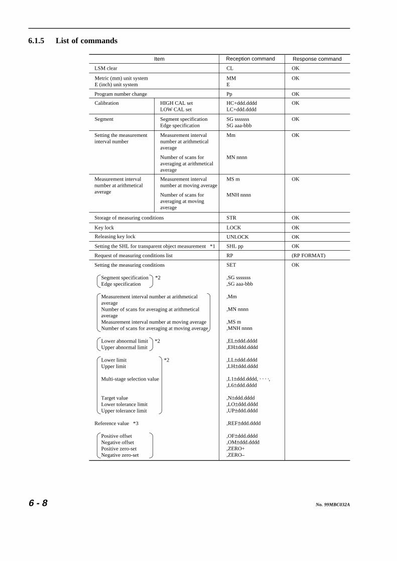
6 - 8 No. 99MBC032A
6.1.5 List of commands
Item Reception command Response command
OKCL
MME
HC+ddd.ddddLC+ddd.dddd
Mm
STR
LOCK
UNLOCK
SHL pp
RP
SET
,SG sssssss,SG aaa-bbb
,Mm
,MN nnnn
,MS m,MNH nnnn
,EL±ddd.dddd,EH±ddd.dddd
,LL±ddd.dddd,LH±ddd.dddd
,L1±ddd.dddd, · · · ·,,L6±ddd.dddd
,N±ddd.dddd,LO±ddd.dddd,UP±ddd.dddd
,REF±ddd.dddd
,OF±ddd.dddd,OM±ddd.dddd,ZERO+,ZERO–
OK
OK
OK
MN nnnn
MS m OK
MNH nnnn
OK
OK
OK
OK
(RP FORMAT)
LSM clear
Program number change
Metric (mm) unit systemE (inch) unit system
Calibration
Setting the measurementinterval number
Measurement intervalnumber at arithmeticalaverage
Storage of measuring conditions
Key lock
Request of measuring conditions list
Releasing key lock
Setting the SHL for transparent object measurement *1
Setting the measuring conditions
Segment specification *2 Edge specification
Measurement interval number at arithmetical average Number of scans for averaging at arithmetical average Measurement interval number at moving average Number of scans for averaging at moving average
Lower abnormal limit *2 Upper abnormal limit
Lower limit *2 Upper limit
Multi-stage selection value
Target value Lower tolerance limit Upper tolerance limit
Reference value *3
Positive offset Negative offset Positive zero-set Negative zero-set
SG sssssssSG aaa-bbb
OKSegment
HIGH CAL setLOW CAL set
Segment specificationEdge specification
Measurement interval number at arithmetical average
Number of scans for averaging at arithmetical average
Measurement interval number at moving average
Number of scans for averaging at moving average
OK
OKPp

6 - 9No. 99MBC032A
6. INTERFACE UNIT
,PR r
,PRT ttt
,SMP nnn
,(MAX,MIN,RNG,AVG)
,GN nn,GLL±ddd.dddd,GLH±ddd.dddd
,(GMX,GMN,GAG,GRG)
Data output conditions
Periodic data output conditionsPeriodic output timer
Number of sample measurementsSetting the statistical item for sample measurement(Maximum value, minimum value, range, mean)
Group sizes subject to judgment *2 Lower tolerance limit for group judgment Upper tolerance limit for group judgment Statistical item for group judgment (Maximum value, minimum value, mean, range)
OK
Item Reception command Response command
(DATA FORMAT)R
CR
CL
D
ST
NST
(DATA FORMAT) *4
OK
(DATA FORMAT)
OK
OK
Start of single-run measurement
Continuous-runmeasurement
Request of measurement data
R
STOP
No response command
(DATA FORMAT)
Zero-run measurement
Measurement startcommandMeasurement stopcommand
Measurement startcommandMeasurement stopcommand
Statistical processingcalculation
Performs statisticalprocessingDoes not performstatistical processing
Current program only
All programs
Erasing the statistical processing memory
MC
MCAL
OK
Request of statistical processing results STAT (STAT FORMAT)
Condition setting of automatic workpiece detection *2• Number of measurement times• Invalidation period• Lower detection limit• Upper detection limit
Request of conditions list for automatic workpiecedetection
RA (RA FORMAT)
*1: • Do not use the SHL command unnecessarily unless there is a need to change the threshold voltage because of the *1: • workpiece property, since it adversely affects the measuring accuracy. *1: • In order to restore the standard threshold voltage, enter the following command:*1: • “SHL50” Resets to 50%, which is the standard.*1: • “STR” Records the value in memory.*1: • The SHL command will be effective if the transparent measurement is selected in the basic setup mode.*2: Designating any command of the functions which are set to “Not used” in the basic setup will result in ER6.*3: If “Copying the target value to the reference value” is specified in the basic setup, designating this command results*1: in ER-6.*4: Responds with measurements according to the data output conditions.
Automatic workpiece detection control *2 AUT, S OK
AUT,N mmm,D tttt,L±ddd.dddd,H±ddd.dddd
OK
*2

6 - 10 No. 99MBC032A
6.1.6 List of response commands if an error occurs
Response command Description
A workpiece is not present in the specified segment.• A workpiece is not set properly.• Shutter is closed.
Parity error occurred.• Check the setup contents in the basic setup.• Isolate the cables from noise sources.
All setup data are initialized (cleared) when the power is ON.
A numeric value greatly different from the reference gage dimension is set.
• Limit values for go/no-go judgment and abnormal data exclusion have been set in reverse order or equal.• Input value is too large.
An unavailable command is received.• Command format is incorrect.• Baud rate and/or data bits are not consistent.
Message from the external device• Measurement is interrupted by signal input from key operation.
ER0
ER1
ER2
ER9
ER5
ER6
ER7

6 - 11No. 99MBC032A
6. INTERFACE UNIT
6.1.7 Format of response commands
1) (DATA FORMAT): Data format (maximum 38 characters)
Pp, (GO/NG judgment result) ±ddd.dddd (, deviation)
a. Where the GO/NG judgment is active, GO/NG judgment result (-NG, OK or +NG) willbe appended.
b. Where the reference value is set, a deviation (, DEV±ddd.dddd) is appended.This deviation value is derived from (Measured data - Reference value).
c. In the simultaneous measurement the foreground measurement is followed by thebackground measurement after a comma (,) is inserted between them.
2) (RP FORMAT): Report format (maximum 107 characters)PROGRAM, Pp, SG sssssss, Mm, LL ±ddd.dddd, LH ±ddd.dddd, REF ±ddd.dddd,OF ±ddd.dddd, PR r, PRTttt, SMPnnn, AVG, ST
• A maximum of 107 characters will result from the above described specification, however,it varies depending on the setup.a. A maximum of 5 characters are to be added if the number of averages is specified.b. A maximum of 8 characters are to be added if (target value + tolerance) is specified.c. A maximum of 52 characters are to be added if the multi-stage selection is specified.d. A maximum of 32 characters are to be added if the abnormal value eliminating function
is specified.Between MM and LL “EL ±ddd.dddd, EH ±ddd.dddd” is inserted.
• Available symbols may change depending on the setup contents.a. SG sssssss → SG aaa-bbbb. Mm → Mnnnnn, Msm or MNHnnnnc. LL ~ LH ±ddd.dddd → N ±ddd.dddd, LO ±ddd.dddd, UP ±ddd.dddd
→ L1 ±ddd.dddd, .................. , L6 ±ddd.dddde. OF ±ddd.dddd → OM ±ddd.ddddf. AVG → MAX, MIN or RNGg. ST → NST
3) (STAT FORMAT): Statistical data format (maximum 86 characters)STAT DATA, Pp, Nnnnnnn, AVG±ddd.dddd, MAX±ddd.dddd, MIN±ddd.dddd,RNGddd.dddd,S.Dddd.dddd
• “nnnnnn” implies the number of statistical data pieces, which is maximum 100,000. Datapieces that exceed this limit will be excluded from the statistical data.
4) (RA FORMAT) : Data format for automatic workpiece detection (maximum 36 characters)AUT, Nmmm, Dtttt, L±ddd.dddd, H±ddd.dddd
TIP 1. The integer section of “±ddd.dddd” will be zero-suppressed.2. The “±” section will be “-” if the value is negative, and will be removed (the follow-
ing digits are left-flushed) if the value is positive.

6 - 12 No. 99MBC032A
6.1.8 Other commands
1) Each of the D, R, and CR commands can be appended with an “N”.If appended with an “N”, each program number will be removed from these commands.
Item Reception command
Data request
Single-run measurement (zero-run measurement)
Continuous-run measurement
DN
RN
CRN
Example: “D” → “P0, 12.3456” : Appended with a program number“DN” → “12.3456” : Program number is removed.
2) Each of the D, R, CR, RP, STAT, and RA commands can be appended with an “*”.If appended with an “*”, these commands have a fixed data length that is not zero-sup-pressed.
Item Reception command
Data request
Single-run measurement (zero-run measurement)
Continuous-run measurement
Request of measuring conditions list
Request of statistical processing results
Request of automatic workpiece detection conditions list
*D*DN
*R*RN
*CR*CRN
*RP
*STAT
*RA
Example: “D” → “P0, 12.3456” : Zero suppressed.“*D” → “P0, +012.3456” : Outputted in 7 digits without zero suppressing.

6 - 13No. 99MBC032A
6. INTERFACE UNIT
6.1.9 Details of command descriptions
(1) CL
(a) Format: CL(b) Description: Functions same as the C key on the Display Unit.
This releases the error state, performs single-run measurement, zero-runmeasurement, continuous-run measurement, and releases the measurementresult display latch.
(c) Example: Reception command CLTransmission command OK
(2) MM, E
(a) Format: MME
(b) Description: MM: Sets the display unit to mm.E: Sets the display unit to E (inch).
(c) Example: Reception command MM or ETransmission command OK
(3) P
(a) Format: Pp (p: program number)(b) Description: Program number is changed to the specified one.(c) Example: Reception command P5
Transmission command OK
(4) HC, LC
(a) Format: HC+ddd.ddddLC+ddd.dddd
(b) Description: Calibrates the LSM.If the supplied gage is set in position and this command is executed, theproportion of the actually measured gage dimension to the entered value iscalculated and the resultant constant is stored in memory, then the “OK”response will be issued. It requires approximately a second.
(c) Example: Reception command HC24.0005 Transmission command OKReception command LC 0.9995 Transmission command OK
(d) Supplement: Negative setup data results in ER2

6 - 14 No. 99MBC032A
(5) SG sssssss, SG aaa-bbb
(a) Format: SG sssssss (sssssss: SEG No. Number of digits should be between 1 and 7.Duplicated number must not be specified.)SG aaa-bbb (aaa: start edge, bbb: finish edge. The range is between 1 and 255for both edges. However, aaa should not be identical to bbb.)
(b) Description: Setting the segment (measuring position).Two types of setting are available; segment specification and edge specification.
(c) Example: Reception command SG2 Response command OKReception command SG2-65 Response command OK
(d) Supplement: • Segments and edges should be set in the basic setup.• sssssss can be set with 7 digits or less.
Ex.) SG 1234567, SG 24, SG3, etc.• aaa and bbb should be set within 3 digits.
Ex.) SG1-2, SG 2-33, SG 111-255, etc.The order of the start edge and finish edge can be reversed.
(6) M
(a) Format: M m (m: measurement interval number, 1 to 4)(b) Description: Set the averaging method to the arithmetical average, and set a number between
1 and 4 for the representative measurement interval numbers. With thesemeasurement interval numbers compatibility with the conventional models isensured.
(c) Example: Reception command M4Response command OK
(d) Supplement: Relationship between the measurement interval number, measurement interval,and number of scans for averaging is as follows:
Measurement interval number Number of scans for averaging
16 times
64 times
256 times
1
2
3
Measurement interval
0.01 sec
0.04 sec
0.16 sec
512 times4 0.32 sec
(7) MN
(a) Format: MN nnnn (nnnn: Number of scans, between 1 and 2048)(b) Description: Set the averaging method to the arithmetical average, and specify the number
of scans to nnnn (2n, where n= 0 to 11).(c) Example: Reception command MN 1024
Response command OK
(8) MS
(a) Format: MS m (m: Measurement interval number, between 2 and 4)(b) Description: Set the averaging method to the moving average, and specify a measurement
interval number to ensure compatibility with conventional models.(c) Example: Reception command MS4
Response command OK(d) Supplement: Relationship between the measurement interval number, measurement interval,
and number of scans for averaging is as follows:

6 - 15No. 99MBC032A
6. INTERFACE UNIT
Measurement interval number Number of scans for averaging
64 times
256 times
2
3
1st measurement interval
0.04 sec
0.16 sec
512 times4 0.32 sec
2nd measurement interval
0.01 sec
0.01 sec
0.01 sec
(9) MNH
(a) Format: MNH nnnn(nnnn: Number of scans, between 32 and 2048)(b) Description: Set the averaging method to the moving average, and specify the number of
scans with nnnn. nnnn is 2n, where n= 5 to 11.(c) Example: Reception command MNH 1024
Response command OK(d) Supplement: MNL command is as same as MNH command
(10) STR
(a) Format: STR(b) Description: Data that has been set by the RS-232C command will be erased from memory
if the power is off. To retain the data after the power off, use this command tosave the critical measuring conditions in memory. But the “ST” and “NST”command will not be saved.
(c) Example: Reception command STRResponse command OK
(11) LOCK
(a) Format: LOCK(b) Description: Locks the keyboard of this machine to prevent accidental operation.
To release this key lock state, use the UNLOCK command.(c) Example: Reception command LOCK
Response command OK(d) Supplement: Lock set by this command can not be released with key operation.
(12) UNLOCK
(a) Format: UNLOCK(b) Description: Releases the key lock state and enables key operations again.(c) Example: Reception command UNLOCK
Response command OK
(13) SHL
(a) Format: SHL pp (pp: threshold level, 50 to 90%)(b) Description: If “Performing the ultra-fine wire measurement” is specified in the basic setup,
designating this command results in ER6.Used to measure such as the width of a tape, which has a good transparency.
(c) Example: Reception command SHLResponse command OK
(d) Supplement: Refer to Section 3.2.4.1, “Transparent object (Workpiece that transmits light)”.

6 - 16 No. 99MBC032A
(14) RP (RP FORMAT)
(a) Format: RP(b) Description: This is used to confirm the setup contents, if the measuring conditions and
operating conditions set are received as the response.(c) Example: Reception command RP command
Response command PROGRAM, SG 2, M3, LL D 5.988, LH 6.010,REF6.000, OF 0, PR 3, PRT0, SMP20, MAX, ST
(15) SET
(a) Format: SETSegment specification *1 , SG sssssssEdge specification *1 , SG aaa-bbb
Measurement interval number at arithmetical average , M mNumber of scans for arithmetical average , MN nnnnMeasurement interval number at moving average , MS mNumber of scans for moving average , MNH nnnn
Lower abnormal limit *2 , EL±ddd.ddddUpper abnormal limit *2 , EH±ddd.dddd
Lower limit *1 , LL±ddd.ddddUpper limit *1 , LH±ddd.dddd
, L1±ddd.ddddMulti-limit selection value *1 , L2 • • • •
, L6±ddd.dddd
Target value *1 , N±ddd.ddddLower tolerance limit *1 , LO±ddd.ddddUpper tolerance limit *1 , UP±ddd.dddd
Reference value *3 , REF±ddd.dddd
Positive offset *4 , OF±ddd.ddddNegative offset *4 , OM±ddd.ddddPositive zero-set *4 , ZERO+Negative zero-set *4 , ZERO–
Data output condition *5 , PRrPeriodic data output timer , PRT ttt
Number of sample measurements , SMP nnnSample measurement • Maximum value *6 , MAX
• Minimum value *6 , MIN• Range *6 , RNG• Mean *6 , AVG
Group size subject to judgment *2 , GN nnLower tolerance limit of group judgment *2 , GLL±ddd.ddddUpper tolerance limit of group judgment *2 , GLH±ddd.ddddStatistical items for group judgment : Maximum value *2, 6 , GMX
: Minimum value *2, 6 , GMN: Mean *2, 6 , GAG: Range *2, 6 , GRG

6 - 17No. 99MBC032A
6. INTERFACE UNIT
(b) Description: This sets the measuring conditions.• Each of the commands that follow the SET command must be delimited by a
comma (,).• A command which doesn’t need a setting change can be eliminated.• Approximately 0.5 second is required for this command to be processed.
(c) Example: Reception command SET, SG2, M4, LL 5.988, LH 6.010, REF6.000, OM 0,PR 3, PRT10
*1: Select either setup method in the basic setup.*2: This is valid only if the function is specified in the basic setup.*3: This is valid only if the “Copying the target value to the reference value” is specified in
the basic setup.*4: Set the reference gage on the Measuring Unit before sending this command. These
commands will spend approximately 1 second for processing. The settings of eachfunction are as follows:• Positive offset: Offsetting in the positive (0) direction.• Negative offset: Offsetting in the negative (1) direction.• Positive zero-set: Zero-setting in the positive (0) direction.• Negative zero-set: Zero-setting in the positive (0) direction.
*5: “PRr” is used to set the data output conditions for the RS-232C (printer) or DigimaticOutput Unit interface. If the PR number is 1, 3 or 5, it is possible to set the periodicoutput timer, and the data output interval can be selected from 0 (for each measure-ment) and between 1 and 999 seconds.The PR numbers and the data output conditions have the following relationships.
Data output condition(PR No.)
PrinterRS-232CDCU
Remark
The periodical output timer can be set
0
1
2
7
— —
—
—
—
—
8
9
6
The periodical output timer can be set5
4
The periodical output timer can be set3
: Outputs data for each measurement. : Performs measurement and outputs data when a GO measurement results. : Performs measurement and outputs data when a ±NG measurement results. : No output
—
—
—
*6: Only one of these statistical items can be specified.

6 - 18 No. 99MBC032A
(16) R
(a) Format: R(b) Description: If the number of samples is set between 1 and 999, this command executes
single-run measurement and transmits the measurement result in conformitywith DATA FORMAT as the response command.
(c) Example: Reception command RResponse command P0, 12.3456
(17) CR, CL
(a) Format: CRCL
(b) Description: CR: If the number of samples is set between 1 and 999, this command executescontinuous-run measurement. However, it does not respond to the “CR”command.
• It transmits the measured results in conformity with DATA FORMAT forthe response command.
CL: Terminates continuous-run measurement.(c) Example: Reception command Response command
CR None• Outputs as the response, the measurement results according to the data
output conditions in conformity with DATA FORMAT.CL OK
(18) R, STOP
(a) Format: RSTOP
(b) Description: R: If the number of samples is set to 0, this command executes zero-runmeasurement. However, it does not respond to “R” command.
STOP:Terminates the zero-run measurement, and transmits the measurementresults in conformity with DATA FORMAT as the response.
(c) Example: Reception command RSTOP
Response command P0, 12.3456
(19) D
(a) Format: D(b) Description: Transmits as the response the last display of data in the ready state or latched
data not in conformity with DATA FORMAT.This command is used to transmit the previous data, while the R command isused to execute measurement then the results are transmitted.
(c) Example: Reception command DResponse command (DATA FORMAT)

6 - 19No. 99MBC032A
6. INTERFACE UNIT
(20) ST, NST
(a) Format: STNST
(b) Description: ST : Performs statistical processing. However, measurements obtained in theready state will be omitted from the objectives of statistical processing.
NST: Terminates the statistical processing.(c) Example: Reception command ST or NST
Response command OK
(21) MC, MCAL
(a) Format: MCMCAL
(b) Description: Both the MC and MCAL commands are used to clear the statistical memory.This operation is required before starting statistical processing.
(c) Example: Reception command MC or MCALResponse command OK
(22) STAT
(a) Format: STAT(b) Description: Requests the statistical processing data. The statistical processing data will be
cleared when the power is off.(c) Example: Reception command STAT
Response command STAT DATA, N100, AVG12.0001, MAX12.0005,MIN11.9998, RNG0.0007, S.D0.00007
(23) AUT
(a) Format: AUT, Nmmm, Dtttt, L±ddd.dddd, H±ddd.dddd(b) Description: Set the conditions of automatic workpiece detection with the following data to
follow “AUT” and delimited by a comma (,).Lower and upper detection limits for the position detection method do notrequire a “-” sign, so it will be ignored if specified.• Responds only when the automatic workpiece detection has been set in the
basic setup.• N mmm (mmm: number of measurement times between 1 and 999. If “0” is
specified, automatic workpiece detection is not performed.)• Dtttt (tttt: Invalidation period between 0 and 9999 ms)• L±ddd.dddd (±ddd.dddd: Lower detection limit)• H±ddd.dddd (±ddd.dddd: Upper detection limit)
(c) Example: Reception command AUT, N50, D15, L9.5, H12.3Response command OK

6 - 20 No. 99MBC032A
(24) AUT, S
(a) Format: AUT, S(b) Description: Where “Performing the automatic workpiece detection” is specified in the basic
setup, and if this command is received, “S” will be responded each time aworkpiece is detected.If this setup is not made in the basic setup, designating this command resultsin ER6.
(c) Example: Reception command AUT, SResponse command OK
(25) RA
(a) Format: RA(b) Description: Transmits as the response the conditions of the automatic workpiece detection
using RA FORMAT.(c) Example: Reception command RA
Response command AUT, N50, D15, L9.5, H12.3
(26) Timing signal
If the measuring operation is interrupted by a command from the key operation, an ER7 will beresponded to the RS-232C interface.

6 - 21No. 99MBC032A
6. INTERFACE UNIT
6.1.10 An example Program of RS-232C Communication
The following is an example BASIC program for the PC-9801 (NEC) computer.
90 CLS 3100 PRINT "-------------------------------------------------------"110 PRINT " Set the next "120 PRINT " 1:SPEED, 2:LENGTH, 3:PARITY, 4:FLOW CONTROL "130 PRINT " (9.6KBPS) (8BIT) (NONE) (NONE) "140 PRINT "-------------------------------------------------------"150 INPUT "<CR>---OK START",A$160 ’170 OPEN "COM:N81N" A$ #1180 ’190 A$="CL"200 PRINT "RS OUT=";A$210 PRINT #1,A$220 ’230 LINE INPUT #1,B$240 PRINT "RS INP=",B$250 IF B$="OK" THEN ELSE 190260 ’270 A$="SET,SG2,M3,LL0,LH0,REF0,SMP1"280 PRINT "RS OUT=";A$290 PRINT #1,A$300 ’310 FOR T=1 TO 500 : ’0.5sec timer320 NEXT T330 ’340 LINE INPUT #1,B$350 PRINT "RS INP=",B$360 IF B$="OK" THEN ELSE 190370 ’380 A$="RN"390 PRINT "RS OUT=";A$400 PRINT #1,A$410 ’420 FOR T=1 TO 1000 : ’1sec timer430 NEXT T440 ’450 LINE INPUT #1,C$460 C=VAL(C$)470 PRINT "RS INP=";C$; " DATA=";C480490 END
Digitize the measurementresult response and display iton the CRT.
Wait until measurement is completed.
Transmission of “RN” command(Single-run measurement)
Acknowledge the “OK” response.
Set the measuring conditions.
Repeat the “CL” commandtransmission until “OK” is received.
Setup for the RS-232Ccommunication
TIP 1.Each command should be of the programming language to be used.2. Depending on the timing gap between the host machine and the LSM, meaning-
less data may be transmitted/received. Therefore, always send the “CL” commandand acknowledge the “OK” command before starting the communication.
3. Timer settings should be compatible to the processing time required for eachcommand and the host machine.

6 - 22 No. 99MBC032A
6.2 Digimatic Output Unit interfaceWith the Digimatic Output Unit interface the LSM can be connected to the Digimatic DataProcessor (DP-1HS, etc.) which uses the Mitutoyo-original data format for easy data collec-tion and processing.
6.2.1 Method of use
1) In the B6 mode of the basic setup, make the settings for the Digimatic Output Unit interface.
: The Digimatic Output Unit interface is valid.
• Set the data output conditions in the function setup.
Data output condition PrinterRS-232CDCU
Remark
The periodical output timer can be set
0
1
2
7
— —
—
—
—
—
8
9
6
The periodical output timer can be set5
4
The periodical output timer can be set3
: Outputs data for each measurement. : Performs measurement and outputs data when a GO measurement results. : Performs measurement and outputs data when a ±NG measurement results. : No output
—
—
—
2) Data output
a. When a data send request comes from the external equipment such as the Digimatic DataProcessor to the LSM, the measurement data will be outputted through this interface bythe following timing.
• When the DATA key on the Digimatic Data Processor is pressed• When the foot switch being connected to the Digimatic Data Processor is pressed.• When an REQ signal is inputted from other external equipment.
b. When the measurement is initiated by pressing the RUN key or “R” command from theRS-232C interface, the measurement data will be outputted according to the data outputconditions being set.

6 - 23No. 99MBC032A
6. INTERFACE UNIT
6.2.2 I/O specifications
The following are the I/O specifications of the Digimatic code output interface.
1
10
9
2
• Applicable connector: 7910-B500 (Manufacturer: 3M)XG4M-1030 (Manufacturer: Omron)
• Pin assignment
.oNniP emanlangiS noitceridO/I noitcnuF
1 DNG — DNGlangiS
2 ATAD tuO tuoataD
3 KC tuO kcolcnoissimsnartataD
4 DR Y tuO ecivedlanretxeroftseuqerdaerataD
5 QER nI ecivedlanretxemorftseuqertuptuoataD
9~6 C.I — erapS
01 G.F — DNGemarF
• Signal output circuit
Pins No.2,3 and 4
Inside of interface
High: MAX 25VLow: 0.8V 20mA
TD62503
(by open collector)
• Signal input circuitry
330P22K
22K
Pin No.5
Inside of interface
High: MIN 3.5VLow: MAX 0.4V
74HC14

6 - 24 No. 99MBC032A
6.2.3 Timing chart
1) When a data request is transmitted from a Digimatic data processor to the LSM
RDY
REQ
DATA
CK
Output level
Output level
Output level
Output level
d1 d2 d3 d4 d13
t1 t2 t3 t4
t1:10 ms or less (measurement time if successively requested)t2: 0.2 to 1 mst3: 0.2 to 1 mst4: 0.2 to 1 ms
2) When a data read request is transmitted from the LSM to the Digimatic data processor
REQ
DATA
CK
Output level
Output level
Output level
Output level
d1 d2 d3 d4 d13
t5 t2 t3 t4t6
0 < t5 < 2st6: 0 to 100 mst2: 0.2 to 1 mst3: 0.2 to 1 mst4: 0.2 to 1 ms
RDY
TIP • The DP-series Digimatic Data Processor takes approximately 2 seconds forprocessing each data. Therefore, do not issue a data output request at an intervalless than 2 seconds.
• Data will not be outputted while an error message is shown on the LSM display.• If the Digimatic Data Processor shows an error message, check the number of
digits (of the sent data) below decimal point. For detail refer to Section 6.2.4,“Data format”.

6 - 25No. 99MBC032A
6. INTERFACE UNIT
6.2.4 Data format
Digimatic data format consists of measured data which is made up of 13 hexadecimal digitsusing 0 to F, each 4 bits (of binary data) long. The data is output serially, starting from theLSB (Least Significant Bit) of the LSD (Least Significant Digit) to the MSB (Most Signifi-cant Bit) of the MSD (Most Significant Digit). The 13 digits have the following content.
Digit Function Bit configuration
Unassigned
Sign
MSD
Measured data (6 digits of BCD)
LSD
Decimal point position
Unit(Go/±NGjudgment results)
F (1111)F (1111)F (1111)F (1111)
mm :inch :mm (+NG) :mm (GO) :mm (-NG) :inch (+NG) :inch (GO) :inch (-NG) :
0 (0000)1 (0001)2 (0010)3 (0011)4 (0100)5 (0101)6 (0110)7 (0111)
d1d2d3d4
d13
d5
d6d7d8d9d10d11
d12
+ : – :
X 10 : 0 (0000)X 10 : 1 (0001)X 10 : 2 (0010)X 10 : 3 (0011)X 10 : 4 (0100)X 10 : 5 (0101)
-0
-1
-2
-4
-3
-5
0 (0000)8 (1000)
d1
F
d2
F
d3
F
d4
F
d5
0
d6
2
d7
1
d8
0
d9
7
d10
6
d11
5
d12
4
d13
0
d5 d6~d11 d12 d13
+ 210765 x 10 mm
→ +21.0765mm
-4
An example of output data

6 - 26 No. 99MBC032A
NOTE 1. Decimal Point PositionThe decimal point position will be adjusted as follows for the DP series dataprocessor, which handles 6-digit data.• If the uppermost (7th) digit of the output data is 0, the lower six digits will be
output.• If the uppermost (7th) digit of the output data is not 0, the upper six digits will
be output.• If six digits are in the decimal places, a “0” is output as a decimal point position.
Example)
yalpsiDtuptuoedoccitamigiD
ataddettimsnarT noitisoptnioplamiceD
1234.5 123450 4
1234.56 123456 4
1234.567 234567 3
123456.0 123456 0
123456.7 234567 5
• When the decimal point position of the input data is changed, the DP seriesdata processor cannot continue the data processing unless the accumulateddata is cleared. (Therefore, consider the measuring range of the LSM so thatthe resulting data has a uniform decimal point position.)
2. The data of the foreground program is outputted in simultaneous measurement.

7
7 - 1No. 99MBC032A
This chapter describes the method of maintenance and troubleshooting, aswell as the contents of the error messages and remedies.
INSPECTION ANDMAINTENANCE
7.1 Display UnitThe Display Unit will, if it is turned on, perform a self-check.
7.1.1 Display check
• If the power is on, display check mode is entered.All LEDs and display sections turn on and then turn off. Then digit 8 turns on succes-sively [888···8] from the upper display section: during which check the display elements ifthey are normal and uniform in intensity.
• Internal circuit checking is carried out and if found to be normal, LASER EMISSIONLED turns on. Then the BUSY LED starts blinking and measurement will start from theready state.
• Error message will be displayed if abnormality is detected during selfcheck of the internalcircuit. For details of error message, refer to 7.3, “Error Messages and Remedies”.
7.1.2 Cleaning method
If the Display unit is contaminated, unplug the power cord from the inlet first, then
wipe lightly with a soft dry cloth for the operator's safety.

7 - 2 No. 99MBC032A
7.2 Measuring UnitThis section describes the method of maintenance and inspection of the Measuring Unit.
7.2.1 Cleaning optical parts
Periodically clean the protection glass of the emission window and reception window. If theseprotection glass is contaminated, not only is the measuring accuracy reduced but the display unitmistakes the dimension of dust or foreign matter with that of the measuring object.
7.2.1.1 Checking method of the reception signal using an oscilloscope
There is the “SCAN SIG”, the test terminal for the reception signal, on the rear panel of themain unit. Check the “SCAN SIG” test terminal with an oscilloscope probe.
The setting of an oscilloscope is as shown below.
• Vertical sensitivity: 0.1V/DIV (when using a 10-times probe(x10) )• Horizontal sensitivity: 50 µs/DIV
Approx. 310 μsApprox. 4 V
(a) normal waveform (b) waveform when the protection glass is contaminated
Clean the protection glass according to the following procedure, if the oscilloscopewaveform(b) was observed.
For cleaning, use either a blower or wipe lightly with gauze dampened with a small amountof ethyl alcohol.
IMPORTANT Clean windows are vital for precision measurement in the LSM system. Handle theglass with care.
7.2.2 Replacement of protection glass
For temporarily removing the protection glass for replacement or cleaning since it is damagedor contaminated, use the following procedure.
Unscrew the 4 to 6 screws that secure the protection glass.
Follow the above procedure in reverse.
If the protective glass is removed, dust may enter inside of the unit. If the ambient air contains moisture, the glass may dim. Perform disassembly/reassembly in a room which is free from dust and well-ventilated.
Disassembly procedure
Reassembly procedure
Precautions

7 - 3No. 99MBC032A
7. INSPECTION AND MAINTENANCE
7.3 Error Messages and RemediesThe table below lists the error messages and their remedies.
LASER EMISSION
Display Meaning Remedies
Segment error• There is no measuring object that corresponds to the specified segment.• The shutter has been closed.• Laser characteristic may be deteriorated.
• Check if a workpiece is present.• Check the segment settings.• Open the shutter.• Check the LASER EMISSION LED.
Setup item error• There is a certain conflict in the setup data.
• Press the key to clear the error message.
• Previously setup contents are lost. Redo setup from the beginning.
Calibration error• Incorrect segment setting • A value significantly different from the dimension of the reference gage is entered.• The HIGH CAL setting value is too close to the LOW CAL setting value.
• Press the key to clear the error message.
• Redo the segment setting again.• Cancel the setting value, then set it again. For information about the cancellation procedure, refer to Section 4.2, "Calibration".
Setup value error:• The upper limit value is set lower than the lower limit value, or HIGH CAL ≤ LOW CAL.• Input the unacceptable value.
• Clear the error message by pressing the key.
• Clear the wrong setup values and re-enter the correct values.
Laser does not scan.• Short-circuiting pin is not inserted in the remote interlock connector. • Laser diode is deteriorated.• Scanner motor is not running.
• Insert the short-circuiting pin.• Contact the nearest dealer or Mitutoyo sales representative.
Laser diode anomaly(LASER EMISSION LED is blinking.)• The laser diode is forced to operate below a temperature outside the specified range.• Laser diode begins to deteriorate.
• Using the laser diode at a high temperature reduces efficiency and accelerates deterioration in addition to drawing a large current. Take appropriate measures to cool the diode.• Contact the nearest dealer or Mitutoyo sales representative.
Internal circuit error. Contact the nearest dealer or Mitutoyo sales representative.
C
C
C
Printer error• Cable is not connected or broken.• Communication conditions are not consistent.
• Check the cable connection.
Setup value error:• Cable is not connected or broken.
• Check the cable connection.• When the printer is not used, set to in the basic• setup.

7 - 4 No. 99MBC032A
7.4 Troubleshooting and RemediesThe following table shows the troubleshooting and remedies on the LSM system.
Symptoms Possible causes RemediesThe LSM does not startif the power is turned on.
• The power cord is not connected. AC power supply is off or failed.• The fuse is blown out.
• Check the power cord and AC power supply.• Replace a fuse after fixing the cause of blowout.
Measurements are unstable, resulting in a poor accuracy.
• Warm-up of the system is insufficient.
• Measuring Unit is directly subjected to sunlight or air flow from the air conditioner.• Contaminated protection glass.
• Vibration of workpiece.• Laser diode power is reduced.
• Warm up the system at least 20 to 30 minutes.• Take measures to avoid the system from being subjected those troubles.
• Clean the glass by referring to Section 7.2, “Measuring Unit”• Set a larger number of scans.• Check the LASER EMISSION LED is blinking. If it does, contact Mitutoyo or the nearest sales representative.
Measuring error persistseven after calibration
• Contaminated protection glass. • Clean the glass by referring to Section 7.2, “Measuring Unit”
Statistical processingcan not be achieved.
• Single-run measurement, continuous-run measurement, or zero-run measurement has not been performed.• “ST” command is not sent through RS-232C.
• Perform the single-run measurement, continuous-run measurement, or zero-run measurement.
• Send the “ST” command.
The system incorrectly operates.
• The system is electrically interfered. • Make a positive grounding.• The external power supply should be drawn from a line with little electrical interference.
Measurement does not terminate while is displayed.
• The number of samples in the sample measurement it too large.
• Under the use of abnormal value eliminating function the workpiece dimension is significantly different from the setup value.
• Stop the measurement with the
key and set a smaller number of samples.• Check the setup value
Measurement intervaldoes not match the measuring conditions.
• Under the use of the abnormal value eliminating function the workpiece dimension is significantly different from the setup value.
• Check the setup value.
C
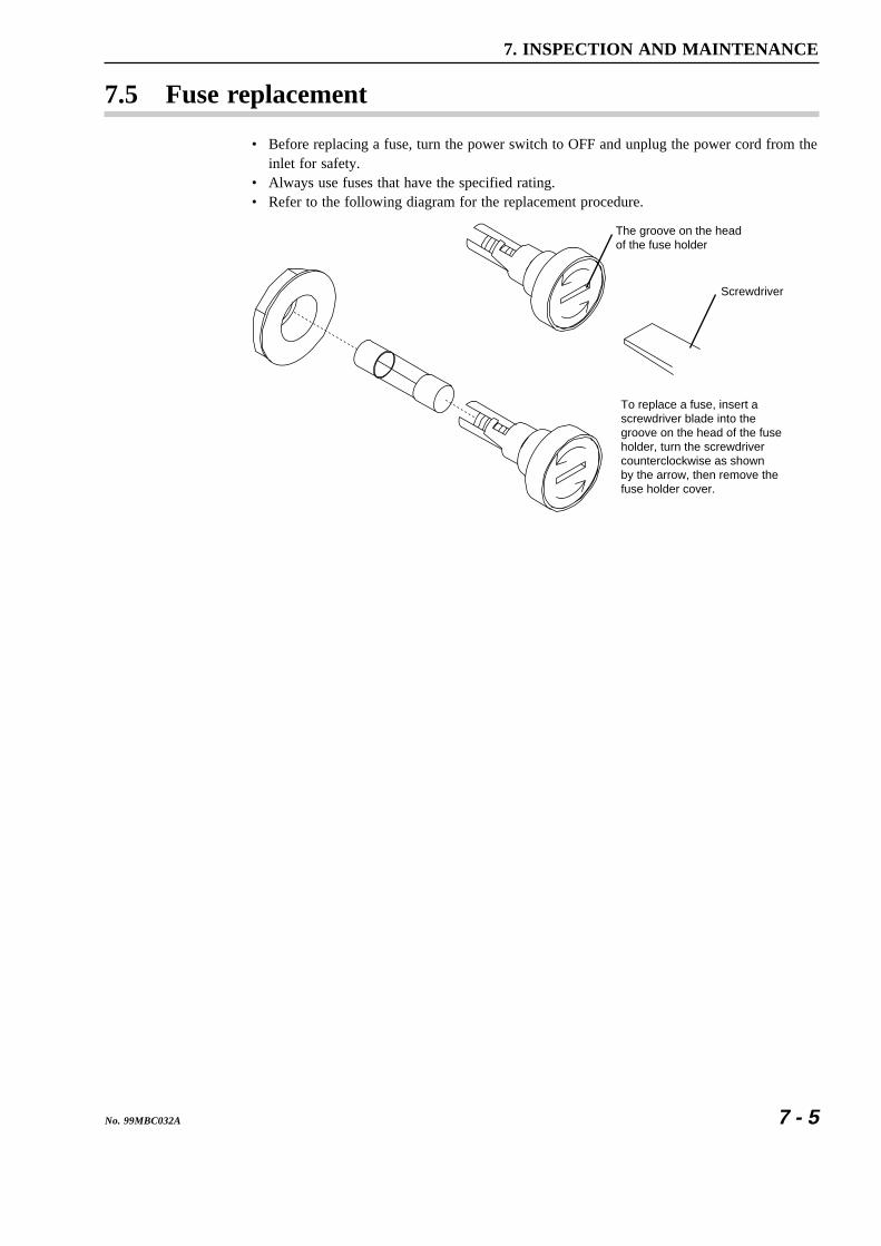
7 - 5No. 99MBC032A
7. INSPECTION AND MAINTENANCE
7.5 Fuse replacement
• Before replacing a fuse, turn the power switch to OFF and unplug the power cord from theinlet for safety.
• Always use fuses that have the specified rating.• Refer to the following diagram for the replacement procedure.
To replace a fuse, insert a screwdriver blade into the groove on the head of the fuse holder, turn the screwdriver counterclockwise as shown by the arrow, then remove the fuse holder cover.
The groove on the head of the fuse holder
Screwdriver

7 - 6 No. 99MBC032A
MEMO

8
8 - 1No. 99MBC032A
This chapter describes the specifications, supplied accessories and externalview and dimensions of the LSM-9506.
SPECIFICATIONS
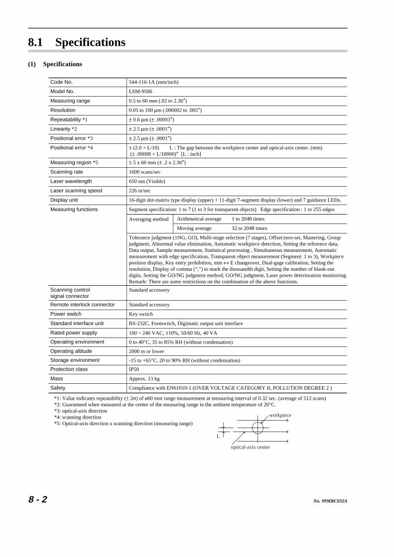
8 - 2 No. 99MBC032A
8.1 Specifications
(1) Specifications
Display unit
Laser scanning speed 226 m/sec
Laser wavelength 650 nm (Visible)
Scanning rate 1600 scans/sec
Measuring region *5 ± 5 x 60 mm (± .2 x 2.36″)
Positional error *4 ± (2.0 + L/10) L : The gap between the workpiece center and optical-axis center. (mm) (± .00008 + L/10000)″ [L : inch]
Positional error *3 ± 2.5 μm (± .0001″)
Linearity *2 ± 2.5 μm (± .0001″)
Repeatability *1 ± 0.6 μm (± .00003″)
Resolution 0.05 to 100 μm (.000002 to .005″)
Measuring range 0.5 to 60 mm (.02 to 2.36″)
Model No. LSM-9506
Code No. 544-116-1A (mm/inch)
16-digit dot-matrix type display (upper) + 11-digit 7-segment display (lower) and 7 guidance LEDs.
Measuring functions Segment specification: 1 to 7 (1 to 3 for transparent objects) Edge specification : 1 to 255 edges
Arithmetical average
Moving average
1 to 2048 times
32 to 2048 times
Averaging method
Tolerance judgment (±NG, GO), Multi-stage selection (7 stages), Offset/zero-set, Mastering, Groupjudgment, Abnormal value elimination, Automatic workpiece detection, Setting the reference data, Data output, Sample measurement, Statistical processing , Simultaneous measurement, Automaticmeasurement with edge specification, Transparent object measurement (Segment: 1 to 3), Workpiece position display, Key entry prohibition, mm ↔ E changeover, Dual-gage calibration, Setting the resolution, Display of comma (“,”) to mark the thousandth digit, Setting the number of blank-out digits, Setting the GO/NG judgment method, GO/NG judgment, Laser power deterioration monitoring.Remark: There are some restrictions on the combination of the above functions.
Power switch Key switch
Protection class IP50
Mass Approx. 13 kg
Safety Compliance with EN61010-1 (OVER VOLTAGE CATEGORY II, POLLUTION DEGREE 2 )
0 to 40°C, 35 to 85% RH (without condensation)
Standard interface unit RS-232C, Footswitch, Digimatic output unit interface
Scanning control signal connector
Standard accessory
Operating environment
100 ~ 240 VAC, ±10%, 50/60 Hz, 40 VARated power supply
2000 m or lowerOperating altitude
-15 to +65°C, 20 to 90% RH (without condensation)Storage environment
Remote interlock connector Standard accessory
*1: Value indicates repeatability (± 2σ) of ø60 mm range measurement at measuring interval of 0.32 sec. (average of 512 scans)*2: Guaranteed when measured at the center of the measuring range in the ambient temperature of 20°C.*3: optical-axis direction*4: scanning direction*5: Optical-axis direction x scanning direction (measuring range)
L
optical-axis center
workpiece

8 - 3No. 99MBC032A
8. SPECIFICATIONS
(2) Standard Accessories
.oNtraP metI ytitnauQ
drocrewoP )1etoN 1
626439 )wolleY/neerG(eriwdaelDNG )1etoN1
020CDA20 )yarG(eriwdaelDNG )1etoN
240659 )tinuyalpsidehtnodetnuomsadereviled(rotcennockcolretnietomerrofnipgnitiucric-trohS 1
839412 )straPotaS:rerutcafunam,2-JP(rotcennockcolretnietomeR 1
104CGA20 )P-0422-JP(rotcennocgnirotinomlangisnacS 1
506CGA20 )ASC,LUmorfelbaliavA()galemiT(A1esuF )2etoN1
606CGA20 )ISB,OKMESmorfelbaliavA()galemiT(A1esuF )2etoN
406CGA20 hctiwsyekrewoP 2
A230CBM99 )A611-445,A511-445rof(launaMs'resU )3etoN1
A130CBM99 )A611-445dnaA511-445roftpecxesledomllA(launaMs'resU )3etoN
.yrtnuocderevilednognidnepeD:3,2,1etoN
(3) Optional Accessories
.oNtraP metI
739639 elbactinUtuptuOcitamigiD
A006DGA20 )CAV001(1J-7004-WP+B03-414-UPD:teselbacretnirP
B006DGA20 )CAV021(1U-7004-WP+B03-414-UPD:teselbacretnirP
C006DGA20 )CAV032(1E-7004-WP+B03-414-UPD:teselbacretnirP
366322 )sllor01(repapretnirP
T971739 hctiwstooF

8 - 4 No. 99MBC032A
(4) External view and dimensions
ø3.1 (Measurement position)
12-M3
Measuring region
365(14.37)
647(25.47)
100(3.94)
100(3.94)
82(3.23)
11(.43)
10(.39)
8(.31)
213
(8.3
9) 202
(7.9
5)11 (.43
)
11 (.43
)
60(2
.36)
52(2
.05)
98(3
.86)
8(.
31)
25(.97)40
(1.57)52.5
(2.07)
172(6.77) 13.5(.53)
Unit : mm (inch)
80(3
.15)
Cab
le s
pace
:18
0(7
.07)
382(15.04)
180(7.09)
83(3.27)
97(3.82)
85(3.35)
150(5.9)
10(.39)
100(3.94)
50(1.97)
22(.87)
10.5
(.41
)15
.5(.
61)
60(2
.36)
10 (.39
)10
0(3
.94)
120
(4.7
2)

9
9 - 1No. 99MBC032A
This chapter describes the restrictions associated with the particularcombination of functions. It also describes the basic setup modes usingtables.
RESTRICTIONS ASSOCIATEDWITH THE COMBINATION OFFUNCTIONS, TABLES OFTHE BASIC SETUP MODES
9.1 Restrictions Associated with the Particular Combinationof Functions
The following restrictions exist for function combinations.
a. Restrictions on the combination of functions for single measurement are as follows:
Functionscombinations
Edgespecif-ication
Edge specification
Manualmeasure-ment
Automaticmeasure-ment
Trans-parentobjectmeasure-ment
Automaticworkpiecedetection
Abnormalvalueelimination
Samplemeasure-ment
Movingaverage
Transparent objectmeasurement
Automatic workpiecedetection
Abnormal valueelimination
Sample measurement
Group judgment
Note: "o" indicates permitted combinations, and "-" indicates combinations that are not permitted.
Manualmeasure-ment
Automaticmeasure-ment
Groupjudgment
Moving average
— —
—
—
— — —
—
—
—
—
—
—
—
—
—
—
—

9 - 2 No. 99MBC032A
b. The following restrictions are applied to the combinations of functions depending on themeasurement method:
Singlemeasurement
Simultaneousmeasurement
Automaticmeasurement
Transparent object measurement
Automatic workpiece detection
Abnormal value elimination
Group judgment
Note: “ ” indicates permitted combinations under the restrictions shown in the a) section. “-” indicates combinations that are not permitted.
—
—Manualmeasurement
Moving average
Sample measurement
—
—
—
Edge specification

9 - 3No. 99MBC032A
9. RESTRICTIONS ASSOCIATED WITH THE COMBINATION OF FUNCTIONS, TABLES OF THE BASIC SETUP MODES
9.2 List of Setup ModesTables in the following are the list of setup modes. Use these tables to check the setup data.
1. Make a check in the squares at the left of the mode number or in the setting contentcolumn that need to be set up.
2. Fill in the setup values for the underlined part.3. If these setup values are frequently changed, make copies of these forms.
9.2.1 List of basic setup modes
a: Resolution ( )
10
d. Method of average ( )
Mode No. Setup item Setup contents Default setup
B1
B2
b: Number of blank-out digits ( )
c: Mark of thousandth digit ( )
a. Output in the ready state ( )
b. Message in the event of Err-0 ( )
c. Message at the start of me asurement ( )
e. Method of GO/NG judgment ( )
a. Workpiece type ( )
B0
b. Simultaneous measurement ( )
e. Display latch timer ( )
d: Buzzer sound ( )
Note: System error alarm can not be prohibited.
c. Method of segment designation ( )
: No blank-out/ : 1 digit/ : 2 digits
: Does not output the GO/NG judgment : Output the GO/NG judgment
: Displays “Err-0”. : Displays “0”.
: Judges with the lower limit and upper limit : Judges by multi-stage selection : Judges with the target value + tolerance f : Method of using the target value and reference value ( ) : Does not copy the target value on the reference value : Copies the target value on the reference value
: Displays “-------”. : Displays the previous data
: Arithmetic average / : Moving average
: 0/ : 1/ : 2/ : 3/ : 4/ : 5/ : 6/ : 7
: No mark/ : Mark
sec.
: Sounds at any event. : Sounds when key input is made (indicating acceptance or operation error). : Sounds when a NG measurement results. : Does not sound except a system error alarm.
: Opaque object : Transparent object
: Single measurement : Simultaneous measurement
: Segment specification : Edge specification
( )

9 - 4 No. 99MBC032A
Mode No. Setup item Setup contents Default setup
B3 a. Abnormal value elimination ( )
b. Automatic workpiece detection ( )
B4 a. RS-232C port ( )
b. Baud rate ( )
c. Data bits ( )
d. Parity check ( )
e. Delimiter ( )
f. line control ( )
Reserved
a. Use of DCU ( )
d. Group judgment ( )
: Does not use / : Use.
: Does not use. : OD detection / : Position detection c: Number of scans : 16 times / : 1 time
: Uses for communication with PC : Uses as a printer port (GP-IB is also available) : Does not use. (GP-IB is also available)
/ / / /
: 8 bits/ : 7 bits
: Does not use. : Odd parity : Even parity
: CR + LF / : CR / : LF
: Does not use. : Uses.
: Does not use. : Uses. e. Setting the group judgment result output ( ) : Does not output. : Outputs.
: Does not use. : Uses.
B5
B6
9.2.2 List of calibration functions
Mode No. Setup item Setup range Default setting
: HIGH CAL gage =
= : LOW CAL gage
HIGH CAL
LOW CAL
Setup contents
Max.7 digits in thepositive direction only.
Max.7 digits in thepositive direction only.
Cancel (0)
Free (0)
CAL
9.2.3 Reading in the amount of light
Mode No. Setup range Default setting
: Automatically performs light amount detection. : Reading in the light amount.
Setup contents
—Light amount detection

9 - 5No. 99MBC032A
9. RESTRICTIONS ASSOCIATED WITH THE COMBINATION OF FUNCTIONS, TABLES OF THE BASIC SETUP MODES
9.2.4 List of function setup modes
Program No.: /
Mode No. Setup item Setup range Default setting
: Segment No. =
F1
F2
F4
F3
Segmentspecification*
Setup contents
Edge specification* : Use of automatic measurement : Manual measurement
: Automatic pitch measurement
: Automatic diameter measurement
: Automatic gap measurement : Start edge : Finish edge =
Measurementinterval
: Number of scans for averaging Arithmetic average (Guidance: ) Moving average (Guidance: )
=
==
==
======
===
=
===
==
=
===
(abnormal valueelimination)*
: Lower abnormal limit : Upper abnormal limit
GO/NG judgment* : Lower limit value : Upper limit value
Sign + max. 7 digitsSign + max. 7 digits
Sign + max. 7 digitsSign + max. 7 digitsSign + max. 7 digitsSign + max. 7 digitsSign + max. 7 digitsSign + max. 7 digits
: Target value : Lower tolerance limit : Upper tolerance limit
Reference value* : Reference value
Offset : Offset value : Direction : Mastering value
Max. 7 positions 1
1 to 2542 to 255
—
1 to 204832 to 2048
Sign + max. 7 digitsSign + max. 7 digits
Sign + max. 7 digitsSign + max. 7 digitsSign + max. 7 digits
Sign + max. 7 digits
Sign + max. 7 digits0, 1Sign + max. 7 digits
•
•
•
•
1 to 2 at NONE
2 to 5 at PIT
2 to 3 at DIA
3 to 4 at GAP
512512
Free (0)
Free (0)
F5 Data outputcondition
: Data output condition : Periodic data output timer
0 to 90 to 999 sec
Free (0)
Free (0)
F6 Samplemeasurement
: Number of samples : Statistical item : Mean / : Maximum value / :Minimum value / : Range
0 to 999
—
Free (1)
F7 Automaticworkpiecedetection*(Position detectionshould be made inthe positivedirection only.)
: Number of measurement times = : Invalidation period ms : Lower detection limit : Upper detection limit
0 to 9990 to 9999Sign + max. 7 digitsSign + max. 7 digits
Free (0)
F8 Group judgment* : Group size subject to judgment = : Statistical item applied for group judgment : Mean : Maximum value : Minimum value : Range : Group lower limit = : Group upper limit =
0 to 99
—
Sign + max. 7 digitsSign + max. 7 digits
Free (0)
Free (0)
Free (0)
Free (0) : Multi-limit selection 1 : Multi-limit selection 2 : Multi-limit selection 3 : Multi-limit selection 4 : Multi-limit selection 5 : Multi-limit selection 6
F0
* Varies depending on the basic set up.

9 - 6 No. 99MBC032A
MEMO
SERVICE NETWORK
Mitutoyo America Corporation Illinois Repair Service 958 Corporate Blvd., Aurora, IL. 60504, U.S.A. TEL: (630)820-3334 FAX: (630)820-2530 Michigan Repair Service45001 Five Mile Rd., Plymouth, MI 48170, U.S.A. TEL: (734)459-2810 FAX: (734)459-0455 Los Angeles Repair Service 16925 East Gale Ave., City of Industry, CA 91745, U.S.A. TEL: (626)961-9661 FAX: (626)333-8019 for Advanced Technical Support Service Indianapolis Metrology Center TEL: (317)577-6070 FAX: (317)577-6080 Boston Metrology Center TEL: (978)692-7474 FAX: (978)692-9729 Charlotte Metrology Center TEL: (704)875-8332 FAX: (704)875-9273
Mitutoyo Canada Inc.2121 Meadowvale Blvd., Mississauga, Ont. L5N 5N1, CANADATEL: (905)821-1261 to 3 FAX: (905)821-4968
Mitutoyo Sul Americana Ltda.AV. João Carlos da Silva Borges, 1240, CEP 04726-002 Santo Amaro P.O. Box 4255 São Paulo, BRASIL TEL: (011)5643-0000 FAX: (011)5641-3722Argentina Branch Av. Mitre 891/899 -C.P.(B1603CQI) Vicente Lopez-Pcia. Buenos Aires, ARGENTINA TEL: (011)4730-1433 FAX: (011)4730-1411
Mitutoyo Mexicana S.A. de C.V. Prol. Ind. Electrica #15 Col. Parq. Ind. Naucalpan C.P.53370, Naucalpan, Edo. de Mexico, MEXICO TEL: 05-312-5612 FAX: 05-312-3380
Mitutoyo Meßgeräte GmbH Borsigstr. 8-10, 41469 Neuss F.R. GERMANY TEL: (02137)102-0 FAX: (02137)8685
Mitutoyo Polska Sp.z o.o. ul. Minska, nr54-56, Wroclaw, POLAND TEL: (0048)71-3548350 FAX: (0048)71-3548355
Mitutoyo Nederland B.V.Postbus 550, Landjuweel 35, 3905 PE Veenendaal, NETHERLANDSTEL: 0318-534911 FAX: 0318-516568
Mitutoyo Scandinavia A.B.Box 712, Släntvägen 6, 194 27 Upplands-Väsby, SWEDEN TEL:(07)6092135 FAX: (07)6092410
Mitutoyo Belgium N.V.Hogenakkerhoekstraat 8, 9150 Kruibeke, BELGIUM TEL: 03-254 04 04 FAX: 03-254 04 05
Mitutoyo France S.A.R.L. 123, rue de la Belle Etoile, B.P. 50267-Z.I. Paris Nord II 95957 Roissy CDG Cedex, FRANCE TEL: (01)49 38 35 00 FAX: (01)49 38 35 35 Mitutoyo France S.A.R.L., Agence de Lyon TEL: (04) 78 26 98 07 FAX: (04) 72 37 16 23 Mitutoyo France S.A.R.L., Agence de Strasbourg TEL: (03) 88 67 85 77 FAX: (03) 88 67 85 79
Mitutoyo Italiana S.R.L. Corso Europa No.7, 20020 Lainate, Milano, ITALY TEL: (02)935781 FAX: (02)9373290
Mitutoyo Schweiz AGSteinackerstrasse 35, 8902 Urdorf-Zürich, SWITZERLAND TEL: (01)7361150 FAX: (01)7361151
Mitutoyo (U.K.) Ltd. Joule Road, West Point Business Park, Andover, Hampshire SP10 3UX UNITED KINGDOM TEL: (01264)353123 FAX: (01264)354883
Mitutoyo Asia Pacific Pte. Ltd. Regional Headquarters 24 Kallang Avenue, Mitutoyo Building, SINGAPORE 339415 TEL: 6294-2211 FAX: 6299-6666Mitutoyo (Malaysia) Sdn. Bhd.Suite G.2 Ground Floor, 2A Jalan 243, Section 51A 46100 Petaling Jaya, Selangor Darul Ehsan, MALAYSIA TEL: 03-7845-9318 FAX: 03-7845-9346 Mitutoyo Thailand Co.,Ltd.No.668/3, Moo7 Chaengwattana Rd. Anusaowaree, Bangkaen, Bangkok 10220, THAILAND TEL: (02)521-6130 to 5 FAX: (02)521-6136 Representative Office Indonesia: TEL: 021-526-0737 to 8 FAX: 021-526-0736 Vietnam (Ho Chi Minh City): TEL: (08)910-0485 to 6 FAX: (08)910-0487
Vietnam (Hanoi): TEL: (04)934-7098 FAX: (04)934-7072 Philippines: TEL: (02)842-9305 FAX: (02)842-9307
Mitutoyo South Asia Pvt. Ltd.C-122, Okhla Industrial Area, Phase-�,New Delhi-110 020, INDIA TEL: 011-6372091 to 2 FAX: 011-6372636
Mitutoyo Taiwan Co.,Ltd.5th FL. No.123, Wu Kung First Road, Wu Ku Industrial Park, Taipei Hsien, TAIWAN, R.O.C. TEL: (02)2299-5266 FAX: (02)2299-2358
Mitutoyo Korea Corporation KOCOM Building 2F, #260-7, Yeom Chang-Dong, Kang Seo-Gu, Seoul, 157-040, KOREA TEL: (02)3661-5546 to 7 FAX: (02)3661-5548
Mitutoyo (Beijing) Liaison Office#1011, Beijing Fortune Bldg., No.5 Dong Sanhuan Bei-Lu Chaoyang District, Beijing 100004 P.R.CHINA TEL: 010-65908505 FAX: 010-65908507
Mitutoyo Measuring Instruments Co., Ltd. Shanghai:Room B 11/F, Nextage Business Center No.1111 Pudong South Road, Pudong New District, Shanghai, 200120, P.R. CHINA TEL: 021-5830-7718 FAX: 021-5830-7717 Suzhou: 46, Bai Yu Street, Suzhou, P.R. CHINA TEL: 0512-62522660 FAX: 0512-62522580

Mitutoyo Corporation20-1, Sakado 1-chome, Takatsu-ku, Kawasaki, Kanagawa 213-0012, JapanCable: MITUTOYO Kawasaki Telex: 3842-118Phone: (044)813-8230 Fax: (044)813-8231
Printed in JapanCQAONE202022