lt230 series digital indicating controller · inst.№ ine-307b lt230 series digital indicating...
TRANSCRIPT
INST. INE-307B
LT230 series Digital Indicating Controller
Instruction Manual
Read this instruction manual carefully to use your controller safely and avoid troubles. If your controller is with optional communications interface, read the separate instruction manual (INE-315), too.
Checking of Model No. Check Model No. of your controller and its specifications.
To agents or distributors
Make sure to pass this instruction manual to final customers.
To our valuable customers
Keep this instruction manual until disposing of your controller.
Model code 1 Front view Accessories/parts 1
Notes on safety 1 1. Installation to a panel 1 2. Before wirings 2 3. Terminal arrangement 2 4. Troubleshooting/Maintenance 2
5. Specifications 2 6. Parameter directory 3 7. List of parameters 3 8. Description of parameters 3 9. Setting of parameters 4 10. Operation 4 11. Event mode and output 4
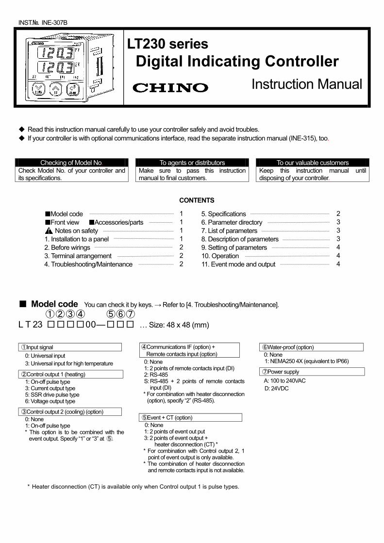
Model code You can check it by keys. → Refer to [4. Troubleshooting/Maintenance]. ①②③④ ⑤⑥⑦ L T 23 00― … Size: 48 x 48 (mm) ①Input signal
0: Universal input 3: Universal input for high temperature
②Control output 1 (heating) 1: On-off pulse type 3: Current output type 5: SSR drive pulse type 6: Voltage output type
③Control output 2 (cooling) (option) 0: None 1: On-off pulse type * This option is to be combined with the
event output. Specify “1” or “3” at ⑤.
④Communications IF (option) + Remote contacts input (option)
0: None 1: 2 points of remote contacts input (DI) 2: RS-485 S: RS-485 + 2 points of remote contacts
input (DI) * For combination with heater disconnection
(option), specify “2” (RS-485).
⑤Event + CT (option) 0: None 1: 2 points of event out put
3: 2 points of event output + heater disconnection (CT) *
* For combination with Control output 2, 1 point of event output is only available.
* The combination of heater disconnection and remote contacts input is not available.
⑥Water-proof (option) 0: None 1: NEMA250 4X (equivalent to IP66)
⑦Power supply A: 100 to 240VAC D: 24VDC
* Heater disconnection (CT) is available only when Control output 1 is pulse types.
CONTENTS
32-8, KUMANO-CHO, ITABASHI-KU, TOKYO 173-8632
Telephone : + 81-3-3956-2171 Facsimi le : + 81-3-3956-0915 E - m a i l : [email protected] W e b s i t e : http://www.chino.co.jp/
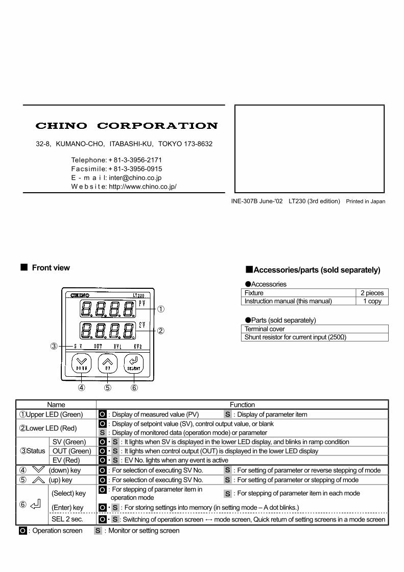
Front view
Accessories/parts (sold separately) Accessories Fixture 2 pieces Instruction manual (this manual) 1 copy Parts (sold separately) Terminal cover Shunt resistor for current input (250Ω)
Name Function ①Upper LED (Green) :Display of measured value (PV) :Display of parameter item
②Lower LED (Red) :Display of setpoint value (SV), control output value, or blank :Display of monitored data (operation mode) or parameter
SV (Green) ・ :It lights when SV is displayed in the lower LED display, and blinks in ramp condition OUT (Green) ・ :It lights when control output (OUT) is displayed in the lower LED display ③Status EV (Red) ・ :EV No. lights when any event is active
④ (down) key :For selection of executing SV No. :For setting of parameter or reverse stepping of mode ⑤ (up) key :For selection of executing SV No. :For setting of parameter or stepping of mode
(Select) key :For stepping of parameter item in operation mode :For stepping of parameter item in each mode
(Enter) key ・ :For storing settings into memory (in setting mode – A dot blinks.) ⑥
SEL 2 sec. ・ :Switching of operation screen ↔ mode screen, Quick return of setting screens in a mode screen :Operation screen :Monitor or setting screen
INE-307B June-'02 LT230 (3rd edition) Printed in Japan
O O
O O O O O
S S S
S
S
S S
O S
④ ⑤ ⑥
③
②
①
O S
O
O
S
S
1
Notes on safety
1. Precondition for use Your controller is designed for installation in indoor panels. International safety standards
∙ Front panel (option)
NEMA250 4X (equivalent to IP66 under IEC529) Not available in closed installation
∙ CE
EMC: EN61326+A1 * Safety: EN61010-1+A2 Overvoltage category II, Pollution degree 2
∙ UL standards UL3121-1 ∙ CSA standards (C-UL)
CSA C22.2 No. 1010
* The displayed value and the output value equivalent to maximum ±10% or ±2mV may vary under the test environment of EMC directive.
2. Symbols used in your controller ∙ Used in your controller
Label Name Explanation Alert
symbol mark
Indicates the locations where there is a risk of electrical shock or injury.
∙ Used in this manual
Indicates the locations where there is a risk of electrical shock or injury.
Indicates the items that your controller may result in insufficient functioning.
Warning/Caution 1. Confirmation of power voltage and wirings
Confirm the power voltage and wirings before turning on the power supply.
2. Termination of wirings Use crimping terminals with insulation sleeve.
3. Power switch For the power supply, prepare a switch and an overcurrent protection device within 3m of your controller.
4. Safety measures for output Control output or event output may not be correct due to wrong operation, malfunction, sensor abnormal or other factors. Prepare safety measures at final products side if required.
5. Prohibition of repair and modification To avoid electrical shock, fire and malfunction, other personnel than the service personnel authorized by CHINO are prohibited to repair, modify or disassemble your controller.
6. Turning off the power supply When you feel or find abnormal conditions such as smelling or heating, turn off the power supply and contact your agent of CHINO Corporation.
Request for ensuring against risks 1. Environment
Make sure not to use your controllers in ・ places containing corrosive gas (ex. sulfuric gas, etc.),
powder or dust, ・places containing flammable or explosive gas, ・places flooded or covered with oil, ・ places subject to significant change of temperature and
strong wind ・places where is significantly influenced by vibration and shock ・places subject to direct sunlight and dew condensation.
2. Unused terminals Make sure not to wire to unused terminals.
3. Inductive noise ・Make sure to separate all wirings to your controller from
power line with high voltage or high current. ・Install your controller apart from equipment generating
strong magnetic field, electrical field or high frequency. 4. Ventilation
Make sure not to block the ventilation openings to ensure the heat dissipating space for your controller.
5. Cleaning When cleaning is required, make sure not to use chemicals (ex. thinner, benzene, etc.) affecting molded parts. Use alcohol available in markets.
6. Safety measures at final products side ・ To ensure safety in the event of malfunction of your
controller, prepare separate safety measures. ・ Prepare an enclosure for protection against fire when
installing your controller. ・Prepare safety measures to prevent contact with
terminals.
Caution
Note
70
70 45
+0.6
0
+0.6 0
45 +0.6
0
45 +0.6 0
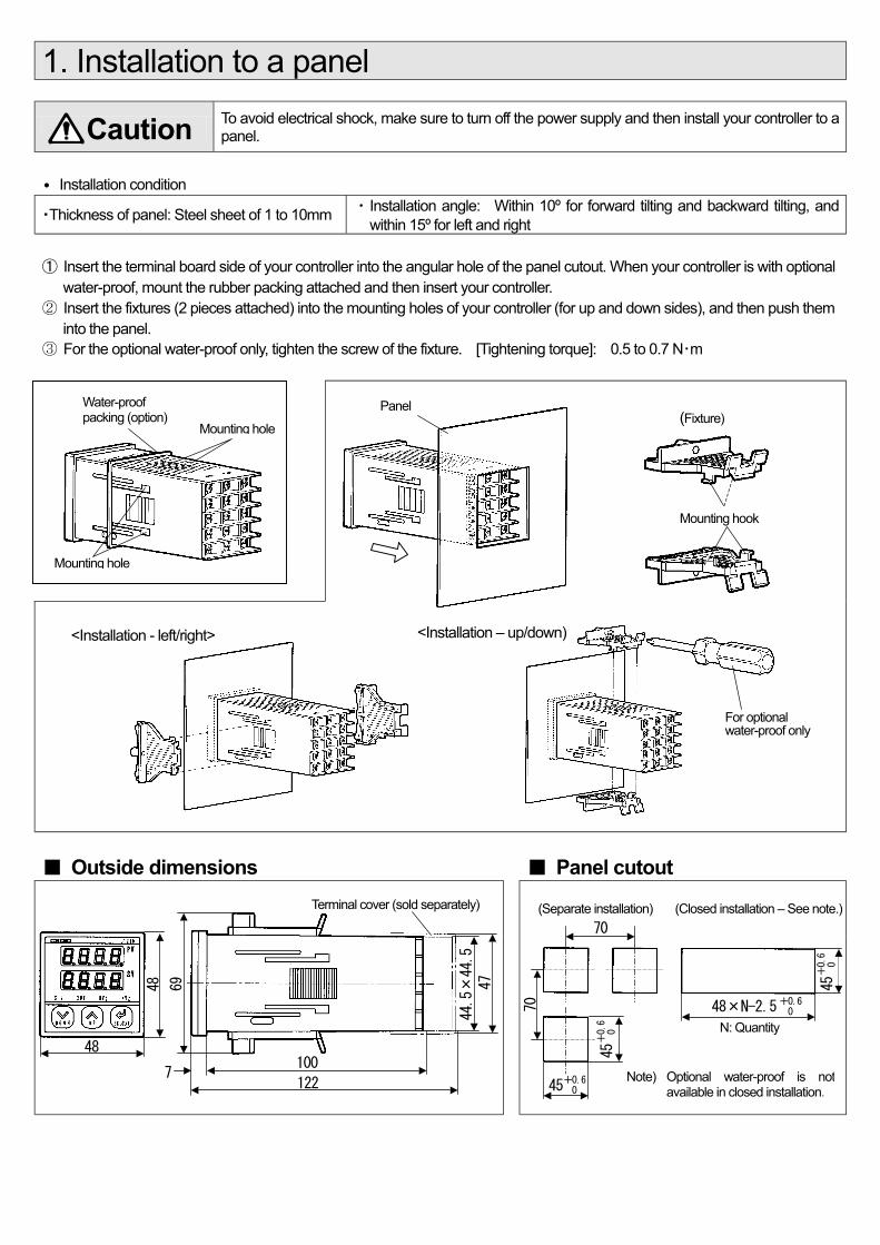
1. Installation to a panel
To avoid electrical shock, make sure to turn off the power supply and then install your controller to a panel.
∙ Installation condition
・Thickness of panel: Steel sheet of 1 to 10mm ・ Installation angle: Within 10º for forward tilting and backward tilting, and within 15º for left and right
① Insert the terminal board side of your controller into the angular hole of the panel cutout. When your controller is with optional water-proof, mount the rubber packing attached and then insert your controller.
② Insert the fixtures (2 pieces attached) into the mounting holes of your controller (for up and down sides), and then push them into the panel.
③ For the optional water-proof only, tighten the screw of the fixture. [Tightening torque]: 0.5 to 0.7 N・m
Outside dimensions Panel cutout
(Separate installation) (Closed installation – See note.)
Caution
<Installation - left/right> <Installation – up/down)
48
48
69
44.5×44.5
47
100
122 7
Water-proof packing (option)
Mounting hole
Mounting hole
Panel (Fixture)
Mounting hook
For optional water-proof only
Terminal cover (sold separately)
48×N-2.5
N: Quantity
Note) Optional water-proof is notavailable in closed installation.
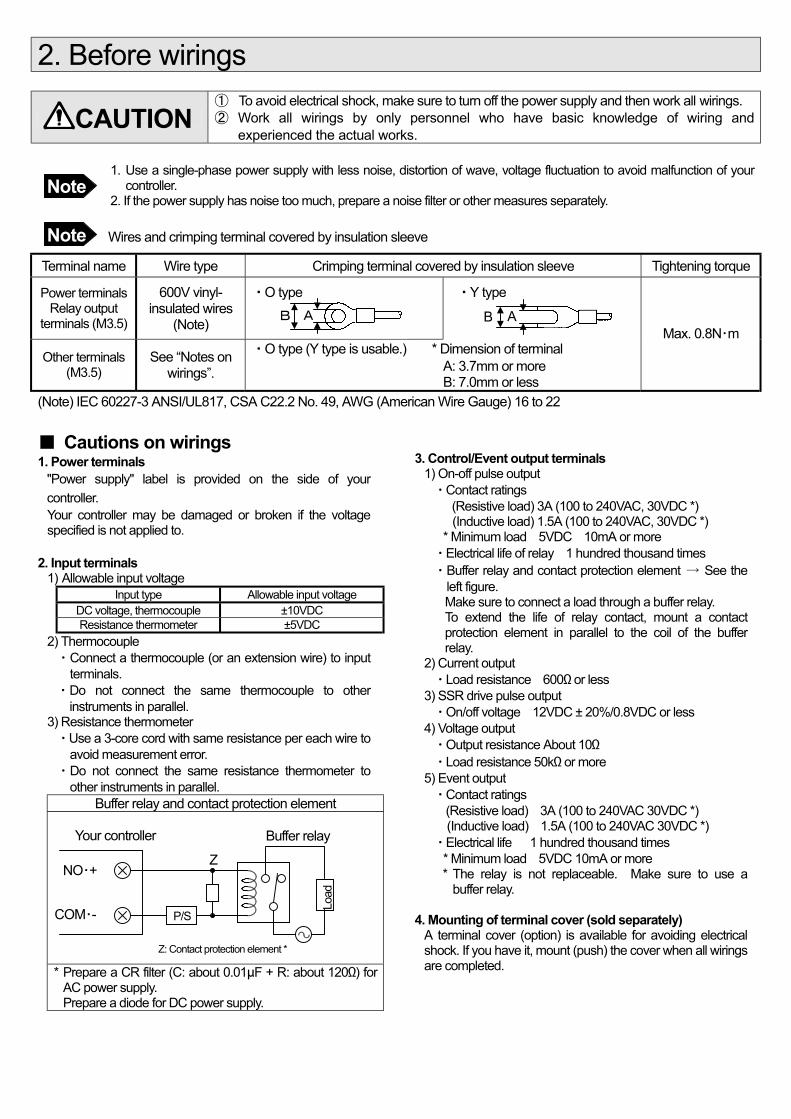
2. Before wirings
① To avoid electrical shock, make sure to turn off the power supply and then work all wirings. ② Work all wirings by only personnel who have basic knowledge of wiring and experienced the actual works.
1. Use a single-phase power supply with less noise, distortion of wave, voltage fluctuation to avoid malfunction of your controller. 2. If the power supply has noise too much, prepare a noise filter or other measures separately.
Wires and crimping terminal covered by insulation sleeve
Terminal name Wire type Crimping terminal covered by insulation sleeve Tightening torque
Power terminals Relay output
terminals (M3.5)
600V vinyl- insulated wires
(Note)
・O type
・Y type
Other terminals (M3.5)
See “Notes on wirings”.
・O type (Y type is usable.) * Dimension of terminal A: 3.7mm or more B: 7.0mm or less
Max. 0.8N・m
(Note) IEC 60227-3 ANSI/UL817, CSA C22.2 No. 49, AWG (American Wire Gauge) 16 to 22
Cautions on wirings 1. Power terminals
"Power supply" label is provided on the side of your controller. Your controller may be damaged or broken if the voltage specified is not applied to.
2. Input terminals
1) Allowable input voltage Input type Allowable input voltage
DC voltage, thermocouple ±10VDC Resistance thermometer ±5VDC
2) Thermocouple ・ Connect a thermocouple (or an extension wire) to input
terminals. ・ Do not connect the same thermocouple to other
instruments in parallel. 3) Resistance thermometer ・Use a 3-core cord with same resistance per each wire to
avoid measurement error. ・ Do not connect the same resistance thermometer to
other instruments in parallel. Buffer relay and contact protection element
* Prepare a CR filter (C: about 0.01µF + R: about 120Ω) for AC power supply. Prepare a diode for DC power supply.
3. Control/Event output terminals
1) On-off pulse output ・Contact ratings (Resistive load) 3A (100 to 240VAC, 30VDC *) (Inductive load) 1.5A (100 to 240VAC, 30VDC *)
* Minimum load 5VDC 10mA or more ・Electrical life of relay 1 hundred thousand times ・ Buffer relay and contact protection element → See the
left figure. Make sure to connect a load through a buffer relay. To extend the life of relay contact, mount a contact protection element in parallel to the coil of the buffer relay.
2) Current output ・Load resistance 600Ω or less
3) SSR drive pulse output ・On/off voltage 12VDC ± 20%/0.8VDC or less
4) Voltage output ・Output resistance About 10Ω ・Load resistance 50kΩ or more
5) Event output ・Contact ratings (Resistive load) 3A (100 to 240VAC 30VDC *)
(Inductive load) 1.5A (100 to 240VAC 30VDC *) ・Electrical life 1 hundred thousand times
* Minimum load 5VDC 10mA or more * The relay is not replaceable. Make sure to use a
buffer relay.
4. Mounting of terminal cover (sold separately) A terminal cover (option) is available for avoiding electrical shock. If you have it, mount (push) the cover when all wirings are completed.
CAUTION
Note
Note
Z: Contact protection element *
NO・+
COM・- Load
Z
P/S
Your controller Buffer relay
A B A B
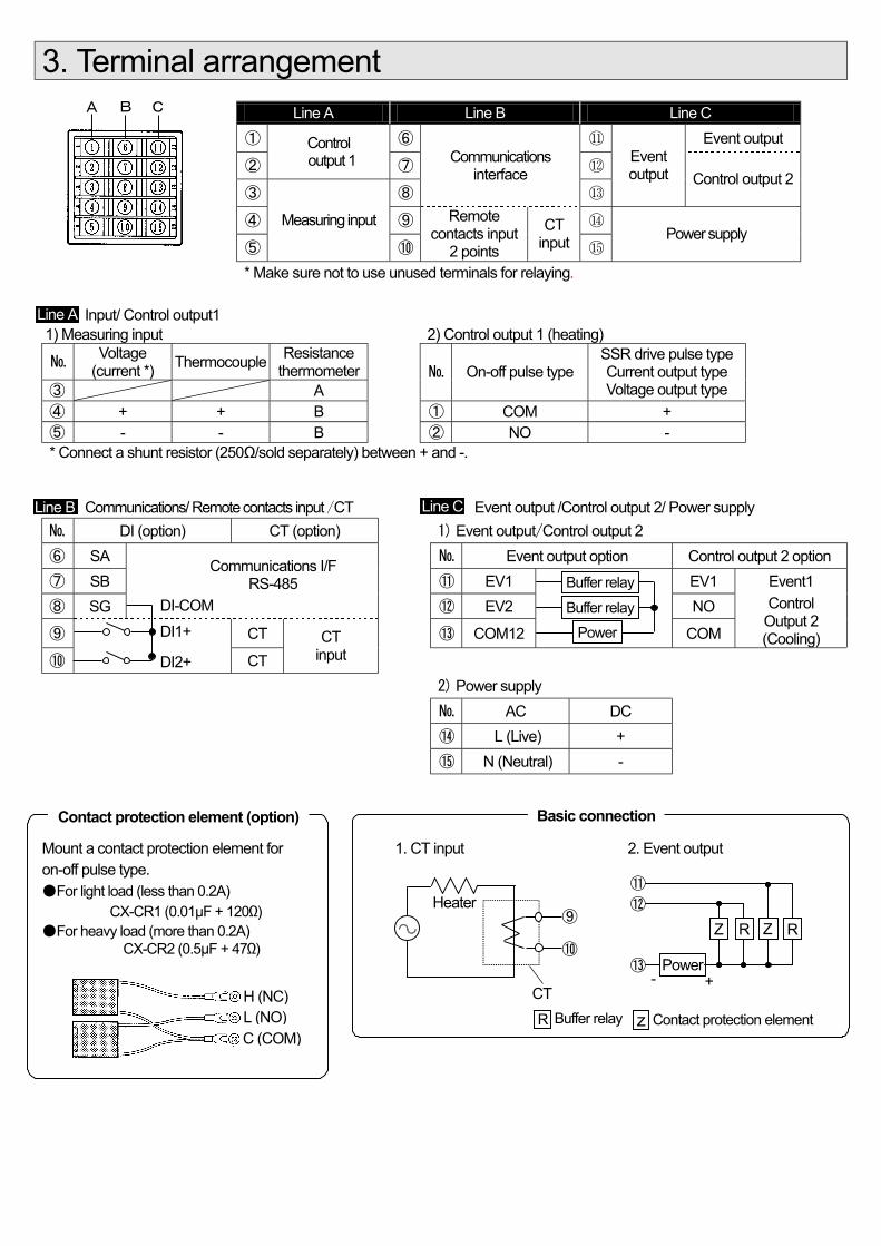
3. Terminal arrangement
Line A Line B Line C ① ⑥ ⑪ Event output
② Control
output 1 ⑦ ⑫
③ ⑧
Communications interface
⑬
Event output Control output 2
④ ⑨ ⑭
⑤ Measuring input
⑩
Remote contacts input
2 points CT
input ⑮ Power supply
* Make sure not to use unused terminals for relaying.
Input/ Control output1 1) Measuring input 2) Control output 1 (heating)
Voltage
(current *) Thermocouple Resistance thermometer
③ A On-off pulse type
SSR drive pulse type Current output type Voltage output type
④ + + B ① COM + ⑤ - - B ② NO - * Connect a shunt resistor (250Ω/sold separately) between + and -.
Communications/ Remote contacts input /CT Event output /Control output 2/ Power supply DI (option) CT (option) 1) Event output/Control output 2 ⑥ SA Event output option Control output 2 option ⑦ SB
Communications I/F RS-485 ⑪ EV1 EV1 Event1
⑧ SG ⑫ EV2 NO
⑨ CT ⑬ COM12
COM
Control Output 2 (Cooling)
⑩
CT CT
input
2) Power supply
AC DC
⑭ L (Live) +
⑮ N (Neutral) -
Mount a contact protection element for on-off pulse type. For light load (less than 0.2A)
CX-CR1 (0.01µF + 120Ω) For heavy load (more than 0.2A) CX-CR2 (0.5µF + 47Ω)
1. CT input 2. Event output
⑪ ⑫ ⑬
Z
Power -
R Z R
+
Heater ⑨ ⑩
CT
A B C
Buffer relay
H (NC)
C (COM) L (NO)
Line A
Line B Line C
DI2+
DI1+ DI-COM
Power
Contact protection element (option) Basic connection
R Buffer relay z Contact protection element
Buffer relay
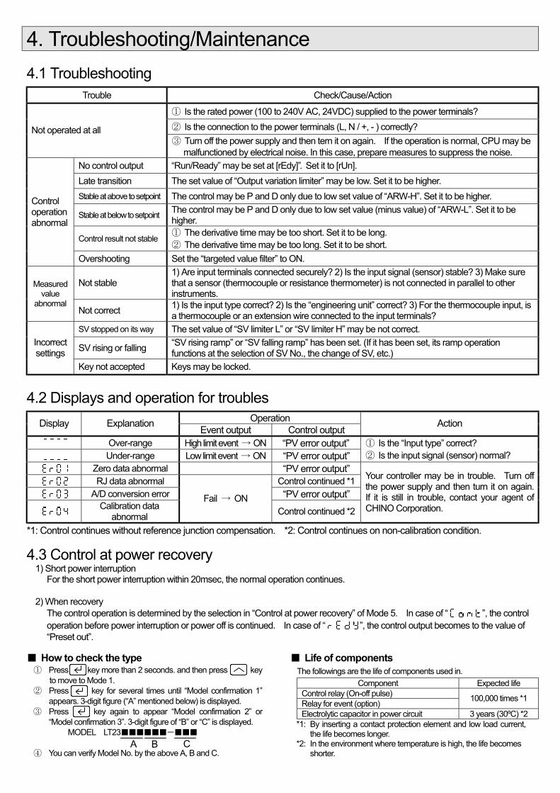
4. Troubleshooting/Maintenance
4.1 Troubleshooting Trouble Check/Cause/Action
① Is the rated power (100 to 240V AC, 24VDC) supplied to the power terminals? ② Is the connection to the power terminals (L, N / +, - ) correctly? Not operated at all ③ Turn off the power supply and then tern it on again. If the operation is normal, CPU may be
malfunctioned by electrical noise. In this case, prepare measures to suppress the noise. No control output “Run/Ready” may be set at [rEdy]”. Set it to [rUn]. Late transition The set value of “Output variation limiter” may be low. Set it to be higher. Stable at above to setpoint The control may be P and D only due to low set value of “ARW-H”. Set it to be higher.
Stable at below to setpoint The control may be P and D only due to low set value (minus value) of “ARW-L”. Set it to be higher.
Control result not stable ① The derivative time may be too short. Set it to be long. ② The derivative time may be too long. Set it to be short.
Control operation abnormal
Overshooting Set the “targeted value filter” to ON.
Not stable 1) Are input terminals connected securely? 2) Is the input signal (sensor) stable? 3) Make sure that a sensor (thermocouple or resistance thermometer) is not connected in parallel to other instruments.
Measured value
abnormal Not correct 1) Is the input type correct? 2) Is the “engineering unit” correct? 3) For the thermocouple input, is
a thermocouple or an extension wire connected to the input terminals? SV stopped on its way The set value of “SV limiter L” or “SV limiter H” may be not correct.
SV rising or falling “SV rising ramp” or “SV falling ramp” has been set. (If it has been set, its ramp operation functions at the selection of SV No., the change of SV, etc.)
Incorrect settings
Key not accepted Keys may be locked.
4.2 Displays and operation for troubles Operation Display Explanation Event output Control output Action
Over-range High limit event → ON “PV error output” Under-range Low limit event → ON “PV error output”
① Is the “Input type” correct? ② Is the input signal (sensor) normal?
Zero data abnormal “PV error output” RJ data abnormal Control continued *1 A/D conversion error “PV error output”
Calibration data
abnormal
Fail → ON Control continued *2
Your controller may be in trouble. Turn off the power supply and then turn it on again. If it is still in trouble, contact your agent of CHINO Corporation.
*1: Control continues without reference junction compensation. *2: Control continues on non-calibration condition.
4.3 Control at power recovery 1) Short power interruption
For the short power interruption within 20msec, the normal operation continues.
2) When recovery The control operation is determined by the selection in “Control at power recovery” of Mode 5. In case of “ ”, the control operation before power interruption or power off is continued. In case of “ ”, the control output becomes to the value of “Preset out”.
How to check the type ① Press key more than 2 seconds. and then press key
to move to Mode 1. ② Press key for several times until “Model confirmation 1”
appears. 3-digit figure (“A” mentioned below) is displayed. ③ Press key again to appear “Model confirmation 2” or
“Model confirmation 3”. 3-digit figure of “B” or “C” is displayed. MODEL LT23- ④ You can verify Model No. by the above A, B and C.
Life of components The followings are the life of components used in.
Component Expected life Control relay (On-off pulse) Relay for event (option) 100,000 times *1
Electrolytic capacitor in power circuit 3 years (30ºC) *2 *1: By inserting a contact protection element and low load current,
the life becomes longer. *2: In the environment where temperature is high, the life becomes
shorter. A B C
2
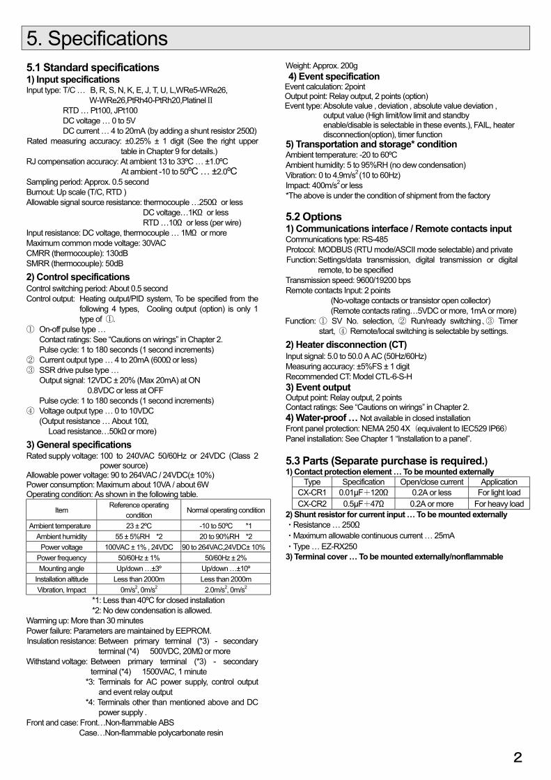
5. Specifications 5.1 Standard specifications 1) Input specifications Input type: T/C … B, R, S, N, K, E, J, T, U, L,WRe5-WRe26,
W-WRe26,PtRh40-PtRh20,PlatinelⅡ RTD … Pt100, JPt100 DC voltage … 0 to 5V DC current … 4 to 20mA (by adding a shunt resistor 250Ω) Rated measuring accuracy: ±0.25% ± 1 digit (See the right upper
table in Chapter 9 for details.) RJ compensation accuracy: At ambient 13 to 33ºC … ±1.0ºC At ambient -10 to 50ºC … ±2.0ºC Sampling period: Approx. 0.5 second Burnout: Up scale (T/C, RTD ) Allowable signal source resistance: thermocouple …250Ω or less DC voltage…1KΩ or less RTD …10Ω or less (per wire) Input resistance: DC voltage, thermocouple … 1MΩ or more Maximum common mode voltage: 30VAC CMRR (thermocouple): 130dB SMRR (thermocouple): 50dB 2) Control specifications Control switching period: About 0.5 second Control output: Heating output/PID system, To be specified from the
following 4 types, Cooling output (option) is only 1 type of ①.
① On-off pulse type … Contact ratings: See “Cautions on wirings” in Chapter 2. Pulse cycle: 1 to 180 seconds (1 second increments)
② Current output type … 4 to 20mA (600Ω or less) ③ SSR drive pulse type …
Output signal: 12VDC ± 20% (Max 20mA) at ON 0.8VDC or less at OFF
Pulse cycle: 1 to 180 seconds (1 second increments) ④ Voltage output type … 0 to 10VDC (Output resistance … About 10Ω, Load resistance…50kΩ or more) 3) General specifications Rated supply voltage: 100 to 240VAC 50/60Hz or 24VDC (Class 2
power source) Allowable power voltage: 90 to 264VAC / 24VDC(± 10%) Power consumption: Maximum about 10VA / about 6W Operating condition: As shown in the following table.
Item Reference operating
condition Normal operating condition
Ambient temperature 23 ± 2ºC -10 to 50ºC *1 Ambient humidity 55 ± 5%RH *2 20 to 90%RH *2
Power voltage 100VAC ± 1% , 24VDC 90 to 264VAC,24VDC± 10% Power frequency 50/60Hz ± 1% 50/60Hz ± 2% Mounting angle Up/down …±3º Up/down …±10º
Installation altitude Less than 2000m Less than 2000m Vibration, Impact 0m/s2, 0m/s2 2.0m/s2, 0m/s2
*1: Less than 40ºC for closed installation *2: No dew condensation is allowed.
Warming up: More than 30 minutes Power failure: Parameters are maintained by EEPROM. Insulation resistance: Between primary terminal (*3) - secondary
terminal (*4) 500VDC, 20MΩ or more Withstand voltage: Between primary terminal (*3) - secondary
terminal (*4) 1500VAC, 1 minute *3: Terminals for AC power supply, control output
and event relay output *4: Terminals other than mentioned above and DC
power supply . Front and case: Front…Non-flammable ABS
Case…Non-flammable polycarbonate resin
Weight: Approx. 200g 4) Event specification Event calculation: 2point Output point: Relay output, 2 points (option) Event type: Absolute value , deviation , absolute value deviation ,
output value (High limit/low limit and standby enable/disable is selectable in these events.), FAIL, heater disconnection(option), timer function
5) Transportation and storage* condition Ambient temperature: -20 to 60ºC Ambient humidity: 5 to 95%RH (no dew condensation) Vibration: 0 to 4.9m/s2 (10 to 60Hz) Impact: 400m/s2 or less *The above is under the condition of shipment from the factory 5.2 Options 1) Communications interface / Remote contacts input Communications type: RS-485 Protocol: MODBUS (RTU mode/ASCII mode selectable) and private Function: Settings/data transmission, digital transmission or digital
remote, to be specified Transmission speed: 9600/19200 bps Remote contacts Input: 2 points (No-voltage contacts or transistor open collector) (Remote contacts rating…5VDC or more, 1mA or more) Function: ① SV No. selection, ② Run/ready switching、③ Timer
start, ④ Remote/local switching is selectable by settings. 2) Heater disconnection (CT) Input signal: 5.0 to 50.0 A AC (50Hz/60Hz) Measuring accuracy: ±5%FS ± 1 digit Recommended CT: Model CTL-6-S-H 3) Event output Output point: Relay output, 2 points Contact ratings: See “Cautions on wirings” in Chapter 2. 4) Water-proof … Not available in closed installation Front panel protection: NEMA 250 4X(equivalent to IEC529 IP66) Panel installation: See Chapter 1 “Installation to a panel”. 5.3 Parts (Separate purchase is required.) 1) Contact protection element … To be mounted externally
Type Specification Open/close current Application CX-CR1 0.01µF+120Ω 0.2A or less For light load CX-CR2 0.5µF+47Ω 0.2A or more For heavy load
2) Shunt resistor for current input … To be mounted externally ・Resistance … 250Ω ・Maximum allowable continuous current … 25mA ・Type … EZ-RX250 3) Terminal cover … To be mounted externally/nonflammable

6.PARAMETER DIRECTORY
Op. screen PV/(blank)
PV/SV
PV/OUT
SV No.select
Run/Ready
CT current
Timer1 (remain)
Timer2 (remain)
Cooling out
EV1. set
EV2. set
P
I
D
Password
The screen displayed is
changed by the setting of the
operation mode screen.
[Setting Mode]
Mod.0 Mod.1 Mod.2 Mod.3 Mod.4 Mod.5 Mod.6 Mod.7 Mod.8 Mod.9
StUP Setting up
EnG Engineering
SV Setpoint
PID PID cons.
Evnt Event output
oUt Control output
InPt Input
COM comm.
H-C Heat/cool
DI DI.
Input type Run/Ready SV1 setting P EV1. set Output lim L Input type Protocol H/C type DI allocation
Eng. unit SV select SV2 setting I EV2. set Output lim H Eng. unit Com. func. H/C deadband
Range L Auto-tuning SV rise ramp D EV1 mode Range L Inst. No. cooling P f.
Variation limiter
Range H Target V. filter SV fall ramp Dead band EV2 mode Range H Trans. speed Split direct
SV decimal p Initial screen PV start ARW-L EV1 dead band
PV error output SV decimal p Character Split reverse
Scale L Keylock SV limiter L ARW-H EV2 dead band Preset-out Scale L
Digital transmission
C. pulse cycle
Scale H SV limiter H Output preset Scale H
Ope. mode disp. select
EV1 output phase
Power recovery action Remote shift
EV1 mode Sensor corr.
Model conf.1
EV2 mode
EV2 output phase
Control action Digital filter
Model conf.2
Pulse cycle
Model conf.3
Output at Ready
*1: With option [CT] *2: When [Timer] is selected in EV1 mode and then [Timer 1] is set in [DI allocation] *3: When [Timer] is selected in EV2 mode and then [Timer 2] is set in [DI allocation] *4:With optional [Control output 2] *5: Input type ---T/C or RTD selected *6: Input type --- [5V(20mA)] selected *7: Exception --- P: 0.0% (2-position control) *8: [Control output 1], For On-off pulse type, SSR drive pulse type *9: With option [Communications IF] *10: H / C type --- [Cool. P] selected *11: H / C type --- [SPLit] selected *12: With option [Remote contacts input]
*1
*3
*2
A B
A
B
Some modes are not appeared by a password
Monitor screen
*4
*9 *4 *12
*12 *9 *4
*5 *5 *9 *10
[Operation Mode]
2secs.
2secs.
2secs.
2secs.
2secs.
2secs.
2secs.
2secs.
2secs.
2secs.
2secs.
2secs.
2secs. 2secs.
2secs.
2secs.
2secs. 2secs. 2secs. 2secs. 2secs. 2secs. 2secs. 2secs. 2secs. 2secs.
2secs.
2secs.
2secs.
2secs.
2secs.
2secs.
2secs.
2secs.
2secs.
2secs.
2secs.
2secs.
2secs.
2secs.
*9 *10 *7 2secs.
2secs.
2secs.
2secs.
2secs.
2secs.
2secs.
2secs.
*11
*6 *6 2secs.
2secs.
2secs.
2secs.
Displays without condition Displays under condition
Can be set in both modes
display conditions (*1-*12)
2secs.
2secs.
2secs.
2secs.
2secs.
2secs.
2secs.
2secs.
2secs.
2secs.
2secs.
2secs.
2secs.
2secs.
2secs.
2secs.
2secs.
2secs.
*9
2secs.
2secs.
2secs.
2secs.
2secs.
2secs.
2secs.
2secs.
2secs.
2secs.
2secs.
2secs.
2secs.
2secs.
*11 *9
2secs.
2secs.
2secs.
2secs. *9
2secs.
2secs.
*6 *6 2secs.
2secs.
*9
2secs.
2secs.
2secs.
2secs.
*8
3
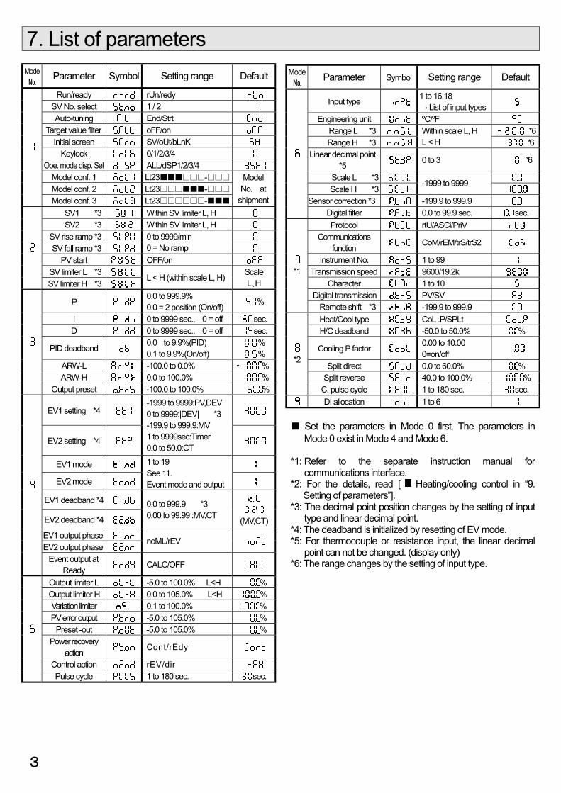
7. List of parameters
Mode Parameter Symbol Setting range Default
Run/ready rUn/redy SV No. select 1 / 2 Auto-tuning End/Strt
Target value filter oFF/on Initial screen SV/oUt/bLnK
Keylock 0/1/2/3/4 Ope. mode disp. Sel ALL/dSP1/2/3/4
Model conf. 1 Lt23- Model conf. 2 Lt23-
Model conf. 3 Lt23-
Model No. at
shipment SV1 *3 Within SV limiter L, H SV2 *3 Within SV limiter L, H
SV rise ramp *3 SV fall ramp *3
0 to 9999/min 0 = No ramp
PV start OFF/on SV limiter L *3
SV limiter H *3 L < H (within scale L, H) Scale
L、H
P 0.0 to 999.9% 0.0 = 2 position (On/off) %
I 0 to 9999 sec., 0 = off sec. D 0 to 9999 sec., 0 = off sec.
PID deadband 0.0 to 9.9%(PID) 0.1 to 9.9%(On/off)
% %
ARW-L -100.0 to 0.0% % ARW-H 0.0 to 100.0% %
Output preset -100.0 to 100.0% %
EV1 setting *4
EV2 setting *4
-1999 to 9999:PV,DEV 0 to 9999:|DEV| *3 -199.9 to 999.9:MV 1 to 9999sec:Timer 0.0 to 50.0:CT
EV1 mode
EV2 mode
1 to 19 See 11. Event mode and output
EV1 deadband *4
EV2 deadband *4
0.0 to 999.9 *3 0.00 to 99.99 :MV,CT
(MV,CT) EV1 output phase
EV2 output phase noML/rEV
Event output at Ready CALC/OFF
Output limiter L -5.0 to 100.0% L<H % Output limiter H 0.0 to 105.0% L<H % Variation limiter 0.1 to 100.0% % PV error output -5.0 to 105.0% %
Preset -out -5.0 to 105.0% % Power recovery
action Cont/rEdy
Control action rEV/dir
Pulse cycle 1 to 180 sec. sec.
Mode Parameter Symbol Setting range Default
Input type 1 to 16,18 → List of input types
Engineering unit ºC/ºF Range L *3 *6 Range H *3
Within scale L, H L < H *6
Linear decimal point *5 0 to 3 *6
Scale L *3 Scale H *3
-1999 to 9999
Sensor correction *3 -199.9 to 999.9
Digital filter 0.0 to 99.9 sec. sec. Protocol rtU/ASCi/PriV
Communications function CoM/rEM/trS/trS2
Instrument No. 1 to 99 Transmission speed 9600/19.2k
Character 1 to 10 Digital transmission PV/SV
*1
Remote shift *3 -199.9 to 999.9 Heat/Cool type CoL .P/SPLt H/C deadband -50.0 to 50.0% %
Cooling P factor 0.00 to 10.00 0=on/off
Split direct 0.0 to 60.0% % Split reverse 40.0 to 100.0% %
*2
C. pulse cycle 1 to 180 sec. sec. DI allocation 1 to 6
Set the parameters in Mode 0 first. The parameters in Mode 0 exist in Mode 4 and Mode 6.
*1: Refer to the separate instruction manual for
communications interface. *2: For the details, read [ Heating/cooling control in “9.
Setting of parameters”]. *3: The decimal point position changes by the setting of input
type and linear decimal point. *4: The deadband is initialized by resetting of EV mode. *5: For thermocouple or resistance input, the linear decimal
point can not be changed. (display only) *6: The range changes by the setting of input type.

8. Description of parameters This chapter describes parameters requiring explanation.
Parameter Function
Run/ready
For selection of control output. ・・・ Preset-out value is displayed in
“OUT”. “AT” cannot be executed. is displayed instead of “SV”.
・・・ Normal control output
Initial screen
This selective screen appears when the power is turned on or the screen returns to the operation screen from the setting screen. The lower LED displays either SV, OUT or with blank.
PV start
It effects when SV rising/SV falling ramp is set. When a trigger signal* applies to SV, SV starts from the point of PV. * At turning on the power, changing SV No.,
changing SV, or switching to SV limiter For limiting the setting range of SV
PID deadband
P≠0: In this deadband, the response of the control output becomes dull due to non-linearized deviation.
P = 0: Deadband of 2-position control
ARW (Anti-reset windup)
For PID control range. This parameter is set to SV by % of SV range. The control out of the ARW range becomes PD control. (The ARW effects to reduce overshoot.)
Output preset
Normally P action controls the calculated output to 50% when the deviation is 0. The calculated output can be set optionally by this parameter.
EV deadband The gap from the event activation to reset.
EV output phase
…Event activation: Relay on, reset: Relay off … Event activation: Relay off, reset: Relay on
Event output at Ready
..The event judgment continues even at Ready. … The event judgment becomes off at Ready
Output limiter
The control output is limited within the set value of L and H.
Variation limiter
The control output is updated per control changing period (about 0.5 sec.). Its variation is limited within the set value.
PV error output This output is for abnormal measured value(PV)*. *Over-range,under-range and Er01,Er03.
Preset-out The control output value during Ready.
Power recovery action
For control action when the power is turned on from off (or from power failure to recovery).
… Continues previous control conditions. … Becomes the “Preset out”.
Control action
Pulse cycle
Applicable to pulse type (On-off pulse type, SSR drive pulse type) control output 1 (heating) The output is based on the time ratio of on to off. This parameter is for the setting of this 1 cycle. The new parameter effects from the next cycle.
Engineering unit
For selection of engineering unit (ºC or ºF) for converting into temperature when thermocouple or resistance thermometer is selected as the input type.
Parameter Function
Range
Minimum value L and maximum value H of the measuring range can be set within the input range selected in the input type. This width (between H and L) becomes 100% of the proportion band P.
Linear decimal
point
The setpoint value (SV) is a figure up to 4 digits and cannot be added with decimal point. For the input types of DC voltage and DC current, the decimal point can be set by this parameter.
Scale
The parameter is for the input types of DC voltage and DC current. The scale with an actual industrial quantity can be set corresponding to Range L and H.
Sensor correction
This function is to correct the measured value (PV) by adding a correction value to the measured value. It can be also used to adjust the measured value to have same display as other equipment.
Digital filter
This function is, by applying the first-order lag computation to the measured value, to reduce the variation of the measured value (PV) due to noise interference.
Cooling pulse cycle
Applicable to control output 2 (cooling) This parameter is for the setting of 1-cycle time of on and off of the output. The list below is for selecting the functions of DI1and DI2. Set value DI1 DI2 1 SV1/2 Run/Ready 2 Timer1 Run/Ready 3 Timer1 SV1/2 4 Timer1 Timer2 5 Run/Ready Remote/Local 6 Timer1 Remote/Local
DI Allocation
* Remote/Local is effective to the optional communications.
100%
Out-
put
0%
Reverse action SV
100%
0%
Direct action SV
A
Delay of PV by filter
Setting range of T(0.0 to 99.9 sec.)
0.63A
T
Variation of measured value
Out-
put
L o w ← P V → H i g h L o w ← P V → H i g h
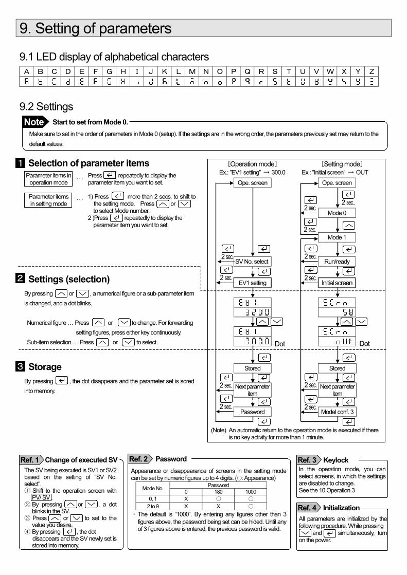
9. Setting of parameters
9.1 LED display of alphabetical characters A B C D E F G H I J K L M N O P Q R S T U V W X Y Z
9.2 Settings
Make sure to set in the order of parameters in Mode 0 (setup). If the settings are in the wrong order, the parameters previously set may return to the default values.
Selection of parameter items Parameter items in
operation mode … Press repeatedly to display the
parameter item you want to set.
Parameter items in setting mode
… 1) Press more than 2 secs. to shift to the setting mode. Press or
to select Mode number. 2 )Press repeatedly to display the parameter item you want to set.
Settings (selection) By pressing or , a numerical figure or a sub-parameter item is changed, and a dot blinks. Numerical figure … Press or to change. For forwarding setting figures, press either key continuously. Sub-item selection … Press or to select.
Storage By pressing , the dot disappears and the parameter set is sored into memory.
[Operation mode] Ex.: ”EV1 setting” → 300.0
[Setting mode] Ex.: ”Initial screen” → OUT
Ope. screen Ope. screen
Mode 0 Mode 1 SV No. select Run/ready EV1 setting Initial screen
Stored Stored
Next parameter item Next parameter
item Password Model conf. 3 (Note) An automatic return to the operation mode is executed if there
is no key activity for more than 1 minute.
The SV being executed is SV1 or SV2 based on the setting of "SV No. select". ① Shift to the operation screen with
PV/ SV . ② By pressing or , a dot
blinks in the SV. ③ Press or to set to the
value you desire. ④ By pressing , the dot disappears and the SV newly set is
stored into memory.
Appearance or disappearance of screens in the setting mode can be set by numeric figures up to 4 digits. (: Appearance)
Password Mode No. 0 180 1000 0, 1 X
2 to 9 X X ・ The default is “1000”. By entering any figures other than 3
figures above, the password being set can be hided. Until any of 3 figures above is entered, the previous password is valid.
In the operation mode, you can select screens, in which the settings are disabled to change. See the 10.Operation 3
All parameters are initialized by the following procedure. While pressing and simultaneously, turn on the power.
Start to set from Mode 0. Note
Change of executed SV Ref. 1 Password Ref. 2 Keylock Ref. 3
1
2
3
Dot Dot
Initialization Ref. 4
2 sec.
2 sec..
2 sec.
2 sec.
2 sec.
2 sec.
2 sec.
2 sec.
2 sec.
2 sec.
2 sec.
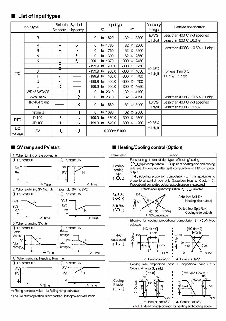
List of input types Selection Symbol Input type Input type
Standard High temp. ºC ºF Accuracy ratings
Detailed specification
B 0 to 1820 32 to 3300 ±0.3% ±1 digit
Less than 400ºC: not specified Less than 800ºC: ±0.6%
R 0 to 1760 32 to 3200 S 0 to 1760 32 to 3200
Less than 400ºC: ± 0.5% ± 1 digit
N 0 to 1300 32 to 2350 K -200 to 1370 -300 to 2450 E - -199.9 to 700.0 -300 to 1250 J - -199.9 to 900.0 -300 to 1650 T - -199.9 to 400.0 -300 to 700 U - -199.9 to 400.0 -300 to 700 L - -199.9 to 900.0 -300 to 1650
WRe5-WRe26 - 0 to 2310 32 to 4190
For less than 0ºC, ± 0.5% ± 1 digit
W-WRe26 - 0 to 2310 32 to 4190
±0.25% ±1 digit
Less than 400ºC: ± 0.5% ± 1 digit PtRh40-PtRh2
0 - 0 to 1880 32 to 3400 ±0.5% ±1 digit
Less than 400ºC: not specified Less than 800ºC: ±1.5%
T/C
PlatinelⅡ - 0 to 1390 32 to 2500 Pt100 -199.9 to 850.0 -300 to 1500 RTD JPt100 -199.9 to 649.0 -300 to 1200
DC voltage 5V 0.000 to 5.000
±0.25% ±1 digit
SV ramp and PV start 1) When turning on the power, ① PV start: OFF ② PV start: ON
2) When switching SV No., … Example: SV1 to SV2 ① PV start: OFF ② PV start: ON
3) When changing SV, ① PV start: OFF ② PV start: ON
4) When switching Ready to Run ,
① PV start: OFF ② PV start: ON
H: Rising ramp set value L: Falling ramp set value * The SV ramp operation is not backed up for power interruption.
Heating/Cooling control (Option)
Parameter Function
Heating/ cooling type
( )
For selecting of computation types of heating/cooling (Split computation) … Outputs at heating side and cooling
side are the outputs after split computation of PID computed output.
(Cooling proportion computation) … It is applicable to proportional control type only (2-position type for CooL = 0). Proportional computed output at cooling side is executed.
Effective for split computation ( ) selected Split Dir. ( )
Split Rev. ( )
Solid line: Split Dir. (Heating side output) Dotted line: Split Rev. (Cooling side output)
Effective for cooling proportional computation ( ) type selected
[HC db > 0] [HC db < 0]
H・C dead band ( )
: Heating side SV : Cooling side SV Cooling side proportional band = Proportional band (P) x Cooling P factor ( )
[P = 0] [P≠0 and Cool = 0]
Cooling P factor ( )
: Heating side SV : Cooling side SV db: PID dead band (common for heating and cooling sides)
SV PV
Time
SV PV
Time
H
SV1 SV2
Time
L
PV
SV1 SV2
Time
H PV
Before change
After change
Time
L PV
Before change
After change
Time
L PV
SV PV
Time
SV PV
Time
H
50
0
100
40 60 100(%) PID computation
Out
put
50
0
100
Heat Cool
HC db
Out
put
PV
50
0
100
Heat Cool
HC db
Out
put
PV
Heat
Cool
HC db
db
Out
put
PV
db db
Heat Cool
HC db
Out
put
PV
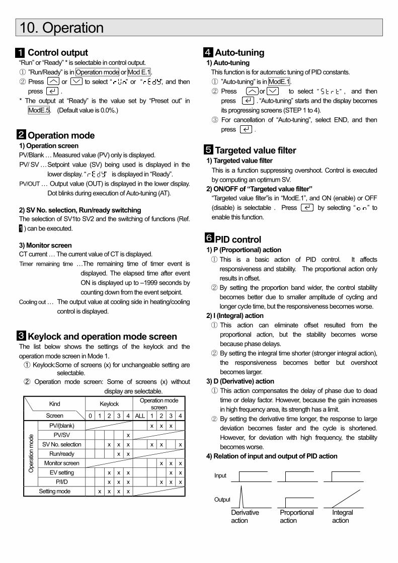
10. Operation Control output “Run” or “Ready” * is selectable in control output. ① ”Run/Ready” is in Operation mode or Mod E.1. ② Press or to select “ ” or “ ”, and then
press . * The output at “Ready” is the value set by “Preset out” in
ModE.5. (Default value is 0.0%.)
Operation mode 1) Operation screen PV/Blank … Measured value (PV) only is displayed. PV/ SV … Setpoint value (SV) being used is displayed in the
lower display. “ ” is displayed in “Ready”. PV/OUT … Output value (OUT) is displayed in the lower display.
Dot blinks during execution of Auto-tuning (AT). 2) SV No. selection, Run/ready switching The selection of SV1to SV2 and the switching of functions (Ref. 1 ) can be executed. 3) Monitor screen CT current … The current value of CT is displayed. Timer remaining time …The remaining time of timer event is
displayed. The elapsed time after event ON is displayed up to –1999 seconds by counting down from the event setpoint.
Cooling out … The output value at cooling side in heating/cooling control is displayed.
Keylock and operation mode screen The list below shows the settings of the keylock and the operation mode screen in Mode 1. ① Keylock: Some of screens (x) for unchangeable setting are
selectable. ② Operation mode screen: Some of screens (x) without
display are selectable.
Kind Keylock Operation mode screen
Screen 0 1 2 3 4 ALL 1 2 3 4 PV/(blank) x x x
PV/SV x SV No. selection x x x x x x
Run/ready x x Monitor screen x x x
EV setting x x x x x Ope
ratio
n m
ode
P/I/D x x x x x x Setting mode x x x x
Auto-tuning 1) Auto-tuning
This function is for automatic tuning of PID constants. ① ”Auto-tuning” is in ModE.1. ② Press or to select ” ” , and then
press . “Auto-tuning” starts and the display becomes its progressing screens (STEP 1 to 4).
③ For cancellation of “Auto-tuning”, select END, and then press .
Targeted value filter 1) Targeted value filter
This is a function suppressing overshoot. Control is executed by computing an optimum SV.
2) ON/OFF of “Targeted value filter” “Targeted value filter”is in “ModE.1”, and ON (enable) or OFF (disable) is selectable . Press by selecting “ ” to enable this function.
PID control 1) P (Proportional) action ① This is a basic action of PID control. It affects
responsiveness and stability. The proportional action only results in offset.
② By setting the proportion band wider, the control stability becomes better due to smaller amplitude of cycling and longer cycle time, but the responsiveness becomes worse.
2) I (Integral) action ① This action can eliminate offset resulted from the
proportional action, but the stability becomes worse because phase delays.
② By setting the integral time shorter (stronger integral action), the responsiveness becomes better but overshoot becomes larger.
3) D (Derivative) action ① This action compensates the delay of phase due to dead
time or delay factor. However, because the gain increases in high frequency area, its strength has a limit.
② By setting the derivative time longer, the response to large deviation becomes faster and the cycle is shortened. However, for deviation with high frequency, the stability becomes worse.
4) Relation of input and output of PID action
Input
Output
Derivative action
Proportional action
Integral action
1 4
5
6
2
3
4
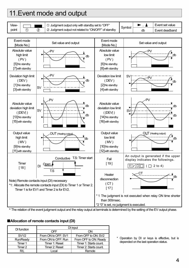
11.Event mode and output
, Event set value View- point
① Judgment output only with standby set to “OFF” ② Judgment output not related to “ON/OFF” of standby
Symbol db Event deadband
Event mode [Mode No.] Set value and output Event mode
[Mode No.] Set value and output
Absolute value high limit
( PV ) [ 5 ] No standby [ 7 ] with standby
Absolute value low limit ( PV )
[ 6 ] No standby [ 8 ] with standby
Deviation high limit ( DEV )
[ 1 ] No standby [ 3 ] with standby
Deviation low limit ( DEV )
[ 2 ] No standby [ 4 ] with standby
Absolute value deviation high limit
( |DEV| ) [ 13 ] No standby [ 15 ] with standby
Absolute value deviation low limit
( |DEV| ) [ 14 ] No standby [ 16 ] with standby
Output value high limit
( MV ) [ 9 ] No standby
[ 11 ] with standby
Output value low limit ( MV )
[ 10 ] No standby [ 12 ] with standby
Fail [ 19 ]
An output is generated if the upper display indicates the followings.
( : 2 to 4)
Timer [ 18 ]
Heater disconnection
( CT ) [ 17 ]
Note) Remote contacts input (DI) necessary *1: Allocate the remote contacts input (DI) to Timer 1 or Timer 2.
Timer 1 is for EV1 and Timer 2 is for EV2.
* 1 The judgment is not executed when relay ON time shorter than 300msec. *2 “0” is set, no judgment is executed.
* The relation of the event judgment output and the relay output at terminals is determined by the setting of the EV output phase.
Allocation of remote contacts input (DI) DI input DI function OFF ON
SV1/2 From ON to OFF: SV1 From OFF to ON: SV2 Run/Ready From ON to OFF: Run From OFF to ON: Ready
Timer 1 Timer 1: Reset Timer 1: Starts count. Timer 2 Timer 2: Reset Timer 2: Starts count.
R/L Local Remote
db PV
db PV
db PV
SV
db
PV
db SV
db PV SV
db
PV
db SV
① ②
CT db
OUT (Heating output) db
OUT (Heating output) db
Conductive
T.S
Open DI
T.S: Timer start
* Operation by DI or keys is effective, but is depended on the last operation status.