ltq orbitrap xl - thermo fisher scientific · ltq orbitrap xl is a member of the family of ltq™...
TRANSCRIPT
For Research Use OnlyNot for use in Diagnostic Procedures
LTQ Orbitrap XL™
Getting Started 2.4
119 0822 Revision A - May 2007
© 2007 Thermo Fisher Scientific Inc. All rights reserved.
“Swagelok” is a registered trademark of the Crawford Fitting Company. “Teflon” is a registered trademark of E. I. du Pont de Nemours & Co.
All other trademarks are the property of Thermo Fisher Scientific Inc. and its subsidiaries.
Thermo Fisher Scientific Inc. provides this document to its customers with a product purchase to use in the product operation. This document is copyright protected and any reproduction of the whole or any part of this document is strictly prohibited, except with the written authorization of Thermo Fisher Scientific Inc.
The contents of this document are subject to change without notice. All technical information in this document is for reference purposes only. System configurations and specifications in this document supersede all previous information received by the purchaser.
Thermo Fisher Scientific Inc. makes no representations that this document is complete, accurate or error-free and assumes no responsibility and will not be liable for any errors, omissions, damage or loss that might result from any use of this document, even if the information in the document is followed properly.
This document is not part of any sales contract between Thermo Fisher Scientific Inc. and a purchaser. This document shall in no way govern or modify any Terms and Conditions of Sale, which Terms and Conditions of Sale shall govern all conflicting information between the two documents.
Printing History: Revision A printed in May 2007.
WEEE KonformitätDieses Produkt muss die EU Waste Electrical & Electronic Equipment (WEEE) Richtlinie 2002/96/EC erfüllen. Das Produkt ist durch folgendes Symbol gekennzeichnet:
Thermo Fisher Scientific hat Vereinbarungen getroffen mit Verwertungs-/Entsorgungsanlagen in allen EU-Mitgliederstaaten und dieses Produkt muss durch diese Firmen wiederverwertet oder entsorgt werden. Mehr Informationen über die Einhaltung dieser Anweisungen durch Thermo Fisher Scientific, die Verwerter und Hinweise die Ihnen nützlich sein können, die Thermo Fisher Scientific Produkte zu identifizieren, die unter diese RoHS Anweisung fallen, finden Sie unter www.thermo.com/WEEERoHS.
WEEE ComplianceThis product is required to comply with the European Union’s Waste Electrical & Electronic Equipment (WEEE) Directive 2002/96/EC. It is marked with the following symbol:
Thermo Fisher Scientific has contracted with one or more recycling/disposal companies in each EU Member State, and this product should be disposed of or recycled through them. Further information on Thermo Fisher Scientific’s compliance with these Directives, the recyclers in your country, and information on Thermo Fisher Scientific products which may assist the detection of substances subject to the RoHS Directive are available at www.thermo.com/WEEERoHS.
Conformité DEEECe produit doit être conforme à la directive européenne (2002/96/EC) des Déchets d'Equipements Electriques et Electroniques (DEEE). Il est marqué par le symbole suivant:
Thermo Fisher Scientific s'est associé avec une ou plusieurs compagnies de recyclage dans chaque état membre de l’union européenne et ce produit devrait être collecté ou recyclé par celles-ci. Davantage d'informations sur la conformité de Thermo Fisher Scientific à ces directives, les recycleurs dans votre pays et les informations sur les produits Thermo Fisher Scientific qui peuvent aider la détection des substances sujettes à la directive RoHS sont disponibles sur www.thermo.com/WEEERoHS.
Read This First
Welcome to the Thermo Scientific, LTQ Orbitrap XL™ system! The LTQ Orbitrap XL is a member of the family of LTQ™ mass spectrometer (MS) detectors.
Who Uses This Guide This LTQ Orbitrap XL Getting Started manual is intended for all personnel that needs to operate the LTQ Orbitrap XL, especially the key operator. This manual should be kept near the instrument to be available for quick reference.
Scope of this Guide This LTQ Orbitrap XL Getting Started manual provides you with information on how to set up, calibrate, and tune the LTQ Orbitrap XL. Procedures in Chapters 1–4 can be performed from the Xcalibur® Tune Plus window.
LTQ Orbitrap XL Getting Started includes the following chapters:
• Chapter 1: “Introduction” provides general information about this manual.
• Chapter 2: “Tune Plus Window” provides information on the Tune Plus window.
• Chapter 3: “Calibrating the Orbitrap XL for FTMS Measurements” provides procedures to calibrate your LTQ Orbitrap XL for FTmeasurements.
• Chapter 4: “Performing Diagnostics/Checks” describes several diagnostic procedures.
• Chapter 5: “Instrument Setup” describes the FT relevant topics of the data dependent settings in the Instrument Setup.
• Chapter 6: “Instrument Configuration” gives instructions about configuring your instrument.
• Appendix A: “Miscellaneous Information” gives additional information about various topics.
Thermo Fisher Scientific LTQ Orbitrap XL Getting Started i
Read This FirstChanges to the Manual
Changes to theManual
To suggest changes to this manual, please send your comments to:
Editors, Technical DocumentationThermo Fisher ScientificHanna-Kunath-Str. 11
28199 Bremen
Germany
You are encouraged to report errors or omissions in the text or index.Thank you.
ii LTQ Orbitrap XL Getting Started Thermo Fisher Scientific
Read This FirstTypographical Conventions
TypographicalConventions
Typographical conventions have been established for Thermo Fisher Scientific manuals for the following:
• Data input
• Admonitions
• Topic headings
Data Input Throughout this manual, the following conventions indicate data input and output via the computer:
• Messages displayed on the screen are represented by capitalizing the initial letter of each word and by italicizing each word.
• Input that you enter by keyboard is identified by quotation marks: single quotes for single characters, double quotes for strings.
• For brevity, expressions such as “choose File > Directories” are used rather than “pull down the File menu and choose Directories.”
• Any command enclosed in angle brackets < > represents a single keystroke. For example, “press <F1>” means press the key labeled F1.
• Any command that requires pressing two or more keys simultaneously is shown with a plus sign connecting the keys. For example, “press <Shift> + <F1>” means press and hold the <Shift> key and then press the <F1> key.
• Any button that you click on the screen is represented in bold face letters. For example, “click on Close”.
Thermo Fisher Scientific LTQ Orbitrap XL Getting Started iii
Read This FirstTypographical Conventions
Admonitions Admonitions contain information that is important, but not part of the main flow of text.
Admonitions can be of the following types:
• Note – information that can affect the quality of your data. In addition, notes often contain information that you might need if you are having trouble.
• Caution – information necessary to protect your instrument from damage.
• Warning – hazards to human beings. Each Warning is accompanied by a Warning symbol.
Topic Headings The following headings are used to show the organization of topics within a chapter:
Chapter Name
The following headings appear in the left column of each page:
Second Level Topics
Third Level Topics
Fourth Level Topics
iv LTQ Orbitrap XL Getting Started Thermo Fisher Scientific
Read This FirstSafety and EMC Information
Safety and EMCInformation
In accordance with our commitment to customer service and safety, these instruments have satisfied the requirements for the European CE Mark including the Low Voltage Directive.
Designed, processor and tested in an ISO9001 registered facility, this instrument has been shipped to you from our manufacturing facility in a safe condition.
Caution This instrument must be used as described in this manual. Any use of this instrument in a manner other than described here may result in instrument damage and/or operator injury.
Identifying SafetyInformation
The LTQ Orbitrap XL Getting Started contains precautionary statements that can prevent personal injury, instrument damage, and loss of data if properly followed. Warning symbols which alert the user to check for hazardous conditions appear throughout the manual, where applicable, and are defined in Table i.
Table i. Warning Symbols
Symbol Description
General This general symbol indicates that a hazard is present, which if not avoided, could result in injuries.
The source of danger is described in the accompanying text.
Electric Shock High voltages capable of causing personal injury are used in the instrument. The instrument must be shut down and disconnected from line power before service or repair work is performed.
Hot Surface / Heat Allow heated components to cool down before servicing them!
Thermo Fisher Scientific LTQ Orbitrap XL Getting Started v
Read This FirstSafety and EMC Information
Instrument-SpecificHazards
Every instrument has specific hazards, so be sure to read and comply with the following precautions. They will help ensure the safe, long-term use of your system.
1. Before plugging in any of the instrument modules or turning on the power, always make sure that the voltage and fuses are set appropriately for your local line voltage.
2. Only use fuses of the type and current rating specified. Do not use repaired fuses and do not short-circuit the fuse holder.
3. The supplied power cord must be inserted into a power outlet with a protective earth contact (ground). When using an extension cord, make sure that the cord also has an earth contact.
4. Do not change the external or internal grounding connections.Tampering with or disconnecting these connections could endanger you and/or damage the system.
Caution The instrument is properly grounded in accordance with regulations when shipped. You do not need to make any changes to the electrical connections or to the instrument’s chassis to ensure safe operation.
5. Never run the system without the housing on. Permanent damage can occur.
6. Do not turn the instrument on if you suspect that it has incurred any kind of electrical damage. Instead, disconnect the power cord and contact a service representative for a product evaluation. Do not attempt to use the instrument until it has been evaluated. (Electrical damage may have occurred if the system shows visible signs of damage, or has been transported under severe stress.)
7. Damage can also result if the instrument is stored for prolonged periods under unfavorable conditions (e.g., subjected to heat, water, etc.).
8. Always disconnect the power cord before attempting any type of maintenance.
vi LTQ Orbitrap XL Getting Started Thermo Fisher Scientific
Read This FirstSafety and EMC Information
9. Capacitors inside the instrument may still be charged even if the instrument is turned off.
10. Never try to repair or replace any component of the system that is not described in this manual without the assistance of your service representative.
Thermo Fisher Scientific LTQ Orbitrap XL Getting Started vii

Contents
Chapter 1 Introduction................................................................................1-1
Chapter 2 Tune Plus Window....................................................................2-1Preliminary Remarks ......................................................... 2-2View Menu ....................................................................... 2-3
Spectrum View............................................................... 2-3Graph View ................................................................... 2-5Status View .................................................................... 2-5
Control Menu................................................................... 2-8Advanced Calibration Features....................................... 2-8
Scan Mode Menu.............................................................. 2-9Define Scan.................................................................... 2-9Scan Ranges ................................................................. 2-13Centroid/Profile ........................................................... 2-13Positive/Negative ......................................................... 2-14
Display Menu ................................................................. 2-15Spectrum Averaging ..................................................... 2-15
Setup Menu .................................................................... 2-16FT Transfer Optics ...................................................... 2-16FT Injection Control ................................................... 2-16FT Vacuum ................................................................. 2-19FT Temperature Monitor ............................................ 2-19
Tune Methods ................................................................ 2-21Parameters with Differentiation between Ion Trap and FT Scans ...................................................................... 2-21Parameters without Differentiation between Ion Trap and FT Scans ...................................................................... 2-22Parameters not saved in a Tunefile ............................... 2-22
Chapter 3 Calibrating the Orbitrap XL for FTMS Measurements........3-1Preliminary Remarks ......................................................... 3-2Calibration Files and their Backups................................... 3-3
Backup Current Calibration........................................... 3-3Restore Backup Calibration............................................ 3-3
Calibration Solutions ........................................................ 3-4LTQ Calibration Solution.............................................. 3-4LTQ Orbitrap XL Calibration Solution ......................... 3-6Applicable Calibration Solutions for Automatic Calibration3-7Applicable Calibration Solutions for Semi-Automatic Calibration..................................................................... 3-7
Thermo Fisher Scientific LTQ Orbitrap XL Getting Started ix
Contents
Applicable Calibration Solutions for FT Manual Calibration3-7
Calibration and Tuning of the Ion Trap ........................... 3-8Calibration of the Ion Trap............................................ 3-8Tuning the Ion Trap for Positive Ion Mode................... 3-8Tuning the Ion Trap for Negative Ion Mode ............... 3-10
Automatic Calibration Page ............................................ 3-11Semi-Automatic Calibration Page ................................... 3-12
HCD Calibration......................................................... 3-13Advanced Calibration Features..................................... 3-13
Check Calibration Page................................................... 3-15FT Manual Calibration Page........................................... 3-18
Mass List Group Box ................................................... 3-19
Chapter 4 Performing Diagnostics/Checks............................................ 4-1System Evaluation Procedures ........................................... 4-2
FT Temperature Monitor .............................................. 4-3FT Temperature Control Evaluation.............................. 4-3FT Preamp Evaluation ................................................... 4-3FT Sensitivity Test ......................................................... 4-3FT Noise Test ................................................................ 4-4FT Isolation Test ........................................................... 4-4FT Dynamic Range Test ................................................ 4-4FT Stability Test ............................................................ 4-4FT High Mass Range Target Compensation .................. 4-5
Toggles ............................................................................. 4-6FT Analyzer Ion Gauge.................................................. 4-7FT Analyzer Temperature Control................................. 4-7FT Apodization.............................................................. 4-7FT HCD Collision Gas.................................................. 4-7FT Include Transients.................................................... 4-7FT Storage Multipole RF ............................................... 4-7FT Transfer Multipole RF ............................................. 4-7FT Manual Calibration for Single Range ....................... 4-8FT Multiple C-Trap Fills ............................................... 4-8FT Profile Mode ............................................................ 4-8FT SIM and MSn Injection Waveforms......................... 4-8FT View Frequency........................................................ 4-8FT Zero Offset............................................................... 4-9
Set Device ....................................................................... 4-10FT Lockmass Abundance ............................................. 4-11FT Mass Check Test Duration..................................... 4-11Setting new FT Transfer Optics Parameters ................. 4-11
Display Settings .............................................................. 4-12Display FT Calibration Settings ................................... 4-12Display FT Diagnostics................................................ 4-13Display FT Instrument Settings ................................... 4-13
x LTQ Orbitrap XL Getting Started Thermo Fisher Scientific
Contents
Chapter 5 Instrument Setup .......................................................................5-1Using Locking in Automated Runs ................................... 5-2Data Dependent Settings .................................................. 5-3
Preview Mode ................................................................ 5-3Monoisotopic Precursor Selection .................................. 5-4Use Non-Peptide Monoisotopic Recognition................. 5-4Data Dependent FT SIM Scans ..................................... 5-5Activation Type ............................................................. 5-8FT HCD........................................................................ 5-9
MSn Settings for HCD Experiments............................... 5-10
Chapter 6 Instrument Configuration.........................................................6-1Starting Instrument Configuration.................................... 6-2FT Settings Page ............................................................... 6-3FT Mass Lists Page............................................................ 6-4
Appendix A Miscellaneous Information....................................................A-1FT Analyzer Information in Scan Header..........................A-2
FT Analyzer Settings ......................................................A-2FT Analyzer Messages ....................................................A-3
Data Size of FT Raw Files .................................................A-4
Glossary .....................................................................................G-1
Index............................................................................................ I-1
Thermo Fisher Scientific LTQ Orbitrap XL Getting Started xi

Contents
xii LTQ Orbitrap XL Getting Started Thermo Fisher Scientific
Figures
Tune Plus window ................................................................................ 2-2Spectrum View page .............................................................................. 2-3Spectrum Display Options dialog box - FT page ................................... 2-4Graph view page ................................................................................... 2-5Status view page - All page .................................................................... 2-6User Status Display Configuration dialog box ....................................... 2-7Define Scan dialog box .......................................................................... 2-9Lock Masses dialog box ....................................................................... 2-11Define Scan dialog box with HCD selected as activation type ............. 2-13Spectrum Averaging dialog box ........................................................... 2-15FT Transfer Optics dialog box ............................................................ 2-16Ion Trap page of the Injection Control dialog box .............................. 2-17FT page of the Injection Control dialog box ....................................... 2-18Ion Trap page of the Vacuum dialog box ............................................ 2-19FT page of the Vacuum dialog box ..................................................... 2-19FT Temperature Monitor dialog box .................................................. 2-20Recommended settings in the Define Scan dialog box for an automatic tune of the ion trap ....................................................................................... 3-9Ion trap spectrum of the LTQ Orbitrap XL calibration solution, scan range 120–2000, positive ion polarity mode ......................................... 3-9Ion trap spectrum of the LTQ Orbitrap XL calibration solution, scan range 150–2000, negative ion mode ................................................... 3-10Automatic page of the Calibrate dialog box ......................................... 3-11Semi-Automatic page of the Calibrate dialog box ................................ 3-12Semi-Automatic page of the Calibrate dialog box (Advanced Calibration Features enabled) ................................................................................ 3-14Check page of the Calibrate dialog box ............................................... 3-15FT Manual page of the Calibrate dialog box ....................................... 3-18System evaluation page of the Diagnostics dialog box ............................ 4-2Result of the FT stability test displayed in the Graph View ................... 4-5Toggles page of the Diagnostics dialog box ........................................... 4-6Set device page of the Diagnostics dialog box ...................................... 4-10Display settings page of the Diagnostics dialog box ............................. 4-12MS Detector Setup View - MS Detector Setup Page ............................. 5-2Data Dependent Settings dialog box – Current Segment page .............. 5-3Charge State page of the Data dependent settings dialog box with Advanced Features on ............................................................................................ 5-4Data Dependent Settings dialog box – Current Scan Event page ........... 5-5 Current Scan Event page - Repeat previous scan event with HCD ....... 5-6Data Dependent Settings dialog box – Scan Widths page ..................... 5-7Data Dependent Settings dialog box – Activation page ......................... 5-8Data Dependent Settings dialog box – FT HCD page .......................... 5-9MS Detector Setup Page - Scan event settings with HCD experiment 5-10
Thermo Fisher Scientific LTQ Orbitrap XL Getting Started xiii
Figures
Instrument Configuration dialog box .................................................... 6-2LTQ Orbitrap XL Configuration dialog box – FT Settings page ........... 6-3LTQ Orbitrap XL Configuration dialog box – FT Mass Lists page ....... 6-4
xiv LTQ Orbitrap XL Getting Started Thermo Fisher Scientific
Tables
Actual settings of manual toggles ...........................................................A-2Typical data sizes (per scan) of an FT spectrum .....................................A-4
Thermo Fisher Scientific LTQ Orbitrap XL Getting Started <~Page Number>xv

Tables
<~Page Number>xvi LTQ Orbitrap XL Getting Started Thermo Fisher Scientific
Chapter 1 Introduction
This manual describes only the FTMS detector relevant settings and procedures of the LTQ Orbitrap XL software (Tune plus version 2.4). For ion trap relevant settings and procedures, refer to the LTQ XL Getting Started manual.
In addition to this manual, the LTQ Orbitrap XL Tune Plus Online Help gives information to specific topics. Nevertheless, it is recommended to read this manual entirely.
Thermo Fisher Scientific LTQ Orbitrap XL Getting Started 1-1

Chapter 2 Tune Plus Window
This chapter provides LTQ Orbitrap XL specific information about the Tune Plus window. It contains the following topics:
• “Preliminary Remarks” on page 2-2
• “View Menu” on page 2-3
• “Scan Mode Menu” on page 2-9
• “Display Menu” on page 2-15
• “Setup Menu” on page 2-16
• “Tune Methods” on page 2-21
Thermo Fisher Scientific LTQ Orbitrap XL Getting Started 2-1
Tune Plus WindowPreliminary Remarks
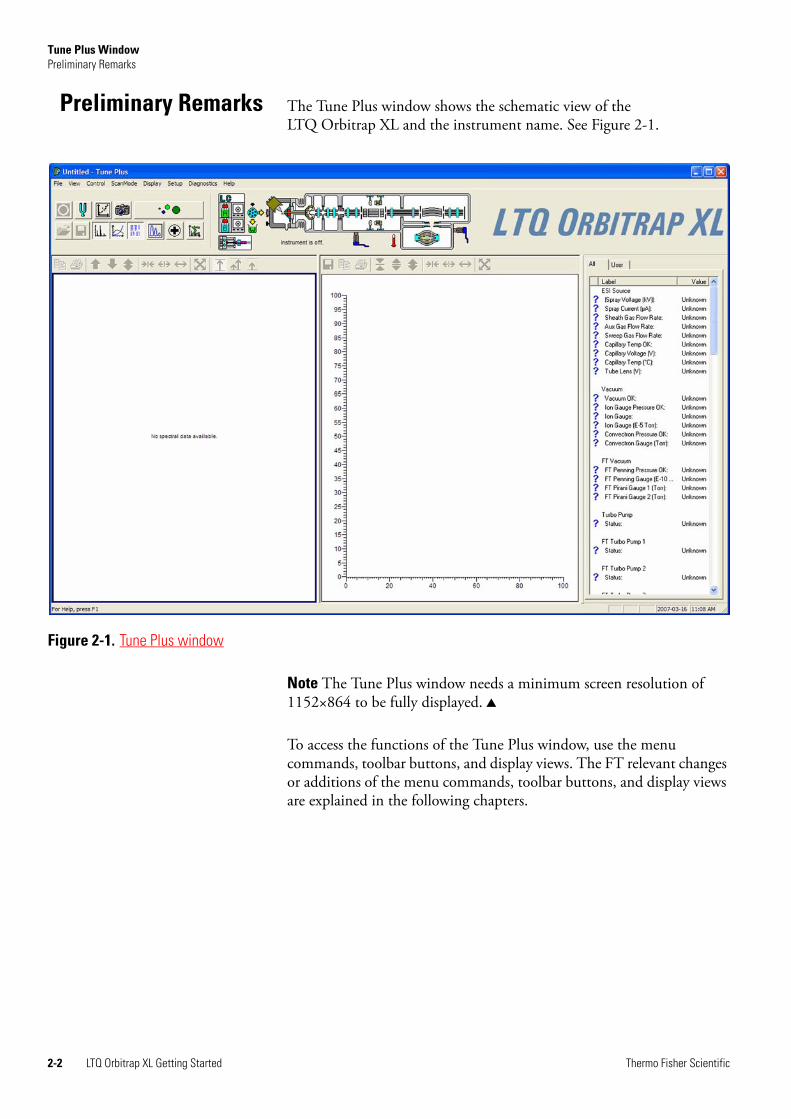
Preliminary Remarks The Tune Plus window shows the schematic view of the LTQ Orbitrap XL and the instrument name. See Figure 2-1.
Note The Tune Plus window needs a minimum screen resolution of 1152×864 to be fully displayed.
To access the functions of the Tune Plus window, use the menu commands, toolbar buttons, and display views. The FT relevant changes or additions of the menu commands, toolbar buttons, and display views are explained in the following chapters.
Figure 2-1. Tune Plus window
2-2 LTQ Orbitrap XL Getting Started Thermo Fisher Scientific
Tune Plus WindowView Menu
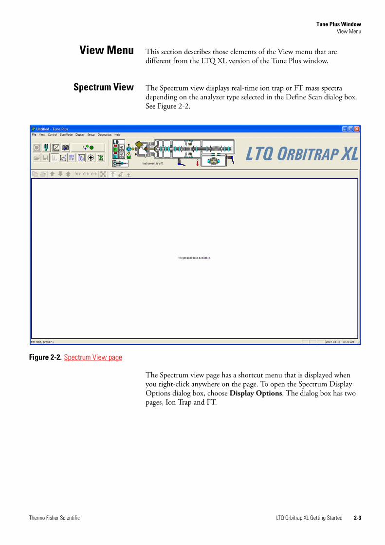
View Menu This section describes those elements of the View menu that are different from the LTQ XL version of the Tune Plus window.
Spectrum View The Spectrum view displays real-time ion trap or FT mass spectra depending on the analyzer type selected in the Define Scan dialog box. See Figure 2-2.
The Spectrum view page has a shortcut menu that is displayed when you right-click anywhere on the page. To open the Spectrum Display Options dialog box, choose Display Options. The dialog box has two pages, Ion Trap and FT.
Figure 2-2. Spectrum View page
Thermo Fisher Scientific LTQ Orbitrap XL Getting Started 2-3
Tune Plus WindowView Menu
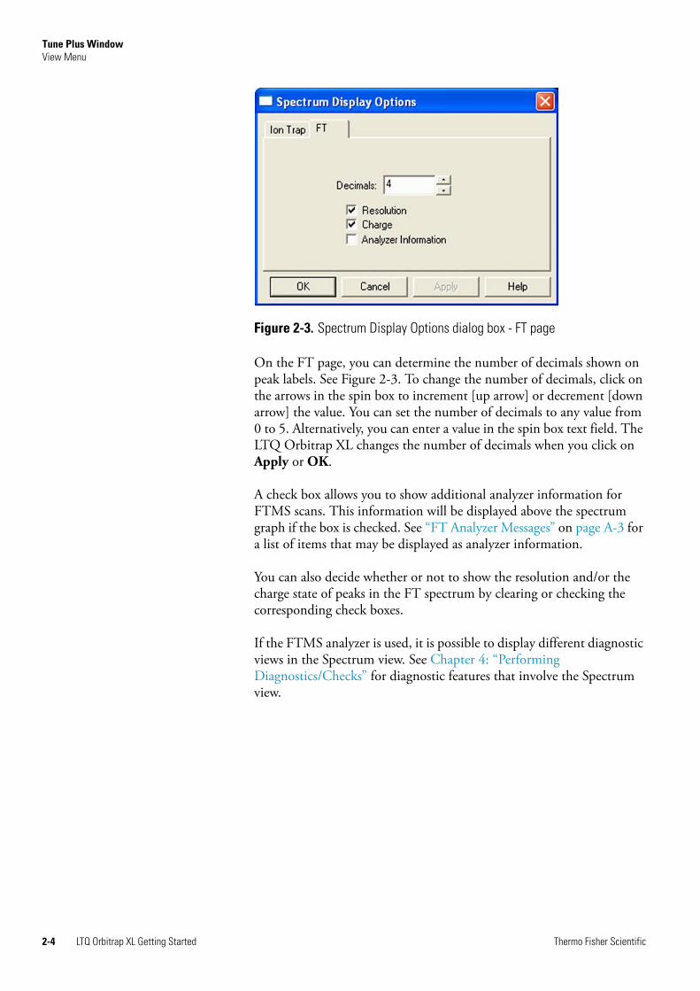
On the FT page, you can determine the number of decimals shown on peak labels. See Figure 2-3. To change the number of decimals, click on the arrows in the spin box to increment [up arrow] or decrement [down arrow] the value. You can set the number of decimals to any value from 0 to 5. Alternatively, you can enter a value in the spin box text field. The LTQ Orbitrap XL changes the number of decimals when you click on Apply or OK.
A check box allows you to show additional analyzer information for FTMS scans. This information will be displayed above the spectrum graph if the box is checked. See “FT Analyzer Messages” on page A-3 for a list of items that may be displayed as analyzer information.
You can also decide whether or not to show the resolution and/or the charge state of peaks in the FT spectrum by clearing or checking the corresponding check boxes.
If the FTMS analyzer is used, it is possible to display different diagnostic views in the Spectrum view. See Chapter 4: “Performing Diagnostics/Checks” for diagnostic features that involve the Spectrum view.
Figure 2-3. Spectrum Display Options dialog box - FT page
2-4 LTQ Orbitrap XL Getting Started Thermo Fisher Scientific
Tune Plus WindowView Menu
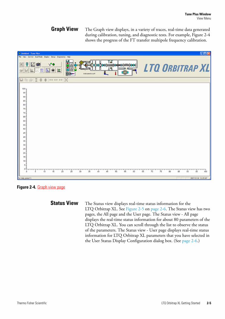
Graph View The Graph view displays, in a variety of traces, real-time data generated during calibration, tuning, and diagnostic tests. For example, Figure 2-4 shows the progress of the FT transfer multipole frequency calibration.
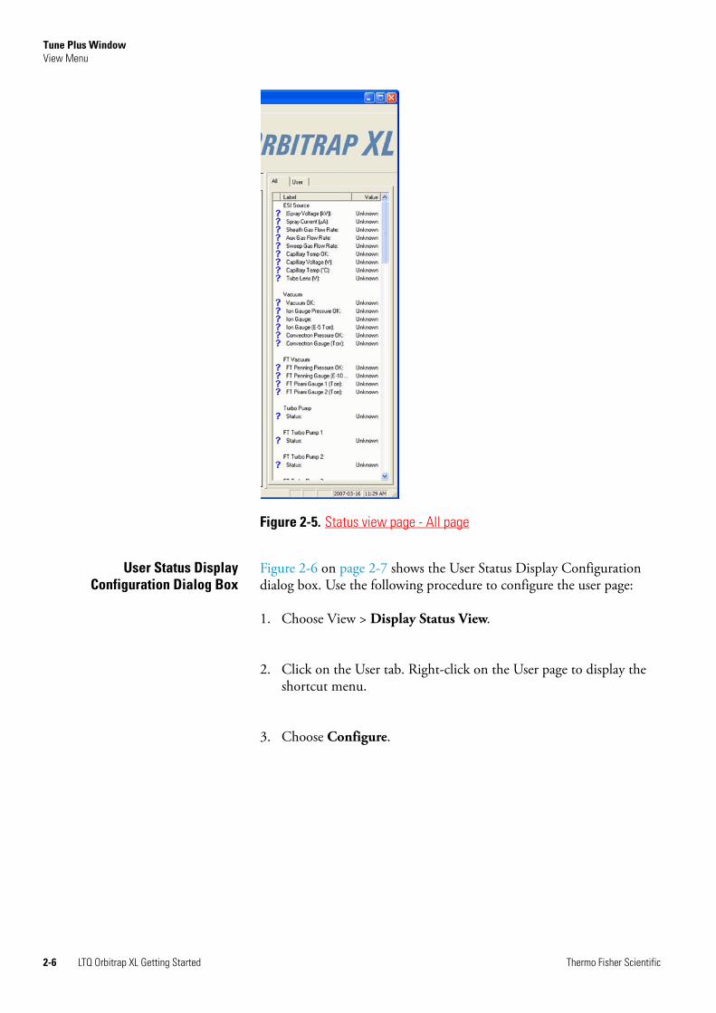
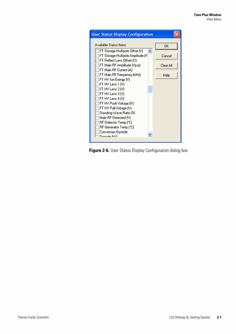
Status View The Status view displays real-time status information for the LTQ Orbitrap XL. See Figure 2-5 on page 2-6. The Status view has two pages, the All page and the User page. The Status view - All page displays the real-time status information for about 80 parameters of the LTQ Orbitrap XL. You can scroll through the list to observe the status of the parameters. The Status view - User page displays real-time status information for LTQ Orbitrap XL parameters that you have selected in the User Status Display Configuration dialog box. (See page 2-6.)
Figure 2-4. Graph view page
Thermo Fisher Scientific LTQ Orbitrap XL Getting Started 2-5
Tune Plus WindowView Menu
User Status DisplayConfiguration Dialog Box
Figure 2-6 on page 2-7 shows the User Status Display Configuration dialog box. Use the following procedure to configure the user page:
1. Choose View > Display Status View.
2. Click on the User tab. Right-click on the User page to display the shortcut menu.
3. Choose Configure.
Figure 2-5. Status view page - All page
2-6 LTQ Orbitrap XL Getting Started Thermo Fisher Scientific
Tune Plus WindowView Menu
Figure 2-6. User Status Display Configuration dialog box
Thermo Fisher Scientific LTQ Orbitrap XL Getting Started 2-7
Tune Plus WindowControl Menu
Control Menu This section describes the elements of the Control menu that are different from the LTQ XL.
Advanced CalibrationFeatures
Use the Advanced Calibration Features command to display advanced features on the Semi-Automatic page of the Calibrate dialog box, such as storage transmission and the FT transmission (See Figure 3-6 on page 3-14.):
• If the command is displayed as “Advanced Scan Features” this indicates that the command is disabled. Normal features will be displayed.
• If the command is displayed as “ Advanced Scan Features” this indicates that the command is enabled. Advanced features will be displayed.
Activate/deactivate this command by choosing Control > Advanced Calibration Features.
2-8 LTQ Orbitrap XL Getting Started Thermo Fisher Scientific
Tune Plus WindowScan Mode Menu
Scan Mode Menu This section describes the elements of the Scan Mode menu that are different from the LTQ XL.
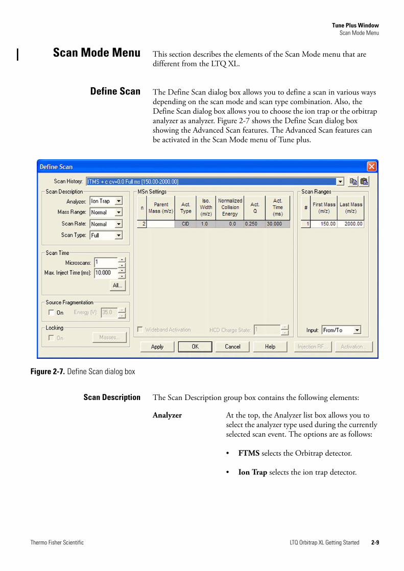
Define Scan The Define Scan dialog box allows you to define a scan in various ways depending on the scan mode and scan type combination. Also, the Define Scan dialog box allows you to choose the ion trap or the orbitrap analyzer as analyzer. Figure 2-7 shows the Define Scan dialog box showing the Advanced Scan features. The Advanced Scan features can be activated in the Scan Mode menu of Tune plus.
Scan Description The Scan Description group box contains the following elements:
Figure 2-7. Define Scan dialog box
Analyzer At the top, the Analyzer list box allows you to select the analyzer type used during the currently selected scan event. The options are as follows:
• FTMS selects the Orbitrap detector.
• Ion Trap selects the ion trap detector.
Thermo Fisher Scientific LTQ Orbitrap XL Getting Started 2-9
Tune Plus WindowScan Mode Menu
Scan Time The Scan Time group box contains the following elements:
Mass Range The following mass ranges are available:
• Low: 15–200 for ion trap analyzer only
• Normal: 50–2000 for ion trap and FTMS analyzer
• High: 100–4000 for ion trap and FTMS analyzer
Scan Rate / Resolution
When you have selected the entry ion trap in the Analyzer list box, this list box allows you to set the scan rate (Normal, Enhanced, Turbo, Zoom, UltraZoom).
When you have selected the entry FTMS in the Analyzer list box, this list box allows you to set the resolution of the FT mass spectra. The mass resolution is selectable between several options. Available resolution settings are 7500, 15000, 30000, 60000, and 100000.
Scan Type Usage of the scan types Full MS, SIM, SRM, or CRM is analogous to the ion trap with the exception that only one scan range is available for FTMS SIM, FTMS SRM, and FTMS CRM scans.
Microscans The number of microscans determines how many spectra are averaged in one analytical scan. If the FTMS is chosen as the analyzer, transients are averaged for one analytical scan.
The number of microscans can be set individually for FTMS, Ion Trap MS, FTMS SIM, Ion Trap SIM, FT MSn, Ion Trap MSn, and Ion Trap Zoom.
Max Inject Time The inject time is automatically controlled by the automatic gain control (AGC). The entry in this spin box limits the inject time to a maximum value. To ensure the high mass accuracy of the LTQ Orbitrap XL, the maximum inject time should not be reached. Otherwise, the number of ions does not correspond to the AGC target value.
2-10 LTQ Orbitrap XL Getting Started Thermo Fisher Scientific
Tune Plus WindowScan Mode Menu
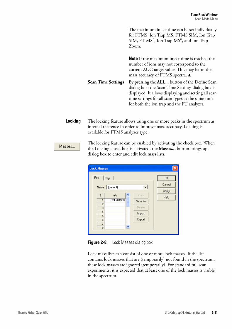
Locking The locking feature allows using one or more peaks in the spectrum as internal reference in order to improve mass accuracy. Locking is available for FTMS analyzer type.
The locking feature can be enabled by activating the check box. When the Locking check box is activated, the Masses... button brings up a dialog box to enter and edit lock mass lists.
Lock mass lists can consist of one or more lock masses. If the list contains lock masses that are (temporarily) not found in the spectrum, these lock masses are ignored (temporarily). For standard full scan experiments, it is expected that at least one of the lock masses is visible in the spectrum.
The maximum inject time can be set individually for FTMS, Ion Trap MS, FTMS SIM, Ion Trap SIM, FT MSn, Ion Trap MSn, and Ion Trap Zoom.
Note If the maximum inject time is reached the number of ions may not correspond to the current AGC target value. This may harm the mass accuracy of FTMS spectra.
Scan Time Settings By pressing the ALL... button of the Define Scan dialog box, the Scan Time Settings dialog box is displayed. It allows displaying and setting all scan time settings for all scan types at the same time for both the ion trap and the FT analyzer.
Figure 2-8. Lock Masses dialog box
Thermo Fisher Scientific LTQ Orbitrap XL Getting Started 2-11
Tune Plus WindowScan Mode Menu
There are two situations where the instrument makes use of a special mode to artificially mix the lock mass into the spectrum:
1. If none of the given lock masses is found in the full spectrum, the instrument tries to improve the abundance of the lock mass by performing additional SIM-injections of the specified lock mass.
2. If the given lock mass cannot be found in the spectrum because the instrument runs in MSn or SIM scan type, the instrument adds the lock mass by using SIM-injections.
This way, lock masses can be used for all FTMS scan types and for varying lock mass abundances. There is no need for user interaction other than specifying a list of reference peak candidates.
See “FT Analyzer Messages” on page A-3 on how to view information about the instruments locking state. See “Using Locking in Automated Runs” on page 5-2 on how to set FTMS locking in Instrument Setup.
MSn Settings The table in this group box allows you to specify the parameters for each segment of an MSn experiment.
Act. Type The Act. Type list box becomes available when you enter a parent mass. It allows you to specify how the ion is activated for fragmentation and has the following options:
• CID (Collision-induced dissociation)
• PQD (Pulsed-Q dissociation)
• HCD (high-energy CID)
HCD is available only as last step in an MSn experiment – it is not be possible to set up an experiment where the first activation method is HCD, and second is CID. If you enter a new step below an HCD experiment, the TunePlus program will change it to a CID experiment.
Act. Q If the Advanced Scan features are enabled, the Activation Q input box is disabled for HCD type fragmentation.
2-12 LTQ Orbitrap XL Getting Started Thermo Fisher Scientific
Tune Plus WindowScan Mode Menu
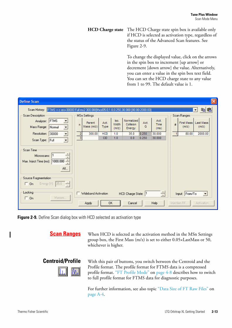
Scan Ranges When HCD is selected as the activation method in the MSn Settings group box, the First Mass (m/z) is set to either 0.05×LastMass or 50, whichever is higher.
Centroid/Profile With this pair of buttons, you switch between the Centroid and the Profile format. The profile format for FTMS data is a compressed profile format. “FT Profile Mode” on page 4-8 describes how to switch to full profile format for FTMS data for diagnostic purposes.
For further information, see also topic “Data Size of FT Raw Files” on page A-4.
HCD Charge state The HCD Charge state spin box is available only if HCD is selected as activation type, regardless of the status of the Advanced Scan features. See Figure 2-9.
To change the displayed value, click on the arrows in the spin box to increment [up arrow] or decrement [down arrow] the value. Alternatively, you can enter a value in the spin box text field. You can set the HCD charge state to any value from 1 to 99. The default value is 1.
Figure 2-9. Define Scan dialog box with HCD selected as activation type
Thermo Fisher Scientific LTQ Orbitrap XL Getting Started 2-13
Tune Plus WindowScan Mode Menu
Positive/Negative With this pair of buttons, you can toggle between positive ion and negative ion polarity. Different FT transfer, storage, and mass calibration parameters are used for the different polarities.
2-14 LTQ Orbitrap XL Getting Started Thermo Fisher Scientific
Tune Plus WindowDisplay Menu
Display Menu This section describes the elements of the Display menu that are different from the LTQ XL.
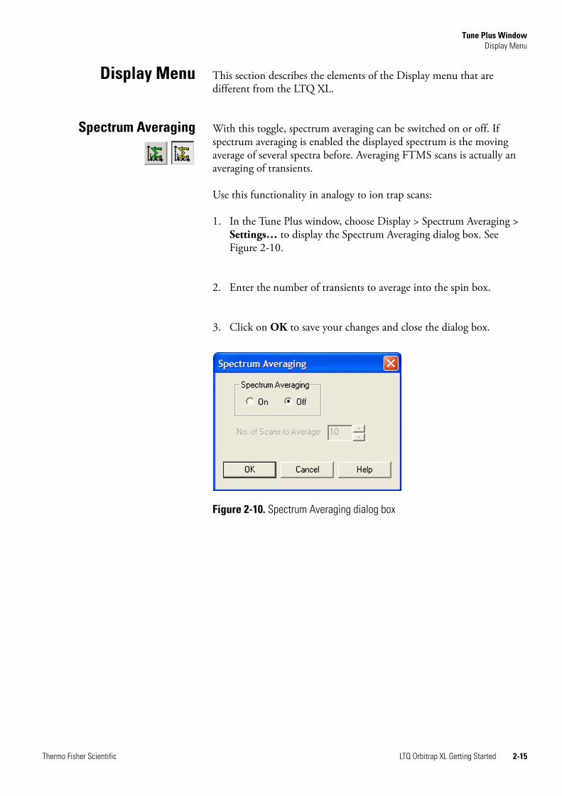
Spectrum Averaging With this toggle, spectrum averaging can be switched on or off. If spectrum averaging is enabled the displayed spectrum is the moving average of several spectra before. Averaging FTMS scans is actually an averaging of transients.
Use this functionality in analogy to ion trap scans:
1. In the Tune Plus window, choose Display > Spectrum Averaging > Settings… to display the Spectrum Averaging dialog box. See Figure 2-10.
2. Enter the number of transients to average into the spin box.
3. Click on OK to save your changes and close the dialog box.
Figure 2-10. Spectrum Averaging dialog box
Thermo Fisher Scientific LTQ Orbitrap XL Getting Started 2-15
Tune Plus WindowSetup Menu
Setup Menu This section describes the elements of the Setup menu that are different from the LTQ XL.
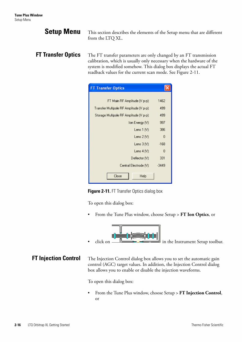
FT Transfer Optics The FT transfer parameters are only changed by an FT transmission calibration, which is usually only necessary when the hardware of the system is modified somehow. This dialog box displays the actual FT readback values for the current scan mode. See Figure 2-11.
To open this dialog box:
• From the Tune Plus window, choose Setup > FT Ion Optics, or
• click on in the Instrument Setup toolbar.
FT Injection Control The Injection Control dialog box allows you to set the automatic gain control (AGC) target values. In addition, the Injection Control dialog box allows you to enable or disable the injection waveforms.
To open this dialog box:
• From the Tune Plus window, choose Setup > FT Injection Control, or
Figure 2-11. FT Transfer Optics dialog box
2-16 LTQ Orbitrap XL Getting Started Thermo Fisher Scientific
Tune Plus WindowSetup Menu
• click on in the Instrument Setup toolbar.
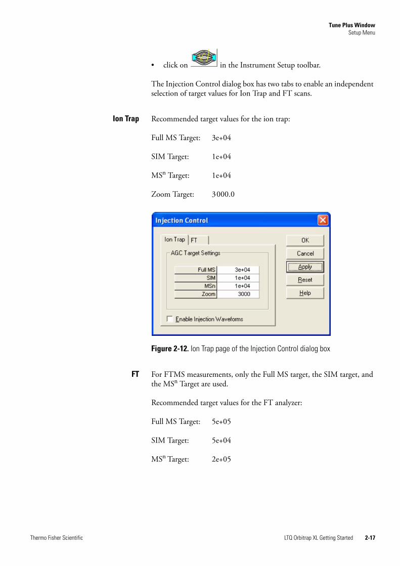
The Injection Control dialog box has two tabs to enable an independent selection of target values for Ion Trap and FT scans.
Ion Trap Recommended target values for the ion trap:
Full MS Target: 3e+04
SIM Target: 1e+04
MSn Target: 1e+04
Zoom Target: 3000.0
FT For FTMS measurements, only the Full MS target, the SIM target, and the MSn Target are used.
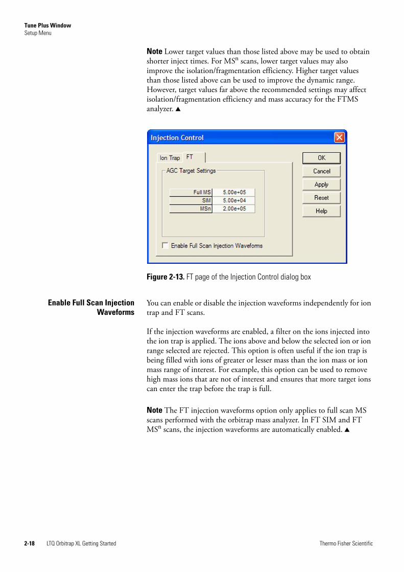
Recommended target values for the FT analyzer:
Full MS Target: 5e+05
SIM Target: 5e+04
MSn Target: 2e+05
Figure 2-12. Ion Trap page of the Injection Control dialog box
Thermo Fisher Scientific LTQ Orbitrap XL Getting Started 2-17
Tune Plus WindowSetup Menu
Note Lower target values than those listed above may be used to obtain shorter inject times. For MSn scans, lower target values may also improve the isolation/fragmentation efficiency. Higher target values than those listed above can be used to improve the dynamic range. However, target values far above the recommended settings may affect isolation/fragmentation efficiency and mass accuracy for the FTMS analyzer.
Enable Full Scan InjectionWaveforms
You can enable or disable the injection waveforms independently for ion trap and FT scans.
If the injection waveforms are enabled, a filter on the ions injected into the ion trap is applied. The ions above and below the selected ion or ion range selected are rejected. This option is often useful if the ion trap is being filled with ions of greater or lesser mass than the ion mass or ion mass range of interest. For example, this option can be used to remove high mass ions that are not of interest and ensures that more target ions can enter the trap before the trap is full.
Note The FT injection waveforms option only applies to full scan MS scans performed with the orbitrap mass analyzer. In FT SIM and FT MSn scans, the injection waveforms are automatically enabled.
Figure 2-13. FT page of the Injection Control dialog box
2-18 LTQ Orbitrap XL Getting Started Thermo Fisher Scientific
Tune Plus WindowSetup Menu
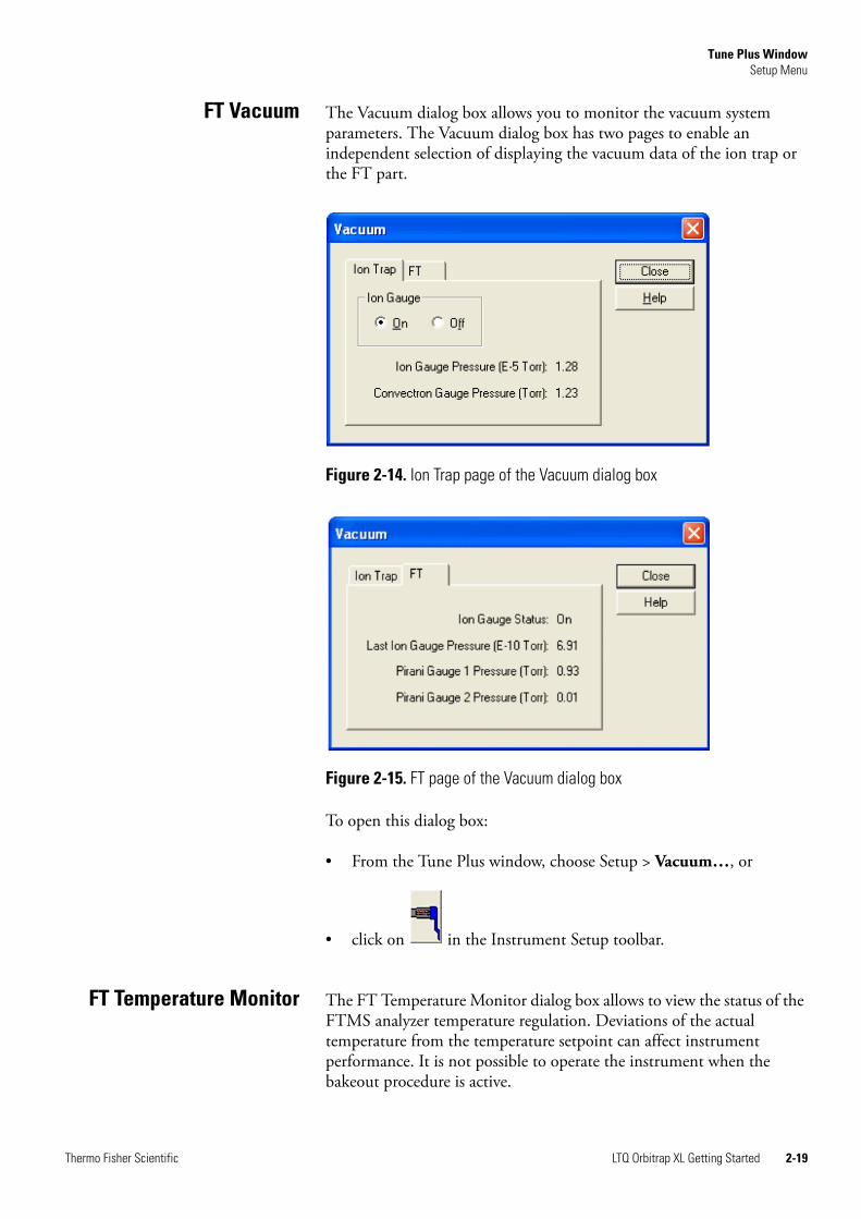
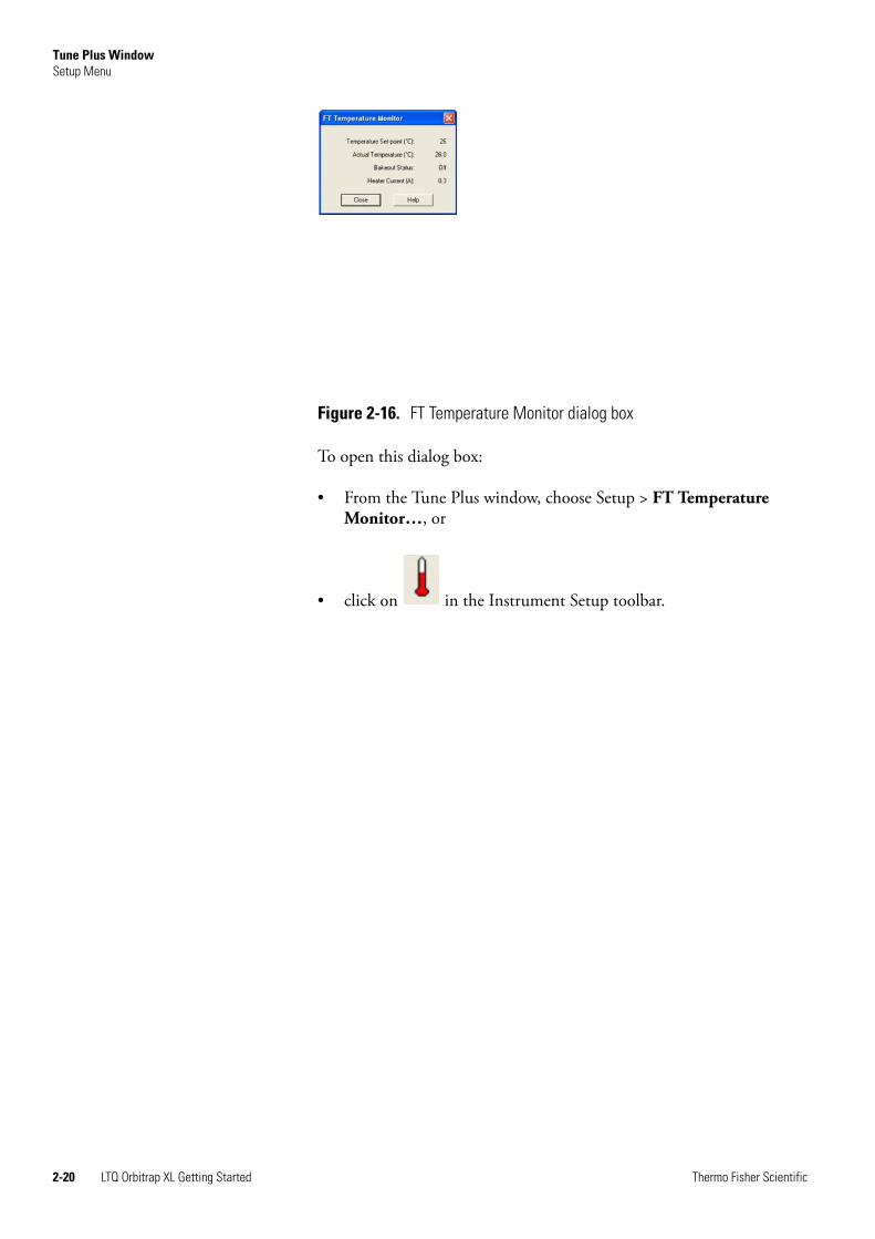
FT Vacuum The Vacuum dialog box allows you to monitor the vacuum system parameters. The Vacuum dialog box has two pages to enable an independent selection of displaying the vacuum data of the ion trap or the FT part.
To open this dialog box:
• From the Tune Plus window, choose Setup > Vacuum…, or
• click on in the Instrument Setup toolbar.
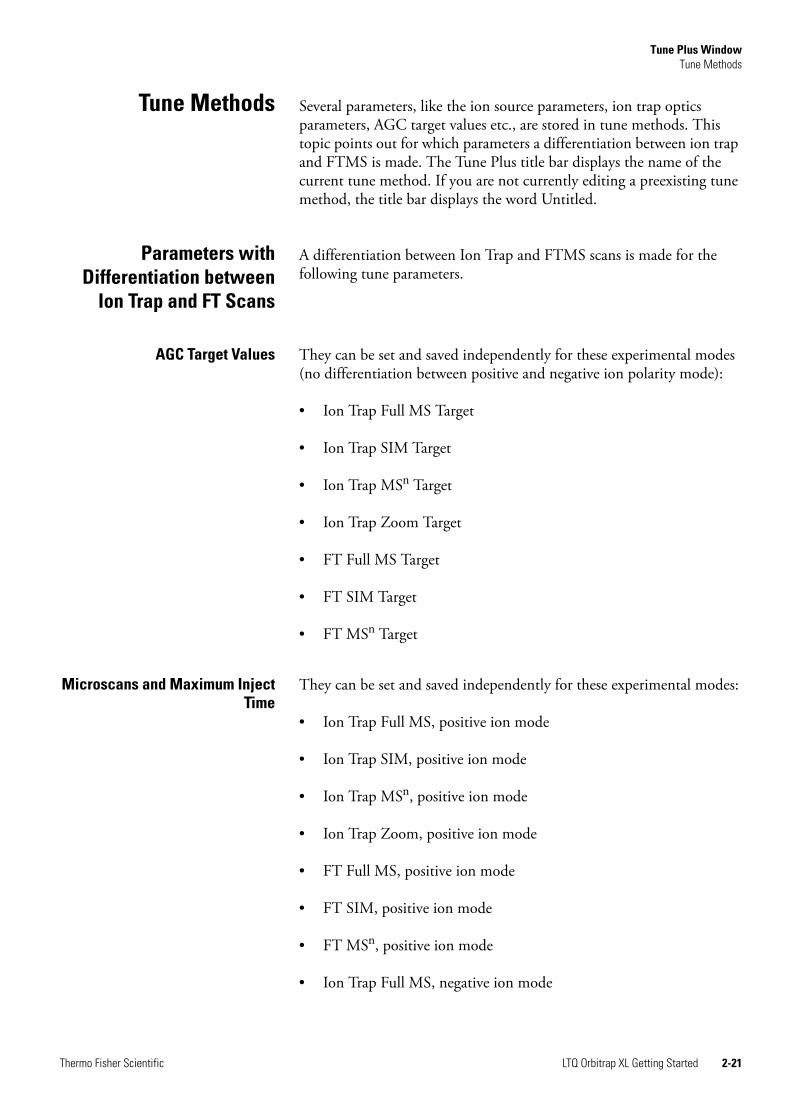
FT Temperature Monitor The FT Temperature Monitor dialog box allows to view the status of the FTMS analyzer temperature regulation. Deviations of the actual temperature from the temperature setpoint can affect instrument performance. It is not possible to operate the instrument when the bakeout procedure is active.
Figure 2-14. Ion Trap page of the Vacuum dialog box
Figure 2-15. FT page of the Vacuum dialog box
Thermo Fisher Scientific LTQ Orbitrap XL Getting Started 2-19
Tune Plus WindowSetup Menu
To open this dialog box:
• From the Tune Plus window, choose Setup > FT Temperature Monitor…, or
• click on in the Instrument Setup toolbar.
Figure 2-16. FT Temperature Monitor dialog box
2-20 LTQ Orbitrap XL Getting Started Thermo Fisher Scientific
Tune Plus WindowTune Methods
Tune Methods Several parameters, like the ion source parameters, ion trap optics parameters, AGC target values etc., are stored in tune methods. This topic points out for which parameters a differentiation between ion trap and FTMS is made. The Tune Plus title bar displays the name of the current tune method. If you are not currently editing a preexisting tune method, the title bar displays the word Untitled.
Parameters withDifferentiation between
Ion Trap and FT Scans
A differentiation between Ion Trap and FTMS scans is made for the following tune parameters.
AGC Target Values They can be set and saved independently for these experimental modes (no differentiation between positive and negative ion polarity mode):
• Ion Trap Full MS Target
• Ion Trap SIM Target
• Ion Trap MSn Target
• Ion Trap Zoom Target
• FT Full MS Target
• FT SIM Target
• FT MSn Target
Microscans and Maximum InjectTime
They can be set and saved independently for these experimental modes:
• Ion Trap Full MS, positive ion mode
• Ion Trap SIM, positive ion mode
• Ion Trap MSn, positive ion mode
• Ion Trap Zoom, positive ion mode
• FT Full MS, positive ion mode
• FT SIM, positive ion mode
• FT MSn, positive ion mode
• Ion Trap Full MS, negative ion mode
Thermo Fisher Scientific LTQ Orbitrap XL Getting Started 2-21
Tune Plus WindowTune Methods
• Ion Trap SIM, negative ion mode
• Ion Trap MSn, negative ion mode
• Ion Trap Zoom, negative ion mode
• FT Full MS, negative ion mode
• FT SIM, negative ion mode
• FT MSn, negative ion mode
Inject Waveform Flags The flag whether the inject waveform is enabled or disabled can be set and saved independently for
• Ion trap scans
• FT full scans.
Parameters withoutDifferentiation between
Ion Trap and FT Scans
No differentiation between Ion Trap and FT scans is made for all ESI parameters, and for all ion source and ion optics parameters.
Parameters not saved in aTunefile
All parameters which can be set in an instrument method are not saved in the tune method. Thus the following parameters are not saved in a tune method:
• Analyzer (Ion Trap or FTMS)
• Mass Range (Low, Normal, or High)
• Scan Rate
• Resolution
• Scan Type (Full, SIM, SRM, CRM)
• Scan Range
• Polarity* (positive or negative)
• Data type* (centroid or profile)
* Only the data format (centroid or profile) and the ion polarity are saved in a tunefile that are set after a new start of TunePlus.
2-22 LTQ Orbitrap XL Getting Started Thermo Fisher Scientific
Chapter 3 Calibrating the Orbitrap XL for FTMS Measurements
This chapter provides procedures to calibrate your LTQ Orbitrap XL for FTMS measurements. It contains the following topics:
• “Preliminary Remarks” on page 3-2
• “Calibration Files and their Backups” on page 3-3
• “Calibration Solutions” on page 3-4
• “Calibration and Tuning of the Ion Trap” on page 3-8
• “Automatic Calibration Page” on page 3-11
• “Semi-Automatic Calibration Page” on page 3-12
• “Check Calibration Page” on page 3-15
• “FT Manual Calibration Page” on page 3-18
Thermo Fisher Scientific LTQ Orbitrap XL Getting Started 3-1
Calibrating the Orbitrap XL for FTMS MeasurementsPreliminary Remarks
Preliminary Remarks There are no specific tune procedures for the FTMS. All FTMS ion transfer and excitation parameters are treated as calibration parameters and are determined in automatic calibration procedures.
In the automatic calibration, the FT transmission calibration and the FTmass calibration are automatically performed for all calibration ranges. In the semi-automatic calibration, it is possible to decide whether the transmission and/or mass calibration are performed only for the positive ion mode, only for the negative ion mode or for both polarities. See topics “Automatic Calibration Page” on page 3-11 and “Semi-Automatic Calibration Page” on page 3-12 for further details.
On the FT Manual calibration page, you can select your own calibration masses for FT ion transmission, storage transmission, and FT mass calibration. See topic “FT Manual Calibration Page” on page 3-18 for further details.
Note It is recommended to use the semi-automatic calibration.
3-2 LTQ Orbitrap XL Getting Started Thermo Fisher Scientific
Calibrating the Orbitrap XL for FTMS MeasurementsCalibration Files and their Backups
Calibration Files andtheir Backups
After a successful or partly successful calibration, the ion trap and FT calibration parameters are saved automatically. All ion trap and FT calibration parameters are stored in the calibration file master.LTQCal, which is located in the folder:
C:\Xcalibur\system\ltq\msx
Backup CurrentCalibration
It is possible to create a backup of the current calibration file manually or by choosing File > Backup Current Calibration in the Tune Plus window. The Backup Current Calibration and Restore Backup Calibration items work by copying the master.LTQCal to user.LTQCal and vice versa.
If a backup calibration user.LTQCal was already generated, the old user.LTQCal will be backed-up to a file named userXYZ.LTQCal. If you perform backup calibrations at regular intervals, then a history of your calibration files is generated in the folder:
C:\Xcalibur\system\ltq\msx
Using the Backup Calibration command regularly allows to return to previous calibrations in case a new calibration is suspected to worsen instrument performance.
Restore BackupCalibration
Upon Restore Backup Calibration, the calibration values saved in user.LTQCal are automatically downloaded to the instrument. Therefore, it is recommended to generate a current backup after a successful calibration.
It is also recommended to use the Restore Backup Calibration command instead of the Restore Factory Calibration command since the backup calibration file is newer than the factory calibration file.
Thermo Fisher Scientific LTQ Orbitrap XL Getting Started 3-3
Calibrating the Orbitrap XL for FTMS MeasurementsCalibration Solutions
Calibration Solutions This section provides information about preparing the calibration solutions for the LTQ Orbitrap XL.
Sollte man die Namen der Loesungen nicht beibehalten. Sonst werden Leute verwirrt die neue und alte Orbitraps - und LTQ FTs - im Labor stehen haben.
LTQ Calibration Solution The LTQ calibration solution consists of caffeine, MRFA, and Ultramark 1621 in an acetonitrile:methanol:water solution containing 1% acetic acid.
Note Vials of caffeine, MRFA, and Ultramark 1621 are included in the API accessory kit. To order more of these compounds, write or call:
Sigma Chemical CompanyP. O. Box 14508St. Louis, Missouri, USA 63178-9916Phone (800) 325-3010 (in the USA or Canada)
(314) 771-3750 (outside the USA or Canada)
Caution AVOID EXPOSURE TO POTENTIALLY HARMFUL MATERIALS.
Always wear protective gloves and safety glasses when you handle solvents or corrosives. Also contain waste streams and use proper ventilation. Refer to your supplier's Material Safety Data Sheet (MSDS) for proper handling of a particular solvent.
To prepare the LTQ calibration solution, use the following procedure:
1. Stock Solution: MRFA
Prepare a 1.5 mL stock solution of 166.7 pmol/µL MRFA in 50:50 methanol:water as follows:
a. Obtain the vial of L-methionyl-arginyl-phenylalanyl-alanine acetate × H2O (MRFA) in your accessory kit. In this form, the MRFA sample has an average molecular weight of 607.7 u. Carefully weigh 3.0 mg of the MRFA sample.
b. Dissolve the MRFA sample in a total volume of 1.0 mL of 50:50 methanol:water. Mix the solution (5.0 nmol/µL) thoroughly.
c. Transfer 50 µL of the 5 nmol/µL solution into a clean polypropylene tube.
d. Add 1.45 mL of 50:50 methanol:water to the tube. Mix this solution (166.7 pmol/µL) thoroughly.
3-4 LTQ Orbitrap XL Getting Started Thermo Fisher Scientific
Calibrating the Orbitrap XL for FTMS MeasurementsCalibration Solutions
e. Label the tube MRFA stock solution and store it in a refrigerator until it is needed.
2. Ultramark 1621 stock solution
Prepare a 10 mL stock solution of 0.1% Ultramark 1621 in acetonitrile as follows:
a. Obtain the vial of Ultramark 1621 in your accessory kit.
b. Using a syringe, measure out 10 µL of Ultramark 1621, and dissolve it in 10 mL of acetonitrile. Mix the solution thoroughly.
c. Label the vial Ultramark 1621 stock solution and store it in a refrigerator until it is needed.
3. LTQ calibration solution
Prepare 10 mL of the LTQ calibration solution as follows:
a. Obtain the 1 mg/mL stock solution of caffeine in 100% methanol that is provided in your accessory kit.
b. Pipet 200 µL of the caffeine stock solution into a clean, dry 10 mL volumetric flask.
c. Pipet 100 µL of the MRFA stock solution into the flask.
d. Pipet 100 µL of the Ultramark 1621 stock solution into the flask.
e. Pipet 100 µL of glacial acetic acid into the flask.
Note Use only glass pipets or stainless steel syringes when measuring glacial acetic acid. Using plastic pipet tips causes contamination of acid stock solutions that can introduce contaminants into the calibration solution.
f. Pipet 5 mL of acetonitrile into the flask.
g. Bring the volume of the solution up to the 10 mL-mark on the flask with 50:50 methanol:water.
h. Mix the calibration solution thoroughly.
i. Transfer the solution to a clean, dry vial.
j. Label the vial LTQ Calibration Solution and store it in a refrigerator until it is needed.
Thermo Fisher Scientific LTQ Orbitrap XL Getting Started 3-5
Calibrating the Orbitrap XL for FTMS MeasurementsCalibration Solutions
LTQ Orbitrap XLCalibration Solution
In contrast to the ion trap calibration, the FT calibration of the LTQ Orbitrap XL requires both positive and negative ions. The LTQ ESI calibration solution does not provide applicable negative ions below m/z 1000. Thus, sodium dodecyl sulfate (gives anion at m/z 265) and sodium taurocholate (gives anion at m/z 514) is added to the LTQ ESI calibration solution to generate the LTQ Orbitrap XL calibration solution. In addition, the ratio of MRFA is increased versus the LTQ calibration solution.
Note Vials of sodium dodecyl sulfate and sodium taurocholate are shipped with the instrument. Refer to the Material Safety Data Sheet (MSDS) for proper handling of these substances. To order more of these compounds, contact Sigma-Aldrich. The product number of sodium dodecyl sulfate is L4509-10G, the product number of sodium taurocholate is T4009-250MG. Note that sodium dodecyl sulfate and sodium taurocholate are not included in the standard LTQ API accessory kit.
Caution AVOID EXPOSURE TO POTENTIALLY HARMFUL MATERIALS.
Always wear protective gloves and safety glasses when you use solvents or corrosives. Also, contain waste streams, and use proper ventilation. Refer to your supplier's Material Safety Data Sheet (MSDS) for proper handling of a particular solvent.
To prepare the LTQ Orbitrap XL calibration solution, use the following procedure:
1. Stock Solution: Sodium Dodecyl Sulfate
a. Obtain the vial of sodium dodecyl sulfate. In this form the sample has an average molecular weight of 288.4 u.
b. Prepare the stock solution of sodium dodecyl sulfate by dissolving 2.88 mg in 10 mL of 50:50 methanol:water.
c. Mix the solution (1.0 nmol/µL) thoroughly.
d. Label the vial Sodium Dodecyl Sulfate stock solution (1 nmol/µL).
2. Stock Solution: Sodium Taurocholate
a. Obtain the vial of sodium taurocholate. In this form the sample has an average molecular weight of 537.7 u.
b. Prepare the stock solution of sodium dodecyl sulfate by dissolving 5.38 mg in 10 mL of 50:50 methanol:water.
c. Mix the solution (1.0 nmol/µL) thoroughly.
3-6 LTQ Orbitrap XL Getting Started Thermo Fisher Scientific
Calibrating the Orbitrap XL for FTMS MeasurementsCalibration Solutions
d. Label the vial Sodium Taurocholate stock solution (1 nmol/µL).
3. Stock Solution: MRFA
To prepare the MRFA stock solution (5.0 nmol/µL or 166.7 pmol/µL in 50:50 methanol:water), refer to step 1 of topic ”LTQ Calibration Solution” above.
4. LTQ Orbitrap XL Calibration Solution
Prepare 10 mL of the LTQ Orbitrap XL calibration solution, as follows:
a. Pipet 10 mL of the standard LTQ ESI calibration solution into a vial.
b. Add 100 µL of the Sodium Dodecyl Sulfate stock solution.
c. Add 100 µL of the Sodium Taurocholate stock solution.
d. Add 6.6 µL of the 5.0 nmol/µL MRFA stock solution or 200 µL of the 166.7 pmol/µL MRFA stock solution, respectively.
e. Mix the solution thoroughly.
f. Label the vial LTQ Orbitrap XL calibration solution and store it in a refrigerator until it is needed.
Applicable CalibrationSolutions for Automatic
Calibration
In an automatic calibration of the LTQ Orbitrap XL, both the ion trap and the FT calibrations (positive and negative ion mode) are performed. Thus for an automatic calibration, the LTQ Orbitrap XL calibration solution has to be used.
Applicable CalibrationSolutions for
Semi-AutomaticCalibration
For the ion trap calibrations, the LTQ ESI calibration solution or the LTQ Orbitrap XL calibration solution can be used. For the FT calibrations of the positive ion mode, the LTQ ESI calibration solution or the LTQ Orbitrap XL calibration solution can be used. For the FT calibrations of the negative ion mode, the LTQ Orbitrap XL calibration solution has to be used. Thus, for a complete FT calibration the LTQ Orbitrap XL calibration has to be used, too.
Applicable CalibrationSolutions for FT Manual
Calibration
Since the FT Manual Calibration page allows using your own calibration masses, it is possible to use custom calibration solution here. However, there are some requirements for the calibration masses. The scan ranges of the instrument need to be covered properly by the given masses.
Thermo Fisher Scientific LTQ Orbitrap XL Getting Started 3-7
Calibrating the Orbitrap XL for FTMS MeasurementsCalibration and Tuning of the Ion Trap
Calibration andTuning of the Ion Trap
This chapter describes the calibration and tuning of the ion trap for FT measurements. It contains the following topics:
• Calibration of the Ion Trap
• Tuning the Ion Trap for Positive Ion Mode
• Tuning the Ion Trap for Negative Ion Mode
Calibration of the Ion Trap To perform an FT calibration, the ion trap has to be successfully calibrated before. It is very important that the electron multiplier gain is correctly calibrated since the AGC prescan is performed in the ion trap. Thus, the electron multiplier gain calibration should be checked before an FT calibration is performed.
Note It is not necessary to use the ESI standard solution to perform a multiplier gain calibration. It is sufficient to use an MRFA solution (for example 5×10⁻⁶ M in 100% methanol, 1% acetic acid).
For the ion trap calibrations, the LTQ ESI calibration solution or the LTQ Orbitrap XL calibration solution can be used.
Tuning the Ion Trap forPositive Ion Mode
For the positive ion mode, it is recommended to perform an automatic tune of m/z 524 at a Full MS Target of 1e4–3e4. Use the LTQ ESI calibration solution or the LTQ Orbitrap XL calibration solution with the following settings in the Define Scan dialog box. See Figure 3-1 on page 3-9.
After the automatic tune, a manual adjustment of the tube lens should be used to get an ion trap spectrum in the scan range 130–2000.
The spectrum should look similar to the spectrum shown in Figure 3-2 on page 3-9. Make sure the peaks at 138, 195, 524, and the highest Ultramark peaks are all present, ideally above 30% of the base peak.
Note The peak at m/z 138 should have a height of more than 10%. Run an automatic ion trap tune on 138 if this signal is too weak.
The inject time should be stable and less than 1 ms (if a Full MS target of 1e4 is used). Do not forget to save the tune method after a successful tuning.
3-8 LTQ Orbitrap XL Getting Started Thermo Fisher Scientific
Calibrating the Orbitrap XL for FTMS MeasurementsCalibration and Tuning of the Ion Trap
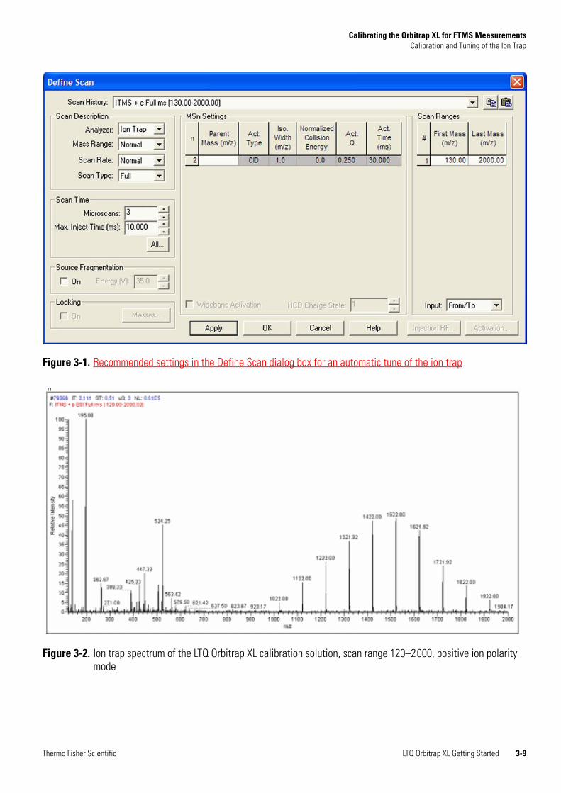
Figure 3-1. Recommended settings in the Define Scan dialog box for an automatic tune of the ion trap
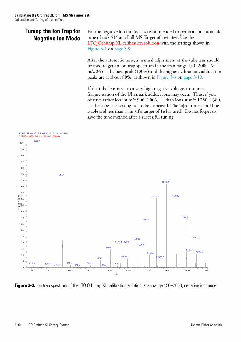
Figure 3-2. Ion trap spectrum of the LTQ Orbitrap XL calibration solution, scan range 120–2000, positive ion polarity mode
Thermo Fisher Scientific LTQ Orbitrap XL Getting Started 3-9
Calibrating the Orbitrap XL for FTMS MeasurementsCalibration and Tuning of the Ion Trap
Tuning the Ion Trap forNegative Ion Mode
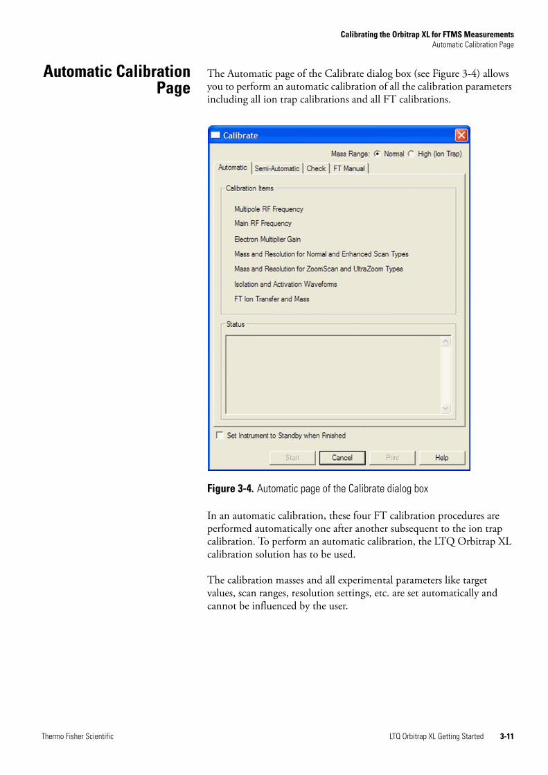
For the negative ion mode, it is recommended to perform an automatic tune of m/z 514 at a Full MS Target of 1e4–3e4. Use the LTQ Orbitrap XL calibration solution with the settings shown in Figure 3-1 on page 3-9.
After the automatic tune, a manual adjustment of the tube lens should be used to get an ion trap spectrum in the scan range 150–2000. At m/z 265 is the base peak (100%) and the highest Ultramark adduct ion peaks are at about 80%, as shown in Figure 3-3 on page 3-10.
If the tube lens is set to a very high negative voltage, in-source fragmentation of the Ultramark adduct ions may occur. Thus, if you observe rather ions at m/z 906, 1006, … than ions at m/z 1280, 1380, … the tube lens setting has to be decreased. The inject time should be stable and less than 1 ms (if a target of 1e4 is used). Do not forget to save the tune method after a successful tuning.
Figure 3-3. Ion trap spectrum of the LTQ Orbitrap XL calibration solution, scan range 150–2000, negative ion mode
#3906 IT: 0.426 ST: 0.83 uS: 5 NL: 8.25E5
F: ITMS - p ESI Full ms [ 150.00-2000.00]
200 400 600 800 1000 1200 1400 1600 1800 2000
m/z
0
5
10
15
20
25
30
35
40
45
50
55
60
65
70
75
80
85
90
95
100
RelativeIntensity
265.2
514.4
1579.6
1679.51479.7
1779.51379.7
1879.51279.8
1206.11106.11306.0
1006.11785.5
1885.51406.0
1179.8 1505.8906.1
596.4210.9 806.1 1079.9379.9 678.3470.1 994.1
3-10 LTQ Orbitrap XL Getting Started Thermo Fisher Scientific
Calibrating the Orbitrap XL for FTMS MeasurementsAutomatic Calibration Page
Automatic CalibrationPage
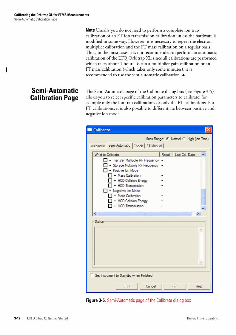
The Automatic page of the Calibrate dialog box (see Figure 3-4) allows you to perform an automatic calibration of all the calibration parameters including all ion trap calibrations and all FT calibrations.
In an automatic calibration, these four FT calibration procedures are performed automatically one after another subsequent to the ion trap calibration. To perform an automatic calibration, the LTQ Orbitrap XL calibration solution has to be used.
The calibration masses and all experimental parameters like target values, scan ranges, resolution settings, etc. are set automatically and cannot be influenced by the user.
Figure 3-4. Automatic page of the Calibrate dialog box
Thermo Fisher Scientific LTQ Orbitrap XL Getting Started 3-11
Calibrating the Orbitrap XL for FTMS MeasurementsSemi-Automatic Calibration Page
Note Usually you do not need to perform a complete ion trap calibration or an FT ion transmission calibration unless the hardware is modified in some way. However, it is necessary to repeat the electron multiplier calibration and the FT mass calibration on a regular basis. Thus, in the most cases it is not recommended to perform an automatic calibration of the LTQ Orbitrap XL since all calibrations are performed which takes about 1 hour. To run a multiplier gain calibration or an FTmass calibration (which takes only some minutes), it is recommended to use the semiautomatic calibration.
Semi-AutomaticCalibration Page
The Semi-Automatic page of the Calibrate dialog box (see Figure 3-5) allows you to select specific calibration parameters to calibrate, for example only the ion trap calibrations or only the FT calibrations. For FT calibrations, it is also possible to differentiate between positive and negative ion mode.
Figure 3-5. Semi-Automatic page of the Calibrate dialog box
3-12 LTQ Orbitrap XL Getting Started Thermo Fisher Scientific
Calibrating the Orbitrap XL for FTMS MeasurementsSemi-Automatic Calibration Page
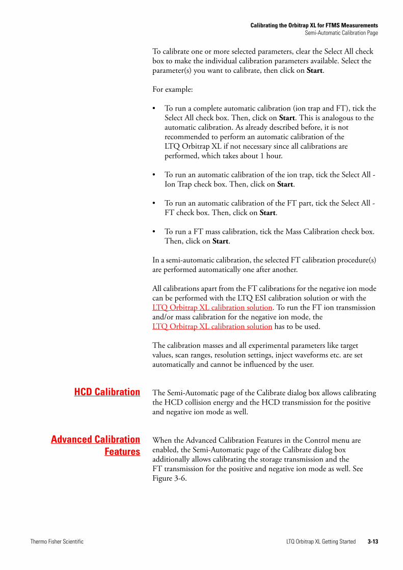
To calibrate one or more selected parameters, clear the Select All check box to make the individual calibration parameters available. Select the parameter(s) you want to calibrate, then click on Start.
For example:
• To run a complete automatic calibration (ion trap and FT), tick the Select All check box. Then, click on Start. This is analogous to the automatic calibration. As already described before, it is not recommended to perform an automatic calibration of the LTQ Orbitrap XL if not necessary since all calibrations are performed, which takes about 1 hour.
• To run an automatic calibration of the ion trap, tick the Select All - Ion Trap check box. Then, click on Start.
• To run an automatic calibration of the FT part, tick the Select All - FT check box. Then, click on Start.
• To run a FT mass calibration, tick the Mass Calibration check box. Then, click on Start.
In a semi-automatic calibration, the selected FT calibration procedure(s) are performed automatically one after another.
All calibrations apart from the FT calibrations for the negative ion mode can be performed with the LTQ ESI calibration solution or with the LTQ Orbitrap XL calibration solution. To run the FT ion transmission and/or mass calibration for the negative ion mode, the LTQ Orbitrap XL calibration solution has to be used.
The calibration masses and all experimental parameters like target values, scan ranges, resolution settings, inject waveforms etc. are set automatically and cannot be influenced by the user.
HCD Calibration The Semi-Automatic page of the Calibrate dialog box allows calibrating the HCD collision energy and the HCD transmission for the positive and negative ion mode as well.
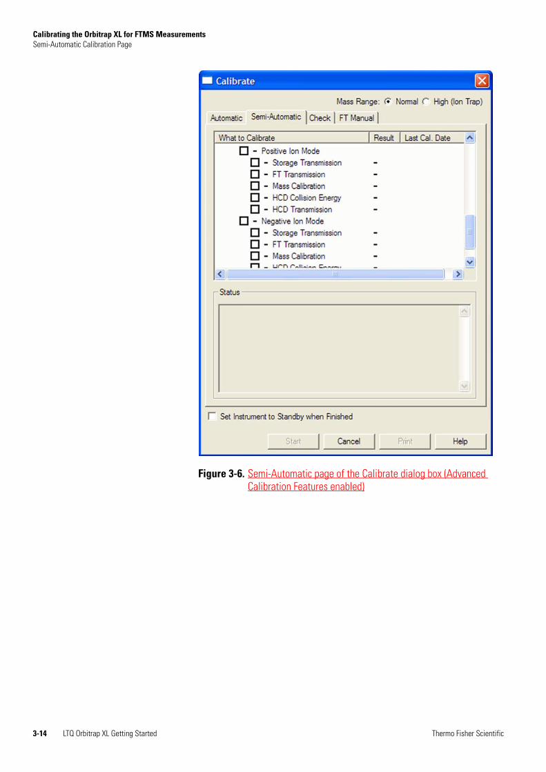
Advanced CalibrationFeatures
When the Advanced Calibration Features in the Control menu are enabled, the Semi-Automatic page of the Calibrate dialog box additionally allows calibrating the storage transmission and the FT transmission for the positive and negative ion mode as well. See Figure 3-6.
Thermo Fisher Scientific LTQ Orbitrap XL Getting Started 3-13
Calibrating the Orbitrap XL for FTMS MeasurementsSemi-Automatic Calibration Page
Figure 3-6. Semi-Automatic page of the Calibrate dialog box (Advanced Calibration Features enabled)
3-14 LTQ Orbitrap XL Getting Started Thermo Fisher Scientific
Calibrating the Orbitrap XL for FTMS MeasurementsCheck Calibration Page
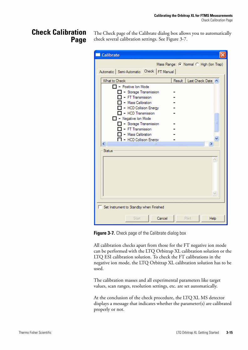
Check CalibrationPage
The Check page of the Calibrate dialog box allows you to automatically check several calibration settings. See Figure 3-7.
All calibration checks apart from those for the FT negative ion mode can be performed with the LTQ Orbitrap XL calibration solution or the LTQ ESI calibration solution. To check the FT calibrations in the negative ion mode, the LTQ Orbitrap XL calibration solution has to be used.
The calibration masses and all experimental parameters like target values, scan ranges, resolution settings, etc. are set automatically.
At the conclusion of the check procedure, the LTQ XL MS detector displays a message that indicates whether the parameter(s) are calibrated properly or not.
Figure 3-7. Check page of the Calibrate dialog box
Thermo Fisher Scientific LTQ Orbitrap XL Getting Started 3-15
Calibrating the Orbitrap XL for FTMS MeasurementsCheck Calibration Page
Using the Check page of the Calibrate dialog box, you can select the following parameters:
Select All This check box allows you to specify whether or not to check all of the calibration parameters. To check all calibration parameters, select the Select All check box. In this case, all ion trap calibration parameters and all FT calibration parameters are checked. You can also check each calibration parameter individually. To make the individual calibration parameters available, clear the Select All check box.
Select All Ion Trap This check box allows you to specify whether or not to check the calibration of the linear ion trap parameters only.
Select All-FT This check box allows you to specify whether or not to check the calibration of the Orbitrap ion transfer optics and mass analyzer only.
Transfer Multipole RF Frequency
This check box allows you to specify whether or not to check the frequency of the RF voltage of the transfer multipole in the FT transfer ion optics.
Storage Multipole RF Frequency
This check box allows you to specify whether or not to check the frequency of the RF voltage of the storage multipole in the FT transfer ion optics.
Positive Ion Mode This check box allows you to specify whether or not to check the FT ion transmission calibration and FT mass calibration for the positive ion mode.
Negative Ion Mode This check box allows you to specify whether or not to check the FT ion transmission calibration and FT mass calibration for the negative ion mode.
Storage Transmission This check box allows you to specify whether or not to check the ion storage transmission calibration. The storage transmission is checked by transferring ions form the ion trap to the ion storage device and backward, then scanning in the ion trap. The FT storage transmission calibration can be checked for the positive and negative ion mode independently.
3-16 LTQ Orbitrap XL Getting Started Thermo Fisher Scientific
Calibrating the Orbitrap XL for FTMS MeasurementsCheck Calibration Page
The Last Check Date readback column gives the date of the last successful check for each item. If a check is performed that fails, the last successful check date still appears in the Last Check Date readback column. The last successful check continues to be in effect in the instrument. However, the result column will show a red x mark indicating that the current attempt check has failed or was aborted.
FT Transmission This check box allows you to specify whether or not to check the FT ion transmission calibration. The ion transmission from the ion trap to the Orbitrap is checked by means of the calibration masses in SIM experiments at different AGC target values. The FT transmission calibration can be checked for the positive and negative ion mode independently.
Mass Calibration This check box allows you to specify whether or not to check the mass calibration of the Orbitrap mass analyzer. In this check, the current mass calibration is checked, i.e it is a check of the external mass calibration. The FTmass calibration can be checked for the positive and negative ion mode independently.
HCD Collision Energy This check box allows you to specify whether or not to check the HCD collision energy.
HCD Transmission This check box allows you to specify whether or not to check the HCD transmission.
Thermo Fisher Scientific LTQ Orbitrap XL Getting Started 3-17
Calibrating the Orbitrap XL for FTMS MeasurementsFT Manual Calibration Page
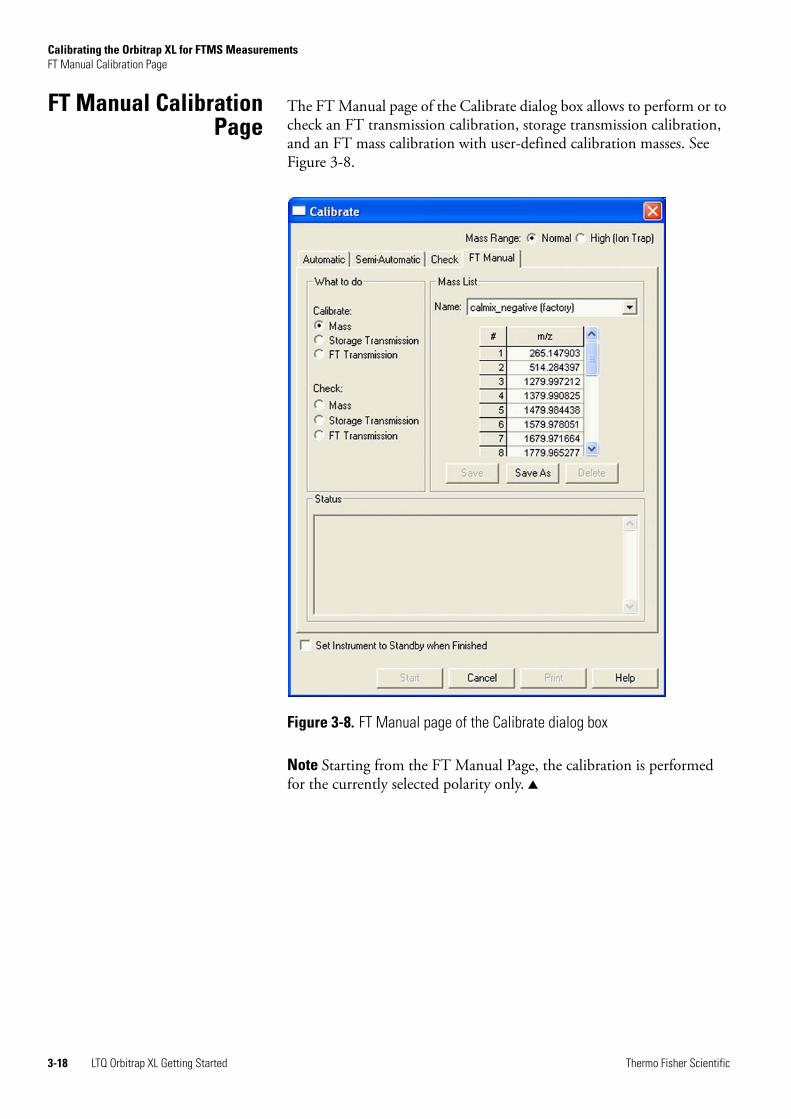
FT Manual CalibrationPage
The FT Manual page of the Calibrate dialog box allows to perform or to check an FT transmission calibration, storage transmission calibration, and an FT mass calibration with user-defined calibration masses. See Figure 3-8.
Note Starting from the FT Manual Page, the calibration is performed for the currently selected polarity only.
Figure 3-8. FT Manual page of the Calibrate dialog box
3-18 LTQ Orbitrap XL Getting Started Thermo Fisher Scientific
Calibrating the Orbitrap XL for FTMS MeasurementsFT Manual Calibration Page
Mass List Group Box The calibration masses for the manual calibration can be defined in the corresponding mass list on the FT Manual page of the Calibration dialog box. Mass lists can be imported and exported by means of the Instrument Configuration page, see further details in Chapter 6: “Instrument Configuration”.
Note Ensure that you use calibration masses of sufficient accuracy (sub ppm).
Factory-Supplied Mass Lists There are also two factory supplied mass lists, calmix_positive (factory) and calmix_negative (factory). They contain the exact masses of all main ion peaks, which should appear if the LTQ Orbitrap XL calibration solution is used in positive or negative ion mode, respectively.
Name This list box lists the names of the factory supplied and user created mass lists.
Mass List This table lists the mass-to-charge ratios of the ions that you are using to calibrate the orbitrap mass analyzer. You can select an existing mass list in the Name list box, or you can create or modify a mass list by clicking on it and editing the entries in the Mass List table.
Note Ensure that you use calibration masses of sufficient accuracy (sub ppm).
Save Click on Save to save the mass list with the name that is selected in the Name list box.
Save As Click on Save As a to save the mass list with a new name.
Delete Click on Delete to delete the mass list that is selected in the Name list box.
Thermo Fisher Scientific LTQ Orbitrap XL Getting Started 3-19
Calibrating the Orbitrap XL for FTMS MeasurementsFT Manual Calibration Page
3-20 LTQ Orbitrap XL Getting Started Thermo Fisher Scientific
Chapter 4 Performing Diagnostics/Checks
This chapter describes several diagnostic procedures for the LTQ Orbitrap XL. It contains the following topics:
• “System Evaluation Procedures” on page 4-2
• “Toggles” on page 4-6
• “Set Device” on page 4-10
• “Display Settings” on page 4-12
Thermo Fisher Scientific LTQ Orbitrap XL Getting Started 4-1
Performing Diagnostics/ChecksSystem Evaluation Procedures
System EvaluationProcedures
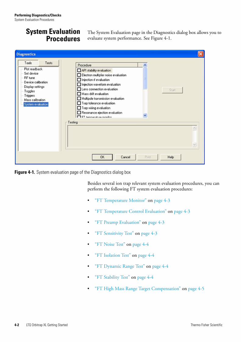
The System Evaluation page in the Diagnostics dialog box allows you to evaluate system performance. See Figure 4-1.
Besides several ion trap relevant system evaluation procedures, you can perform the following FT system evaluation procedures:
• “FT Temperature Monitor” on page 4-3
• “FT Temperature Control Evaluation” on page 4-3
• “FT Preamp Evaluation” on page 4-3
• “FT Sensitivity Test” on page 4-3
• “FT Noise Test” on page 4-4
• “FT Isolation Test” on page 4-4
• “FT Dynamic Range Test” on page 4-4
• “FT Stability Test” on page 4-4
• “FT High Mass Range Target Compensation” on page 4-5
Figure 4-1. System evaluation page of the Diagnostics dialog box
4-2 LTQ Orbitrap XL Getting Started Thermo Fisher Scientific
Performing Diagnostics/ChecksSystem Evaluation Procedures
FT Temperature Monitor External mass accuracy of the orbitrap detector depends on a stable temperature of the analyzer and the electronic components. This evaluation plots a history of the temperature regulation results to the graph view, see “Graph View” on page 2-5.
FT Temperature ControlEvaluation
This evaluation procedure allows examining temperature regulation behavior of the instrument by intentionally driving temperatures to extreme values.
Note The evaluation will usually take more than 12 hours where no measurements can be done. After stopping the evaluation, the instrument needs to stabilize temperatures for several hours before high mass accuracy measurements can be started.
FT Preamp Evaluation This evaluation allows checking the basic FTMS analyzer signal detection path. The instrument needs to run in FTMS analyzer mode. It is recommended to switch to diagnostic transient view, see “FT Include Transients” on page 4-7.
During the evaluation, the preamp input protection switches are activated with a period of 100 ms. This switching can be observed as periodic incidences in the transient if the electronic signal path is operational.
FT Sensitivity Test The FT sensitivity test is only applicable for an infusion experiment with Reserpine. The test assumes that a Reserpine solution of 5×10⁻⁹ M (100% methanol, 1% acetic acid) is used. The following test are performed one after another:
1. SIM of m/z 609.28 using the ion trap as analyzer and an AGC target of 2e+03.
2. SIM of m/z 609.28 using the orbitrap detector as analyzer and an AGC target of 5e+03.
3. SIM of m/z 609.28 using the orbitrap detector as analyzer and an AGC target of 5e+04.
4. MS/MS of m/z 609.28 using the orbitrap detector and an AGC target of 5e+04.
Thermo Fisher Scientific LTQ Orbitrap XL Getting Started 4-3
Performing Diagnostics/ChecksSystem Evaluation Procedures
The test fails
1. if the inject time which is necessary to reach the selected AGC target value is too high;
2. if the ratio of the reserpine signal to the overall signal inside the SIM window is too low;
3. if the transmission from the ion trap to the orbitrap detector is too low, or
4. if the intensity of the product ions of reserpine is too low.
FT Noise Test This test determines resistant noise peaks in the selected scan range. In this test ions are “switched off ” automatically. At the conclusion of the FT noise test, a list of resistant noise peaks is displayed in the Testing text.
FT Isolation Test This test is only applicable for an infusion experiment with a solution containing MRFA, for example the standard LTQ calibration solution or a MRFA alone solution (for example 5×10⁻⁶ M in 100% methanol/water, 1% acetic acid). This test is analogous to the “Check of the ion isolation waveform” on the Check page of the Calibrate dialog box. Here, the isolation of m/z 525.3 is performed at a target of 2000 and analyzed by the ion trap. In contrast to this, the FT isolation test is performed at higher targets and uses the FT analyzer. Thus this test determines the maximum AGC target value that allows performing a unit isolation of m/z 525.3 at the presence of m/z 524.3 and 526.3.
FT Dynamic Range Test This test is only applicable for an infusion experiment with a solution containing MRFA, for example the standard LTQ calibration solution or a MRFA alone solution (for example 5×10⁻⁶ M in 100% methanol/water, 1% acetic acid). This test determines the signal-to-noise ratio of an isolated MRFA signal.
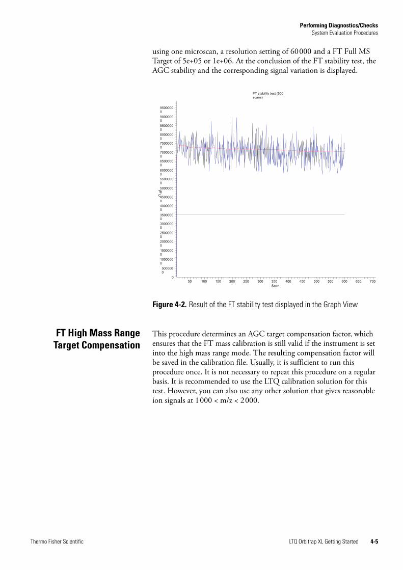
FT Stability Test This test is applicable for an infusion experiment with any sample solution. This test procedure checks the stability of the FT TIC (total ion current) detected in the selected scan range by means of 600 scans. In principle, the test can be performed at any experimental conditions. It is recommended, however, to perform this test in Full scan mode
4-4 LTQ Orbitrap XL Getting Started Thermo Fisher Scientific
Performing Diagnostics/ChecksSystem Evaluation Procedures
using one microscan, a resolution setting of 60000 and a FT Full MS Target of 5e+05 or 1e+06. At the conclusion of the FT stability test, the AGC stability and the corresponding signal variation is displayed.
FT High Mass RangeTarget Compensation
This procedure determines an AGC target compensation factor, which ensures that the FT mass calibration is still valid if the instrument is set into the high mass range mode. The resulting compensation factor will be saved in the calibration file. Usually, it is sufficient to run this procedure once. It is not necessary to repeat this procedure on a regular basis. It is recommended to use the LTQ calibration solution for this test. However, you can also use any other solution that gives reasonable ion signals at 1000 < m/z < 2000.
Figure 4-2. Result of the FT stability test displayed in the Graph View
FT stability test (600 scans)
50 100 150 200 250 300 350 400 450 500 550 600 650 700
Scan
0
5000000
10000000
15000000
20000000
25000000
30000000
35000000
40000000
45000000
50000000
55000000
60000000
65000000
70000000
75000000
80000000
85000000
90000000
95000000
TIC
Thermo Fisher Scientific LTQ Orbitrap XL Getting Started 4-5
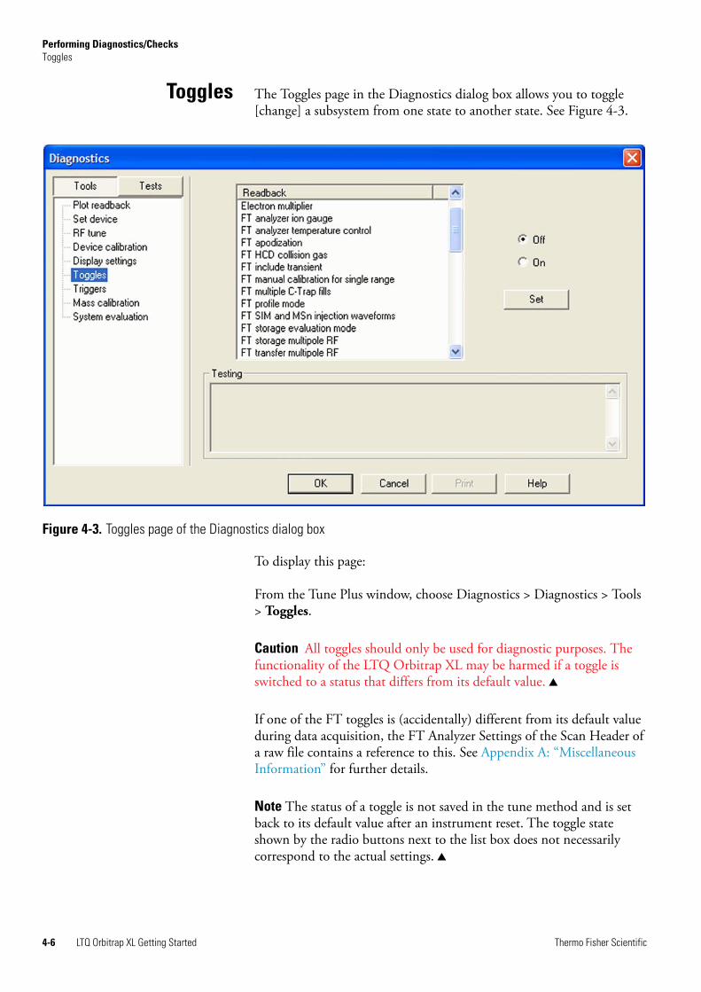
Performing Diagnostics/ChecksToggles
Toggles The Toggles page in the Diagnostics dialog box allows you to toggle [change] a subsystem from one state to another state. See Figure 4-3.
To display this page:
From the Tune Plus window, choose Diagnostics > Diagnostics > Tools > Toggles.
Caution All toggles should only be used for diagnostic purposes. The functionality of the LTQ Orbitrap XL may be harmed if a toggle is switched to a status that differs from its default value.
If one of the FT toggles is (accidentally) different from its default value during data acquisition, the FT Analyzer Settings of the Scan Header of a raw file contains a reference to this. See Appendix A: “Miscellaneous Information” for further details.
Note The status of a toggle is not saved in the tune method and is set back to its default value after an instrument reset. The toggle state shown by the radio buttons next to the list box does not necessarily correspond to the actual settings.
Figure 4-3. Toggles page of the Diagnostics dialog box
4-6 LTQ Orbitrap XL Getting Started Thermo Fisher Scientific
Performing Diagnostics/ChecksToggles
FT Analyzer Ion Gauge With this toggle, the ion gauge for the FT analyzer vacuum can be disabled manually for diagnostic purposes. The default setting is enabled.
FT Analyzer TemperatureControl
With this toggle, the FT analyzer temperature control regulation electronics can be disabled for diagnostic purposes. The default setting is enabled.
FT Apodization With this toggle, the apodization can be switched on or off. The default setting is On.
FT HCD Collision Gas With this toggle, the HCD collision gas can be switched on or off. The default setting is On.
FT Include Transients If this toggle is on, it is possible to display transients in the Spectrum view by choosing Show FT Transient in the shortcut menu of the Spectrum view. The menu is displayed when you right-click anywhere on that page. See topic “Spectrum View” on page 2-3 for further details.
Note A transient view is only possible if profile (instead of centroid) is chosen as data format.
During transient display in Spectrum view, the x-coordinate is misleadingly labeled with m/z instead of milliseconds. The default setting is Off.
Note It is not possible to acquire transients into an Xcalibur raw file.
FT Storage Multipole RF This toggle can be used to switch the FT storage multipole RF on or off. The default setting is On. If the multipole RF is switched on, the corresponding blue diagnostic LED of the ion optic supply board should be on (indicating that the RF1 generator is switched on). See the LTQ XL Hardware Manual for further details.
FT Transfer Multipole RF This toggle can be used to switch the FT transfer multipole RF on or off. The default setting is On. If the multipole RF is switched on, the corresponding blue diagnostic LED of the ion optic supply board should be on (indicating that the RF2 generator is switched on). See the LTQ XL Hardware Manual for further details.
Thermo Fisher Scientific LTQ Orbitrap XL Getting Started 4-7
Performing Diagnostics/ChecksToggles
FT Manual Calibration forSingle Range
This toggle can be used to influence the behavior of the FT manual calibration procedures, refer to “FT Manual Calibration Page” on page 3-18. In the default behavior, the FT manual calibration procedures calibrate the whole scan mass range for the actual polarity.
In order to be able to use nonstandard calibration substances that cover a limited mass range only, advanced users may enable this toggle. With this toggle enabled, there is no check for mass range coverage of reference mass lists. Instead, the instrument stays in the chosen mass range and calibrates this range only. With this toggle enabled, the user is responsible to cover the whole mass range needed, possibly by calibrating manually in several steps with different substances. If the performed FT manual calibration is not suitable for the scan settings used in an FTMS analyzer data acquisition, the scan header of a raw data file contains a reference to this. See Chapter A: “Miscellaneous Information” for further details.
FT Multiple C-Trap Fills With this toggle you can allow the C-Trap to accommodate multiple ion injections from the linear trap (and HCD collision cell?). Variation of collision gases and collision energies allow creating mixed ion populations. Subsequently, the ions are injected as a single pulse into the orbitrap. The default setting is On (enabled).
Gibt es eine maximale Anzahl an Fills? Wie wird so eine Messung mit mehreren Fuellung aufgesetzt?
FT Profile Mode With this toggle you can select whether the FT profile mode corresponds to a Full Profile format or to a Reduced Profile format. It is recommended to use the Reduced Profile Mode for data acquisition since the data size of the raw file is significantly decreased by using the Reduced Profile. The default setting is Reduced. For further information, see also topic “Data Size of FT Raw Files” on page A-4.
FT SIM and MSn InjectionWaveforms
Usually, for FT SIM and FT MSn scans, the injection waveforms are automatically enabled. It is not possible to change this setting in the Injection Control dialog box. By means of this toggle, it is possible to disable or enable the injection waveforms manually for diagnostic purposes. The default setting is On.
FT View Frequency If this toggle is switched on, the FT spectrum is shown as a frequency spectrum. If the system is on and the FT is chosen as analyzer, the frequency spectrum is displayed in the Spectrum view. The default setting is Off.
4-8 LTQ Orbitrap XL Getting Started Thermo Fisher Scientific
Performing Diagnostics/ChecksToggles
Note The x-coordinate is misleadingly labeled with m/z instead of kHz.
This toggle is for diagnostic purposes only. Therefore, it is not possible to acquire frequency spectra.
FT Zero Offset If this toggle is switched on, an offset is added to the spectrum. This enables to view the full noise band. The default setting is Off, if the Reduced Profile format is used. The setting is On, if the Full Profile format is used.
Thermo Fisher Scientific LTQ Orbitrap XL Getting Started 4-9
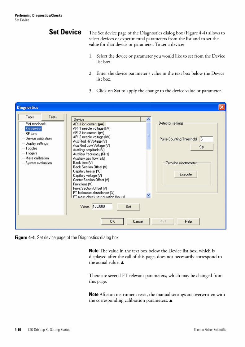
Performing Diagnostics/ChecksSet Device
Set Device The Set device page of the Diagnostics dialog box (Figure 4-4) allows to select devices or experimental parameters from the list and to set the value for that device or parameter. To set a device:
1. Select the device or parameter you would like to set from the Device list box.
2. Enter the device parameter's value in the text box below the Device list box.
3. Click on Set to apply the change to the device value or parameter.
Note The value in the text box below the Device list box, which is displayed after the call of this page, does not necessarily correspond to the actual value.
There are several FT relevant parameters, which may be changed from this page.
Note After an instrument reset, the manual settings are overwritten with the corresponding calibration parameters.
Figure 4-4. Set device page of the Diagnostics dialog box
4-10 LTQ Orbitrap XL Getting Started Thermo Fisher Scientific
Performing Diagnostics/ChecksSet Device
Caution Changing the instrument settings can harm the functionality of the LTQ Orbitrap XL, especially if followed by saving the calibration parameters (manually or at conclusion of a calibration procedure). Thus, this option should only be used by very advanced users.
FT Lockmass Abundance This device allows changing the target value of an injected lock mass relative to the actual FT scan target value. The recommended default is 10 percent. Also refer to “Locking” on page 2-11.
FT Mass Check TestDuration
This device allows changing the duration of FT Manual mass calibration checks, see “FT Manual Calibration Page” on page 3-18. By changing this value, a long-term mass stability evaluation can be run. The default behavior of the FT manual mass calibration check is to perform 100 scans checking the mass accuracy. The test duration may be extended to up to 72 hours. The default behavior can be restored by setting the duration to zero. If the duration is set between two and 24 hours, the FT manual mass calibration check will specially control the syringe pump in order to allow running long-term test with a single syringe filling. For durations above 24 hours, it is assumed that an external syringe pump is used.
Setting new FT TransferOptics Parameters
There are two set device items that can be used to override the FT optics values. These values are originally determined during instrument calibration and set automatically. Overriding calibration values will influence instrument performance and should only be done for diagnostic purposes.
Note If you have changed FT transfer optics settings, it is recommended to perform a full FT instrument calibration afterwards to assure good instrument performance.
Thermo Fisher Scientific LTQ Orbitrap XL Getting Started 4-11
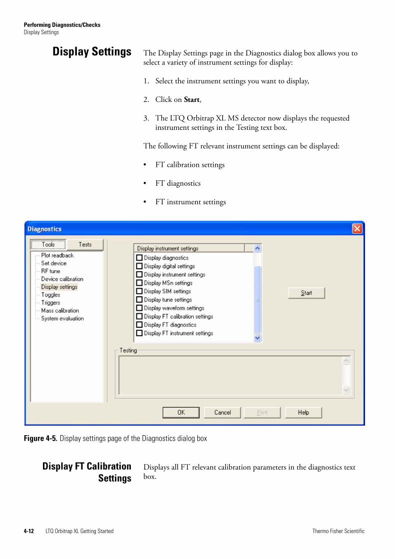
Performing Diagnostics/ChecksDisplay Settings
Display Settings The Display Settings page in the Diagnostics dialog box allows you to select a variety of instrument settings for display:
1. Select the instrument settings you want to display,
2. Click on Start,
3. The LTQ Orbitrap XL MS detector now displays the requested instrument settings in the Testing text box.
The following FT relevant instrument settings can be displayed:
• FT calibration settings
• FT diagnostics
• FT instrument settings
Display FT CalibrationSettings
Displays all FT relevant calibration parameters in the diagnostics text box.
Figure 4-5. Display settings page of the Diagnostics dialog box
4-12 LTQ Orbitrap XL Getting Started Thermo Fisher Scientific
Performing Diagnostics/ChecksDisplay Settings
Display FT Diagnostics Displays current diagnostic readback values of the FT electronic boards.
Display FT InstrumentSettings
Displays the current values of those FT instrument settings that depend on the scan range and ion polarity mode and can be changed manually on the Set Device page of the Diagnostics dialog box.
Thermo Fisher Scientific LTQ Orbitrap XL Getting Started 4-13

Performing Diagnostics/ChecksDisplay Settings
4-14 LTQ Orbitrap XL Getting Started Thermo Fisher Scientific
Chapter 5 Instrument Setup
This chapter takes a look at the “Locking” feature in automated runs and describes the FT relevant topics of the data dependent settings in the Instrument Setup. It contains the following topics:
• “Using Locking in Automated Runs” on page 5-2
• “Data Dependent Settings” on page 5-3
Thermo Fisher Scientific LTQ Orbitrap XL Getting Started 5-1
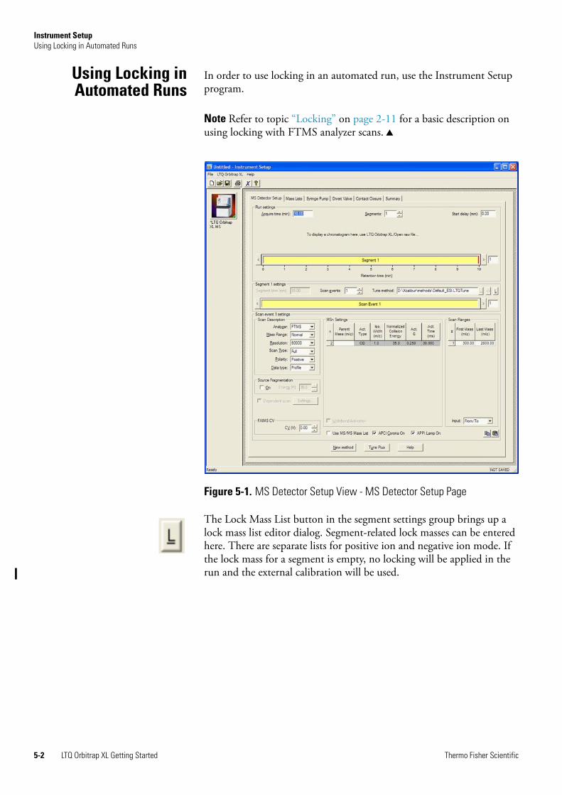
Instrument SetupUsing Locking in Automated Runs
Using Locking inAutomated Runs
In order to use locking in an automated run, use the Instrument Setup program.
Note Refer to topic “Locking” on page 2-11 for a basic description on using locking with FTMS analyzer scans.
The Lock Mass List button in the segment settings group brings up a lock mass list editor dialog. Segment-related lock masses can be entered here. There are separate lists for positive ion and negative ion mode. If the lock mass for a segment is empty, no locking will be applied in the run and the external calibration will be used.
Figure 5-1. MS Detector Setup View - MS Detector Setup Page
5-2 LTQ Orbitrap XL Getting Started Thermo Fisher Scientific
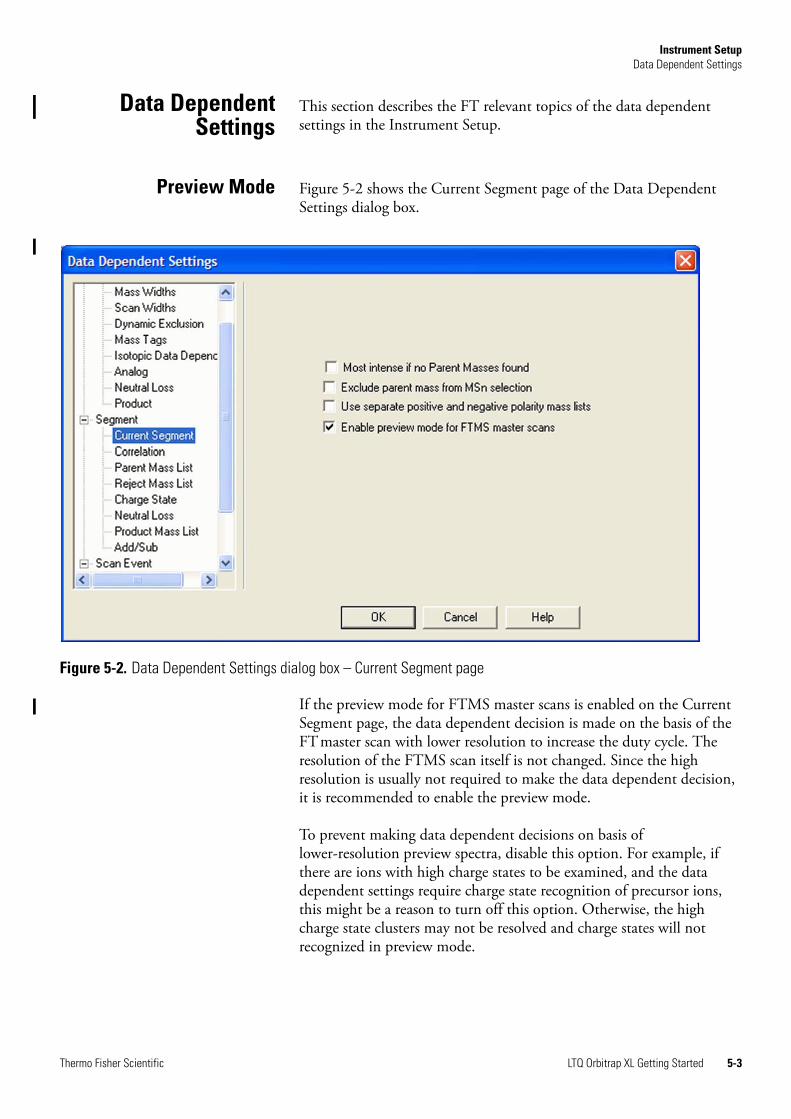
Instrument SetupData Dependent Settings
Data DependentSettings
This section describes the FT relevant topics of the data dependent settings in the Instrument Setup.
Preview Mode Figure 5-2 shows the Current Segment page of the Data Dependent Settings dialog box.
If the preview mode for FTMS master scans is enabled on the Current Segment page, the data dependent decision is made on the basis of the FTmaster scan with lower resolution to increase the duty cycle. The resolution of the FTMS scan itself is not changed. Since the high resolution is usually not required to make the data dependent decision, it is recommended to enable the preview mode.
To prevent making data dependent decisions on basis of lower-resolution preview spectra, disable this option. For example, if there are ions with high charge states to be examined, and the data dependent settings require charge state recognition of precursor ions, this might be a reason to turn off this option. Otherwise, the high charge state clusters may not be resolved and charge states will not recognized in preview mode.
Figure 5-2. Data Dependent Settings dialog box – Current Segment page
Thermo Fisher Scientific LTQ Orbitrap XL Getting Started 5-3
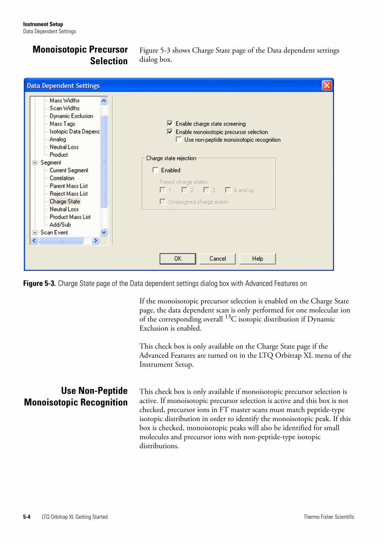
Instrument SetupData Dependent Settings
Monoisotopic PrecursorSelection
Figure 5-3 shows Charge State page of the Data dependent settings dialog box.
If the monoisotopic precursor selection is enabled on the Charge State page, the data dependent scan is only performed for one molecular ion of the corresponding overall 13C isotopic distribution if Dynamic Exclusion is enabled.
This check box is only available on the Charge State page if the Advanced Features are turned on in the LTQ Orbitrap XL menu of the Instrument Setup.
Use Non-PeptideMonoisotopic Recognition
This check box is only available if monoisotopic precursor selection is active. If monoisotopic precursor selection is active and this box is not checked, precursor ions in FT master scans must match peptide-type isotopic distribution in order to identify the monoisotopic peak. If this box is checked, monoisotopic peaks will also be identified for small molecules and precursor ions with non-peptide-type isotopic distributions.
Figure 5-3. Charge State page of the Data dependent settings dialog box with Advanced Features on
5-4 LTQ Orbitrap XL Getting Started Thermo Fisher Scientific
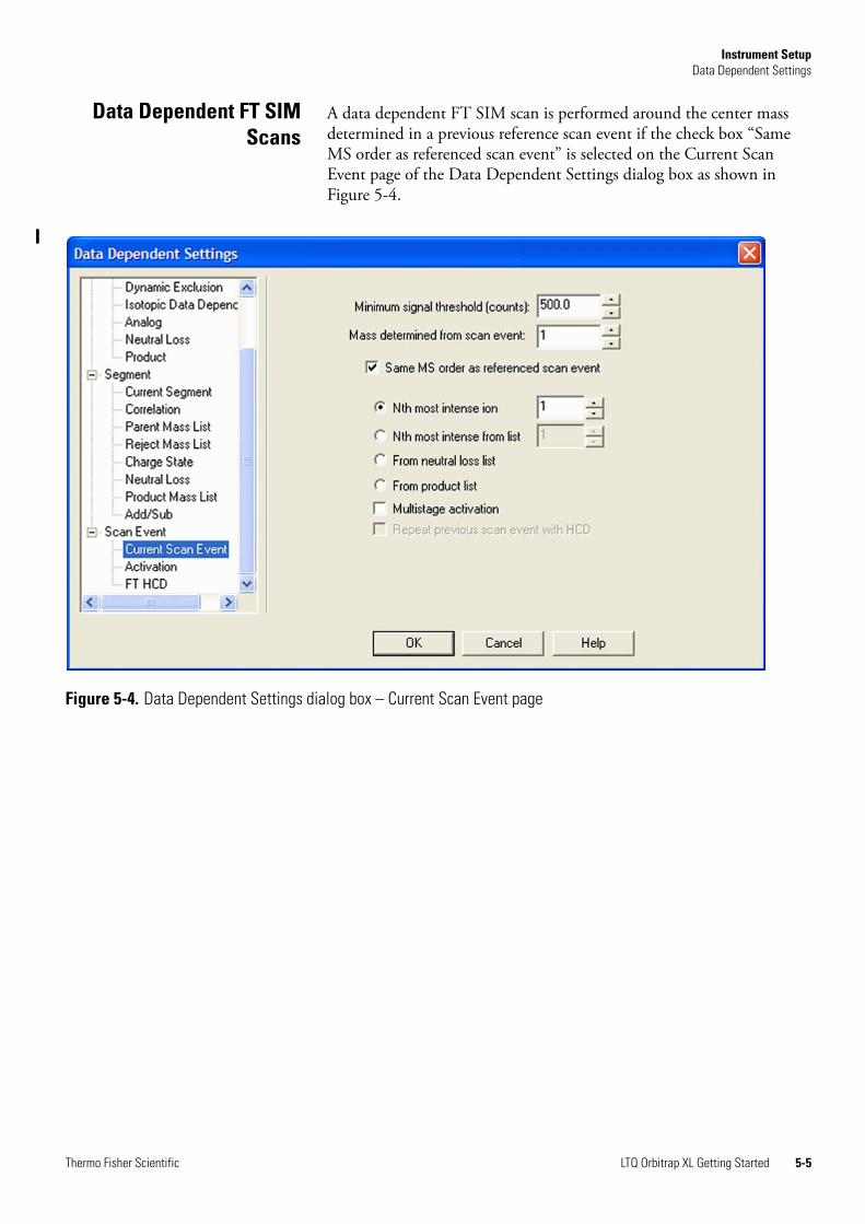
Instrument SetupData Dependent Settings
Data Dependent FT SIMScans
A data dependent FT SIM scan is performed around the center mass determined in a previous reference scan event if the check box “Same MS order as referenced scan event” is selected on the Current Scan Event page of the Data Dependent Settings dialog box as shown in Figure 5-4.
Figure 5-4. Data Dependent Settings dialog box – Current Scan Event page
Thermo Fisher Scientific LTQ Orbitrap XL Getting Started 5-5
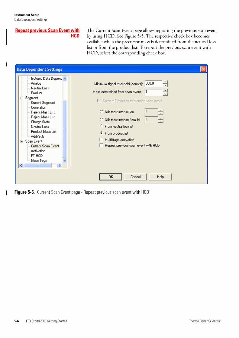
Instrument SetupData Dependent Settings
Repeat previous Scan Event withHCD
The Current Scan Event page allows repeating the previous scan event by using HCD. See Figure 5-5. The respective check box becomes available when the precursor mass is determined from the neutral loss list or from the product list. To repeat the previous scan event with HCD, select the corresponding check box.
Figure 5-5. Current Scan Event page - Repeat previous scan event with HCD
5-6 LTQ Orbitrap XL Getting Started Thermo Fisher Scientific
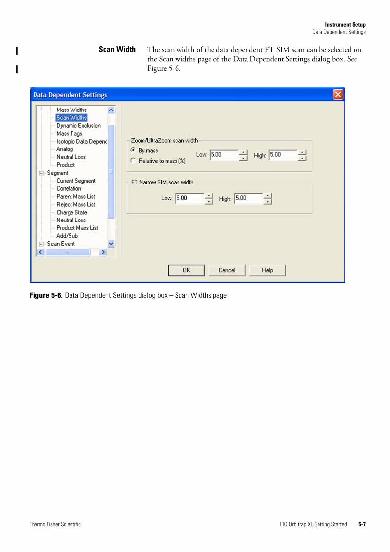
Instrument SetupData Dependent Settings
Scan Width The scan width of the data dependent FT SIM scan can be selected on the Scan widths page of the Data Dependent Settings dialog box. See Figure 5-6.
Figure 5-6. Data Dependent Settings dialog box – Scan Widths page
Thermo Fisher Scientific LTQ Orbitrap XL Getting Started 5-7
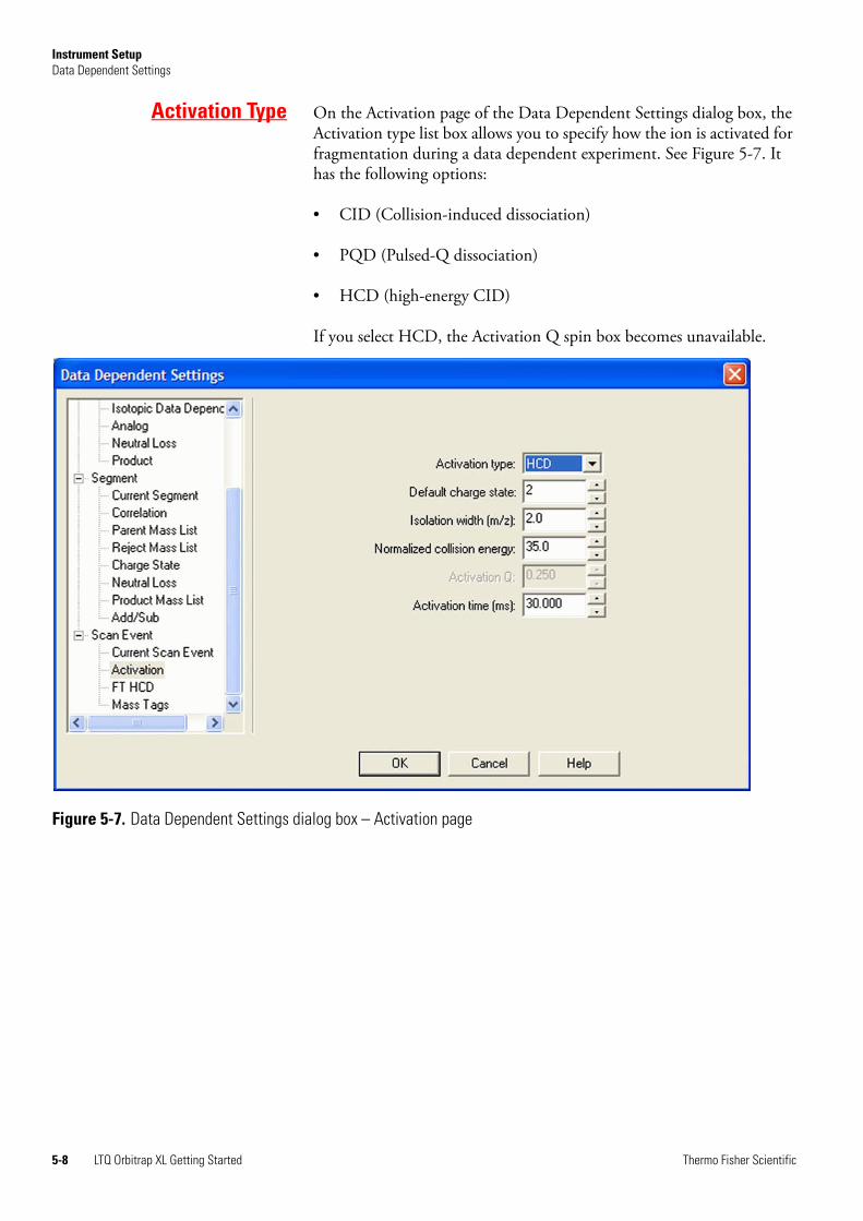
Instrument SetupData Dependent Settings
Activation Type On the Activation page of the Data Dependent Settings dialog box, the Activation type list box allows you to specify how the ion is activated for fragmentation during a data dependent experiment. See Figure 5-7. It has the following options:
• CID (Collision-induced dissociation)
• PQD (Pulsed-Q dissociation)
• HCD (high-energy CID)
If you select HCD, the Activation Q spin box becomes unavailable.
Figure 5-7. Data Dependent Settings dialog box – Activation page
5-8 LTQ Orbitrap XL Getting Started Thermo Fisher Scientific
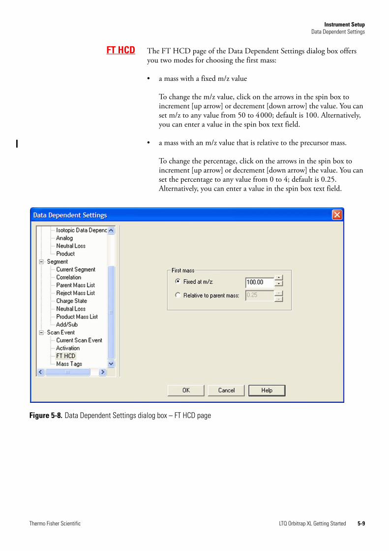
Instrument SetupData Dependent Settings
FT HCD The FT HCD page of the Data Dependent Settings dialog box offers you two modes for choosing the first mass:
• a mass with a fixed m/z value
To change the m/z value, click on the arrows in the spin box to increment [up arrow] or decrement [down arrow] the value. You can set m/z to any value from 50 to 4000; default is 100. Alternatively, you can enter a value in the spin box text field.
• a mass with an m/z value that is relative to the precursor mass.
To change the percentage, click on the arrows in the spin box to increment [up arrow] or decrement [down arrow] the value. You can set the percentage to any value from 0 to 4; default is 0.25. Alternatively, you can enter a value in the spin box text field.
Figure 5-8. Data Dependent Settings dialog box – FT HCD page
Thermo Fisher Scientific LTQ Orbitrap XL Getting Started 5-9
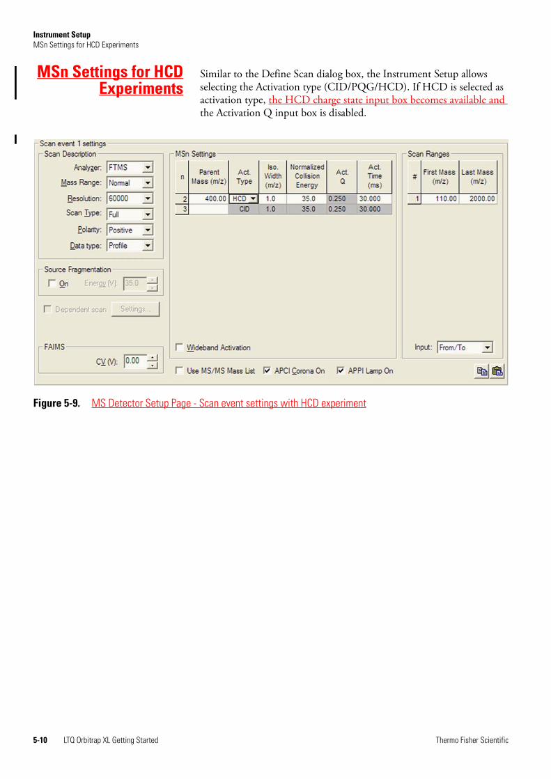
Instrument SetupMSn Settings for HCD Experiments
MSn Settings for HCDExperiments
Similar to the Define Scan dialog box, the Instrument Setup allows selecting the Activation type (CID/PQG/HCD). If HCD is selected as activation type, the HCD charge state input box becomes available and the Activation Q input box is disabled.
Figure 5-9. MS Detector Setup Page - Scan event settings with HCD experiment
5-10 LTQ Orbitrap XL Getting Started Thermo Fisher Scientific
Chapter 6 Instrument Configuration
This chapter gives instructions on how to configure your instrument. It contains the following topics:
• “Starting Instrument Configuration” on page 6-2
• “FT Settings Page” on page 6-3
• “FT Mass Lists Page” on page 6-4
Thermo Fisher Scientific LTQ Orbitrap XL Getting Started 6-1
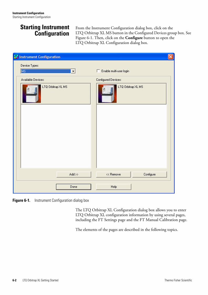
Instrument ConfigurationStarting Instrument Configuration
Starting InstrumentConfiguration
From the Instrument Configuration dialog box, click on the LTQ Orbitrap XL MS button in the Configured Devices group box. See Figure 6-1. Then, click on the Configure button to open the LTQ Orbitrap XL Configuration dialog box.
The LTQ Orbitrap XL Configuration dialog box allows you to enter LTQ Orbitrap XL configuration information by using several pages, including the FT Settings page and the FT Manual Calibration page.
The elements of the pages are described in the following topics.
Figure 6-1. Instrument Configuration dialog box
6-2 LTQ Orbitrap XL Getting Started Thermo Fisher Scientific
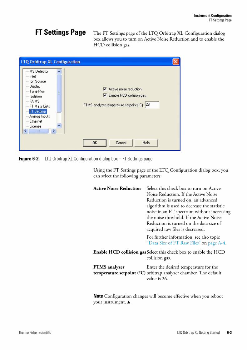
Instrument ConfigurationFT Settings Page
FT Settings Page The FT Settings page of the LTQ Orbitrap XL Configuration dialog box allows you to turn on Active Noise Reduction and to enable the HCD collision gas.
Using the FT Settings page of the LTQ Configuration dialog box, you can select the following parameters:
Note Configuration changes will become effective when you reboot your instrument.
Figure 6-2. LTQ Orbitrap XL Configuration dialog box – FT Settings page
Active Noise Reduction Select this check box to turn on Active Noise Reduction. If the Active Noise Reduction is turned on, an advanced algorithm is used to decrease the statistic noise in an FT spectrum without increasing the noise threshold. If the Active Noise Reduction is turned on the data size of acquired raw files is decreased.For further information, see also topic “Data Size of FT Raw Files” on page A-4.
Enable HCD collision gasSelect this check box to enable the HCD collision gas.
FTMS analyzer temperature setpoint (°C)
Enter the desired temperature for the orbitrap analyzer chamber. The default value is 26.
Thermo Fisher Scientific LTQ Orbitrap XL Getting Started 6-3
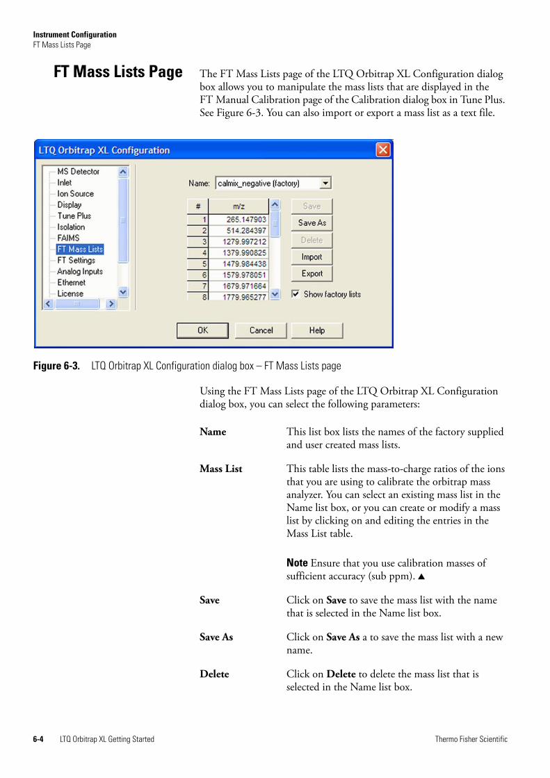
Instrument ConfigurationFT Mass Lists Page
FT Mass Lists Page The FT Mass Lists page of the LTQ Orbitrap XL Configuration dialog box allows you to manipulate the mass lists that are displayed in the FT Manual Calibration page of the Calibration dialog box in Tune Plus. See Figure 6-3. You can also import or export a mass list as a text file.
Using the FT Mass Lists page of the LTQ Orbitrap XL Configuration dialog box, you can select the following parameters:
Figure 6-3. LTQ Orbitrap XL Configuration dialog box – FT Mass Lists page
Name This list box lists the names of the factory supplied and user created mass lists.
Mass List This table lists the mass-to-charge ratios of the ions that you are using to calibrate the orbitrap mass analyzer. You can select an existing mass list in the Name list box, or you can create or modify a mass list by clicking on and editing the entries in the Mass List table.
Note Ensure that you use calibration masses of sufficient accuracy (sub ppm).
Save Click on Save to save the mass list with the name that is selected in the Name list box.
Save As Click on Save As a to save the mass list with a new name.
Delete Click on Delete to delete the mass list that is selected in the Name list box.
6-4 LTQ Orbitrap XL Getting Started Thermo Fisher Scientific
Instrument ConfigurationFT Mass Lists Page
Import Click on Import to import a mass list that is a text file.
Export Click on Export to export a mass list to a text file.
Show Factory Lists Select this check box if you want to show the factory calibration mass lists in Tune Plus.
Thermo Fisher Scientific LTQ Orbitrap XL Getting Started 6-5

Appendix A Miscellaneous Information
This appendix contains supplemental information for the previous chapters. It contains the following topics:
• “FT Analyzer Information in Scan Header” on page A-2
• “Data Size of FT Raw Files” on page A-4
Thermo Fisher Scientific LTQ Orbitrap XL Getting Started A-1
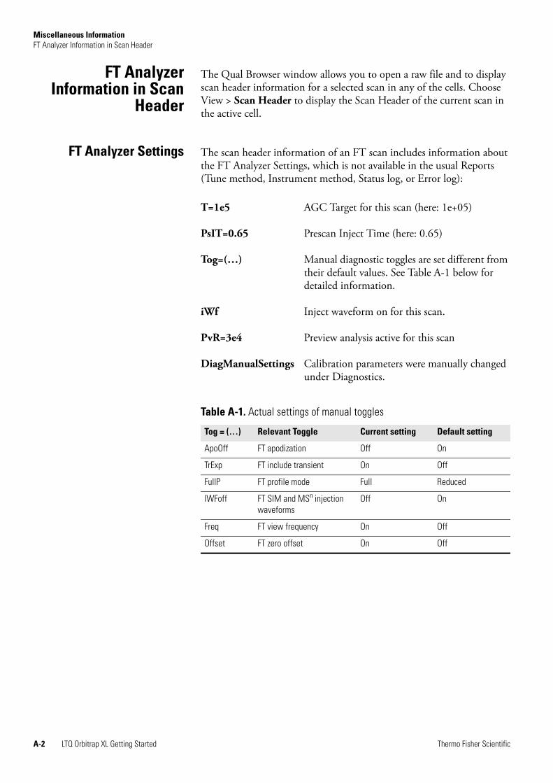
Miscellaneous InformationFT Analyzer Information in Scan Header
FT AnalyzerInformation in Scan
Header
The Qual Browser window allows you to open a raw file and to display scan header information for a selected scan in any of the cells. Choose View > Scan Header to display the Scan Header of the current scan in the active cell.
FT Analyzer Settings The scan header information of an FT scan includes information about the FT Analyzer Settings, which is not available in the usual Reports (Tune method, Instrument method, Status log, or Error log):
T=1e5 AGC Target for this scan (here: 1e+05)
PsIT=0.65 Prescan Inject Time (here: 0.65)
Tog=(…) Manual diagnostic toggles are set different from their default values. See Table A-1 below for detailed information.
iWf Inject waveform on for this scan.
PvR=3e4 Preview analysis active for this scan
DiagManualSettings Calibration parameters were manually changed under Diagnostics.
Table A-1. Actual settings of manual toggles
Tog = (…) Relevant Toggle Current setting Default setting
ApoOff FT apodization Off On
TrExp FT include transient On Off
FullP FT profile mode Full Reduced
IWFoff FT SIM and MSn injection waveforms
Off On
Freq FT view frequency On Off
Offset FT zero offset On Off
A-2 LTQ Orbitrap XL Getting Started Thermo Fisher Scientific

Miscellaneous InformationFT Analyzer Information in Scan Header
FT Analyzer Messages The scan header of an FT scan includes also so-called FT Analyzer Messages:
Ufill=0.45 Maximum ion time reached. Here: the real number of ions is only ~45% of the target value.
MCal=4d Last mass calibration for this scan range is several days old (here: 4)
Est=0x24 Machine-readable result message for post-processing tools
DAC=0.98 FT transient measurement near saturation, this might result in spectral harmonics (typically target value too high)
TCal=[195..] This is a hint that the current scan range settings for the FT analyzer are outside the calibrated storage/transfer mass range. Transfer parameters are extrapolated.
Lock=(inj524.3,1/1,+3ppm) Information about lock mass settings, extra SIM injection of lock mass ions, number of identified lock masses in the spectrum, and deviation of corrected (locked) masses compared to the external calibration.
Stable=15min Shows the elapsed stabilization time of the FTMS analyzer high voltage electronics after last off state or polarity switch. For best external mass accuracies, it is required to let the FTMS analyzer high voltage electronics stabilize before performing an acquisition or mass calibration.
Thermo Fisher Scientific LTQ Orbitrap XL Getting Started A-3
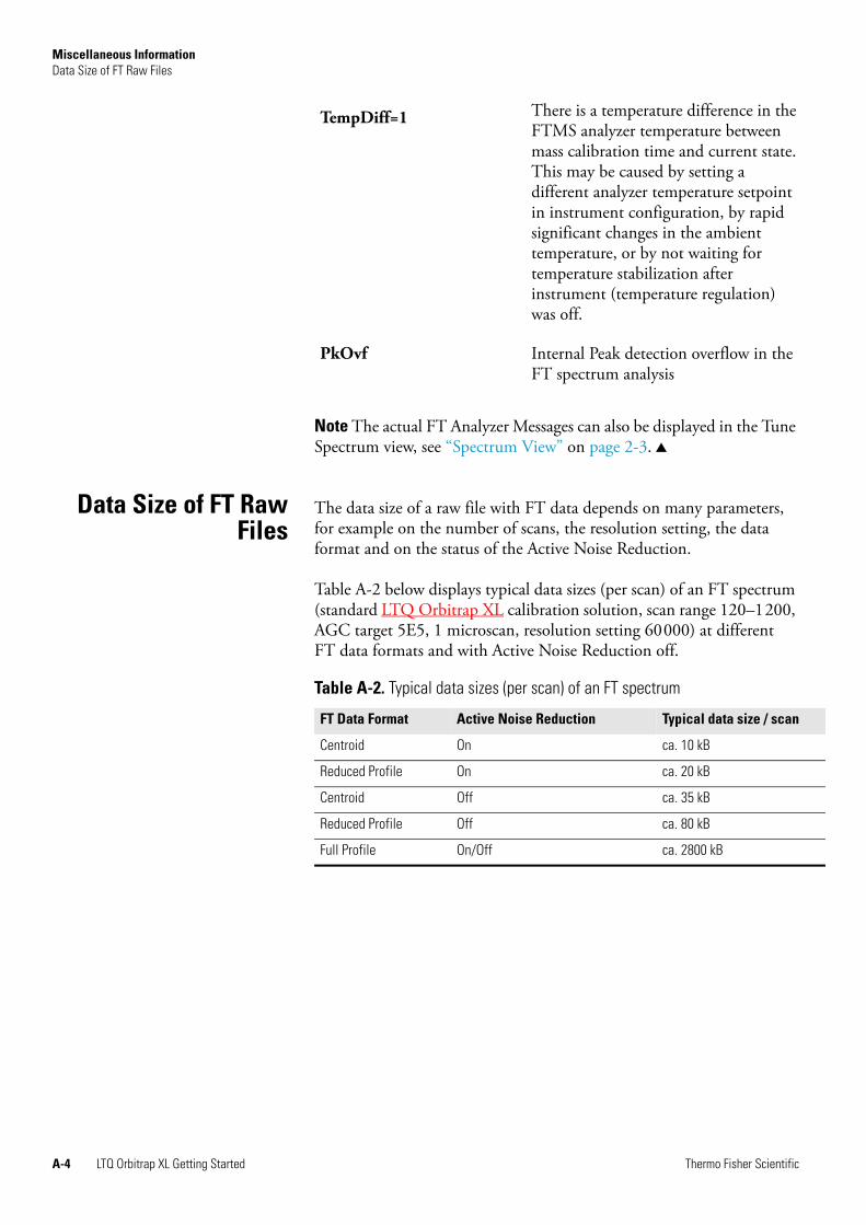
Miscellaneous InformationData Size of FT Raw Files
Note The actual FT Analyzer Messages can also be displayed in the Tune Spectrum view, see “Spectrum View” on page 2-3.
Data Size of FT RawFiles
The data size of a raw file with FT data depends on many parameters, for example on the number of scans, the resolution setting, the data format and on the status of the Active Noise Reduction.
Table A-2 below displays typical data sizes (per scan) of an FT spectrum (standard LTQ Orbitrap XL calibration solution, scan range 120–1200, AGC target 5E5, 1 microscan, resolution setting 60000) at different FT data formats and with Active Noise Reduction off.
TempDiff=1 There is a temperature difference in the FTMS analyzer temperature between mass calibration time and current state. This may be caused by setting a different analyzer temperature setpoint in instrument configuration, by rapid significant changes in the ambient temperature, or by not waiting for temperature stabilization after instrument (temperature regulation) was off.
PkOvf Internal Peak detection overflow in the FT spectrum analysis
Table A-2. Typical data sizes (per scan) of an FT spectrum
FT Data Format Active Noise Reduction Typical data size / scan
Centroid On ca. 10 kB
Reduced Profile On ca. 20 kB
Centroid Off ca. 35 kB
Reduced Profile Off ca. 80 kB
Full Profile On/Off ca. 2800 kB
A-4 LTQ Orbitrap XL Getting Started Thermo Fisher Scientific
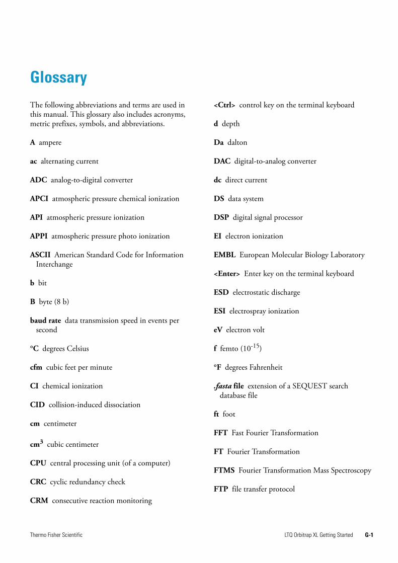
Glossary
The following abbreviations and terms are used in this manual. This glossary also includes acronyms, metric prefixes, symbols, and abbreviations.
A ampere
ac alternating current
ADC analog-to-digital converter
APCI atmospheric pressure chemical ionization
API atmospheric pressure ionization
APPI atmospheric pressure photo ionization
ASCII American Standard Code for Information Interchange
b bit
B byte (8 b)
baud rate data transmission speed in events per second
°C degrees Celsius
cfm cubic feet per minute
CI chemical ionization
CID collision-induced dissociation
cm centimeter
cm3 cubic centimeter
CPU central processing unit (of a computer)
CRC cyclic redundancy check
CRM consecutive reaction monitoring
<Ctrl> control key on the terminal keyboard
d depth
Da dalton
DAC digital-to-analog converter
dc direct current
DS data system
DSP digital signal processor
EI electron ionization
EMBL European Molecular Biology Laboratory
<Enter> Enter key on the terminal keyboard
ESD electrostatic discharge
ESI electrospray ionization
eV electron volt
f femto (10-15)
°F degrees Fahrenheit
.fasta file extension of a SEQUEST search database file
ft foot
FFT Fast Fourier Transformation
FT Fourier Transformation
FTMS Fourier Transformation Mass Spectroscopy
FTP file transfer protocol
Thermo Fisher Scientific LTQ Orbitrap XL Getting Started G-1
Glossary: FWHM
FWHM full width at half maximum
g gram
G Gauss; giga (109)
GC gas chromatograph; gas chromatography
GC/MS gas chromatograph / mass spectrometer
GUI graphical user interface
h hour
h height
HCD Higher Energy Collision Induced Dissociation
HPLC high-performance liquid chromatograph
HV high voltage
Hz hertz (cycles per second)
ICIS™ Interactive Chemical Information System
ICL™ Instrument Control Language™
ID inside diameter
IEC International Electrotechnical Commission
IEEE Institute of Electrical and Electronics Engineers
in inch
I/O input/output
k kilo (103, 1000)
K kilo (210, 1024)
KEGG Kyoto Encyclopedia of Genes and Genomes
kg kilogram
l length
L liter
lb pound
LC liquid chromatograph; liquid chromatography
LC/MS liquid chromatograph / mass spectrometer
LED light-emitting diode
µ micro (10-6)
m meter
m milli (10-3)
M mega (106)
M+ molecular ion
MALDI matrix-assisted laser desorption/ionization
MB Megabyte (1048576 bytes)
MH+ protonated molecular ion
min minute
mL milliliter
mm millimeter
MRFA A peptide with the amino acid sequence methionine–arginine–phenylalanine–alanine.
MS mass spectrometer; mass spectrometry
MS MSn power: where n = 1
MSDS Material Safety Data Sheet
MS/MS MSn power: where n = 2
MSn MSn power: where n = 1 through 10
m/z mass-to-charge ratio
G-2 LTQ Orbitrap XL Getting Started Thermo Fisher Scientific
Glossary: n
n nano (10-9)
NCBI National Center for Biotechnology Information (USA)
NIST National Institute of Standards and Technology (USA)
OD outside diameter
OT orbitrap
Ω ohm
p pico (10-12)
Pa pascal
PCB printed circuit board
P/N part number
ppm parts per million
RAM random access memory
RF radio frequency
RMS root mean square
ROM read-only memory
s second
SIM selected ion monitoring
SRM selected reaction monitoring
TCP/IP transmission control protocol / Internet protocol
TIC total ion current
Torr torr
TWA time weighted average
u atomic mass unit
V volt
V ac volts alternating current
V dc volts direct current
vol volume
w width
W watt
Thermo Fisher Scientific LTQ Orbitrap XL Getting Started G-3

Index
Aaccuracy, of calibration masses 6-4Activation page 5-8Activation Q 2-12, 5-8Active Noise Reduction 6-3, A-4actual settings, of manual toggles A-2Advanced Calibration Features 2-8, 3-13Advanced Features 5-4advanced scan features 2-9AGC 2-10stability 4-5target compensation factor 4-5target values 2-10–2-11, 2-16, 2-21
analyzer temperature control 4-7analyzer type 2-9analyzer vacuum 4-7API accessory kit 3-4, 3-6apodization 4-7automated run 5-2automatic calibration 3-2, 3-7, 3-11automatic gain control (AGC) 2-16Automatic page, of the Calibrate dialog box 3-11automatic tune, recommended settings 3-9
Bbakeout procedure 2-19
CCalibrate dialog box 3-11–3-12
automatic calibration 3-11check calibration 3-15Check page 3-15FT manual calibration 3-18FT Manual page 3-18Semi-Automatic page 3-12–3-14
calibrating 3-11FT Measurements 3-1
calibrationautomatic 3-11automatic check settings 3-15calibration 3-11FT manual calibration 3-18ion trap 3-8negative ion mode 3-16positive ion mode 3-16semi-automatic calibration 3-12
calibration checks 3-15readback 3-17
calibration filesbackups 3-3content 4-5history 3-3
calibration masses 3-7, 3-19accuracy 6-4
calibration parameters 3-2, 4-12calibration procedures 3-2calibration solutions 3-4
automatic calibration 3-7FT manual calibration 3-7semi-automatic calibration 3-7
calibration values 3-3calmix_negative 3-19calmix_positive 3-19centroid format 2-13centroid/profile format 2-13changing instrument settings 4-11charge state 2-13Charge State page 5-4charge states 5-3–5-4
peaks 2-4recognition 5-3
Check page 3-15checks
calibration 3-15mass duration 4-11
CID 2-12collision energy 3-17collision gas, for HCD 4-7compensation factor 4-5compressed profile format 2-13configuration changes 6-3Control menu 2-8C-Trap 4-8Current Scan Event page 5-5–5-6current segment 5-3Current Segment page 5-3
Ddata dependent FT SIM scan 5-5data dependent settings 5-3
charge state 5-4current segment 5-3
data formatsstorage 2-22
Thermo Fisher Scientific LTQ Orbitrap XL Getting Started I-1
Index: E
switching formats 2-13define scan
analyzer type 2-9inject time 2-10locking feature 2-11mass range 2-10recommended settings for automatic ion trap tuning 3-9resolution 2-10scan rate 2-10scan time 2-10scan time settings 2-11scan type 2-10
Define Scan dialog box 2-9, 3-9diagnostic views 2-4Diagnostics dialog box 4-1
Toggles page 4-6Display FT calibration settings 4-12Display FT diagnostics 4-13Display FT instrument settings 4-13Display menu 2-15Display Settings page 4-12Dynamic Exclusion 5-4dynamic range 2-18
Eediting, lock mass lists 2-11electron multiplier calibration 3-12electron multiplier gain calibration 3-8enable injection waveforms 2-18enabling
HCD collision gas 6-3enabling, HCD collision gas 6-3ESI parameters 2-22external calibration 5-2external mass accuracy 4-3
Ffactory calibration mass lists 6-5factory-supplied mass lists 3-19frequency spectrum 4-8FT analyzer 4-4
automatic calibration 3-13information in scan header A-2ion gauge 4-7messages A-3settings A-2target values 2-17temperature control 4-7
FT apodization 4-7FT calibration 3-6
negative ion mode 3-7positive ion mode 3-7
procedures 3-11FT calibrations 3-12FT dynamic range test 4-4FT include transients 4-7FT injection waveforms 2-18FT instrument calibration 4-11FT instrument settings 4-13FT isolation test 4-4FT Lockmass Abundance 4-11FT manual mass calibration checks 4-11FT Manual page 3-2, 3-7, 3-18FT mass calibration 3-2, 3-12, 3-17, 4-5
automatic calibration 3-13FT Mass Check Test Duration 4-11FT Mass Lists page 6-4FT mass spectrum, resolution 2-10FT MSn scans 4-8FT noise test 4-4FT Preamp Evaluation 4-3FT profile mode 4-8FT sensitivity test 4-3FT Settings page 6-3–6-4FT SIM 5-5
scans 4-8FT SIM and MSn injection waveforms 4-8FT spectrum
label of x-coordinate 4-9FT stability test 4-4–4-5
result 4-5FT storage multipole RF 4-7FT storage transmission calibration 3-16FT target values 2-17FT Temperature Control Evaluation 4-3FT Temperature Monitor 4-3
dialog box 2-19icon 2-20
FT TIC 4-4FT transfer multipole frequency calibration 2-5FT transfer multipole RF 4-7FT transfer optics 2-16FT Transfer Optics dialog box 2-16FT Transfer Optics icon 2-16FT transfer parameters 2-16FT transmission 2-8, 3-13FT transmission calibration 2-16, 3-2, 3-17FT vacuum 2-19FT view frequency 4-8FT zero offset 4-9FTMS analyzer
signal detection path 4-3temperature regulation 2-19
FTMS analyzer temperature A-4Full MS target 2-17full noise band 4-9
I-2 LTQ Orbitrap XL Getting Started Thermo Fisher Scientific
Index: G
Full Profile format 4-8
Gglacial acetic acid 3-5Graph view 2-5
HHCD 2-12, 5-8, 5-10HCD charge state 2-13HCD collision energy 3-13, 3-17HCD collision gas 4-7HCD collision gas, enabling 6-3HCD scan ranges 2-13HCD transmission 3-13, 3-17HCD type fragmentation 2-12high charge states 5-3high mass range mode 4-5
Iinfusion experiment 4-3–4-4inject time 2-10, 3-10inject waveform 2-22
flags 2-22injection control
FT target values 2-17ion trap target values 2-17ion trap values 2-17
Injection Control dialog box 2-16injection waveforms 2-18, 4-8
enabling 2-18enabling/disabling 2-16
in-source fragmentation 3-10Instrument Configuration dialog box 6-2instrument method 2-22instrument reset 4-10Instrument Setup 5-1–5-3internal peak detection overflow A-4internal reference 2-11ion polarity 2-14
changing 2-14mode 2-21
ion trapautomatic calibration 3-13target values 2-17
ion trap calibration 3-7–3-8ion trap spectrum, of LTQ Orbitrap calibration solution 3-9–3-10ion trap target values 2-17ion trap tuning, recommended settings 3-9isolation/fragmentation efficiency 2-18
Llast successful check 3-17lock mass abundance 2-12Lock Mass List button 5-2lock mass lists 2-11lock mass settings A-3lock masses 2-11, 5-2Lock Masses dialog box 2-11locking 5-2locking feature 2-11locking in automated runs 5-2lockmass abundance 4-11LTQ calibration solution 4-5
preparing 3-5LTQ Configuration dialog box
FT Mass Lists page 6-4FT Settings page 6-3–6-4
LTQ ESI calibration solution 3-6LTQ Orbitrap calibration solution 3-6–3-7, 3-9, 3-19
preparing 3-6LTQ Orbitrap Configuration dialog box 6-2LTQ Orbitrap XL Configuration dialog box 6-3–6-4
FT Mass Lists page 6-4FT Settings page 6-3–6-4
Mmass accuracy 2-18mass lists 3-19, 6-4mass range 2-10mass range coverage 4-8mass-to-charge ratios 3-19maximum AGC target value 4-4maximum inject time 2-10–2-11, 2-21microscans 2-10, 2-21minimum screen resolution 2-2monoisotopic peaks 5-4monoisotopic precursor selection 5-4MRFA alone solution 4-4MRFA signal 4-4MS Detector Setup Page 5-2MSn settings 2-12MSn target 2-17multiplier gain calibration 3-12
Nnegative ion mode 3-10, 3-12–3-13
checking calibration 3-16non-peptide monoisotopic recognition 5-4
Thermo Fisher Scientific LTQ Orbitrap XL Getting Started I-3
Index: O
Oorbitrap
chamber temperature 6-3checking the calibration 3-16selecting as analyzer 2-9
overriding calibration values 4-11
Pparameters, of vacuum system 2-19peak labels 2-4peaks, charge state 2-4performing diagnostics/checks 4-1positive ion mode 3-12
checking calibration 3-16positive/negative mode 2-14PQD 2-12preamp evaluation 4-3preamp input protection switches 4-3preview mode 5-3Profile format, compressed 2-13
Rreadback values 4-13Reduced Profile format 4-8Reserpine 4-3resistant noise peaks 4-4resolution 2-10, 5-3
FT mass spectrum 2-10
Sscan description 2-9scan header 4-6, 4-8, A-2Scan Mode menu 2-9scan range settings A-3scan ranges, in HCD experiment 2-13scan rate 2-10scan time 2-10scan time settings 2-11Scan Time Settings dialog box 2-11scan type 2-10scan width 5-7Scan widths page 5-7selecting
calibration masses 3-2devices 4-10experimental parameters 4-10
semi-automatic calibration 3-2, 3-12Semi-Automatic page 3-12Semi-Automatic page, of the Calibrate dialog box 2-8, 3-13
Set device page 4-10, 4-13settings, of manual toggles A-2Setup menu 2-16shortcut menus, Spectrum view 2-3signal-to-noise ratio 4-4SIM target 2-17sodium dodecyl sulfate 3-6sodium taurocholate 3-6spectrum averaging 2-15spectrum display options 2-4Spectrum Display Options dialog box 2-4Spectrum view 2-3
shortcut menu 2-3spectrum view
shortcut menu 4-7Spectrum view,
display options 2-3starting, instrument configuration 6-2statistic noise 6-3Status view 2-5stock solution
MRFA 3-4, 3-7sodium dodecyl sulfate 3-6sodium taurocholate 3-6Ultramark 1621 3-5
storage multipole 3-16storage transmission 2-8, 3-13storage transmission calibration 3-16switching data formats 2-13syringe pump 4-11System Evaluation page 4-2system evaluation procedures 4-2system performance 4-2
Ttarget values 2-17–2-18, 4-11
FT analyzer 2-17ion trap 2-17
Temperature Control Evaluation 4-3Temperature Monitor 4-3temperature regulation 2-19
behavior 4-3results 4-3
temperature setpoint 2-19temperature, of orbitrap chamber 6-3toggles 4-6Toggles page 4-6total ion current 4-4transfer multipole 3-16transient view 4-7transients 2-10, 4-7
averaging 2-15transmission 3-17
I-4 LTQ Orbitrap XL Getting Started Thermo Fisher Scientific
Index: U
tube lens, manual adjustment 3-8, 3-10tune methods 2-21Tune Plus window 2-1–2-2, 3-3
display menu 2-15minimum screen resolution 2-2scan mode menu 2-9setup menu 2-16version 1-1view menu 2-3
tuningion trap for negative ion mode 3-10ion trap for positive ion mode 3-8
typical data sizes, of an FT spectrum A-4
UUser Status Display Configuration dialog box 2-5–2-7
Vvacuum
icon 2-19system parameters 2-19
Vacuum dialog box 2-19View menu 2-3views
graph view 2-5spectrum view 2-3status view 2-5
XXcalibur raw file 4-7
Thermo Fisher Scientific LTQ Orbitrap XL Getting Started I-5

Index: X
I-6 LTQ Orbitrap XL Getting Started Thermo Fisher Scientific