luke davies lightweight backfill materials in integral .../media/files/a/atkins-global... · 47...
TRANSCRIPT

47
Geotechnical
Lightweight backfill materials in integral bridge construction Abstract
Analysis of integral bridge structures shows that lateral earth pressures on the end abutments have a dominant influence on the sizing of bridge components. Thermal cyclic movements induced by deck expansion cause densification of backfill material, leading to the build up of high pressures behind the abutments.
Measures to reduce these pressures by the use of alternative backfill materials can be highly beneficial to the structure as a whole, with extra expenditure on the backfill material being offset, and in some cases exceeded, by savings in material quantities in the rest of the structure and build time.
This paper examines three contrasting backfill options that were considered during the design of Cottington Road Overbridge in Kent: 6N granular backfill; lightweight expanded clay; and expanded polystyrene (EPS) blocks. Although more expensive than the other options investigated, the EPS block option was selected as the most economical solution for this particular structure due to material savings elsewhere in the structure.
Although it did not form part of the decision making process, this paper also shows a significant saving in transport-related carbon dioxide emissions through preferring EPS blocks to expanded clay.
Maintenance issues with articulated bridge structures typically generate whole life costs due to the need to replace bearings and expansion joints, and provide for safe/adequate inspection access. Severe durability problems can also arise from the ingress of de-icing salts into the bridge deck and substructure.
In accordance with Highways Agency design procedure BA 42/966, bridge decks up to 60m span with skews not exceeding 30 degrees are generally required to be continuous over intermediate supports and integral with abutments to address such issues.
Case study: Cottington Road OverbridgeKent County Council is currently constructing Phase 2 of the major arterial highway corridor – East Kent Access (EKA).
Phase 2 involves upgrading two lengths of highway (the A299 and the A256), together with the provision of a new link between these two strategic highways.
See Figure 1: Cottington Road Overbridge location plan.
The existing single carriageway of the A299 fronting Kent International Airport between Minster Roundabout and Cliffsend Roundabout will be replaced with a new dual carriageway, and the existing A256 between Richborough Roundabout and Ebbsfleet Roundabout will be improved to two-lane dual carriageway standard. The new link will be provided between Cliffsend Roundabout and Ebbsfleet Roundabout, with a new roundabout at Sevenscore with an exit towards Lord of the Manor.
Introduction
Luke DaviesGraduate Engineer
Atkins
104
Tomasz KuckiSenior Engineer
Atkins
Chris FryHead of Technology
Atkins
Jamie BullSenior SustainabilityConsultant
oCo Carbon
Nomenclatured Thermal displacement at top of wallH Retained heightK* Earth pressure coefficient in accordance with BA 42/96K0 ‘At rest’ earth pressure coefficientKp ‘Passive’ earth pressure coefficientL Length of EPS layerQ EPS gradeq Pressureε StrainΦ’ Effective internal friction angle

48
This work involves two highway crossings of the Ramsgate to Minster railway line, requiring an underpass at Cliffsend and an overbridge at Cottington.
The structureThe structure proposed at Cottington is a two-span integral, steel and concrete composite deck, with a 30 degree end skew and a 32 degree intermediate pier skew. Each span is 30.7m long skew (26.6m square) measured along the EKA principal road centreline.
See Figure 2: Cottington Road Overbridge elevation.
The end abutments will comprise 1.5m thick, 10m high, reinforced concrete (RC) walls on 900mm diameter RC bored piles with independent RC wing walls. The intermediate pier will comprise 6 no. 750mm diameter RC columns at 7.5m spacing, with each column founded on a 900mm diameter RC mono-pile.
Ground conditions at this site are fairly uniform and comprise Made Ground
overlying Head, Thanet Sand and Chalk. This ground strata dictates the use of deep piled (rather than spread foot) foundations.
Backfill optionsThree abutment backfill options were considered at design stage and a solution was chosen predominantly in terms of structure capital expenditure.
6N granular backfillUsually, a granular backfill material is provided behind abutments. This limits selection to 6N or 6P material as described in Table 6/1 of the ‘Manual of Contract Documents for Highway Works - Volume 1 – Specification - Series 600’5. As one of the most widely used and well understood backfill materials, this was first considered as it is a standard design solution.
Unfortunately, the high density of the backfill material coupled with the substantial height of retained material resulted in large moments being applied to the abutment wall piles, and equally
large hogging moments experienced at the deck/abutment interface. Resisting moments of this magnitude would require 28 no. 1200mm diameter RC piles with a two-layer cage of T40 reinforcement per abutment wall. Additionally, there would be a need to provide two rows of 900mm diameter piles spaced at 2m centres to support the wing walls, the design being dictated by the need to control lateral deflection at the top of the wall. This option was evidently a costly solution and alternative lightweight-backfill options were then considered.
Expanded clayExpanded clay was first used in the 1950s to provide insulation to roads, railways and ditches. It is formed by heating and firing natural marine clay in a rotary kiln at temperatures up to 1150 degrees centigrade. The process transforms the clay into various-sized lightweight ceramic granules, which have a hard ceramic shell and a porous core. In this form, the material has excellent insulating properties and is also extremely lightweight with a unit weight of approximately 4 kN/m3 (compared to 19kN/m3 for 6N), greatly reducing lateral pressures on bridge abutments and retaining walls1.
Expanded clay is much less dense than regular backfill material. However, the internal angle of friction (ф) is greater and leads to increased passive earth pressure. This coupled with the requirement to provide a 6N granular backfill capping layer, means that the initially realised savings are diminished.
There are a number of design considerations to take into account if specifying expanded clay backfill:
• The porous particles will absorb moisture after placement, increasing unit weight;
• Expanded clay should not be placed below the water table or in areas prone to flooding as the particles may become buoyant;
• The particles have a lower crushing strength compared to natural soils, and so ordinary test methods such as the California Bearing Ratio test are not suitable;
Figure 2. Cottington Road Overbridge elevation
© 2010 Google – Map data© 2010 Tele Atlas
Figure 1. Cottington Road Overbridge location plan

49
Geotechnical
104 Lightweight backfill materials in integralbridge construction
• A capping layer is required (see previous) to spread traffic loads sufficiently to ensure that the particle (in its mass) crushing limit is not exceeded.
In the case of Cottington Road Overbridge, assessment showed that the use of expanded clay backfill allowed the foundations to be reduced from 28 no. 1200mm diameter piles (in the case of 6N granular backfill) to 21 no. 900 mm diameter piles (per abutment), although heavy reinforcement would still be required and the wing walls would still require two rows of piles to control deflection.
EPS blocksFocus then turned to the use of EPS blocks. EPS can almost eradicate lateral pressures on civil engineering structures as surcharge loads are taken vertically to the ground beneath.
EPS has a proven track record as a fill material and has been used in the construction of embankments since the 1970s offering the benefits of removing specialised foundations, eliminating long surcharge periods and reducing settlement problems after construction2.
Lateral pressure is applied to the abutment walls by the EPS blocks in response to longitudinal temperature
movements and braking forces introducing stresses with accompanying strains in the EPS blocks.
See Figure 3: Typical EPS stress strain curve3.
There are a number of design considerations to take into account when specifying EPS blocks:
• Chemical attack: EPS is vulnerable to attack from hydrocarbons. So, if it is to be used in highway or railway embankments, it must be protected by concrete encasement, or by use of high density polyethylene (HDPE) sheets;
• UV resistance;• Fire protection;
• Density: where higher load bearing capacities are required, higher grade EPS blocks are specified but these have a higher density;
• Localised damage: the use of HDPE will also require a capping layer of granular backfill to spread applied loads sufficiently to prevent localised damage to the EPS blocks or HDPE membrane.
The use of EPS as an alternative backfill material had significant economic benefits for the Cottington Road Overbridge structure. The abutment foundations were able to be reduced from the 28 no. 1200 mm diameter piles of the ‘6N’ backfill option to 21 no. 900mm diameter piles using a single layer cage of T40 reinforcement, and the wing wall foundations could be reduced to a single (rather than double) row of piles eradicating the need for a pile cap.
See Table 1: Backfill material comparison.
Figure 3. Typical EPS stress strain curve
Strain (%)
Stre
ss
Material 6N Granular backfill Expanded Clay EPS blocks
Advantages
• Well understood material• Cheap and readily available• Ability to use normal
compaction plant and testing methods
• Eliminates settlement period
• Free draining• 1m compaction layers• Chemically inert• Resistant to fire and frost• Re-usable, no special
requirements for disposal• Placed using same
methods as normal backfill
• Placed by hand• No compaction required• Inhibited water absorption• Immune to attack from
bacteria and mould• Minimises settlement issues• Can be recycled
Disadvantages
• High unit weight• 0.25m compaction layers• Susceptible to
settlement issues• Susceptible to frost heave
issues
• Heavy winds can blow the finer material increasing dust levels
• Aggregate dust containing quartz can constitute a long term health risk
• No accepted test for measuring density in-situ
• Susceptible to attack from hydrocarbons
• Expensive
Unit weight, �d (kN/m3) 19 4 0.5
Angle of friction, ф’ (degrees) 35 37 N/A
Cost (£/m3) 35 40 - 50 60 - 80
Table 1. Backfill materials comparison

50
Alternative backfill studyIn order to provide a numeric comparison of loads applied to an integral bridge structure by the three backfill materials discussed, and the varying effects that this has on the structure, a simple integral bridge structure will be analysed and the results discussed below.
The integral bridge structure analysed for the purpose of this study is an overall 60m, (equal) two span bridge, 25m wide with no skew. Main girders are spaced at 2.75m. Abutments are 1500mm thick RC walls and founded on 18 no. 900mm diameter RC piles each. The central pier consists of 9 no. 750mm diameter RC columns, each column being founded on a single 900mm diameter RC pile.
SuperStress is used to model the structure as a frame with fixed connections between deck and supports, the piles are modelled using spring supports.
See Figure 4: Simplified study General Arrangements.
For transparency, results are given for lateral pressures on the abutments only, all other dead and live loads being ignored.
It should be noted that pressures exerted on the abutment walls by EPS blocks will only be experienced in Combination 36 of BD37/01 Loads for Highway Bridges as this is the only case where restraint to movement temperature effects are taken into account.
6N granular backfillEarth pressures exerted on the abutment walls are related to compression stresses in the retained soil. However at the top of the wall, higher earth pressures will be experienced because of wall friction.
‘BA42/96 - The Design of Integral Bridges'7 suggests earth pressure distributions for different structural forms. For the purposes of this study a full height frame abutment form is assumed. Clause 3.5.3 of BA 42/96 suggests a distribution comprising:
• A uniform value of K* over the top half of the retained height of the wall, with;
• Lateral earth pressure then remaining constant with depth as K* drops towards K0;
• If the lateral earth pressure falls to K0 then below that depth pressures are applied in accordance with the in situ value of K0.
BA 42/96 gives an equation to calculate the relationship between K*, the height (H) and thermal displacement at the top of the abutment (d):
K* =K0 + (d / 0.05 H)0.4 Kp
This equation uses Kp obtained using the Eurocode 7 approach, for 6N granular backfill with φ’ = 35o, K0 = 0.426 and Kp = 6.5.
BA 42/96 clause 2.10 states the characteristic thermal strain for composite deck construction in the UK can be taken as ±0.0005, therefore:
d = 0.0005 x 30000 = 15 mm
K* = 0.426 + (15 / 0.05 x 10000)0.4 x 6.5 = 2.02
Lateral earth pressure at the top of the wall = 0 kN/m2
Lateral earth pressure half way down the wall = K* γsoil z = 2.02 x 19 x 5 = 191.9kN/m2
This earth pressure then remains constant to the base of the wall since it does not fall below the earth pressure value calculated using its K0 coefficient up to this point.
See Figure 5 (a): Earth pressure distribution - 6N granular backfill.
Figure 4. Simplified study General Arrangements
Figure 5. Earth pressure distributions

51
Geotechnical
Expanded clayThe calculation of build-up of lateral earth pressures behind the abutment when using expanded clay is identical to that for normal granular fill, in accordance with BA42/96.
The expanded clay backfill ‘wedge’ abuts the vertical rear face of the abutment wall and is set to a ‘1 in 1’ incline in relation to the ‘normal’ embankment fill behind. A 1000mm capping layer of 6N granular backfill is assumed to prevent crushing of the expanded clay by applied dead and live loading.
Lateral earth pressure at the top of the wall = 0 kN/m2
Lateral earth pressure at capping layer interface = K* γsoil z = 2.02 x 19 x 1 = 38 kN/m2
K* then increases to reflect the expanded clay material properties with φ’ = 37o, K0 = 0.398 and Kp = 7.0:
K* =0.398 + (15 / 0.05 x 10000)0.4 x 7.0 = 2.12
Lateral earth pressure half way down the wall =
K* (γexp_clay zexp_clay + γsoil zsoil) = 2.12 (4 x 4 + 19 x 1) = 74 kN/m2
This earth pressure then remains constant to the base of the wall (as per ‘6N granular backfill’).
See Figure 5 (b): Earth pressure distribution – Expanded clay.
EPS blocks14 layers of EPS blocks abut the end supports, each layer increasing in length at ‘1 in 1’ benching steps to the interface with embankment backfill. Using this slope gradient limits lateral earth pressures exerted on the back of the EPS blocks.
A 1000mm capping layer of 6N granular backfill is assumed to prevent localised damage of the EPS blocks and HDPE membrane by applied dead and live loads. Lateral earth pressures exerted by this layer will be identical to those in 3.1 and 3.2. Lateral earth pressure at the top of the
wall = 0 kN/m2
Lateral earth pressure at capping layer interface = K* γsoil z = 2.02 x 19 x 1 = 38 kN/m2
Pressure exerted on the abutment wall by the EPS blocks occurs as described previously. Abutment wall deflections due to thermal expansion of the deck (d) are used to calculate the strain (ε) in each EPS layer, this then relates to a pressure (q)
depending on the grade of EPS selected.
See Figure 5 (c): Earth pressure distribution – EPS blocks.
Figure 6 shows a polystyrene block length (L) being deformed by a distance (d).
For example, assuming EPS grade (Q) of 90 kN/m2, deflection (d) of 10mm and layer length (L) of 6000mm:
ε = d / L = 10 / 6000 = 0.167%q = ε Q = 0.167 x 90 = 15 kN/m2
d
q
L
Figure 6. Development of EPS pressure
Node Depth (m)
Deflection (mm)
Layer length (mm)
Strain (%)
Pressure (kN/m2)
1 0.00 - - - 0
2 1.00 - - - 38
3 1.64 13.9 8540 0.16 20
4 2.29 13.7 8540 0.16 19
5 2.93 13.6 7320 0.19 22
6 3.57 13.4 7320 0.18 22
7 4.21 13.2 6100 0.22 26
8 4.86 12.9 6100 0.21 25
9 5.50 12.7 4880 0.26 31
10 6.14 12.4 4880 0.25 30
11 6.79 12 3660 0.33 39
12 7.43 11.7 3660 0.32 38
13 8.07 11.3 2440 0.46 56
14 8.71 11 2440 0.45 54
15 9.36 10.6 1220 0.87 104
16 10.00 10.2 1220 0.84 100
Table 2: EPS lateral earth pressures exerted on abutment wall
(a) 6N granular backfill
(b) Expanded clay
(c) EPS blocks
Total applied load (per unit width)1410 kN 100%
Maximum hogging moment16324 kNm 100%
Total applied load (per unit width)592 kN 42%
Maximum hogging moment6449 kNm 40%
Total applied load (per unit width)376 kN 27%
Maximum hogging moment3579 kNm 22%
Figure 7. Bending moment diagrams
104 Lightweight backfill materials in integralbridge construction
52
See Table 2: EPS lateral earth pressures exerted on abutment wall.
ResultsAnalysis of the effects of the three different backfill materials on the structure is carried out using structure analysis software. Figure 7 shows the bending moment diagrams produced when the various backfill loads are applied to the structure.
Applying 6N granular backfill to 10m high integral abutments produces huge moments in the deck and at the top of the wall. In this case there is a maximum hogging moment at the top of the wall of over 16.3 MNm per metre width. In order to withstand moments of this magnitude, very large heavily reinforced sections are required.
Using expanded clay backfill to abut the end supports reduces the applied load to 42% of that seen using 6N backfill, reducing the maximum hogging moment by 60% to 6.4 MNm per metre width.
When EPS block loads are applied to the structure the bending moments produced in the structure are significantly lower than those produced by either 6N granular or expanded clay backfill. In this case the maximum hogging moment is 22% of the 6N value at 3.6 MNm per metre width.
Environmental impactsAs well as final structure cost, there are other factors that need to be considered when selecting an appropriate backfill material. Over the past decade, initiatives to curb global warming, and make new construction more sustainable, have led to an increased interest in the environmental impacts of new structures. This section looks primarily at the carbon emissions associated with the two lightweight fill options.
Carbon footprintThe carbon footprint of a construction project includes all sources of emissions including those associated with:
• Production, processing and transport of materials;
• The process of construction itself;• Any maintenance required;• Disposal of materials at the end of
their service life.
Scope and functional unitThis study looks at the carbon footprint of the two lightweight backfill options – expanded clay and EPS. The scope is limited to the carbon footprint of the materials used and transport of
those materials. Emissions during the construction process are expected to be similar for the two options, and there are methodological issues with end of life costs such as the impossibility of predicting how materials such as EPS will be recycled in the future, especially given the long service life of a road bridge.
In a carbon footprint assessment it is important to define the functional unit to be assessed. As there are several factors affecting the amount of materials used in the Cottington Road Overbridge, the only suitable functional unit is the bridge structure taken as a whole. Both options are assumed to have the same service life (the risk of failure due to hydrocarbon ingress has been assumed to be designed out).
The main change between the two cases is that less material is required in the
EPS case due to the reduced structural requirements and also the lower density of the backfill material.
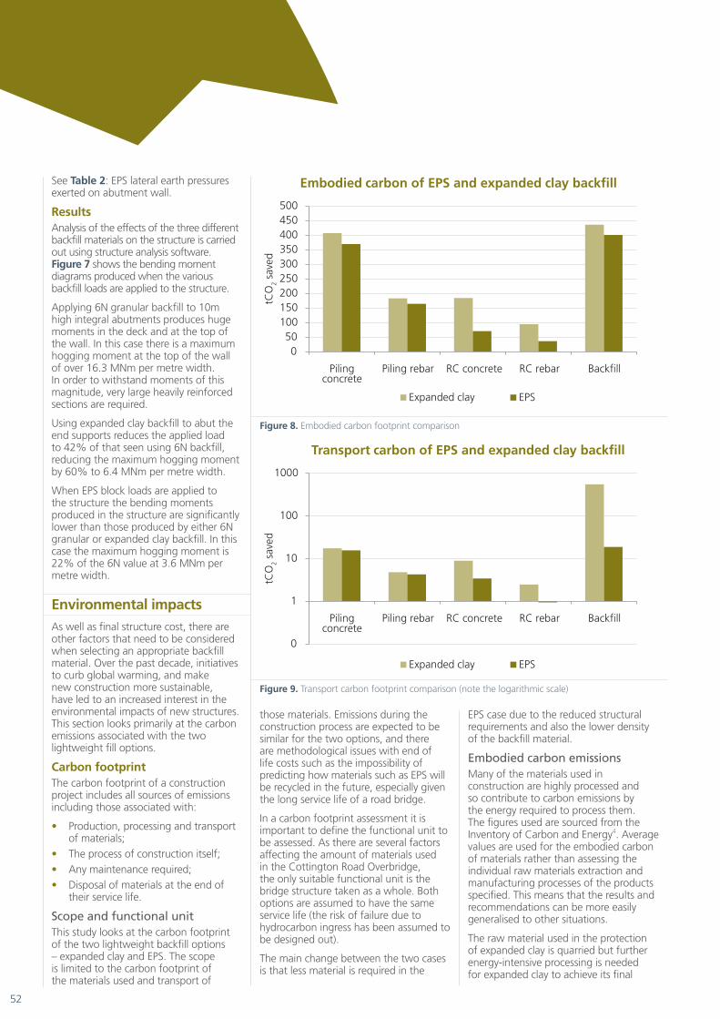
Embodied carbon emissionsMany of the materials used in construction are highly processed and so contribute to carbon emissions by the energy required to process them. The figures used are sourced from the Inventory of Carbon and Energy4. Average values are used for the embodied carbon of materials rather than assessing the individual raw materials extraction and manufacturing processes of the products specified. This means that the results and recommendations can be more easily generalised to other situations.
The raw material used in the protection of expanded clay is quarried but further energy-intensive processing is needed for expanded clay to achieve its final
Figure 8: Embodied carbon footprint comparison
Figure 9: Transport carbon footprint comparison (note the logarithmic scale)
0 50
100 150 200 250 300 350 400 450 500
Piling concrete
Piling rebar RC concrete RC rebar Backfill
tCO
2 sa
ved
Embodied carbon of EPS and expanded clay backfill
Expanded clay EPS
0
1
10
100
1000
Piling concrete
Piling rebar RC concrete RC rebar Backfill
tCO
2 sa
ved
Transport carbon of EPS and expanded clay backfill
Expanded clay EPS
Figure 10: Carbon footprint comparison
Figure 11: Breakdown of carbon footprint savings
0
200
400
600
800
1000
1200
Piling concrete
Piling rebar RC concrete RC rebar Backfill
tCO
² sav
ed
Total embodied carbon of EPS and expanded clay backfill
Expanded clay EPS
0
100
200
300
400
500
600
Piling concrete
Piling rebarRC concrete RC rebar Backfill Total
tCO
2 sa
ved
Breakdown of embodied carbon savings when specifying EPS in place of expanded clay backfill
Embodied CO2 Transport CO2
Figure 8. Embodied carbon footprint comparison
Figure 8: Embodied carbon footprint comparison
Figure 9: Transport carbon footprint comparison (note the logarithmic scale)
0 50
100 150 200 250 300 350 400 450 500
Piling concrete
Piling rebar RC concrete RC rebar Backfill
tCO
2 sa
ved
Embodied carbon of EPS and expanded clay backfill
Expanded clay EPS
0
1
10
100
1000
Piling concrete
Piling rebar RC concrete RC rebar Backfill
tCO
2 sa
ved
Transport carbon of EPS and expanded clay backfill
Expanded clay EPS
Figure 10: Carbon footprint comparison
Figure 11: Breakdown of carbon footprint savings
0
200
400
600
800
1000
1200
Piling concrete
Piling rebar RC concrete RC rebar Backfill
tCO
² sav
ed
Total embodied carbon of EPS and expanded clay backfill
Expanded clay EPS
0
100
200
300
400
500
600
Piling concrete
Piling rebarRC concrete RC rebar Backfill Total
tCO
2 sa
ved
Breakdown of embodied carbon savings when specifying EPS in place of expanded clay backfill
Embodied CO2 Transport CO2
Figure 9. Transport carbon footprint comparison (note the logarithmic scale)

53
Geotechnical
state. Due to lack of specific data, the embodied CO2 of expanded clay has been taken as that of “General simple baked clay products” at 0.22kgCO2/kg.
Conversely, the production of plastics is an energy intensive process. The embodied CO2 per kg is over 10 times that of the expanded clay at 2.5kgCO2/kg. This might be expected to make EPS blocks the least sustainable option in terms of backfill material, however it neglects the difference in weight.
As with cost the footprint should be measured per m3 which makes the two options much closer. On this metric the expanded clay gives 88kgCO2/m3 and the EPS gives 75 – 100kgCO2/m3 depending on the density of EPS specified.
See Figure 8: Embodied carbon footprint comparison.
Transport carbon emissionsConstruction materials can also be heavy which leads to a lot of transport related carbon emissions. In the case of bridge structures, the two materials which make up the majority of transport emissions are reinforced concrete and backfill as they are the major components by weight.
Unprocessed aggregates, despite their low embodied carbon per tonne, are heavy materials and so the carbon footprint of transporting them can be quite high. This also means that the total emissions are very sensitive to the distance they are transported. For the most part they are not transported far from the place they are produced.
6N granular fill is a quarried material, with a number of source locations scattered over the UK meaning that transport distances are kept to a minimum.
Of the processed materials, there are a number of concrete plants in the East Kent area and so this does not require much transport. EPS and expanded clay have to be transported greater distances to site.
See Figure 9: Transport carbon footprint comparison.
Resource useThe use of non-renewable materials has impacts beyond embodied carbon and emissions associated with transport. All materials must be disposed of at the end of their service life. None of the materials used are renewable, although they can all be re-used or recycled to some extent.
6N granular fill and expanded clay are easy to reuse or dispose of while EPS blocks are not easy to reuse, and would need to be disposed of correctly or recycled. This could include incineration with energy capture which would offset its carbon footprint to some extent.
Other environmental impactsThere are a number of other impacts which are beyond the scope of this paper. These include toxicity of materials used, emissions to air other than carbon dioxide (such as sulphur dioxide, nitrous oxides, etc). Without carrying out a more in depth life cycle analysis it is impossible to say which of the options will have the lowest impact in these other categories.
ResultsThe expanded clay option has a carbon footprint of 1,880 tonnes while the EPS option has a carbon footprint of 1,083 tonnes. Relative to the expanded clay, the EPS design saves approximately 800 tonnes of carbon dioxide emissions.
See Figure 10: Carbon footprint comparison.
The vast majority of the savings comes from avoided transport of heavy materials. In fact the savings on transportation of fill material to site has the greatest impacts on the carbon footprint of the finished structure. Fill and expanded clay are both heavy materials, relative to EPS. Embodied carbon is proportional to the weight of material used and so the embodied carbon of
Figure 8: Embodied carbon footprint comparison
Figure 9: Transport carbon footprint comparison (note the logarithmic scale)
0 50
100 150 200 250 300 350 400 450 500
Piling concrete
Piling rebar RC concrete RC rebar Backfill
tCO
2 sa
ved
Embodied carbon of EPS and expanded clay backfill
Expanded clay EPS
0
1
10
100
1000
Piling concrete
Piling rebar RC concrete RC rebar Backfill
tCO
2 sa
ved
Transport carbon of EPS and expanded clay backfill
Expanded clay EPS
Figure 10: Carbon footprint comparison
Figure 11: Breakdown of carbon footprint savings
0
200
400
600
800
1000
1200
Piling concrete
Piling rebar RC concrete RC rebar Backfill
tCO
² sav
ed
Total embodied carbon of EPS and expanded clay backfill
Expanded clay EPS
0
100
200
300
400
500
600
Piling concrete
Piling rebarRC concrete RC rebar Backfill Total
tCO
2 sa
ved
Breakdown of embodied carbon savings when specifying EPS in place of expanded clay backfill
Embodied CO2 Transport CO2
Figure 10. Carbon footprint comparison
Figure 8: Embodied carbon footprint comparison
Figure 9: Transport carbon footprint comparison (note the logarithmic scale)
0 50
100 150 200 250 300 350 400 450 500
Piling concrete
Piling rebar RC concrete RC rebar Backfill
tCO
2 sa
ved
Embodied carbon of EPS and expanded clay backfill
Expanded clay EPS
0
1
10
100
1000
Piling concrete
Piling rebar RC concrete RC rebar Backfill
tCO
2 sa
ved
Transport carbon of EPS and expanded clay backfill
Expanded clay EPS
Figure 10: Carbon footprint comparison
Figure 11: Breakdown of carbon footprint savings
0
200
400
600
800
1000
1200
Piling concrete
Piling rebar RC concrete RC rebar Backfill
tCO
² sav
ed
Total embodied carbon of EPS and expanded clay backfill
Expanded clay EPS
0
100
200
300
400
500
600
Piling concrete
Piling rebarRC concrete RC rebar Backfill Total
tCO
2 sa
ved
Breakdown of embodied carbon savings when specifying EPS in place of expanded clay backfill
Embodied CO2 Transport CO2
Figure 11. Breakdown of carbon footprint savings
104 Lightweight backfill materials in integralbridge construction

54
the EPS option is significantly lower than the expanded clay option due to its lower density.
See Figure 11: Breakdown of carbon footprint savings.
ConclusionsAlthough the results show the use of EPS blocks abutting the end supports of an integral bridge structure greatly reduces pressures exerted on the walls and design loads experienced by the bridge components as a result, it is often less economical to use this as a solution than expanded clay backfill material. Regarding the integral bridge at Cottington
Road, the EPS block and expanded clay solutions had very similar cost implications on the project; however, EPS blocks were selected because of problems experienced in controlling deflection of the independent wing walls.
EPS blocks provide a good solution to design problems such as retaining wall deflection or restraints of bearing pressure; however, in the absence of these issues the use of EPS blocks is unlikely to be financially worthwhile.
The recent increased emphasis on making structures more sustainable is likely to encourage the use of EPS blocks due to the major reduction in transport-related emissions. This may tip the balance in
favour of EPS in cases where the cost argument is marginal, or policy measures may be introduced which give the embodied and transport carbon saved a greater financial value.
Acting as a counter to this, the issues that arise with the need to protect the material from hydrocarbons and the huge effort required to rectify problems should the protection fail will make Technical Approval Authorities very reluctant to authorise this as a design solution. A robust technical solution to this problem would allow large reductions in the transport carbon footprint of backfill.
References1. Maxit. (2004). Maxit LWA – Lightweight fill for civil engineering [Brochure].2. S+B. (2010). Product Handbook – Civil Engineering [Brochure].3. Jablite. (2010). Technical Information – Civil Engineering using Fillmaster EPS [Brochure].4. Hammond, G.P. and Jones, C.I. (2008), Inventory of Carbon and Energy V1.6a [University of Bath]5. Department of Transport, Manual of Contract Documents for Highway Works, Vol 1, Specification of Highway Works,
Series 600, 2009.6. BD 37(0) Loads for Highway Bridges, Highways Agency, UK7. BD 42/96 The Design of Internal Bridges, Highways Agency, UK