lumi etc review introduction & fy08 summary
TRANSCRIPT

1
LUMI ETC ReviewIntroduction & FY08 Summary
Alex

2
Agenda
8:00 - Executive session 15ʼ08:15 Alex Ratti - Project Status (35' + 10')09:00 Howard Matis - Physics Modeling and Beam Studies (20' + 5')09:25 Break09:45 Alex Ratti - Scope to Complete (50' +10')10:45 Howard Matis - Beam Commissioning Plans (20' + 5')11:10 Alex Ratti & Sergio Zimmermann - Budget and Schedule (20' + 5')11:35 Discussion

3
Introduction
• Having to execute a project within a program, wecover two separate and nearly independent plans– Lumi Construction Project– Lumi System Commissioning with Beam
• Review the plan to complete luminosity monitorsproduction and installation
• Present plans for detector development andoperation during beam commissioning

4
Outline
• History• Status at CERN• Production and testing highlights• Path to completion (LATER TALK)
Most of my talks will cover the lumiconstruction project

5
Status of systems at CERN
Taking beam on Sep. 10 at PT5R

6
Accomplishments in FY08
• Recorded first beam on day one• Delivered four detectors to CERN• Completed (simplified) gas systems• Completed phase 1 firmware and software
programming• Systems integration underway

7
FY08 Highlights
• HV cables performance– Initial design had unexpected leaks
• Caused noise comparable to actual lumi signals– Resulted in the complete redesign of the
flange/HV cable assembly

8
FY08 Highlights (cont.)
• Recovered from HV cable leaks– Now working on integration of PA and Detector
• As we were developing a solution for HV cables, wecompleted the detectors– Two shipped and installed in LHC in Spring
• Adequate for low luminosity run in 2008• Must be retrofit to match final design
– Balance (2 more) at CERN ready for installation• New configuration completed in September

9
Cost Control Measures
• Descoping– Gas system– Online radiation damage monitoring
• Delayed– Shaper Integration– Pre-Amp Production
10
CERN’s Position
• Bravin’s memo - June 1– CERN procured and installed a PMT based
system for 2008 run– LBNL/LARP should focus on making sure
ionization chambers are ready in 2009• Devices have to be installed and commissioned by
day one of the 2009 run• CERN will monitor very closely
– Control systems support limited by beamcommissioning priority

11
Installation and Integration in LHC• After Sep.10 LHC conditions are now different
– Tunnel access now much more limited– No early beam results– Extent of the shutdown and startup not yet known
• Warmup and bakeout?– Uncertainty in LHC schedule
• Will schedule our activities accordingly
• Detector installation– Two installed systems need retrofit + two additional systems ready
to install– Will complete well in advance of 2009 startup as LHC access
permits

12
LUMI - Conceptual DesignArgon Ionization Chamber
I0τ
τ = xGAP/vD
Signal is proportional to the number of parallel gapsCapacitance add up with n. of gaps + slows down the signal
Optimized for 6 gapsMust live in a radiation environment 100 x worse thanaccelerator instruments have ever seen
!!
0
02
1)( IdttIQ " ==
V+
xGAP
NGAP=2

13
Ionization Chamber Fabrication• Electrodes and ground plane
– OFHC copper– Wire Electrical Discharge
Machining (Wire-EDM)– High precision– Ground plane center element
is e-beam welded• Sensor body
– Macor– Several fine features with high
precision– Fasteners for assembly– Over-constrained assembly
requires some craftsmanship
E-beam welding on ground plane
High aspect ratio fins on electrode
Ground plane
All body parts are Macor
1 of 4 electrodes

14
Electrical ConnectionsDust Cover
PA
LUMI (Conformal Coating)
TAN
Preamplifier Enclosure
EARTH GROUND(Tunnel)
INSTR.GROUND
Shaping Amplifier
SH
Ground Isolation
EARTH GROUND(Counting
Room)
100K
Soft Connection(Safety)
VME DAQSystem
“VME” GROUND

15
LUMI - Pulse Shaping + DAQ
• Active termination front end to properly compensate the chamber capacitance– Initial design in collaboration with Univ. di Pavia, INFN, Italy
• Pulse shaping electronics necessary to limit the noise bandwidth.
• Pulse shaping is also necessary to reduce the width of the pulse toaccommodate the 40MHz repetition rate.
• Baseline recovery (Pole-Zero cancellation)
• Shaped pulse is digitized in a mezzanine board designed for the DABIVVME64 card used as standard interface by CERN - BI
• FPGA programming by LBL, controls programming by CERN

16
Signal Processing Path
IBMS MezzanineDigitizerShaperPreamp Control and
Data Processing (STRATIX)
Memory
Slow control
VME Controller
VME/USB Bus to CERN Main DAQ
LHC Tunnel Counting Room in Service Building

17
Nomenclature
• Sensor - Copper/Macor assembly• Detector - housing, steel pressure tank• Pre-Amp Assembly• Shaper - Chassis• Detector Interface - Chassis

18
Progress Report
• Systems modeling and beam tests• Detector fabrication• Gas systems• Preamps• Readout systems• Installation

19
DAQ programming

20
DAQ Development• Adopted firmware infrastructure from AB/BI group
– Environment successfully imported at LBL
• Win/win for both groups– Much easier for CERN to import in FESA– LBL found most infrastructure work done
• Memory map defined– official interface between the LabView system from LBL and
the LHC control system
• Effort included in LAFS– Help from Elliott McCrory (FNAL at CERN for LAFS) to
integrate in the control system– AB/CO to deliver FESA class interface

21
DAQ System Layout

22
DAQ System Description and Status
• Definesparameters andfunctions
• Gas controlpanels andinterlocksalreadydeveloped– Need final
hardware fortesting

23
DAQ Phased DevelopmentFY08 - Phase I• Programming
environment– Crate operation and I/O
• Counting mode• Stacking
FY09 - Phase II• Pulse height mode• Deconvolution• Crossing angle

24
DAQ Interfaces
Top level memory organization
offset in words0x0000 - 0x003f control and status registers0x0040 - 0x0fff unused (wrapped version of first 32 words)0x1000 - 0x3fff reserved0x4000 - 0x4dec 4k averaged waveformA0x5000 - 0x5dec 4k averaged waveformB0x6000 - 0x6dec 4k counted waveformA0x7000 - 0x7dec 4k counted waveformB0x8000 - 0xffff reserved

25
DAQ Control Registers
Control and status registers0 turn counter at start of acquisition1 turns per buffer2 Thresh A3 Thresh B (in ADC unit, 0-4095, polarity in config reg)4 DEADBEEF5 06 config register7 8-15 DSP configuration for ADC A16-23 DSP configuration for ADC B
242526272829 turns lost30 current valueof turn counter31 status reg

26
DAQ Status and Config Registers
Status Register - Bit• 0 waveform buffer full• 1 error flag (data lost,
slow readout) readclear!!!!
Config Registers - Bit• 0 discriminator
polarity (0 abovethres; 1 not abovethres)
• 31-1 reserved
27
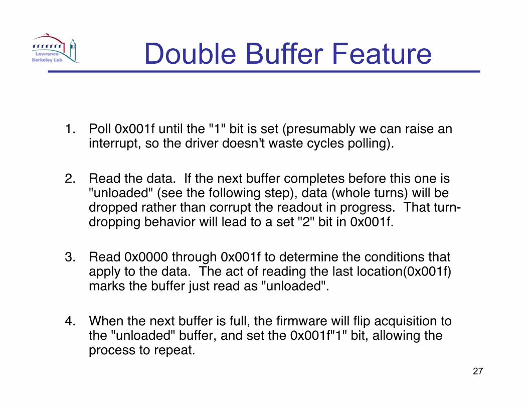
Double Buffer Feature
1. Poll 0x001f until the "1" bit is set (presumably we can raise aninterrupt, so the driver doesn't waste cycles polling).
2. Read the data. If the next buffer completes before this one is"unloaded" (see the following step), data (whole turns) will bedropped rather than corrupt the readout in progress. That turn-dropping behavior will lead to a set "2" bit in 0x001f.
3. Read 0x0000 through 0x001f to determine the conditions thatapply to the data. The act of reading the last location(0x001f)marks the buffer just read as "unloaded".
4. When the next buffer is full, the firmware will flip acquisition tothe "unloaded" buffer, and set the 0x001f"1" bit, allowing theprocess to repeat.

28
DAQ interface panel

29
Test during SPS beam test
• First test in the SPS– Good agreement
with NIM scalers– Some adjustment
required• Learned we need an
even/odd gain andoffset adjustment– IBMS boards have
two digitizers each

30
Systems Integration
Test all parts and componentsIntegration impacts signals and HV performance
31
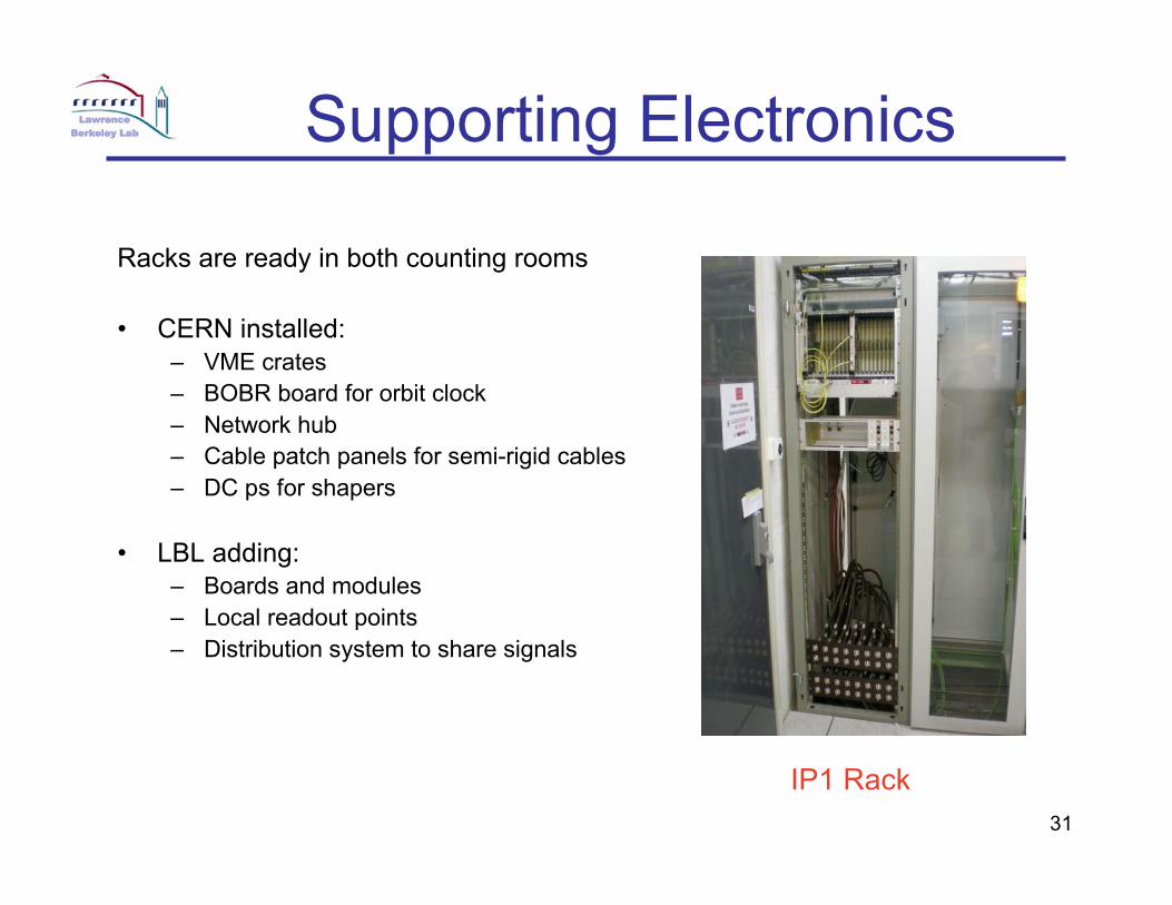
Supporting Electronics
Racks are ready in both counting rooms
• CERN installed:– VME crates– BOBR board for orbit clock– Network hub– Cable patch panels for semi-rigid cables– DC ps for shapers
• LBL adding:– Boards and modules– Local readout points– Distribution system to share signals
IP1 Rack

32
Racks Layout
• CERN provided(Yellow)
• LBL Provided (Green)• Purchases - by LBL
(Tan)

33
Gas Systems
• Designed, built, installed, tested• Software commissioning underway• Described by Howard next

34
Sensor Assembly - 1
Comb Enhancedby LBL shop

35
Sensor Assembly - 2• Mount ground block to ceramic• Connect lower quadrants
– Carefully shim to fit and align• Connect upper quadrants
– Shim as above• Close ceramic housing
– Pay attention to gas path– Make sure block mount holes are properly mounted
• Assembly takes ~ 6 - 8 hoursNote chamfer on detector edges to reduce peak
fieldsAdded after HV problems in testing

36
Sensor Assembly - 3

37
Detector Assembly
• Install glass + ceramic insulators• Install safety wire• Mount copper block
– Should be able to avoid this step in the retrofit• Mount Detector to support block• Connect quadrants• Connect RTDsTEST

38
Detector Assembly - 1
1. Install innerconductors,glass andceramicinsulators
2. Safety wiringholds ceramicstops

39
Detector Assembly - 2
3. Mount coppersupport blockto flange
Gas feedlineconnected
4. Mount sensorassembly oncoppersupport block

40
Detector Assembly - 35. Custom made
connections toeach quadrant
Adjusted for HVperformance

41
Detector Assembly - 4
Install on housingTiN seal

42
Conclusions
• Significant progress in all aspects of the project• Observed beam on day one with one detector
– Ready with a second one 5 days later• Delivered gas systems, DAQ and software
readout• All detectors at CERN
– Installation planning started• Underway with system integration• Beam test results prove detector performance