m-62-03-02 shb shc manual - process technology · pdf filem-62-03-02 shb/shc manual revision -...
TRANSCRIPT

SHB/SHC Series Inline Chemical Heater
Installation Manual Please supply your inline heater model and serial number when ordering spare parts or when requesting technical assistance.
www.processtechnology.com
7010 Lindsay Dr., Mentor, OH 44060 Phone: 440-974-1300 Fax: 440-974-9561 USA/CN: 800-621-1998
M-62-03-02 SHB/SHC Manual Revision - Date: 02 – 05/30/14
1
Table Of Contents
INTRODUCTION .................................................................................................. 2 CHEMICAL COMPATABILITY ...................................................................................................................... 4 PERFORMANCE DATA .............................................................................................................................. 5
SYSTEM SPECIFICATIONS ................................................................................ 7
MODEL NUMBER ................................................................................................ 8
FACILITY REQUIREMENTS .............................................................................. 11 SPACE-REQUIREMENTS......................................................................................................................... 11 LOCATION ............................................................................................................................................. 11 MOUNTING ............................................................................................................................................ 11 PLUMBING-REQUIREMENTS ................................................................................................................... 12 ELECTRICAL-REQUIREMENTS ................................................................................................................ 12
INSTALLATION: ................................................................................................ 13 UNCRATING AND INSPECTION ................................................................................................................ 13 COMPONENT IDENTIFICATION ................................................................................................................ 13 PROCESS-FLUID-CONNECTIONS ............................................................................................................ 14 ELECTRICAL CONNECTIONS ................................................................................................................... 14 ELEMENT-OVERTEMPERATURE-CONTROL .............................................................................................. 15 HEATER-ELEMENT-T ............................................................................................................................. 16
SAFETY FEATURES ......................................................................................... 17
OPERATION ...................................................................................................... 18 START UP ............................................................................................................................................. 18 SHUT-DOWN ......................................................................................................................................... 18 CLEANING ............................................................................................................................................. 19
MAINTENANCE ................................................................................................. 19 PREVENTIVE MAINTENANCE .................................................................................................................. 19
SERVICE ............................................................................................................ 20
WARRANTY ....................................................................................................... 21
M-62-03-02 SHB/SHC Manual Revision - Date: 02 – 05/30/14
2
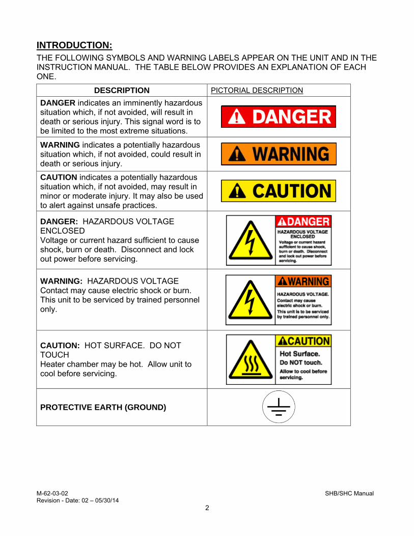
INTRODUCTION: THE FOLLOWING SYMBOLS AND WARNING LABELS APPEAR ON THE UNIT AND IN THE INSTRUCTION MANUAL. THE TABLE BELOW PROVIDES AN EXPLANATION OF EACH ONE.
DESCRIPTION PICTORIAL DESCRIPTION
DANGER indicates an imminently hazardous situation which, if not avoided, will result in death or serious injury. This signal word is to be limited to the most extreme situations.
WARNING indicates a potentially hazardous situation which, if not avoided, could result in death or serious injury.
CAUTION indicates a potentially hazardous situation which, if not avoided, may result in minor or moderate injury. It may also be used to alert against unsafe practices.
DANGER: HAZARDOUS VOLTAGE ENCLOSED Voltage or current hazard sufficient to cause shock, burn or death. Disconnect and lock out power before servicing.
WARNING: HAZARDOUS VOLTAGE Contact may cause electric shock or burn. This unit to be serviced by trained personnel only.
CAUTION: HOT SURFACE. DO NOT TOUCH Heater chamber may be hot. Allow unit to cool before servicing.
PROTECTIVE EARTH (GROUND)

M-62-03-02 SHB/SHC Manual Revision - Date: 02 – 05/30/14
3
INTRODUCTION (CONTINUED): The SHB/SHC heater by Process Technology is designed to safely heat process chemistries through indirect contact instead of direct immersion. Heating is via Process Technology’s self-limiting PTC cartridge element or through an optional resistive-style element. The wetted surfaces are constructed of either electropolished 316SS (SHB model) or high purity Fluoropolymers (SHC model) and the heater can be used in either single pass or multi-pass (recirculating) flow applications.
The SHB/SHC inline heater can withstand operation at a variety of temperature and pressure conditions. The maximum operating condition for the SHB/SHC inline heater is 180oC at 43.5 PSI.
Safe operation of this heater requires the use of over-temperature control sensors with an approved safety switching device. Operating in excess of the maximum operating temperature (180°C) can result in conditions that can cause harm to operators and equipment.
The Standard Process Technology SHB/SHC Series Heater consists of:
Fluid path of electropolished 316SS (SHB models) or FEP, PFA or PTFE (SHC models) Grounded heating element (self-limiting PTC style or resistive-style) 3 meters (10ft) Power and signal Wires (through separate conduit fittings) Heating element over-temperature sensor; 2x Thermal cut-off device (bimetallic switch), set at 260°C Polypropylene (PP) mounting brackets
The following equipment is recommended for safe operation of the SHB/SHC Inline Heater, and must be customer-supplied. Process temperature controller Liquid level sensor Proper high-voltage power fusing and electrical disconnect switch Pump motor safety interlock circuit
The Process Technology SHB/SHC heater heats process fluid to temperatures as high as 180C. However, the over-temperature protection circuit will allow the heater core to reach temperatures as high as 260C. Consult the factory BEFORE attempting to heat flammable or combustible fluids.

M-62-03-02 SHB/SHC Manual Revision - Date: 02 – 05/30/14
4
INTRODUCTION (CONTINUED): Chemical Compatibility: Consult the MSDS or chemical manufacturer to verify chemical compatibility with the SHB/SHC series heater. Wetted material consist of electropolished 316SS (SHB models) and fluoropolymer FEP, PFA and PTFE (SHC models).
Although fluoropolymer is resistant to most chemicals, there are some process chemistries with which the inline heater should not be used. These may include the following:
Chemicals that degrade or decompose when heated.
Chemicals that are flammable, explosive, or produce dangerous or irritating vapors when heated (Consult Process Technology).
Halogenated solvents which attack the fluoropolymer material.
Do not use the SHB/SHC in line heater to heat incompatible chemistries. Incompatible materials will cause corrosion/degradation of the wetted materials, which may result in a heater failure.
The Process Technology SHB/SHC heater heats process fluid to temperatures as high as 180C. However, the over-temperature protection circuit will allow the heater core to reach temperatures as high as 260C. Consult the factory BEFORE attempting to heat flammable or combustible fluids.

M-62-03-02 SHB/SHC Manual Revision - Date: 02 – 05/30/14
5
INTRODUCTION (CONTINUED):
Performance Data:
The SHB/SHC series inline heaters are designed to be used in either single pass or multi-pass (recirculating) flow applications. An application is defined as single pass when the solution will enter the heating chamber only once and must be heated to the desired temperature when it exits the heater. A multi-pass application is one in which the solution will be recirculated through the process and returned to the chamber heater, and may take several cycles through the heater to reach the desired temperature.
Single Pass Flow Application:
For single pass applications, the SHB/SHC heater is designed to provide a temperature increase at a given flow rate. Table 1 shows the maximum theoretical temperature increase (∆T) that can be achieved for continuous flow conditions. Note: values based on the specific heat/weight of water. Flow rates and inlet/outlet temperatures may result in lower values.
Flow (LPM)
Heater Power, kilowatts (kW)
Flow(GPM)
0.25 0.40 0.50 0.75 0.80 0.875 1.00 1.20 1.25 1.40 1.60 2.00
Theoretical Maximum Temperature Rise (°C)
0.1 35.7 57.1 71.4 107.1 114.2 125.0 142.8 171.4 - - - - 0.03
0.2 17.8 28.5 35.7 53.5 57.1 62.5 71.4 85.7 89.2 100.0 114.2 142.8 0.05
0.3 11.9 19.0 23.8 35.7 38.0 41.6 47.6 57.1 59.5 66.6 76.1 95.2 0.08
0.4 8.9 14.2 17.8 26.7 28.5 31.2 35.7 42.8 44.6 50.0 57.1 71.4 0.11
0.5 7.1 11.4 14.2 21.4 22.8 25.0 28.5 34.2 35.7 40.0 45.7 57.1 0.13
0.6 5.9 9.5 11.9 17.8 19.0 20.8 23.8 28.5 29.7 33.3 38.0 47.6 0.16
0.7 5.1 8.1 10.2 15.3 16.3 17.8 20.4 24.4 25.5 28.5 32.6 40.8 0.18
0.8 4.4 7.1 8.9 13.3 14.2 15.6 17.8 21.4 22.3 25.0 28.5 35.7 0.21
0.9 3.9 6.3 7.9 11.9 12.6 13.8 15.8 19.0 19.8 22.2 25.3 31.7 0.24
1.0 3.5 5.7 7.1 10.7 11.4 12.5 14.2 17.1 17.8 20.0 22.8 28.5 0.26
1.1 3.2 5.1 6.4 9.7 10.3 11.3 12.9 15.5 16.2 18.1 20.7 25.9 0.29
1.2 2.9 4.7 5.9 8.9 9.5 10.4 11.9 14.2 14.8 16.6 19.0 23.8 0.32
1.3 2.7 4.3 5.4 8.2 8.7 9.6 10.9 13.1 13.7 15.3 17.5 21.9 0.34
1.4 2.5 4.0 5.1 7.6 8.1 8.9 10.2 12.2 12.7 14.2 16.3 20.4 0.37
1.5 2.3 3.8 4.7 7.1 7.6 8.3 9.5 11.4 11.9 13.3 15.2 19.0 0.40
Table 1: Maximum Temperature Increase as a function of power vs. flow

M-62-03-02 SHB/SHC Manual Revision - Date: 02 – 05/30/14
6
INTRODUCTION (CONTINUED): Multi-Pass Flow Application:
For a multi-pass application, the SHB/SHC heater will elevate and maintain the temperature of a fixed volume of solution as it is circulated. Use the following formula to estimate the heat-up time for a volume of fluid in a multi-pass system. For estimating purposes, the specific heat and weight of water are often used. However, more accurate results will be achieved using the properties of the specific solution.
Volume X Density X Temperature rise X Specific heat
(liters(L)) (kg/L) (°C) (J/kg x °C)
Heater Power (kW) X 60,000
This formula does not take into account any heat losses to the surrounding environment. Other factors that must be considered include heat losses through plumbing and exposed process tank surfaces, and the load placed on the heater by the introduction of cold products and chemicals into process tanks.
Heat-up Time
(minutes) =

M-62-03-02 SHB/SHC Manual Revision - Date: 02 – 05/30/14
7
HEATER SPECIFICATIONS:
Product SHB/SHC Series Inline Heater
Approvals Standard - CE, UL 499, CSA C22.2 “EX” option - UL 823, Rated for Class I, Division 2 hazardous locations
Wattage 250 - 2000 watts (specified by model #)
Voltage Resistive Element PTC Element
120-600VAC, single phase, 50/60Hz (specified by model #) 120-480VAC, single phase, 50/60Hz (specified by model #)
Dimensions: Refer to heater facilities print for specific heater dimensions
Wetted surfaces: SHB models – electropolished 316SS SHC models - FEP, PFA, PTFE
Operating temperatures: Process inlet Process outlet
Up to process outlet temperature Up to 180°C (356°F), depending upon operating conditions
Ambient Air Temperature -30°C (-22°F) to 60°C (140°F)
Minimum Flow Rate 50 ml/min (0.026 gpm)
Pressure Rating at 60°C at 180°C
0.70 MPa (101.5 PSI) 0.30 MPa (43.5 PSI)
Mounting Brackets Polypropylene (standard)
Overtemperature Sensors
Refer to heater facilities print for details
Thermal Cut-Off Device bi-metallic switch, open at 260°C (500°F)
Table 2: Heater Specifications
M-62-03-02 SHB/SHC Manual Revision - Date: 02 – 05/30/14
8
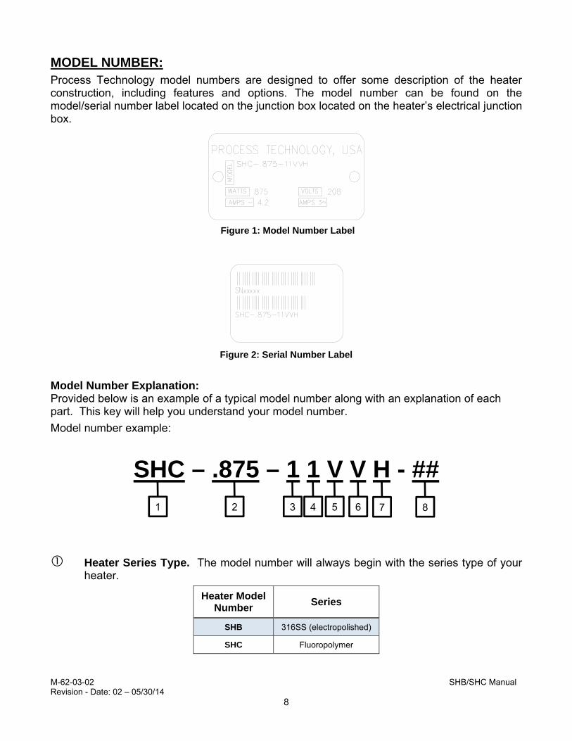
MODEL NUMBER: Process Technology model numbers are designed to offer some description of the heater construction, including features and options. The model number can be found on the model/serial number label located on the junction box located on the heater’s electrical junction box.
Model Number Explanation: Provided below is an example of a typical model number along with an explanation of each part. This key will help you understand your model number.
Model number example:
SHC – .875 – 1 1 V V H - ##
Heater Series Type. The model number will always begin with the series type of your heater.
Heater Model Number
Series
SHB 316SS (electropolished)
SHC Fluoropolymer
Figure 1: Model Number Label
Figure 2: Serial Number Label
1 2 3 4 5 6 7 8

M-62-03-02 SHB/SHC Manual Revision - Date: 02 – 05/30/14
9
Model Number Explanation (Continued):
Heater Wattage. The first number(s) in the model number will always represent the kilowattage of your heater. The table provided below identifies the standard available wattage ratings of the SHB/SHC heater.
Heater Model Number
Watts Heater Model
Number Watts
.25 250 1 1000
.4 400 1.2 1200
.5 500 1.25 1250
.75 750 1.4 1400
.8 800 1.6 1600
.875 875 2 2000
Heater Voltage. The next set of up to (2) numbers following the heater kilowattage will describe the rated voltage of the heater.
Heater Model Number
Rated Voltage (V)
Heater Model Number
Rated Voltage (V)
1 208 8 575
2 240 9 220
3 380 10 200
4 400 12 120
5 415 14 600
6 480 15 230
7 440
Voltage Supply Phase. This character indicates the phase rating of the heater.
Heater Model Number
Voltage Phase
1 Single phase

M-62-03-02 SHB/SHC Manual Revision - Date: 02 – 05/30/14
10
Model Number Explanation (Continued):
Process Inlet/Outlet Plumbing Connections. The characters used to describe the plumbing connections signify the type of connection and its size. Please refer to the table below to see the specific plumbing connections provided with the heater:
Series Heater Model
Number Description
SHB O 5/16” Tube Stub
SHC Q 1/8" Super 300 Pillar
SHC R 1/4" Super 300 Pillar
SHC T 3/8" Super 300 Pillar
SHC V 1/2" Super 300 Pillar
Element Over-temperature Sensor Type. Several element over-temperature sensor types are available for the SHB/SHC heater. Please refer to the table below for a brief listing of the available options.
Options / Non-Standard / OEM Configurations. Options and custom configurations identified using numerical and/or alphabetical characters. Examples
Heater Model Number
Description
K K-Type TC
E E-Type TC
J J-Type TC
H 100-Ohm RTD (3-wire)
R 1000-Ohm RTD (2-wire)
Heater Model Number
Description
DC Double Containment Fittings
R Resistive Style Heating Element
EX UL 823 Option

M-62-03-02 SHB/SHC Manual Revision - Date: 02 – 05/30/14
11
FACILITY REQUIREMENTS: Before installing the SHB/SHC inline heater confirm the facility requirements listed below. Space Requirements: The SHB/SHC inline heaters are designed to be installed within the tool or bench near the process tank assembly. Allow adequate space in the tool for mounting of the heater. Also provide space to make necessary power and plumbing connections to the heater.
The heater should be installed in an area free from excessive chemical or liquid exposure. The electrical junction area must not be submerged or exposed to excessive splashing or high pressure spray.
Location: The SHB/SHC inline heater is designed to be located in areas where exposure to process chemistry is likely. The heater’s external components are constructed of fluoropolymer coated materials, but is not designed to be externally submerged.
Over-pressure protection should be installed to prevent pressures in excess of the maximum pressure at a specific temperature. Reference System Specifications or the heater’s facilities print for additional information.
Mounting:
The SHB/SHC inline heater is supplied with adjustable mounting brackets. Ensure that the mounting location will adequately support the weight of the chamber, its supporting hardware and plumbing, and the fluid in the system. Heater chamber may be mounted vertically or horizontally.
Vertical
Horizontal
Figure 1: Mounting
M-62-03-02 SHB/SHC Manual Revision - Date: 02 – 05/30/14
12
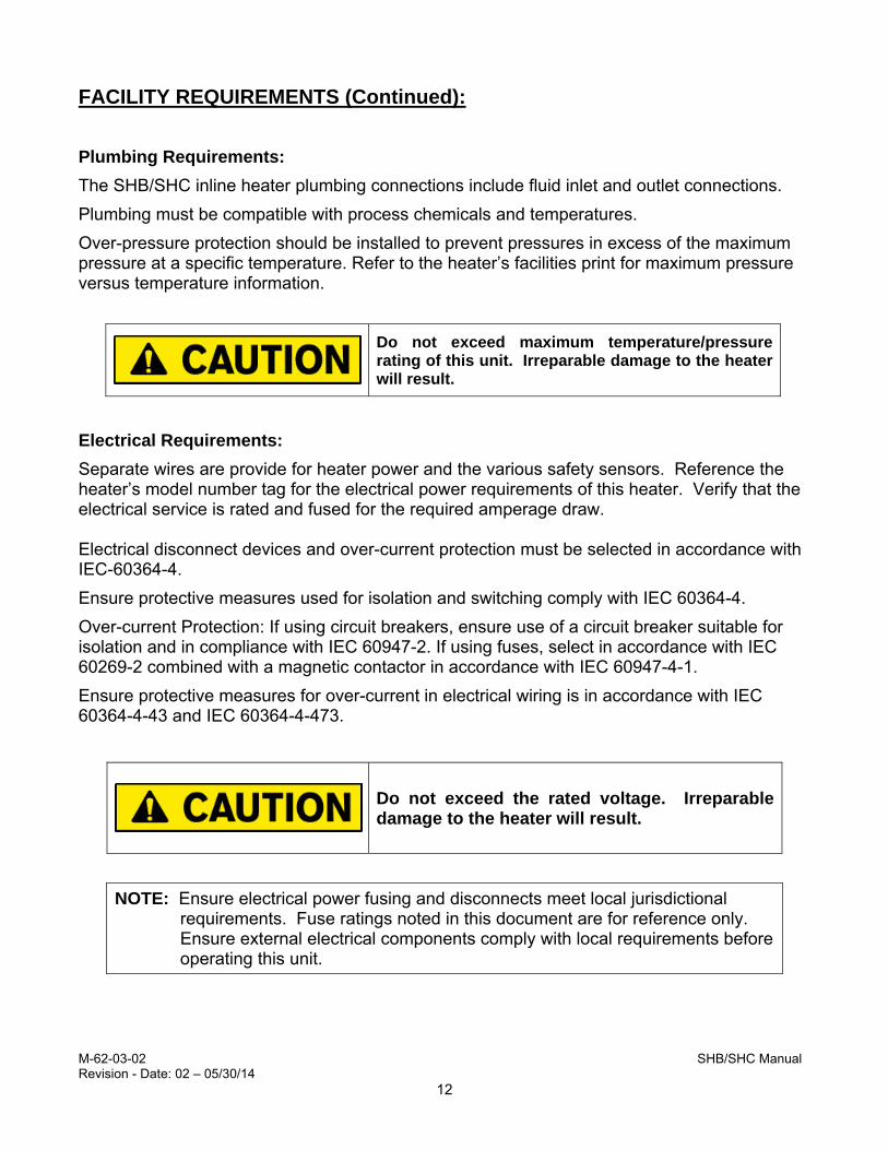
FACILITY REQUIREMENTS (Continued): Plumbing Requirements:
The SHB/SHC inline heater plumbing connections include fluid inlet and outlet connections.
Plumbing must be compatible with process chemicals and temperatures.
Over-pressure protection should be installed to prevent pressures in excess of the maximum pressure at a specific temperature. Refer to the heater’s facilities print for maximum pressure versus temperature information.
Electrical Requirements:
Separate wires are provide for heater power and the various safety sensors. Reference the heater’s model number tag for the electrical power requirements of this heater. Verify that the electrical service is rated and fused for the required amperage draw. Electrical disconnect devices and over-current protection must be selected in accordance with IEC-60364-4.
Ensure protective measures used for isolation and switching comply with IEC 60364-4.
Over-current Protection: If using circuit breakers, ensure use of a circuit breaker suitable for isolation and in compliance with IEC 60947-2. If using fuses, select in accordance with IEC 60269-2 combined with a magnetic contactor in accordance with IEC 60947-4-1.
Ensure protective measures for over-current in electrical wiring is in accordance with IEC 60364-4-43 and IEC 60364-4-473.
Do not exceed the rated voltage. Irreparable damage to the heater will result.
NOTE: Ensure electrical power fusing and disconnects meet local jurisdictional requirements. Fuse ratings noted in this document are for reference only. Ensure external electrical components comply with local requirements before operating this unit.
Do not exceed maximum temperature/pressure rating of this unit. Irreparable damage to the heater will result.
M-62-03-02 SHB/SHC Manual Revision - Date: 02 – 05/30/14
13
INSTALLATION:
Before installation, carefully read this entire section.
Uncrating and Inspection: 1) Remove the Heater assembly from its shipping container.
2) Remove box containing all support equipment.
3) Remove any protective packaging material and discard.
4) Inspect unit for any apparent physical damage.
5) Check component list for all parts.
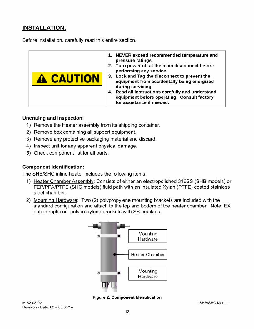
Component Identification: The SHB/SHC inline heater includes the following items:
1) Heater Chamber Assembly: Consists of either an electropolished 316SS (SHB models) or FEP/PFA/PTFE (SHC models) fluid path with an insulated Xylan (PTFE) coated stainless steel chamber.
2) Mounting Hardware: Two (2) polypropylene mounting brackets are included with the standard configuration and attach to the top and bottom of the heater chamber. Note: EX option replaces polypropylene brackets with SS brackets.
1. NEVER exceed recommended temperature and pressure ratings.
2. Turn power off at the main disconnect before performing any service.
3. Lock and Tag the disconnect to prevent the equipment from accidentally being energized during servicing.
4. Read all instructions carefully and understand equipment before operating. Consult factory for assistance if needed.
Figure 2: Component Identification
Heater Chamber
Mounting Hardware
Mounting Hardware

M-62-03-02 SHB/SHC Manual Revision - Date: 02 – 05/30/14
14
INSTALLATION (CONTINUED): Process Fluid Inlet and Outlet Connections:
1) Remove the protective plastic plugs from the inlet and outlet connections of the heater chamber assembly.
2) Connect appropriate fittings to the Inlet and Outlet of the heater chamber assembly. Refer to the fitting manufacturer’s specifications and instructions for proper installation requirements.
Electrical Connections:
The SHB/SHC inline heater has separate power and sensor wires.
Main Power:
The Power wires consist of (2) two black power leads, and (1) one green ground lead. All electrical connections and safety devices must comply with local electrical code guidelines.
1) Refer to the model number label for the power requirements for this heater.
2) Fuse the incoming power supply lines for the rated amperage using an approved electrical disconnect. The electrical disconnect must meet the following minimum requirements:
Appropriate voltage and amperage ratings for the specific heating system. Verify that all fused electrical disconnects meet jurisdictional requirements.
For safety of service and maintenance personnel, this electrical disconnect must be located within sight of the equipment.
3) Ensure that all services are off before making connections (electrical, liquids, and gas). Lockout and Tagout as appropriate. Use only approved and properly rated wire, conduit and connectors.
4) Connect heater leads to an electrical disconnect device in the customer supplied controller. This electrical disconnect must have the proper electrical rating necessary for the equipment.
5) Connect heater ground lead to proper grounding point.
Use only approved and properly rated wire, conduit and connectors.
Check all connections before applying power.

M-62-03-02 SHB/SHC Manual Revision - Date: 02 – 05/30/14
15
INSTALLATION (CONTINUED): Signal Wires:
The Signal Wires consists of the following:
Element over-temperature sensors; two each (one primary, one backup), same type.
Thermal cutoff (TCO) device
The SHB/SHC inline heater is supplied with redundant temperature monitoring capabilities to better ensure safe temperature levels. These sensors must be installed into a customer-supplied control package to protect the equipment from accidental damage and to ensure operator safety. Refer to the facilities print for the specific temperature sensors supplied with the heater.
NOTE: Failure to use the supplied over-temperature control devices for their intended purposes may void all or part of the equipment warranty. Consult factory for technical assistance.
Element Over-temperature Control Device:
The Heater Over-temperature Control Device measures the operating temperature of the heating element. This heater is supplied with two sensors for redundant element over-temperature sensing.
These sensors MUST be connected to an ELV circuit(s). These sensors MUST be connected to an approved safety switching device. Activation of the over-temperature protection should require manual reset to enable heating. These sensors are in direct physical contact with the metallic heating element sheath and consequently in contact with protective earth/ground.
M-62-03-02 SHB/SHC Manual Revision - Date: 02 – 05/30/14
16
INSTALLATION (CONTINUED): Element Over-temperature Control Device (continued):
The SHB/SHC inline heating element operates at a higher temperature than the process solution. The element over-temperature control device measures the temperature of the heating element and should interrupt the power to the heater if excessive element temperature is detected.
FOR SHB models, set the over-temperature control setting 15°C above the process temperature.
NOTE: If nuisance tripping of the over-temperature control is experienced, increase the control setting in 5°C increments until normal operation is achieved.
For SHC heaters, the element operating temperature will vary based on variables such as flow rate and inlet temperature. As such, set the element over-temperature control 5°C above the maximum normal element operating temperature, not to exceed 260°C.
Heater Element TCO (Thermal Cutoff):
The Heater Element TCO is a bimetallic switch that opens when it reaches a temperature of 260°C. This is a resettable device which must be connected to interrupt the operation of the control circuit if it is activated by an element over-temperature condition.
Do not connect the TCO in series with the heating element/main load. The TCO is designed to be wired into the heater’s safety control circuit. Protection of the circuit shall be done with a fuse, according to IEC or EN 60691 or a circuit breaker according to IEC 60947-2.

M-62-03-02 SHB/SHC Manual Revision - Date: 02 – 05/30/14
17
SAFETY FEATURES: Safety System Network:
This SHB/SHC inline heater is supplied without a Temperature Control package. Certain safety interlocks must be incorporated into the control package to prevent damage to the heater and ensure the safety of the operator. Each interlock circuit monitors a critical operating parameter of the heater. The control system is designed so that if a "fault condition" is detected by one of the sensors, the power to the heating element is disengaged. The shutdown mechanism may be momentary or latching; refer to table below.
Safety device Operation Type of Shutdown
Pump Interlock Monitors condition of pump, disrupts power to heater when pump is not in operation.
latching
Liquid Level Control
Monitors presence of adequate fluid in heater vessel, disrupts power to heater if fluid is not present in the outlet piping.
latching
Process Temperature Control Device
Monitors temperature of fluid, disrupts power to heater when temperature rises above setpoint.
momentary
Process Over-Temperature Control Device
Monitors temperature of fluid, disrupts power to heater when temperature rises above setpoint.
momentary
Heater Element Over-Temperature Control Device
Monitors temperature of heating element, disrupts power to heater when temperature rises above setpoint. (Refer to Over-temperature Control Device Settings).
latching
Heater Element TCO
Monitors temperature of heating element, disrupts power to heater when temperature rises above melt point of TCO.
latching
Table 3: Safety System Network

M-62-03-02 SHB/SHC Manual Revision - Date: 02 – 05/30/14
18
OPERATION:
During operation, the surface temperature of the heater may exceed 80°C. Avoid contact - serious personal injury may result.
Start Up Procedure:
1) Start process fluid flow. Allow solution to flow for several minutes to remove any air from the heating chamber.
2) Turn on the main power to the system.
3) Turn on the control module.
4) Verify proper reading of the process temperature.
5) Engage the control system’s safety relay, if applicable.
6) Turn on the heater.
Shut-Down Procedure:
The heater chamber may contain process solution or residue. This material should be handled with the same care and precautions as any process solution.
1) Turn off electrical power to the heater.
2) Allow heater to cool. The Inline heater may be damaged if the heater is allowed to operate in air or if residual heat is not allowed to dissipate before draining. Before the chamber is drained, the outlet temperature must be allowed to cool to within 1C of the inlet temperature. Then, wait an additional 10 minutes.
3) Turn OFF process fluid flow through the Heater.
4) Turn OFF process controller.
5) Turn OFF Main Electrical Power.
6) For extended shut down periods, drain the system.

M-62-03-02 SHB/SHC Manual Revision - Date: 02 – 05/30/14
19
OPERATION (CONTINUED): Cleaning:
This Process Technology SHB/SHC inline heater was cleaned before shipment. However, cleaning is typically required to remove any contaminants remaining after installation. The times required for cleaning of the system are dependent on DI water quality, flow rates, and installation techniques, and will vary. Additional steps may be required for some applications.
1) Operate the SHB/SHC inline heater at ambient temperature for several hours, overnight if possible, at a minimum flow rate of 2 lpm (0.5 gpm).
Small amounts of process chemistry may remain in the unit after draining. The unit should be flushed with hot water then drained several times to eliminate any residual chemistry.
Maintenance:
Preventive Maintenance of the Inline Heater Chamber:
The Process Technology SHB/SHC inline heater requires minimal preventive maintenance.
The process inlet/outlet fittings should be checked for leaks every Six Months.

M-62-03-02 SHB/SHC Manual Revision - Date: 02 – 05/30/14
20
Service: Process Technology supports its product line with a strong technical support and field service program. If your SHB/SHC heater fails to perform properly, follow the outlined steps for resolution.
1) Verify connections and program parameters.
2) Contact the Process Technology Technical Service Group. When placing this call, please have available the model number and serial number of the unit (located on the system tag), information about the application of the equipment, and information regarding the chemical constituents of the process fluid. The Service Technician will evaluate the situation and determine a course of action for troubleshooting and repair.
3) If the Technician determines that the unit should be returned to the factory for evaluation, a Returned Materials Authorization (RMA) Number will be issued. A return will not be accepted without prior authorization.
To protect the safety of Process Technology’s workers and any others that may come in contact with the SHB/SHC in the course of transport, evaluation, and repair, Process Technology requires that these practices be followed in returning the equipment to the factory:
1) Rinse the equipment until it is free of any chemical residuals. This is required for safe transport and handling of the equipment.
2) Wrap the unit in plastic and secure. Make sure that it does not leak. (Process Technology is not responsible for damage caused by leakage during shipping.)
3) Carefully package the unit for shipment.
4) Indicate the type of chemical that was in use at the time of failure. Include this information on the packing slip or place the information on the outside of the box. Process Technology will not risk exposure of its personnel to unknown chemicals. A return will not be evaluated until chemical information is received.
NOTE: Because of the configuration of the heating coils within the unit, it is possible that process fluid residues may remain even after thorough rinsing. Chemical information must be included even when a unit is believed to be clean so that Process Technology may protect its workers from exposure to these residues.
5) Clearly mark the outside of the box with the RMA number.
6) Ship the component prepaid to Process Technology.
On receipt of a returned unit, Process Technology will follow these steps:
1) The equipment will be carefully unpacked, inspected and cleaned, and an evaluation will be done.
2) A Process Technology technician will contact you with information regarding the scope of work to be performed, the cost, and the amount of time needed.
3) After a purchase order and authorization to perform the repair are received, the repairs will be completed and the unit returned.

M-62-03-02 SHB/SHC Manual Revision - Date: 02 – 05/30/14
21
WARRANTY: All PROCESS TECHNOLOGY equipment, heaters and controls have been carefully inspected before shipping and are warranted to be free from defects in workmanship and materials for a period of one year from date of purchase on a pro-rated basis. At its option, PROCESS TECHNOLOGY will repair or replace any defects that are exhibited under proper and normal use. PROCESS TECHNOLOGY disclaims any responsibility for misuse, misapplication, negligence or improper installation of equipment, tempering or other operating conditions that are beyond its control (such as excessively high or low purge gas supply pressure). PROCESS TECHNOLOGY makes no warranty or representation regarding the fitness for use or the application of its products by the customer.
All products and components not manufactured by PROCESS TECHNOLOGY will carry the original manufacturer's warranty, copies of which are available upon request. PROCESS TECHNOLOGY makes no warranty or representation, expressed or implied, with respect to the products not manufactured by PROCESS TECHNOLOGY.
Products must be installed and maintained in accordance with PROCESS TECHNOLOGY instructions.
PROCESS TECHNOLOGY is not liable for labor costs incurred in removal, reinstallation, or unauthorized repair of the product or for damage of any type including incidental or consequential damage.
PROCESS TECHNOLOGY neither assumes nor authorizes any representative of PROCESS TECHNOLOGY or any other person to assume for it any other liabilities in connection with the sale of the products. This warranty may not be verbally changed or modified by any representative of PROCESS TECHNOLOGY.
Shipping Damages: Claims against freight carriers for damage in transit must be filed by the customer at the time of delivery or as soon as possible.
Returns: No product shall be returned to PROCESS TECHNOLOGY without first obtaining a return material authorization (RMA) number from a PROCESS TECHNOLOGY representative. All returns must be freight prepaid. Freight collect or shipments without authorization will be refused.
Information: PROCESS TECHNOLOGY will endeavor to furnish such advice as it may be able to supply with reference to the use by buyer of any material purchased, but PROCESS TECHNOLOGY makes no guarantees and assumes no obligation or liability for advice given verbally or in print or the results obtained. Buyer assumes all risk and liability that may result from the use of any material, whether used by itself or in combination with other products. No suggestion for product use shall be construed as a recommendation for its use in infringement on any existing patent.
Conflict Between Documents: Acceptance of this offer is expressly conditioned upon agreement to all terms and conditions contained herein. In the event of a conflict between the terms and conditions of purchaser's purchase order, and PROCESS TECHNOLOGY‘s terms and conditions, proposal or offer, the latter shall govern.