m. sc. final report (md. nazmul haque, roll-1295)
TRANSCRIPT

A REVIEW ON THE TREATMENT TECHNOLOGIES OF INDUSTRIAL
WASTEWATER
A Project Report Submitted to the Department of Environmental Sciences,
Jahangirnagar University, in Partial Fulfillment of the Requirements for the Degree
of MASTER OF SCIENCE (M.Sc.) IN ENVIRONMENTAL SCIENCE
Course No. Env.530
SUBMITTED BY
Exam. Roll: Env. 060518
Reg. No: 17756
Session: 2005-2006
Department of Environmental Sciences
Jahangirnagar University
Savar, Dhaka-1342
September, 2008

i
DEDICATED
TO
MY BELOVED
PARENTS

ii
ABSTRACT
Different types of technologies used for the treatment of industrial wastewater were
summarized in this review paper and the removal efficiency of the technologies were
reviewed by collecting data from the treatment technologies used for the removal of
particular parameters. It was found that, internal circulation (IC) anaerobic reactor &
sequencing batch reactor (SBR) are efficient techniques for BOD5 removal, sequencing
batch reactor (SBR) is efficient technique for COD removal, predenitrification system is
efficient technique for TOC removal, circulating bioreactor is efficient technique for total
nitrogen (TN) removal and internal circulation (IC) anaerobic reactor & sequencing batch
reactor (SBR) are efficient techniques for ammonia nitrogen (NH3-N) removal, various
yeast species and sequencing batch reactor (SBR) are efficient techniques for
phosphorus removal. A large amount of untreated industrial wastewater is released into
surrounding areas of the industries daily in Bangladesh. So, these technologies can be
used for the treatment of industrial wastewater in Bangladesh to control industrial
pollution.

iii
List of Acronyms and Abbreviations
BOD Biochemical Oxygen Demand
COD Chemical Oxygen Demand
TOC Total Organic Carbon
TN Total Nitrogen
TP Total Phosphorus
PAH Polycyclic Aromatic Hydrocarbons
SS Suspended Solids
VOCs Volatile Organic Compounds
DO Dissolved Oxygen
DoE Department of Environment
EPA Environmental Protection Agency
AEPA Australian Environmental Protection Authority

iv
CONTENTS
Dedication ………………………………………………………………………………………………………. i
Abstract ………………………………………………………………………………………………………….. ii
List of Acronyms and Abbreviations ……………………………………………………………….. iii
Contents …………………………………………………………………………………………………………. iv-x
List of Tables …………………………………………………………………………………………………… viii
List of Figures …………………………………………………………………………………………………. ix-x
CHAPTER ONE: INTRODUCTION
01-25
1.1 General …………………………………………………………………………………….. 01
1.2 Wastewater…………………………………………………………………………….... 02
1.3 Composition of Wastewater …………………………………………………….. 02
1.4 Types of wastewater………………………………………………………………….. 03
1.5 Industrial wastewater ……………………………………………………………….. 04
1.6 Sources of industrial wastewater ……………………………………………… 05
1.6.1 Agricultural waste …………………………………………………………………….. 05
1.6.2 Iron and steel industry ………………………………………………………………. 08
1.6.3 Mines and quarries …………………………………………………………………… 08
1.6.4 Food industry ……………………………………………………………………………. 09
1.6.5 Complex organic chemicals industry …………………………………………. 10
1.6.6 Nuclear industry ……………………………………………………………………….. 10
1.7 Nature and Characteristics of industrial wastewater ………………… 10
1.7.1 Physical Characteristics …………………………………………………………….. 11
1.7.2 Chemical Characteristics …………………………………………………………… 13
1.7.3 Biological Characteristics …………………………………………………………… 17

v
1.8 Wastewater treatment ……………………………………………………………… 18
1.9 Industrial wastewater treatment ………………………………………………. 19
1.10 History of wastewater treatment ……………………………………………… 19
1.11 Necessity of wastewater treatment ………………………………………….. 20
1.12 Impacts of wastewater ……………………………………………………………… 21
1.12.1 Impacts of wastewater on human health …………………………………. 21
1.12.2 Effects of phosphorus on fish and other forms of aquatic life …… 22
1.12.3 Toxicity of heavy metals on microorganisms …………………………….. 22
1.13 Industrial scenario of Bangladesh ……………………………………………… 23
1.14 Objectives …………………………………………………………………………………. 25
CHAPTER TWO: MATERIALS AND METHODS
26-70
2.1 Wastewater Treatment Technologies ……………………………………….. 26
2.2 Wastewater Treatment Methods ……………………………………………… 26
2.2.1 Physical unit operations ……………………………………………………………. 27
2.2.1.1 Screening ………………………………………………………………………………….. 27
2.2.1.2 Comminution ……………………………………………………………………………. 29
2.2.1.3 Flow equalization ……………………………………………………………………… 29
2.2.1.4 Sedimentation ………………………………………………………………………….. 30
2.2.1.5 Flotation …………………………………………………………………………………… 32
2.2.1.6 Granular medium filtration ……………………………………………………….. 34
2.2.2 Chemical unit processes ……………………………………………………………. 34
2.2.2.1 Chemical precipitation ……………………………………………………………… 34
2.2.2.2 Adsorption with activated carbon …………………………………………….. 36
2.2.2.3 Disinfection ………………………………………………………………………………. 37

vi
2.2.2.4 Dechlorination ………………………………………………………………………….. 39
2.2.2.5 Other chemical applications ……………………………………………………… 39
2.2.3 Biological unit processes …………………………………………………………… 40
2.2.3.1 Activated-sludge process ………………………………………………………….. 41
2.2.3.2 Aerated lagoons ………………………………………………………………………… 43
2.2.3.3 Trickling filters ………………………………………………………………………….. 46
2.2.3.4 Rotating biological contactors …………………………………………………… 50
2.2.3.5 Stabilization ponds ……………………………………………………………………. 52
2.2.3.6 Completely mixed anaerobic digestion ……………………………………… 54
2.2.3.7 Biological nutrient removal ………………………………………………………. 56
2.2.3.7.1 Nitrification-denitrification ……………………………………………………….. 56
2.2.3.7.2 Phosphorus removal …………………………………………………………………. 57
2.3 Application of Treatment Methods …………………………………………… 58
2.3.1 Preliminary treatment ………………………………………………………………. 58
2.3.2 Primary treatment ……………………………………………………………………. 59
2.3.3 Secondary treatment ………………………………………………………………… 59
2.3.4 Tertiary/advanced wastewater treatment ………………………………… 59
2.4 Natural Treatment Systems ………………………………………………………. 60
2.4.1 Land treatment …………………………………………………………………………. 60
2.4.1.1 Slow rate …………………………………………………………………………………… 61
2.4.1.2 Rapid infiltration ……………………………………………………………………….. 62
2.4.1.3 Overland flow …………………………………………………………………………… 62
2.4.2 Constructed wetlands ……………………………………………………………….. 63
2.4.2.1 Free water surface systems ………………………………………………………. 63
2.4.2.2 Subsurface flow systems …………………………………………………………… 64

vii
2.4.3 Floating aquatic plants ……………………………………………………………… 64
2.5 Recent techniques ……………………………………………………………………. 65
2.5.1 Sequencing batch reactor …………………………………………………………. 65
2.5.2 Membrane Bioreactors (MBR) …………………………………………………. 66
2.5.3 Upward-flow Anaerobic Sludge Bed (UASB) ……………………………… 68
2.5.4 Expanded Granular Sludge Bed (EGSB) ……………………………………… 69
2.5.5 Reversing Anaerobic Upflow System (RAUS) ……………………………. 70
CHAPTER THREE: RESULTS AND DISCUSSIONS
71-83
3 Removal of Individual parameters …………….………………………………. 71
3.1 BOD5 removal ……………………………………………………..……………………. 71
3.2 COD removal ……………………………………………………………………..……… 73
3.3 Total Organic Carbon (TOC) removal ………………………………………… 77
3.4 Nitrogen (N) removal ………………………………………………………………… 78
3.5 Phosphorus (P) removal ……………………………………………………………. 80
3.6 Selenium (Se) removal ……………………………………………………………… 82
3.7 Lead (Pb) removal …………………………………………………………………….. 82
3.8 Manganese (Mn) removal …………………………………………………………. 82
3.9 Suspended Solid (SS) removal …………………………………………………… 82
3.10 Odor removal ……………………………………………………………………………. 83
3.11 Color removal …………………………………………………………………………… 83
CHAPTER FOUR: CONCLUSION
84-88
CHAPTER FIIVE: REFERENCES
89-97

viii
LIST OF TABLES
Table No. Table Names Page No.
Table 1.1 Typical pollutant concentrations in a variety of industrial
wastewaters ………………………………………………………………………..
03
Table 1.2 Types of wastewater …………………………………………………………… 04
Table 1.3 Typical range of BOD and SS load for industrial wastewater… 11
Table 2.1 Screen types ……………………………………………………………………….. 28
Table 2.2 Basic flow equalization processes ……………………………………….. 30
Table 2.3 Flotation methods ………………………………………………………………. 33
Table 2.4 Removal efficiency of plain sedimentation vs. chemical
precipitation ………………………………………………………………………..
35
Table 2.5 Characteristics of common disinfecting agents 38
Table 2.6 Other chemical applications in wastewater treatment and
disposal ……………………………………………………………………………….
40
Table 2.7 Advantages and disadvantages of activated-sludge process... 43
Table 2.8 Advantages and disadvantages of trickling filter …………………. 50
Table 2.9 Advantages and disadvantages of rotating biological
contactor (RBC) ……………………………………………………………………
52
Table 2.10 Types and applications of stabilization ponds ……………………… 53
Table 2.11 Advantages and disadvantages of stabilization ponds ………… 54
Table 2.12 Mechanisms of wastewater constituent removal by SR
systems ……………………………………………………………………………….
61
Table 3.1 Removal efficiency of BOD5 ………………………………………………… 71
Table 3.2 Removal efficiency of COD …………………………………………………. 73
Table 3.3 Removal efficiency of nitrogen ……………………………………………. 78
Table 3.4 Removal efficiency of phosphorus ………………………………………. 80
ix
LIST OF FIGURES
Figure
No.
Figure Names Page
No.
Fig. 1.1 Sources of wastewater …………………………………………………………………… 05
Fig. 1.2 Wastewater discharging from dying industries ………………………………. 23
Fig. 2.1 Settling basin with horizontal flow ……………………….………………………… 32
Fig. 2.2 Typical flotation unit ………………………………………………………………………. 33
Fig. 2.3 A once-through chemical treatment system …………………………………… 36
Fig. 2.4 A typical granular activated carbon contactor ………………………………… 37
Fig. 2.5 Diagram of a simple activated sludge system ……………………….………… 41
Fig. 2.6 Typical flow diagram for an activated-sludge process ………….…………. 42
Fig. 2.7 Typical flow diagram for aerated lagoons …………….………………………… 44
Fig. 2.8 A Typical Surface-Aerated Basing …………………………………………………… 44
Fig. 2.9 Diagram of aerobic (top) and facultative (bottom) aerated lagoons… 45
Fig. 2.10 A typical complete trickling filter system ………………………………………… 48
Fig. 2.11 Cutaway view of a trickling filter …………………………………………………….. 49
Fig. 2.12 Typical flow diagram for trickling filters …………………………………………. 50
Fig. 2.13 RBC system configuration ………………………………………………………………. 51
Fig. 2.14 Schematic diagram of a typical rotating biological contactor (RBC)…. 51
Fig. 2.15 Typical flow diagram for RBC units …………………………………………………. 52
Fig. 2.16 Typical flow diagram for stabilization ponds …………………………………… 53
Fig. 2.17 Diagram of an anaerobic digestion process ……………………………………. 55
Fig. 2.18 Biological phosphorus removal systems …………………………………………. 58
Fig. 2.19 Various treatment levels in a wastewater treatment plant flow
diagram ………………………………………………………………………………………….
60
Fig. 2.20 Rapid infiltration treatment system ……………………………………………….. 63
Fig. 2.21 Free water surface system ……………………………………………………………… 63
Fig. 2.22 Subsurface flow system ………………………………………………………………….. 64
Fig. 2.23 Floating aquatic plants system ……………………………………………………….. 64
Fig. 2.24 Typical schematic for membrane bioreactor system ………………………. 67

x
Fig. 2.25 The upward-flow anaerobic sludge bed (UASB) reactor concept ……. 69
Fig. 2.26 The expanded granular sludge bed (EGSB) reactor concept ……………. 70
Fig. 2.27 The RAUS System ……………………………………………………………………………. 70
Fig. 4.1 BOD5 removal efficiencies of various techniques ….………………………… 84
Fig. 4.2 COD removal efficiencies of various techniques …………….………………. 85
Fig. 4.3 TOC removal efficiencies of various techniques ……………………………… 85
Fig. 4.4.1 Total nitrogen (TN) removal efficiencies of various techniques ………. 86
Fig. 4.4.2 Ammonia nitrogen (NH3-N) removal efficiencies of various
techniques ……………………………………………………………….……………………..
86
Fig. 4.5 Phosphorus removal efficiencies of various techniques ….……………… 87
Fig. 4.6 Removal efficiencies of various techniques used for the removal of
selenium (Se), lead (Pb) and manganese (Mn) ………………………………..
87
Fig. 4.7 Removal efficiencies of various techniques used for the removal of
suspended solid (SS), odor and color ………………………………………………
88

CHAPTER ONE
INTRODUCTION

1
1.1 General
Water has been and will continue to be a major factor for the survival of humans
and human activities that needs certain concern and protection. Because of the limited
resources of fresh water, careful use and frequent reuse after appropriate treatment are
requirements for sustainable development and a healthy life.
Many industries use large volumes of water in their manufacturing operations. Industrial
waste water treatment systems treat wastewater from an industrial or manufacturing
process such as a cooling tower, food or animal processing plant or any type of
manufacturing process that generates wastewater.
As industrial development in the world, mostly in newly industrialized countries grew
significantly, amounts of industrial wastewater have been drastically increasing each
year. The amounts of heavy metals and synthesized organic compounds generated by
industrial activities have increased and some 10,000 new organic compounds are added
each year. Nevertheless, these compounds are complex, difficult and costly to treat by
conventional wastewater treatment processes. For example, wastes from manufacturing
plants contribute to pollution generation and environmental degradation e.g. textile,
semiconductor, palm oil mill and rubber processing plants (Sairan and Ujang, 2004).
Much of the water used by homes, industries, and businesses must be treated before it
is released back to the environment. Nature has an amazing ability to cope with small
amounts of water wastes and pollution, but it would be overwhelmed if we didn't treat
the billions of gallons of wastewater and sewage produced every day before releasing it
back to the environment. Treatment plants reduce pollutants in wastewater to a level
nature can handle. Wastewater is used water. It includes substances such as human
waste, food scraps, oils, soaps and chemicals. Pollution of water by industrial effluents of
process industries is a serious problem in most countries. The major aim of wastewater
treatment is to remove as much of the suspended solids as possible before the
remaining water, called effluent, is discharged back to the environment.

2
Increasing urban populations and production growth boost volumes of wastewater.
In large parts of the world, substantial amounts of the discharges of domestic sewage
and industrial effluents are still untreated. And in urban areas with sewage treatment
plants, treatment capacities are often far exceeded by the rapid pace of urban growth
and development.
1.2 Wastewater
Wastewater is any water that has been adversely affected in quality by anthropogenic
influence. It comprises liquid waste discharged by domestic residences, commercial
properties, industry, and/or agriculture and can encompass a wide range of potential
contaminants and concentrations. In the most common usage, it refers to the municipal
wastewater that contains a broad spectrum of contaminants resulting from the mixing
of wastewaters from different sources.
1.3 Composition of Wastewater
The composition of wastewater varies widely. This is a partial list of what it may contain:
• Water ( > 95%) which is often added during flushing to carry the waste down a
drain
• Pathogens such as bacteria, viruses, prions and parasitic worms.
• Non-pathogenic bacteria (> 100,000 / ml for sewage)
• Organic particles such as faeces, hairs, food, vomit, paper fibers, plant material,
humus, etc.
• Soluble organic material such as urea, fruit sugars, soluble proteins, drugs,
pharmaceuticals, etc.
• Inorganic particles such as sand, grit, metal particles, ceramics, etc.
• Soluble inorganic material such as ammonia, road-salt, sea-salt, cyanide,
hydrogen sulphide, thiocyanates, thiosulphates, etc.
• Animals such as protozoa, insects, arthropods, small fish, etc.
• Macro-solids such as sanitary towels, nappies/ diapers, condoms, needles,
children's toys, dead pets, body parts, etc.
• Gases such as hydrogen sulphide, carbon dioxide, methane, etc.

3
• Emulsions such as paints, adhesives, mayonnaise, hair colorants, emulsified oils,
etc.
• Toxins such as pesticides, poisons, herbicides, etc.
Industrial wastewater quality varies among industries. Table 1.1 summarizes the typical
wastewater composition from various industrial sources.
Table 1.1: Typical pollutant concentrations in a variety of industrial wastewaters
Pollutant Units Pulp and
Paper
Petroleum
Refinery
Paint
Production
Textile
Mills
Starch
Production
BOD5 mg/L 100–500 10–800 – 75–6,300 1,500–8,000
COD mg/L 600–1,000 50–600 19,000 220–31,300 1,500–10,000
TSS mg/L 500–1,200 10-300 – 25–24,500 100–600
VSS mg/L 100–250 16,000 100–400 –
TDS mg/L – 1,500–3,000 – 500–3,000 –
NH4+ mg/L – 0.05–300 – – 10–100
TN mg/L – 90 10–30 150–600
TP mg/L – 1–10 25 – –
pH 6–8 8.5–9.5 6.9 6–12 3.5–8
Sulfates/
sulfides
mg/L – Nondetect–
400
TOC mg/L – 10–500
Oil and
Grease
mg/L – 10–700
Phenols mg/L – 0.5–100
(Adapted from a table in Kadlec and Knight, 1996)
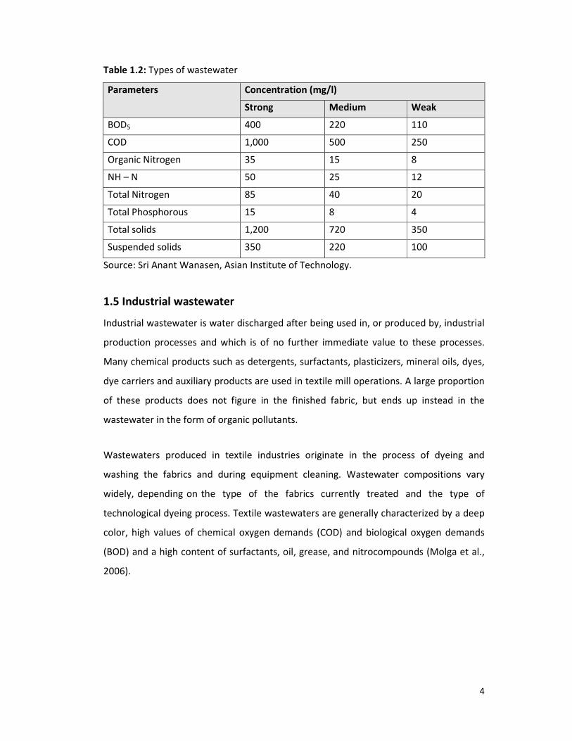
1.4 Types of wastewater
The strength of wastewater depends mainly on the degree of water dilution.
Wastewater can therefore be categorized as strong, medium and weak. Strong
wastewater has a higher BOD level than medium wastewater and so on.
4
Table 1.2: Types of wastewater
Parameters Concentration (mg/l)
Strong Medium Weak
BOD5 400 220 110
COD 1,000 500 250
Organic Nitrogen 35 15 8
NH – N 50 25 12
Total Nitrogen 85 40 20
Total Phosphorous 15 8 4
Total solids 1,200 720 350
Suspended solids 350 220 100
Source: Sri Anant Wanasen, Asian Institute of Technology.
1.5 Industrial wastewater
Industrial wastewater is water discharged after being used in, or produced by, industrial
production processes and which is of no further immediate value to these processes.
Many chemical products such as detergents, surfactants, plasticizers, mineral oils, dyes,
dye carriers and auxiliary products are used in textile mill operations. A large proportion
of these products does not figure in the finished fabric, but ends up instead in the
wastewater in the form of organic pollutants.
Wastewaters produced in textile industries originate in the process of dyeing and
washing the fabrics and during equipment cleaning. Wastewater compositions vary
widely, depending on the type of the fabrics currently treated and the type of
technological dyeing process. Textile wastewaters are generally characterized by a deep
color, high values of chemical oxygen demands (COD) and biological oxygen demands
(BOD) and a high content of surfactants, oil, grease, and nitrocompounds (Molga et al.,
2006).

5
1.6 Sources of industrial wastewater
The sources of industrial wastewater are given below. Figure 1.1 shows the Sources of
wastewater.
Figure 1.1: Sources of wastewater (Metcalf and Eddy, 2003).
1.6.1 Agricultural waste
Agricultural wastewater treatment relates to the treatment of wastewaters produced in
the course of agricultural activities. As agriculture is a highly intensified industry in many
parts of the world, the range of wastewaters requiring treatment can encompass at least
the following:
� Animals wastes - both liquid and solid

6
� Silage liquor
� Pesticide run off and surpluses
� Milking parlor wastes including milk
� Slaughtering waste
� Vegetable washing water
� Fire water
a) Animal wastes
The constituents of animal wastewater typically contain
� Strong organic content—much stronger than human sewage
� High solids concentration
� High nitrate and phosphorus content
� Antibiotics
� Synthetic hormones
� Often high concentrations of parasites and their eggs
� Spore of cryptosporidium - a bacterium resistant to drinking water treatment
processes
� Spore of Giardia
� Human pathogenic bacteria such as Brucella and Salmonella
Animal wastes from cattle can be as produced as solid or semisolid manure or as liquid
slurry. The production of slurry is especially common in housed dairy cattle.
b) Piggery waste
Piggery waste is comparable to other animal wastes except that many piggery wastes
contain elevated levels of copper that can be toxic in the natural environment. Ascarid
worms and their eggs are also common and can infect humans if wastewater treatment
is ineffective.
c) Silage liquor
Fresh or wilted grass or other green crops can be made into the semi fermented product
called silage which can be stored and used as winter forage for cattle and sheep. The

7
production of silage often involves the use of an acid conditioner such as sulfuric acid or
formic acid. The process of silage making frequently produces a yellow-brown strongly
smelling liquid which is very rich in simple sugars, alcohol, short-chain organic acids and
silage conditioner. This liquor is one of the most polluting organic substances known.
The volume of silage liquor produced is generally in proportion to the moisture content
of the ensiled material.
d) Pesticide runoff and surpluses
Inappropriate use of pesticides so that pesticide-containing wastewaters enter the
environment can give rise to severe and long-lasting ecological damage. This is
particularly true for insecticides used in sheep dips because of the volumes of pesticide-
containing wastewater requiring disposal and because of the persistent and damaging
nature of the pesticides.
e) Milking parlor wastes including milk
Although milk has a deserved reputation as an important and valuable food product, its
presence in wastewaters is highly polluting because of its organic strength, which can
lead to very rapid de-oxygenation of receiving waters. Milking parlor wastes also contain
large volumes of wash-down water, some animal waste together with cleaning and
disinfection chemicals.
f) Slaughtering waste
Wastewater from slaughtering activities is similar to milking parlor waste although
considerably stronger in its organic composition and therefore potentially much more
polluting.
g) Vegetable washing water
Washing of vegetables produces large volumes of water contaminated by soil and
vegetable pieces. Low levels of pesticides used to treat the vegetables may also be
present together with moderate levels of disinfectants such as chlorine.

8
h) Fire water
Although few farms plan for fires, fires are nevertheless more common on farms than on
many other industrial premises. Stores of pesticides, herbicides, fuel oil for farm
machinery and fertilizers can all help promote fire and can all be present in
environmentally lethal quantities in wastewater from firefighting at farms.
1.6.2 Iron and steel industry
The production of iron from its ores involves powerful reduction reactions in blast
furnaces. Cooling waters are inevitably contaminated with products especially ammonia
and cyanide. Production of coke from coal in coking plants also requires water cooling
and the use of water in by-products separation. Contamination of waste streams
includes gasification products such as benzene, naphthalene, anthracene, cyanide,
ammonia, phenols , cresols together with a range of more complex organic compounds
known collectively as polycyclic aromatic hydrocarbons (PAH).
The conversion of iron or steel into sheet, wire or rods requires hot and cold mechanical
transformation stages frequently employing water as a lubricant and coolant.
Contaminants include hydraulic oils, tallow and particulate solids. Final treatment of iron
and steel products before onward sale into manufacturing includes pickling in strong
mineral acid to remove rust and prepare the surface for tin or chromium plating or for
other surface treatments such as galvanization or painting. The two acids commonly
used are hydrochloric acid and sulfuric acid. Wastewaters include acidic rinse waters
together with waste acid. Although many plants operate acid recovery plants,
(particularly those using Hydrochloric acid), where the mineral acid is boiled away from
the iron salts, there remains a large volume of highly acid ferrous sulfate or ferrous
chloride to be disposed of. Many steel industry wastewaters are contaminated by
hydraulic oil also known as soluble oil.
1.6.3 Mines and quarries
The principal waste-waters associated with mines and quarries are slurries of rock
particles in water. These arise from rainfall washing exposed surfaces and haul roads
and also from rock washing and grading processes. Volumes of water can be very high,

9
especially rainfall related arisings on large sites. Some specialist separation operations
such as coal washing to separate coal from native rock using density gradients can
produce wastewater contaminated by fine particulate hematite and surfactants. Oils and
hydraulic oils are also common contaminants. Wastewater from metal mines and ore
recovery plants are inevitably contaminated by the minerals present in the native rock
formations. Following crushing and extraction of the desirable materials, undesirable
materials may become contaminated in the wastewater. For metal mines, this can
include unwanted metals such as zinc and other materials such as arsenic. Extraction of
high value metals such as gold and silver may generate slimes containing very fine
particles in where physical removal of contaminants becomes particularly difficult.
1.6.4 Food industry
Wastewater generated from agricultural and food operations have distinctive
characteristics that set it apart from common municipal wastewater managed by public
or private wastewater treatment plants throughout the world: it is biodegradable and
nontoxic, but that has high concentrations of biochemical oxygen demand (BOD) and
suspended solids (SS). The constituents of food and agriculture wastewater are often
complex to predict due to the differences in BOD and pH in effluents from vegetable,
fruit, and meat products and due to the seasonal nature of food processing and post
harvesting.
Processing of food from raw materials requires large volumes of high grade water.
Vegetable washing generates waters with high loads of particulate matter and some
dissolved organics. It may also contain surfactants.
Animal slaughter and processing produces very strong organic waste from body fluids,
such as blood, and gut contents. This wastewater is frequently contaminated by
significant levels of antibiotics and growth hormones from the animals and by a variety
of pesticides used to control external parasites. Insecticide residues in fleeces are a
particular problem in treating waters generated in wool processing.

10
Processing food for sale produces wastes generated from cooking which are often rich in
plant organic material and may also contain salt, flavorings, coloring material and acids
or alkali. Very significant quantities of oil or fats may also be present.
1.6.5 Complex organic chemicals industry
A range of industries manufacture or use complex organic chemicals. These include
pesticides, Pharmaceuticals, paints and dyes, petro-chemicals, detergents, plastics etc.
Waste waters can be contaminated by feed-stock materials, by-products, product
material in soluble or particulate form, washing and cleaning agents, solvents and added
value products such as plasticizers.
1.6.6 Nuclear industry
The waste production from the nuclear and radio-chemicals industry is dealt with at
radioactive waste treatment
1.7 Nature and Characteristics of industrial wastewater
It is only natural for industry to presume that its wastewater can best be disposed of in
the domestic sewer system. However, city authorities should not accept any wastewater
discharges into the domestic sewer system without first learning the facts about the
characteristics of the wastewater, the sewage system’s ability to handle them, and the
effects of the wastewater upon all components of the city disposal system. The following
table gives a comparison between the typical range of BOD and S.S. load for industrial
wastewater. A typical range of BOD and S.S. load for industrial wastewater is shown in
table 1.3.

11
Table 1.3: Typical range of BOD and SS load for industrial wastewater
Origin of waste
Biochemical oxygen
demand “BOD” (kg/ton
product)
Total Suspended solids
“TSS” (kg/ton product)
Dairy industry 5.3 2.2
Yeast industry 125 18.7
Starch & glucose industry 13.4 9.7
Fruits & vegetable canning
industry
12.5 4.3
Textile industry 30 - 314 55 - 196
Pulp & paper industry 4 - 130 11.5 - 26
Beverage industry 2.5 - 220 1.3 - 257
Tannery industry 48 - 86 85 - 155
Secondary treatment standards for wastewater are concerned with the removal of
biodegradable organics, suspended solids, and pathogens. Many of the more stringent
standards that have been developed recently deal with the removal of nutrients and
priority pollutants. When wastewater is to be reused, standards normally include
requirements for the removal of refractory organics, heavy metals, and in some cases
dissolved inorganic salts.
1.7.1 Physical Characteristics
The most important physical characteristic of wastewater is its total solids content,
which is composed of floating matter, settleable matter, colloidal matter, and matter in
solution. Other important physical characteristics include odor, temperature, color, and
turbidity.
a) Total Solids
Analytically the total solids content of a wastewater is defined as all the matter that
remains as residue upon evaporation at 103 to 105°C. Matter that has a significant vapor
pressure at this temperature is lost during evaporation & is not defined as a solid.

12
Settable solids are those solids that will settle to the bottom of a cone-shaped container
(called an Imhoff cone) in a 60 minute period.
The suspended solids are found in considerable quantity in many industrial wastewaters,
such as tannery and paper-mill effluents. They are screened and/or settled out at the
treatment plant. Solids removed by settling and separated from wash water are called
sludge, which may then be pumped to drying beds or filtered for extraction of additional
water (dewatering).
b) Odors
Odors are usually caused by gases produced by the decomposition of organic matter or
by substances added to the wastewater. Industrial wastewater may contain either
odorous compounds or compounds that produce odor during the process of wastewater
treatment.
c) Temperature
The temperature of water is a very important parameter because of its effect on
chemical reactions and reaction rates, aquatic life, and the suitability of the water for
beneficial uses. Increased temperature, for example, can cause a change in the species
of fish that can exist in the receiving water body. Industrial establishments that use
surface water for cooling-water purposes are particularly concerned with the
temperature of the intake water.
In addition, oxygen is less soluble in warm water than in cold water. The increase in the
rate of biochemical reactions that accompanies an increase in temperature, combined
with the decrease in the quantity of oxygen present in surface waters, can often cause
serious depletions in dissolved oxygen concentration in the summer months. When
significantly large quantities of heated water are discharged to natural receiving water,
these effects are magnified. It should also be realized that a sudden change in
temperature can result in a high rate of mortality of aquatic life. Moreover, abnormally
high temperatures can foster the growth of undesirable water plants and wastewater
fungus.

13
d) Color
Color of industrial wastewater varies according to the type of industry. Knowledge of
the character and measurement of color is essential. Since most colored matter is in a
dissolved state, it is not altered by conventional primary devices, although secondary
treatment units, such as activated sludge and trickling filters, remove a certain
percentage of some types of colored matter. Sometimes color matters need chemical
oxidation procedures for removal.
e) Turbidity
Turbidity, a measure of the light-transmitting properties of water, is another test used to
indicate the quality of wastewater discharges and natural waters with respect to
colloidal and residual suspended matter. In general, there is no relationship between
turbidity and the concentration of suspended solids in untreated wastewater. There is,
however, a reasonable relationship between turbidity and suspended solids for the
settled secondary effluent from the activated sludge process.
1.7.2 Chemical Characteristics
a) Organic Matter
Organic compounds are normally composed of a combination of carbon, hydrogen, and
oxygen, together with nitrogen in some cases. Other important elements, such as sulfur,
phosphorus, and iron, may also be present. Also, industrial wastewater may contain
small quantities of a large number of different synthetic organic molecules ranging from
simple to extremely complex in structure. Typical examples include surfactants, organic
priority pollutants, volatile organic compounds and agricultural pesticides. The presence
of these substances has complicated industrial wastewater treatment because many of
them either cannot be or are very slowly decomposed biologically.
Fats, Oils, and Grease: Fats are among the more stable of organic compounds and are
not easily decomposed by bacteria. Kerosene, lubricating oils reach the sewer from
workshops and garages, for the most part they float on the wastewater, although a
portion is carried into the sludge on settling solids.

14
Surfactants: Surfactants are large organic molecules that are slightly soluble in water
and cause foaming in wastewater treatment plants and in surface waters into which the
wastewater effluent is discharged. Surfactants tend to collect at the air-water interface.
During aeration of wastewater, these compounds collect on the surface of the air
bubbles and thus create very stable foam.
Phenols: Phenols and other organic compounds are also important constituents of
water. Phenols cause taste problems in drinking water, particularly when the water is
chlorinated. They are produced primarily by industrial operations and find their way to
surface waters via industrial wastewater discharges. Phenols can be biologically oxidized
at concentrations up to 500 mg/liter.
Volatile Organic Compounds (VOCs): Organic compounds that have a boiling point less
than < 100oC and/or a vapor pressure > 1 mm Hg at 25
oC are generally considered to be
volatile organic compounds (VOCs). The release of these compounds in sewers and at
treatment plants is of particular concern with respect to the health of collection system
and treatment plant workers.
Pesticides & Agricultural Chemicals: Trace organic compounds, such as pesticides,
herbicides, and other agricultural chemicals, are toxic to most life forms and therefore
can be significant contaminants of surface waters.
Parameters of Organic Content
Biochemical Oxygen Demand (BOD5)
The most widely used parameter of organic pollution applied to wastewater is the 5-day
BOD (BOD5). The BOD5 is usually exerted by dissolved and colloidal organic matter and
imposes a load on the biological units of the treatment plant. Oxygen must be provided
so that bacteria can grow and oxidize the organic matter. An added BOD5 load, caused
by an increase in organic waste, requires more bacterial activity, more oxygen, and
greater biological-unit capacity for its treatment.

15
The determination of the BOD5 involves the measurement of the dissolved oxygen used
by the microorganisms in the biochemical oxidation of organic matter. Several dilutions
of the wastewater are put into standard BOD5 bottles with water that has been
saturated with oxygen, and contains bacteria. A control bottle is also prepared with only
water and bacteria. The bottles are put into a standard incubator for five days; hence
this is called the “Five-Day BOD Test (BOD5).” The difference in oxygen levels between
the control bottle and the bottles with oxygen remaining is used to calculate the BOD5 in
mg/L.
Chemical Oxygen Demand (COD)
The COD test is used to measure the organic matter in industrial wastewater that
contains compounds that are toxic to biological life. It oxidizes the reduced compounds
in wastewater through a reaction with a mixture of chromic and sulfuric acid at high
temperatures. There is another COD test using permanganate as the oxidizing agent but
this test will give lower values and is not directly relatable to the standard COD test.
The COD of wastewater is, in general, higher than that of the BOD5 because more
compounds can be chemically oxidized than can be biologically oxidized. For many types
of wastewater, it is possible to correlate COD with BOD5. This can be very useful because
COD can be determined in 3 hours, compared with 5 days for the BOD5. Once the
correlation has been established, COD measurements can be used to good advantage
for treatment-plant control and operation.
The ratio of COD to BOD5 is usually 1.5:2 for industrial wastewater containing
biodegradable material (e.g. Food Industry). For wastewaters with ratios higher than 3,
it is assumed that some oxidizable material in the sample is not biodegradable.
Nonbiodegradable material sometimes is called refractory and found mainly in
wastewater from chemical and pulp & paper industries.
b) Inorganic Matter
Several inorganic components of wastewater are important in establishing and
controlling wastewater quality. Industrial wastewater has to be treated for removal of

16
the inorganic constituents that are added in the use cycle. Concentrations of inorganic
constituents also are increased by the natural evaporation process, which removes some
of surface water and leaves the inorganic substance in the wastewater.
pH: The hydrogen-ion concentration is an important quality parameter of wastewater.
The concentration range suitable for the existence of most biological life is quite narrow
and critical. Wastewater with an adverse concentration of hydrogen ion is difficult to
treat by biological means, and if the concentration is not altered before discharge, the
wastewater effluent may alter the concentration in the natural waters.
Alkalinity: Alkalinity in wastewater results from the presence of the hydroxides,
carbonates, and bicarbonates of elements such as calcium, magnesium, sodium,
potassium, or ammonia. Of these, calcium and magnesium bicarbonates are most
common. Borates, silicates, phosphates, and similar compounds can also contribute to
the alkalinity. The alkalinity in wastewater helps to resist changes in pH caused by the
addition of acids. The concentration of alkalinity in wastewater is important where
chemical treatment is to be used, in biological nutrient removal, and where ammonia is
to be removed by air stripping.
Nitrogen: Because nitrogen is an essential building block in the synthesis of protein,
nitrogen data will be required to evaluate the treatability of wastewater by biological
processes. Insufficient nitrogen can necessitate the addition of nitrogen to make the
wastewater treatable. Where control of algal growth in the receiving water is necessary
to protect beneficial uses, removal or reduction of nitrogen in wastewaters prior to
discharge may be desirable. The total nitrogen, as a commonly used parameter, consists
of many numerous compounds such as; NH3, NH4-N, NO3-N, NO2-N, urea, organic-N
(amines, amino acids etc.).
Phosphorus: Phosphorus is also essential to the growth of algae and other biological
organisms. The organically bound phosphorus is an important constituent of industrial
wastewater and sludge.

17
Sulfur: Sulfate is reduced biologically under anaerobic conditions to sulfide, which in
turn can combine with hydrogen to form hydrogen sulfide (H2S). Hydrogen sulfide
released to the atmosphere above the wastewater in sewers that are not flowing full
tends to accumulate at the crown of the pipe. The accumulated H2S can then be oxidized
biologically to sulfuric acid, which is corrosive to steel pipes and equipment.
Toxic Inorganic Compounds: Because of their toxicity, certain cations are of great
importance in the treatment and disposal of wastewater. Many of these compounds are
classified as priority pollutants. Copper, lead, silver, chromium, arsenic, and boron are
toxic in varying degrees to microorganisms and therefore must be taken into
consideration in the design of a biological treatment plant. Many plants have been upset
by the introduction of these ions to the extent that the microorganisms were killed and
treatment ceased. Other toxic cations include potassium and ammonium at 4000 mg/L.
Some toxic anions, including cyanides and chromates, are also present in industrial
wastewater. These are found particularly in metal-plating wastewater and should be
removed by pretreatment at the site of the industry rather than be mixed with the
municipal wastewater. Fluoride, another toxic anion, is found commonly in wastewater
from electronics manufacturing facilities. Organic compounds present in some industrial
wastewater are also toxic.
Heavy Metals: Trace quantities of Many metals, such as nickel (Ni), manganese (Mn),
lead (Pb), chromium (Cr), cadmium (Cd), zinc (Zn), copper (Cu), iron (Fe), and mercury
(Hg) are important constituents of some industrial wastewaters. The presence of any of
these metals in excessive quantities will interfere with many beneficial uses of the water
because of their toxicity; therefore, it is frequently desirable to measure and control the
concentration of these substances.
1.7.3 Biological Characteristics
Some industries have certain pathogenic organisms like slaughter houses others have
molds and fungi as starch and yeast factories. Biological tests on wastewater determine
whether pathogenic organisms are present by testing for certain indicator organisms.
Biological information is needed to assess the degree of treatment of the wastewater

18
before its discharge to the environment. The parameters setting the standards for the
discharge of different industrial wastewater effluents are outlined in table (2-4). Total
nitrogen is a commonly used parameter that includes a number of parameters, NH3,
NH4-N, NO3-N, NO2-N, urea, organic N such as amines, amino acids, proteins, etc.) and
process chemicals. The presence of these compounds depends on the production.
1.8 Wastewater treatment
Wastewater treatment is the process of removing contaminants from waste water, both
run-off (effluents) and domestic. It includes physical, chemical and biological processes
to remove physical, chemical and biological contaminants. Its objective is to produce a
waste stream (or treated effluent) and a solid waste or sludge suitable for discharge or
reuse back into the environment. This material is often inadvertently contaminated with
many toxic organic and inorganic compounds.
The main function of a wastewater treatment plant is to remove biodegradable matter.
Thus, an important variable to record is the quantity of BOD in the influent entering the
plant and the quantity released by the plant in the treated effluent. The difference
constitutes an important measure of the treatment efficiency. Whereas a properly
functioning biological treatment plant may remove as much as 90% of BOD, a primary
treatment plant may remove only about 30% (Raddad, 2005).
Wastewater treatment plants act as the natural self-purification of water. The quality of
treated wastewater is largely depends on the type of treatment technology used. In
primary (mechanical) treatment, only settleable materials are separated from
wastewater, and the remainder is released again without further treatment. In
secondary (biological) treatment, organic material is mineralized through the action of
bacteria; the net result is that BOD is decreased. In advanced treatment, selected
minerals like phosphorus are removed by binding them into insoluble substances and
this treatment is more expensive than other methods.

19
1.9 Industrial wastewater treatment
Industrial wastewater treatment is a group of unit processes designed to separate,
modify, remove, and destroy undesirable substances carried by wastewater from
industrial sources. Industrial wastewater treatment covers the mechanisms and
processes used to treat waters that have been contaminated in some way by
anthropogenic industrial or commercial activities prior to its release into the
environment or its reuse.
The pattern of industrial wastewater treatment varies from country to country,
depending on prevailing economic and environmental policies and the penalties
incurred by industry for discharging polluted wastewater that fails to meet prescribed
standards (Hamer et al., 1985).
Industrial wastewater treatment can be either in form of pretreatment before discharge
into a public wastewater collecting system or as final treatment in an industrial
wastewater treatment plant before direct discharge to the environment.
1.10 History of wastewater treatment
In earlier years, the natural treatment process in streams and lakes was adequate to
perform basic wastewater treatment. The provision of high quality piped drinking water
to households took a fast development during the second part of the 19th
century as a
response to the rapid expansion of cities and to the wide spread occurrence of cholera
epidemics (referred to as the Asian disease) in Europe and the USA. The origin of water
borne diseases was not well understood until the famous microbiologists Louis Pasteur
and Robert Koch discovered the concept of pathogenic bacteria and their transmission
via contaminated water.
From a historic perspective, as communities have grown, so has the need for quality
water. The need to supply safe water, remove wastes from water and to protect public
health, have been the endeavors and concern of many generations.
20
International cooperation and the free exchange of ideas have been very influential in
accelerating development, particularly between 1850 and 1950. At this time there was a
considerable exchange of ideas between London and east coast cities in the US such as
New York and Boston which were experiencing rapid growth and problems in controlling
sewage linked diseases. A similar exchange of ideas has been seen within Europe and
continues to this day.
The trend in Europe over the last thirty years has been to organize water and
wastewater treatment on a river basin basis by using river basin authorities rather than
by municipal councils, as happened in earlier times. This has benefited the areas and
population by improving environmental protection and possibly also by lowering costs.
1.11 Necessity of wastewater treatment
Treatment facilities simply compress the organic decomposition processes which take
place in nature. This is performed by a combination of physical, biological, and chemical
treatment stages. Nature (receiving waters) can only accept small amounts of sewage
before becoming polluted, that is, natural bacteria feed on the sewage organics and
create an abnormal amount of dissolved oxygen uptake. Dissolved oxygen which exists
in minute amounts (10 parts per million at 20°C), is required by all marine life for
survival. One of the principle objectives of wastewater treatment is to prevent as much
of this "oxygen-demanding" organic material as possible from entering the receiving
water.
In case wastewater is disposed off without being treated, it can either lead to pollution
of groundwater or surface water bodies; hence it is necessary to treat the wastewater
before it is finally released. Pollution of surface water bodies or groundwater can take
place because wastewater is either disposed off by surface spreading or sub-surface
disposal or by a dilution method (Srinivasan et al., 2007)
To prevent any health hazards caused by discharging wastewater to water streams, the
wastewater must be treated before discharge. Such treatment should comply with the
terms of the legislation defining the characteristics of the effluent discharging in water

21
streams. The concept of planning and development should be based on the criteria to
protect land, water resources, aquatic life in streams and rivers and marine life from
pollution and to safeguard public health as a high priority.
1.12 Impacts of wastewater
For the first half of the 20th century, pollution in the urban water ways resulted in
frequent occurrences of low dissolved oxygen, fish kills, algal blooms and bacterial
contamination. Lowering of the concentration of dissolved oxygen (DO) and formation
of sludge are most common environmental disturbances which may damage aquatic
biota.
Heavy metals in wastewater come from industries and municipal sewage, and they are
one of the main causes of water and soil pollution. Accumulation of these metals in
wastewater depends on many local factors such as type of industries in the region,
people’s way of life and awareness of the impacts done to the environment by careless
disposal of wastes. As the focal point, wastewater treatment plants are expected to
control the discharge of heavy metals to the environment (Chipasa, 2003).
EPA (1974) reported that the pollutional parameters in textile wastewater effluents are
suspended solids, BOD, COD, nitrogen, phosphate, temperature, toxic chemicals
(phenol), chromium and heavy metals, pH, alkalinity-acidity, oils and grease, sulphides,
and coliform bacteria. Textile effluents are high in BOD due to fiber residues and
suspended solids (AEPA, 1998). They can contaminate water with oils, grease, and waxes
while some may contain heavy metals such as chromium, copper, zinc and mercury (EPA
1974). Dyeing process usually contributes chromium, lead, zinc and copper to
wastewater (Benavides, 1992). Copper is toxic to aquatic plants at concentrations below
1.0 mg/l while concentrations near this level can be toxic to some fish (Sawyer and
McCarty, 1978).
1.12.1 Impacts of wastewater on human health
By nature, industrial wastewater is a mixture of hundreds of compounds. Water
contaminated by human, chemical or industrial wastes can cause a number of diseases

22
through ingestion or physical contact. Water-related diseases include dengue, filariasis,
malaria, onchocerciasis, trypanosomiasis and yellow fever (Volkman, 2003).
Effluent generated by the industries is one of the sources of pollution. Contaminated air,
soil, and water by effluents from the industries are associated with heavy disease
burden. Some heavy metals contained in these effluents (either in free form in the
effluents or adsorbed in the suspended solids) from the industries have been found to
be carcinogenic while other chemicals equally present are poisonous depending on the
dose and exposure duration. These chemicals are not only poisonous to humans but also
found toxic to aquatic life and they may result in food contamination.
1.12.2 Effects of phosphorus on fish and other forms of aquatic life
Phosphorus can be toxic, but toxicity occurs rarely in nature and is generally not a
concern. Of more concern are the indirect effects of phosphorus. All algae and plants
require phosphorus to grow. Elevated phosphorus levels, however, can increase a
freshwater system’s productivity and result in large amounts of organic matter falling to
the bottom. Bacteria and other organisms decompose this matter and in the process use
a lot of oxygen. In very productive freshwater systems, the oxygen levels can be in such
short supply that fish kills occur. A type of algae, called cyanobacteria, grows particularly
well in high levels of phosphorus. Cyanobacterial blooms can cause a range of water
quality problems, including summer fish kills, bad odors and tainted drinking water.
Some cyanobacteria produce toxins that can kill livestock and wildlife.
1.12.3 Toxicity of heavy metals on microorganisms
Toxicity of heavy metals to microorganisms is well documented (Nies, 1999; Lester et al.,
1979). At certain concentrations, heavy metals are toxic to higher organisms,
microorganisms and plants. Therefore, their presence in wastewater is not only of great
environmental concern but also strongly reduces microbial activity, as a result adversely
affecting biological wastewater treatment processes. Heavy metals are reported to
inhibit nitrification and denitrification processes (Braam and Klapwijk, 1981; Waara,
1992) and reduced microbial oxidation of organic compounds (Ajmal et al., 1982, 1983;
Madoni et al., 1996). More over, the toxicity of heavy metals in wastewater is shown to

depend on factors like metal
wastewater pollution load (Dilek
of the metal ions (Surittanonta and Sherrod,
1.13 Industrial scenario
Industrialization began at a very slow pace in
focus on agro-based industries such as jute, cotton and sugar. After independence in
1971, interest grew but it was not until the late 1970s that industrialization increased
rapidly, driven primarily by the RMG (Rea
government initiatives were also undertaken to promote industrial growth, including the
establishment of industrial estates and export processing zones (EPZ). By late 1990, 60
industrial estates and two EPZs had been est
wastewater from industries.
There are now over 24,000 registered small
1998) and it is generally accepted there are an equivalent number unregistered.
However, industrialization has also brought with it a range of problems. The industries
tend to be clustered together and are highly polluting. As a consequence of the rapid
and largely unregulated development of these industries, many aquatic ecosystems are
now under threat and with them the livelihood systems of local people (Chadwick and
Clemett, 2002).
Figure 1.2
metal species and concentration, pH, sludge concentration,
(Dilek and Yetis, 1992; Imai and Gloyna, 1990) and
ittanonta and Sherrod, 1981).
of Bangladesh
Industrialization began at a very slow pace in Bangladesh in the 1950s with the primary
based industries such as jute, cotton and sugar. After independence in
1971, interest grew but it was not until the late 1970s that industrialization increased
rapidly, driven primarily by the RMG (Ready-made garment) industry. Several
government initiatives were also undertaken to promote industrial growth, including the
establishment of industrial estates and export processing zones (EPZ). By late 1990, 60
industrial estates and two EPZs had been established. Figure 1.2 shows discharge of
There are now over 24,000 registered small-scale industrial units in Bangladesh (SEHD,
1998) and it is generally accepted there are an equivalent number unregistered.
zation has also brought with it a range of problems. The industries
tend to be clustered together and are highly polluting. As a consequence of the rapid
and largely unregulated development of these industries, many aquatic ecosystems are
and with them the livelihood systems of local people (Chadwick and
1.2: Wastewater discharging from industries.
23
concentration,
and solubility
Bangladesh in the 1950s with the primary
based industries such as jute, cotton and sugar. After independence in
1971, interest grew but it was not until the late 1970s that industrialization increased
made garment) industry. Several
government initiatives were also undertaken to promote industrial growth, including the
establishment of industrial estates and export processing zones (EPZ). By late 1990, 60
shows discharge of
scale industrial units in Bangladesh (SEHD,
1998) and it is generally accepted there are an equivalent number unregistered.
zation has also brought with it a range of problems. The industries
tend to be clustered together and are highly polluting. As a consequence of the rapid
and largely unregulated development of these industries, many aquatic ecosystems are
and with them the livelihood systems of local people (Chadwick and

24
The Department of Environment (DoE) in the early 1990s carried out a survey of
industries, principally tanneries. The report found that acidic emissions from effluents
had the potential to cause serious respiratory disorders to the employees and residents
of the area and damage to buildings. However as industrial expansion has continued
since the 1980s, acute localized pollution is now threatening the sustainability of the
resource base and increasingly impacting on the health of the population (Ullah et al.
2006)
The main industrial areas are Dhaka, Chittagong, Khulna, and Bogra districts. The
Department of Environment has listed 1,176 factories that cause pollution. These are
categorized into the following 9 types.
1) Chemical including pharmaceutical
2) Paper and pulp
3) Sugar
4) Food and tobacco
5) Leather
6) Industrial dyes
7) Petroleum
8) Metals
9) Power generation
Bangladesh maintained agro-based industries, such as jute mills, sugar mills and cotton
spinning mills until the 1970’s. Only the sugar mills, sporadically situated in the north
and north western part of Bangladesh, had localized pollution problems with its wastes.
The recent growth of garment industries with their backward linkage sectors like
composite textile mills (including dyeing printing & finishing units), and leather
processing units (under SMDs) use substantial quantities of highly toxic dyes and
chemicals. Some of these industries are situated close to the river and dispose of their
toxic wastes there. Tanneries and some other textile finishing units, situated in land
locked areas, pose increasing pollution problems to the surroundings. Some government
owned large industries like, urea fertilizer, pulp and paper, etc. are creating more
25
pollution problems with their gaseous emissions and untreated effluent discharge into
the adjoining rivers. This threatens the lives of both humans and animals, as many of the
rural communities and animals rely on this water for their drinking supply.
Lube oil and heavy metals enter the coastal area water from the ship-breaking industries
in Chittagong, and several accidents have occurred. However, there is no assessment
available on the amount of lube oil discharged from ship-breaking industries (Ireen, T.
A., 2006).
So, it is necessary to use cost-effective and efficient treatment techniques which have
greater removal efficiency of particular parameters (e.g. BOD5, COD, TSS, Color) for the
treatment of industrial wastewater in Bangladesh.
1.14 Objectives
The objectives of this review paper are as follows:
1. To describe the techniques used for the treatment of industrial wastewater.
2. To find out the removal efficiencies of various techniques used for the removal of
particular parameters.
3. To find out the efficient techniques which have maximum removal efficiency of
particular parameters.

CHAPTER TWO
MATERIALS AND METHODS
26
2.1 Wastewater Treatment Technologies
Physical, chemical and biological methods are used to remove contaminants from
wastewater. In order to achieve different levels of contaminant removal, individual
wastewater treatment procedures are combined into a variety of systems, classified as
primary, secondary, and tertiary wastewater treatment. More rigorous treatment of
wastewater includes the removal of specific contaminants as well as the removal and
control of nutrients. Natural systems are also used for the treatment of wastewater in
land-based applications. Sludge resulting from wastewater treatment operations is
treated by various methods in order to reduce its water and organic content and make it
suitable for final disposal and reuse. The various conventional and advanced
technologies in current use and how they are applied for the effective treatment of
municipal wastewater are discussed below.
2.2 Wastewater Treatment Methods
Wastewater treatment methods are broadly classifiable into physical, chemical and
biological processes.
Wastewater treatment unit operations and processes:
1. Physical unit operations
� Screening
� Comminution
� Flow equalization
� Sedimentation
� Flotation
� Granular-medium filtration
2. Chemical unit operations
� Chemical precipitation
� Adsorption
� Disinfection
� Dechlorination
� Other chemical application

27
3. Biological unit operations
� Activated sludge process
� Aerated lagoon
� Trickling filters
� Rotating biological contactors
� Pond stabilization
� Anaerobic digestion
� Biological nutrient removal
2.2.1 Physical unit operations
Among the first treatment methods used were physical unit operations, in which
physical forces are applied to remove contaminants. Today, they still form the basis of
most process flow systems for wastewater treatment. This section briefly discusses the
most commonly used physical unit operations.
2.2.1.1 Screening
The screening of wastewater, one of the oldest treatment methods, removes gross
pollutants from the waste stream to protect downstream equipment from damage,
avoid interference with plant operations and prevent objectionable floating material
from entering the primary settling tanks. Screening devices may consist of parallel bars,
rods or wires, grating, wire mesh, or perforated plates, to intercept large floating or
suspended material. The openings may be of any shape, but are generally circular or
rectangular (Metcalf and Eddy, 1991). The material retained from the manual or
mechanical cleaning of bar racks and screens is referred to as “screenings”, and is either
disposed of by burial or incineration, or returned into the waste flow after grinding
(Metcalf and Eddy, 1991; WEF & ASCE, 1992). The principal types of screening devices
are listed in table 2.1.

28
Table 2.1: Screen types
Screen
category
Size of openings
(millimeters)
Application Types of screens
Coarse
screens
≥ 6 Remove large solids,
rags, and debris.
� Manually cleaned bar screens/trash
racks
� Mechanically cleaned bar
screens/trash racks
o Chain or cable driven with front
or back cleaning
o Reciprocating rake screens
o Catenary screens
o Continuous self-cleaning screens
Fine screens 1.5-6 Reduce suspended
solids to primary
treatment levels
� Rotary-drum screens
� Rotary-drum screens with outward
or inward flow
� Rotary-vertical-disk screens
� Inclined revolving disc screens
� Traveling water screens
� Endless band screen
� Vibrating screens
Very fine
screens
0.2-1.5 Reduce suspended
solids to primary
treatment levels
Microscreens 0.001-0.3 Upgrade secondary
effluent to tertiary
standards
Source: (Adapted from Liu and Liptak, 1992)
The coarse screen category includes manually or mechanically cleaned bar screens and
trash racks. Bar screens consist of vertical or inclined steel bars distributed equally
across a channel through which wastewater flows. They are used ahead of mechanical
equipment including raw sewage pumps, grit chambers, and primary sedimentation
tanks. Trash racks, for their part, are constructed of parallel rectangular or round steel
bars with clear openings. They are usually followed by regular bar screens or
comminutes. Criteria used in the design of coarse screens include bar size, spacing, and

29
angle from the vertical, as well as channel width and wastewater approach velocity (WEF
& ASCE, 1992).
Fine screens consist of various types of screen media, including slotted perforated
plates, wire mesh, woven wire cloth and wedge shaped wire. Due to their tiny openings,
fine screens must be cleaned continuously by means of brushes, scrapers, or jets of
water, steam, or air forced through the reverse side of the openings. The efficiency of a
fine screen depends on the fineness of the openings as well as the sewage flow velocity
through that opening (Liu and Liptak, 1999).
2.2.1.2 Comminution
Comminutors are used to pulverize large floating material in the waste flow. They are
installed where the handling of screenings would be impractical, generally between the
grit chamber and the primary settling tanks. Their use reduces odors, flies and
unsightliness. A comminutor may have either rotating or oscillating cutters. Rotating-
cutter Comminutors either engage a separate stationary screen alongside the cutters, or
a combined screen and cutter rotating together. A different type of comminutor, known
as a barminutor, involves a combination of a bar screen and rotating cutters.
2.2.1.3 Flow equalization
Flow equalization is a technique used to improve the effectiveness of secondary and
advanced wastewater treatment processes by leveling out operation parameters such as
flow, pollutant levels and temperature over a period of time. Variations are damped
until a near constant flow rate is achieved, minimizing the downstream effects of these
parameters.
Flow equalization may be applied at a number of locations within a wastewater
treatment plant, e.g. near the head end of the treatment works, prior to discharge into a
water body, and prior to advanced waste treatment operations. There are four basic
flow equalization processes that are summarized in table 2.2.

30
Table 2.2: Basic flow equalization processes
Process Description Illustration
Alternating
flow
diversion
Two basins alternating
between filling and
discharging for successive
time periods.
Intermittent
flow diversion
An equalization basin to
which a significant
increase in flow is
diverted. The diverted flow
is then fed into the system
at a controlled rate.
Completely
mixed,
combined
flow
A basin that completely
mixes multiple flows at the
front end of the treatment
process
Completely
mixed, mixed
flow
A large, completely mixed,
holding basin located
before the wastewater
facility, leveling
parameters in influent
stream and providing a
constant discharge.
Source: Adapted from Liu and Liptak, 1992.
2.2.1.4 Sedimentation
Sedimentation, a fundamental and widely used unit operation in wastewater treatment,
involves the gravitational settling of heavy particles suspended in a mixture. This process
is used for the removal of grit, particulate matter in the primary settling basin, biological
floc in the activated sludge settling basin, and chemical flow when the chemical
coagulation process is used.
Sedimentation takes place in a settling tank, also referred to as a clarifier. There are
three main designs, namely, horizontal flow, solids contact and inclined surface (Metcalf
and Eddy, 1991). In designing a sedimentation basin, it is important to bear in mind that
the system must produce both a clarified effluent and a concentrated sludge. Four types
of settling occur, depending on particle concentration: discrete, flocculent, and hindered
and compression. It is common for more than one type of settling to occur during a
sedimentation operation.
Influent Treatment
facility Mixed basin Influent
Flow 2 Treatment
facility Mixed basin Influent
Flow 3
Flow 1
Influent Treatment
facility
Equalization basin
Influent
Influent
Equalization basin
Treatment
facility
Equalization basin Effluent

31
(i) Horizontal flow
Horizontal-flow clarifiers may be rectangular, square or circular in shape (figure 2.1). The
flow in rectangular basins is rectilinear and parallel to the long axis of the basin, whereas
in centre feed circular basins, the water flows radially from the centre towards the outer
edges. Both types of basins are designed to keep the velocity and flow distributions as
uniform as possible in order to prevent currents and eddies from forming, and thereby
keep the suspended material from settling. Basins are usually made of steel or
reinforced concrete. The bottom surface slopes slightly to facilitate sludge removal. In
rectangular tanks, the slope is towards the inlet end, while in circular and square tanks;
the bottom is conical and slopes towards the centre of the basin.
(ii) Solid contact clarifiers
Solid contact clarifiers bring incoming solids into contact with a suspended layer of
sludge near the bottom that acts as a blanket. The incoming solids agglomerate and
remain enmeshed within the sludge blanket, whereby the liquid is able to rise upwards
while the solids are retained below.
(iii) Inclined surface basins
Inclined surface basins, also known as high-rate settlers, use inclined trays to divide the
depth into shallower sections, thus reducing particle settling times. They also provide a
larger surface area, so that a smaller-sized clarifier can be used. Many overloaded
horizontal flow clarifiers have been upgraded to inclined surface basins. Here, the flow is
laminar, and there is no wind effect.

Figure 2.1
2.2.1.5 Flotation
Flotation is a unit operation used to remove solid or liquid particles from a
by introducing a fine gas, usually air bubbles. The gas bubbles either adhere to the liquid
or are trapped in the particle structure of the suspended solids, raising the buoyant
force of the combined particle and gas bubbles. Particles that ha
the liquid can thus be made to rise. In wastewater treatment, flotation is used mainly to
remove suspended matter and to concentrate biological sludge. The chief advantage of
flotation over sedimentation is that very small or light
completely and in a shorter time. Once the particles have been floated to the surface,
they can be skimmed out. Flotation, as currently practiced in municipal wastewater
treatment, uses air exclusively as the floating agent.
additives can be introduced to enhance the removal process
The various flotation methods are described in table
illustrated in figure 2.2.
2.1: Settling basin with horizontal flow
Flotation is a unit operation used to remove solid or liquid particles from a
by introducing a fine gas, usually air bubbles. The gas bubbles either adhere to the liquid
or are trapped in the particle structure of the suspended solids, raising the buoyant
force of the combined particle and gas bubbles. Particles that have a higher density than
the liquid can thus be made to rise. In wastewater treatment, flotation is used mainly to
remove suspended matter and to concentrate biological sludge. The chief advantage of
flotation over sedimentation is that very small or light particles can be removed more
completely and in a shorter time. Once the particles have been floated to the surface,
they can be skimmed out. Flotation, as currently practiced in municipal wastewater
treatment, uses air exclusively as the floating agent. Furthermore, various chemical
additives can be introduced to enhance the removal process (Metcalf and Eddy, 1991).
he various flotation methods are described in table 2.3, while a typical flotation unit is
a) Parts of a rectangular basin
b) Parts of circular tank
32
Flotation is a unit operation used to remove solid or liquid particles from a liquid phase
by introducing a fine gas, usually air bubbles. The gas bubbles either adhere to the liquid
or are trapped in the particle structure of the suspended solids, raising the buoyant
ve a higher density than
the liquid can thus be made to rise. In wastewater treatment, flotation is used mainly to
remove suspended matter and to concentrate biological sludge. The chief advantage of
particles can be removed more
completely and in a shorter time. Once the particles have been floated to the surface,
they can be skimmed out. Flotation, as currently practiced in municipal wastewater
Furthermore, various chemical
(Metcalf and Eddy, 1991).
, while a typical flotation unit is

Table 2.3: Flotation methods
Process Description
Dissolved
air flotation
The injection of air while wastewater is under the pressure of several
atmospheres. After a short holding time, the pressure is restored to
atmospheric level, allowing the air to be released as minute
Air
flotation
The introduction of gas into the liquid phase directly by means of a
revolving impeller or through diffusers, at atmospheric pressure.
Vacuum
flotation
The saturation of wastewater with air either directly in an aeration tank
or by permitting air to enter on the suction side of a wastewater pump.
A partial vacuum is applied, causing the dissolved air to come out of
solution as minute bubbles which rise with the attached solids to the
surface, where they form a scum blanket. The scum
skimming mechanism while the settled grit is raked to a central sump for
removal.
Chemical
additives
Chemicals further the flotation process by creating a surface that can
easily adsorb or entrap air bubbles. Inorganic chemicals (aluminum
ferric salts and activated silica) and various organic polymers can be used
for this purpose.
Source: Adapted from Metcalf and Eddy, 1991.
Figure 2.2: Typical flotation unit
n methods
The injection of air while wastewater is under the pressure of several
atmospheres. After a short holding time, the pressure is restored to
atmospheric level, allowing the air to be released as minute bubbles.
The introduction of gas into the liquid phase directly by means of a
revolving impeller or through diffusers, at atmospheric pressure.
The saturation of wastewater with air either directly in an aeration tank
permitting air to enter on the suction side of a wastewater pump.
A partial vacuum is applied, causing the dissolved air to come out of
solution as minute bubbles which rise with the attached solids to the
surface, where they form a scum blanket. The scum is removed by a
skimming mechanism while the settled grit is raked to a central sump for
Chemicals further the flotation process by creating a surface that can
easily adsorb or entrap air bubbles. Inorganic chemicals (aluminum
ferric salts and activated silica) and various organic polymers can be used
for this purpose.
Metcalf and Eddy, 1991.
: Typical flotation unit (Source: Liu and Liptak, 1999)
33
The injection of air while wastewater is under the pressure of several
atmospheres. After a short holding time, the pressure is restored to
bubbles.
The introduction of gas into the liquid phase directly by means of a
revolving impeller or through diffusers, at atmospheric pressure.
The saturation of wastewater with air either directly in an aeration tank
permitting air to enter on the suction side of a wastewater pump.
A partial vacuum is applied, causing the dissolved air to come out of
solution as minute bubbles which rise with the attached solids to the
is removed by a
skimming mechanism while the settled grit is raked to a central sump for
Chemicals further the flotation process by creating a surface that can
easily adsorb or entrap air bubbles. Inorganic chemicals (aluminum and
ferric salts and activated silica) and various organic polymers can be used
Liu and Liptak, 1999)
34
2.2.1.6 Granular medium filtration
The filtration of effluents from wastewater treatment processes is a relatively recent
practice, but has come to be widely used for the supplemental removal of suspended
solids from wastewater effluents of biological and chemical treatment processes, in
addition to the removal of chemically precipitated phosphorus. The complete filtration
operation comprises two phases: filtration and cleaning or backwashing. The
wastewater to be filtered is passed through a filter bed consisting of granular material
(sand, anthracite and/or garnet), with or without added chemicals. Within the filter bed,
suspended solids contained in the wastewater are removed by means of a complex
process involving one or more removal mechanisms such as straining, interception,
impaction, sedimentation, flocculation and adsorption. The phenomena that occur
during the filtration phase are basically the same for all types of filters used for
wastewater filtration. The cleaning/backwashing phase differs, depending on whether
the filter operation is continuous or semicontinuous. In semi-continuous filtration, the
filtering and cleaning operations occur sequentially, whereas in continuous filtration
the filtering and cleaning operations occur simultaneously (Metcalf and Eddy, 1991).
2.2.2 Chemical unit processes
Chemical processes used in wastewater treatment are designed to bring about some
form of change by means of chemical reactions. They are always used in conjunction
with physical unit operations and biological processes. In general, chemical unit
processes have an inherent disadvantage compared to physical operations in that they
are additive processes. That is to say, there is usually a net increase in the dissolved
constituents of the wastewater. This can be a significant factor if the wastewater is to be
reused. This section discusses the main chemical unit processes, including chemical
precipitation, adsorption, disinfection, dechlorination and other applications.
2.2.2.1 Chemical precipitation
Chemical coagulation of raw wastewater before sedimentation promotes the
flocculation of finely divided solids into more readily settleable flocs, thereby enhancing
the efficiency of suspended solid, BOD5 and phosphorus removal as compared to plain
sedimentation without coagulation (table 2.4). The degree of clarification obtained

35
depends on the quantity of chemicals used and the care with which the process is
controlled.
Table 2.4: Removal efficiency of plain sedimentation vs. chemical precipitation
Parameter Percentage removal
Plain sedimentation Chemical precipitation
Total suspended solids (TSS)
BOD5
COD
Phosphorus
Bacteria loadings
40-90
25-40
5-10
50-60
60-90
40-70
30-60
70-90
80-90
Source: WEF and ASCE, 1992.
Coagulant selection for enhanced sedimentation is based on performance, reliability and
cost. Performance evaluation uses jar tests of the actual wastewater to determine
dosages and effectiveness. Chemical coagulants that are commonly used in waste-water
treatment include alum (Al2(SO4)3.14.3 H2O), ferric chloride (FeCl3.6H2O), ferric sulfate
(Fe2(SO4)3), ferrous sulfate (FeSO4.7H2O) and lime (Ca(OH)2). Organic polyelectrolytes are
sometimes used as flocculation aids (WEF and ASCE, 1992).
Suspended solids removal through chemical treatment involves a series of three unit
operations: rapid mixing, flocculation and settling. First, the chemical is added and
completely dispersed throughout the waste-water by rapid mixing for 20-30 seconds in a
basin with a turbine mixer. Coagulated particles are then brought together via
flocculation by mechanically inducing velocity gradients within the liquid. Flocculation
takes 15 to 30 minutes in a basin containing turbine or paddle-type mixers (Liu and
Liptak, 1992). The final step is clarification. A once through chemical treatment system is
illustrated in figure 2.3.

Figure 2.3: A once-through chemical treatment system
The advantages of coagulation include greater removal efficiency, the feasibility of using
higher overflow rates, and more
coagulation results in a larger mass of primary sludge that is often more difficult to
thicken and dewater. It also entails higher operational costs and demands greater
attention on the part of the operator.
2.2.2.2 Adsorption with activated carbon
Adsorption is the process of collecting soluble substances within a solution on a suitable
interface. In wastewater treatment, adsorption with activated carbon a solid interface
usually follows normal biological treatm
remaining dissolved organic matter. Particulate matter present in the water may also be
removed. Activated carbon is produced by heating char to a high temperature and then
activating it by exposure to an oxid
porous structure in the char and thus creates a large internal surface area. The activated
char can then be separated into various sizes with different adsorption capacities. The
two most common types of ac
has a diameter greater than 0.1 mm, and powdered activated carbon (PAC), which has a
diameter of less than 200 meshes
A fixed-bed column is often used to bring the waste
water is applied to the top of the column and withdrawn from the bottom, while the
through chemical treatment system (Source: Liu and Liptak, 1992).
The advantages of coagulation include greater removal efficiency, the feasibility of using
higher overflow rates, and more consistent performance. On the other hand,
coagulation results in a larger mass of primary sludge that is often more difficult to
thicken and dewater. It also entails higher operational costs and demands greater
attention on the part of the operator.
Adsorption with activated carbon
Adsorption is the process of collecting soluble substances within a solution on a suitable
interface. In wastewater treatment, adsorption with activated carbon a solid interface
usually follows normal biological treatment, and is aimed at removing a portion of the
remaining dissolved organic matter. Particulate matter present in the water may also be
removed. Activated carbon is produced by heating char to a high temperature and then
activating it by exposure to an oxidizing gas at high temperature. The gas develops a
porous structure in the char and thus creates a large internal surface area. The activated
char can then be separated into various sizes with different adsorption capacities. The
two most common types of activated carbon are granular activated carbon (GAC), which
has a diameter greater than 0.1 mm, and powdered activated carbon (PAC), which has a
meshes (Metcalf and Eddy, 1991).
bed column is often used to bring the waste-water into contact with GAC. The
water is applied to the top of the column and withdrawn from the bottom, while the
36
Liu and Liptak, 1992).
The advantages of coagulation include greater removal efficiency, the feasibility of using
consistent performance. On the other hand,
coagulation results in a larger mass of primary sludge that is often more difficult to
thicken and dewater. It also entails higher operational costs and demands greater
Adsorption is the process of collecting soluble substances within a solution on a suitable
interface. In wastewater treatment, adsorption with activated carbon a solid interface
ent, and is aimed at removing a portion of the
remaining dissolved organic matter. Particulate matter present in the water may also be
removed. Activated carbon is produced by heating char to a high temperature and then
izing gas at high temperature. The gas develops a
porous structure in the char and thus creates a large internal surface area. The activated
char can then be separated into various sizes with different adsorption capacities. The
tivated carbon are granular activated carbon (GAC), which
has a diameter greater than 0.1 mm, and powdered activated carbon (PAC), which has a
ater into contact with GAC. The
water is applied to the top of the column and withdrawn from the bottom, while the

carbon is held in place. Backwashing and surface washing are applied to limit head loss
build up. A schematic of an activated carbon contacto
bed and moving-bed carbon contactors have been developed to overcome the problem
of head loss build-up. In the expanded
bottom of the column and is allowed to expand. In the
is continuously replaced with fresh carbon. Spent granular carbon can be regenerated by
removal of the adsorbed organic matter from its surface through oxidation in a furnace.
The capacity of the regenerated carbon is slight
Figure 2.4: A typical granular activated carbon contactor
1991).
2.2.2.3 Disinfection
Disinfection refers to the selective destruction of disease causing micro
process is of importance in wastewater treatment owing to the nature of wastewater,
which harbors a number of human enteric organisms that are associated with various
waterborne diseases. Commonly used means of disinfection include the following:
carbon is held in place. Backwashing and surface washing are applied to limit head loss
build up. A schematic of an activated carbon contactor is shown in figure 2.4
bed carbon contactors have been developed to overcome the problem
up. In the expanded-bed system, the influent is introduced at the
bottom of the column and is allowed to expand. In the moving bed system, spent carbon
is continuously replaced with fresh carbon. Spent granular carbon can be regenerated by
removal of the adsorbed organic matter from its surface through oxidation in a furnace.
The capacity of the regenerated carbon is slightly less than that of the virgin carbon.
: A typical granular activated carbon contactor (Source: Metcalf and Eddy,
Disinfection refers to the selective destruction of disease causing micro-organisms. This
is of importance in wastewater treatment owing to the nature of wastewater,
which harbors a number of human enteric organisms that are associated with various
waterborne diseases. Commonly used means of disinfection include the following:
37
carbon is held in place. Backwashing and surface washing are applied to limit head loss
2.4. Expanded
bed carbon contactors have been developed to overcome the problem
bed system, the influent is introduced at the
bed system, spent carbon
is continuously replaced with fresh carbon. Spent granular carbon can be regenerated by
removal of the adsorbed organic matter from its surface through oxidation in a furnace.
ly less than that of the virgin carbon.
Metcalf and Eddy,
organisms. This
is of importance in wastewater treatment owing to the nature of wastewater,
which harbors a number of human enteric organisms that are associated with various
waterborne diseases. Commonly used means of disinfection include the following:

38
1) Physical agents such as heat and light;
2) Mechanical means such as screening, sedimentation, filtration, and so on;
3) Radiation, mainly gamma rays;
4) Chemical agents including chlorine and its compounds, bromine, iodine, ozone,
phenol and phenolic compounds, alcohols, heavy metals, dyes, soaps and
synthetic detergents, quaternary ammonium compounds, hydrogen peroxide,
and various alkalis and acids. The most common chemical disinfectants are the
oxidizing chemicals, and of these, chlorine is the most widely used (Qasim, 1999).
Table 2.5: Characteristics of common disinfecting agents
Characteristics Chlorine Sodium
hypochlorite
Calcium
hypochlorite
Chlorine
dioxide
Bromine
chloride
Ozone Ultraviol
et light
Chemical
formula
Cl2 NaOCl Ca(OCl)2 ClO2 BrCl O3 N/A
Form Liquid,
gas
Solution Powder,
pellets or 1
per cent
solution
Gas Liquid Gas UV
energy
Toxicity to
micro-
organisms
High High High High High High High
Solubility Slight High High High Slight High N/A
Stability Stable Slightly
unstable
Relatively
stable
Unstable,
must be
generated
as used
Slightly
unstable
Unstable,
must be
generated
as used
Must be
generate
d as used
Toxicity to
higher forms of
life
Highly
toxic
Toxic
Toxic
Toxic
Toxic
Toxic
Toxic
Effect at
ambient
temperature
High High High High High High High
Penetration High High High High High High Moderat
e Corrosiveness Highly
corrosive
Corrosive Corrosive Highly
corrosive
Corrosive Highly
corrosive
N/A
Deodorizing
ability
High Moderate Moderate High Moderate High None
Availability/
cost
Low cost Moderately
low cost
Moderately
low cost
Moderate
ly low cost
Moderate
ly low
cost
Moderate-
ly high cost
Moderat-
ely high
cost

39
Disinfectants act through one or more of a number of mechanisms, including damaging
the cell wall, altering cell permeability, altering the colloidal nature of the protoplasm
and inhibiting enzyme activity. In applying disinfecting agents, several factors need to be
considered: contact time, concentration and type of chemical agent, intensity and
nature of physical agent, temperature, number of organisms, and nature of suspending
liquid (Metcalf and Eddy, 1991 & Qasim, 1999). Table 2.5 shows the most commonly
used disinfectants and their effectiveness.
2.2.2.4 Dechlorination
Dechlorination is the removal of free and total combined chlorine residue from
chlorinated wastewater effluent before its reuse or discharge to receiving waters.
Chlorine compounds react with many organic compounds in the effluent to produce
undesired toxic compounds that cause long-term adverse impacts on the water
environment and potentially toxic effects on aquatic micro-organisms. Dechlorination
may be brought about by the use of activated carbon, or by the addition of a reducing
agent such as sulfur dioxide (SO2), sodium sulfite (Na2SO3) or sodium metabisulfite
(Na2S2O5). It is important to note that dechlorination will not remove toxic by-products
that have already been produced (Qasim, 1999).
2.2.2.5 Other chemical applications
In addition to the chemical processes described above, various other applications are
occasionally encountered in wastewater treatment and disposal. Table 2.6 lists the most
common applications and the chemicals used.

40
Table 2.6: Other chemical applications in wastewater treatment and disposal
Application Chemical used Remarks
� Treatment
Grease removal
BOD reduction
pH control
Ferrous sulfate oxidation
Filter - ponding control
Filter - fly control
Sludge-bulking control
Digester supernatant oxidation
Digester and Imhoff tank foaming
control
Ammonia oxidation
Cl2
Cl2, O3
KOH, NaOH,
Ca(OH)2
Cl2
Cl2
Cl2
Cl2, H2O2, O3
Cl2
Cl2
Cl
Added before preaeration
Oxidation of organic substances
Production of ferric sulfate and ferric
chloride
Residual at filter nozzles
Residual at filter nozzles, used during fly
season
Temporary control measure
Conversion of ammonia to nitrogen gas Source: Metcalf and Eddy, 1991.
2.2.3 Biological unit processes
Biological unit processes are used to convert the finely divided and dissolved organic
matter in wastewater into flocculent settleable organic and inorganic solids. In these
processes, microorganisms, particularly bacteria, convert the colloidal and dissolved
carbonaceous organic matter into various gases and into cell tissue which is then
removed in sedimentation tanks. Biological processes are usually used in conjunction
with physical and chemical processes, with the main objective of reducing the organic
content (measured as BOD, TOC or COD) and nutrient content (notably nitrogen and
phosphorus) of wastewater. Biological processes used for wastewater treatment may be
classified under five major headings:
a) Aerobic processes
b) Anoxic processes
c) Anaerobic processes
d) Combined processes
e) Pond processes.

These processes are further subdivided, depending on whether the treatment takes
place in a suspended-growth system
both. This section will be concerned with the most commonly used biological processes,
including trickling filters, the activated sludge process, aerated lagoons, rotating
biological contactors and stabilizatio
2.2.3.1 Activated-sludge process
The activated-sludge process is an aerobic, continuous flow system containing a mass of
activated microorganisms that are capable of stabilizing organic matter. The process
consists of delivering clarified wastewa
where it is mixed with an active mass of microorganisms, mainly bacteria and protozoa,
which aerobically degrade organic matter into carbon dioxide, water, new cells, and
other end products. The bacteria
gram-negative species, including carbon oxidizers, nitrogen oxidizers, floc formers and
nonfloc formers, and aerobes and facultative anaerobes. The protozoa, for their part,
include flagellates, amoebas an
Figure 2.5: Diagram of a simple activated sludge system
Figure 2.5 shows the layout of a typical activated sludge system. The most common
types of activated sludge are the conventional and the continuous flow stiffed tank
(Figure 2.5), in which the contents are completely mixed.
These processes are further subdivided, depending on whether the treatment takes
growth system an attached-growth system or a combination of
both. This section will be concerned with the most commonly used biological processes,
including trickling filters, the activated sludge process, aerated lagoons, rotating
biological contactors and stabilization ponds.
sludge process
sludge process is an aerobic, continuous flow system containing a mass of
activated microorganisms that are capable of stabilizing organic matter. The process
consists of delivering clarified wastewater, after primary settling, into an aeration basin
where it is mixed with an active mass of microorganisms, mainly bacteria and protozoa,
which aerobically degrade organic matter into carbon dioxide, water, new cells, and
other end products. The bacteria involved in activated sludge systems are primarily
negative species, including carbon oxidizers, nitrogen oxidizers, floc formers and
nonfloc formers, and aerobes and facultative anaerobes. The protozoa, for their part,
include flagellates, amoebas and ciliates.
: Diagram of a simple activated sludge system
shows the layout of a typical activated sludge system. The most common
types of activated sludge are the conventional and the continuous flow stiffed tank
), in which the contents are completely mixed.
41
These processes are further subdivided, depending on whether the treatment takes
growth system or a combination of
both. This section will be concerned with the most commonly used biological processes,
including trickling filters, the activated sludge process, aerated lagoons, rotating
sludge process is an aerobic, continuous flow system containing a mass of
activated microorganisms that are capable of stabilizing organic matter. The process
ter, after primary settling, into an aeration basin
where it is mixed with an active mass of microorganisms, mainly bacteria and protozoa,
which aerobically degrade organic matter into carbon dioxide, water, new cells, and
involved in activated sludge systems are primarily
negative species, including carbon oxidizers, nitrogen oxidizers, floc formers and
nonfloc formers, and aerobes and facultative anaerobes. The protozoa, for their part,
shows the layout of a typical activated sludge system. The most common
types of activated sludge are the conventional and the continuous flow stiffed tank

In a wastewater treatment plant, the activated sludge process can be used for one or
several of the following purpose:
� Oxidizing carbonaceous matter: biological matter.
� Oxidizing nitrogeneous matter: mainly
materials.
� Removing phosphate.
� Driving off entrained gases carbon dioxide, ammonia, nitrogen, etc.
� Generating a biological floc that is easy to settle.
� Generating a liquor low in dissolved or suspended material.
An aerobic environment is maintained in the basin by means of diffused or mechanical
aeration, which also serves to keep the contents o
completely mixed. After a specific retention time, the mixed liquor passes into the
secondary clarifier, where the sludge is allowed to settle and a clarified effluent is
produced for discharge. The process recycles a portion of the settled sludge back to the
aeration basin to maintain the required activated sludge concentration (figure
process also intentionally wastes a portion of the settled sludge to maintain the required
solids retention time (SRT) for effective organic removal.
Figure 2.6: Typical flow diagram for an activated
Control of the activated-sludge process
performance level under a wide range of operating conditions. The principal factors in
process control are the following:
1) Maintenance of dissolved oxygen levels in the aeration tanks
In a wastewater treatment plant, the activated sludge process can be used for one or
several of the following purpose:
Oxidizing carbonaceous matter: biological matter.
Oxidizing nitrogeneous matter: mainly ammonium and nitrogen
Removing phosphate.
Driving off entrained gases carbon dioxide, ammonia, nitrogen, etc.
Generating a biological floc that is easy to settle.
Generating a liquor low in dissolved or suspended material.
bic environment is maintained in the basin by means of diffused or mechanical
aeration, which also serves to keep the contents of the reactor (or mixed liquor)
completely mixed. After a specific retention time, the mixed liquor passes into the
arifier, where the sludge is allowed to settle and a clarified effluent is
produced for discharge. The process recycles a portion of the settled sludge back to the
aeration basin to maintain the required activated sludge concentration (figure
cess also intentionally wastes a portion of the settled sludge to maintain the required
solids retention time (SRT) for effective organic removal.
: Typical flow diagram for an activated-sludge process
sludge process is important to maintain a high treatment
performance level under a wide range of operating conditions. The principal factors in
process control are the following:
Maintenance of dissolved oxygen levels in the aeration tanks
42
In a wastewater treatment plant, the activated sludge process can be used for one or
in biological
bic environment is maintained in the basin by means of diffused or mechanical
f the reactor (or mixed liquor)
completely mixed. After a specific retention time, the mixed liquor passes into the
arifier, where the sludge is allowed to settle and a clarified effluent is
produced for discharge. The process recycles a portion of the settled sludge back to the
aeration basin to maintain the required activated sludge concentration (figure 2.6). The
cess also intentionally wastes a portion of the settled sludge to maintain the required
sludge process
is important to maintain a high treatment
performance level under a wide range of operating conditions. The principal factors in

43
2) Regulation of the amount of returning activated sludge
3) Control of the waste activated sludge.
The main operational problem encountered in a system of this kind is sludge bulking,
which can be caused by the absence of phosphorus, nitrogen and trace elements and
wide fluctuations in pH, temperature and dissolved oxygen (DO). Bulky sludge has poor
settleability and compactibility due to the excessive growth of filamentous
microorganisms. This problem can be controlled by chlorination of the return sludge (Liu
and Liptak, 1992 & Metcalf and Eddy, 1991).
Table 2.7: Advantages and disadvantages of activated-sludge process
Advantages Disadvantages
Flexible, can adapt to minor pH,
organic and temperature changes
High operating costs (skilled labor, electricity,
etc.)
Small area required Generates solids requiring sludge disposal
Degree of nitrification is controllable Some process alternatives are sensitive to
shock loads and metallic or other poisons
Relatively minor odor problems Requires continuous air supply
2.2.3.2 Aerated lagoons
An aerated lagoon is a basin between 1 and 4 meters in depth in which wastewater is
treated either on a flow-through basis or with solids recycling. The microbiology
involved in this process is similar to that of the activated-sludge process. However,
differences arise because the large surface area of a lagoon may cause more
temperature effects than are ordinarily encountered in conventional activated-sludge
processes. Wastewater is oxygenated by surface, turbine or diffused aeration. The
turbulence created by aeration is used to keep the contents of the basin in suspension.
Depending on the retention time, aerated lagoon effluent contains approximately one
third to one half the incoming BOD value in the form of cellular mass. Most of these
solids must be removed in a settling basin before final effluent discharge (figure 2.7).

Figure 2.7:
Wastewater treatment using PAC
the powder directly to the biological treatment effluent or the physiochemical
treatment process, as the case may be
contacting basin for a certain length of time. It is then allowed to set
the tank and removed. Removal of the powdered carbon may be facilitated by the
addition of polyelectrolyte coagulants or filtration through granular medium filters. A
major problem with the use of powdered activated carbon is that the
its regeneration is not well defined.
There are many methods for aerating a lagoon or basin:
• Motor-driven floating surface aerators
• Motor-driven submerged aerators
• Motor-driven fixed-in
• Injection of compressed air th
Figure 2.8: A Typical Surface
Figure 2.7: Typical flow diagram for aerated lagoons
Wastewater treatment using PAC (Powdered Activated Carbon) involves the addition of
the powder directly to the biological treatment effluent or the physiochemical
treatment process, as the case may be. PAC is usually added to waste
contacting basin for a certain length of time. It is then allowed to settle to the bottom of
the tank and removed. Removal of the powdered carbon may be facilitated by the
addition of polyelectrolyte coagulants or filtration through granular medium filters. A
major problem with the use of powdered activated carbon is that the methodology for
its regeneration is not well defined.
There are many methods for aerating a lagoon or basin:
driven floating surface aerators
driven submerged aerators
in-place surface aerators
Injection of compressed air through submerged diffusers
A Typical Surface-Aerated Basing (using motor-driven floating aerators)
44
involves the addition of
the powder directly to the biological treatment effluent or the physiochemical
. PAC is usually added to wastewater in a
tle to the bottom of
the tank and removed. Removal of the powdered carbon may be facilitated by the
addition of polyelectrolyte coagulants or filtration through granular medium filters. A
methodology for
driven floating aerators)
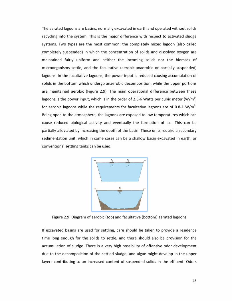
The aerated lagoons are basins, normally excavated in earth and operated without solids
recycling into the system. This is the major difference with respect to activated sludge
systems. Two types are the most common: the completely mixed lagoon (also calle
completely suspended) in which the concentration of solids and dissolved oxygen are
maintained fairly uniform and neither the incoming solids nor the biomass of
microorganisms settle, and the facultative (aerobic
lagoons. In the facultative lagoons, the power input is reduced causing accumulation of
solids in the bottom which undergo anaerobic decomposition; while the upper portions
are maintained aerobic (Figure
lagoons is the power input, which is in the order of 2.5
for aerobic lagoons while the requirements for facultative lagoons are of 0.8
Being open to the atmosphere, the lagoons are exposed to low temperatures which can
cause reduced biological activity and eventually the formation of ice. This can be
partially alleviated by increasing the depth of the basin. These units require a secondary
sedimentation unit, which in some cases can be a shallow basin excavated in earth, or
conventional settling tanks can be used.
Figure 2.9: Diagram of aerobic (top) and facultative (bottom) aerated lagoons
If excavated basins are used for settling, care should be taken to provide a residence
time long enough for the solids to settle, and there should also be provision for the
accumulation of sludge. There is a very high possibility of offensive
due to the decomposition of the settled sludge, and algae might develop in the upper
layers contributing to an increased content of suspended solids in the effluent.
The aerated lagoons are basins, normally excavated in earth and operated without solids
recycling into the system. This is the major difference with respect to activated sludge
systems. Two types are the most common: the completely mixed lagoon (also calle
completely suspended) in which the concentration of solids and dissolved oxygen are
maintained fairly uniform and neither the incoming solids nor the biomass of
microorganisms settle, and the facultative (aerobic-anaerobic or partially suspended)
. In the facultative lagoons, the power input is reduced causing accumulation of
solids in the bottom which undergo anaerobic decomposition; while the upper portions
are maintained aerobic (Figure 2.9). The main operational difference between these
is the power input, which is in the order of 2.5-6 Watts per cubic meter (W/m
for aerobic lagoons while the requirements for facultative lagoons are of 0.8
Being open to the atmosphere, the lagoons are exposed to low temperatures which can
reduced biological activity and eventually the formation of ice. This can be
partially alleviated by increasing the depth of the basin. These units require a secondary
sedimentation unit, which in some cases can be a shallow basin excavated in earth, or
onventional settling tanks can be used.
Diagram of aerobic (top) and facultative (bottom) aerated lagoons
If excavated basins are used for settling, care should be taken to provide a residence
time long enough for the solids to settle, and there should also be provision for the
accumulation of sludge. There is a very high possibility of offensive odor
due to the decomposition of the settled sludge, and algae might develop in the upper
layers contributing to an increased content of suspended solids in the effluent.
45
The aerated lagoons are basins, normally excavated in earth and operated without solids
recycling into the system. This is the major difference with respect to activated sludge
systems. Two types are the most common: the completely mixed lagoon (also called
completely suspended) in which the concentration of solids and dissolved oxygen are
maintained fairly uniform and neither the incoming solids nor the biomass of
anaerobic or partially suspended)
. In the facultative lagoons, the power input is reduced causing accumulation of
solids in the bottom which undergo anaerobic decomposition; while the upper portions
). The main operational difference between these
6 Watts per cubic meter (W/m3)
for aerobic lagoons while the requirements for facultative lagoons are of 0.8-1 W/m3.
Being open to the atmosphere, the lagoons are exposed to low temperatures which can
reduced biological activity and eventually the formation of ice. This can be
partially alleviated by increasing the depth of the basin. These units require a secondary
sedimentation unit, which in some cases can be a shallow basin excavated in earth, or
Diagram of aerobic (top) and facultative (bottom) aerated lagoons
If excavated basins are used for settling, care should be taken to provide a residence
time long enough for the solids to settle, and there should also be provision for the
development
due to the decomposition of the settled sludge, and algae might develop in the upper
layers contributing to an increased content of suspended solids in the effluent. Odors

46
can be minimized by using minimum depths of up to 2 m, while algae production is
reduced with liquid retention time of less than two days.
The solids will also accumulate, all along the aeration basins in the facultative lagoons
and even in comers, or between aeration units in the completely mixed lagoon. These
accumulated solids will, on the whole, decompose in the bottom, but since there is
always a non-biodegradable fraction, a permanent deposit will build up. Therefore,
periodic removal of these accumulated solids becomes necessary.
2.2.3.3 Trickling filters
The trickling filter is the most commonly encountered aerobic attached-growth
biological treatment process used for the removal of organic matter from wastewater. It
consists of a bed of highly permeable medium to which organisms are attached, forming
a biological slime layer, and through which wastewater is percolated. The filter medium
usually consists of rock or plastic packing material. The organic material present in the
wastewater is degraded by adsorption on to the biological slime layer. In the outer
portion of that layer, it is degraded by aerobic microorganisms. As the microorganisms
grow, the thickness of the slime layer increases and the oxygen is depleted before it has
penetrated the full depth of the slime layer. An anaerobic environment is thus
established near the surface of the filter medium. As the slime layer increases in
thickness, the organic matter is degraded before it reaches the microorganisms near the
surface of the medium. Deprived of their external organic source of nourishment, these
microorganisms die and are washed off by the flowing liquid. A new slime layer grows in
their place. This phenomenon is referred to as ‘sloughing’ (Liu and Liptak, 1992 &
Metcalf and Eddy, 1991).
Two types of trickling filters are applied to the treatment of sewage and industrial
wastewater.
i) Sewage treatment trickling filters
Onsite sewage facilities (OSSF) are recognized as viable, low-cost, long-term,
decentralized approaches to sewage treatment if they are planned, designed, installed,
operated and maintained properly.

47
Sewage trickling filters are used in areas not serviced by municipal wastewater
treatment plants (WWTP). They are typically installed in areas where the traditional
septic tank system are failing, cannot be installed due to site limitations, or where
improved levels of treatment are required for environmental benefits such as preventing
contamination of ground water or surface water.
Sites with a high water table, high bedrock, heavy clay, small land area, or which require
minimal site destruction (for example, tree removal) are ideally suited for trickling
filters.
All varieties of sewage trickling filters have low and sometimes intermittent power
consumption. They can be somewhat more expensive than traditional septic tank-leach
field systems, however their use allows for better treatment, a reduction in size of
disposal area, less excavation, and higher density land development.
All sewage trickling filter systems share the same fundamental components:
• a septic tank for fermentation and primary settling of solids
• a filter medium upon which beneficial microbes (biomass, biofilm) are promoted
and developed
• a container which houses the filter medium
• a distribution system for applying wastewater to be treated to the filter medium
• a distribution system for disposal of the treated effluent.
By treating septic tank effluent before it is distributed into the ground, higher treatment
levels are obtained and smaller disposal means such as leach field, shallow pressure
trench or area beds are required.
Systems can be configured for single-pass use where the treated water is applied to the
trickling filter once before being disposed of, or for multi-pass use where a portion of
the treated water is cycled back to the septic tank and re-treated via a closed-loop.
Multi-pass systems result in higher treatment quality and assist in removing Total

Nitrogen (TN) levels by promoting nitrification in the aerobic media bed and
denitrification in the anaerobic septic
Trickling filters differ primarily in the type of filter media used to house the microbial
colonies. Types of media most commonly used include plastic matrix material, open
polyurethane foam, sphagnum peat moss, recycled tires, clinker, gravel
geotextiles. Ideal filter medium optimizes surface area for microbial attachment,
wastewater retention time, allows air flow, resists plugging and does not degrade. Some
residential systems require forced aeration units which will increase maint
operational costs.
Third-party verification of trickling filters has proven them to be a reliable alternative to
septic systems with increased levels of treatment performance and nitrogen removal.
Typical effluent quality parameters are Biochem
suspended solids (TSS), Total Kjeldahl Nitrogen (TKN), and fecal coliforms.
Figure 2.10
ii) Industrial wastewater treatment trickl
Wastewaters from a variety of
Such industrial wastewater trickling filters consist of two types:
• Large tanks or concrete enclosures filled with plastic packing or other media.
Nitrogen (TN) levels by promoting nitrification in the aerobic media bed and
denitrification in the anaerobic septic tank.
Trickling filters differ primarily in the type of filter media used to house the microbial
colonies. Types of media most commonly used include plastic matrix material, open
polyurethane foam, sphagnum peat moss, recycled tires, clinker, gravel
geotextiles. Ideal filter medium optimizes surface area for microbial attachment,
wastewater retention time, allows air flow, resists plugging and does not degrade. Some
residential systems require forced aeration units which will increase maint
party verification of trickling filters has proven them to be a reliable alternative to
septic systems with increased levels of treatment performance and nitrogen removal.
Typical effluent quality parameters are Biochemical Oxygen Demand (BOD), Total
suspended solids (TSS), Total Kjeldahl Nitrogen (TKN), and fecal coliforms.
2.10: A typical complete trickling filter system.
Industrial wastewater treatment trickling filters
Wastewaters from a variety of industrial processes have been treated in trickling filters.
Such industrial wastewater trickling filters consist of two types:
Large tanks or concrete enclosures filled with plastic packing or other media.
48
Nitrogen (TN) levels by promoting nitrification in the aerobic media bed and
Trickling filters differ primarily in the type of filter media used to house the microbial
colonies. Types of media most commonly used include plastic matrix material, open-cell
polyurethane foam, sphagnum peat moss, recycled tires, clinker, gravel, sand and
geotextiles. Ideal filter medium optimizes surface area for microbial attachment,
wastewater retention time, allows air flow, resists plugging and does not degrade. Some
residential systems require forced aeration units which will increase maintenance and
party verification of trickling filters has proven them to be a reliable alternative to
septic systems with increased levels of treatment performance and nitrogen removal.
ical Oxygen Demand (BOD), Total
industrial processes have been treated in trickling filters.
Large tanks or concrete enclosures filled with plastic packing or other media.

• Vertical towers filled with plastic packing or o
The availability of inexpensive plastic tower packings has led to their use as trickling
filter beds in tall towers, some as high as 20 meters.
The treated water effluent from industrial wastewater trickling filters is very often
subsequently processed in a clarifier
microbial slime layer attached to the trickling filter media
Currently, some of the latest trickl
are essentially trickling filters consisting of plastic media in
inject air at the bottom of the vessels, with e
wastewater.
After passing through the filter, the treated liquid is collected in an under drain sy
together with any biological solids that have become detached from the medium (figure
2.11). The collected liquid then passes to a settling tank where the solids are separated
from the treated wastewater. A portion of the liquid collected in the unde
or the settled effluent is recycled to dilute the strength of the incoming wastewater and
to maintain the biological slime layer in moist condition (figure
Figure 2.1
Vertical towers filled with plastic packing or other media.
The availability of inexpensive plastic tower packings has led to their use as trickling
filter beds in tall towers, some as high as 20 meters.
The treated water effluent from industrial wastewater trickling filters is very often
subsequently processed in a clarifier-settler to remove the sludge that sloughs off the
microbial slime layer attached to the trickling filter media.
Currently, some of the latest trickling filter technology involves aerated biofilters which
filters consisting of plastic media in vessels using blowers to
air at the bottom of the vessels, with either downflow or upflow of the
After passing through the filter, the treated liquid is collected in an under drain sy
together with any biological solids that have become detached from the medium (figure
). The collected liquid then passes to a settling tank where the solids are separated
from the treated wastewater. A portion of the liquid collected in the under drain system
or the settled effluent is recycled to dilute the strength of the incoming wastewater and
to maintain the biological slime layer in moist condition (figure 2.12).
2.11: Cutaway view of a trickling filter.
49
The availability of inexpensive plastic tower packings has led to their use as trickling
The treated water effluent from industrial wastewater trickling filters is very often
settler to remove the sludge that sloughs off the
filter technology involves aerated biofilters which
vessels using blowers to
ither downflow or upflow of the
After passing through the filter, the treated liquid is collected in an under drain system,
together with any biological solids that have become detached from the medium (figure
). The collected liquid then passes to a settling tank where the solids are separated
r drain system
or the settled effluent is recycled to dilute the strength of the incoming wastewater and

Figure 2.12
Table 2.8: Advantages and disadvantages of trickling filter
Advantages
Good quality (80-90% BOD5 removal) for 2
stage efficiency could reach 95%
Moderate operating costs (lower than
activated sludge)
Withstands shock loads better than other
biological processes
2.2.3.4 Rotating biological contactors
A rotating biological contractor (RBC) is an attached
consists of one or more basins in which large closely spaced circular disks mounted on
horizontal shafts rotate slowly through wastewater (figure
made of high-density polystyrene or polyvinyl chloride (PVC), are partially submerged in
the wastewater, so that a bacterial slime layer forms on their wetted surfaces. As the
disks rotate, the bacteria are exposed alternately to wastewater, from which
adsorb organic matter, and to air, from which they absorb oxygen. The rotary movement
also allows excess bacteria to be removed from the surfaces of the disks and maintains a
suspension of sloughed biological solids. A final clarifier is needed to rem
solids. Organic matter is degraded by means of mechanisms similar to those operating in
the trickling filters process. Partially submerged RBCs are used for carbonaceous BOD
removal, combined carbon oxidation and nitrification, and nitrificati
effluents. Completely submerged RBCs are used for denitrification
1991).
2: Typical flow diagram for trickling filters
Table 2.8: Advantages and disadvantages of trickling filter
Disadvantages
removal) for 2-
stage efficiency could reach 95%
High capital costs
Moderate operating costs (lower than Clogging of distributors or beds
Withstands shock loads better than other Snail, mosquito and insect problems
Rotating biological contactors
A rotating biological contractor (RBC) is an attached-growth biological process that
consists of one or more basins in which large closely spaced circular disks mounted on
horizontal shafts rotate slowly through wastewater (figure 2.13). The disks, which a
density polystyrene or polyvinyl chloride (PVC), are partially submerged in
the wastewater, so that a bacterial slime layer forms on their wetted surfaces. As the
disks rotate, the bacteria are exposed alternately to wastewater, from which
adsorb organic matter, and to air, from which they absorb oxygen. The rotary movement
also allows excess bacteria to be removed from the surfaces of the disks and maintains a
suspension of sloughed biological solids. A final clarifier is needed to remove sloughed
solids. Organic matter is degraded by means of mechanisms similar to those operating in
the trickling filters process. Partially submerged RBCs are used for carbonaceous BOD
removal, combined carbon oxidation and nitrification, and nitrification of secondary
effluents. Completely submerged RBCs are used for denitrification (Metcalf and Eddy,
50
Clogging of distributors or beds
Snail, mosquito and insect problems
growth biological process that
consists of one or more basins in which large closely spaced circular disks mounted on
). The disks, which are
density polystyrene or polyvinyl chloride (PVC), are partially submerged in
the wastewater, so that a bacterial slime layer forms on their wetted surfaces. As the
disks rotate, the bacteria are exposed alternately to wastewater, from which they
adsorb organic matter, and to air, from which they absorb oxygen. The rotary movement
also allows excess bacteria to be removed from the surfaces of the disks and maintains a
ove sloughed
solids. Organic matter is degraded by means of mechanisms similar to those operating in
the trickling filters process. Partially submerged RBCs are used for carbonaceous BOD
on of secondary
(Metcalf and Eddy,

Figure 2.13: RBC system configuration
Figure 2.14: Schematic diagram of a typical rotating biological contactor (RBC). The
treated effluent clarifier/settler is not included in the diagram.
A typical arrangement of RBCs is shown in figure
divided into a series of indepen
single basin or separate basins arranged in stages. Compartmentalization creates a plug
flow pattern, increasing overall removal efficiency.
It also promotes a variety of conditions where different orga
degrees. As the wastewater flows through the compartments, each subsequent stage
receives influent with a lower organic content than the previous stage; the system thus
enhances organic removal.
RBC system configuration (Source: Qasim, 1999).
Schematic diagram of a typical rotating biological contactor (RBC). The
treated effluent clarifier/settler is not included in the diagram.
A typical arrangement of RBCs is shown in figure 2.15. In general, RBC systems are
divided into a series of independent stages or compartments by means of baffles in a
single basin or separate basins arranged in stages. Compartmentalization creates a plug
flow pattern, increasing overall removal efficiency.
It also promotes a variety of conditions where different organisms can flourish to varying
degrees. As the wastewater flows through the compartments, each subsequent stage
receives influent with a lower organic content than the previous stage; the system thus
51
Schematic diagram of a typical rotating biological contactor (RBC). The
treated effluent clarifier/settler is not included in the diagram.
. In general, RBC systems are
dent stages or compartments by means of baffles in a
single basin or separate basins arranged in stages. Compartmentalization creates a plug-
nisms can flourish to varying
degrees. As the wastewater flows through the compartments, each subsequent stage
receives influent with a lower organic content than the previous stage; the system thus

Figure 2.1
Table 2.9: Advantages and disadvantages of rotating biological contactor (RBC)
Advantages
Short contact periods
Handles a wide range of flows
Easily separates biomass from waste
stream
Low operating costs
Short retention time
Low sludge production
Low power requirements
Low sludge production and excellent
control
2.2.3.5 Stabilization ponds
A stabilization pond is a relatively shallow body of wastewater contained in an earthen
basin, using a completely mixed biological process without solids return. Mixing may be
either natural (wind, heat or fermentation) or induced (mechanical or diffused a
Stabilization ponds are usually classified, on the basis of the nature of the biological
activity that takes place in them, as aerobic, anaerobic, or aerobic
2.10). Aerobic ponds are used primarily for the treatment of soluble o
effluents from wastewater treatment plants. Aerobic
the most common type and have been used to treat domestic wastewater and a wide
variety of industrial wastes. Anaerobic ponds, for their part, are parti
bringing about rapid stabilization of strong concentrations of organic wastes. Aerobic
and facultative ponds are biologically complex. The bacterial population oxidizes organic
matter, producing ammonia, carbon dioxide, sulfates, water
Figure 2.15: Typical flow diagram for RBC units.
Table 2.9: Advantages and disadvantages of rotating biological contactor (RBC)
Disadvantages
Need for covering units installed in cold
climate to protect against freezing
flows Shaft bearings and mechanical drive units
require frequent maintenance
Easily separates biomass from waste
excellent process
Stabilization ponds
A stabilization pond is a relatively shallow body of wastewater contained in an earthen
basin, using a completely mixed biological process without solids return. Mixing may be
either natural (wind, heat or fermentation) or induced (mechanical or diffused a
Stabilization ponds are usually classified, on the basis of the nature of the biological
activity that takes place in them, as aerobic, anaerobic, or aerobic- anaerobic (table
10). Aerobic ponds are used primarily for the treatment of soluble organic wastes and
effluents from wastewater treatment plants. Aerobic-anaerobic (facultative) ponds are
the most common type and have been used to treat domestic wastewater and a wide
variety of industrial wastes. Anaerobic ponds, for their part, are particularly effective in
bringing about rapid stabilization of strong concentrations of organic wastes. Aerobic
and facultative ponds are biologically complex. The bacterial population oxidizes organic
matter, producing ammonia, carbon dioxide, sulfates, water and other end products,
52
Table 2.9: Advantages and disadvantages of rotating biological contactor (RBC)
Need for covering units installed in cold
climate to protect against freezing
Shaft bearings and mechanical drive units
require frequent maintenance
A stabilization pond is a relatively shallow body of wastewater contained in an earthen
basin, using a completely mixed biological process without solids return. Mixing may be
either natural (wind, heat or fermentation) or induced (mechanical or diffused aeration).
Stabilization ponds are usually classified, on the basis of the nature of the biological
anaerobic (table
rganic wastes and
anaerobic (facultative) ponds are
the most common type and have been used to treat domestic wastewater and a wide
cularly effective in
bringing about rapid stabilization of strong concentrations of organic wastes. Aerobic
and facultative ponds are biologically complex. The bacterial population oxidizes organic
and other end products,

which are subsequently used by algae during daylight to produce oxygen. Bacteria then
use this supplemental oxygen and the oxygen provided by wind action to break down
the remaining organic matter. Wastewater retention time ranges
days. This is a treatment process that is very commonly found in rural areas because of
its low construction and operating costs. Figure
stabilization ponds (Liu and Liptak, 1992
Figure 2.16: Typical flow diagram for stabilization ponds
Table 2.10: Types and applications of stabilization ponds
Type of pond Common name
Aerobic Low-rate pond
High-rate pond
Maturation
pond
Aerobic-
anaerobic
(supplemental
aeration)
Facultative
pond with
aeration
which are subsequently used by algae during daylight to produce oxygen. Bacteria then
use this supplemental oxygen and the oxygen provided by wind action to break down
the remaining organic matter. Wastewater retention time ranges between 30 and 120
days. This is a treatment process that is very commonly found in rural areas because of
its low construction and operating costs. Figure 2.16 presents a typical flow diagram for
Liu and Liptak, 1992).
: Typical flow diagram for stabilization ponds.
ypes and applications of stabilization ponds
Common name Characteristics Application
rate pond
Designed to maintain aerobic
conditions throughout the liquid
depth
Designed to optimize the production
of algal cell tissue and achieve high
yields of harvestable proteins
Similar to low-rate ponds but very
lightly loaded
Treatment of soluble organic
wastes and secondary
effluents
Nutrient removal, treatment
of soluble organic wastes,
conversion of wastes
Used for polishing effluents
from conventional secondary
treatment processes such as Deeper than high-rate pond; aeration
and photosynthesis provide oxygen
for aerobic stabilization in upper
layers. Lower layers are facultative.
Treatment of screened
untreated or
wastewater or industrial
wastes.
53
which are subsequently used by algae during daylight to produce oxygen. Bacteria then
use this supplemental oxygen and the oxygen provided by wind action to break down
between 30 and 120
days. This is a treatment process that is very commonly found in rural areas because of
presents a typical flow diagram for
Treatment of soluble organic
wastes and secondary
Nutrient removal, treatment
of soluble organic wastes,
conversion of wastes
Used for polishing effluents
from conventional secondary
treatment processes such as Treatment of screened
untreated or primary settled
wastewater or industrial

54
Table 2.10: Types and applications of stabilization ponds (Continued)
Type of pond Common name Characteristics Application
Aerobic-
anaerobic
(oxygen from
algae)
Facultative
pond
As above, except without
supplemental aeration.
Photosynthesis and surface
reaeration provide oxygen for upper
layers.
Treatment of screened
untreated or primary settled
wastewater or industrial
wastes.
Anaerobic Anaerobic
lagoon,
anaerobic
Anaerobic conditions prevail
throughout; usually followed by
aerobic or facultative ponds.
Treatment of municipal
wastewater and industrial
wastes.
Anaerobic
followed by
aerobic-
anaerobic
Pond system Combination of pond types described
above. Aerobic-anaerobic ponds may
be followed by an aerobic pond.
Recirculation frequently used from
aerobic to anaerobic ponds.
Complete treatment of
municipal wastewater and
industrial wastes with high
bacterial removal.
Source: Adapted from Metcalf and Eddy, 1991.
Table 2.11: Advantages and disadvantages of stabilization ponds
Advantages Disadvantages
Anaerobic stabilization ponds
Does not require external energy Occupies open and permanent space
Removes heavy metals as insoluble metal
sulphides
Can release foul odor
Simple in construction Can contribute to mosquito breeding
Flexible degree of treatment
Low maintenance
Aerobic/Facultative stabilization pond
Simple construction Large permanent space requirement
High pathogen removal rate Can lead to mosquito breeding and release
odor if too small
Reliable if properly designed Algae in the pond can increase effluent
BOD
Can generate revenue through fish farming
2.2.3.6 Completely mixed anaerobic digestion
Anaerobic digestion involves the biological conversion of organic and inorganic matter in
the absence of molecular oxygen to a variety of end-products including methane and
carbon dioxide. A consortium of anaerobic organisms work together to degrade the

organic sludges and wastes in three steps, consisting of hydrolysis of high
mass compounds, acidogenesis and methanogenesis.
Figure 2.17: Diagram of
The process takes place in an airtight reactor. Sludge is intro
intermittently and retained in the reactor for varying periods of time. After withdrawal
from the reactor, whether continuous or intermittent, the stabilized sludge is reduced in
organic and pathogen content and is nonputrescible. The
anaerobic digesters are standard rate and high
process, the contents of the digester are usually unheated and unmixed, and are
retained for a period ranging from 30 to 60 days. In the high
contents of the digester are heated and mixed completely, and are retained, typically,
for a period of 15 days or less. A combination of these two basic processes is known as
the two-stage process, and is used to separate the d
liquor. However, additional digestion and gas production may occur
1991).
Anaerobic digesters are commonly used for the treatment of sludge and wastewater
with high organic content. The disadvantage
compared to aerobic treatment, stem directly from the slow growth rate of
methanogenic bacteria. A slow growth rate requires a relatively long retention time in
the digester for adequate waste stabilization to
means that only a small portion of the degradable organic matter is synthesized into
new cells. Another advantage of this type of system is the production of methane gas,
ganic sludges and wastes in three steps, consisting of hydrolysis of high
mass compounds, acidogenesis and methanogenesis.
: Diagram of an anaerobic digestion process.
The process takes place in an airtight reactor. Sludge is introduced continuously or
intermittently and retained in the reactor for varying periods of time. After withdrawal
from the reactor, whether continuous or intermittent, the stabilized sludge is reduced in
organic and pathogen content and is nonputrescible. The two most widely used types of
anaerobic digesters are standard rate and high-rate. In the standard-rate digestion
process, the contents of the digester are usually unheated and unmixed, and are
retained for a period ranging from 30 to 60 days. In the high-rate digestion process, the
contents of the digester are heated and mixed completely, and are retained, typically,
for a period of 15 days or less. A combination of these two basic processes is known as
stage process, and is used to separate the digested solids from the supernatant
liquor. However, additional digestion and gas production may occur (Metcalf and Eddy,
Anaerobic digesters are commonly used for the treatment of sludge and wastewater
The disadvantages and advantages of a system of this kind, as
compared to aerobic treatment, stem directly from the slow growth rate of
methanogenic bacteria. A slow growth rate requires a relatively long retention time in
the digester for adequate waste stabilization to occur; however, that same slow growth
means that only a small portion of the degradable organic matter is synthesized into
new cells. Another advantage of this type of system is the production of methane gas,
55
ganic sludges and wastes in three steps, consisting of hydrolysis of high-molecular-
duced continuously or
intermittently and retained in the reactor for varying periods of time. After withdrawal
from the reactor, whether continuous or intermittent, the stabilized sludge is reduced in
two most widely used types of
rate digestion
process, the contents of the digester are usually unheated and unmixed, and are
rate digestion process, the
contents of the digester are heated and mixed completely, and are retained, typically,
for a period of 15 days or less. A combination of these two basic processes is known as
igested solids from the supernatant
(Metcalf and Eddy,
Anaerobic digesters are commonly used for the treatment of sludge and wastewaters
s and advantages of a system of this kind, as
compared to aerobic treatment, stem directly from the slow growth rate of
methanogenic bacteria. A slow growth rate requires a relatively long retention time in
occur; however, that same slow growth
means that only a small portion of the degradable organic matter is synthesized into
new cells. Another advantage of this type of system is the production of methane gas,

56
which can be used as a fuel source, if produced in sufficient quantities. Furthermore, the
system produces a well-stabilized sludge, which can be safely disposed of in a sanitary
landfill after drying or dewatering. On the other hand, the fact that high temperatures
are required for adequate treatment is a major drawback.
2.2.3.7 Biological nutrient removal
Nitrogen and phosphorus are the principal nutrients of concern in wastewater
discharges. Discharges containing nitrogen and phosphorus may accelerate the
eutrophication of lakes and reservoirs and stimulate the growth of algae and rooted
aquatic plants in shallow streams. Significant concentrations of nitrogen may have other
adverse effects as well: depletion of dissolved oxygen in receiving waters, toxicity to
aquatic life, adverse impact on chlorine disinfection efficiency, creation of a public
health hazard, and wastewater that is less suitable for reuse. Nitrogen and phosphorus
can be removed by physical, chemical and biological methods. Biological removal of
these nutrients is described below.
2.2.3.7.1 Nitrification-denitrification
Nitrification is the first step in the removal of nitrogen by means of this process.
Biological nitrification is the work of two bacterial genera: Nitrosomonas, which oxidize
ammonia to the intermediate product nitrite, and Nitrobacter, which convert nitrite to
nitrate. Nitrifying bacteria are sensitive organisms and are extremely susceptible to a
wide variety of inhibitors such as high concentrations of ammonia and nitrous acid, low
DO levels (< 1 mg/L), pH outside the optimal range (7.5-8.6), and so on. Nitrification can
be achieved through both suspended growth and attached-growth processes. In
suspended-growth processes, nitrification is brought about either in the same reactor
that is used for carbonaceous BOD removal, or in a separate suspended-growth reactor
following a conventional activated sludge treatment process. Ammonia is oxidized to
nitrate with either air or high purity oxygen. Similarly, nitrification in an attached-growth
system may be brought about either in the same attached growth reactor that is used
for carbonaceous BOD removal or in a separate reactor. Trickling filters, rotating
biological contactors and packed towers can be used for nitrifying systems.

57
Denitrification involves the removal of nitrogen in the form of nitrate by conversion to
nitrogen gas under anoxic conditions. In denitrifying systems, DO is a critical parameter.
Its presence suppresses the enzyme system needed for denitrification. The optimal pH
lies between 7 and 8. Denitrification can be achieved through both suspended and
attached growth processes. Suspended-growth denitrification takes place in a plug-flow
type of activated-sludge system. An external carbon source is usually necessary for
micro-organism cell synthesis, since the nitrified effluent is low in carbonaceous matter.
Some denitrification systems use the incoming wastewater for this purpose. A nitrogen-
gas-stripped reactor should precede the denitrification clarifier because nitrogen gas
hinders the settling of the mixed liquor. Attached-growth denitrification takes place in a
column reactor containing stone or one of a number of synthetic media upon which the
bacteria grow. Periodic backwashing and an external carbon source are necessary in a
system of this kind.
2.2.3.7.2 Phosphorus removal
Phosphorus appears in water as orthophosphate (PO4), polyphosphate (P2O7), and
organically bound phosphorus. Microbes utilize phosphorus during cell synthesis and
energy transport. As a result, 10 to 30 percent of all influent phosphorus is removed
during secondary biological treatment. More phosphorus can be removed if one of a
number of specially developed biological phosphorus removal processes is used. These
processes are based on the exposure of microbes in an activated-sludge system to
alternating anaerobic and aerobic conditions. This stresses the microorganisms, so that
their uptake of phosphorus exceeds normal levels. Typical biological processes used for
phosphorus removal are the proprietary A/O process, the proprietary PhoStrip process,
and the sequencing batch reactor (SBR) process (figure 2.18).
The A/O process is a single-sludge suspended growth system that combines aerobic and
anaerobic sections in sequence. Settled sludge is returned to the influent end of the
reactor and mixed with the incoming wastewater. In the PhoStrip process, a portion of
the return activated sludge from the secondary biological treatment process is diverted
to an anaerobic phosphorus stripping tank. There, phosphorus is released into the
supernatant, which is subsequently treated with lime or some other coagulant. The
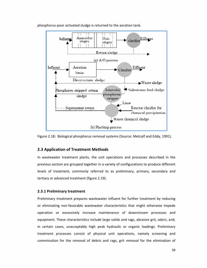
phosphorus-poor activated sludge is returned to the aeration tank.
Figure 2.18: Biological phosphorus removal systems
2.3 Application of Treatment
In wastewater treatment plants, the unit operations and processes described in the
previous section are grouped together in a variety of configurations to produce different
levels of treatment, commonly referred to as prelim
tertiary or advanced treatment (figure
2.3.1 Preliminary treatment
Preliminary treatment prepares wastewater influent for further treatment by reducing
or eliminating non-favorable wastewater characteristics that might
operation or excessively increase maintenance of downstream processes and
equipment. These characteristics include large solids and rags, abrasive grit, odors, and,
in certain cases, unacceptably high peak hydraulic or organic loadings. P
treatment processes consist of physical unit operations, namely screening and
comminution for the removal of debris and rags, grit removal for the elimination of
poor activated sludge is returned to the aeration tank.
Biological phosphorus removal systems (Source: Metcalf and Eddy, 1991).
reatment Methods
In wastewater treatment plants, the unit operations and processes described in the
previous section are grouped together in a variety of configurations to produce different
levels of treatment, commonly referred to as preliminary, primary, secondary and
tertiary or advanced treatment (figure 2.19).
Preliminary treatment
Preliminary treatment prepares wastewater influent for further treatment by reducing
favorable wastewater characteristics that might otherwise impede
operation or excessively increase maintenance of downstream processes and
equipment. These characteristics include large solids and rags, abrasive grit, odors, and,
in certain cases, unacceptably high peak hydraulic or organic loadings. P
treatment processes consist of physical unit operations, namely screening and
comminution for the removal of debris and rags, grit removal for the elimination of
58
: Metcalf and Eddy, 1991).
In wastewater treatment plants, the unit operations and processes described in the
previous section are grouped together in a variety of configurations to produce different
inary, primary, secondary and
Preliminary treatment prepares wastewater influent for further treatment by reducing
otherwise impede
operation or excessively increase maintenance of downstream processes and
equipment. These characteristics include large solids and rags, abrasive grit, odors, and,
in certain cases, unacceptably high peak hydraulic or organic loadings. Preliminary
treatment processes consist of physical unit operations, namely screening and
comminution for the removal of debris and rags, grit removal for the elimination of

59
coarse suspended matter, and flotation for the removal of oil and grease. Other
preliminary treatment operations include flow equalization, septage handling, and odor
control methods.
2.3.2 Primary treatment
Primary treatment involves the partial removal of suspended solids and organic matter
from the wastewater by means of physical operations such as screening and
sedimentation. Pre-aeration or mechanical flocculation with chemical additions can be
used to enhance primary treatment. Primary treatment acts as a precursor for
secondary treatment. It is aimed mainly at producing a liquid effluent suitable for
downstream biological treatment and separating out solids as a sludge that can be
conveniently and economically treated before ultimate disposal. The effluent from
primary treatment contains a good deal of organic matter and is characterized by a
relatively high BOD.
2.3.3 Secondary treatment
The purpose of secondary treatment is the removal of soluble and colloidal organics and
suspended solids that have escaped the primary treatment. This is typically done
through biological processes, namely treatment by activated sludge, fixed-film reactors,
or lagoon systems and sedimentation.
2.3.4 Tertiary/advanced wastewater treatment
Tertiary treatment goes beyond the level of conventional secondary treatment to
remove significant amounts of nitrogen, phosphorus, heavy metals, biodegradable
organics, bacteria and viruses. In addition to biological nutrient removal processes, unit
operations frequently used for this purpose include chemical coagulation, flocculation
and sedimentation, followed by filtration and activated carbon. Less frequently used
processes include ion exchange and reverse osmosis for specific ion removal or for
dissolved solids reduction.

60
Biological
process
Chlorine
contact
chambe
Influent Effluent
Cl2
Screens &
Communition
Grit removal
Recycle
Waste sludge
2.4 Natural Treatment Systems
Natural systems for wastewater treatment are designed to take advantage of the
physical, chemical, and biological processes that occur in the natural environment when
water, soil, plants, microorganisms and the atmosphere interact (Metcalf and Eddy,
1991). Natural treatment systems include land treatment, floating aquatic plants and
constructed wetlands. All natural treatment systems are preceded by some form of
mechanical pretreatment for the removal of gross solids. Where sufficient land suitable
for the purpose is available, these systems can often be the most cost effective option in
terms of both construction and operation. They are frequently well suited for small
communities and rural areas (Reed et al., 1988).
Figure 2.19: Various treatment levels in a wastewater treatment plant flow diagram.
2.4.1 Land treatment
Land treatment is the controlled application of wastewater to the land at rates
compatible with the natural physical, chemical and biological processes that occur on
Secondary
settling
Primary
settling
Effluent
filtration Mixer
Tertiary treatment
Secondary treatment
Primary treatment
Preliminary treatment
Offline flow
equalization
Backwash wastewater
Sludge processing
facility
Flotation
thickening
Backwash
water
storage

61
and in the soil. The three main types of land treatment systems used are slow rate (SR),
overflow (OF), and rapid infiltration (RI) systems.
2.4.1.1 Slow rate
SR systems are the predominant form of land treatment for municipal and industrial
wastewater. This technology incorporates wastewater treatment, water reuse, crop
utilization of nutrients and wastewater disposal. It involves the application of
wastewater to vegetated land by means of various techniques, including sprinkling
methods or surface techniques such as graded-border and furrow irrigation. Water is
applied intermittently (every 4 to 10 days) to maintain aerobic conditions in the soil
profile. The applied water is either consumed through evapotranspiration or percolated
vertically and horizontally through the soil system. Any surface runoff is collected and
reapplied to the system. Treatment occurs as the wastewater percolates through the
soil profile (table 2.12). In most cases, the percolate will enter the underlying
groundwater, or it may be intercepted by natural surface waters or recovered by means
of underdrains or recovery wells (Metcalf and Eddy, 1991 & Reed et al., 1988).
Table 2.12: Mechanisms of wastewater constituent removal by SR systems
Parameter Removal mechanism
BOD Soil adsorption and bacterial oxidation
SS Filtration through the soil
Nitrogen Crop uptake, denitrification, ammonia volatilization, soil storage
Phosphorus Chemical immobilization (precipitation and adsorption), plant uptake
Metals Soil adsorption, precipitation, ion exchange, complexation
Pathogens Soil filtration, adsorption, desiccation, radiation, predation, exposure to
other adverse
Trace
organics
Photodecomposition, volatilization, sorption, degradation
Source: Reed et al., 1988.
SR systems can be classified into two types, Type 1 and Type 2, based on design
objectives. Type 1 systems are designed with wastewater treatment itself, rather than
crop production, as their main objective. Accordingly, in systems of this kind, the

62
maximum possible amount of water is applied per unit land area. Type 2 SR systems, in
contrast, are designed mainly with a view to water reuse for crop production, and
consequently the amount of water applied in a system of this kind is just enough to
satisfy the irrigation requirements of the crop being grown. SR systems have the highest
treatment potential of all natural treatment systems.
2.4.1.2 Rapid infiltration
Rapid infiltration (RI) is the most intensive of all land treatment methods. Relatively high
hydraulic and organic loadings are applied intermittently to shallow infiltration or
spreading basins (figure 2.20). The RI process uses the soil matrix for physical, chemical,
and biological treatment. Physical straining and filtering occur at the soil surface and
within the soil matrix. Chemical precipitation, ion exchange and adsorption occur as the
water percolates through the soil. Biological oxidation, assimilation and reduction occur
within the top few feet of the soil. Vegetation is not applied in systems of this kind. The
RI system is designed to meet several performance objectives including the following:
(a) Recharge of streams by interception of groundwater;
(b) Recovery of water by wells or underdrains, with subsequent reuse or discharge;
(c) Groundwater recharge;
(d) Temporary storage of renovated water in the local aquifer (Sanks and Asano
1976 & Metcalf and Eddy, 1991).
2.4.1.3 Overland flow
Overland flow (OF) is a treatment process in which wastewater is treated as it flows
down a network of vegetated sloping terraces. Wastewater is applied intermittently to
the top portion of each terrace and flows down the terrace to a runoff collection
channel at the bottom of the slope. Application techniques include high-pressure
sprinklers, low-pressure sprays, or surface methods such as gated pipes. OF is normally
used with relatively impermeable surface soils, since, in contrast to SR and RI systems,
infiltration through the soil is limited. The effluent wastewater undergoes a variety of
physical, chemical and biological treatment mechanisms as it proceeds along surface
runoff path. Overland flow systems can be designed for secondary treatment, advanced
secondary treatment or nutrient removal, depending on user requirements.

Figure 2.20: Rapid infiltration
2.4.2 Constructed wetlands
Wetlands are inundated land areas with water depths typically less than 2 ft (0.6 m) that
support the growth of emergent plants such as cattail, bulrush, reeds and sedges. The
vegetation provides surfaces for the attachment of bacteria films, aids in the filtration
and adsorption of wastewater constituents, transfers oxygen into the water column, and
controls the growth of algae by restricting the penetration of sunlight. Two typ
constructed wetlands have been developed for wastewater treatment, namely free
water surface (FWS) systems, and subsurface flow systems (SFS)
& Reed et al., 1988).
2.4.2.1 Free water surface systems
FWS systems consist of parallel shallow basins ranging from 0.3 to 2 feet (0.1
or channels with relatively impermeable bottom soil or subsurface barrier and emergent
vegetation (figure 2.21). As a rule, pre
treated as it flows through the stems and roots of the emergent vegetation.
Figure 2.21: Free water surface system
Rapid infiltration treatment system (Source: Metcalf and Eddy, 1991)
Constructed wetlands
Wetlands are inundated land areas with water depths typically less than 2 ft (0.6 m) that
support the growth of emergent plants such as cattail, bulrush, reeds and sedges. The
egetation provides surfaces for the attachment of bacteria films, aids in the filtration
and adsorption of wastewater constituents, transfers oxygen into the water column, and
controls the growth of algae by restricting the penetration of sunlight. Two typ
constructed wetlands have been developed for wastewater treatment, namely free
water surface (FWS) systems, and subsurface flow systems (SFS) (Sanks and Asano 1976
Free water surface systems
FWS systems consist of parallel shallow basins ranging from 0.3 to 2 feet (0.1
or channels with relatively impermeable bottom soil or subsurface barrier and emergent
). As a rule, pre-clarified wastewater is applied continuously to be
treated as it flows through the stems and roots of the emergent vegetation.
: Free water surface system (Source: Qasim, 1999).
63
: Metcalf and Eddy, 1991).
Wetlands are inundated land areas with water depths typically less than 2 ft (0.6 m) that
support the growth of emergent plants such as cattail, bulrush, reeds and sedges. The
egetation provides surfaces for the attachment of bacteria films, aids in the filtration
and adsorption of wastewater constituents, transfers oxygen into the water column, and
controls the growth of algae by restricting the penetration of sunlight. Two types of
constructed wetlands have been developed for wastewater treatment, namely free
(Sanks and Asano 1976
FWS systems consist of parallel shallow basins ranging from 0.3 to 2 feet (0.1-0.6 meter)
or channels with relatively impermeable bottom soil or subsurface barrier and emergent
nuously to be
treated as it flows through the stems and roots of the emergent vegetation.
: Qasim, 1999).

2.4.2.2 Subsurface flow systems
SFSs consist of beds or channels filled with gravel, sand, or other
planted with emergent vegetation (figure
horizontally through the media
secondary or advanced levels of treatment.
Figure 2.22: Subsurface flow
2.4.3 Floating aquatic plants
This system is similar to the FWS system except that the plants used are of the floating
type, such as hyacinths and duckweeds (figure 2
the case of wetland systems, ranging from 1.6 to 6.0 feet (0.5
plants shield the water from sunlight and reduce the growth of algae. Systems of this
kind have been effective in reducing BOD, nitrogen, metals and trace organics and in
removing algae from lagoons and stabilization pond effluents. Supplementary aeration
has been used with floating plant systems to increase treatment capacity and to
maintain the aerobic conditions necessary for the biological control of mosquitoes
(Metcalf and Eddy, 1991).
Figure 2.23: Floating aquatic plants system
Subsurface flow systems
SFSs consist of beds or channels filled with gravel, sand, or other permeable media
planted with emergent vegetation (figure 2.22). Wastewater is treated as it flows
horizontally through the media-plant filter. Systems of this kind are designed for
secondary or advanced levels of treatment.
: Subsurface flow system (Source: Qasim, 1999).
Floating aquatic plants
This system is similar to the FWS system except that the plants used are of the floating
type, such as hyacinths and duckweeds (figure 2.23). Water depths are greater than in
systems, ranging from 1.6 to 6.0 feet (0.5-1.8 meters). The floating
plants shield the water from sunlight and reduce the growth of algae. Systems of this
kind have been effective in reducing BOD, nitrogen, metals and trace organics and in
from lagoons and stabilization pond effluents. Supplementary aeration
has been used with floating plant systems to increase treatment capacity and to
maintain the aerobic conditions necessary for the biological control of mosquitoes
: Floating aquatic plants system (Source: Metcalf and Eddy, 1991).
64
permeable media
). Wastewater is treated as it flows
plant filter. Systems of this kind are designed for
This system is similar to the FWS system except that the plants used are of the floating
). Water depths are greater than in
1.8 meters). The floating
plants shield the water from sunlight and reduce the growth of algae. Systems of this
kind have been effective in reducing BOD, nitrogen, metals and trace organics and in
from lagoons and stabilization pond effluents. Supplementary aeration
has been used with floating plant systems to increase treatment capacity and to
maintain the aerobic conditions necessary for the biological control of mosquitoes
: Metcalf and Eddy, 1991).

65
2.5 Recent techniques
2.5.1 Sequencing batch reactor
Sequencing batch reactors (SBR) or sequential batch reactors are industrial processing
tanks for the treatment of wastewater. SBR reactors treat waste water such as sewage
or output from anaerobic digesters or mechanical biological treatment facilities in
batches. Oxygen is bubbled through the waste water to reduce biochemical oxygen
demand (BOD) and chemical oxygen demand (COD) to make suitable for discharge into
sewers or for use on land.
While there are several configurations of SBRs the basic process is similar. The
installation consists of at least two identically equipped tanks with a common inlet,
which can be switched between them. The tanks have a “flow through” system, with
raw wastewater (influent) coming in at one end and treated water (effluent) flowing out
the other. While one tank is in settle/decant mode the other is aerating and filling. At
the inlet is a section of the tank known as the bio-selector. This consists of a series of
walls or baffles which direct the flow either from side to side of the tank or under and
over consecutive baffles. This helps to mix the incoming Influent and the returned
activated sludge, beginning the biological digestion process before the liquor enters the
main part of the tank.
There are four stages to treatment, fill, aeration, settling and decanting. The aeration
stage involves adding air to the mixed solids and liquid either by the use of fixed or
floating mechanical pumps or by blowing it into finely perforated membranes fixed to
the floor of the tank. During this period the inlet valve to the tank is open and a returned
activated sludge pump takes mixed liquid and solids (mixed liquor) from the outlet end
of the tank to the inlet. This “seeds” the incoming sewage with live bacteria.
Aeration times vary according to the plant size and the composition/quantity of the
incoming liquor, but are typically 60 – 90 minutes. The addition of oxygen to the liquor
encourages the multiplication of aerobic bacteria and they consume the nutrients. This

66
process encourages the production of nitrogen compounds as the bacteria increase their
number, a process known as nitrification.
To remove phosphorus compounds from the liquor aluminium sulfate (alum) is often
added during this period. It reacts to form non-soluble compounds, which settle into the
sludge in the next stage.
The settling stage is usually the same length in time as the aeration. During this stage
the sludge formed by the bacteria is allowed to settle to the bottom of the tank. The
aerobic bacteria continue to multiply until the dissolved oxygen is all but used up.
Conditions in the tank, especially near the bottom are now more suitable for the
anaerobic bacteria to flourish. Many of these, and some of the bacteria which would
prefer an oxygen environment, now start to use nitrogen as a base element and extract
it from the compounds in the liquid, using up the nitrogen compounds created in the
aeration stage. This is known as denitrification.
As the bacteria multiply and die, the sludge within the tank increases over time and a
waste activated sludge pump removes some of the sludge during the settle stage to a
digester for further treatment. The quantity or “age” of sludge within the tank is closely
monitored, as this can have a marked effect on the treatment process.
The sludge is allowed to settle until clear water is on the top 20%-30% of the tank
contents. The decanting stage most commonly involves the slow lowering of a scoop or
“trough” into the basin. This has a piped connection to a lagoon where the final effluent
is stored for disposal to a wetland, tree growing lot, ocean outfall, or to be further
treated for use on parks, golf courses etc (Wikipedia).
2.5.2 Membrane Bioreactors (MBR)
The Membrane Bioreactor (MBR) process is an emerging advanced wastewater
treatment technology that has been successfully applied at an ever increasing number of
locations around the world. In addition to their steady increase in number, MBR
installations are also increasing in terms of scale.

The MBR process is a suspended growth activated sludge system that utilizes
microporous membranes for solid/liquid separation in lieu of secondary clarifiers. The
typical arrangement shown in Figure
aerated portion of the bioreactor, an anoxic zone and internal mixed liquor recycle (e.g
Modified Lutzack-Ettinger configuration). Incorporation of anaerobic zones for biological
phosphorus removal has been the focus of recent resear
scale facility of this type being designed presently in North America. As a further
alternative to Figure 2.24, some plants have used pressure membranes (rather than
submerged membranes) external to the bioreactor.
Figure 2.24: Typical sche
The advantages of MBR include:
• Secondary clarifiers and tertiary filtration processes are eliminated, thereby
reducing plant footprint. In certain instances, footprint can be
reduced because other process units such as digesters or UV disinfection
can also be eliminated/minimized (dependent upon governing regulations).
• Unlike secondary clarifiers, the quality of solids separation is not dependent
on the mixed liquor suspended solids concentration or characteristics. Since
elevated mixed liquor concentrations are possible, the aeration basin volume can
be reduced, further reducing the plant footprint.
• No reliance upon achieving good sludge settle
remote operation.
The MBR process is a suspended growth activated sludge system that utilizes
microporous membranes for solid/liquid separation in lieu of secondary clarifiers. The
typical arrangement shown in Figure 2.24 includes submerged membranes in the
aerated portion of the bioreactor, an anoxic zone and internal mixed liquor recycle (e.g
Ettinger configuration). Incorporation of anaerobic zones for biological
phosphorus removal has been the focus of recent research, and there is at least one full
scale facility of this type being designed presently in North America. As a further
, some plants have used pressure membranes (rather than
submerged membranes) external to the bioreactor.
pical schematic for membrane bioreactor system
The advantages of MBR include:
Secondary clarifiers and tertiary filtration processes are eliminated, thereby
reducing plant footprint. In certain instances, footprint can be
reduced because other process units such as digesters or UV disinfection
can also be eliminated/minimized (dependent upon governing regulations).
Unlike secondary clarifiers, the quality of solids separation is not dependent
on the mixed liquor suspended solids concentration or characteristics. Since
elevated mixed liquor concentrations are possible, the aeration basin volume can
be reduced, further reducing the plant footprint.
No reliance upon achieving good sludge settleability, hence quite amenable to
67
The MBR process is a suspended growth activated sludge system that utilizes
microporous membranes for solid/liquid separation in lieu of secondary clarifiers. The
erged membranes in the
aerated portion of the bioreactor, an anoxic zone and internal mixed liquor recycle (e.g
Ettinger configuration). Incorporation of anaerobic zones for biological
ch, and there is at least one full
scale facility of this type being designed presently in North America. As a further
, some plants have used pressure membranes (rather than
stem.
Secondary clarifiers and tertiary filtration processes are eliminated, thereby
reducing plant footprint. In certain instances, footprint can be further
reduced because other process units such as digesters or UV disinfection
can also be eliminated/minimized (dependent upon governing regulations).
Unlike secondary clarifiers, the quality of solids separation is not dependent
on the mixed liquor suspended solids concentration or characteristics. Since
elevated mixed liquor concentrations are possible, the aeration basin volume can
ability, hence quite amenable to

68
• Can be designed with long sludge age, hence low sludge production.
• Produces a MF/UF quality effluent suitable for reuse applications or as a high
quality feed water source for Reverse Osmosis treatment. Indicative output
quality of MF/UF systems include SS < 1mg/L, turbidity <0.2 NTU and up to
4 log removal of virus (depending on the membrane nominal pore size). In
addition, MF/UF provides a barrier to certain chlorine resistant pathogens such
as Cryptosporidium and Giardia.
• The resultant small footprint can be a feature used to address issues of visual
amenity, noise and odor. Example MBR plants exist where the entire process is
housed in a building designed to blend in with its surrounding land use. This can
reduce the buffer distance required between the plants and the nearest
neighbor and can increase the surrounding land values.
2.5.3 Upward-flow Anaerobic Sludge Bed (UASB)
Anaerobic granular sludge bed technology refers to a special kind of reactor concept for
the "high rate" anaerobic treatment of wastewater. The concept was initiated with
upward-flow anaerobic sludge blanket (UASB) reactor. A scheme of a UASB is shown in
figure 2.25 below. From a hardware perspective, a UASB reactor is at first appearance
nothing more than an empty tank (thus an extremely simple and inexpensive design).
Wastewater is distributed into the tank at appropriately spaced inlets. The wastewater
passes upwards through an anaerobic sludge bed where the microorganisms in the
sludge come into contact with wastewater-substrates. The sludge bed is composed of
microorganisms that naturally form granules (pellets) of 0.5 to 2 mm diameter that have
a high sedimentation velocity and thus resist wash-out from the system even at high
hydraulic loads. The resulting anaerobic degradation process typically is responsible for
the production of gas (e.g. biogas containing CH4 and CO2). The upward motion of
released gas bubbles causes hydraulic turbulence that provides reactor mixing without
any mechanical parts. At the top of the reactor, the water phase is separated from
sludge solids and gas in a three-phase separator (also known the gas-liquid-solids
separator). The three phase separator is commonly a gas cap with a settler situated

above it. Below the opening of the gas cap, baffles are used to deflect gas to the gas
opening.
Figure 2.25: The upward
2.5.4 Expanded Granular Sludge Bed (
An expanded granular sludge bed (EGSB) reactor is a variant of the UASB concept (Kato
et al. 1994). The distinguishing feature is that a faster rate of upward
designed for the wastewater passing through the sludge bed. The increased flux p
partial expansion (fluidization) of the granular sludge bed, improving wastewater sludge
contact as well as enhancing segregation of small inactive suspended particle from the
sludge bed. The increased flow velocity is either accomplished by utilizi
or by incorporating an effluent recycle (or both). A scheme depicting the EGSB design
concept is shown in figure 2.26.
wastewaters (less than 1 to 2 g soluble COD/l) or for wastew
poorly biodegradable suspended particles which should not be allowed to accumulate in
the sludge bed.
above it. Below the opening of the gas cap, baffles are used to deflect gas to the gas
The upward-flow anaerobic sludge bed (UASB) reactor concept
2.5.4 Expanded Granular Sludge Bed (EGSB)
An expanded granular sludge bed (EGSB) reactor is a variant of the UASB concept (Kato
. 1994). The distinguishing feature is that a faster rate of upward-flow velocity is
designed for the wastewater passing through the sludge bed. The increased flux p
partial expansion (fluidization) of the granular sludge bed, improving wastewater sludge
contact as well as enhancing segregation of small inactive suspended particle from the
sludge bed. The increased flow velocity is either accomplished by utilizing tall reactors,
or by incorporating an effluent recycle (or both). A scheme depicting the EGSB design
2.26. The EGSB design is appropriate for low strength soluble
wastewaters (less than 1 to 2 g soluble COD/l) or for wastewaters that contain inert or
poorly biodegradable suspended particles which should not be allowed to accumulate in
69
above it. Below the opening of the gas cap, baffles are used to deflect gas to the gas-cap
flow anaerobic sludge bed (UASB) reactor concept
An expanded granular sludge bed (EGSB) reactor is a variant of the UASB concept (Kato
flow velocity is
designed for the wastewater passing through the sludge bed. The increased flux permits
partial expansion (fluidization) of the granular sludge bed, improving wastewater sludge
contact as well as enhancing segregation of small inactive suspended particle from the
ng tall reactors,
or by incorporating an effluent recycle (or both). A scheme depicting the EGSB design
The EGSB design is appropriate for low strength soluble
aters that contain inert or
poorly biodegradable suspended particles which should not be allowed to accumulate in
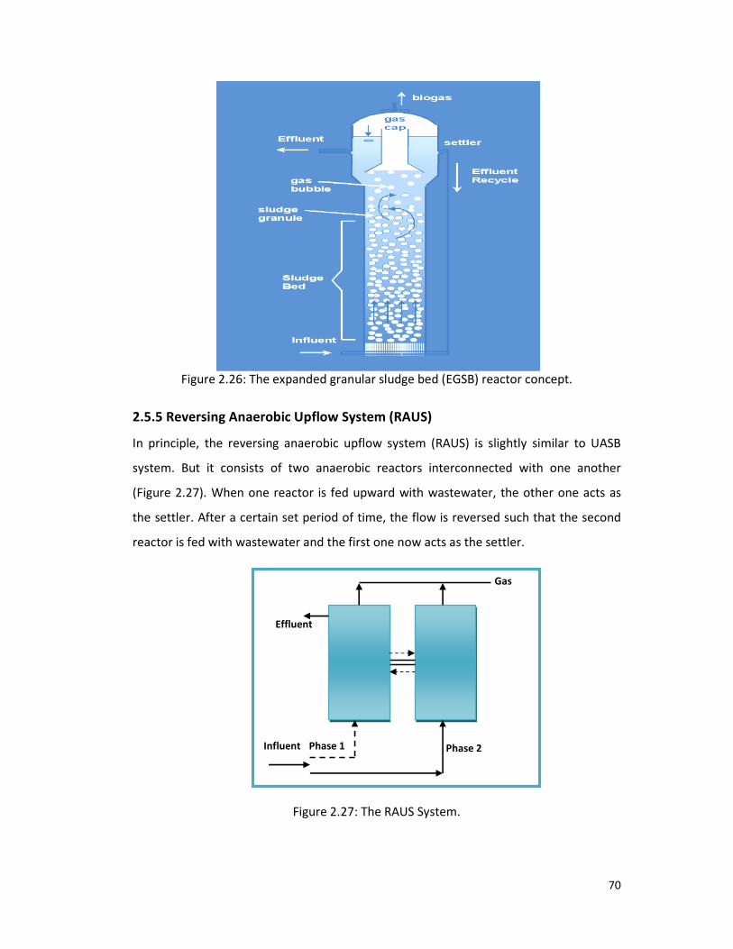
Figure 2.26: The expanded granular sludge bed (EGSB) reactor concept
2.5.5 Reversing Anaerobic Upflow System (RAUS)
In principle, the reversing anaerobic upflow system (RAUS) is slightly similar to UASB
system. But it consists of two anaerobic reactors interconnected with one another
(Figure 2.27). When one reactor is fed upward with wastewater, the other one acts as
the settler. After a certain set period of time, the flow is reversed such that the second
reactor is fed with wastewater and the first one now acts as the settler.
Effluent
Influent
The expanded granular sludge bed (EGSB) reactor concept
2.5.5 Reversing Anaerobic Upflow System (RAUS)
In principle, the reversing anaerobic upflow system (RAUS) is slightly similar to UASB
system. But it consists of two anaerobic reactors interconnected with one another
). When one reactor is fed upward with wastewater, the other one acts as
e settler. After a certain set period of time, the flow is reversed such that the second
reactor is fed with wastewater and the first one now acts as the settler.
Figure 2.27: The RAUS System.
Gas
Effluent
fluent Phase 2 Phase 1
70
The expanded granular sludge bed (EGSB) reactor concept.
In principle, the reversing anaerobic upflow system (RAUS) is slightly similar to UASB
system. But it consists of two anaerobic reactors interconnected with one another
). When one reactor is fed upward with wastewater, the other one acts as
e settler. After a certain set period of time, the flow is reversed such that the second

CHAPTER THREE
RESULTS AND DISCUSSION

71
3 Removal of Individual parameters
3.1 BOD5 removal
The removal efficiencies of various techniques used for the removal of BOD5 is described
below.
Table 3.1: Removal efficiency of BOD5
Serial
no.
Removal techniques Type of
wastewater
BOD Removal
efficiency (%)
References
01 Upflow Anaerobic Sludge Bed
(UASB) & Expanded Granular
Sludge Bed (EGSB)
N/A 97 - 99 Saleh and
Mahmood,
2003
02 Activated sludge N/A 67 Yazdi et al.,
2001
03 Aerated lagoon Paper 85 Fonade et al.,
2000
04 Vertically Moving Biofilm
System (VMBS)
Synthetic
fiber
97.9 Rodgers et al.,
2004
05 Anaerobic Baffled Reactor
(ABR)
Food
processing
95 Stewart, 2004
06 Chemically Enhanced Primary
Treatment/Trickling filter
(CEPT-TF)
N/A ≥ 85 Ahmed, 2007
07 Submerged Aerated Fixed
Film Reactor (SAFF)
Textile ≥ 85 Saral et al.,
2006
08 Internal Circulation (IC)
anaerobic reactor &
Sequencing Batch Reactor
(SBR)
Swine 99.6 Deng et al.,
2006
*N/A – Not available.
01. The Installation of the upflow anaerobic sludge bed (UASB) and expanded granular
sludge bed (EGSB) for industrial wastewater treatment (anaerobic process) was
studied which has grown very rapid by over the past (15-20 years). These systems
provided highly efficient BOD removal. The BOD reduction was about 97-99% (Saleh
and Mahmood, 2003).
02. The treatment of industrial effluents by using laboratory activated sludge unit was
studied. The result obtained has indicated that the average influent 5-days BOD was
approximately 4,000 mg/l and an average reduction to 1,200 mg/l was obtained. The
percentage reduction of up to 67% was obtained (Yazdi et al., 2001).

72
03. The aerobic biological treatment of industrial wastewaters was studied by aerated
lagoons. A methodology was developed which gave the best fit between the
biological reactions and the ideal hydrodynamic behavior of the lagoon. The BOD
degradation was about 85% (Fonade et al., 2000).
04. A vertically moving biofilm system (VMBS) was developed to treat industrial
wastewater. Removal efficiency of biological oxygen demand (BOD) was up to 97.9%
(Rodgers et al., 2004).
05. Anaerobic Baffled Reactor (ABR) utilizes separate loading and unloading cells on a
continuous feed basis. This ABR design with a storage volume of over 100,000 m3
reduces the land requirement to treat the same wastewater (300 liters per minute at
average flow rates) by 50 hectares. The ABR reduces BOD by over 95% (Stewart,
2004).
06. Chemically Enhanced Primary Treatment/ Trickling Filter (CEPT-TF) system was used
for low cost treatment of industrial effluents. The results indicated that, major part
of BOD load was removed within the CEPT module. More than 85 % of BOD5
removed by the overall system is carried out in CEPT module (Ahmed, 2007).
07. An advance process Submerged Aerated Fixed Film Reactor (SAFF) was developed for
the biodegradation of textile wastewater. The BOD5 reduction was more than 85%
(Saral et al., 2006).
08. A combined system consisting of Internal Circulation (IC) anaerobic reactor and
Sequencing Batch Reactor (SBR) was used to treat swine wastewater in order to
establish a cost-efficient wastewater treatment system. The removal rate of BOD5
was 99.6%, in the IC–SBR system with total hydraulic retention time of 5–6 days
(Deng et al., 2006).
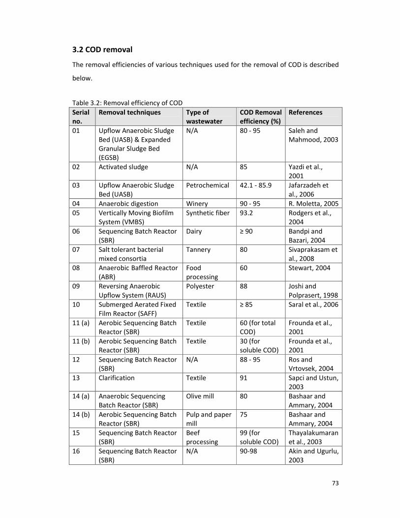
73
3.2 COD removal
The removal efficiencies of various techniques used for the removal of COD is described
below.
Table 3.2: Removal efficiency of COD
Serial
no.
Removal techniques Type of
wastewater
COD Removal
efficiency (%)
References
01 Upflow Anaerobic Sludge
Bed (UASB) & Expanded
Granular Sludge Bed
(EGSB)
N/A 80 - 95 Saleh and
Mahmood, 2003
02 Activated sludge N/A 85 Yazdi et al.,
2001
03 Upflow Anaerobic Sludge
Bed (UASB)
Petrochemical 42.1 - 85.9 Jafarzadeh et
al., 2006
04 Anaerobic digestion Winery 90 - 95 R. Moletta, 2005
05 Vertically Moving Biofilm
System (VMBS)
Synthetic fiber 93.2 Rodgers et al.,
2004
06 Sequencing Batch Reactor
(SBR)
Dairy ≥ 90 Bandpi and
Bazari, 2004
07 Salt tolerant bacterial
mixed consortia
Tannery 80 Sivaprakasam et
al., 2008
08 Anaerobic Baffled Reactor
(ABR)
Food
processing
60 Stewart, 2004
09 Reversing Anaerobic
Upflow System (RAUS)
Polyester 88 Joshi and
Polprasert, 1998
10 Submerged Aerated Fixed
Film Reactor (SAFF)
Textile ≥ 85 Saral et al., 2006
11 (a) Aerobic Sequencing Batch
Reactor (SBR)
Textile 60 (for total
COD)
Frounda et al.,
2001
11 (b) Aerobic Sequencing Batch
Reactor (SBR)
Textile 30 (for
soluble COD)
Frounda et al.,
2001
12 Sequencing Batch Reactor
(SBR)
N/A 88 - 95 Ros and
Vrtovsek, 2004
13 Clarification Textile 91 Sapci and Ustun,
2003
14 (a) Anaerobic Sequencing
Batch Reactor (SBR)
Olive mill 80 Bashaar and
Ammary, 2004
14 (b) Aerobic Sequencing Batch
Reactor (SBR)
Pulp and paper
mill
75 Bashaar and
Ammary, 2004
15 Sequencing Batch Reactor
(SBR)
Beef
processing
99 (for
soluble COD)
Thayalakumaran
et al., 2003
16 Sequencing Batch Reactor
(SBR)
N/A 90-98 Akin and Ugurlu,
2003

74
Table 3.2: Removal efficiency of COD (Continued)
Serial
no.
Removal techniques Type of
wastewater
COD Removal
efficiency (%)
References
17 Sequencing Batch Reactor
(SBR)
Synthetic 96 Uygur and Kargi,
2004
18 Continuous anaerobic
digestion (CAD)
Olive oil mill 81 Heredia and
Garcia, 2005
19 Internal Circulation (IC)
anaerobic reactor &
Sequencing Batch Reactor
(SBR)
Swine 95.5 Deng et al.,
2006
20 Sequencing Batch Reactor
(SBR)
Tannery 95 Lefebvre et al.,
2005
*N/A – Not available.
01. The Installation of the upflow anaerobic sludge bed (UASB) and expanded granular
sludge bed (EGSB) for industrial wastewater treatment was studied which has grown
very rapid by over the past (15-20 years). These systems provided highly efficient
COD removal. The UASB reactor achieved a loading rate 7.2 kg COD/m3/d HRT
(hydraulic Retention Time) 3-4 days. The best performance loading rate was 4 kg
COD/m3/d. The COD reduction was about 80-95% (Saleh and Mahmood, 2003).
02. The treatment of industrial effluents by using laboratory activated sludge unit was
studied. The amount of COD reduction was variable throughout the experiment. The
minimum reduction was about 72% and the maximum about 90%. The percentage
reduction of COD reached an average of up to 85% in effluent, a reduction from
20,000 mg/l to 3,000 mg/l (Yazdi et al., 2001).
03. The performance of an anaerobic hybrid reactor (UASB) treating petrochemical
wastewater was studied. The minimum and maximum COD reductions of the overall
reactor were 42.1 and 85.9% at influent COD concentration of 3,000 mg/l and 4,000
mg/l respectively (Jafarzadeh et al., 2006).
04. Anaerobic digestion is widely used for wastewater treatment, especially in the food
industries. With winery wastewaters (as for vinasses from distilleries) the removal
yield for anaerobic digestion was very high, up to 90–95% COD removal (R. Moletta,
2005).

75
05. A Vertically Moving Biofilm System (VMBS) was developed to treat industrial
wastewater. Removal efficiency of filtered chemical oxygen demand (COD) was up to
93.2% (Rodgers et al., 2004).
06. A bench scale aerobic Sequencing Batch Reactor (SBR) was investigated to treat the
wastewater from an industrial milk factory. The study demonstrated the capability of
aerobic SBR for COD removal from dairy industrial wastewater. The COD removal
efficiency was achieved more than 90%, whereas COD concentration varied from 400
to 2,500 mg/l (Bandpi and Bazari, 2004).
07. Tannery saline wastewater degradation studies were done as batch experiments
(incubated shaking flask) with pure monocultures of Pseudomonas aeruginosa,
Bacillus flexus, Exiguobacterium homiense and Staphylococcus aureus. The salt
concentrations were varied from 2–10% (w/v). A maximum degradation of 87.6%
was observed for P.aeruginosa. Analysis of results showed that E.homiense exhibited
a higher COD removal (90%). Salt tolerant bacterial mixed consortia showed
appreciable biodegradation at all saline concentrations (2%, 4%, 6%, 8% and 10%
w/v) with 80% COD reduction in particular at 8% salinity level, the consortia could be
used as suitable working cultures for tannery saline wastewater treatment
(Sivaprakasam et al., 2008).
08. Anaerobic Baffled Reactor (ABR) utilizes separate loading and unloading cells on a
continuous feed basis. This ABR design with a storage volume of over 100,000 m3
reduces the land requirement to treat the same wastewater (300 liters per minute at
average flow rates) by 50 hectares. The ABR reduces COD by over 60% (Stewart,
2004).
09. A new high rate anaerobic process, the reversing anaerobic upflow system (RAUS)
was used for the lowest cost wastewater treatment option for highly polluted
industrial wastewater. Results indicated that COD reduction was about 88% (Joshi
and Polprasert, 1998).
10. An advance process Submerged Aerated Fixed Film Reactor (SAFF) was developed
for the biodegradation of textile wastewater. The COD reduction was more than 85%
(Saral et al., 2006).
11. The biological treatment of a textile wastewater was investigated in an aerobic
sequencing batch reactor (SBR). The system was operated in 8-hour cycles. At

76
steady-state operation, which took 60 days to attain, the removal of total and
soluble COD was 60% and 30% respectively (Frounda et al., 2001).
12. Four different experiments in a sequencing batch reactor were carried out. In all
series COD removal was from 88 to 95% (Ros and Vrtovsek, 2004).
13. Waste pumice was chosen as an adsorbent to observe removal efficiency of COD
from textile wastewater. When the clarification of textile wastewater was
experimented by waste pumice, it had been observed that the pumice had a capacity
of adsorption. Consequently, the best COD removal efficiency was obtained by an
increase on the ratios of pumice, FeSO4 and Ca(OH)2. The combination of these
chemicals and adsorbent (e.g. 10 g pumice, 0.6 g/l FeSO4 and 0.6 g/l Ca(OH)2) was
given maximum COD removal efficiency as 91% (Sapci and Ustun, 2003).
14. Wastewaters from olive mills and pulp and paper mill industries in Jordan were
treated using laboratory scale anaerobic and aerobic sequencing batch reactors,
respectively. It was found that for anaerobic treatment of olive mills wastewater
COD:N:P ratio of about 900:5:1.7 was able to achieve more than 80% COD removal.
For extended aeration aerobic treatment of pulp and paper mill wastewater COD:N:P
ratio of about 170:5:1.5 was able to achieve more than 75% COD removal (Bashaar
and Ammary, 2004).
15. A laboratory scale sequencing batch reactor (SBR) was operated for the treatment of
a beef processing effluent from slaughtering and boning operations. An effective SBR
cycle was found for removal of COD at 22°C. Removal of biodegradable soluble COD
of greater than 99% was achieved in the SBR (Thayalakumaran et al., 2003).
16. A research was performed for the removal of COD in a laboratory scale sequencing
batch reactor (SBR) having a new operational mode. The SBR system had
simultaneous feeding and decanting conditions. High COD (90-98%) removal was
achieved by this system (Akin and Ugurlu, 2003).
17. Nutrient removal from synthetic wastewater was investigated using a four-step
sequencing batch reactor (SBR) at different 2,4 dichlorophenol (DCP) concentrations.
Adverse effects of dichlorophenol on COD removal were almost negligible for DCP
concentrations below 123 mg/L. About 96% COD removal was obtained at a DCP
concentration of 123 mg/L (Uygur and Kargi, 2004).
77
18. The purification of the olive mill wastewaters (OMW) was investigated by the
combination of an anaerobic digestion, followed by an ozonation treatment.
Continuous anaerobic digestion (CAD) was performed in a laboratory scale
bioreactor. The COD removal was 81% (Heredia and Garcia, 2005).
19. A combined system consisting of Internal Circulation (IC) anaerobic reactor and
Sequencing Batch Reactor (SBR) was used to treat swine wastewater in order to
establish a cost-efficient wastewater treatment system. Performance of post
treatment using SBR with the addition of raw wastewater was good with effluent
COD less than 300 mg/L. The removal rate of COD was 95.5%, in the IC–SBR system
with total hydraulic retention time of 5–6 days (Deng et al., 2006).
20. A study was performed to treat tannery wastewater from soak pit in a lab-scale
Sequencing Batch Reactor (SBR) for the removal of organic matter. The soak liquor
was biologically treated in an aerobic sequencing batch reactor seeded with
halophilic bacteria and the performance of the system was evaluated under different
operating conditions with changes in hydraulic retention time, organic loading rate
and salt concentration. Optimum COD removal efficiency of 95% was reached with 5
days hydraulic retention time (HRT), an organic loading rate (OLR) of 0.6 kg
COD m−3
d−1
and 34 g NaCl l−1
(Lefebvre et al., 2005).
3.3 Total Organic Carbon (TOC) removal
A research was conducted to study biological processes for treating wastewaters
containing high concentrations (e.g., 400 mg/L) of Lauryl Alkylbenzene Sulfonate (LAS).
Initial experiments were carried out using a respirometry technique and subsequently,
three different laboratory-scale bioreactor systems. The three systems studied were a
Sequencing Batch Reactor (SBR), a Sequencing Batch Biofilm Reactor (SBBR) and an
Intermittent Cycle Extension Aeration System (ICEAS). The SBR and ICEAS were operated
on a five-day cycle basis with a hydraulic retention time of four days. The SBBR was
operated mainly in a two-day cycle having a hydraulic retention time of ten days as well.
At the end of the experiment, TOC removal was 84.4%, 75.2%, 70.6%, and 46.0% for
samples initially containing 30, 60, 150, and 300 mg/L SDS (Rodezno, 2004).

78
The biological treatment of wastewater from an aminoplastic resin producing industry
was studied in a predenitrification system. The total organic carbon (TOC) values in the
feed varied from 1,423.0 to 1,599.5 mg/l, corresponding to an organic loading rate of
about 0.20 kg TOC/m3/d. High TOC removal was achieved, around 92% (Eiroa et al.,
2006).
3.4 Nitrogen (N) removal
Table 3.3: Removal efficiency of nitrogen
Serial no. Removal techniques Nitrogen
Removal
efficiency (%)
References
01 Sequencing Batch Reactor (SBR) 80-84 (TN) Ros and Vrtovsek,
2004
02 BioBalance 84.6 (TN) Vaboliene et al.,
2005
03 (a) Various yeast species 22-93 (TN) Thanh and Simard,
1973
03 (b) Various yeast species 27-90 (NH3-N) Thanh and Simard,
1973
04 Fungi 49-77 (NH3-N) Hiremath et al.,
1985
05 Sequencing Batch Reactor (SBR) 99 (NH3-N) Thayalakumaran et
al., 2003
06 Sequencing Batch Reactor (SBR) 90-95 (NH3-N) Akin and Ugurlu,
2003
07 Sequencing Batch Reactor (SBR) 46 (NH3-N) Uygur and Kargi,
2004
08 (a) Internal Circulation (IC) anaerobic
reactor and Sequencing Batch
Reactor (SBR)
99.4 (NH3-N) Deng et al., 2006
08 (b) Internal Circulation (IC) anaerobic
reactor and Sequencing Batch
Reactor (SBR)
94.3 (TN) Deng et al., 2006
09 Sequencing Batch Reactor (SBR) 96 (TKN) Lefebvre et al.,
2005
10 (a) Circulating bioreactor 90-98 (TN) Hirata et al., 2001
10 (b) Circulating bioreactor 80-92 (NH3) Hirata et al., 2001
* TN- Total Nitrogen; NH3-N-Ammonia Nitrogen; TKN-Total Kjeldahl Nitrogen
1. Four different experiments in a Sequencing Batch Reactor (SBR) were carried out.
Different COD:N:P and BOD5:N:P ratios were studied. The optimal COD:N:P was

79
100:11:2 and BOD5:N:P was 100:15:3. In all series nitrogen removal was from 80 to
84% (Ros and Vrtovsek, 2004).
2. Biological nitrogen removal was evaluated and compared by using the “BioBalance”
technology for biological nitrogen removal. Evaluating Utena Wastewater Treatment
Plant before and after the reconstruction, it was estimated that 84.6 % of total
nitrogen was removed by using the ”BioBalance” technology and total nitrogen (TN)
in the effluent was not higher than allowable norms (Vaboliene et al., 2005).
3. Treatment of wastewater by various yeast species was studied. The study screened
27 yeast strains for their ability to produce a high biomass, while maximizing
reduction of ammonia. Reported total nitrogen (TN) removal from 22 to 93%,
ammonia nitrogen (NH3-N) from 27 to 90% (Thanh and Simard, 1973).
4. Recently fungi have been recognized to perform denitrification at greater rates than
bacteria. Seven fungal species was isolated from a wastewater stabilization pond.
The study reported ammonia nitrogen (NH3-N) removal between 49 and 77%
(Hiremath et al., 1985).
5. A laboratory scale Sequencing Batch Reactor (SBR) was operated for the treatment
of a beef processing effluent from slaughtering and boning operations. An effective
SBR cycle was found for removal of nitrogen at 22°C. Removal of ammonia nitrogen
(NH3-N) of greater than 99 % was achieved in the SBR (Thayalakumaran et al., 2003).
6. A research was performed for the removal of nitrogen in a laboratory scale
Sequencing Batch Reactor (SBR) having a new operational mode. The SBR system
had simultaneous feeding and decanting conditions. High ammonia nitrogen (NH3-N)
removal of 90-95% was achieved by this system (Akin and Ugurlu, 2003).
7. Nutrient removal from synthetic wastewater was investigated using a four-step
sequencing batch reactor (SBR) at different 2,4 dichlorophenol (DCP) concentrations.
About 46% ammonia nitrogen (NH3-N) removal was obtained at a DCP concentration
of 123 mg/L (Uygur and Kargi, 2004).
8. A combined system consisting of Internal Circulation (IC) anaerobic reactor and
Sequencing Batch Reactor (SBR) was used to treat swine wastewater in order to
establish a cost-efficient wastewater treatment system. The removal rates of
ammonia nitrogen (NH3-N) and total nitrogen (TN) were 99.4% and 94.3%,

80
respectively, in the IC-SBR system with total hydraulic retention time of 5–6 days
(Deng et al., 2006).
9. A study was performed to treat tannery wastewater from soak pit in a lab-scale
Sequencing Batch Reactor (SBR) for the removal of organic matter. The soak liquor
was biologically treated in an aerobic sequencing batch reactor seeded with
halophilic bacteria and the performance of the system was evaluated under different
operating conditions with changes in hydraulic retention time, organic loading rate
and salt concentration. Optimum Total Kjeldahl Nitrogen (TKN) removal efficiency of
96% was reached with 5 days hydraulic retention time (HRT), an organic loading rate
(OLR) of 0.6 kg COD m−3
d−1
and 34 g NaCl l−1
(Lefebvre et al., 2005).
10. Biological nitrogen removal from industrial wastewater was attempted by using a
circulating bioreactor system equipped with an anaerobic packed bed and an aerobic
three-phase fluidized bed. As a result of acclimating microorganisms with change of
the hydraulic residence time, this system effectively removed nitrogen from diluted
wastewater. The removal ratio of total nitrogen (TN) was 90% to 98% and that of
ammonia (NH3) was 80% to 92% (Hirata et al., 2001).
3.5 Phosphorus (P) removal
Table 3.4: Removal efficiency of phosphorus
Serial no. Removal techniques Phosphorus
Removal
efficiency (%)
References
01 BioBalance 97 (TP) Vaboliene et al.,
2005
02 Various yeast species 100 (PO43−
) Thanh and Simard,
1973
03 Fungi 77 (PO43−
) Hiremath et al.,
1985
04 Sequencing Batch Reactor (SBR) 99 (PO43−
-P) Thayalakumaran et
al., 2003
05 Sequencing Batch Reactor (SBR) 100 (PO43−
-P) Akin and Ugurlu,
2003
06 Sequencing Batch Reactor (SBR) 22 (PO43−
-P) Uygur and Kargi,
2004
07 Sequencing Batch Reactor (SBR) 93 (PO43−
) Lefebvre et al.,
2005
* TP- Total Phosphorus; (PO43−
-P)- Phosphate Phosphorus; (PO43−
)- Phosphate.
81
1. Biological phosphorus removal was evaluated and compared by using the
“BioBalance” technology for biological phosphorus removal. Evaluating Utena
Wastewater Treatment Plant before and after the reconstruction, it was estimated
that up to 97 % of total phosphorus (TP) was removed by using the ”BioBalance”
technology and Total-P in the effluent was not higher than allowable norms
(Vaboliene et al., 2005).
2. Treatment of wastewater by various yeast species was studied. The study screened
27 yeast strains for their ability to produce a high biomass, while maximizing
reduction of phosphate. Reported phosphate (PO43−
) removal ranged from 12 to
100% (Thanh and Simard, 1973).
3. Recently fungi have been recognized to perform denitrification at greater rates than
bacteria. Seven fungal species was isolated from a wastewater stabilization pond.
The study reported phosphate (PO43−
) removal from 34 to 77% (Hiremath et al.,
1985).
4. A laboratory scale sequencing batch reactor (SBR) was operated for the treatment of
a beef processing effluent from slaughtering and boning operations. An effective SBR
cycle was found for removal of phosphorus at 22°C. Removal of phosphate
phosphorus (PO43−
-P) of greater than 99 % was achieved in the SBR (Thayalakumaran
et al., 2003).
5. A research was performed for the removal of phosphorus in a laboratory scale
sequencing batch reactor (SBR) having a new operational mode. The SBR system had
simultaneous feeding and decanting conditions. High phosphate phosphorus (PO43−
-
P) removal of 77-100% was achieved by this system (Akin and Ugurlu, 2003).
6. Nutrient removal from synthetic wastewater was investigated using a four-step
sequencing batch reactor (SBR) at different 2,4 dichlorophenol (DCP) concentrations.
About 22% phosphate phosphorus (PO43−
-P) removal was obtained at a DCP
concentration of 123 mg/L (Uygur and Kargi, 2004).
7. A study was performed to treat tannery wastewater from soak pit in a lab-scale
Sequencing Batch Reactor (SBR) for the removal of organic matter. The soak liquor
was biologically treated in an aerobic sequencing batch reactor seeded with
halophilic bacteria and the performance of the system was evaluated under different
operating conditions with changes in hydraulic retention time, organic loading rate
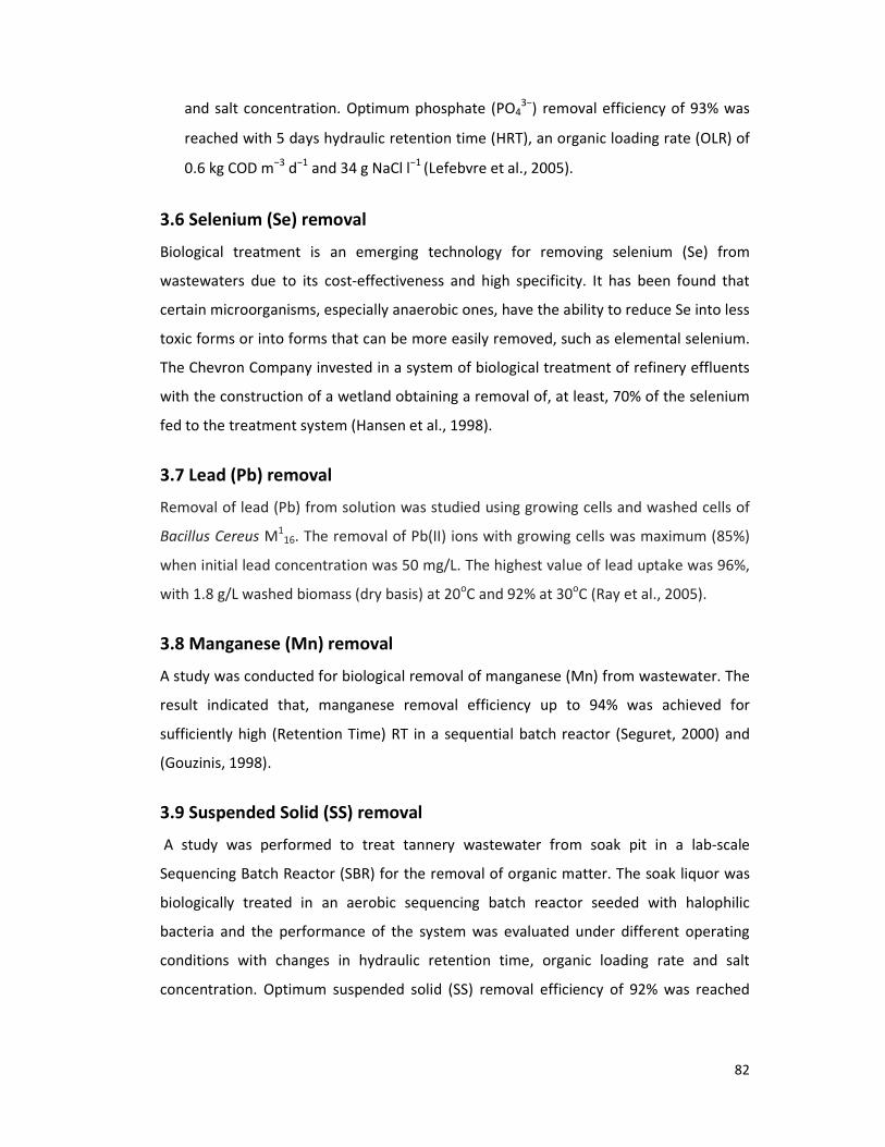
82
and salt concentration. Optimum phosphate (PO43−
) removal efficiency of 93% was
reached with 5 days hydraulic retention time (HRT), an organic loading rate (OLR) of
0.6 kg COD m−3
d−1
and 34 g NaCl l−1
(Lefebvre et al., 2005).
3.6 Selenium (Se) removal
Biological treatment is an emerging technology for removing selenium (Se) from
wastewaters due to its cost-effectiveness and high specificity. It has been found that
certain microorganisms, especially anaerobic ones, have the ability to reduce Se into less
toxic forms or into forms that can be more easily removed, such as elemental selenium.
The Chevron Company invested in a system of biological treatment of refinery effluents
with the construction of a wetland obtaining a removal of, at least, 70% of the selenium
fed to the treatment system (Hansen et al., 1998).
3.7 Lead (Pb) removal
Removal of lead (Pb) from solution was studied using growing cells and washed cells of
Bacillus Cereus M1
16. The removal of Pb(II) ions with growing cells was maximum (85%)
when initial lead concentration was 50 mg/L. The highest value of lead uptake was 96%,
with 1.8 g/L washed biomass (dry basis) at 20oC and 92% at 30
oC (Ray et al., 2005).
3.8 Manganese (Mn) removal
A study was conducted for biological removal of manganese (Mn) from wastewater. The
result indicated that, manganese removal efficiency up to 94% was achieved for
sufficiently high (Retention Time) RT in a sequential batch reactor (Seguret, 2000) and
(Gouzinis, 1998).
3.9 Suspended Solid (SS) removal
A study was performed to treat tannery wastewater from soak pit in a lab-scale
Sequencing Batch Reactor (SBR) for the removal of organic matter. The soak liquor was
biologically treated in an aerobic sequencing batch reactor seeded with halophilic
bacteria and the performance of the system was evaluated under different operating
conditions with changes in hydraulic retention time, organic loading rate and salt
concentration. Optimum suspended solid (SS) removal efficiency of 92% was reached

83
with 5 days hydraulic retention time (HRT), an organic loading rate (OLR) of 0.6 kg
COD m−3
d−1
and 34 g NaCl l−1
(Lefebvre et al., 2005).
3.10 Odor removal
Biological treatment of odor at wastewater treatment plants was studied using biofilters
and biotrickling filters for the treatment of complex air streams containing multiple
pollutants. Both the biofilter and biotrickling filter consistently removed Hydrogen
Sulfide (H2S) at greater than 97 % efficiency. Volatile Organic Carbon (VOC) removal in
the biotrickling filter was dependent on the pH (1.5-2). 35 to 45% removal was observed
for easily biodegradable VOCs such as toluene and benzene when a neutral pH was
maintained in the biotrickling filter. The results demonstrated that some organic sulfur
compounds were removed, in particular by the biofilter, but others not. Analyses of inlet
and outlet streams revealed that the odor reduction was greater than 97% in both pilot
units (Cox et al.).
A single-chamber microbial fuel cell (MFC) was used to reduce 10 chemicals associated
with odors by 99.76% (from 422 ± 23 µg/ml) and three volatile organic acids (acetate,
butyrate and propionate) by >99% (Kim et al., 2008).
3.11 Color removal
Synthetic textile wastewater and real wastewater from batik dyeing process were
decolorized by immobilized white-rot fungus Coriolus versicolor RC3 in repeated-batch
system. It was found that three cycles of repeated-batch decolorization were obtained
with more than 90% decolorization in 24 hours when a half of wastewater was removed
and replaced with new fresh dye. The immobilized fungal cell decolorized up to 80% was
reduced (Srikanlayanuku et al., 2006).
Waste pumice was chosen as an adsorbent to observe removal efficiency of color from
textile wastewater. When the clarification of textile wastewater was experimented by
waste pumice, it had been observed that the pumice had a capacity of adsorption.
Consequently, the best color removal efficiency was obtained by an increase on the
ratios of pumice, FeSO4 and Ca(OH)2. The combination of these chemicals and adsorbent
(e.g. 10g pumice, 0.6 g/l FeSO4 and 0.6 g/l Ca(OH)2) was given maximum color removal
efficiency as 87 % (Sapci and Ustun, 2003).

CHAPTER FOUR
CONCLUSION

The treatment technologies of the various industrial wastewaters were reviewed by
collecting data of the various treatment methods used for treatment of industrial
wastewater.
In this study, the parameters used for the treatment of industrial wastewater such as
biochemical oxygen demand (
carbon (TOC), nitrogen (N),
suspended solid (SS), odor,
efficiencies of particular parameters are given below.
For BOD5 removal, the efficiency of various techniques
anaerobic sludge bed (UASB) &
sludge – 67%, aerated lagoon
anaerobic baffled reactor (ABR)
filter (CEPT-TF) – 85%, submerged
circulation (IC) anaerobic reactor &
Figure 4.1: BOD
For COD removal, the efficiency of various techniques used are as follows:
anaerobic sludge bed (UASB) &
sludge – 85%, upflow anaerobic
vertically moving biofilm system (VMBS)
0
10
20
30
40
50
60
70
80
90
100
The treatment technologies of the various industrial wastewaters were reviewed by
collecting data of the various treatment methods used for treatment of industrial
In this study, the parameters used for the treatment of industrial wastewater such as
emand (BOD5), chemical oxygen demand (COD),
, phosphorus (P), selenium (Se), lead (Pb), manganese (Mn),
dor, color etc were analyzed. The results for the removal
efficiencies of particular parameters are given below.
removal, the efficiency of various techniques used are as follows:
ed (UASB) & expanded granular sludge bed (EGSB) – 99%, a
erated lagoon – 85%, vertically moving biofilm system (VMBS)
eactor (ABR) – 95%, chemically enhanced primary treatment/
ubmerged aerated fixed film reactor (SAFF) – 85% and i
irculation (IC) anaerobic reactor & sequencing batch reactor (SBR) – 99.6% (figure
BOD5 removal efficiencies of various techniques.
removal, the efficiency of various techniques used are as follows:
ed (UASB) & expanded granular sludge bed (EGSB) – 95%,
naerobic sludge bed (UASB) – 85.9%, anaerobic digestion
ystem (VMBS) – 93.2%, sequencing batch reactor (SBR)
Upflow Anaerobic Sludge Bed (UASB) &
Expanded Granular Sludge Bed (EGSB)
Activated sludge
Aerated lagoon
Vertically Moving Biofilm System (VMBS)
Anaerobic Baffled Reactor (ABR)
Chemically Enhanced Primary
Treatment/Trickling filter (CEPT-
Submerged Aerated Fixed Film Reactor (SAFF)
Internal Circulation (IC) anaerobic reactor &
Sequencing Batch Reactor (SBR)
84
The treatment technologies of the various industrial wastewaters were reviewed by
collecting data of the various treatment methods used for treatment of industrial
In this study, the parameters used for the treatment of industrial wastewater such as
, total organic
anganese (Mn),
The results for the removal
used are as follows: upflow
99%, activated
ystem (VMBS) – 97.9%,
reatment/trickling
85% and internal
6% (figure 4.1).
removal, the efficiency of various techniques used are as follows: upflow
95%, activated
naerobic digestion – 95%,
eactor (SBR) – 99%,
Upflow Anaerobic Sludge Bed (UASB) &
Expanded Granular Sludge Bed (EGSB)
Vertically Moving Biofilm System (VMBS)
Anaerobic Baffled Reactor (ABR)
-TF)
Submerged Aerated Fixed Film Reactor (SAFF)
Internal Circulation (IC) anaerobic reactor &
Sequencing Batch Reactor (SBR)
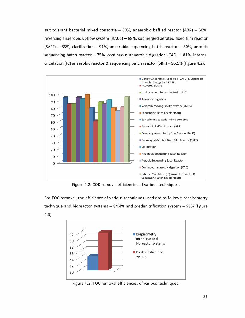
salt tolerant bacterial mixed consortia
reversing anaerobic upflow s
(SAFF) – 85%, clarification –
sequencing batch reactor –
circulation (IC) anaerobic reactor &
Figure 4.2: COD
For TOC removal, the efficiency of various techniques used are as follows:
technique and bioreactor systems
4.3).
Figure 4.3: TOC removal efficiencies of various techniques.
0
10
20
30
40
50
60
70
80
90
100
80
82
84
86
88
90
92
alt tolerant bacterial mixed consortia – 80%, anaerobic baffled reactor (ABR)
system (RAUS) – 88%, submerged aerated fixed
– 91%, anaerobic sequencing batch reactor –
75%, continuous anaerobic digestion (CAD) –
irculation (IC) anaerobic reactor & sequencing batch reactor (SBR) – 95.5% (figure
OD removal efficiencies of various techniques.
For TOC removal, the efficiency of various techniques used are as follows:
bioreactor systems – 84.4% and predenitrification system –
TOC removal efficiencies of various techniques.
Upflow Anaerobic Sludge Bed (UASB) & Expanded
Granular Sludge Bed (EGSB)Activated sludge
Upflow Anaerobic Sludge Bed (UASB)
Anaerobic digestion
Vertically Moving Biofilm System (VMBS)
Sequencing Batch Reactor (SBR)
Salt tolerant bacterial mixed consortia
Anaerobic Baffled Reactor (ABR)
Reversing Anaerobic Upflow System (RAUS)
Submerged Aerated Fixed Film Reactor (SAFF)
Clarification
Anaerobic Sequencing Batch Reactor
Aerobic Sequencing Batch Reactor
Continuous anaerobic digestion (CAD)
Internal Circulation (IC) anaerobic reactor &
Sequencing Batch Reactor (SBR)
Respirometry
technique and
bioreactor systems
Predenitrifica-tion
system
85
eactor (ABR) – 60%,
ixed film reactor
80%, aerobic
81%, internal
95.5% (figure 4.2).
For TOC removal, the efficiency of various techniques used are as follows: respirometry
– 92% (figure
Upflow Anaerobic Sludge Bed (UASB) & Expanded
Upflow Anaerobic Sludge Bed (UASB)
Vertically Moving Biofilm System (VMBS)
Salt tolerant bacterial mixed consortia
Reversing Anaerobic Upflow System (RAUS)
Submerged Aerated Fixed Film Reactor (SAFF)
Anaerobic Sequencing Batch Reactor
Aerobic Sequencing Batch Reactor
Continuous anaerobic digestion (CAD)
Internal Circulation (IC) anaerobic reactor &
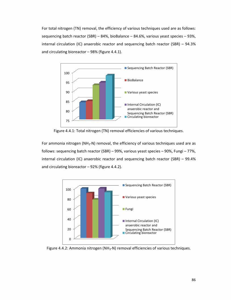
For total nitrogen (TN) removal, the efficiency of various techniques used are as follows:
sequencing batch reactor (SBR)
internal circulation (IC) anae
and circulating bioreactor – 98% (
Figure 4.4.1: Total nitrogen
For ammonia nitrogen (NH3-
follows: sequencing batch reactor (SBR)
internal circulation (IC) anaerobic reactor and
and circulating bioreactor – 92% (figure
Figure 4.4.2: Ammonia nitrogen
75
80
85
90
95
100
0
20
40
60
80
100
removal, the efficiency of various techniques used are as follows:
eactor (SBR) – 84%, bioBalance – 84.6%, various yeast species
irculation (IC) anaerobic reactor and sequencing batch reactor (SBR)
98% (figure 4.4.1).
nitrogen (TN) removal efficiencies of various techniques.
-N) removal, the efficiency of various techniques used are as
eactor (SBR) – 99%, various yeast species – 90%,
irculation (IC) anaerobic reactor and sequencing batch reactor (SBR)
92% (figure 4.4.2).
mmonia nitrogen (NH3-N) removal efficiencies of various techniques.
Sequencing Batch Reactor (SBR)
BioBalance
Various yeast species
Internal Circulation (IC)
anaerobic reactor and
Sequencing Batch Reactor (SBR)Circulating bioreactor
Sequencing Batch Reactor (SBR)
Various yeast species
Fungi
Internal Circulation (IC)
anaerobic reactor and
Sequencing Batch Reactor (SBR)Circulating bioreactor
86
removal, the efficiency of various techniques used are as follows:
arious yeast species – 93%,
eactor (SBR) – 94.3%
removal efficiencies of various techniques.
removal, the efficiency of various techniques used are as
90%, Fungi – 77%,
eactor (SBR) – 99.4%
removal efficiencies of various techniques.
Sequencing Batch Reactor (SBR)
Sequencing Batch Reactor (SBR)

For phosphorus removal, the efficiency of various techniques used are as follows:
bioBalance – 97%, various yeast species
reactor (SBR) – 100% (figure
Figure 4.5: Phosphorus
For selenium (Se) removal, the efficiency of a
lead (Pb) removal, the efficiency of c
(Mn) removal, the efficiency of s
Figure 4.6: Removal efficiencies of various techniques used for the removal of
(Se
For suspended solid (SS) removal, the efficiency of s
92%. For odor removal, the efficiency of
color removal, the efficiency of
90% (figure 4.7).
0
20
40
60
80
100
0
20
40
60
80
100
removal, the efficiency of various techniques used are as follows:
arious yeast species – 100%, fungi – 77% and sequencing
100% (figure 4.5).
hosphorus removal efficiencies of various techniques.
removal, the efficiency of anaerobic microorganisms was 70%. For
removal, the efficiency of cells of Bacillus Cereus M1
16 was 96%. For m
removal, the efficiency of sequencing batch reactor (SBR) was 94% (figure
emoval efficiencies of various techniques used for the removal of
(Se), lead (Pb) and manganese (Mn).
removal, the efficiency of sequencing batch reactor (SBR
removal, the efficiency of biofilter and biotrickling filter was 9
removal, the efficiency of immobilized white-rot fungus Coriolus versicolor
BioBalance
Various yeast species
Fungi
Sequencing Batch Reactor
(SBR)
Selenium (Se)
Lead (Pb)
Manganese (Mn)
87
removal, the efficiency of various techniques used are as follows:
equencing batch
removal efficiencies of various techniques.
was 70%. For
was 96%. For manganese
) was 94% (figure 4.6).
emoval efficiencies of various techniques used for the removal of selenium
eactor (SBR) was
was 99.76%. For
Coriolus versicolor RC3 was

Figure 4.7: Removal efficiencies of various techniques used for the removal of
suspended solid (SS), odor and color.
Finally it is found that, internal circulation (IC) anaerobic reactor & sequencing batch
reactor (SBR) are efficient techniques
is efficient technique for COD
for TOC removal, circulating bioreactor
removal and internal circulation (IC) anaerobic reactor
are efficient techniques for
and sequencing batch reactor (SBR)
In Bangladesh, a large amount of untreated industrial wastewater is releasing into
surrounding areas of the industrial areas daily. This type of wast
environmental pollution locally as well as the whole country.
effective techniques found from the review work
should be used for the treatment of industrial wastewater in Bangladesh
industrial pollution.
85
90
95
100
emoval efficiencies of various techniques used for the removal of
suspended solid (SS), odor and color.
Finally it is found that, internal circulation (IC) anaerobic reactor & sequencing batch
techniques for BOD5 removal, sequencing batch
OD removal, predenitrification system is efficient
irculating bioreactor is efficient technique for total nitrogen
irculation (IC) anaerobic reactor & sequencing batch
for ammonia nitrogen (NH3-N) removal, various yeast species
eactor (SBR) are efficient techniques for phosphorus
In Bangladesh, a large amount of untreated industrial wastewater is releasing into
surrounding areas of the industrial areas daily. This type of wastewater is causing
environmental pollution locally as well as the whole country. So, the efficient
found from the review work have higher removal efficiency
be used for the treatment of industrial wastewater in Bangladesh
Suspended solid (SS)
Odor
Color
88
emoval efficiencies of various techniques used for the removal of
Finally it is found that, internal circulation (IC) anaerobic reactor & sequencing batch
atch reactor (SBR)
is efficient technique
nitrogen (TN)
atch reactor (SBR)
arious yeast species
phosphorus removal.
In Bangladesh, a large amount of untreated industrial wastewater is releasing into
ewater is causing
efficient and cost-
have higher removal efficiency and
be used for the treatment of industrial wastewater in Bangladesh to control

CHAPTER FIVE
REFERENCES

89
AEPA (Australian Environmental Protection Authority) (1998) Environmental Guidelines
for the Textile dyeing and Finishing Industry, State Government of Victoria,
Melbourne, Victoria, Australia.
Ahmed, S. A. R. (2007) Fast-track evaluation of a compact chemically enhanced-trickling
filter system. Brazilian Journal of Chemical Engineering. vol.24 no.2.
Ajmal, M., Ahmad, A., Nomani, A. A., (1982) Microbial uptake of cadmium and its
effects on the biochemical oxygen demand. Water Research, vol. 16, pp. 1611–1614.
Ajmal, M., Ahmad, A. and Nomani, A. A. (1983) Influence of toxic metals on the
repression of carbonaceous oxygen demand. Water Research, vol. 17, pp. 799–802.
Akin B.S. and Ugurlu A. (2003) Biological removal of carbon, nitrogen and phosphorus in
a sequencing batch reactor. J Environ Sci Health A Tox Hazard Subst Environ Eng,
38(8):1479-88.
Al-Rekabi, W. S., Qiang, H. & Qiang, W. W. (2007) Improvements in Wastewater
Treatment Technology. Pakistan Journal of Nutrition, Vol. 6 (2), pp. 104-110.
Ammary, B. Y. (2004) Nutrients requirements in biological industrial wastewater
treatment. African Journal of Biotechnology, Vol. 3 (4), pp. 236-238,
[Available online at http://www.academicjournals.org/AJB]
Balaji, V., Datta, S. & Bhattacharjee, C. (2005) Evaluation on Biological Treatment for
Industrial Wastewater. IE (I) Journal—CH, Vol. 85, pp. 39-46.
Bandpi, A. M. and Bazari, H. (2004) Biological Treatment of Dairy Wastewater by
Sequencing Batch Reactor. Iranian J Env Health Sci Eng, Vol.1, No.2, pp.65-69.
Bashaar Y. and Ammary (2004) Nutrients requirements in biological industrial
wastewater treatment. African Journal of Biotechnology, Vol. 3, No. 4, pp. 236-238
[Available online at http://www.academicjournals.org/AJB/ ]

90
Benavides L. (1992), Expert Group meeting on Local Cottage Industries of Hazardous
Wastes from Small-scale and Cottage Industries, An Overview.
Braam, F., Klapwijk, A., (1981) Effect of copper on nitrification in activated sludge.
Water Research, vol. 5, pp. 1093–1098.
Chadwick M. T. and Clemett, A. E. V. (2002) Managing Pollution from Small and Medium
Scale Industries in Bangladesh: Project Proposal. Stockholm Environment Institute,
York, UK.
Chipasa K. B. (2003) Accumulation and fate of selected heavy metals in a biological
wastewater treatment system. Science Direct, Waste Management, Vol. 23, pp. 135–
143. [Available online at www.elsevier.com/locate/wasman]
Cooper, P. F. Historical aspects of wastewater treatment. Lens, P. Zeeman, G. and
Lettinga, G., editors. Decentralised Sanitation and Reuse: Concepts, Systems and
Implementation. IWA Publishing. ISBN: 1 900222 47 7.
Deng, L. W., Zheng, P. and Chen, Z. A. (2006) Anaerobic digestion and post-treatment of
swine wastewater using IC–SBR process with bypass of raw wastewater. Science
Direct. Process Biochemistry, Volume 41, Issue 4, PP. 965-969.
Dilek, F.B., Yetis, U., (1992) Effects of heavy metals on activated sludge process.
Water Sci. Technol. 26, 801–813.
Doan, H. D., Wu, J. and Mitzakov, R. (2006) Combined electrochemical and biological
treatment of industrial wastewater using porous electrodes. Journal of Chemical
Technology & Biotechnology, Volume 81 Issue 8, Pages 1398 – 1408.
Eiroa, M., Vilar, A. Kennes, C. and Veiga, M. C. (2006) Biological treatment of industrial
wastewater containing formaldehyde and formic acid. Water SA, Vol. 32 No. 1, pp.
115-118. [Available on website http://www.wrc.org.za]

91
Environment Canada, Fact Sheet about TOWARDS BETTER MANAGEMENT OF TEXTILE
MILL EFFLUENTS. Authority of the Minister of the Environment, Canada, Catalogue
No En40-641/2001. ISBN 0-662-65993-7, 2001.
EPA (1974) Wastewater Treatment Systems: Upgrading Textile Operations to Reduce
Pollution. United States Environmental Protection Agency, Washington DC, USA. In:
EPA Technology Transfer, EPA-625/3-74-004, pp. 1 – 12.
Fonade, C., Rols, J. L., Goma, G., Doubrovine, N., Bermejo, M. and Grasa, J.P. (2000)
Improvement of industrial wastewater treatment by aerated lagoon: case studies.
Water Science and Technology, Vol. 42 Nos. 5-6 pp. 193-200.
Frounda, K., Zissi, O., Kornaros, M. and Lyberatos, G. (2001) BIOLOGICAL TREATMENT OF
TEXTILE WASTE WATER IN AN AEROBIC SEQUENCING BATCH REACTOR. 7th
International Conference on Environmental Science and Technology, Ermoupolis, Syros
island, Greece. September, pp. 84-88.
Gotvajn, A. Z. and Koncan, J. Z. (2005) Combination of Fenton and Biological Oxidation
for Treatment of Heavily Polluted Fermentation Waste Broth. Acta Chim. Slov. Vol.
52, pp. 131–137.
Hamer, G., Egli, T. & Mechsner, K. (1985) Biological treatment of industrial wastewater: a
microbiological basis for process performance. Journal of Applied Bacteriology
Symposium Supplement, pp. 127-140.
Heredia, J. B. and Garcia, J. (2005) Process Integration: Continuous Anaerobic Digestion-
Ozonation Treatment of Olive Mill Wastewater. Ind. Eng. Chem. Res., 44 (23), 8750 –
8755.
Hirata, A., Nakamura, Y. and Tsuneda, S. (2001) Biological nitrogen removal from
industrial wastewater discharged from metal recovery processes. Water Science &
Technology, Vol. 44, Nos. 2-3 pp. 171–180.

92
Hiremath, A.B., Nimbargi, P.M., and Jayaraj, Y.M. (1985) Domestic sewage treatment by
fungi and biomass production. Environ. Ecol. 3: 568–571.
Imai, A. and Gloyna, E. F., (1990) Effects of pH and oxidation state of chromium on the
behavior of chromium on activated sludge process. Water Research vol. 24, pp.
1143–1150.
Important facts about wastewater discharge limits and permits, (2003) King County
Industrial Waste Program. [Available online at http://dnr.metrokc.gov/wlr/indwaste]
Ireen, T. A. (2006) Water pollution in Bangladesh, The Independent, 15 August 2008
Jafarzadeh, M. T., Mehrdadi, N., Azimi, A. A. et al. (2006) Petrochemical Wastewater
treatment Using An Anaerobic Hybrid Reactor. Pakistan Journal of Biological Sciences,
9 (6) pp. 1037-1042.
Joshi, D. L. and Polprasert, C. (1998) High Rate Anaerobic Treatment of Industrial
Wastewater in Tropics. Thammasat Int. J. Sc. Tech., Vol.3, No.1.
Kadlec, R.H. and Knight, R.L. (1996) Treatment Wetlands. New York: Lewis Publishers,
Inc.
Kim, J. R., Dec, J., Bruns, M. A. and Logan, B. E. (2008) Removal of Odors from Swine
Wastewater by Using Microbial Fuel Cells. APPLIED AND ENVIRONMENTAL
MICROBIOLOGY, Vol. 74, No. 8, pp. 2540–2543.
Lebiedowski M. (2005) Biological Removal of Impurities from Textile Industry
Wastewaters: An Assessment. Fibres & Textiles in Eastern Europe, Vol. 13, No. 1 (49).
Lefebvre, O., Vasudevan, N., Torrijos, M., Thanasekaran, K. and Moletta, R. (2005)
Halophilic biological treatment of tannery soak liquor in a sequencing batch reactor.
Science Direct.Water Research Volume 39, Issue 8, Pages 1471-1480

93
Lester, J. N., Harrison, R.M., Perry, R., (1979) The balance of heavy metals through a
sewage treatment works. I. Lead, cadmium and copper. Sci. Total Environ. 12,
13–23.
Lester, J.N., Perry, R., Dadd, A.H., (1979) The influence of heavy metals in a mixed
population of sewage origin in the chemostat. Water Research, vol.13, pp. 1055–
1063.
Liu, D.H.F. and Liptak, B.G. (1999) Wastewater Treatment. Boca Raton, Florida: Lewis.
Liu and Liptak, (1992) Wastewater Treatment and Water Environment Federation (WEF)
and American Society of Civil Engineers (ASCE), Design of Municipal Wastewater
Treatment plants (Volume 1), WEF Manual of Practice No. 8 and ASCE Manual and
Report on Engineering Practice No. 76, Vermont: Book Press Inc.
Madoni, P., Davoli, D., Gorbi, G., Vescoli, L. (1996) Toxic effects of heavy metals on the
activated sludge Protozoan community. Water Research, vol. 30, pp. 135–141.
Metcalf and Eddy, I. (1991) Wastewater Engineering: Treatment Disposal and Reuse,
3rd
ed. New York: McGraw-Hill.
Metcalf and Eddy, (2003) Wastewater Engineering, Treatment and Reuse, 4th
ed. New
York: McGraw-Hill.
Moletta, R. (2005) Winery and distillery wastewater treatment by anaerobic digestion.
Water Science & Technology, Vol 51 No. 1 pp. 137–144.
Molga, E., Cherbanski, R. & Szpyrkowicz, L. (2006) Modeling of an Industrial Full Scale
Plant for Biological Treatment of Textile Wastewaters: Application of Neural
Networks, Ind. Eng. Chem. Res. Vol. 45, pp. 1039-1046.
Nies, D.H. (1999) Microbial heavy-metal resistance. Appl. Microbiol. Biotechnol. 51, 730–
750.

94
Qasim, S.R. (1999) Waste-water Treatment Plants: Planning, Design, and Operation,
2nd
ed. Lancaster, Pennsylvania: Technomic.
Raddad, K. (2005) Water treatment and water quality. Workshop on Environment
statistics, Dakar, Senegal. 28 Feb – 4 March.
Ray, L., Paul, S., Bera, D. and Chattopadhyay, P. BIOACCUMULATION OF Pb(II) FROM
AQUEOUS SOLUTIONS BY Bacillus Cereus M1
16. Journal for Hazardous Substance
Research, Volume 5, pp. 1-21.
Reed, S. C., Middlebrooks, E. J. & Crites, R.W. (1988) Natural Systems for Waste
Management and Treatment. New York: McGraw-Hill.
Rizzo, A. C. D. L., Santos, R. L. C. D. and Millioli, V. S. Biological Selenium Removal from
Oil Refinery Wastewater: A Critical Review. XIII INTERNATIONAL CONFERENCE ON
HEAVY METALS IN THE ENVIRONMENT. pp. 1-4.
Rodgers M., Zhan X. M. and Casey, A. (2004) Oxygen Transfer and Industrial Wastewater
Treatment Efficiency of a Vertically Moving Biofilm System. Springer. Water, Air, and
Soil Pollution, Volume 151, Numbers 1-4, pp. 165-178(14).
Ros, M. and Vrtovsek, J. (2004) THE STUDY OF NUTRIENT BALANCE IN SEQUENCING
BATCH REACTOR WASTEWATER TREATMENT. Acta Chim. Slov., 51, 779-785.
Sairan, F. M. and Ujang, Z. (2004) Wastewater treatment plant design advisor using
WASDA, Water and Environmental Management Series, IWA Publishing, ISBN 1 84339
Vol. 503 (7), pp. 259-266.
Saleh, M. M. A. and Mahmood, U. F. (2003) UASB/EGSB Applications For Industrial
Wastewater Treatment. Seventh International Water Technology Conference, Egypt.
1-3 April 2003, pp. 335-344.
Sanks, R.L. and Asano, T. (1976) Land Treatment and Disposal of Municipal and Industrial
Wastewater. Ann Arbor, Michigan: Ann Arbor Science.

95
Sapci, Z., and Ustun, B. (2003) THE REMOVAL OF COLOR AND COD FROM TEXTILE
WASTEWATER BY USING WASTE PUMICE. Electronic Journal of Environmental,
Agricultural and Food Chemistry, 2 (2), pp. 286-290.
Saral, A. M., Sachidhanandam, M. and Kumar, P. S. (2006) Biodegradation of Textile
Wastewater by an Advanced Activated Sludge Process. ECO Services International,
September.
Sawyer C.C. and McCarty P.L. (1978) Chemistry for Environmental Engineers, New York:
McGraw Hill, pp. 331–514.
Seguret, F. (2000) Hydrodynamic Behavior of Full Scale Trickling Filters, Wat Res. Vol. 34,
No 5, pp.1551-1558.
SEHD (1998) Bangladesh Environment: Facing 21st Century, First Edition. Society for
Environment and Human Development (SEHD) Publications, Dhaka, Bangladesh.
Sivaprakasam, S., Mahadevan, S., Sekar, S. and Rajakumar, S. (2008) Biological treatment
of tannery wastewater by using salt-tolerant bacterial strains. Microbial Cell Factories,
[Available online at http://www.microbialcellfactories.com/content/7/1/15]
Srikanlayanukul, M., Khanongnuch, C. and Lumyong, S. (2006) Decolorization of Textile
Wastewater by Immobilized Coriolus versicolor RC3 in Repeated-Batch System with
the Effect of Sugar Addition. CMU. Journal, Vol. 5(3) pp. 301-306.
Srinivasan, R. K., Babu, S. V. S. & Jaiswal, G. (2007) A Wastewater Recycling Manual for
urban areas with case studies. New Delhi: Centre for Science and Environment.
Stewart, S. W. (2004) Co-Generation Opportunities Utilizing Sugar Industry Wastewater
Through the Use of Biological Treatment Systems. Electricity Supply Industry in
Transition: Issues and Prospect for Asia, 14-16 January, pp. 43-51.
Surittanonta, S., Sherrad, J.H., 1981. Activated sludge nickel toxicity studies. J. Water
Pollut. Control Fed. 53, 1314–1322.

96
Technical and Regulatory Guidance Document for Constructed Treatment Wetlands,
Interstate Technology & Regulatory Council, December, 2003.
Thanh, N.C., and Simard, R.E. (1973) Biological treatment of wastewater by yeasts.
J.Water Pollut. Control Fed. 45: 675–680.
Thayalakumaran, N., Bhamidimarri, R. & Bickers P. O. (2003) Biological nutrient removal
from meat processing wastewater using a sequencing batch reactor. Water Sci.
Techno., 47(10):101-8.
Ucisik, A. S. and Henze, M. (2004) Biological denitrification of fertilizer wastewater at
high chloride concentration. Water SA, Vol. 30, No. 2, pp. 191-195.
[Available online at http://www.wrc.org.za]
Ullah, A. N. Z., Clemett, A., Chowdhury, N. et al. (2006) Human Health and Industrial
Pollution in Bangladesh. Bangladesh Centre for Advanced Studies, Dhaka: Genesis
(Pvt.) Ltd.
Uygur, A., Kargi, F. (2004) Biological Nutrient Removal from Synthetic Wastewater
Containing 2,4 Dichlorophenol in a Sequencing Batch Reactor. Environmental
Engineering Science, 21(5): 569-574.
Vabolicne, G., Bronislovas, A. and Matuzcvieius (2005) INVESTIGATION INTO BIOLOGICAL
NUTRIENT REMOVAL FROM WASTEWATER. Journal of Environmental Engineering
and Landscape Management, Vol XIII, No 4, pp. 177-181.
Vandevivere, P. C., Bianchi, R. & Verstraete, W. (1998) Treatment and Reuse of
Wastewater from the Textile Wet-Processing Industry: Review of Emerging
Technologies. J. Chem. Technol. Biotechnol. Vol. 72, pp. 289-302.
Volkman, S. (2003) Sustainable Wastewater Treatment and Reuse in Urban Areas of the
Developing World. M.Sc., Michigan Technological University.

97
Water Environment Federation and American Society of Civil Engineers (1992). Design of
Municipal Wastewater Treatment Plants, Volume 1. WEF Manual of Practice No. 8
and ASCE Manual and Report on Engineering Practice No. 76. Vermont: Book Press
Inc.
WASTEWATER TREATMENT TECHNOLOGIES: A GENERAL REVIEW. ECONOMIC AND
SOCIAL COMMISSION FOR WESTERN ASIA. United Nations, New York, 2003.
Wiesmann, U., Choi, I. S. & Dombrowski, E. M. (2007) FUNDAMENTALS OF BIOLOGICAL
WASTEWATER TREATMENT. Environmental Engineering and Management Journal,
Vol. 6, No. 4, pp. 329-330.
Wyszynska, M. (2006) Biological treatment continues to be the “bread and butter”
technology for the European wastewater treatment equipment market, Frost &
Sullivan Market Insight, 23 November.
Yazdi, M. K. S., Azimi, C. & Khalili, M. B. (2001) Study of the Biological Treatment of
Industrial Waste Water by the Activated Sludge Unit. Iranian J. Publ. Health, Vol. 30,
Nos. 3-4, PP. 87-90.
Web address: www.wikipedia.com