m series cutting system - gerber scientific · pdf fileelcome to the world of automated...
TRANSCRIPT

Volume
1
GERBER SCIENTIFIC PRODUCTS, INC Installation and Operation
M Series Cutting System

I N S T A L L A T I O N A N D O P E R A T I O N G U I D E
M Series Cutting System
© Gerber Scientific Products 83 Gerber Road
South Windsor, CT 06074
800-222-7446 (SIGN) pr 860-643-1515
www.gspinc.com

Copyright Notice COPYRIGHT © 2008 Gerber Scientific International, Inc. All Rights Reserved. This document may not be reproduced by any means, in whole or in part, without written permission of the copyright owner. This document is furnished to support the M Series Cutting Table. In consideration of the furnishing of the information contained in this document, the party to whom it is given assumes its custody and control and agrees to the following: 1 The information herein contained is given in confidence, and any part thereof shall not be copied or reproduced without written consent of Gerber Scientific Products. 2 This document or the contents herein under no circumstances shall be used in the manufacture or reproduction of the article shown and the delivery of this document shall not constitute any right or license to do so.
Printed in USA OMEGA and ART Path are trademarks and MVision-Cut is a registered trademark of Gerber Scientific Products, Inc. Adobe Illustrator is a registered trademark of Adobe Systems, Inc. Fantastik is a registered trademark of S.C. Johnson and Sons. X-ACTO is a registered trademark of Elmer’s Products, Inc. Coroplast is a trademark of Coroplast Inc. Alumalite is a trademark of Laminators, Inc. Dibond is a registered trademark of Alcan Composites USA.


Table of Contents
No Power................................................................................23 Site Preparation and Installation .................................................4 Manual Movement .................................................................23
Origin .....................................................................................24 Floor Plan .....................................................................................4 Vacuum...................................................................................24 Preparation ..............................................................................4 Run .........................................................................................25 External Inputs and Connections .................................................5 Pause......................................................................................25 Setup requirements...................................................................5 Go To......................................................................................26 Vacuum Blower ........................................................................5 Setup.......................................................................................27 Automatic Blower Operation...............................................5 Test Cut ..................................................................................31 Pneumatic.................................................................................6
Electrical ..................................................................................6 Frontend Software .......................................................................32 Electrical Domestic..................................................................6 Electrical Europe .....................................................................7 Opening a CAD File ..................................................................32 Network ....................................................................................7 Today’s Files..........................................................................32
Vacuum Blower............................................................................7 Open .......................................................................................33 Dimensions ...............................................................................7 Modifying a File ........................................................................33
Shipping and Handling.................................................................7 Rotate .....................................................................................33 Access .......................................................................................7 Mirror.....................................................................................33 Arrival ......................................................................................8 Scale .......................................................................................33 Labor requirements:.................................................................8 Move.......................................................................................33 Loading Dock ...........................................................................8 Step & Repeat ........................................................................34 Fork Lift....................................................................................8 Remove Common Lines..........................................................34 Uncrating .................................................................................8 Sequence Slots........................................................................34 Tools .........................................................................................8 Channel Width Expansion .....................................................35
Select Single ...........................................................................35 Machine Overview..........................................................................9 Set Color ................................................................................36
Make Group ...........................................................................36 Operational Features ....................................................................9 Select All Before.....................................................................36 Main Power Disconnect...........................................................9 Delete .....................................................................................37 Operators Panel .....................................................................10 Set Origin ...............................................................................37 Safety Beam............................................................................10 Reverse Direction...................................................................37 Hand Controller .....................................................................10 Turn Clockwise / Turn Counter-Clockwise ...........................37 File Preparation Software .....................................................10 Offset Path .............................................................................37 Frontend Software..............................................................10 End Select...............................................................................37 ART Path Software ............................................................10 Select Group...........................................................................38 Warning labels............................................................................10 Set Color ................................................................................38 Handling the warning labels..................................................11 Delete .....................................................................................38 Warning labels on front of cutter...........................................11 Drag & Drop..........................................................................38 Warning labels on side of cutter ............................................12 End Select Group ...................................................................38 Warning labels on back of cutter ...........................................12
Creating a Layout.......................................................................38 Warning labels on top of cutter .............................................13 Insert ......................................................................................38 Operation procedure labels ........................................................14 Cut ..........................................................................................39 Operational labels on front of cutter .....................................14 Copy .......................................................................................39 Operational labels on side of cutter ......................................15 Paste.......................................................................................39 Operational labels on back of cutter .....................................16 Drag & Drop..........................................................................39 Operational labels on top of cutter........................................17 Save As ...................................................................................39 Theory of Operation...................................................................18 Test Cuts.................................................................................39 Referencing the Machine .......................................................18 Laser Test Cut ........................................................................39 Laser Pointer..........................................................................18
Changing View Settings ............................................................40 Blade Calibration...................................................................18 Zoom Window ........................................................................40 Run Time Settings...................................................................19 Zoom Full Screen...................................................................40 Pausing...................................................................................19 Zoom Out................................................................................40 Automatic Tool Scanning .......................................................19 Zoom In ..................................................................................40
Hand Controller ...........................................................................20 Zoom Previous .......................................................................40 Material..................................................................................40
Navigating ..............................................................................21 Line Types ..............................................................................41 Scrolling .................................................................................21 Line Directions.......................................................................41 Selecting .................................................................................21 Points as Stars........................................................................41 Editing ....................................................................................21 Colors.....................................................................................41
Hotkeys.......................................................................................22 Changing File Options ...............................................................42 Menus .........................................................................................22 Options ...................................................................................42
Power-Up ...............................................................................22 Optimization ......................................................................42 Reference ................................................................................22 DXF Filters ........................................................................44 Main Menu .............................................................................23
i

Miscellaneous.....................................................................45 Units .......................................................................................46 Language................................................................................46
Controlling the Machine ............................................................46 Hand Controller .....................................................................46
Running a File ............................................................................47 The Job Ticket ........................................................................47
Material ..............................................................................48 Settings ...............................................................................50 Color Map ..........................................................................51 Saving Jobs.........................................................................52
Making a Crease Matrix.............................................................53 Using the Tools .............................................................................56
Tool Head ...................................................................................56 The Tools....................................................................................57
Reciprocating Knife ...............................................................57 Installing the Reciprocating Knives...................................58
Drag Knife..............................................................................59 Crease Wheel..........................................................................59 Ballpoint Pen..........................................................................59 Utility Blade Tools .................................................................59 Light Duty Pneumatic Router ................................................60
Installing the Light Duty Router tool.................................60 Vinyl Spring Knife ..................................................................62
Blade Wear.........................................................................62 Installing the Vinyl Spring Knife.......................................63 Testing the tool force .........................................................63 Replacing the Vinyl Spring Knife blade............................63
Using the MVision-Cut Laser Registration Device...................65 Theory of operation....................................................................65 Creating compatible artwork......................................................66
Creating M Series targets in OMEGA...................................66 Exporting print data from OMEGA...................................67 Saving cut data in OMEGA ...............................................68 Exporting cut data from OMEGA ....................................68
Creating M Series targets in Adobe Illustrator .....................69
Saving cut data from Adobe Illustrator .............................69 Exporting cut data from Adobe Illustrator ........................70
Testing the sensitivity of the registration sensor .......................70 Adjusting the registration sensor ...............................................71 Using the MVision-Cut laser registration device ......................73 Scanning errors ..........................................................................73 Aligning the visible pointer and registration sensor..................74
Aligning the visible pointer....................................................74 Aligning the registration sensor ............................................75
Outputting a Job ..........................................................................77 Positioning the Work Piece........................................................77 Turning on the Vacuum .............................................................78
Vacuum Pressure Gauge .......................................................78 Preparing the Data......................................................................79
Sending a job to the cutter from Gerber ART Path...............79 Installing the Tools ....................................................................79 Setting the Origin.......................................................................80 Running the File.........................................................................80
Maintenance .................................................................................81 Daily...........................................................................................81 Weekly .......................................................................................82 Monthly......................................................................................82 Yearly.........................................................................................82 Adjusting the lubricator .............................................................83
Adjusting the oil flow .............................................................83 Appendix A – Floor Plan.............................................................84
Appendix B – Shipping Crates ...................................................85
Appendix C – Part Number Reference and Tool Tree ............86
Appendix D – Vacuum Zones .....................................................97
Certificate of Installation, Training, and Acceptance.............98
ii

S I T E P R E P A R A T I O N A N D I N S T A L L A T I O N
3
Volume
1 Introduction You have purchased the finest Cutting Table on the market today. Follow along in this guide to maximize your investment.
elcome to the world of automated substrate cutting and low volume production runs. The Gerber M Series Cutting System is a versatile machine which can function as a router and contour cutter. It can easily cut flexible substrates like vinyl as well as a variety of rigid substrates.
Whether this is your first Cutting Table or you are a seasoned operator please read the following pages to learn important information about the safe operation of your new machine and to understand its many features.
W
I C O N K E Y
Safety information
Important point
Hand Controller
Frontend Software
Throughout this manual, you will see these icons to bring your attention to various points. Pay particular attention to the safety information icon.
This manual is not intended to replace operator training performed by Gerber personnel. It is to be used as a reference to reinforce the training. Please contact Gerber to schedule training for your new Cutting Table operators.
IMPORTANT SAFETY INSTRUCTIONS SAVE THESE INSTRUCTIONS

Chapter
1 S I T E P R E P A R A T I O N A N D I N S T A L L A T I O N
4
Site Preparation and Installation Preparing for the arrival of your new machine.
rior to the arrival of your machine there are certain things you can prepare to facilitate a quick and smooth installation. The following information will guide you. P
Floor Plan Refer to Appendix A – Floor Plan for the dimensions of the machine and necessary clearances.
Preparation Allow sufficient room for operator access and work handling.
Vacuum, electrical and pneumatic connections are most conveniently attached at the rear and to the left of the machine.
Clean and wax the floor if appropriate. To avoid static electricity, which can interfere with computer operations, carpets are not recommended.
Isolation of machine by partitions or windowed walls should be considered, as the machine generates noise that may be distracting to CAD personnel.

S I T E P R E P A R A T I O N A N D I N S T A L L A T I O N
5
External Inputs and Connections For international installations: The machine should be plugged into a disconnecting
box with a lockout mechanism in keeping with local and national requirements.
Setup requirements 90 PSI air at 6 SCFM (6.2 BAR at 9.5 mn
3/h), filtered to 5 microns. Minimum 3hp compressor required.
Domestic: 2 dedicated 115 Volt power outlets rated for 20 amps with no extension cables.
European: 2 dedicated 220 Volt power outlets rated for 10 amps with no extension cables.
3 phase 35 AMP power for blower
Motor starter for blower (manual or magnetic starter)
Vacuum Blower Prior to delivery of your machine, the vacuum blower should be shipped to you. The blower must be installed as close to the machine as is practical.
The blower is to be mounted on the supplied rubber shock mounts. Do not lag bolt directly to a floor as this can distort the blower housing. The blower may be mounted vertically or horizontally on a wall, or suspended from a roof. The maximum allowable ambient temperature is 100 degrees F (38° C). The blower has a high airflow and produces considerable heat and noise, even with the supplied muffler.
Four-inch PVC piping must be run between the vacuum blower to within six feet of the rear of the Cutting Table. Try to minimize the use of 90-degree elbows to minimize flow losses. Reduce to a 2 ½" NPT female thread at each end. Gerber supplies 2 ½" NPT barbed fittings and flexible hose to connect the blower and machine to the 4" PVC.
The motor starter is customer-supplied and must be wired in conformance with local electrical codes. The start/stop switch should be mounted near to the front left of the Cutting Table.
Contact customer service to be sure the vacuum pump is shipped early.
Automatic Blower Operation Note that if you would like to use a magnetic starter as opposed to a manual starter, provision is made inside the Gerber controller to pilot the starter. We provide a

S I T E P R E P A R A T I O N A N D I N S T A L L A T I O N
6
normally open set of relay contacts and two terminals for field hookup. The vacuum blower can then be automatically controlled by the cutting system.
Pneumatic A 90 PSI at 6 SCFM (6.2 BAR at 9.5 mn
3/h) pneumatic supply is required for the machine. The air quality should be clean, dry, and filtered to 5 microns. A male & female quick disconnect fitting is supplied with the machine. The barb fitting is for 5/16" ID hose. The connection on the Cutting Table is in the left rear of the base.
Piping runs over 50 feet long should use ¾" or larger piping. A drip leg and coalescing filter should provide sufficient quality. Dryers may be required on pneumatic systems that produce more water than a coalescing filter can accommodate.
If your existing air system lacks sufficient capacity, a compressor will be required. The minimum acceptable size is 3 HP. You will have to provide filtration and possibly a drier to meet the above air quality requirements.
Electrical Table 1 shows the electrical requirements for the 10 HP vacuum blower.
10 HP Vacuum Blower Electrical Requirements 60 Hz 10/7.5 HP/kW 50 Hz 8/6 60 Hz 208-230/460-3 Voltage 50 Hz 190-220/380-440-3 60 Hz 35-29.5/15 Amps 50 Hz 27-23/13.5-12.3 60 Hz 120 @ 460V Starting Amps 50 Hz 143 @ 380V
Insulation Class F Recommended NEMA Starter Size 2/1 Net Weight (lbs/kg) 293/133
Table 1 Electrical Domestic Customer must provide service per local code. The machine requires a dedicated 20 AMP circuit at 115V/60 Hz. An equivalent 50 Hz. power source may be used if the factory is notified at the time of order.
Note that on a nominal 115V USA installation, the line voltage must be in the range of 110V to 122V for proper operation of the machine. The service outlet should be within four feet of the left rear of the machine. The machine must not be run through an extension cord.
The second 20 AMP circuit at 115V/60 Hz is required for the shop vacuum (chip collector).

S I T E P R E P A R A T I O N A N D I N S T A L L A T I O N
7
Electrical Europe Customer must provide service per local code. The machine should be plugged into a disconnecting box with a lockout mechanism in keeping with local and national requirements. The machine requires a dedicated 10 AMP circuit at 220V/50 Hz.
The second 10 AMP circuit at 220V/50 Hz is required for the shop vacuum (chip collector).
Network A network cable is desirable for connection between the Cutting Table and the CAD computer. If no network exists or if no connection is setup, a disk must be used to transfer substrate files from the CAD computer to the Cutting Table.
Vacuum Blower Dimensions Figure 1 shows the dimensions of the vacuum blower supplied with your Cutting Table.
Figure 1 - 10 HP Vacuum Blower
Shipping and Handling Access During installation, large machine parts will need to be moved into final position. Any large objects in the work area should be moved out of the way prior to installation.

S I T E P R E P A R A T I O N A N D I N S T A L L A T I O N
8
Arrival Refer to Appendix B – Shipping Crates for the dimensions of the shipping crates.
The M1200 is shipped fully assembled. Refer to Appendix A – Floor Plan to determine if the machine will fit through any doors or elevators to get to the final location. If the machine will not fit then it will need to be disassembled and moved in pieces. The service technician will require help during this process.
With any other machine except the M1200, four persons can handle the major assemblies, all of which break down into sub-assemblies weighing 250 or less.
Note that the vacuum pump skid is usually shipped prior to the cutting table.
Labor requirements: Two people, each capable of lifting 50 lbs. (23 kg) must be available to assist the technician on the first day of installation. It is the customer's responsibility to ensure that these people are on hand. If on-site staff is not available, contact local temporary agencies or moving companies to hire them.
Loading Dock The availability of a loading dock will determine what type of truck is used. Please inform Gerber of this in advance of installation.
Fork Lift A forklift is desirable but not necessary. A pallet and hand-operated jack and dollies are necessary.
Uncrating Wait for Gerber Service personnel before uncrating.
Tools When installing the machine, Gerber Service personnel will need access to the following:
1. Claw hammer
2. Pry bar
3. 3/8" reversible/variable speed pistol drill
4. Extension cord
5. Fantastik® or another general purpose cleaner
6. Cloth rags
7. Spray can of 10-weight oil
8. Vacuum cleaner

M A C H I N E O V E R V I E W
9
Machine Overview
Chapter
2 Information on safety and control locations.
he M Series is controlled via a combination of devices. These are the operator’s panel, safety beam, hand controller, and Frontend software. Pay particular attention to the safety information. T
IMPORTANT SAFETY INSTRUCTIONS SAVE THESE INSTRUCTIONS
DANGER The M Series table is a computer numerically controlled machine. It can move
abruptly without warning due to any number of hardware or software failures. It is never safe to reach into the working area of the machine or access the tools unless the red stop button is depressed. Under no circumstances should any person reach under or over the safety beams unless the red stop button is depressed.
Operational Features Main Power Disconnect The main power disconnect is located on the left side of the electric enclosure. This electric enclosure is mounted to the left side of the base of the Cutting Table.
At the end of each working day, this switch should be turned off to increase the life of the internal components and to save energy.
This disconnect must be turned off before opening the electrical cabinet for any reason.

M A C H I N E O V E R V I E W
10
Operators Panel The operator’s panel is the location of two important buttons (located at front left-hand side of machine).
Emergency Stop Button (Red). Push to turn off machine for emergency or when not in use, or to access the tools. Twist and pull to enable the power on button.
Power On Button (Green). Push to turn on machine (will light up).
For power to turn on, the main power disconnect must be on, the Emergency Stop Button must be pulled out, the safety beams must be clear, and the machine must not be outside its working area.
Safety Beam The photoelectric beam is a safety feature designed to stop all machine motion, in an
emergency or otherwise. Interrupting the beam stops the machine. To restart, press the Power On Button (green). In the event that the beam is interrupted while running a file, the file can be continued using the Hand Controller or the Frontend Software.
The power on button will not work if the beam is not clear.
Hand Controller The hand controller is used for manual operation of the machine and convenient access to tool settings. See Chapter 3.
File Preparation Software There are two software options for preparing file data for the Cutting Table: Frontend Software or Gerber ART Path software
Frontend Software This software resides on its own computer inside the stand-alone computer cart. This software imports substrate files from your CAD system and prepares the data for the Cutting Table. See Chapter 4.
ART Path Software Gerber ART Path Software resides on its own computer inside the stand-alone computer cart. ART Path can import many industry standard file types including but not limited to DXF, AI, CDR, EPS, and Gerber Plot (PLT) files and prepare them for the Cutting Table. See “Preparing the data” on page 79 and the ART Path help system for complete instructions.
Warning labels The handling, locations, and types of warning labels are described in the following sections. Warning labels are attached to areas of the cutting table which require

M A C H I N E O V E R V I E W
11
attention. Read and understand their positions and contents thoroughly before using the M Series cutting table.
Handling the warning labels Make sure that all labels can be recognized. If text or illustrations cannot be seen clearly, either clean or replace the label. When cleaning labels, use a cloth with water or neutral detergent. Do not use a solvent or gasoline to clean the labels. If a warning label is damaged, lost, or cannot be recognized, replace the label. To replace a warning label, contact your Gerber distributor.
Warning labels on front of cutter
Figure 2
914672 Hand Crush Label
914373 Emergency Stop Label
923484-01 Power On Label
M A C H I N E O V E R V I E W
12
Warning labels on side of cutter
Figure 3
915243 Hand Cut/Crush Label
923350 Electrical Shock Label
Warning labels on back of cutter
Figure 4
A320545 Vacuum Voltage label
M A C H I N E O V E R V I E W
13
Warning labels on top of cutter
Figure 5
914672 Hand Crush Label
914678 Body Crush Force Label
915244 Cutting Fingers/Hand Label

M A C H I N E O V E R V I E W
14
Operation procedure labels The operation, maintenance, and machine identification labels are described in this section. Read and understand the locations and contents of these labels thoroughly before performing your work.
Operational labels on front of cutter
Figure 6
914373 E-Stop Label
923484-01 Power-on Label

M A C H I N E O V E R V I E W
15
Operational labels on side of cutter
Figure 7
A914735 Machine Identification Label
A320544 Power Control Label

M A C H I N E O V E R V I E W
16
Operational labels on back of cutter
Figure 8
A301018-00 Filter/Regulator Label
A301018-02 Lubrication Label
M A C H I N E O V E R V I E W
17
Operational labels on top of cutter
Figure 9
A320406-00 Vacuum Zone Label

M A C H I N E O V E R V I E W
18
Theory of Operation Your Cutting Table is a self-contained computer numerically controlled machine. With the notable exception of the power control and safety beam, it is operated solely through the Hand Controller. This is by design so that there is a single point of operation for the machine. Hot keys to minimize operator keystrokes access the most common tasks you will perform with it. Some common tasks include:
• Referencing the machine after power is turned on.
• Moving the tools to various locations on the machine.
• Setting an origin for the job you are about to run.
• Verifying the extents of the job you are about to run.
• Entering blade length calibration values for a tool after a blade change.
The following sections will explain some of the finer points of the operational characteristics of your machine. Referencing the Machine The Cutting Table uses optical incremental encoders for position feedback to the motion controller. Because they are incremental, there is no way to relate the current
encoder count to a location on the machine when the power is first applied. In order to establish this relationship, the machine must be referenced before it can be used. See Chapter 3 for help in using the Hand Controller to initiate
the reference sequence. The reference sequence drives all of the axes to known physical locations on the machine and then sets all the encoder counts to zero.
Referencing is required before the machine is operational.
Laser Pointer Your machine is equipped with a red LED type pointer. It is between tools 1 and 2 in the tool head. This pointer is used to give a visual indication of the current origin and extents of the substrate file in the controller. When these menu items are selected, the machine will move the laser pointer to the corresponding locations on the surface.
Blade Calibration In order to know how far to lower the tool head to cut to a certain depth, the physical relationships of the surface, tool holder stroke, tool, and Z-axis reference position are all carefully measured at the factory and entered into a configuration file inside the machine controller. The one variable that cannot be hard coded is the amount the knife blade protrudes from the blade holder. This is because the blade holders are used to cut a wide variety of materials and thickness. Therefore, it is important that whenever you install a blade into a holder, you enter the new Blade Length value using the Hand Controller (see page 28). If you need a blade calibration that is not
M A C H I N E O V E R V I E W
19
defined by the blade depth gauge then you must use the supplied dial calipers to measure the blade calibration. See Chapter 5 for more information on blade calibration.
Entering an incorrect calibration or forgetting to change it after a blade change is the most common reason for cutting to an incorrect depth.
Run Time Settings Once your blade calibrations are entered into the controller, the machine is ready to run jobs. The machine is capable of activating its tools and applying various settings to the tools such as velocity, pressure and depth. The tools can be activated in any specific order and the same tool can be operated with different settings in the same job.
When using Frontend Software, all this run time behavior is determined by the settings used in the software. Think of this program as the data preprocessor. It takes your CAD output file and applies parameters for the tools based on the colors of the lines and arcs in the file. When you press the Run button in the Job Ticket, you are downloading the instructions to the machine controller.
The downloaded instructions are held in a buffer waiting for the operator to select Run from the Hand Controller.
Pausing A running job can be paused by pressing a key on the hand controller or interrupting the safety beam or pressing the red emergency stop switch. In all but the latter case, you should be able to resume at the point of the interruption. While interrupted, you can select a tool and change its settings in the hand controller. When you resume the changes will apply. Please note that these changes are only in the internal buffer and do not migrate up to the Frontend Software.
Automatic Tool Scanning One of the features of your machine is that when you start a job the tool head spins all of the tools and reads each tool’s unique identifier. This is done for two reasons. The first is so the controller knows what holder the tool is in. The second reason is to allow you to use more than three tools in a job. During operation, if a tool is required by the job and it is not in the tool head, the machine will pause and the operator will be prompted to install the missing tool.

H A N D C O N T R O L L E R
20
Hand Controller
Chapter
3 A quick and portable way to operate your machine.
he hand controller must be used to reference and configure the machine, set an origin, and run substrate files. It is the single point of control for your Cutting Table. The hand controller has a four-line display and many labeled buttons (see Figure 10).
T
Figure 10 - Display and Buttons

H A N D C O N T R O L L E R
21
Navigating The hand controller shows a series of menus, to be navigated with the following buttons:
BTTN or BTTN : Executes the selected menu item or goes into the next menu. OK MENU
BTTN or BTTN : Navigates back one menu.
BTTN or BTTN : Changes the selection, scrolling the menu if necessary.
BACK SPACE
↓ ↑
CANCEL
Scrolling The hand controller screen can show up to four lines at once. Use BTTN or BTTN to scroll.
Selecting The currently selected menu item will be highlighted with < > on either side.
The current value of a setting (where applicable) will be enclosed in [ ] brackets.
For example, in this menu:
Reference Machine is the current selection. Pressing BTTN will reference the machine.
The current setting for Units is English.
Editing When changing a number value, simply enter the new number and press BTTN when done.
If you make a mistake while editing, simply press BTTN to erase it.
If you wish to exit the menu without changing the value at all, just press BTTN .
↑
<Reference Machine> Vacuum Units [English] Exit
OK
OK
BACK SPACE
CANCEL
↓
H A N D C O N T R O L L E R
22
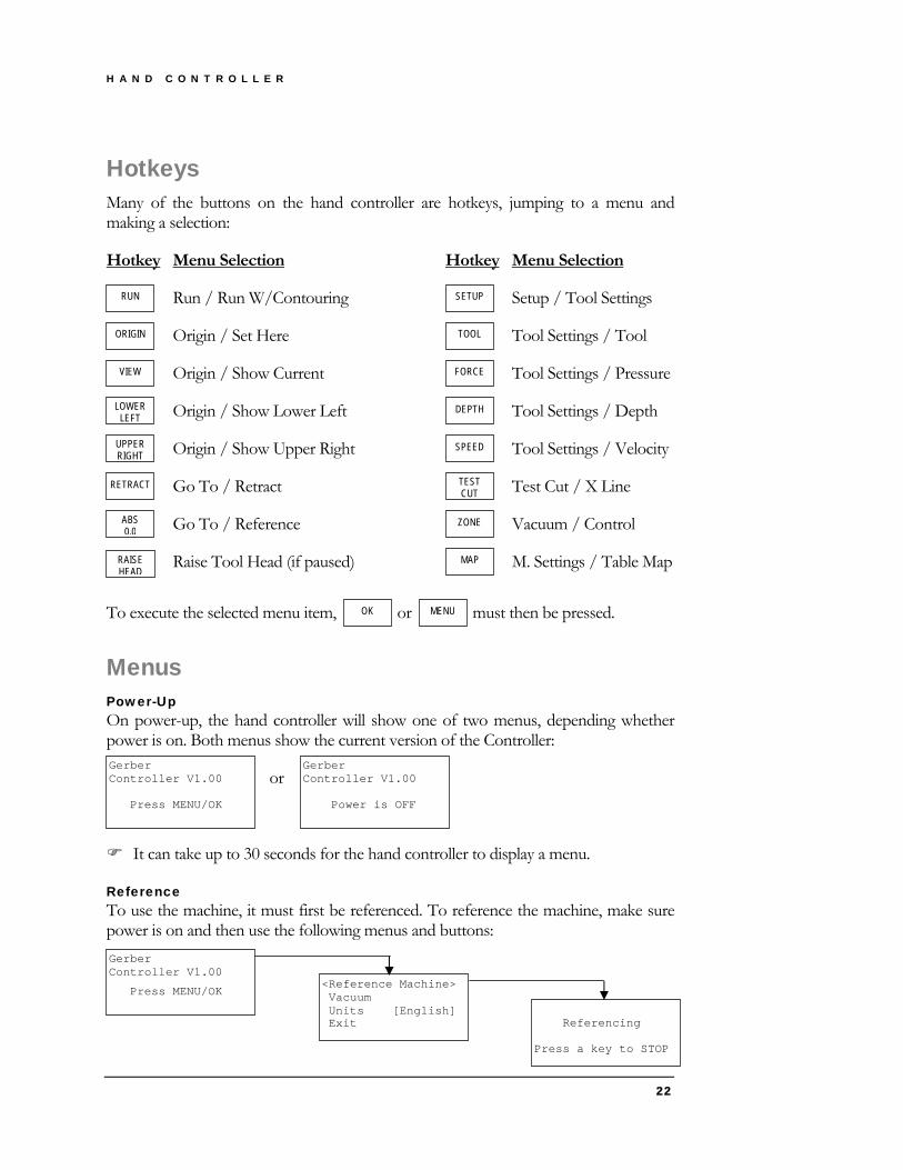
Hotkeys Many of the buttons on the hand controller are hotkeys, jumping to a menu and making a selection:
Hotkey Menu Selection Hotkey Menu Selection
Run / Run W/Contouring Setup / Tool Settings RUN SETUP
Origin / Set Here Tool Settings / Tool
<Reference Machine> Vacuum Units [English] Exit
Gerber Controller V1.00
Press MENU/OK
Referencing Press a key to STOP
Origin / Show Current Tool Settings / Pressure
Origin / Show Lower Left Tool Settings / Depth
ORIGIN
VIEW
LOWER LEFT
TOOL
Origin / Show Upper Right Tool Settings / Velocity
Go To / Retract Test Cut / X Line
Go To / Reference Vacuum / Control
FORCE
DEPTH
SPEED
TEST CUT
ZONE
UPPER RIGHT
RETRACT
ABS 0,0
Raise Tool Head (if paused) M. Settings / Table Map MAP RAISE HEAD
To execute the selected menu item, BTTN or BTTN must then be pressed. OK MENU
Menus Power-Up On power-up, the hand controller will show one of two menus, depending whether power is on. Both menus show the current version of the Controller:
or
Gerber Controller V1.00 Press MENU/OK
Gerber Controller V1.00 Power is OFF
It can take up to 30 seconds for the hand controller to display a menu.
Reference To use the machine, it must first be referenced. To reference the machine, make sure power is on and then use the following menus and buttons:
H A N D C O N T R O L L E R
23
Note that Exit is used for diagnostics and only when instructed to do so by Gerber.
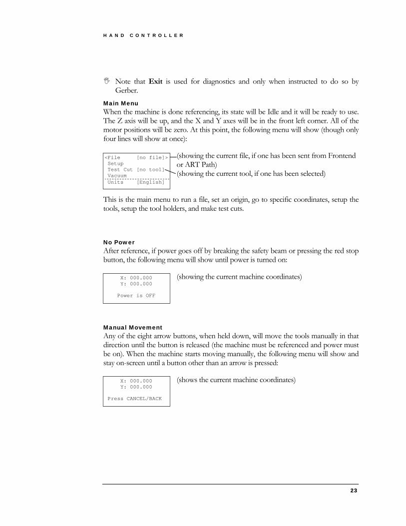
Main Menu When the machine is done referencing, its state will be Idle and it will be ready to use. The Z axis will be up, and the X and Y axes will be in the front left corner. All of the motor positions will be zero. At this point, the following menu will show (though only four lines will show at once):
(showing the current file, if one has been sent from Frontend or ART Path) (showing the current tool, if one has been selected)
<File [no file]> Setup Test Cut [no tool] Vacuum
X: 000.000 Y: 000.000 Power is OFF
Units [English]
X: 000.000 Y: 000.000
This is the main menu to run a file, set an origin, go to specific coordinates, setup the tools, setup the tool holders, and make test cuts.
No Power After reference, if power goes off by breaking the safety beam or pressing the red stop button, the following menu will show until power is turned on:
(showing the current machine coordinates)
Manual Movement Any of the eight arrow buttons, when held down, will move the tools manually in that direction until the button is released (the machine must be referenced and power must be on). When the machine starts moving manually, the following menu will show and stay on-screen until a button other than an arrow is pressed:
(shows the current machine coordinates)
Press CANCEL/BACK

H A N D C O N T R O L L E R
24
Origin The origin marks the point on the machine where the 0,0 point on the next substrate will register when it is run. The default origin is the reference point of the machine (the front left corner). The origin will need to be changed, for example, when a substrate must be cut in the middle of a large sheet because the edges of the board have already been used.
To set or check the origin, go to the following menu:
Run W/Contouring Run <Origin> Go To
<Set Here> Show Current Show Lower Left Show Upper Right Show Lower Right Show Upper Left
ORIGIN
<File [filename]> Setup Test Cut [tool] Vacuum Units [English]
VIEW LOWER
LEFT UPPER RIGHT
Set Here changes the origin to the current position of the Laser Pointer.
Show Current moves the Laser Pointer over the current origin.
The last four menu items move the Laser Pointer to the four corners of the substrate.
Vacuum Vacuum suction holds the material stationary on the table while the substrate is being produced. Vacuum must be turned on before running the job file, and can be turned off after. To control the vacuum, go to the following menu:
<Control[Automatic]> Turn On/Off
<Automatic> Manual
File [filename] Setup Test Cut [tool] <Vacuum> Units [English]
ZONE
Automatic makes the vacuum electrically turn on when the file begins running and shuts it off when it is done. Automatic only works if the electrician has used a magnetic starter for the blower and has wired it to the control box. Manual relies on the operator to control the vacuum.
Turn On/Off electrically turns the vacuum on or off, depending on its current state.
H A N D C O N T R O L L E R
25
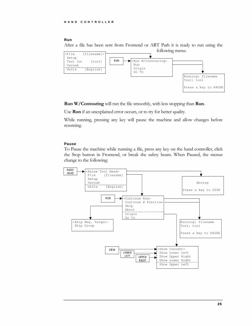
Run
<Run W/Contouring> Run Origin Go To
<File [filename]> Setup Test Cut [tool] Vacuum
After a file has been sent from Frontend or ART Path it is ready to run using the following menu:
RUN
Running: filename
Units [English]
Tool: tool Press a key to PAUSE
Run W/Contouring will run the file smoothly, with less stopping than Run.
Use Run if an unexplained error occurs, or to try for better quality.
While running, pressing any key will pause the machine and allow changes before resuming.
Pause To Pause the machine while running a file, press any key on the hand controller, click the Stop button in Frontend, or break the safety beam. When Paused, the menus change to the following:
<Raise Tool Head> File [filename] Setup Vacuum Units [English]
<Continue Run> Continue @ Position Skip Abort Origin Go To
RUN
Moving Press a key to STOP
Running: filename Tool: tool Press a key to PAUSE
<Show Current> Show Lower Left Show Upper Right Show Lower Right Show Upper Left
VIEW LOWER
LEFT UPPER RIGHT
RAISE HEAD
<Skip Reg. Target> Skip Group

H A N D C O N T R O L L E R
26
Main Menu:
Raise Tool Head moves the tool head up as high as it can go. This provides the operator access to the material and the tools. It also gives the tools clearance when moved across the material.
Test Cut is not available when Paused.
File Menu:
Continue Run resumes the file from where it was paused. If any changes are made to the tool setup while Paused, those changes take effect.
Continue @ Position is only available during an interrupted print registration operation. This will resume scanning from the current location of the pointer. You must have manually positioned the pointer over the registration dot before selecting this menu item.
Abort cancels the file and puts the machine back in an Idle state.
Origin / Set Here is also not available when Paused.
Skip Menu:
The Skip Menu is only available in an interrupted print registration operation.
Skip Reg. Target will skip the current registration dot. This is likely required due to a poorly printed target dot or a damaged target dot. This will allow you to continue scanning the rest of the registration dots.
Skipping targets may affect the scale or skew of the job material and alter cut quality.
Skip Group will skip the entire group of targets and its image and cut data. This allows a badly printed image and cut data to be ignored in a step and repeat pattern.
Go To To move to specific coordinates on the machine, use the following menu:
<File [filename]> Setup Test Cut [tool] Vacuum
Run W/Contouring Run Origin <Go To>
<Retract> Reference Absolute Position Relative Position Sensing Height
RETRACT ABS 0,0
Units [English]

H A N D C O N T R O L L E R
27
Retract moves the tools to the back left corner of the machine (for loading/removing material).
ABS 0,0 moves the tools to the front left corner of the machine (where it is just after reference).
Absolute Position moves, relative to ABS 0,0, the X and Y coordinates that are entered. The default X and Y coordinates to be entered are the current machine coordinates.
Relative Position moves, relative to the current position, the X and Y coordinates that are entered. The default X and Y coordinates to be entered are both 0 (zero).
Sensing Height lowers the tool head to the registration sensor working height. This menu is available if the optional registration sensor is present and allows you to adjust the sensor sensitivity while over a printed sheet at the correct height. See “Testing the sensitivity of the registration sensor” on page 70 for complete instructions.
To raise the tool head, turn the power back on and hold any arrow key to enter slew mode and the head will automatically rise. Setup To change material/tool parameters, the current tool, or tool/holder calibration values, use the following menus:
<Tool Settings> Holder Settings Material [0.000] Cut Mat [0.000] Machine Settings
File [filename] <Setup> Test Cut [tool] Vacuum Units [English]
<Tool [tool]> Pressure[00.0x +y] Depth [0.000] Vel. [00.00xy +z] Blade Len. [0.000] Calib. [0.000] Angle [-000.000] X/Y Dwell[000/000] U/D Dwell[000/000] Holder [0] Daylight [0.000] Activate
SETUP
<H1 Angle[-000.000]> H2 Angle[-000.000] H3 Angle[-000.000]
TOOL FORCE
DEPTH SPEED

H A N D C O N T R O L L E R
28
Setup Menu:
Material* and Cut Mat* enter the current thickness.
Holder Settings Menu:
H1... Angles enter a new angular correction for a holder. This should only be changed by Gerber service personnel.
Tool Settings Menu:
Tool selects a new current tool from a list of tools on the machine. The current tool affects which settings are shown and which tool will be used for a test cut.
All of the following settings apply to the current tool: Pressure* enters new X and Y tool pressures.
Depth* enters new X and Y tool depths.
Both Pressure and Depth show only one value if the X and Y values are the same. If the values are different, both show the X value and indicate +y (or –y) if Y is more (or less) than X.
Vel.* enters new X/Y and Z tool velocities. Vel. shows only the X/Y value and indicates +z (or –z) if the Z value is set to its max (or less).
Blade Len. enters a new blade length. This should be the value marked on the gauge that was used to set the blade in the collet. A tool’s blade length should not need to be changed if the same gauge is always used when replacing blades. See Figure 11.
Calib. enters a new calibration. This should be marked on the tool. See Figure 11
Angle enters a new angular correction. Use Test Cut / Angle Test or Test Cut / Circle Test to determine if the current value is correct or needs to be adjusted. A positive value corrects the tool counter-clockwise (looking down on the tool) and a negative value corrects the tool clockwise.
X/Y Dwell enters new delays when one line finishes before starting another line. These delays are usually required for ink pens to provide high quality plots.
U/D Dwell enters new delays when the tool is extended (Down) or retracted (Up) pneumatically.
Holder enters which holder is the default (or only) location for the tool.

H A N D C O N T R O L L E R
29
Daylight enters the clearance between the top of the material and the tip of the tool when moving to another location. See Figure 11.
* If the machine is Idle, Material, Cut Mat, Pressure, Depth, and Vel. only apply to a test cut. If the machine is Paused, changing these values will change the settings in the resumed file.
ToolCalib
BladeCalib
Machine Surface
MatMaterial
Day Light
Figure 11
Activate will turn the current tool on. This is used only on tools that can be activated and need adjustment. An example is the reciprocating knife which needs to be activated to adjust the lubricator.

H A N D C O N T R O L L E R
30
Machine Settings Menu:
Tool Settings Holder Settings Material [0.000] Cut Mat [0.000] <Machine Settings >
<Adjust to Pointer> Adjust to Sensor Surface [-0.000] Use Table Map [Yes]
File [filename]
MAP
<Setup> Test Cut [tool] Vacuum Units [English]
SETUP
Adjust to Pointer is used to adjust the location of the tools relative to the visible laser pointer. If the cut data origin point is not aligned with the visible dot then you can move the cut data relative to the pointer position. Enter values that move the cut data toward the visible dot. If the cut data is 0.12 inches to the right and 0.06 inches below then enter -0.12 for X and 0.06 for Y to move it left and up. See “Aligning the visible pointer” on page 74 for complete instructions.
Adjust to Sensor is used to adjust the location of the tools relative to the registration sensor. If the cuts are not aligned to the registration dots then the cut data can be adjusted in the same manner as described for the pointer position above. Note that this menu item is only available if the optional registration sensor is on the machine. See “Aligning the registration sensor” on page 75 for complete instructions.
Surface is a future option. Values should remain at zero unless directed by a service technician. When available, Surface will allow you to set the thickness of the top of the table on machines where the surface can be milled. Each time you machine a small amount off the surface, you reduce this number by the amount you machined off.
Use Table Map: After a machine is manufactured the surface flatness is measured and recorded. This Table Map may be used while operating to compensate for the measured errors in flatness. This feature can be turned on or off from this menu.
H A N D C O N T R O L L E R
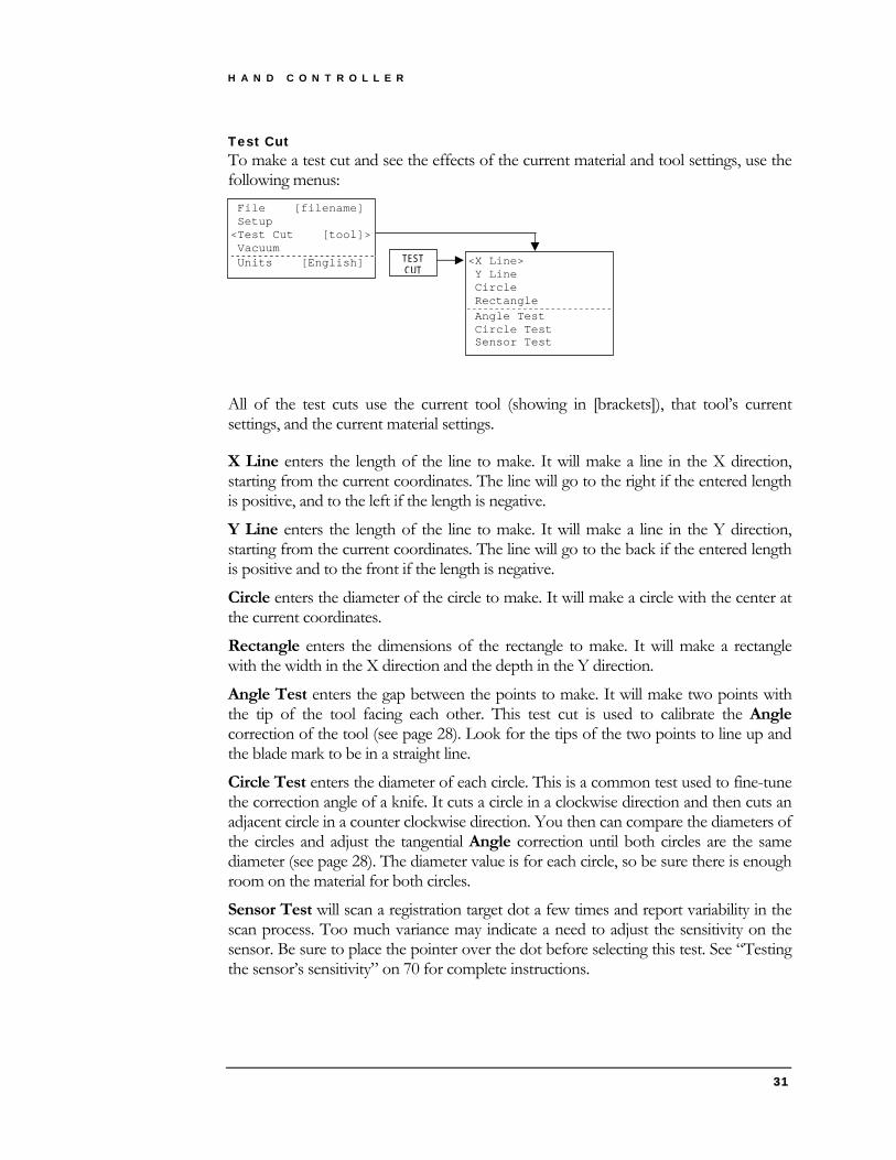
Test Cut To make a test cut and see the effects of the current material and tool settings, use the following menus:
File [filename] Setup <Test Cut [tool]> Vacuum Units [English] TEST
CUT <X Line> Y Line Circle Rectangle Angle Test Circle Test Sensor Test
All of the test cuts use the current tool (showing in [brackets]), that tool’s current settings, and the current material settings.
X Line enters the length of the line to make. It will make a line in the X direction, starting from the current coordinates. The line will go to the right if the entered length is positive, and to the left if the length is negative.
Y Line enters the length of the line to make. It will make a line in the Y direction, starting from the current coordinates. The line will go to the back if the entered length is positive and to the front if the length is negative.
Circle enters the diameter of the circle to make. It will make a circle with the center at the current coordinates.
Rectangle enters the dimensions of the rectangle to make. It will make a rectangle with the width in the X direction and the depth in the Y direction.
Angle Test enters the gap between the points to make. It will make two points with the tip of the tool facing each other. This test cut is used to calibrate the Angle correction of the tool (see page 28). Look for the tips of the two points to line up and the blade mark to be in a straight line.
Circle Test enters the diameter of each circle. This is a common test used to fine-tune the correction angle of a knife. It cuts a circle in a clockwise direction and then cuts an adjacent circle in a counter clockwise direction. You then can compare the diameters of the circles and adjust the tangential Angle correction until both circles are the same diameter (see page 28). The diameter value is for each circle, so be sure there is enough room on the material for both circles.
Sensor Test will scan a registration target dot a few times and report variability in the scan process. Too much variance may indicate a need to adjust the sensitivity on the sensor. Be sure to place the pointer over the dot before selecting this test. See “Testing the sensor’s sensitivity” on 70 for complete instructions.
31

F R O N T E N D S O F T W A R E
32
Frontend Software
Chapter
4 Setting up files to run on the machine.
he Frontend software is an operator-friendly Windows program that is used to open CAD files, make modifications, create layouts, setup jobs, and send these jobs to the machine to be run. T
Throughout this chapter, you will see icons like these ing shortcuts. Frequently used menu items are
through buttons at the top of the screen, through key presses, and/or through right-clicks of the mouse.
indicataccessible
I C O N K E Y
Button
Key press
Right-click
J + Ctrl
Opening a CAD File To run a file, you must first transfer the design from your CAD system to Frontend.
The CAD file must be saved either to a network area that the machine can access or to a floppy disk. Once an output file is created, it can be opened in Frontend in several ways, using either Today’s Files or the File / Open menu.
Frontend reads these file formats: HPGL, IPC, DXF, DDES2, CFF2
Today’s Files Most people tend to work their way through the list of jobs they need to produce
that day. They tend to output a job file from their CAD, run that file, and then move on to the next job file in the list. For such people, Today’s Files is ideal because it only shows job files that have today’s date.
Auto Load is the easiest way to use Today’s Files. When Auto Load is turned on, clicking the Today’s Files button will open any job files that have
not already been opened or that have been updated. To turn on (or off) Auto Load, go to the File / Options / Miscellaneous menu (see page 45).

F R O N T E N D S O F T W A R E
33
Another way to open Today’s Files is to click the down arrow next to the Today’s Files button. A list of Today’s Files will appear under the button,
and clicking on one of these files will open it. Files that have already been opened will have a check mark. This list is also available by going to the File / Today’s Files menu.
The last way to open Today’s Files is to go to the File / Today’s Files menu and then to click on one of the folders listed underneath the files. This will open the folder in Windows Explorer. Double-clicking one of the files will open it. Here you can also delete and rename files.
Windows Explorer shows all files, not just today’s.
There are two ways to setup the folder(s) that Today’s Files looks in. Using Windows, you can create a shortcut to your job file folder and place the shortcut in the Frontend Software folder (usually C:\Program Files\Frontend). You can use multiple shortcuts if you have multiple job file folders. If you do not create any shortcuts, Today’s Files will look in the folder where you last opened a file using Open..
Open To open a file without using Today’s Files, go to the File / Open
menu. In the dialog that appears, select the format of your job file from the Files of type pull-down list and find the job file folder using the Look in pull-down list.
Ctrl O +
Modifying a File Rotate To rotate a file, go to the Edit / Rotate menu. Enter the Angle of
rotation or accept the default of 90°. A positive angle rotates counter-clockwise and a negative angle rotates clockwise. The default Center of rotation, when rotating the entire file, is such that the lower-left remains the same after the rotation. You can change the center if you wa
F2
nt more control.
Mirror To mirror a file, go to the Edit / Mirror menu. Choose whether to mirror
Horizontal (right-to-left, across the Y Axis) or Vertical (top-to-bottom, across the X Axis). The Location of the Axis defaults to the center of the data, which keeps the origin in place, but the Location can be changed.
F3
Scale To scale a file, go to the Edit / Scale menu. Enter a new Scale Factor. A
value of 1.0 will make no change to the size. A value of 0.5 will half the size. A value of 2.0 will double the size, etc.
F4
Move F5 To move the coordinates of a file, go to the Edit / Move menu. Choose

F R O N T E N D S O F T W A R E
34
to move Relative or Absolute, and enter the New Origin. An Absolute move will put the lower-left at the New Origin, relative to 0,0. A Relative move will put the lower-left at the New Origin, relative to the Current Origin.
Step & Repeat To make many copies of a file, go to the Edit / Step & Repeat menu.
Enter the Columns as the number of copies you want in the X direction. Enter the Rows as the number of copies you want in the Y direction. Enter the Col. Spacing and Row Spacing as the spacing between each column and row. If the copies will touch or overlap, the Remove Common Lines option will be available. Checking this box will run the common line removal after stepping and repeating.
F6
All of the previous editing features apply to the entire file if no groups are selected. However, if any groups are selected (see page 38), they will affect only the selected group(s).
Remove Common Lines To remove or fix any lines that might be overlapping, go to the Edit /
Remove Common Lines menu. When the process is finished, a message will appear stating how many common lines were removed.
Sequence Slots To prevent the continuous motion of cutting slots (which tends to lift the slot
out of the material and tear it), go to the Edit / Sequence Slots menu. This process changes the sequencing of slots so that the small portion of the slot is cut last.
F7
F8
The process is customized using the screen shown in Figure 12. The Output color can be set to the original color, in which case the small portions remain on their original color but will be processed after everything else on that color. If a different output color is chosen, the sequencing is set in the Job Ticket by ordering the new output color after the original color.
Figure 12

F R O N T E N D S O F T W A R E
35
Channel Width Expansion To create tool paths for a channel that is wider than the available tool, go to the Edit / Channel Width Expansion menu. This process creates new tool lines on top of the original lines, making a path for the tool that will cut the required width.
Channels are defined using the screen shown in Figure 13. For each Input Color, specify a Channel Width (or leave it at zero if no expansion is required). Then specify the Tool Diameter that will be used to cut those channels (the tool must be narrower than the channel width).
Also specify an Overlap for the tool paths. The overlap is dependent on the tool width, and must be larger if the bottom of the tool is round or if the bottom of the channel must be smooth.
Figure 13
The Output Color is the color for the new lines (which must be setup in the Job Ticket in order to be cut). Choose Clockwise or Counter-Clockwise for the direction of the new tool paths.
Select Single To make changes to individual lines, go to the Edit / Select / Select Single menu. Click on all the lines that you would like to
change. If you make a mistake while selecting single lines, hold down the Shift key and click to De-Select Single lines. If you want to change lines that are all connected, hold down the Control key and use Select Chain. If you make a mistake while selecting chains of lines, hold down both the Shift and Control keys and click to De-Select Chains. Table 2 summarizes these four selection modes.
S + Ctrl
With any of these modes, holding down the mouse key and dragging a rectangle around lines will select (or de-select) every line contained within the rectangle.
F R O N T E N D S O F T W A R E
36
Mode Key(s) to Hold Down Cursor Appearance
Select Single (None)
De-Select Single Shift
Select Chain Control
De-Select Chain Shift + Control
Table 2
Select Insides, Select Outsides, and Select All are a few further select modes. Select Insides selects everything that is completely inside the extents
of something else. Select Outsides selects everything whose extents are not inside anything else. Select All selects everything on the screen.
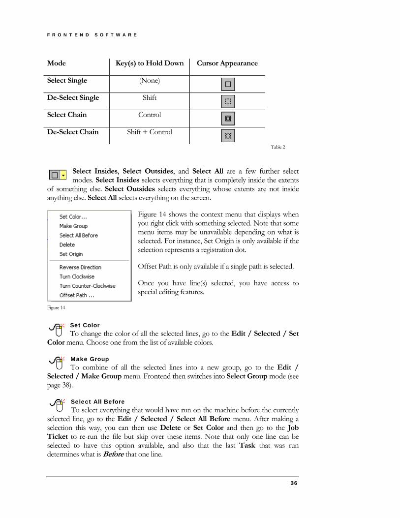
Figure 14 shows the context menu that displays when you right click with something selected. Note that some menu items may be unavailable depending on what is selected. For instance, Set Origin is only available if the selection represents a registration dot.
Offset Path is only available if a single path is selected.
Once you have line(s) selected, you have access to special editing features.
Figure 14
Set Color To change the color of all the selected lines, go to the Edit / Selected / Set
Color menu. Choose one from the list of available colors.
Make Group To combine of all the selected lines into a new group, go to the Edit /
Selected / Make Group menu. Frontend then switches into Select Group mode (see page 38).
Select All Before To select everything that would have run on the machine before the currently
selected line, go to the Edit / Selected / Select All Before menu. After making a selection this way, you can then use Delete or Set Color and then go to the Job Ticket to re-run the file but skip over these items. Note that only one line can be selected to have this option available, and also that the last Task that was run determines what is Before that one line.

F R O N T E N D S O F T W A R E
37
Delete To remove all of the selected lines, go to the Edit / Selected / Delete menu.
This action can only be undone by re-opening the file and starting over.
Set Origin To set the data origin to the center of a registration dot, first select the
registration dot circle (or one portion of the circle if it is segmented), and then go to the Edit / Selected / Set Origin menu. By setting the data origin to the center of a registration dot you make it easy to set the machine origin on the table by placing the laser pointer over the same dot and setting the origin there. The Selected /Set Origin option is not available if more than one item is selected.
Reverse Direction To swap the beginnings and ends of all the selected lines, go to the Edit /
Selected / Reverse Direction menu. To see the current direction of the lines in the file, use View / Line Directions (see page 41). On a Sample Maker, reversing a line’s direction is especially helpful when cutting narrow slots. When a narrow slot is cut in a continuous U shape, the material in the slot tends to lift up with the motion of the tool. However, if the last side of the slot is cut in the opposite direction, the material tends to hold together better.
Figure 15 shows a slot whose direction has been reversed. The slot on the left is the original configuration. The slot on the right has been modified so that it will be cut from bottom to top.
Figure 15
Turn Clockwise / Turn Counter-Clockwise To specifically set the direction of all the selected lines, go to the Edit /
Selected / Turn Clockwise or Turn Counter-Clockwise menu. These options are especially useful with a router, when the direction of cut must either go with or against the direction that the spindle turns.
Offset Path To offset a path, go to the Edit /Selected / Offset Path menu item. This is
useful if you are going to rout a shape and the cutter compensation was not done in the CAD system. You have the choice of doing an inside or outside offset and can choose the color of the offset.
End Select To end Select mode and return to normal mode, go to the Edit /
End Select menu, or click anywhere in the dark gray Frontend background.
Ctrl S +

F R O N T E N D S O F T W A R E
38
Select Group Select Group To make changes to a group, go to the Edit / Select Group menu
and click on a group. Click on all the groups that you would like to change. If you make a mistake while selecting, hold down the Shift key and click to De-Select Groups.
To make changes to a group, go to the Edit / Select Group menu and click on a group. Click on all the groups that you would like to change. If you
make a mistake while selecting, hold down the Shift key and click to De-Select Groups.
Additionally, double-clicking on a line in a group will select that group and go into Select Group mode.
Additionally, double-clicking on a line in a group will select that group and go into Select Group mode.
Table 3 summarizes these group modes. Table 3 summarizes these group modes.
Mode Mode Key to Hold Down Key to Hold Down Cursor Appearance Cursor Appearance
Select Group (None) or Control
De-Select Group Shift
Move Group (None)
Table 3
Once you have group(s) selected, you have access to special editing features:
Set Color Delete
Drag & Drop
End Select Group To end Select Group mode and return to normal mode, go to the
Edit / End Select Group menu, or click anywhere in the dark gray Frontend background.
Creating a Layout Insert To merge a separate file into the currently opened file, go to the
Separate groups are created by: Using Step & Repeat (see page 34) Using Make Group (see page 36) Inserting a separate file (see page 38) Pasting in a file or group (see page 39) Drag/dropping a group (see page 39)
Ctrl G +
Ctrl Ins +
+ G Ctrl
See page 39 for descriptions of these features.
See page 36 for descriptions of these features.
All of these editing features affect only the selected group(s): Rotate, Mirror, Scale, Move, Step & Repeat, Copy. To affect the entire file, End Select Group mode (see below).
F R O N T E N D S O F T W A R E
39
File / Insert menu. The Open dialog will appear. After a new file has been chosen, it will be inserted into the current file either to the right or to the top, wherever there appears to be more room. It will be available as a separate group.
Cut To remove a group and place it somewhere else, go to Edit / Cut.
Once the group is removed, use Paste (see below) to place it either in the original file or in a separate file.
Ctrl X +
Cut is only available if one or more groups are selected (see page 38).
Copy To duplicate a group and place the copy somewhere else, go to
Edit / Copy. Once the group is duplicated, use Paste (see below) to place it in a file.
Ctrl C +
Copy applies to the entire file if no groups are selected. However, if any groups are selected (see page 38), Copy will affect only the selected group(s).
Paste To place a group after using Cut or Copy (see above), go to Edit /
Paste. The group will be place in the current file either to the right or to the top, wherever there appears to be more room.
Drag & Drop The mouse alone can easily Cut and Paste (see above) using Drag & Drop. First, select at least one group (see page 38). Then click one of the lines in the selected group(s) and hold the mouse button down. Still holding the mouse button down, Drag the mouse to a new location (either in the original file or in a separate file). Let go of the mouse button where you want to Drop the group(s).
Save As To save a layout so that it can be reused, go to the File / Save As menu. In the
dialog that appears, select either HPGL or Plotlist from the Files of type pull-down list. HPGL is a common file format that other applications may support. Plotlist is an internal format specific to Frontend. Find the folder where you would like to save the file using the Look in pull-down list.
Ctrl V +
Test Cuts To create a quick file to run on the machine, go to the File / New / Test Cuts menu. Then specify which shape to create: X Line (horizontal), Y Line (vertical), Circle, or Rectangle. Enter the desired dimensions, and choose an Output Color.
Laser Test Cut Laser Test Cut is only valid for machines equipped with a laser. To create a convenient laser test cut, go to the File / New / Laser Test Cut menu. This will

F R O N T E N D S O F T W A R E
40
create a file with lines going in all 4 burn directions and a trim border for easy removal so the bottoms can be measured.
Laser test cuts are defined using the dialog shown in Figure 16. Line Length specifies the length of the four test cuts. Line Gap is the distance the endpoints are away from each other. Trim Spacing is the distance between the test cuts and the trim. Tack Width is the distance of the tack bridge in the trim line. Line Color is the color of the test lines and Trim Color is the color of the trim lines. Select OK to create the test cut.
Figure 16
Changing View Settings Zoom Window To get a closer view of a certain area of your file, go to the View /
Zoom Window menu. Click and hold the left mouse button down on the first corner of the window around what you want to view, then drag the mouse and let go of the mouse button on the second corner of the window.
Zoom Full Screen To view your entire file, use View / Zoom Full Screen menu.
Zoom Out To get a larger view and see more area of your file, go to the View
/ Zoom Out menu. The center of the view remains the same.
Zoom In To get a close-up view and see more details of your file, go to the
View / Zoom In menu. The center of the view remains the same.
Zoom Previous To return to the last view prior to this one, go to the View / Zoom
Previous menu.
Ctrl F +
Ctrl - +
Ctrl + +
Ctrl ◄ +
Ctrl W +
Material To show construction boundaries, go to the View / Material menu. Enter a Width, a Height, and coordinates for the lower-left Origin, and a rectangle of that size will be shown with your job file. This feature is convenient when making layouts. The

F R O N T E N D S O F T W A R E
41
dimensions are typically the size of your material or the size of the machine. This rectangle will not be produced with your file – it is only for assistance while in Frontend.
Line Types If you want to change the way your line types display, go to the View / Line Types menu. With this checked, your line types will appear as they were output. Without, all your line types will appear as solid (continuous) lines. The lines will be produced exactly as they appear.
Line Directions To indicate the direction of all of your lines, go to the View / Line Directions menu. Arrows will be shown on top of all your lines, showing their direction. In addition, a small circle will be shown at the start point of each line. This view mode is most often used with the Reverse Direction editing feature (see page 37). The arrows and circles will not be produced with your file – they are only for assistance while in Frontend.
Points as Stars To see if there are any points in your job file, go to the View / Points as Stars menu. Any points will appear as large asterisks (*). To removes points that overlap other lines, try turning on the Point Filter (see page 42) or using Remove Common Lines (see page 34). To remove left-over points, try using Select Single and Delete (see page 35). The stars will not be produced with your file – they are only for assistance while in Frontend.
Colors To turn off certain colors so they will not be output use the colors menu. This
is accessed via the View / Show Colors menu or the toolbar. If you select the drop down arrow on the toolbar icon then you can turn one color on or off at a time. If you click on the button then a dialog will show allowing you to turn on or off multiple colors before dismissing the dialog box.
Only colors that exist in the current file are available to be turned on and off. If you select the All checkbox then all used colors will be turned on at once.

F R O N T E N D S O F T W A R E
42
Changing File Options Options To change the way that files are opened, go to the File / Options menu. There you will see three tabs with different functions (see Figure 17).
Optimization Optimizations, applied when a file is opened, clean up the data and improve the speed of the machine.
Optimize Data allows all of the Filters to be turned off or on with one click.
Save as Default, when checked, will cause any changes of the settings to be saved for the future. If left unchecked, any changes will be lost when you exit Frontend.
Figure 17
Filters:
Remove Common Lines eliminates lines on top of other lines. Lines that overlap are converted to a single line. Also see page 34.
Point Filter removes points that cause lines to be broken into a series of shorter lines.
Pen Up Arcs applies only to HPGL files. This should be turned on if arcs are being drawn that were not in the original CAD file.
Link Duplicate Colors reorganizes data of the same color. The results are invisible to the user.
Jagged Arc Filter applies only to HPGL files from the CAD package Score!. This smoothes arcs that cannot be created using Arc Fitting (see below) because they have too much of a jagged staircase-like geometry.
Sequencing optimizes the path of the data. This is an important filter in terms of speed of the machine. It also influences the effectiveness of other filters.
Strip Extra Pen Ups removes extra movements while the tool is in the air. With this option turned off, any pen-up moves will be allowed and the origin may not move to the lower left even if Origin Lower Left is checked.

F R O N T E N D S O F T W A R E
43
The Coalesce filter removes small gaps between endpoints. Any gaps larger than the setting will be left alone. This number should be set no higher than the tolerance on the product because data could be altered by this amount.
Arc Fitting restores arcs that have been output as a series of small lines. It also will smooth out ellipses and splines that were vectored. Using Aggressive will create the most arcs, but will also distort the data the most. Using Standard will conservatively create arcs. Using None will turn off Arc Fitting.
Sequence Slots automatically recognizes slots in RSC type boxes. If the width of the slot is less than or equal to the setting here then the small connecting line will be cut last. This feature minimizes tearing of the liner on corrugated materials. This option should be left off for lasers and routers. Also see page 34.
Transforms:
Rotate 90 rotates each file counter-clockwise by 90 degrees.
Origin Lower Left moves each file so that the left-most point is at X=0 and the lowest point is at Y=0. This means that every coordinate in the file becomes zero or greater. The Origin that is set on the machine relates to (0,0) in the file. Using this filter guarantees that the job file will always be made, starting from the Origin, towards the right and back of the machine.
Scale changes the size of each file by the scale factor set here. A value of 1.0 will make no change to the size, while a value of 0.5 will half the size, and a value of 2.0 will double the size, etc. If the box is checked, the file will be scaled by the factor. If it is unchecked, no scaling will be done and the value is ignored.
Font:
Fixed and Proportional are different styles applied to inherent text (versus vectored text). Fixed makes all the characters the same width. Proportional is fancier.

F R O N T E N D S O F T W A R E
44
DXF Filters The DXF Filters tab contains special settings for importing DXF files (see Figure 18).
Map Colors Using defines the way that colors and layers in the DXF file are assigned to colors in Frontend. Using Colors, data is assigned to its original colors, as best they can be. Using Layers, data is assigned sequentially to new colors. The best setting is typically Colors. Other settings can lead to random colors and make it difficult to setup a consistent Job Ticket.
Show Hidden Layers, when checked, includes layers that are marked as hidden in the DXF file.
Map Text to sets a color to assign all text. If this is unchecked, text will be assigned a color like other data.
Figure 18
Map Dimensions to sets a color to assign all dimensions. If this is unchecked, dimensions will be assigned a color like other data.
Put Overflow on sets a color to assign any data once all the colors have been used.
Units specifies the units that the DXF file was saved in and affects the import scaling.
Frontend will reliably import genuine AutoCAD DXF files saved in R13 or LT format, or earlier. This also assumes it is a basic structural file containing lines, polylines, arcs, circles, and text. Viewports, 3D objects, wire-frames, solids, etc. are not compatible.
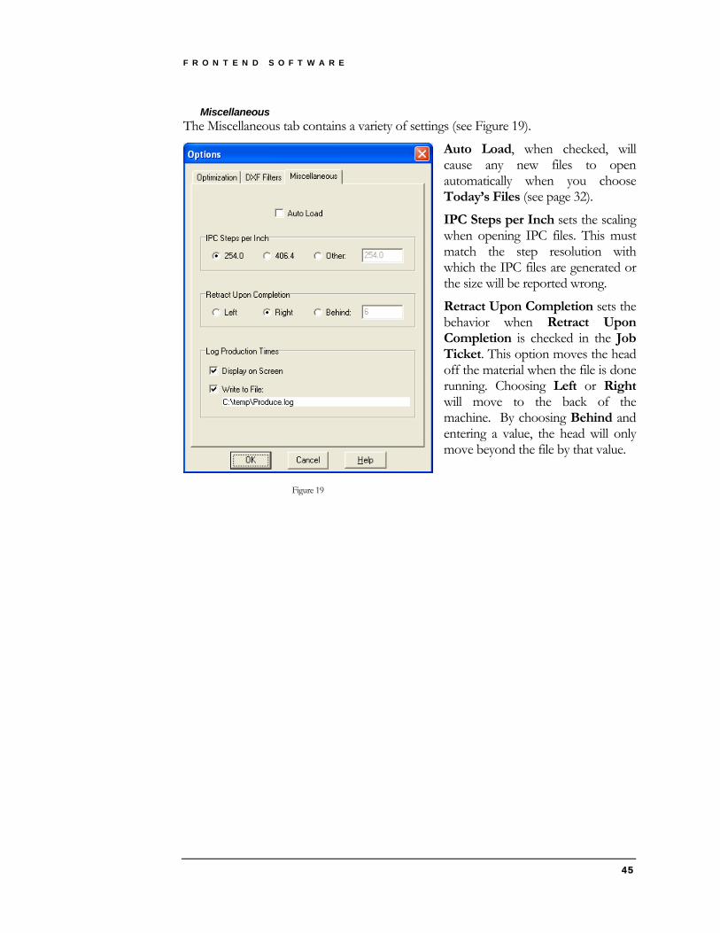
F R O N T E N D S O F T W A R E
45
Miscellaneous The Miscellaneous tab contains a variety of settings (see Figure 19).
Auto Load, when checked, will cause any new files to open automatically when you choose Today’s Files (see page 32).
IPC Steps per Inch sets the scaling when opening IPC files. This must match the step resolution with which the IPC files are generated or the size will be reported wrong.
Retract Upon Completion sets the behavior when Retract Upon Completion is checked in the Job Ticket. This option moves the head off the material when the file is done running. Choosing Left or Right will move to the back of the machine. By choosing Behind and entering a value, the head will only move beyond the file by that value.
Figure 19

F R O N T E N D S O F T W A R E
46
With Log Production Times, the run time and lengths of each color are reported after a file has finished running. The production log can be Displayed on Screen (and printed, see Figure 20) or Written to File, or both.
The log file is always called Produce.log, but the location can be changed by clicking on the name. The log file can be imported into a spreadsheet (as tab-separated text).
Figure 20
Units To set the units in which to work, go to the File / Units menu. Choose Inch to work in inches or Metric to work in millimeters.
Language To change the language that the Frontend program displays, go to the File / Language menu and select from the available languages.
Controlling the Machine Hand Controller To access the Hand Controller through Frontend, go to the File /
Hand Controller menu. The screen that will appear will look just like the physical Hand Controller and will function the same (see the Hand Controller chapter). However, take your time pressing buttons because the display is slower than it is with the physical Controller.
Ctrl H +
Use caution! Unlike any other functionality in Frontend, buttons on the Hand Controller screen can move the machine.

F R O N T E N D S O F T W A R E
47
Running a File The Job Ticket
Ctrl J + To run a file, go to the File / Job Ticket menu (see Figure 21).
If you have used the material before and do not need to make any changes, simply:
1. Choose the correct Material, Caliper, and Color Map from your library of settings.
2. Verify that all of the values in the job listing look correct.
3. Press Run.
Anytime that you make changes to a job, follow this sequence:
1. Use the Material tab to define the material and options (see page 48).
2. Use the Settings tab to modify or add rows (see page 50).
3. Use the Color Map tab to associate the file colors to the job rows (see page 51).
4. Press Save (see page 52).
The following illustrations will show the three pages of the Job Ticket and describe some of the available settings and options.

F R O N T E N D S O F T W A R E
48
Material
Figure 21 The Material tab (see Error! Reference source not found.) shows the current library selections, some global options, the current filename, and a listing of all the settings for the job. It allows you to select a Material and Caliper from your library of settings or setup a new job.
The easiest way to create a new job is to first pick a similar job using the Material and Caliper lists. Next, enter any changes for the new job. Then press the Save button (see page 52) and enter the Material and Caliper under which to store the new job. Each time you save a new set of parameters, you are adding to your library of jobs.
The Caliper you select in the Job Ticket is an important parameter. It is used to define the top of the material on the Table. All the depths you specify for the tools are in
relation to the top of the material. What is not so obvious is this caliper is used by the machine to calculate the tool-up position during tool-up moves to the next tool-down position on the substrate. The net result is that if you put material that is thinner than the selected caliper on the table,
no harm is done. However, if you place material that is thicker than the selected caliper on the table, you risk scratching the top of the material or worse yet, breaking the knife blade during tool-up moves.
To change a tool’s raise height, see the Daylight tool setting on page 29.

F R O N T E N D S O F T W A R E
49
The Mat thickness must be set to the measured thickness of the underlay material on the machine. Its setting affects the depths that the tools achieve.
The Color Map dictates which color in the job file will be used by each row in the job. The color assignments sometimes change when the job file comes from a different CAD system or a different customer. Check the Color Map before running the job.
The Preserve Groups option is used to specify how groups are produced. With this option on, each group in a layout will have all operations completed before the next group is started. If you turn this option off, each operation will be performed across all groups before moving on to the next operation.
The Sort by Pressure option will affect any operation that has a different pressure for the X and Y directions. If the option is on then all the X lines are done as a group and then all the Y lines are done as a group. This has the benefit of higher quality creasing at the expense of less path optimization.
The Retract Upon Completion option is used to move the head to the back of the machine when the job has finished running. This option simplifies removing the processed material and loading the new material for the next job. To define how far back the head should move using this option, go to the File / Options / Miscellaneous menu (see page 45).
The Flutes/Grain button shows the direction the flutes of corrugated products or the grain of carton stock should be placed on the table. Pressing this button will swap any differential depths or forces in each of the job listing rows. The button will then show the new flute direction. The Flutes/Grain button only appears when using certain materials such as corrugated or carton stock.
The job listing at the bottom of the screen indicates how the job will be run. Each row represents a different operation and shows a summary of its settings. Each operation will happen on the machine in the order it is listed. To change this order, just click on a row and drag it to a new position in the list.
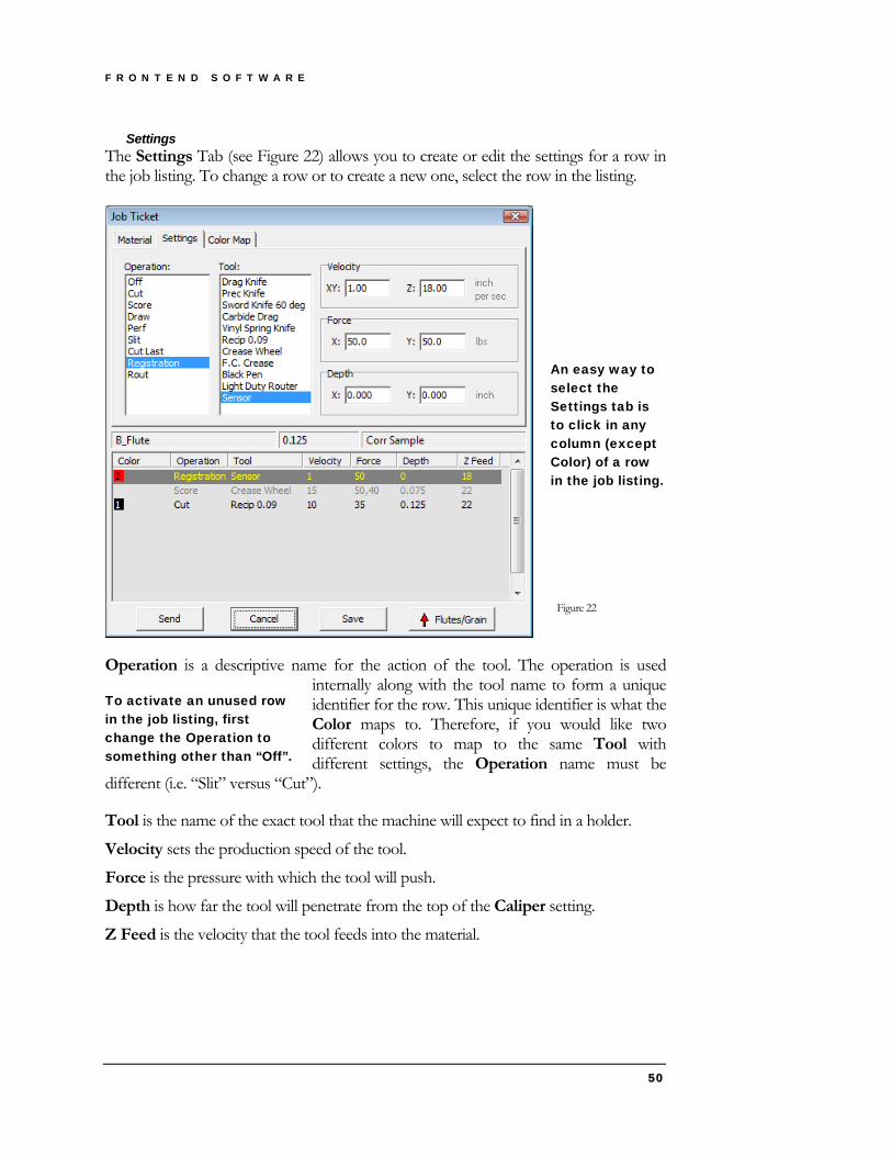
F R O N T E N D S O F T W A R E
50
Settings The Settings Tab (see Figure 22) allows you to create or edit the settings for a row in the job listing. To change a row or to create a new one, select the row in the listing.
An easy way to select the Settings tab is to click in any column (except Color) of a row in the job listing.
Figure 22
Operation is a descriptive name for the action of the tool. The operation is used internally along with the tool name to form a unique identifier for the row. This unique identifier is what the Color maps to. Therefore, if you would like two different colors to map to the same Tool with different settings, the Operation name must be
different (i.e. “Slit” versus “Cut”).
To activate an unused row in the job listing, first change the Operation to something other than “Off”.
Tool is the name of the exact tool that the machine will expect to find in a holder.
Velocity sets the production speed of the tool.
Force is the pressure with which the tool will push.
Depth is how far the tool will penetrate from the top of the Caliper setting.
Z Feed is the velocity that the tool feeds into the material.

F R O N T E N D S O F T W A R E
51
Color Map The Color Map tab (see Figure 23) allows you to associate colors in the file with Operation/Tool combinations. To change a row or to create a new one, select the row in the listing. Then check the boxes next to the colors in the top list. If desired, the
same color may be used to do more than one Operation/Tool combination. If a row appears grayed out, it is merely because none of the colors in the row matches the current file.
Always set the Color Map last.
An easy way to select the Color Map tab is to click in the Color column of a row in the job listing.
Figure 23

F R O N T E N D S O F T W A R E
52
Saving Jobs Saving the current settings to a library is as simple as filling the rows in a job listing and then selecting the Save button. This will present the following dialog where you can define the settings (see Figure 24). You will notice there are two pull-down lists in the dialog: Material and Caliper.
The caliper should be set to the thickness of the material you want to run. The material should describe the substrate you are cutting. It is important to understand that for each material you define, you can have many calipers. Therefore, each combination of Material and Caliper has a unique job associated with it.
Figure 24
For materials like foam products you may want to name your materials in a way that defines its unique properties, like the material type and density: For example:
• 2.0 PCF polyethylene
• 3.0 PCF polyethylene
• 1.0 PCF urethane
This descriptive list lets the operator know the material and its density in pounds per cubic foot. Now for each of these materials you could have a caliper list that would define settings for each nominal thickness you plan on processing.
It is important to define the meaning of nominal thickness mentioned above. Many foam products are described as 2″ or 3″. In actuality they can vary up to ¼″ from this nominal thickness. So, to set up a 2″ nominal material you would set the caliper to 2.250 and all your settings would reflect this thickness. By selecting the maximum thickness, you will guarantee the tool raise height is enough to clear the thickest material in the range. (Also see Caliper on page 48).
For materials like corrugated, you may set your material names like:
• 175 # test
• 200 # test
• 275 # test
This is a convenient way to describe the board in terms of the liner weight. This method is suggested because the liner weight affects the crease pressure. Under each liner weight, you would put the calipers.

F R O N T E N D S O F T W A R E
53
Making a Crease Matrix A crease matrix placed underneath your material can improve the quality of creasing. To create a crease matrix, go to the Edit / Crease Matrix menu. Enter your parameters and options in the screen that appears (see Figure 25). Press OK. A separate crease matrix file will be created with the same name as your substrate but ending in .MAT.
To use the crease matrix file:
1. Run the matrix file using the same material as your substrate, with the same job settings.
2. Leave the vacuum on.
3. If you cut a border, remove the excess.
4. Overlay new material for your substrate.
5. In the Job Ticket, change the Mat caliper to include the crease matrix thickness.
6. Without changing the Origin on the machine, run the substrate file. Figure 25
7. Remember to return the Mat caliper to its original value when you are finished using the crease matrix.
The following describes the Crease Matrix parameters and options (see Figure 25).
Dimensions:
Caliper is the thickness of the substrate material.
Rule is the width of the crease tool that will be used when making the substrate (and also the width of the creasing rule in the die, eventually).
Channel Offset sets the distance from the end of the crease line in the file to where the creasing channel stops (see Figure 26). This helps to keep the matrix together.
Figure 26

F R O N T E N D S O F T W A R E
54
Border Offset determines how far outside the maximum dimensions of the substrate the border rectangle will be cut (see Cut material border).
Across Grain adds an extra amount to the channel width when the creasing direction is across the grain of the material. Use the Grain button to indicate which way the grain is currently facing on the machine.
Options:
Split touching lines, when checked, breaks up channels wherever crease lines intersect. To compare how creasing channels would be formed at an intersection point with this setting off versus on, see Figure 27.
Figure 27
Cut material border, when checked, creates a rectangle to cut out around the substrate. This border will be cut with the same settings as the creasing channels. Use this feature to be able to remove the material around the crease matrix, to improve the vacuum hold-down for the substrate. With this on, you must enter a Border Offset.
Draw extents, when checked, draws a 0.5 inch “L” shape at the four corners of the substrate, showing where the maximum dimensions are. With this checked, you must select an Output color for Drawing, which is setup to Draw in the Job Ticket. Use this feature to help locate the edges of the crease matrix when placing the substrate material on top.
Ends:
Choose one of the two options, Round or Triangle, for the shape of the creasing channel ends (see Figure 28).
Figure 28
Formula:
To understand the Formula for the crease matrix channel width, see Figure 29. The gap in the crease matrix must be wide enough for the creasing tool (Rule) plus two
layers of the substrate material (Caliper), plus a small space on both sides so that the edges of the channel do not tear the material. The amount of extra space on the sides of the channel can be configured in the Formula, by specifying a fraction of the Caliper.
Figure 29

F R O N T E N D S O F T W A R E
55
Colors:
For Input color(s) of crease lines, select the color(s) in the file that contain the creases lines.
For Output color for Cutting, select a color which is setup to Cut in the Job Ticket. This knife tool will be used both to cut the creasing channels and to cut the outside border (if Cut material border is turned on).
For Output color for Drawing, select a color which is setup to Draw in the Job Ticket. This pen will be used to draw the extents (if Draw extents is turned on).

Chapter
5 U S I N G T H E T O O L S
Using the Tools T3= Total Tooling Technology.
he M-Series has a flexible tooling system consisting of various holders for knives, wheels, pens, and a light duty router. These holders fit into the tool positions on the tool head. In addition there is a system to mount various presser feet used to hold the material flat, guard the knife blades, and in some
cases control the cut depth.
T Tool Head The tool head consists of three tool locations and a laser pointer. Each tool location has a 30mm bore to accept tool holders of that diameter. The left location is reserved for the light duty router tool. All the positions are driven by a single motor to keep the tool tangent to the direction of travel. Each position has a pneumatic actuator to lower the tool by 1.25″ when it is activated for use.
The tool head has three tools installed (see Figure 30). The tools are held in place with a knurled retaining ring at the top. This ring is tightened until it presses down on the tool holder orientation pin (see Figure 31).
Retaining Ring
Orientation Pin
Figure 30 Figure 31
56

U S I N G T H E T O O L S
Some tools require the use of a presser foot to keep the material flat during operation of the machine (see Figure 32). This is important when using knife tools because, if the material is warped, the blade could scratch it during tool-up moves to the next cut location. The presser foot mounts onto the dovetail on the housing corresponding to the tool location. To find the dovetail, lift on the tool head cover to expose the dovetails. Now slide the presser foot up all the way until it bottoms out. Then tighten the two thumbscrews to hold it in place.
Presser feet also act as a safety guard around sharp blades.
Figure 32 Presser Foot
The Tools There are a number of different tools available for the M-Series machines. It is doubtful your machine will have all possible tools, so skip any descriptions that are not relevant. Refer to Appendix C – for a complete chart of available tools.
One common attribute of all the tool holders that contain knife blades is that the knife blade always cuts towards the tool holder orientation pin (see Figure 31). That is to say, you always install a knife blade with the sharp edge facing towards the orientation pin.
WARNING The safe and correct way to service or adjust the tools is to depress the red
stop button before reaching into the machine work area to touch the tools. Before servicing the reciprocating knife, disconnect the pneumatic connection to render it safe.
Reciprocating Knife There are four different reciprocating knives available. They are differentiated by the amount of travel and the strokes per minute (SPM).
For general purpose corrugated cutting on both felt and PVC sacrificial underlay use the 0.032’ 7000 SPM knife. For applications that will make heavy use of double and triple wall corrugated the 0.090″ 7000 SPM knife on ¼″ felt is recommended. For all foam cutting applications on either felt or PVC use the 0.250″ 4000 SPM knife. For ejection rubber cutting use the 0.032″ 7000 SPM 5 degree bevel knife.
57
U S I N G T H E T O O L S
There are two blade-holding collets available for these knives, and your knife should have come with one of them or both as an option. One collet holds #11 X-ACTO™
blades and the other collet holds 0.062″ by 0.250″ shank carbide blades. Once you have selected the blade type that you are going to cut with, you must install it with enough of
the cutting edge exposed to fully penetrate the material thickness. A blade depth gauge is provided to help in the blade installation process (see Figure 33).
Figure 33
Begin by installing the blade in the collet with the two retaining screws loose. Remember to face the sharp edge towards the orientation pin. Then place the tool over the desired location on the blade depth gauge and lower it until the tool rests on the gauge. Now tighten the two retaining screws using the Bristol (spline) head key.
Now you must enter the Blade Length into the controller using the hand controller (see page 28).
For the X-ACTO blade the 0.400" settings is used for all materials up to C-flute. The 0.500" setting is for all materials up to Double-Wall and the 0.600" setting is for triple wall cutting. For the carbide blade, the setting is done using the flat bottom holes. For corrugated materials, the two holes on the left can be used. You will note that the body of the reciprocating knife does not fit into the counter bore on these two holes as they are designed for the drag knives, resulting in the blade protruding more than what is engraved on the depth gauge. The difference is 0.088" so if you set the carbide blade using the 0.312 position the blade will protrude 0.400". If you use the 0.562 position, the blade will protrude 0.650".
For the foam knife, you must use the dial caliper supplied with the machine to measure the blade protrusion from the bottom of the knife assembly. (Do NOT measure to the bottom of the blade collet). Enter the value read on the caliper into the controller as above.
Installing the Reciprocating Knives To tighten the Tool Head retaining ring on to the orientation pin of the reciprocating knife it is necessary to grip the tool in the adjacent location. This is because the top of the reciprocating knife is connected thru ball bearings to the knife body so gripping it will have no effect.
58

U S I N G T H E T O O L S
Drag Knife There are various drag knives available, some for folding carton and some for corrugated. They are all treated the same from the operational point of view. As always the knife blade is installed with the sharp edge facing toward the orientation pin. Depending on the thickness to be cut, select a flat bottom position in the blade depth gauge and rest the knife holder on the gauge. Be sure the blade rests on the bottom of the hole and tighten the blade retaining screws.
Now enter the Blade Length into the controller using the hand controller (see page 28).
Crease Wheel There are three different crease wheel holders, one for folding carton and two for corrugated. On all of these holders, spring plungers that press on the axle of the wheel retain the crease wheel. To remove a crease wheel, just grip it and pull the wheel off. To install a different wheel just push it back on until it ‘clicks’ into place. As the wheel has a very small amount of clearance in the holder, it is better to hold the wheel with the axle ends under your thumb and index finger. This gives you better control in aligning the wheel accurately with the holder.
The optional 2″ diameter wheel holder is a little different in that a 2″ wheel cannot fit into the tool sleeve on the tool head. In this case you mount the holder without the wheel into the tool head, lift the tool head cover, and then insert the wheel into the protruding wheel holder until it ‘clicks’ in.
Each holder takes wheels of the same diameter, so there is no need to change the Blade Length setting in the controller.
Ballpoint Pen The ballpoint pen holder holds a pressurized ink cartridge. To replace the ink cartridge just pull on the end of the ink cartridge holder until it pops out of the pen assembly. You will notice a knurled sleeve on the end opposite the ballpoint. Twist this sleeve to loosen and then grip the end of the ink cartridge and pull it out. Drop in a new cartridge and tighten the knurled sleeve to retain the cartridge. Then push this assembly back into the pen assembly until it ‘clicks’ into place.
To adjust the weight of the line while drawing, turn the adjusting knob on the top of the ballpoint pen assembly. Turning the knob downward increases the pressure on the pen and turning the knob upward decreases pressure on the pen.
Utility Blade Tools This description applies to both the straight and 45° bevel blade holders. This is an optional tool used for the production cutting of triple wall material at high speeds.
Use extreme caution when handling this tool as the blade is quite sharp.
59
U S I N G T H E T O O L S
There is no gauge for setting this blade as there are two locating pins in the blade holder that line up with two grooves in the utility blade. To install a blade, line up the grooves on the blade with the locating pins and tighten the retaining screws.
The blade holder is too large to fit into the tool sleeve on the tool head. This holder uses the optional drawbar assembly to retain it. First install the drawbar into the tool head and secure it using the retaining ring on the tool head. Then open the tool head cover and slide the utility blade up from the bottom into the tool position that contains the drawbar. Turn the blade holder while holding it in the up position until its orientation pin slips into the orientation slot in the tool head. At this time, tighten the retaining knob on the drawbar to securely hold the blade holder in place.
The locating pins control the utility blade protrusion, so there is no need to change the Blade Length setting in the controller.
After installing the blade, open the tool head cover and install the large presser foot (see Figure 32).
WARNING The safe and correct way to service or adjust the tools is to depress the red
stop button before reaching into the machine work area to touch the tools. Before servicing the Light Duty Pneumatic Router, disconnect the pneumatic connection to render it safe.
Light Duty Pneumatic Router The Light Duty Pneumatic Router tool is designed to cut a variety of rigid materials up to 1/2″ (12.7mm) thick. It comes with two collets: 3.175mm (1/8″) and 5mm to accommodate Gerber cutting bits in metric (3mm and 5mm) and English sizes (1/8"). Typical material applications include: 1/8" Dibond® and 1/4" Alumalite™, 1/8" acrylic, 10mm Coroplast™ and 1/4" foam board. The maximum cutting bit length is 1″ to avoid damaging the substrate when scanning targets. See recommended router tools in Appendix C on page 86.
Test cuts are recommended on any material before going into full production. The depth of the material that can be cut depends on the substrate and chosen router bit.
Installing the Light Duty Router tool To install the Light duty Router tool, insert the appropriately sized collet (3.175mm or 5mm) into the tool. Install the bit and hand tighten the collet. Position the bit so that only the shaft is installed in the collet and the cutting surface protrudes beyond the collet.
60

U S I N G T H E T O O L S
Tighten the collet using the two wrenches provided. Put one wrench on the router tool shaft and one on the collet as shown in the following photos. Use the wrench on the tool shaft to hold the tool stationary while turning the wrench on the collet clockwise until tight.
Measure the length of the bit using the provided micrometer. (See the following photos.) Make note of the measurement as you will be entering it in the hand controller later.
Install the light duty router tool into the left tool head location only. Hold the top knurled ring and hand tighten the bottom knurled retaining ring to secure the tool. Connect the router tool’s air line with the metal fitting to the side of the tool head, pushing in until it snaps in place. (To disconnect the air line, push down on the button to release the metal fitting and pull the air tube out.)
61

U S I N G T H E T O O L S
Connect the clear air line to the waste air tube (with the grey plastic fitting) by pushing the clear tube firmly into the fitting. (To disconnect the waste air line, push in on the dark grey ring and pull out the clear tube.)
Twist the Emergency Stop knob until it pops out and then press the green power button. The green light should go on.
Now enter the Blade Length into the controller using the hand controller (see page 28).
Be aware that long router bits may contact the material when the MVision-Cut laser registration device is lowered to scan the printed targets. A maximum bit cutting length of 1″ is recommended. Several appropriate router bits are the Gerber P73832B and Gerber 915239-00 shown in Appendix C on page 86.
Vinyl Spring Knife The Vinyl Spring Knife is designed to cut vinyl films and other flexible media such as cast or calendared vinyl, reflective vinyl, sandblast material, and magnetic stock. Test cuts are recommended before beginning production, especially when using a new material. Each material requires a specific force or pressure for proper cutting. The correct tool force setting yields uniform cuts with crisp corners and does not cut through the backing layer.
After loading the material you must perform a test cut to ensure that the tool force setting is correct and make adjustments as required. Heavier material such as reflective vinyl requires higher tool force settings. Worn blades also require higher tool force settings.
The Vinyl Spring Knife tool comes complete with the blade installed. When the blade becomes dull it can be replaced. Blades are available from your Gerber distributor. See the procedure entitled: “Replacing a Vinyl Spring Knife tool blade” for instructions (see page 63).
Blade Wear The knife blade will dull over time depending on the settings used and materials being cut. Blade wear is always a gradual change. Adjusting tool force will extend blade life for a period of many days or even weeks of use.
Blades are ground to a controlled length and cannot be resharpened. A sudden decline in cutting quality indicates that the knife blade is chipped. Discard and replace any chipped blade.
62

U S I N G T H E T O O L S
CAUTION: Handle knife tools carefully. Carbide blades are brittle and can be ruined by the slightest chip of the cutting tip.
Installing the Vinyl Spring Knife Remove the red plastic protective cap from the Vinyl Spring Knife and install it in either the middle or the right hand tool head location. (The left tool head location is reserved for the Light Duty Router tool.) Position the orientation pin into the recess on the right side of the knurled retaining ring. Hold the Vinyl Spring Knife tool and hand-tighten the knurled retaining ring until it presses down on the orientation pin.
Now choose the Vinyl Spring Knife as the current tool by pressing Tool on the hand controller to display the Tool menu (see page 27).
Testing the tool force You must do a test cut to check the tool force setting.
1. Perform a test cut from Frontend or ART Path software. For detailed instructions on test cutting see page 31.
2. Load the vinyl on top of the PVC mat which is placed over the Texon™ or green belt underlay. Turn on the vacuum and adjust the vacuum zone switches. Turn on the vacuum zones by flipping the switch toward the number 1. Turn off the unnecessary zones by flipping the switch toward the number 0. If necessary, block off the active vacuum zone area outside the job with non-porous material to improve vacuum effectiveness.
3. Press OK on the hand controller to start the test cut job. When the job is complete, weed the vinyl and inspect the job. The vinyl should weed easily. The cuts should be uniform; going all the way through the vinyl, but not through the backing layer. If the cuts are too shallow, increase the tool force. If the cuts are too deep, decrease the tool force. In addition you can adjust the shoe on the knife holder to expose more of the blade when cutting thicker material.
4. Adjust the tool force of the Vinyl Spring Knife using the knurled knob at the top of the tool.
Turn the knob clockwise to increase the force.
Turn the knob counterclockwise to decrease the force.
5. Rerun the test cut job and inspect the quality again. Continue to adjust the force until the cut is uniform and weeding is easy.
Replacing the Vinyl Spring Knife blade Replace the Vinyl Spring Knife Blade when it becomes dull or chipped. Replacement blades are available from your Gerber distributor.
WARNING: The Vinyl Spring Knife blade is very sharp. Take care when handling the knife holder and blade.
63

U S I N G T H E T O O L S
64
CAUTION: Blades are fragile and can break. Do not use tools to handle new blades.
1. Loosen the hex screw holding the blade in place using the supplied Allen wrench.
2. Carefully remove the old blade and discard it.
3. Install the replacement blade in the slot provided, not riding up on either edge. Gently seat the flat end of the blade against the pin stop with the blade point toward the center of the tool. Retighten the hex screw using the Allen wrench. See Figure 34.
Figure 34

Chapter
6 U S I N G T H E L A S E R R E G I S T R A T I O N D E V I C E
Using the MVision-Cut Laser Registration Device A guide to using the laser registration device to locate printed targets.
he MVision-Cut® unique laser registration device locates printed targets and automatically compensates for material skew or printed distortion producing accurate cuts every time. T
Theory of operation The MVision-Cut laser registration device uses a contrast sensor to locate 0.5" (13mm) diameter solid black targets that have been printed on a white substrate. The contrast sensor employs a laser to identify the contrast between solid black and solid white.
Printed targets are placed in a design in a specific manner as described in the “Creating compatible artwork” (see page 66). When scanning the targets the operator sets the origin at the first target in the lower left hand corner of the job. From this location the laser registration device automatically seeks out the next two targets along the base of the job. Data about the size and location of the targets is used to determine if the substrate has been loaded properly and if the job is scaled correctly in the horizontal direction. The laser registration device then locates the fourth and fifth targets that are placed along the vertical axis. These targets are used to determine scaling in the vertical direction. The Frontend software automatically calculates and applies any compensation necessary to correct for material skew or printed distortion and accurately cut the job.
65
U S I N G T H E L A S E R R E G I S T R A T I O N D E V I C E
Creating compatible artwork The M Series system requires that the printed artwork be prepared in a specific manner in order for Frontend or ART Path software to interpret it correctly. The preparation of the artwork in the design software is simple and straightforward.
When creating compatible artwork you must create three distinct layers in the job:
Targets – which contains the M Series target dots Artwork – which contains the printed design Cut Shapes – which contains the cut shapes
Targets are positioned in specific locations as related to the artwork and must be 0.5" (13mm) diameter solid black targets. The following procedures provide detail in how to create artwork in Gerber OMEGA™ and Adobe® Illustrator® software.
Creating M Series targets in OMEGA Prepare your artwork on three distinct layers as described previously: Target, Artwork, and Cut Shapes layers.
Figure 35 1. On the Target layer, draw a perfect circle by holding down the Ctrl+Shift keys
while using the Ellipse/Circle tool.
2. Size the circle to 0.5" (13mm) using the Shape / Absolute Size command.
3. Assign the circle a spot black fill.
4. Move the target to the lower left corner of your job. Place it at least 0.25" (6mm) away from your artwork and away from the edges of the material.
5. Copy the target and paste it 3" (76mm) to the right of the first target, keeping their centers aligned.
66

U S I N G T H E L A S E R R E G I S T R A T I O N D E V I C E
To quickly space the target 3" (76mm) apart, select both the first and second target and go to Arrange / Spacing. Choose Horizontal Gap. Clear the Automatic Distance check box and enter a Horizontal spacing value of 3" (76mm).
6. Paste another target in the lower right corner of your artwork, maintaining at least 0.25" (6mm) margins from the artwork and the edges of the material.
7. Select the three targets and go to Arrange / Justify. Choose Bottom alignment to ensure that the targets are aligned.
8. Paste another target 3" (76mm) above the target in the lower right corner of the artwork. Use the Spacing dialog box to easily set the spacing.
The fourth target which is located on the vertical axis of the job is not required for small jobs on material that is dimensionally accurate such as rigid substrates. This target is recommended for larger jobs or those printed on materials such as rolled vinyl or banner which commonly stretch or distort during printing.
9. Paste another target in the upper right corner of your artwork maintaining the 0.25" (6mm) margin from the artwork and the edges of the material.
10. Select the targets along the right side of the artwork and go to Arrange / Justify. Choose Right alignment to ensure that the targets are aligned.
Exporting print data from OMEGA for use with RIP software 1. Select your targets and print data.
To easily select the target and print data, hide the cut layer and then Select All (Ctrl+a) to select the print layer and target layer.
2. Click File / Export and at the Export What? prompt, choose the Selected option.
3. In the Export dialog box select file type of EPS - (GSP) Encapsulated Postscript file and then click the Options button.
4. In Spots and Vinyls section of the Export Options dialog box turn on Use RGB.
5. Check Export Complex Fills as Complex Fills, Preserve Process Color Names, and Include Layer Information. See Figure 36 on page 68.
67

U S I N G T H E L A S E R R E G I S T R A T I O N D E V I C E
Figure 36
6. Click OK to export the EPS file. This file can be opened in ImageRIP or other RIP software and processed as normal.
Saving cut data in OMEGA for use with ART Path 1. Select your targets and cut shapes in OMEGA.
2. Click File / Save and save the file as a PLT – Gerber Plot File.
3. Open the PLT file in ART Path. Exporting cut data from OMEGA for use with Frontend software
1. Select your targets and cut shapes in OMEGA.
2. Click File / Export and at the Export What? prompt, choose the Selected option.
3. In the Export dialog box choose DXF – (GSP) AutoCAD Drawing Interchange File for the file type and then click the Options button.
4. In the Options dialog box select Minimum Arcs and turn on Include Layer Information.
Figure 37 5. Click OK to return to the Export dialog box. Name the job and click Export.
68

U S I N G T H E L A S E R R E G I S T R A T I O N D E V I C E
6. Open the exported file in the Frontend software.
7. In Frontend software, set the origin (see Set Origin on page 37.) Creating M Series targets in Adobe Illustrator Create your artwork on three distinct layers as described previously: Target, Artwork, and Cut Shapes layers.
1. Draw a perfect circle by holding down the shift key when using the Ellipse tool.
2. In the Transform palette, enter a Width and Height of 0.5" (13mm).
3. Assign the circle a black fill
4. Move the target to the lower left corner of your job. Place it at least 0.25" (6mm) away from your artwork and away from the edges of the material.
5. Copy the target and paste it 3" (76mm) to the right of the first target, keeping their centers aligned.
Tip: Select both the first and second target. On Align palette and select Horizontal Distribute Spacing and set the spacing to 3.00" (76mm). If you do not see Distribute Spacing, select Show Options from the palette menu.
6. Paste another target in the lower right corner of your artwork, maintaining at least 0.25" (6mm) margins from the artwork and the edges of the material.
7. Select the three targets and choose Vertical Align Bottom on the Align palette.
8. Paste another target 3" (76mm) above the target in the lower right corner of the artwork.
The fourth target which is located on the vertical axis of the job is not required for small jobs on material that is dimensionally accurate such as rigid substrates. This target is recommended for larger jobs and those printed on materials such as rolled vinyl or banner which commonly stretch or distort during printing.
9. Paste another target in the upper right corner of your artwork maintaining the 0.25" (6mm) margins from the artwork and the edges of the material.
10. Select the three targets along the right side of the artwork and choose Horizontal Align Right on the Align palette.
Saving cut data from Adobe Illustrator for use with Gerber ART Path 1. Select your targets and cut shapes.
2. Save your file as an AI file.
3. In Gerber ART Path software click File > Open to display the Open dialog box.
4. In Files of Type drop down menu, select the “AI 7 thru CS (GSP 2.5) as Vectors” filter.
4. Turn on Keep Layers.
69

U S I N G T H E L A S E R R E G I S T R A T I O N D E V I C E
5. Select the saved file AI from the list.
6. Click Open. When the Adobe Import Options dialog box displays, turn on Vinyl Only.
7. Click OK and your file will open in ART Path. Use the Select layers command to select shapes on the specific layers and then assign toolpaths.
Exporting cut data from Adobe Illustrator for use with Frontend software
1. Select your targets and cut shapes.
2. Click File / Export and chose AutoCAD Interchange File (DXF) your file type.
3. Open the exported file in Frontend software.
4. In Frontend software, set the origin (see Set Origin on page 37.)
Testing the sensitivity of the registration sensor The Test Cut menu contains a Sensor Test command which tests variability of the scanning process. Too much variance in the results may indicate a need to adjust the sensitivity of the sensor. Load artwork with printed registration targets and position the sensor over a target. The Sensor Test will scan the registration target several times and report the results. If adjustment is required, follow the procedure “Adjusting the Laser Registration Device” (see page 71).
1. Open a job in Frontend software or ART Path software that has targets.
2. In Frontend set the origin using the Selected/Set Origin command (see Set Origin on page 37) and assign the sensor to the target shapes. In ART Path assign a Target tool path to the targets. (You are not required to choose the sensor tool, since the Sensor Test will automatically use the sensor.)
3. Place artwork that has printed targets on the M Series cutting table. Output the file to the M Series cutting table and set the table origin inside the first registration target of the job.
4. Position the sensor over any one of the printed targets.
5. From the Test Cut menu, choose Sensor Test. The following menu displays.
6. Enter the size of the target and press OK. The details of the test display.
Material: 0.005 Cut Mat: 0.160 Vel: 1.00 [OK] [Cancel]
Test: Sensor Diameter of Target:
<0.500>
70

U S I N G T H E L A S E R R E G I S T R A T I O N D E V I C E
7. Press OK to run the test. The target is scanned two times using different methods. The results of each scan display. D1 and D2 are the diameters of the target found with each scan. Location Variance is the difference between the two found centers.
D1: 0.498 D2: 0.500 Location Variance +0.001 X -0.001 Y Press [OK]
If there is a large discrepancy between the two reported target diameters, then the sensor needs adjustment.
If the X and Y values of the Location Variance are drastically different, the quality of the printed target is poor or the sensor needs adjustment. The closer the X and Y values are to each other the better the results.
The values shown in the previous illustration are acceptable. The sensor does not need adjustment. If the results are unacceptable proceed to “Adjusting the Laser Registration Device Sensor” on page 71.
When adjusting the sensor, turning the sensitivity screw counterclockwise increases the size of the target. Turning the screw clockwise decreases the size of the target.
Adjusting the registration sensor This procedure describes how to calibrate the M Series MVision-Cut sensor so that it will properly detect printed targets. This adjustment is recommended when changing materials that vary in gloss or brightness or when experiencing cut quality issues. It may also be helpful to perform this procedure before cutting very large or very important jobs.
Note: You will need the Gerber-supplied, small precision (1/8") flat screw driver for this procedure.
1. Open a job in Frontend software or ART Path that has targets.
2. In Frontend set the origin using the Selected/Set Origin command (see Set Origin on page 37) and assign the sensor to the target shapes. In ART Path assign a Target tool path to the targets.
3. Place artwork that has printed targets on the M Series cutting table. Output the file to the M Series cutting table and set the table origin inside the first registration target of the job.
4. Position the sensor over any one of the printed targets.
5. From the Go To menu choose Sensing Height which lowers the tool head to the registration sensor working height.
6. Press the red Power Off button.
71

U S I N G T H E L A S E R R E G I S T R A T I O N D E V I C E
7. Open the T3 tool head cover and manually move the head away from the target to a white area of the job. (Alternately of the vacuum hold down is off then you may move the printed sheet under the sensor.)
8. Locate the yellow adjustment screw on the sensor as shown in Figure 38 on page 72.
Figure 38 9. Use a flat screw driver to adjust the yellow screw. Turn the yellow screw
counterclockwise till the light on top of the sensor starts flashing and then stop.
10. Turn the screw clockwise until the sensor is solidly lit and then stop. Make note of this location.
11. Turn the screw clockwise ½ turn past the position where the sensor light became solid.
12. Manually move the head left and right over the target and verify that it senses the target. When the sensor passes over the target the yellow light should turn on. When the sensor moves beyond the target the yellow light should turn off. There should be no flickering of the light when it is over the target or white areas.
13. Run the Sensor Test (see page 70) and view the results. If necessary, fine tune the sensor adjustment based on the results.
When adjusting the sensor, turning the sensitivity screw counterclockwise increases the size of the target. Turning the screw clockwise decreases the size of the target.
14. Once the sensor is properly adjusted, turn the power back on and hold any arrow key on the hand controller to enter slew mode. The tool head will automatically rise.
15. Run the job and verify that it detects the targets.
72

U S I N G T H E L A S E R R E G I S T R A T I O N D E V I C E
Using the MVision-Cut laser registration device 1. Send the file to the M Series cutter from Frontend (See Chapter 4 for Frontend
instructions) or from ART Path (see Chapter 7).
2. Load the printed material over the appropriate underlay and turn on the required vacuum zones by flipping the switch toward the number 1. Turn off the unnecessary zones by flipping the switch toward the number 0. Make note of the vacuum gauge. The gauge should register at least -50 for proper vacuum hold down. The larger the negative number indicated on the gauge, the stronger the hold down (see page 78). If necessary, block off the active zones outside the job with non-porous material to improve vacuum effectiveness.
3. Use the arrow keys on the hand controller to position the tool head over the center of the first target dot in the lower left corner of the graphic. Tapping the arrow keys produces small movements of the tool head. Holding down on the arrow keys moves the tool head slowly at first, but then the tool head gains speed as the key is held down.
The laser pointer does not have to be perfectly aligned with the center of the target dot, but should be as close as possible.
4. Press the Origin button on the hand controller to set the location of the first target. Press OK when the Set Here menu displays.
5. The display indicates that the origin has been set and shows the X,Y coordinates of the laser pointer location. Press OK to confirm the location.
Origin has been set! X: 1.35 Y: 2.25
6. Press Run on the hand controller to select the Run menu. Press OK when the Run With Contouring menu displays.
7. The MVision-Cut laser registration system automatically locates and measures the target’s X,Y coordinates. If the targets are successfully located and measured, the job proceeds. If there is an error during target acquisition proceed with Scanning errors on page 73.
Scanning errors Occasionally when scanning targets the laser registration device contrast sensor cannot detect a target. For example the target may be obscured by debris or the scaling of the job may be different than expected by Frontend software. The machine pauses and displays the following message.
Examine the job to determine the cause and take one of the following actions. See full descriptions of Pause options beginning on page 25.
Print Scan Failed! Clean material or Reposition sensor. Press [OK]
73

U S I N G T H E L A S E R R E G I S T R A T I O N D E V I C E
Debris on the target – Clean the debris off the job and select Continue Run to retry from the same position.
Job scaling incorrect or sheet not straight – If the laser registration sensor can not find the target because the job scaling is different or the sheet is not straight, move the sensor to the target and choose Continue @ Position. The new target location will be recalculated and the scaling/skew adjusted allowing you to accurately cut the job.
Poorly printed or damaged registration mark – If one of the registration targets is unrecognizable to the laser registration device you can choose to skip that target and continue scanning the remaining targets. Choose Skip Reg. Target to continue.
Skipping targets may affect the scale or skew of the job material and alter cut quality.
Registration targets should be printed using 100% black.
Poorly printed image in a step and repeat job – If there is a badly printed image in a step and repeat job, you can choose to skip the entire group of targets and not cut that particular image. Choose Skip Group to ignore the group of targets and cut data for the poor quality image and continue scanning the remaining groups.
When choosing Skip Group, the job must be separated into groups prior to being output to Frontend for this command to be useful.
Aligning the visible pointer and registration sensor When the machine is first installed or when the sensor is replaced the visible pointer and sensor need to be aligned. Occasionally the visible pointer and/or the registration sensor may become out of alignment when its bracket is hit by a piece of material that is being cut. Always align the visible pointer before attempting to align the registration sensor.
Aligning the visible pointer 1. Using Frontend software go to File / New / Test Cut / Rectangle. Enter X and Y
values of 1″ to create a small square 1″ on each side.
2. Map a knife tool or optional ink pen to the square and send the file to the cutter.
3. Load a piece of scrap material onto the table. Load foam board or vinyl if using a knife tool to cut the test square.
4. Set the origin at a convenient location.
5. Use a pen to draw an X through the center of the visible pointer dot on the material.
74

U S I N G T H E L A S E R R E G I S T R A T I O N D E V I C E
Figure 39 6. Run the file that contains the 1″ square using the knife or pen tool.
7. Examine the results. The lower left corner of the square should be at the intersection of the X drawn through the visible pointer dot. If it is not, enter values to move the corner of the square towards the intersection of the X. The adjustment moves the data toward the X you drew through the visible pointer dot.
8. Go to Setup / Machine Settings / Adjust to Pointer and press OK.
Tool Settings Holder Settings Material [0.000] Cut Mat [0.000] <Machine Settings >
<Adjust to Pointer>
File [filename] <Setup> Test Cut [tool] Vacuum Units [English]
SETUP
Adjust to Sensor Surface [-0.000] Use Table Map [Yes]
9. Enter the new values in the X and Y fields to move the data toward the X that was drawn through the visible dot and then press OK. Positive values move the data up or to the right. Negative values more the data down or to the left.
In Figure 40, enter positive values in the X and Y axis to move the square data up and to the right so that the lower left corner aligns with the X drawn through the target
Adjust Relative to Pointer Position X: < 0.000> Y: 0.000
Figure 40 10. Rerun the procedure again from step 4 (setting the origin again), to check new
alignment. Continue to adjust as necessary until the lower left corner of the square is closely aligned with the intersection of the drawn X.
Aligning the registration sensor Always align the visible pointer before attempting to align the registration
sensor.
1. Send a simple graphic with registration targets to the Frontend software.
2. In Frontend set the origin using the Set Origin command (see Set Origin on page 37).
3. In the Job Ticket dialog box, map the color for the registration targets to both the sensor and drag knife. There is no need to map any cut data in the job to a tool as you will only be cutting the targets.
75

U S I N G T H E L A S E R R E G I S T R A T I O N D E V I C E
76
4. Set the depth of cut for the drag knife to approximately 0.020″ so that it will just make a visible scratch on the material.
5. Output the file to the M Series cutting table and set the table origin inside the first registration target of the job.
6. The M Series will scan all of the targets and then it will cut all of the targets using the knife. Examine the results. If the cuts are aligned with the printed targets then the sensor does not need to be adjusted and you are done. If the cuts are not aligned with the targets, the sensor needs to be adjusted as described in the following steps.
7. Go to Setup / Machine Settings / Adjust to Sensor and press OK.
Tool Settings Holder Settings Material [0.000] Cut Mat [0.000] <Machine Settings >
Adjust to Pointer <Adjust to Sensor> Surface [-0.000] Use Table Map [Yes]
File [filename] <Setup> Test Cut [tool] Vacuum Units [English]
SETUP
8. Enter the new values in the X and Y fields to move the cut data toward printed target and then press OK. Positive values move the data up or to the right. Negative values more the data down or to the left.
Adjust Relative to Sensor Position X: < 0.000> Y: 0.000
In Figure 41, enter negative values in the X and Y axis to move the cut data down and to the left so that the cuts align with the printed target.
Figure 41
9. Rerun the procedure again to check new print to cut accuracy. Continue to adjust as necessary until the cut shapes are aligned with the printed target shapes.

Chapter
7 O U T P U T T I N G A J O B
Outputting a Job A guide to producing your first job.
fter reviewing the previous chapters, it is time to create your first substrate. This chapter will go over the basic steps required to do this. First, power on the machine and Reference the table (see page 22). Next, production follows these simple steps:
A 1) Positioning the work piece.
2) Turning on the vacuum and adjusting the vacuum zones.
3) Preparing the data and sending the job to the M Series cutter.
4) If required, installing any needed tools in the Tool Head.
5) Verifying the substrate origin and setting as required.
6) Running the file.
Positioning the Work Piece For drawing, place the Mylar or acetate onto the work surface directly. For cutting most substrates, cover the work area with felt, which is porous enough to allow for a sufficiently strong vacuum seal (except on work with badly curled-up edges) and then place the material on top of the felt. When using the Vinyl Spring Knife to cut vinyl, use Texon with PVC underlay. Line the material up as desired.
Covering the active vacuum zones outside the work piece with scrap pieces of non-porous material will help to strengthen the vacuum seal.
77

O U T P U T T I N G A J O B
Turning on the Vacuum Turn on the vacuum using the customer supplied vacuum blower control switch. You will want to adjust the vacuum control switches for the best holding.
The surface is divided into several ‘vacuum zones’ (see Appendix D – Vacuum Zones) which are graphically reflected on the Vacuum Zone Control label. Any zone can be turned on by flipping the switch toward the 1 (0 is off). If you turn off all the zones at once, a vacuum relief valve will open and you will hear a hissing sound coming from inside the machine base. This is a safety feature to protect the pump from burning out as it must have some flow of air for cooling.
Figure 42
Vacuum Pressure Gauge The M Series table is equipped with a vacuum gauge to help you determine if adequate vacuum is achieved. When mounting material, position it to the lower left corner of the table and turn off any vacuum zones that are not underneath the material. The vacuum gauge should register at least -50. The larger the negative number indicated on the gauge the stronger the vacuum hold down. See Figure 43.
You must have at least one vacuum zone turned on to use the gauge properly. Figure 43
To increase vacuum strength, cover any unused portion of the active vacuum zones with non-porous material.
78
O U T P U T T I N G A J O B
Preparing the Data Using the Frontend or ART Path software, prepare a job to run on the table. Select a job that uses the tools you would like to use and send the job to the table. See Chapter 4 for instructions on operating the Frontend software. See the following procedure which describes sending a job from Gerber ART Path.
Sending a job to the M Series cutter from Gerber ART Path 1. In ART Path software, open the PLT file created in OMEGA or the AI file
created in Adobe Illustrator.
2. Ensure that the M 3000 Series cutter is selected as the output device in Setup / Router Selection of ART Path.
3. Create the tool paths as required using the ART Path tools.
4. Identify the Target path using the Target tool.
5. Click Output to open the Job Output dialog box.
Figure 44 6. Enter the material and underlay thickness and set other parameters as necessary.
See ART Path Help for full instructions.
7. Click Rout to send the job file to the M Series cutter.
Installing the Tools Install the tools you want to use for the job. See Chapter 5 for information regarding the tools. After the tools are installed, close the cover on the tool head and then twist the Emergency Stop Button until it pops out and then press the green Power On Button. The green light should then go on.
79

O U T P U T T I N G A J O B
80
Setting the Origin Verify the origin by pressing BTTN then BTTN on the hand controller. The tool head should move to the current origin. Observe the location of the laser pointer dot
to see the actual origin. If the origin point of the substrate is incorrect with respect to the sheet, then define a new origin position. With the hand controller, use the arrow buttons to move the laser pointer over the desired origin. Press BTTN followed by BTTN to define the current origin at this location.
VIEW OK
The origin is usually the lower left corner of the substrate for cut jobs and over the first registration dot for print-to-cut jobs.
ORIGIN
Set the origin for a print-to-cut job so that the red sensor light is over the first registration dot in the lower left corner of the job.
Now verify the substrate will fit by sending the laser pointer to the upper right extents of the substrate. Press BTTN followed by BTTN and the laser pointer will move to the extents.
OK
UPPER RIGHT
OK
Running the File At this point, all we have to do is tell the machine to run. You do this by pressing BTTN then BTTN and the machine will start. OK RUN

M A I N T E N A N C E
81
Maintenance
Chapter
8 Routine service for the protection of your machine.
our Cutting Table is a robust machine that requires very little routine maintenance. It is wise to get in the habit of performing the following tasks on the recommended schedule. Y
Daily • Check for water in the pneumatic filter at the rear of the machine. Drain if
required. A frequent need to drain this filter is an indication your plant air system is in need of service or repair.
• Check the oil level in the lubricator for the reciprocating knife or pneumatic router. It is located in the middle of the backside of the gantry. Refill as required with the pneumatic oil provided by Gerber. 1. Disconnect the machine from the plant air supply.
2. Verify that the pressure gauge reads zero (0) before attempting to refill the oil. Removing the black cap when the machine is pressurized can damage the cap’s gasket and make a mess.
3. Unscrew the black cap using a flat screw driver (see Figure 45).
4. Fill the tank with pneumatic oil to the red fill line.
5. Replace black cap.
Figure 45
The lubricator should dripping one drop every 90 seconds. To test and adjust this flow see “Adjusting the lubricator oil flow” on page 83.

M A I N T E N A N C E
82
Weekly • Check and empty the pneumatic oil collector located in the middle of the backside
of the gantry as required. Wipe the area of any accumulating oil.
• Vacuum or wipe any accumulated paper dust or felt dust from exposed metal surfaces. Using some of the waste oil from the above pneumatic oil collector on a rag, wipe all the Thomson rods.
Monthly • Rotate and/or flip your cutting underlay to equalize its wear.
• Check the air filters in the bottom of the electrical cabinet and clean if required. You must unplug the electrical cord before opening the box.
• Check the vacuum blower for dirt and dust accumulation and clean as required. Be sure to check inside the muffler as well.
Yearly Note that yearly maintenance must be performed by factory trained technicians.
• Remove the sheet metal cover from the carriage. Remove and discard the felt wicks from the green pneumatic valve. Clean any accumulating oil and install new felt wicks around the valve.
• Inspect the carriage wire box and verify all voltages are to specification.
• Check and adjust all the drives. Inspect the belts for signs of wear and adjust the tension. Check the pinion mesh to the racks and adjust as required.
• Recalibrate the pneumatic pressure transducer.
• Adjust the preload on the z-axis ball screw and clean and re-grease it.
• Inspect the electrical control cabinet and verify all voltages are to specification.
• Mechanically wiggle the safety beams and realign if any sensitivity to wiggle is discovered. Clean the gold reflectors with alcohol.
• Inspect vacuum holes in the surface and clean any clogged holes. Cover the surface and turn on the vacuum and check for any leaks in the plumbing inside the base. Check the operation of the zone control valves and pneumatic actuators.
• Inspect the gears in the tool head and replace or adjust as required. Test the tool lower cylinders for excessive wear or leakage and replace if required. Remove the tops of the tool lower cylinders and add grease to the dowel pins. Replace the

M A I N T E N A N C E
plastic shoe on the presser foot. Check and adjust the holder angle corrections if required. Add a small amount of grease to each tool retaining ring thread.
• Check and adjust the reciprocating knife/pneumatic router lubricator.
• Check orthogonally of the gantry and adjust as required.
Adjusting the lubricator Occasionally you may need to adjust the flow of pneumatic lubricating oil. As indicated on the lubricator label (which is located on the middle of the backside of the gantry), the flow should be set to one drop every 90 seconds.
Adjusting the oil flow 1. Activate the reciprocating knife or pneumatic router
by choosing the Activate command in the Tool Settings menu. This will turn on the tool so that you can verify the time between drops. See Figure 46.
2. Measure the time between drops.
3. Adjust the lubricator by turning the clear knob counterclockwise for faster dripping and clockwise for slower dripping. See Figure 47.
Figure 46
One oil drop should be released once every 90 seconds.
Figure 47
4. Verify the time between drops, adjust as necessary to achieve one drop every 90 seconds.
5. Press any key on the hand controller to stop the activation of the tool.
83

A P P E N D I X A – F L O O R P L A N
84
Appendix A – Floor Plan
Floor Plan
Width x Depth Recommended Total Clearance
M1200 94″ x 76″ 154″ x 164″ M3000 103″ x 151″ 163″ x 239″ M3000 Wide 117″ x 151″ 177″ x 239″
(All units are in inches)

A P P E N D I X B – S H I P P I N G C R A T E S
85
Appendix B – Shipping Crates Dimensions – Length x Width x Height (Weight)
Crate – Base*
Crate – Surface
Crate – Cross Beams
Crate – Gantry
Skid – Vacuum Pump
M1200
81″ x 98″ x 67″ (1500 lbs.)
N/A N/A N/A 36″ x 36″ (250 lbs.)
M3000
28″ x 103″ x 32″ (800 lbs.)
51″ x 84″ x 22″ (1070 lbs.)
31″ x 152″ x 29″ (920 lbs.)
35″ x 106″ x 29″ (920 lbs.)
36″ x 36″ (250 lbs.)
M3000 Wide
31″ x 103″ x 32″
51″ x 98″ x 23″
31″ x 152″ x 29″
35″ x 120″ x 29″
36″ x 36″ (250 lbs.)

A P P E N D I X C – P A R T N U M B E R S A N D T O O L T R E E
86
Appendix C – Part Number Reference and Tool Tree Use the GSP Part Number when ordering items. The Part ID Number may be noted on the item and is a helpful cross-reference when determining correct part numbers.
GSP Part Number
Part ID Number
Description
P81629A 301056-08 Reciprocating knife tool - 0.090 stroke / 7,000 rpm (standard)
P81630A 301056-09 Foam knife tool - 0.250 stroke / 1,750 rpm (option)
P81631A 320537-02 Drag knife tool - Foamcore (option)
P81632A 320143-01 Felt marker tool - holder assy (option)
P81633A 320537-00 Micrometer knife tool (option)
P81634A 320143-00 Pen tool - holder assy (option)
P81635A 320537-01 Precision knife tool (option)
P81855A 320401-00 Light Duty Router tool (standard)
P81857A 320140-04 Sword blade tool - holder assy (standard)
P81858A 320144-01 Creasing tool - wheel holder assy (standard)
P81859A 320541-00 Spring loaded knife assy (standard)
P81637A 320193-07A Mat - 48" x 120" Poly Vacuum (M3000 / M1200)
P81638A 320216-03 Mat - 68" x 48" x 3/16" Thick felt (M1200)
P81639A 320216-00 Mat - 76" x 124" x 3/16" Thick felt (M3000)
P81837A 320186-02 Mat - Texon (M1200)
P81838A 320186-00 Mat - Texon (M3000)
P81640A 320542-01 Mat - Needled Polyester Green (M1200)
P81641A 320542-00 Mat - Needled Polyester Green (M3000)
P81642A 910246-16 Knife - #16 Hobby Blade
P81643A 914647 Screw - For collet #8-32 x 0.187 cup point - Bristol Head
P81839A 320556-00 Knife - 30 degree vinyl cutting blade

A P P E N D I X C – P A R T N U M B E R S A N D T O O L T R E E
87
GSP Part Number
Part ID Number
Description
P81646A 910246 Knife - Blades #11 (box of 100)
P81647A 301439-01 Knife - 11066 (Matl = Micro grain Carbide)
P81648A 301439-02 Knife - (2.38 knife edge, Matl = Sub-Micron grade Carbide)
P81649A 301439-06 Knife - (2.88 knife edge, Matl = Sub-Micron grade Carbide)
P81650A 301439-07 Knife - (3.38 knife edge, Matl = Sub-Micron grade Carbide)
P81651A 301439-12 Knife - 2" High Density Foam Blade
P81652A 301439-05A Knife - 2.38 knife edge, Carbide, Teflon coated
P81653A 301439-06A Knife - 2.88 knife edge, Carbide, Teflon coated
P81654A 301439-08A Knife - 3.38 knife edge, Carbide, Teflon coated
P81655A 301439-13 Knife - 3/8" Plastic Corrugated
P81659A 910246-03 Knife - Blade (30 deg) Carbon Stl (0.026thk) #8-A
P81660A 910246-01 Knife - Blade (45 deg) Carbon Stl (0.025thk) #8-B
P81661A 301439-04 Knife - 15mm Tri-wall
P81662A 300526-21 Knife- 30 deg edge - (Matl = HSS M2)
P81663A 300526-22 Knife - 45 deg double bevel edge - (Matl = HSS M2)
P81664A 300526-16 Knife - General purpose - (Matl = HSS M2)
P81665A 300526-29C Knife - Point on centerline, 30 deg
P81666A 300526-24C Knife - Point on centerline, 45 deg
P81667A 911972 Wrench - Spline Head, Size: .096, Short Arm, 6 Flute
P81668A 301439-14 Knife - Sword 60 Degree, Double edge, Double tip
P81670A 914967-00 Router Bit - .047 CED .18 CEL .125 Shank 1.5 OAL, 2 Flute
P81671A 914967-01 Router Bit - .062 CED .18 CEL .125 Shank 1.5 OAL, 2 Flute
P81672A 914967-02 Router Bit - .094 CED .18 CEL .125 Shank 1.5 OAL, 2 Flute
P81673A 914967-03 Router Bit - .125 CED 50 CEL .125 Shank 1.5 OGL - 2 Flute
P81674A 915239-03 Router Bit - 1/8 Shank (3317A)
P81675A 915239-05 Router Bit - 1/8 Shk 1/16 CED 3/16 EL
P81676A 915239-04 Router Bit - 1/8 Shk 1/16 CED 1/4 EL
P81677A 915239-06 Router Bit - 1/8 Shk 1/8 CED 1/2 EL
P81678A 915239-07 Router Bit - 1/8 Shk 1/8 CED 1/4 EL

A P P E N D I X C – P A R T N U M B E R S A N D T O O L T R E E
88
GSP Part Number
Part ID Number
Description
P81679A 915239-02 Router Bit - 5mm Shank, 1.5" L
P81680A 915239-01 Router Bit - 5mm Shank - 70 mm L
P81681A 915239-00 Router Bit - 5mm Shank - 60 mm L
P81682A 910390-00 Pen - Refill Black
P81683A 910334-00 Pen - Refill Blue
P81684A 320170-07 Shoe - Router Chip Extraction Shoe Assembly
P81687A 303415-02 Collet - Carbide blade (0.25 x 0.062)
P81688A 303415-03 Collet - (.022) For #11 blade
P81691A 911686-00 Marker - Plastic felt tip cartridge (black)
P81692A 320152-07 Shoe - Small adjustable peelcoat and folding carton
P81693A 320152-04 Shoe - Small adjustable peelcoat and folding carton, nylatron
P81694A 320152-06 Shoe - Small (Tri-Wall, UHMW Poly.)
P81695A 320152-02 Shoe - Small (UHMW Polyethylene)
A P P E N D I X C – P A R T N U M B E R S A N D T O O L T R E E
89

A P P E N D I X C – P A R T N U M B E R S A N D T O O L T R E E
90

A P P E N D I X C – P A R T N U M B E R S A N D T O O L T R E E
91

A P P E N D I X C – P A R T N U M B E R S A N D T O O L T R E E
92

A P P E N D I X C – P A R T N U M B E R S A N D T O O L T R E E
93

A P P E N D I X C – P A R T N U M B E R S A N D T O O L T R E E
94
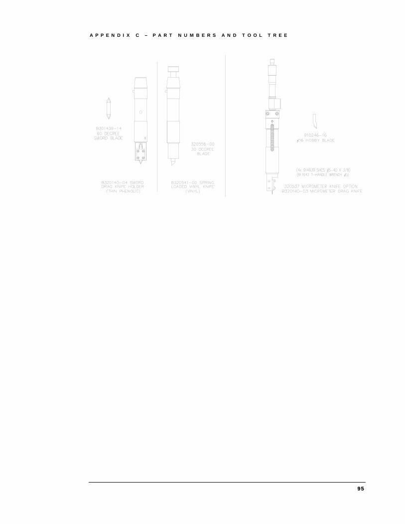
A P P E N D I X C – P A R T N U M B E R S A N D T O O L T R E E
95

A P P E N D I X C – P A R T N U M B E R S A N D T O O L T R E E
p
96

A P P E N D I X D – V A C U U M Z O N E S
97
Appendix D – Vacuum Zones
M 3000 Vacuum Zones
M 1200 Vacuum Zones
Zone 3
Zone 2
Zone 1
Zone 4 Zone 5
Zone 1 Zone 2

C E R T I F I C A T E O F A C C E P T A N C E
M Series Certificate of Installation, Training, and Acceptance Customer: Please complete this document with the installer/trainer and sign the following
page.
Installer/Trainer: Please check off all training items and fax the signed document to Gerber Sales Support at 800-227-6228.
Customer Information Company: Date:
Contact Name: E-mail:
Company Address
Other:
City: State:
Zip Code: Phone:
Product(s) Installed M Series Model: S/N:
Software: S/N:
Other options: Certificate of Installation
Installer Customer Activity
Workstation and PC setup
ART Path and Frontend software installed
M Series configured in ART Path and Frontend
Hand controller operations reviewed
M Series powers on with air switch
Safety light is operational
Vacuum blower is functional
Vacuum zones work as labeled
Shop vac/chip removal system attached and functional
Air supply shows 90psi and meets requirements
Daily maintenance reviewed and performed
Monthly maintenance reviewed
Yearly maintenance reviewed
98

C E R T I F I C A T E O F A C C E P T A N C E
99
Installer Customer Activity
T3 tool head functions with the 5 included tools
Job setup in ART Path reviewed
Router job run (if applicable)
Oscillating knife job run (if applicable)
60 Degree Sward blade job run (if applicable)
Vinyl Spring Knife job run (if applicable)
Creasing wheel job run (if applicable)
We confirm that:
I/We have received the equipment specified previously in good condition and it is now installed and working in a satisfactory manner.
Authorized Signature(s):
Date:
Printed Name(s):
Position:
Installer Signature:
Date:
Printed Name: