m20 user guide - streamhosterweb5.streamhoster.com/hvp/dropros/m20userguide.pdf · mains supply...
TRANSCRIPT

M20 DROOperation and Maintenance Manual
M20 user guide.book Page 1 Monday, April 28, 2008 1:34 PM

i
Con
IntroMainSpecFron
Ke LC
GenSetuEnteSeleSettiSettiSettiSettiSettiSetti
CaMaCa
SettiSettiSaviFactBasiReseSetti
SmAbs/
. . . . . . . . . . . . . . . . . . . . . . . . 3-2
. . . . . . . . . . . . . . . . . . . . . . . . 3-2
. . . . . . . . . . . . . . . . . . . . . . . . 3-3
. . . . . . . . . . . . . . . . . . . . . . . . 3-3
. . . . . . . . . . . . . . . . . . . . . . . . 3-3
. . . . . . . . . . . . . . . . . . . . . . . . 3-3function . . . . . . . . . . . . . . . . . 3-4. . . . . . . . . . . . . . . . . . . . . . . . 3-5. . . . . . . . . . . . . . . . . . . . . . . . 4-1tion . . . . . . . . . . . . . . . . . . . . 4-1tion . . . . . . . . . . . . . . . . . . . . 4-2. . . . . . . . . . . . . . . . . . . . . . . . 4-2sitions . . . . . . . . . . . . . . . . . 4-2
. . . . . . . . . . . . . . . . . . . . . . . . 4-3
. . . . . . . . . . . . . . . . . . . . . . . . 4-4values . . . . . . . . . . . . . . . . . . 4-4ol offset . . . . . . . . . . . . . . . . . 4-4 . . . . . . . . . . . . . . . . . . . . . . . 4-5. . . . . . . . . . . . . . . . . . . . . . . . 4-5des . . . . . . . . . . . . . . . . . . . . 4-5. . . . . . . . . . . . . . . . . . . . . . . . 4-6. . . . . . . . . . . . . . . . . . . . . . . . 5-1irection . . . . . . . . . . . . . . . . . 5-1. . . . . . . . . . . . . . . . . . . . . . . 5-1
. . . . . . . . . . . . . . . . . . . . . . . . 5-1
. . . . . . . . . . . . . . . . . . . . . . . . 5-1
. . . . . . . . . . . . . . . . . . . . . . . . 5-1
M20 user guide.book Page i Monday, April 28, 2008 1:34 PM
tents
duction . . . . . . . . . . . . . . . . . . . . . . . . . . . . . . 1-1 features. . . . . . . . . . . . . . . . . . . . . . . . . . . . . . 1-1ifications . . . . . . . . . . . . . . . . . . . . . . . . . . . . . 1-1t panel . . . . . . . . . . . . . . . . . . . . . . . . . . . . . . . 1-2ys . . . . . . . . . . . . . . . . . . . . . . . . . . . . . . . . . . . 1-2D indications . . . . . . . . . . . . . . . . . . . . . . . . . . 1-3
eral information. . . . . . . . . . . . . . . . . . . . . . . . . 1-3p mode (Engineering mode) . . . . . . . . . . . . . 2-1ring engineering mode . . . . . . . . . . . . . . . . . . . 2-1cting the DRO mode. . . . . . . . . . . . . . . . . . . . . 2-1ng the scale resolution . . . . . . . . . . . . . . . . . . . 2-2ng the display resolution . . . . . . . . . . . . . . . . . 2-2ng the measurement units . . . . . . . . . . . . . . . . 2-2ng the measurement mode . . . . . . . . . . . . . . . 2-2ng the counting direction . . . . . . . . . . . . . . . . . 2-3ng the calibration . . . . . . . . . . . . . . . . . . . . . . . 2-3libration factor . . . . . . . . . . . . . . . . . . . . . . . . . 2-3chine error . . . . . . . . . . . . . . . . . . . . . . . . . . . . 2-3libration process . . . . . . . . . . . . . . . . . . . . . . . 2-3ng the keyboard lock . . . . . . . . . . . . . . . . . . . . 2-4ng the beep status . . . . . . . . . . . . . . . . . . . . . . 2-4ng the changes. . . . . . . . . . . . . . . . . . . . . . . . . 2-4ory default settings . . . . . . . . . . . . . . . . . . . . . . 2-4c functions . . . . . . . . . . . . . . . . . . . . . . . . . . . 3-1t function . . . . . . . . . . . . . . . . . . . . . . . . . . . . . 3-1
ng a value. . . . . . . . . . . . . . . . . . . . . . . . . . . . . 3-1art numeric entry. . . . . . . . . . . . . . . . . . . . . . . 3-1
Inc mode . . . . . . . . . . . . . . . . . . . . . . . . . . . . . 3-1
Rad/Dia mode . . . . . Inch/MM mode. . . . . 1/2 function . . . . . . . Setting the reference
Referencing . . . . . Home function . . . Machine reference
Preset mode . . . . . . Special functions. . Circular bolt hole funcAngular bolt hole funcSDM function. . . . . .
Programming the poRun. . . . . . . . . . . .
Tool offset function . Entering tool offset Implementing the toNotes and cautions
Calculator function. . Display and key moOperation . . . . . . .
Special features. . . Selectable counting dFloating negative signNon-volatile memoryNear zero warning . . Keyboard lock . . . . .

ii
Con
AppPin cRecoInde
M20 user guide.book Page ii Monday, April 28, 2008 1:34 PM
tents
endix 1: Other information . . . . . . . . . . . . . . 6-1onnections. . . . . . . . . . . . . . . . . . . . . . . . . . . . 6-1mmended spares . . . . . . . . . . . . . . . . . . . . . . 6-1x. . . . . . . . . . . . . . . . . . . . . . . . . . . . . . . . . . . . IX-1

1-1
Intr
Introduction
This mthe baall pro
The Mthe sp
You sprodu
MainThe M
• Ze
• Pr
• Ab
• Inc
• Ho
• Ra
• Bo
• An
• 20
• 4 t
• Ca
• Se
• Flo
• No
specifications:
90...265VAC 50...60Hz
T800’ Slow-blow
20 Watts max.
0°C to 45°C
20% to 85% Non-condensing
267mm x 152mm x 82mm (L x H x D)
1kg
M20-TT
9 pin D (F) for transducer
± 100000.00 For 10 Micron Res.
5/10/20/50 Micron
± 7 digit (0.56 inch)
M20 user guide.book Page 1 Monday, April 28, 2008 1:34 PM
oduction
anual explains the operation of the M20 DRO. You should follow sic steps systematically, and take care to ensure that you perform cedures carefully.
20 measures the displacement precisely and accurately. To ensure ecified accuracies, you must install the M20 correctly and precisely.
hould read this manual carefully and thoroughly before using the ct.
features20 has the following features:
ro Reset mode
eset
s/Inc mode
h/mm mode
me Reference
d/Dia mode
lt hole pattern(pcd)
gular bolt hole function
values SDM functions
ool offsets
lculator
lectable counting direction
ating negative sign
n-volatile memory
• Keyboard lock
• Fault signal indication
• Self diagnostic mode
SpecificationsThe M20 has the following
Mains supply
Fuse rating
Power consumption
Operating temperature
Relative humidity
Dimensions
Net weight
Encoder input
Connector types
Maximum count
Resolution
Display

1-2
Intr
FronThe Mkeyboindicaindicais disasegmindicais pos
Keys
ic keys
al point numeric key
firm entry
s the tool offset function
l entry key. Terminates the existing function or
count value as the Machine Reference and s the Home function
s the SDM programming function
s the calculator function
the positive or negative sign when you enter using the keyboard
s the Bolt Hole function
M20 user guide.book Page 2 Monday, April 28, 2008 1:34 PM
oduction
t panel20 DRO has a user friendly keyboard, with positive-touch keys. The ard is a silicon type. The keyboard panel houses the common tions for all axes, namely INCH, MM, ABS, INC. A separate set of tions for diameter mode are provided for each axis (when indication bled it is in radius mode). The display consists of two rows of 7-
ent LED displays. The rows indicate the X and Y axes. The display tes a negative sign when the value is negative and blank if the value itive.
Set the X axis Selects the X axis for the function
Set the Y axis Selects the Y axis for the function
Numer
Decim
To con
Invoke
Cancemode
Storesinvoke
Invoke
Invoke
Selectsvalues
Invoke

1-3
Intr
s what the LEDs mean when they are lit up.
r numeric values.
o confirm your numeric entry and return to the saving the parameters.
your numeric entries and return to the previous the parameters.
meric entry, the [8], [2], [4] and [6] numeric keys , [LEFT] and [RIGHT] arrow keys respectively.
N] arrow keys to move between different fields.
IGHT] arrow keys to toggle the parameters in a
e DRO is counting in inches.
e DRO is counting in millimeters.
e DRO is in Absolute mode, so it is counting vel from the set origin.
e DRO is in Incremental mode, so it is remental travel from the set point.
dicate that the corresponding axis is using ounting.re off, then the corresponding axis is using nting.
M20 user guide.book Page 3 Monday, April 28, 2008 1:34 PM
oduction
LED indicationsThe following table explain
General information• Use the keypad to ente
• Use the [ENTER] key tprevious display while
• Use the [C] key to cleardisplay without saving
• When DRO is not in nuwork as [UP], [DOWN]
• Use the [UP] and [DOW
• Use the [LEFT] and [Rsingle field.
Selects Absolute or Incremental mode
Selects Imperial or Metric mode
Invokes the half function
Invokes the Exit Sleep mode or DRO setting up mode
Numeric 4 / Left Arrow key
Numeric 6 / Right Arrow key
Numeric 8 / Up Arrow key
Numeric 2 / Down Arrow key
INCH Indicates that th
MM Indicates that th
ABS Indicates that ththe absolute tra
INC Indicates that thcounting the inc
DIA These LEDs indiameter (2:1) cIf these LEDs aradius (1:1) cou

1-4
Intr
• Ustim
• In
M20 user guide.book Page 4 Monday, April 28, 2008 1:34 PM
oduction
e the [+/-] key to change the sign of your numeric entry value at any e.
this manual, [name] denotes a dedicated key name.

2-1
Set
Setup mode (Engine
This c
You uspeciworkWe reM20 bThe fofor seactua
Pressthe mmessnorma
EnteTo en
1. T
2. P
In EnparamLock)Softw
The f
"ENT
"LOC
If you
You h
ces, you enter the wrong lock code number the message "INVALID" is displayed in a and you then see the following messages:
y position
lay position
de again.
de incorrectly three times, then the display is.
ode, the display shows "SELECT" on the X-axis.
at you have entered the Engineering mode. es the selection of an axis. There is no need to ode to set another axis.
ou to enter the Engineering mode.
eering mode, the display shows the previously ew parameters using the procedures given in
ering mode to make one particular change e.g. press the [ENTER] key to validate this change.
odeMill and Lathe. functions that are available.
t hole functions.
ool offset functions.
] key has no function, and in Lathe mode the .
M20 user guide.book Page 1 Monday, April 28, 2008 1:34 PM
up mode (Engineering mode)
ering mode)
hapter describes how to setup the M20.
se this mode to set up the M20 to the required needs and fications. You should not use this mode during the normal ing and usage of the M20.commend that you read the complete procedure for setting up the efore you implement the instructions. llowing sections describe each of the parameters and the procedure tting them. In these instructions all the messages in quotes are l displays on the selected axis.
ing the [C] key at any time suspends Engineering mode and shows essage "END". If you press the [C] key again, the DRO shows the age "SELECT". If you press the [ENTER] key, the DRO goes to l counting mode.
ring engineering modeter Engineering mode to setup the parameters for using the DRO:
urn on the DRO.
ress [ON/OFF] > [ABS/INC] > [ON/OFF].
gineering mode only authorized users can set or check the eters. To accomplish this, there is a password facility (Software
. The Software Lock Code has already been set in the DRO are. It is 123.
ollowing messages appear.
ER" at the X-axis display position
” at the Y-axis display position
enter an invalid Lock Code:
ave three chances to enter the correct code.
If during these three chaninitially on the X-axis, thenblinking form for ½ second
"TRY" at the X-axis displa
"AGAIN” at the Y-axis disp
You can then enter the co
If you have entered the coshows "END" on the X-ax
If you enter a valid Lock C
This message indicates thThis message also indicatre-enter the Engineering m
Selecting an axis allows y
When you enter the Enginset parameters. You set nthe following sections.If you have entered Engine"RAD" to "DIA", you must
Selecting the DRO mThe M20 has two modes, Your selection affects the
• Mill mode includes Bol
• Lathe mode includes T
In Mill mode, the [TOOLS[PCD] key has no function

2-2
Set
To se
1. S
2. U
3. P
SettTo se
1. U
2. P
Whilewith w
For eDRO Availa 0.005 0.01 0.02 0.05 Onceautom
rement unitsm. MM indicates metric measurement. This CH indicates imperial measurement. This
nt units:
[RIGHT] arrow keys to highlight the options.
elect the required measurement units.
the measurement units, the DRO remains in this n-line conversion to the other measurement unit M] key is disabled.
on-line conversion to other measurement unit by key is enabled and the DRO can switch between is case, the measurement mode at power on is wer off, e.g. if the DRO is turned off in INCH still be in INCH mode.
rement modeIA. RAD indicates radius measurement. Counts of
adings. Counts are displayed at a ratio of 2:1. oder movement will be shown as 2mm.
M20 user guide.book Page 2 Monday, April 28, 2008 1:34 PM
up mode (Engineering mode)
lect the required mode:
elect [X] or [Y] to select the axis.
se the [LEFT] and [RIGHT] arrow keys to highlight the options.
ress [ENTER] to select Mill or Lathe.
ing the display resolutiont the display resolution:
se the [LEFT] and [RIGHT] arrow keys to highlight the options.
ress [ENTER] to select the required resolution.
the display is showing displacement, you can select the least count hich the display is updated.
xample: If entering 5.456mm at 10 micron resolution, thewill show 5.46
ble Resolutions are: mm 0.0002"mm 0.0005" mm 0.001"mm 0.002"
you have selected the display resolution, the decimal point is set atically.
Setting the measuYou can select inch or mapplies to all the axes. INapplies to all the axes.
To select the measureme
1. Use the [LEFT] and
2. Press [ENTER] to s
Once you have selectedmode permanently and oby pressing the [INCH/M
INCH MM indicates that pressing the [INCH/MM] INCH or MM mode. In thsame as the mode at pomode, at power on it will
Setting the measuYou can select RAD or Ddisplayed 1:1. DIA indicates diameter reFor examle, 1mm of enc

2-3
Set
To se
1. U
2. P
Oncemode
In thispowebe in
SettHere positioption
To se
1. U
2. P
SettThe derror and o
CalibThe Dby a c
After displaDRO scale
e of error or inaccuracy in the machine due to at
on in machine tool structure.
surface is loose.
s cause deflection.
eometry due to temperature gradient.
accuracies in the readings of the DRO even DRO counter are accurate. Also, this error is of the machine travel.
linear error in the DRO by multiplying the actual n error correction factor.
the existing Calibration Factor, calibrating the tomatically and stores the new value.ey when the DRO shows the message
at a datum point.
alibrated by pressing the [X], or [Y] key.
other end of slip gauge or measuring standard. actual reading on the display.
RIGHT] arrow key. '. Enter the slip gauge value in Microns.
ey. d.
M20 user guide.book Page 3 Monday, April 28, 2008 1:34 PM
up mode (Engineering mode)
lect the measurement units:
se the [LEFT] and [RIGHT] arrow keys to highlight the options.
ress [ENTER] to select the required measurement units.
you have selected the measurement mode, the DRO remains in this permanently.
case measurement mode at power on is same as the mode at r off, e.g. if the DRO is turned off in DIA mode, at power on it will still DIA mode. This mode is selected in Engineering mode only.
ing the counting directionyou select which direction of the slider movement will count as ve linear displacement. You can toggle between the left and right s by pressing [LEFT] and [RIGHT] arrow keys.
lect the counting direction:
se the [LEFT] and [RIGHT] arrow keys to highlight the options.
ress [ENTER] to select the required counting direction.
ing the calibrationistance traveled by an encoder may differ from the actual travel. This can occur due to machine wear and tear, misalignment of the scale, ther factors. This error can be linear or non-linear.
ration factor (Linear Error Compensation)RO is calibrated for both, resolution of the encoder and machine error ommon factor called the calibration factor.
traveling a known distance using a slip gauge, the DRO should y the value equal to length of slip gauge. The value counted by the may differ from the actual distance if the DRO is not calibrated for resolution and machine error.
Machine errorThere may be some degreleast one of the following:
• Gravity causes deflecti
• The fit between mating
• Driving or cutting force
• Distortion of machine g
These errors can cause inthough the scales and thedifferent in different parts
You can compensate for aDRO actual readings by a
Calibration processThere is no need to deleteDRO counter does that au1. Press the [ENTER] k
"DISPVAL".
2. Position the machine
3. Zero the axis being c
4. Move machine to theTake no notice of the
5. Press the [LEFT] or [The display shows '0
6. Press the [ENTER] k“CALFAC" is displaye

2-4
Set
7. Wd
You carrow[ENTE
You mare foshoulreads
SettDurincurrenkeybo
LOC entry
LOC entry
You caxes You cin En
To se
1. U
2. P
tusis mode, then the Beep at keyboard entry is
his mode, then the Beep at keyboard entry is
ns by pressing the [LEFT] or [RIGHT] arrow key
RIGHT] arrow keys to highlight the options.
lect whether the beep is on or off.
n you change any single field, then when the ears, you need to press the [ENTER] key, to ently, otherwise the changes will be not be
ingswing factory default settings for the currently the [ENTER] key when the "RST DFT"
Calib
Default Setting
MILL5 micron (0.0002")
M20 user guide.book Page 4 Monday, April 28, 2008 1:34 PM
up mode (Engineering mode)
hen you press the [ENTER] key again, the Calibration Factor is isplayed. It is:
an edit the Calibration Factor by pressing the [LEFT] and [RIGHT] keys. You can edit it up to 6 digit decimal places. If you press the R] key, then you can bypass the editing stage.
ay need to edit the Calibration Factor to fine tune it, if small errors und during production. If the counter display reads longer than it d, then you should reduce the value of the Calibration Factor. If it shorter then increase the value.
ing the keyboard lockg machining, if you accidently reset any one of the axes, then the t work piece may be damage. To avoid this, you can use the ard lock facility. There are two possible options:
ON: If you select this mode in Engineering mode, then keyboard is disabled.
OFF: If you select this mode in Engineering mode, then keyboard is enabled.
annot lock the keyboard for a single axis. Locking means that all the are locked simultaneously.an toggle these options by pressing the [LEFT] or [RIGHT] arrow key gineering mode.
t the keyboard lock:
se the [LEFT] and [RIGHT] arrow keys to highlight the options.
ress [ENTER] to select whether the keyboard lock is on or off.
Setting the beep staBEEP ON: If you select thenabled.
BEEP OFF: If you select tdisabled.
You can toggle these optioin Engineering mode.
To set the beep status:
1. Use the [LEFT] and [
2. Press [ENTER] to se
Saving the changesIn Engineering mode, whe"SAV CHG" message appsave the changes permanapplied.
Factory default settYou can revert to the folloselected axis, by pressingmessage appears.
ration Factor (microns/pulse) = Length of Slip gauge in micronsValue counted by DRO
Parameter
DRO typeDisplay Resolution

2-5
Set
When[ENTE
Mea
Mea
Cou
Cali
Key
Bee
Par
M20 user guide.book Page 5 Monday, April 28, 2008 1:34 PM
up mode (Engineering mode)
you have set all the paramters in Engineering mode, press the R] key.
surement Unit Inch / MM
surement Mode Rad
nting Direction Left
bration Factor 1.0
board Lock OFF
p ON
ameter Default Setting
3-1
Bas
Basic functions
This c
ResDurin datumany dwork a corn
To red
1. S
2. B
3. ETp
When
0.000
0.000
SettYou uaxis incente
To se
1. B
2. S
3. E
wn for this position and a new origin is also set.
osition deletes the existing origin. o for all axes sets the new origin at the current
e decimal point key you cannot enter an integer
int depends upon the setting you selected for rameter in Engineering mode.
Display Resolution to 1.0 in Engineering mode, 5678, the integral part changes to 5678000. ou do not press the decimal point key and you , say 9, the display changes to 6789000. If you
ys, then the display keeps rolling over until you the decimal point key.
al point key, you can edit the fractional part of l value this is also a rolling type entry until you
re the reference is taken from a common point e.
Here the reference is taken the first time that ey.
key. e is set to zero.
al reference (datum) of the DRO.
M20 user guide.book Page 1 Monday, April 28, 2008 1:34 PM
ic functions
hapter describes the M20’s basic functions.
et functiong machining and setting operations, you often need to establish a
to a particular point. With this feature you can redefine your origin at esirable location. For example, to reference all relevant points on a piece from a particular point such as the center of the work piece or er of the work piece.
efine your datum:
elect the axis that you want to reset.
ring the tool to the reference point.
nter 0.000 to reset the axis. his point is then used as the reference origin for all the relevant oints on the work piece.
the axis (X or Y) is in Linear mode, the display becomes:
(in MM mode)
0 (in Inch mode)
ing a valuese this feature to set any value (within range) to any position on the Absolute mode. For example, to set a particular value to a corner or
r of the work piece.
t a value:
ring the tool to desired point.
elect the X or Y axis.
nter the value and press the [ENTER] key.
This new value is now sho
Setting a new value to a pSetting a new value to zerposition.Once you have pressed thvalue.
Smart numeric entryThe position of decimal pothe Display Resolution pa
For example, if you set thethen if you enter the valueHowever, if after 4 digits ypress another numeric keykeep pressing numeric kepress the [ENTER] key or
When you press the decimthe value. Like the integrapress the [ENTER] key.
Abs/Inc modeABS is Absolute mode. Hewhen measuring a distanc
INC is Incremental mode. you press the [ABS/INC] k
1. Power on the DRO.
2. Press the [ABS/INC]The Incremental valu
This is now the increment

3-2
Bas
If youINC] new i
If in Inany acase zero.
The fThe inthe D
RadYou umeaslathe
You smodevaluegiven
The dDRO distanthe di
nvert a display value from metric to imperial ggles between the two modes for all the axes
sponding LED indication is given near the front e, the decimal point is moved one position to the feature to avoid complicated calculation of setting and machining operations.
press the [INCH/MM] key.
en the two options if you selected Inch MM for mode. Otherwise it remains as either Inch or
de (MM LED is lit), with the display showing e [INCH/MM] key, the display changes to alent measurement in inches.The Inch LED is
M20 user guide.book Page 2 Monday, April 28, 2008 1:34 PM
ic functions
reset the Absolute value, then the first time that you press the [ABS/key after the reset, the incremental value is reset. This is now the ncremental reference of the DRO.
cremental mode, you want to reset the incremental reference, for xis you can press the particular axis key in Incremental mode. In this the Absolute value remains unaltered and the incremental value is
eature toggles all the axes simultaneously.cremental reference is a temporary reference. When you power off
RO, this reference becomes zero.
/Dia modese this feature to display the measurement value in the required urement mode, i.e. Radius or Diameter. It is particularly useful for cross axis.
elect the required mode in the engineering parameter setting. In this you can toggle the display between unit value display and double display for the selected axis. A corresponding LED indication is near the front panel display for the respective axis.
iagram below shows a cylindrical work piece with centre C. If the is reset at C and T indicates the tool position, then A is the displayed ce in Radial mode. In Diametric mode, with the same tool position splayed distance would be equal to B which is twice that of A.
Inch/MM modeYou use this function to counits of measurement. It tosimultaneously. The correpanel display. In Inch modleft.You can also use this conversion of units during
To change between units,
You can only toggle betwethe X axis in Engineering mm.
Example:
If the counter is in MM mo25.400, when you press th1.0000, which is the equivthen lit.

3-3
Bas
1/2 fYou ucan u
1. PY
2. StT
Execu
Sett
RefeThe Drestorhave the Drefere
With tpredecalledtransdslide.enabland M
In thesense
In theprede
se the ABS pulse. All relevant points on work from this ABS pulse position.
pulses) are located throughout the length of u can always select any one ABS pulse as the
ction sets the display to 0.000 on encountering you can permanently set a point on the machine is useful in batch production.
ABS/Reference pulse in both the directions. racies, you must ensure that you only
the same ABS/Reference mark on the ensed the first time because the job dimensions k.
tion
.
xis. elected axis starts blinking.
or an "ABS" pulse input from the transducer.
r) slide to sense the ABS pulse. ensed.
al counting mode with the zero position set at
M20 user guide.book Page 3 Monday, April 28, 2008 1:34 PM
ic functions
unctionse this function to directly halve the current value on the axis. You se this function to find the centre of the job.
ress the [1/2] key. ou are prompted by the message “SELECT".
elect the desired axis whose value needs to be halved by pressing he [X] or [Y] key on the front panel. he value displayed on the desired axis is halved.
ting the 1/2 function in absolute mode alters the datum of the axis.
ing the reference
rencingRO has a built in feature to save the last reading at power off and e the same reading at power on. It is possible that the travel may moved while DRO is powered off. Hence the last reading stored by RO may not indicate the true position, so you need to nce the DRO to the Datum.
he M20 you can set a reference for machining or settings at fined locations on a selected axis. These predefined points are ABS references or pulses and they are marked on the scale or ucer. They are encountered by the DRO when it moves along the
However, this can only be used when the referencing function is ed. There are two methods for referencing: Home Function mode achine Reference mode.
Home Function mode, the display is set to 0.000 when the DRO s the first Reference/ABS pulse.
Machine Reference mode, you can set the display to any fined value after the DRO senses the first Reference/ABS pulse.
You move the slide to senpiece are then referenced
Home functionThe reference marks (ABSthe scale or transducer. Yoreference. The Home Funthe first ABS pulse. Thus, table to be the origin. This
The DRO can sense the However, for repeat accusense it in one.You should always sense transducer that the DRO sare referenced to this mar
Setting the Home Func
1. Press the [REF] key
2. Select “HOME”.
3. Select the required aThe last digit on the sThe DRO is waiting f
4. Move the (transduceThe "ABS" pulse is s
The DRO changes to normthe ABS position.

3-4
Bas
MachThis fReferzero, as the
The MHomeshow
If the point settin
1. Ma
2. Em
3. A
4. MTnT
5. N(
y saved the machine reference figure and the axis, i.e. A, is marked as the Job Zero, A
erence
eference value on the axis as and when ob Zero.
achine reference function and move the slide
ensed at B, the DRO restarts counting from the lue stored earlier with sign reverse (i.e. -
istance of the Home Zero from the Job Zero.
n on page 3-4, if the slide is moved to A, then ro as desired, as A is the Job Zero.
ABS/Reference pulse in both the directions. racies, you must ensure that you only
the same ABS/Reference mark on the ensed the first time because the job dimensions k.
erence value
C REF” > “SET MC”.
you want to store the value for the Machine
nd the current value becomes zero, as this is .
M20 user guide.book Page 4 Monday, April 28, 2008 1:34 PM
ic functions
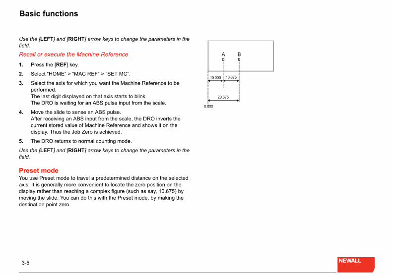
ine reference functionunction is analogous to the Home function, except that at the ence Mark on the transducer, the Home function sets the display to while Machine Reference function inserts the value that you saved Machine Reference.
achine Reference value is the distance of thet Job Zero from the Zero (i.e. the ABS mark on the transducer). The following diagram
s how to find and store the Machine Reference.
tool is at position C, then A-D is the job length and B is the nearest outside the job at which transducer gives an ABS pulse. In this case, g the machine reference makes the count zero at A.
ove the slide (i.e. the tool) near to position A; preferably between A nd B.
xecute the Home function (see Home function on page 3-3) and ove the slide towards B, as indicated by the arrow.
s the ABS pulse is encountered at B, the display shows zero.
ove the slide to A. he displayed value is the distance between the job edge and its earest ABS pulse. At A, the counter shows a value (say 11.875). his is the machine reference value.
ow follow the procedure for storing the Machine Reference value see Setting the machine reference value on page 3-4).
You have now successfullcurrent tool position of thebecomes the new origin.
Setting the machine ref
You can set the Machine Rrequired, to establish the J
1. Execute the setting mtowards B.
2. As the ABS pulse is smachine reference va11.875). This is the d
3. In the example showthe display shows ze
The DRO can sense the However, for repeat accusense it in one.
You should always sense transducer that the DRO sare referenced to this mar
Setting the machine ref
1. Press the [REF] key.
2. Select “HOME” > “MA
3. Select the axis whereReference.
4. Enter 0.000. The value is stored, athe Job Zero position
Job zero
3-5
Bas
Use tfield.
Reca
1. P
2. S
3. SpTT
4. MAcd
5. T
Use tfield.
PresYou uaxis. displamovindestin
M20 user guide.book Page 5 Monday, April 28, 2008 1:34 PM
ic functions
he [LEFT] and [RIGHT] arrow keys to change the parameters in the
ll or execute the Machine Reference
ress the [REF] key.
elect “HOME” > “MAC REF” > “SET MC”.
elect the axis for which you want the Machine Reference to be erformed. he last digit displayed on that axis starts to blink. he DRO is waiting for an ABS pulse input from the scale.
ove the slide to sense an ABS pulse. fter receiving an ABS input from the scale, the DRO inverts the urrent stored value of Machine Reference and shows it on the isplay. Thus the Job Zero is achieved.
he DRO returns to normal counting mode.
he [LEFT] and [RIGHT] arrow keys to change the parameters in the
et modese Preset mode to travel a predetermined distance on the selected It is generally more convenient to locate the zero position on the y rather than reaching a complex figure (such as say, 10.675) by g the slide. You can do this with the Preset mode, by making the ation point zero.

4-1
Spe
Special functions
This c
CircYou uperimcircledrill. Thole. the hoDRO
Param
In thethe Xright, axis,
ter than 10 for the number of holes, then the n. You must then press the [C] key.re equally spaced on the circle.
ey.
te for the centre of the circle.
te for the centre of the circle.
e circle.
le for the first hole.
holes (maximum 10).
e x and y coordinates of each hole location around o advance through each hole loaction. Press [C] .
ENT
ENT
Rad
Ang
Hole
M20 user guide.book Page 1 Monday, April 28, 2008 1:34 PM
cial functions
hapter describes the M20’s special functions.
ular bolt hole functionse this function to create a table of coordinates of holes on the eter of a circle. You enter the geometrical data from the drawing: centre coordinates, starting angle, radius and number of holes to he DRO automatically generates the required coordinates for each
The DRO shows the distance between the current tool position and le. To achieve the desired hole position, move the travel so that the
down counts to zero.
eters to be entered for a bolt hole:
following diagram, for the circle on the left the starting hole lies on axis, so you must enter the angle as 0.000. For the circle on the the desired holes are shifted by same angle with respect to the X so you must enter the the offset angle, α.
If you enter a number greamessage “invalid" is showIt is assumed that holes aTo set up a bolt hole:
1. Press the [PCD] key.
2. Select “B HOLE”.
3. Press the [ENTER] k
4. Enter the X coordina
5. Enter the Y coordina
6. Enter the radius of th
7. Enter the starting ang
8. Enter the number of
The readout will display ththe circle. Press ENTER tto exit the bolt hole routine
CNT 0 X coordinate of the centre.
CNT 1 Y coordinates of the centre.
ius Radius of the circle.
le Starting angle for first hole.
s No. of holes. max 10

4-2
Spe
AngYou ui.e. pafrom radiusrequirthe cumove
If youmessIt is aTo se
1. P
2. S
3. P
4. E
5. E
6. E
7. E
8. E
9. E
As thethat this com
You ccount
ly applicable for mass production. In this rdinates of different tool positions on machine y. You can then recall these stored coordinates f job.
itionsich you can program the SDM values: Program
y enter the coordinates of the position using the RO is in ABS mode, then the value that you Absolute value from the zero position. If the value that you enter is considered as an the previous SDM value.
ey.
r.
for that point.
row key to go to the next step.
for that point.
until you have entered all the SDM values.
M20 user guide.book Page 2 Monday, April 28, 2008 1:34 PM
cial functions
ular bolt hole functionse this function to create a table of coordinates of holes on an arc, rt of a circle rather than a full circle. You enter the geometrical data
the drawing: circle centre coordinates, starting angle, ending angle, and number of holes to drill. The DRO automatically generates the ed coordinates for each hole. The DRO shows the distance between rrent tool position and the hole. To achieve the desired hole position, the slide so that the DRO down counts to zero.
enter a number greater than 10 for the number of holes, then the age “invalid" is shown. You must then press the [C] key.ssumed that holes are equally spaced on the circle.t up an angular bolt hole:
ress the [PCD] key.
elect ““ARC”.
ress the [ENTER] key.
nter the X coordinate for the centre of the circle.
nter the Y coordinate for the centre of the circle.
nter the radius of the circle.
nter the starting angle for the first hole.
nter the ending angle for the last hole.
nter the number of holes (maximum 10).
machine works the holes the display shows the number of the hole e machine is drilling and the distance to the next hole. When the job plete, the display shows the coordinates of the first hole.
an press the [C] key at any time to bring the DRO back to normal ing mode.
SDM functionThe SDM function is mainfunction, you store the coopermanently in the memorfor doing the same type o
Programming the posThere are two ways by whand Learn.
Program
In this mode, you manuallnumeric keyboard. If the Denter is considered as an DRO is in INC mode, the incremental distance from
To program SDM values:
1. Press the [SDM] key.
2. Select ‘PROGRAM’.
3. Press the [ENTER] k
4. Enter the step numbe
5. Enter the coordinates
6. Press the [RIGHT] ar
7. Enter the coordinates
8. Repeat steps 6 and 7

4-3
Spe
Exam
The f
In thewould
You c
the numeric keypad for programming the SDM t tool position is considered as the SDM value. s for large programs.
as Program mode, you program the points as
es at point A.
t B.
mode is ON.
00
ey to store the value.
t C.
00
ey to store the value.
SDM values in this way.
recall the stored SDM values to run the same
no.1. e distance from the current tool position to the
SD
No.
1
2
3
4
5
6
M20 user guide.book Page 3 Monday, April 28, 2008 1:34 PM
cial functions
ple
ollowing diagram shows an example.
above diagram A, B, C, D, E and F are the points to be drilled. You program these as follows:
an program up to 20 SDM values in this way.
Learn
In this mode you don’t usevalues. Instead the currenThis mode is advantageou
Using the same example follows:
1. Reset the X and Y ax
2. Bring the tool to poin
3. Ensure that AbsoluteThe display shows: X: 10.000 Y: 10.0
4. Press the [ENTER] k
5. Bring the tool to poinThe display shows: X: 10.000 Y: 30.0
6. Press the [ENTER] k
You can program up to 20
RunYou use the Run option totype of Job.
Example
1. Press the [SDM] key.
2. Select ‘RUN’.
3. Press 1 to recall SDMThe display shows th
M NO. ABS Programming INC Programming
Name X Y X Y
A ABS 0.000 ABS 0.000 ABS 0.000 ABS 0.000
B ABS 10.000 ABS 10.000 INC 10.000 INC 10.000
C ABS 10.000 ABS 30.000 INC 0.000 INC 20.000
D ABS 25.000 ABS 25.000 INC 15.000 INC - 5.000
E ABS 40.000 ABS 30.000 INC 15.000 INC 5.000
F ABS 40.000 ABS 10.000 INC 0.000 INC -20.000

4-4
Spe
pd
4. MT
You c
You mand rHome
You cSDM If youthe m
ToolAn ex
Point showthe sa
t tool. With the tool offset function you can make values when the cutting edges of different tools work piece.
luesnction for both axes and establish the Home
ace A of the job.
function and enter the value for the X axis le shown above).
eturn to Normal counting mode.
ace B of the job.
function and enter the required value for the Y mple shown above).
nce from step 2 for all tools and enter the
l offsetO calculates the actual offsets for different
s the reading as (-15, -5). The desired reading
l offset values are:
M20 user guide.book Page 4 Monday, April 28, 2008 1:34 PM
cial functions
rogrammed SDM position. The second decimal point at the seventh igit indicates that the DRO is in Preset mode.
ove the tool to make displays zero. he tool has reached the position of SDM 1.
an recall all the SDMs using this procedure.
ust ensure that the zero position for all the axes, while programming ecalling is the same. We recommend that the zero position is the Zero position, since it is easily found.
an program a maximum of 20 SDM values.no.1 is always absolute. enter an SDM step number greater than 20, then the display shows essage "invalid". You must press the [C] key to clear this.
offset functionample of this function is shown in the following diagram.
P is the Home Zero position on the machine. At point Q, tool no.1 s readings as (-15, -5). At the same point Q, tool no.2 does not show me reading because of the offset of the cutting edge of the second
tool with respect to the firsthe DRO display the sametouch the same point on a
Entering tool offset va1. Execute the Home fu
Zero position.
2. Touch the tool to surf
3. Select the tool offset (10.000 in the examp
4. Press the [C] key to r
5. Touch the tool to surf
6. Select the tool offset axis (5.000 in the exa
7. Press the [C] key.
You can repeat the sequerequired values.
Implementing the tooUsing the example, the DRtools as follows:
At point Q, the DRO showat point Q is (10, 5).
This means that the actua
X: 10 - (-15) = 25
Y: 5 - (-5) = 10
Counting directions
Tool
ChuckJob/Object
Surface A
Surface B
Home Zero

4-5
Spe
At povalueoffset
The Dabove
To im
1. PT
2. U
3. E
4. P
You c
NoteYou mand im
The vFor thdesire0).
You cthe myou aarrow
You mCAL.F
rform the following calculator operations. This rm simple on-line calculations while machining.
smber that you entered and the calculated result.
lect the mathematical function to be performed.
calculate the result of the current sum.
an entered number back to '0' if you have not
[0…9] to enter values.
plemented. is yet to be implemented.
M20 user guide.book Page 5 Monday, April 28, 2008 1:34 PM
cial functions
int R the normal DRO reading is (-25, -10), but because of the offset s, the DRO shows it as (0, 0) once you have implemented the tool .
RO calculates the actual offset values for all tools, as described .
plement the tool offset:
ress the [TOOLS] key. he display shows the current reading plus the actual tool offset.
se the [UP] and [DOWN] arrow keys to find the tool that you want.
nter the tool number that you want to implement.
ress the [ENTER] key.
an press the [C] key at any time to return to normal counting mode.
s and cautionsust ensure that the Home Zero position is the same, while editing plementing.
alues that you can enter are dependent on the counting direction. e shown example, if the counting directions are reversed, the d value at point Q must be entered as (-10, -5), to make point R (0,
an program up to 4 tools. If you enter a tool no. greater than 4 then essage "invalid" is shown. You must press the [C] key to clear this. If re scrolling through the tool numbers with the [LEFT] and [RIGHT] keys, then after 4 the number rolls back to 1.
ust ensure that parameters such as RAD/DIA, INCH/MM and AC are the same, while programming and recalling.
Calculator functionYou use this feature to pemeans that you can perfo
• Add
• Subtract
• Multiply
• Divide
• Sine
• Cosine
• Tangent
• Sine Inverse
• Cosine Inverse
• Tangent Inverse
Display and key modeThe X axis displays the nu
The Y axis is where you se
Press the [ENTER] key to
Press the [C] key to deletepressed the [Y] axis key.
You use the number keys
The [+/-] key is yet to be imThe [.] (decimal point) key

4-6
Spe
OperThe bThe Xhave in the
1. TTT
2. Yntd
3. WT
4. Tt
Whendisplacurren5. Y
E
6. Yot
7. IY
You c
43.5 - 10.2 = 33.3:
y to enter the calculation function.
[.] [5].
y until ‘Sub’ appears on the display.
[.] [2].
ey to complete the calculation. n the X axis window.
y to exit the calculator function.
e [ENTER] key and the calculation result is al options available:
to exit calculator mode.
ar the X axis display to '0' to start a new tor mode had just been entered.
the start of a new calculation. When you enter cally clears the existing calculation result and ar in the X axis window. The Y axis window is
d in the X axis window, you can press the Y thematical function. Here the value in the X axis us calculation is used as the first number in the
(43.5 - 10.2) x 9 = 299.7.
y to enter the calculation function.
[.] [5].
M20 user guide.book Page 6 Monday, April 28, 2008 1:34 PM
cial functions
ationasic operation is the same as a typical simple personal calculator. axis represents the display of the calculator. As the DRO does not keys available for the mathematical operators these are expressed Y axis window.
o enter calculator mode press the [CALC] key. he X axis shows '0'. he Y axis is blank (no display).
ou can enter a number using the [0…9]. [+/-] and [.] keys. This umber is shown on the X-axis. If you make a mistake, you can press
he [C] key to delete the entered numbers one at a time. When you elete the last entered number ithe X axis shows '0'.
hen you have entered the number, press the [Y] axis key. he Y axis legend shows 'Add'.
o select a different mathematical function press the [Y] axis key until he required option is displayed.
you press the [Y] key the result of the current calculation is yed in the X-axis. Thus if no sum has yet been performed the t entered number is displayed.ou can now enter the next number. ntering this number changes the X axis display.
ou can now either press [ENTER] to complete your mathematical peration (See Example 1) or press the [Y] axis key again and keep
he mathematical operations going (See Example 2).
f you press [ENTER], the X axis shows the calculation result and the axis is blank.
an press the [CALC] key at any time to exit the calculator function.
Example 1
To perform the calculation
1. Press the [CALC] ke
2. Press the keys [4] [3]
3. Press the [Y] axis ke
4. Press the keys [1] [0]
5. Press the [ENTER] kThe result is shown i
6. Press the [CALC] ke
Once you have pressed thdisplayed you have sever
• Press the [CALC] key
• Press the [C] key to clecalculation as if calcula
• Enter a new number asthe number it automatithe new numbers appeblank.
• With the result displayeaxis key to select a mawindow from the previonew calculation.
Example 2
To perform the calculation
1. Press the [CALC] ke
2. Press the keys [4] [3]

4-7
Spe
3. P
4. P
5. PTw
6. P
7. P
8. PT
9. P
M20 user guide.book Page 7 Monday, April 28, 2008 1:34 PM
cial functions
ress the [Y] axis key until ‘Sub’ appears on the display.
ress the keys [1] [0] [.] [2].
ress the [Y] axis key. his completes the calculationa dn the result is shown in the X axis indow.
ress the [Y] axis key until ‘Multi’ appears on the display.
ress the [9] key.
ress the [ENTER] key to complete the calculation. he result is shown in the X axis window.
ress the [CALC] key to exit the calculator function.

5-1
Special features
Special features
This chapter describes the M20’s special features.
Selectable counting directionThis feature allows counting in either the left or right direction. See Setting the counting direction on page 2-3 for further details.
Floating negative signIn cases where the current tool position is negative, the negative sign is shown by the first digit of the value. As the value increases the negative sign moves to the next digit. This feature improves the readability of the display as compared to having the negative sign at the last digit.
Non-volatile memory This memory is used to store 20 SDM values, 4 tool offsets, the settings of the DRO and the machine reference values.
Keyboard lockDuring machining, if you accidently reset any one of the axes, then the current work piece may be damage. To avoid this, you can use the keyboard lock facility. See Setting the keyboard lock on page 2-4 for further details.
M20 user guide.book Page 1 Monday, April 28, 2008 1:34 PM

6-1
Appendix 1: Other information
Appendix 1: Other information
This appendix gives some further information that you may find useful when using the M20.
Pin connectionsPin connection details for 9-pin ‘D’ (F) type connector.
Pin connections
Connector Signal
For line receiver TTL interface (optional)
1 Phase RM
2 Phase RM
3 VCC (+5)
4 Shield
5 Gnd (0V)
6 Phase A
7 Phase A
8 Phase B
9 Phase B
Connector Signal
M20 user guide.book Page 1 Monday, April 28, 2008 1:34 PM
IX-1
Index
Index
AABS pulse 3-3ABS reference 3-3Absolute mode 1-3
CCalibration factor 2-4Connector types 1-1
DDimensions 1-1Display 1-1
FFuse rating 1-1
HHome zero 3-4, 4-4, 4-5
IIncremental mode 1-3Invalid Lock Code 2-1
JJob zero 3-4, 3-5
MMains supply 1-1Maximum count 1-1
OOperating temperature 1-1
PPower consumption 1-1
QQuantization error 1-1
RRelative humidity 1-1Resolution 1-1
SSDM learn mode 4-3SDM program mode 4-2SDM run 4-3Software lock 2-1
TTransducer input 1-1
VValid Lock Code 2-1
WWeight 1-1
M20 user guide.book Page 1 Monday, April 28, 2008 1:34 PM

HEAD OFFICENewall Measurement Systems Ltd.
Custom Sensors & TechnologiesTechnology Gateway, Cornwall Road
South WigstonLeicester LE18 4XH
United KingdomTelephone: +44 (0)116 264 2730Facsimile: +44 (0)116 264 2731
Email: [email protected]
Newall Electronics, Inc.Custom Sensors & Technologies
1778 Dividend DriveColumbus, OH 43228
USATelephone: +1 614.771.0213
Toll Free: 800.229.4376Facsimile: +1 614.771.0219Email: [email protected]
Web: www.newall.com
023 80500-UK/1 Rev NEI
M20 user guide.book Page 1 Monday, April 28, 2008 1:34 PM