m3express: a low-cost independently-mobile reconfigurable
TRANSCRIPT

M3Express: A Low-Cost Independently-MobileReconfigurable Modular Robot
Kevin C. Wolfe, Matthew S. Moses, Michael D.M. Kutzer, and Gregory S. Chirikjian
Abstract— This paper presents M3Express (Modular-Mobile-Multirobot), a new design for a low-cost modular robot.The robot is self-mobile, with three independently driven wheelsthat also serve as connectors. The new connectors can beautomatically operated, and are based on stationary magnetscoupled to mechanically actuated ferromagnetic yoke pieces.Extensive use is made of plastic castings, laser cut plastic sheets,and low-cost motors and electronic components. Modules inter-face with a host PC via Bluetoothr radio. An off-board camera,along with a set of modules and a control PC form a convenient,low-cost system for rapidly developing and testing controlalgorithms for modular reconfigurable robots. Experimentalresults demonstrate mechanical docking, connector strength,and accuracy of dead reckoning locomotion.
Index Terms— modular robots, self-reconfigurable systems,mechanism design for low-cost mobile robots
I. INTRODUCTION
Modular reconfigurable robots (MRRs) continue to expe-rience remarkable development. Since the initial work in the1990’s [1]–[4], individual modules have become more capa-ble, and increasing numbers of functional modules are beingincorporated into working demonstrations [5]–[8]. However,the cost and complexity of most modular robot systems tendsto increase almost as rapidly as their capabilities. Somecounter-examples to the trend of increasing unit complex-ity include efforts in programmable matter [9] and swarmrobotics [10]. However, in programmable matter the self-mobility of modules is not a central focus, and most (low-cost) swarm systems lack mechanical interconnectability.
The MRR presented here is intended as a low-costtestbed for real-world docking and reconfiguration algo-rithms; for demonstrations with large numbers of self-mobile,automatically-docking modules; and for classroom use inundergraduate engineering programs. A number of MRRprojects have produced low-cost robots designed for edu-cation and broader public use. The most well-established of
This research was partially supported under an appointment to the De-partment of Homeland Security (DHS) Scholarship and Fellowship Program,administered by the Oak Ridge Institute for Science and Education (ORISE)through an interagency agreement between the U.S. Department of Energy(DOE) and DHS. ORISE is managed by Oak Ridge Associated Universities(ORAU) under DOE contract number DE-AC05-06OR23100.
This work was also supported in part by NSF grant IIS-0915542 RI:Small: Robotic Inspection, Diagnosis, and Repair.
K. Wolfe, M. Moses, M. Kutzer, and G. Chirikjian are with theDepartment of Mechanical Engineering, Johns Hopkins University, Balti-more, Maryland. {kevin.wolfe, matt.moses, mkutzer1,gregc}@jhu.edu
M. Moses and M. Kutzer are also with the Research and ExploratoryDevelopment Department, Johns Hopkins University Applied Physics Lab-oratory, Laurel, Maryland.
Fig. 1. Modules are independently mobile. Wheels function as intercon-nectors.
Fig. 2. Module geometry allows formation of complex chain and latticestructures. Here modules are shown in a triangular-prism lattice.
these is the open-source Molecubes project [11]. While madeof components with relatively high availability, this designstill relies on expensive components such as thin-section ballbearings and electrical slip-rings. Other examples of systemsdesigned specifically for low cost and high availability are[12] and [13]. In all three of these cases, modules have asingle degree of freedom and docking must be accomplishedmanually. In contrast, the new low-cost module presentedin this paper has three independent degrees of freedom andthree active mechanical connectors.
The robot presented here is morphologically similar toM3, the design initially presented in [14]. As in [14], themodules have three dual-purpose wheels which serve asdriving wheels and mechanical inter-connectors (see Fig. 1).In some heterogeneous MRRs, special-purpose modulesequipped with wheels are used to allow high mobility [15]or to quickly transport non-mobile modules [16]. A self-mobile module with four degrees-of-freedom and severalnew mobility modes was recently presented in [17], howeverthis system does not currently have automatic connectionability. The M3 is a homogeneous system with wheels andconnectors combined into one dual-purpose mechanism. Itis important to note that, the M3 connectors will only matewhen aligned in a discrete set of offset angles, which creates
2012 IEEE International Conference on Robotics and AutomationRiverCentre, Saint Paul, Minnesota, USAMay 14-18, 2012
978-1-4673-1405-3/12/$31.00 ©2012 IEEE 2704
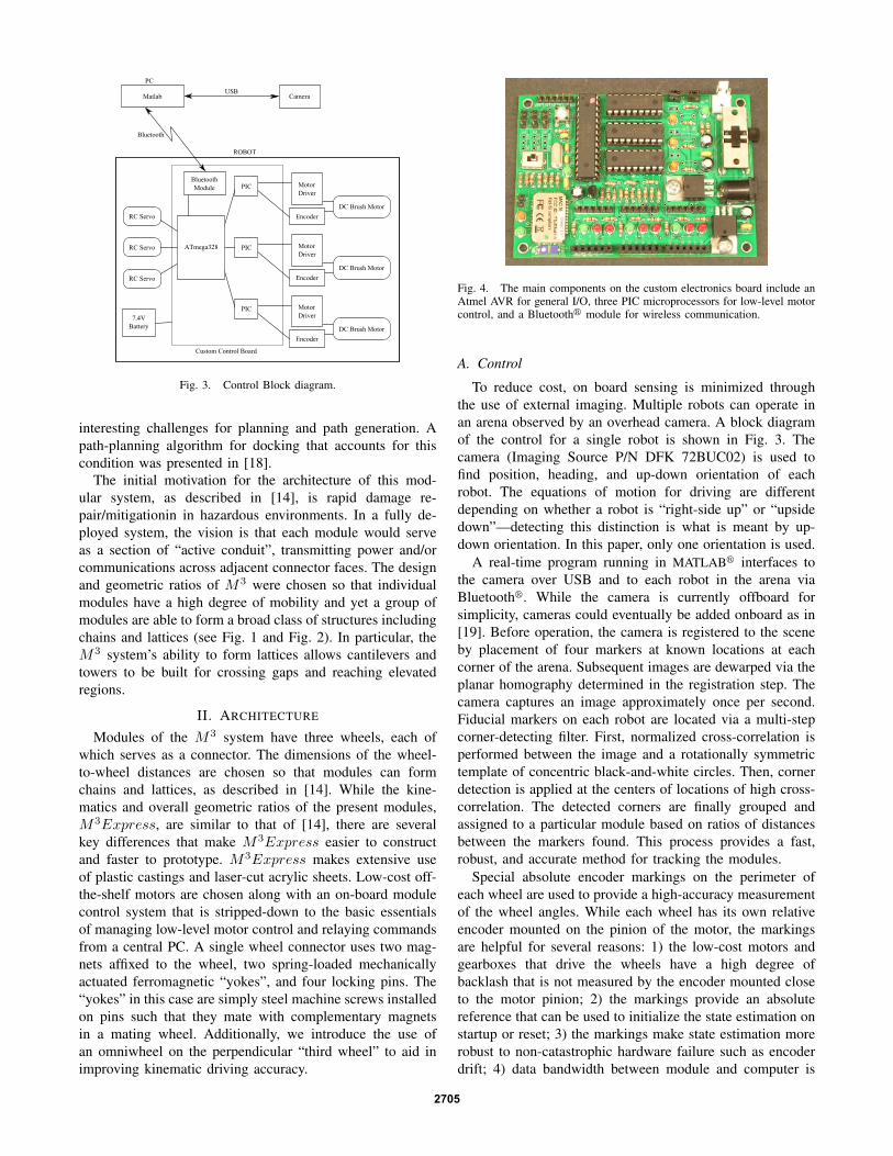
Fig. 3. Control Block diagram.
interesting challenges for planning and path generation. Apath-planning algorithm for docking that accounts for thiscondition was presented in [18].
The initial motivation for the architecture of this mod-ular system, as described in [14], is rapid damage re-pair/mitigationin in hazardous environments. In a fully de-ployed system, the vision is that each module would serveas a section of “active conduit”, transmitting power and/orcommunications across adjacent connector faces. The designand geometric ratios of M3 were chosen so that individualmodules have a high degree of mobility and yet a group ofmodules are able to form a broad class of structures includingchains and lattices (see Fig. 1 and Fig. 2). In particular, theM3 system’s ability to form lattices allows cantilevers andtowers to be built for crossing gaps and reaching elevatedregions.
II. ARCHITECTURE
Modules of the M3 system have three wheels, each ofwhich serves as a connector. The dimensions of the wheel-to-wheel distances are chosen so that modules can formchains and lattices, as described in [14]. While the kine-matics and overall geometric ratios of the present modules,M3Express, are similar to that of [14], there are severalkey differences that make M3Express easier to constructand faster to prototype. M3Express makes extensive useof plastic castings and laser-cut acrylic sheets. Low-cost off-the-shelf motors are chosen along with an on-board modulecontrol system that is stripped-down to the basic essentialsof managing low-level motor control and relaying commandsfrom a central PC. A single wheel connector uses two mag-nets affixed to the wheel, two spring-loaded mechanicallyactuated ferromagnetic “yokes”, and four locking pins. The“yokes” in this case are simply steel machine screws installedon pins such that they mate with complementary magnetsin a mating wheel. Additionally, we introduce the use ofan omniwheel on the perpendicular “third wheel” to aid inimproving kinematic driving accuracy.
Fig. 4. The main components on the custom electronics board include anAtmel AVR for general I/O, three PIC microprocessors for low-level motorcontrol, and a Bluetoothr module for wireless communication.
A. Control
To reduce cost, on board sensing is minimized throughthe use of external imaging. Multiple robots can operate inan arena observed by an overhead camera. A block diagramof the control for a single robot is shown in Fig. 3. Thecamera (Imaging Source P/N DFK 72BUC02) is used tofind position, heading, and up-down orientation of eachrobot. The equations of motion for driving are differentdepending on whether a robot is “right-side up” or “upsidedown”—detecting this distinction is what is meant by up-down orientation. In this paper, only one orientation is used.
A real-time program running in MATLABr interfaces tothe camera over USB and to each robot in the arena viaBluetoothr. While the camera is currently offboard forsimplicity, cameras could eventually be added onboard as in[19]. Before operation, the camera is registered to the sceneby placement of four markers at known locations at eachcorner of the arena. Subsequent images are dewarped via theplanar homography determined in the registration step. Thecamera captures an image approximately once per second.Fiducial markers on each robot are located via a multi-stepcorner-detecting filter. First, normalized cross-correlation isperformed between the image and a rotationally symmetrictemplate of concentric black-and-white circles. Then, cornerdetection is applied at the centers of locations of high cross-correlation. The detected corners are finally grouped andassigned to a particular module based on ratios of distancesbetween the markers found. This process provides a fast,robust, and accurate method for tracking the modules.
Special absolute encoder markings on the perimeter ofeach wheel are used to provide a high-accuracy measurementof the wheel angles. While each wheel has its own relativeencoder mounted on the pinion of the motor, the markingsare helpful for several reasons: 1) the low-cost motors andgearboxes that drive the wheels have a high degree ofbacklash that is not measured by the encoder mounted closeto the motor pinion; 2) the markings provide an absolutereference that can be used to initialize the state estimation onstartup or reset; 3) the markings make state estimation morerobust to non-catastrophic hardware failure such as encoderdrift; 4) data bandwidth between module and computer is
2705

Fig. 5. Modules are built of low-cost easily available motors, and quicklyfabricated plastic components.
reduced as position, orientation, and wheel angles can all besimultaneously captured by the camera.
Once the configuration is obtained, a planning routinedetermines the motion commands to send to the robot. Astring of serial commands is sent over Bluetoothr, andthe serial commands are received and processed by theonboard processor. The processor is an Atmel ATmega328running Arduino firmware [20]. Serial commands are parsed,and then motion commands are sent to three PIC18F1320mircoprocessors with a Step/Direction interface. Each PICperforms closed loop position and/or speed control on themotors, counts encoder pulses, and outputs a PWM signal tothe motor driver. The motor drivers (Solarbotics P/N 51510)are installed aftermarket on the off-the-shelf DC motors. TheArduino can report a status packet back to the PC, howeverthis is currently not used.
B. Construction
The module has a plastic laser cut chassis that holdsthree brushed DC motors (Solarbotics P/N GM17) and threeminiature RC servo motors (see Fig. 6). To these motorsand servos, the wheels and docking mechanisms are attachedusing mounting brackets (see Fig. 7). The wheels, dockingmechanisms, motor mounts and servo mounts are made ofpolyurethane that was cast in silicone molds. Masters forthese molds were created using a 3D printer. The reusablesilicone molds allow parts to be produced quickly andeconomically with little post-processing. The two primarydrive wheels are fitted with large diameter rubber o-ringswhich act as tires. The third perpendicular wheel is fittedwith a custom omni-directional wheel (omniwheel) whoseconstruction is described in Section II-D. In addition tomechanical components, a custom electronics board and7.4 V lithium polymer battery pack are attached to the frame.Lastly, fiducial markers are applied to the module to allowfor tracking using an overhead camera.
(a) Chassis with motors, servos, and wheels.
(b) Module with electronics.
Fig. 6. Above is an overview of how the module is constructed.
C. Interconnect Mechanism
The interconnect mechanism is similar to the spring-loaded magnet system presented in [21]. The interconnectin [21] is actuated by shape-memory alloy, while our mech-anism is actuated by a miniature RC servo driving a slidingwedge mechanism (see Fig. 7). The sliding wedge mecha-nism functions as a mechanical slip ring. A section view oftwo mating connectors is shown in Fig. 8. The connectorsare genderless, but they must be offset by 90◦ or 270◦ inorder to mate. In each wheel, two magnets are staticallymounted. A smaller sliding disk carries two steel screwsand four tapered pins, all of which insert through holes inthe wheel. Springs between the wheel and sliding disk pushthem apart. The springs are strong enough to overcome themagnetic attraction force when two wheels are mated. Themotor-driven wedge overcomes the spring force to push thesliding disk outward and engage the connectors. This designallows strong magnetic attraction to be turned on and off bya small motor. In addition, the servo motor only operateswhen the connector is changing state and does not need torun continuously.
In contrast to most other MRR designs, our system cur-rently does not have a means for hard-wired intermodulecommunication (although the Bluetoothr radios can be usedfor wireless linking). There is ample space on the wheelwhere off-the-shelf spring-loaded electrical contacts could beinstalled, but the cabling to these contacts would either limitthe free rotation of the wheel or necessitate an electrical slipring. While slip rings are often used in MRRs [11], [14], theyare not the best choice in a design focused, high availability,ease of manufacturing, and low-cost parts.
2706

Fig. 7. The mechanical interconnection mechanism is driven by a slidingwedge connected to a miniature RC servo.
Fig. 8. Section view of two mating wheels (top). View of the wheel face(bottom). Dashed arrows indicate motion of the components for connectionand disconnection.
A design for an optical communication port allowingfor free rotation of the wheel is shown in Fig. 9. A ring-shaped diffuser made of translucent plastic is embedded inthe perimeter of each wheel. This forms a diffuse windowthat allows visibility of an emitter and detector mounted stat-ically to the robot chassis. When two robots are mated, thearrangement provides a half-duplex communication channel.
Fig. 9. Conceptual design showing a mating pair of optical interconnects.An emitter/detector pair is mounted statically to the frame and a ring-shapeddiffuser is embedded in each wheel.
During transmission, light from the emitter on one robot willilluminate the entire diffuser ring. This light can then bepicked up by the detector on the other robot, independentof wheel rotation angle. Multiple emitters can be used ifstronger illumination is needed. This design should providea low-cost non-contact high bandwidth serial communicationchannel for each mated connector; implementation is an areafor future work.
D. Omni-directional Wheel (Omniwheel)
As discussed in [14] and [18], the “third wheel” of therobot is mounted orthogonally to the driving wheels so thatmultiple robots can form complex three-dimensional struc-tures. However, the design and weighting of each modulestill allows it drive in plane as a differential-drive robot (alsocommonly known as the classic kinematic cart). The additionof the third wheel does cause some issues; the frictionexperienced by the perpendicular wheel increases slippingand scuffing of the two drive wheels. While the originalsystem in [14] did not explicitly address this issue, twoproposed strategies for reducing this friction were consideredfor M3Express: the addition of ball casters near the thirdwheel to lift it off the ground, and the use of an omniwheel.After testing both approaches, the omniwheel was chosen.This choice was made because it allowed a module to trackthe kinematic model presented in Section III much moreaccurately, especially during commonly used trajectories—straight driving and pivots. During straight-ahead travel, theomniwheel is very effective at reducing the frictional dragexperienced. However, during pivots, the omniwheel is usedto effectively increase the traction of the module.
The omniwheel is constructed by adding a ring of rollersto the perimeter of the existing third wheel. The rollers aremade of hobby beads with “tires” made of heatshrink tubing.Roller axles are made of stiff steel wire. The rollers and axlesare then sandwiched between three layers of 1.5 mm lasercutplastic, which is then mounted to the wheel casting.
III. KINEMATICS AND CONTROLLABILTY
As previously described, the modules can be driven andsteered like a differential-drive robot. However for two mod-ules to dock, the position and orientation of the modules mustbe compatible, along with the orientation of their adjacent
2707

(a) (b)
(c) (d)
Fig. 10. The omniwheel is built of a ring of rollers, with roller axlescaptured by three laser-cut disks.
wheels. Thus, in addition to x, y, and θ, the angles of thewheels (i.e., φC , φL, and φP ) are also considered. Whenthe pose (x, y, θ) of a single module is defined as shown inFig. 11, the kinematic equations of motion are given by
x(t) = G
(φCφL
)(1)
for
x(t) =
xy
θ
φCφL
and G =r
2
− sin(θ) sin(θ)cos(θ) − cos(θ)− 2W − 2
W2r 00 2
r
where φC and φL are driving wheel velocities defined asshown in Fig. 11. This model assumes a no-slip conditionfor the two drive wheels.
The friction experienced by the third perpendicular wheelcan cause this assumption to be violated. As described inSection II-D, we added an omniwheel to this third wheelto help the module track (1) more accurately. The velocityof the omniwheel is determined using a slip-minimizingcondition for the third wheel [14], [18]. As a function ofthe velocities of the two drive wheels, this slip-minimizingconstraint is given as
φP =−Lrθ
=L
W
(φC + φL
)= 2
(φC + φL
). (2)
When considering control strategies for docking twomodules, it is important to note that the system in (1) isnot controllable due to a holonomic constraint between θ,φC , and φL. However, if we consider a system xC(t) =(x, y, θ, φC)
T it can be shown that the new system issmall-time locally controllable. This can be demonstrated byperforming two Lie bracket operations as defined in [22].
Fig. 11. (Left) The pose of a module can be represented using x, y, andθ as shown. (Right) Relevant module dimensions for kinematic driving andreference directions for rotation of each of the three wheels. The center ofmass is also shown.
Letting r =W = 1, we can relate g1 and g2 to the columnsof G such that
xC(t) = g1φC + g2φL
where
g1 =
− sin(θ)
2cos(θ)
2−11
and g2 =
sin(θ)
2
− cos(θ)2
−10
.
It can then be shown that
[g1,g2] =
− cos(θ)− sin(θ)
00
and
[g1, [g1,g2]] =
− sin(θ)cos(θ)
00
.
It is clear that these four vectors are linearly independent andthus the reduced system is small-time locally controllable.This can be similarly shown for a reduced system of x, y,θ, and φL.
Note that, if we look at a system of x, y, θ, and φPwith respect to (1) and (2), this system is not controllable.However, since the perpendicular wheel is intended to slipto some degree, this can be overcome for docking by inten-tionally slipping this wheel once the proper pose is realized.This strategy has proven to be successful in experimentaltesting.
IV. PERFORMANCE
A testbed system was implemented, including a fully-functional robot, a lightweight non-functional dummymodule, an overhead camera with associated PC, andMATLABr control software. Some simple docking tests wereperformed and various robot capabilities were measured.
2708

Fig. 12. Sequence proceeds left to right, top to bottom. A fully-functionalmodule approaches a dummy docking target, connects, and then lifts thenewly connected dummy module.
TABLE ICOSTS AND MASSES FOR A SINGLE M3Express MODULE
Item Cost Masspolyurethane castings $4 344 glasercut acrylic components $18 152 g3× DC gearmotors $17 105 g3× DC motor drivers/encoders $30 15 g3× RC servos $12 32 gmain circuit board $73 57 gLiPo battery (7.4 V 1500 mAH) $21 66 g6× magnets $6 18 gcables and hardware $9 89 gTotal $190 878 g
A. Cost
One goal of this design was to make a module that wasinexpensive, so that modules could be produced in significantnumbers. Table I provides an overview of the cost associatedwith a single module. Cost estimates for many modularrobots are not widely published; however, several low-costsystems do exist including GZ-I (an updated version of Y1with a cost less than $280) [13], DoF-Box ($120) [12], andMolecubes ($242 without electronics) [11]. With a total costof around $190 per module, the new M3Express moduleis of similar expense to those reported previously. This costestimate does not include labor. Still, given the design andfabrication techniques utilized, small batch production shouldallow modules to be produced at a rate of approximately oneper three to four hours. Its cost is also less than one tenththe cost of the original M3 module presented in [14].
B. Weight and Torque
Each module has a mass of 878 g. Table I provides abreakdown of masses of various components. The center-of-mass of the module was found by measuring the wheelweight distribution, and is shown in Fig. 11. This, combinedwith the weight of the module, determines the requiredtorque for a module to lift itself out of plane along its longaxis (similar to what is shown in Fig. 12). This torque wascalculated to be 0.63 N·m. However, the motors produce aneffective stall torque of 0.32 N·m at the wheel face. Thus, at
present the module is unable to lift itself or another module.Strategies for overcoming this are discussed in Section V.
C. Docking Experiments
The docking mechanism was tested by manually aligninga lightweight (494 g) non-functional module near a fully-functional module. The functional module was then remotelycommanded to drive next to the target, extend its pin plate,and lift the dummy module. This process was remotelycontrolled by a human operator sending commands via theMATLABr interface. Successful docking and lifting wasachieved, showing that the docking mechanism works asdesigned and the docking process is viable. Fig. 12 presents asequence of images captured by the overhead camera duringthe test.
In addition to testing whether the docking mechanism wasable to connect two modules, the strength of the connectionwas tested. When axially loaded at the center of the twodocked wheels, the docking mechanisms provide a holdingforce of 11 N (the module itself weighs 8.6 N). When theaxial load is applied at the rim of the wheel, the holding forceis reduced to 4.8–5.5 N and is dependent on the exact locationof loading. In shear, the holding force is much higher; it iseffectively limited by the shear strength of the locking pins.
D. Driving, Slip, and Scuffing
The module, as currently configured in software, has amaximum driving speed of 3.1 cm/s. The speed of the modulewas capped to help prevent slip of the drive wheels. Despiteattempts to minimize slip (e.g., increasing tire friction andintroduction of the omniwheel), the module experiences anontrivial amount of slip. This slip and scuffing lead to devi-ation from the expected kinematic driving behavior describedin Section III and [18]. Fig. 13 shows the superposition ofthe final module locations from 25 trials of commanding therobot to drive forward 500 mm in an open-loop fashion. Theresults indicate that, for trajectories of significant length, aclosed-loop control law will need to be coupled with theresults from [18] to achieve repeatable docking of moduleswith arbitrary initial positioning.
V. CONCLUSIONS AND FUTURE WORK
A new “Express” design for the modules of the M3 systemwas designed and prototyped. The module was designed tobe easily assembled, and incorporates primarily off-the-shelfor easy to manufacture components, making it low-cost. Thedesign and architecture produce a modular system that ispotentially useful for educational outreach and/or use in anundergraduate setting. While the modules do not perform aswell as those described in [14], they are useful for rapidlytesting real-world control algorithms on a group of severalrobots at less that one tenth the cost. For example, sincethe modules are independently mobile and able to dockwith one another in the plane, reconfiguration strategies canbe investigated for three-dimensional structures that can be“unfolded” and initially formed in the plane such as the trussin Fig. 2.
2709

Fig. 13. Fiducial locations from ten trials of running the robot straight ahead from a known initial starting place. A closeup of error in final location isshown on the left, while absolute position is shown to scale on the right.
During testing, several things were discovered that can beimproved. The module cannot lift itself or additional dockedmodules. There are several ways to address this issue: 1) theweight of the robot can be reduced by adding lightweightfiller material to the polyurethane castings, 2) unnecessarymaterial can be removed from the laser-cut parts, and 3) theoverall size of the module can be reduced. Improving theoutput torque can be achieved by: 1) selecting new motors,2) reducing friction in the drivetrain, and 3) applying a highervoltage across the motors through the use of a second 11.1 Vlithium polymer battery pack. Another future improvementcould include the creation of a single molded frame thatwould incorporate the servo and motor mounts. This wouldalso make the module cheaper and easier to manufacture.
Future goals include building and testing additionalmodules, developing closed-loop control strategies for au-tonomous docking of modules, and investigating planningmethods for 3D docking and assembly.
REFERENCES
[1] T. Fukuda and S. Nakagawa, “Approach to the dynamically reconfig-urable robotic system,” Journal of Intelligent & Robotic Systems,vol. 1, pp. 55–72, 1988.
[2] S. Murata, H. Kurokawa, and S. Kokaji, “Self-assembling machine,”in Proceedings of the IEEE International Conference on Robotics andAutomation, 1994, pp. 441–448.
[3] M. Yim, “Locomotion with a unit-modular reconfigurable robot,”Stanford University, Tech. Rep., 1994.
[4] G. Chirikjian, “Kinematics of a metamorphic robotic system,” inRobotics and Automation, 1994. Proceedings., 1994 IEEE Interna-tional Conference on, May 1994, pp. 449 –455 vol.1.
[5] K. Stoy, R. Nagpal, and W.-M. Shen, Eds., Modular Robots: The Stateof the Art, Proceedings of the IEEE 2010 International Conference onRobotics and Automation Workshop. IEEE, 2010.
[6] M. Yim, W.-M. Shen, B. Salemi, D. Rus, M. Moll, H. Lipson,E. Klavins, and G. Chirikjian, “Modular self-reconfigurable robot sys-tems [Grand Challenges of Robotics],” IEEE Robotics & AutomationMagazine, vol. 14, no. 1, pp. 43–52, Mar. 2007.
[7] S. Murata and H. Kurokawa, “Self-reconfigurable robots: Shape-changing cellular robots can exceed conventional robot flexibility,”IEEE Robotics & Automation Magazine, pp. 71–78, Mar. 2007.
[8] R. Groß, M. Bonani, F. Mondada, and M. Dorigo, “Autonomous self-assembly in swarm-bots,” IEEE Trans. Robotics, vol. 22, no. 6, pp.1115–1130, Dec. 2006.
[9] K. Gilpin, A. Knaian, and D. Rus, “Robot pebbles: One centime-ter modules for programmable matter through self-disassembly,” inRobotics and Automation (ICRA), 2010 IEEE International Conferenceon, May 2010, pp. 2485 –2492.
[10] M. Rubenstein and R. Nagpal, “Kilobot: A robotic module fordemonstrating behaviors in a large scale (210 units) collective,” inProceedings of the IEEE 2010 Int. Conf. on Robotics and Automationworkshop “Modular Robots: The State of the Art”, 2010, pp. 53–57.
[11] V. Zykov, A. Chan, and H. Lipson, “Molecubes: An open-sourcemodular robotics kit,” in IROS-2007 Self-Reconfigurable RoboticsWorkshop, 2007. [Online]. Available: http://www.molecubes.org/
[12] D. Daidie, O. Barbey, A. Guignard, D. Roussy, F. Guenter, A. Ijspeert,and A. Billard, “The DoF-box project: An educational kit forconfigurable robots,” in Advanced Intelligent Mechatronics, 2007IEEE/ASME International Conference on, September 2007, pp. 1–6.
[13] H. Zhang, J. Gonzalez-Gomez, Z. Xie, S. Cheng, and J. Zhang,“Development of a low-cost flexible modular robot GZ-I,” in Proceed-ings of the 2008 IEEE/ASME International Conference on AdvancedIntelligent Mechatronics, 2008.
[14] M. D. M. Kutzer, M. S. Moses, C. Y. Brown, D. H. Scheidt, G. S.Chirikjian, and M. Armand, “Design of a new independently-mobilereconfigurable modular robot,” in Proc. IEEE International Conf. onRobotics and Automation, May 2010.
[15] F. Hou, N. Ranasinghe, B. Salemi, and W.-M. Shen, “Wheeledlocomotion for payload carrying with modular robot,” in IntelligentRobots and Systems, 2008. (IROS 2008). 2008 IEEE/RSJ InternationalConference on, Sept. 2008, pp. 1331–1337.
[16] S. Kernbach, O. Scholz, K. Harada, S. Popesku, J. Liedke, H. Raja,W. Liu, F. Caparrelli, J. Jemai, J. Havlik, E. Meister, and P. Levi,“Multi-robot organisms: State of the art,” in ICRA 2010 Workshop -Modular Robotics: State of the Art, 2010.
[17] G. Ryland and H. Cheng, “Design of iMobot, an intelligent re-configurable mobile robot with novel locomotion,” in Robotics andAutomation (ICRA), 2010 IEEE International Conference on, May2010, pp. 60 –65.
[18] K. C. Wolfe, M. D. Kutzer, M. Armand, and G. S. Chirikjian,“Trajectory generation and steering optimization for self-assemblyof a modular robotic system,” in Proc. IEEE International Conf. onRobotics and Automation, May 2010.
[19] B. Shirmohammadi, M. Yim, J. Sastra, M. Park, and C. Taylor,“Using smart cameras to localize self-assembling modular robots,”in Distributed Smart Cameras, 2007. ICDSC ’07. First ACM/IEEEInternational Conference on, Sep 2007, pp. 76 –80.
[20] “Arduino - homepage,” http://arduino.cc/.[21] S. Murata, E. Yoshida, K. Tomita, H. Kurokawa, A. Kamimura, and
S. Kokaji, “Hardware design of modular robotic system,” in Proceed-ings of the 2000 IEEE/RSJ International Conference on IntelligentRobots and Systems, 2000, pp. 2210–2217.
[22] R. M. Murray, Z. Li, and S. S. Sastry, A Mathematical Introductionto Robotic Manipulation. CRC Press, 1994.
2710