maahslcarbon-carbon composites carbon-carbon composites · 2013-08-30 · carbon-carbon (c-c)...
TRANSCRIPT

MaahslCarbon-Carbon Composites
Carbon-Carbon Composites: Emerging Materials for Hypersonic Flight ="
An emerging class of high-temperature materials called carbon-carbon G_
composites are being developed to help inake advanced aerospace flight become __
a reality. _ . "
Conceivelof a sleek, futuristically shaped aerospace vehicle racing
throug_the #tm_here at many times the speed of sound. Molecules of air
contil_uouslybjalabard the skin of the vehicle, driving its temperature up.
Temperature_reach 2000oF, 2500OF, 3000oF, and even higher depending on thelocation on/the vehicle.
An ae}'_space engineer engaged in designing such a vehicle would discover
that light, eight materials capable of exte@ded service at these extreme
temper_ttUres are simply not available. Ho_ever, an emerging class of
materials called carbon-carbon composite S are presently under development tofilY this need. Participating signific_antly in this development are the
N_¢ion_l Aeronautics and Space Administration (NASA) and the Department otDefense.
in comparison with other materials, carbon-carbon (C-C) composites are
relative newcomers, having been discovered by accident in the late 1950's.
Singe then, these materials have been developed and improved, and are
currently used in a variety of qpecialty applicatlons which include friction
applications as aircraft brake._iscs, propulsion applications as rocket nozzlethroats and exit cones, and m_litary applications as missile nose tips.
Possibly the best known use,of carbon-carbon composites is on Space Shuttle
where it is used to protec_ the nose cap and leading edges of the wings from
the searing heat of entry from space into the earth's atmosphere. In this
role, they prevent the _xtreme heat generated during re-entry Irom reaching
the _ain metallic strud_ure of the Shuttle."Because of the high, temperature strength and low density of carbon-carbon
composites, aerospace engineers would like to use these materials in even more
advanced applications. One application of considerable interest is _s the
structure of the aerospace vehicle itself rather than simply as a protective
heat shield as on Space Shuttle. But suitable forms of these materials have
yet to be developed. If this development can be successfully accomplished,advanced aerospace vehicles such a_ the National hero-Space Plane (NASP) andother hypersonic vehicles will be closer to becoming a reality.
_.?
),
What Are Carbon-Carbon Composites?
Carbon-carbon (C-C) composites constitute a special subclass of compositematerials. In simple terms, a composite is a material that contains both a
ceinforcing material to provide strength and stiffness, and a matrix material,
or "glue", to surround and hold the reinforcement in place. Many types el
composites exist; one eve,'yday example is reinforced concrete in which steelrods constitute the reinforcement and the concrete is the "glue".
Somewhat more sophisticated composites are the familiar fiberqlaz_s
https://ntrs.nasa.gov/search.jsp?R=19900016764 2020-04-07T06:40:20+00:00Z

Maahs/Carbon-Carbon Composites
composites used for fishing poles and other sporting goods, as wel] as
automobile bodies and boat hulls and interiors. The reinforcing material in
fiberglass composites is the glass fibers and the matrix material is a
plastic. Carbon-carbon composites are those special composites in which both
the reinforcing fibers and the matrix material are essentially pure carbon.
Fabrication
Fabricating C-C composites is time consuming and expensive. May_y steps
are required and commercial production times range from three to nine months,
sometimes longer for material requiring special processing. Costs can run
from a low of about $100/pound to well over $5000/pound depending on the size
and complexity of the parts involved and the amount of processing required.
To fabricate a C-C part, one starts by first fabricating a carbon-resin
part. Generally, the resin used is a phenolic resin, the same resin used in
laminating plywood. Layers of carbon cloth coated with the uncured resin are_tacked and formed into the desired shape using special fixtures to maintain
its shape. Then the part is cured by heating in a pressurized oven, or
autoclave, to temperatures near 325OF.
Following curing, the carbon-resin part is placed in a furnace and heatedto _ te_._erature near 1500OF to decompose the resin, leaving the carbon cloth
bound loosely in a residue of carbon char. This resin decomposition processJ_ ca]l_)d "c_:bonization". To prevent the part from burning up, the air in
the furnace is replaced with an inert gas, typically nitrogen. For some
applications, the part may be heat treated to higher temperatures, sometimes
as high as 450OOF.
Aithoagh at this point in the fabrication process one has a true C-C part
for the first time, the part is of little use as a structural material
because the matrix o[ carbon char is porous and weak. Additional processing,
called densJfication, is required to fill these pores and increase strength.
Resin infiltration and carbonization, and chemical vapor deposition are the
two basic methods employed.In the resin-infiltration method, the part is immersed in liquid phenolic
r_In and pressure is applied to force the resin into its pores. The part isthen removed from the resin, wiped clean, and cured in an oven. Then follows
another carbonization. This cycle of impregnation, cure, and carbonization is
typically repeated three or more times until the desired properties are
obtained. Sometimes petroleum or coal tar pitch is used for densification in
place of the phenolic resin.
In the chemical-vapor-deposition method, the porous part is heated in a
r_ctor Lc sear 2000OF in the presence of a hydrocarbon gas such as methane.
The methai1e gas enters the pores and decomposes on contacting the hot part,
depo,_iting carbon within the pores. Several days to several weeks may be
required to complete this process.
_g,_rdless of which of the two densification methods are employed, the
cari Jn rei,.forcing fibers ultimately become bound within a matrix of
essentially pure carbon and the desired strength is achieved.
If oxidation protection is required for the intended end application,
addltional processing is necessary; otherwise, the part is ready to enter_ervice at this point.

Naahs/Carbon-Carbon Composites
The Challenge of Oxidation Protection
Carbon burns, i.e., oxidizes, readily i_ air at high temperatures. Coal
is one common form of carbon, and coal is known to be a good fuel. Carbon-
carbon composites will similarly oxidize in high-temperature air unless they
are adequately protected. Thus, the challenge facing materials scientistsamounts to this: how can one prevent this material, which is a good fuel,
from burning in high-temperature air? Because C-C composites offer such
outstanding advantages as high-temperature structure--advantages that are notavailable in other materials--the challenge has been accepted.
Oxidation Protection Concepts
Materials scientists are exploring various approaches for achieving the
necessary oxidation protection. Research is intensive, and, although manyvariations exist, most oxidation-protection concepts include certain basic
features. In most concepts, the first li,e of defense consists of an
oxidation-resistant coating. This coating is typically a layer of silicon
carbide about 0.01 inches thick. Silicon carbide is particularly useful
because it forms an extremely thin layer of protective silica glass when
exposed to high-temperature air. This thin layer blocks further oxygen attack
of the silicon carbide coating, and the coating, in turn, encapsulates and
protects the C-C structure.Unfortunately, all is not this simple. Both the s_licon carbide coating
and the C-C structure being protected expand and contract with changes in
temperature during service. Since the extent of this expansion andcontraction is not the same for these two materials, many fine cracks form in
the coating. Oxygen can enter through these cracks and attack the C-C
structure.
To prevent this attack, a second line of defense is employed. Thisdefense consists of glazes applied to the surface of the coated part and
glassy sealants within the pores of the C-C structure. The purpose of the
glazes is to fill the cracks in the coating and, hence, block access of oxygento the C-C stzucture, while the purpose of the glassy pore sealants is to coat
the interior surfaces of the pores and prevent direct contact of oxygen with
the carbon.
Still, alt is not resolved. Carbon begins to oxidize at a siqnificant
rate at temperatures as low as lO00°l", and glazes and sea!antr which areeffective over the broad temperature range encountered in flight have not yet
been developed. Hence, a third line of defense is 1_eeded. This third line oIdefense consists oI various additives distributed wlt_,in the carbon matrix.
The purpose of these additives is twolold: consume iny oxyqen reachinq the C-C structure, and form additional quantities o[ protective qlasses within the
pores. Unfortunately, these additives arc activated by oxidation and duringthis activation some matrix carbon im also oxidized with a resulting loss of
mechanical properties of the C-C part.Occasionally a fo,lrth line of defense is employed. _Jxidation-resistant
coatings may be applied to the reinforcin.j fibers themselves, or additives mayeven be distributed within them. These approaches are highly experimental.
Were it not for the [act that the first line of defense, the silicon

MaahslCarbon-CarbonComposites
carbide coating, developed cracks, none of the additional defenses would be
needed. Therefore, materials scientists are trying to reduce or eliminate
coating cracks by formulating coatings of different compositio, and by
employing transition layers between the coating and the C-C core. To date,
no approach has been fully successful.Many variations of the above schemes have been explored. The basic goal
remains the same, however: to develop adequate oxidation protect'on in high-
temperature air without compromising the desirable mechanical properties of
the C-C structure being protected.
Space Shuttle
On Space Shuttle, an oxidation-resistant carbon-carbon (ORCC) composite
is used to protect the nose cap and the leading edges of the wings from
temperatures as high as 2500°F as the Shuttle reenters the earth's atmosphere
from orbit. The ORCC material is bolted to the vehicle main structure_
standing off in [rout of it to protect it from the extreme heat of reentry.This ORCC material, designed to be serviceable for up to 100 missions, has
performed well and in accord with expectations. This material is the onlyreusable ORCC composite in service today.
Advanced Hypersonic Vehicles
Since ORCC composites have done an outstanding job on the Space Shuttle,
aerospace engineers would like to employ them in even more demanding
applications. On Space Shuttle, the ORCC composite does not form part of thevehicle structure, but serves as a heat shield only. However, if both the
vehicle structure and the heat shield could be integrated together with one
single material serving both functions, one could realize a substantialsavings in weight. Such an integrated system is referred to as "hot
structure". Plans for advanced hypersonic vehicles depend on the availability
of a suitable hot structure. Presently, ORCC composites are the main
candidates for this purpose, but no suitable advanced forms of ORCC
composites are yet available.Requirements for hot structure are more demanding than for a heat shield
material. It is clearly not practical to replace main vehicle structure
periodically the way one could replace a much smaller, removable heat shield.
Hence, design engineers demand longer life capability from a hot structure
component than the 100 missions for Space Shuttle ORCC parts. Also, skin
temperatures predicted for advanced hypersonic vehicles are considerably
higher than for Space Shuttle, approaching 3000°F, and possibly higher.
Increased strength is also needed if ORCC composites are to serve as efficient
primary structure.What alternatives are there to employing ORCC composites for hot
structure? If more conventional materials had to be depended on, design
engineers would have to employ some method of cooling to maintain the
structure at temperatures low enough to enable their use. But such cooling
systems are complex and heavy. For example, heat exchangers, pumps, and a
myriad of fine cooling passages would be required. Estimates of the weightassociated with cooled metal structur_ range from 4 to iI times the weight for

MaahslCarbon-Carbon Composites 5
carbon-carbon composites. Such heavy cooling systems would seriously
compromise vehicle performance and even prevent certain performance objectivesfrom being met.
There is no question that the problems faced in developing advanced forms
of structural ORCC composites are great. But the potential payoffs also are
great. In fact, some consider ORCC composites to be essential to the
successful development of the U.S.'s best known proposed advanced aerospace
vehicle, NASP.
Other Applications
As mentioned briefly earlier, C-C composites are currently used in
various applications. Mostly, these are specialty applications related to the
aircraft, military, or aerospace arenas where the performance available onlyfrom C-C composites is the primary consideration rather than cost.
One example of an application of quite a different nature exploits thefact that carbon is a material that is highly compatible with human tissue.
Because of this compatibility and the high strength and low weight of C-C
composites, interest is growing to use these composites as artificial bone
implants.The largest commercidl market for unprotected C-C composites is aircraft
brakes. In these applications, C-C composites are used as the friction discs
in the brake system. Weight savings compared with steel can be substantial,
as high as 60 percent. Because brake temperatures on typical landings are
below 900OF, oxidation is not a serious issue and lifetimes of 3000 landings
are possible.
Military and aerospace applications are far more demanding. Typical
applications include missile nose tips and rocket nozzle throats and exitcones. Service life in these single-use applications is short--minutes to a
few hours--and unprotected C-C is employed. Although the C-C component erodes
during service, this erosion is accounted for in the design of the component,
ensuring that the mission is completed before all the material is consumed.Oxidation-resistant carbon-carbon composites are le_s mature materials but
they offer significant performance payoffs for manned, reusable aerospacevehicles. Applications, already discussed, include the thermal protection
material for NASA's Space Shuttle and airframe structure for advanced
hypersonic vehicles. Other applications where reusability and lonq life are
required incl_de turbine engine rotors anl ether propulsion components in
aircraft turbine engines.
Additional Cballen_es
Developing a high-strength, oxidation-resistant C-C composite is only the
first step in meeting the challenge. Additional challenges must also be
overcome before aerospace design engineers can utilize these composites intheir vehicle designs.
For airframe structure, engineers need large panels, on the order of 4feet by I0 feet. Most will need stiffeners and will be in a variety of
complex shapes. Processing equipment and advanced processing methods notavailable today are needed to fabricate these panels in sufficient size and
L ' { {{m{
Maahs/Carbon-Carbon Composites
with consistent and uniform high quality essential to aircraft structure.
Design engineers strive towards the lightest structure possible since
lighter structure provides greater payload capability or greater fuel capacity
for increased vehicle range and mission flexibility. If stronger ORCC
composites can be developed, they can be made thinner--and, hence, liqhter
weight--for a given load carrying capability. Current minimum thicknesses areon the order of 0.07 inch.
For a complete fuselage or wing structure, engineers need effective
methods to attach and join various parts together. Some fasteners may be
exposed to the same high-temperature environment as the ORCC itself. Hence,
improved fasteners and joints need to be developed.
These and other problems need resolution. They are currently beingaddressed b NASA's Langley Research Center, the Department of Defense, and
private industry. Much current research is being conducted under the
spovsorship of the National Aero-Space Plane Joint Program Office in a
concerted effort to find effective solutions as quickly as possible. I
believe these solutions will be found. Some day, carbon-carbon composites--
these materials with their rather curious name--will eventually make their
mark by contributing to the reality of hypersonic flight.
Iioward G. Maahs is Assistant Branch Head of the Applied Materials Branch,
Materials Division, at the NASA Langley Research Center, Hampton,
Virginia.

Maahs/Carbon-Carben Composite_
LIST OF ILLUSTraTIONS
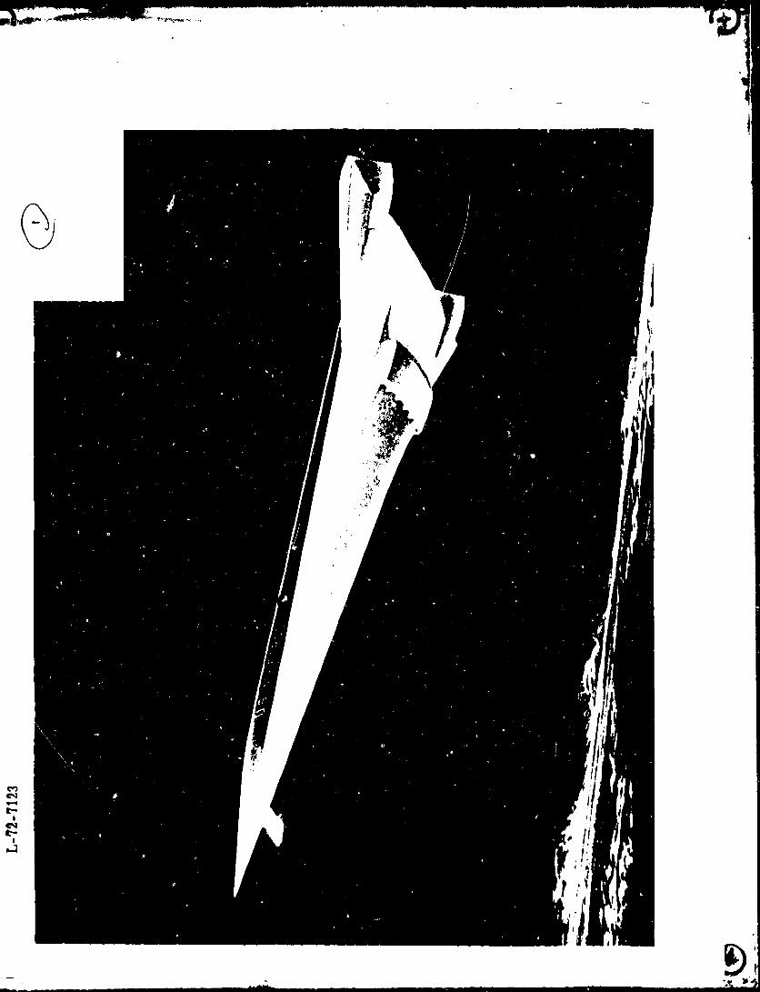
(1) [H£personic vehicle photo]
One example of an advanced aerospace vehicle operating at hypersonic speeds is
shown in this artist's rendition. Hypersonic speeds are those speeds in
excess of five times the speed of sound. For comparison, t_e supersonic
Concorde flies at only up to twice the speed of sound. At hypersonic speeds,
aerodynamic heating can become severe causing the surface to glow red to whitehot.
(2) [Hypersonic vehicle isotherms]Representative maximum temperature isotherms (in °F) are shown for a
conceptualized hypersonic vehicle. Local temperatures depend on vehicle
configuration, flight trajectory, and _peed. No lightweight structuralmaterials are available for use at temperatures above about 1600°F.
(3) [Specific strenqth]
Strength is an engineering property of considerably importance. A convenient
means of ranking different l,aterials for structural applicatioils when both
high strength and low weight are important is the strength of the material
divided by its density. This figure reveals that at temperatures above about
1600OF, carbon-carbon composites are unrivaled by other known materials.
(4) [Fabrication processing.]_Many steps are required to fabricate carborl-carbon composites. This block
diagram indicates the basic steps involved in fabricating _nprotected carbon-
carbon materials. Many variatior_ are possible.
(5} flaying up impregnated fabric]
Fabrication of a carbon-carbon part starts by first fabricating a carbon-resin
part. In this photograph, a carbon cloth impregnated with an uncured phenolic
resin is being smoothed down on a gently contoured mold plate. Additional
layers of cloth will be stacked until the desired thickness is reached. _ach
layer is smoothed as it is laid down usina a heat qun as an aid in softening
the tacky phenolic resin. Finally, the laid-up part will be cured in anautoclave. (Source: LTV Missiles and Electronics Group)
(6) [Pyrolysis fixture and I-beam]
Special fixtures are employed to maintain the shape of carbon-carbon parts
during cure and carbonization. A simple structural shape, an l-beam, is
st,)wn at the right "hile the special fixturinq (made of graphite) used tomaintain this shape during carbonization is _hown at the le/t. (Source: LTV
Missiles and Electronic_ Group)
(7) [Space Shuttle]The nose cap and wing leading edges of the Space Shuttle reach temperature_ of
2500°F. They are oxidation-resistant carbon-carbon composites. Althoughpopular attention has focused mostly on the ceramic tiles which protect thelower surfaces of the vehicle, these tiles are not serviceable at the higher
temperatures experienced by the nose cap and wing leading edges.

Maahs/Car_on-CarbonComposites
(8) [Leadinq edge attachment]
The oxidation-resistant carbon-carbon wing leading edge of the Space Shuttle
is attached to the wing structure in sections. The forward wing spar with
attachment hardware is shown at the right. A portion of the curved carbon-
carbon beat shield is visible at the left. In flight, tbe main airflow
approacbes from the lower left. The protective cover over much of the heat
shield is used tc prevent accidental damage during assembly and inspection.
(Source: NASA Johnson Space Center)
(9) [Oxidation-protection schemeslNumerous schemes have been explored for protecting carbon-carbon composites
from oxidation. The basic features of most of these schemes are depicted in
this schematic draying (not to scale). Many variations of these basicfeatures exist.
(10) [Stiffened panel]Efficient airframe structure requires ]arge, stiffened panels in complex
slapes. This small, !2-inch long panel illustrates tile complex shapes which
can be fabricated from carbon-carbon composites. (Source: BFGoodricb
Aerospace & Defense Divison)

¢
0

X !
0 U') 0 I.(3
o
uno0
0

C
q_ • •
&

_jl_ _ _ • • . , °_'l_¸ _ _
4e. _
_, I._r• _ _ll w_l,_

®

i

\
\
I_Ill

c-c_
0o
A
"_ o
_ _ x _
o_
!
C c-
8
-"_- _ili!!i
_\'4 J
,,\,_ ii_!iil
- "I ;:i_;I_
c_
C_
c__D
0M
c_D

ORIGINAL PAGE IS
OF POOR QUALITY
.4:
i,
| b
;/
