machine tools clamping division...machine tools clamping division translation of the original...
TRANSCRIPT

code 09ANCH001
version EN
revision 00
S a f e t y t h r o u g h p o w e r
PERMANENT - ELECTRO MAGNETIC SYSTEMS
USE AND MAINTENANCE
MANUAL Machine Tools Clamping Division
TRANSLATION OF THE ORIGINAL INSTRUCTIONS DIRECTIVE 2006/42/EC
Lainate (MI) - Italy Edition: June 2018

Use and Maintenance Manual MACHINE TOOLS CLAMPING DIVISION
2
code 09ANCH001
version EN
revision 00
Contents
page
1 GENERAL NOTES ..................................................................................................................................................... 5
1.1 PRESENTATION ...................................................................................................................................... 5
1.2 IMPORTANCE OF THE MANUAL .................................................................................................................. 5
1.3 RETENTION OF THE MANUAL .................................................................................................................... 5
1.4 CONVENTIONS....................................................................................................................................... 5
1.5 DEFINITION OF SYMBOLS ......................................................................................................................... 6
1.6 PERSONNEL ASSIGNED TO OPERATIONS....................................................................................................... 6
1.7 TRAINED PERSONNEL .............................................................................................................................. 6
1.8 PERSONAL PROTECTIVE EQUIPMENT (PPE) ................................................................................................. 6
1.9 GENERAL SAFETY WARNINGS .................................................................................................................... 7
1.10 EMERGENCY DRILL.................................................................................................................................. 7
1.11 UNINTENDED OR IMPROPER USE ............................................................................................................... 7
1.12 NAMEPLATE DATA .................................................................................................................................. 8
2 TRANSPORT AND HANDLING.................................................................................................................................. 9
2.1 RECEIPT ............................................................................................................................................... 9
2.2 HANDLING ............................................................................................................................................ 9
2.3 TRANSPORT .......................................................................................................................................... 9
2.4 INACTIVITY.......................................................................................................................................... 10
3 DESCRIPTION OF THE SYSTEM .............................................................................................................................. 10
3.1 ADVANTAGES ...................................................................................................................................... 10
3.2 BASIC PRINCIPLES OF MAGNETIC CLAMPING ............................................................................................... 10
3.3 FACTORS THAT DETERMINE THE MAGNETIC FORCE ...................................................................................... 10
3.3.1 AIR GAP AND ROUGHNESS ..................................................................................................................... 11
3.3.2 CONTACT SURFACE ............................................................................................................................... 11
3.3.3 TYPE OF MATERIAL ............................................................................................................................... 11
3.3.4 WORKPIECE SURFACE CONDITION ............................................................................................................ 11
3.3.5 MATERIAL THICKNESS ........................................................................................................................... 11
3.4 THE MAGNETIC FORCE........................................................................................................................... 11
4 AVAILABLE MODELS ............................................................................................................................................. 12
4.1 PERMANENT-ELECTRO MAGNETIC SYSTEMS ............................................................................................... 12
4.2 ELECTRONIC CONTROL UNIT .................................................................................................................. 12
5 TECHNICAL SPECIFICATIONS AND ELECTRICAL BASICS .......................................................................................... 13
5.1 TECHNICAL SPECIFICATIONS .................................................................................................................... 13
5.2 SUPPLY AND POWER ............................................................................................................................. 13
5.3 ELECTRICAL CONNECTIONS ..................................................................................................................... 14
5.4 CONNECTION TO THE SUPPLY .................................................................................................................. 14
5.5 POWER CABLE ..................................................................................................................................... 14
5.6 ENABLING XT200 AND ST200 CONTROL UNITS ........................................................................................ 14

Use and Maintenance Manual MACHINE TOOLS CLAMPING DIVISION
3
code 09ANCH001
version EN
revision 00
6 GENERAL DESCRIPTION OF THE SUPPLIES............................................................................................................. 15
6.1 XT200, XT200SK DESCRIPTION OF THE SUPPLIES ...................................................................................... 15
6.2 XT200, XT200SK KEYBOARD ................................................................................................................ 15
6.3 ST200 SEPARATE SUPPLIES ................................................................................................................... 16
6.3.1 ST200F, ST200FB, ST200SK, ST200RB DESCRIPTION OF THE SUPPLIES ..................................................... 16
6.3.2 ST200FA, ST200SKA DESCRIPTION OF SUPPLIES ..................................................................................... 17
6.3.3 ST200QE DESCRIPTION OF THE SUPPLY ................................................................................................... 17
6.3.4 ST200 SPECIAL IN CABINET DESCRIPTION OF THE SUPPLY ............................................................................ 18
6.4 ST200 DIFFERENT KEYBOARDS ............................................................................................................... 19
6.4.1 ST200 TCF KEYBOARD ......................................................................................................................... 19
6.4.2 ST200 TCF 3L KEYBOARD ..................................................................................................................... 20
6.4.3 ST200 TCR KEYBOARD (7 LEVELS) .......................................................................................................... 20
6.4.4 ST200 CH ENABLE KEYBOARD ............................................................................................................. 21
6.4.5 ST200 TCF4 KEYBOARD ....................................................................................................................... 21
6.4.6 ST200 TCF8 KEYBOARD ....................................................................................................................... 21
6.4.7 ST200 PCR1 KEYBOARD ...................................................................................................................... 22
6.4.8 ST200 PCR2 KEYBOARD ...................................................................................................................... 23
6.4.9 ST200 PCR3 KEYBOARD ...................................................................................................................... 23
6.4.10 ST200 PCR PLUS PUSH-BUTTON ............................................................................................................ 24
6.4.11 ST200 SPECIAL IN CABINET PUSH-BUTTON PANEL ...................................................................................... 24
7 INSTALLATION ...................................................................................................................................................... 25
7.1 GENERIC INSTALLATION ......................................................................................................................... 25
7.2 CONNECTION OF COMPONENTS AND SERIALIZATION OF THE CONTROLLERS ...................................................... 26
7.3 MILL-TEC GRIP INSTALLATIONS ............................................................................................................. 27
7.3.1 MILL-TEC GRIP ON HORIZONTAL BASE INSTALLATION .......................................................................... 27
7.3.2 MILL-TEC GRIP ON HORIZONTAL BASE REMOVAL ................................................................................ 28
7.3.3 MILL-TEC GRIP VERTICAL BASE INSTALLATION ..................................................................................... 29
7.3.4 MILL-TEC GRIP ON A VERTICAL BASE REMOVAL ................................................................................... 31
7.4 MILL-TEC GRIP DRILLING THE CHUCKS ................................................................................................... 32
8 RESIDUAL RISK ASSESSMENT ................................................................................................................................ 33
8.1 RISKS RELATED TO THE PERMANENT-ELECTRO MAGNET SYSTEM ..................................................................... 33
8.2 PERSONAL PROTECTIVE EQUIPMENT ......................................................................................................... 33
8.3 EXPOSURE TO MAGNETIC FIELDS ............................................................................................................. 33
9 NORMAL USE OF PERMANENT-ELECTRO MAGNETIC SYSTEM .............................................................................. 34
9.1 CLAMPING FORCE ................................................................................................................................ 34
9.2 CUTTING FORCE ................................................................................................................................... 34
9.3 PLACING THE WORKPIECE FOR MACHINING ON POLE EXTENSIONS ................................................................... 35
9.4 HOW TO CALCULATE THE CLAMPING FORCE ............................................................................................... 37
9.5 EXAMPLE OF MAGNETIC CHUCK CLAMPING FORCE CALCULATION.................................................................... 37
9.6 CLAMPING RULES FOR CONVENTIONAL MACHINING ..................................................................................... 37
9.6.1 FACE MILLING: DIRECT CLAMPING TO THE PERMANENT-ELECTRO MAGNETIC CHUCK .......................................... 37
9.6.2 FACE MILLING: CLAMPING ON POLE EXTENSIONS ........................................................................................ 38
9.6.3 THROUGH MACHINING OPERATIONS: CLAMPING ON POLE EXTENSIONS ........................................................... 38
9.6.4 MACHINING CYLINDRICAL WORKPIECES .................................................................................................... 38
9.6.5 MACHINING PARTS IN SERIES .................................................................................................................. 39
9.7 MACHINING EXAMPLES ......................................................................................................................... 39

Use and Maintenance Manual MACHINE TOOLS CLAMPING DIVISION
4
code 09ANCH001
version EN
revision 00
10 MAINTENANCE ..................................................................................................................................................... 41
10.1 SAFETY RULES DURING MAINTENANCE ...................................................................................................... 41
10.2 DAILY MAINTENANCE ............................................................................................................................ 41
10.3 WEEKLY MAINTENANCE ......................................................................................................................... 41
10.4 MONTHLY MAINTENANCE ...................................................................................................................... 41
10.5 SIX-MONTHLY MAINTENANCE ................................................................................................................. 41
10.6 EXTRAORDINARY MAINTENANCE ............................................................................................................. 41
10.7 INFORMATION FOR REPAIRS AND EXTRAORDINARY MAINTENANCE OPERATIONS ................................................ 42
11 PROBLEMS AND THEIR SOLUTIONS ...................................................................................................................... 42
11.1 PROBLEMS ......................................................................................................................................... 42
12 DECOMMISSIONING AND DISPOSAL .................................................................................................................... 43
12.1 DECOMMISSIONING ............................................................................................................................. 43
12.2 DISPOSAL ........................................................................................................................................... 43
13 SPARE PARTS ........................................................................................................................................................ 43
13.1 SPARE CONTROLLER AND PERMANENT-ELECTRO MAGNETIC CHUCKS ............................................................... 43
13.2 ADAPTORS PER CONNECTORS 7PIN – 10PIN – 5PIN ................................................................................. 43
13.3 SPARE KEYBOARDS (ONLY APPLICABLE FOR REMOTE CONTROL PANELS) ........................................................... 44
14 WARRANTY AND ASSISTANCE .............................................................................................................................. 45
14.1 WARRANTY CONDITIONS ....................................................................................................................... 45
14.2 INVALIDITY OF WARRANTY ..................................................................................................................... 45
15 TECNOMAGNETE SERVICE NETWORK ................................................................................................................... 46
16 ATTACHMENTS ..................................................................................................................................................... 46
16.1 DECLARATION OF CONFORMITY .............................................................................................................. 46

Use and Maintenance Manual MACHINE TOOLS CLAMPING DIVISION
5
code 09ANCH001
version EN
revision 00
1 GENERAL NOTES
Congratulations on choosing a TECNOMAGNETE product. This publication will help you find out more about your new product and we recommend that you carefully read these pages and always follow the instructions. The descriptions and illustrations contained in this publication are not difficult, given the basic features of the product described. TECNOMAGNETE reserves the right to make changes at any time to components and accessories in order to improve the product or due to manufacturing or commercial requirements. Updates of this manual will be provided as required as Annexes or on the website www.tecnomagnete.com . TECNOMAGNETE retains ownership of this manual and its reproduction, even partial, is prohibited, as is disclosure to third parties, without its written permission. In the event of changes and/or updates to the product, which will be agreed exclusively with TECNOMAGNETE, additional content concerning the use and any residual risks arising from the changes shall be provided to supplement the manual.
1.1 Presentation
TECNOMAGNETE was founded in 1974 and has attained a position of leadership position in world markets as a manufacturer of powerful, flexible permanent-electro magnetic systems that operate in total safety, due to its innovative technology and numerous patents filed over the years. Permanent-electro magnetic systems produced by TECNOMAGNETE are able to generate sufficient magnetic force both for clamping and lifting workpieces, only consuming electricity when turned on and off. The main fields of operation include:
MACHINE TOOLS CLAMPING SECTOR
Grinding series Milling series Turning series Rail machining series
MOULDING SECTOR
Systems for clamping press molds
LIGHT LIFTING SECTOR
Manually-controlled lifters Battery-powered lifters
HEAVY LIFTING SECTOR
Magnetic lifters Fixed beam magnetic module beam Telescopic beam magnetic module beam
1.2 Importance of the manual
A copy of this manual must be distributed and kept available to operators assigned to the installation, operation and maintenance of permanent-electro magnetic systems, enabling them to operate in accableance with the instructions given in this document. A careful reading of the manual will enable an permanent-electro magnetic system to be used in the correct way and safeguard the security and safety and operators and others. This manual is an integral part of the permanent-electro magnetic system, and all reproduction and dissemination rights of the manual and its attachments are reserved. Pass this manual on to any other user or subsequent owner.
1.3 Retention of the manual
Making changes to and removing parts of this manual are prohibited. When using the manual, take care not to damage it. Keep the CD-R or USB key away from impact, heat and magnetic sources and make it easily accessible to operators for further reference.
1.4 Conventions
For ease of consultation, the manual is divided into the following hierarchical order so that each phase is described in detail:
1. Chapter 1 of the manual 1.1. section 1 of Chapter 1 of the manual
1.1.1. sub-section 1 of section 1 of Chapter 1 of the manual
Some sections and/or chapters are presented with numbered sequences in order to illustrate the operation step by step. Symbols are given in sections requiring greater attention. Units of measurement, including the decimal point, are displayed with the international system (SI).

Use and Maintenance Manual MACHINE TOOLS CLAMPING DIVISION
6
code 09ANCH001
version EN
revision 00
1.5 Definition of symbols
All parts concerning safety are highlighted in bold. All warning notes that alert the personnel concerned that the described operation involves exposure to residual risk, with possible damage to health or injury, if not carried out in compliance with the instructions, are shown in bold and identified with the following symbol :
All warning notes that indicate that the described operation must be performed by trained and qualified personnel are shown in bold and indicated with the following symbol:
1.6 Personnel assigned to operations
As indicated in this manual, certain procedures must be carried out only by qualified or trained personnel. The level of qualification is described using standard terms:
1. qualified personnel have technical knowledge and/or sufficient experience to enable them to avoid the potential dangers from electricity and/or mechanical movements (operation and maintenance personnel)
2. trained personnel are appropriately advised and/or supervised by qualified persons to enable them to avoid the potential dangers from electricity and/or mechanical movements (operation and maintenance personnel)
3. the User is obliged to obtain confirmation of the following from all designated persons, before they are allowed to work to work with the permanent-electro magnetic system: 3.1. the personnel have received the instruction
manual, and have read and understood it 3.2. the personnel shall work in the manner described.
1.7 Trained personnel
The qualifications are given below of the personnel allowed to use the permanent-electro magnetic system:
OPERATOR: a person or persons who, following appropriate and indispensable training, is/are assigned and authorized by the owner of the electro-permanent magnetic system to run operations. The occupier of this post must be completely aware of and understand the contents of this manual
HANDLER: this post requires specific skills (possibly acquired by attending mandatory courses, if required by law) in handling hoists, the methods and features of harnesses and safe handling procedures. This position also requires complete awareness and understanding of the contents of this manual, in particular paragraph 2.2
MECHANICAL MAINTENANCE OPERATOR: this post requires specific skills in the installation, adjustment, maintenance, cleaning and/or repair of systems. The occupier of this post must be completely aware of and understand the contents of this manual.
ELECTRICAL MAINTENANCE OPERATOR (ref. EN60204 point 3.45): this post requires specific skills in carrying out electrical adjustments, maintenance and/or repairs and the ability to operate on live switchboards and electrical panels. The occupier of this post must be completely aware of and understand the contents of this manual.
1.8 Personal protective equipment (PPE)
The staff referred to in the previous paragraph must wear an adequate safety distance from the parts clamped on the magnetic equipment, with special attention when in vertical or suspended (this distance must be suggested by the plant operator in accordance with the regulations). The staff must also wear appropriate safety clothing. Protective footwear is mandatory, while the need for headsets, helmets and goggles must be assessed by the User. Loose fitting clothes or articles that could be trapped by moving parts are prohibited. (see chapter 8)

Use and Maintenance Manual MACHINE TOOLS CLAMPING DIVISION
7
code 09ANCH001
version EN
revision 00
1.9 General safety warnings
The rules and recommendations below are in compliance with the current safety regulations, on which they are based. Machine safety systems must be selected and installed on the basis of the following requirements: safety category 4 in accableance with the EN ISO 13849-
1 standard technical supervision by qualified staff integrated in technical compliance with suitable control
systems installations designed so they cannot be neutralized or
tampered with automatic surveillance of the electrical components, by
management software, for example. Moving parts must be furnished with mechanical safety devices
furnished with a STOP button locking system, in the event of hazardous movements and where errors occur or working conditions are abnormal
The machinery and equipment must be protected against electromagnetic interference when operating in environments with radio frequencies. TECNOMAGNETE S.p.A. declines any liability for any damage caused to persons and property arising from failure to comply with current safety regulations and the instructions below. All designated operators must respect and implement the following and scrupulously adhere to the regulations on accident prevention in force in the country of installation and on the use of the permanent-electro magnetic system. All ordinary and extraordinary maintenance must be performed with the machine halted and, if possible, with the power supply disconnected. To avoid the danger of accidental connections during maintenance operations, attach a warning sign on the control panel with the words:
SWITCH OFF WHILE MAINTENANCE IS UNDERWAY
Before connecting the main supply cable to the general panel clamp, checking the line voltage is appropriate in accableance with the plate on the panel. All operations of transport, installation, use, ordinary and extraordinary maintenance on the permanent-electro magnetic system must only be carried out by the personnel identified in section 6 of chapter 1.
The permanent-electro magnetic system can only be used for the applications indicated in the manual and only in combination with devices and components recommended and authorized by TECNOMAGNETE S.p.A.
1.10 Emergency drill
In an emergency, it is recommended to follow the procedures given in the operation and maintenance manual of the machine on which the permanent-electro magnetic system is installed. Safety systems, accableing to the type, should only provide the option of a manual restart after the fault or defect that caused the machinery to stop has been remedied. In the event of fire, use the devices provided to extinguish the fire, taking care never to use water on electrical parts.
1.11 Unintended or improper use
Permanent-electro magnetic systems are not designed or constructed for operation in explosive atmospheres. Unintended use may: cause injury to personnel damage the system or other equipment diminish reliability and performance. An electro-permanent magnetic system cannot be used for purposes other than those recommended and in compliance with the intended use, avoiding the following in particular: starting machinery by means of stop devices unsuitable parameters of use defective or lack of maintenance use of inappropriate materials failure to follow instructions uncertain or insecure clamping of permanent-electro
magnetic system or parts thereof. In the events of doubts over the appropriate usage, contact TECNOMAGNETE S.p.A. to determine whether it is use for which the system was intended or otherwise. For the magnetic clamping of special materials, other than those specified in this manual, the prior consent of TECNOMAGNETE S.p.A. must be obtained.

Use and Maintenance Manual MACHINE TOOLS CLAMPING DIVISION
8
code 09ANCH001
version EN
revision 00
Via Nerviano, 31 - Lainate (Milano) - Made in ITALY
RESIST.
COMANDO
PESO
TENSIONE
SETTIMANA ANNO
N° SERIECODICE/MODELLO
ASS.
1 2
4
6
8
3
5
7
5
3
7ASS.
TENSIONE MONOFASEVia Nerviano, 31 - Lainate (Milano) - Made in ITALY
CODICE/MODELLO
TEMPO DI CICLO SETTIM. ANNO
N° SERIE
PESO
DIMENSIONI
62
4
8
1
Via Nerviano, 31 - Lainate (Milano) - Made in ITALY
N° SERIE
KEYBOARD ST200
SETTIMANA . ANNO2 3
20020 - LAINATE (Milano)Via Nerviano, 31TECNOMAGNETE S.p.A.
Made in ITALY
0000 x 000 x 000 mm
V 000 V
MODELLO
IP 43 000 kg
SETTIM . ANNO N° SERIE
AC monoph f 50/60 Hz P max kVA
1 2 3
4
7
5 6
8 9
1.12 Nameplate data
The manufacturer’s identification plate is attached to permanent-electro magnetic systems, in compliance with the current laws. The plates must not be removed for any reason even should the permanent-electro magnetic be sold. In the event the plate has been damaged or lost after coming away from its housing, contact TECNOMAGNETE S.p.A. to obtain a replacement. When communicating with TECNOMAGNETE S.p.A., always quote the model on the plate. Failure to comply with these provisions exempts TECNOMAGNETE S.p.A. from any liability for damage or injury to persons or property that may arise, which shall remain the sole responsibility of the user with regard to the competent bodies. Example of a nameplate on an permanent-electro magnetic chuck:
❶ identifying alphanumeric code of the model
❷ registration number ❸ weight of the permanent-electro magnetic chuck
❹ the first two digits refer to the week of production, the other four digits to the year of manufacture
❺ type of electronic control unit that can be combined
❻ voltage and frequency of use ❼ resistance value of the permanent-electro magnetic chuck circuit
❽ maximum absorbed power
Example of a nameplate on the Electronic Control Unit: ❶ type of electronic control unit ❷ dimensions
❸ registration number ❹ cycle execution time
❺ absorbed power ❻ electronic control unit weight
❼ the first two digits refer to the week of production, the other four digits to the year of manufacture
❽ voltage and frequency of use
Example of a nameplate on the remote control panel: ❶ keyboard in combination with the electronic control unit ❷ registration number
❸ The first two digits are the week of production, the other four digits are the year of manufacture
Example of a nameplate on the Electronic Control Unit for in-case/cabinet commands: ❶ type of system used and voltage of use
❷ the first two digits refer to the week of production, the other four digits to the year of manufacture
❸ registration number
❹ operating voltage and whether single-phase or three-phase connection ❺ frequency of use
❻ maximum absorbed power ❼ dimensions
❽ degree of protection ❾ weight

Use and Maintenance Manual MACHINE TOOLS CLAMPING DIVISION
9
code 09ANCH001
version EN
revision 00
2 TRANSPORT AND HANDLING
2.1 Receipt
Permanent-electro magnetic systems are thoroughly checked before shipment. On receipt, the integrity of the package and the material contained therein must be checked (unless other instructions are issued by TECNOMAGNETE S.p.A.), in order to confirm that no damage occurred during transport and that the consignment complies with the order specifications. Otherwise, report any irregularities to TECNOMAGNETE S.p.A. and the Carrier responsible for any damage during transport. Notification of damage or defects must be given within ten days from receipt of the supply. After that period, TECNOMAGNETE S.p.A. will consider the provision free of defects.
2.2 Handling
The permanent-electro magnetic system can be transported in wooden crates. For ease of handling, the package can be placed on a pallet.
All personnel handling loads must operate with protective gloves and safety shoes. It is the responsibility of the user to ensure that handling is conducted in compliance with current safety regulations.
When hoisting or handling the permanent-electro magnetic system, clear the operations area of obstructions and keep it clear, also consider providing a sufficient safety zone to prevent harm to persons, animals or objects that might be in maneuvering range. The permanent-electro magnetic system is designed to be hoisted and handled with suitable hoisting devices, the type and scope of which must be selected in accableance with the weight. It must be handled with extreme care, avoiding impacts that could damage delicate parts, compromising normal operation. When moved with fork-lift trucks, comply with the permitted speed and inclination. Never leave load suspended on hoists.
The permanent-electro magnetic system must be disconnected from power sources and its moving parts appropriately locked during transport, handling and storage.
Do not handle the permanent-electro magnetic system with electromagnetic hoists.
The instructions on the package must be read and digested before opening. Keep the original packaging for later handling.
2.3 Transport
Some parts may have to be dismantled for transport, to be reassembled and reconnected during installation by TECNOMAGNETE S.p.A. technicians, or by the User on TECNOMAGNETE S.p.A.’s recommendations. The system must be transported in observance of the following environmental limits: a temperature range of -5 °C to +55 °C, rising to a maximum of +70 °C for a period no longer than 24 hours. Should it be necessary to transport the permanent-electro magnetic system by sea or by air, suitable packaging and protection systems must be provided to avoid any damage caused by impact. To protect against weathering, use anti-rust lubricants and bags of hygroscopic salts inside the packages. All moving parts must be properly anchored and removed from their housing, where possible.

Use and Maintenance Manual MACHINE TOOLS CLAMPING DIVISION
10
code 09ANCH001
version EN
revision 00
N S N S N S
N S N S N S N S N S N SS N S N S N
2.4 Inactivity
In the event of long-term storage or inactivity, the permanent-electro magnetic system must be thoroughly cleaned of any residues and its uncovered metallic parts must be protected with oil or grease in order to avoid oxidation. Disconnect the Electronic Control Unit from the permanent-electro magnetic system and the power line. It is recommended to cover the permanent-electro magnetic system and the Electronic Control Unit with a tarpaulin and keep them in a dry, sheltered place. The room temperature should be between -5 ° C (23 ° F) and + 55 ° C (131 ° F). The relative non-condensing humidity should be between 30% and 90%,. The atmosphere should be clean, free of acids, corrosive gases, salts, etc. If restoring to operation, follow the instructions contained in this manual.
3 DESCRIPTION OF THE SYSTEM
3.1 Advantages
Permanent-electro magnetic systems ensure the circulation of a continuous flow for an indefinite period since, during the work phases, they are independent of external power sources. Any interruption of the electricity supply cannot therefore alter the magnetic clamping force produced by the system. These are the so-called "COLD" magnetic clamping systems (where appropriate, see Chapter 11, only for cases in which the interruption of the electricity supply occurs during a cycle phase).
3.2 Basic principles of magnetic clamping
The lines of magnetic force (flux) lie between the north and south poles of an permanent-electro magnetic system.
This flux can be used to attract and block ferrous elements. In a steel part crossed by a magnetic field, opposite polarity is induced to that of the source flux and attraction is exerted until contact is made.
The flux induced in the steel depends on the material is made of, its size, the quality of contact established between the workpiece to be clamped and the permanent-electro magnetic system, and the ease with which the flux can pass through the steel.
3.3 Factors that determine the magnetic force
The amount of magnetic flux induced in the workpiece is the determining factor of the clamping force. For optimal clamping, the greatest magnetic flux possible must be induced in the workpiece. To achieve this, it is important to:
place the workpiece between the North and South poles of the permanent-electro magnet system
ensure optimal contact between the workpiece and permanent-electro magnetic system
cover the greatest number of North and South poles (check the number of operative poles, and multiply this value by the unit value in cm² of the pole. (QX/RQ HE50/HD50: 25 cm² – QX HD70: 49 cm² – Mill-TEC GRIP/
BASIC: 40 cm²) the workpiece’s short-circuitry should have sufficient
thickness.
The clamping force is proportional to:
the square of the magnetic flux density in the face in contact with the workpiece
workpiece area in contact with the magnetic chuck, up to the maximum point of its saturation.
By halving the contact area, the clamping force is also halved and, if the density of the magnetic flux is halved, the strength is reduced by 75%. So reductions in the flux density influence the magnetic force developed.
Air gaps are an immediate example (an air gap is the average contact distance between the workpiece to be clamped and the source of magnetic flux). The main factors that can affect the flux density and the magnetic clamping of a workpiece of any size are described in the following paragraphs.
MAGNETIC CHUCK
MAGNETIC MODULE
STEEL
Percentage 100%
100%
Cla
mp
ing
stre
ngt
h
Area
flux density
STEEL
MAGNETIC MODULE

Use and Maintenance Manual MACHINE TOOLS CLAMPING DIVISION
11
code 09ANCH001
version EN
revision 00
N S N S N S
3.3.1 Air gap and roughness
The condition that guarantees the highest performing magnetic attraction is obtained when air gaps are minimized and there is a substantial area of continuous contact. The worst results occur with the highest number of air gaps and minimum contact. A very important aspect is therefore the degree of surface roughness. A good contact surface decreases the air gaps considerably, thereby achieving an optimal force of magnetic attraction.
100% = adjusted 90 ÷ 80% = fine milled 80 ÷ 70% = milled 70 ÷ 60% = untreated
3.3.2 Contact surface
To ensure excellent magnetic performance, the greatest number of North and South poles must be covered in equal amounts. The magnetic attraction force is directly proportional to the useful area of contact (for further details see section 3.3).
3.3.3 Type of material
Check the type of material to be magnetically clamped. The technical property required from the material is its magnetic conductivity (magnetic permeability). The most permeable material is mild steel, while for different materials consider the following reduction factors: 1,0 mild steel 0,7 ÷ 0,8 alloy steel 0,5 cast iron 0,2 nickel 0 (zero) non-magnetic stainless steel, brass, aluminium These values are to be used for clamping force calculation (see example to section 9.5)
3.3.4 Workpiece surface condition Surface heat treatment of materials affects their physical structure, as well as the ability to absorb the magnetic flux. Annealed materials are best. Hardened materials do not satisfactorily absorb the flux and have a tendency to retain a certain amount of magnetism when the chuck is deactivated (DEMAG). It may sometimes be difficult to remove the workpiece from the permanent-electro magnetic system due to the residual magnetism of the piece. This residual magnetism can be eliminated with a demagnetizer.
3.3.5 Material thickness
As an approximation, it can be assumed that the path of the magnetic flux in a magnetically clamped workpiece is formed of a semicircle, starting from the centre of a pole (North) and reaching the centre of the next (South). If the workpiece fails to contain all the magnetic flux generated, the surplus leaks out and does not contribute to the clamping. The resulting attraction will therefore be less than when the entire flow is absorbed by a workpiece of sufficient thickness to contain it.
CHECK THE THICKNESS OF THE WORKPIECE TO BE MACHINED
If the thickness of the workpiece to be machined is insufficient, once magnetically clamp, a magnetic residue will be seen on the surface opposite to that of contact, and the performance of the magnetic chuck will be reduced as a consequence.
3.4 The magnetic force
Each pole (North/South) of the permanent-electro magnetic system is an independent magnetic island, consisting of a magnetic flux conductor steel core, capable of generating a high magnetic force, concentrated and constant over time (under optimal conditions, it is 16 daN/cm²). The total force of magnetic attraction available is directly proportional to the operating magnetic surface, the type of material to be machined and the condition of its surface.
Material to be machined (mild steel, alloy steel, cast iron ....) Conditions of the workpiece surface (roughness, flatness ....) Workpiece flat contact surface (meaning the surface is
in contact with the poles).
As already pointed out, the value of the magnetic force decreases as the air gap increases.
clamping strength
WORKPIECE TO BE MACHINED
MAGNETIC CHUCK
Air gap (mm)
Forc
e/p
ole

Use and Maintenance Manual MACHINE TOOLS CLAMPING DIVISION
12
code 09ANCH001
version EN
revision 00
4 AVAILABLE MODELS
4.1 Permanent-electro magnetic systems
For the Machine Tools Clamping Division, TECNOMAGNETE divides magnetic-permanent-electro chucks into the following categories:
GRINDING series: TFP0/T - TFP1/T - TPF/T - TPF/C - RP/C - HQ 50
Spark Erosion series: MDS
MILLING series: QX HE50/HD50 - QX HD70 - Mill-TEC - RQ HD50
Mill-GRIP TEC/R - Mill-TEC GRIP - Mill-TEC BASIC (5 Pin 10
Pin Ergon)
CUBOTEC series: Cubotec CT1 Mill-TEC GRIP - Cubotec CT2 Mill-TEC GRIP
MAGNETIC PALLET series: Pall-TEC PT/M - Pall-MAG
MODULAR CHUCK series: Uniblock - Quad-Block - Block Quad-GRIP
RAIL MACHINING series: Quad-RAIL (see the dedicated user manual)
RADIAL series: Radial-POLE and Flexo-MAG (see the dedicated user manual)
Moreover, combined with the permanent-electro magnetic chucks, TECNOMAGNETE is able to provide the polar extensions that represent an innovative, unique and patented technical solution, arising from the need to clamp workpieces on even levels or warped surfaces.
MOBILE pole extensions: PMQ - RPM - RPM/SC
FIXED pole extensions:
PRF - PRF/SC
4.2 Electronic Control Unit
XT200 and ST200 are systems described as Electronic Control Units (hereinafter, referred to as the Control Unit) Unit for combination with a number of permanent-electro magnetic systems.
Chapter 6 gives descriptions of the supplies (and the operation of the respective keyboards) of the following Control Units:
XT200 (Milling) ST200F, ST200FB, ST200FA, ST200SK, ST200SKA
(Milling) ST200RB, ST200QE (Grinding) ST200 Special in cabinet

Use and Maintenance Manual MACHINE TOOLS CLAMPING DIVISION
13
code 09ANCH001
version EN
revision 00
5 TECHNICAL SPECIFICATIONS AND ELECTRICAL BASICS
5.1 Technical specifications
In this manual, the term "cycle" refers to pressing the MAG/SAFE/DEMAG buttons for a power running in order to obtain a state of magnetization/demagnetization. The XT200 and ST200 Control Units are suitable for use in the environments and operating conditions given below:
Control Unit
Noise emission <70dB
Voltage nominal ± 10%
Frequency nominal 50/60Hz ± 1%
Operating temperature da -5°C a +40°C (23°F ÷ 104°F)
Humidity <80% at + 40 ° C (104 ° F)
Degree of protection IP43 for XT200 and ST200
Degree of protection IP43 intermediate junction boxes
Degree of protection IP40 for all pushbutton panels
Maximum altitude 2000m above sea level
Time keys pressed Minimum 500ms (0.5 seconds)
Radius of cable curvature Minimum of 10 times the diameter
Max cable traction 15N/mm²
Number of cycles max 20 cycles/hour
Permanent-electro Magnetic Chucks
Operating temperature max + 80°C (176°F)
Degree of protection IP65
5.2 Supply and Power The nominal operating voltage of an permanent-electro magnetic chuck must correspond to the nominal voltage of the Control Units. The values of the nominal voltages of use for the ST200 and XT200 Control Units are identified by the following abbreviations:
V1 = 200V V2 = 230V
V3 = 380V/400V/415V/440V V4 = 460V/480V
In the event of the installation of permanent-electro magnetic chucks with different nominal voltages, a transformer with a suitable ratio for the purpose and, of course, with a nominal power sufficient for the maximum power of the magnetic chuck.
To ensure optimum safety during the activation cycles, it is important that an earth connection is made to the Control Unit and that earthing system is fully operational (connection to be made through the main supply cable provided with XT200 and ST200 ).
The XT200 and ST200 Control Unit consists of:
Controller Keyboard DB9 key-lock In subparagraph 6.4.7, however, the DB9 stopper is described as an alternative to the DB9 key-lock.
The outside of the XT200 Controller is made of a plastic housing while the ST200 Controller housing is made of metal cable connected to the lid is assembled inside the ST200, which must not be removed, in turn connected to earth cables. Short-circuit protection is the responsibility of the user and must be ensured by a suitable system positioned upstream of the Control Unit. It is advisable to incorporate a thermal-magnetic switch in the C curve with the value of In taken from the data on the nameplate of the magnetic chuck to which the Control Unit shall be connected. The maximum power for XT200 and ST200 is roughly:
15 KVA (cosϕ = 0.9) for a supply voltage of 230V single-phase
25KVA (cosϕ = 0.9) for a supply voltage of 400V single-phase
30KVA (cosϕ = 0.9) for a supply voltage of 480V single-phase
The current absorbed is the impulsive type. TECNOMAGNETE Control Units directly use the power grid via a sophisticated splitting process. They always and only operate with the machine stopped and usually need a lower effective current than required to operate the machine on which the permanent-electro magnetic chuck to be controlled is installed. Should there be a need for the Control Unit to perform/repeat the cycles with very brief intervals, a respective increase in temperature must be considered in the permanent-electro magnetic chuck. We therefore recommend avoiding running unnecessary cycles.
DO NOT PERFORM REPEATED MAGNETIZING AND DEMAGNETIZING CYCLES WITHOUT A SUFFICIENT TIME INTERVAL (see section 5.1)
IT IS ALSO PROHIBITED TO CHANGE THE FACTORY SETTINGS ON TECNOMAGNETE SYSTEMS

Use and Maintenance Manual MACHINE TOOLS CLAMPING DIVISION
14
code 09ANCH001
version EN
revision 00
12345
9 8 7 6
ENABLE
CHIAVETTA DB9
ENABLE
VISTA INTERNA / INTERNAL SIDE
CONTROLLERMACHINE
5.3 Electrical connections
The operations to connect electrical equipment must be performed by skilled personnel. It is vital that the electrical supply plant, including the place where the Control Unit is to be installed, is carried out in accableance with the current regulations.
TECNOMAGNETE cannot be held liable for any damage caused by a failure to earth the system. It will be the responsibility of the customer to ensure that the Control Unit is protected. The wiring diagrams must be consulted in combination with the type of machinery to be installed.
5.4 Connection to the supply
XT200 and ST200 can be connected to the distribution grid via the multipolar cable provided, which has three wires suitable for the purpose. Connection to the distribution grid depends on the plate both on the controller and the respective permanent-electro magnetic chuck. The following wiring diagrams simplify the process of connecting the controller to the appropriate power supply.
5.5 Power cable
For XT200 and the ST200, TECNOMAGNETE provides a 4 meter long, multipolar power cable suitable for the purpose. Under normal operating conditions, there are no overheating problems and a fall in the voltage required to power TECNOMAGNETE systems. For longer than standard lengths, the diameter of the wire must ensure a voltage drop of less than 1%. Caution: the control unit is supplied without a mains connection plug.
5.6 Enabling XT200 and ST200 Control Units
XT200 and ST200 are supplied with a key with a DB9 connector (referred to as the DB9 key-lock) inside which (by means of the PIN) the following signals can be found:
pin # 1 ➜ B1
pin # 2 ➜ A2
pin # 3 ➜ VDC
pin # 4 ➜ Cnd
pin # 5 ➜ Alarm
pin # 6 ➜ COM ENABLE Controller
pin # 7 ➜ ENABLE Controller
pin # 8 ➜ COM ENABLE machine
pin # 9 ➜ ENABLE machine
The voltages of use for the 8 and 9 PINs of the DB9 are the following:
Voltage 24V to 30V - max current 1A
Voltage 110V - max current 0,3A
A 120 Ω resistance is soldered between PINs 1 and 2, useful for the correct balance in the internal communication of Control Unit.
The DB9 key-lock is connected to the Control Unit in accableance with the examples in paragraph 7.2 and allows both a Controller enabling service (Controller Enable) and an enabling service for the machine (Machine Enable) as described below:
Controller Enable: from PINs 6 and 7, it is possible to enable/disable the controller to perform the cycles; when PINs 6 and 7 are closed, the Controller Enable is active and enabled the cycles to be performed, which is not possible when they are open. It is recommended that an auxiliary relay is always used for the Controller Enable.
Machine Enable: when at least one of the magnetic chucks managed by the Controller is in a state of magnetization, the Machine Enable (PINs 8 and 9) is closed.
In sub-section 6.4.7, the DB9 stopper is given as an alternative to the DB9 key-lock should the Control Unit use a specific keyboard (hereinafter, referred to as PCR1) with signals for interfacing to a PLC system.
Single-phase power supply network
200V ÷ 230V
F
N
PE
BLACK
BLACK
YELLOW GREEN
Controller XT200/ST200
Three-phase power supply network
380V ÷ 480V
R
S
T
PE
BLACK
BLACK
YELLOW GREEN
Controller XT200/ST200
Use and Maintenance Manual MACHINE TOOLS CLAMPING DIVISION
15
code 09ANCH001
version EN
revision 00
L2
D
L1
B
A
70mm
230mm
190mm
C
MAG DEMAG
5 1 724 6 3
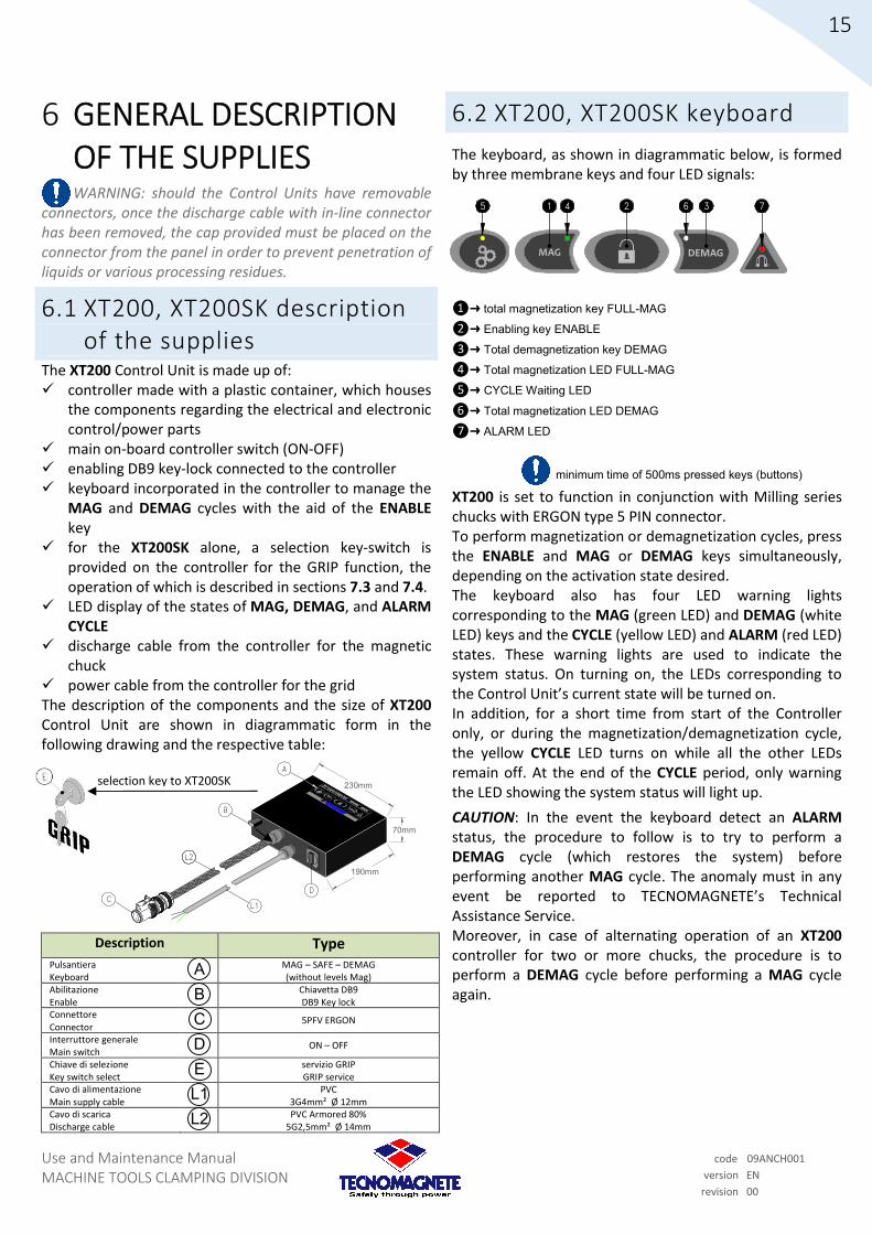
6 GENERAL DESCRIPTION OF THE SUPPLIES
WARNING: should the Control Units have removable connectors, once the discharge cable with in-line connector has been removed, the cap provided must be placed on the connector from the panel in order to prevent penetration of liquids or various processing residues.
6.1 XT200, XT200SK description of the supplies
The XT200 Control Unit is made up of: controller made with a plastic container, which houses
the components regarding the electrical and electronic control/power parts
main on-board controller switch (ON-OFF) enabling DB9 key-lock connected to the controller keyboard incorporated in the controller to manage the
MAG and DEMAG cycles with the aid of the ENABLE key
for the XT200SK alone, a selection key-switch is provided on the controller for the GRIP function, the operation of which is described in sections 7.3 and 7.4.
LED display of the states of MAG, DEMAG, and ALARM CYCLE
discharge cable from the controller for the magnetic chuck
power cable from the controller for the grid The description of the components and the size of XT200 Control Unit are shown in diagrammatic form in the following drawing and the respective table:
Description Type Pulsantiera Keyboard
A MAG – SAFE – DEMAG (without levels Mag)
Abilitazione Enable
B Chiavetta DB9 DB9 Key lock
Connettore Connector
C 5PFV ERGON
Interruttore generale Main switch
D ON – OFF
Chiave di selezione Key switch select
E servizio GRIP GRIP service
Cavo di alimentazione Main supply cable
L1 PVC 3G4mm² Ø 12mm
Cavo di scarica Discharge cable
L2 PVC Armored 80% 5G2,5mm² Ø 14mm
6.2 XT200, XT200SK keyboard
The keyboard, as shown in diagrammatic below, is formed by three membrane keys and four LED signals:
❶➜ total magnetization key FULL-MAG
❷➜ Enabling key ENABLE
❸➜ Total demagnetization key DEMAG
❹➜ Total magnetization LED FULL-MAG
❺➜ CYCLE Waiting LED
❻➜ Total magnetization LED DEMAG
❼➜ ALARM LED
minimum time of 500ms pressed keys (buttons)
XT200 is set to function in conjunction with Milling series chucks with ERGON type 5 PIN connector. To perform magnetization or demagnetization cycles, press the ENABLE and MAG or DEMAG keys simultaneously, depending on the activation state desired. The keyboard also has four LED warning lights corresponding to the MAG (green LED) and DEMAG (white LED) keys and the CYCLE (yellow LED) and ALARM (red LED) states. These warning lights are used to indicate the system status. On turning on, the LEDs corresponding to the Control Unit’s current state will be turned on. In addition, for a short time from start of the Controller only, or during the magnetization/demagnetization cycle, the yellow CYCLE LED turns on while all the other LEDs remain off. At the end of the CYCLE period, only warning the LED showing the system status will light up.
CAUTION: In the event the keyboard detect an ALARM status, the procedure to follow is to try to perform a DEMAG cycle (which restores the system) before performing another MAG cycle. The anomaly must in any event be reported to TECNOMAGNETE’s Technical Assistance Service. Moreover, in case of alternating operation of an XT200 controller for two or more chucks, the procedure is to perform a DEMAG cycle before performing a MAG cycle again.
selection key to XT200SK

Use and Maintenance Manual MACHINE TOOLS CLAMPING DIVISION
16
code 09ANCH001
version EN
revision 00
CH1
CH3
CH2
CH4
PATENTED SYSTEM MADE IN IT ALY
PATENTED SYSTEM MADE IN ITALY
CH1
CH3
CH2
CH4
PATENTED SYSTEM MADE IN ITALY
CH1
CH3
CH2
CH4
PATENTED SYSTEM MADE IN ITALY
PATENTED SYSTEM MADE IN ITALY
B
L1L2
L3
A
275mm
331mm
Example
135mm90mm
40mm
C
85mm
E
A
Exam
ple
per ST200F, ST200FB, ST200SK
D
6.3 ST200 Separate supplies
Supplies of ST200 Control Units are divided (depending on their manufacturing components) into the following sub-sections:
6.3.1 for ST200F, ST200FB, ST200SK, ST200RB
6.3.2 for ST200FA, ST200SKA
6.3.3 for ST200QE
6.3.4 for ST200 Special in cabinet
6.3.1 ST200F, ST200FB, ST200SK, ST200RB
Description of the supplies
The ST200F, ST200FB, ST200SK and ST200RB Control Units consisting of:
controller made with metal container housing the components regarding the electrical and electronic control/power parts
Main on-board controller switch (ON-OFF)
enabling by DB9 key-lock connected to the controller
for the ST200SK only, a key-switch select is provided on-board the controller for the GRIP service, the operation of which is described in sections 7.3 and 7.4.
keyboard placed outside the controller to handle the MAG and DEMAG cycles with the help of the ENABLE key (in some models, magnetization levels can be managed with dedicated keys), with external keyboard, a cable to connect to the controller is also included
LED panel displaying the states of MAG, DEMAG, CYCLE and ALARM (LEVEL +/- LEDs are shown for models that include magnetization levels)
discharge cable from the controller to the magnetic chuck. Moreover, TECNOMAGNETE defines the installation of multiple magnetic chucks as “banked” and, in this case, the discharge cable from the controller could provide the connection to an intermediate junction box
power cable from the controller for the grid
The description of the components and dimensions of the ST200F, ST200FB, ST200SK and ST200RB Control Units are shown in diagrammatic format in the following drawings and the respective table:
Description Type Interruttore generale Main switch
A ON - OFF
Abilitazione Enable
B chiavetta DB9 DB9 Key lock
Pulsantiera remota Remote control
C MAG - SAFE - DEMAG (Some type levels included Sp)
Connettore Connector
D example: FEME example: FEME
Chiave di selezione Key switch select
E GRIP service GRIP service
Cavo di alimentazione Main supply cable
L1 PVC 3G4mm² Ø 12mm
Cavo di scarica Discharge cable
L2 PVC Armored (for ST200F, ST200FB, ST200SK) PVC (for ST200RB)
Cavo della pulsantiera Cable of remote control
L3 Shielded PVC/PVC screened 5 coaxial 22AWG x Ø 9mm
Some examples of keyboards that can be used for for the keyboard:
keyboard without magnetization levels (sign as TCF)
keyboard with three levels of magnetization (sign as TCF 3L)
keyboard with seven levels of magnetization (sign as TCR)
keyboard interfacing with PLC systems (sign as PCR1)
complete keyboard: keyboard without magnetization levels plus a keyboard for select (sign as TCF4) or with two keyboard for select (sign as TCF8)
Key switch select to ST200SK

Use and Maintenance Manual MACHINE TOOLS CLAMPING DIVISION
17
code 09ANCH001
version EN
revision 00
B
L1
J1
J2
J3
PE
PE
PE
PE
COMM
COMM
COMM
COMM
CH1
CH2
CH3
CH4
IN
IN
OUT
OUT
R
S
T
N
PE
140mm110mm
135mm90mm
40mm
A
X
L2
X=145mm per ST200QE 1sch or 2sch
X=210mm per ST200QE 4sch
L3
E
A
B
L1
D
275mm
331mm
ST200FA
85mm
L2
C
AD
6.3.2 ST200FA, ST200SKA Description of supplies
The ST200FA Control Unit, are ST200SKA consisting of:
controller with metal container inside which the components are housed related to the electrical and electronic part of command/power
Main switch on board of the controller (ON-OFF) qualifications through DB9 key-lock connected to the
controller built-in keyboard to the controller to manage the MAG
and DEMAG cycles with the aid of the ENABLE key (only for ST200SKA it is also provided, on board of the controller, a key switch select for the GRIP function whose operation is described in sections 7.3 and 7.4).
LED display control panel in the states of MAG, DEMAG, and ALARM CYCLE
discharge cable from the controller to the magnetic chuck
power cable from the controller to the network
The description of the components and the size of the ST200FA and ST200SKA Control Unit are shown in diagrammatic form in the following drawings and the related table:
Decription Type Tastiera Keyboard
A MAG - SAFE - DEMAG
Abilitazione Enable
B chiavetta DB9 DB9 Key lock
Connettore 10P Ergon Connector 10P Ergon
C 10PFV Ergon
Interruttore generale Main switch
D ON - OFF
Chiave di selezione Key switch select
E GRIP service GRIP service
Cavo di alimentazione Main supply cable
L1 PVC 3G4mm² Ø 12mm
Cavo di scarica Discharge cable
L2 PVC Armored 80% 10x2mm² Ø 15.7mm
6.3.3 ST200QE Description of the supply
The ST200QE Control Unit is made up of:
controller with metal container housing the components related to the electrical and electronic control /power part
provision of a remote-control switch in the terminal box at the responsibility of the customer (in addition, a number of alternatives, for example using the contacts of a relay, remain the responsibility of the cust, as detailed in the specific wiring diagram)
enabling by DB9 key-lock connected to the controller keyboard placed outside the controller to handle the
MAG and DEMAG cycles, with the help of the ENABLE key (for some models, it is possible to manage the magnetization levels using dedicated keys), with the external panel, a cable for connecting to the controller is also included
LED panel displaying the states of MAG, DEMAG, CYCLE and ALARM (LEVEL +/- LEDs are displayed for models that include the levels of magnetization)
discharge cable from the controller to the magnetic chuck
The description of the components and the dimensions of the ST200QE Control Unit are shown in diagrammatic form in the following drawing and respective table:
Description Type Pulsantiera remota Remote control
A MAG - SAFE - DEMAG (Some type levels included levels mag)
Abilitazione Enable
B chiavetta DB9 DB9 Key lock
Cavo di alimentazione Main supply cable
L1 At customer's charge At customer charge
Cavo di scarica Discharge cable
L2 PVC or PVC Armored in accableing with magnetic chuck type
Cavo della pulsantiera Cable of remote control
L3 PVC shielded 5 coaxial 22AWG x Ø 9mm
Key switch select to ST200SKA

Use and Maintenance Manual MACHINE TOOLS CLAMPING DIVISION
18
code 09ANCH001
version EN
revision 00
F
6.3.4 ST200 Special in cabinet Description of the supply
The ST200 Special in cabinet Control Unit can be made both with external push-button panel (identified by the abbreviation CCE) or with push-button panel incorporated in the controller’s hatch (identified by the abbreviation CCU).
Both types of ST200 Special in cabinet Control Unit are made up of:
controller made with metal case/cabinet housing the components related to the electrical and electronics control/power part
Main on-board controller switch (ON-OFF)
on-board controller network light for on/off system alerts
Controller activation via the Controller Enable contacts (or Input Enable) wired in the controller’s terminal box
for the ST200 Special SK model only, a key switch select is provided for the GRIP service, placed on the controller’s hatch, the function of which is described in sections 7.3 and 7.4.
push-button panel to manage MAG and DEMAG cycles with the aid of the ENABLE button (for some models, magnetization levels can be managed via dedicated buttons). For banked panels, single and multiple magnetic chucks can be selected. A cable to connect to the controller is provided with the external push-button panel
LED control panel displaying the states of MAG, DEMAG, CYCLE and ALARM (LEVEL +/- LEDs can be displayed for models that include the magnetization levels). For banked panels in which selections are required, the push-button panel includes the buttons and respective SELECT LEDs
discharge cables from the controller(s) to the magnetic chuck(s). For banked panels, the discharge cable from the controller could provide the connection to one or more intermediate junction boxes
Optional: Radio Control (identified by the abbreviation RCM) including receiver housed inside the controller, with antenna that can be placed externally and the portable transmitter with MAG, DEMAG, SAFE, POWER functions (complete set of batteries and battery chargers)
Optional: external alert lights for additional display of the states of MAG, DEMAG, CYCLE and ALARM
The size of the ST200 Special in cabinet Control Unit is tied to the number of permanent-electro magnetic chucks to be activated.
Some examples with the respective table are given below:
ST200 Special in cabinet abbreviated as CCU
A1
ST200 Special in cabinet abbreviated as CCE
B
L1A2
L2
L3
X1
C
DE
IP43
IP43
IP40
Description Type Pulsantiera remota Remote control
A MAG-SAFE-DEMAG-SELECT A1=integrated A2=remote
Controller Controller B box or cabinet
Connettore Connector C Example: FEME or HARTING
Interruttore generale Main switch D ON - OFF
Lampada di rete Main lamp E
LED bianco white LED
Lampade esterne External lamps F
Verde/Bianca/rossa/gialla green/white/red/yellow
Cavo di alimentazione Main supply cable L1
PVC 3G4mm² Ø 12mm
Cavo di scarica Discharge cable L2
PVC or PVC Armored in accableance with magnetic chuck type
Cavo della pulsantiera Cable of remote control L3
PVC Example 25G0,5mm² Ø 13mm
Cassetta di derivazione Junction box X1 Example: ILME_19

Use and Maintenance Manual MACHINE TOOLS CLAMPING DIVISION
19
code 09ANCH001
version EN
revision 00
6
PATENTED SYSTEM MADE IN ITALY
1 2 3
4
7
5
6.4 ST200 Different keyboards
The keyboards for the ST200 Control Unit differ, depending on their configuration, in the membrane keys and operation. They are described in the following sub-sections:
6.4.1 for TCF
6.4.2 for TCF 3L
6.4.3 for TCR
6.4.4 for CH Enable
6.4.5 for TCF4
6.4.6 for TCF8
6.4.7 for PCR1
6.4.8 for PCR2
6.4.9 for PCR3
6.4.10 for PCR Plus
6.4.11 for SPECIAL push-button (for cabinet control)
CAUTION: For all keyboards of the ST200 Control Unit, in the event the ALARM state is detected, the procedure to be followed is to try to perform a DEMAG cycle (which resets the system) before performing a MAG cycle again. The anomaly must, in any case, be reported to TECNOMAGNETE’s Technical Assistance Service.
In the event a single ST200 controller is used to alternate the operation of two or more magnetic chucks, it must be taken into account that the Controller‘s memory will contain the system state of the last performed cycle. Therefore, when detaching the controller from the current magnetic chuck and connecting it to another magnetic chuck, the procedure involves performing a DEMAG cycle before performing a MAG cycle.
For all ST200 Control Unit keyboards, the yellow CYCLE LED lights up while all the others remain off for a short time after starting the controller, or during the magnetization/demagnetization cycles. At the end of the CYCLE period, only the alert LED light turns on to represent the system status.
For every ST200 keyboard, a summary table is given of the system states with the corresponding LED operation.
The following abbreviations for LED operation are used:
AF = LED On Steady
AL = LED On Flashing
SP = Led Off
6.4.1 ST200 TCF keyboard
The keyboard, shown in diagrammatic form below, is made up of three membrane keys and eight alert LEDs:
❶➜ Total magnetization key FULL-MAG
❷➜ Enabling key ENABLE
❸➜ Total demagnetization key DEMAG
❹➜ Total magnetization LED FULL-MAG
❺➜ CYCLE Waiting LED
❻➜ Total magnetization LED DEMAG
❼➜ ALARM LED
minimum time of 500ms pressed keys
This keyboard is the basic model for the ST200 Controllers and can be used for both Milling and Grinding systems. To carry out the cycles of magnetization or demagnetization, press the ENABLE key and the MAG, or the DEMAG key at the same time, depending on the activation state to be obtained. The keyboard also has eight LED alert lights placed in correspondence with the MAG (green LED) and DEMAG (white LED) keys and the CYCLE (yellow LED) and ALARM (red LED) states. These lights are used to indicate the system status. When the power will be turned on, the LEDs corresponding to the current state of the controller will turn on.
System Status MAG LED
DEMAG led
CYCLE LED
ALARM LED
Full-Mag AF SP SP SP
Demag SP AF SP SP
Cycle in progress SP SP AF SP
Alarm current SP SP SP AF
Alarm Communications SP SP SP AL

Use and Maintenance Manual MACHINE TOOLS CLAMPING DIVISION
20
code 09ANCH001
version EN
revision 00
6
PATENTED SYSTEM MADE IN ITALY
1
2
3
4
7
5
9 8
1
2
3
4
5
6
7
8
PATENTED SYSTEM MADE IN ITALY
4 5
2 7
1
3
6
8
9
10
6.4.2 ST200 TCF 3L keyboard
The keyboard, as shown in diagrammatic form below, is made up of five membrane keys and eight alert LEDs:
❶➜ Total magnetization key FULL-MAG
❷➜ Enabling key ENABLE
❸➜ Total demagnetization key DEMAG
❹➜ Total magnetization LED FULL-MAG
❺➜ CYCLE Waiting LED
❻➜ Total magnetization LED DEMAG
❼➜ ALARM LED
❽➜ 1st level partial magnetization key MAG 1L
❾➜ 2nd level partial magnetization key MAG 2L
minimum time of 500ms pressed keys
This ST200 panel can be used both in Milling and Grinding systems Grinding should it be necessary to manage three different levels of magnetization. To perform the magnetization or demagnetization cycles, press the ENABLE key at the same time as one of the following: MAG 1L, MAG 2L, FULL-MAG or DEMAG, depending on the activation state desired. The keyboard also has eight LEDs placed in correspondence with the MAG (green LED) and DEMAG (white LED) keys and the CYCLE (yellow LED) and ALARM (red LED) states. These lights are used to indicate the system state. When the power is turned on, the LEDs corresponding to the controller’s current status will be on.
System Status MAG LED
DEMAG LED
CYCLE LED
ALARM LED
Full-MAG AF SP SP SP
MAG 1L AL SP SP SP
MAG 2L AL SP SP SP
Demag SP AF SP SP
Cycle in progress SP SP AF SP
Alarm current SP SP SP AF
Alarm communication SP SP SP AL
6.4.3 ST200 TCR keyboard (7 levels)
The keyboard, as shown in diagrammatic form below, consists of five membrane keys and sixteen alert LEDs:
❶➜ Magnetization key MAG
❷➜ Enabling key ENABLE
❸➜ Total demagnetization key DEMAG
❹➜ Magnetization LED MAG (Partial magnetization and Full-MAG)
❺➜ CYCLE waiting LED
❻➜ Total magnetization LED DEMAG
❼➜ ALARM LED
❽➜ Increase magnetization key
❾➜ Decrease magnetization key
❿➜ LEDs 1 to 7 partial levels of magnetization / LED 8 Full-MAG
minimum time of 500ms pressed keys
This ST200 keyboard can be used both in Grinding and Radial systems, should it be necessary to manage eight different levels of magnetization (it can also be used for Milling systems). To perform magnetization or demagnetization cycles, press the ENABLE key at the same time as the MAG or DEMAG keys, depending on the activation state desired. With + and - keys allows the level of magnetization displayed on the corresponding LEDs to be increased or decreased (operation to be performed only when the controller is not performing a cycle). The keyboard also has eight LEDs placed in correspondence with the MAG (green LED) and DEMAG (white LED) keys and the CYCLE (yellow LED) and ALARM (red LED) states. These alert lights are used to indicate the system state. When the power is turned on, the LEDs corresponding to the controller’s current state will be illuminated.
System Status MAG LED
DEMAG led
CYCLE LED
ALARM LED
Full-Mag (LED 8) AF SP SP SP
partial Mag (LEDs 1 ÷ 7) AL SP SP SP
Demag SP AF SP SP
Cycle in progress SP SP AF SP
Alarm current SP SP SP AF
Alarm Communications SP SP SP AL

Use and Maintenance Manual MACHINE TOOLS CLAMPING DIVISION
21
code 09ANCH001
version EN
revision 00
CH1
CH3
CH2
CH4
PATENTED SYSTEM MADE IN ITALY
95 6
10
7
13 14
8
2
12
4
11
1
3
CH1
CH3
CH2
CH4
PATENTED SYSTEM MADE IN ITALY
PATENTED SYSTEM MADE IN ITALY
210mm 50mm
200m
m
A
B
PATENTED SYSTEM MADE IN ITALY
CH1
CH3
CH2
CH4
PATENTED SYSTEM MADE IN ITALY
CH1
CH3
CH2
CH4
PATENTED SYSTEM MADE IN ITALY
PATENTED SYSTEM MADE IN ITALY
200mm
27
0m
m
A
B
B
6.4.4 ST200 CH ENABLE keyboard
The keyboard, as shown in diagrammatic form below, consists of four membrane keys and sixteen alert LEDs:
❶➜ CH1 selection key
❷➜ CH2 selection key
❸➜ CH3 selection key
❹➜ CH4 selection key
❺➜ CH1 magnetization LED MAG
❻➜ CH2 magnetization LED MAG
❼➜ CH3 magnetization LED MAG
❽➜ CH4 magnetization LED MAG
❾➜ CYCLE waiting LED
❿➜ ALARM LED
⓫➜ CH1 selected LED
⓬➜ CH2 selected LED
⓭➜ CH3 selected LED
⓮➜ CH4 selected LED
minimum time of 500ms pressed keys
This ST200 keyboard can be used for all systems in which the channels from which to perform a cycle must be selected. The CH ENABLE keyboard manages the selection and de-selection of up to four channels that can be identified by state of the corresponding LED . After setting the Control Unit to the sequence to be managed during the cycles, the system state enables the identification of which activated channels have correctly performed the total magnetization (fixed MAG LED illuminated) or the partial magnetization (flashing MAG LEDs). The magnetization LEDs will be off when the select key shows the DEMAG state. The ALARM LEDs will turn on (not flashing) under any alarm condition, excluding the communication alarm condition (where they are flashing).
6.4.5 ST200 TCF4 keyboard
The TCF4 keyboard is the combination of a TCF keyboard and a CH ENABLE keyboard. The function of each key is described in the previous sub-sections 6.4.1 and 6.4.4. The TCF4 keyboard is shown in diagrammatical form below:
ⓐ➜ TCF keyboard (See sub-section 6.4.1)
ⓑ➜ CH ENABLE keyboard (See sub-section 6.4.4)
6.4.6 ST200 TCF8 keyboard
The TCF8 keyboard is a combination of a TCF keyboard plus two CH ENABLE keyboards in order to manage eight different channel selections. The function of each key is described in the previous sub-sections 6.4.1 and 6.4.4. The TCF8 keyboard is shown in diagrammatic form below:
ⓐ➜TCF keyboard (See sub-section 6.4.1)
ⓑ➜CH ENABLE keyboard (See sub-section 6.4.4)

Use and Maintenance Manual MACHINE TOOLS CLAMPING DIVISION
22
code 09ANCH001
version EN
revision 00
INPUT
1
2
3
4
5
6
7
8
91
102
113
124
135
146
157
168
PATENTED SYSTEM MADE IN ITALY
OUTPUT
4
1 2 3
5
6
12345
9 8 7 6
TAPPO DB9
ENABLE
VISTA INTERNA / INTERNAL SIDE
MACHINE
20 37
191
LATO SALDATURE / SOLDER SIDE
CONNECTOR DB37F
6.4.7 ST200 PCR1 keyboard
The keyboard, as shown in diagrammatic form below, is made up of three membrane keys and twenty-four alert LEDs:
❶➜ Magnetization key MAG
❷➜ Enabling key ENABLE
❸➜ Total demagnetization key DEMAG
❹➜ OUTPUT 16 LED signals
❺➜ INPUT 8 LED signals
❻➜ DB37 connector
minimum time of 500ms pressed keys
This ST200 keyboard can be used in Milling, Grinding and Radial systems where it is necessary to manage seven levels of partial magnetization plus a Full-MAG magnetization level. The PCR1 keyboard enables the activation of the Control Unit and communication with the user’s PLC via a 24V DC power supply (max 1A) with an opto-isolated system. It is important to use the DB9 stopper (via PIN 1-2) connected inside to a 120 Ω resistance to aid the correct balance in the internal communication of the Control Unit.
The DB9 stopper, to be connected to the Controller as indicated in paragraph 7.2, has the machine enable service (Machine Enable) in its internal short-circuitry, and connects to the Controller activation service (Controller Enable) via the DB37 connector.
To activate the operation of the ST200, the PCR1 keyboard requires, via the DB37 connector, both power and voltage on the INPUT ENABLE contact (both 24V DC max 1A , at the responsibility of the user). Once activated, the PCR1 keyboard enables magnetization or demagnetization cycles to be performed through the user’s PLC. Alternatively, the on-board ENABLE, MAG, DEMAG keys of the keyboard can be used, which, as also described in the previous sub-sections, involves pressing the ENABLE key at the same time as the MAG or DEMAG key, depending on the activation state desired. The magnetization levels, activation of the magnetization/ demagnetization cycles and obtaining the operational state of the Control Unit can be managed from the user’s PLC through the DB37 connector. All operations can still be observed via the LEDs, both INPUT and OUTPUT, on the keyboard. The specific circuit diagram for this keyboard provides full information. The functions of the LEDs of both INPUT and OUTPUT are given below:
INPUT LED
Function
1 on with INPUT ENABLE activated
2 not used
3 on when MAG key pressed
4 on when DEMAG key pressed
5 on when LEVEL - key pressed
6 on when LEVEL + key pressed
7 not used
8 not used
OUTPUT LED
Function
1 the combination of these LED (on/off) encode the level of magnetization.
See specific circuit diagram for details 2
3
4 not used
5 not used
6 not used
7 not used
8 not used
9 on in MAG state
10 on in DEMAG state
11 on in ALARM state
12 not used
13 on in CYCLE state
14 not used
15 not used
16 on from communication (OUTPUT ENABLE active)

Use and Maintenance Manual MACHINE TOOLS CLAMPING DIVISION
23
code 09ANCH001
version EN
revision 00
20 37
191
LATO SALDATURE / SOLDER SIDE
CONNECTOR DB37F
INPUT
1
2
3
4
5
6
7
8
91
102
113
124
135
146
157
168
PATENTED SYSTEM MADE IN ITALY
OUTPUT INPUT
1
2
3
4
5
6
7
8
91
102
113
124
135
146
157
168
PATENTED SYSTEM MADE IN ITALY
OUTPUT
INPUT
1
2
3
4
5
6
7
8
91
102
113
124
135
146
157
168
PATENTED SYSTEM MADE IN ITALY
OUTPUT
1 2
3
INPUT
1
2
3
4
5
6
7
8
91
102
113
124
135
146
157
168
PATENTED SYSTEM MADE IN ITALY
OUTPUT INPUT
1
2
3
4
5
6
7
8
91
102
113
124
135
146
157
168
PATENTED SYSTEM MADE IN ITALY
OUTPUTINPUT
1
2
3
4
5
6
7
8
91
102
113
124
135
146
157
168
PATENTED SYSTEM MADE IN ITALY
OUTPUT
6.4.8 ST200 PCR2 keyboard
The PCR2 keyboards are a combination of a PCR1 keyboard plus a second PCR keyboard that has the channel selection function (also called PCR CH ENABLE keyboard).
PCR1 PCR CH ENABLE
+ = PCR2 In the previous sub-section 6.4.7, the PCR1 keyboard was analyzed, while in this sub-section only the PCR CH ENABLE keyboard will be analyzed. Its construction can be seen below. It consists of twenty-four alert LEDs and without keys:
❶➜ OUTPUT 16 LED signals
❷➜ INPUT 8 LED signals
❸➜ DB37 connector
This ST200 keyboard can be used for all systems in which it is necessary to select the channels from which to perform a cycle. The PCR CH ENABLE keyboard requires a 24V DC power supply (max 1A); It operates, like the PCR1, with an opto-isolated system via the user’s PLC. All functions of the PCR CH ENABLE can be activated from the DB37 connector.
After setting the cycle for the Main Control Unit, the PCR CH ENABLE enables the selection of up to four channels (CH1, CH2, CH3, CH4), the operating states of which are also shown by the keyboard LEDs. For example, the user can send, via a PLC, a 24V DC pulse for a minimum time of 500ms to CH1 channel and obtain the state of active selection of the CH1 channel. To deactivate the CH1 channel , it is sufficient to send a new 24V DC pulse to that channel. The specific circuit diagram for this panel gives full information.
The table below shows the functions of both INPUT and OUTPUT LEDs:
INPUT LED
Function
1 not used
2 not used
3 on when the CH1 button is pressed
4 on when the CH3 button is pressed
5 on when the CH4 button is pressed
6 on when the CH2 button is pressed
7 not used
8 not used
LED OUTP
UT Function
1 on in MAG state of CH4 channel
2 on in MAG state of CH2 channel
3 not used
4 on when CH4 channel is in active selection state
5 not used
6 on when CH1 channel is in active selection state
7 on when CH3 channel is in active selection state
8 on when CH2 channel is in active selection state
9 on in MAG state of CH1 channel
10 on in MAG state of CH3 channel
11 on in ALARM state
12 not used
13 on in CYCLE state
14 not used
15 not used
16 on from communication (OUTPUT ENABLE active)
6.4.9 ST200 PCR3 keyboard
The PCR3 keyboard is a combination of a PCR1 panel plus two PCR CH ENABLE panels.
PCR1 PCR CH ENABLE PCR CH ENABLE
+ + = PCR3 In sub-section 6.4.7, the PCR1 keyboard was analyzed, while the PCR CH ENABLE keyboard is analyzed in sub-section 6.4.8. The use of the two PCR CH ENABLE panels enables the selection of up to eight channels (this application involves the combination of two Controllers in series, as in the example shown in section 7.2).

Use and Maintenance Manual MACHINE TOOLS CLAMPING DIVISION
24
code 09ANCH001
version EN
revision 00
21
SELECT MAG
ALARM
SELECT
DEMAG
ON
ENABLE
6 7 3 8
4 5 1 2
1 2 3
4 5
Pin 10
LEVEL -LEVEL +
Pin 11 Pin 12
HALTEKRAFTSTUFEN / FORCE DE SERRAGE
Pin10
= minimum
1 = leve l 2
1 = leve l 3
1 1 = leve l 4
1 = leve l 5
1 1 = leve l 6
1 1 = leve l 7
1 1 1 = maximum
LIVELLO DI ANCORAGGIO / MAG LEVEL SETTING
Signal definition:
Pin11 Pin12
=LED ON = LED OFF
6
7
Connettore DB37F del cliente
INPUT
1
2
3
4
5
6
7
8
91
102
113
124
135
146
157
168
PATENTED SYSTEM MAD E IN ITALY
OUTP UT
Connector DB37 from customer
7
8
6.4.10 ST200 PCR Plus push-button
The PCR PLUS push-button, unlike other panels described in the sub-sections above, is made with components usually housed in a "casing." It provides buttons and alert LEDs in accableance with the following drawing:
❶➜ Magnetization level LED layout PIN10
❷➜ Magnetization level LED layout PIN11
❸➜ Magnetization level PIN12
❹➜ Magnetization level increase button LEVEL +
❺➜ Magnetization level decrease button LEVEL-
❻➜ Magnetization level decoding table
❼➜ DB37F connector
❽➜ flat cable with two connectors DB37M and DB37F connector
minimum time of 500ms pressed the buttons
This keyboard is used in combination with the PCR1 panel to manage the magnetization levels when the user ‘s PLC does not so provide. With the LEVEL + and LEVEL- buttons, it is possible to increase or decrease the magnetization level detected by the PIN10, PIN11 and PIN12 LEDs that light up in accableance with a binary code (increasing/decreasing the magnetization level can only be performed when the ST200 Controller is not performing a cycle). Depending on which LEDs are on/off, the table ❻ for reading magnetization levels is shown on the push-button panel. The specific circuit diagram for this panel gives full information on the wiring and the correct connection of the DB37F ❼ connector on the support Flat ❽ in turn connected to the PCR1 keyboard.
6.4.11 ST200 Special in cabinet push-button panel
The Special in cabinet push button panel is made with components usually housed in a "case." For example, it can be made with buttons, alert LED lamps and key switches, as follows:
❶➜ Magnetization button MAG
❷➜ Enabling key selector ENABLE
❸➜ Total demagnetization button DEMAG
❹➜ CH1 channel select luminous button
❺➜ CH1 channel select luminous button
❻➜ CH1 magnetization LED MAG
❼➜ CH2 magnetization LED MAG
❽➜ ALARM alert LED
minimum time of 500ms pressed the buttons
This ST200 push-button panel can be used in Milling, Grinding and Radial systems.
Other solutions may also include a selector for the management of partial magnetization levels plus a total Full-MAG magnetization level; in this case the panel is specially recommended for Grinding and Radial systems.
To carry out the magnetization or demagnetization cycles, the panel provides a key-switch selector (with spring return) called ENABLE to be used at the same time as pressing the MAG or DEMAG button, depending on the activation state desired.
In the Special in cabinet push button panel, alert lights can be included consisting of LEDs placed in correspondence with the MAG (green LED buttons) and DEMAG (white LED) buttons and the CYCLE (yellow LED) and ALARM (red LED) states; in the event the panel has selection buttons, the MAG LEDs will be those corresponding to the activated selection channel.
These alert lights (LEDs) are used to indicate the state of the system. When turned on, the LEDs corresponding to the current state of the controller will be illuminated.

Use and Maintenance Manual MACHINE TOOLS CLAMPING DIVISION
25
code 09ANCH001
version EN
revision 00
7 INSTALLATION
7.1 Generic installation Before installing the magnetic chuck on the intended machine table, perform the following checks:
The positioning of the machine must ensure access to perform the ordinary and extraordinary maintenance operations that may be necessary, therefore paying attention to the lateral clearance measurements (about 1 m around the perimeter of the machine)
The lighting of the area should allow the production cycle to be clearly visible from all sides of the machine
Check the main chucks are perfectly level by means of a spirit level and adjust as necessary with shims on the support points
Wipe all parts with a clean, dry cloth to remove any antioxidant film
Check the correct positioning and alignment of all moving parts
For the models listed in the user manual, TECNOMAGNETE guarantees a parallelism tolerance of +/- 0.05/1000 between the magnetic surface and the one resting on the machine table (perpendicular, for CUBOTEC systems or to form MAGNETIC TEAMS).
After installation, TECNOMAGNETE recommends a machined finish of the magnetic milling surface with a milling cutter on the milling machines, and a grinder on the grinding machine. If the mechanical installation of the magnetic system was performed by the user, it is recommended to refer to this manual.
Should it be necessary to provide additional fastening holes, use the surfaces of the containment frame that surrounds the magnetic circuit. These surfaces can be used also for any positioning and reference holes for the workpieces (the use of holes on the poles for this purpose is not recommended).
TECNOMAGNETE S.p.A. can provide drawings of the areas of magnetic chucks that can be drilled and machined.
The following table provides values for the axial preload P and the corresponding tightening torques M to be applied to the screws used to mount the chuck on the machine tool. The table applies to hexagonal screws type UNI 5737-65 and cylindrical head screws with hexagon socket type UNI 5931-67. The friction coefficient is taken equal to 0.14 valid for machined surfaces blackened or oiled. The tightening torque must be applied slowly with torque wrenches.
Thread
Class of resistance 8.8
Class of resistance 12.9
P [N] M [Nm] P [N] M [Nm]
M 6x1 9000 10.4 15200 17.5
M 8x1,25 16400 24.6 27700 41.6
M 10x1,5 26000 50.1 43900 84.6
M 12x1,75 37800 84.8 63700 143
M 14x2 51500 135 86900 228
M 16x2 70300 205 119000 346
M 18x2,5 86000 283 145000 478
M 20x2,5 110000 400 185000 674
M 22x2,5 136000 532 229000 897
M 24x3 158000 691 267000 1170
M 27x3 206000 1010 347000 1700
M 30x3,5 251000 1370 424000 2310
Thread P [lbf] M (lbf.ft)
UNC 1/4 " 1870 7.60
UNC 5/16 " 3136 15.71
UNC 3/8 " 5161 27.95
UNC 7/16 " 6434 44.77
UNC 1/2 " 8646 68.37
UNC 9/16 " 11137 98.83
UNC 5/8 " 13861 136.45
UNC 3/4 " 21263 249.3
UNC 7/8 " 28685 391
UNC 1 " 37682 586
UNC 1.1/8 " 47415 830
UNC 1.1/4 " 60718 1173
UNC 1.3/8 " 72032 1536
UNC 1.1/2 " 88237 2041

Use and Maintenance Manual MACHINE TOOLS CLAMPING DIVISION
26
code 09ANCH001
version EN
revision 00
CH 4
CH 3
J1
J2
J3
MASTER
PLC MASTERSERIAL IN
PLC CH ENABLE
CH ENABLE
SERIAL OUT
KEY LOCK
MAIN SUPPLY CH 1
CH 2
Masterconnection to J1
ASS.
TENSIONE/FASE/FREQUENZA
Via Ner v iano, 31 - Laina te ( M ilano) - M ade in ITALY
CODICE
CICLO SETT. PROD.
N° SERIE
PESO
DIMENSIONI
ST200 vista posteriore / bottom side
serial number of ST200S1
KEYBOARD ST210SETT. PROD.N° SERIES3
serial number identical
to number of ST200 "S1"
DB9 key lock
connection to J3
PATENTED SYSTEM MADE IN I TALY
CH 4
CH 3
J1
J2
J3
MASTER
PLC MASTER
SERIAL IN
PLC CH ENABLE
CH ENABLE
SERIAL OUT
KEY LOCK
MAIN SUPPLY CH 1
CH 2
Master + connection to J1ASS.
TENSIONE/FASE/FREQUENZA
Via Ner v iano, 31 - Laina te ( M ilano) - M ade in ITALY
CODICE
CICLO SETT. PROD.
N° SERIE
PESO
DIMENSIONI
ST200 vista posteriore / bottom side
serial number of ST200S1
KEYBOARD ST210
SETT. PROD.N° SERIES3serial number identical
to number of ST200 "S1"
DB9 key lock
connection to J3
CH 1
CH 3
CH 2
CH 4
Ch Enable
IP 43
IP 43
IP 40
magnetic chuck magnetic chuck
ST200 ASSEMBLED
serial number identical
to number of ST200 "S1"
Descrizione / Description
Label identificationTarghetta identificativa
CH 4
CH 3
J1
J2
J3
MASTER
PLC MASTER
SERIAL IN
PLC CH ENABLE
CH ENABLE
SERIAL OUT
KEY LOCK
MAIN SUPPLY CH 1
CH 2
CH 4
CH 3
J1
J2
J3
MASTER
PLC MASTER
SERIAL IN
PLC CH ENABLE
CH ENABLE
SERIAL OUT
KEY LOCK
MAIN SUPPLY CH 1
CH 2
Master
seria
l ca
ble
DB
9/D
B9
DB9 Stopper
Ch Enable
connection to J3
connection to J1
connection to J2
connection to J3
connection to J2
connection to J1
ASS.
TENSIONE/FASE/FREQUENZAVia Ner v iano, 31 - Laina te ( M ilano) - M ade in ITALY
CODICE
CICLO SETT. PROD.
N° SERIE
PESO
DIMENSIONI
ST200 vista posteriore / bottom side
ST200 vista posteriore / bottom side
Ch Enable
S4
serial number of ST200S1
serial number identical
to number of ST200 "S2"S5
serial number of ST200S2
KEYBOARD ST210SETT. PROD.N° SERIE
S1
ulteriori informazioni / more information
serial number of first controller ST200numero di serie del primo controller ST200
Label identificationTarghetta identificativa
S2
serial number identical to first controller ST200numero di serie identico al primo controller ST200
Label identificationTarghetta identificativa
S3
Label identificationTarghetta identificativa
S4
Label identificationTarghetta identificativa
S5
serial number of second controller ST200numero di serie del secondo controller ST200
serial number identical to first controller ST200numero di serie identico al primo controller ST200
serial number identical to second controller ST200numero di serie identico al secondo controller ST200
primo /first
secondo/second
ASS.
TENSIONE/FASE/FREQUENZAVia Ner v iano, 31 - Laina te ( M ilano) - M ade in ITALY
CODICE
CICLO SETT. PROD.
N° SERIE
PESO
DIMENSIONI
KEYBOARD ST210
SETT. PROD.N° SERIE
KEYBOARD ST210SETT. PROD.N° SERIE
S3serial number identical
to number of ST200 "S1"
ST200 SERIALIZED
EXAMPLE
IP 43
IP 43
IP 40
IP 40
IP 40
EXAMPLE
7.2 Connection of components and serialization of the Controllers
The following drawings show simplified examples of the connection of components of the ST200 Control Unit plus an example of the serialization of ST200 Controllers with the PCR2 keyboard.
CAUTION: only the XT200SK Control Unit, ST200SK, ST200SKA and ST200QE GRIP are NOT serializable.

Use and Maintenance Manual MACHINE TOOLS CLAMPING DIVISION
27
code 09ANCH001
version EN
revision 00
ST200SK
C
A
D
ST200SKA
C
E
A
E
D
A
D
L1
C
B
L1
XT200SK
E
B
B
PATENTED SYSTEM MADE IN ITALY
1 2 3
A
GRIP
WORK
PATENTED SYSTEM MADE IN ITALY
E
4
E
4
PATENTED SYSTEM MADE IN ITALY - COMPACT CONTROL UNITXT
MAG DEMAG
1 2 3
GRIP
A
7.3 Mill-TEC GRIP installations
Installations of Mill-TEC GRIP systems are divided into the following sub-sections: 7.3.1 Mill-TEC GRIP on a horizontal base 7.3.3Mill-TEC GRIP of a vertical base The installation components for both are shown in diagrammatic form in the following drawings with respective key:
H
I
L
F
G
Ⓐ➜ keyboard ❶➜ MAG key
Ⓑ➜ DB9 connector ❷➜ ENABLE key
Ⓒ➜ Ergon connector ❸➜ DEMAG key
Ⓓ➜ main switch ❹➜ key-switch selector
Ⓔ➜ GRIP overlay selection
Ⓕ➜ safety screws
Ⓖ➜ chuck/ table fixing holes
Ⓗ➜ parking plate
Ⓘ➜ an example of a Mill-TEC GRIP magnetic chuck
Ⓛ➜ machine table
7.3.1 Mill-TEC GRIP on HORIZONTAL BASE Installation
W A R N I N G ! This paragraph applies only to
instal lation on a horizontal base
The parking plate Ⓗ has two holes Ⓖ aligned with the two holes on the magnetic chuck Ⓘ with are indispensable for two screws useful to mechanically attach the Mill-TEC GRIP magnetic plate Ⓘ the machine table Ⓛ. The screws for mounting the floor/table are the responsibility of the user.
Warning! If required, the use of alternative or additional mounting holes must be in accableance with the procedure described in paragraph 7.4
The Mill-TEC GRIP is equipped with parking plate Ⓗ
clamped magnetically by the two safety screws Ⓕ (The two security screws are vital for installation/removal of a vertical base; see below in the subsequent section 7.3.3)
A) place the magnetic Mill-TEC GRIP plate Ⓘ on the machine table Ⓛ
B) Fix the magnetic chuck Ⓘ to the machine tabe Ⓛ by passing screws provided by the user through the holes Ⓖ then connect the magnetic chuck to the Mill-TEC GRIP Control Unit Ⓘ

Use and Maintenance Manual MACHINE TOOLS CLAMPING DIVISION
28
code 09ANCH001
version EN
revision 00
GRIP
WORK
GRIP
WORK
GRIP
WORK
C) turn the Controller’s key-switch ❹ to position "0" GRIP
D) on the keyboard Ⓐ press the magnetization ❶ MAG key while pressing ENABLE ❷
E) turn the controller’s key-switch ❹ to position "1" WORK
F) on the keyboard Ⓐ press the DEMAG button ❸ while
pressing ENABLE ❷
G) Locate the two security screws Ⓕ that clamping the parking plate Ⓗ and remove them. Keep the parking plate Ⓗ for the removal of the Mill-TEC GRIP magnetic chuck Ⓘ from the machine bed Ⓛ. Remove the key ❹ from the Controller to prevent improper use and entrust it to AUTHORIZED PERSONNEL.
A T T H I S P O I N T , T H E S Y S T E M I S
R E A D Y T O B E U S E D
W A R N I N G ! During operation, the switch should always be in the "1" WORK position. NEVER carry out magnetization
demagnetization operations without partial or complete coverage of the magnetic chuck.
7.3.2 Mill-TEC GRIP on HORIZONTAL BASE Removal
W A R N I N G ! This paragraph applies only to the
removal of a horizontal base
A) extract any clamping screws from the holes Ⓖ
connecting the Mill-TEC GRIP magnetic chuck to the machine table Ⓛ
B) ensure the Mill-TEC GRIP Ⓘ magnetic plate is demagnetized and that there are no processing shards or residues. Position the parking plate Ⓗ so that it full covers the magnetic surface of the Mill-TEC GRIP chuck Ⓘ
C) connect the Mill-TEC GRIP magnetic chuck Ⓘ to the
Control Unit
D) insert the key-switch in the Controller selector ❹ and turn to the position "0" GRIP

Use and Maintenance Manual MACHINE TOOLS CLAMPING DIVISION
29
code 09ANCH001
version EN
revision 00
E) on the keyboard Ⓐ, press the magnetization ❶ MAG key while pressing ❷ ENABLE. At this point, the parking plate Ⓗ is clamped to the Mill-TEC GRIP magnetic chuck Ⓘ
F) on the keyboard Ⓐ, press the DEMAG key ❸ while
pressing ENABLE ❷. At this point the Mill-TEC GRIP magnetic plate Ⓘ is released from the machine table Ⓛ (this procedure leaves the parking plate Ⓗ clamped magnetically to the Mill-TEC GRIP magnetic chuck Ⓘ)
G) Disconnect the Control Unit from the Mill-TEC GRIP magnetic chuck Ⓘ
A T T H I S P O I N T , T H E E Q U I P M E N T
C A N B E R E M O V E D
7.3.3 Mill-TEC GRIP VERTICAL BASE Installation
W A R N I N G ! This paragraph applies only to the
instal lation of a vertical base
The parking plate Ⓗ has two holes Ⓖ aligned with the two holes on the magnetic chuck Ⓘ required to accommodate the two screws used for the mechanical clamping of the Mill-TEC GRIP magnetic chuck Ⓘ to the machine table Ⓛ. Screws MUST BE USED for clamping chuck/table and are MANDATORY and the responsibility of the user.
Warning! If alternative or additional mounting holes are required, the procedure described in paragraph 7.4 must be followed
The Mill-TEC GRIP is provided with the parking plate Ⓗ
clamped magnetically by two safety screws s Ⓕ. The two safety screws are vital for the installation/removal of the vertical base.
A) place the Mill-TEC GRIP magnetic chuck Ⓘ on the vertical base by means of lifting system (hoist, crane, etc.), taking care of the connector. Place the Mill-TEC GRIP magnetic chuck Ⓘ so that it is in close contact with the surface of the machine’s vertical table Ⓛ
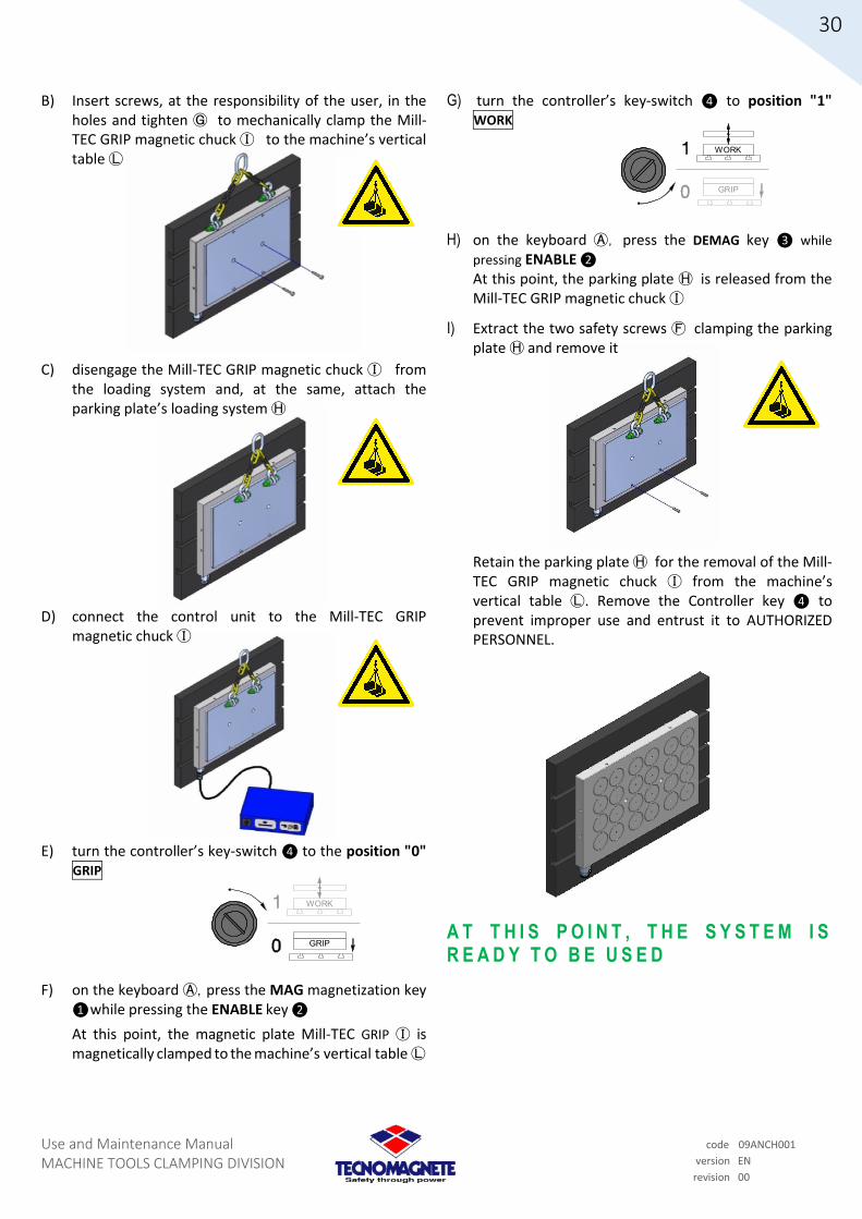
Use and Maintenance Manual MACHINE TOOLS CLAMPING DIVISION
30
code 09ANCH001
version EN
revision 00
GRIP
WORK
GRIP
WORK
B) Insert screws, at the responsibility of the user, in the holes and tighten Ⓖ to mechanically clamp the Mill-TEC GRIP magnetic chuck Ⓘ to the machine’s vertical table Ⓛ
C) disengage the Mill-TEC GRIP magnetic chuck Ⓘ from the loading system and, at the same, attach the parking plate’s loading system Ⓗ
D) connect the control unit to the Mill-TEC GRIP
magnetic chuck Ⓘ
E) turn the controller’s key-switch ❹ to the position "0" GRIP
F) on the keyboard Ⓐ, press the MAG magnetization key ❶ while pressing the ENABLE key ❷
At this point, the magnetic plate Mill-TEC GRIP Ⓘ is magnetically clamped to the machine’s vertical table Ⓛ
G) turn the controller’s key-switch ❹ to position "1" WORK
H) on the keyboard Ⓐ, press the DEMAG key ❸ while
pressing ENABLE ❷ At this point, the parking plate Ⓗ is released from the Mill-TEC GRIP magnetic chuck Ⓘ
I) Extract the two safety screws Ⓕ clamping the parking plate Ⓗ and remove it
Retain the parking plate Ⓗ for the removal of the Mill-TEC GRIP magnetic chuck Ⓘ from the machine’s vertical table Ⓛ. Remove the Controller key ❹ to prevent improper use and entrust it to AUTHORIZED PERSONNEL.
A T T H I S P O I N T , T H E S Y S T E M I S
R E A D Y T O B E U S E D

Use and Maintenance Manual MACHINE TOOLS CLAMPING DIVISION
31
code 09ANCH001
version EN
revision 00
GRIP
WORK
7.3.4 Mill-TEC GRIP on a VERTICAL BASE Removal
W A R N I N G ! This paragraph only concerns the
removal from a vertical base A) ensure that the Mill-TEC GRIP magnetic chuck Ⓘ is
demagnetized and free of processing shards or residues. Position the supporting parking plate Ⓗ so that it fully covers the magnetic surface of the Mill-TEC GRIP magnetic chuck Ⓘ, taking care to align the holes for the clamping screws Ⓖ with the safety screw holes Ⓕ
B) screw the two safety screws Ⓕ to the Mill-TEC GRIP magnetic chuck Ⓘ in order to mechanically clamp the parking plate Ⓗ
C) connect the Control Unit to the Mill-TEC GRIP
magnetic chuck Ⓘ
D) insert the key-switch in the Controller in the selector❹ and turn to the position "0" GRIP
E) on the keyboard Ⓐ press the ❶ MAG magnetization
key while pressing ❷ ENABLE. At this point, the parking plate Ⓗ is clamped to the Mill-TEC GRIP magnetic chuck Ⓘ
F) disengage the parking plate Ⓗ from the loading system and attach the loading system to the Mill-TEC GRIP magnetic chuck Ⓘ
G) on the keyboard Ⓐ press the DEMAG key ❸ and at the same time the ENABLE button ❷. At this point, the Mill-TEC GRIP magnetic chuck Ⓘ is released from the vertical machine table Ⓛ (with this procedure, the parking plate Ⓗ remains magnetically attached to the Mill-TEC GRIP magnetic chuck Ⓘ)
H) disconnect the Control Unit from the Mill-TEC GRIP magnetic chuck Ⓘ
H) remove the two mechanical clamping screws of the Mill-TEC GRIP magnetic chuck Ⓘ from the vertical machine table Ⓛ
A T T H I S P O I N T T H E E Q U I P M E N T
C A N B E R E M O V E D

Use and Maintenance Manual MACHINE TOOLS CLAMPING DIVISION
32
code 09ANCH001
version EN
revision 00
7.4 Mill-TEC GRIP Drilling the
chucks
A) place the Mill-TEC GRIP magnetic chuck Ⓘ with the
parking plate Ⓗ face down and clamped
B) check the area availabe for drilling on the drawing provided by TECNOMAGNETE. Drill holes through the parking plate Ⓗ
C) rotate/return the Mill-TEC GRIP magnetic chuck Ⓘ,
with the parking plate Ⓗ facing upwards
D) use the holes to bore the seats for the screw heads. This operation can be performed without uninstalling the parking plate Ⓗ
E) perform the installation of the Mill TEC-GRIP magnetic chuck as described in sub-sections 7.3.1 and 7.3.3

Use and Maintenance Manual MACHINE TOOLS CLAMPING DIVISION
33
code 09ANCH001
version EN
revision 00
8 RESIDUAL RISK ASSESSMENT
In producing the permanent-electro magnetic systems, TECNOMAGNETE pays great attention to the construction criteria and regulations on safety. Nevertheless, hazardous conditions may remain. This section gives advice on the risks that could arise in certain situations.
8.1 Risks related to the permanent-electro magnet system
By its very nature, the permanent-electro magnetic system can be installed in various applications, but it is vital that the user fully understands and follows both the instructions of this manual and the instructions in the installation manual of the plant on which it is installed. The user must therefore be made aware of any residual risks that could arise during handling and installation.
8.2 Personal protective equipment
The personal protective equipment (PPE) (see also paragraph 1.8) required for the use of permanent-electro magnetic system are the same as required for using the machine on which it is installed (for example, milling machine, grinding machine etc.).
8.3 Exposure to magnetic fields
For any risks associated with exposure to electromagnetic fields, it is recommended to give careful consideration to the possible effects on pregnant women, those with specific diseases, pacemakers or other implants with electronic circuitry, such as acoustic equipment, intracranial metal preparation (or placed close to vital anatomical structures), vascular clips or fragments of ferromagnetic material.
Notice is given therefore that:
1. The permanent-electro magnetic systems produced by TECNOMAGNETE are stationary magnetic systems and, as such, do not emit electric fields
2. The V/m (Volt/meter) emitted during operation is equal to 0 (ZERO)
3. The emission of an electromagnetic field during activation/deactivation does not exceed 100 Gauss at a distance of 100 mm from the magnetic system
It is made clear, therefore that during activation/deactivation, the values of the electromagnetic fields are below the levels given in Table 2 of Annex XXXVI of Legislative Decree 81/2008

Use and Maintenance Manual MACHINE TOOLS CLAMPING DIVISION
34
code 09ANCH001
version EN
revision 00
N S N S N S
9 NORMAL USE OF PERMANENT-ELECTRO MAGNETIC SYSTEM
The basic operating procedure is given below.
9.1 Clamping force
The force of magnetic attraction of TECNOMAGNETE’s permanent-electro magnetic systems is tested and certified. The clamping force is directly proportional to the operative magnetic surface, the type of material to be processed and the conditions of its surface. Workpiece material (mild steel, alloy steel, cast iron ...)
Conditions of the workpiece surface (roughness, flatness ....)
Contact surface of the workpiece (the surface in contact with the poles)
The clamping force is distributed evenly. The magnetic clamping force is always directed towards the surface of the magnetic chuck.
9.2 Cutting force
In any machining, the cutting force is dependent on the operating conditions of the tool (depth, feed rate, RPM) and the hardness of the material being machined. The cutting force exerted by any tool includes a component that makes the workpiece slide on the surface of the magnetic chuck.
The horizontal component originates from the geometry and the rate of feed of the tool. The clamping force must necessarily be greater than the cutting force, which is exerted in all directions, in order to keep the workpiece being machined in place. It is therefore very important that the clamping force, which is exerted perpendicular to the magnetic chuck, is reduced to a fifth when making the calculations in order to counteract the tangential force that would make the workpiece slide.
Example: Cutting force 1000 daN. Clamping force 4000 daN. Clamping force = 4000 daN/5 = 800 daN Therefore: clamping force 800 daN < cutting force 1000 daN (insufficient clamping force).
If mechanical stops are introduced to counter the tangential force, and any slippage of the workpiece being machined on the magnetic chuck, it is clear that the forces in play are altered accableingly:
clamping force 4000 daN > cutting force 1000 daN (sufficient clamping force).
In other words, the introduction of mechanical stops ensures that the tangential component that makes the piece slide is annulled, thereby obtaining extremely safe conditions. The correct positioning of the mechanical stops is very important, especially when the contact surface between the workpiece and the magnetic chuck is limited (this is also true of the clamping force). A mechanical stop can also be used as a point of reference (the machine’s zero point).
clamping force
WORKPIECE
MAGNETIC CHUCK

Use and Maintenance Manual MACHINE TOOLS CLAMPING DIVISION
35
code 09ANCH001
version EN
revision 00
CAUTION: Take care when machining very long pieces with reduced thicknesses because the vectorial moment exerted by the cutting force of the rotating tool can cause the workpiece to rotate.
In this case, two mechanical stops placed on the long side of the piece (against the direction of the rotating tool’s cutting force) will be sufficient. See example 2 of the drawing below.
Another valid alternative is the use of fixed pole extensions that can act as mechanical stops. See example 1.
The fixed pole extensions make use of both mechanical support and magnetic clamping systems (magnetic flux conductors).
9.3 Placing the workpiece for machining on pole extensions
Traditionally, to mill a workpiece and obtain a planar and parallel surface without the aid of an permanent-electro magnetic chuck, shimming operations are carried out on the support surface.
This operation, performed manually, requires long set-up times and skill on the part of the operator in order to obtain a satisfactory result.
With the aid of technology, TECNOMAGNETE’s pole extensions, both fixed and mobile, greatly facilitate and speed up shimming operations.
The pole extensions are designed for automatic, even shimming. The correct use of these accessories enables high tolerances to be obtained to flatness and parallelism from the first milling phase, as well as qualitative improvements in the finishing phase. It also enables a reduction in vibrations due to uneven clamping, which cause tools to wear out prematurely. The steps for positioning of the pole extensions and the operating principle are as follows:
1- A plane must be created by placing three fixed points (using the Fixed pole extensions) in order to obtain a working surface (the principle by which a plane passes through three points).
CAUTION: The holes in the poles of the permanent-electro magnetic chucks have been specifically designed for placing pole extensions. These accessories, specifically acting as magnetic flux conductors, do not require the screws to be excessively tightened.
Recommended torque wrench setting M = 15 Nm
Maximum torque wrench setting, M = 23 Nm
It is also recommended to mill the Fixed pole extensions in order to obtain a flat, parallel support surface for the permanent-electro magnetic chuck.
2- The remaining surface (support bed of the workpiece to be machined) must be covered by Mobile pole extensions that will adapt to the surface irregularities of the workpiece, as well as continuity of the passage of magnetic flux between the permanent-electro magnetic chuck and the workpiece. It is very important to deploy the greatest possible number of mobile pole extensions since their quantity determines the clamping force exerted on the workpiece.
example 1 example 2
MECHANIC
AL STOPS
Tool feed

Use and Maintenance Manual MACHINE TOOLS CLAMPING DIVISION
36
code 09ANCH001
version EN
revision 00
3- Place the workpiece on the bed of pole extensions.
4- On starting a Magnetization cycle on the permanent-electro magnetic chuck, the mobile pole extensions will observed adapting to the contour of the workpiece. At this point, initiate machining on the upper surface.
5- After the first machining, initiate a Demagnetization cycle.
6- Turn the workpiece over so the machined side rests on the bed of pole extensions. Initiate a magnetization cycle and, at this point, initiate the second machining.
7- After the second machining, a Demagnetization cycle can be initiated in order to remove the workpiece.
CAUTION: When using pole extensions (Milling series), ensure the entire surface of the workpiece is covered by the pole extensions.
F = Fixed pole extensions
M = Mobile pole extensions
The clamping force is directly proportional to the surface in contact with the workpiece (and therefore to the number of pole extensions). The higher the number, the greater the clamping force. Check the correct positioning of the pole extensions, ensuring a magnetic balance (the number of poles with extensions housed on the SOUTH polarity corresponds to the number of poles with extensions housed on the NORTH polarity). In other words, should it not be possible for any reason to use the whole surface of the workpiece for magnetic clamping with the aid of pole extensions, make sure those present comply with the following:
A - the number of pole extensions housed on the North (N) polarity is equal to the number of pole extensions housed on the South (S) polarity (it is generally sufficient to ensure the extensions face each other since the checkerboard layout of the poles provides alternation between South and North).
B - place the polar extensions that will contact with the workpiece on its entire perimeter, as far as possible. This ensures a better clamping force to counteract the cutting force.
C - for mobile polar extensions with a square layout only, the correct use of a shimming system is important. Indeed, the correct positioning of the mobile polar extensions with a square layout must necessarily be in opposition.
When moving vertically, the moving parts of the pole extensions must only move away or closer. Their movement must never be simultaneous and parallel (this measure is not necessary with the rounded mobile pole extensions).
PROPER DISPOSAL
IMPROPER DISPOSAL
PROPER DISPOSAL
IMPROPER DISPOSAL
PROPER DISPOSAL

Use and Maintenance Manual MACHINE TOOLS CLAMPING DIVISION
37
code 09ANCH001
version EN
revision 00
9.4 How to calculate the clamping force
The magnetic clamping force is very easy to calculate and depends on:
the surface of the magnetic chuck in contact with the workpiece to be clamped
the conditions of the surfaces in contact with the workpiece to be clamped
technical specifications of the material of which the workpiece is made
model of the magnetic chuck used
9.5 Example of magnetic chuck clamping force calculation
a = Model of magnetic chuck: Mill Tec GRIP in the calculation a value of 40 will be used (cm² per pole) (see paragraph 3.3)
b = n° of operative poles 10 (it’s an example of number of poles used/covered by the workpiece)
c = value of magnetic force concentrated and constand over time: in the best conditions is 16 daN/cm² (see section 3.4)
d = Roughness: Milling 0,7 (corrsponding to the percentage value of 70%)
e = Mild steel: value is 1 (see section 3.3.3)
Give the foregoing, the clamping force is calculated with the following formula:
Total clamping force = a x b x c x d x e
or rather:
Total clamping force = 40 x 10 x 16 x 0,7 x 1 = 4700 da/N
Since this is a purely theoretical calculation, it cannot, of course, take into account all the variables that arise during machining (uneven material with some areas harder than others, surface distortions that prevent perfect contact between the workpiece and the extensions, a surface that does not allow even removal by wiping, etc.), a safety factor (Fa) of 0,5 is recommended:
therefore, with reference to the example of the previous calculation:
Total clamping force with Fa = 4700 x 0,5 = 2350 da/N
9.6 Clamping rules for conventional machining
In the following sub-sections, some examples of conventional machining are analyzed.
9.6.1 Face milling: Direct clamping to the permanent-electro magnetic chuck
A typical process that can be performed on an permanent-electro magnetic chuck is the face milling of plates. After removing any fouling and burrs, which can increase the air gap and therefore the clamping force (see Chapter 3), position the workpiece and carry out manual shimming.
This is to limit any distortion due to the force of the system’s magnetic attraction any vibrations caused by the machining.
This type of machining has the sole advantage of placing the workpiece directly on to the magnetic chuck, but presents the disadvantage of not allowing processes such as contouring, drilling and through machining in general, and the flatness obtained will depend on the skill of the operator.

Use and Maintenance Manual MACHINE TOOLS CLAMPING DIVISION
38
code 09ANCH001
version EN
revision 00
9.6.2 Face milling: Clamping on pole extensions
To obtain further advantages from the permanent-electro magnetic system, such as an optimal flatness of the machined workpiece, TECNOMAGNETE can also provide both Fixed and Mobile pole extensions (see the models in section 4.1).
The steps required to position pole extensions and the operating principle are described in section 9.3. The mechanical machining first involves the roughing and contouring of both faces of the workpiece, then a demagnetization cycle of the permanent-electro magnetic chuck. The plate (the machined workpiece), distorted due to yield and overheating of the material, is released from internal stresses and takes a new position. At this point, perform a new magnetization cycle of the permanent-electro magnetic chuck so that the mobile pole extensions readjust to the surfaces in contact with the plate, and perform the finishing of the upper face. The last step is a demagnetization cycle of the permanent-electro magnetic chuck, then turning the plate over and replacing it with the finished face on the bed of extensions. At this point, the finishing of the plate’s other face can be performed.
9.6.3 Through machining operations: clamping on pole extensions
To perform through machining, it is indispensable to raise the workpiece above the base to enable the tool to pierce the workpiece without damaging the surface of the permanent-electro magnetic chuck. Among the accessories supplied by TECNOMAGNETE are Fixed and Mobile pole extensions (see the models in section 4.1) that have been designed to ensure optimum circulation of magnetic flux and obtain magnetic clamping. The steps for positioning of pole extensions and the operating principle are described in section 9.3.
9.6.4 Machining cylindrical workpieces
For the machining of cylindrical workpieces, or in any case when the supporting surface is not flat, the workpiece should be placed directly on the permanent-electro magnetic chuck, in addition to the aid of fixed pole extensions, in order to create a support with more points of magnetic clamping. As well as stopping the workpiece rolling, this acts as a magnetic flux conductor and therefore a clamp. To machine the workpiece, ensure the components of the machining cutting force are directed towards the extension.
Fixed pole extension
Cylinder to be machined

Use and Maintenance Manual MACHINE TOOLS CLAMPING DIVISION
39
code 09ANCH001
version EN
revision 00
9.6.5 Machining parts in series
For the machining of parts in series or with irregular shapes, we recommend the use of pole extensions or the use of top plates. To use top plates, make pole extensions of diameters equal to the diameter of the poles and combine them with non-magnetic material (stainless steel, aluminum, etc.). It is recommended to respect the pole pitch of the permanent-electro magnetic chuck, both regarding the size of the polar extension, which must the same as the poles, and regarding the spaces between the poles. At this point, shape the top plate in order to make a workpiece positioning mask. The entire frame of the permanent-electro magnetic chuck surrounding the magnetic islands (with the sole exception of the area of the discharge cable connection) can be drilled to insert pegs to aid positioning and removal. The magnetic chuck can also be used for clamping vices, dividers and jigs for clamping material that is particularly difficult to clamp or non-magnetic material.
9.7 Machining examples
Figure 9.7A - Face milling, drilling, running tracks Figure 9.7B – Curtain facing and execution of key seats
Figure 9.7C - Roughing first face Figure 9.7D – Turning over, roughing, stress release and finishing second face Figure 9.7E - Flattening and butting profiles
Figure 9.7F - Butting and tubular drilling

Use and Maintenance Manual MACHINE TOOLS CLAMPING DIVISION
40
code 09ANCH001
version EN
revision 00
Figure 9.7G - Blade profiling and sheet metal chamfering Figure 9.7H - Multiple coupled guides profiling Figure 9.7I - Flattening and contouring details on cast and moulded metals
Figure 9.7L - Flattening, contouring and boring details in cast steel Figure 9.7M - Three-dimensional machining Figure 9.7N - Machining plates with horizontal axis

Use and Maintenance Manual MACHINE TOOLS CLAMPING DIVISION
41
code 09ANCH001
version EN
revision 00
10 MAINTENANCE Adequate maintenance is vital to maximise equipment duration under operating conditions and for optimal yield, as well as operational safety over time.
10.1 Safety rules during maintenance
THE OPERATIONS MUST BE CARRIED OUT ONLY BY TRAINED PERSONNEL
The main precautions to be taken during maintenance operations are: all maintenance work should be performed with
equipment turned off and, where possible, disconnected from the mains supply
repairs of electrical equipment must be carried out in the absence of voltage and with the emergency button activated. Operational, maintenance and cleaning personnel etc. must strictly comply with the safety rules in force in the country of operation
always wear protective gloves and safety shoes, as well as any other personal protective equipment and clothing that covers body parts as much as possible, where required
do not wear rings, watches, chains, bracelets, loose clothing etc. during maintenance operations
place an insulating rubber mat under the feet (where possible) when performing maintenance
avoid operating on a wet floor or in a humid environment
comply with the maintenance schedule components must only be replaced with original spare
parts in order to ensure perfect operation during machine cleaning, take care not to use grinding
wheels, abrasives, corrosives or solvents that could remove or make unreadable numbers, abbreviations, and information placed on the equipment
never allow electrical and electronic equipment to become wet
only use a vacuum cleaner on electrical parts, no compressed air.
10.2 Daily maintenance This can be performed by the operator or emergency personnel at the end of the day’s production: general cleaning of equipment check the mobile/fixed connectors are operating
correctly, where they form part of the permanent-electro magnetic system (pay particular attention to any blackened/scorched areas suggesting an electrical problem)
10.3 Weekly maintenance This is performed by the operator at the end of the weekly production: check of lamps and LED indicators (see chapter 6) check of buttons/keys (see chapter 6).
10.4 Monthly maintenance This is performed by qualified, skilled operators every month, if the work is routinely carried out in daily shifts of 8 to 10 hours: visual inspection of the surfaces and the general state
of the permanent-electro magnetic chucks check the tightness of the screws of permanent-electro
magnetic chucks elimination of any uneven edges and roughness inspect and check the tightness of the Control Unit
screws of the (particular attention should be paid to tightening the terminal screws)
check that there is no leakage of liquid (water, coolant, machining oil etc. for processing) in all Control Unit components (particular attention should be paid to the connectors and junction boxes)
check structural work of the enclosures, boxes, cabinets, etc.
10.5 Six-monthly maintenance This is performed by trained, skilled operators every six months if the work is routinely carried out in daily shifts of 8 to 10 hours: check for cable slippage throughout the whole
permanent-electro magnetic system check the continuity of earth conductors and protection measure the resistance values and insulation at 500V pass a piece of steel across the surface of the
demagnetised permanent-electro magnetic chucks to detect any significant residual magnetic halos
10.6 Extraordinary maintenance Maintenance operations not described in this manual are considered to be extraordinary maintenance and must be performed by skilled personnel identified by TECNOMAGNETE S.p.A.

Use and Maintenance Manual MACHINE TOOLS CLAMPING DIVISION
42
code 09ANCH001
version EN
revision 00
10.7 Information for repairs and extraordinary maintenance operations
In order to quickly find any faults, TECNOMAGNETE, on completion of the permanent-electro magnet system, supplies: dimensional layout and assembly instructions specifications of the model of permanent-electro
magnetic chuck and Control Unit circuit diagrams TECNOMAGNETE S.p.A. is at the disposal of customers for any requirements and to clarify any doubts about the operation and maintenance of the permanent-electro magnetic system.
11 PROBLEMS AND THEIR SOLUTIONS
The purpose of this section is to aid the operator in identifying and resolving problems that may arise during the use of the permanent-electro magnetic system. Repairs to electrical equipment must be carried out in the absence of voltage and with the emergency button activated. Personnel assigned to repairs must strictly observe the safety rules in force in the country of use.
11.1 Problems Avoid problems in calculating forces by referring to the specific sections, taking account of the safety factors to be included in the calculations. Take care always to check that the machining forces do not exceed those of the clamping, in certain situations. To remedy electrical faults, refer both to the circuit diagrams attached to the electro-permanent magnetic system and the Control Unit’s Use and Maintenance Manual provided. Repairs to electrical equipment must be carried out in the absence of voltage and with the emergency button activated.
ALL CHANGES TO THE ORIGINAL WIRING OF THE PERMANENT-ELECTRO MAGNETIC SYSTEM MUST BE
CARRIED OUT ONLY BY THE PERSONNEL OF THE TECHNICAL ASSISTANCE SERVICE OR THROUGH SPECIFICATIONS SENT
BY TECNOMAGNETE’S TECHNICAL ASSISTANCE SERVICE
CAUTION: As stated previously in Chapter 6, should the Control Unit include removable connectors, once the discharge cable with flying connection, it is mandatory to insert the cap provided on the panel connector in order to prevent penetration by liquids or various machining residues.
Problem Remedy
The controller does not start
Check the supply voltage and frequency are suitable and correct (the power supply must be sufficient for both the control unit and the magnetic chuck)
On starting, the system enters
the ALARM state
Check that the DB9 key has been inserted properly (see section 5.6)
Check the DB9 key has been correctly inserted for the Control Unit using the PLC interface keyboard (see section 6.4.7) If the keyboard has been replaced with a new one, the SET-UP procedure must be repeated (see ST200 Manual)
Check that the keyboard is properly connected to the Controller
The Control Unit does not perform the MAG cycle
Check the ENABLE button was pressed together with the MAG button
Ensure the correct keys are pressed for at least 500 ms (half a second)
Check the DB9 key has been inserted correctly (see section 5.6)
Check the DB9 plug for the control unit that uses the PLC interface keyboard has been inserted correctly (see section 6.4.7)
The Control Unit does not
perform the DEMAG cycle
Make sure the ENABLE key is pressed together with the DEMAG key Ensure the correct keys are pressed for at least 500 ms (half a second) Check the DB9 key has been inserted correctly (see section 5.6) Check the DB9 plug for the control unit that uses the PLC interface keyboard has been inserted correctly (see section 6.4.7)
The Control Unit attempts to perform a
MAG cycle, but remains in
ALARM state
Check the power supply, as with cases when the controller will not turn on Check the correct wiring and correct connection of the discharge cables Perform a DEMAG cycle (which should reset the Control Unit) before repeating a MAG cycle
The Control Unit demagnetizes the magnetic
chuck (and vice versa) during
performance of the MAG cycle
Check the correct wiring of the discharge cables and any cabling between the controller and the electro-permanent magnetic chuck through an intermediate junction
Any malfunction of the Unit Control must, in any event, be reported to the TECNOMAGNETE Technical Assistance Service.

Use and Maintenance Manual MACHINE TOOLS CLAMPING DIVISION
43
code 09ANCH001
version EN
revision 00
A
C
D
C E
B B
12 DECOMMISSIONING AND DISPOSAL
12.1 Decommissioning
Should it be decided not to use the permanent-electro magnetic system any more, it is advisable to disconnect it from the power supply and to make it inoperative by removing it from the machine on which it is installed, also removing the controller and any moving parts.
12.2 Disposal
In accableance with EU Directives, or the laws in force in the country of use, the user must arrange the destruction, disposal and elimination of the various materials that make up the equipment. In the case of equipment destruction, safety precautions must be taken to avoid risks associated with the decommissioning of industrial machinery, paying particular attention to the following: dismantling equipment in the installation area carriage and handling of the equipment dismantling the equipment separation of the various materials that make up the
equipment To carry out the destruction and disposal of the permanent-electro magnetic system, some basic rules designed to safeguard health and the environment must be observed, paying particular attention to the separation, recycling or disposal of materials, always referring to the National or Regional laws in force on the disposal of industrial solid waste and toxic and harmful waste. Sheaths, flexible ducts and plastic or non-metallic elements in general must be dismantled and disposed of separately.
Electrical components such as circuit breakers, transformers, sockets etc. must be dismantled for reuse, if in good condition, or reconditioning and recycling.
13 SPARE PARTS
All permanent-electro magnetic systems come with a parts list together with the other product documentation (see section 16 Attachments).
ALL OPERATIONS TO REPLACE OR EXCHANGE PARTS OF
THE CONTROL UNIT SHOULD BE HANDLED BY TECNOMAGNETE’S TECHNICAL ASSISTANCE SERVICE
13.1 Spare controller and permanent-electro magnetic chucks
In the event the permanent-electro magnetic chucks or the Controller are replaced/exchanged, it is vital to contact TECNOMAGNETE’s Technical Assistance Service to ensure the equipment is replaced with a suitable product with adequate performance and specifications.
13.2 Adaptors per connectors 7PIN – 10PIN – 5PIN
Special adaptors are available on request to be installed on the permanent-electro magnetic chuck, to let it compatible in presence of ERGON 5PIN connector on discharge cable.
Descrizione / Description Tipologia / Type Connettore Connector
A 10PIN M.P. Ergon
Adattatore Adaptor
B Simbolo indicativo Indicative symbol
Connettore Connector
C 5PIN F.V. Ergon
Connettore Connector
D 7PIN M.P. HML or REC
Connettore Connector
E 10PIN F.V. Ergon

Use and Maintenance Manual MACHINE TOOLS CLAMPING DIVISION
44
code 09ANCH001
version EN
revision 00
PATENTED SYSTEM MADE IN ITALY
ON
OFF
CH 4
CH 3
J1
J2
J3
MASTER
PLC MASTERSERIAL IN
PLC CH ENABLE
CH ENABLE
SERIAL OUT
KEY LOCK
MAIN SUPPLY CH 1
CH 2
Master connection to J1ASS.
TENSIONE/FASE/FREQUENZA
Via Nerviano , 31 - La ina te (Milano) - Made in ITALY
CODICE
CICLO SETT. PROD.
N° SERIE
PESO
DIMENSIONI
DB9 key lock
connection to J3
PATENTED SYS TEM M ADE IN ITALY
PATENTED SYSTEM MADE IN ITALY
ON
OFF
PATENTED SYSTEM MADE IN ITALY
ON
OFF
PATENTED SYSTEM MADE IN ITALY
ON
OFF
PATENTED SYSTEM MADE IN ITALY
PATENTED SYSTEM MADE IN ITALY
ON
OFF
PATENTED SYSTEM MADE IN ITALY
ON
OFF
13.3 Spare keyboards (only applicable for
remote control panels)
In the event the ALARM LEDs illuminate (after replacing/changing the only remote keyboard) a SET-UP procedure must be performed to enable the reconfiguration of the keyboard with the remaining components of the Control Unit.
The SET-UP procedure is as follows:
a) TURN OFF the Controller
b) replace the remote control (included keyboard) with the new one, connecting it in exactly the same position on the Controller
EXAMPLE
ST200 rear view/bottom side
c) Simultaneously press the MAG, ENABLE and DEMAG keys, then (while holding down the three keys) turn on the Controller
d) still pressing the keys as instructed in step c), wait a few seconds until all the cycle LEDs flash (except the ALARM led)
e) release the MAG, ENABLE and DEMAG keys, then turn off the Controller within 10 seconds
f) turn on the Controller and automatically all the LEDs will flash
g) turn off the Controller (it is suggested to turn off within five seconds)
h) at this point, turn the Controller back on and the Control Unit will be operational.
CAUTION: IF, DURING STEP h), THE ALARM LEDS ARE ILLUMINATED, THIS MEANS THE KEYBOARD’S INTERNAL ELECTRONICS ARE NOT CONFIGURED CORRECTLY. CONTACT TECNOMAGNETE’S TECHNICAL ASSISTANCE SERVICE AND REPORT THE ANOMALY.

Use and Maintenance Manual MACHINE TOOLS CLAMPING DIVISION
45
code 09ANCH001
version EN
revision 00
14 WARRANTY AND ASSISTANCE
14.1 Warranty conditions
The permanent-electro magnetic systems produced by TECNOMAGNETE are guaranteed for a period of 24 months from the date of invoice, unless otherwise agreed. The warranty covers all material and manufacturing defects, and provides for the replacement of parts or the repair of defective parts solely by and/or at the premises of TECNOMAGNETE. Products must be sent for repair by the client CARRIAGE PAID. Once repaired, products will be returned to the customer CARRIAGE FORWARD. The warranty does not envisage either the intervention of the workers or employees of TECNOMAGNETE at the installation site, or the dismantling of TECNOMAGNETE products from the plant. Should TECNOMAGNETE send a member of staff for practical reasons, the labour will be invoiced at current rate plus any transfer and travel expenses. Under no circumstances does the warranty give the right to indemnity for any direct or indirect damage caused to persons or property or for repairs made by the buyer or third parties. Repairs carried out under warranty do not alter its duration. The following are excluded from the warranty:
damage resulting from normal wear and tear from use faults caused by incorrect use or installation damage caused by the use of spare parts other than
those recommended damage caused by fouling
14.2 Invalidity of warranty
The warranty does not apply in the following cases:
non-payment or other breach of contract changes made without TECNOMAGNETE’s consent when the serial number has been tampered with or
deleted when the damage is caused by:
improper operation or misuse mistreatment impacts or other causes not attributable to the
normal conditions of operation and/or use if dismantled, tampered with or repaired without the
authorisation of TECNOMAGNETE S.p.A. if used in hazardous areas where adequate safety
systems have not been installed with fixed and mobile protection with additional interconnected alert devices
For any dispute, the Court of Milan has jurisdiction. For any problem or information, contact the Technical Assistance Service at the following address:

Use and Maintenance Manual MACHINE TOOLS CLAMPING DIVISION
46
code 09ANCH001
version EN
revision 00
15 TECNOMAGNETE SERVICE NETWORK
HEADQUARTERS TECNOMAGNETE S.p.A. Via Nerviano, 31 20020 Lainate - Italy Tel. +39 02937591 Fax +39 0293759212 [email protected] Company with certified quality system FRANCE - BENELUX - SWITZERLAND FRENCH TECNOMAGNETE SARL 52 Av. S. Exupéry 01200 Bellegarde sur Valserine Tel. +33450560600 (FRANCE) +33450560610 fax [email protected] GERMANY - AUSTRIA GERMAN-Switzerland TECNOMAGNETE GmbH 4 Ohmstraße 63225 Langen (GERMANY) Tel. +49 6103 750730 Fax +49 6103 7507311 [email protected] USA - CANADA - MEXICO TECNOMAGNETE Inc. 6655 Allar Drive, Sterling Hts, MI 48312 Tel .: +1 586 276 6001 Fax: +1 586 276 6003 [email protected] CHINA TECNOMAGNETE Shanghai Liaison Office Tel. +86 21 6888 2110 [email protected]
The information on authorized Service Centers can be found by visiting the website: www.tecnomagnete.com
and accessing the menu CONTACT/Sales networks and branches
16 ATTACHMENTS
“Attachments" means certificates, technical drawings, spare parts, etc. These are, if necessary, added to this Use and maintenance manual for further information.
16.1 Declaration of conformity
The EC declaration of conformity can be consulted and downloaded in pdf format via the website: www.tecnomagnete.com/engcecertificate.htm