machining level - iii
TRANSCRIPT

Ethiopian TVET
Program STEP-GIZ
CT program for Remote Teaching Title: Machining L-3
Perform Advanced lathe CNC Operations
July 2020 Page 1 of 100
MACHINING
Level - III
Learning Guide 3
Unit of Competence: Perform Advanced lathe
CNC Operations
Module Title: Performing Advanced lathe CNC
Operations
LG Code: IND MAC3 03 0217

Ethiopian TVET
Program STEP-GIZ
CT program for Remote Teaching Title: Machining L-3
Perform Advanced lathe CNC Operations
July 2020 Page 2 of 100
Instruction Sheet Learning Guide #1
This learning guide is developed to provide you the necessary information regarding the following
content coverage and topics:
1. Determine job requirements
2. Prepare CNC lathe machining process / Write program
3. Perform appropriate Lathe operations
This guide will also assist you to attain the learning outcome stated in the cover page. Specifically,
upon completion of this Learning Guide, you will be able to:
• Cutting tools, instruments and machine accessories are selected according to the
requirements of the operation.
• Cutting speed and feeds rate are calculated based on work- piece and cutting tool
material specifications
• written in standard CNC lathe operations, code format and in accordance with standard
operating procedures.
• CNC lathe operations are performed to produce component according to drawing
specifications.
Learning Instructions:
1. Read the specific objectives of this Learning Guide.
2. Follow the instructions described below 3 to 100.
3. Read the information written in the information “Sheet.
4. Accomplish the “Self-check test.
5. Do the “LAP test”.

Ethiopian TVET
Program STEP-GIZ
CT program for Remote Teaching Title: Machining L-3
Perform Advanced lathe CNC Operations
July 2020 Page 3 of 100
Determine job requirements
Introduction:
In CNC Milling Machining, operator or machinist must have to understand the
drawing, interpret and analyze it as a reference to produce program manual script
prior to manufacture the part. The following are guide before machining a part:
1. Drawings need to be interpreted to produce component as per specifications.
2. The sequence of operation should be established as well to determine what
steps in producing the component according to specification.
3. Cutting tools are selected according to the requirements of the operation.
4. Cutting speed and feed rate calculated based on work- piece and cutting tool
material.
5. Process / job adjustment sheets are filled up with relevant machine, tool and
raw material data.

Ethiopian TVET
Program STEP-GIZ
CT program for Remote Teaching Title: Machining L-3
Perform Advanced lathe CNC Operations
July 2020 Page 4 of 100
CNC Programming
To operate CNC machine tool, the first step is to understand the part drawing
and produce a program manual script. The procedure for machining a part is as
follows
1) Read drawing
2) Produce the program manual script
3) Input the program manual script by using the machine control panel
4) Manufacture a part
1. Read drawing
X
Φ60 Φ40 Ζ
40
150
2. Produce the program manual script
N1 T0106 N2 M03 S460 N3 G00 X90Z20
N4 G00 X31Z3 N5 G01 Z-50 F100 N6 G00 X36
N7 Z3
…
3. Input the program manual script

Ethiopian TVET
Program STEP-GIZ
CT program for Remote Teaching Title: Machining L-3
Perform Advanced lathe CNC Operations
July 2020 Page 5 of 100
4. Manufacture a part
X
Z
Figure 1.1 The workflow of operation of CNC machine tool
Interpolation Interpolation refers to an operation in which the machine tool moves along the
workpiece parts. There are five methods of interpolation: linear, circular, helical,
parabolic, and cubic. Most CNC machine can provide linear interpolation and
circular interpolation. The other three methods of interpolation (helical, parabolic,
and cubic interpolation) are usually used to manufacture the complex shapes, such
as aerospace parts. In this manual, linear and circular interpolation are introduced.
Linear Interpolation There are two kinds of linear interpolation:
1) Tool movement along a straight line X
Z
Figure 1.2 Linear Interpolation (1)

Ethiopian TVET
Program STEP-GIZ
CT program for Remote Teaching Title: Machining L-3
Perform Advanced lathe CNC Operations
July 2020 Page 6 of 100
2) Tool movement along the taper line
X
Z
Figure 1.3 Linear Interpolation (2)
Circular Interpolation Figure 1.4 shows a tool movement along an arc.
X
Z
Figure 1.4 Circular Interpolation Note:
In this manual, it is assumed that tools are moved against workpieces.
Ethiopian TVET
Program STEP-GIZ
CT program for Remote Teaching Title: Machining L-3
Perform Advanced lathe CNC Operations
July 2020 Page 7 of 100
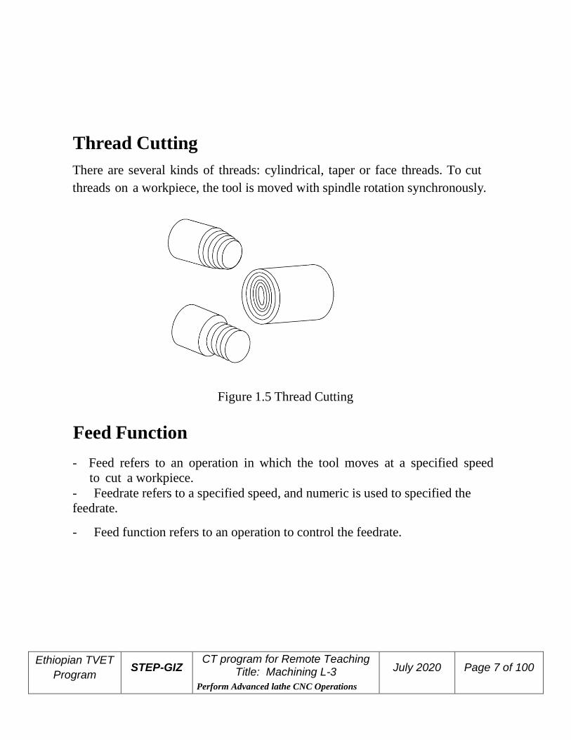
Thread Cutting
There are several kinds of threads: cylindrical, taper or face threads. To cut
threads on a workpiece, the tool is moved with spindle rotation synchronously.
Figure 1.5 Thread Cutting
Feed Function - Feed refers to an operation in which the tool moves at a specified speed
to cut a workpiece.
- Feedrate refers to a specified speed, and numeric is used to specified the
feedrate.
- Feed function refers to an operation to control the feedrate.

Ethiopian TVET
Program STEP-GIZ
CT program for Remote Teaching Title: Machining L-3
Perform Advanced lathe CNC Operations
July 2020 Page 8 of 100
For example:
F2.0 //feed the tool 2mm, while the workpiece makes one turn
Coordinate System
Reference Point Reference point is a fixed position on CNC machine tool, which is determined
by cams and measuring system. Generally, it is used when the tool is required
to exchange or the coordinate system is required to set.
There are two ways to move to the reference point:
- Manual reference position return: The tool is moved to the reference point by
operating the button on the machine control panel. It is only used when the
machine is turned on.
- Automatic reference position return: It is used after the manual reference
position return has been used. In this manual, this would be introduced.

Ethiopian TVET
Program STEP-GIZ
CT program for Remote Teaching Title: Machining L-3
Perform Advanced lathe CNC Operations
July 2020 Page 9 of 100
Machine Coordinate System The coordinate system is set on a CNC machine tool. Figure 1.8 is a machine
coordinate system of turning machine, and shows the direction of axes:
In general, three basic linear coordinate axes of motion are X, Y, Z. Moreover, X,
Y, Z axis of rotation is named as A, B, C correspondently. Due to different types
of turning machine, the axis direction can be decided by following the rule –
“three finger rule” of the right hand.

Ethiopian TVET
Program STEP-GIZ
CT program for Remote Teaching Title: Machining L-3
Perform Advanced lathe CNC Operations
July 2020 Page 10 of 100
- The thumb points the X axis. X axis controls the cross motion of the
cutting tool. “+X” means that the tool is away from the spindle centerline
- The index points the Y axis. Y axis is usually a virtual axis.
- The middle finger points the Z axis. Z axis controls the motion of the
cutting tool. “+Z” means that the tool is away from the spindle.
Workpiece Coordinate System
The coordinate system is set on a workpiece. The data in the NC program is
from the workpiece coordinate system.
Example: Those four points can be defined on workpiece coordinate
system:
Ethiopian TVET
Program STEP-GIZ
CT program for Remote Teaching Title: Machining L-3
Perform Advanced lathe CNC Operations
July 2020 Page 11 of 100
P1 corresponds to X25 Z-7.5
P2 corresponds to X40 Z-15
P3 corresponds to X40 Z-25
P4 corresponds to X60 Z-35
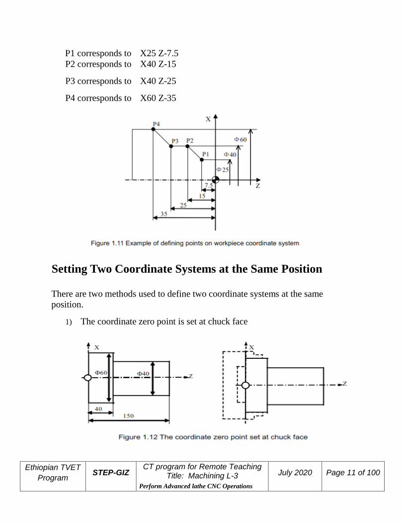
Setting Two Coordinate Systems at the Same Position There are two methods used to define two coordinate systems at the same
position.
1) The coordinate zero point is set at chuck face

Ethiopian TVET
Program STEP-GIZ
CT program for Remote Teaching Title: Machining L-3
Perform Advanced lathe CNC Operations
July 2020 Page 12 of 100
2) The coordinate zero point is set at the end face of workpiece
Absolute Commands The absolute dimension describes a point at “the distance from zero point of the
coordinate system”.
Example: These four point in absolute dimensions are the
following:
P1 corresponds to X25 Z-7.5
P2 corresponds to X40 Z-15
P3 corresponds to X40 Z-25
P4 corresponds to X60 Z-35
Ethiopian TVET
Program STEP-GIZ
CT program for Remote Teaching Title: Machining L-3
Perform Advanced lathe CNC Operations
July 2020 Page 13 of 100
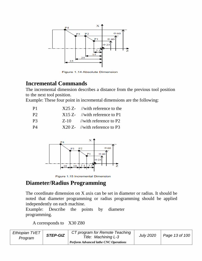
Incremental Commands The incremental dimension describes a distance from the previous tool position
to the next tool position.
Example: These four point in incremental dimensions are the following:
P1
corresponds to X25 Z-
7.5 //with reference to the
zero point P2
corresponds to X15 Z-
7.5 //with reference to P1
P3
corresponds to Z-10 //with reference to P2
P4
corresponds to X20 Z-
10 //with reference to P3
Diameter/Radius Programming The coordinate dimension on X axis can be set in diameter or radius. It should be
noted that diameter programming or radius programming should be applied
independently on each machine.
Example: Describe the points by diameter
programming.
A corresponds to X30 Z80

Ethiopian TVET
Program STEP-GIZ
CT program for Remote Teaching Title: Machining L-3
Perform Advanced lathe CNC Operations
July 2020 Page 14 of 100
B corresponds to X40 Z60
Example: Describe the points by radius programming.
A corresponds to X15 Z80
B corresponds to X20 Z60
Spindle Speed Function
The cutting speed (v) refers to the speed of the tool with respect to the workpiece
when the workpiece is cut. The unit of the cutting speed is m/min. As for the
CNC, the cutting speed can be specified by the spindle speed (N) in min-1.

Ethiopian TVET
Program STEP-GIZ
CT program for Remote Teaching Title: Machining L-3
Perform Advanced lathe CNC Operations
July 2020 Page 15 of 100
Tool Function
Tool Selection

Ethiopian TVET
Program STEP-GIZ
CT program for Remote Teaching Title: Machining L-3
Perform Advanced lathe CNC Operations
July 2020 Page 16 of 100
It is necessary to select a suitable tool when drilling, tapping, boring or the like is
performed. As it is shown in Figure 1.19, a number is assigned to each tool. Then
this number is used in the program to specify that the corresponding tool is
selected.
Tool Offset When writing a program, the operator just use the workpiece dimensions according
to the dimensions in the part drawing. The tool nose radius center, the tool
direction of the turning tool, and the tool length are not taken into account.
However, when machining a workpiece, the tool path is affected by the tool
geometry.
Tool Length Compensation There are two kind of ways to specify the value of tool length compensation. ➢ Absolute value of tool length compensation (the distance between tool tip
and machine reference point)

Ethiopian TVET
Program STEP-GIZ
CT program for Remote Teaching Title: Machining L-3
Perform Advanced lathe CNC Operations
July 2020 Page 17 of 100
➢ Incremental value of tool length compensation (the distance between tool tip
and the standard tool) As it is shown in Figure 1.21, L1 is the tool length on X axis. L2 is the tool length
on Z axis. It should be noted that the tool wear values on X axis or Z axis are also
contained in the tool length compensation.
Tool Radius Compensation
Figure 1.22 shows the imaginary tool nose as a start position when writing a program.
Miscellaneous Function

Ethiopian TVET
Program STEP-GIZ
CT program for Remote Teaching Title: Machining L-3
Perform Advanced lathe CNC Operations
July 2020 Page 18 of 100
Miscellaneous function refers to the operation to control the spindle, feed, and
coolant. In general, it is specified by an M code.
When a move command and M code are specified in the same block, there are
two ways to execute these commands:
1) Pre-M function
M command is executed before the completion of move
command
2) Post-M function
M command is executed after the completion of move command.
The sequence of the execution depends on the specification of the machine tool
builder.
Program Configuration Structure of an NC Program
As it is shown in Figure 1.25, an NC program consists of a sequence of NC
blocks. Each block is one of machining steps. Commands in each block are the
instruction.
➢ Format of program name
The program name must be specified in the format OXXXX (X could be
letters or numbers).
➢ Format of program number
The program number should be started with %XXXX or OXXXX (X could
be numbers only).
➢ Format of blocks
A block starts with the program block number.

Ethiopian TVET
Program STEP-GIZ
CT program for Remote Teaching Title: Machining L-3
Perform Advanced lathe CNC Operations
July 2020 Page 19 of 100
➢ Format of end of program
The last block should contain M02 or M03 to indicate the end of program.
➢ Format of Comments
All information after the “;” is regarded as comments.
All information between “( )” is regarded as comments.
Main Program and Subprogram
There are two type of program: main program and subprogram. The CNC operates
according to the main program. When a execution command of subprogram is at the execution
line of the main program, the subprogram is called. When the execution of subprogram is
finished, the system returns control to the main program.
Note:
Main program and its subprogram must be written in a same file with a different program

Ethiopian TVET
Program STEP-GIZ
CT program for Remote Teaching Title: Machining L-3
Perform Advanced lathe CNC Operations
July 2020 Page 20 of 100
codes.
Preparatory Function (G code)
There are two types of G code: one-shot G code, and modal G code.
G code List The following table is the list of G code in HNC system.

Ethiopian TVET
Program STEP-GIZ
CT program for Remote Teaching Title: Machining L-3
Perform Advanced lathe CNC Operations
July 2020 Page 21 of 100

Ethiopian TVET
Program STEP-GIZ
CT program for Remote Teaching Title: Machining L-3
Perform Advanced lathe CNC Operations
July 2020 Page 22 of 100
Explanation:
1) G codes in 00 group are one-shot G code, while the other groups are
modal G code.
2) ◣ means that it is default setting.

Ethiopian TVET
Program STEP-GIZ
CT program for Remote Teaching Title: Machining L-3
Perform Advanced lathe CNC Operations
July 2020 Page 23 of 100
Interpolation Functions
This chapter would introduce:
1) Positioning Command (G00)
2) Linear Interpolation (G01)
3) Circular Interpolation (G02, G03)
4) Chamfering and Rounding (G01, G02, G03)
5) Thread Cutting with Constant Lead (G32)
6) Tapping (G34)
Positioning (G00)
Programming
G00 X(U)… Z(W)…
Explanation of the parameters
X, Z Coordinate value of the end point in the absolute
command
U, W Coordinate value of the end point in the incremental
command
Function
The tool is moved at the highest possible speed (rapid traverse). If the rapid
traverse movement is required to execute simultaneously on several axes, the rapid
traverse speed is decided by the axis which takes the most time. The operator can
use this function to position the tool rapidly, to travel around the workpiece, or to
approach the tool change position.
Example
Move tool from P1 (45, 90) to P2 (10, 20) at the rapid traverse

Ethiopian TVET
Program STEP-GIZ
CT program for Remote Teaching Title: Machining L-3
Perform Advanced lathe CNC Operations
July 2020 Page 24 of 100
speed.
Absolute programming:
G00 X10 Z20
Incremental programming:
G00 U30 W70
Linear Interpolation (G01) Programming
G01 X(U)… Z(W)… F…
Explanation of the parameters
X, Z Coordinate value of the end point in the absolute command
U, W Coordinate value of the end point in the incremental command
F Feed rate. It is effective until a new value is specified.
Function
The tool is moved along the straight line at the specified feed rate.

Ethiopian TVET
Program STEP-GIZ
CT program for Remote Teaching Title: Machining L-3
Perform Advanced lathe CNC Operations
July 2020 Page 25 of 100
Example 1 Use G01 command to rough machining and finish machining the simple cylinder
part.
Ethiopian TVET
Program STEP-GIZ
CT program for Remote Teaching Title: Machining L-3
Perform Advanced lathe CNC Operations
July 2020 Page 26 of 100
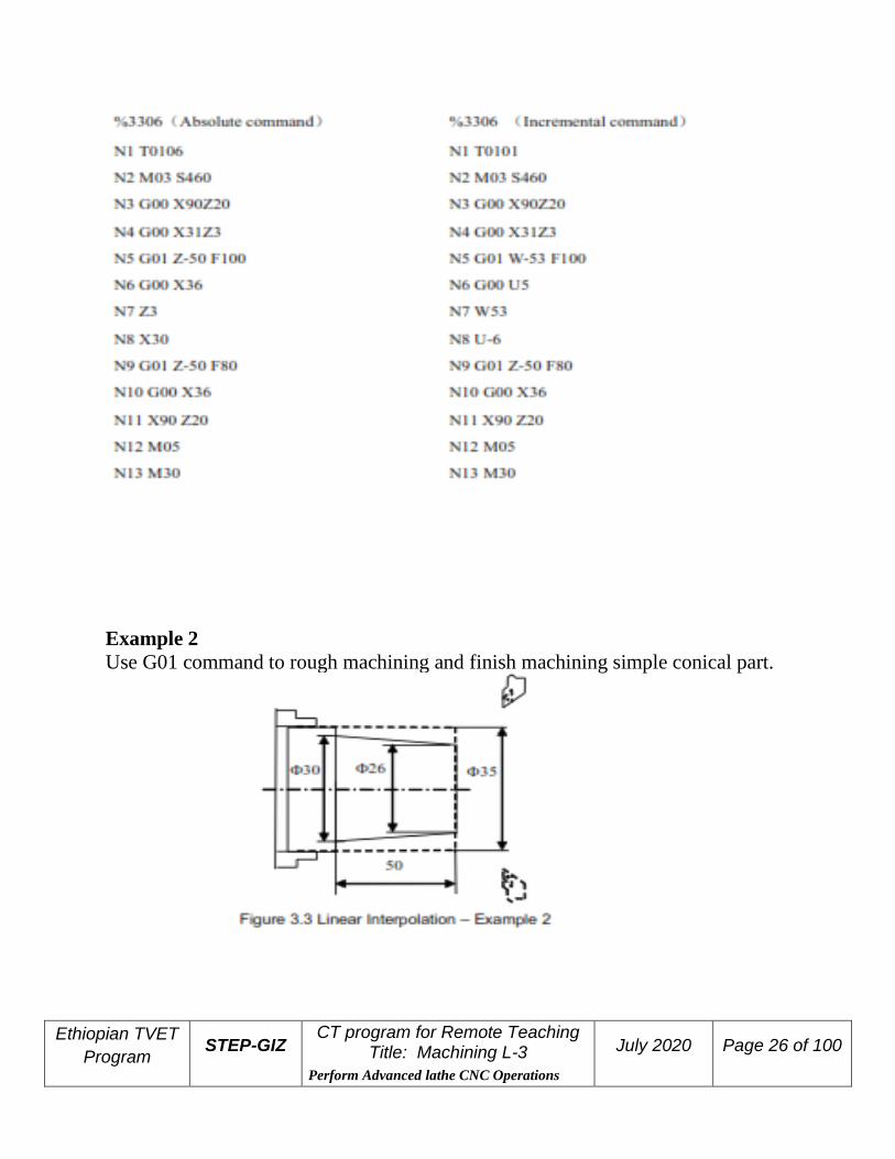
Example 2 Use G01 command to rough machining and finish machining simple conical part.

Ethiopian TVET
Program STEP-GIZ
CT program for Remote Teaching Title: Machining L-3
Perform Advanced lathe CNC Operations
July 2020 Page 27 of 100
Example 3 Use G01 command to rough machining and finish machining the part.

Ethiopian TVET
Program STEP-GIZ
CT program for Remote Teaching Title: Machining L-3
Perform Advanced lathe CNC Operations
July 2020 Page 28 of 100
Circulation Interpolation (G02, G03)
Explanation of the parameters
G02 a circular path in clockwise direction (CW)
G03 a circular path in counterclockwise direction (CCW)
Ethiopian TVET
Program STEP-GIZ
CT program for Remote Teaching Title: Machining L-3
Perform Advanced lathe CNC Operations
July 2020 Page 29 of 100
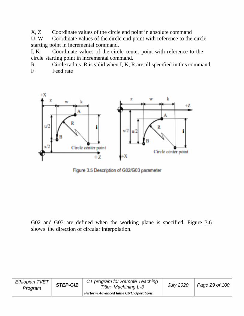
X, Z Coordinate values of the circle end point in absolute command
U, W Coordinate values of the circle end point with reference to the circle
starting point in incremental command.
I, K Coordinate values of the circle center point with reference to the
circle starting point in incremental command.
R Circle radius. R is valid when I, K, R are all specified in this command.
F Feed rate
G02 and G03 are defined when the working plane is specified. Figure 3.6
shows the direction of circular interpolation.

Ethiopian TVET
Program STEP-GIZ
CT program for Remote Teaching Title: Machining L-3
Perform Advanced lathe CNC Operations
July 2020 Page 30 of 100
Function
The tool is moved along a full circle or arcs.
Example 1 Use the circular interpolation command to program.
Example 2

Ethiopian TVET
Program STEP-GIZ
CT program for Remote Teaching Title: Machining L-3
Perform Advanced lathe CNC Operations
July 2020 Page 31 of 100
Use the circular interpolation command to program

Ethiopian TVET
Program STEP-GIZ
CT program for Remote Teaching Title: Machining L-3
Perform Advanced lathe CNC Operations
July 2020 Page 32 of 100
Example 3 Use the circular interpolation command to program.

Ethiopian TVET
Program STEP-GIZ
CT program for Remote Teaching Title: Machining L-3
Perform Advanced lathe CNC Operations
July 2020 Page 33 of 100
Example 4 Use the circular interpolation command to program
Ethiopian TVET
Program STEP-GIZ
CT program for Remote Teaching Title: Machining L-3
Perform Advanced lathe CNC Operations
July 2020 Page 34 of 100
Chamfering and Rounding (G01, G02, G03)
Note: These commands can not be used in thread cutting.
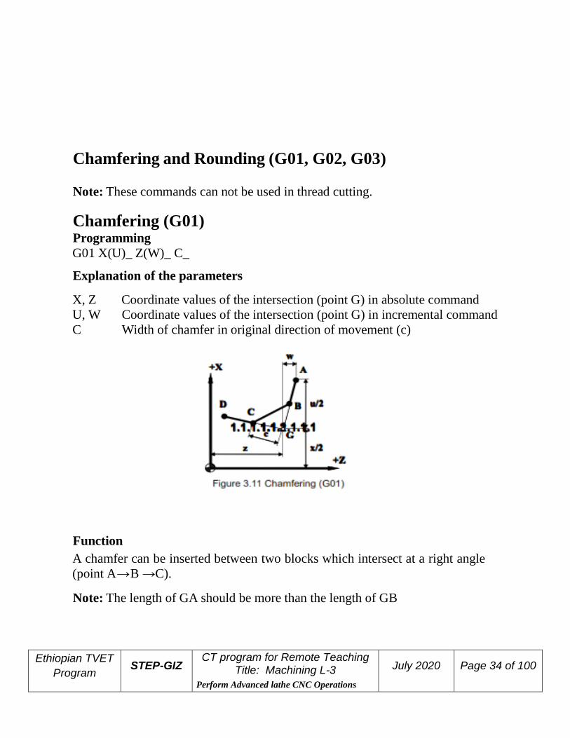
Chamfering (G01) Programming
G01 X(U)_ Z(W)_ C_
Explanation of the parameters
X, Z Coordinate values of the intersection (point G) in absolute command
U, W Coordinate values of the intersection (point G) in incremental command
C Width of chamfer in original direction of movement (c)
Function
A chamfer can be inserted between two blocks which intersect at a right angle
(point A→B →C).
Note: The length of GA should be more than the length of GB

Ethiopian TVET
Program STEP-GIZ
CT program for Remote Teaching Title: Machining L-3
Perform Advanced lathe CNC Operations
July 2020 Page 35 of 100
Rounding (G01) Programming
G01 X(U)_ Z(W)_ R_
Explanation of the parameters
X, Z Coordinate values of the intersection (point G) in absolute command
U, W Coordinate values of the intersection (pint G) in incremental command R Radius of the rounding (r)
Function
A corner can be inserted between two blocks which intersect at a right angle
(point A→B→ C).
Note: The length of GA should be more than the length of GB
Ethiopian TVET
Program STEP-GIZ
CT program for Remote Teaching Title: Machining L-3
Perform Advanced lathe CNC Operations
July 2020 Page 36 of 100
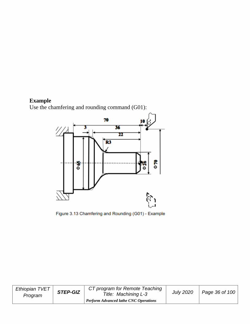
Example Use the chamfering and rounding command (G01):
Ethiopian TVET
Program STEP-GIZ
CT program for Remote Teaching Title: Machining L-3
Perform Advanced lathe CNC Operations
July 2020 Page 37 of 100
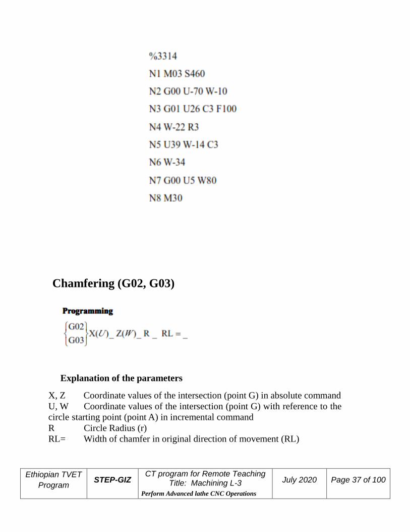
Chamfering (G02, G03)
Explanation of the parameters
X, Z Coordinate values of the intersection (point G) in absolute command
U, W Coordinate values of the intersection (point G) with reference to the
circle starting point (point A) in incremental command
R Circle Radius (r) RL= Width of chamfer in original direction of movement (RL)

Ethiopian TVET
Program STEP-GIZ
CT program for Remote Teaching Title: Machining L-3
Perform Advanced lathe CNC Operations
July 2020 Page 38 of 100
Function
A chamfer can be inserted between two blocks which intersect at a right angle
(point A→B →C).
Note: RL must be capitalized letters.
Rounding (G02, G03)
Explanation of the parameters
X, Z Coordinate values of the intersection (point G) in absolute command
U, W Coordinate values of the intersection (point G) with reference to the
circle starting point (point A) in incremental command
R Circle radius (r)
RC Radius of rounding (rc)

Ethiopian TVET
Program STEP-GIZ
CT program for Remote Teaching Title: Machining L-3
Perform Advanced lathe CNC Operations
July 2020 Page 39 of 100
Function
A corner can be inserted between two blocks which intersect at a right angle
(point A→B→ C).
Note: RC must be capitalized letters.
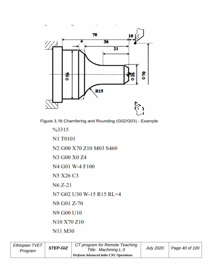
Example Use the chamfering and rounding command (G02/G03):
Ethiopian TVET
Program STEP-GIZ
CT program for Remote Teaching Title: Machining L-3
Perform Advanced lathe CNC Operations
July 2020 Page 40 of 100

Ethiopian TVET
Program STEP-GIZ
CT program for Remote Teaching Title: Machining L-3
Perform Advanced lathe CNC Operations
July 2020 Page 41 of 100
Thread Cutting with Constant Lead (G32) Programming
G32 X(U) Z(W) R E__P F
Explanation of the parameters
X, Z Coordinate values of end point in absolute command
U, W Coordinate values of end point with reference to the starting point in
incremental command
R, E Coordinate v a l u e o f r e t r ac t i on a mo un t w i t h r e f e r en c e t o the
end p o in t i n incremental command. In general, R is set as two times value of
thread lead, and E is set as the thread height.
P Start point offset. It is used for multiple threads.
F Thread lead per revolution

Ethiopian TVET
Program STEP-GIZ
CT program for Remote Teaching Title: Machining L-3
Perform Advanced lathe CNC Operations
July 2020 Page 42 of 100
Function
Cylindrical thread, taper thread and face thread can be machined with G32.
Note:
1) The spindle speed should remain constant during rough cutting and finish
cutting.
2) The feed hold function is ineffective during the thread cutting. Even
though the “feed hold” button is pressed, it is effective until the thread cutting
is done.
3) It is not recommended to use the constant surface speed control during
the thread cutting.
4) Allowant amount must be specified to avoid the error.
Example Given that F=1.5mm, δ =1.5mm, δ′ =1mm, cutting for four times and each cutting depth is
separately: 0.8mm, 0.6 mm, 0.4mm, 0.16mm. It is diameter programming.

Ethiopian TVET
Program STEP-GIZ
CT program for Remote Teaching Title: Machining L-3
Perform Advanced lathe CNC Operations
July 2020 Page 43 of 100
Tapping (G34)
Programming
G34 K_ F_ P_
Explanation of the parameters
K The distance from the starting point to the bottom of the hole
F Thread lead
P Dwell time at the bottom of a hole
Function

Ethiopian TVET
Program STEP-GIZ
CT program for Remote Teaching Title: Machining L-3
Perform Advanced lathe CNC Operations
July 2020 Page 44 of 100
With this command, the operator can rigid tap a thread.
In general, there is overshoot of the tap at the bottom of the thread during the spindle-
braking portion of the tapping cycle. It can be set by PMC parameters (Table 3-1) to eliminate
the overshoot errors.
Feed Function
There are two kinds of feed functions:
1. Rapid Traverse
The tool is moved at the rapid traverse speed set in CNC.
2. Cutting Feed
The tool is moved at the programmed cutting feed rate.
Rapid Traverse (G00) Positioning command (G00) is to move the tool at the rapid traverse speed
(the highest possible speed).
This rapid traverse speed can be controlled by the machine control panel. For
more detailed information, please refer to turning operation manual.
Cutting Feed (G94, G95)
Programming
G94 [F_ ]
G95 [F_ ]
Explanation of the parameters
G94 feed rate per minute. On linear axis, the unit of feed rate is mm/min, or in/min. On
rational axis, the unit of feed rate is degree/min.
G95 feed rate per revolution
The unit of feed rate is mm/rev, or in/rev.
Note:
1) G94 is the default setting
2) G95 is only used when there is spindle encoder.

Ethiopian TVET
Program STEP-GIZ
CT program for Remote Teaching Title: Machining L-3
Perform Advanced lathe CNC Operations
July 2020 Page 45 of 100
Function
The feed rate can be set by G94 or G95.
Dwell (G04)
Programming
G04 P_
Explanation of the parameters
P dwell time (specified in seconds)
Function
It can be used to interrupt machining to get the smooth surface. It can be used to
control the groove cutting, drilling, and turning path.
Coordinate System
This chapter would introduce:
1) Reference Position Return (G28)
2) Auto Return from Reference Position (G29)
3) Setting a Workpiece Coordinate System (G92)
4) Selecting a Machine Coordinate System (G53)
5) Selecting a Workpiece Coordinate System (G54~G59)
6) Origin of a Workpiece Coordinate System (G51, G50)
7) Absolute and Incremental Programming (G90, G91)
8) Diameter and Radius Programming (G36, G37)
9) Inch/Metric Conversion (G20, G21)

Ethiopian TVET
Program STEP-GIZ
CT program for Remote Teaching Title: Machining L-3
Perform Advanced lathe CNC Operations
July 2020 Page 46 of 100
Reference Position Return (G28)
Programming
G28 X(U)_ Z(W)_
Explanation of the parameters
X, Z Coordinate values of the intermediate point in absolute command
U,W Coordinate values of the intermediate point with reference to the
starting point in incremental command
Function
The tool is moved to the intermediate point rapidly, and then returned to the
reference point.

Ethiopian TVET
Program STEP-GIZ
CT program for Remote Teaching Title: Machining L-3
Perform Advanced lathe CNC Operations
July 2020 Page 47 of 100
Note:
1) In general, G28 is used to change tools or cancel the mechanical error.
Tool radius compensation and tool length compensation should be cancelled when
G28 is executed.
2) G28 can not only make the tool move to the reference point, but also can save the
intermediate position to be used in G29.
3) When the power is on and manual reference position return is not available,
G28 is same as the manual reference position return. The direction of this
reference position return (G28) is set by the axis parameter – reference
approach direction.
4) G28 is one-shot G code.
Auto Return from Reference Position (G29)
Programming
G29 X(U)_ Z(W)_
Explanation of the parameters
X, Z Coordinate value of the end point in absolute command
U, W Coordinate value of the end point in incremental command
Function
The tool is moved rapidly from the intermediate point defined in G28 to the end
point. Thus, G29 is generally used after G28 is defined.
Note:
G29 is one-shot G code.

Ethiopian TVET
Program STEP-GIZ
CT program for Remote Teaching Title: Machining L-3
Perform Advanced lathe CNC Operations
July 2020 Page 48 of 100
Example
Use G28, G29 command to program the track shown in. It moves from the
starting point A to the intermediate point B, and then returns to the reference
point R. At last, it moves from the reference point R to the end point C through
the intermediate point B.
%3317
N1 T0101
N2 G00 X50 Z100
N3 G28 X80 Z200
N4 G29 X40 Z250
N5 G00 X50Z100
N6 M30
Setting a Workpiece Coordinate System (G92) Programming
G92 X_ Z_
Explanation of the parameters
X, Z Coordinate values of the tool position in the workpiece coordinate
system.
Functions G92 can set a workpiece coordinate system based on the current tool position (X_ Z_).
Example

Ethiopian TVET
Program STEP-GIZ
CT program for Remote Teaching Title: Machining L-3
Perform Advanced lathe CNC Operations
July 2020 Page 49 of 100
Use G92 to set a workpiece coordinate system.
If the origin is set on the left end face,
G92 X180 Z254
If the origin is set on the right end face
G92 X180 Z44
Selecting a Machine Coordinate System (G53) Programming
G53 X_Z_
Explanation of the parameters
X, Z Absolute coordinate values of a point in the machine coordinate system.
Function
A machine coordinate system is selected, and the tool moves to the position at
the rapid traverse speed.
Note:
1) Absolute values must be specified in G53. The incremental values would
be ignored by G53.
2) G53 is one-shot G code.
Selecting a Workpiece Coordinate System (G54~G59)

Ethiopian TVET
Program STEP-GIZ
CT program for Remote Teaching Title: Machining L-3
Perform Advanced lathe CNC Operations
July 2020 Page 50 of 100
Explanation of the parameters
X, Z Coordinate values of the point in absolute command
Function
There are six workpiece coordinate system to be selected. If one coordinate
system is selected, the tool is moved to a specified point.
Note:
1) The workpiece coordinate system must be set before these commands
(G54~G59) are used. The workpiece coordinate system can be set by using
the MDI panel. For detailed information, please refer to the turning
operation manual.
2) Reference position must be returned before these commands (G54~G59)
are executed.
3) G54 is the default setting.
Example
Select one of workpiece coordinate system, and the tool path is Current
point→A→B.

Ethiopian TVET
Program STEP-GIZ
CT program for Remote Teaching Title: Machining L-3
Perform Advanced lathe CNC Operations
July 2020 Page 51 of 100
Origin of a Workpiece Coordinate System (G51, G50)
Programming

Ethiopian TVET
Program STEP-GIZ
CT program for Remote Teaching Title: Machining L-3
Perform Advanced lathe CNC Operations
July 2020 Page 52 of 100
G51U_ W_ G50
Explanation of the parameters
G51 can move the origin of workpiece coordinate system.
U, W Coordinate values of the position in incremental command
G50 can cancel the movement.
Function
The origin of workpiece coordinate system can be moved.
Note:
1) G51 is only effective when T command or G54~G59 is defined in the
program.
2) G50 is only effective when T command or G54~G59 is defined in the
program.
Absolute and Incremental Programming (G90, G91)

Ethiopian TVET
Program STEP-GIZ
CT program for Remote Teaching Title: Machining L-3
Perform Advanced lathe CNC Operations
July 2020 Page 53 of 100
Programming G90
X_ Z_ G91 U_W_
Explanation of the parameters
G90 Absolute programming
X, Z Coordinate values on X axis and Z axis in the coordinate system
G91 Incremental programming
U, W Coordinate values with reference to the previous position in the
coordinate system
Function
The tool is moved to the specified position.
Example Move the tool from point 1 to point 2 through point 3, and then return to the
current point.

Ethiopian TVET
Program STEP-GIZ
CT program for Remote Teaching Title: Machining L-3
Perform Advanced lathe CNC Operations
July 2020 Page 54 of 100
Diameter and Radius Programming (G36, G37)
Programming
G36
G37
Explanation of the parameters
G36 Diameter programming
G37 Radius programming
Function
The coordinate value on X axis is specified in two ways: diameter or radius. It
allows to program the dimension straight from the drawing without conversion.
Note:
1) In all the examples of this book, we always use diameter programming
if the radius programming is not specified.
2) If the machine parameter is set to diameter programming, then
diameter programming is the default setting. However, G36 and G37 can
be used to exchange. The system shows the diameter value.
3) If the system parameter is set to radius programming, then radius
programming is the default setting. However, G36 and G37 can be used to
exchange. The system shows the radius value.
Example Use Diameter programming and Radius programming for the same path

Ethiopian TVET
Program STEP-GIZ
CT program for Remote Teaching Title: Machining L-3
Perform Advanced lathe CNC Operations
July 2020 Page 55 of 100
Inch/Metric Conversion (G20, G21)
Programming
G20
G21
Explanation of the parameters
G20: Inch input
G21: Metric input
The units of linear axis and circular axis are shown in the following table

Ethiopian TVET
Program STEP-GIZ
CT program for Remote Teaching Title: Machining L-3
Perform Advanced lathe CNC Operations
July 2020 Page 56 of 100
Function
Depending on the part drawing, the workpiece geometries can be programmed
in metric measures or inches.
Spindle Speed Function
Spindle function controls the spindle speed (S), the unit of spindle speed is
r/min. Spindle speed is the cutting speed when it is at the constant speed, the unit
of speed is m/min.
S is modal G code command; it is only available when the spindle is
adjustable. Spindle speed programmed by S code can be adjusted by overrides on
the machine control panel.
This chapter would introduce
1) Limit of spindle speed (G46)
2) Constant surface cutting control (G96, G97).
1 Limit of Spindle Speed (G46)
Programming
G46 X_ P_
Explanation of the parameters
X The minimum speed of the spindle when using constant surface speed(r/min
P The maximum speed of the spindle when using constant surface speed(r/min

Ethiopian TVET
Program STEP-GIZ
CT program for Remote Teaching Title: Machining L-3
Perform Advanced lathe CNC Operations
July 2020 Page 57 of 100
Function
G46 command can set the minimum of spindle speed, and the maximum of
spindle speed.
Note:
It can only used with G96 (constant surface speed control command).
2 Constant Surface Speed Control (G96, G97)
Programming
G96 S G97 S
Explanation of the parameters
G96 activate the constant surface speed
S surface speed (m/min)
G97 deactivate the constant surface speed
S spindle speed (r/min)
Function
G96 and G97 commands are to control the constant surface speed.
Note:
1) The spindle speed must be controlled automatically when the constant
surface cutting command is executed.
2) The maximum of spindle speed can be set by the axis parameter.
Example Use the constant surface control command

Ethiopian TVET
Program STEP-GIZ
CT program for Remote Teaching Title: Machining L-3
Perform Advanced lathe CNC Operations
July 2020 Page 58 of 100
Tool Function
This chapter would introduce:
1) Too selection and Tool offset (T code)
2) Tool radius compensation (G40, G41, G42)
1 Tool Selection and Tool Offset (T code)
Programming

Ethiopian TVET
Program STEP-GIZ
CT program for Remote Teaching Title: Machining L-3
Perform Advanced lathe CNC Operations
July 2020 Page 59 of 100
T XX XX
Explanation of the parameters
XX Tool number (two digits). The number of tool depends on
manufacture’s configuration.
XX Tool offset number (two digits). It corresponds to the specific
compensation value.
Functions
To select the desired tool, T command makes the turret turn, selects a cutter,
and calls the compensation value.
Note:
1) T command is only effective when it is used with tool move command,
such as G00
2) When T command and tool move command are in the same program
block, T command is executed at first.
3) The same tool can have different compensation values. For
example, T0101, T0102, T0103 are possible.
4) Different tool can have same compensation values. For example,
T0101, T0201, and T0301 are possible.

Ethiopian TVET
Program STEP-GIZ
CT program for Remote Teaching Title: Machining L-3
Perform Advanced lathe CNC Operations
July 2020 Page 60 of 100
2 Tool Radius Compensation (G40, G41, G42)
Explanation of the parameters
G40 Deactivate tool radius compensation
G41 Activate tool radius compensation, tool operates in machining
operation to the left of the contour.
G42 Activate tool radius compensation, tool operates in machining
operation to the right of the contour.

Ethiopian TVET
Program STEP-GIZ
CT program for Remote Teaching Title: Machining L-3
Perform Advanced lathe CNC Operations
July 2020 Page 61 of 100
X, Z Coordinate values of the end point. It is the point where the
tool radius compensation is activated or deactivated.
Function
These commands can control the tool radius compensation to get the equidistant
tool paths for different tools.
Note:
1) G40, G41, and G42 must be used with G00 or G01.
2) The tool radius compensation value is assigned in T code.
Example Use the tool radius compensation, and program for the part shown in Figure 7.2

Ethiopian TVET
Program STEP-GIZ
CT program for Remote Teaching Title: Machining L-3
Perform Advanced lathe CNC Operations
July 2020 Page 62 of 100
Miscellaneous Function
As it is mentioned in Chapter 1.8, there are two ways of execution when a move
command and M code are specified in the same block.
1) Pre-M function
M command is executed before the completion of move command.
2) Post-M function
M command is executed after the completion of move command
There are two types of M code: one-shot M code, and modal M code.

Ethiopian TVET
Program STEP-GIZ
CT program for Remote Teaching Title: Machining L-3
Perform Advanced lathe CNC Operations
July 2020 Page 63 of 100
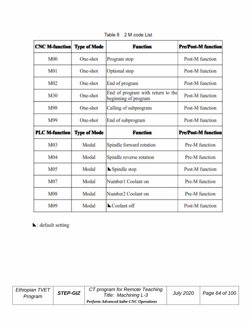
M code List The following is a list of M command.
Ethiopian TVET
Program STEP-GIZ
CT program for Remote Teaching Title: Machining L-3
Perform Advanced lathe CNC Operations
July 2020 Page 64 of 100

Ethiopian TVET
Program STEP-GIZ
CT program for Remote Teaching Title: Machining L-3
Perform Advanced lathe CNC Operations
July 2020 Page 65 of 100
CNC M-Function
Program Stop (M00) M00 is one-shot M function, and it is post-M function
The program can be stopped, so that the operator could measure the tool and the
part, adjust part and change speed manually, and so on.
When the program is stopped, the spindle is stopped and the coolant is off. All of
the current modal information remains unchanged. Resuming program could be
executed by pushing “Cycle Run” button on the machine control panel.
Optional Stop (M01) M01 is one-shot M function, and it is post-M function
Similarly to M00, M01 can also stop the program. All of the modal information is
maintained. The difference between M00 and M01 is that the operator must
press M01 button ( ) on the machine control panel. Otherwise, the program
would not be stopped even if there is M01 code in the program.
End of Program (M02) M02 is one-shot M function, and it is post-M function
When M02 is executed, spindle, feed and coolant are all stopped. It is usually at
the end of the last program block. To restart the program, press “Cycle Run”
button on the operational panel.
End of Program with return to the beginning of program
(M30) M30 is one-shot M function, and it is post-M function
Similarly to M02, M30 can also stop the program. The difference is that M30
returns control to the beginning of program. To restart the program, press “Cycle
Run” button on the operational panel.

Ethiopian TVET
Program STEP-GIZ
CT program for Remote Teaching Title: Machining L-3
Perform Advanced lathe CNC Operations
July 2020 Page 66 of 100
Subprogram Control (M98, M99)
➢ End of Subprogram (M99)
M99 indicates the end of subprogram and returns control to the main program. It
is one-shot
M function, and it is post-M function.
➢ Calling a Subprogram(M98)
M98 P_ L_
P program number of the subprogram
L repeated times of subprogram
M98 is used to call a subprogram. It is one-shot M function. Moreover, it is post-
M function.
Example

Ethiopian TVET
Program STEP-GIZ
CT program for Remote Teaching Title: Machining L-3
Perform Advanced lathe CNC Operations
July 2020 Page 67 of 100
PLC M Function
Spindle Control (M03, M04, M05) M03 starts spindle to rotate CW at the set speed set in the program. M04 starts spindle to rotate CCW at the set speed in the program. M05 stops spindle. M03, M04 are modal M code, and they are pre-M function. M05 is modal M code,
and it is post-M function. M05 is the default setting.
Coolant Control (M07, M08, M09) M07, M08 can turn on the coolant.
M09 can turn off the coolant.
M07 and M08 are modal M code, and they are pre-M function. M09 is one-
shot M code, and it is post-M function. Moreover, M09 is the default setting.
Functions to Simplify Programming
This chapter would introduce:
1) Canned Cycle
Internal diameter/ Outer diameter cutting cycle
(G80) End face turning cycle (G81)
Thread cutting cycle (G82)
End face peck drilling cycle (G74)
Outer diameter grooving cycle (G75)
2) Multiple Repetitive Cycle
Stock Removal in Turning (G71)

Ethiopian TVET
Program STEP-GIZ
CT program for Remote Teaching Title: Machining L-3
Perform Advanced lathe CNC Operations
July 2020 Page 68 of 100
Stock Removal in Facing (G72)
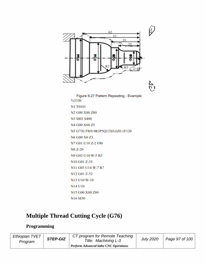
Pattern Repeating (G73)
Multiple Thread Cutting Cycle (G76)
1 Canned Cycles
To simplify programming, the canned cycle command can execute the
specific operation using one G code, instead of several separated G commands in
the program.
Internal Diameter/Outer Diameter Cutting Cycle (G80)
➢ Straight Cutting Cycle
Programming
G80 X(U)_ Z(W)_ F_
Explanation of the parameters
X, Z Coordinate values of end point (point C) in absolute command
U, W Coordinate values of end point (point C) with reference to the initial
point (point A) in incremental command
F Feed rate

Ethiopian TVET
Program STEP-GIZ
CT program for Remote Teaching Title: Machining L-3
Perform Advanced lathe CNC Operations
July 2020 Page 69 of 100
Function
This command can implement the straight cutting. The machining
path is A→B→C→D→A.
➢ Taper Cutting Cycle
Programming
G80 X(U)_ Z(W)_ I_ F_
Explanation of the parameters
X, Z Coordinate values of end point (point C) in absolute command
U, W Coordinate values of end point (point C) with reference to the initial
point (point A) in incremental command
I The radius difference between starting point B and end point C. It is
negative, if the radius of point B is less than the radius of point C. Otherwise, it
is positive.
F Feed rate
Function

Ethiopian TVET
Program STEP-GIZ
CT program for Remote Teaching Title: Machining L-3
Perform Advanced lathe CNC Operations
July 2020 Page 70 of 100
This command can implement the taper cutting. The machining path is
A→B→C→D→A.
Example Use G80 command to machine the cylindrical part in two steps – rough machining and
finish machining.
Example
Use G80 command to machine the tapered part in two steps – rough machining and
finish machining.

Ethiopian TVET
Program STEP-GIZ
CT program for Remote Teaching Title: Machining L-3
Perform Advanced lathe CNC Operations
July 2020 Page 71 of 100
Example Use G80 command to machine the tapered part in two steps – rough machining and
finish machining.

Ethiopian TVET
Program STEP-GIZ
CT program for Remote Teaching Title: Machining L-3
Perform Advanced lathe CNC Operations
July 2020 Page 72 of 100
End Face Turning Cycle (G81)
➢ Face Cutting Cycle
Programming
G81 X(U)_ Z(W)_ F_
Explanation of the parameters
X, Z Coordinate values of end point (point C) in absolute command
U, W Coordinate values of end point (point C) with reference to the initial
point (point A) in incremental command F Feed rate

Ethiopian TVET
Program STEP-GIZ
CT program for Remote Teaching Title: Machining L-3
Perform Advanced lathe CNC Operations
July 2020 Page 73 of 100
Function
This command can implement the end face cutting. The machining
path is A→B→C→D→A.
➢ Taper Face Cutting Cycle
Programming
G81 X(U)_ Z(W)_ K_ F_
Explanation of the parameters
X, Z Coordinate values of end point (point C) in absolute
command
U, W Coordinate values of end point (point C) with reference to the initial point
(point A) in incremental command
K The distance on Z axis of the starting point (point B) with reference to the
end point (point C). It is negative, if the value of point C on Z axis is more than

Ethiopian TVET
Program STEP-GIZ
CT program for Remote Teaching Title: Machining L-3
Perform Advanced lathe CNC Operations
July 2020 Page 74 of 100
point B’s. It is positive, if the value of point C on Z axis is less than point B’s.
F Feed rate
Function
This command can implement the taper face cutting. The machining
path is A→B→C→D→A.
Example Use G81 to program. The dashed line stands for the roughcast.

Ethiopian TVET
Program STEP-GIZ
CT program for Remote Teaching Title: Machining L-3
Perform Advanced lathe CNC Operations
July 2020 Page 75 of 100
Thread Cutting Cycle (G82)
➢ Cylindrical Thread Cutting Cycle

Ethiopian TVET
Program STEP-GIZ
CT program for Remote Teaching Title: Machining L-3
Perform Advanced lathe CNC Operations
July 2020 Page 76 of 100
Programming
G82 X(U)_ Z(W)_ R_ E_ C_ P_ F(J)_
Explanation of the parameters
X, Z Coordinate values of end point (point C) in absolute command
U, W Coordinate values of end point (point C) with reference to the initial point
(point A) in incremental command
R, E Coordinate value of retraction amount with reference to the end point
(point C) in incremental command.
C The number of thread head. It is single thread when C is 0 or 1
P Start point offset. It is used for multiple threads.
F Thread lead per revolution
J Thread lead in inch measurement
Function
This command can implement the cylindrical thread cutting. The machining path
is A→B→C→D→A. Moreover, this command is same as G32 (Thread cutting
with constant lead).
➢ Taper Thread Cutting Cycle

Ethiopian TVET
Program STEP-GIZ
CT program for Remote Teaching Title: Machining L-3
Perform Advanced lathe CNC Operations
July 2020 Page 77 of 100
Programming
G82 X(U)_ Z(W)_ I_ R_ E_ C_ P_ F(J)_
Explanation of the parameters
X, Z Coordinate values of end point (point C) in absolute command
U, W Coordinate values of end point (point C) with reference to the initial
point (point A) in incremental command
I The radius difference between starting point B and end point C. It is
negative, if the radius of point B is less than the radius of point C. Otherwise, it
is positive.
R, E Coordinate value of retraction amount with reference to the end point
(point C) in incremental command.
C The number of thread head. It is single thread when C is 0 or 1. P Start point offset. It is used for multiple threads. F Thread lead per revolution J Thread lead in inch measurement
Function
This command can implement the taper thread cutting. The machining
path is A→B→C→D→A.

Ethiopian TVET
Program STEP-GIZ
CT program for Remote Teaching Title: Machining L-3
Perform Advanced lathe CNC Operations
July 2020 Page 78 of 100
Example
Use G82 command to program. The screw’s pitch is 1.5, and the number of thread
head is 2.

Ethiopian TVET
Program STEP-GIZ
CT program for Remote Teaching Title: Machining L-3
Perform Advanced lathe CNC Operations
July 2020 Page 79 of 100
End Face Peck Drilling Cycle (G74)
Programming
G74 Z(W)_ R(e) Q(△K) F_
Explanation of the parameters
Z Coordinate value on Z axis of the end point in absolute command
W Coordinate value on Z axis of the end point with reference to the
starting point in incremental command
R Retraction amount(e) for each feed. It must be absolute value.
Q Depth of drilling(△K) for each feed. It must be absolute
value.
F Feed rate
Function
This command can drill a hole on end face.

Ethiopian TVET
Program STEP-GIZ
CT program for Remote Teaching Title: Machining L-3
Perform Advanced lathe CNC Operations
July 2020 Page 80 of 100
Example
Use G74 to drill a hole on a workpiece.
Ethiopian TVET
Program STEP-GIZ
CT program for Remote Teaching Title: Machining L-3
Perform Advanced lathe CNC Operations
July 2020 Page 81 of 100
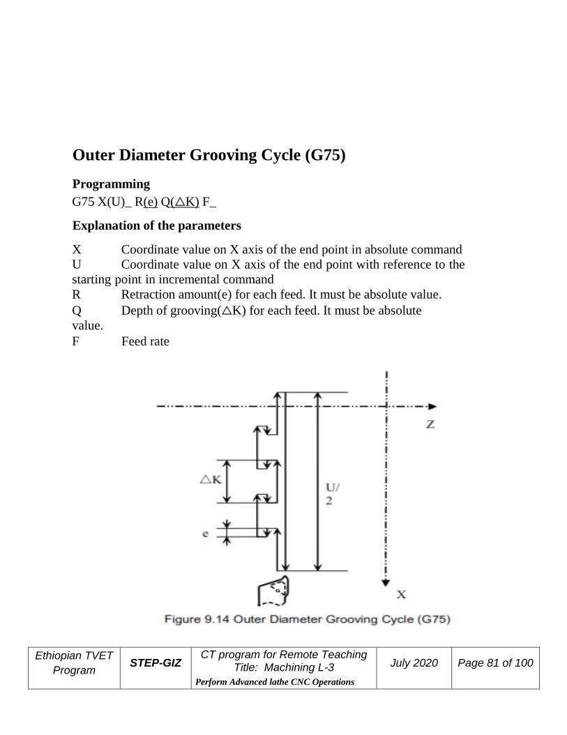
Outer Diameter Grooving Cycle (G75) Programming
G75 X(U)_ R(e) Q(△K) F_
Explanation of the parameters
X Coordinate value on X axis of the end point in absolute command
U Coordinate value on X axis of the end point with reference to the
starting point in incremental command
R Retraction amount(e) for each feed. It must be absolute value.
Q Depth of grooving(△K) for each feed. It must be absolute
value.
F Feed rate

Ethiopian TVET
Program STEP-GIZ
CT program for Remote Teaching Title: Machining L-3
Perform Advanced lathe CNC Operations
July 2020 Page 82 of 100
Function
This command can be used for grooving.
Example
Use G75 to groove a hole on a workpiece.

Ethiopian TVET
Program STEP-GIZ
CT program for Remote Teaching Title: Machining L-3
Perform Advanced lathe CNC Operations
July 2020 Page 83 of 100
Multiple Repetitive Cycle Multiple repetitive cycle command can only use one command to finish
the rough machining and the finish machining.
Stock Removal in Turning (G71)
➢ Stock Removal in Turning without Groove
Programming
G71 U(△d) R(r) P(ns) Q(nf) X(△x) Z(△z) F(f) S(s) T(t)
Explanation of the parameters
U(△d) the cutting depth (radius designation). The cutting direction depends
on the direction of AA’.
R(r) Retraction amount

Ethiopian TVET
Program STEP-GIZ
CT program for Remote Teaching Title: Machining L-3
Perform Advanced lathe CNC Operations
July 2020 Page 84 of 100
P(ns) Sequence number of the first block for the finishing program.
Q(nf) Sequence number of the last block for the finishing program.
X(△x) Distance and direction of finishing allowance on X axis
Z(△z) Distance and direction of finishing allowance on Z axis
F(f), S(s), T(t) F, S, T function are only effective for the rough machining,
i.e, it is not effective in the finishing program – between P(ns) and Q(nf).
Function
This command can do a stock removal in facing without groove. The
machining path is A→A'→B
Note
1) G00 or G01 must be used in the finishing program – between P(ns)
and Q(nf).
Otherwise, there is an alarm message.
2) G71 can not be used in MDI mode.
3) G98 and G99 can not used in the finishing program – between P(ns) and
Q(nf).
4) The direction of △x and △z is shown in the following figure.

Ethiopian TVET
Program STEP-GIZ
CT program for Remote Teaching Title: Machining L-3
Perform Advanced lathe CNC Operations
July 2020 Page 85 of 100
Example
Example 1
The initial point A is (46, 3). The depth of cut is 1.5mm (radius designation). The
retraction amount is 1mm. The finishing allowance in the X direction is 0.6mm,
and the finishing allowance in the Z direction is 0.1mm. The dashed line stands for
the original part.
Ethiopian TVET
Program STEP-GIZ
CT program for Remote Teaching Title: Machining L-3
Perform Advanced lathe CNC Operations
July 2020 Page 86 of 100
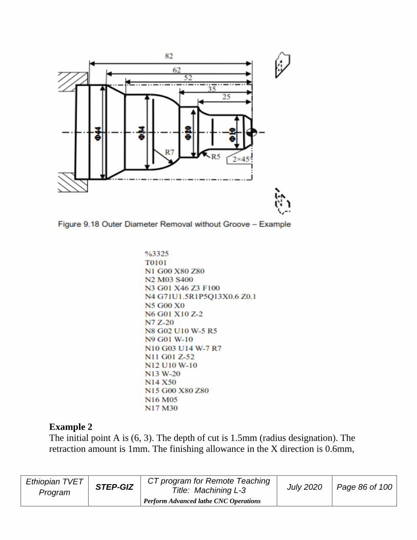
Example 2 The initial point A is (6, 3). The depth of cut is 1.5mm (radius designation). The
retraction amount is 1mm. The finishing allowance in the X direction is 0.6mm,

Ethiopian TVET
Program STEP-GIZ
CT program for Remote Teaching Title: Machining L-3
Perform Advanced lathe CNC Operations
July 2020 Page 87 of 100
and the finishing allowance in the Z direction is 0.1mm. The dashed line stands for
the original part.
➢ Stock Removal in Turning with Groove

Ethiopian TVET
Program STEP-GIZ
CT program for Remote Teaching Title: Machining L-3
Perform Advanced lathe CNC Operations
July 2020 Page 88 of 100
Programming
G71 U(△d) R(r) P(ns) Q(nf) E(e) F(f) S(s) T(t)
Explanation of the parameters
U(△d) the cutting depth (radius designation). The cutting direction depends
on the direction of AA’.
R(r) Retraction amount
P(ns) Sequence number of the first block for the finishing program.
Q(nf) Sequence number of the last block for the finishing program.
E(e) Distance and direction of finishing allowance on X axis. It is
positive when it is outer diameter cutting. It is negative when it is internal
diameter cutting.
F(f), S(s), T(t) F, S, T function are only effective for the rough machining,
i.e, it is not effective in the finishing program – between P(ns) and Q(nf).
Function
This command can do a stock removal in facing with groove. The
machining path A→A'→B’→B.

Ethiopian TVET
Program STEP-GIZ
CT program for Remote Teaching Title: Machining L-3
Perform Advanced lathe CNC Operations
July 2020 Page 89 of 100
Example
Use G71 to program.

Ethiopian TVET
Program STEP-GIZ
CT program for Remote Teaching Title: Machining L-3
Perform Advanced lathe CNC Operations
July 2020 Page 90 of 100
Stock Removal in Facing (G72) Programming
G72 W(Δd) R(r) P(ns) Q(nf) X(Δx) Z(Δz) F(f) S(s) T(t)
Explanation of the parameters
W(△d) the cutting depth (radius designation). The cutting direction depends
on the direction of AA’.
R(r) Retraction amount
P(ns) Sequence number of the first block for the finishing program.
Q(nf) Sequence number of the last block for the finishing program.
X(△x) Distance and direction of finishing allowance on X axis
Z(△z) Distance and direction of finishing allowance on Z axis
F(f), S(s), T(t) F, S, T function are only effective for the rough machining,
i.e, it is not effective in the finishing program – between P(ns) and Q(nf).
Function
This command can do a stock removal in facing. The machining path is A→A'→B

Ethiopian TVET
Program STEP-GIZ
CT program for Remote Teaching Title: Machining L-3
Perform Advanced lathe CNC Operations
July 2020 Page 91 of 100
Note
1) G00 or G01 must be used in the finishing program – between P(ns) and
Q(nf).
Otherwise, there is an alarm message.
2) G72 can not be used in MDI mode.
3) G98 and G99 can not used in the finishing program – between P(ns) and Q(nf).
4) The direction of △x and △z is shown in the following figure.

Ethiopian TVET
Program STEP-GIZ
CT program for Remote Teaching Title: Machining L-3
Perform Advanced lathe CNC Operations
July 2020 Page 92 of 100
Example 1
Use G72 to program. The initial point A is (80, 1). The depth of cutting is 1.2mm.
The retraction amount is 1mm. The finishing allowance in the X direction is
0.2mm, and the finishing allowance in the Z direction is 0.5mm. The dashed line
stands for the original part.

Ethiopian TVET
Program STEP-GIZ
CT program for Remote Teaching Title: Machining L-3
Perform Advanced lathe CNC Operations
July 2020 Page 93 of 100
Example 2
Use G72 to program. The initial point A is (80, 1). The depth of cutting is 1.2mm.
The retraction amount is 1mm. The finishing allowance in the X direction is
0.2mm, and the finishing allowance in the Z direction is 0.5mm. The dashed line
stands for the original part.

Ethiopian TVET
Program STEP-GIZ
CT program for Remote Teaching Title: Machining L-3
Perform Advanced lathe CNC Operations
July 2020 Page 94 of 100
Pattern Repeating (G73) Programming
G73 U(ΔI) W(ΔK) R(r) P(ns) Q(nf) X(Δx) Z(Δz) F(f) S(s) T(t)
Explanation of the parameters
U(△I) distance and direction of total roughing allowance in the X direction
(radius designation).
W(△K) distance and direction of total roughing allowance in the X direction
(radius designation)
R(r) Repeated times of cutting
P(ns) Sequence number of the first block for the finishing program.
Q(nf) Sequence number of the last block for the finishing program.
X(△x) Distance and direction of finishing allowance on X axis
Z(△z) Distance and direction of finishing allowance on Z axis
F(f), S(s), T(t) F, S, T function are only effective for the rough machining,
i.e, it is not effective in the finishing program – between P(ns) and Q(nf).

Ethiopian TVET
Program STEP-GIZ
CT program for Remote Teaching Title: Machining L-3
Perform Advanced lathe CNC Operations
July 2020 Page 95 of 100
Function G73 command can cut a workpiece at a fixed pattern repeatedly. The machining path is A→A'→B.
Note
1) G00 or G01 must be used in the finishing program – between P(ns) and
Q(nf).
Otherwise, there is an alarm message.
2) G73 can not be used in MDI mode.
3) G98 and G99 can not used in the finishing program – between P(ns) and Q(nf).
4) The depth for each cutting on X axis = △I/r
The depth for each cutting on Z axis = △K/r
5) The direction of △I and △K, and the direction of △x and △z should be
noted.

Ethiopian TVET
Program STEP-GIZ
CT program for Remote Teaching Title: Machining L-3
Perform Advanced lathe CNC Operations
July 2020 Page 96 of 100
Example
Use G73 to program. The initial point A is (60, 5). The total roughing allowance
on X and Z axis are 3mm, 0.9mm, respectively. The times of rough cutting is 3.
The finishing allowance on X and Z axis are 0.6mm, 0.1mm respectively. The
dash-dot-line is the part’s blank.
Ethiopian TVET
Program STEP-GIZ
CT program for Remote Teaching Title: Machining L-3
Perform Advanced lathe CNC Operations
July 2020 Page 97 of 100
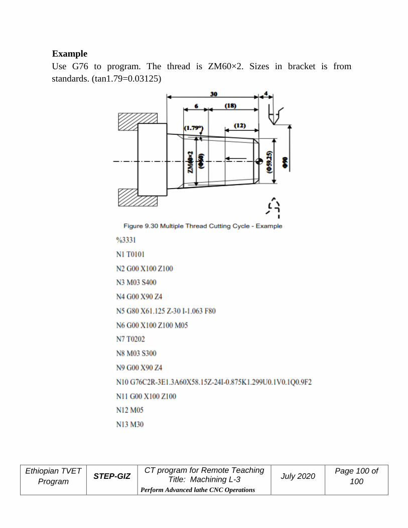
Multiple Thread Cutting Cycle (G76) Programming

Ethiopian TVET
Program STEP-GIZ
CT program for Remote Teaching Title: Machining L-3
Perform Advanced lathe CNC Operations
July 2020 Page 98 of 100
G76 C(c) R(r) E(e) A(a) X(U) Z(W) I(i) K(k) U(d) V(Δdmin) Q(Δd) P(p) F(L)
Explanation of the parameters
C(c) Repetitive count in finishing (1~99)
R(r) Retraction amount on Z axis (00~99)
E(e) Retraction amount on X axis (00~99)
A(a) Angle of tool tip (two-digit number). It could be 80°, 60°, 55°, 30°, 29°,
or 0°.
X, Z Coordinate value of end point (point C) in absolute command.
U, W Coordinate value of end point (point C) with reference to the
initial point (point A) in incremental command
I(i) Difference of thread radius. If i=0, it is straight thread cutting.
K(k) Height of thread. This value is specified by the radius value on X
axis.
U(d) The finishing allowance (radius designation). V(Δdmin) The minimum cutting depth (radius designation). The cutting depth isΔdmin when the cutting depth is less thanΔdmin.
Q(Δd) Depth of cutting at the first cut (radius designation)
P(p) Start point offset.
F(L) Thread lead
Function

Ethiopian TVET
Program STEP-GIZ
CT program for Remote Teaching Title: Machining L-3
Perform Advanced lathe CNC Operations
July 2020 Page 99 of 100
G76 command can do the multiple thread cutting. The machining path is
A→B→C→D.
Note
1) The signs of U and W is defined by the direction of AC and CD respectively.
3) The cutting speed of BC path is specified by feed rate. And the other paths
(AB, CD, DA) are specified by rapid traverse speed.
Ethiopian TVET
Program STEP-GIZ
CT program for Remote Teaching Title: Machining L-3
Perform Advanced lathe CNC Operations
July 2020 Page 100 of
100
Example
Use G76 to program. The thread is ZM60×2. Sizes in bracket is from
standards. (tan1.79=0.03125)